Embed Size (px)
Citation preview
Duct Burners - APX® Burners 1E - i - 03/16
APX™
Nozzle-mix line burner
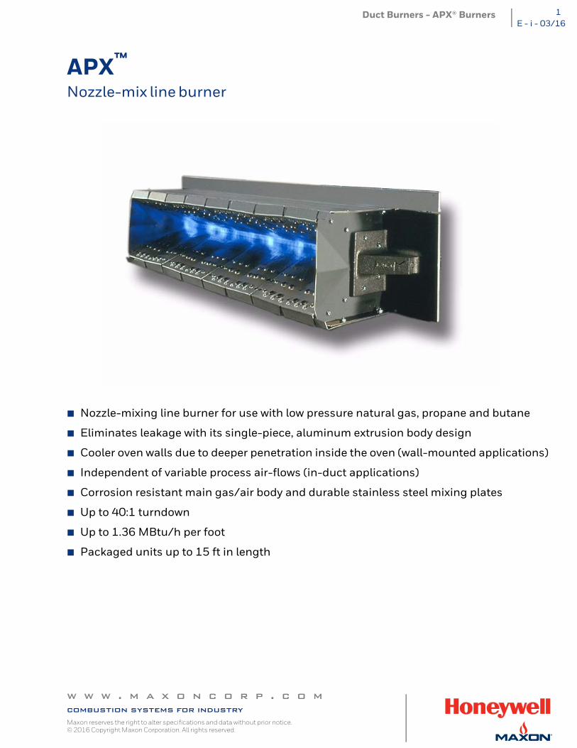
Nozzle-mixing line burner for use with low pressure natural gas, propane and butane
Eliminates leakage with its single-piece, aluminum extrusion body design
Cooler oven walls due to deeper penetration inside the oven (wall-mounted applications)
Independent of variable process air-flows (in-duct applications)
Corrosion resistant main gas/air body and durable stainless steel mixing plates
Up to 40:1 turndown
Up to 1.36 MBtu/h per foot
Packaged units up to 15 ft in length
w w w . m a x o n c o r p . c o mcombustion systems for industryMaxon reserves the right to alter specifications and data without prior notice. © 2016 Copyright Maxon Corporation. All rights reserved.
Duct Burners - APX® Burners2E - i - 03/16
Product description
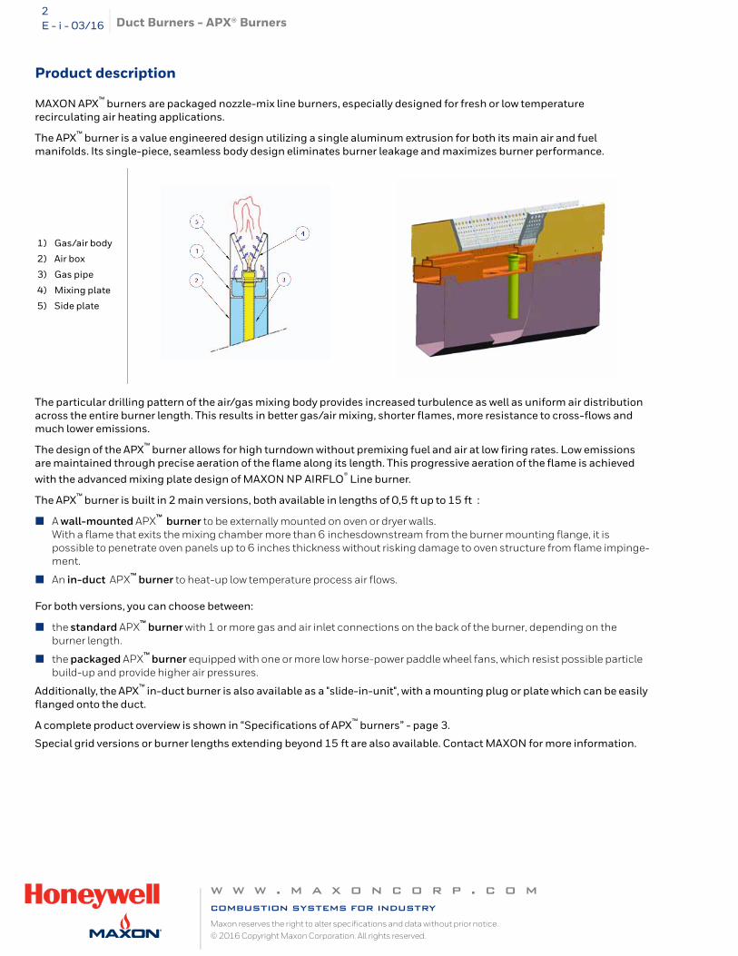
MAXON APX™ burners are packaged nozzle-mix line burners, especially designed for fresh or low temperature recirculating air heating applications.
The APX™ burner is a value engineered design utilizing a single aluminum extrusion for both its main air and fuel manifolds. Its single-piece, seamless body design eliminates burner leakage and maximizes burner performance.
The particular drilling pattern of the air/gas mixing body provides increased turbulence as well as uniform air distribution across the entire burner length. This results in better gas/air mixing, shorter flames, more resistance to cross-flows and much lower emissions.
The design of the APX™ burner allows for high turndown without premixing fuel and air at low firing rates. Low emissions are maintained through precise aeration of the flame along its length. This progressive aeration of the flame is achieved with the advanced mixing plate design of MAXON NP AIRFLO® Line burner.
The APX™ burner is built in 2 main versions, both available in lengths of 0,5 ft up to 15 ft :
A wall-mounted APX™ burner to be externally mounted on oven or dryer walls. With a flame that exits the mixing chamber more than 6 inchesdownstream from the burner mounting flange, it is possible to penetrate oven panels up to 6 inches thickness without risking damage to oven structure from flame impinge-ment.
An in-duct APX™ burner to heat-up low temperature process air flows.
For both versions, you can choose between:
the standard APX™ burner with 1 or more gas and air inlet connections on the back of the burner, depending on the burner length.
the packaged APX™ burner equipped with one or more low horse-power paddle wheel fans, which resist possible particle build-up and provide higher air pressures.
Additionally, the APX™ in-duct burner is also available as a "slide-in-unit", with a mounting plug or plate which can be easily flanged onto the duct.
A complete product overview is shown in “Specifications of APX™ burners” - page 3.
Special grid versions or burner lengths extending beyond 15 ft are also available. Contact MAXON for more information.
1) Gas/air body
2) Air box
3) Gas pipe
4) Mixing plate
5) Side plate
w w w . m a x o n c o r p . c o mcombustion systems for industryMaxon reserves the right to alter specifications and data without prior notice. © 2016 Copyright Maxon Corporation. All rights reserved.
Duct Burners - APX® Burners 3E - i - 03/16
Available APX™ sizes
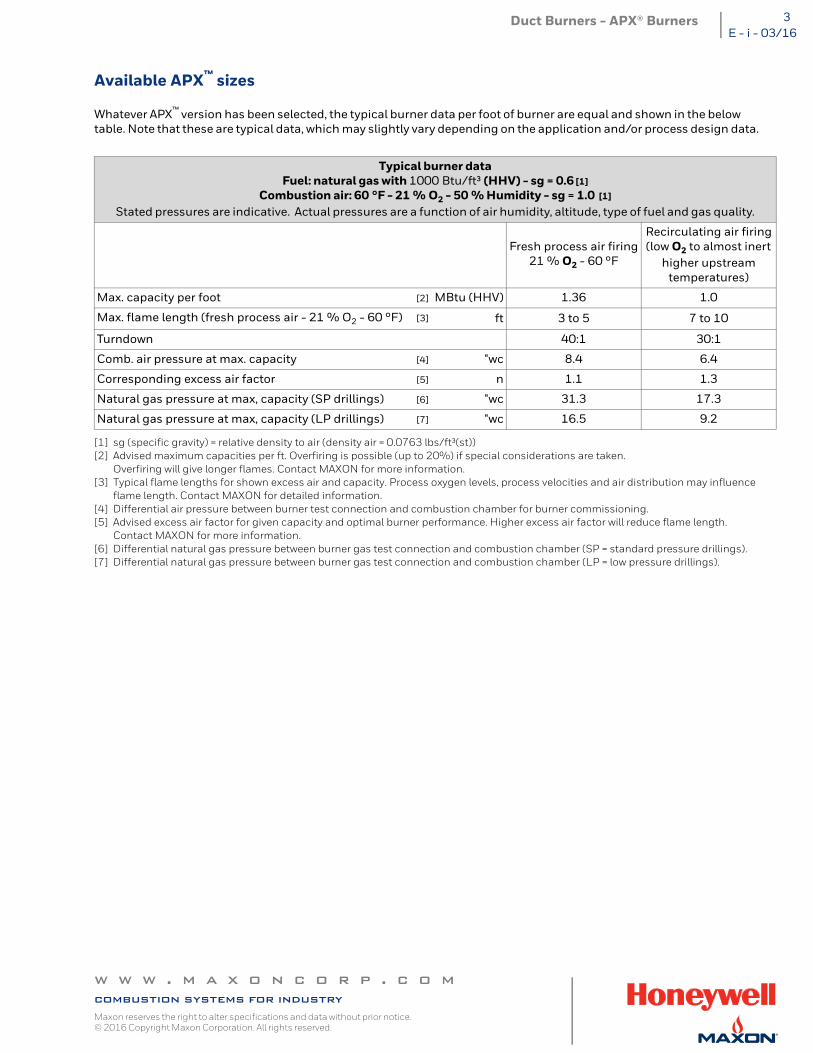
Whatever APX™ version has been selected, the typical burner data per foot of burner are equal and shown in the below table. Note that these are typical data, which may slightly vary depending on the application and/or process design data.
[1] sg (specific gravity) = relative density to air (density air = 0.0763 lbs/ft³(st))[2] Advised maximum capacities per ft. Overfiring is possible (up to 20%) if special considerations are taken.
Overfiring will give longer flames. Contact MAXON for more information.[3] Typical flame lengths for shown excess air and capacity. Process oxygen levels, process velocities and air distribution may influence
flame length. Contact MAXON for detailed information.[4] Differential air pressure between burner test connection and combustion chamber for burner commissioning.[5] Advised excess air factor for given capacity and optimal burner performance. Higher excess air factor will reduce flame length.
Contact MAXON for more information.[6] Differential natural gas pressure between burner gas test connection and combustion chamber (SP = standard pressure drillings).[7] Differential natural gas pressure between burner gas test connection and combustion chamber (LP = low pressure drillings).
Typical burner dataFuel: natural gas with 1000 Btu/ft³ (HHV) - sg = 0.6 [1]
Combustion air: 60 °F - 21 % O2 - 50 % Humidity - sg = 1.0 [1]
Stated pressures are indicative. Actual pressures are a function of air humidity, altitude, type of fuel and gas quality.
Fresh process air firing21 % O2 - 60 °F
Recirculating air firing(low O2 to almost inert
higher upstreamtemperatures)
Max. capacity per foot [2] MBtu (HHV) 1.36 1.0
Max. flame length (fresh process air - 21 % O2 - 60 °F) [3] ft 3 to 5 7 to 10
Turndown 40:1 30:1
Comb. air pressure at max. capacity [4] "wc 8.4 6.4
Corresponding excess air factor [5] n 1.1 1.3
Natural gas pressure at max, capacity (SP drillings) [6] "wc 31.3 17.3
Natural gas pressure at max, capacity (LP drillings) [7] "wc 16.5 9.2
w w w . m a x o n c o r p . c o mcombustion systems for industryMaxon reserves the right to alter specifications and data without prior notice. © 2016 Copyright Maxon Corporation. All rights reserved.
Duct Burners - APX® Burners4E - i - 03/16
Applications
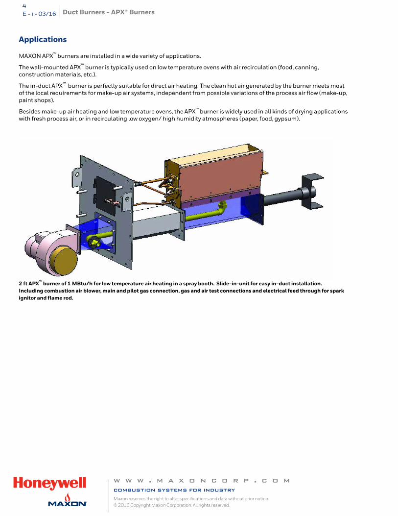
MAXON APX™ burners are installed in a wide variety of applications.
The wall-mounted APX™ burner is typically used on low temperature ovens with air recirculation (food, canning, construction materials, etc.).
The in-duct APX™ burner is perfectly suitable for direct air heating. The clean hot air generated by the burner meets most of the local requirements for make-up air systems, independent from possible variations of the process air flow (make-up, paint shops).
Besides make-up air heating and low temperature ovens, the APX™ burner is widely used in all kinds of drying applications with fresh process air, or in recirculating low oxygen/ high humidity atmospheres (paper, food, gypsum).
2 ft APX™ burner of 1 MBtu/h for low temperature air heating in a spray booth. Slide-in-unit for easy in-duct installation. Including combustion air blower, main and pilot gas connection, gas and air test connections and electrical feed through for spark ignitor and flame rod.
w w w . m a x o n c o r p . c o mcombustion systems for industryMaxon reserves the right to alter specifications and data without prior notice. © 2016 Copyright Maxon Corporation. All rights reserved.
Duct Burners - APX® Burners 5E - i - 03/16
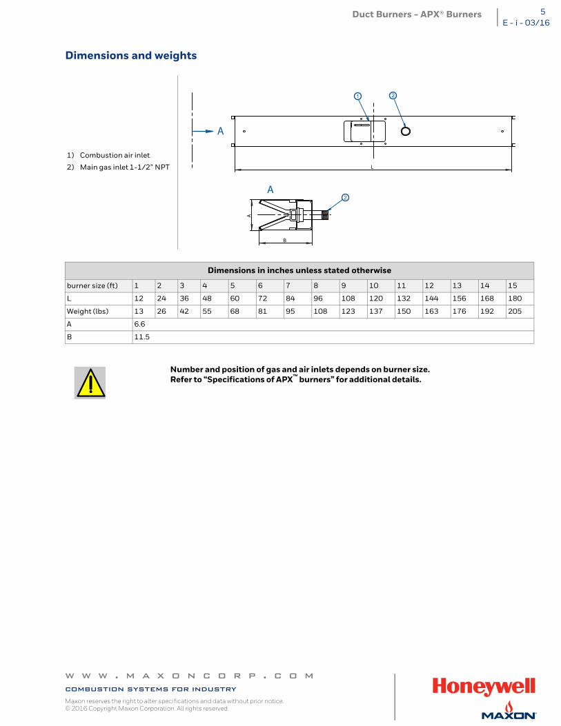
Dimensions and weights
1) Combustion air inlet
2) Main gas inlet 1-1/2” NPT
Dimensions in inches unless stated otherwise
burner size (ft) 1 2 3 4 5 6 7 8 9 10 11 12 13 14 15
L 12 24 36 48 60 72 84 96 108 120 132 144 156 168 180
Weight (lbs) 13 26 42 55 68 81 95 108 123 137 150 163 176 192 205
A 6.6
B 11.5
Number and position of gas and air inlets depends on burner size. Refer to “Specifications of APX™ burners” for additional details.
L
B
A
1 2
2A
A
w w w . m a x o n c o r p . c o mcombustion systems for industryMaxon reserves the right to alter specifications and data without prior notice. © 2016 Copyright Maxon Corporation. All rights reserved.
Duct Burners - APX® Burners6E - i - 03/16
Typical emissions (burners only)
Thanks to the advanced mixing technology of the single-piece gas/air body, MAXON APX™ burners combine excellent flexibility and turndown with very sharp emission levels on both CO and NOx. Contact MAXON for more information.
Read “Specifications of APX™ burners” for correct and complete information on APX™ burners.
w w w . m a x o n c o r p . c o mcombustion systems for industryMaxon reserves the right to alter specifications and data without prior notice. © 2016 Copyright Maxon Corporation. All rights reserved.
Duct Burners - APX® Burners 7E - i - 03/16
Specifications of APX™ burners
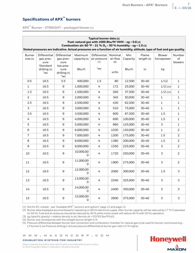
APX™ Burner - STRAIGHT - packaged blower [1]
[1] Not for EC-market - see “Available APX™ versions and options” page 12 and page 13.[2] Burner data displayed assume blower(s) operating on 60 Hz electrical supply. Max. burner capacity will be reduced by 17 % if operated
on 50 Hz. Fuel and air pressure should be reduced by 30 % while motor power will reduce 40 % with 50 Hz operation.[3] sg (specific gravity) = relative density to air (density air = 0.0763 lbs/ft³(st)).[4] Burner size corresponds with the straight burner length in ft.[5] Pressure differential between burner test connection and combustion chamber for natural gas to be used for burner commissioning -
LP burner (Low Pressure drillings). Actual pressure differential at burner gas inlet is 5 % higher.
Typical burner data [2]Fuel: natural gas with 1000 Btu/ft³ HHV - sg = 0.6 [3]
Combustion air: 60 °F - 21 % O2 - 50 % humidity - sg = 1.0 [3]
Stated pressures are indicative. Actual pressures are a function of air humidity, altitude, type of fuel and gas quality.
Burnersize [4]
Differentialgas pres-
sureStandarddrilling [5]
“wc
Differentialgas pres-
surelow pres-
suredrilling [5]
“wc
Maximumcapacity [6]
Btu/h
Differentialair pressure
[7]
“wc
Nominalair flow
[8]
scfm
Min.Capacity
Btu/h
Flame length [9]
in
Blowerhorsepower
hp
Numberof
blowers
0.5 16.5 5.5 400,000 1.5 80 12,500 30-40 1/12 1
1 16.5 9 1,000,000 4 172 25,000 30-40 1/2 [10] 1
1.5 16.5 9 1,500,000 4 260 37,500 30-40 1/2 [10] 1
2 16.5 9 2,000,000 4 345 50,000 30-40 1 1
2.5 16.5 9 2,500,000 4 430 62,500 30-40 1 1
3 16.5 9 3,000,000 4 510 75,000 30-40 1 1
3.5 16.5 9 3,500,000 4 600 87,500 30-40 1.5 1
4 16.5 9 4,000,000 4 690 100,000 30-40 1.5 1
5 16.5 9 5,000,000 4 860 125,000 30-40 3 1
6 16.5 9 6,000,000 4 1030 150,000 30-40 1 2
7 16.5 9 7,000,000 4 1200 175,000 30-40 1.5 2
8 16.5 9 8,000,000 4 1380 200,000 30-40 1.5 2
9 16.5 9 9,000,000 4 1550 225,000 30-40 3 2
10 16.5 9 10,000,000 4 1720 250,000 30-40 3 2
11 16.5 9 11,000,000 4 1900 275,000 30-40 3 2
12 16.5 9 12,000,000 4 2060 300,000 30-40 1.5 3
13 16.5 9 13,000,000 4 2240 325,000 30-40 3 3
14 16.5 9 14,000,000 4 2400 350,000 30-40 3 3
15 16.5 9 15,000,000 4 2600 375,000 30-40 3 3
w w w . m a x o n c o r p . c o mcombustion systems for industryMaxon reserves the right to alter specifications and data without prior notice. © 2016 Copyright Maxon Corporation. All rights reserved.
Duct Burners - APX® Burners8E - i - 03/16
[6] Fresh air firing. When firing in low oxygen environment, max. capacity should be downrated.[7] Differential combustion air pressure between burner air test connection and combustion chamber for commissioning.[8] When firing in balanced combustion chamber.[9] Expected flame length in fresh air firing. Flame length may vary as a function of process air flow distribution, velocity, temperature, oxy-
gen level etc. Contact MAXON for more information.[10]575 volt version in 3/4 HP.
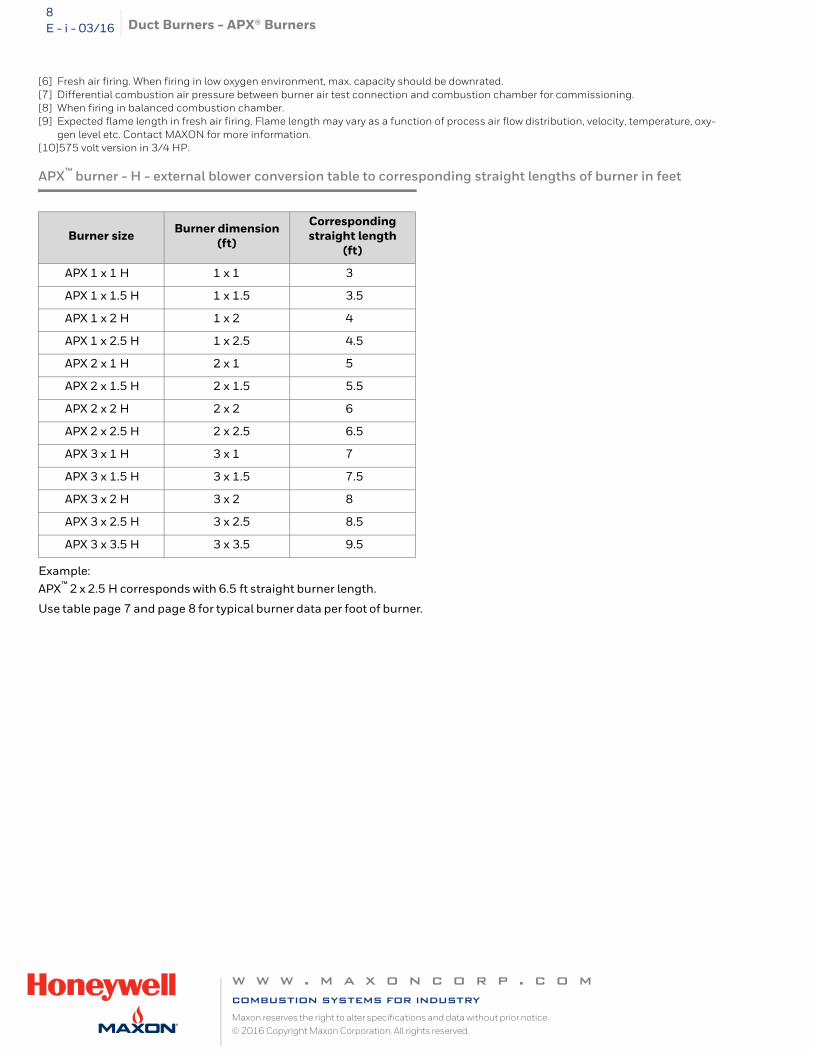
APX™ burner - H - external blower conversion table to corresponding straight lengths of burner in feet
Example:APX™ 2 x 2.5 H corresponds with 6.5 ft straight burner length.
Use table page 7 and page 8 for typical burner data per foot of burner.
Burner size Burner dimension(ft)
Corresponding straight length
(ft)
APX 1 x 1 H 1 x 1 3
APX 1 x 1.5 H 1 x 1.5 3.5
APX 1 x 2 H 1 x 2 4
APX 1 x 2.5 H 1 x 2.5 4.5
APX 2 x 1 H 2 x 1 5
APX 2 x 1.5 H 2 x 1.5 5.5
APX 2 x 2 H 2 x 2 6
APX 2 x 2.5 H 2 x 2.5 6.5
APX 3 x 1 H 3 x 1 7
APX 3 x 1.5 H 3 x 1.5 7.5
APX 3 x 2 H 3 x 2 8
APX 3 x 2.5 H 3 x 2.5 8.5
APX 3 x 3.5 H 3 x 3.5 9.5
w w w . m a x o n c o r p . c o mcombustion systems for industryMaxon reserves the right to alter specifications and data without prior notice. © 2016 Copyright Maxon Corporation. All rights reserved.
Duct Burners - APX® Burners 9E - i - 03/16
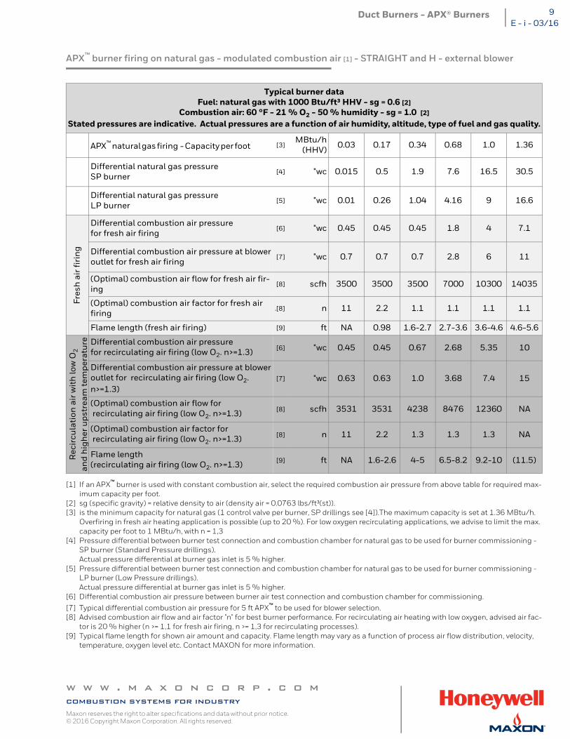
APX™ burner firing on natural gas - modulated combustion air [1] - STRAIGHT and H - external blower
[1] If an APX™ burner is used with constant combustion air, select the required combustion air pressure from above table for required max-imum capacity per foot.
[2] sg (specific gravity) = relative density to air (density air = 0.0763 lbs/ft³(st)).[3] is the minimum capacity for natural gas (1 control valve per burner, SP drillings see [4]).The maximum capacity is set at 1.36 MBtu/h.
Overfiring in fresh air heating application is possible (up to 20 %). For low oxygen recirculating applications, we advise to limit the max. capacity per foot to 1 MBtu/h, with n = 1,3
[4] Pressure differential between burner test connection and combustion chamber for natural gas to be used for burner commissioning - SP burner (Standard Pressure drillings).Actual pressure differential at burner gas inlet is 5 % higher.
[5] Pressure differential between burner test connection and combustion chamber for natural gas to be used for burner commissioning - LP burner (Low Pressure drillings).Actual pressure differential at burner gas inlet is 5 % higher.
[6] Differential combustion air pressure between burner air test connection and combustion chamber for commissioning.
[7] Typical differential combustion air pressure for 5 ft APX™ to be used for blower selection.[8] Advised combustion air flow and air factor "n" for best burner performance. For recirculating air heating with low oxygen, advised air fac-
tor is 20 % higher (n >= 1,1 for fresh air firing, n >= 1,3 for recirculating processes).[9] Typical flame length for shown air amount and capacity. Flame length may vary as a function of process air flow distribution, velocity,
temperature, oxygen level etc. Contact MAXON for more information.
Typical burner dataFuel: natural gas with 1000 Btu/ft³ HHV - sg = 0.6 [2]
Combustion air: 60 °F - 21 % O2 - 50 % humidity - sg = 1.0 [2]
Stated pressures are indicative. Actual pressures are a function of air humidity, altitude, type of fuel and gas quality.
APX™ natural gas firing - Capacity per foot [3]MBtu/h
(HHV) 0.03 0.17 0.34 0.68 1.0 1.36
Differential natural gas pressureSP burner
[4] "wc 0.015 0.5 1.9 7.6 16.5 30.5
Differential natural gas pressure LP burner
[5] "wc 0.01 0.26 1.04 4.16 9 16.6
Fres
h a
ir fi
rin
g
Differential combustion air pressure for fresh air firing
[6] "wc 0.45 0.45 0.45 1.8 4 7.1
Differential combustion air pressure at bloweroutlet for fresh air firing
[7] "wc 0.7 0.7 0.7 2.8 6 11
(Optimal) combustion air flow for fresh air fir-ing
[8] scfh 3500 3500 3500 7000 10300 14035
(Optimal) combustion air factor for fresh air firing
.[8] n 11 2.2 1.1 1.1 1.1 1.1
Flame length (fresh air firing) [9] ft NA 0.98 1.6-2.7 2.7-3.6 3.6-4.6 4.6-5.6
Rec
ircu
lati
on a
ir w
ith
low
O2
and
hig
her
ups
trea
m te
mpe
ratu
re Differential combustion air pressurefor recirculating air firing (low O2. n>=1.3) [6] "wc 0.45 0.45 0.67 2.68 5.35 10
Differential combustion air pressure at bloweroutlet for recirculating air firing (low O2. n>=1.3)
[7] "wc 0.63 0.63 1.0 3.68 7.4 15
(Optimal) combustion air flow for recirculating air firing (low O2. n>=1.3) [8] scfh 3531 3531 4238 8476 12360 NA
(Optimal) combustion air factor for recirculating air firing (low O2. n>=1.3) [8] n 11 2.2 1.3 1.3 1.3 NA
Flame length(recirculating air firing (low O2. n>=1.3) [9] ft NA 1.6-2.6 4-5 6.5-8.2 9.2-10 (11.5)
w w w . m a x o n c o r p . c o mcombustion systems for industryMaxon reserves the right to alter specifications and data without prior notice. © 2016 Copyright Maxon Corporation. All rights reserved.
Duct Burners - APX® Burners10E - i - 03/16
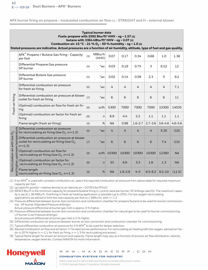
APX burner firing on propane - modulated combustion air flow [1] - STRAIGHT and H - external blower
[1] If an APX™ is used with constant combustion air, select the required combustion air pressure from above table for required maximum capacity per foot.
[2] sg (specific gravity) = relative density to air (density air = 0.0763 lbs/ft³(st))[3] 68303 Btu/h is the minimum capacity for propane/butane firing (1 control valve per burner, SP drillings see [4]). The maximum capac-
ity is set at 1.36 MBtu/h. Overfiring in fresh air heating application is possible (up to 20%). For low oxygen recirculating applications we advise to limit the max.capacity per foot to 1 MBtu/hr, with n = 1.3
[4] Pressure differential between burner test connection and combustion chamber for propane/butane to be used for burner commission-ing - SP burner (Standard Pressure drillings).Actual pressure differential at burner gas inlet is approx. 5 % higher.
[5] Pressure differential between burner test connection and combustion chamber for natural gas to be used for burner commissioning - LP burner (Low Pressure drillings).Actual pressure differential at burner gas inlet is 5 % higher.
[6] Differential combustion air pressure between burner air test connection and combustion chamber for commissioning.
[7] Typical differential combustion air pressure for 5 ft APX™ to be used for blower selection.[8] Advised combustion air flow and air factor "n" for best burner performance. For recirculating air heating with low oxygen, advised air fac-
tor is 20 % higher (n >= 1.1 for fresh air firing, n >= 1.3 for recirculating processes).[9] Typical flame length for shown air amount and capacity. Flame length may vary as a function of process air flow distribution, velocity,
temperature, oxygen level etc. Contact MAXON for more information.
Typical burner dataFuels: propane with 2592 Btu/ft³ HHV - sg = 1.57 [2]
butane with 3364 kBtu/ft³ HHV - sg = 2.07 [2]Combustion air: 15 °C - 21 % O2 - 50 % humidity - sg = 1.0 [2]
Stated pressures are indicative. Actual pressures are a function of air humidity, altitude, type of fuel and gas quality.
APX™ Propane / Butane Gas firing - Capacity per foot
[3]MBtu/h
(HHV) 0.07 0.17 0.34 0.68 1.0 1.36
Differential Propane Gas pressureSP burner
[4] "wc 0.03 0.19 0.75 3 6.52 12
Differential Butane Gas pressure SP burner
[5] "wc 0.02 0.14 0.58 2.3 5 9.2
Fres
h a
ir fi
rin
g
Differential combustion air pressure for fresh air firing
[6] "wc 4 4 4 4 4 7.1
Differential combustion air pressure at bloweroutlet for fresh air firing
[7] "wc 6 6 6 6 6 11
(Optimal) combustion air flow for fresh air fir-ing
[8] scfh 5300 7000 7000 7000 10300 14035
(Optimal) combustion air factor for fresh air firing
.[8] n 8.9 4.4 2.2 1.1 1.1 1.1
Flame length (fresh air firing) [9] ft NA 0.98 1.6-2.7 2.7-3.6 3.6-4.6 4.6-5.6
Rec
ircu
lati
on a
ir w
ith
low
O2
and
hig
her
ups
trea
m te
mpe
ratu
re Differential combustion air pressurefor recirculating air firing (low O2. n>=1.3) [6] "wc 4 4 4 4 5.35 (10)
Differential combustion air pressure at bloweroutlet for recirculating air firing (low O2. n>=1.3)
[7] "wc 6 6 6 6 7.4 (15)
(Optimal) combustion air flow for recirculating air firing (low O2. n>=1.3) [8] scfh 10300 10300 10300 10300 12360 NA
(Optimal) combustion air factor for recirculating air firing (low O2. n>=1.3) [8] n 33 6.6 3.3 1.6 1.3 NA
Flame length(recirculating air firing (low O2. n>=1.3) [9] ft NA 1.6-2.6 4-5 6.5-8.2 9.2-10 (11.5)
w w w . m a x o n c o r p . c o mcombustion systems for industryMaxon reserves the right to alter specifications and data without prior notice. © 2016 Copyright Maxon Corporation. All rights reserved.
Duct Burners - APX® Burners 11E - i - 03/16
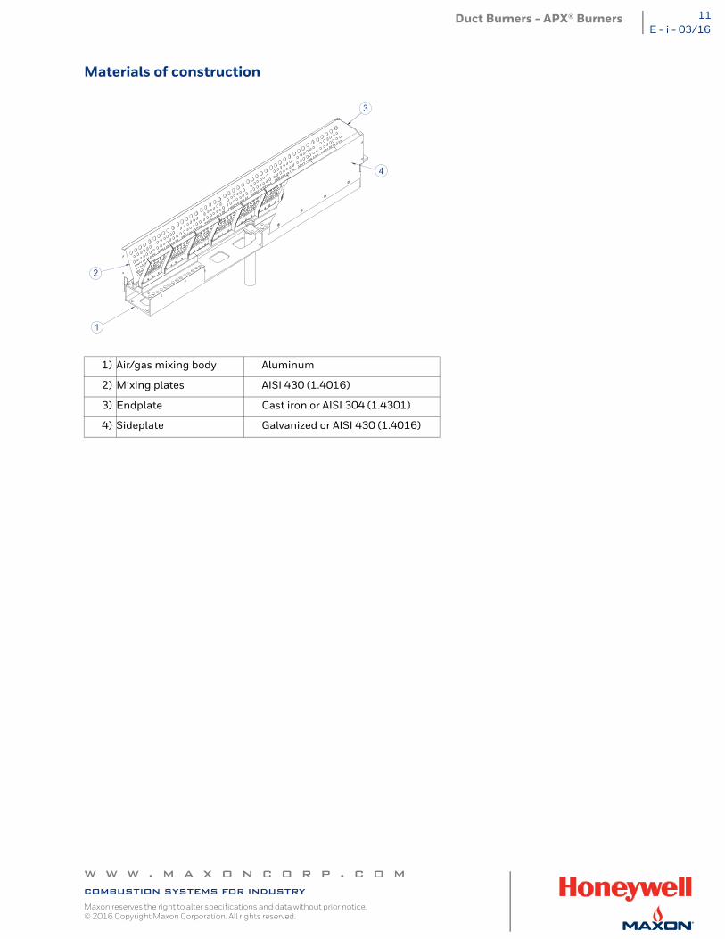
Materials of construction
1) Air/gas mixing body Aluminum
2) Mixing plates AISI 430 (1.4016)
3) Endplate Cast iron or AISI 304 (1.4301)
4) Sideplate Galvanized or AISI 430 (1.4016)
1
2
4
3
w w w . m a x o n c o r p . c o mcombustion systems for industryMaxon reserves the right to alter specifications and data without prior notice. © 2016 Copyright Maxon Corporation. All rights reserved.
Duct Burners - APX® Burners12E - i - 03/16
Selection criteria
Application details
The MAXON APX™ nozzle-mix line burner has been especially designed for low temperature air heating applications, where standard raw gas line burners (MAXON "NP" AIRFLO®) are not suitable.
Thanks to its unique single-piece air/gas mixing body, APX™ strongly differentiate from the regular "box burner", with excellent flame stability and flexibility, also in high modulating and/or low oxygen process air flows.
Basically, APX™ is available in two main versions.
A wall-mounted APX™ to be externally mounted on the oven or dryer wall. Thanks to the flame that exits the mixing chamber more than 0.5 ft downstream from the burner mounting flange, it is possible to penetrate oven panels up to 0.5 ft thickness without risking damage to oven structure from flame impingement.
The in-duct APX™ is installed inside the dryer or make-up air unit to heat-up low temperature process air flows.
Available APX™ versions and options
The two basic APX™ versions, wall-mounted and in-duct, are available in several variations. Below tables give an overview of the different options of each version.
Note that wall-mounted APX™ burners are always mounted on suction side of circulating fans, or in balanced ducts.
Whether slot or continuous flange mounted burner should be selected depends upon the desired amount of cooling/purge air around the burner.
The packaged blower option is not available on the EC-market. For EC-market, same execution can be achieved by selecting the external blower option, and mounting an appropriate European blower direct onto the air inlet connection of the burner.
To comply with local codes and directives, special provisions may be required to correctly safeguard the minimum combustion air pressure in case multiple blowers are mounted on the burner.
w w w . m a x o n c o r p . c o mcombustion systems for industryMaxon reserves the right to alter specifications and data without prior notice. © 2016 Copyright Maxon Corporation. All rights reserved.
Duct Burners - APX® Burners 13E - i - 03/16
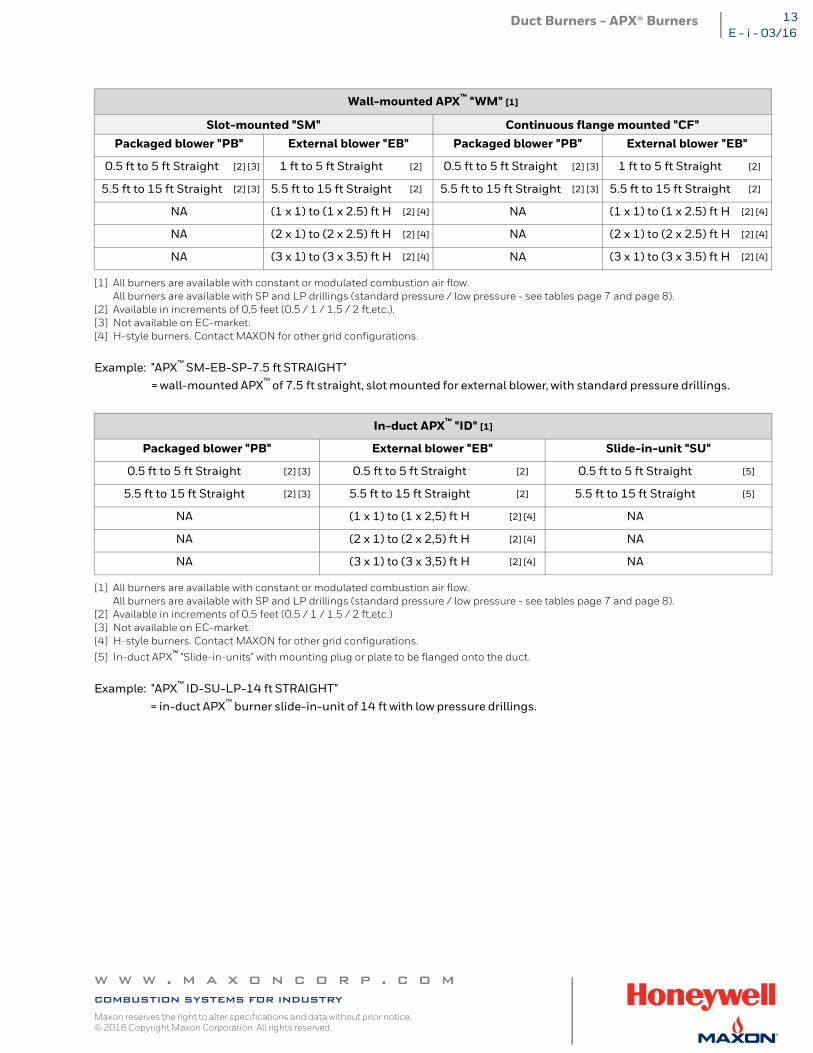
[1] All burners are available with constant or modulated combustion air flow.All burners are available with SP and LP drillings (standard pressure / low pressure - see tables page 7 and page 8).
[2] Available in increments of 0,5 feet (0.5 / 1 / 1.5 / 2 ft,etc.).[3] Not available on EC-market. [4] H-style burners. Contact MAXON for other grid configurations.
Example: "APX™ SM-EB-SP-7.5 ft STRAIGHT"= wall-mounted APX™ of 7.5 ft straight, slot mounted for external blower, with standard pressure drillings.
[1] All burners are available with constant or modulated combustion air flow.All burners are available with SP and LP drillings (standard pressure / low pressure - see tables page 7 and page 8).
[2] Available in increments of 0.5 feet (0.5 / 1 / 1.5 / 2 ft,etc.)[3] Not available on EC-market.[4] H-style burners. Contact MAXON for other grid configurations.
[5] In-duct APX™ "Slide-in-units" with mounting plug or plate to be flanged onto the duct.
Example: "APX™ ID-SU-LP-14 ft STRAIGHT"= in-duct APX™ burner slide-in-unit of 14 ft with low pressure drillings.
Wall-mounted APX™ "WM" [1]
Slot-mounted "SM" Continuous flange mounted "CF"Packaged blower "PB" External blower "EB" Packaged blower "PB" External blower "EB"
0.5 ft to 5 ft Straight [2] [3] 1 ft to 5 ft Straight [2] 0.5 ft to 5 ft Straight [2] [3] 1 ft to 5 ft Straight [2]
5.5 ft to 15 ft Straight [2] [3] 5.5 ft to 15 ft Straight [2] 5.5 ft to 15 ft Straight [2] [3] 5.5 ft to 15 ft Straight [2]
NA (1 x 1) to (1 x 2.5) ft H [2] [4] NA (1 x 1) to (1 x 2.5) ft H [2] [4]
NA (2 x 1) to (2 x 2.5) ft H [2] [4] NA (2 x 1) to (2 x 2.5) ft H [2] [4]
NA (3 x 1) to (3 x 3.5) ft H [2] [4] NA (3 x 1) to (3 x 3.5) ft H [2] [4]
In-duct APX™ "ID" [1]
Packaged blower "PB" External blower "EB" Slide-in-unit "SU"
0.5 ft to 5 ft Straight [2] [3] 0.5 ft to 5 ft Straight [2] 0.5 ft to 5 ft Straight [5]
5.5 ft to 15 ft Straight [2] [3] 5.5 ft to 15 ft Straight [2] 5.5 ft to 15 ft Straight [5]
NA (1 x 1) to (1 x 2,5) ft H [2] [4] NA
NA (2 x 1) to (2 x 2,5) ft H [2] [4] NA
NA (3 x 1) to (3 x 3,5) ft H [2] [4] NA
w w w . m a x o n c o r p . c o mcombustion systems for industryMaxon reserves the right to alter specifications and data without prior notice. © 2016 Copyright Maxon Corporation. All rights reserved.
Duct Burners - APX® Burners14E - i - 03/16
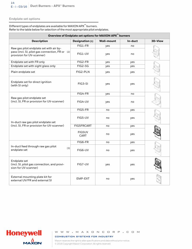
Endplate set options
Different types of endplates are available for MAXON APX™ burners. Refer to the table below for selection of the most appropriate pilot endplates.
Overview of Endplate set options for MAXON APX™ burners
Description Designation [1] Wall-mount In-duct 3D-View
Raw gas pilot endplate set with air by-pass (incl. SI, pilot gas connection, FR or provision for UV-scanner)
[2]
FIG1-FR yes no
FIG1-UV yes no
Endplate set with FR only FIG2-FR yes yesEndplate set with sight glass only FIG2-SG yes yes
Plain endplate set FIG2-PLN yes yes
Endplate set for direct ignition(with SI only) FIG3-SI yes yes
Raw gas pilot endplate set (incl. SI, FR or provision for UV-scanner)
FIG4-FR yes no
FIG4-UV yes no
In-duct raw gas pilot endplate set(incl. SI, FR or provision for UV-scanner)
FIG5-FR no yes
FIG5-UV no yes
FIG5FRCART no yes
FIG5UVCART no yes
In-duct feed through raw gas pilot endplate set
[3]
FIG6-FR no yes
FIG6-UV no yes
Endplate set(incl. SI, pilot gas connection, and provi-sion for UV scanner)
FIG7-UV yes yes
External mounting plate kit for external UV/FR and external SI EMP-EXT no yes
w w w . m a x o n c o r p . c o mcombustion systems for industryMaxon reserves the right to alter specifications and data without prior notice. © 2016 Copyright Maxon Corporation. All rights reserved.
Duct Burners - APX® Burners 15E - i - 03/16
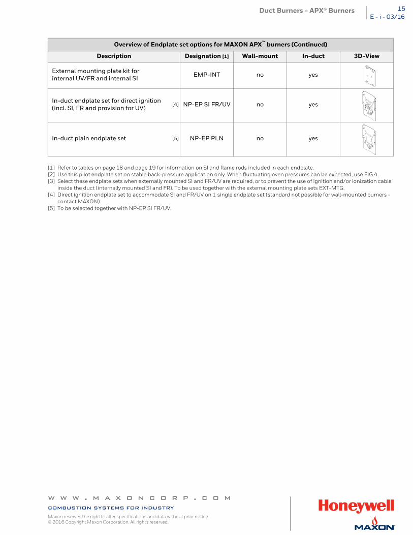
[1] Refer to tables on page 18 and page 19 for information on SI and flame rods included in each endplate.[2] Use this pilot endplate set on stable back-pressure application only. When fluctuating oven pressures can be expected, use FIG.4.[3] Select these endplate sets when externally mounted SI and FR/UV are required, or to prevent the use of ignition and/or ionization cable
inside the duct (internally mounted SI and FR). To be used together with the external mounting plate sets EXT-MTG.[4] Direct ignition endplate set to accommodate SI and FR/UV on 1 single endplate set (standard not possible for wall-mounted burners -
contact MAXON).[5] To be selected together with NP-EP SI FR/UV.
External mounting plate kit for internal UV/FR and internal SI EMP-INT no yes
In-duct endplate set for direct ignition(incl. SI, FR and provision for UV)
[4] NP-EP SI FR/UV no yes
In-duct plain endplate set [5] NP-EP PLN no yes
Overview of Endplate set options for MAXON APX™ burners (Continued)
Description Designation [1] Wall-mount In-duct 3D-View
w w w . m a x o n c o r p . c o mcombustion systems for industryMaxon reserves the right to alter specifications and data without prior notice. © 2016 Copyright Maxon Corporation. All rights reserved.
Duct Burners - APX® Burners16E - i - 03/16
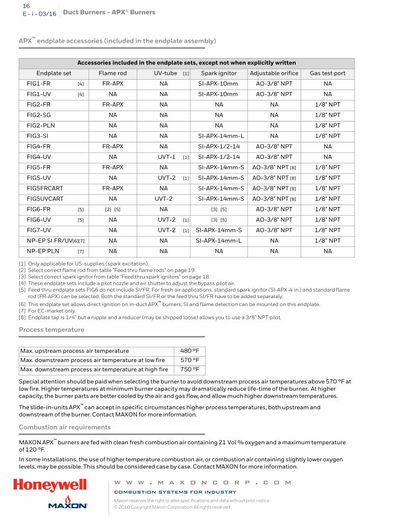
APX™ endplate accessories (included in the endplate assembly)
[1] Only applicable for US-supplies (spark excitation).[2] Select correct flame rod from table "Feed thru flame rods" on page 19.[3] Select correct spark ignitor from table "Feed thru spark ignitors" on page 18.[4] These endplate sets include a pilot nozzle and air shutter to adjust the bypass pilot air.[5] Feed thru endplate sets FIG6 do not include SI/FR. For fresh air applications, standard spark ignitor (SI-APX-4 in.) and standard flame
rod (FR-APX) can be selected. Both the standard SI/FR or the feed thru SI/FR have to be added separately.
[6] This endplate set allows direct ignition on in-duct APX™ burners; SI and flame detection can be mounted on this endplate.[7] For EC-market only.[8] Endplate tap is 1/4” but a nipple and a reducer (may be shipped loose) allows you to use a 3/8” NPT pilot.
Process temperature
Special attention should be paid when selecting the burner to avoid downstream process air temperatures above 570 °F at low fire. Higher temperatures at minimum burner capacity may dramatically reduce life-time of the burner. At higher capacity, the burner parts are better cooled by the air and gas flow, and allow much higher downstream temperatures.
The slide-in-units APX™ can accept in specific circumstances higher process temperatures, both upstream and downstream of the burner. Contact MAXON for more information.
Combustion air requirements
MAXON APX™ burners are fed with clean fresh combustion air containing 21 Vol % oxygen and a maximum temperature of 120 °F.
In some installations, the use of higher temperature combustion air, or combustion air containing slightly lower oxygen levels, may be possible. This should be considered case by case. Contact MAXON for more information.
Accessories included in the endplate sets, except not when explicitly written
Endplate set Flame rod UV-tube [1] Spark ignitor Adjustable orifice Gas test port
FIG1-FR [4] FR-APX NA SI-APX-10mm AO-3/8" NPT NA
FIG1-UV [4] NA NA SI-APX-10mm AO-3/8" NPT NA
FIG2-FR FR-APX NA NA NA 1/8" NPT
FIG2-SG NA NA NA NA 1/8" NPT
FIG2-PLN NA NA NA NA 1/8" NPT
FIG3-SI NA NA SI-APX-14mm-L NA 1/8" NPT
FIG4-FR FR-APX NA SI-APX-1/2-14 AO-3/8" NPT NA
FIG4-UV NA UVT-1 [1] SI-APX-1/2-14 AO-3/8" NPT NA
FIG5-FR FR-APX NA SI-APX-14mm-S AO-3/8" NPT [8] 1/8" NPT
FIG5-UV NA UVT-2 [1] SI-APX-14mm-S AO-3/8" NPT [8] 1/8" NPT
FIG5FRCART FR-APX NA SI-APX-14mm-S AO-3/8" NPT [8] 1/8" NPT
FIG5UVCART NA UVT-2 SI-APX-14mm-S AO-3/8" NPT [8] 1/8" NPT
FIG6-FR [5] [2] [5] NA [3] [5] AO-3/8" NPT 1/8" NPT
FIG6-UV [5] NA UVT-2 [1] [3] [5] AO-3/8" NPT 1/8" NPT
FIG7-UV NA UVT-2 [1] SI-APX-14mm-S AO-3/8" NPT 1/8” NPT
NP-EP SI FR/UV[6][7] NA NA SI-APX-14mm-L NA 1/8” NPT
NP-EP PLN [7] NA NA NA NA NA
Max. upstream process air temperature 480 °F
Max. downstream process air temperature at low fire 570 °F
Max. downstream process air temperature at high fire 750 °F
w w w . m a x o n c o r p . c o mcombustion systems for industryMaxon reserves the right to alter specifications and data without prior notice. © 2016 Copyright Maxon Corporation. All rights reserved.
Duct Burners - APX® Burners 17E - i - 03/16
Modulated or constant combustion air
All MAXON APX™ burners can operate with constant or fixed air flow, as well as with modulated air flow.
At constant air flow, the required differential combustion air pressure (refer to table on page 9, page 10 and page 11) is set by a fixed air damper (burner air inlet or fan) and the combustion air flow through the burner is constant for all burner firing rates (always maximum air flow).
At modulating air flow, an additional air control valve is adjusting the combustion air in function of burner capacity.
The choice of whether constant or modulated air flow should be selected highly depends on the application and the desired emissions on CO and NOx. Refer to “Expected Emissions" on page 20 for more details.
Ratio control
In case the burner is operated with modulated air flow, best performance is realized when the burner is adjusted with ratios as indicated in the table on page 9 and page 10. This can be achieved with MAXON MICRO-RATIO® valves or SMARTLINK® MRV.
Changes of combustion air temperature, system back pressure variations, and other parameters could influence gas/air ratio if the control system is not designed for compensation. Contact MAXON for more information.
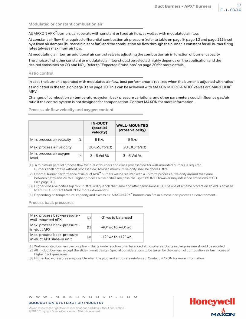
Process air flow velocity and oxygen content
[1] A minimum parallel process flow for in-duct burners and cross process flow for wall-mounted burners is required. Burners shall not fire without process flow. Advised minimum velocity shall be above 6 ft/s.
[2] Optimal burner performance of in-duct APX™ burners will be realized with a uniform process air velocity around the flame between 6 ft/s and 26 ft/s. Higher process air velocities are possible (up to 65 ft/s), however may influence emissions of CO (see page 20).
[3] Higher cross-velocities (up to 29.5 ft/s) will quench the flame and affect emissions (CO).The use of a flame protection shield is advised to limit CO. Contact MAXON for more information.
[4] Depending on temperature, capacity and excess air, MAXON APX™ burners can fire in almost inert process air environment.
Process back pressures
[1] Wall-mounted burners can only fire in ducts under suction or in balanced atmospheres. Ducts in overpressure should be avoided.[2] All in-duct burners, except the slide-in-unit design. Special considerations to be taken for the design of combustion air fan in case of
higher back-pressures.[3] Higher back-pressures are possible when the plug and airbox are reinforced. Contact MAXON for more information.
IN-DUCT(parallel velocity)
WALL-MOUNTED(cross velocity)
Min. process air velocity [1] 6 ft/s 6 ft/s
Max. process air velocity 26 (65) ft/s[2] 20 (30) ft/s[3]
Min. process air oxygen level
[4] 3 - 6 Vol % 3 - 6 Vol %
Max. process back-pressure - wall-mounted APX
[1] -2" wc to balanced
Max. process back-pressure - in-duct APX
[2] -40" wc to +40" wc
Max. process back-pressure - in-duct APX slide-in unit
[3] -12" wc to +12" wc
w w w . m a x o n c o r p . c o mcombustion systems for industryMaxon reserves the right to alter specifications and data without prior notice. © 2016 Copyright Maxon Corporation. All rights reserved.
Duct Burners - APX® Burners18E - i - 03/16
Piloting & ignition
APX™ burners, equipped with one of the raw gas pilot endplate sets (see table on page 14), will generate a stable pilot flame, used to ignite the burner on main flame. After the main burner is ignited, the pilot shall be interrupted. Permanent pilot is not advised. Use the main burner at minimum capacity for continuous operation.
Direct ignition of APX™ burners is also possible, if accepted by local codes. Note that only in-duct APX™ burners offer direct ignition endplates which accommodate spark ignitor and flame detection in the same endplate set. Direct ignition wall-mounted burners need 1 endplate set for the SI and another endplate set to mount the flame detector.
For both pilot and direct ignition, use ignition transformers min. 5000 V - 20 mA.
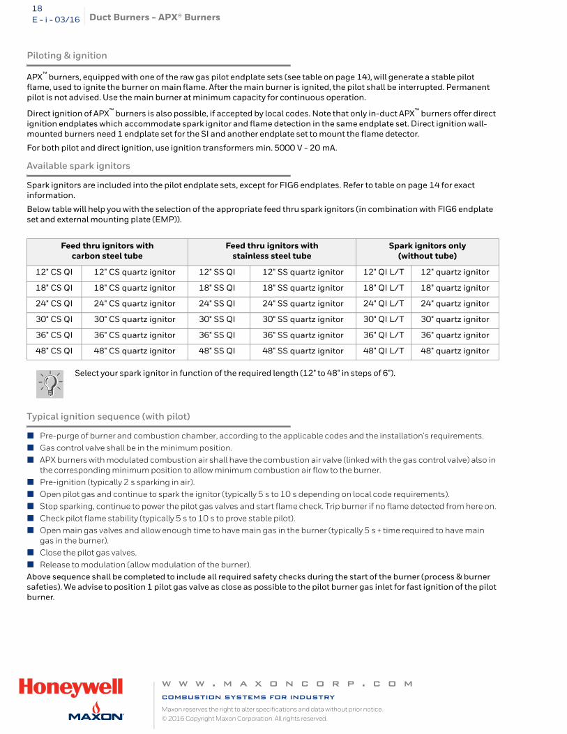
Available spark ignitors
Spark ignitors are included into the pilot endplate sets, except for FIG6 endplates. Refer to table on page 14 for exact information.
Below table will help you with the selection of the appropriate feed thru spark ignitors (in combination with FIG6 endplate set and external mounting plate (EMP)).
Typical ignition sequence (with pilot)
Pre-purge of burner and combustion chamber, according to the applicable codes and the installation's requirements. Gas control valve shall be in the minimum position. APX burners with modulated combustion air shall have the combustion air valve (linked with the gas control valve) also in
the corresponding minimum position to allow minimum combustion air flow to the burner. Pre-ignition (typically 2 s sparking in air). Open pilot gas and continue to spark the ignitor (typically 5 s to 10 s depending on local code requirements). Stop sparking, continue to power the pilot gas valves and start flame check. Trip burner if no flame detected from here on. Check pilot flame stability (typically 5 s to 10 s to prove stable pilot). Open main gas valves and allow enough time to have main gas in the burner (typically 5 s + time required to have main
gas in the burner). Close the pilot gas valves. Release to modulation (allow modulation of the burner).Above sequence shall be completed to include all required safety checks during the start of the burner (process & burner safeties). We advise to position 1 pilot gas valve as close as possible to the pilot burner gas inlet for fast ignition of the pilot burner.
Feed thru ignitors with carbon steel tube
Feed thru ignitors with stainless steel tube
Spark ignitors only(without tube)
12" CS QI 12" CS quartz ignitor 12" SS QI 12" SS quartz ignitor 12" QI L/T 12" quartz ignitor
18" CS QI 18" CS quartz ignitor 18" SS QI 18" SS quartz ignitor 18" QI L/T 18" quartz ignitor
24" CS QI 24" CS quartz ignitor 24" SS QI 24" SS quartz ignitor 24" QI L/T 24" quartz ignitor
30" CS QI 30" CS quartz ignitor 30" SS QI 30" SS quartz ignitor 30" QI L/T 30" quartz ignitor
36" CS QI 36" CS quartz ignitor 36" SS QI 36" SS quartz ignitor 36" QI L/T 36" quartz ignitor
48" CS QI 48" CS quartz ignitor 48" SS QI 48" SS quartz ignitor 48" QI L/T 48" quartz ignitor
Select your spark ignitor in function of the required length (12" to 48" in steps of 6").
w w w . m a x o n c o r p . c o mcombustion systems for industryMaxon reserves the right to alter specifications and data without prior notice. © 2016 Copyright Maxon Corporation. All rights reserved.
Duct Burners - APX® Burners 19E - i - 03/16
Flame supervision
The flame of APX™ burners can be supervised with a flame rod or UV-scanner.
Depending on the application, different versions of endplate sets accommodating different types of flame rods can be selected. Refer to table page 14 (Overview of endplate set options) and table page 16 (APX™ accessories) for more information.
For poor quality propane, LPG or butane, we advise to use UV-scanners only.
Only use the appropriate positions on the MAXON endplate sets for correct and safe flame supervision. Every other position is not acceptable and may cause unsafe situations.
Refer to the user manual of the UV-scanner for correct installation and operating instructions.
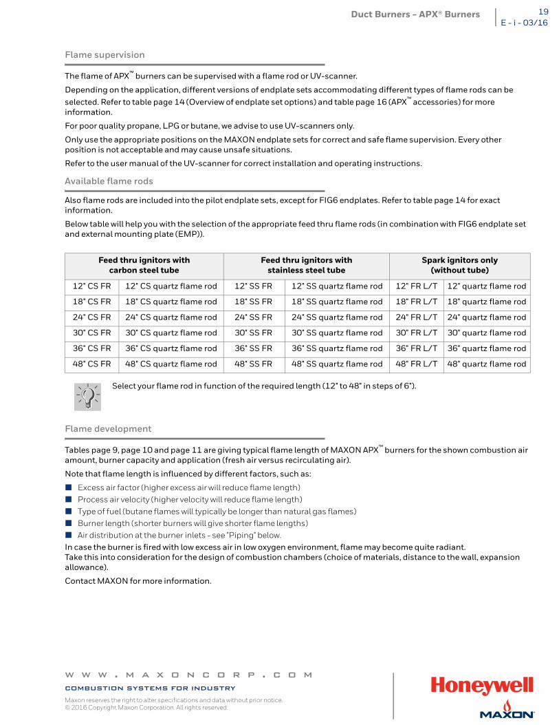
Available flame rods
Also flame rods are included into the pilot endplate sets, except for FIG6 endplates. Refer to table page 14 for exact information.
Below table will help you with the selection of the appropriate feed thru flame rods (in combination with FIG6 endplate set and external mounting plate (EMP)).
Flame development
Tables page 9, page 10 and page 11 are giving typical flame length of MAXON APX™ burners for the shown combustion air amount, burner capacity and application (fresh air versus recirculating air).
Note that flame length is influenced by different factors, such as:
Excess air factor (higher excess air will reduce flame length) Process air velocity (higher velocity will reduce flame length) Type of fuel (butane flames will typically be longer than natural gas flames) Burner length (shorter burners will give shorter flame lengths) Air distribution at the burner inlets - see "Piping" below.In case the burner is fired with low excess air in low oxygen environment, flame may become quite radiant. Take this into consideration for the design of combustion chambers (choice of materials, distance to the wall, expansion allowance).
Contact MAXON for more information.
Feed thru ignitors with carbon steel tube
Feed thru ignitors with stainless steel tube
Spark ignitors only(without tube)
12" CS FR 12" CS quartz flame rod 12" SS FR 12" SS quartz flame rod 12" FR L/T 12" quartz flame rod
18" CS FR 18" CS quartz flame rod 18" SS FR 18" SS quartz flame rod 18" FR L/T 18" quartz flame rod
24" CS FR 24" CS quartz flame rod 24" SS FR 24" SS quartz flame rod 24" FR L/T 24" quartz flame rod
30" CS FR 30" CS quartz flame rod 30" SS FR 30" SS quartz flame rod 30" FR L/T 30" quartz flame rod
36" CS FR 36" CS quartz flame rod 36" SS FR 36" SS quartz flame rod 36" FR L/T 36" quartz flame rod
48" CS FR 48" CS quartz flame rod 48" SS FR 48" SS quartz flame rod 48" FR L/T 48" quartz flame rod
Select your flame rod in function of the required length (12" to 48" in steps of 6").
w w w . m a x o n c o r p . c o mcombustion systems for industryMaxon reserves the right to alter specifications and data without prior notice. © 2016 Copyright Maxon Corporation. All rights reserved.
Duct Burners - APX® Burners20E - i - 03/16
Piping
Except for the slide-in-units where the air and gas distribution is incorporated into the burner design, special attention should be paid to the execution of air and gas manifolds feeding the air and gas inlet(s) of all the other APX™ burner versions.
Common engineering practice should be followed to equally feed the burner at each air and gas connection. Prevent too high velocities which may cause unequal pressure build-up. Burner and piping shall be independently supported to allow for thermal expansion, to prevent any stress on the burner inlets and to prevent the transmission of vibrations.
Fuels
MAXON APX™ burners can fire natural gas, propane, butane and LPG and are able to fire multiple fuels simultaneously, if the control system is properly designed.
Alternative fuels may be possible. Contact MAXON for more information.
Expected Emissions
The clean hot air generated by MAXON APX™ burners meets most of the local requirements of make-up air systems, over the full turndown of the burners.
Also in low temperature ovens and drying systems, MAXON APX™ burners are able to fire with both low NOx and CO, over its entire turndown, meeting the most stringent local emission requirements.
The production of pollutants can be highly dependant upon burner application and installation. Differing temperatures, process velocities, oxygen levels, fuels and other process related factors such as unequal process air distribution can all influence the actual level of emissions produced. No guarantee of emissions is intended or implied on the above.
Contact MAXON for evaluation of expected emissions on your typical application.
w w w . m a x o n c o r p . c o mcombustion systems for industryMaxon reserves the right to alter specifications and data without prior notice. © 2016 Copyright Maxon Corporation. All rights reserved.
Duct Burners - APX® Burners 21E - i - 03/16
Dimensions and weights
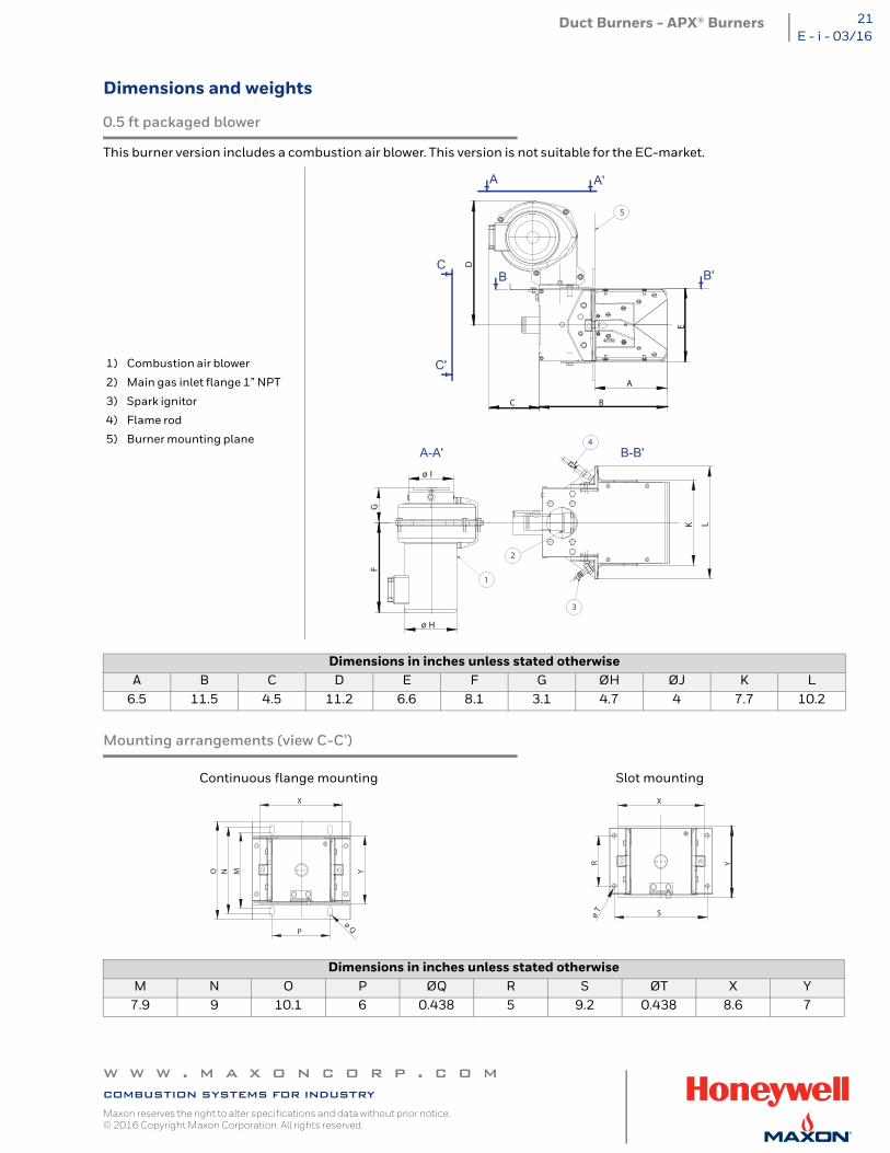
0.5 ft packaged blower
This burner version includes a combustion air blower. This version is not suitable for the EC-market.
Mounting arrangements (view C-C’)
1) Combustion air blower
2) Main gas inlet flange 1” NPT
3) Spark ignitor
4) Flame rod
5) Burner mounting plane
Dimensions in inches unless stated otherwiseA B C D E F G ØH ØJ K L
6.5 11.5 4.5 11.2 6.6 8.1 3.1 4.7 4 7.7 10.2
Continuous flange mounting Slot mounting
Dimensions in inches unless stated otherwiseM N O P ØQ R S ØT X Y
7.9 9 10.1 6 0.438 5 9.2 0.438 8.6 7
A A'
B B'
2
1
B-B'A-A'4
5
3
D
A
BC
ø H
FG
ø I
EK L
C
C'
X
YMNO
Pø
Q
X
YR
SøT
w w w . m a x o n c o r p . c o mcombustion systems for industryMaxon reserves the right to alter specifications and data without prior notice. © 2016 Copyright Maxon Corporation. All rights reserved.
Duct Burners - APX® Burners22E - i - 03/16
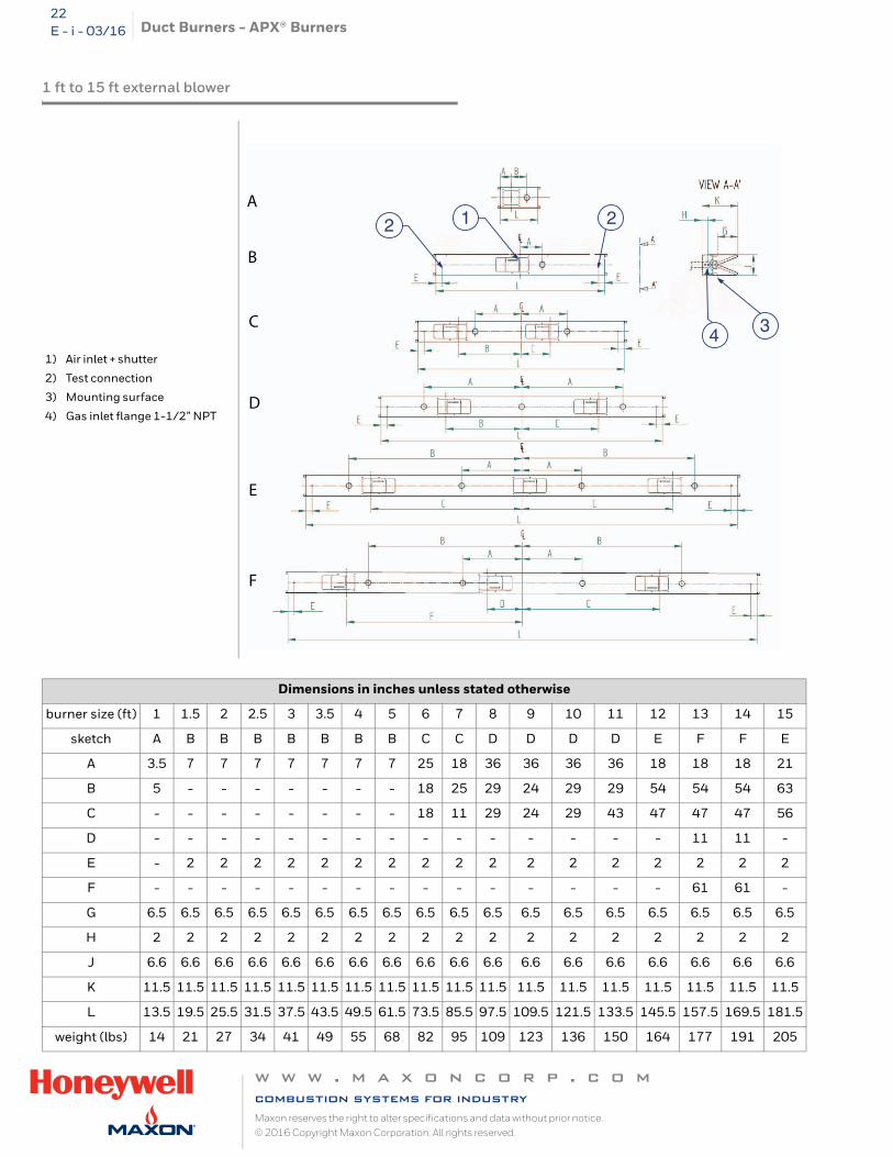
1 ft to 15 ft external blower
1) Air inlet + shutter
2) Test connection
3) Mounting surface
4) Gas inlet flange 1-1/2” NPT
Dimensions in inches unless stated otherwise
burner size (ft) 1 1.5 2 2.5 3 3.5 4 5 6 7 8 9 10 11 12 13 14 15
sketch A B B B B B B B C C D D D D E F F E
A 3.5 7 7 7 7 7 7 7 25 18 36 36 36 36 18 18 18 21
B 5 - - - - - - - 18 25 29 24 29 29 54 54 54 63
C - - - - - - - - 18 11 29 24 29 43 47 47 47 56
D - - - - - - - - - - - - - - - 11 11 -
E - 2 2 2 2 2 2 2 2 2 2 2 2 2 2 2 2 2
F - - - - - - - - - - - - - - - 61 61 -
G 6.5 6.5 6.5 6.5 6.5 6.5 6.5 6.5 6.5 6.5 6.5 6.5 6.5 6.5 6.5 6.5 6.5 6.5
H 2 2 2 2 2 2 2 2 2 2 2 2 2 2 2 2 2 2
J 6.6 6.6 6.6 6.6 6.6 6.6 6.6 6.6 6.6 6.6 6.6 6.6 6.6 6.6 6.6 6.6 6.6 6.6
K 11.5 11.5 11.5 11.5 11.5 11.5 11.5 11.5 11.5 11.5 11.5 11.5 11.5 11.5 11.5 11.5 11.5 11.5
L 13.5 19.5 25.5 31.5 37.5 43.5 49.5 61.5 73.5 85.5 97.5 109.5 121.5 133.5 145.5 157.5 169.5 181.5
weight (lbs) 14 21 27 34 41 49 55 68 82 95 109 123 136 150 164 177 191 205
12 2
4 3
A
B
C
D
E
F
w w w . m a x o n c o r p . c o mcombustion systems for industryMaxon reserves the right to alter specifications and data without prior notice. © 2016 Copyright Maxon Corporation. All rights reserved.
Duct Burners - APX® Burners 23E - i - 03/16
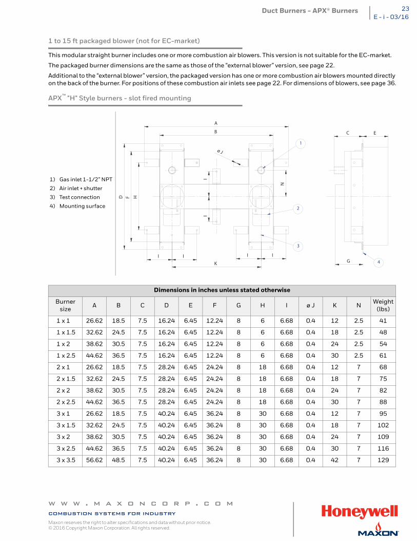
1 to 15 ft packaged blower (not for EC-market)
This modular straight burner includes one or more combustion air blowers. This version is not suitable for the EC-market.
The packaged burner dimensions are the same as those of the “external blower” version, see page 22.
Additional to the “external blower” version, the packaged version has one or more combustion air blowers mounted directly on the back of the burner. For positions of these combustion air inlets see page 22. For dimensions of blowers, see page 36.
APX™ "H" Style burners - slot fired mounting
1) Gas inlet 1-1/2” NPT
2) Air inlet + shutter
3) Test connection
4) Mounting surface
Dimensions in inches unless stated otherwise
Burner size A B C D E F G H I ø J K N Weight
(lbs)
1 x 1 26.62 18.5 7.5 16.24 6.45 12.24 8 6 6.68 0.4 12 2.5 41
1 x 1.5 32.62 24.5 7.5 16.24 6.45 12.24 8 6 6.68 0.4 18 2.5 48
1 x 2 38.62 30.5 7.5 16.24 6.45 12.24 8 6 6.68 0.4 24 2.5 54
1 x 2.5 44.62 36.5 7.5 16.24 6.45 12.24 8 6 6.68 0.4 30 2.5 61
2 x 1 26.62 18.5 7.5 28.24 6.45 24.24 8 18 6.68 0.4 12 7 68
2 x 1.5 32.62 24.5 7.5 28.24 6.45 24.24 8 18 6.68 0.4 18 7 75
2 x 2 38.62 30.5 7.5 28.24 6.45 24.24 8 18 6.68 0.4 24 7 82
2 x 2.5 44.62 36.5 7.5 28.24 6.45 24.24 8 18 6.68 0.4 30 7 88
3 x 1 26.62 18.5 7.5 40.24 6.45 36.24 8 30 6.68 0.4 12 7 95
3 x 1.5 32.62 24.5 7.5 40.24 6.45 36.24 8 30 6.68 0.4 18 7 102
3 x 2 38.62 30.5 7.5 40.24 6.45 36.24 8 30 6.68 0.4 24 7 109
3 x 2.5 44.62 36.5 7.5 40.24 6.45 36.24 8 30 6.68 0.4 30 7 116
3 x 3.5 56.62 48.5 7.5 40.24 6.45 36.24 8 30 6.68 0.4 42 7 129
A
BHFD
I I I I
I
K
I
N
ø J
G
C E
2
3
1
4
w w w . m a x o n c o r p . c o mcombustion systems for industryMaxon reserves the right to alter specifications and data without prior notice. © 2016 Copyright Maxon Corporation. All rights reserved.
Duct Burners - APX® Burners24E - i - 03/16
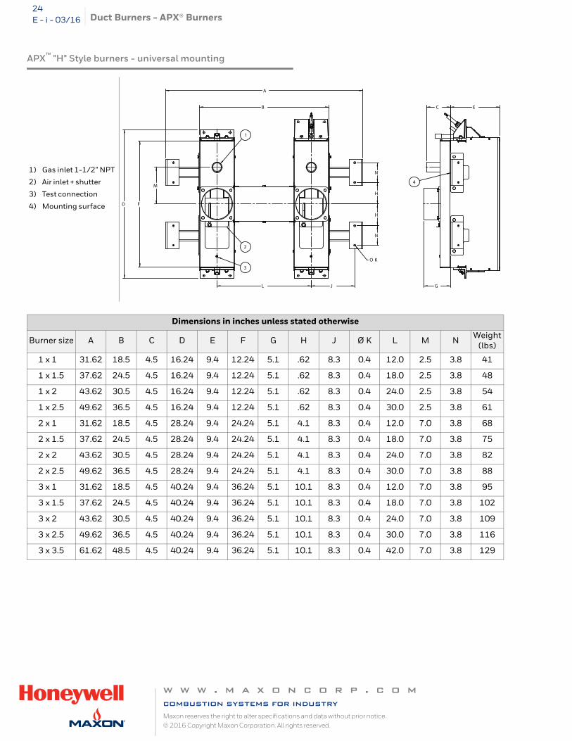
APX™ "H" Style burners - universal mounting
1) Gas inlet 1-1/2” NPT
2) Air inlet + shutter
3) Test connection
4) Mounting surface
Dimensions in inches unless stated otherwise
Burner size A B C D E F G H J Ø K L M N Weight (lbs)
1 x 1 31.62 18.5 4.5 16.24 9.4 12.24 5.1 .62 8.3 0.4 12.0 2.5 3.8 41
1 x 1.5 37.62 24.5 4.5 16.24 9.4 12.24 5.1 .62 8.3 0.4 18.0 2.5 3.8 48
1 x 2 43.62 30.5 4.5 16.24 9.4 12.24 5.1 .62 8.3 0.4 24.0 2.5 3.8 54
1 x 2.5 49.62 36.5 4.5 16.24 9.4 12.24 5.1 .62 8.3 0.4 30.0 2.5 3.8 61
2 x 1 31.62 18.5 4.5 28.24 9.4 24.24 5.1 4.1 8.3 0.4 12.0 7.0 3.8 68
2 x 1.5 37.62 24.5 4.5 28.24 9.4 24.24 5.1 4.1 8.3 0.4 18.0 7.0 3.8 75
2 x 2 43.62 30.5 4.5 28.24 9.4 24.24 5.1 4.1 8.3 0.4 24.0 7.0 3.8 82
2 x 2.5 49.62 36.5 4.5 28.24 9.4 24.24 5.1 4.1 8.3 0.4 30.0 7.0 3.8 88
3 x 1 31.62 18.5 4.5 40.24 9.4 36.24 5.1 10.1 8.3 0.4 12.0 7.0 3.8 95
3 x 1.5 37.62 24.5 4.5 40.24 9.4 36.24 5.1 10.1 8.3 0.4 18.0 7.0 3.8 102
3 x 2 43.62 30.5 4.5 40.24 9.4 36.24 5.1 10.1 8.3 0.4 24.0 7.0 3.8 109
3 x 2.5 49.62 36.5 4.5 40.24 9.4 36.24 5.1 10.1 8.3 0.4 30.0 7.0 3.8 116
3 x 3.5 61.62 48.5 4.5 40.24 9.4 36.24 5.1 10.1 8.3 0.4 42.0 7.0 3.8 129
1
2
3
4
A
B C E
D F
G
H
H
N
N
J
O K
L
M
w w w . m a x o n c o r p . c o mcombustion systems for industryMaxon reserves the right to alter specifications and data without prior notice. © 2016 Copyright Maxon Corporation. All rights reserved.
Duct Burners - APX® Burners 25E - i - 03/16
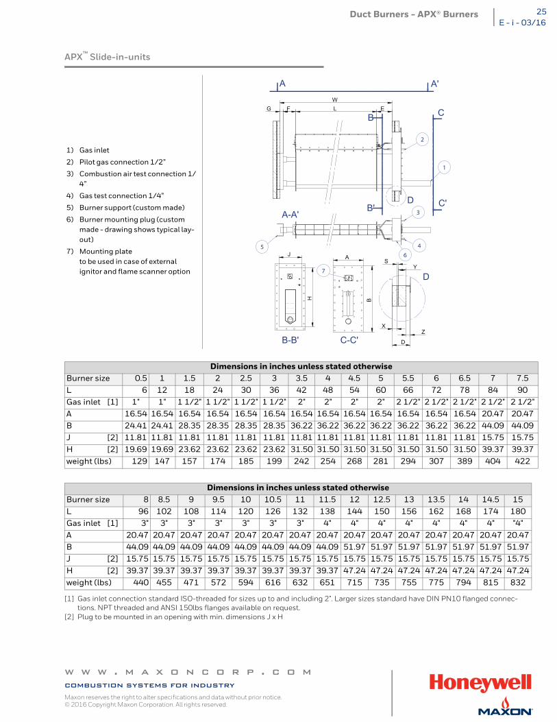
APX™ Slide-in-units
[1] Gas inlet connection standard ISO-threaded for sizes up to and including 2". Larger sizes standard have DIN PN10 flanged connec-tions. NPT threaded and ANSI 150lbs flanges available on request.
[2] Plug to be mounted in an opening with min. dimensions J x H
1) Gas inlet
2) Pilot gas connection 1/2”
3) Combustion air test connection 1/4”
4) Gas test connection 1/4”
5) Burner support (custom made)
6) Burner mounting plug (custom made - drawing shows typical lay-out)
7) Mounting plate to be used in case of external ignitor and flame scanner option
Dimensions in inches unless stated otherwiseBurner size 0.5 1 1.5 2 2.5 3 3.5 4 4.5 5 5.5 6 6.5 7 7.5L 6 12 18 24 30 36 42 48 54 60 66 72 78 84 90Gas inlet [1] 1" 1" 1 1/2" 1 1/2" 1 1/2" 1 1/2" 2" 2" 2" 2" 2 1/2" 2 1/2" 2 1/2" 2 1/2" 2 1/2"A 16.54 16.54 16.54 16.54 16.54 16.54 16.54 16.54 16.54 16.54 16.54 16.54 16.54 20.47 20.47B 24.41 24.41 28.35 28.35 28.35 28.35 36.22 36.22 36.22 36.22 36.22 36.22 36.22 44.09 44.09J [2] 11.81 11.81 11.81 11.81 11.81 11.81 11.81 11.81 11.81 11.81 11.81 11.81 11.81 15.75 15.75H [2] 19.69 19.69 23.62 23.62 23.62 23.62 31.50 31.50 31.50 31.50 31.50 31.50 31.50 39.37 39.37weight (lbs) 129 147 157 174 185 199 242 254 268 281 294 307 389 404 422
Dimensions in inches unless stated otherwiseBurner size 8 8.5 9 9.5 10 10.5 11 11.5 12 12.5 13 13.5 14 14.5 15L 96 102 108 114 120 126 132 138 144 150 156 162 168 174 180Gas inlet [1] 3" 3" 3" 3" 3" 3" 3" 4" 4" 4" 4" 4" 4" 4" "4"A 20.47 20.47 20.47 20.47 20.47 20.47 20.47 20.47 20.47 20.47 20.47 20.47 20.47 20.47 20.47B 44.09 44.09 44.09 44.09 44.09 44.09 44.09 44.09 51.97 51.97 51.97 51.97 51.97 51.97 51.97J [2] 15.75 15.75 15.75 15.75 15.75 15.75 15.75 15.75 15.75 15.75 15.75 15.75 15.75 15.75 15.75H [2] 39.37 39.37 39.37 39.37 39.37 39.37 39.37 39.37 47.24 47.24 47.24 47.24 47.24 47.24 47.24weight (lbs) 440 455 471 572 594 616 632 651 715 735 755 775 794 815 832
A A'
B
B'
C
C'D
WE LFG
Z
D
J
H
S
X
Y
A
B
C-C'
D
B-B'
A-A'
2
1
3
4
65
7
w w w . m a x o n c o r p . c o mcombustion systems for industryMaxon reserves the right to alter specifications and data without prior notice. © 2016 Copyright Maxon Corporation. All rights reserved.
Duct Burners - APX® Burners26E - i - 03/16
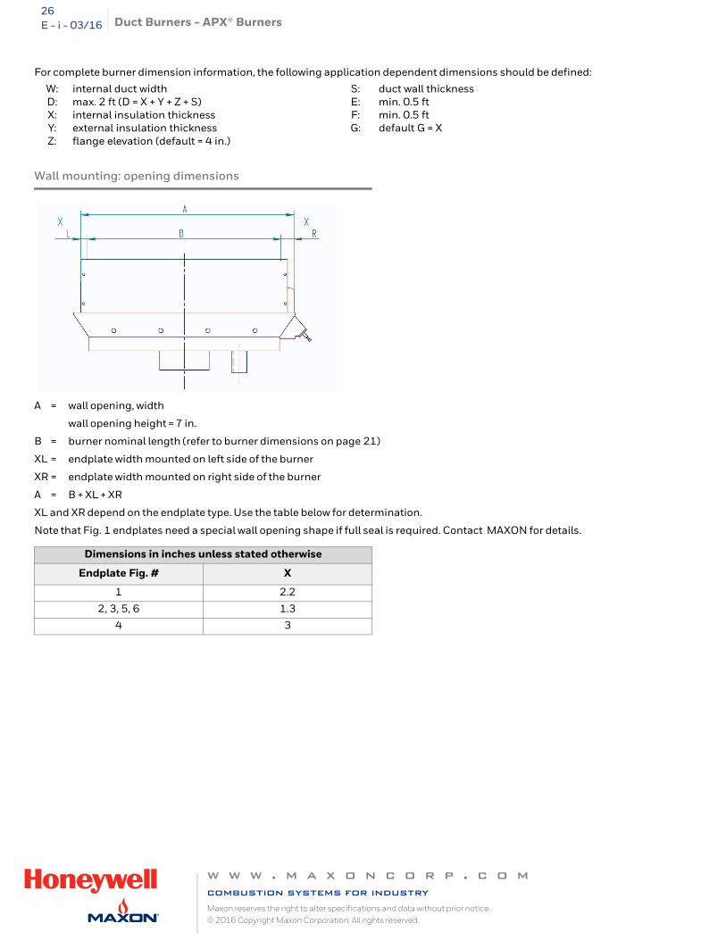
For complete burner dimension information, the following application dependent dimensions should be defined:
Wall mounting: opening dimensions
A = wall opening, width
wall opening height = 7 in.
B = burner nominal length (refer to burner dimensions on page 21)
XL = endplate width mounted on left side of the burner
XR = endplate width mounted on right side of the burner
A = B + XL + XR
XL and XR depend on the endplate type. Use the table below for determination.
Note that Fig. 1 endplates need a special wall opening shape if full seal is required. Contact MAXON for details.
W: internal duct width S: duct wall thicknessD: max. 2 ft (D = X + Y + Z + S) E: min. 0.5 ftX: internal insulation thickness F: min. 0.5 ftY: external insulation thickness G: default G = XZ: flange elevation (default = 4 in.)
Dimensions in inches unless stated otherwise
Endplate Fig. # X
1 2.2
2, 3, 5, 6 1.3
4 3
w w w . m a x o n c o r p . c o mcombustion systems for industryMaxon reserves the right to alter specifications and data without prior notice. © 2016 Copyright Maxon Corporation. All rights reserved.
Duct Burners - APX® Burners 27E - i - 03/16
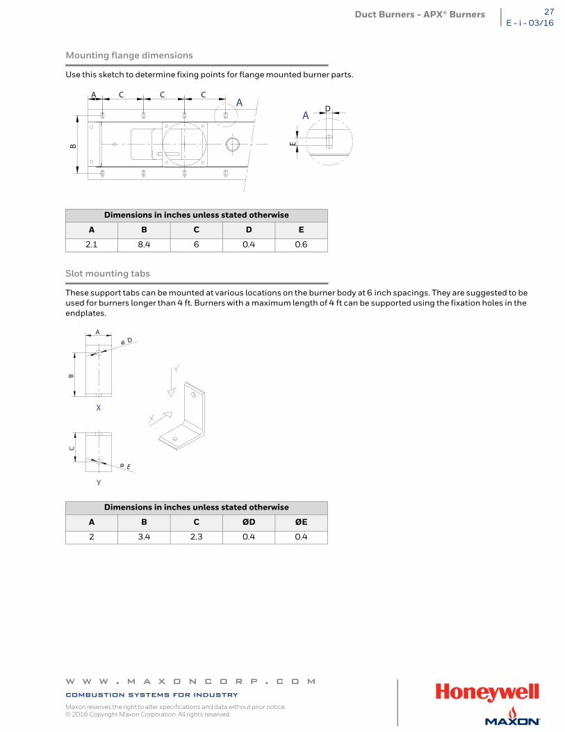
Mounting flange dimensions
Use this sketch to determine fixing points for flange mounted burner parts.
Slot mounting tabs
These support tabs can be mounted at various locations on the burner body at 6 inch spacings. They are suggested to be used for burners longer than 4 ft. Burners with a maximum length of 4 ft can be supported using the fixation holes in the endplates.
Dimensions in inches unless stated otherwise
A B C D E
2.1 8.4 6 0.4 0.6
Dimensions in inches unless stated otherwise
A B C ØD ØE
2 3.4 2.3 0.4 0.4
A C C C
B
D
E
A A
B
A
ø D
C
ø E
X
Y
w w w . m a x o n c o r p . c o mcombustion systems for industryMaxon reserves the right to alter specifications and data without prior notice. © 2016 Copyright Maxon Corporation. All rights reserved.
Duct Burners - APX® Burners28E - i - 03/16
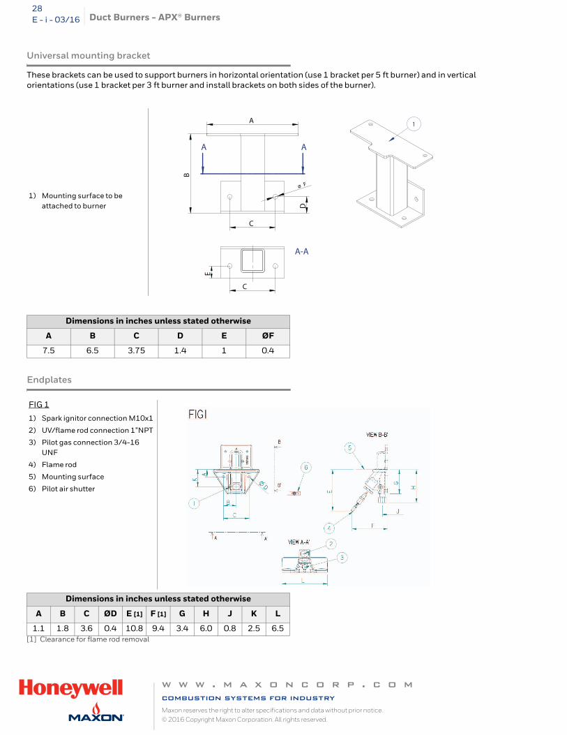
Universal mounting bracket
These brackets can be used to support burners in horizontal orientation (use 1 bracket per 5 ft burner) and in vertical orientations (use 1 bracket per 3 ft burner and install brackets on both sides of the burner).
Endplates
[1] Clearance for flame rod removal
1) Mounting surface to be attached to burner
Dimensions in inches unless stated otherwise
A B C D E ØF
7.5 6.5 3.75 1.4 1 0.4
FIG 1
1) Spark ignitor connection M10x1
2) UV/flame rod connection 1”NPT
3) Pilot gas connection 3/4-16 UNF
4) Flame rod
5) Mounting surface
6) Pilot air shutter
Dimensions in inches unless stated otherwise
A B C ØD E [1] F [1] G H J K L
1.1 1.8 3.6 0.4 10.8 9.4 3.4 6.0 0.8 2.5 6.5
1
AA
C
C
D
ø FB
E
A
A-A
w w w . m a x o n c o r p . c o mcombustion systems for industryMaxon reserves the right to alter specifications and data without prior notice. © 2016 Copyright Maxon Corporation. All rights reserved.
Duct Burners - APX® Burners 29E - i - 03/16
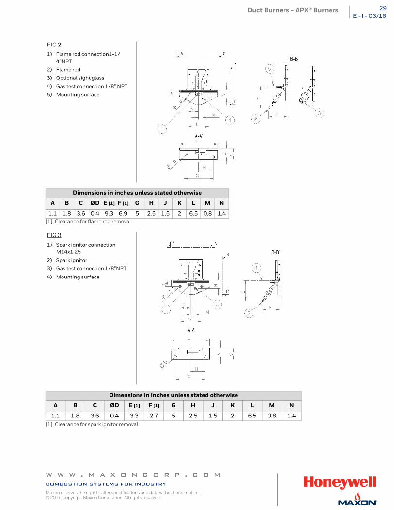
[1] Clearance for flame rod removal
[1] Clearance for spark ignitor removal
FIG 2
1) Flame rod connection1-1/4”NPT
2) Flame rod
3) Optional sight glass
4) Gas test connection 1/8” NPT
5) Mounting surface
Dimensions in inches unless stated otherwise
A B C ØD E [1] F [1] G H J K L M N
1.1 1.8 3.6 0.4 9.3 6.9 5 2.5 1.5 2 6.5 0.8 1.4
FIG 3
1) Spark ignitor connection M14x1.25
2) Spark ignitor
3) Gas test connection 1/8”NPT
4) Mounting surface
Dimensions in inches unless stated otherwise
A B C ØD E [1] F [1] G H J K L M N
1.1 1.8 3.6 0.4 3.3 2.7 5 2.5 1.5 2 6.5 0.8 1.4
w w w . m a x o n c o r p . c o mcombustion systems for industryMaxon reserves the right to alter specifications and data without prior notice. © 2016 Copyright Maxon Corporation. All rights reserved.
Duct Burners - APX® Burners30E - i - 03/16
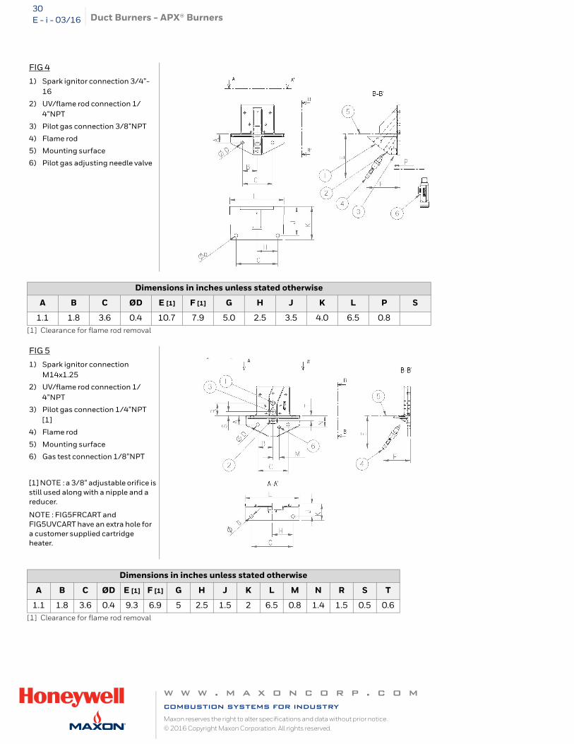
[1] Clearance for flame rod removal
[1] Clearance for flame rod removal
FIG 4
1) Spark ignitor connection 3/4”-16
2) UV/flame rod connection 1/4”NPT
3) Pilot gas connection 3/8”NPT
4) Flame rod
5) Mounting surface
6) Pilot gas adjusting needle valve
Dimensions in inches unless stated otherwise
A B C ØD E [1] F [1] G H J K L P S
1.1 1.8 3.6 0.4 10.7 7.9 5.0 2.5 3.5 4.0 6.5 0.8
FIG 5
1) Spark ignitor connection M14x1.25
2) UV/flame rod connection 1/4”NPT
3) Pilot gas connection 1/4”NPT [1]
4) Flame rod
5) Mounting surface
6) Gas test connection 1/8”NPT
[1] NOTE : a 3/8” adjustable orifice is still used along with a nipple and a reducer.
NOTE : FIG5FRCART and FIG5UVCART have an extra hole for a customer supplied cartridge heater.
Dimensions in inches unless stated otherwise
A B C ØD E [1] F [1] G H J K L M N R S T
1.1 1.8 3.6 0.4 9.3 6.9 5 2.5 1.5 2 6.5 0.8 1.4 1.5 0.5 0.6
w w w . m a x o n c o r p . c o mcombustion systems for industryMaxon reserves the right to alter specifications and data without prior notice. © 2016 Copyright Maxon Corporation. All rights reserved.
Duct Burners - APX® Burners 31E - i - 03/16
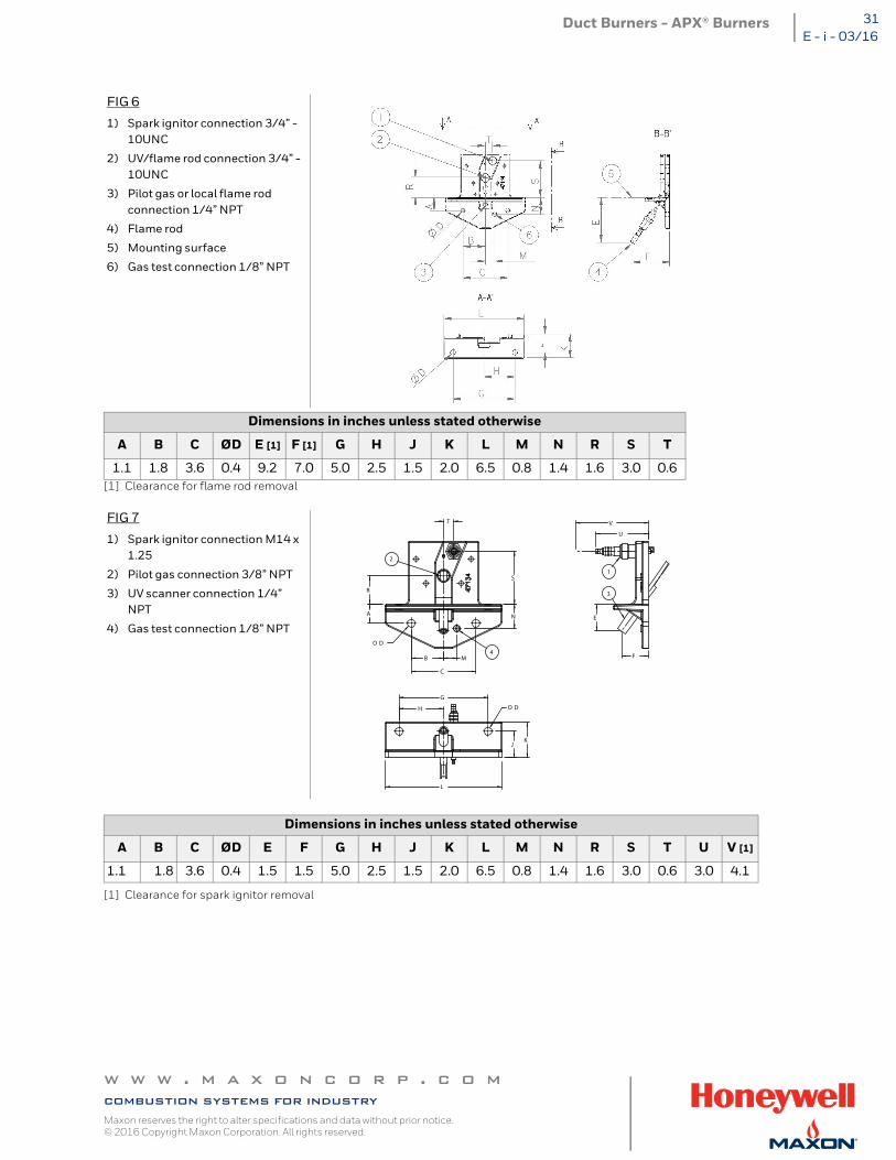
[1] Clearance for flame rod removal
[1] Clearance for spark ignitor removal
FIG 6
1) Spark ignitor connection 3/4” - 10UNC
2) UV/flame rod connection 3/4” - 10UNC
3) Pilot gas or local flame rod connection 1/4” NPT
4) Flame rod
5) Mounting surface
6) Gas test connection 1/8” NPT
Dimensions in inches unless stated otherwise
A B C ØD E [1] F [1] G H J K L M N R S T
1.1 1.8 3.6 0.4 9.2 7.0 5.0 2.5 1.5 2.0 6.5 0.8 1.4 1.6 3.0 0.6
FIG 7
1) Spark ignitor connection M14 x 1.25
2) Pilot gas connection 3/8” NPT
3) UV scanner connection 1/4” NPT
4) Gas test connection 1/8” NPT
Dimensions in inches unless stated otherwise
A B C ØD E F G H J K L M N R S T U V [1]
1.1 1.8 3.6 0.4 1.5 1.5 5.0 2.5 1.5 2.0 6.5 0.8 1.4 1.6 3.0 0.6 3.0 4.1
2
3
4
1
U
V
F
E
M
N
S
JK
H
G
T
O D
A
R
B
O D
C
L
w w w . m a x o n c o r p . c o mcombustion systems for industryMaxon reserves the right to alter specifications and data without prior notice. © 2016 Copyright Maxon Corporation. All rights reserved.
Duct Burners - APX® Burners32E - i - 03/16
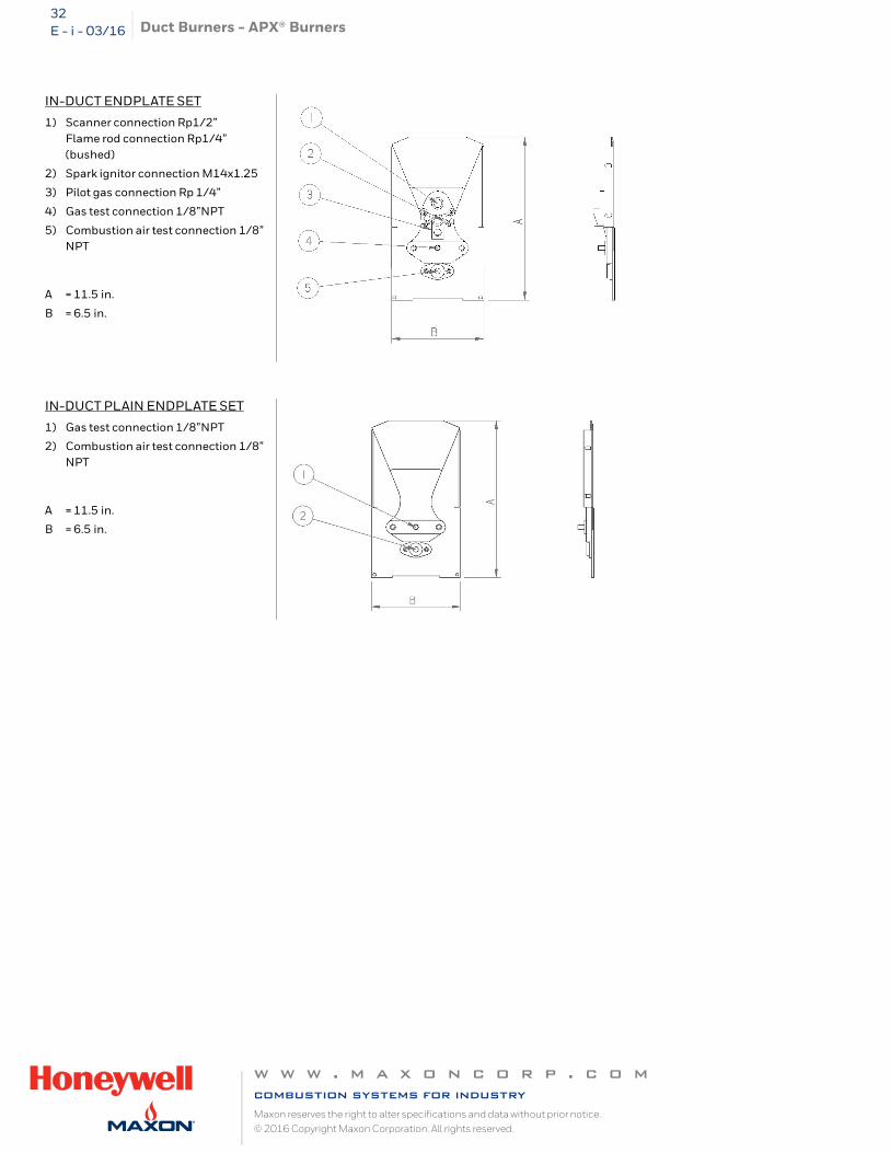
IN-DUCT ENDPLATE SET
1) Scanner connection Rp1/2”Flame rod connection Rp1/4” (bushed)
2) Spark ignitor connection M14x1.25
3) Pilot gas connection Rp 1/4”
4) Gas test connection 1/8”NPT
5) Combustion air test connection 1/8” NPT
A = 11.5 in.
B = 6.5 in.
IN-DUCT PLAIN ENDPLATE SET
1) Gas test connection 1/8”NPT
2) Combustion air test connection 1/8” NPT
A = 11.5 in.
B = 6.5 in.
w w w . m a x o n c o r p . c o mcombustion systems for industryMaxon reserves the right to alter specifications and data without prior notice. © 2016 Copyright Maxon Corporation. All rights reserved.
Duct Burners - APX® Burners 33E - i - 03/16
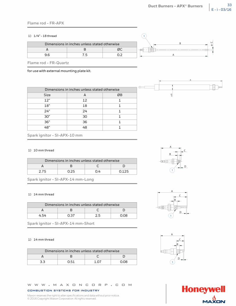
Flame rod - FR-APX
Flame rod - FR-Quartz
for use with external mounting plate kit.
Spark ignitor - SI-APX-10 mm
Spark ignitor - SI-APX-14 mm-Long
Spark ignitor - SI-APX-14 mm-Short
1) 1/4” - 18 thread
Dimensions in inches unless stated otherwise
A B ØC
9.6 7.5 0.2
Dimensions in inches unless stated otherwise
Size A ØB
12” 12 1
18” 18 1
24” 24 1
30” 30 1
36” 36 1
48” 48 1
1) 10 mm thread
Dimensions in inches unless stated otherwise
A B C D
2.75 0.25 0.4 0.125
1) 14 mm thread
Dimensions in inches unless stated otherwise
A B C D
4.54 0.37 2.5 0.08
1) 14 mm thread
Dimensions in inches unless stated otherwise
A B C D
3.3 0.51 1.07 0.08
1
ø CB
A
A
øB
1
A
B
D
C
1
B
D
A
C
1
B
C
D
A
w w w . m a x o n c o r p . c o mcombustion systems for industryMaxon reserves the right to alter specifications and data without prior notice. © 2016 Copyright Maxon Corporation. All rights reserved.
Duct Burners - APX® Burners34E - i - 03/16
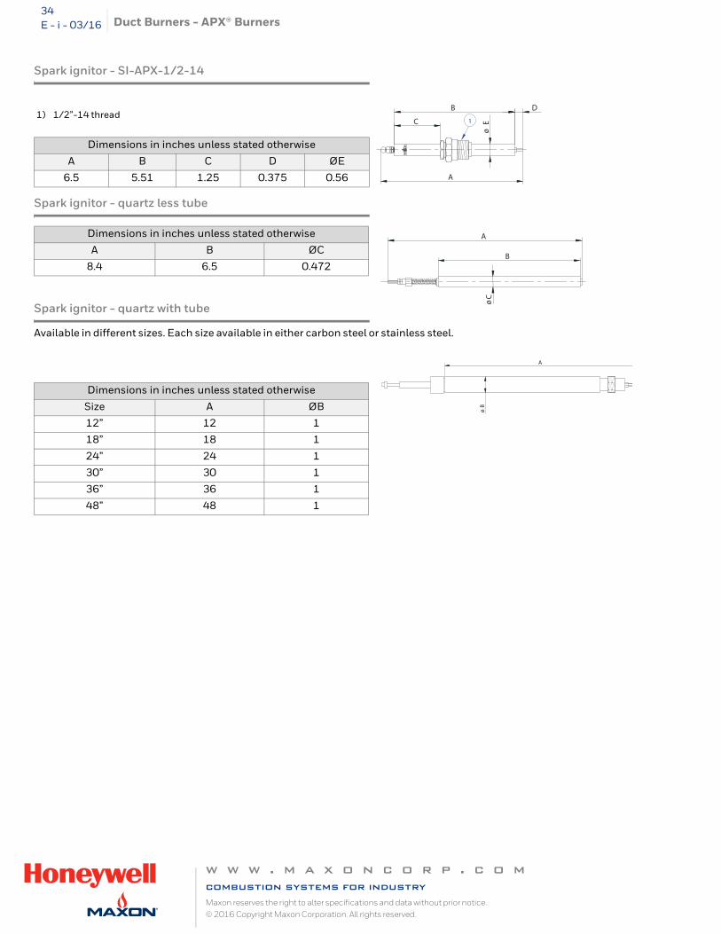
Spark ignitor - SI-APX-1/2-14
Spark ignitor - quartz less tube
Spark ignitor - quartz with tube
Available in different sizes. Each size available in either carbon steel or stainless steel.
1) 1/2”-14 thread
Dimensions in inches unless stated otherwise
A B C D ØE
6.5 5.51 1.25 0.375 0.56
Dimensions in inches unless stated otherwise
A B ØC
8.4 6.5 0.472
Dimensions in inches unless stated otherwise
Size A ØB
12” 12 1
18” 18 1
24” 24 1
30” 30 1
36” 36 1
48” 48 1
A
B D
C
ø E1
B
ø C
A
A
øB
w w w . m a x o n c o r p . c o mcombustion systems for industryMaxon reserves the right to alter specifications and data without prior notice. © 2016 Copyright Maxon Corporation. All rights reserved.
Duct Burners - APX® Burners 35E - i - 03/16
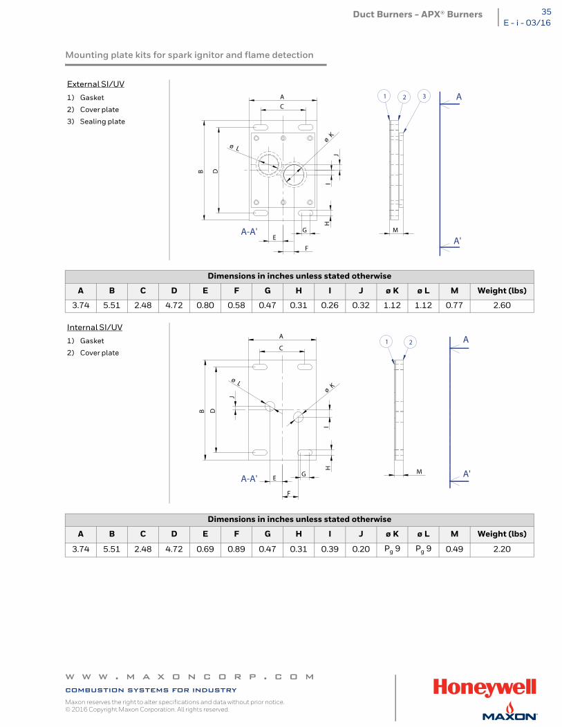
Mounting plate kits for spark ignitor and flame detection
External SI/UV
1) Gasket
2) Cover plate
3) Sealing plate
Dimensions in inches unless stated otherwise
A B C D E F G H I J ø K ø L M Weight (lbs)
3.74 5.51 2.48 4.72 0.80 0.58 0.47 0.31 0.26 0.32 1.12 1.12 0.77 2.60
Internal SI/UV
1) Gasket
2) Cover plate
Dimensions in inches unless stated otherwise
A B C D E F G H I J ø K ø L M Weight (lbs)
3.74 5.51 2.48 4.72 0.69 0.89 0.47 0.31 0.39 0.20 Pg 9 Pg 9 0.49 2.20
1 2 3 A
A'A-A'
DB
C
A
G
HI
J
E
F
ø Lø
K
M
1 2 A
A'A-A' E
J
I
F
MG
H
ø Kø L
DB
C
A
w w w . m a x o n c o r p . c o mcombustion systems for industryMaxon reserves the right to alter specifications and data without prior notice. © 2016 Copyright Maxon Corporation. All rights reserved.
Duct Burners - APX® Burners36E - i - 03/16
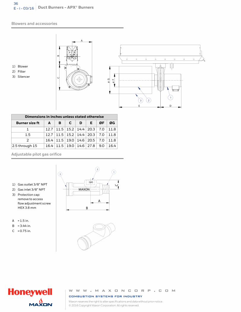
Blowers and accessories
Adjustable pilot gas orifice
1) Blower
2) Filter
3) Silencer
Dimensions in inches unless stated otherwise
Burner size ft A B C D E ØF ØG
1 12.7 11.5 15.2 14.4 20.3 7.0 11.8
1.5 12.7 11.5 15.2 14.4 20.3 7.0 11.8
2 16.4 11.5 19.0 14.6 20.5 7.0 11.8
2.5 through 15 16.4 11.5 19.0 14.6 27.8 9.0 16.4
1) Gas outlet 3/8” NPT
2) Gas inlet 3/8” NPT
3) Protection cap: remove to access flow adjustment screw HEX 3.8 mm
A = 1.5 in.
B = 3.44 in.
C = 0.75 in.
123
A
BC
DE
ø F
ø G
21
3
MAXON
GAS
A
C
B
w w w . m a x o n c o r p . c o mcombustion systems for industryMaxon reserves the right to alter specifications and data without prior notice. © 2016 Copyright Maxon Corporation. All rights reserved.
Duct Burners - APX® Burners 37E - i - 03/16
Installation and operating instructions
Application requirements
View Port
A view port to inspect burner flame is essential to inspect flame aspect. It is recommended to install the view port downstream of the flame, such that the entire burner front can be observed, as well as the pilot burner.
Required ancillary equipment
Ensure that all required ancillary equipment for safe operation and correct performance of the APX™ burner is installed as described in the applicable codes and/or process-related instructions.
Position of the burner in the process flow
MAXON APX™ burners are designed for heating of a process flow in motion. Refer to table page 9 for minimum required process air velocity for in-duct and wall-mounted APX™ burners.
In-duct APX™ burners should be mounted so as to direct their flames parallel to and in the same direction as the movement of the process flow.
Wall mounted burners can be mounted perpendicular to the process flow, as long as the minimum and maximum velocities as indicated in table page 9 are respected. Too high velocities may result in diverged flame patterns, damaging combustion chamber or oven walls.
In both cases, the process flow upstream of the burner should be uniform (maximum deviation of velocity of approx. 20% in 90% of the points of a plane immediately in front of the burners).
Combustion chamber
APX™ burners may have in specific operating conditions (low oxygen or inert process air flows) quite luminous and radiant flames.
Special attention should be paid to the part of the duct covering the flame (combustion chamber). Especially in narrow ducts with flames close to the wall, it is essential to use correct materials and proper construction designs. Contact MAXON for more information.
w w w . m a x o n c o r p . c o mcombustion systems for industryMaxon reserves the right to alter specifications and data without prior notice. © 2016 Copyright Maxon Corporation. All rights reserved.
Duct Burners - APX® Burners38E - i - 03/16
Installation instructions
Storage
APX™ burners should be stored dry (inside). Prevent that water and/or dust can penetrate into the burner manifold during storage.
Handling
APX™ burners are shipped as complete units. Handle the burner with care during unpacking, transport, lifting and installation. Use proper equipment. Any impact on the burner could result in damage.
Remove all plastic caps closing off gas and air connections of the burner prior to connecting it with the pipe-train and combustion air fan.
Orientation
APX™ burners can be mounted in any orientation (firing horizontally / vertically down and upwards).
Mounting
APX™ burners are equipped with a continuous mounting flange or with mounting tabs (see drawings on page 26 and page 27). Bolt the burner with this flange or mounting tabs onto the oven or duct. Tighten the bolts with correct torque and retighten all bolts after first firing and regularly after commissioning. Since wall-mounted APX™ burners are foreseen to operate under suction or in balanced atmospheres, the use of gaskets is not absolutely required, however not prohibited.
Standard in-duct APX™ burners (ID-PB & ID-EB) are hung in the duct with the mounting tabs as shown on drawings page 23 and page 27.
In-duct plug & play burners are equipped with a mounting plate or plug (see drawings page 25 and page 27). Bolt this mounting plug or plate onto the combustion chamber's mounting flange. Use proper gasket (available as an option). Tighten the bolts with correct torque and retighten all bolts after first firing and regularly after commissioning.
Use only the APX™ burner support supplied by MAXON for supporting the burner at the opposite side of the mounting plate/plug. This support is especially designed to give the burner sufficient flexibility during firing. Use of different kind of supports may damage or destroy the burner.
Refer to drawings on page 23 and page 25 for correct position of the burner support.
Hot surfaces
Burner parts in contact with the flame will become hot. Always wait for the burner system to cool down before cleaning.
In specific installations and/or operation modes, some accessible parts of the burner outside the oven or duct may become hot. If required, precautions should be taken to prevent burning injuries by contact with hot surfaces.
w w w . m a x o n c o r p . c o mcombustion systems for industryMaxon reserves the right to alter specifications and data without prior notice. © 2016 Copyright Maxon Corporation. All rights reserved.
Duct Burners - APX® Burners 39E - i - 03/16
Start-up instructions
Instructions provided by the company or individual responsible for the manufacture and/or overall installa-tion of a complete system incorporating MAXON burners take precedence over the installation and operat-ing instructions provided by MAXON. If any of the instructions provided by MAXON are in conflict with local codes or regulations, please contact MAXON before initial start-up of equipment.
Safety interlocks
Guarantee that all the required safety locks as described in the applicable local codes or regulations, or supplementary requested for safe operation of the overall installation, are working properly and resulting in a positive safety-lock of the burner. Do not bypass any of these safety interlocks. This will result in unsafe operation.
Checks during and after start-up
During and after start-up, check the integrity of the system. Check all bolted connections after first firing (first time on temperature) and retighten if necessary.
Purge
For safety reasons, it is required to purge the installation sufficiently long enough to ensure that all possible combustibles are evacuated before ignition. Refer to the applicable local codes and your specific application requirements to determine the purge time.
Pilot ignition
Adjust pilot air flow and pilot gas regulator to correct set point before pilot ignition attempt. Turn adjustable orifice screw out (counter-clockwise) several turns from its fully seated position. Refine during lighting of the pilot to a yellow/blue flame and/or strongest stable flame signal. For FIG1 pilot endplates, note that pilot air may be adjusted for optimal pilot size and ignition by means of a shutter located between the cast iron pilot body and the stainless steel end enclosure plate.
Main burner ignition
Adjust the main gas regulator at the correct set-point before igniting the main burner. Ensure that the gas-air ratio control valve is in the start position when lighting the main burner.
Ratio adjustment
Once the main flame is ignited, adjust air/gas ratio of the burner to obtain the required combustion quality. Slowly increase capacity while observing the flame. Especially observe that the flame is well divided over the entire burner length, and going straight forward in the direction of the process air flow. Check that no damage is caused to duct walls or other equipment.
Read the combustion system manual carefully before initiating the start-up and adjustment procedure. Verify that all of the equipment associated with and necessary to the safe operation of the burner system has been installed correctly, that all pre-commissioning checks have been carried out successfully and that all safety related aspects of the installation are properly addressed.Initial adjustment and light-off should be undertaken only by a trained commissioning engi-neer.
w w w . m a x o n c o r p . c o mcombustion systems for industryMaxon reserves the right to alter specifications and data without prior notice. © 2016 Copyright Maxon Corporation. All rights reserved.
Duct Burners - APX® Burners40E - i - 03/16
Maintenance and inspection
Safety requirements
Regular inspection, testing and recalibration of combustion equipment according to the installation manual is an integral part of its safety. Inspection activities and frequencies shall be carried out as specified in the installation manual.
Perform the following activities at least annually as part of a recommended preventative maintenance routine :
Inspect burner internal parts for wear and oxidation. Inspect associated control instruments and devices for function with particular attention to all safety
permissive switches. Perform leak tests on fuel shut-off valves according to any schedule established by the authority having jurisdiction.
Visual inspections
Regular visual inspection of all connections (air and gas piping to the burner, bolting of the burner mounting flange, burner support in the duct) and burner flame shape and aspect are essential for safe operation.
Recommended spare parts
Keep local stock of spark ignitor and flame detector. It is not recommended to keep local stock of other burner parts. Consult the installation manual for burner system spare parts and accessories.
Other available burner spare parts are:
the mixing plate sets (mixing plate + screws and nuts + back-up bar) gas inlet gasket (gasket between gas inlet flange and burner body) end plate gasket (gasket between endplate and burner body)
w w w . m a x o n c o r p . c o mcombustion systems for industryMaxon reserves the right to alter specifications and data without prior notice. © 2016 Copyright Maxon Corporation. All rights reserved.