Embed Size (px)
Citation preview
BNL-79185-2007-IR
Durability of Very Low Capacity Pressure Atomized Fuel Nozzles Used with Low Firing Rate Residential Oil Burners
Project Report
May 2007
Roger J. McDonald
Prepared for the Building Technologies Program
Office of Energy Efficiency and Renewable Energy United States Department of Energy
Energy Resources Division
Energy Sciences and Technology Department
Brookhaven National Laboratory Brookhaven Science Associates
Upton, NY 11973-5000
Under Contract No. DE-ACO2-98CH10886 with the United States Department of Energy
ii
DISCLAIMER
This report was prepared as an account of work sponsored by an agency of the United States Government. Neither the United States Government nor any agency thereof, nor any of their employees, nor any of their contractors, subcontractors, or their employees makes any warranty, express or implied, or assumes any legal liability or responsibility for the accuracy, completeness, or usefulness of any information, apparatus, product, or process disclosed, or represents that its use would not infringe privately owned rights. Reference herein to any specific commercial product, process, or service by trade name, trademark, manufacturer, or otherwise, does not necessarily constitute or imply its endorsement, recommendation, or favoring by the United States Government or any agency, contractor or subcontractor thereof. The views and opinions of authors expressed herein do not necessarily state or reflect those of the United States Government or any agency, contractor, or subcontractor thereof.
iii
Table of Contents List of Figures .................................................................................................................. iv List of Tables ................................................................................................................... iv Acknowledgements .......................................................................................................... iv Abstract ...............................................................................................................................v 1.0 Introduction- Project Description ................................................................................ 1 2.0 Project Plan .................................................................................................................. 3 3.0 Background on Fuel Oil Atomization and Nozzle Design ........................................... 5 4.0 Description of Equipment, Setup, and Measurement Techniques ............................... 7 5.0 Test Results ................................................................................................................ 10 6.0 Conclusions................................................................................................................. 17
iv
List of Figures Figure 1 Reliability versus firing rate for several nozzle designs ...................................... 1 Figure 2 Simplex pressure nozzle ...................................................................................... 3 Figure 3 Nozzle components, operation ............................................................................ 3 Figure 4 Oil burner nozzle geometry comparisons............................................................. 6 Figure 5 Combustion head and nozzle ............................................................................. 11 Figure 6 Nozzle after 4,650 hours ................................................................................... 11 Figure 7 Nozzle orifice exit .............................................................................................11 Figure 8 Top of fuel distributor cone, 3 slots ................................................................... 11 Figure 9 One of three internal fuel-metering slots ...........................................................12 Figure 10 Nozzle body temperature with the “cooler chamber” during cycling ..............12 Figure 11 Burner and boiler front cover ..........................................................................14 Figure 12 Boiler heavily sooted ........................................................................................14 Figure 13 Burner head and nozzle ..................................................................................14 Figure 14 Nozzle and fuel line assembly ..........................................................................14 Figure 15 Fouled nozzle tip, after 1405 hours of on-time operation ................................15 Figure 16 Nozzle (double) filter, fairly clean, with 1405 hours on-time ..........................15 Figure 17 Metering slot (no blockage), one of three ........................................................16 Figure 18 Slot partially blocked by fuel “varnish” ...........................................................16 Figure 19 Plot of temperature of nozzle body surface temperature, typical of data obtained during 6 ½ month test period in “hot chamber” environment ............................17
List of Tables Table 1 Emissions data for the two units tested ............................................................... 18 Table 2 Approximate (5 minute) steady state gas efficiency.............................................18
Acknowledgements The author would like to acknowledge Yusuf Celebi and George Wei of the BNL team who contributed to the installation of the unit at BNL and the experimental effort. Finally the author would like to acknowledge the support and guidance of Arun Vohra, technical representative overseeing this work for the U.S. Department of Energy, the project sponsor.
v
Abstract Brookhaven National Laboratory (BNL), working for the United States Department of Energy (DOE), has conducted a preliminary evaluation of the potential of very low fuel input capacity Simplex type pressure atomizing nozzles for use with oil burners designed for residential boilers, furnaces and water heaters. These nozzles under suitable conditions can be sufficiently reliable to enable new heating system designs. This would allow for the design of heating appliances that match the smaller load demands of energy efficient homes built with modern components and architectural systems designed to minimize energy use. When heating systems are installed with excessive capacity, oversized by three to four times the load, the result is a loss of up to ten percent as compared to the rated appliance efficiency. The use of low capacity nozzles in systems designed to closely match the load can thereby result in significant energy savings. BNL investigated the limitations of low flow rate nozzles and designed long-term experiments to see if ways could be determined that would be beneficial to long-term operation at low input capacities without failures. In order to maximize the potential for success the best possible industry practices available were employed. Low flow rate nozzles primarily fail by blockage or partial blockage of internal fuel flow passages inside the nozzle. To prevent any contaminants from entering the nozzle BNL investigated the geometry and critical dimensions and the current sate of the art of fuel filter design. Based on this investigation it was concluded that the best available filters should be more than capable of filtering contaminants from the fuel prior to entering the oil burner itself. This position was indeed validated based on the long-term trials conducted under this study no evidence resulted to change our position. It is highly recommended that these filters rated at 10 microns and with large filter capacity (surface area), should be used with all oil burner installations. The other possible failure mode had been attributed to fuel degradation and this became the main focus of the evaluation. The degradation of fuel usually occurs faster under higher temperature conditions. To preclude this as much as possible controls that provided for a post-purge of combustion airflow after burner shut down were selected. This provided a short period of time where the burner’s combustion air blower continues to operate after the flame has gone out. This tends to cool the nozzle and in turn the fuel inside the small flow pathways inside the nozzle components. This study concludes that the use of low capacity nozzles is possible but only when the temperature and thermal mass environment of the combustion chamber result in a relatively “cool” condition. This was accomplished in one long-term experiment that essentially operated for a full heating season equivalent with no evidence of nozzle plugging or failure. The nozzle body surface temperature was kept at or below 150 F during the duration of the trial. On the other hand, a second system was studied that ended in a partial nozzle blockage and a system failure. In this “hot environment” system the nozzle body temperature reached 210 F. This occurred at close to a full heating season equivalent, yet it still would have resulted in a no-heat complaint by the homeowner.

vi
1
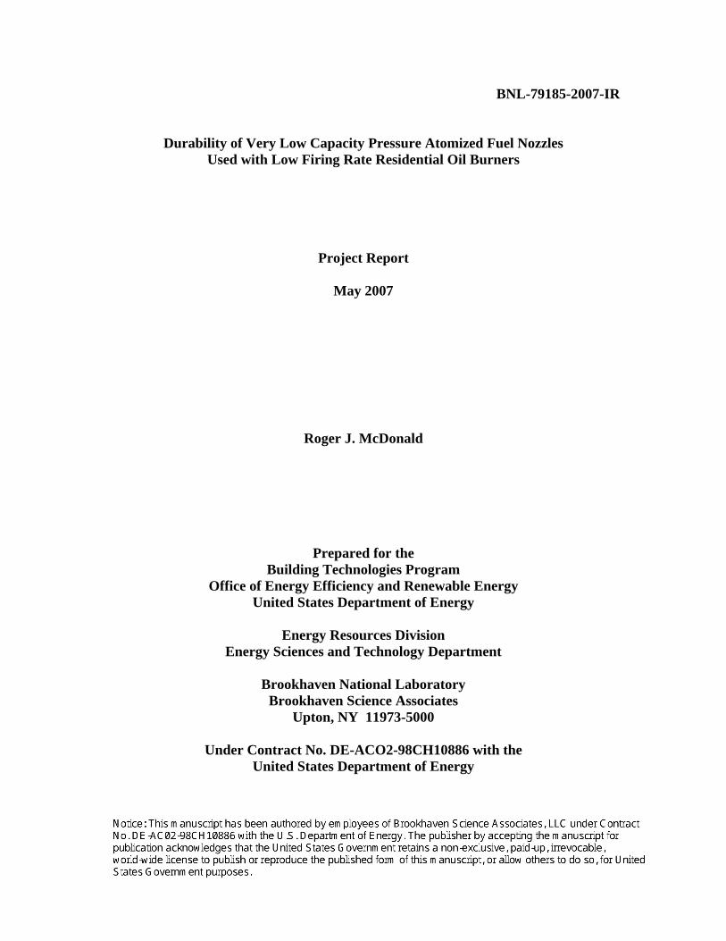
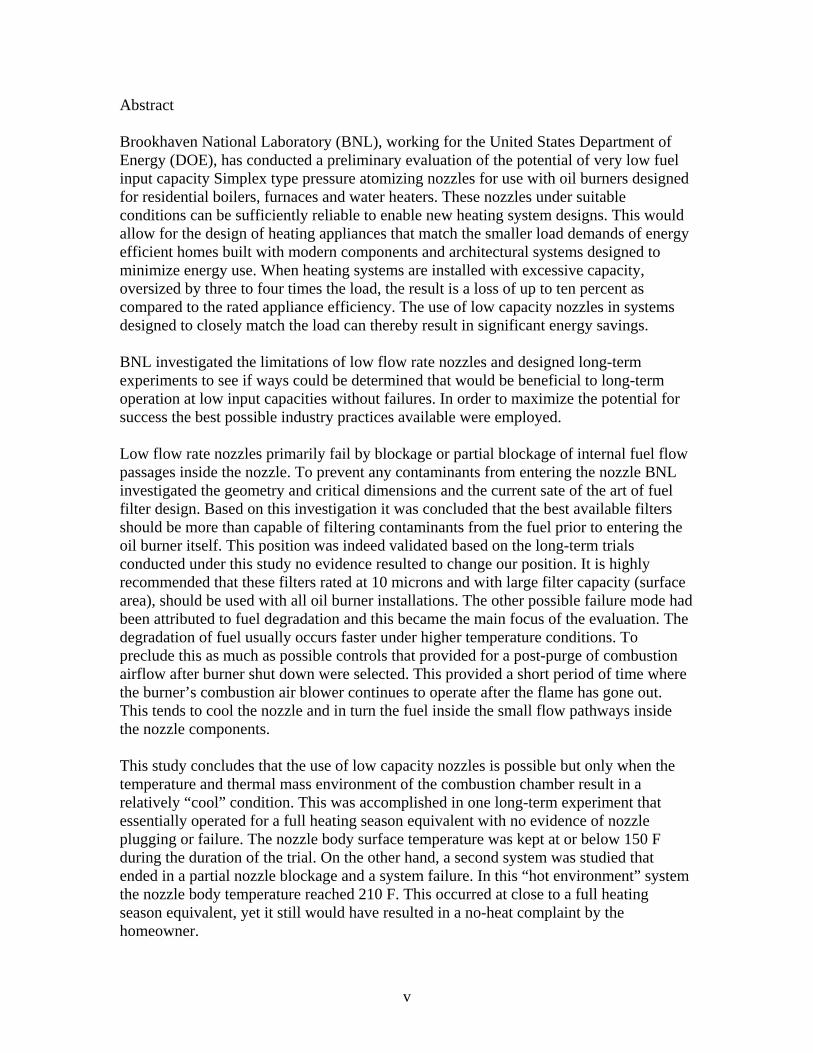
1.0 Introduction- Project Description Brookhaven National Laboratory (BNL), working for the United States Department of Energy (DOE), has conducted a preliminary evaluation of the potential of recently developed lines of very low fuel input capacity Simplex type pressure atomizing nozzles for use with oil burners designed for residential boilers, furnaces and water heaters. These nozzles if found to be sufficiently reliable could be the basis for designing heating appliances that match the smaller load demands of energy efficient homes built with modern components and architectural systems designed to minimize energy use. When heating systems are installed with excessive capacity, oversized by three to four times the load, the result can be a decrease in efficiency of up to ten percent as compared to the rated appliance efficiency. The flame retention head oil burner that uses a pressure atomizing simplex nozzle dominates the residential oil burner market. These burners are operated with a fuel pressure of between 100 and 140 pounds per square inch at rates at or above 0.5 gallon per hour (GPH). The experience of the oilheat industry has been that when nozzles smaller then 0.5 GPH are used they do not provide adequate performance for more then a few months of use. The lack of durability under field conditions causes reliability concerns that negate their use. Unfortunately much of the information on reliability of pressure nozzles at low firing rates is not quantitative but rather based on limited service organization experience. One paper which presents data is: Fey, T., Pulsating oil flow for minimum-capacity oil burners, Proceedings of the First European Conference on Small Burner Technology and Heating Equipment, Zurich Sept. 1996. Included in this paper is a figure, reproduced below, which shows reliability versus firing rate for several nozzles, including the conventional simplex pressure atomizing nozzle.
Figure 1 - Reliability versus firing rate for several nozzle designs, T. Fey 1996
2
Lower firing rate oil burners have been needed for a long time to reduce energy losses and pollutant emissions associated with the high rate or frequency of the burner cycling on and off. This is caused by over designing the burner capacity in comparison to the extraction of heat by the boiler and in turn the home’s thermal distribution that delivers the heat where it’s needed. The same is true for warm air heating systems where the delivery of comfortable heat requires a much smaller input rate of heat at the burner for modern homes designed with energy efficiency in mind. In either case the burner cycles on and off controlled by a high limit temperature set point in the control system. The smallest reliable fuel nozzle is 0.5 GPH or an input rate of 70,000 Btu per hour. In comparison a home might only require 25-35,000 Btu per hour at design conditions (the coldest day of the year) and typically requires 10,000-15,000 Btu per hour for most of the heating season. This becomes increasingly important as home heating loads decrease in new construction. The vast majority of homes are equipped with heating systems that are vastly oversized; these can be 200% to 400% larger than needed. This can be true for many existing homes as well as most that have had some type of retrofit to the building envelope to reduce the heating load. These houses have received energy conservation upgrades related to better insulation, windows, and doors as well as effort to tighten the envelopes using caulking and other means. New homes have even smaller heating requirements if built properly. When taken to the extreme a home in a cold climate might only require an input of 20,000 Btu per hour at design conditions if the builder does everything correctly. The oil-fired heating appliances being marketed have not kept pace with this down sizing in capacity required because it is unable to break the lower limit of 70,000 Btu per hour due to the limitation of nozzle designs. Novel air-atomized and vaporizing burners have been developed, and in some cases commercialized to achieve this goal but high costs have prevented market acceptance. At the same time, manufacturers of pressure-atomized nozzles have been developing lower firing rate nozzles and nozzles with rates as low as 0.25 gallon per hour have recently become available in Europe. The industry has a strong reluctance to use these nozzles because of a perception that they will lead to very high rates of burner failure related to nozzle plugging. Solids in the atomizer typically cause the failure of nozzles but it is not clear how much of this is related to filtration and how much is related to carbon formation due to fuel residue in the nozzle and heat stress following burner shutdown. The goal of this project focuses on addressing the needs of Building America Zero Energy Housing’s and existing homes within the context of the U.S. where oil is primarily used for space heating and DHW. Considering all types of conventional fuels, these end-uses represent nearly 80% of the homeowner’s total energy consumption in the Northeast (EIA 2001). Collectively the Northeast including all of New England, New York, New Jersey and Pennsylvania represents 9 million homes. The region is densely populated, and other sources of energy are either too costly or unavailable. Heating oil will continue to be a viable choice well into the future. There is certainly an interest in meeting these demands of this customer base in delivering the most energy efficient heating products possible.
3
2.0 Project Plan The following project plan has been reproduced from the defining statement of work as proposed to the DOE. The goal of this project focuses on addressing the needs of “Building America Zero Energy Housing” and existing homes within the context of the U.S. where oil is primarily used for space heating and DHW. Considering all types of conventional fuels, these end-uses represent nearly 80% of the homeowner’s total energy consumption in the Northeast (EIA 2001). Collectively the Northeast including all of New England, New York, New Jersey and Pennsylvania represents 9 million homes. The region is densely populated, and other sources of energy are either too costly or unavailable. Heating oil will continue to be a viable choice well into the future. Statement of Work: Project Goal: To achieve significant reductions in fuel use with oil-fired heating systems by achieving a strong technical foundation for the acceptance and use of low capacity firing rates in new oil-fired heating equipment. This will allow for heating products to be developed that will match the heating load requirements of newer efficient residential house designs as well as in existing home that have had major building envelope upgrades to reduce heating load demands. Properly matching input rate to lower loads will reduce energy needs by eliminating the losses and poor efficiency that results from oversized heating systems. Currently this equipment if grossly oversized leading to poor annual efficiency. Objective: To determine if newer designs of low capacity pressure atomizing nozzle are acceptable for long term use in oil-fired appliances, or if not, to identify specific causes of the plugging of these low firing rate nozzles and to evaluate the potential to eliminate these causes through better filtration, burner post purge to cool the nozzle and chamber assembly following shut down, and elimination of high thermal mass refractory combustion chambers which can increase heat radiation back to the nozzle allowing for fuel vaporization and carbon formation. Specific Technical Target: Low Capacity Oil Burners – Demonstration of reliable operation of pressure swirl oil burner atomizers at firing rates as low as 0.25 GPH, achieved through a combination of basic fuel filtration, nozzle temperature control during cyclic operation, and direct fuel shutoff at the nozzle tip following burner shutdown. A long term firing tests (2 months minimum) under cyclic operation will be completed. Task 1 Determination of Low Capacity Oil Burner Nozzle Performance Characteristics A sample of recently developed low flow capacity nozzles (less then 0.5 GPH) will be obtained for evaluation and test firing in oil-fired appliances. Operational characteristics will be logged under standard cyclic operating conditions for a period of time simulating
4
up to a full year of operation or until nozzle failure occurs. The fuel feeds will include both highly effective filters operating well above industry practices in order to isolate the possibility of fuel contaminants clogging the internal nozzle passages and also potentially less effective filters commonly used in the oilheat industry. This will be done for both high and low thermal mass refractory combustion chambers. Operating control effects will be included to determine the effect of heat soak back from the hot combustion chambers to the nozzles and internal passages. Variations of control scenarios include the use or lack of an oil flow delay solenoid value resulting in a post-purge capability or a lack of post-purge (common practice in the industry). The nozzle bodies will be equipped with thermocouples to allow for logging temperatures. The nozzles will be inspected upon failure or after the full year simulation to see if there is evidence of clogging of the critical fuel passages. A presentation at the 2006 Oilheat Visions conference is planned (see Task 3) and will be used to solicit industry feed back on the findings obtained to that point. Milestone: Complete survey of available nozzles, critical flow dimensions, lab study of nozzle temperature profiles during cyclic operation with “hot” and “cold” combustion environments, and reliability in long term cyclic operation ......................................... 8/06 Task 2 Determination of Root Cause of Nozzle Blockage and failure The nozzles will be inspected upon failure or after the full year simulation to see if there is evidence of clogging of the critical fuel passages. The characteristics of the material built up in either the sintered filter or the internal passages like the metering slots of the nozzle will be investigated. The two likely sources are either from the fibers of a filter or more likely the buildup of fuel related varnish and carbon deposition from thermal stresses when the burner shuts off and heat soaks back from the hot combustion chamber. Appropriate measurement tools available at BNL will be deployed depending upon the nature and location of blockage deposits. Milestone: Define key root causes of blockage and solutions ...................................................... 11/06 Task 3 Technical Report and Conference Paper on Low Input Nozzles Prepare a technical report detailing the experiments, findings and recommendations of the study to determine the viability of using low firing rate pressure atomizing nozzles in the range of 0.25 to 0.4 gallons per hour. This report will be the basis for trade journal articles, a conference paper and presentations in efforts to disseminate the findings to the oilheat industry including equipment manufactures, marketers and oil service organization. Deliverables: Presentation on low capacity nozzles for Oilheat Vision Conference........................... 8/06 BNL draft report on low capacity nozzle performance .............................................. 12/06
5
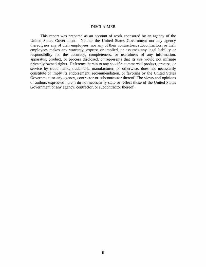
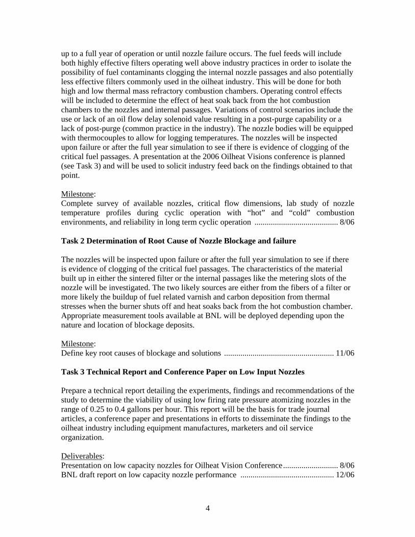
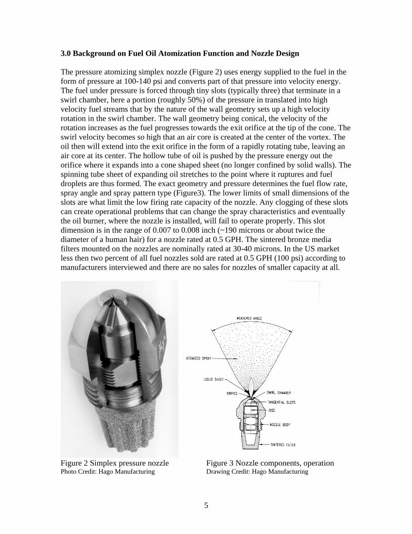
3.0 Background on Fuel Oil Atomization Function and Nozzle Design The pressure atomizing simplex nozzle (Figure 2) uses energy supplied to the fuel in the form of pressure at 100-140 psi and converts part of that pressure into velocity energy. The fuel under pressure is forced through tiny slots (typically three) that terminate in a swirl chamber, here a portion (roughly 50%) of the pressure in translated into high velocity fuel streams that by the nature of the wall geometry sets up a high velocity rotation in the swirl chamber. The wall geometry being conical, the velocity of the rotation increases as the fuel progresses towards the exit orifice at the tip of the cone. The swirl velocity becomes so high that an air core is created at the center of the vortex. The oil then will extend into the exit orifice in the form of a rapidly rotating tube, leaving an air core at its center. The hollow tube of oil is pushed by the pressure energy out the orifice where it expands into a cone shaped sheet (no longer confined by solid walls). The spinning tube sheet of expanding oil stretches to the point where it ruptures and fuel droplets are thus formed. The exact geometry and pressure determines the fuel flow rate, spray angle and spray pattern type (Figure3). The lower limits of small dimensions of the slots are what limit the low firing rate capacity of the nozzle. Any clogging of these slots can create operational problems that can change the spray characteristics and eventually the oil burner, where the nozzle is installed, will fail to operate properly. This slot dimension is in the range of 0.007 to 0.008 inch (~190 microns or about twice the diameter of a human hair) for a nozzle rated at 0.5 GPH. The sintered bronze media filters mounted on the nozzles are nominally rated at 30-40 microns. In the US market less then two percent of all fuel nozzles sold are rated at 0.5 GPH (100 psi) according to manufacturers interviewed and there are no sales for nozzles of smaller capacity at all.
Figure 2 Simplex pressure nozzle Figure 3 Nozzle components, operation Photo Credit: Hago Manufacturing Drawing Credit: Hago Manufacturing
6
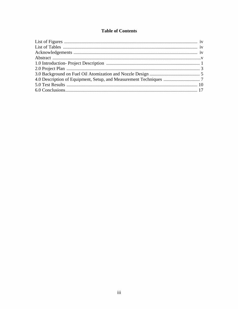
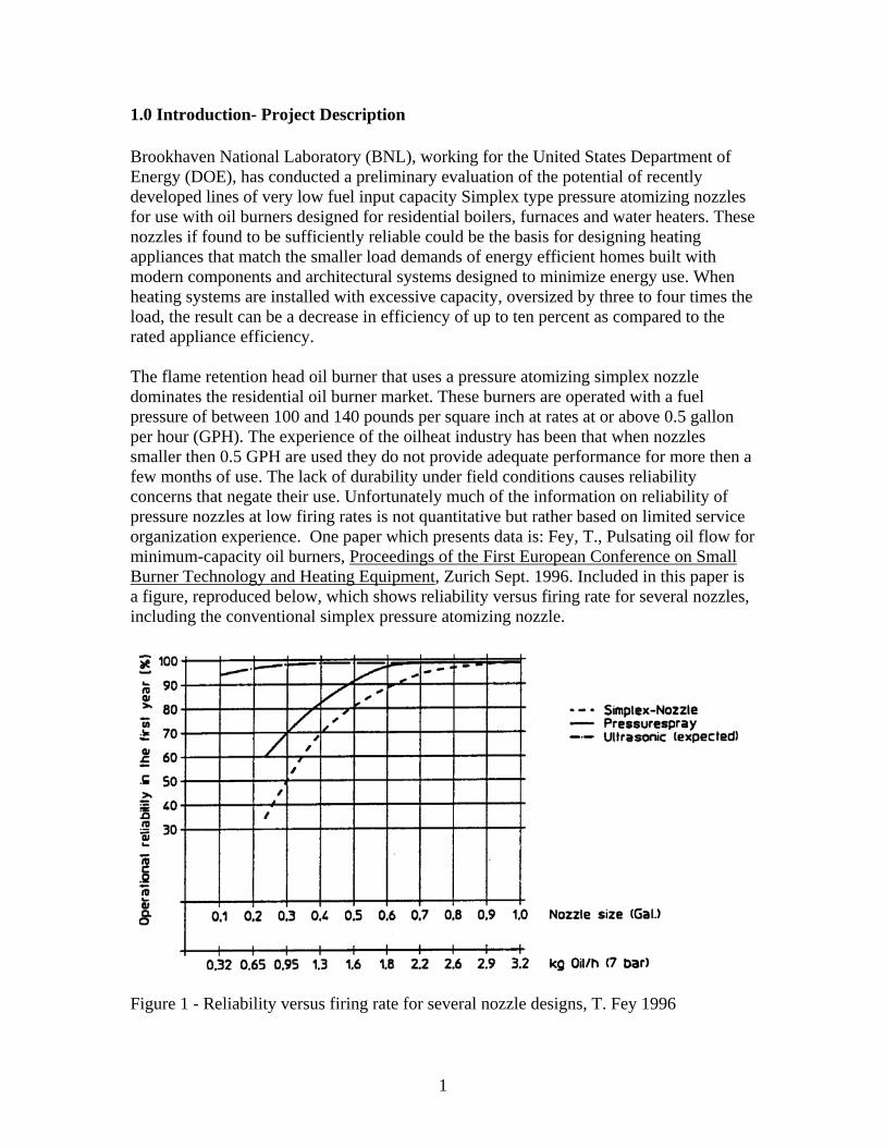
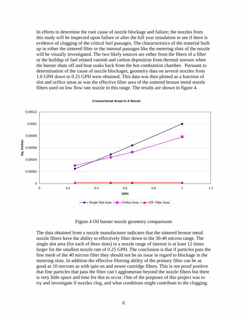
In efforts to determine the root cause of nozzle blockage and failure; the nozzles from this study will be inspected upon failure or after the full year simulation to see if there is evidence of clogging of the critical fuel passages. The characteristics of the material built up in either the sintered filter or the internal passages like the metering slots of the nozzle will be visually investigated. The two likely sources are either from the fibers of a filter or the buildup of fuel related varnish and carbon deposition from thermal stresses when the burner shuts off and heat soaks back from the hot combustion chamber. Pursuant to determination of the cause of nozzle blockages, geometry data on several nozzles from 1.0 GPH down to 0.25 GPH were obtained. This data was then plotted as a function of slot and orifice areas as was the effective filter area of the sintered bronze metal nozzle filters used on low flow rate nozzle in this range. The results are shown in figure 4.
Figure 4 Oil burner nozzle geometry comparisons
The data obtained from a nozzle manufacturer indicates that the sintered bronze metal nozzle filters have the ability to effectively filter down to the 30-40 micron range. The single slot area (for each of three slots) in a nozzle range of interest is at least 12 times larger for the smallest nozzle rate of 0.25 GPH. The conclusion is that if particles pass the fine mesh of the 40 micron filter they should not be an issue in regard to blockage in the metering slots. In addition the effective filtering ability of the primary filter can be as good as 10 microns as with spin on and newer cartridge filters. This is not proof positive that fine particles that pass the filter can’t agglomerate beyond the nozzle filters but there is very little space and time for this to occur. One of the purposes of this project was to try and investigate if nozzles clog, and what conditions might contribute to the clogging.
Crossectional Areas In A Nozzle
0
0.00002
0.00004
0.00006
0.00008
0.0001
0.00012
0 0.2 0.4 0.6 0.8 1 1.2
GPH
Sq. I
nche
s
Single Slot Area Orifice Area Eff. Filter Area
7
4.0 Description of Equipment, Setup, and Measurement Techniques The selections of the test components were constrained by availability. Initially requests were made of several nozzle and oil burner manufacturers. One company responded that it was producing a line of low flow rate nozzles for sale in the European market. The drive for higher efficiencies has created a modest but increasing demand for low flow rate oil burners for use in highly efficient heating system designs. These units have become so small in capacity that their footprints are tiny enough to design wall mounted heating systems. The availability of higher quality oil and advanced fuel pre-heaters may have also contributed to enable the use of lower input rate fuel nozzle in Europe. The nozzle company provided a selection of nozzles below 0.5 GPH all the way down to 0.25 GPH (@ 100 psi). Two oil burner manufacturers also answered our request to provide prototype product designs for use with below 0.5 GPH nozzles. One had a unit available with prototype air tube and end cone and shipped it out upon request. The second promised a burner but this was delayed for several weeks before finally arriving at BNL. Given the limited laboratory space for establishing long term evaluations of these systems while allowing for other projects in the area of oilheat research to continue, a decision was made to evaluate the potential failure mechanisms and to provide the best industry practice to avoid those issues of concern with known solutions. If a nozzle was going to fail it seemed reasonable that it would very likely be due to plugging or partial plugging of the internal fuel passages, namely the very tiny fuel metering slots. These slots are on the order of 6/1000 of an inch or less in the firing range of interest. The assumption being that this was either a result of a buildup of contaminants or degraded fuel, creating varnish like deposits in the slots. The issue of contamination could be resolved based on proper use of modern filtration techniques already available to the oilheat industry. The laboratory evaluation of low flow nozzles eventually consisted of two test stands, each equipped with a boiler and prototype oil burner designed for firing rates below 0.5 GPH. Two boiler designs were selected as test platforms, both units were horizontal axis geometry boilers but with very different combustion chamber characteristics. The first had a cylindrical combustion chamber that utilized a minimum of refractory liner material, essentially a concentric ring, at the end of the boiler where burner was mounted and also a rear target wall. The rest of the chamber is water-backed steel. This geometry provides a relatively “cool environment” with regard to heat reflection or re-radiation of the hot refractory walls on the burner end cone and nozzle components. The second boiler selected uses a fully enclosed combustion chamber that surrounds the flame with a relatively small opening for the hot gases to travel into a very effective heat exchanger. This geometry is a very “hot environment” with the maximum potential for the hot refractory to radiate more heat back towards the burner end cone and nozzle. Either design works well under steady state conditions. In steady state the constant flow of combustion air over the nozzle provides a cooling effect. However, residential heating systems do not operate under steady state conditions. On the contrary, most units cycle on and off literately 25,000 or more times each year. During each cycle the heat built up in
8
the refractory component mass can re-radiate back on to the burner end cone and nozzle and cause them to heat up. The higher the temperature the more likely the fuel in the nozzle will be unstable and begin to degrade. The two boilers selected for this test were as different in this regard as possible to examine the long-term effect on the nozzle’s ability to perform its function as intended. Both units were equipped with the best filters available, described as filtering out most particles greater then 10 microns to try and minimize the possibility of nozzle clogging due to dirt and debris building up in the internal passages. Each test stand utilized the same source of fuel, that being a 1,000-gallon above ground tank that supplies the oilheat test laboratory at BNL. This tank is periodically filled as needed with No. 2 heating oil that is then checked with regard to heating value and sulfur content by sending a sample to an outside fuel testing laboratory. The units tested were installed with a 0.25 GPH rated nozzle form a single manufacturer presumably from the same production run. Based on the burner manufacturer’s recommendations both were set to operate with a fuel pressure of 140 psi, so the actual firing rate was about 0.3 GPH. Each unit was controlled by a programmable repeat cycle timer that turned the burner on for 5 minutes and then off for 10 minutes, over and over again. Each burner was also equipped with a total run time accumulator clock. This was triggered by the operation of the fuel solenoid so that any pre-purge, or post purge period was ignored. This was activated anytime power was applied to the fuel solenoid and fuel was flowing to the burner. The boilers were set up to achieve maximum efficiency within the burners’ ability to operate below the normal firing range. The first burner was designed for firing rate as low as 0.4 GPH and was installed in the boiler with the “cooler” combustion chamber environment. To achieve the best possible efficiency at an input rate of 0.3 GPH an additional air control was required. The burner was adjusted as tightly as possible and then an external air adapter was used equipped with an air gate to further cut down on the excess air. When all air fuel ratio adjustments were completed the system operated with a zero smoke level and on average a carbon dioxide level of 12.2%, an oxygen level of 4.7%, carbon monoxide of 2 ppm, and a nitrogen oxides level of 87 ppm. These measurements were all obtained using a Testo 350 multi-gas analyzer. At these conditions the boiler normally rated at 0.75 GPH was operating at a steady state efficiency of 88.3 % with a stack temperature of 330 F. Initial observations showed that the unit was condensing significantly at the beginning of each burner cycle. This became obvious as condensate was observed dripping out of the bottom of the boiler after the first day of operation. This was expected, as the unit was severely under-fired at this point. The purpose of the test was not to evaluate the boiler performance but rather to see how long the nozzle would continue to operate at this very low capacity under repetitive cycling conditions. After the first two weeks a type K thermocouple was installed at the nozzle body surface just at the point were it is threaded into the nozzle adapter of the oil burner. This was subsequently used to monitor nozzle body temperature during the long-term experiment. The primary oil burner control incorporated a 15-second pre-purge and a one-minute post-purge. This allows the burner motor to come up to speed on startup and a one-minute period to cool down after the burner flame is extinguished. The post purge also has the benefit of helping to cool the
9
nozzle and end cone at the end of each burn cycle. This choice was by design to enhance the probability of success in developing a working strategy that would allow for low oil flow capacity and survival of the nozzle over a full year of operation. After some delay in obtaining a second prototype burner a second test stand was established using the boiler with the “hot” combustion chamber environment. This boiler was installed using a sidewall vent system option, as no space was available in the main test laboratory where it would have otherwise been installed using a masonry chimney. The second unit was set up using the same nozzle size; also at 140 psi with a fuel flow rate of approximately 0.3 GPG. When all air fuel ratio adjustments were completed the system operated with a zero smoke level and on average a carbon dioxide level of 11.3%, an oxygen level of 5.9%, carbon monoxide of 2 ppm, and a nitrogen oxide level of 125 ppm. These measurements were also obtained using the Testo 350 multi-gas analyzer. At these conditions the boiler normally rated at 0.75 GPH was operating at a steady state efficiency of 91.1 % with a stack temperature of 200 F. The second burner installed with the second boiler could not be made to operate with the same air fuel ratio but again was adjusted to a zero smoke level and the carbon dioxide level of 11.3% which was still considered quite good. The second system was equipped with the same level of controls to regulate cycle duration and repeat and instrumentation to monitor nozzle body temperature. The two differences were the “hot environment” created by the almost totally enclosed refractory of the combustion chamber and the use of sidewall venting. The “hot” chamber environment was already evident by the increase in nitrogen oxides (NOx) emissions, 125 ppm versus 87 ppm. The formation of nitrogen oxides in heavily weighted by thermal NOx formation related to temperature. The primary oil burner control on the second system also provided for pre-purge and post-purge and indeed the sidewall vent fan also operated for a period of three minutes following burner operation. Through out the long-term test and evaluation period both systems were monitored with regard to emissions on a weekly basis and nozzle body temperatures were logged and recorded.
10
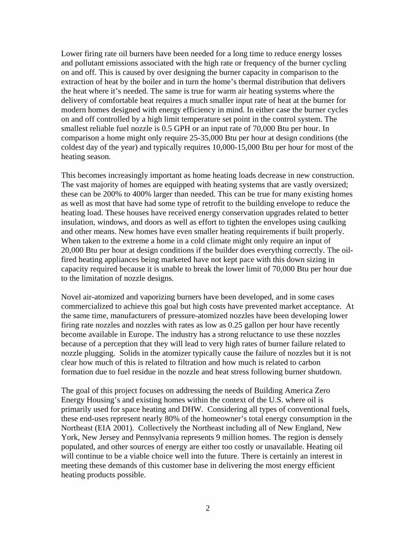
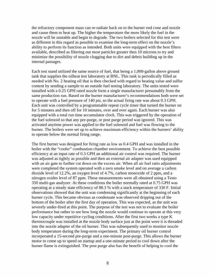
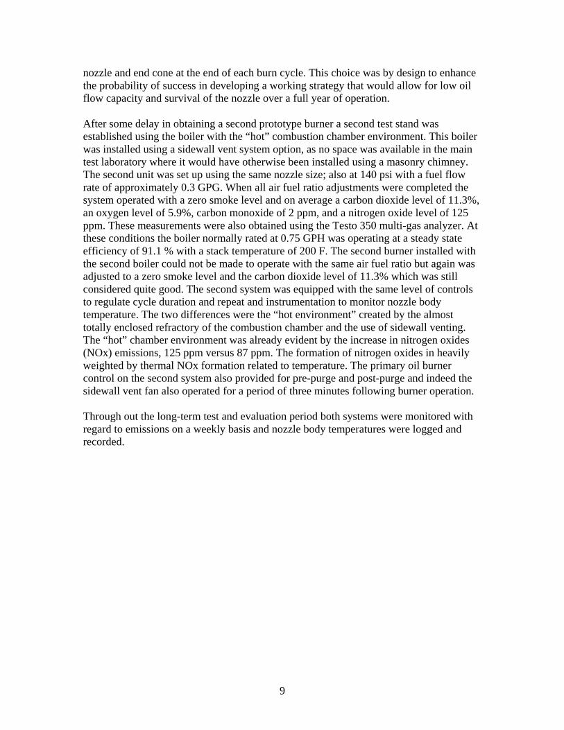
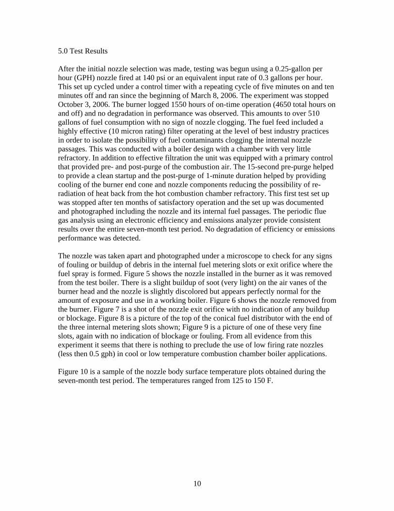
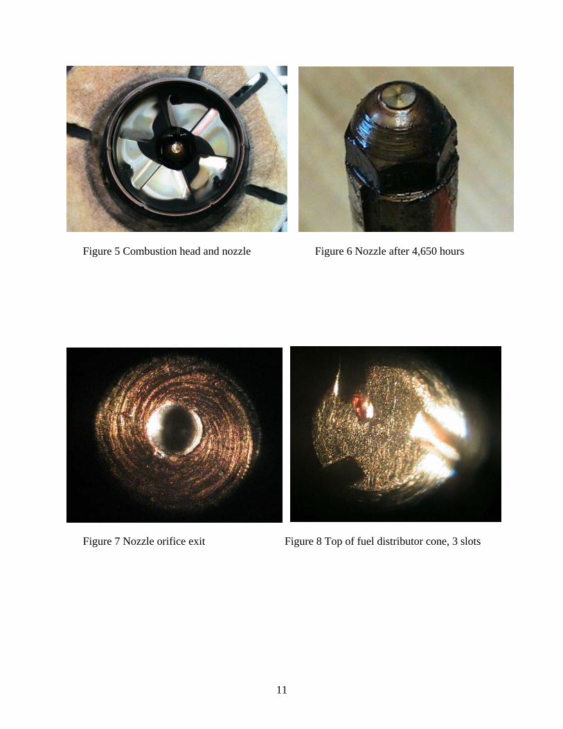
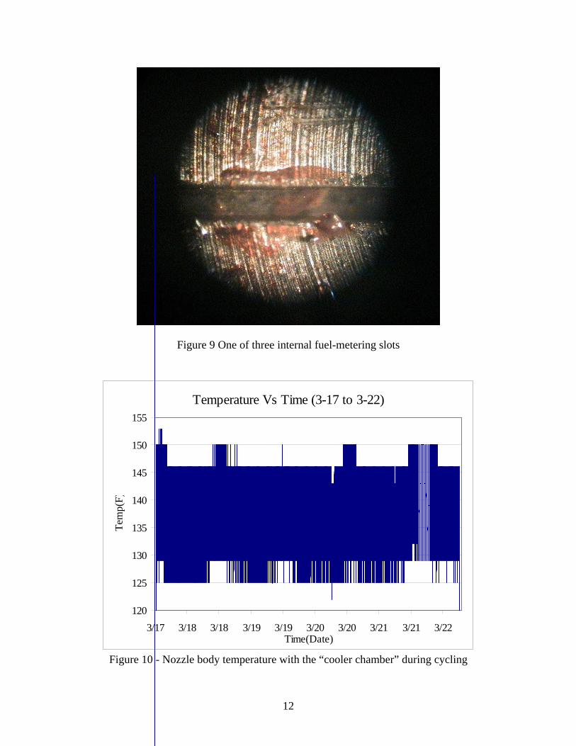
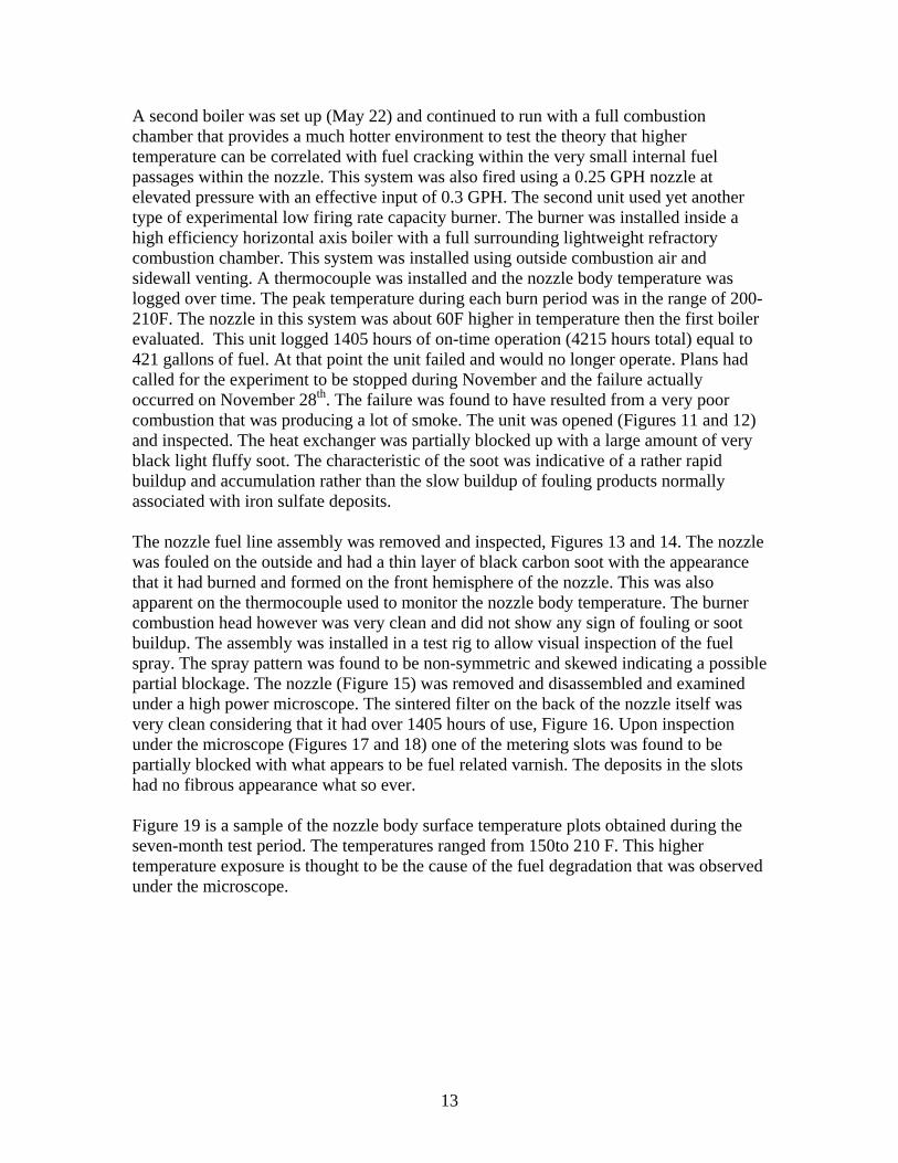
5.0 Test Results After the initial nozzle selection was made, testing was begun using a 0.25-gallon per hour (GPH) nozzle fired at 140 psi or an equivalent input rate of 0.3 gallons per hour. This set up cycled under a control timer with a repeating cycle of five minutes on and ten minutes off and ran since the beginning of March 8, 2006. The experiment was stopped October 3, 2006. The burner logged 1550 hours of on-time operation (4650 total hours on and off) and no degradation in performance was observed. This amounts to over 510 gallons of fuel consumption with no sign of nozzle clogging. The fuel feed included a highly effective (10 micron rating) filter operating at the level of best industry practices in order to isolate the possibility of fuel contaminants clogging the internal nozzle passages. This was conducted with a boiler design with a chamber with very little refractory. In addition to effective filtration the unit was equipped with a primary control that provided pre- and post-purge of the combustion air. The 15-second pre-purge helped to provide a clean startup and the post-purge of 1-minute duration helped by providing cooling of the burner end cone and nozzle components reducing the possibility of re-radiation of heat back from the hot combustion chamber refractory. This first test set up was stopped after ten months of satisfactory operation and the set up was documented and photographed including the nozzle and its internal fuel passages. The periodic flue gas analysis using an electronic efficiency and emissions analyzer provide consistent results over the entire seven-month test period. No degradation of efficiency or emissions performance was detected. The nozzle was taken apart and photographed under a microscope to check for any signs of fouling or buildup of debris in the internal fuel metering slots or exit orifice where the fuel spray is formed. Figure 5 shows the nozzle installed in the burner as it was removed from the test boiler. There is a slight buildup of soot (very light) on the air vanes of the burner head and the nozzle is slightly discolored but appears perfectly normal for the amount of exposure and use in a working boiler. Figure 6 shows the nozzle removed from the burner. Figure 7 is a shot of the nozzle exit orifice with no indication of any buildup or blockage. Figure 8 is a picture of the top of the conical fuel distributor with the end of the three internal metering slots shown; Figure 9 is a picture of one of these very fine slots, again with no indication of blockage or fouling. From all evidence from this experiment it seems that there is nothing to preclude the use of low firing rate nozzles (less then 0.5 gph) in cool or low temperature combustion chamber boiler applications. Figure 10 is a sample of the nozzle body surface temperature plots obtained during the seven-month test period. The temperatures ranged from 125 to 150 F.
11
Figure 5 Combustion head and nozzle Figure 6 Nozzle after 4,650 hours
Figure 7 Nozzle orifice exit Figure 8 Top of fuel distributor cone, 3 slots
12
Figure 9 One of three internal fuel-metering slots
Temperature Vs Time (3-17 to 3-22)
120
125
130
135
140
145
150
155
3/17 3/18 3/18 3/19 3/19 3/20 3/20 3/21 3/21 3/22Time(Date)
Tem
p(F)
Figure 10 - Nozzle body temperature with the “cooler chamber” during cycling
13
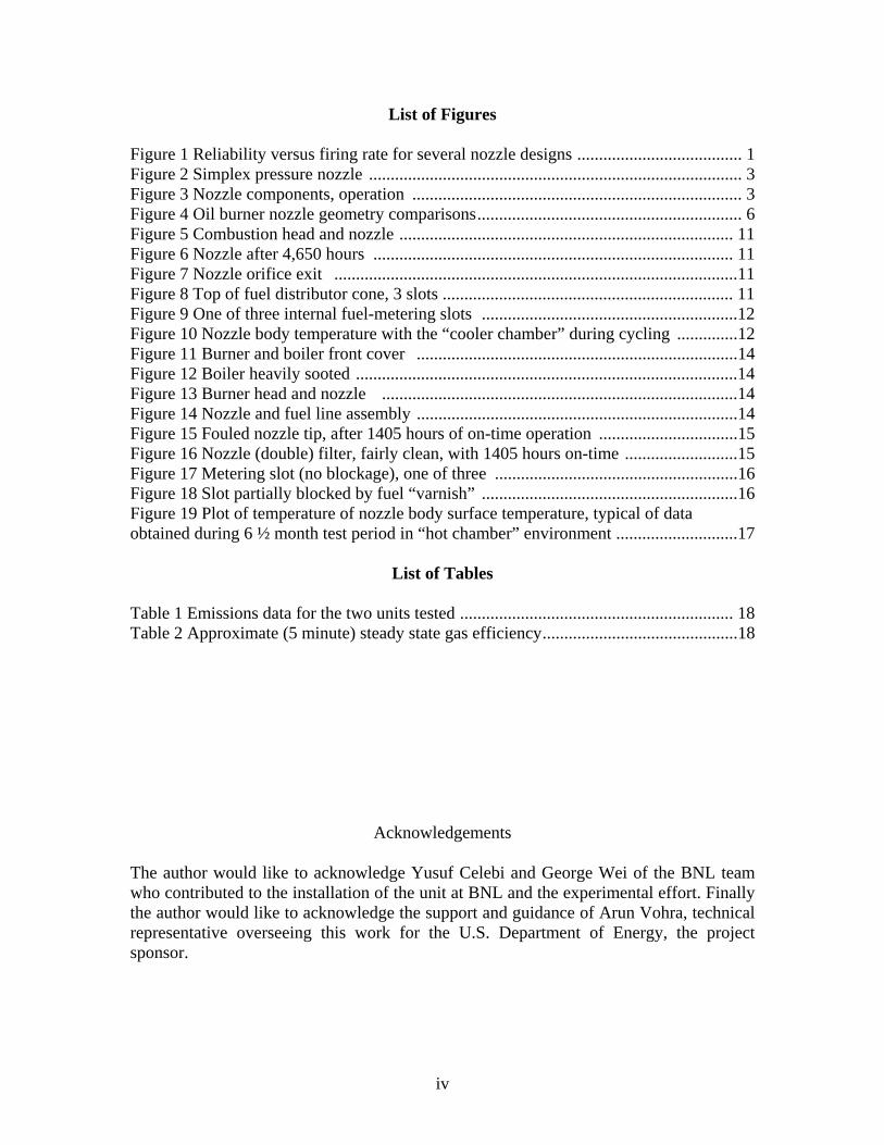
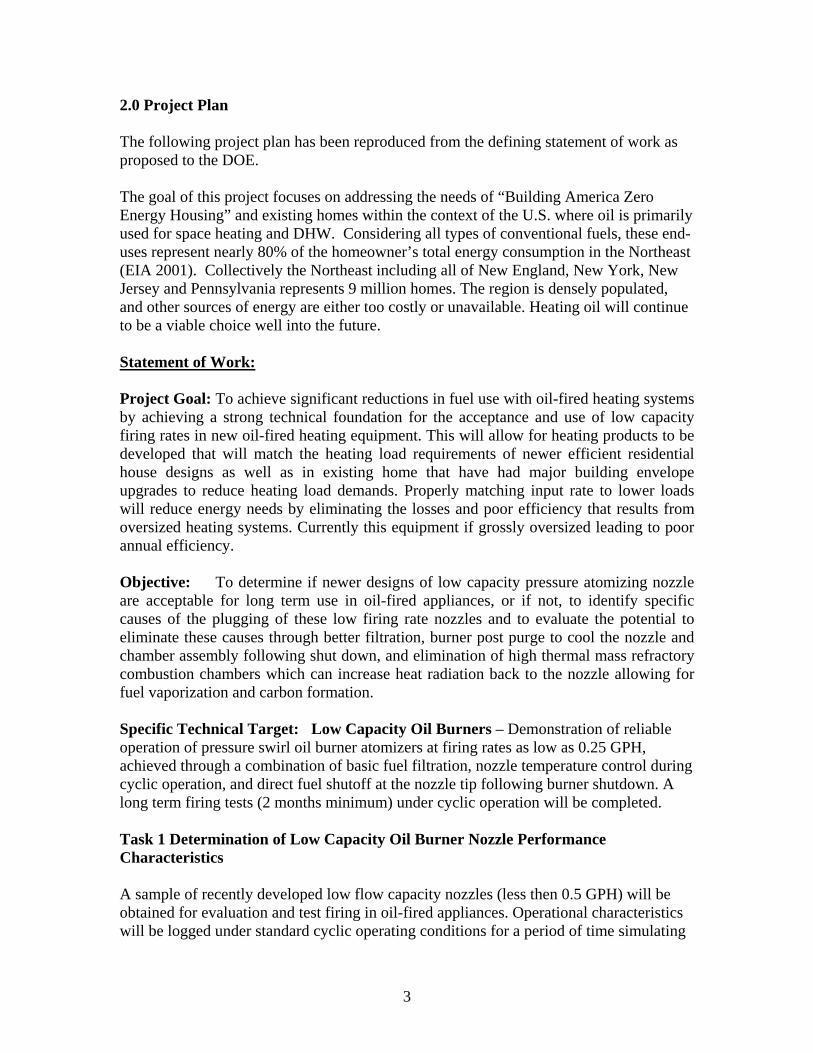
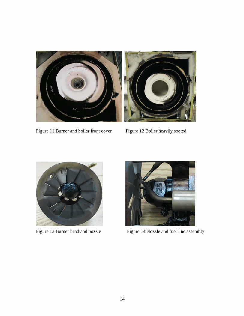
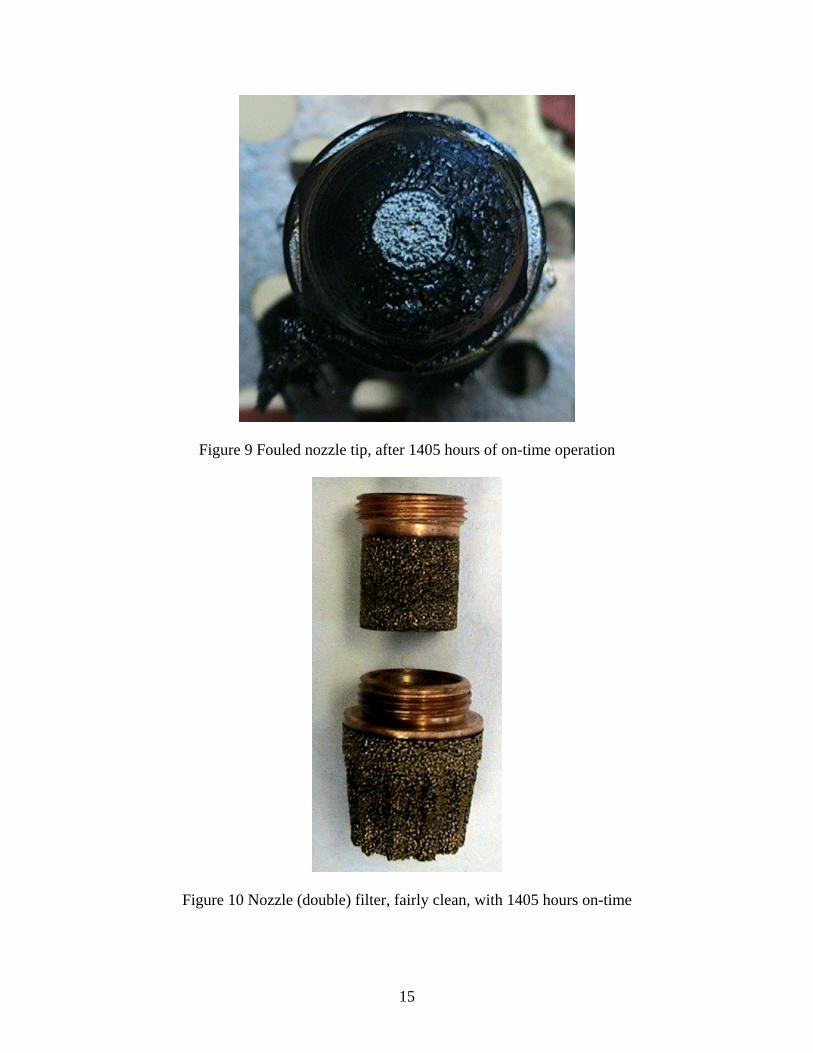
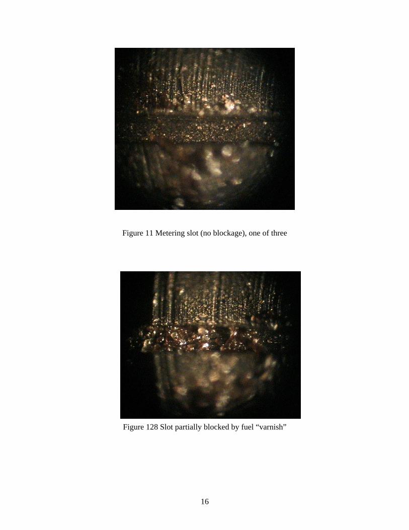
A second boiler was set up (May 22) and continued to run with a full combustion chamber that provides a much hotter environment to test the theory that higher temperature can be correlated with fuel cracking within the very small internal fuel passages within the nozzle. This system was also fired using a 0.25 GPH nozzle at elevated pressure with an effective input of 0.3 GPH. The second unit used yet another type of experimental low firing rate capacity burner. The burner was installed inside a high efficiency horizontal axis boiler with a full surrounding lightweight refractory combustion chamber. This system was installed using outside combustion air and sidewall venting. A thermocouple was installed and the nozzle body temperature was logged over time. The peak temperature during each burn period was in the range of 200-210F. The nozzle in this system was about 60F higher in temperature then the first boiler evaluated. This unit logged 1405 hours of on-time operation (4215 hours total) equal to 421 gallons of fuel. At that point the unit failed and would no longer operate. Plans had called for the experiment to be stopped during November and the failure actually occurred on November 28th. The failure was found to have resulted from a very poor combustion that was producing a lot of smoke. The unit was opened (Figures 11 and 12) and inspected. The heat exchanger was partially blocked up with a large amount of very black light fluffy soot. The characteristic of the soot was indicative of a rather rapid buildup and accumulation rather than the slow buildup of fouling products normally associated with iron sulfate deposits. The nozzle fuel line assembly was removed and inspected, Figures 13 and 14. The nozzle was fouled on the outside and had a thin layer of black carbon soot with the appearance that it had burned and formed on the front hemisphere of the nozzle. This was also apparent on the thermocouple used to monitor the nozzle body temperature. The burner combustion head however was very clean and did not show any sign of fouling or soot buildup. The assembly was installed in a test rig to allow visual inspection of the fuel spray. The spray pattern was found to be non-symmetric and skewed indicating a possible partial blockage. The nozzle (Figure 15) was removed and disassembled and examined under a high power microscope. The sintered filter on the back of the nozzle itself was very clean considering that it had over 1405 hours of use, Figure 16. Upon inspection under the microscope (Figures 17 and 18) one of the metering slots was found to be partially blocked with what appears to be fuel related varnish. The deposits in the slots had no fibrous appearance what so ever. Figure 19 is a sample of the nozzle body surface temperature plots obtained during the seven-month test period. The temperatures ranged from 150to 210 F. This higher temperature exposure is thought to be the cause of the fuel degradation that was observed under the microscope.
14
Figure 11 Burner and boiler front cover Figure 12 Boiler heavily sooted
Figure 13 Burner head and nozzle Figure 14 Nozzle and fuel line assembly
15
Figure 9 Fouled nozzle tip, after 1405 hours of on-time operation
Figure 10 Nozzle (double) filter, fairly clean, with 1405 hours on-time
16
Figure 11 Metering slot (no blockage), one of three
Figure 128 Slot partially blocked by fuel “varnish”
17
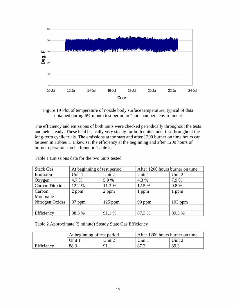
Figure 19 Plot of temperature of nozzle body surface temperature, typical of data obtained during 6½-month test period in “hot chamber” environment
The efficiency and emissions of both units were checked periodically throughout the tests and held steady. These held basically very steady for both units under test throughout the long-term cyclic trials. The emissions at the start and after 1200 burner on time hours can be seen in Tables 1. Likewise, the efficiency at the beginning and after 1200 hours of burner operation can be found in Table 2. Table 1 Emissions data for the two units tested
At beginning of test period After 1200 hours burner on time Stack Gas Emission Unit 1 Unit 2 Unit 1 Unit 2 Oxygen 4.7 % 5.9 % 4.3 % 7.9 % Carbon Dioxide 12.2 % 11.3 % 12.5 % 9.8 % Carbon Monoxide
2 ppm 2 ppm 1 ppm 1 ppm
Nitrogen Oxides 87 ppm 125 ppm 90 ppm 103 ppm Efficiency 88.3 % 91.1 % 87.3 % 89.3 % Table 2 Approximate (5 minute) Steady State Gas Efficiency
At beginning of test period After 1200 hours burner on time Unit 1 Unit 2 Unit 1 Unit 2
Efficiency 88.3 91.1 87.3 89.3
0
50
100
150
200
250
10-Jul 12-Jul 14-Jul 16-Jul 18-Jul 20-Jul 22-Jul 24-Jul
Date
Deg
. F
18
7.0 Conclusions BNL has conducted a preliminary evaluation of the potential of recently developed lines of very low fuel input capacity Simplex type pressure atomizing nozzles for use with oil burners designed for residential boilers, furnaces and water heaters. Given the limited laboratory space for establishing long term evaluations of these systems while allowing for other projects in the area of oilheat research to continue a decision was made to isolate the most probable failure mechanisms and to provide the best industry practice to avoid those issues of concern with known solutions. If a nozzle were going to fail it seems reasonable that it would very likely be due to plugging or partial plugging of the internal fuel passages, namely the very tiny fuel metering slots. These slots are on the order of 6/1000 of an inch or less in the firing range of interest. The assumption being that this failure would be either a result of a buildup of contaminants or more likely degraded fuel, creating varnish like deposits in the slots and plugging or partially plugging the fuel passages. It is suggested that the issue of fuel contamination can be resolved based on the proper use of the best modern filtration techniques already available to the oilheat industry. This is accomplished by using filters rated at 10 microns or better. The other likely failure mode is fuel degradation, which can be caused by several factors but is made significantly worse when stressed by a high temperature thermal environment. This can be avoided to a certain extent by using modern controls that provide the option of post-purge control of combustion air creating a cooler thermal condition prior to shut off by allowing a purging flow of air prior to shut down. Excessive periods of post purge do tend to reduce the efficiency by allowing stored heat to escape up the chimney. For this reason the shortest post-period of one minute was selected for this study. In the case of the sidewall vented unit (with the “hotter combustion chamber” environment) this post-purge period was followed by the continued operation of the draft inducer, for a total of three minutes. The use of a control with a pre-purge period also enhances nozzle cleanliness by helping create the opportunity for a quick crisp light off of the burner by bringing the motor, pump and air flow up to operating speed prior to opening the fuel solenoid valve. A solenoid valve is recommended regardless of pump design in providing clean starts and stops. To utilize low flow capacity nozzles they need to be kept as “cool” as possible. In the case of the first unit the surface temperature of the nozzle was kept at or below 150 F, This, coupled with the use of pre- and post purge and a high quality 10 micron filter, provided conditions that allowed for a total period of 4650 hours of operation (1550 burner on-time running hours). At the end of this period it was deemed a success and the experiment was stopped. This was for a burner on period of five minutes and off for 10 minutes with the actual input rates at 0.3 GPH using a high-pressure Simplex type nozzle rated at 0.25 GPH (@ 100 psi). In the second case the burner failed after 1405 hours of on-time operation (4215 hours total) equal to 421 gallons of fuel in fuel consumption. A this point the unit started to exhibit poor performance and a high smoke condition, followed shortly after by system shut down by the primary control’s failure to sense the flame. Upon examination the

19
failure was identified as a result a skewed atomization pattern, which led to the poor combustion and smoky conditions in the flame. This system was equipped with the same fuel filter as the first unit tested. Upon disassembly of the nozzle it was further determined that a partial blockage of one of the three-fuel distribution slots in the nozzle was the root cause. This, by visual observation, appeared to be created by a very tiny build up of “varnish” in the fuel distribution slot. There were no fibers or built up debris observed. This nozzle had been exposed to higher temperatures that had resulted in a nozzle body temperature of up to 210 F on the outer surface. This is considered to be the cause of the system failure The conclusion drawn from this study is that if low capacity nozzles are to be used they should be installed only with relatively “cool” combustion chamber designs typical of a wet base boiler with water backed walls and a minimum of refractory used to support the burning process if any is used at all. Based on this study these nozzles can be effective in these types of systems and provide a pathway to designing small efficient boilers for residential heating. Other means to keep the fuel in the nozzle cool not currently employed by oil burner manufacturers could conceivably resolve this issue by another method. This might include the use of a fuel re-circulating system loop or a finned nozzle adaptor to help remove heat from the nozzle. In addition the use of a gas re-circulation burner similar to low-NOx emissions burner used in Europe might also be an alterative route to success. These burners by design generally have a tube mounted in front of and surrounding the nozzle, which would limit the geometric view factor of any hot refractory to the nozzle eliminating most of the potential for heat re-radiation. These tubes are very hot during operation but also have very limited thermal storage capacity and by using post-purge most of the heat could be quickly dissipated.