Embed Size (px)
Citation preview
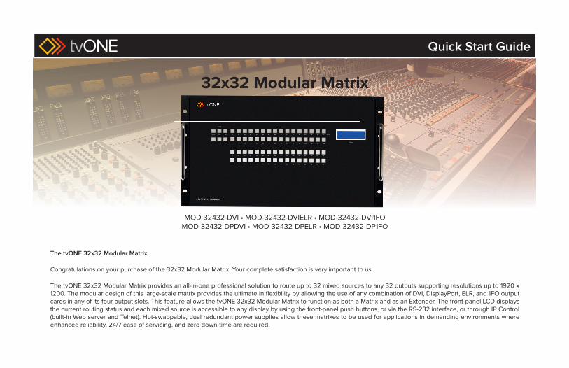
32x32 Modular Matrix
MOD-32432-DVI • MOD-32432-DVIELR • MOD-32432-DVI1FOMOD-32432-DPDVI • MOD-32432-DPELR • MOD-32432-DP1FO
The tvONE 32x32 Modular Matrix
Congratulations on your purchase of the 32x32 Modular Matrix. Your complete satisfaction is very important to us.
The tvONE 32x32 Modular Matrix provides an all-in-one professional solution to route up to 32 mixed sources to any 32 outputs supporting resolutions up to 1920 x 1200. The modular design of this large-scale matrix provides the ultimate in fl exibility by allowing the use of any combination of DVI, DisplayPort, ELR, and 1FO output cards in any of its four output slots. This feature allows the tvONE 32x32 Modular Matrix to function as both a Matrix and as an Extender. The front-panel LCD displays the current routing status and each mixed source is accessible to any display by using the front-panel push buttons, or via the RS-232 interface, or through IP Control (built-in Web server and Telnet). Hot-swappable, dual redundant power supplies allow these matrixes to be used for applications in demanding environments where enhanced reliability, 24/7 ease of servicing, and zero down-time are required.
Quick Start Guide

www.tvone.com
Before reading this Quick-Start Guide, familiarize yourself with the rear panel of the 32x32 Modular Matrix.
The 32x32 Modular Matrix can accommodate up to four output cards and four input cards. Each card provides eight connectors, providing up to 32 inputs and 32 outputs. The 32x32 Modular Matrix is sold pre-confi gured with a combination of input and output cards best suited for the needs of your application. We will cover each confi guration in the next section. First, we will identify the location of each input and output card on the matrix.
Matrix Layout (all confi guration options)
The bottom-four expansion bays of the matrix only accept input cards.The top-four expansion bays only accept output cards. Each expansion bay on the matrix is identifi ed with a letter: A, B, C, and D, from top to bottom (see opposite page).
The inputs and outputs are numbered on each card, from left-to-right.
Blue LEDs on each card indicate that the card is properly powered.
Consult the User Manual for additional information on the rear-panel layout.
1
NOTE: When a card is not installed, it is recommended that a cover plate be installed over the expansion bay to prevent dust and other foreign particles from entering the matrix.
Quick Start Guide
Make sure you have everything that came with your product:Refer to page 3 for the included items shipped with your product.
tvONE USA2791 Circleport Drive, Erlanger, KY 41018Telephone: 859-980-0420Fax: 859-282-8225Email: [email protected] us on the Web: www. tvone.comTechnical Support Hours: 8:00 AM to 5:00 PM Monday - Friday, EDT
tvONE EMEAUnit V, Continental Approach, Westwood Ind Est, Margate, Kent CT9 4JG, UKTelephone: +44 (0)1843 873322Fax: +44 (0)1843 873301Email: [email protected] us on the Web: www. tvone.comTechnical Support Hours: 8:00 AM to 5:30 PM Monday - Friday, GMTFor 24 / 7 support, see the back of the product for the support number
Refer to the last page of this Quick-Start Guide for contact information.
NOTE: For important operational details and warranty information, refer to the User Manual, which can be downloaded from the Support section of the tvONE Web site
Start Here 1IntroductionThe 32x32 ModularMX Matrix
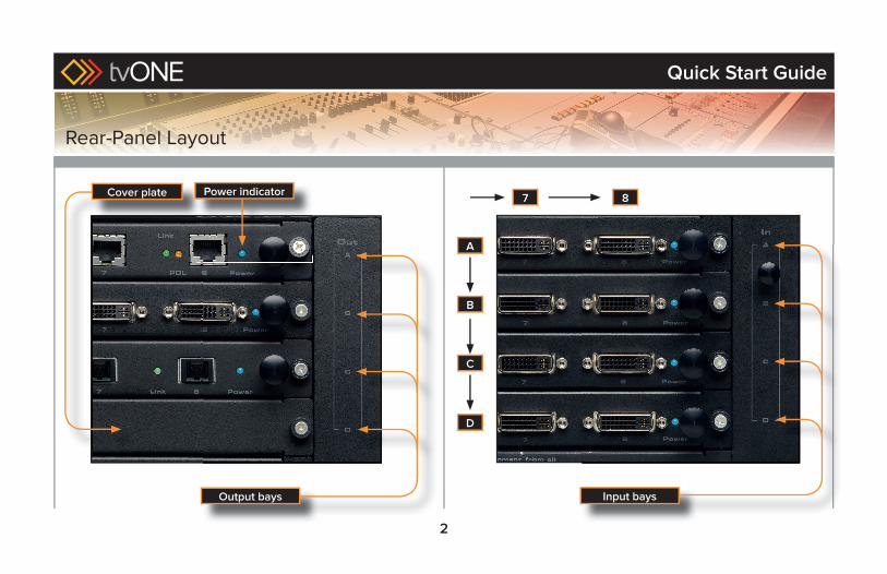
Output bays Input bays
2
Cover plate 87
A
B
C
D
Power indicator
Quick Start Guide
Rear-Panel Layout
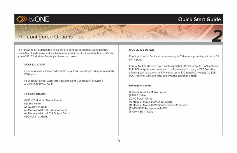
The following list outlines the available pre-confi gured options. Because this Quick-Start Guide covers all available confi gurations, it is important to identify the type of 32x32 Modular Matrix you have purchased:
• MOD-32432-DVI
Four input cards. Each card contains eight DVI inputs, providing a total of 32 DVI inputs.
Four output cards. Each card contains eight DVI outputs, providinga total of 32 DVI outputs.
Package Includes:
(1) 32x32 Modular Matrix Frame(1) DB-9 cable(2) AC power cords(4) Modular Matrix 8 DVI Input Cards(4) Modular Matrix 8 DVI Output Cards(1) Quick-Start Guide
• MOD-32432-DVIELR
Four input cards. Each card contains eight DVI inputs, providing a total of 32 DVI inputs.
Four output cards. Each card contains eight ELR-POL outputs. Each of these ELR-POL outputs are connected to a Receiver unit, using a CAT-5e cable, allowing you to extend the DVI signal up to 330 feet (100 meters). 32 ELR-POL Receiver units are included with this package option.
Package Includes:
(1) 32x32 Modular Matrix Frame(1) DB-9 Cable(2) AC Power Cords(4) Modular Matrix 8 DVI Input Cards(4) Modular Matrix 8 DVI Sender over CAT-5 Cards(32) DVI ELR Receivers with POL(1) Quick-Start Guide
3
Quick Start Guide
Pre-confi gured Options 2
4
• MOD-32432-DPELR
Four input cards. Each card contains eight DisplayPort inputs, providing a total of 32 DisplayPort inputs.
Four output cards. Each card contains eight ELR-POL outputs. Each of these ELR-POL outputs are connected to a Receiver unit, using a CAT-5e cable, allowing you to extend the DisplayPort signal up to 330 feet (100 meters). 32 ELR-POL Receiver units are included with this package option.
Package Includes:
(1) 32x32 Modular Matrix Frame(1) DB-9 Cable(2) AC Power Cords(4) Modular Matrix 8 DisplayPort Cards(4) Modular Matrix 8 DVI Sender over CAT-5 Cards(32) DVI ELR Receivers with POL(1) Quick-Start Guide
• MOD-32432-DPDVI
Four input cards. Each card contains eight DisplayPort inputs, providing a total of 32 DisplayPort inputs.
Four output cards. Each card contains eight DVI outputs, providing a total of 32 DVI outputs.
Package Includes:
(1) 32x32 Modular Matrix Frame(1) DB-9 Cable(2) AC Power Cords(4) Modular Matrix 8 DisplayPort Cards(4) Modular Matrix 8 DVI Output Cards(1) Quick-Start Guide
Quick Start Guide
Pre-confi gured Options (continued)
5
• MOD-32432-DVI1FO
Four input cards. Each card contains eight DVI inputs, providing a total of 32 DVI inputs.
Four output cards. Each card contains eight SC-type fi ber optic connectors. Each of these fi ber optic connectors are connected to a Receiver unit, allowing you to extend the DVI signal up to 6600 feet(2 kilometers) using 50μ OM3e multimode fi ber optic cable. OM3 andOM1 fi ber are also supported. See the User Manual for distance limitations using other fi ber optic cable types. 32 fi ber optic Receiver units are included with this package option.
Package Includes:
(1) 32x32 Modular Matrix Frame(1) DB-9 Cable(2) AC Power Cords(4) Modular Matrix 8 DVI Input Cards(4) Modular Matrix 8 Fiber Optic Output Cards(32) DVI Receivers over 1FO(32) 5V Power Supplies for the above(1) Quick-Start Guide
Quick Start Guide
Pre-confi gured Options (continued)
• MOD-32432-DP1FO
Four input cards. Each card contains eight DisplayPort inputs, providing a total of 32 DisplayPort inputs.
Four output cards. Each card contains eight SC-type fi ber optic connectors. Each of these fi ber optic connectors are connected to a Receiver unit, allowing you to extend the DisplayPort signal up to 6600 feet(2 kilometers) using 50μ OM3e multimode fi ber optic cable. OM3 andOM1 fi ber are also supported. See the User Manual for distance limitations using other fi ber optic cable types. 32 fi ber optic Receiver units are included with this package option.
Package Includes:
(1) 32x32 Modular Matrix Frame(1) DB-9 Cable(2) AC Power Cords(4) Modular Matrix 8 DisplayPort Input Cards(4) Modular Matrix 8 Fiber Optic Output Cards(32) DVI Receivers over 1FO(32) 5V Power Supplies for the above(1) Quick-Start Guide
If any of the items from these pre-confi gured packages are missing, call tvONE Technical Support. Refer to page 1 of this guide for contact information.
6
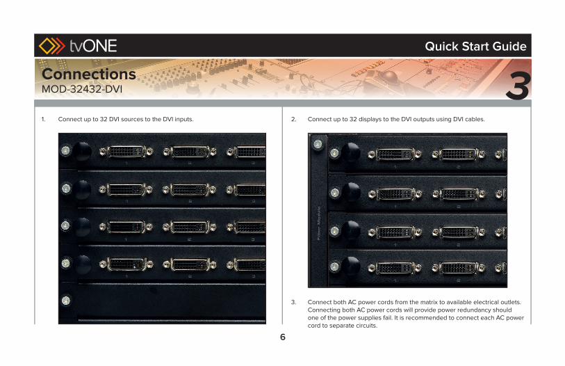
2. Connect up to 32 displays to the DVI outputs using DVI cables.
3. Connect both AC power cords from the matrix to available electrical outlets.Connecting both AC power cords will provide power redundancy should one of the power supplies fail. It is recommended to connect each AC power cord to separate circuits.
1. Connect up to 32 DVI sources to the DVI inputs.
Quick Start Guide
ConnectionsMOD-32432-DVI 3
7
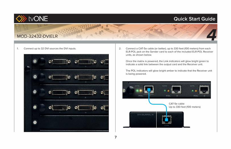
1. Connect up to 32 DVI sources the DVI inputs.
MOD-32432-DVIELR
2. Connect a CAT-5e cable (or better), up to 330 feet (100 meters) from each ELR-POL jack on the Sender card to each of the included ELR-POL Receiver units, as shown below.
Once the matrix is powered, the Link indicators will glow bright green to indicate a solid link between the output card and the Receiver unit.
The POL indicators will glow bright amber to indicate that the Receiver unit is being powered.
CAT-5e cableUp to 330 feet (100 meters)
Quick Start Guide
4
8
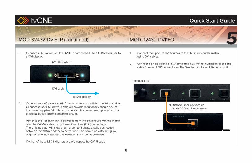
3. Connect a DVI cable from the DVI Out port on the ELR-POL Receiver unit to a DVI display.
4. Connect both AC power cords from the matrix to available electrical outlets.Connecting both AC power cords will provide redundancy should one of the power supplies fail. It is recommended to connect each power cord to electrical outlets on two separate circuits.
Power to the Receiver unit is delivered from the power supply in the matrix over the CAT-5e cable using Power Over Line (POL) technology. The Link indicator will glow bright green to indicate a solid connection between the matrix and the Receiver unit. The Power indicator will glow bright blue to indicate that the Receiver unit is being powered.
If either of these LED indicators are off , inspect the CAT-5 cable.
DVI cable
to DVI display
DVI-ELRPOL-R
MOD-32432-DVIELR (continued)
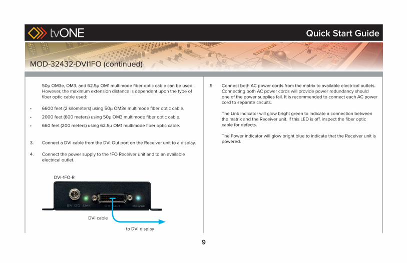
1. Connect the up to 32 DVI sources to the DVI inputs on the matrixusing DVI cables.
2. Connect a single strand of SC-terminated 50μ OM3e multimode fi ber optic cable from each SC connector on the Sender card to each Receiver unit.
MOD-32432-DVI1FO
Multimode Fiber Optic cableUp to 6600 feet (2 kilometers)
DVI-1FO-R
MOD-8FO-S
Quick Start Guide
5
9
50μ OM3e, OM3, and 62.5μ OM1 multimode fi ber optic cable can be used. However, the maximum extension distance is dependent upon the type of fi ber optic cable used:
• 6600 feet (2 kilometers) using 50μ OM3e multimode fi ber optic cable.
• 2000 feet (600 meters) using 50μ OM3 multimode fi ber optic cable.
• 660 feet (200 meters) using 62.5μ OM1 multimode fi ber optic cable.
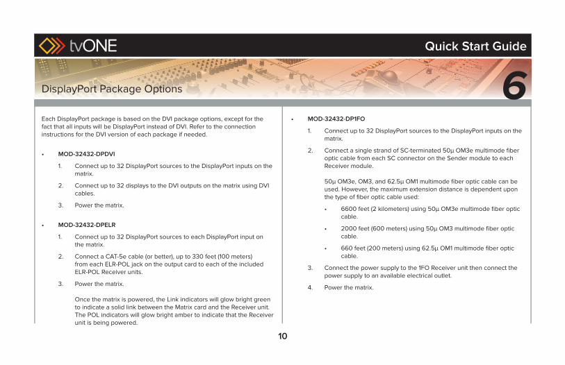
3. Connect a DVI cable from the DVI Out port on the Receiver unit to a display.
4. Connect the power supply to the 1FO Receiver unit and to an available electrical outlet.
MOD-32432-DVI1FO (continued)
5. Connect both AC power cords from the matrix to available electrical outlets. Connecting both AC power cords will provide power redundancy should one of the power supplies fail. It is recommended to connect each AC power cord to separate circuits.
The Link indicator will glow bright green to indicate a connection between the matrix and the Receiver unit. If this LED is off , inspect the fi ber optic cable for defects.
The Power indicator will glow bright blue to indicate that the Receiver unit is powered.
DVI cable
to DVI display
DVI-1FO-R
Quick Start Guide
10
DisplayPort Package Options 6Each DisplayPort package is based on the DVI package options, except for the fact that all inputs will be DisplayPort instead of DVI. Refer to the connection instructions for the DVI version of each package if needed.
• MOD-32432-DPDVI
1. Connect up to 32 DisplayPort sources to the DisplayPort inputs on the matrix.
2. Connect up to 32 displays to the DVI outputs on the matrix using DVI cables.
3. Power the matrix.
• MOD-32432-DPELR
1. Connect up to 32 DisplayPort sources to each DisplayPort input on the matrix.
2. Connect a CAT-5e cable (or better), up to 330 feet (100 meters)from each ELR-POL jack on the output card to each of the included ELR-POL Receiver units.
3. Power the matrix.
Once the matrix is powered, the Link indicators will glow bright green to indicate a solid link between the Matrix card and the Receiver unit.The POL indicators will glow bright amber to indicate that the Receiver unit is being powered.
• MOD-32432-DP1FO
1. Connect up to 32 DisplayPort sources to the DisplayPort inputs on the matrix.
2. Connect a single strand of SC-terminated 50μ OM3e multimode fi ber optic cable from each SC connector on the Sender module to each Receiver module.
50μ OM3e, OM3, and 62.5μ OM1 multimode fi ber optic cable can be used. However, the maximum extension distance is dependent upon the type of fi ber optic cable used:
• 6600 feet (2 kilometers) using 50μ OM3e multimode fi ber optic cable.
• 2000 feet (600 meters) using 50μ OM3 multimode fi ber optic cable.
• 660 feet (200 meters) using 62.5μ OM1 multimode fi ber optic cable.
3. Connect the power supply to the 1FO Receiver unit then connect the power supply to an available electrical outlet.
4. Power the matrix.
Quick Start Guide
11
Although each 32x32 Modular Matrix is sold pre-confi gured, both input and output cards can be removed or added to fi t the needs of the application.
Each card can easily be removed and installed without using any special tools.
1. Power OFF the matrix.
2. Turn the matrix around so the back of the unit is facing you.
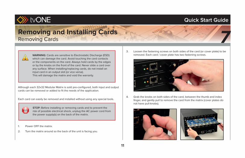
3. Loosen the fastening screws on both sides of the card (or cover plate) to be removed. Each card / cover plate has two fastening screws.
4. Grab the knobs on both sides of the card, between the thumb and index fi nger, and gently pull to remove the card from the matrix (cover plates do not have pull-knobs).
7WARNING: Cards are sensitive to Electrostatic Discharge (ESD) which can damage the card. Avoid touching the card contacts or the components on the card. Always hold cards by the edges or by the knobs on the front of the card. Never slide a card over any surface. When installing/replacing cards, do not install an input card in an output slot (or vice versa).This will damage the matrix and void the warranty.
STOP: Before installing or removing cards and to prevent the risk of possible electrical shock, unplug the AC power cord from the power supply(s) on the back of the matrix.
Removing and Installing CardsRemoving Cards
Quick Start Guide
12
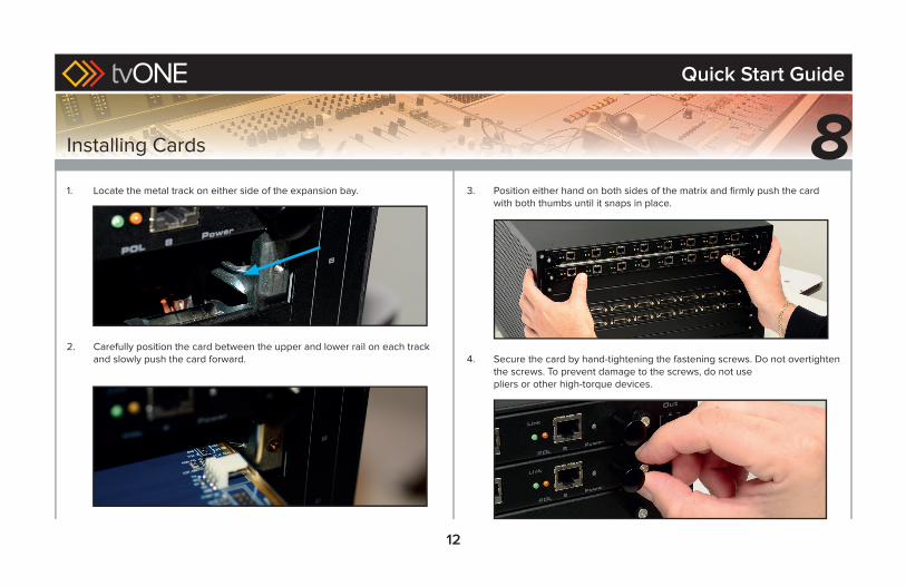
Installing Cards
1. Locate the metal track on either side of the expansion bay.
2. Carefully position the card between the upper and lower rail on each track and slowly push the card forward.
3. Position either hand on both sides of the matrix and fi rmly push the card with both thumbs until it snaps in place.
4. Secure the card by hand-tightening the fastening screws. Do not overtighten the screws. To prevent damage to the screws, do not usepliers or other high-torque devices.
8Quick Start Guide

www.tvone.com

32x32 ModularMX is a trademark of tvONE
tvONE reserves the right to make changes in the hardware, packaging, and any accompanying documentation without prior written notice.© 2014 tvONE. All rights reserved.
All trademarks are the property of their respective owners.Features and specifications are subject to change without notice.
PbThis product uses UL listed or CE compliant power supplies.
tvONE USA2791 Circleport Drive, Erlanger, KY 41018 USA
800-721-4044 fax: 859-282-8225
tvONE EMEAContinental Approach, Westwood Ind. Est., Margate, Kent CT9 4JG UK
+44 (0)1843 873311 fax: +44 (0)1843 873312
www. tvone.com