Embed Size (px)
Citation preview

FR6802+Frames
Installation and Operation Manual
Edition C175-000151-00

Experience an Integrated Content Environment Leitch Technology is uniquely capable of meeting the needs of customers with a full range of products that providethe experience of an Integrated Content Environment — a streamlined workflow for the production, processing,transmission and management of content.
The area of content production has seen increases in source and output formats, effects, layers and volume ofmaterial to be edited. As a result, editors need tools that enable increased productivity to offset these additionaltime demands, while increasing performance and enhancing creativity.
VelocityQ™ running on Quattrus™ hardware, including a new interface style featuring the unique EyeCon View, hasreceived glowing reviews for its “real-time full-quality” playback speed of four video streams, up to six graphiclayers and four 3D DVEs.
Leitch’s new NEXIO™ server system, a modular, scalable and highly cost-effective storage infrastructure for newsand transmission environments, includes gigabit Ethernet for easy integration with IP networks for movement ofcontent. NEXIO features industry-leading productivity — with the introduction of Ingest Control Manager™,NewsFlash™ server-based NLE, and BrowseCutter™ II low-resolution editing system — to provide the fastest andmost effective workflow today.
The advent of fully Integrated Content Environments has led to significant efficiency improvements in workflow,with processing and monitoring now integrated and transparent.
NEO™, Leitch’s advanced processing platform, not only hosts single-function modules, but also consolidates multiplefunctions on a single “Simplicity” card. New award-winning modules have been added with the NEO VR™ digitalvideo recorder, LogoMotion™ II branding tool and the NEO SuiteView multi-source display processor. Morefunctionality can be achieved by customers’ infrastructure environments with the high-density 6800+™.
Leitch’s industry-leading routing offerings allow customers to connect high-quality signals of all formats fromanalog to HD. Panacea™ provides affordable, compact, modular routing in sizes up to 32x32. The new widebandIntegrator® Gold provides scalable routing of almost any digital signal up to 128x128 in a single frame. Allprocessing and routing platforms are fully integrated with Leitch’s advanced Command Control System (CCS™).
Advancements in digital technologies have enabled more channels, in different content formats, over multipledistribution systems. Customers now seek to achieve their vision of a fully Integrated Content Environment to supplymultiple distribution channels with high-quality content and branding.
Leitch’s NEXIO transmission server, which supports multiple compression formats in both standard and high-definition resolution, will also support ASI interface and has the ability to record, process and playback MPEG transport streams.
Leitch’s Opus™ master control switcher offers an array of effects and has the ability to control up to 16 on-air channels. Opus meets multi-channel digital integration challenges for both high-definition andstandard-definition formats.
Integrated Content Environments offer the greatest opportunity for productivity and performance gains whenemploying content management and control applications that place content, operations or remote locations undercommon software controls.
A major workflow enhancement is Leitch’s Ingest Control Manager™, which places control of up to 16 serverchannels with associated proc amps (DPS-575), eight VTRs and eight separate routers under one control station.
Leitch’s CCS Navigator™, winner of NAB 2003’s highest awards for control and monitoring of content quality, and the CCS™ soft real-time system provide open access through standard protocols to components of a networked system.
Integrated ContentEnvironment

Edition CFebruary 2005
FR6802+Frames
Installation and Operation Manual


FR6802+ Installation and Operation Manual iii
Preface
Manual InformationPurpose
This manual details the features, installation procedures, operational procedures, and specifications of the FR6802+ Frames.
AudienceThis manual is written for engineers, technicians and operators responsible for the installation, setup, and/or operation of FR6802+ Frames.
Revision History
Table P-1. Revision History
Edition Date Revision HistoryA May 2003 Initial release
B January 2005 Addition of 6802+PS DC information as well as minor corrections to content
C February 2005 Addition of index and module card-edge navigation information

iv FR6802+ Installation and Operation Manual
Preface
Writing ConventionsTo enhance your understanding, the authors of this manual have adhered to the following text conventions:
Obtaining Leitch DocumentsLeitch documents can be viewed or downloaded from the Leitch Web site at www.leitch.com (go to Support>Documentation). Alternatively, contact your Leitch customer service representative to request a document.
Table P-2. Manual Writing Conventions
Term or Convention DescriptionBold Indicates dialog boxes, property sheets,
fields, buttons, check boxes, list boxes, combo boxes, menus, submenus, windows, lists, and selection names.
Italics Indicates email addresses, the names of books or publications, and the first instances of new terms and specialized words that need emphasis.
CAPS Indicates a specific key on the keyboard, such as ENTER, TAB, CTRL, ALT, or DELETE.
Code Indicates variables or command-line entries, such as a DOS entry or something you type into a field.
> Indicates the direction of navigation through a hierarchy of menus and windows.
hyperlink Indicates a jump to another location within the electronic document or elsewhere
Internet address Indicates a jump to a Web site or URL
NoteIndicates important information that helps to avoid and troubleshoot problems.

FR6802+ Installation and Operation Manual v
Preface
Unpacking/Shipping InformationLeitch has carefully inspected, tested, and calibrated this product before shipment to ensure years of stable and trouble free service. 1. Check equipment for any visible damage that may have occurred
during transit. 2. Confirm that you have received all items listed on the packing list. 3. Contact your Leitch dealer if any item on the packing list is
missing.4. Contact the carrier if any item is damaged.5. Remove all packaging material from the product and its associated
components before you install the unit.
Keep at least one set of original Leitch packaging, in the event that you need to return a product for servicing. If the original packaging is not available, you can purchase replacement packaging from Leitch at a modest cost or supply your own packaging as long as it meets the following criteria:• Withstands the weight of the product• Holds the product rigid within the packaging• Leaves at least 2 in. (50.8 mm) of space between the product and
the container• Protects the corners of the product
Ship products back to Leitch for servicing prepaid and, if possible, in the original packaging material. If the product is still within the warranty period, Leitch will return the product prepaid after servicing.

vi FR6802+ Installation and Operation Manual
Preface
Safety Standards and CompliancesSee the 6800+ Safety Instructions and Standards Manual to find the safety standards and compliances for this 6800+ series product. A safety manual is shipped with every FR6802+ Frames Installation and Operation Manual and can be downloaded from the Leitch Web site at www.leitch.com. Alternatively, contact your Leitch customer service representative for a copy of this safety manual.
Safety Terms and SymbolsThis product manual uses the following safety terms and symbols to identify certain conditions or practices. See the 6800+ Safety Instructions and Standards Manual for more information.
WARNING: Identifies conditions or practices that can result in personal injury or loss of life—high voltage is present. Uninsulated dangerous voltage within the product’s enclosure may be sufficient to constitute a risk of electric shock to persons.
CAUTION: Identifies conditions or practices that can result in damage to the equipment or other property. Important operating and maintenance (servicing) instructions are included in the literature accompanying the product.

FR6802+ Installation and Operation Manual vii
Contents
PrefaceManual Information ............................................................................... iii
Purpose ........................................................................................... iiiAudience ......................................................................................... iiiRevision History ............................................................................. iiiWriting Conventions ........................................................................ivObtaining Leitch Documents ...........................................................iv
Unpacking/Shipping Information ............................................................vSafety Standards and Compliances .........................................................vi
Safety Terms and Symbols ..............................................................vi
Chapter 1: IntroductionOverview ..................................................................................................1Product Description .................................................................................2
6800+ Products .................................................................................2FR6802+ Frames ..............................................................................26800 and 6800+ Co-Existence .........................................................3Available Frame Configurations and Back Panel Types ..................3
Main Features ..........................................................................................4Signal Flow ..............................................................................................5Front Panel Description ...........................................................................6Rear Panel Description ............................................................................7Fan Assembly Description .......................................................................8Power Supply Description .......................................................................9Resource Card Description ....................................................................10Communications and Control ................................................................11
Serial Control ..................................................................................11

viii FR6802+ Installation and Operation Manual
Contents
Ethernet Control ............................................................................. 12
Chapter 2: Installation and OperationOverview ............................................................................................... 13Maximum 6800+ Frame Power Ratings ............................................... 14Checking the Packing List ..................................................................... 15Meeting Location Requirements ........................................................... 16
Ensuring Proper Temperature and Ventilation ............................... 16Meeting Electrical Requirements ................................................... 16
Installing the Frame in a Rack ............................................................... 18Ensuring Adequate Rack Space ..................................................... 18Attaching Optional Rear-Support Brackets .................................... 18
Installing 6800+ Modules ..................................................................... 21Installing 6800+ Modules in an FR6802+ Series Frame ............... 22Installing 6800+ Modules into a 6800/7000 Series Frame ............ 25
Making Connections .............................................................................. 26Removing 6800+ Modules .................................................................... 26Installing Fans ....................................................................................... 27
Upgrading to an FR6800+F Frame ................................................ 27Replacing a Failed Fan Unit ........................................................... 29
Making System Connections ................................................................. 32Connecting to a Power Source ....................................................... 32Making Genlock Connections for Signal Synchronization ............ 33Creating a Serial Communication Network ................................... 34Connecting the GPI Alarm Relay to a Monitoring System ............ 36Connecting to a CCS Network ....................................................... 36
Operating the Frame .............................................................................. 37Reviewing the Steps ....................................................................... 37Understanding Status LEDs ........................................................... 38
Understanding Card-Edge Controls ...................................................... 39Introducing Control Types ............................................................. 39Introducing Parameter Types ......................................................... 40
Operating Installed Modules ................................................................. 42Operating Notes .............................................................................. 42
Chapter 3: 6802+PS and 6802+PS48 Power SuppliesOverview ............................................................................................... 43Installing a Power Supply ...................................................................... 44

FR6802+ Installation and Operation Manual ix
Contents
Disconnecting and Removing an Existing Power Supply ..............44Installing a New Power Supply ......................................................45
Protecting the Power Supply ..................................................................45Understanding Alarm Signals and Indicators ........................................46
Chapter 4: SpecificationsOverview ................................................................................................47Frame Specifications ..............................................................................48Power Supply Specifications .................................................................48
6802+PS ..........................................................................................486802+PS48 ......................................................................................50
Appendix A: Servicing InstructionsOverview ................................................................................................53Battery Use Caution ...............................................................................54Fuse Replacement Caution ....................................................................55Replacing a Resource Card ....................................................................56
Removing an Existing Resource Card ............................................56Installing a New Resource Card .....................................................56
IndexKeywords ...............................................................................................57

x FR6802+ Installation and Operation Manual
Contents

FR6802+ Installation and Operation Manual 1
Chapter 1
Introduction
OverviewThe FR6802+ Frames Installation and Operation manual describes the FR6802+ series of frames, outlines their specifications, and details the procedures for installation, configuration, and operation.This chapter introduces the FR6802+ 2RU series of frames, and briefly describes their main features. The following topics are found in this chapter:• “Product Description” on page 2• “Main Features” on page 4• “Signal Flow” on page 5• “Front Panel Description” on page 6• “Rear Panel Description” on page 7• “Fan Assembly Description” on page 8• “Power Supply Description” on page 9• “Resource Card Description” on page 10• “Communications and Control” on page 11

2 FR6802+ Installation and Operation Manual
Chapter 1: Introduction
Product Description6800+ Products
Reliable, dependable, and easy to use, 6800+ products combine high performance and exceptional quality with adaptable, cost-effective solutions.6800+ is an extension of features, an expansion of use, and an increase of performance to the solid operation you have come to know and trust in the 6800 name. Leitch invented the modular-platform; now we have again redefined the industry with an offering that resets the standard.• 6800+ Capacity: Up to 20 modules• 6800+ Compatibility: HD, SD, Analog (audio/video), Fiber Optics• 6800+ Continuity: Housing all existing 6800 products• 6800+ Control: Providing free serial and optional Ethernet control
It is everything you value about 6800...plus more.
FR6802+ FramesThe 2RU FR6802+ frames accommodate the entire 6800 line of analog/digital, audio/video products for conversion, distribution, interface, generation, and router applications. In addition, the FR6802+ frames expand the product offerings to include virtually any application in the modular arena. All interface mechanics are supported.The new FR6802+ frames provide central genlock distribution, GPI for alarms, two types of remote control interfaces, 20-slot capacity and support for multi-standard products (including HD, SD, analog, and fiber optics), and high power operation. Addressing space considerations, it sets no cooling limits on multiple frames stacked together, and is specifically designed to weigh noticeably less than other products. Each feature has been carefully designed to ensure a product that is reliable, dependable and easy-to-use.All FR6802+ frames come with absolutely free serial control. An optional interface to Ethernet is also available, allowing connectivity with all other Leitch CCS-controlled products.

FR6802+ Installation and Operation Manual 3
Chapter 1: Introduction
6800 and 6800+ Co-ExistenceFR6802+ frames are designed to house and power both 6800 and the 6800+ modules. Although the 6800+ modules have different features and controls, both work in harmony with each other in the evolved FR6802+ frames. Likewise, 6800+ modules that use the 6800-style connector interface (with 9 BNCs) can be directly used in existing 6800 frames.
Available Frame Configurations and Back Panel TypesThere are several FR6802+ frame products and packages available. For example, depending on your frame configuration and product needs, you can order an empty back panel to accommodate an assortment of individual back connectors or a solid (full) back panel to accommodate either 10 double-width or 20 single-width modules. Some members of the FR6802+ family include the following:
NoteCCS software applications and control panels will not recognize 6800+ modules when they are installed in existing 6800 frames
Table 1-1. FR6802+ Frames and Accessories
Product Code DescriptionFR6802+X 2RU frame; includes blank back connectors and one
6802+PS AC power supply
FR6802+X48 Same as above, except includes one DC power supply unit (PSU)
FR6802+XF 2RU frame; includes blank back connectors, one 6802+PS AC power supply and fan assembly
FR6802+XF48 Same as above, except includes one DC power supply
FR6802+DM 2RU frame; includes a full double-slot back panel with 10 back connectors (100 BNC metal connectors) and one 6802+PS AC power supply
FR6802+DM48 Same as above, except includes one DC power supply
FR6802+DMF Same as FR6802+DM, except includes fan assembly
FR6802+DMF48 Same as FR6802+DM48, except includes fan assembly
6802+FA Fan assembly for 2RU frame
6802+PS Redundant, single 6800+ AC power supply
6802+PS48 Redundant, single 6800+ DC power supply

4 FR6802+ Installation and Operation Manual
Chapter 1: Introduction
Main FeaturesFR6802+ frames have the following main features:General Frame• Works with most 6800 modules (using a “6800-style” rear module)
and with 6800+ modules• Configurable to a wide variety of multi-standard audio and video
conversion, routing, generation, and distribution module combinations (HD, SDI, audio, fiber optics)
• Provides space for 10 double-slot modules, 20 single-slot modules, or a combination of both double- and single-slot modules
• Provides looping reference input for video genlock, with buffered reference distribution to all modules
Thermal/Fan• Provides refined fan-cooling for a <120 W load for AC power
supply, or <105 W load for DC power supply• Cools modules using a front-to-back airflow with alarm-monitored,
low-noise fans
Control and Monitoring• Provides an RS-232 serial connection for basic control and
monitoring• Provides access to the Ethernet for more robust control and
monitoring using an optional interface module (ICE6800+)• Regulates and reports major frame operation and performance data
to the control system via a resource card
Power Supply• Houses two power supplies for full redundancy and load-sharing • Displays power and fault indicators on front panel• Includes captivated power cord(s) for AC power supplies to prevent
accidental unplugging (note: cords are not provided for the DC power supply configurations)
• Provides choice of 6802+PS for AC power or 6802+PS48 for DC power; frame can house two of either power supply or one of each

FR6802+ Installation and Operation Manual 5
Chapter 1: Introduction
Signal FlowFigure 1-1 illustrates the signal flow of FR6802+ frames:
Figure 1-1. Signal Flow Diagram
6800+ controlnetwork
Alarm GPIrelay
Genlockvideo
Alarm
+6.8V
Mainsinlet 2 Power
supply
CPUcore
Mid
plan
ePC
B
Alarmlogic
SlotIDs
Frame ID
FrameIDs
Powersupply
Buffered genlock video
LCN
232 /422
Fanpower
LEDdrives
Status
Communication
Control
Ground-6.8V
Genlockloopthru
Mainsinlet 1
D-9 serialconnector
Front door
+6.8VPSU1 fail
Gnd
+6.8V
PSU2 fail
Gnd
-6.8V
-6.8V

6 FR6802+ Installation and Operation Manual
Chapter 1: Introduction
Front Panel DescriptionFigure 1-2 shows the front view of a FR6802+ frame, and identifies the location of status LEDs, cooling fans, and front panel release screws. Figure 1-3 shows the inside of the frame with the front panel removed.
Figure 1-2. FR6802+Frame Front Panel
Figure 1-3. FR6802+ Frame with Front Panel Removed
Cooling fans (optional)(built into front panel)
Finger-release screws
Status LEDs
Rear support bracket(one of two)
Cooling Failure/Alarm/Power
Redundant power supplies
Front mounting ear
20 single-slot 6800/6800+ card guides(floor and roof)
Front mounting ear

FR6802+ Installation and Operation Manual 7
Chapter 1: Introduction
Rear Panel DescriptionFigure 1-4 identifies the location of FR6802+ rear panel components. Table 1-2 briefly describes each of the connectors and switches found on the rear panel. See “Making System Connections” on page 32 for more information on system connections.
Figure 1-4. FR6802+ Frame Rear Panel
Power mains inlets(one for each redundant PSU)
Genlock loop through BNCs
DB-9 RS-232 connector
Communication loop through BNCs
GPI connector
Frame ID rocker switches
Rear module connectors
Table 1-2. Rear Panel Components
Item DescriptionPower mains inlets Independent power source connections
GPI connector Alarm relay connection between an FR6802+ frame and a third-party control monitoring system
Frame ID rocker switches Unique frame identification switch (four possible frame ID combinations)
Communication loop through BNCs (COM LOOP)
Communication network input/output serial connections for chained frames
DB-9 RS-232 connector Serial communication link between a PC and an FR6802+ frame
Genlock loop through BNCs Video synchronization connections

8 FR6802+ Installation and Operation Manual
Chapter 1: Introduction
Fan Assembly DescriptionAn optional fan assembly is located in the front panel of an FR6802+ frame (see Figure 1-5). The fan assembly draws in air from the front of the unit, and expels it through the back.
Figure 1-5. Fan Assembly (Back View of Front Panel)
All fans are equipped with RPM monitoring circuitry. The FR6802+ resource card decodes and monitors these signal to determine fan health. Local and remote alarms report undesirable conditions that may arise.Features of the FR6802+ fan assembly include the following:• Low fan-noise emissions• Alarm RPM monitoring and recording• Alarm bus reporting of fan failure• Automatic fan shut-down when front panel is removed
FR6802+ frames can be ordered without a fan assembly for low-power applications (maximum 50 W). If you have a frame configuration that consumes over 50 W, you will need a fan assembly to prevent overheating and ensure proper system operation.

FR6802+ Installation and Operation Manual 9
Chapter 1: Introduction
Power Supply DescriptionEach FR6802+ frame can house two redundant, modular, and fully self-contained power supply units (PSU). All FR6802+ frames come with one AC or DC power supply, which can support an entire frame load. An optional redundant AC or DC power supply can be ordered separately. Power supply configurations can be a mix of AC and DC units.Each PSU is hot-swappable, ensuring no disruption to frame operation. Other features of both power supplies include the following: • Allows frame monitoring of PSU• Includes power switch on front of PSU unit • Maintains compatible output rails ±6.8 V for 6800 and 6800+
productsThe 6802+PS auto-switches 90 to 240 V AC, at 47 to 63 Hz. “Power” and “Fault” indicators are located on the front of the PSU.The 6802+PS48 supports a -48 VDC input and provides DC PSU protections including input fuse, inrush current limiting, input transient protection, short circuit protection on all outputs, and reverse input voltage protection. It provides a Power Good green LED and an Overheat red LED.
See Figure 1-3 on page 6 to locate the PSU units in the FR6802+ frame, or “Chapter 3: 6802+PS and 6802+PS48 Power Supplies” for a more detailed description.

10 FR6802+ Installation and Operation Manual
Chapter 1: Introduction
Resource Card DescriptionThe resource card installed in every FR6802+ frame regulates and reports major frame operation, functionality, and status particulars to the control system. The resource card acts as an interface to the control system and provides interconnectivity to logical and coaxial control networks. Monitoring responsibilities include the following:• Fan health monitoring• Alarm state reporting for status bus and front-panel closure• Monitoring and reporting of frame status particulars to the control
system
See “Appendix A: Servicing Instructions” for information on locating, removing, and installing resource cards.

FR6802+ Installation and Operation Manual 11
Chapter 1: Introduction
Communications and ControlFR6802+ frames have two methods for communication and control: serial (standard), and Ethernet (optional).
Serial ControlBy creating a serial connection between FR6802+ frames and a PC running the +Pilot Lite software application, you can monitor and control every frame and its installed devices from the PC. Using BNC coaxial cables, you can connect up to four FR6802+ frames to create a network where input and output signals are shared. Then, using an RS-232 null modem serial cable connection, connect one of the frames to the PC. This communication and control method is a standard feature on all FR6802+ frames. See “Creating a Serial Communication Network” on page 34 for more detailed instructions.Figure 1-6 shows a typical system configuration.
Figure 1-6. Typical System Configuration for Serial Control
NoteTermination is not required for a single frame connected with an RS-232 cable to a PC. Termination is only required in system configurations with multiple frames.
FR6802+ frame
FR6802+ frame
FR6802+ frame
FR6802+ frame
RS-232 serialconnection
6800+ control networkBNC coax connection
6800+ control networkBNC coax connection
6800+ control networkBNC coax connection
Terminationpoint
75 �
75��Terminationpoint

12 FR6802+ Installation and Operation Manual
Chapter 1: Introduction
Ethernet ControlUsing the optional ICE6800+ Interface Card to Ethernet module, you can remotely control and monitor up to nine FR6802+ frames using Leitch Command Control System (CCS™) software applications such as Pilot or Navigator. The ICE6800+ module provides 10 Mb Ethernet access, while the CCS software application provides a general user interface (GUI) to the serial connection. See the ICE6800+ Interface Card to Ethernet Installation and Operation Manual for more information.Figure 1-7 shows a typical system configuration.
Figure 1-7. Typical System Configuration for Ethernet Control
ICE6800+module
(installed inhost
FR6802+XFframe)
FR6802+ frame
FR6802+ frame
FR6802+ frame
FR6802+ frame
HostFR6802+XF frame
Switch or PC
Control/monitoringsoftware application
(Pilot, Navigator)
Ethernet connection
Remote controlpanel (RCP-CCS-
1U)
FR6802+ frame
FR6802+ frame
FR6802+ frame
FR6802+ frame

FR6802+ Installation and Operation Manual 13
Chapter 2
Installation and Operation
OverviewThis chapter describes FR6802+ series frame and module installation and operation procedures, including unpacking, meeting environmental and electrical requirements, connecting and operating a frame, and using controls on a 6800+ module card-edge.The following topics are found in this chapter:• “Maximum 6800+ Frame Power Ratings” on page 14• “Checking the Packing List” on page 15• “Meeting Location Requirements” on page 16• “Installing the Frame in a Rack” on page 18• “Installing 6800+ Modules” on page 21• “Removing 6800+ Modules” on page 26• “Installing Fans” on page 27• “Making System Connections” on page 32• “Operating the Frame” on page 37• “Understanding Card-Edge Controls” on page 39• “Operating Installed Modules” on page 42
See page 43 for information on installing 6802+PS or 6802+PS48 power supplies.
CautionBefore installing a 6800+ module, see “Maximum 6800+ Frame Power Ratings” on page 14.

14 FR6802+ Installation and Operation Manual
Chapter 2: Installation and Operation
Maximum 6800+ Frame Power RatingsTable 2-1 and Table 2-2 describe the maximum allowable power ratings for 6800+ frames.
Table 2-1. Maximum Power Ratings for 6800+ Frames When Using an AC Power Supply
6800+ Frame Type
Max. Frame Power Dissipation
Number of Usable Slots
Max. Power Dissipation Per Slot
FR6802+DM(frame without fans)
50 W 10 5 W
FR6802+DMF(frame with fans)
120 W 10 12 W
FR6802+X(frame without fans)
50 W 20 2.5 W
FR6802+XF(frame with fans)
120 W 20 6 W
Table 2-2. Maximum Power Ratings for 6800+ Frames When Using a DC Power Supply
6800+ Frame Type
Max. Frame Power Dissipation
Number of Usable Slots
Max. Power Dissipation Per Slot
FR6802+DM48(frame without fans)
50 W 10 5.0 W
FR6802+DMF48(frame with fans)
105 W 10 10.5 W
FR6802+X48(frame without fans)
50 W 20 2.5 W
FR6802+XF48(frame with fans)
105 W 20 5.25 W

FR6802+ Installation and Operation Manual 15
Chapter 2: Installation and Operation
Checking the Packing ListThe FR6802+ frame is packed in a box with these items:• One FR6802+ frame • One power supply unit (installed)• One AC power cord (if the frame contains an AC power supply; no
cords are shipped with DC units)• Sufficient blank back connectors, as required• One Installation and Operation Manual for each of the installed
front module/back connector product packages• One FR6802+ Frame Installation and Operation Manual• One 6800+ Series Safety Instructions and Standards Manual
Options• Additional power supply unit (installed)• Additional AC power cord for a second AC PSU (no cords are
provided for DC power supplies)• Back connector product packages (installed)• One left and one right rear support bracket, each with a
corresponding slotted bracket• One cable support bar
NoteSee “Unpacking/Shipping Information” on page v for pre-installation information.

16 FR6802+ Installation and Operation Manual
Chapter 2: Installation and Operation
Meeting Location RequirementsEnsuring Proper Temperature and Ventilation
The FR6802+ frame is cooled by forced air that is drawn in from the front and expelled through the rear. You can stack any number of FR6802+ frames in a rack as long as you maintain proper ventilation and remove all obstructions to air flow.Ambient temperature should be maintained at between 32°F (0°C) and 113°F (45°C) at a relative humidity of 10%-90% (non-condensing).
Meeting Electrical RequirementsLoad Limitations
Each FR6802+ frame can contain two redundant, modular, self-contained power supply units with standard IEC mains connectors. One PSU can support an entire frame load. An AC unit requires an independent supply of 100 to 250 V AC, at 47 to 63 Hz. DC units require an independent supply of 36 to 72 V DC.
Voltage SelectionFR6802+ frames do not have voltage selector switches. Voltage selection is automatic upon power-up.
CautionTo ensure proper ventilation, keep the front panel of the frame closed during operation, and install blank back connectors behind empty module slots. The frame will overheat if you do not observe this precaution.
FR6802+ Installation and Operation Manual 17
Chapter 2: Installation and Operation
Maximum Power DissipationThese ratings refer to the total module power consumption (excluding that of the power supply) allowable within an FR6802+ frame. The limits are based on the ability of the unit to dissipate heat over a temperature range of 32° to 113°F (0° to 45°C). The maximum frame loading figures are described in Table 2-3.
Table 2-3. Dissipation Specifications
Power Supply
Maximum Dissipation (per Module)
Maximum Dissipation (per Frame)
AC power supply
• Double-slot module: 12 W• Single-slot module: 6 W
120 W
DC power supply
• Double-slot module: 10.5 W• Single-slot module: 5.25 W
105 W

18 FR6802+ Installation and Operation Manual
Chapter 2: Installation and Operation
Installing the Frame in a RackEnsuring Adequate Rack Space
The FR6802+ frame is designed to mount into a standard-width 19-in. (483-mm) rack and occupies a vertical space of 2RU. Frames are secured to the rack with standard front-mounting ears built into the chassis. Ensure you have provided adequate space behind the mounting ears, and appropriate clearance for the connecting cables at the rear of the frame.
Attaching Optional Rear-Support BracketsAlthough front-mounting ears are provided, Leitch recommends using rear-support brackets to support the installed frame, its cabling, and other stacked frames. Follow this procedure to identify rear-support brackets and attach them to the frame:1. Locate two tongue-shaped frame-support brackets, two slotted
rack-support brackets, and one cable support bar from the packing box (if ordered). See Figure 2-1.
Figure 2-1. Support Brackets and Cable Support Bar
Tongue-shaped frame-support bracket
Slotted-rack support bracket
Cable support bar

FR6802+ Installation and Operation Manual 19
Chapter 2: Installation and Operation
2. Thread the cable support bar into each rear-support bracket, and then secure with the provided screws. See Figure 2-2.
Figure 2-2. Installing a Cable Support Bar
3. Attach the two tongue-shaped frame-support brackets to the sides of the FR6802+ frame, using the provided screws. See Figure 2-3.
Figure 2-3. Installing a Rear-Support Bracket
Installing a cable support barThread the cable support bar into the two rear-support brackets, and then secure with provided screws
CautionDo not use screws longer than those provided for the rear support brackets. Four 4-40 x 1/4-inch flat-head screws are provided for this purpose. Longer screws could cause internal damage.
Rear of frame
Securing a bracket to the frameRemove these screws from the frame, and then reinsert them through the rear-support bracket.

20 FR6802+ Installation and Operation Manual
Chapter 2: Installation and Operation
4. Attach the two slotted rack-support brackets at the rear of the rack, with the slots facing inward. See Figure 2-4.
Figure 2-4. Installing Rack-Support Brackets
5. Position the FR6802+ into the rack, ensuring that the frame-support brackets slide into the installed slotted rack-supports.
6. Attach the front-mounting ears on the chassis to the rack, using the appropriate rack screws.
Rack frame
Slotted rack-support bracketsFrame-support brackets slide into rack-support bracket slot
Back of frame

FR6802+ Installation and Operation Manual 21
Chapter 2: Installation and Operation
Installing 6800+ ModulesThere are different module and connector types that may require installation:• Double-slot back connectors• Single-slot back connectors• Front modulesDepending on the product type, there are various back connectors, front modules, and frame types that are available, interchangeable, and compatible. For example, module back connectors can come in either a double-slot or single-slot sizes; 6800+ front modules may connect to either single- or double-slot back connectors; and certain 6800+ modules and back connectors can be installed in either an FR6802+ or 6800/7000 series frame. Check the individual module manual that comes with your product to identify which back connector types work with your module, and which frames are compatible with the module.Up to twenty front modules connected to single-slot back connectors fit in an FR6802+ frame. Up to ten front modules can fit in an FR6802+ if they are connected to double-slot back connectors (two spaces are required to accommodate the extra width of the back connector). Compatible 6800/7000 series modules can only connect to double-slot back connectors.You can install most 6800+ modules in any unused slot without interfering with other frame functions.
CautionBefore installing your modules, see “Maximum 6800+ Frame Power Ratings” on page 14.

22 FR6802+ Installation and Operation Manual
Chapter 2: Installation and Operation
Installing 6800+ Modules in an FR6802+ Series FrameFollow these steps to install modules into an FR6802+ frame. All modules are hot-swappable and can be installed with the power supply either turned on or turned off. 1. Remove a blank back connector from the frame. See Figure 2-5.
Do not discard the blank back connectors. They may be needed for future configurations.
Figure 2-5. Blank Back Connectors
2. Install the new back connector by inserting the bottom lip into the required frame slot and then screwing it into place. See Figure 2-6 on page 23.Ensure that the EMI gaskets on the right side of the back connector remain in place during the installation. (The gaskets fit tightly.)
Single-slotback connector
Double-slot back connector
NoteThe module lip must be inserted fully and securely into the bottom frame slot to ensure proper module operation

FR6802+ Installation and Operation Manual 23
Chapter 2: Installation and Operation
Figure 2-6. Installation of Back Connectors, Rear View
3. Apply the back connector labels to the back connecting module if these are supplied separately.
4. Pull out the finger-release screws on the right and left side of the front panel, and then open it.
5. Locate the front module slot that corresponds with the matching back connector.
6. Slide the module into the guides on the frame floor. See Figure 2-7 on page 24.The module is properly seated when its edge is flush with the guide edge and the extractor handle closes. See Figure 2-8 on page 24.
Insert the bottom lip of the back connector into the slot on the bottom-edge of the frame.
After inserting the bottom lip of the back connector into the required slot (see the graphic “Close-up, bottom” below), screw the top of the back connector into place.
Back of frame
Close-up, bottom
CautionThe front module must match the corresponding back connector; otherwise, the modules will not operate correctly. Some module insertions may be prevented if the modules are incompatible.

24 FR6802+ Installation and Operation Manual
Chapter 2: Installation and Operation
Figure 2-7. Frame Module Guides, Disassembled View
Figure 2-8. Extractor Handle in Closed and Opened Positions
7. Install the remaining modules and back connectors, and then make all of the necessary system connections.
8. Close the front panel to ensure proper frame ventilation.
Module guides(on frame floor and ceiling)
Rear of frame
Front of frame
Guide edge
Fully installed module(module is correctly mated with corresponding back connector)
CautionTo prevent overheating during general frame operation and to maintain proper airflow, keep the front panel closed and all back connector slots covered during operation.
Closed extractor handle Opened extractor handle

FR6802+ Installation and Operation Manual 25
Chapter 2: Installation and Operation
Installing 6800+ Modules into a 6800/7000 Series FrameIf your 6800+ module can be installed in a 6800/7000 series frame, follow these installation steps. Check the individual module manual that comes with your product to identify which frames are compatible with your module.All modules are hot-swappable and can be installed with the power supply either turned on or turned off. 1. Pull out the finger-release screws on the right and left side of the
front panel, and then open it.2. Locate the front module slot that corresponds with the matching
back connector, and then slide the module into the guides. See Figure 2-9 for a 1RU horizontal installation illustration and Figure 2-10 for a 2RU vertical installation illustration.
Figure 2-9. 1RU Installation of a Module
Figure 2-10. 2RU Installation of a Module
The module is properly seated when its edge is flush with the guide edge and the extractor handle closes. See Figure 2-8 on page 24.
3. Close the front panel to ensure proper frame ventilation.
NoteThe 6800/7000 series frames have a back panel already in place. There is no need to install an individual back connector into this type of frame.
CautionTo prevent overheating during general frame operation and maintain proper airflow, keep the front panel closed and all back connector slots covered during operation.Do not mix and match modules and back connectors. The front module must mate with the corresponding back connector.

26 FR6802+ Installation and Operation Manual
Chapter 2: Installation and Operation
Making ConnectionsOnce you have installed your FR6802+ modules, you can connect them to the appropriate input and outputs.
Removing 6800+ ModulesTo remove a module from an FR6802+ or 6800/7000 series frame, follow these steps:1. Pull out the finger-release screws on the right and left side of the
front panel, and then open it.2. Grasp the extractor handle on the installed module, and then pull
the module out of its slot using the handle as a lever.3. Close the front panel to ensure proper frame ventilation.4. Remove the back connector from an FR6802+ series frame in this
way:a. Unscrew the top of the corresponding back connector, and tip it
towards you.b. Pull the bottom lip of the back connector from its slot.c. Reinstall a new or blank back connector in the empty slot to
ensure proper frame ventilation.5. If you are removing a module from a 6800/7000 series frame, first
remove the back connector overlay from the back panel. Then, replace with a new back connector overlay, if required.
NoteModules are hot-swappable and can be removed or replaced without powering down the frame.
CautionTo prevent overheating during general frame operation and maintain proper airflow, keep the front panel closed and all back connector slots covered during operation.

FR6802+ Installation and Operation Manual 27
Chapter 2: Installation and Operation
Installing FansIn most instances, a four-fan assembly is pre-ordered and factory-installed in the FR6802+ frame before it is shipped. However, you will need to do the installation yourself in the following cases:• If you order an FR6802+FA Fan Assembly separately from the
FR6802+ frame (thereby upgrading your frame from an FR6802+ to an FR6802+F)
• If you replace one of the four fan units in the assembly
Upgrading to an FR6800+F FrameIf your FR6802+ frame currently does not have a fan assembly and you wish to upgrade your frame to an FR6802+F model, you must remove the existing front panel, install an FR6802+FA Fan Assembly, and then make minor changes to jumper settings.
ProcedureFollow this procedure to install a fan assembly on an FR6802+ frame:1. Remove all power from the FR6802+ frame, and then remove the
mounted frame from the rack.2. Take off the existing FR6802+ front panel by removing the two
screws located at the back of each mounting ear. Retain the screws for use with the upgraded front panel (step 3).
Figure 2-11. Removing Front Panel Mounting Ear Screws
CautionSee the Caution about potential frame and module overheating on page 16 before installing the 6800+ modules in your frame.
Mounting ear screwsRemove these two screws from the back of each mounting ear.

28 FR6802+ Installation and Operation Manual
Chapter 2: Installation and Operation
3. Install the upgraded FR6802+F front panel by securing it to the mounting ears with the four screws that were removed in the previous step.
4. Locate and remove the resource card on the left side of the frame.See “Replacing a Resource Card” on page 56.
5. Locate jumper CJ4 near the center of the resource card, and then set it to FANS by placing a jumper on pins 1 and 2.Figure 2-12 shows the available jumper settings.
Figure 2-12. CJ4 Jumper Settings on Resource Card
6. Return the resource card to its slot in the frame, and then close the front panel.
7. Install the upgraded frame in the rack and then reapply power.
NoteThe white triangle near the jumper pins on the resource card indicates pin 1.
3 2 1 3 2 1
Fans setting (use for FR6802+ frames with a fan assembly)
No Fans setting(use for FR6802+ frames without a fan assembly)

FR6802+ Installation and Operation Manual 29
Chapter 2: Installation and Operation
Replacing a Failed Fan UnitIn the event that one of the fan units fails in the FR6802+FA Fan Assembly panel, you should install a replacement as soon as possible to prevent overheating. Replacement fans are available from Leitch.
ProcedureTo replace a failed fan unit from the front panel, follow these steps:1. Remove all power from the FR6802+ frame.2. Pull out the finger-release screws on the right and left side of the
front panel, and then open it.3. Remove the screws on the top and bottom edges of the front panel
that hold the fan assembly cover in place (see Figure 2-13).
Figure 2-13. Removing the Fan Assembly from the Front Panel
4. Remove the fan assembly from the front panel.
Front of front panelFan assembly securing screwsRemove these screws to the free fan assembly from front panel (four top, four bottom)
Fan assembly securing screws

30 FR6802+ Installation and Operation Manual
Chapter 2: Installation and Operation
5. Identify the fan you are replacing, and then remove the corresponding header wires from the PCB board along the top of the assembly (see Figure 2-14).
Figure 2-14. Removing Header Wires from Fan Assembly PCB Board
6. Unscrew the fan, and then pull it firmly away from the assembly to remove it from the standoffs (see Figure 2-15).
Figure 2-15. Removing a Fan from the Assembly
Header wires Connector PCB board(along top of fan assembly)
Header wires
A. Remove screws
B. Pull fan off its two standoffs

FR6802+ Installation and Operation Manual 31
Chapter 2: Installation and Operation
7. Position a new fan over the assembly standoffs, and then fasten the fan into place with the supplied screws (see Figure 2-13 on page 29).(Ensure that the fan labelling is face down, and that the header wiring is at the top left corner of the installed fan, as shown in Figure 2-14 on page 30.)
8. Connect each new fan’s header wires to the assembly PCB board (see Figure 2-14 on page 30).
9. Replace the fan assembly inside the front cover, and then secure the assembly into place with the provided screws.Ensure that the following items are aligned:• The LEDs on the fan assembly PCB with the corresponding
holes on the front panel• The fan assembly screw holes with the holes on the front panel
10. Close the front panel, and then reapply power to the frame.

32 FR6802+ Installation and Operation Manual
Chapter 2: Installation and Operation
Making System ConnectionsConnecting to a Power Source
Depending on the power supply you are connecting to, choose one of the options below:• AC: A supply of 90 to 240 V AC, 47 to 63 Hz is required for both
PSUs. Connect one end of the power cable to an IEC power connector at the back of the FR6802+ frame. Plug the other cable end into a grounded electrical source. (Repeat this procedure for the redundant power supply using an independent power source.)
• DC: A supply of -36 to -72V DC is required for each DC power supply.
Figure 2-16 and Table 2-4 define the pin connections for the XLR connector at the back of the DC power supply or frame.
Figure 2-16. XLR Connector
For DC power supplies, connect one end of the power cable to an XLR power connector at the back of the FR6802+ frame. Plug the other cable end into a grounded electrical source. (Repeat this procedure for the redundant power supply using an independent power source.)
A Power switch is located on the front face of each power supply. Before operating the frame, ensure that both PSUs are turned on to ensure full redundancy.
NoteEnsure that a different electrical source is used for each power supply. This ensures true power system redundancy.
Table 2-4. Pin Connection Labels for the DC XLR Connector
Pin Number Connection1 -48 V
2 0 V
3 chassis
1 23

FR6802+ Installation and Operation Manual 33
Chapter 2: Installation and Operation
Making Genlock Connections for Signal SynchronizationThe genlock connectors on the FR6802+ frame provide an input path for the genlock signal, and have a loop-through capability.To make genlock connections for signal synchronization, connect the reference signal to one of the Genlock loop-through BNC connectors on the FR6802+ frame. The other connector can be used to route the reference signal to other locations. Terminate the reference signal at its final routed location.

34 FR6802+ Installation and Operation Manual
Chapter 2: Installation and Operation
Creating a Serial Communication NetworkBy creating a serial connection between an FR6802+ frame and a PC running the free +Pilot Lite control software, you can monitor and control every frame and its installed devices from the PC.
ProcedureTo create a 6800+ communication control network, follow this procedure:1. Connect one FR6802+ frame to another by using a
customer-supplied BNC coaxial cable. To do this, connect each end of a BNC cable to the Communication loop through of each frame’s rear panel. These BNCs have input and output functions.
Figure 2-17. Rear Panel Connections for FR6802+ Frames
2. Repeat this coaxial cable connection between other FR6802+ frames until all frames (up to a maximum of four) are connected to each other.
Communication loop through
Frame ID rocker switches
DB9 serial communication port

FR6802+ Installation and Operation Manual 35
Chapter 2: Installation and Operation
3. Identify each frame on the network by setting a unique switch combination for every frame.The Frame ID rocker switches on the back of each FR6802+ frame can be set to one of four combinations. Choose a different combination (a unique identifier) for each frame on the control network. (Push down for the “On” position.) See Table 2-5 below.
4. Connect a customer supplied RS-232 null modem cable between the DB-9 serial communication port of one of the connected frames and a PC with the accompanying +Pilot Lite software application installed on it.See your accompanying +Pilot Lite User Manual or Online Help for more information on using this software application to control and monitor your 6800+ serial communication network.
To start the +Pilot Lite control software application, follow these steps:1. Click the Start button, and then select Programs.2. Select Leitch + Pilot Lite 1.0 folder, and then select + Pilot Lite.
The main application window opens. If this is the first time the application has been launched since installation, the Control window displays a “No device selected” message. Otherwise, the application will attempt to control the device selected before the application was last closed.
See your +Pilot Lite User Manual or Online Help for more information on using this control software.
Table 2-5. Identifying FR6802+ Frames on the Control Network
FR6802+ Frame
Frame ID Switch 0
Frame ID Switch 1
1 Off Off
2 On Off
3 Off On
4 On On

36 FR6802+ Installation and Operation Manual
Chapter 2: Installation and Operation
Connecting the GPI Alarm Relay to a Monitoring SystemTo send alarm signals from the FR6802+ frame to a control monitoring system, follow these steps:1. Connect one end of a 3-conductor, 18 to 25 gauge cable to the GPI
connector at the back of the FR6802+ frame.2. Connect the other end of the cable to a customer supplied
monitoring panel.Figure 2-18 shows the GPI alarm relay connector (with a terminal block connector plug), and describes the pinouts.
Figure 2-18. GPI Alarm Connector
See “Understanding Status LEDs” on page 38 for more information on FR6802+ alarms.
Connecting to a CCS NetworkTo communicate with an FR6802+ frame using CCS network, you must install an ICE6800+ module on a host FR6802+XF frame. Using CCS software applications such as Pilot and Navigator, you can configure, monitor, and control up to nine FR6802+ frames and their modules for each host FR6802+XF frame. Due to the need for a separate back module, ICE6800+ modules cannot be installed on FR6802+DM or FR6802+DMF frames. FR6802+X frames require an optional FR6802+FA Fan Assembly panel to operate an ICE6800+ module.See the ICE6800+ Interface Card to Ethernet Installation and Operation Manual for more information on the installation and operation of this module.
NO (Normally open)
COM (Common)NC (Normally closed)
NoteFR6802+XF frames cannot be connected to a serial network and an Ethernet network simultaneously.

FR6802+ Installation and Operation Manual 37
Chapter 2: Installation and Operation
Operating the FrameReviewing the Steps
1. Install the FR6802+ frame with its modules in a rack (see page 18), and then make the required system connections (see page 32).
2. Connect the power cable(s) between the IEC power connector(s) and a grounded electrical source.
3. Turn on each PSU by pushing its Power switch, located on the front of each power supply.
4. Establish a serial or CCS communication network, by following either the serial or CCS steps below:SERIALa. Make the appropriate input/output connections.b. Set the Frame ID switches on each frame for network
identification purposes. c. Using an RS-232 serial cable, connect the FR6802+ frame to a
local PC or laptop that has the +Pilot Lite control software application installed on it (see page 35).
CCSa. If you have an ICE6800+ Interface Card to Ethernet module,
connect one end of a Category 5 (CAT-5) Ethernet cable to your network hub or switch.
b. Connect the other end of the cable to the RJ-45 Ethernet port on the ICE6800+ module. (see page 36).
5. Make the appropriate GPI alarm relay connections (see page 36) if you want to monitor the frame alarm status remotely.
NoteYou cannot be connected to both the 6800+ serial communication network and the Ethernet network simultaneously.

38 FR6802+ Installation and Operation Manual
Chapter 2: Installation and Operation
Understanding Status LEDsTable 2-6 describes the three LEDs located on the front panel of the FR6802+ frame:
Table 2-6. LED Descriptions
LED Color Meaning 9When Lit)Alarm Red One of the following events has occurred in
the frame:• Power supply failure• Module detection failure• Resource module failure
Fan Failure Red The fan assembly is not operating normally.
Power Green There is power in the frame; the frame and power supply are operating within normal operating conditions.

FR6802+ Installation and Operation Manual 39
Chapter 2: Installation and Operation
Understanding Card-Edge ControlsIntroducing Control Types
You can operate and monitor settings for the FR6802+ using the two control switches and the LED indicators on the card-edge of the module. As with all 6800+ products, external local or remote monitoring equipment (a PC or control panel) is required.Two card-edge switches work together to provide access to all of the parameter banks and control options on the module: the mode select rotary switch and the navigation toggle switch. Figure 2-19 illustrates the location of these switches.
Figure 2-19. Card-Edge Controls
Mode Select Rotary SwitchThe mode select rotary switch (hex switch) selects the parameter type. Rotate the switch until you see the number (1 to 9) or letter (A to F) that corresponds with the desired parameter. To view hex switch positions and corresponding banks and controls, see the table entitled “Card-Edge Parameter Options” in the individual product manual that accompanies your module.
NoteLeitch recommends that you use the available 6800+ software control options (serial/local or Ethernet/remote) to aid in viewing, setting, and confirming parameter values.
Mode select rotary (hex) switch
Navigation toggle switch
NotePosition “0” permits the navigation toggle switch to select a bank.

40 FR6802+ Installation and Operation Manual
Chapter 2: Installation and Operation
Navigation Toggle Switch
The navigation toggle switch selects a bank (when the hex switch is set to “0”) and individual parameter values. Follow the markings on the module board (Up and Down) to set a parameter value.• Toggle the switch Up through the list of banks or to increase the
parameter value. • Toggle the switch Down through the list of banks or to decrease the
parameter value.See the section “Changing Parameter Settings” in the individual product manual that accompanies your module for more information.
Introducing Parameter TypesMost FR6802+ parameters are adjustable and can be set using either card-edge controls (see “Introducing Control Types” on page 39) or a software control application. However, some parameters are considered “read-only” and cannot be changed. These parameters (indicated by the abbreviation “[RO]”) provide status and feedback information only.Parameter lists may wrap or clip. If the list is set to wrap, it returns to the beginning of its range or options after you have toggled through all of them. Clipping requires you to scroll back through the options to return to the beginning of the list.Wrapping is only available from the card edge. Parameters that normally wrap when adjusted via the card edge will clip when adjusted using a control software application.
NoteSome 6800+ modules can be used in both horizontal and vertical configurations. Ensure that you follow the Up and Down markings on the module to increase or decrease parameter values, respectively.

FR6802+ Installation and Operation Manual 41
Chapter 2: Installation and Operation
Adjustable ParametersTwo types of adjustable parameters can be changed using the card-edge controls:• Numerical parameters, which require you to select a value within a
numerical range (for example, between 0 and 524)• Selectable parameters, which require you to select a specific option
(for example, 525 or 625)Both numerical and selectable parameter changes are immediate. Use the available 6800+ software controls (serial/local or Ethernet/remote network) to view and monitor parameter selections.
Read-Only ParametersMany of the read-only parameters have related LEDs on the front of the module’s card edge. See the section “Monitoring LEDs” in the individual product manual that accompanies your module for information on the location of these LEDs.
NoteSee the table titled “Card-Edge Parameter Options” in the individual product manual that accompanies your module to view the various numerical and selectable parameters for the FR6802+.

42 FR6802+ Installation and Operation Manual
Chapter 2: Installation and Operation
Operating Installed ModulesAll 6800+ modules can be operated and monitored using card-edge controls, a local PC/laptop via a serial connection, or a remote PC via an Ethernet connection. Certain 6800/7000 series modules that may be housed in an FR6802+ frame offer the same local operation choices, although they cannot be monitored remotely.Each module has a different set of operating parameters and controls. See the individual product manual that accompanies your module for operating details.
Operating NotesWhen setting the control parameters on an FR6802+ frame, observe the following:• If you make changes to certain parameters, other related parameters
may also be affected. See the section “Cross-Functional Parameter Changes” in the individual product manual that accompanies your module for more information.
• When you change a parameter, the effect is immediate. However, the module requires up to 20 seconds to save the latest change. After 20 seconds, the new settings are saved and will be restored if the module loses power and must be restarted.

FR6802+ Installation and Operation Manual 43
Chapter 3
6802+PS and 6802+PS48Power Supplies
OverviewEach FR6802+ frame is equipped with one self-contained 6802+PS power supply unit that can support an entire frame load. An optional redundant PSU can be ordered separately. If the frame has two PSUs installed, the load is shared equally during normal operation.This chapter describes the following topics:• “Installing a Power Supply” on page 44• “Protecting the Power Supply” on page 45• “Understanding Alarm Signals and Indicators” on page 46
See “Chapter 4: Specifications” for PSU specifications. For information on maximum frame capacity based on AC or DC power supply usage, see “Maximum 6800+ Frame Power Ratings” on page 14.See your +Pilot User Manual or CoPilot User Manual for information on remotely setting and monitoring power supply options.

44 FR6802+ Installation and Operation Manual
Chapter 3: 6802+PS and 6802+PS48 Power Supplies
Installing a Power SupplyThis section describes the following procedures:• Disconnecting and removing an existing power supply• Installing a new power supply
Disconnecting and Removing an Existing Power Supply1. Toggle the Power switch to the “Off” position (toggle right) on the
front of the power supply that you wish to remove. 2. Unplug the power supply from its grounded electrical source.3. Remove the rear panel screw that secures the power supply to the
frame chassis. See Figure 3-1.
Figure 3-1. Removing the Rear Panel PSU Screw
4. Pull out the finger-release screws on the right and left sides of the front panel, and then open it.
5. Grasp the handle on the front of the power supply, and then pull it out of the frame. See Figure 3-2 on page 45.
NoteA redundant FR6802+ power supply is hot-swappable and can be replaced without removing power from the remaining power supply.

FR6802+ Installation and Operation Manual 45
Chapter 3: 6802+PS and 6802+PS48 Power Supplies
Figure 3-2. Removing a Power Supply
Installing a New Power Supply1. Pull out the finger-release screws on the right and left sides of the
front panel, and then open it.2. Slide the new power supply into position in the frame, and then
close the front panel.3. Secure the power supply to the frame with the provided 4-40 rear
panel screw. See Figure 3-1 on page 44 for the screw location.4. Connect the new power supply to a grounded electrical source, and
toggle the Power switch to the “On” position (toggle left) at the front of the supply.
Protecting the Power SupplyThe 6802+PS PSU is designed to shut down in over-voltage and over-temperature situations. In both instances, the power supply automatically returns to normal operation when the conditions that triggered the shutdown are resolved.The over-voltage protection (OVP) level is set at 120% ±10% of the nominal output voltage (13.6 output only). In the case of an OVP condition, the power supply shuts down until the condition is resolved.If the PSU falls outside of the normal operating temperature range of 32°F (0°C) to 113°F (45°C), it will shut down until the temperature returns to the normal range.
Grasp handle on bottom of power supply, and pull to remove

46 FR6802+ Installation and Operation Manual
Chapter 3: 6802+PS and 6802+PS48 Power Supplies
Understanding Alarm Signals and IndicatorsIf the PSU detects an over-voltage, over-current, or over-temperature condition, it sends a fault signal to a monitoring device (such as a locally connected PC or a GUI-based software application like Pilot).On the FR6802+ front panel, the PSU status is communicated via two LED indicators (see Figure 3-3).• A green Power LED (right) indicates that the power supply is
operating normally with no reported fault conditions.• A red Alarm LED (middle) indicates that a fault condition exists.
Both LEDs are located on the front panel of the FR6802+ frame.
Figure 3-3. Location of PSU Status LEDs
The Alarm LED automatically turns off once the condition that triggered it is resolved.
NoteA third LED (right) is present on the front panel, but reports only the fan assembly status.
PSU status LEDs: Alarm/Power

FR6802+ Installation and Operation Manual 47
Chapter 4
Specifications
OverviewThis chapter describes the following items:• “Frame Specifications” on page 48• “Power Supply Specifications” on page 48
Specifications and designs are subject to change without notice.

48 FR6802+ Installation and Operation Manual
Chapter 4: Specifications
Frame Specifications
Power Supply Specifications6802+PS
Table 4-1. Frame Specifications
Item SpecificationSize 3.5 x 19 x 11.5 in. (8.8 x 48.3 x 29.2 cm)
Weight 9 lb (4.08 kg), empty12 lbs (5.44 kg), with two power supplies
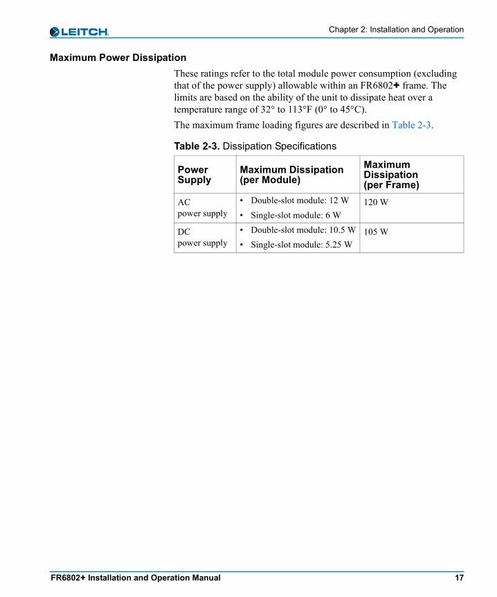
Table 4-2. 6802+PS AC Power Supply
Item SpecificationSize 1.45 x 11.25 x 3.35 in. (3.68 x 28.58 x 8.51 cm)
Weight 1.5 lbs (0.68 kg)
Load step response Recovery to 1% of nominal within 1 msec
Minimum load No load
Ripple and noise <3% of nominal voltage
Over-voltage protection 120% ±10% of nominal output voltage (13.6 V output only)
Temperature range 32°F (0°C) to 113°F (45°C)
Input Specifications
Input voltage 100 to 250 V AC (±10%)
Frequency 47 to 63 Hz
Input current • 2 A rms maximum at 90 V AC, 120 W output power
• 0.75 A rms maximum at 274 V AC, 120 W output power
FR6802+ Installation and Operation Manual 49
Chapter 4: Specifications
Inrush current(maximum peak)
25 A
Efficiency >75% at 117 V AC, 120 W output (typical)
Power factor • >0.90 at 130 W output power• 100 to 250 V AC input voltage
Output Specifications
Output voltages • V Out to V Out_RET: +13.6 V (±3%)• V Out to DGND: +6.8 V (±3%)• V Out_RET to DGND: -6.8 V (±3%)
Output current (maximum load)
• +6.8 V to -6.8 V (9.6 A)• +6.8 V to DGND (15.0 A)• -6.8 V to DGND (10.0 A)
Output power limit • +6.8 V to -6.8 V: 160 W ±15%• +6.8 V to DGND (17.0 A): 120 W ±10%• -6.8 V to DGND (12.5 A): 85 W ±10%
Output power 130 W, combined maximum
Start-up time All outputs are above lower limit within one second of application of input power
Hold-up time >16 msec at 130 W output power at any input voltage within the specified range
Ramp-up time • All outputs are above lower limit within 100 msec of initiated ramp-up time
• Voltage rise on all outputs is monotonic with <5% overshoot
EMC Compliant with FCC part 15 Class A, EN 55103-1 and EN 55103-2
Safety Meets UL 60950, CAN/CSA 22.2 No. 60950 and EN 60950
Table 4-2. 6802+PS AC Power Supply (Continued)
Item Specification

50 FR6802+ Installation and Operation Manual
Chapter 4: Specifications
6802+PS48
Table 4-3. 6802+PS48 DC Power Supply
Item SpecificationSize 1.45 x 11.25 x 3.35 in. (3.68 x 28.58 x 8.51
cm)
Weight 1.5 lbs (0.68 kg)
Ripple <1% pk-to-pk on all outputs
Operating temperature range 32°F (0°C) to 113°F (45°C) at full rated output
Inputs -36 to -72 VDC
Outputs • +6.3 V @ 10 A maximum• -6.4 V @ 7 A maximum
Initial setting • +6.8 V @ 5 A (adjustable)• -6.8 V @ 4 A (not adjustable but
typical)
Output power (with forced air cooling)
• 65 W maximum for +6.5 V output• 45 W maximum for -6.5 V output
Output power (without forced air cooling))
• 45 W maximum for +6.5 V output• 35 W maximum for -6.5 V output
Maximum total power • 105 W with forced air cooling• 50 W without fans
Load regulation The power supply is soft-regulated to support redundant operation with power sharing

FR6802+ Installation and Operation Manual 51
Chapter 4: Specifications
Line regulation >1% over full input range
Transient response <1.2 msec for recovery to within 2% for a step current change of 50-100% of rated
Protection • Inrush current limiting• Input transient protection• Short circuit protection on all outputs• Reverse input voltage protection• Input fuse
EMC Compliant with FCC part 15 Class A, EN 55103-1 and EN 55103-2
Safety Meets UL 60950, CAN/CSA 22.2 No. 60950 and EN 60950
Table 4-3. 6802+PS48 DC Power Supply (Continued)
Item Specification

52 FR6802+ Installation and Operation Manual
Chapter 4: Specifications

FR6802+ Installation and Operation Manual 53
Appendix A
Servicing Instructions
OverviewAttempts to make repairs to frame components—other than the procedures described in this chapter—will result in the voiding of the product’s warranty.Servicing instructions for the FR6802+ are limited to replacing a resource card.
PROCEDURETHESE SERVICING INSTRUCTIONS ARE FOR USE BY QUALIFIED SERVICE PERSONNEL ONLY. TO REDUCE THE RISK OF ELECTRIC SHOCK DO NOT PERFORM ANY SERVICING, OTHER THAN THAT CONTAINED IN THE OPERATING INSTRUCTIONS, UNLESS YOU ARE QUALIFIED TO DO SO.
The following topics are described in this chapter:• “Battery Use Caution” on page 54• “Fuse Replacement Caution” on page 55• “Replacing a Resource Card” on page 56

54 FR6802+ Installation and Operation Manual
Appendix A: Servicing Instructions
Battery Use Caution
CAUTION: DANGER OF EXPLOSION IF BATTERY IS INCORRECTLY PLACED. REPLACE ONLY WITH THE SAME OR EQUIVALENT TYPE RECOMMENDED BY THE MANUFACTURER. DISCARD USED BATTERIES ACCORDING TO THE MANUFACTURER’S INSTRUCTIONS.
FinlandVAROITUS: Paristo voi rajahtaa, jos se on virheellisesti asennettu. Vaihda paristo ainoastaan valmistajan suosittelemaan tyyppun. Havita kaytetty paristo valmistajan ohjeiden mukaisesti.
SwedenVARNING: Explosionsfara vid felaktigt batteribyte. Anvand samma batterityp eller en eller en ekvivalent typ som rekommenderas av tillverkaren. Kassera anvant batteri enligt fabrikantens instruktion.
Denmark
Korea
Advarsel! Lithiumbatteri. Eksplosionsfare ved fejlagtig handtering. Udskiftning ma kun ske med batteri af samme fabrikat oq type. Lever det brugte batteri tilbage till leverandoren.

FR6802+ Installation and Operation Manual 55
Appendix A: Servicing Instructions
Fuse Replacement Caution
CAUTION: FOR CONTINUED PROTECTION AGAINST RISK OF FIRE, REPLACE ONLY WITH THE SAME TYPE OF FUSE.
FrenchATTENTION: REMPLACER UNIQUEMENT PAR UN FUSIBLE DE MEME TYPE.
Table A-1. Fuses and Markings
List of Fuses MarkingF1 (6802+ AC power supply) T 3.15 A H 250 V
F1 (6802+PS48 DC power supply)
F 5A 250 V
F1, F2 (back connectors) T 2A 63 V or3A 15 V (resettable fuses)

56 FR6802+ Installation and Operation Manual
Appendix A: Servicing Instructions
Replacing a Resource CardIf a failure occurs, your customer service representative may recommend that you upgrade or replace the resource card that comes with your FR6802+ frame.
Removing an Existing Resource CardTo remove an existing resource card, follow these steps:1. Pull out the finger-release screws on the right and left sides of the
front panel, and then open it.2. Locate the resource card on the left side of the frame, beside the
power supply.3. Insert a screwdriver into the card-removal hole on the resource
card, and then pull the resource card out of its slot. See Figure A-1.
Figure A-1. Removing a Resource Card
Installing a New Resource Card1. Pull out the finger-release screws on the right and left sides of the
front panel, and then open it.2. Slide the new card into the frame.3. Close the front panel.
Insert a screwdriver into this hole

FR6802+ Installation and Operation Manual 57
Index
KeywordsSymbols+Pilot Lite software application 11
Numerics2RU frame options 36800+ product line 26800/6800+ compatibility 36800/7000 series frames, installing modules 256802+PS and 6802+PS48
description 9installation and usage 43–46specifications 48–51
AAC power supply, maximum power ratings 14AC/DC
connections 32power supply description 9
accessories 3adjustable parameters 41alarms
power supply 46state reporting 10
ambient temperature 16assembly, fan 8
Bback panel
description 7types 3
battery use caution 54BNC coaxial cable connections 11board controls 39
Ccable support bar, installing 18card-edge controls 39caution
battery use 54fuse replacement 55
CCSnetwork connections 36software application 12
clipping parameters 40Command Control System (see "CCS") 12communications
control network 34frame 11
compliance information viconfigurations, frame 3, 11, 12connections
CCS network 36

58 FR6802+ Installation and Operation Manual
Index
genlock 33GPI alarm relay to monitoring system 36system 32
control and monitor features 4, 10, 11control network, identifying frames 35controls, card-edge 39cooling a frame 16
DDC power supply, maximum power ratings 14DC/AC
connections 32power supply description 9
disconnecting a power supply 44downloading Leitch manuals iv
Eelectrical requirements 16EMI gaskets 22Ethernet connection 11, 12extractor handle 23, 25
Ffans
features 4, 8health monitoring 10installing 27replacing a failed fan unit 29
features, product 4FR6802+FA fan assembly 27frame
description 2electrical requirements 16front panel description 6general frame description 4installing 18–20installing fans 27maximum power dissipation 17
power ratings, maximum 14product packages 3rear panel description 7replacing failed fans 29signal flow 5specifications 48status LEDs 38status reporting 10system connections 32–36temperature and ventilation requirements 16
Frame ID rocker switches 35front panel description 6front panel LEDs 38fuse replacement caution 55
Ggenlock connections 33GPI alarm relay, connecting 36
Hhex switch description 39
IICE6800+ Interface Card to Ethernet connections 12identifying frames on the control network 35installing
fans 27frames 18–20frames and modules 14–36modules 21–25new resource card 56power supply 44
LLEDs
power supply 46status 38

FR6802+ Installation and Operation Manual 59
Index
load limitations, frames 16
Mmain features 4manual
ordering ivrevision history iiiwriting conventions iv
maximum frame power ratings 14maximum power dissipation 17modules
installing 21–25making connections 26power consumption 17removing 26
monitor and control features 4, 10, 11monitoring systems, GPI alarm relay 36
Nnetwork
creating a serial communication 34frames 11
Ooperating frames and modules 37–42operating notes 42options, frame 3ordering Leitch manuals ivover-voltage protection (OVP) 45
Ppacking list 15parameter types 40power consumption 17power source, making connections 32power supply
features 4, 9
installation and usage 43–46specifications 48
product description 2–3product packages 3protecting a power supply 45PSU (see "power supply") 9
Rrack-mounting a frame 18read-only parameters 41rear panel description 7rear-support brackets, installing 18redundant power supply 44remote control and monitoring 12removing
fans 29power supply 44resource card 56
replacingfailed fan 29resource card 56
reporting, frame 10resource card
description 10replacement 56
rotary switch description 39RS-232 null modem serial cable connections 11
Ssafety standards viserial communication network, creating 34serial connection 11servicing instructions 53–56shipping information vsignal flow 5specifications 47–51status LEDs 38status, frame 10

60 FR6802+ Installation and Operation Manual
Index
summary of frame operation steps 37switches, control 39symbols, safety visynchronizing signals, genlock connections 33system
configuration, Ethernet control 12configuration, serial control 11connections 32
Ttemperature requirements, frame installation 16termination 11thermal protection 45toggle switch description 40
Uunpacking/shipping information v, 15upgrading frame with fan assembly 27
Vventilation requirements, frame installation 16voltage selection, frames 16
Wwrapping parameters 40
XXLR connector 32

Trademarks and Copyright
AgileVision, BO/S, Broadcast Operating System, CCS, Command Control System, CCS CoPilot, CCS Navigator, CCS Pilot, DigiBus, DigiPeek, Digital Glue, DigiWorks, DPS, DTV Glue, EventWORKS, EZ HD, Genesis, HDTV Glue, Innovision, ISIS, JUNO, LeFont, Leitch, LogoMotion, MediaFile, MediaPort, MIX BOX, Monarch, NEO, the NEO design, OPUS, Panacea, PanelMAPPER, Portal, PROM-Slide, RouterMAPPER, RouterWORKS, StillFile, Still Net, SuiteView, Tekniche, Unilock, VIA, ViewGuard, Whiplash2, Xplus, and Leitch XPRESS are trademarks of Leitch Technology International Inc. which may be registered in the United States, Canada, and/or other countries.
All other trademarks are the property of their respective owners.
Copyright 2003-2005 Leitch Technology International Inc. All rights reserved. This publication supersedes all previous releases. Printed in Canada.
Warranty
Leitch Incorporated ("Leitch") warrants to each original end-user purchaser or licensee (each, a "Customer") of hardware or software products manufactured by Leitch (each, a "Product"), or of non-warranty repair or other services provided by Leitch ("Services"), that each such Product and all such Services will be free from defects in materials and workmanship that adversely affect the Product's performance or the Services' intended purpose for a period (the "Warranty Period") of:
• One year for server hardware Products;
• Two years for non-server, and Desktop hardware Products;
• Ninety days for parts, assemblies and supplies to support hardware Products previously sold to Customers;
• Ninety days for media of software licensed separately from Leitch hardware Products, and encoding created by Leitch as physically affixed on or embedded in such media;
• The same period as the hardware Product warranty for media of software licensed as an integral part of any Leitch hardware Product, and encoding created by Leitch as physically affixed on or embedded in such media
• Ninety days for Services.
Please refer to the current "Leitch Limited Warranty Policy" for a complete description of the warranty provided, including important exclusions and limitations as well as procedures for obtaining warranty service.