Embed Size (px)
Citation preview
3366 IEEE TRANSACTIONS ON IMAGE PROCESSING, VOL. 22, NO. 9, SEPTEMBER 2013
3D High-Efficiency Video Coding for Multi-ViewVideo and Depth Data
Karsten Müller, Senior Member, IEEE, Heiko Schwarz, Detlev Marpe, Senior Member, IEEE, Christian Bartnik,Sebastian Bosse, Heribert Brust, Tobias Hinz, Haricharan Lakshman, Philipp Merkle, Member, IEEE,
Franz Hunn Rhee, Gerhard Tech, Martin Winken, and Thomas Wiegand, Fellow, IEEE
Abstract— This paper describes an extension of the highefficiency video coding (HEVC) standard for coding of multi-view video and depth data. In addition to the known concept ofdisparity-compensated prediction, inter-view motion parameter,and inter-view residual prediction for coding of the dependentvideo views are developed and integrated. Furthermore, fordepth coding, new intra coding modes, a modified motioncompensation and motion vector coding as well as the concept ofmotion parameter inheritance are part of the HEVC extension.A novel encoder control uses view synthesis optimization, whichguarantees that high quality intermediate views can be generatedbased on the decoded data. The bitstream format supportsthe extraction of partial bitstreams, so that conventional 2Dvideo, stereo video, and the full multi-view video plus depthformat can be decoded from a single bitstream. Objective andsubjective results are presented, demonstrating that the proposedapproach provides 50% bit rate savings in comparison withHEVC simulcast and 20% in comparison with a straightforwardmulti-view extension of HEVC without the newly developedcoding tools.
Index Terms— 3D video coding (3DVC), multi-view videoplus depth (MVD), high-efficiency video coding (HEVC),MPEG-H, H.265.
I. INTRODUCTION
3DVIDEO provides a visual experience with depthperception through the usage of special displays
that re-project a three-dimensional scene from slightly dif-ferent directions for the left and right eye. Such displaysinclude stereoscopic displays, which typically show the twoviews that were originally recorded by a stereoscopic camera
Manuscript received January 1, 2013, revised April 12, 2013, acceptedApril 26, 2013. Date of publication May 23, 2013; date of current versionJuly 9, 2013. The associate editor coordinating the review of this manuscriptand approving it for publication was Dr. Debargha Mukherjee.
K. Müller, H. Schwarz, D. Marpe, C. Bartnik, S. Bosse, H. Brust,T. Hinz, H. Lakshman, P. Merkle, H. Rhee, G. Tech, and M. Winkenareare with the Image Processing Department, Fraunhofer Institute forTelecommunications-Heinrich-Hertz-Institut, Berlin 10587, Germany (e-mail:[email protected]; [email protected]; [email protected]; [email protected]; [email protected]; [email protected]; [email protected]; [email protected]; [email protected]; [email protected]; [email protected]; [email protected]).
T. Wiegand is with the Image Processing Department, Fraunhofer Insti-tute for Telecommunications-Heinrich-Hertz-Institut, Berlin 10587, Germany,and also with the Department of Electrical Engineering and ComputerScience, Berlin Institute of Technology, Berlin 10587, Germany (e-mail:[email protected]).
Digital Object Identifier 10.1109/TIP.2013.2264820
system. Here, glasses-based systems are required for multi-user audiences. Especially for 3D home entertainment, newerstereoscopic displays can vary the baseline between the viewsto adapt to different viewing distances. In addition, multi-viewdisplays are available, which show not only a stereo pair, but amultitude of views (typically 20 to more than 50 views) fromslightly different directions. Each user still perceives a viewingpair for the left and right eye. However, a different stereo pairis seen when the viewing position is varied by a small amount.This does not only improve the 3D viewing experience, butallows the perception of 3D video without glasses, also formulti-user audiences [2], [25]. As 3D video content is mainlyproduced as stereo video content, appropriate technology isrequired for generating the additional views from the stereodata for this type of 3D displays. For this purpose, different3D video formats or representations have been considered.
First, video-only formats like conventional stereo video(CSV) and multi-view video (MVV) were proposed.Backward-compatible compression methods for efficient trans-mission of these video-only formats were investigated. Asa result, multi-view video coding (MVC) was standardizedas an extension of H.264/MPEG-4 Advanced Video Coding(AVC) [6], [20], [47], [52], [53]. MVC adds the conceptof disparity-compensated prediction to the H.264/MPEG-4AVC base standard. Due to the corresponding exploitation ofinter-view dependencies, MVC provides a higher compressionefficiency than a separate coding of each view. However, thebit rate that is required for a given level of video quality stillincreases approximately linearly with the number of codedviews [33]. Thus, an MVC-based transmission of a multitudeof video views suitable for multi-view displays is not feasible.
As a next step, 3D video formats with few views and asso-ciated depth information were investigated. The depth infor-mation can be provided through different methods, includingdirect recording by special time-of-flight cameras [28], extrac-tion from computer animated video material from the inher-ent 3D geometry representation [19], or disparity estimation[1], [42]. Such depth-enhanced formats are suitable for generic3D video solutions, where only one format is coded andtransmitted while all necessary views for any 3D display aregenerated from the decoded data, e.g., by means of depthimage based rendering (DIBR) [21], [41].
Parallel developments on improving 2D video coding haveled to the high-efficiency video coding (HEVC) standard,officially approved in April 2013 as ITU-T Recommendation
1057-7149/$31.00 © 2013 IEEE
MÜLLER et al.: 3D HIGH-EFFICIENCY VIDEO CODING 3367
H.265 and ISO/IEC 23008-2 (MPEG-H Part 2), jointly devel-oped by the ITU-T Visual Coding Experts Group (VCEG) andthe ISO/IEC Moving Picture Experts Group (MPEG) [18].Experimental analysis [40] showed that HEVC is capa-ble of achieving the same subjective video quality as theH.264/MPEG-4 AVC High Profile while requiring on averageonly about 50% of the bit rate.
Based on HEVC, this paper proposes a new 3D videocoding framework for depth-enhanced multi-view formats. Thetechnology was submitted as a response to the Call for Pro-posals (CfP) on 3D Video Technology [15], issued by MPEGin order to develop a new standard for high efficiency 3Dvideo delivery. After extensive subjective testing, our proposedtechnology was selected as the starting point of the currentlyon-going collaborative phase in standardization of the 3Dvideo and multi-view extensions of HEVC. The proposedframework is format scalable in the sense that sub-bitstreamsrepresenting a subset of the video views (with or withoutassociated depth data) can be extracted by discarding NALunits from the 3D bitstream and be independently decoded.Furthermore, our proposed methods for depth coding can alsobe used in other hybrid coding architectures, where legacycodecs like H.264/MPEG-4 AVC or MVC are used for thecoding of the video components.
The paper is organized as follows. Section II gives anoverview of the 3D video coding structure and coding tools.The new methods on advanced prediction methods for codingdependent video views are discussed in Section III. Section IVexplains the depth coding approaches, including new intracoding modes, motion vector coding, and motion parameterinheritance. For the optimal encoder control of the proposed3D video codec, view synthesis optimization methods and anencoder-side rendering module are described in Section V.Section VI discusses the decoder-side view synthesis at the3D display. Objective and subjective results are presented inSection VII and conclusions are drawn in Section VIII.
II. OVERVIEW OF 3D VIDEO CODING EXTENSION
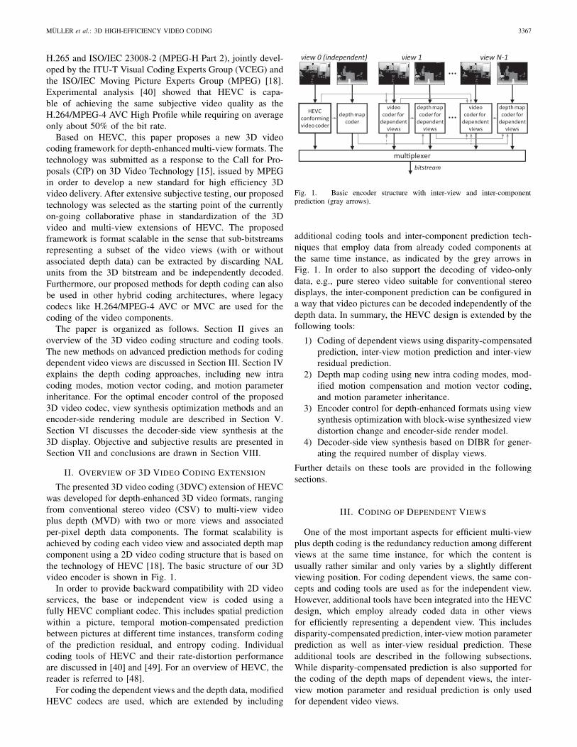
The presented 3D video coding (3DVC) extension of HEVCwas developed for depth-enhanced 3D video formats, rangingfrom conventional stereo video (CSV) to multi-view videoplus depth (MVD) with two or more views and associatedper-pixel depth data components. The format scalability isachieved by coding each video view and associated depth mapcomponent using a 2D video coding structure that is based onthe technology of HEVC [18]. The basic structure of our 3Dvideo encoder is shown in Fig. 1.
In order to provide backward compatibility with 2D videoservices, the base or independent view is coded using afully HEVC compliant codec. This includes spatial predictionwithin a picture, temporal motion-compensated predictionbetween pictures at different time instances, transform codingof the prediction residual, and entropy coding. Individualcoding tools of HEVC and their rate-distortion performanceare discussed in [40] and [49]. For an overview of HEVC, thereader is referred to [48].
For coding the dependent views and the depth data, modifiedHEVC codecs are used, which are extended by including
HEVCconformingvideo coder
depth mapcoder
videocoder for
dependent views
depth mapcoder for
dependentviews
videocoder for
dependent views
depth mapcoder for
dependentviews
mul�plexer
…
…
view 0 (independent) view 1 view N-1
bitstream
Fig. 1. Basic encoder structure with inter-view and inter-componentprediction (gray arrows).
additional coding tools and inter-component prediction tech-niques that employ data from already coded components atthe same time instance, as indicated by the grey arrows inFig. 1. In order to also support the decoding of video-onlydata, e.g., pure stereo video suitable for conventional stereodisplays, the inter-component prediction can be configured ina way that video pictures can be decoded independently of thedepth data. In summary, the HEVC design is extended by thefollowing tools:
1) Coding of dependent views using disparity-compensatedprediction, inter-view motion prediction and inter-viewresidual prediction.
2) Depth map coding using new intra coding modes, mod-ified motion compensation and motion vector coding,and motion parameter inheritance.
3) Encoder control for depth-enhanced formats using viewsynthesis optimization with block-wise synthesized viewdistortion change and encoder-side render model.
4) Decoder-side view synthesis based on DIBR for gener-ating the required number of display views.
Further details on these tools are provided in the followingsections.
III. CODING OF DEPENDENT VIEWS
One of the most important aspects for efficient multi-viewplus depth coding is the redundancy reduction among differentviews at the same time instance, for which the content isusually rather similar and only varies by a slightly differentviewing position. For coding dependent views, the same con-cepts and coding tools are used as for the independent view.However, additional tools have been integrated into the HEVCdesign, which employ already coded data in other viewsfor efficiently representing a dependent view. This includesdisparity-compensated prediction, inter-view motion parameterprediction as well as inter-view residual prediction. Theseadditional tools are described in the following subsections.While disparity-compensated prediction is also supported forthe coding of the depth maps of dependent views, the inter-view motion parameter and residual prediction is only usedfor dependent video views.
3368 IEEE TRANSACTIONS ON IMAGE PROCESSING, VOL. 22, NO. 9, SEPTEMBER 2013
previouspicture
currentpicture
reference view current dependent view
),( RRR vux
d
reference block),( vux
current block
motion vectorof
motion vectorprediction for),( RRR vux ),( vux
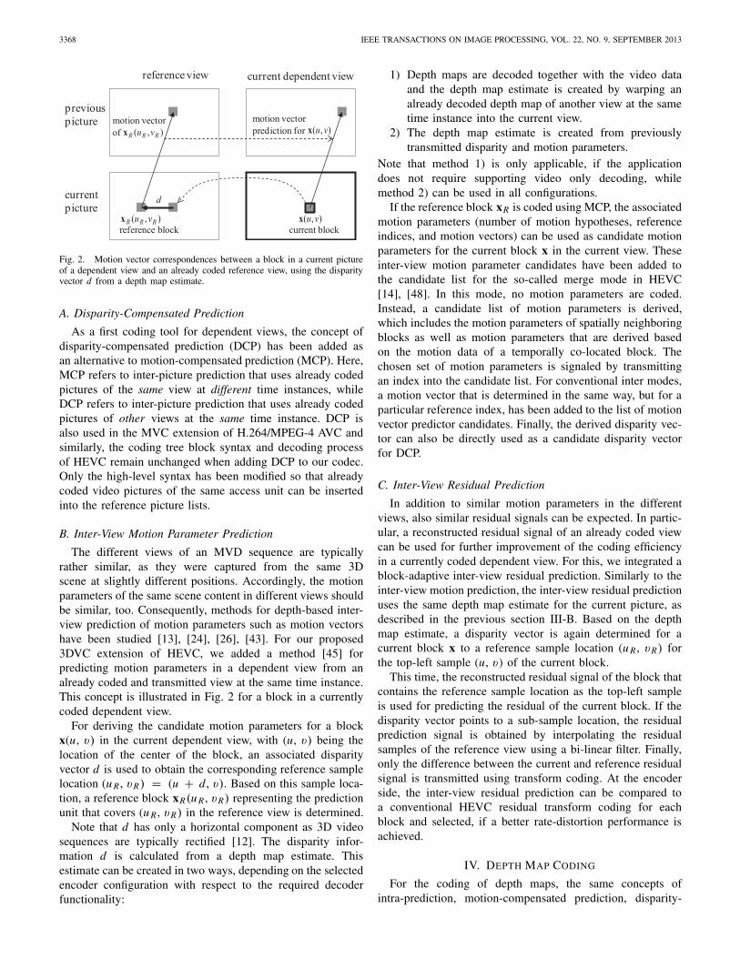
Fig. 2. Motion vector correspondences between a block in a current pictureof a dependent view and an already coded reference view, using the disparityvector d from a depth map estimate.
A. Disparity-Compensated Prediction
As a first coding tool for dependent views, the concept ofdisparity-compensated prediction (DCP) has been added asan alternative to motion-compensated prediction (MCP). Here,MCP refers to inter-picture prediction that uses already codedpictures of the same view at different time instances, whileDCP refers to inter-picture prediction that uses already codedpictures of other views at the same time instance. DCP isalso used in the MVC extension of H.264/MPEG-4 AVC andsimilarly, the coding tree block syntax and decoding processof HEVC remain unchanged when adding DCP to our codec.Only the high-level syntax has been modified so that alreadycoded video pictures of the same access unit can be insertedinto the reference picture lists.
B. Inter-View Motion Parameter Prediction
The different views of an MVD sequence are typicallyrather similar, as they were captured from the same 3Dscene at slightly different positions. Accordingly, the motionparameters of the same scene content in different views shouldbe similar, too. Consequently, methods for depth-based inter-view prediction of motion parameters such as motion vectorshave been studied [13], [24], [26], [43]. For our proposed3DVC extension of HEVC, we added a method [45] forpredicting motion parameters in a dependent view from analready coded and transmitted view at the same time instance.This concept is illustrated in Fig. 2 for a block in a currentlycoded dependent view.
For deriving the candidate motion parameters for a blockx(u, v) in the current dependent view, with (u, v) being thelocation of the center of the block, an associated disparityvector d is used to obtain the corresponding reference samplelocation (u R , vR) = (u + d , v). Based on this sample loca-tion, a reference block xR(u R , vR) representing the predictionunit that covers (u R , vR) in the reference view is determined.
Note that d has only a horizontal component as 3D videosequences are typically rectified [12]. The disparity infor-mation d is calculated from a depth map estimate. Thisestimate can be created in two ways, depending on the selectedencoder configuration with respect to the required decoderfunctionality:
1) Depth maps are decoded together with the video dataand the depth map estimate is created by warping analready decoded depth map of another view at the sametime instance into the current view.
2) The depth map estimate is created from previouslytransmitted disparity and motion parameters.
Note that method 1) is only applicable, if the applicationdoes not require supporting video only decoding, whilemethod 2) can be used in all configurations.
If the reference block xR is coded using MCP, the associatedmotion parameters (number of motion hypotheses, referenceindices, and motion vectors) can be used as candidate motionparameters for the current block x in the current view. Theseinter-view motion parameter candidates have been added tothe candidate list for the so-called merge mode in HEVC[14], [48]. In this mode, no motion parameters are coded.Instead, a candidate list of motion parameters is derived,which includes the motion parameters of spatially neighboringblocks as well as motion parameters that are derived basedon the motion data of a temporally co-located block. Thechosen set of motion parameters is signaled by transmittingan index into the candidate list. For conventional inter modes,a motion vector that is determined in the same way, but for aparticular reference index, has been added to the list of motionvector predictor candidates. Finally, the derived disparity vec-tor can also be directly used as a candidate disparity vectorfor DCP.
C. Inter-View Residual Prediction
In addition to similar motion parameters in the differentviews, also similar residual signals can be expected. In partic-ular, a reconstructed residual signal of an already coded viewcan be used for further improvement of the coding efficiencyin a currently coded dependent view. For this, we integrated ablock-adaptive inter-view residual prediction. Similarly to theinter-view motion prediction, the inter-view residual predictionuses the same depth map estimate for the current picture, asdescribed in the previous section III-B. Based on the depthmap estimate, a disparity vector is again determined for acurrent block x to a reference sample location (u R , vR) forthe top-left sample (u, v) of the current block.
This time, the reconstructed residual signal of the block thatcontains the reference sample location as the top-left sampleis used for predicting the residual of the current block. If thedisparity vector points to a sub-sample location, the residualprediction signal is obtained by interpolating the residualsamples of the reference view using a bi-linear filter. Finally,only the difference between the current and reference residualsignal is transmitted using transform coding. At the encoderside, the inter-view residual prediction can be compared toa conventional HEVC residual transform coding for eachblock and selected, if a better rate-distortion performance isachieved.
IV. DEPTH MAP CODING
For the coding of depth maps, the same concepts ofintra-prediction, motion-compensated prediction, disparity-
MÜLLER et al.: 3D HIGH-EFFICIENCY VIDEO CODING 3369
compensated prediction, and transform coding as for thecoding of the video pictures are used. However, in contrastto natural video, depth maps are characterized by sharp edgesand large regions with nearly constant values [35]. Therefore,different depth coding methods have been studied in the con-text of H.264/MPEG-4 AVC-based 3D video coding, includingwavelet coding [8], [30], mesh-based depth coding [22], sub-sampling of depth data [39] as well as non-rectangular blockpartitioning for depth maps, such as wedgelet or plateletcoding [32], [34] and edge chain coding [7].
As a consequence, new intra coding techniques using so-called depth modeling modes have been developed. In addi-tion, motion-compensated prediction and motion vector codinghave been modified for the coding of depth maps. Furthermore,a depth-coding mode has been developed that directly uses theblock partitioning and motion data from the associated videocomponent. Also, all in-loop filtering techniques of HEVCare disabled for depth map coding. While for encoding ofthe video component the reconstruction quality is directlymeasured from its decoded version, the reconstruction qualityof depth map coding has to be measured indirectly as thequality of synthesized views from decoded video and depthdata. This has been considered for all depth-coding decisionsand modes, described in this section. In particular, a specialencoder process with view synthesis optimization is applied,as described in Section V.
A. Intra Coding Using Depth Modeling Modes
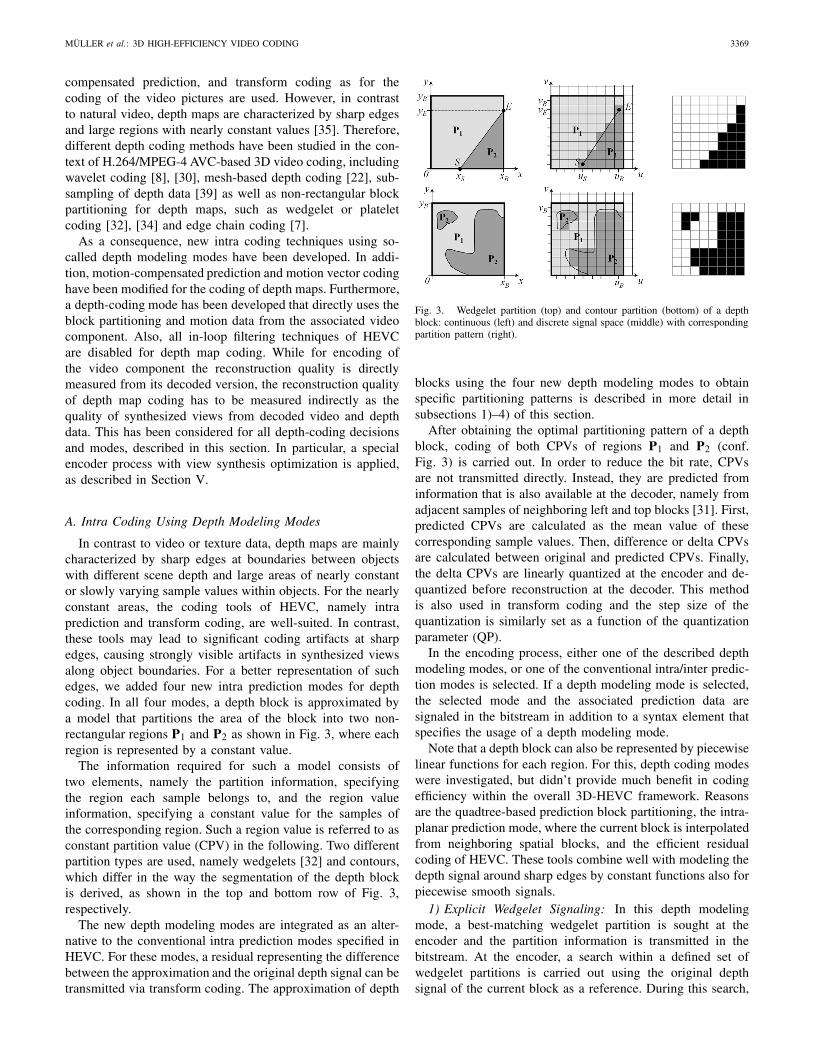
In contrast to video or texture data, depth maps are mainlycharacterized by sharp edges at boundaries between objectswith different scene depth and large areas of nearly constantor slowly varying sample values within objects. For the nearlyconstant areas, the coding tools of HEVC, namely intraprediction and transform coding, are well-suited. In contrast,these tools may lead to significant coding artifacts at sharpedges, causing strongly visible artifacts in synthesized viewsalong object boundaries. For a better representation of suchedges, we added four new intra prediction modes for depthcoding. In all four modes, a depth block is approximated bya model that partitions the area of the block into two non-rectangular regions P1 and P2 as shown in Fig. 3, where eachregion is represented by a constant value.
The information required for such a model consists oftwo elements, namely the partition information, specifyingthe region each sample belongs to, and the region valueinformation, specifying a constant value for the samples ofthe corresponding region. Such a region value is referred to asconstant partition value (CPV) in the following. Two differentpartition types are used, namely wedgelets [32] and contours,which differ in the way the segmentation of the depth blockis derived, as shown in the top and bottom row of Fig. 3,respectively.
The new depth modeling modes are integrated as an alter-native to the conventional intra prediction modes specified inHEVC. For these modes, a residual representing the differencebetween the approximation and the original depth signal can betransmitted via transform coding. The approximation of depth
Fig. 3. Wedgelet partition (top) and contour partition (bottom) of a depthblock: continuous (left) and discrete signal space (middle) with correspondingpartition pattern (right).
blocks using the four new depth modeling modes to obtainspecific partitioning patterns is described in more detail insubsections 1)–4) of this section.
After obtaining the optimal partitioning pattern of a depthblock, coding of both CPVs of regions P1 and P2 (conf.Fig. 3) is carried out. In order to reduce the bit rate, CPVsare not transmitted directly. Instead, they are predicted frominformation that is also available at the decoder, namely fromadjacent samples of neighboring left and top blocks [31]. First,predicted CPVs are calculated as the mean value of thesecorresponding sample values. Then, difference or delta CPVsare calculated between original and predicted CPVs. Finally,the delta CPVs are linearly quantized at the encoder and de-quantized before reconstruction at the decoder. This methodis also used in transform coding and the step size of thequantization is similarly set as a function of the quantizationparameter (QP).
In the encoding process, either one of the described depthmodeling modes, or one of the conventional intra/inter predic-tion modes is selected. If a depth modeling mode is selected,the selected mode and the associated prediction data aresignaled in the bitstream in addition to a syntax element thatspecifies the usage of a depth modeling mode.
Note that a depth block can also be represented by piecewiselinear functions for each region. For this, depth coding modeswere investigated, but didn’t provide much benefit in codingefficiency within the overall 3D-HEVC framework. Reasonsare the quadtree-based prediction block partitioning, the intra-planar prediction mode, where the current block is interpolatedfrom neighboring spatial blocks, and the efficient residualcoding of HEVC. These tools combine well with modeling thedepth signal around sharp edges by constant functions also forpiecewise smooth signals.
1) Explicit Wedgelet Signaling: In this depth modelingmode, a best-matching wedgelet partition is sought at theencoder and the partition information is transmitted in thebitstream. At the encoder, a search within a defined set ofwedgelet partitions is carried out using the original depthsignal of the current block as a reference. During this search,
3370 IEEE TRANSACTIONS ON IMAGE PROCESSING, VOL. 22, NO. 9, SEPTEMBER 2013
the wedgelet partition that yields the minimum distortionbetween the original signal and the wedgelet approximationis selected as the final partitioning pattern for the depth block.For this, the patterns of all possible combinations of start andend point positions are generated and stored in a lookup tablefor each block size prior to the coding process. This wedgeletpattern list contains only unique patterns. The resolution forthe start and end positions (S and E in Fig. 3 top), used forgenerating the wedgelet patterns, depends on the block size.For 16 × 16 and 32 × 32 blocks, the possible start and endpositions are restricted to locations with 2-sample accuracy.For 8 × 8 blocks, full-sample accuracy is used, and for 4 × 4blocks, half-sample accuracy is used.
At the decoder the signal of the block is reconstructedusing the transmitted partition information. Thus, the wedgeletpartition information for this mode is not predicted.
2) Intra-Predicted Wedgelet Partition: In this depth mod-eling mode, the wedgelet partition is predicted from data ofpreviously coded blocks in the same picture, i.e., by intra-picture prediction. For a better approximation, the predictedpartition is refined by varying the line end position. Only theoffset to the line end position is transmitted in the bitstreamand at the decoder the signal of the block is reconstructedusing the partition information that results from combiningthe predicted partition and the transmitted offset.
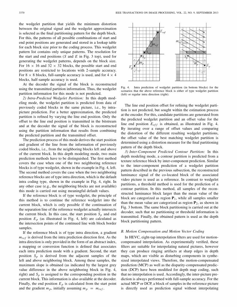
The prediction process of this mode derives the start positionand gradient of the line from the information of previouslycoded blocks, i.e., from the neighboring blocks left and aboveof the current block. In this depth modeling mode, two mainprediction methods have to be distinguished. The first methodcovers the case when one of the two neighboring referenceblocks is of type wedgelet, shown in the example in Fig. 4, left.The second method covers the case when the two neighboringreference blocks are of type intra direction, which is the defaultintra coding type, shown in the example in Fig. 4, right. Inany other case (e.g., the neighboring blocks are not available)this mode is carried out using meaningful default values.
If the reference block is of type wedgelet, the principle ofthis method is to continue the reference wedgelet into thecurrent block, which is only possible if the continuation ofthe separation line of the reference wedgelet actually intersectsthe current block. In this case, the start position Sp and endposition E p (as illustrated in Fig. 4, left) are calculated asthe intersection points of the continued line with block bordersamples.
If the reference block is of type intra direction, a gradientmre f is derived from the intra prediction direction first. As theintra direction is only provided in the form of an abstract index,a mapping or conversion function is defined that associateseach intra prediction mode with a gradient. Second, the startposition Sp is derived from the adjacent samples of theleft and above neighboring block. Among these samples, themaximum slope is obtained (as indicated by the largest greyvalue difference in the above neighboring block in Fig. 4,right) and Sp is assigned to the corresponding position in thecurrent block. This information is also available at the decoder.Finally, the end position E p is calculated from the start pointand the gradient m p, initially assuming m p = mre f .
Fig. 4. Intra prediction of wedgelet partition (in bottom blocks) for thescenarios that the above reference block is either of type wedgelet partition(left) or regular intra direction (right).
The line end position offset for refining the wedgelet parti-tion is not predicted, but sought within the estimation processat the encoder. For this, candidate partitions are generated fromthe predicted wedgelet partition and an offset value for theline end position Eof f is obtained, as illustrated in Fig. 4.By iterating over a range of offset values and comparingthe distortion of the different resulting wedgelet partitions,the offset value of the best matching wedgelet partition isdetermined using a distortion measure for the final partitioningpattern of the depth block.
3) Inter-Component Predicted Contour Partition: In thisdepth modeling mode, a contour partition is predicted from atexture reference block by inter-component prediction. Similarto the inter-component prediction of a wedgelet partitionpattern described in the previous subsection, the reconstructedluminance signal of the co-located block of the associatedvideo picture is used as a reference. In contrast to wedgeletpartitions, a threshold method is used for the prediction of acontour partition. In this method, all samples of the recon-structed luminance block larger than the mean value of theblock are categorized as region P1, while all samples smallerthan the mean value are categorized as region P2, as shown inFig. 3 bottom. The same block partitioning is carried out at thedecoder, such that no partitioning or threshold information istransmitted. Finally, the obtained pattern is used as the depthblock partitioning pattern.
B. Motion Compensation and Motion Vector Coding
In HEVC, eight-tap interpolation filters are used for motion-compensated interpolation. As experimentally verified, thesefilters are suitable for interpolating natural pictures, howeverthey can produce ringing artifacts at sharp edges in depthmaps, which are visible as disturbing components in synthe-sized interpolated views. Therefore, the motion-compensatedprediction (MCP) as well as the disparity-compensated predic-tion (DCP) have been modified for depth map coding, suchthat no interpolation is used. Accordingly, the inter-picture pre-diction is always performed with full-sample accuracy. For theactual MCP or DCP, a block of samples in the reference pictureis directly used as prediction signal without interpolating
MÜLLER et al.: 3D HIGH-EFFICIENCY VIDEO CODING 3371
any intermediate samples. In order to avoid the transmissionof motion and disparity vectors with an unnecessarily highaccuracy, full-sample accurate motion and disparity vectors areused for coding depth maps. The transmitted motion vectordifferences are coded using full-sample instead of quarter-sample precision.
C. Motion Parameter Inheritance
As the motion characteristics for the video and associateddepth map in the MVD format is similar, inter-componentmotion vector prediction has been studied for H.264/MPEG-4AVC in [37], and [11] for non-rectangular wedgelet parti-tioning, as well as in [9] for video and depth coding withH.262/MPEG-2 Video.
Accordingly, a new inter coding mode for depth maps isadded in which the partitioning of a block into sub-blocks andassociated motion parameters are inferred from the co-locatedblock in the associated video picture. Since the motion vectorsof the video signal are given in quarter-sample accuracy,whereas for the depth signal sample-accurate motion vectorsare used, the inherited motion vectors are quantized to full-sample precision. For each block, it can be adaptively decided,whether the partitioning and motion information is inheritedfrom the co-located region of the video picture, or new motiondata is transmitted. For signaling the former case, also denotedas Motion Parameter Inheritance (MPI) mode, we modified themerge mode of HEVC. We extended the list of possible mergecandidates, such that in depth map coding, the first candidaterefers to merging with the corresponding block from the videosignal. The usage of the merge mode syntax has the advantagethat it allows very efficient signaling of the case where MPIis used without transmitting a residual signal, since the skipmode in HEVC also uses the merge candidate list [54].
V. ENCODER CONTROL
One of the main objectives of a video coding standard is toprovide high compression efficiency. However, a video codingstandard only specifies the decoding and parsing processtogether with the bitstream syntax and does not give anyguarantee on the rate-distortion performance of compliantbitstreams. That means, that a corresponding video encodercan be configured in a flexible way to meet any givenconstraints on bit rate, quality, and computational complexity.Often, when evaluating the coding-efficiency capabilities of agiven bitstream syntax, the encoder control is configured in away to provide the best reconstruction quality at a given bitrate or vice versa, the minimum bit rate at a given quality [46].This is equivalent to minimizing the Lagrangian cost functionJ = D + λ·R [3], which weights the distortion D that isobtained by coding a block in a particular mode or with aparticular set of parameters with the number of bits R that isrequired for transmitting all data of that mode or parameter.Thus, D is an inverse measure of the reconstruction quality,while R is directly related to the total bit rate of the codeddata. D and R are connected via the Lagrange multiplier λ thatis usually derived based on the used quantization parameter.D is typically measured as the sum of squared differences
(SSD) or the sum of absolute differences (SAD) between theoriginal and the reconstructed sample values for video data.
Since reconstructed depth maps are only used for the synthe-sis of intermediate views and are not directly viewed, the cod-ing efficiency can be improved by modifying the Lagrangiancost function. Coding errors in depth data cause artifacts insynthesized views and a modified distortion measure for depthcoding is used, as explained in more detail below.
A. View Synthesis Optimization
For coding the depth maps, R is again measured as the totalbit rate of the coded data. The depth distortion, however, hasto be related to the distortion of synthesized views. Therefore,D needs to be calculated as the SSD between synthesizedviews from original and from reconstructed video and depthdata. This is also referred to as synthesized view distortion(SVD) and has been studied recently in [5], [23], [29], [38].Since standard-compliant video encoding algorithms operateblock-based, the mapping of depth distortion to the synthesizedview distortion must be block-based as well. Moreover, thesum of partial distortions (of sub-blocks) must be equal tothe overall distortion of a block to enable an independentdistortion calculation for all partitions of a subdivided block,as hierarchical block structures are common elements ofmodern video coding standards. However, disocclusions andocclusions prevent a bijective mapping of the distorted depthmap areas to distorted areas in the synthesized view. E.g.,areas in the synthesized view, which depend on depth data ofan evaluated block, can become visible due to the distortionsof other depth blocks; or vice versa, the distortion of a depthblock has no effect on the synthesized view, since the block isoccluded there. Hence, an exact mapping between the distor-tion of a block of the depth data and an associated distortion inthe synthesized view is not possible regarding only the depthdata within a currently processed block. Therefore, the SVDmethod needs to be extended to calculate the exact synthesizedview distortion change (SVDC) [50] for a particular renderingalgorithm and intermediate viewing position, as shown in thenext subsection.
B. Synthesized View Distortion Change
In the SVDC method, the change of overall distortion of thesynthesized view depending on the change of the depth datawithin a depth block is calculated while simultaneously alsoconsidering depth data outside that block. For this, the SVDCis defined as distortion difference of two synthesized textures.
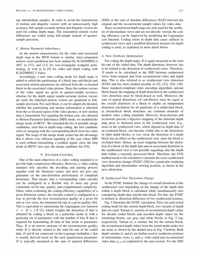
Fig. 5 illustrates the SVDC calculation. First, for each testedcoding mode for the current depth block, two variants of depthdata are used: Variant d1 consists of reconstructed depth valuesfor already coded blocks and uncoded depth values for theremaining blocks, see gray and white blocks in Fig. 5 top,respectively. Variant d2 is similar, but for the current block,the reconstructed depth values from the actual mode under testare used, as shown by the shaded area in Fig. 5 bottom. Bothdepth variants d1 and d2 are further used to synthesize portionsof intermediate views v1 and v2 with coded and reconstructedvideo data tCod as explained in the next section. For the SSD
3372 IEEE TRANSACTIONS ON IMAGE PROCESSING, VOL. 22, NO. 9, SEPTEMBER 2013
Ren.d1
tCod
d2
tCod
Ren.
dOrig
tOrig
Init.Ren.
SSD
SSD
v1
v2
vRefSVDC-
vRef
D1
D2
Depth block withtest coding mode
Original video/ depth block
Coded video/ depth block
Fig. 5. Synthesized view distortion change (SVDC) calculation with respectto a currently tested depth coding mode (Ren.: view synthesis with encoder-side rendering module per block, Init.Ren.: Initial reference view synthesisper picture).
calculation, also the reference portion vRe f is available. It wassynthesized in the initialization phase from uncoded video anddepth data tOrig and dOrig , as described in the next section.Next, both distortions can be calculated: D1 = SSD(v1,vRe f ) for depth variant 1 and D2 = SSD(v2, vRe f ) for depthvariant 2 with the current coding mode under test. Finally,the difference between these values is used as depth distortionmeasure: SVDC = D2 − D1.
C. Encoder-Side Render Model
The computation of SVDC requires rendering functionali-ties in the encoding process, as depth data is used to shift videodata to the correct position in a synthesized view. However,since computational complexity is a critical factor in distortioncalculation, a simplified method has been utilized that allowsminimal re-rendering of only those parts of the synthesizedview that are affected by a depth distortion. This encoder-side render model provides the basic functions of most ren-dering approaches, including sub-pixel accurate warping, holefilling and view blending. Thus, all basic processing steps ofcommon depth-based view synthesis algorithms are consideredby the rate-distortion optimization process at the encoder.Accordingly, the rate-distortion optimization for depth mapscan be performed independently of the final decoder-side viewsynthesis algorithm.
The render model consists of an initialization step for eachpicture, as well as a block-wise iteration with re-renderingand SVDC calculation. During picture-wise initialization, thereference views vRef (see Fig. 5) are synthesized. The block-wise re-rendering first warps the video data block from anoriginal viewing position to the synthesized position usingthe associated depth data. Next, an up-sampling by a factorof 4 of the warped video block is carried out in order toobtain a more accurate value for the full pixel position inthe synthesized view. Small holes of one pixel are filledby linear interpolation from the up-sampled video data. Asthe warping step is aware of the warping direction, larger
holes or disocclusions are filled by the last warped pixel,which is automatically a background pixel, while occludedbackground areas are overridden by foreground. Thus, noz-buffer comparisons, e.g., for front-most pixel detection arerequired. After warping the individual views, weighted view orα-blending with the corresponding block of the second viewcan be carried out [36]. For this, also the second view issynthesized in the picture-wise initialization step [51]. Thesynthesized portion of the intermediate view is then used tocalculate the SSD, using the corresponding portion of thereference view from the initialization step. Finally, the SVDCis obtained as described in the previous section. For viewsynthesis optimization of a set of N intermediate views, thetotal SVDC is calculated by averaging the individual SVDCsat each position.
To enable rate-distortion optimization using SVDC, therender model is integrated into the encoding process for depthdata by replacing the conventional distortion computation withthe SVDC computation in all processing steps related tothe mode decision. Finally, the Lagrangian cost functionalbecomes J = SVDC + ls ·λ·R with ls being a constant scalingfactor. In our experiments, ls = 0.5 gave the best results.The Lagrangian multiplier λ was calculated similar to thecalculation in the HEVC test model encoder.
VI. DEPTH-BASED VIEW SYNTHESIS ALGORITHM
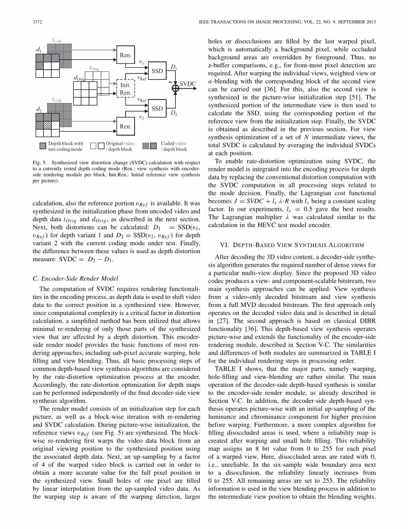
After decoding the 3D video content, a decoder-side synthe-sis algorithm generates the required number of dense views fora particular multi-view display. Since the proposed 3D videocodec produces a view- and component-scalable bitstream, twomain synthesis approaches can be applied: View synthesisfrom a video-only decoded bitstream and view synthesisfrom a full MVD decoded bitstream. The first approach onlyoperates on the decoded video data and is described in detailin [27]. The second approach is based on classical DIBRfunctionality [36]. This depth-based view synthesis operatespicture-wise and extends the functionality of the encoder-siderendering module, described in Section V-C. The similaritiesand differences of both modules are summarized in TABLE Ifor the individual rendering steps in processing order.
TABLE I shows, that the major parts, namely warping,hole-filling and view-blending are rather similar. The mainoperation of the decoder-side depth-based synthesis is similarto the encoder-side render module, as already described inSection V-C. In addition, the decoder-side depth-based syn-thesis operates picture-wise with an initial up-sampling of theluminance and chrominance component for higher precisionbefore warping. Furthermore, a more complex algorithm forfilling disoccluded areas is used, where a reliability map iscreated after warping and small hole filling. This reliabilitymap assigns an 8 bit value from 0 to 255 for each pixelof a warped view. Here, disoccluded areas are rated with 0,i.e., unreliable. In the six-sample wide boundary area nextto a disocclusion, the reliability linearly increases from0 to 255. All remaining areas are set to 255. The reliabilityinformation is used in the view blending process in addition tothe intermediate view position to obtain the blending weights.
MÜLLER et al.: 3D HIGH-EFFICIENCY VIDEO CODING 3373
TABLE I
METHOD COMPARISON BETWEEN DECODER-SIDE DEPTH-BASED VIEW
SYNTHESIS ALGORITHM AND ENCODER-SIDE RENDER MODEL
ProcessingStep
Decoder-Side Depth-BasedView Synthesis
Encoder-Side RenderModel
OperationMode
Picture-wise Block-wise
Up-Sampling 4x for luminance, Not applied
8x for chrominance
WarpingLine-wise directional for
faster occlusion/ disocclusionhandling
Line-wise directionalfor faster occlusion/
disocclusion handling
Interpolationand Hole
Filling
Small holes by interpolation,disocclusions from last
warped pixel as background
Small holes byinterpolation,
disocclusions remain
ReliabilityMap Creation
Reliability map fordissoclusions and object
boundaries, see [36]Not applied
SimilarityEnhancement
Accumulated histogramequalization between views
Not applied
View Blending
α-blending with weights,based on distances to original
viewing positions andreliability map values for
dissocclusion handling
a-blending withweights, based on
distances to originalviewing positions
ChrominanceDecimation
Down-filtering ofchrominance channels, if
necessary for display format(e.g. for 4:2:0)
Not applied
Accordingly, disoccluded areas with a reliability value of 0 arefilled from the other view, while other areas are interpolatedfrom either warped view, according to their blending weights.After blending, the decoder-side depth-based synthesis alsoneeds to adapt to the required display format, e.g., by down-sampling the chrominance channels.
VII. SIMULATION RESULTS
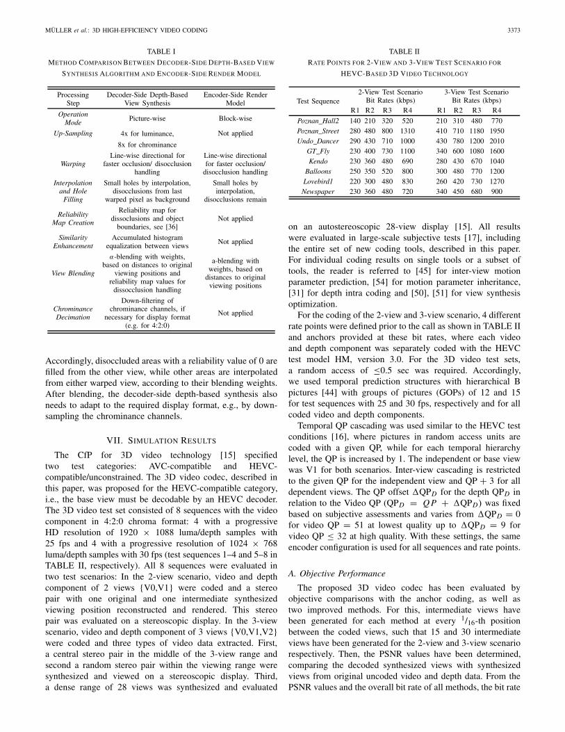
The CfP for 3D video technology [15] specifiedtwo test categories: AVC-compatible and HEVC-compatible/unconstrained. The 3D video codec, described inthis paper, was proposed for the HEVC-compatible category,i.e., the base view must be decodable by an HEVC decoder.The 3D video test set consisted of 8 sequences with the videocomponent in 4:2:0 chroma format: 4 with a progressiveHD resolution of 1920 × 1088 luma/depth samples with25 fps and 4 with a progressive resolution of 1024 × 768luma/depth samples with 30 fps (test sequences 1–4 and 5–8 inTABLE II, respectively). All 8 sequences were evaluated intwo test scenarios: In the 2-view scenario, video and depthcomponent of 2 views {V0,V1} were coded and a stereopair with one original and one intermediate synthesizedviewing position reconstructed and rendered. This stereopair was evaluated on a stereoscopic display. In the 3-viewscenario, video and depth component of 3 views {V0,V1,V2}were coded and three types of video data extracted. First,a central stereo pair in the middle of the 3-view range andsecond a random stereo pair within the viewing range weresynthesized and viewed on a stereoscopic display. Third,a dense range of 28 views was synthesized and evaluated
TABLE II
RATE POINTS FOR 2-VIEW AND 3-VIEW TEST SCENARIO FOR
HEVC-BASED 3D VIDEO TECHNOLOGY
Test Sequence2-View Test Scenario
Bit Rates (kbps)3-View Test Scenario
Bit Rates (kbps)R1 R2 R3 R4 R1 R2 R3 R4
Poznan_Hall2 140 210 320 520 210 310 480 770Poznan_Street 280 480 800 1310 410 710 1180 1950Undo_Dancer 290 430 710 1000 430 780 1200 2010
GT_Fly 230 400 730 1100 340 600 1080 1600Kendo 230 360 480 690 280 430 670 1040
Balloons 250 350 520 800 300 480 770 1200Lovebird1 220 300 480 830 260 420 730 1270Newspaper 230 360 480 720 340 450 680 900
on an autostereoscopic 28-view display [15]. All resultswere evaluated in large-scale subjective tests [17], includingthe entire set of new coding tools, described in this paper.For individual coding results on single tools or a subset oftools, the reader is referred to [45] for inter-view motionparameter prediction, [54] for motion parameter inheritance,[31] for depth intra coding and [50], [51] for view synthesisoptimization.
For the coding of the 2-view and 3-view scenario, 4 differentrate points were defined prior to the call as shown in TABLE IIand anchors provided at these bit rates, where each videoand depth component was separately coded with the HEVCtest model HM, version 3.0. For the 3D video test sets,a random access of ≤0.5 sec was required. Accordingly,we used temporal prediction structures with hierarchical Bpictures [44] with groups of pictures (GOPs) of 12 and 15for test sequences with 25 and 30 fps, respectively and for allcoded video and depth components.
Temporal QP cascading was used similar to the HEVC testconditions [16], where pictures in random access units arecoded with a given QP, while for each temporal hierarchylevel, the QP is increased by 1. The independent or base viewwas V1 for both scenarios. Inter-view cascading is restrictedto the given QP for the independent view and QP + 3 for alldependent views. The QP offset �QPD for the depth QPD inrelation to the Video QP (QPD = Q P + �QPD) was fixedbased on subjective assessments and varies from �QPD = 0for video QP = 51 at lowest quality up to �QPD = 9 forvideo QP ≤ 32 at high quality. With these settings, the sameencoder configuration is used for all sequences and rate points.
A. Objective Performance
The proposed 3D video codec has been evaluated byobjective comparisons with the anchor coding, as well astwo improved methods. For this, intermediate views havebeen generated for each method at every 1/16-th positionbetween the coded views, such that 15 and 30 intermediateviews have been generated for the 2-view and 3-view scenariorespectively. Then, the PSNR values have been determined,comparing the decoded synthesized views with synthesizedviews from original uncoded video and depth data. From thePSNR values and the overall bit rate of all methods, the bit rate
3374 IEEE TRANSACTIONS ON IMAGE PROCESSING, VOL. 22, NO. 9, SEPTEMBER 2013
0%
10%
20%
30%
40%
50%
60%
70%
80%
0,00 0,25 0,50 0,75 1,00 1,25 1,50 1,75 2,00
Bitr
ate
savi
ng [%
]
Virtual Camera Posi�on
2-view: 3DVC vs. anchors 3-view: 3DVC vs. anchors2-view: 3DVC vs. HEVC SC 3-view: 3DVC vs. HEVC SC2-view: 3DVC vs. MV-HEVC 3-view: 3DVC vs. MV-HEVC
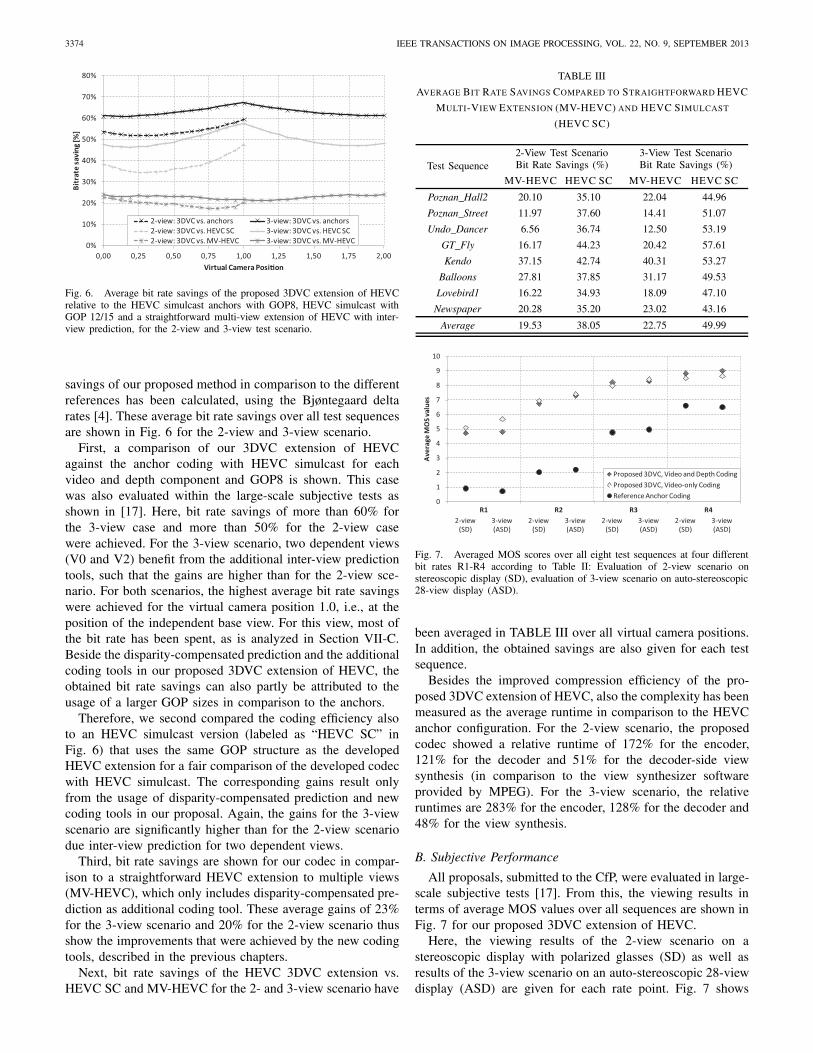
Fig. 6. Average bit rate savings of the proposed 3DVC extension of HEVCrelative to the HEVC simulcast anchors with GOP8, HEVC simulcast withGOP 12/15 and a straightforward multi-view extension of HEVC with inter-view prediction, for the 2-view and 3-view test scenario.
savings of our proposed method in comparison to the differentreferences has been calculated, using the Bjøntegaard deltarates [4]. These average bit rate savings over all test sequencesare shown in Fig. 6 for the 2-view and 3-view scenario.
First, a comparison of our 3DVC extension of HEVCagainst the anchor coding with HEVC simulcast for eachvideo and depth component and GOP8 is shown. This casewas also evaluated within the large-scale subjective tests asshown in [17]. Here, bit rate savings of more than 60% forthe 3-view case and more than 50% for the 2-view casewere achieved. For the 3-view scenario, two dependent views(V0 and V2) benefit from the additional inter-view predictiontools, such that the gains are higher than for the 2-view sce-nario. For both scenarios, the highest average bit rate savingswere achieved for the virtual camera position 1.0, i.e., at theposition of the independent base view. For this view, most ofthe bit rate has been spent, as is analyzed in Section VII-C.Beside the disparity-compensated prediction and the additionalcoding tools in our proposed 3DVC extension of HEVC, theobtained bit rate savings can also partly be attributed to theusage of a larger GOP sizes in comparison to the anchors.
Therefore, we second compared the coding efficiency alsoto an HEVC simulcast version (labeled as “HEVC SC” inFig. 6) that uses the same GOP structure as the developedHEVC extension for a fair comparison of the developed codecwith HEVC simulcast. The corresponding gains result onlyfrom the usage of disparity-compensated prediction and newcoding tools in our proposal. Again, the gains for the 3-viewscenario are significantly higher than for the 2-view scenariodue inter-view prediction for two dependent views.
Third, bit rate savings are shown for our codec in compar-ison to a straightforward HEVC extension to multiple views(MV-HEVC), which only includes disparity-compensated pre-diction as additional coding tool. These average gains of 23%for the 3-view scenario and 20% for the 2-view scenario thusshow the improvements that were achieved by the new codingtools, described in the previous chapters.
Next, bit rate savings of the HEVC 3DVC extension vs.HEVC SC and MV-HEVC for the 2- and 3-view scenario have
TABLE III
AVERAGE BIT RATE SAVINGS COMPARED TO STRAIGHTFORWARD HEVC
MULTI-VIEW EXTENSION (MV-HEVC) AND HEVC SIMULCAST
(HEVC SC)
Test Sequence2-View Test ScenarioBit Rate Savings (%)
3-View Test ScenarioBit Rate Savings (%)
MV-HEVC HEVC SC MV-HEVC HEVC SC
Poznan_Hall2 20.10 35.10 22.04 44.96
Poznan_Street 11.97 37.60 14.41 51.07
Undo_Dancer 6.56 36.74 12.50 53.19
GT_Fly 16.17 44.23 20.42 57.61
Kendo 37.15 42.74 40.31 53.27
Balloons 27.81 37.85 31.17 49.53
Lovebird1 16.22 34.93 18.09 47.10
Newspaper 20.28 35.20 23.02 43.16
Average 19.53 38.05 22.75 49.99
0
1
2
3
4
5
6
7
8
9
10
2-view(SD)
3-view(ASD)
2-view(SD)
3-view(ASD)
2-view(SD)
3-view(ASD)
2-view(SD)
3-view(ASD)
Aver
age
MO
S val
ues
Proposed 3DVC, Video and Depth CodingProposed 3DVC, Video-only CodingReference Anchor Coding
R1 R2 R3 R4
Fig. 7. Averaged MOS scores over all eight test sequences at four differentbit rates R1-R4 according to Table II: Evaluation of 2-view scenario onstereoscopic display (SD), evaluation of 3-view scenario on auto-stereoscopic28-view display (ASD).
been averaged in TABLE III over all virtual camera positions.In addition, the obtained savings are also given for each testsequence.
Besides the improved compression efficiency of the pro-posed 3DVC extension of HEVC, also the complexity has beenmeasured as the average runtime in comparison to the HEVCanchor configuration. For the 2-view scenario, the proposedcodec showed a relative runtime of 172% for the encoder,121% for the decoder and 51% for the decoder-side viewsynthesis (in comparison to the view synthesizer softwareprovided by MPEG). For the 3-view scenario, the relativeruntimes are 283% for the encoder, 128% for the decoder and48% for the view synthesis.
B. Subjective Performance
All proposals, submitted to the CfP, were evaluated in large-scale subjective tests [17]. From this, the viewing results interms of average MOS values over all sequences are shown inFig. 7 for our proposed 3DVC extension of HEVC.
Here, the viewing results of the 2-view scenario on astereoscopic display with polarized glasses (SD) as well asresults of the 3-view scenario on an auto-stereoscopic 28-viewdisplay (ASD) are given for each rate point. Fig. 7 shows
MÜLLER et al.: 3D HIGH-EFFICIENCY VIDEO CODING 3375
0% 10% 20% 30% 40% 50% 60% 70% 80% 90% 100%
R4
R3
R2
R1
Video V1 Video V0 Depth V1 Depth V0
0% 10% 20% 30% 40% 50% 60% 70% 80% 90% 100%
R4
R3
R2
R1
Video V1 Video V0 Video V2 Depth V1 Depth V0 Depth V2
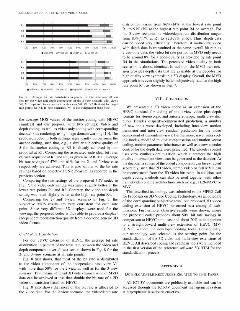
Fig. 8. Average bit rate distribution in percent of total rate over all testsets for the video and depth components of the 2-view scenario with viewsV0, V1 (top) and 3-view scenario with views V0, V1, V2 (bottom) for targetrate points R1-R4. In both scenarios, V1 is the independent base view.
the average MOS values of the anchor coding with HEVCsimulcast and our proposal with two settings: Video anddepth coding, as well as video-only coding with correspondingdecoder-side rendering, using image domain warping [10]. Theproposed codec in both settings significantly outperforms theanchor coding, such that, e.g., a similar subjective quality of5 for the anchor coding at R3 is already achieved by ourproposal at R1. Comparing the associated individual bit ratesof each sequence at R3 and R1, as given in TABLE II, averagebit rate savings of 57% and 61% for the 2- and 3-view caserespectively are achieved. This is also similar to the bit ratesavings based on objective PSNR measure, as reported in theprevious section.
Comparing the two settings of the proposed 3DV codec inFig. 7, the video-only setting was rated slightly better at thelower rate points R1 and R2. Contrary, the video and depthsetting was rated slightly better at the high rate point R4.
Comparing the 2- and 3-view scenario in Fig. 7, thesubjective MOS results are very consistent for each ratepoint. Since very different 3D displays were used for theviewing, the proposed codec is thus able to provide a display-independent reconstruction quality from a decoded generic 3Dvideo format.
C. Bit Rate Distribution
For our 3DVC extension of HEVC, the average bit ratedistribution in percent of the total rate between the video anddepth components over all test sets is shown in Fig. 8 for the2- and 3-view scenario at all rate points.
Fig. 8 first shows, that most of the bit rate is distributedto the video component of the independent base view V1with more than 50% for the 2-view as well as for the 3-viewscenario. That means, efficient 3D video transmission of MVDdata can be achieved at less than double the bit rate of a 2Dvideo transmission based on HEVC.
Fig. 8 also shows that most of the bit rate is allocated tothe video data. For the 2-view scenario, the video/depth rate
distribution varies from 86%/14% at the lowest rate point
R1 to 93%/7% at the highest rate point R4 on average. For
the 3-view scenario the video/depth rate distribution rangesfrom 83%
/17% at R1 to 92%
/8% at R4. Thus, depth data
can be coded very efficiently. Therefore, if multi-view videowith depth data is transmitted at the same overall bit rate asvideo-only data, the video bit rate portion in MVD only needsto be around 8% for a good-quality as provided by rate pointR4 in the simulations. The perceived video quality in bothscenarios is almost identical. In addition, the MVD transmis-sion provides depth data that are available at the decoder forhigh quality view synthesis in a 3D display. Overall, the MVDapproach was even slightly better subjectively rated at the highrate point R4, as shown in Fig. 7.
VIII. CONCLUSION
We presented a 3D video codec as an extension of theHEVC standard for coding of multi-view video plus depthformats for stereoscopic and autostereoscopic multi-view dis-plays. Besides disparity-compensated prediction, a numberof new tools were developed, including inter-view motionparameter and inter-view residual prediction for the videocomponent of dependent views. Furthermore, novel intra cod-ing modes, modified motion compensation and motion vectorcoding, motion parameter inheritance as well as a new encodercontrol for the depth data were presented. The encoder controluses view synthesis optimization, which guarantees that highquality intermediate views can be generated at the decoder. Atthe decoder, a subset of the coded components can be extractedseparately, such that 2D video, stereo video or full MVD canbe reconstructed from the 3D video bitstream. In addition, ourdepth coding methods can also be used together with otherhybrid video coding architectures such as, e.g., H.264/AVC orMVC.
The described technology was submitted to the MPEG Callfor Proposals on 3D Video Coding Technology. As an outcomeof the corresponding subjective tests, our proposed 3D videocoding extension of HEVC performed best among all sub-missions. Furthermore, objective results were shown, wherethe proposed codec provides about 50% bit rate savings incomparison to HEVC simulcast and about 20% in comparisonto a straightforward multi-view extension of HEVC (MV-HEVC) without the developed coding tools. Consequently,our technology was selected as the starting point for thestandardization of the 3D video and multi-view extensions ofHEVC. All described coding and synthesis tools were includedin the first version of the reference software 3D-HTM for thestandardization process.
APPENDIX A
DOWNLOADABLE RESOURCES RELATED TO THIS PAPER
All JCT-3V documents are publically available and can beaccessed through the JCT-3V document management systemat http://phenix.it-sudparis.eu/jct3v/.
3376 IEEE TRANSACTIONS ON IMAGE PROCESSING, VOL. 22, NO. 9, SEPTEMBER 2013
ACKNOWLEDGMENT
The authors would like to thank Disney Research Zurichfor providing the view generation technology, which was usedfor rendering output views from decoded video-only data.
They would also like to thank Poznan University of Technol-ogy, Nokia Research, Nagoya University, Gwangju Institute ofScience and Technology, Electronics and TelecommunicationsResearch Institute, MPEG-Korea Forum ETRI for provid-ing the Poznan_Hall, Poznan_Street, Undo_Dancer, GT_Fly,Kendo, Balloons, Lovebird1 and Newspaper 3D video test datasets.
REFERENCES
[1] N. Atzpadin, P. Kauff, and O. Schreer, “Stereo analysis by hybrid recur-sive matching for real-time immersive video conferencing,” IEEE Trans.Circuits Syst. Video Technol., Special Issue Immersive Telecommun.,vol. 14, no. 3, pp. 321–334, Mar. 2004.
[2] P. Benzie, J. Watson, P. Surman, I. Rakkolainen, K. Hopf, H. Urey,V. Sainov, and C. V. Kopylow, “A survey of 3DTV Displays: Techniquesand technologies,” IEEE Trans. Circuits Syst. Video Technol., vol. 17,no. 11, pp. 1647–1658, Nov. 2007.
[3] T. Berger, Rate Distortion Theory. Englewood Cliffs, NJ, USA: Prentice-Hall, 1971.
[4] G. Bjøntegaard, “Calculation of average PSNR differences between RD-curves,” in Proc. VCEG-M33 Meeting, 2001, pp. 1–4.
[5] G. Cheung, J. Ishida, A. Kubota, and A. Ortega, “Transform domainsparsification of depth maps using iterative quadratic programming,” inProc. IEEE Int. Conf. Image Process., Brussels, Belgium, Sep. 2011,pp. 129–132.
[6] Y. Chen, Y.-K. Wang, K. Ugur, M. Hannuksela, J. Lainema, andM. Gabbouj, “The emerging MVC standard for 3D video services,”EURASIP J. Adv. Signal Process., vol. 2009, no. 1, p. 8, Jan. 2009.
[7] I. Daribo, G. Cheung, and D. Florencio, “Arithmetic edge coding forarbitrarily shaped sub-block motion prediction in depth video compres-sion,” in Proc. IEEE Int. Conf. Image Process., Orlando, FL, USA,Oct. 2012, pp. 1541–1544.
[8] I. Daribo, C. Tillier, and B. Pesquet-Popescu, “Adaptive wavelet codingof the depth map for stereoscopic view synthesis,” in Proc. IEEE Int.Workshop Multimedia Signal Process., Cairns, Australia, Oct. 2008,pp. 34–39.
[9] I. Daribo, C. Tillier, and B. Pesquet-Popescu, “Motion vector sharingand bit rate allocation for 3D video-plus-depth coding,” EURASIP J. Adv.Signal Process., Special Issue 3DTV, vol. 2009, no. 258920, pp. 1–13,Jan. 2009, doi:10.1155/2009/258920.
[10] M. Farre, O. Wang, M. Lang, M. Stefanoski, A. Hornung, and A. Smolic,“Automatic content creation for multiview autostereoscopic displaysusing image domain warping,” in Proc. IEEE Int. Conf. MultimediaExposit., Barcelona, Spain, Jul. 2011, pp. 1–6.
[11] R. Ferreira, E. Hung, R. de Queiroz, and D. Mukherjee, “Effi-ciency improvements for a geometric-partition-based video coder,”in Proc. IEEE Int. Conf. Image Process., Cairo, Egypt, Nov. 2009,pp. 1009–1012.
[12] A. Fusiello, E. Trucco, and A. Verri, “A compact algorithm for recti-fication of stereo pairs,” Mach. Vis. Appl., vol. 12, no. 1, pp. 16–22,Jan. 2000.
[13] X. Guo, Y. Lu, F. Wu, and W. Gao, “Inter-view direct mode for multiviewvideo coding,” IEEE Trans. Circuits Syst. Video Technol., vol. 16, no. 12,pp. 1527–1532, Dec. 2006.
[14] P. Helle, S. Oudin, B. Bross, D. Marpe, M. O. Bici, K. Ugur, J. Jung,G. Clare, and T. Wiegand, “Block merging for quadtree-based parti-tioning in HEVC,” IEEE Trans. Circuits Syst. Video Technol., vol. 22,no. 12, pp. 1720–1731, Dec. 2012.
[15] Call for Proposals on 3D Video Coding Technology, Standard ISO/IECJTC1/SC29/WG11, Mar. 2011.
[16] Joint Call for Proposals for Video Coding Technology, Standard ISO/IECJTC1/SC29/WG11, Jan. 2010.
[17] Report of Subjective Test Results from the Call for Proposals on 3DVideo Coding, Standard ISO/IEC JTC1/SC29/WG11, Nov. 2011.
[18] Text of ISO/IEC DIS 23008-2 High Efficiency Video Coding, StandardISO/IEC JTC1/SC29/WG11, July 2012.
[19] The Virtual Reality Modeling Language, Standard ISO/IEC DIS 14772-1, Apr. 1997.
[20] Advanced Video Coding for Generic Audiovisual Services, StandardISO/IEC JTC 1, Mar. 2012.
[21] P. Kauff, N. Atzpadin, C. Fehn, M. Müller, O. Schreer, A. Smolic,and R. Tanger, “Depth map creation and image based rendering foradvanced 3DTV services providing interoperability and scalability,”Signal Process., Image Commun., Special Issue 3DTV, vol. 22, no. 2,pp. 217–234, Feb. 2007.
[22] S.-Y. Kim and Y.-S. Ho, “Mesh-based depth coding for 3D video usinghierarchical decomposition of depth maps,” in Proc. IEEE Int. Conf.Image Process., San Antonio, TX, USA, Sep. 2007, pp. V-117–V-120.
[23] W.-S. Kim, A. Ortega, P. Lai, D. Tian, and C. Gomila, “Depth map cod-ing with distortion estimation of rendered view,” Proc. SPIE, vol. 7543,pp. 75430B-1–75430B-10, Jan. 2010.
[24] J. Konieczny and M. Domanski, “Depth-based inter-view prediction ofmotion vectors for improved multiview video coding,” in Proc. IEEETrue Vis., Capture, Transmiss. Display 3D Video, Tampere, Finland,Jun. 2010, pp. 1–4.
[25] J. Konrad and M. Halle, “3-D displays and signal processing,” IEEESignal Process. Mag., vol. 24, no. 6, pp. 97–111, Nov. 2007.
[26] H.-S. Koo, Y.-J. Jeon, and B.-M. Jeon, “Motion skip mode for MVC,”ITU-T and ISO/IEC JTC1, Hangzhou, China, Tech. Rep. JVT-U091,Oct. 2006.
[27] M. Lang, A. Hornung, O. Wang, S. Poulakos, A. Smolic, and M. Gross,“Nonlinear disparity mapping for stereoscopic 3D,” ACM Trans. Graph.,vol. 29, no. 3, pp. 75:1–75:10, Jul. 2010.
[28] E.-K. Lee, Y.-K. Jung, and Y.-S. Ho, “3-D video generation using fore-ground separation and disocclusion detection,” in Proc. IEEE True Vis.,Capture, Transmiss. Display 3D Video, Tampere, Finland, Jun. 2010,pp. 1–4.
[29] Y. Liu, Q. Huang, S. Ma, D. Zhao, and W. Gao, “Joint video/depthrate allocation for 3D video coding based on view synthesis distortionmodel,” Signal Process., Image Commun., vol. 24, no. 8, pp. 666–681,Aug. 2009.
[30] M. Maitre and M. N. Do, “Shape-adaptive wavelet encoding of depthmaps,” in Proc. Picture Coding Symp., Chicago, IL, USA, May 2009,pp. 1–4.
[31] P. Merkle, C. Bartnik, K. Müller, D. Marpe, and T. Wiegand, “3Dvideo: Depth coding based on inter-component prediction of blockpartitions,” in Proc. Picture Coding Symp., Krakow, Poland, May 2012,pp. 149–152.
[32] P. Merkle, Y. Morvan, A. Smolic, D. Farin, K. Müller, P. H. N. de With,and T. Wiegand, “The effects of multiview depth video compressionon multiview rendering,” Signal Process., Image Commun., vol. 24,nos. 1–2, pp. 73–88, Jan. 2009.
[33] P. Merkle, A. Smolic, K. Müller, and T. Wiegand, “Efficient predictionstructures for multiview video coding,” IEEE Trans. Circuits Syst. VideoTechnol., vol. 17, no. 11, pp. 1461–1473, Nov. 2007.
[34] Y. Morvan, D. Farin, and P. H. N. de With, “Platelet-based codingof depth maps for the transmission of multiview images,” Proc. SPIE,vol. 6055, p. 60550K, Jan. 2006.
[35] K. Müller, P. Merkle, and T. Wiegand, “3D video representation usingdepth maps,” Proc. IEEE, Special Issue 3D Media Displays, vol. 99,no. 4, pp. 643–656, Apr. 2011.
[36] K. Müller, A. Smolic, K. Dix, P. Merkle, P. Kauff, and T. Wiegand,“View synthesis for advanced 3D video systems,” EURASIP J. ImageVideo Process., Special Issue 3D Image Video Process., vol. 2008,no. 438148, pp. 1–11, 2008, doi:10.1155/2008/438148.
[37] H. Oh and Y. Ho, “H.264-based depth map sequence coding usingmotion information of corresponding texture video,” in Proc. Pacific-RimSymp. Image Video Technol., Hsinchu, Taiwan, Dec. 2006, pp. 898–907.
[38] B. T. Oh, J. Lee, and D.-S. Park, “Depth map coding based on syn-thesized view distortion function,” IEEE J. Sel. Topics Signal Process.,vol. 5, no. 7, pp. 1344–1352, Nov. 2011.
[39] K.-J. Oh, S. Yea, A. Vetro, and Y.-S. Ho, “Depth reconstruction filterand down/up sampling for depth coding in 3-D video,” IEEE SignalProcess. Lett., vol. 16, no. 9, pp. 747–750, Sep. 2009.
[40] J.-R. Ohm, G. J. Sullivan, H. Schwarz, T. K. Tan, and T. Wiegand,“Comparison of the coding efficiency of video coding standards—Including high efficiency video coding (HEVC),” IEEE Trans. CircuitsSyst. Video Technol., vol. 22, no. 12, pp. 1669–1684, Dec. 2012.
[41] A. Redert, M. O. de Beeck, C. Fehn, W. Ijsselsteijn, M. Pollefeys,L. Van Gool, E. Ofek, I. Sexton, and P. Surman, “ATTEST-advancedthree-dimensional television system techniques,” in Proc. Int. Symp. 3DData Process., Visualizat. Transmiss., Jun. 2002, pp. 313–319.
[42] D. Scharstein and R. Szeliski, “A taxonomy and evaluation of dense two-frame stereo correspondence algorithms,” Int. J. Comput. Vis., vol. 47,no. 1, pp. 7–42, May 2002.
MÜLLER et al.: 3D HIGH-EFFICIENCY VIDEO CODING 3377
[43] H. Schwarz, C. Bartnik, S. Bosse, H. Brust, T. Hinz, H. Lakshman,D. Marpe, P. Merkle, K. Muller, H. Rhee, G. Tech, M. Winken,and T. Wiegand, “3D video coding using advanced prediction, depthmodeling, and encoder control methods,” in Proc. Picture Coding Symp.,Krakow, Poland, May 2012, pp. 1–4.
[44] H. Schwarz, D. Marpe, and T. Wiegand, “Analysis of hierarchicalB pictures and MCTF,” in Proc. IEEE Int. Conf. Multimedia Expo,Toronto, ON, Canada, Jul. 2006, pp. 1929–1932.
[45] H. Schwarz and T. Wiegand, “Inter-view prediction of motion datain multiview video coding,” in Proc. Picture Coding Symp., Krakow,Poland, May 2012, pp. 101–104.
[46] C. E. Shannon, “A mathematical theory of communication,” Bell Syst.Tech. J., vol. 27, no. 3, pp. 2163–2177, Jul. 1948.
[47] S. Shimizu, M. Kitahara, H. Kimata, K. Kamikura, and Y. Yashima,“View scalable multiview video coding using 3-D warping with depthmap,” IEEE Trans. Circuits Syst. Video Technol., vol. 17, no. 11,pp. 1485–1495, Nov. 2007.
[48] G. J. Sullivan, J.-R. Ohm, W.-J. Han, and T. Wiegand, “Overview of thehigh efficiency video coding (HEVC) standard,” IEEE Trans. CircuitsSyst. Video Technol., vol. 22, no. 12, pp. 1649–1668, Dec. 2012.
[49] T. K. Tan, A. Fujibayashi, Y. Suzuki, and J. Takiue, “[AHG 8] objectiveand subjective evaluation of HM5.0,” Joint Collaborative Team on VideoCoding, San Jose, USA, Tech. Rep. JCTVC-H0116, Feb. 2012.
[50] G. Tech, H. Schwarz, K. Müller, and T. Wiegand, “3D video codingusing the synthesized view distortion change,” in Proc. Picture CodingSymp., Krakow, Poland, May 2012, pp. 25–28.
[51] G. Tech, H. Schwarz, K. Müller, and T. Wiegand, “Effects of synthesizedview distortion based 3D video coding on the quality of interpolated andextrapolated views,” in Proc. ICME IEEE Int. Conf. Multimedia Exposit.,Melbourne, Australia, Jul. 2012, pp. 634–639.
[52] A. Vetro, T. Wiegand, and G. J. Sullivan, “Overview of the stereo andmultiview video coding extensions of the H.264/AVC standard,” in Proc.IEEE, Special Issue 3D Media Displays, vol. 99, no. 4, pp. 626–642,Apr. 2011.
[53] T. Wiegand, G. J. Sullivan, G. Bjøntegaard, and A. Luthra, “Overviewof the H.264/AVC video coding standard,” IEEE Trans. Circuits Syst.Video Technol., vol. 13, no. 7, pp. 560–576, Jul. 2003.
[54] M. Winken, H. Schwarz, and T. Wiegand, “Motion vector inheritancefor high efficiency 3D video plus depth coding,” in Proc. Picture CodingSymp., Krakow, Poland, May 2012, pp. 53–56.
Karsten Müller (M’98–SM’07) received the Dr.-Ing. degree in electrical engineering and Dipl.-Ing.degree from the Technical University of Berlin,Berlin, Germany, in 2006 and 1997, respectively.
He has been with the Fraunhofer Institutefor Telecommunications, Heinrich-Hertz-Institut,Berlin, since 1997, where he is currently the Headof the 3-D Coding Group, Image Processing Depart-ment. His current research interests include repre-sentation, coding and reconstruction of 3-D scenesin free viewpoint video scenarios and coding, multi-
view applications, and combined 2-D/3-D similarity analysis. He has beeninvolved in international standardization activities, successfully contributingto the ISO/IEC Moving Picture Experts Group for work items on multi-view,multi-texture, and 3-D Video Coding. He co-chaired an ad hoc group on 3-Dvideo coding from 2003 to 2012.
Heiko Schwarz received the Dipl.-Ing. degree inelectrical engineering and the Dr.-Ing. degree fromthe University of Rostock, Rostock, Germany, in1996 and 2000, respectively.
He joined the Image and Video Coding Group,Fraunhofer Institute for Telecommunications–Heinrich Hertz Institute, Berlin, Germany, in1999. He has contributed successfully to thestandardization activities of the ITU-T VideoCoding Experts Group (ITU-T SG16/Q.6-VCEG)and the ISO/IEC Moving Picture Experts Group
(ISO/IEC JTC 1/SC 29/WG 11—MPEG).Dr. Schwarz has been a Co-Editor of ITU-T Rec. H.264 and ISO/IEC
14496-10 and a Software Coordinator for the SVC reference software. Hehas been the Co-Chair of several ad hoc groups of the Joint Video Team ofITU-T VCEG and ISO/IEC MPEG.
Detlev Marpe (M’00–SM’08) received the Dipl.-Math. degree (Hons.) from the Technical Universityof Berlin (TUB), Berlin, Germany, in 1990, andthe Dr.-Ing. degree from the University of Rostock,Rostock, Germany, in 2004.
Before joining the Fraunhofer Institute forTelecommunications–Heinrich Hertz Institute (HHI),Berlin, in 1999, he was a Research Assistant withTUB, University of Applied Sciences, Berlin, andUniversity Hospital Charité, Berlin. He is currentlythe Head of the Image and Video Coding Group,
Fraunhofer HHI. He has successfully contributed to the standardizationactivities of the ITU-T Visual Coding Experts Group, the ISO/IEC JointPhotographic Experts Group, and the ISO/IEC Moving Picture Experts Groupfor still image and video coding. In the development of the H.264/MPEG-4 AVC standard, he was a Chief Architect of the CABAC entropy codingscheme, as well as one of the main technical and editorial contributors tothe so-called fidelity range extensions with the addition of the High Profilein H.264/MPEG-4 AVC. He was one of the key people in designing thebasic architecture of scalable video coding and multi-view video coding asalgorithmic and syntactical extensions of H.264/MPEG-4 AVC. During therecent development of the H.265/MPEG-H HEVC base standard, he madesignificant contributions to the design of its fundamental building blocks.He has authored or co-authored more than 200 publications in the areasof image coding and signal processing. He holds numerous internationallyissued patents and patent applications. His current research interests includestill image and video coding, signal processing for communications as wellas computer vision, and information theory.
Dr. Marpe was a co-recipient of two Technical Emmy Awards as a KeyContributor and a co-editor of the H.264/MPEG-4 AVC standard in 2008 and2009. He was nominated for the German Future Prize 2012 and he receivedthe 2011 Karl Heinz Beckurts Award, the 2009 Best Paper Award of the IEEECircuits and Systems Society, the Joseph-von-Fraunhofer Prize in 2004, andthe Best Paper Award of the German Society for Information Technology in2004. As a co-founder of the Berlin-based daviko GmbH, he received thePrime Prize of the 2001 Multimedia Start-Up Competition of the GermanFederal Ministry of Economics and Technology.
Christian Bartnik received the Dipl. Ing. (FH)degree in communications engineering from theUniversity of Applied Sciences, Berlin, Germany,in 2009.
In 2008, he joined the Image and VideoCoding Group, Fraunhofer Institute forTelecommunications–Heinrich Hertz Institute,Berlin. His current research interests include videocoding, 3-D video, and compression of multiviewvideo plus depth scenes.
Sebastian Bosse received the Diploma degree fromRWTH Aachen University, Aachen, Germany, in2008.
He is currently with the Image and VideoCoding Group, Fraunhofer Institute forTelecommunications–Heinrich Hertz Institute,Berlin, Germany. His current research interestsinclude video compression, computer vision, andhuman visual perception.
Heribert Brust received the Dipl.-Ing. degree inelectrical engineering from the Technical Universityof Berlin, Germany, in 2009.
He has been with the Fraunhofer Institutefor Telecommunications, Heinrich Hertz InstituteBerlin, Berlin, Germany, since 2007. His currentresearch interests include video coding, 3-D televi-sion, and stereoscopic video for mobile devices.
3378 IEEE TRANSACTIONS ON IMAGE PROCESSING, VOL. 22, NO. 9, SEPTEMBER 2013
Tobias Hinz received the Dipl.-Ing. degree in elec-trical engineering from the Technical University ofBerlin, Berlin, Germany, in 1999.
He is currently a Research Engineer with theDepartment of Image Processing, Fraunhofer Insti-tute for Telecommunications–Heinrich Hertz Insti-tute, Berlin. His current research interests includeprocessing, coding and transmission of video andaudio content, as well as software design and opti-mization.
Haricharan Lakshman is a Research Associatewith Fraunhofer HHI, Berlin, Germany, and thePh.D. degree with the Technical University of Berlin,Berlin, and the Bachelor of Engineering degree fromNITK Surathkal, Surathkal, India, in 2002. From2002 to 2006, he was an Engineer with IttiamSystems, Bangalore, India. He received the M.S.degree from the University of Erlangen-Nuremberg,Erlangen, Germany, in 2008, while as a ResearchAssistant with Fraunhofer IIS, Erlangen. From 2011to 2012, he was a Visiting Researcher with Stanford
University, Stanford, CA, USA. His current research interests include imageprocessing, video coding, 3-D video, and semantic analysis.
Philipp Merkle (S’06–M’12) received the Dipl.-Ing.degree in electrical engineering from the TechnicalUniversity of Berlin, Berlin, Germany, in 2006.
He joined the Fraunhofer Institute for Telecommu-nications, Heinrich-Hertz-Institut, Berlin, in 2003,and he has been a Research Associate since 2006.He has been involved in several projects focusedon multiview video coding, 3-D television, freeviewpoint video, and 3-D scene reconstruction. Hiscurrent research interests include 3-D video, repre-sentation and compression of multiview video plus
depth scenes, free viewpoint video, and 2-D and 3-D video-based rendering.He has been involved in ISO standardization activities where he contributedto the development of the MPEG-4 multiview video coding standard.
Philipp Merkle received the “Rudolf-Urtel Award” of the German Societyfor Technology in TV and Cinema (FKTG) for his work on multiview videocoding in 2006.
Franz Hunn Rhee received the Dipl.-Ing. degree inelectrical engineering from the Technical Universityof Hamburg-Harburg, Hamburg, Germany, in 2008.
He is currently with the 3-D Coding Group,Fraunhofer Institute for Telecommunications - Hein-rich Hertz Institute, Berlin, Germany. His currentresearch interests include signal processing, in par-ticular multi-view video coding.
Gerhard Tech received the Dipl.-Ing. degree inelectrical engineering from RWTH Aachen Univer-sity of Technology, Aachen, Germany, where he hasbeen involved in medical image processing and noisereduction.
He joined the Fraunhofer Institute for Telecommu-nications, Heinrich-Hertz-Institut, Berlin, Germany,in 2008, and he is a Research Assistant. His cur-rent research interests include video and imagecoding and processing, including stereo, multiview,and video plus depth representations. He has been
involved in MPEG activities.
Martin Winken received the Diploma degree incomputer engineering from the Technical Universityof Berlin, Berlin, Germany, in 2006. Currently, heis pursuing the Ph.D. degree in video compressiontechnology.
He is currently a Research Engineer with theImage and Video Coding Group, Fraunhofer Institutefor Telecommunications–Heinrich Hertz Institute,Berlin. He has published conference contributionsand contributed to standardization activity in videocompression technology.
Thomas Wiegand (M’05–SM’08–F’11) receivedthe Dipl.-Ing. degree in electrical engineering fromthe Technical University of Hamburg-Harburg, Ham-burg, Germany, in 1995, and the Dr.-Ing. degreefrom the University of Erlangen-Nuremberg, Erlan-gen, Germany, in 2000.
He is currently a Professor with the Departmentof Electrical Engineering and Computer Science,Berlin Institute of Technology, Berlin, Germany, aChairing the Image Communication Laboratory, andis jointly heading the Image Processing Department,
Fraunhofer Institute for Telecommunications–Heinrich Hertz Institute, Berlin.He joined the Heinrich Hertz Institute as the Head of the Image Commu-nication Group, Image Processing Department in 2000. Since 1995, he hasbeen an active participant in standardization for multimedia with successfulsubmissions to ITU-T VCEG, ISO/IEC MPEG, 3GPP, DVB, and IETF. Hiscurrent research interests include video processing and coding, multimediatransmission, and computer vision and graphics.
Dr. Wiegand was a recipient of the SPIE VCIP Best Student Paper Awardin 1998, and the Fraunhofer Award and the ITG Award of the GermanSociety for Information Technology in 2004. He co-chaired for developmentof the H.264/MPEG-4 AVC standard have been recognized by the 2008 ATASPrimetime Emmy Engineering Award and by a pair of NATAS Technologyand Engineering Emmy Awards. In 2009, he received the Innovations Awardof the Vodafone Foundation, the EURASIP Group Technical AchievementAward, and the Best Paper Award of the IEEE TRANSACTIONS ON CIRCUITSAND SYSTEMS FOR VIDEO TECHNOLOGY. In 2010, he received the EduardRhein Technology Award. In 2011, he received the Best Paper Award ofEURASIP and the Karl Heinz Beckurts Award. In October 2000, he wasthe Associated Rapporteur of ITU-T VCEG. In December 2001, he was theAssociated Rapporteur/Co-Chair of the JVT. In February 2002, he was theEditor of the H.264/MPEG-4 AVC video coding standard and its extensions(FRExt and SVC). From 2005 to 2009, he was the Co-Chair of MPEG Video.He is a recipient of the 2012 IEEE Masaru Ibuka Technical Field Award.