Embed Size (px)
Citation preview
341958
Environment Sensing Kit (Contents)
170-pin Breadboard
1x 2x16 LCD display I2C1602
1x 3-axis tilt accelerometer
1x Acrylic mounting plate
1x Joystick module
1x LM35 Temp Sensor
1x Microphone sound sensor
1x Mounting hardware
1x Photo Resistor Light Sensor
1x Smoke sensor
1x Soil Moisture sensor
1x Temp & Humidity
1x Ultrasonic
1x Water Level / Rain sensor
40x Pin headers
5x Sensor header wires
Arduino Uno R3 compatible board
Dupont connector wires
1x USB cable
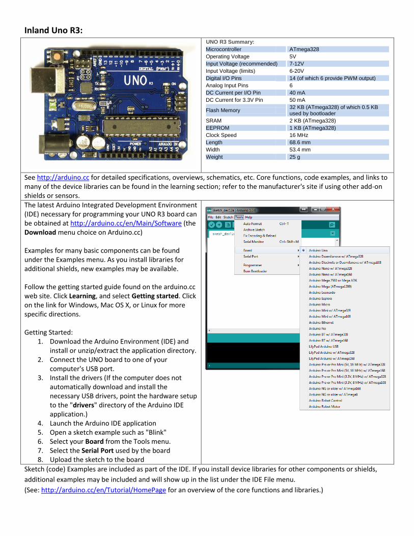
Inland Uno R3:
UUUNO R3 Summary:
Microcontroller ATmega328
Operating Voltage 5V
Input Voltage (recommended) 7-12V
Input Voltage (limits) 6-20V
Digital I/O Pins 14 (of which 6 provide PWM output)
Analog Input Pins 6
DC Current per I/O Pin 40 mA
DC Current for 3.3V Pin 50 mA
Flash Memory 32 KB (ATmega328) of which 0.5 KB used by bootloader
SRAM 2 KB (ATmega328)
EEPROM 1 KB (ATmega328)
Clock Speed 16 MHz
Length 68.6 mm
Width 53.4 mm
Weight 25 g
See http://arduino.cc for detailed specifications, overviews, schematics, etc. Core functions, code examples, and links to many of the device libraries can be found in the learning section; refer to the manufacturer's site if using other add-on shields or sensors.
The latest Arduino Integrated Development Environment (IDE) necessary for programming your UNO R3 board can be obtained at http://arduino.cc/en/Main/Software (the Download menu choice on Arduino.cc) Examples for many basic components can be found under the Examples menu. As you install libraries for additional shields, new examples may be available. Follow the getting started guide found on the arduino.cc web site. Click Learning, and select Getting started. Click on the link for Windows, Mac OS X, or Linux for more specific directions. Getting Started:
1. Download the Arduino Environment (IDE) and install or unzip/extract the application directory.
2. Connect the UNO board to one of your computer's USB port.
3. Install the drivers (If the computer does not automatically download and install the necessary USB drivers, point the hardware setup to the "drivers" directory of the Arduino IDE application.)
4. Launch the Arduino IDE application 5. Open a sketch example such as "Blink" 6. Select your Board from the Tools menu. 7. Select the Serial Port used by the board 8. Upload the sketch to the board
Sketch (code) Examples are included as part of the IDE. If you install device libraries for other components or shields,
additional examples may be included and will show up in the list under the IDE File menu.
(See: http://arduino.cc/en/Tutorial/HomePage for an overview of the core functions and libraries.)
Components:
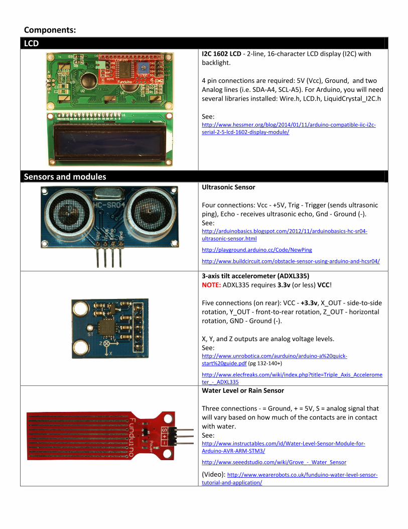
LCD
I2C 1602 LCD - 2-line, 16-character LCD display (I2C) with backlight. 4 pin connections are required: 5V (Vcc), Ground, and two Analog lines (i.e. SDA-A4, SCL-A5). For Arduino, you will need several libraries installed: Wire.h, LCD.h, LiquidCrystal_I2C.h See: http://www.hessmer.org/blog/2014/01/11/arduino-compatible-iic-i2c-serial-2-5-lcd-1602-display-module/
Sensors and modules
Ultrasonic Sensor Four connections: Vcc - +5V, Trig - Trigger (sends ultrasonic ping), Echo - receives ultrasonic echo, Gnd - Ground (-). See: http://arduinobasics.blogspot.com/2012/11/arduinobasics-hc-sr04-ultrasonic-sensor.html
http://playground.arduino.cc/Code/NewPing
http://www.buildcircuit.com/obstacle-sensor-using-arduino-and-hcsr04/
3-axis tilt accelerometer (ADXL335) NOTE: ADXL335 requires 3.3v (or less) VCC! Five connections (on rear): VCC - +3.3v, X_OUT - side-to-side rotation, Y_OUT - front-to-rear rotation, Z_OUT - horizontal rotation, GND - Ground (-). X, Y, and Z outputs are analog voltage levels. See: http://www.unrobotica.com/aurduino/arduino-a%20quick-start%20guide.pdf (pg 132-140+)
http://www.elecfreaks.com/wiki/index.php?title=Triple_Axis_Accelerometer_-_ADXL335
Water Level or Rain Sensor Three connections - = Ground, + = 5V, S = analog signal that will vary based on how much of the contacts are in contact with water. See: http://www.instructables.com/id/Water-Level-Sensor-Module-for-Arduino-AVR-ARM-STM3/
http://www.seeedstudio.com/wiki/Grove_-_Water_Sensor
(Video): http://www.wearerobots.co.uk/funduino-water-level-sensor-
tutorial-and-application/
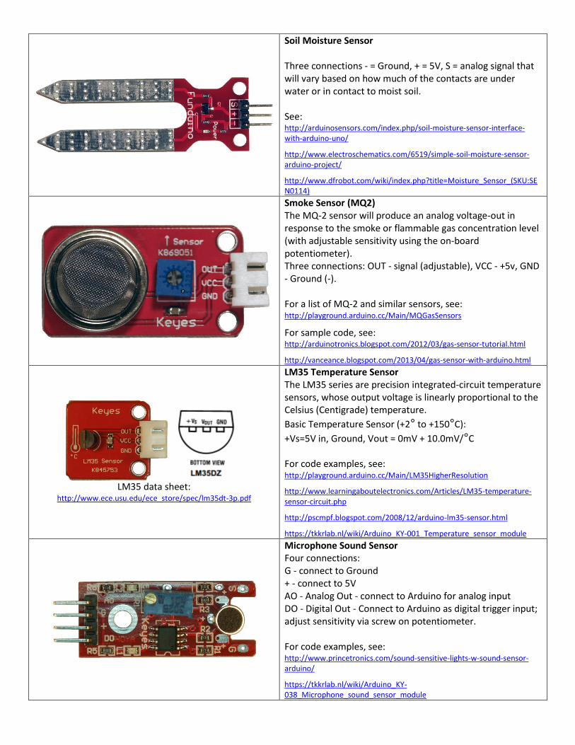
Soil Moisture Sensor Three connections - = Ground, + = 5V, S = analog signal that will vary based on how much of the contacts are under water or in contact to moist soil. See: http://arduinosensors.com/index.php/soil-moisture-sensor-interface-with-arduino-uno/
http://www.electroschematics.com/6519/simple-soil-moisture-sensor-arduino-project/
http://www.dfrobot.com/wiki/index.php?title=Moisture_Sensor_(SKU:SEN0114)
Smoke Sensor (MQ2) The MQ-2 sensor will produce an analog voltage-out in response to the smoke or flammable gas concentration level (with adjustable sensitivity using the on-board potentiometer). Three connections: OUT - signal (adjustable), VCC - +5v, GND - Ground (-). For a list of MQ-2 and similar sensors, see: http://playground.arduino.cc/Main/MQGasSensors
For sample code, see: http://arduinotronics.blogspot.com/2012/03/gas-sensor-tutorial.html
http://vanceance.blogspot.com/2013/04/gas-sensor-with-arduino.html
LM35 data sheet:
http://www.ece.usu.edu/ece_store/spec/lm35dt-3p.pdf
LM35 Temperature Sensor The LM35 series are precision integrated-circuit temperature sensors, whose output voltage is linearly proportional to the Celsius (Centigrade) temperature.
Basic Temperature Sensor (+2° to +150°C):
+Vs=5V in, Ground, Vout = 0mV + 10.0mV/°C For code examples, see: http://playground.arduino.cc/Main/LM35HigherResolution
http://www.learningaboutelectronics.com/Articles/LM35-temperature-sensor-circuit.php
http://pscmpf.blogspot.com/2008/12/arduino-lm35-sensor.html
https://tkkrlab.nl/wiki/Arduino_KY-001_Temperature_sensor_module
Microphone Sound Sensor Four connections: G - connect to Ground + - connect to 5V AO - Analog Out - connect to Arduino for analog input DO - Digital Out - Connect to Arduino as digital trigger input; adjust sensitivity via screw on potentiometer. For code examples, see: http://www.princetronics.com/sound-sensitive-lights-w-sound-sensor-arduino/
https://tkkrlab.nl/wiki/Arduino_KY-038_Microphone_sound_sensor_module
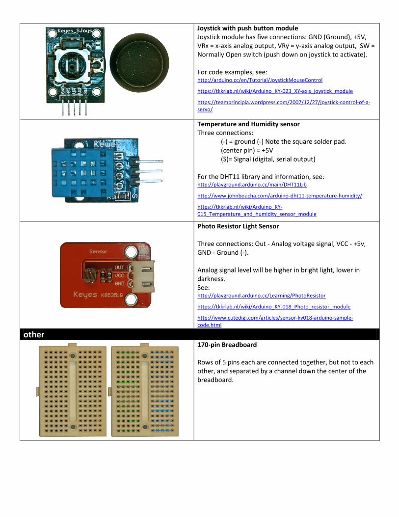
Joystick with push button module Joystick module has five connections: GND (Ground), +5V, VRx = x-axis analog output, VRy = y-axis analog output, SW = Normally Open switch (push down on joystick to activate). For code examples, see: http://arduino.cc/en/Tutorial/JoystickMouseControl
https://tkkrlab.nl/wiki/Arduino_KY-023_XY-axis_joystick_module
https://teamprincipia.wordpress.com/2007/12/27/joystick-control-of-a-servo/
Temperature and Humidity sensor Three connections:
(-) = ground (-) Note the square solder pad. (center pin) = +5V (S)= Signal (digital, serial output)
For the DHT11 library and information, see: http://playground.arduino.cc/main/DHT11Lib
http://www.johnboucha.com/arduino-dht11-temperature-humidity/
https://tkkrlab.nl/wiki/Arduino_KY-015_Temperature_and_humidity_sensor_module
Photo Resistor Light Sensor Three connections: Out - Analog voltage signal, VCC - +5v, GND - Ground (-). Analog signal level will be higher in bright light, lower in darkness. See: http://playground.arduino.cc/Learning/PhotoResistor
https://tkkrlab.nl/wiki/Arduino_KY-018_Photo_resistor_module
http://www.cutedigi.com/articles/sensor-ky018-arduino-sample-code.html
other
170-pin Breadboard Rows of 5 pins each are connected together, but not to each other, and separated by a channel down the center of the breadboard.
Additional Resources: Several sites have hook-up and information and code examples on a variety of sensors, similar to, and including the ones found in this kit. Some sensors may be loose components or integrated into different board designs. If the documented sensor uses the same electronic component, then any code sketch documented may work with the sensors found in your kit. However, depending on the circuit design, the adjustments or sensitivity range may need to be modified slightly to achieve the desired result. Sites documenting these and other sensors include:
Arduino Playground Examples and additional libraries (code sketches available from the IDE File, Examples menu): http://www.arduino.cc/en/Tutorial/HomePage
Arduino Playground Tutorials: http://playground.arduino.cc/Learning/Tutorials
Forum.HobbyComponents.com: http://forum.hobbycomponents.com/viewtopic.php?f=73&t=1320
LinkSprite Wiki - Advanced Sensors Kit for Arduino: http://linksprite.com/wiki/index.php5?title=Advanced_Sensors_Kit_for_Arduino
TkkrLab.nl (Tukkerlab)Wiki: https://tkkrlab.nl/wiki/Arduino_37_sensors
University of Rhode Island (PDF coursework): http://www.ele.uri.edu/courses/ele205/Arduino%20-%20Learning.pdf
Freeduino.org: http://www.freeduino.org/
Arduino for Projects (PDF with 1193 projects): http://duino4projects.com/arduino-projects-pdf/
Lady Ada - Introduction to Arduino- step-by-step lessons: http://www.ladyada.net/learn/arduino/index.html
Tronixstuf Arduino Tutorials: http://tronixstuff.com/tutorials/
Earthshine Electronics Beginners Guide to Arduino: https://docs.google.com/file/d/0Bw_ruMOtRDDgNXI3OTFGZXhIZ2c/edit?usp=sharing
Sheepdog's Guide to Arduino Programming: http://sheepdogguides.com/arduino/FA1main.htm