Embed Size (px)
Citation preview
Technical Manual
flex™
1.1 General 1.2 Certi�cation1.3 Properties
1. Product Information
2. General Requirements
2.1 Framing2.2 Fasteners2.3 Fastener Fixing Distance2.4 Jointing2.5 Finishes2.6 Maintenance
3. Suspended Ceiling3.1 General3.2 Support Grid & Board Size3.3 Framing System3.4 Accessories
4. Fixed Ceiling Eaves / So�t Linings
4.1 General4.2 Board Layout4.3 Installation4.4 Joints & Wall Junctions4.5 Details
5. External Wall & Gable End Cladding5.1 General5.2 Good Building Practices5.3 Installation5.4 Joints & Corners5.5 Details
6. Roof Sarking / Underlay
6.1 General6.2 Design Consideration6.3 Installation6.4 Details
7. Flooring
7.1 General7.2 Design Consideration7.3 Installation7.4 Joints & Intersection Details7.5 Finishes7.6 Waterproo�ng7.7 Details
8. Permanent Formwork8.1 General8.2 Design Consideration8.3 Cutting & Installation8.4 Details
9. Working Instruction
9.1 Cutting9.2 Penetration9.3 Handling & Storage
10. Accessories
02
03
06
07
08
11
13
16
17
18
Cont
ents Multi Functions Board
Eco-friendly �bre cement �at sheets for ceiling, eaves & so�t lining, wall cladding, �ooring, partition, roof sarking, water tank support and permanent formwork.
flex™
1 Product Information
1.1 General
1.1.1 Composition is a lightweight, autoclaved cellulose �bre cement sheet manufactured in accordance with the:-
• MS 1296 – Fibre-cement �at sheets – Product speci�cation and test methods (First revision)
The basic composition is portland cement, cellulose �bre, ground sand and water. A variety of standard lengths and widths are made available to suit speci�c application. sheets do not contain asbestos �bre or glass �bre.
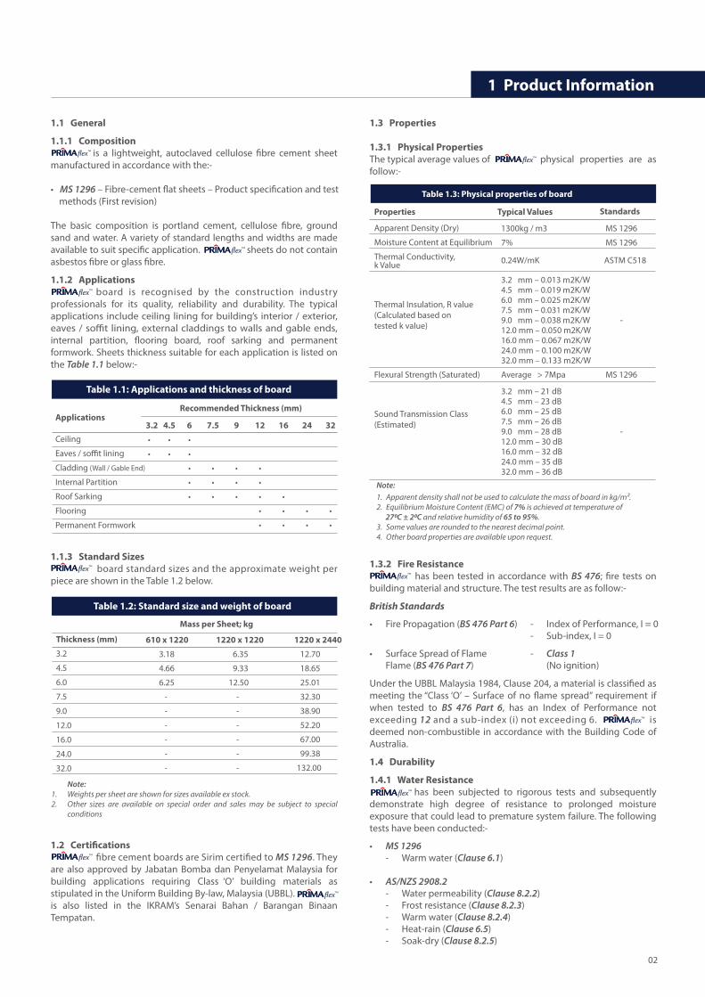
1.1.2 Applications board is recognised by the construction industry professionals for its quality, reliability and durability. The typical applications include ceiling lining for building’s interior / exterior, eaves / so�t lining, external claddings to walls and gable ends, internal partition, �ooring board, roof sarking and permanent formwork. Sheets thickness suitable for each application is listed on the Table 1.1 below:-
1.1.3 Standard Sizes board standard sizes and the approximate weight per piece are shown in the Table 1.2 below.
1.2 Certi�cations �bre cement boards are Sirim certi�ed to MS 1296. They are also approved by Jabatan Bomba dan Penyelamat Malaysia for building applications requiring Class ‘O’ building materials as stipulated in the Uniform Building By-law, Malaysia (UBBL). is also listed in the IKRAM’s Senarai Bahan / Barangan Binaan Tempatan.
1.3 Properties
1.3.1 Physical Properties The typical average values of physical properties are as follow:-
1.3.2 Fire Resistance has been tested in accordance with BS 476; �re tests on building material and structure. The test results are as follow:-
British Standards
• Fire Propagation (BS 476 Part 6) - Index of Performance, I = 0 - Sub-index, I = 0
• Surface Spread of Flame - Class 1 Flame (BS 476 Part 7) (No ignition)
Under the UBBL Malaysia 1984, Clause 204, a material is classi�ed as meeting the “Class ‘O’ – Surface of no �ame spread” requirement if when tested to BS 476 Part 6, has an Index of Performance not exceeding 12 and a sub-index (i) not exceeding 6. is deemed non-combustible in accordance with the Building Code of Australia.
1.4 Durability
1.4.1 Water Resistance has been subjected to rigorous tests and subsequently demonstrate high degree of resistance to prolonged moisture exposure that could lead to premature system failure. The following tests have been conducted:-
• MS 1296 - Warm water (Clause 6.1)
• AS/NZS 2908.2 - Water permeability (Clause 8.2.2) - Frost resistance (Clause 8.2.3) - Warm water (Clause 8.2.4) - Heat-rain (Clause 6.5) - Soak-dry (Clause 8.2.5)
flex™
flex™
flex™
flex™
flex™
flex™
flex™
flex™
flex™
flex™
Ceiling
Eaves / so�t lining
Cladding (Wall / Gable End)
Internal Partition
Roof Sarking
Flooring
Permanent Formwork
3.2 4.5 6 7.5 9 12 16 24 32
• • •
• • •
• • • •
• • • •
• • • • •
• • • •
• • • •
Recommended Thickness (mm)Applications
Table 1.1: Applications and thickness of board
Table 1.3: Physical properties of board
Typical ValuesProperties Standards
1300kg / m3 MS 1296
7% MS 1296
0.24W/mK ASTM C518
3.2 mm – 0.013 m2K/W4.5 mm – 0.019 m2K/W6.0 mm – 0.025 m2K/W7.5 mm – 0.031 m2K/W9.0 mm – 0.038 m2K/W -12.0 mm – 0.050 m2K/W16.0 mm – 0.067 m2K/W24.0 mm – 0.100 m2K/W32.0 mm – 0.133 m2K/W
Average > 7Mpa MS 1296
3.2 mm – 21 dB4.5 mm – 23 dB6.0 mm – 25 dB7.5 mm – 26 dB9.0 mm – 28 dB -12.0 mm – 30 dB16.0 mm – 32 dB24.0 mm – 35 dB32.0 mm – 36 dB
Apparent Density (Dry)
Moisture Content at Equilibrium
Thermal Conductivity,k Value
Thermal Insulation, R value(Calculated based on tested k value)
Flexural Strength (Saturated)
Sound Transmission Class(Estimated)
Note:1. Apparent density shall not be used to calculate the mass of board in kg/m2.2. Equilibrium Moisture Content (EMC) of 7% is achieved at temperature of 270C ± 20C and relative humidity of 65 to 95%.3. Some values are rounded to the nearest decimal point.4. Other board properties are available upon request.
Note:Weights per sheet are shown for sizes available ex stock.Other sizes are available on special order and sales may be subject to special conditions
1. 2.
Table 1.2: Standard size and weight of board
610 x 1220 1220 x 1220 1220 x 2440
3.18 6.35 12.70
4.66 9.33 18.65
6.25 12.50 25.01
- - 32.30
- - 38.90
- - 52.20
- - 67.00
- - 99.38
- - 132.00
Mass per Sheet; kg
Thickness (mm)
3.2
4.5
6.0
7.5
9.0
12.0
16.0
24.0
32.0
02
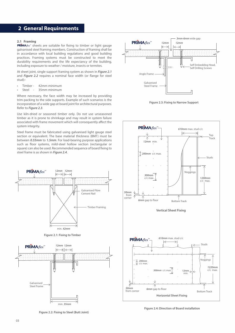
2.1 Framing sheets are suitable for �xing to timber or light gauge galvanised steel framing members. Construction of framing shall be in accordance with local building regulations and good building practices. Framing systems must be constructed to meet the durability requirements and the life expectancy of the building, including exposure to weather / moisture, insects or termites.
At sheet joint, single support framing system as shown in Figure 2.1 and Figure 2.2 requires a nominal face width (or �ange for steel stud):-
• Timber - 42mm minimum• Steel - 35mm minimum
Where necessary, the face width may be increased by providing trim-packing to the side supports. Example of such scenarios is the incorporation of a wide gap at board joint for architectural purposes. Refer to Figure 2.3.
Use kiln-dried or seasoned timber only. Do not use unseasoned timber as it is prone to shrinkage and may result in system failure associated with frame movement which will consequently a�ect the system integrity.
Steel frame must be fabricated using galvanised light gauge steel section or equivalent. The base material thickness (BMT) must be between 0.55mm to 1.5mm. For load-bearing purpose applications such as �oor systems, mild-steel hollow section (rectangular or square) can also be used. Recommended sequence of board �xing to steel frame is as shown in Figure 2.4.
2 General Requirements
flex™
12mm 12mm
min. 42mm
Galvanised Fibre Cement Nail
Timber Framing
Figure 2.1: Fixing to Timber
12mm 12mm
Self Embedding Head,Self Drilling Screws
3mm-6mm wide gap
Angle Frame
Galvanised Steel Frame
Figure 2.2: Fixing to Steel (Butt Joint)
Figure 2.3: Fixing to Narrow Support
12mm 12mm
min. 35mm
Galvanised Steel Frame
1200mm c/c max.
Studs
Top Track
610mm max. stud c/c
12mm min.
200mm c/c max.
300mm c/c max.
50mmfrom
cornerBottom Track
Noggings
6mm gap to �oor
Vertical Sheet Fixing
Figure 2.4: Direction of Board installation
Studs
1220mm c/c max.
610mm max. stud c/c
50mmfrom corner Bottom Track
Noggings
Horizontal Sheet Fixing
6mm gap to �oor
300mm c/c max.
200mm c/c max.
12mm min.
flex™
flex™
flex™
flex™
flex™
03
Unless otherwise speci�ed, frames to receive boards should be straight, true and level. Cladding, lining or �oor board will not straighten excessively distorted or warped frame. Warping may remain visible after boards are applied onto distorted frame. The suggested maximum acceptable frame straightness tolerances are as below:-
- Maximum 3mm over 1200mm length or- Maximum 4mm over 3000mm length, measured in any direction
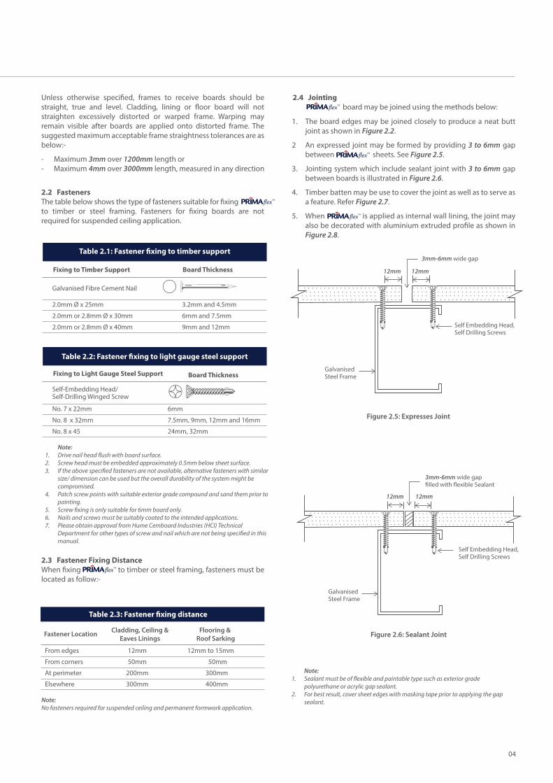
2.2 FastenersThe table below shows the type of fasteners suitable for �xing to timber or steel framing. Fasteners for �xing boards are not required for suspended ceiling application.
2.3 Fastener Fixing DistanceWhen �xing to timber or steel framing, fasteners must be located as follow:-
2.4 Jointing board may be joined using the methods below:
flex™
flex™
flex™
The board edges may be joined closely to produce a neat butt joint as shown in Figure 2.2.
An expressed joint may be formed by providing 3 to 6mm gap between sheets. See Figure 2.5.
Jointing system which include sealant joint with 3 to 6mm gap between boards is illustrated in Figure 2.6.
Timber batten may be use to cover the joint as well as to serve as a feature. Refer Figure 2.7.
When is applied as internal wall lining, the joint may also be decorated with aluminium extruded pro�le as shown in Figure 2.8.
1.
2
3.
4.
5.
flex™
flex™
2.0mm Ø x 25mm
2.0mm or 2.8mm Ø x 30mm
2.0mm or 2.8mm Ø x 40mm
3.2mm and 4.5mm
6mm and 7.5mm
9mm and 12mm
Board ThicknessFixing to Timber Support
Galvanised Fibre Cement Nail
Table 2.1: Fastener �xing to timber support
Table 2.3: Fastener �xing distance
From edges 12mm 12mm to 15mm
From corners 50mm 50mm
At perimeter 200mm 300mm
Elsewhere 300mm 400mm
Fastener Location Cladding, Ceiling &Eaves Linings
Flooring & Roof Sarking
Note:No fasteners required for suspended ceiling and permanent formwork application.
12mm 12mm
Self Embedding Head,Self Drilling Screws
3mm-6mm wide gap
Galvanised Steel Frame
Figure 2.5: Expresses Joint
12mm 12mm
Self Embedding Head,Self Drilling Screws
3mm-6mm wide gap �lled with �exible Sealant
Galvanised Steel Frame
Figure 2.6: Sealant Joint
Note:Sealant must be of �exible and paintable type such as exterior grade polyurethane or acrylic gap sealant.For best result, cover sheet edges with masking tape prior to applying the gap sealant.
1.
2.
No. 7 x 22mm
No. 8 x 32mm
No. 8 x 45
6mm
7.5mm, 9mm, 12mm and 16mm
24mm, 32mm
Board ThicknessFixing to Light Gauge Steel Support
Self-Embedding Head/ Self-Drilling Winged Screw
Table 2.2: Fastener �xing to light gauge steel support
Note:Drive nail head �ush with board surface.Screw head must be embedded approximately 0.5mm below sheet surface.If the above speci�ed fasteners are not available, alternative fasteners with similar size/ dimension can be used but the overall durability of the system might be compromised.Patch screw points with suitable exterior grade compound and sand them prior to painting.Screw �xing is only suitable for 6mm board only.Nails and screws must be suitably coated to the intended applications.Please obtain approval from Hume Cemboard Industries (HCI) Technical Department for other types of screw and nail which are not being speci�ed in this manual.
1. 2.3.
4.
5.6.7.
04

2.5 Finishes
2.5.1 PaintThis section is only applicable for applications requiring paint �nishes or coating systems. For best result, decorate board with a layer of suitable primer and a minimum two coats of quality water-based acrylic Paint. Coating should be of a vapour permeable type. Other types of coatings such as Polyurethane or Epoxy Paints are also suitable, but require special preparations. In all cases, coating manufacturer's recommendations should be adhered to. Upon installation, boards applied externally must be coated within 90 days. Do not leave board surface uncoated.
Ensure is dry and free from dust, grease or other contaminant before applying �nishing coat.
2.5.2 Other FinishesThis section is only applicable for lightweight �ooring application only. For dry area applications, ceramic tiles can be �xed directly onto board. For wet area applications, apply a layer of waterproo�ng membrane on before �xing the ceramic tiles. Use �exible Tile Adhesive, the Tile Adhesive normally comes in 2 parts, - ready mix cementitious cement and latex-based liquid solution. Refer to tile adhesive manufacturer for recommendation. Normal portland or composite cement / sand mortar is not recommended.
Board joints must be sanded if �exible materials such as vinyl tiles are to be applied onto board. All gaps and fastener points must be covered with cementitious plaster-based patching compound.
For general o�ce use, carpet is also a suitable for �ooring �nishing material.
2.5.3 Patching CompoundIf necessary, apply Patching Compound to cover screw points. Use cementitious plaster-based Patching Compound compatible with concrete products. For external application, exterior grade Patching Compound must be used.
When it is necessary to seal gaps between board joints, use �exible/ paintable Polyurethane (PU) Sealant or Modi�ed Silicone (MS) sealant. This Sealant should also be used to patch Screw Points when is used as wet area �ooring system. Always refer to sealant manufacturer for recommendations.
2.6 MaintenancePeriodic inspection and maintenance of the paint coating system must be performed as speci�ed by the paint manufacturer. All joints, sealant and wall surfaces must be checked for cracks to prevent the intrusion of water. Make good any defects in accordance with the systems outlined in this manual and good trade practice.
2.6.1 Precautionary Measures boards must always be kept dry prior to installation. When boards have been installed, ensure the construction is carried out until the installation of �nal roof covering material (i.e. metal roo�ng sheet). If roof section cannot be completed on the same day, installed boards must be protected against rain water or other source of moisture. Should incomplete roof section become wet, allow the components to dry before �xing the �nal roof covering material. Excessive moisture/ water trapped within the roof system will degrade its overall performance and durability.
flex™
flex™
flex™
flex™
flex™
flex™
flex™
12mm 12mm
Self Embedding Head,Self Drilling Screws
3mm wide gap
Galvanised Steel Frame
Figure 2.7: Timber Joint
12mm 12mm
Self Embedding Head,Self Drilling Screws
3mm wide gap
Pan Head Type 17 Screw
Galvanised Steel Frame
Aluminium Trimming with PVC Cover Strip
Figure 2.8: Aluminum Extrusion Joint
flex™ flex™
05
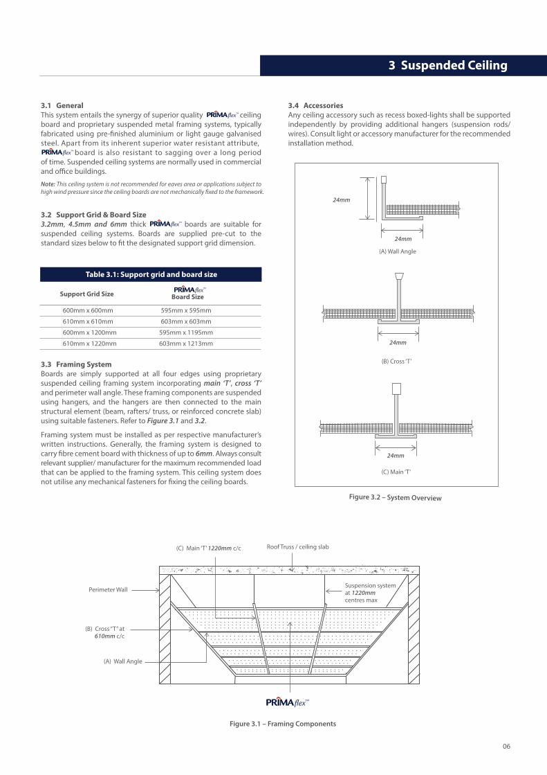
3.1 GeneralThis system entails the synergy of superior quality ceiling board and proprietary suspended metal framing systems, typically fabricated using pre-�nished aluminium or light gauge galvanised steel. Apart from its inherent superior water resistant attribute, board is also resistant to sagging over a long period of time. Suspended ceiling systems are normally used in commercial and o�ce buildings.
Note: This ceiling system is not recommended for eaves area or applications subject to high wind pressure since the ceiling boards are not mechanically �xed to the framework.
3.2 Support Grid & Board Size3.2mm, 4.5mm and 6mm thick boards are suitable for suspended ceiling systems. Boards are supplied pre-cut to the standard sizes below to �t the designated support grid dimension.
3.3 Framing SystemBoards are simply supported at all four edges using proprietary suspended ceiling framing system incorporating main ‘T’, cross ‘T’ and perimeter wall angle. These framing components are suspended using hangers, and the hangers are then connected to the main structural element (beam, rafters/ truss, or reinforced concrete slab) using suitable fasteners. Refer to Figure 3.1 and 3.2.
Framing system must be installed as per respective manufacturer’s written instructions. Generally, the framing system is designed to carry �bre cement board with thickness of up to 6mm. Always consult relevant supplier/ manufacturer for the maximum recommended load that can be applied to the framing system. This ceiling system does not utilise any mechanical fasteners for �xing the ceiling boards.
3 Suspended Ceiling
3.4 AccessoriesAny ceiling accessory such as recess boxed-lights shall be supported independently by providing additional hangers (suspension rods/ wires). Consult light or accessory manufacturer for the recommended installation method.
flex™
flex™
flex™
Table 3.1: Support grid and board size
600mm x 600mm 595mm x 595mm
610mm x 610mm 603mm x 603mm
600mm x 1200mm 595mm x 1195mm
610mm x 1220mm 603mm x 1213mm
Support Grid Size Board Size
Perimeter Wall
(A) Wall Angle
(B) Cross “T” at 610mm c/c
(C) Main ‘T’ 1220mm c/c
Suspension system at 1220mm centres max
Roof Truss / ceiling slab
Figure 3.1 – Framing Components
Figure 3.2 – System Overview
(A) Wall Angle
(B) Cross ‘T’
(C) Main ‘T’
24mm
24mm
24mm
24mm
flex™
flex™
06
4 Fixed Ceiling Eaves/ So�t Linings
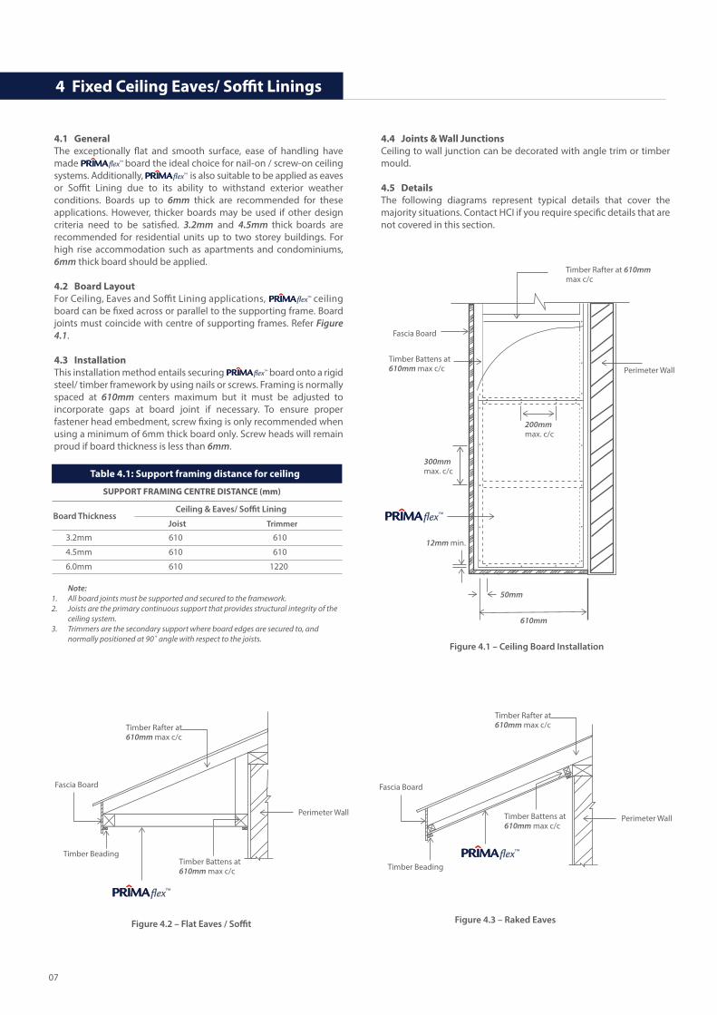
4.1 GeneralThe exceptionally �at and smooth surface, ease of handling have made board the ideal choice for nail-on / screw-on ceiling systems. Additionally, is also suitable to be applied as eaves or So�t Lining due to its ability to withstand exterior weather conditions. Boards up to 6mm thick are recommended for these applications. However, thicker boards may be used if other design criteria need to be satis�ed. 3.2mm and 4.5mm thick boards are recommended for residential units up to two storey buildings. For high rise accommodation such as apartments and condominiums, 6mm thick board should be applied.
4.2 Board LayoutFor Ceiling, Eaves and So�t Lining applications, ceiling board can be �xed across or parallel to the supporting frame. Board joints must coincide with centre of supporting frames. Refer Figure 4.1.
4.3 InstallationThis installation method entails securing board onto a rigid steel/ timber framework by using nails or screws. Framing is normally spaced at 610mm centers maximum but it must be adjusted to incorporate gaps at board joint if necessary. To ensure proper fastener head embedment, screw �xing is only recommended when using a minimum of 6mm thick board only. Screw heads will remain proud if board thickness is less than 6mm.
4.4 Joints & Wall JunctionsCeiling to wall junction can be decorated with angle trim or timber mould.
4.5 DetailsThe following diagrams represent typical details that cover the majority situations. Contact HCI if you require speci�c details that are not covered in this section.
flex™
flex™
flex™
flex™
Table 4.1: Support framing distance for ceiling
3.2mm 610 610
4.5mm 610 610
6.0mm 610 1220
Board ThicknessCeiling & Eaves/ So�t Lining
Joist Trimmer
SUPPORT FRAMING CENTRE DISTANCE (mm)
Timber Rafter at 610mm max c/c
Perimeter Wall
Figure 4.1 – Ceiling Board Installation
200mmmax. c/c
300mmmax. c/c
50mm
12mm min.
Timber Battens at610mm max c/c
Fascia Board
610mm
Figure 4.2 – Flat Eaves / So�t
Timber Rafter at 610mm max c/c
Timber Beading
Fascia Board
Perimeter Wall
Timber Battens at610mm max c/c
Figure 4.3 – Raked Eaves
Timber Rafter at 610mm max c/c
Timber Beading
Fascia Board
Perimeter WallTimber Battens at610mm max c/c
Note:All board joints must be supported and secured to the framework.Joists are the primary continuous support that provides structural integrity of the ceiling system.Trimmers are the secondary support where board edges are secured to, and normally positioned at 90˚ angle with respect to the joists.
1. 2.
3.
flex™
flex™
flex™
07
5 Wall & Gable End Cladding
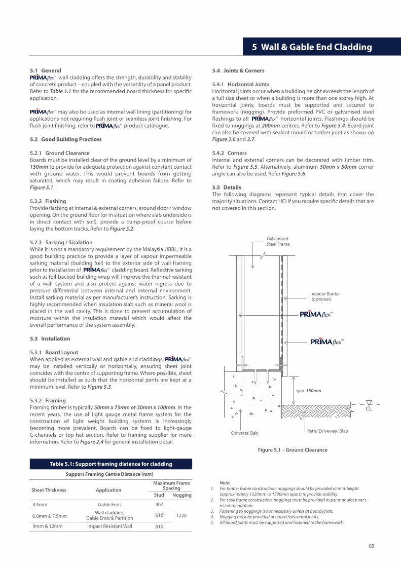
5.1 General wall cladding o�ers the strength, durability and stability of concrete product – coupled with the versatility of a panel product. Refer to Table 1.1 for the recommended board thickness for speci�c application.
may also be used as internal wall lining (partitioning) for applications not requiring �ush joint or seamless joint �nishing. For �ush joint �nishing, refer to product catalogue.
5.2 Good Building Practices
5.2.1 Ground ClearanceBoards must be installed clear of the ground level by a minimum of 150mm to provide for adequate protection against constant contact with ground water. This would prevent boards from getting saturated, which may result in coating adhesion failure. Refer to Figure 5.1.
5.2.2 FlashingProvide �ashing at internal & external corners, around door / window opening. On the ground �oor (or in situation where slab underside is in direct contact with soil), provide a damp-proof course before laying the bottom tracks. Refer to Figure 5.2.
5.2.3 Sarking / SisalationWhile it is not a mandatory requirement by the Malaysia UBBL, it is a good building practice to provide a layer of vapour impermeable sarking material (building foil) to the exterior side of wall framing prior to installation of cladding board. Re�ective sarking such as foil-backed building wrap will improve the thermal resistant of a wall system and also protect against water ingress due to pressure di�erential between internal and external environment. Install sarking material as per manufacturer’s instruction. Sarking is highly recommended when insulation slab such as mineral wool is placed in the wall cavity. This is done to prevent accumulation of moisture within the insulation material which would a�ect the overall performance of the system assembly.
5.3 Installation
5.3.1 Board Layout When applied as external wall and gable end claddings, may be installed vertically or horizontally, ensuring sheet joint coincides with the centre of supporting frame. Where possible, sheet should be installed as such that the horizontal joints are kept at a minimum level. Refer to Figure 5.3.
5.3.2 FramingFraming timber is typically 50mm x 75mm or 50mm x 100mm. In the recent years, the use of light gauge metal frame system for the construction of light weight building systems is increasingly becoming more prevalent. Boards can be �xed to light-gauge C-channels or top-hat section. Refer to framing supplier for more information. Refer to Figure 2.4 for general installation detail.
5.4 Joints & Corners
5.4.1 Horizontal JointsHorizontal joints occur when a building height exceeds the length of a full size sheet or when a building is more than one storey high. At horizontal joints, boards must be supported and secured to framework (nogging). Provide preformed PVC or galvanised steel �ashings to all horizontal joints. Flashings should be �xed to noggings at 200mm centres. Refer to Figure 5.4. Board joint can also be covered with sealant mould or timber joint as shown on Figure 2.6 and 2.7.
5.4.2 CornersInternal and external corners can be decorated with timber trim. Refer to Figure 5.5. Alternatively, aluminum 50mm x 50mm corner angle can also be used. Refer Figure 5.6.
5.5 DetailsThe following diagrams represent typical details that cover the majority situations. Contact HCI if you require speci�c details that are not covered in this section.
flex™
flex™
flex™
flex™
flex™
flex™
Figure 5.1 – Ground Clearance
Vapour Barrier(optional)
GalvanisedSteel Frame
Concrete Slab Path/ Driveway/ Slab
CL
gap 150mm
Table 5.1: Support framing distance for cladding
4.5mm Gable Ends
Wall cladding, Gable Ends & Partition
9mm & 12mm Impact Resistant Wall
Sheet Thickness Application
Support Framing Centre Distance (mm)
Maximum FrameSpacing
Stud Nogging
1220
407
610
610
Note:For timber frame construction, noggings should be provided at mid-height (approximately 1220mm to 1500mm apart) to provide stability.For steel frame construction, noggings must be provided as per manufacturer’s recommendation.Fastening to noggings is not necessary unless at board joints.Nogging must be provided at board horizontal joints.All board joints must be supported and fastened to the framework.
1.
2.
3.4.5.
6.0mm & 7.5mm
flex™
flex™
08
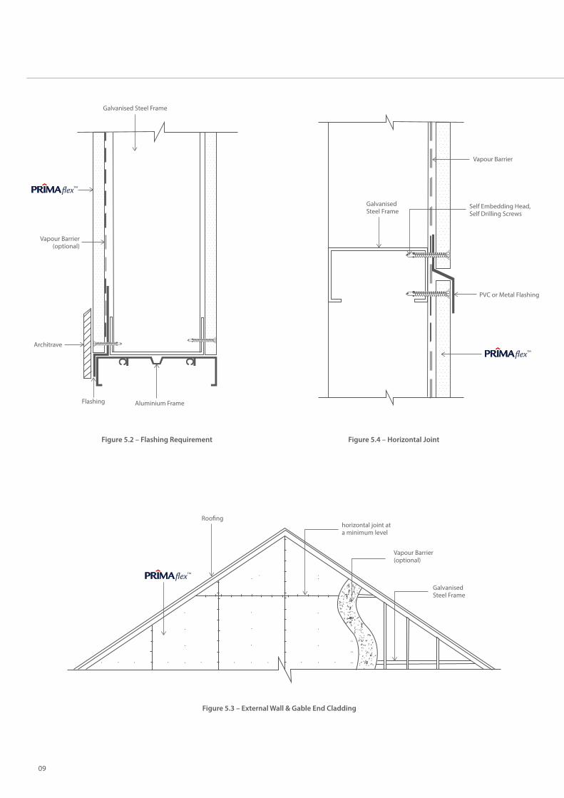
Figure 5.2 – Flashing Requirement Figure 5.4 – Horizontal Joint
Roo�nghorizontal joint ata minimum level
Vapour Barrier(optional)
GalvanisedSteel Frame
Figure 5.3 – External Wall & Gable End Cladding
Galvanised Steel Frame
Vapour Barrier
Self Embedding Head, Self Drilling Screws
PVC or Metal Flashing
Flashing Aluminium Frame
Vapour Barrier(optional)
Galvanised Steel Frame
Architrave
flex™
flex™
flex™
09
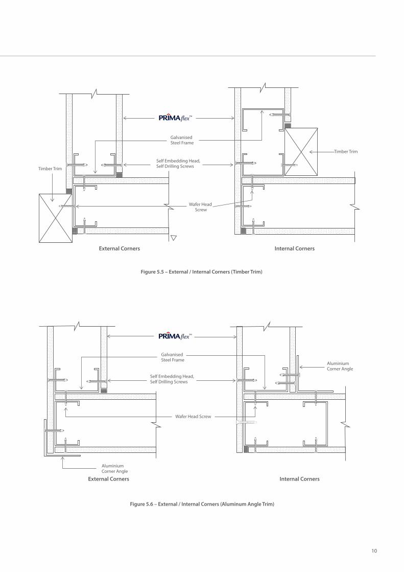
Figure 5.5 – External / Internal Corners (Timber Trim)
Figure 5.6 – External / Internal Corners (Aluminum Angle Trim)
Self Embedding Head, Self Drilling Screws
Wafer Head Screw
Timber Trim
Timber Trim
Galvanised Steel Frame
External Corners Internal Corners
Aluminium Corner Angle
Aluminium Corner Angle
Self Embedding Head, Self Drilling Screws
Wafer Head Screw
External Corners Internal Corners
Galvanised Steel Frame
flex™
flex™
10
6 Roof Sarking/ Underlay
6.1 General roof sarking / underlay are roof systems that incorporate the installation of board as an underlay for roo�ng sheets, supported by light gauge metal deck, purlins, rafters or roof trusses. The heat insulation property can further be improved by providing a layer of re�ective foil. The roof sarking / underlay provide practical solution when higher acoustic and thermal insulation properties are required. The thermal and sound insulation properties of the systems can be engineered to meet speci�c design criteria. For more information, contact our Technical Services Department.
Its unique combination of physical, mechanical and acoustic properties makes board an excellent choice for roof sarking applications particularly for residential, commercial and industrial buildings.
6.2 Design Consideration
6.2.1 Acoustic & Thermal InsulationGenerally, a minimum of 6mm thick board can be used. Sound and thermal insulation values of the composite roof systems can be improved by using thicker board (up to 16mm), multi-layer design, incorporation of insulation slab (i.e. rockwool). The sound and thermal insulation values of the proposed systems can be estimated using standard acoustic software and standard calculation method.
6.2.2 Typical Roof SystemsTypical composite roof systems incorporating board for residential and commercial building are shown in Figure 6.1 and 6.2. These systems are estimated to achieve the STC rating of 35 dB and 45dB respectively.
Note: The roof section details shown should be used as a guide only. The actual performance of the roof system is also highly dependent on other components, such as metal roo�ng, water proo�ng material or insulation materials. Thus, early engagement (at initial design stage) with roof system specialist and relevant consultant are highly recommended to ensure the targeted performance criteria are achievable.
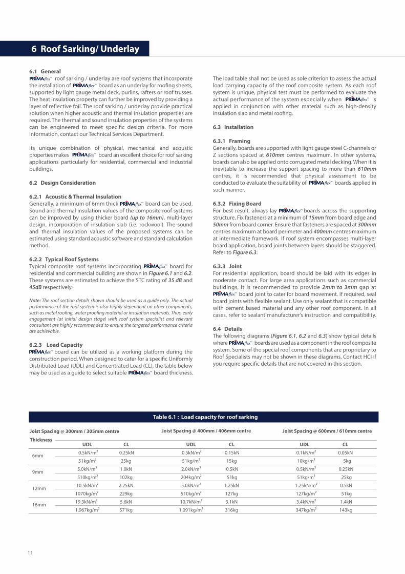
6.2.3 Load Capacity board can be utilized as a working platform during the construction period. When designed to cater for a speci�c Uniformly Distributed Load (UDL) and Concentrated Load (CL), the table below may be used as a guide to select suitable board thickness.
The load table shall not be used as sole criterion to assess the actual load carrying capacity of the roof composite system. As each roof system is unique, physical test must be performed to evaluate the actual performance of the system especially when is applied in conjunction with other material such as high-density insulation slab and metal roo�ng.
6.3 Installation
6.3.1 FramingGenerally, boards are supported with light gauge steel C-channels or Z sections spaced at 610mm centres maximum. In other systems, boards can also be applied onto corrugated metal decking. When it is inevitable to increase the support spacing to more than 610mm centres, it is recommended that physical assessment to be conducted to evaluate the suitability of boards applied in such manner.
6.3.2 Fixing BoardFor best result, always lay boards across the supporting structure. Fix fasteners at a minimum of 15mm from board edge and 50mm from board corner. Ensure that fasteners are spaced at 300mm centres maximum at board perimeter and 400mm centres maximum at intermediate framework. If roof system encompasses multi-layer board application, board joints between layers should be staggered. Refer to Figure 6.3.
6.3.3 JointFor residential application, board should be laid with its edges in moderate contact. For large area applications such as commercial buildings, it is recommended to provide 2mm to 3mm gap at board joint to cater for board movement. If required, seal board joints with �exible sealant. Use only sealant that is compatible with cement based material and any other roof component. In all cases, refer to sealant manufacturer’s instruction and compatibility.
6.4 DetailsThe following diagrams (Figure 6.1, 6.2 and 6.3) show typical details where boards are used as a component in the roof composite system. Some of the special roof components that are proprietary to Roof Specialists may not be shown in these diagrams. Contact HCI if you require speci�c details that are not covered in this section.
flex™
flex™
flex™
flex™
flex™
flex™
flex™
flex™
flex™
flex™
flex™
flex™
Table 6.1 : Load capacity for roof sarking
Joist Spacing @ 300mm / 305mm centre
6mm
9mm
12mm
16mm
Joist Spacing @ 400mm / 406mm centre Joist Spacing @ 600mm / 610mm centre
UDL CL UDL CL UDL CL
0.5kN/m² 0.25kN 0.5kN/m² 0.15kN 0.1kN/m² 0.05kN
51kg/m² 25kg 51kg/m² 15kg 10kg/m² 5kg
5.0kN/m² 1.0kN 2.0kN/m² 0.5kN 0.5kN/m² 0.25kN
510kg/m² 102kg 204kg/m² 51kg 51kg/m² 25kg
10.5kN/m² 2.25kN 5.0kN/m² 1.25kN 1.25kN/m² 0.5kN
1070kg/m² 229kg 510kg/m² 127kg 127kg/m² 51kg
19.3kN/m² 5.6kN 10.7kN/m² 3.1kN 3.4kN/m² 1.4kN
1,967kg/m² 571kg 1,091kg/m² 316kg 347kg/m² 143kg
Thickness
11
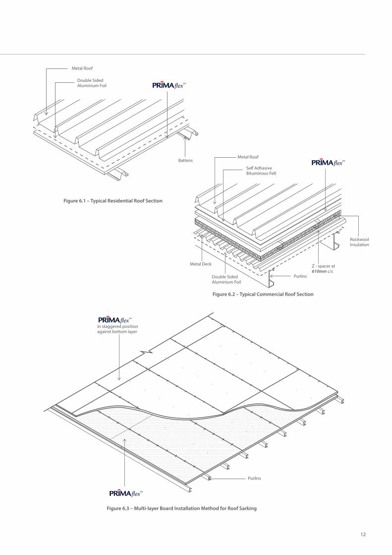
Figure 6.1 – Typical Residential Roof Section
Battens
Double Sided Aluminium Foil
Metal Roof
Figure 6.3 – Multi-layer Board Installation Method for Roof Sarking
in staggered positionagainst bottom layer
Purlins
Figure 6.2 – Typical Commercial Roof Section
Purlins
Self Adhesive Bituminous Felt
Double SidedAluminium Foil
Metal Deck
Metal Roof
RockwoolInsulation
Z - spacer at 610mm c/c
flex™
flex™
flex™
flex™
12
7 Flooring
7.1 General is suitable for the construction of lightweight platform / �oor system for residential, commercial as well as industrial buildings. The �oor system can be designed to meet speci�c load requirements based on the intended use. These load requirements are generally described in the local building code such as UBBL.
The system uses 12mm, 16mm, 24mm and 32mm thick fastened onto timber or steel framing system. These boards are manufactured in standard sizes of 1220mm x 2440mm.
7.2 Design Consideration
7.2.1 FramingFraming for �ooring can be constructed either of steel or timber, or a combination of both materials. The general requirements are describes as follows:-
The steel framing system is generally mild steel square / rectangular section or structural timber. Framing must have at least 45mm width in order to provide adequate fastener’s landing at �oorboard joint.
It is the responsibility of the structural engineer to ensure the framing system in which �ooring boards will be laid on will perform under the design load. Generally, framing structure is designed to cater for a maximum de�ection of L/250 of span under the service load. For �oor to be �nished with rigid material such as natural stone, please consult with HCI Technical Department.
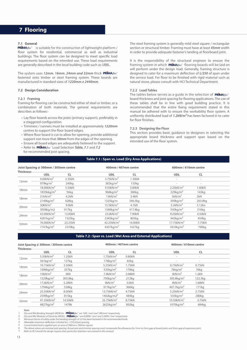
7.2.2 Load TablesThe tables below serves as a guide in the selection of board thickness and joist spacing for �ooring applications. The use of these tables shall be in line with good building practice. It is recommended that the entire �xing requirement stated in this manual be adhered with to ensure the workability �oor system. A uniformly distributed load of 1.2kN/m² has been factored in to cater for �oor �nishes.
7.2.3 Designing the FloorThis section provides basic guidance to designers in selecting the appropriate board thickness and support span based on the intended use of the �oor system.
flex™
• Lay �oor boards across the joists (primary support), preferably in a staggered con�guration.
• Trimmers / runners must be installed at approximately 1220mm centres to support the �oor board edges.
• Where �oor board is cut to allow for opening, provide additional support not more that 50mm from the edges of the opening.
• Ensure all board edges are adequately fastened to the support.• Refer to Load Selection Table, 7.1 and 7.2
for recommended joist spacing.
flex™
flex™
flex™
Table 7.1 : Span vs. Load (Dry Area Applications)
Joist Spacing @ 300mm / 305mm centre
12mm
16mm
18mm
20mm
24mm
32mm
400mm / 407mm centre 600mm / 610mm centre
UDL CL UDL CL UDL CL9.60kN/m² 2.35kN 3.75kN/m² 1.30kN - -979kg/m² 240kg 382kg/m² 133kg - -18.00kN/m² 5.50kN 9.50kN/m² 3.00kN 2.25kN/m² 1.40kN1835kkg/m² 56kg 968kg/m² 306kg 229kg/m² 143kg21kN/m² 4.2kN 13kN/m² 3.4kN 5kN/m² 2kN2140kg/m² 428kg 1325kg/m 346.5kg 509kg/m² 203.8kg30kN/m² 9.0kN 15.5kN/m² 4.1kN 5.2kN/m² 3.12kn3058kg/m2 917kg 1580kg/m² 417.8kg 530kg/m² 318kg42.00kN/m² 13.00kN 23.0kN/m² 7.90kN 9.25kN/m² 4.50kN4281kg/m² 1325kg 2345kg/m² 805kg 943kg/m² 459kg76.00kN/m² 23.25kN 42.25kN/m² 14.00kN 17.75kN/m² 7.75kN7747kg/m² 2370kg 4307kg/m² 1427kg 1810kg/m² 790kg
Thickness
Table 7.2 : Span vs. Load (Wet Area and External Applications)
Joist Spacing @ 300mm / 305mm centre
12mm
16mm
18mm
20mm
24mm
32mm
400mm / 407mm centre 600mm / 610mm centre
UDL CL UDL CL UDL CL5.50kN/m² 1.25kN 1.75kN/m² 0.80kN - -561kg/m² 127kg 178kg/m² 82kg - -10.75kN/m² 3.50kN 5.25kN/m² 1.75kN 0.75kN/m² 0.75kN1096kg/m² 357kg 535kg/m² 178kg 76kg/m² 76kg15kN/m² 3kN 7.8kN/m² 2.08kN 3kN/m² 1.2kN1529kg/m² 305.8kg 795kg/m² 212kg 305.8kg/m² 122.3kg17.6kN/m² 5.28kN 9kN/m² 3.6kN 4kN/m² 1.68kN1794kg/m² 538kg 917kg/m² 366kg 407.7kg/m² 171kg25.50kN/m² 8.00kN 13.75kN/m² 4.75kN 5.25kN/m² 2.75kN2599kg/m² 815kg 1402kg/m2² 484kg 535kg/m² 280kg47.35kN/m² 14.50kN 25.75kN/m² 8.75kN 10.50kN/m² 4.75kN4827kg/m² 1478k 2625kg/m² 892kg 1070kg/m² 484kg
Thickness
Note:Dry and Wet Bending Strength (MOR) for are 16N / mm2 and 10N/mm2 respectively.Dry and Wet Modulus of Elasticity (MOEs) are 8,000N / mm2 and 5,000N / mm2 respectively.Minimum factor of safety under the bending strength of 3.0 has been factored in the recommended loads.Allowable maximum de�ection is limited to L / 250 of joist spacing.Concentrated load is applied over an area of 300mm x 300mm square.The above values are nominal joist spacing. Actual joist and trimmer spacing must incorporate the allowance for 1mm to 2mm gap at board joints and 5mm gap at expansion joint.Refer to HCI should the design require other particular attention not covered in this manual.
1. 2.3.4.5.6.7.
flex™
flex™
13
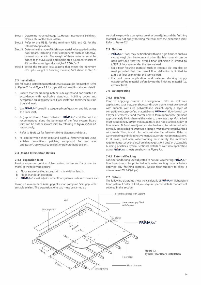
7.3 InstallationThe following installation method serves as a guide for installer. Refer to Figure 7.1 and Figure 7.2 for typical �oor board installation detail.
7.4 Joint & Intersection Details
7.4.1 Expansion JointProvide expansion joint at 6.1m centres maximum if any one (or more) of the following occurs:-
Provide a minimum of 6mm gap at expansion joint. Seal gap with suitable sealant. The expansion joint gap must be carried up
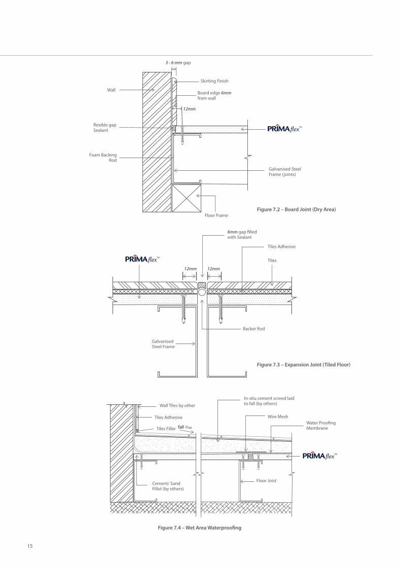
vertically to provide a complete break at board joint and the �nishing material. Do not apply �nishing material over the expansion joint. Refer to Figure 7.3.
7.5 Finishes
7.6 Waterproo�ng
7.6.1 Wet AreaPrior to applying ceramic / homogeneous tiles in wet area application, gaps between sheets and screw points must be covered with suitable wet area polyurethane sealant. Apply a layer of compatible waterproo�ng material onto �oor board. Lay a layer of cement / sand mortar bed to form appropriate gradient approximately 1% to channel the water to the waste trap. Mortar bed must be nominally 30mm minimum thick and not less than 20mm at �oor waste. At �oorboard joint, mortar bed must be reinforced with centrally embedded 150mm wide (gauge 1mm diameter) galvanised wire mesh. Then, install tiles with suitable tile adhesive. Refer to waterproo�ng and tile adhesive manufacturers for recommendations. In all cases, wet area waterproo�ng must satisfy the minimum requirements set by the local building regulations and/ or acceptable building practices. Typical sectional details of wet area application using sheets are shown in Figure 7.4.
7.6.2 External DeckingFor exterior decking use subjected to natural weathering, �oor boards must be protected with waterproo�ng material before applying any �nishing material. Adjust �oor support to allow a minimum of 2% fall (slope).
7.7 DetailsThe following diagrams show typical details of lightweight �oor system. Contact HCI if you require speci�c details that are not covered in this section.
Ensure that the framing system is designed and constructed in accordance with applicable standards, building codes and acceptable building practices. Floor joists and trimmers must be true and level.
Lay board in a staggered con�guration and laid across the �oor joist.
A gap of about 6mm between and the wall is recommended along the perimeter of the �oor system. Board joint can be butt or sealant joint by referring to Figure 2.2 or 2.6 respectively.
Refer to Table 2.3 for fasteners �xing distance and detail.
Fill gap between sheet joint and patch all fastener points using suitable cementitious patching compound. For wet area application, use wet area sealant or polyurethane sealant.
1.
2
3.
4.
5.
• �oor may be �nished with non-rigid �nished such as carpet, vinyl tiles, linoleum and other �exible materials can be used provided that the overall �oor de�ection is limited to L/250 of �oor span under the service load.
• Rigid �oor �nishing material such as ceramic tile can also be used provided that the overall �oor de�ection is limited to L/360 of �oor span under the service load.
• For wet area application and exterior decking, apply waterproo�ng material before laying the �nishing material (i.e. ceramic tiles).
Determine the actual usage (i.e. Houses, Institutional Buildings, O�ces, etc.) of the �oor system.Refer to the UBBL for the minimum UDL and CL for the intended application.Determine the type of �nishing material to be applied on the �oor board, including other components such as adhesive, cement mortar, e.t.c. The weight of these materials must be added to the UDL value obtained in step 2. Cement mortar of 25mm thickness typically weighs 0.57kN / m2.Select the suitable joist spacing that meets the minimum UDL (plus weight of �nishing material) & CL stated in Step 3.
Step: 1
Step: 2
Step: 3
Step: 4
Floor area to be tiled exceeds 6.1m in width or lengthFloor changes in direction sheet adjoins other �oor systems such as concrete slab.
a.b.c.
flex™
flex™
flex™flex™
flex™
flex™
flex™
flex™
Figure 7.1 – Typical Floor Board Installation
Wall
Skirting Finish
3 - 6mm gap �lled with Sealant
3mm - 6mm gap �lled with Sealant
Floor Joist
Joist Spacing
50mm
A
A
BB
Floor Trimmers
400mm
1220mm
300mm
12mm
flex™
14
�exible gapSealant
Foam BackingRod
Floor FrameFigure 7.2 – Board Joint (Dry Area)
Wall
Skirting Finish
Board edge 6mm from wall
12mm
Galvanised Steel Frame (joints)
GalvanisedSteel Frame
12mm12mm
Figure 7.3 – Expansion Joint (Tiled Floor)
6mm gap �lled with Sealant
Tiles Adhesive
Tiles
Backer Rod
Figure 7.4 – Wet Area Waterproo�ng
Floor Joist
Wall Tiles by other
Tiles Adhesive
Tiles Filler
Cement/ SandFillet (by others)
In-situ cement screed laidto fall (by others)
Wire Mesh Water Proo�ng Membranefall 1002
3 - 6 mm gap
flex™
flex™
flex™
15

8.1 General board serves as better alternative to conventional plywood formwork. It provides temporary support to which fresh concrete is poured to form reinforced concrete slab. It is recommended to be applied as permanent formwork in the construction of bridges, �yovers, �oor and approach slab for elevated MRT / LRT stations and many other usages.
The key advantages are:- • No propping is required • Faster than conventional formwork method • Eliminate / minimize labour for dismantling formwork • Suitable for bridge construction with limited excess • Will not rot & resistant to termite attack • Aesthetically pleasing
8.2 Design Consideration permanent formwork boards are supplied in a standard size of 1220mm x 2440mm. Boards can be cut at the project site to the required sizes to �t to the void (between beams) before steel bar reinforcement is tied and subsequently concrete is poured to form deck slab. Board must be kept dry prior to installation. Refer to the load table below for the appropriate span and concrete thickness.
8.3 Cutting & InstallationThe following describes a step-by-step instruction to a successfully application of permanent formwork. Any deviation from the recommended steps below may result board failure and personal injury.
8.4 DetailsThe following diagrams show typical details of permanent formwork application. Ensure particular attention with respect to the board cutting and requirement for waterproo�ng (if required) are adhered to. Contact HCI if you require speci�c details that are not covered in this section.
8 Permanent Formwork
flex™
flex™
Select that suitable board thickness based on the information in Table 8.1.
To obtain the permanent formwork width, add 80mm (allowance of 40mm support at each side) to the clear span.
Cut PFW board across the 2440mm side, forming a panel size of 1220mm x “Clear Span + 80mm”. Board must be cut as shown in Figure 8.1.
Position the cut panel centrally with its 1220mm edges running parallel to, and resting on the beam edges.
The remaining boards are laid into position with their edges in moderate contact with each other.
Install the reinforcing steel bar as per relevant construction drawings.
Pour fresh concrete to form the slab, ensuring no excessive accumulation of fresh concrete at the mid-span of board.
1.
2
3.
4.
5.
6.
7.flex™
flex™
Table 8.1: Loading table for Permanent Formwork
Recommended maximum clear span (mm)Boardthickness
Concrete thickness (mm)
400 500 600 700 800 900 1000 1100 1200
310 170 100 - - - - - -- 360 220 150 100 - - - -- 400 230 140 100 - - - -- - 300 185 115 - - - -- - - - 300 230 170 130 -- - - - 600 440 350 280 220
12mm16mm18mm20mm24mm32mm
Note:Clear span refers to the net edge-to-edge distance between beams. This is the area where board provides temporary support for the fresh concretethat forms the deck slab.A minimum factor of safety (in bending) of 2.0 has been incorporated in the design calculation.An allowance of 1.5kN/m2 of working load has been incorporated in the design calculation.Concrete density is assumed at 25kN/m3.Waterproo�ng material must be applied onto both surfaces and all board edges.Do not apply in area where will be ‘exposed to standing water’ or ‘continuously in contact with water’.Fresh concrete must be poured at the ‘beam’ area and progressively spread to other area to form the required ‘slab thickness’.Accumulation of ‘fresh concrete’ in excess of the recommended thickness, particularly at the mid-span of board may result in failure.
1.
2.
3.
4.5.6.
7.
8.
Figure 8.2 – Single Span Formwork System
40mm 40mm
Beam/Girder
Clear Span
Reinforcement Bar
Requires Water proo�ng on surface contact which Wet Concrete
Figure 8.1 – Board Cutting Method
ClearSpan
40mm40mm
cross cut
Wastages
board length = 2440mm
boar
d w
idth
= 1
220m
m
cross cut cross cut cross cut cross cut
flex™
16

9.1 Cutting sheets can be cut using common power assisted tools such as circular saw equipped with a diamond-tipped cutting blade. This operation must be carried out in a well-ventilated area only. Do not wet the sheet or the saw blade during cutting process. Power tools �tted with dust-extracting attachments are recommended. A dust mask and safety goggle must always be worn when cutting, drilling or grinding the sheet.
9.2 PenetrationsRound holes can be formed by drilling a series of smaller holes around the perimeter of the proposed opening, and subsequently tapping the waste piece out carefully. Trim the rough edges with rasp if required. Use suitable high-speed heavy duty drill bit. Rectangular or square openings can be achieved by using power assisted circular saw.
9.3 Handling & StorageAlways lift sheets vertically, on-edge and lengthwise. Store neatly on a �at surface supported evenly on bearers spaced at 600mm centres maximum, clear from ground to avoid damage and moisture ingress. Store under cover and ensure is dry prior to �xing. Never install damp or wet sheets as they are prone to shrinkage and subsequently may lead to joint failure. Damp or wet sheets must be allowed to dry to equilibrium moisture content before �xing.
9 Working Instructions
flex™
flex™
flex™
Figure 9: Handling
Figure 9.2: Notching and penetration
Figure 9.1: Score and Snap Method (left), Machine Cut (right)
17
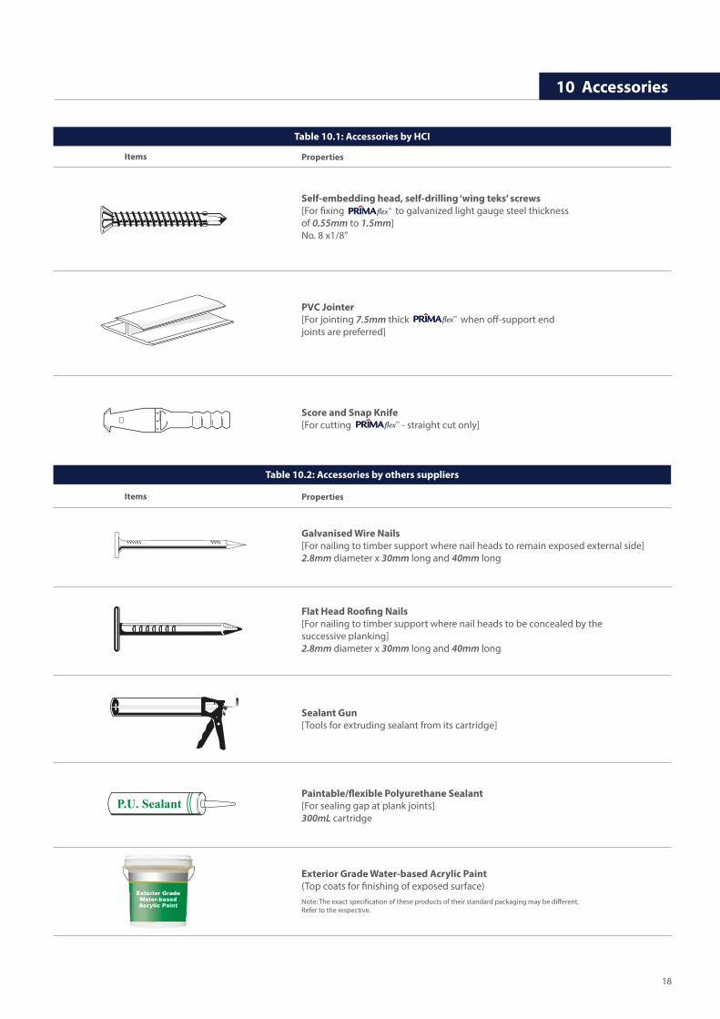
Score and Snap Knife[For cutting - straight cut only]
Self-embedding head, self-drilling ‘wing teks’ screws[For �xing to galvanized light gauge steel thickness of 0.55mm to 1.5mm]No. 8 x1/8”
10 Accessories
PVC Jointer[For jointing 7.5mm thick when o�-support end joints are preferred]
Galvanised Wire Nails[For nailing to timber support where nail heads to remain exposed external side]2.8mm diameter x 30mm long and 40mm long
Flat Head Roo�ng Nails[For nailing to timber support where nail heads to be concealed by the successive planking]2.8mm diameter x 30mm long and 40mm long
Sealant Gun[Tools for extruding sealant from its cartridge]
Paintable/�exible Polyurethane Sealant[For sealing gap at plank joints]300mL cartridge
Exterior Grade Water-based Acrylic Paint(Top coats for �nishing of exposed surface)Note: The exact specification of these products of their standard packaging may be different. Refer to the respective.
flex™
flex™
flex™
Table 10.1: Accessories by HCI
Table 10.2: Accessories by others suppliers
Items Properties
Items Properties
18
No. 12 Jalan Tandang, 46050 Petaling Jaya, Selangor, Malaysia.
Malaysia Sales Tel: + 603 7625 9999 Fax: +603 7625 7822 Email: [email protected] Sales Tel: + 603 7625 3880 Fax: +603 7625 3990 Email: [email protected]
www.primaf ibrecement.com
For more information, please contact us at:
50 Years Durability
50Years
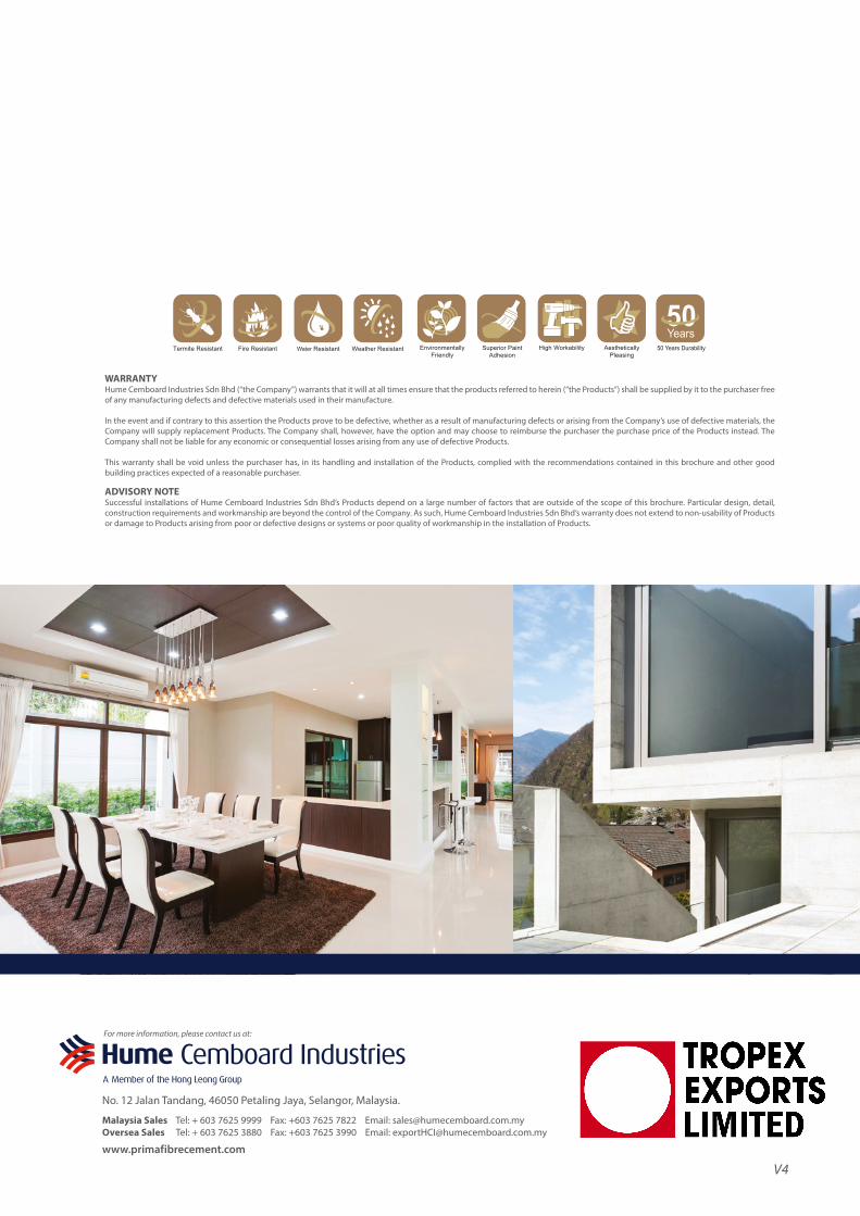
WARRANTYHume Cemboard Industries Sdn Bhd (“the Company”) warrants that it will at all times ensure that the products referred to herein (“the Products”) shall be supplied by it to the purchaser free of any manufacturing defects and defective materials used in their manufacture.
In the event and if contrary to this assertion the Products prove to be defective, whether as a result of manufacturing defects or arising from the Company’s use of defective materials, the Company will supply replacement Products. The Company shall, however, have the option and may choose to reimburse the purchaser the purchase price of the Products instead. The Company shall not be liable for any economic or consequential losses arising from any use of defective Products.
This warranty shall be void unless the purchaser has, in its handling and installation of the Products, complied with the recommendations contained in this brochure and other good building practices expected of a reasonable purchaser.
ADVISORY NOTESuccessful installations of Hume Cemboard Industries Sdn Bhd’s Products depend on a large number of factors that are outside of the scope of this brochure. Particular design, detail, construction requirements and workmanship are beyond the control of the Company. As such, Hume Cemboard Industries Sdn Bhd’s warranty does not extend to non-usability of Products or damage to Products arising from poor or defective designs or systems or poor quality of workmanship in the installation of Products.
V4