Embed Size (px)
Citation preview
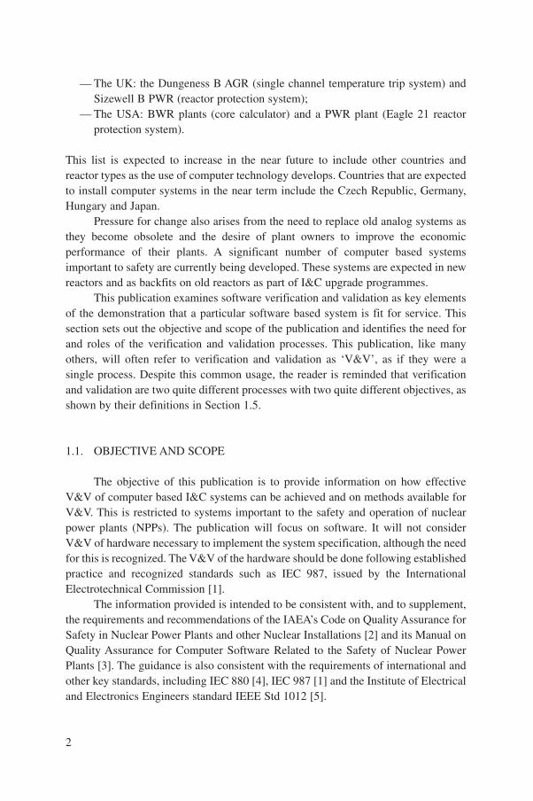
Verification and Validationof Software
Related to Nuclear Power PlantInstrumentation and Control
INTERNATIONAL ATOMIC ENERGY AGENCY, VIENNA, 1999
TTEECCHHNNIICCAALL RREEPPOORRTTSS SSEERRIIEESS NNoo..
Userrequirements
System requirementsspecification
Computer systemspecification
Software requirementsHardware requirementsIntegration requirements
Softwaredesign
Softwarecoding
Software design specificationModule specification
Detailed design
Softwaretest
Software testHardware integration
Hardware–software integration
Computer systemintegration
Integrated computersystem tests
Validation systemtests
Validation
Validation
Verification
Verification
Verification
Verification
Verification
384
Techn
ical Rep
orts S
eries No
.384V
erification
and
Valid
ation
of S
oftw
are Related
toN
uclear P
ow
er Plan
t Instru
men
tation
and
Co
ntro
l
ISBN 92–0–100799–XISSN 0074–1914
VERIFICATION AND VALIDATIONOF SOFTWARE RELATED TO
NUCLEAR POWER PLANTINSTRUMENTATION AND CONTROL
The following States are Members of the International Atomic Energy Agency:
AFGHANISTANALBANIAALGERIAARGENTINAARMENIAAUSTRALIAAUSTRIABANGLADESHBELARUSBELGIUMBOLIVIABOSNIA AND
HERZEGOVINABRAZILBULGARIABURKINA FASOCAMBODIACAMEROONCANADACHILECHINACOLOMBIACOSTA RICACOTE D’IVOIRECROATIACUBACYPRUSCZECH REPUBLICDEMOCRATIC REPUBLIC
OF THE CONGODENMARKDOMINICAN REPUBLICECUADOREGYPTEL SALVADORESTONIAETHIOPIAFINLANDFRANCEGABONGEORGIAGERMANYGHANAGREECEGUATEMALA
HAITIHOLY SEEHUNGARYICELANDINDIAINDONESIAIRAN, ISLAMIC REPUBLIC OF IRAQIRELANDISRAELITALYJAMAICAJAPANJORDANKAZAKHSTANKENYAKOREA, REPUBLIC OFKUWAITLATVIALEBANONLIBERIALIBYAN ARAB JAMAHIRIYALIECHTENSTEINLITHUANIALUXEMBOURGMADAGASCARMALAYSIAMALIMALTAMARSHALL ISLANDSMAURITIUSMEXICOMONACOMONGOLIAMOROCCOMYANMARNAMIBIANETHERLANDSNEW ZEALANDNICARAGUANIGERNIGERIANORWAYPAKISTANPANAMA
PARAGUAYPERUPHILIPPINESPOLANDPORTUGALQATARREPUBLIC OF MOLDOVAROMANIARUSSIAN FEDERATIONSAUDI ARABIASENEGALSIERRA LEONESINGAPORESLOVAKIASLOVENIASOUTH AFRICASPAINSRI LANKASUDANSWEDENSWITZERLANDSYRIAN ARAB REPUBLICTHAILANDTHE FORMER YUGOSLAV
REPUBLIC OF MACEDONIATUNISIATURKEYUGANDAUKRAINEUNITED ARAB EMIRATESUNITED KINGDOM OF
GREAT BRITAIN AND NORTHERN IRELAND
UNITED REPUBLICOF TANZANIA
UNITED STATESOF AMERICA
URUGUAYUZBEKISTANVENEZUELAVIET NAMYEMENYUGOSLAVIAZAMBIAZIMBABWE
The Agency’s Statute was approved on 23 October 1956 by the Conference on the Statute of theIAEA held at United Nations Headquarters, New York; it entered into force on 29 July 1957. TheHeadquarters of the Agency are situated in Vienna. Its principal objective is “to accelerate and enlarge thecontribution of atomic energy to peace, health and prosperity throughout the world’’.
© IAEA, 1999
Permission to reproduce or translate the information contained in this publication may beobtained by writing to the International Atomic Energy Agency, Wagramer Strasse 5, P.O. Box 100,A-1400 Vienna, Austria.
Printed by the IAEA in AustriaMay 1999
STI/DOC/010/384
VERIFICATION AND VALIDATIONOF SOFTWARE RELATED TO
NUCLEAR POWER PLANTINSTRUMENTATION AND CONTROL
TECHNICAL REPORTS SERIES No. 384
INTERNATIONAL ATOMIC ENERGY AGENCYVIENNA, 1999

VIC Library Cataloguing in Publication Data
Verification and validation of software related to nuclear power plantinstrumentation and control. — Vienna : International Atomic EnergyAgency, 1999.
p. ; 24 cm. — (Technical reports series, ISSN 0074–1914);no. 384)
STI/DOC/010/384ISBN 92–0–100799–XIncludes bibliographical references.
1. Computer software—Verification. 2. Nuclear power plants—Instruments. I. International Atomic Energy Agency. II. Series: Technicalreports series (International Atomic Energy Agency); 384.
VICL 99–00218
FOREWORD
The use of software based equipment and systems in nuclear power plants hasbeen growing in recent years, both as a result of the need to replace obsolete analogequipment and as a means of improving and ensuring satisfactory levels of plantavailability and safety. Software can now be found in safety applications (e.g.protection systems) and safety related applications (e.g. control systems), as well asin applications not important to safety (e.g. data logging). The use of computers innuclear power plants is not new. Computerized data collection and display systemshave been in operation for many years, and computers, often in the form ofprogrammable logic controllers, have been used widely in control applications.Computer based reactor protection and safety system actuation systems are lesscommon but have been introduced in many countries. These include Canada, France,the Republic of Korea, Sweden, the United Kingdom and the United States ofAmerica. This list is expected to lengthen in the near future to include countries suchas the Czech Republic, Germany, Hungary and Japan. It is computer based protectionsystems and their safety significance that have caused interest and concern regardingthe dependability of software and the justification of its integrity.
The nuclear industry does not face these issues alone. There have always beensignificant concerns about the introduction of software in industry and this appliesparticularly to safety applications. The nuclear industry is no different from othersectors except that its safety requirements are among the most demanding. Theprocesses of verification and validation, which are part of the development process,provide much of the evidence that the systems are suitable for use.
This publication has been produced in response to a recommendation of theIAEA International Working Group on Nuclear Power Plant Control andInstrumentation. The report has the objectives of providing practical guidance on themethods available for verification of the software and validation of computer basedsystems, and on how and when these methods can be effectively applied. Theintended readership consists of those who are in any way involved with thedevelopment, implementation, maintenance and use of software and computer basedinstrumentation and control systems in nuclear power plants. The report is intendedto be of use to designers, software producers, reviewers, verification and validationteams, assessors, plant operators and licensers of computer based systems.
Major contributions to the report were made by O. Andersson (Sweden),A.R. Ets (USA), E. Leret (France) and D.N. Wall (UK), who compiled the documentfrom contributions provided by members of the working team. The document wasfinalized by D.N. Wall and D. Welbourne (UK), together with A. Kossilov andV. Neboyan of the IAEA Division of Nuclear Power.
EDITORIAL NOTE
Although great care has been taken to maintain the accuracy of information containedin this publication, neither the IAEA nor its Member States assume any responsibility forconsequences which may arise from its use.
The mention of names of specific companies or products (whether or not indicated asregistered) does not imply any intention to infringe proprietary rights, nor should it beconstrued as an endorsement or recommendation on the part of the IAEA.
CONTENTS
1. INTRODUCTION . . . . . . . . . . . . . . . . . . . . . . . . . . . . . . . . . . . . . . . . . 1
1.1. Objective and scope . . . . . . . . . . . . . . . . . . . . . . . . . . . . . . . . . . . 21.2. Need for verification and validation . . . . . . . . . . . . . . . . . . . . . . . 31.3. Outline of the verification and validation process in the context
of this publication . . . . . . . . . . . . . . . . . . . . . . . . . . . . . . . . . . . . . 51.3.1. Verification of original requirements . . . . . . . . . . . . . . . . . 51.3.2. Verification of requirements specification . . . . . . . . . . . . . 61.3.3. V&V in development life cycle . . . . . . . . . . . . . . . . . . . . . 6
1.4. Organization and management of the verificationand validation process . . . . . . . . . . . . . . . . . . . . . . . . . . . . . . . . . . 8
1.5. Terminology . . . . . . . . . . . . . . . . . . . . . . . . . . . . . . . . . . . . . . . . . 10
2. SAFETY CLASSIFICATION AND TYPES OF SOFTWARE . . . . . . . . 11
2.1. Classification of systems . . . . . . . . . . . . . . . . . . . . . . . . . . . . . . . . 112.2. Types of software . . . . . . . . . . . . . . . . . . . . . . . . . . . . . . . . . . . . . 12
2.2.1. New software . . . . . . . . . . . . . . . . . . . . . . . . . . . . . . . . . . 152.2.2. Existing accessible software . . . . . . . . . . . . . . . . . . . . . . . 152.2.3. Existing proprietary software . . . . . . . . . . . . . . . . . . . . . . 212.2.4. Configurable software . . . . . . . . . . . . . . . . . . . . . . . . . . . . 22
2.3. Devices containing software . . . . . . . . . . . . . . . . . . . . . . . . . . . . . 232.4. Software tools . . . . . . . . . . . . . . . . . . . . . . . . . . . . . . . . . . . . . . . . 23
3. SOFTWARE RELATED ACTIVITIES AND DOCUMENTS . . . . . . . . . 24
3.1. Life cycle for new software . . . . . . . . . . . . . . . . . . . . . . . . . . . . . . 253.1.1. System requirements specification . . . . . . . . . . . . . . . . . . . 253.1.2. Computer system specification . . . . . . . . . . . . . . . . . . . . . 26
3.1.2.1. Software requirements . . . . . . . . . . . . . . . . . . . . . 263.1.2.2. Hardware requirements . . . . . . . . . . . . . . . . . . . . 273.1.2.3. Integration requirements . . . . . . . . . . . . . . . . . . . 27
3.1.3. System test plans . . . . . . . . . . . . . . . . . . . . . . . . . . . . . . . . 273.1.4. Software design . . . . . . . . . . . . . . . . . . . . . . . . . . . . . . . . . 28
3.1.4.1. Software system design . . . . . . . . . . . . . . . . . . . . 283.1.4.2. Detailed module specification . . . . . . . . . . . . . . . 283.1.4.3. Module design . . . . . . . . . . . . . . . . . . . . . . . . . . . 29
3.1.5. Coding . . . . . . . . . . . . . . . . . . . . . . . . . . . . . . . . . . . . . . . 29
3.1.6. Computer system integration . . . . . . . . . . . . . . . . . . . . . . . 293.1.6.1. Software tests . . . . . . . . . . . . . . . . . . . . . . . . . . . 293.1.6.2. Hardware integration . . . . . . . . . . . . . . . . . . . . . . 303.1.6.3. Hardware and software integration . . . . . . . . . . . . 30
3.1.7. Integrated computer system tests . . . . . . . . . . . . . . . . . . . . 303.1.8. Validation and commissioning tests . . . . . . . . . . . . . . . . . . 303.1.9. System handover . . . . . . . . . . . . . . . . . . . . . . . . . . . . . . . . 313.1.10. Operation, maintenance and modification . . . . . . . . . . . . . 31
3.2. Existing accessible software . . . . . . . . . . . . . . . . . . . . . . . . . . . . . 323.2.1. Mapping to new software life cycle . . . . . . . . . . . . . . . . . . 323.2.2. Identification of existing material . . . . . . . . . . . . . . . . . . . 32
3.3. Existing proprietary software . . . . . . . . . . . . . . . . . . . . . . . . . . . . 333.3.1. Mapping to new software life cycle . . . . . . . . . . . . . . . . . . 333.3.2. Identification of existing material . . . . . . . . . . . . . . . . . . . 34
3.4. Configurable software . . . . . . . . . . . . . . . . . . . . . . . . . . . . . . . . . . 343.4.1. Basic software . . . . . . . . . . . . . . . . . . . . . . . . . . . . . . . . . . 343.4.2. Configuration data . . . . . . . . . . . . . . . . . . . . . . . . . . . . . . . 34
4. VERIFICATION BY PHASE . . . . . . . . . . . . . . . . . . . . . . . . . . . . . . . . . 35
4.1. New software . . . . . . . . . . . . . . . . . . . . . . . . . . . . . . . . . . . . . . . . 364.1.1. Phase 1: Verification of system requirements
specification . . . . . . . . . . . . . . . . . . . . . . . . . . . . . . . . . . . 374.1.2. Phase 2: Verification of computer system
specification . . . . . . . . . . . . . . . . . . . . . . . . . . . . . . . . . . . 394.1.2.1. Verification of software requirements
specification . . . . . . . . . . . . . . . . . . . . . . . . . . . . 394.1.3. Verification of system test plans . . . . . . . . . . . . . . . . . . . . 404.1.4. Phase 3: Verification of software design
specification . . . . . . . . . . . . . . . . . . . . . . . . . . . . . . . . . . . 414.1.5. Phase 4: Verification of software coding . . . . . . . . . . . . . . 424.1.6. Phase 5: Verification of computer system integration . . . . . 454.1.7. Phase 6: Verification of integrated computer
system tests . . . . . . . . . . . . . . . . . . . . . . . . . . . . . . . . . . . . 484.1.8. Phase 7: Verification of validation and
commissioning tests . . . . . . . . . . . . . . . . . . . . . . . . . . . . . 494.1.9. Phase 8: Verification of system handover . . . . . . . . . . . . . . 504.1.10. Phase 9: Verification of operation, maintenance and
modification . . . . . . . . . . . . . . . . . . . . . . . . . . . . . . . . . . . 504.2. Existing accessible software . . . . . . . . . . . . . . . . . . . . . . . . . . . . . 524.3. Existing proprietary software . . . . . . . . . . . . . . . . . . . . . . . . . . . . 52

4.4. Configurable software . . . . . . . . . . . . . . . . . . . . . . . . . . . . . . . . . . 544.5. Data verification . . . . . . . . . . . . . . . . . . . . . . . . . . . . . . . . . . . . . . 544.6. Category B and C system verification . . . . . . . . . . . . . . . . . . . . . . 55
4.6.1. Category B and C requirements and design verification . . . 554.6.2. Category B and C implementation verification . . . . . . . . . 56
5. VALIDATION . . . . . . . . . . . . . . . . . . . . . . . . . . . . . . . . . . . . . . . . . . . . 57
5.1. New software . . . . . . . . . . . . . . . . . . . . . . . . . . . . . . . . . . . . . . . . 585.1.1. Validation process . . . . . . . . . . . . . . . . . . . . . . . . . . . . . . . 585.1.2. Output documents . . . . . . . . . . . . . . . . . . . . . . . . . . . . . . . 59
5.2. Existing accessible software . . . . . . . . . . . . . . . . . . . . . . . . . . . . . 605.3. Existing proprietary software . . . . . . . . . . . . . . . . . . . . . . . . . . . . 615.4. Configurable software . . . . . . . . . . . . . . . . . . . . . . . . . . . . . . . . . . 625.5. Data . . . . . . . . . . . . . . . . . . . . . . . . . . . . . . . . . . . . . . . . . . . . . . . 62
5.5.1. Data validation . . . . . . . . . . . . . . . . . . . . . . . . . . . . . . . . . 635.5.2. Validation of database management tools . . . . . . . . . . . . . 63
5.6. Validation of category B and C systems . . . . . . . . . . . . . . . . . . . . 64
6. LICENSING . . . . . . . . . . . . . . . . . . . . . . . . . . . . . . . . . . . . . . . . . . . . . 64
7. CONCLUSIONS . . . . . . . . . . . . . . . . . . . . . . . . . . . . . . . . . . . . . . . . . . 66
APPENDIX I: TECHNIQUES FOR VERIFICATION AND VALIDATION . . 71
I.1. Introduction . . . . . . . . . . . . . . . . . . . . . . . . . . . . . . . . . . . . . . . . . 71I.1.1. Scope . . . . . . . . . . . . . . . . . . . . . . . . . . . . . . . . . . . . . . . . 71I.1.2. Classification . . . . . . . . . . . . . . . . . . . . . . . . . . . . . . . . . . 71I.1.3. Format of survey . . . . . . . . . . . . . . . . . . . . . . . . . . . . . . . . 72
I.2. Techniques . . . . . . . . . . . . . . . . . . . . . . . . . . . . . . . . . . . . . . . . . . 72I.2.1. Review techniques . . . . . . . . . . . . . . . . . . . . . . . . . . . . . . 72
I.2.1.1. Inspection . . . . . . . . . . . . . . . . . . . . . . . . . . . . . . 72I.2.1.2. Walk-through . . . . . . . . . . . . . . . . . . . . . . . . . . . . 74I.2.1.3. Formalized descriptions . . . . . . . . . . . . . . . . . . . . 76I.2.1.4. Symbolic execution . . . . . . . . . . . . . . . . . . . . . . . 77I.2.1.5. Program proving . . . . . . . . . . . . . . . . . . . . . . . . . 78I.2.1.6. Prototype execution . . . . . . . . . . . . . . . . . . . . . . . 78I.2.1.7. Quality measurement by metrics . . . . . . . . . . . . . 79
I.2.2. Traceability analysis . . . . . . . . . . . . . . . . . . . . . . . . . . . . . 80I.2.3. Testing techniques . . . . . . . . . . . . . . . . . . . . . . . . . . . . . . . 81
I.2.3.1. White box testing . . . . . . . . . . . . . . . . . . . . . . . . . 81
I.2.3.2. Functional black box testing . . . . . . . . . . . . . . . . . 83I.2.3.3. Load testing . . . . . . . . . . . . . . . . . . . . . . . . . . . . . 86I.2.3.4. Statistical testing . . . . . . . . . . . . . . . . . . . . . . . . . 87I.2.3.5. Reliability growth models . . . . . . . . . . . . . . . . . . 88I.2.3.6. Timing analysis tests . . . . . . . . . . . . . . . . . . . . . . 89I.2.3.7. Periodic functional tests . . . . . . . . . . . . . . . . . . . . 90
I.2.4. Safety analysis techniques . . . . . . . . . . . . . . . . . . . . . . . . . 91I.2.4.1. Failure mode effect and criticality analysis . . . . . . 91I.2.4.2. Fault tree analysis . . . . . . . . . . . . . . . . . . . . . . . . 92
APPENDIX II: SINGLE FAILURE CRITERION . . . . . . . . . . . . . . . . . . . . . 93
II.1. Introduction . . . . . . . . . . . . . . . . . . . . . . . . . . . . . . . . . . . . . . . . . 93II.2. Application of single failure criterion to systems
important to safety . . . . . . . . . . . . . . . . . . . . . . . . . . . . . . . . . . . . 94
APPENDIX III: EXPERIENCE . . . . . . . . . . . . . . . . . . . . . . . . . . . . . . . . . . . 96
III.1. Canada . . . . . . . . . . . . . . . . . . . . . . . . . . . . . . . . . . . . . . . . . . . . . 96III.1.1. Standards and practices . . . . . . . . . . . . . . . . . . . . . . . . . . . 97III.1.2. Pickering digital trip meter (Ontario Hydro) . . . . . . . . . . . 98III.1.3. Wolsong 2, 3 and 4 shutdown systems SDS1
and SDS2 (AECL) . . . . . . . . . . . . . . . . . . . . . . . . . . . . . . 98III.1.4. Future development . . . . . . . . . . . . . . . . . . . . . . . . . . . . . . 99
III.2. France . . . . . . . . . . . . . . . . . . . . . . . . . . . . . . . . . . . . . . . . . . . . . 100III.2.1. Standards and practices . . . . . . . . . . . . . . . . . . . . . . . . . . . 100III.2.2. Systems in use . . . . . . . . . . . . . . . . . . . . . . . . . . . . . . . . . 100
III.2.2.1. 1300 MW(e) series . . . . . . . . . . . . . . . . . . . . . . 100III.2.2.2. N4 series . . . . . . . . . . . . . . . . . . . . . . . . . . . . . . 100III.2.2.3. Verification and validation of SPIN software . . . 101III.2.2.4. Verification and validation of PLCs for 2E
functions (N4 series) . . . . . . . . . . . . . . . . . . . . . 102III.2.2.5. Verification and validation of software supporting
main control system (N4 series) . . . . . . . . . . . . 103III.2.2.6. Verification and validation of data . . . . . . . . . . . 104
III.2.3. Current and future states . . . . . . . . . . . . . . . . . . . . . . . . . . 105III.3. Germany . . . . . . . . . . . . . . . . . . . . . . . . . . . . . . . . . . . . . . . . . . . . 105III.4. Hungary . . . . . . . . . . . . . . . . . . . . . . . . . . . . . . . . . . . . . . . . . . . . 107
III.4.1. Systems in use . . . . . . . . . . . . . . . . . . . . . . . . . . . . . . . . . 107III.4.2. Future needs . . . . . . . . . . . . . . . . . . . . . . . . . . . . . . . . . . . 108
III.5. Russian Federation . . . . . . . . . . . . . . . . . . . . . . . . . . . . . . . . . . . . 109
III.5.1. Standards and practices . . . . . . . . . . . . . . . . . . . . . . . . . . . 109III.5.2. Systems in use . . . . . . . . . . . . . . . . . . . . . . . . . . . . . . . . . 109III.5.3. Current and future states . . . . . . . . . . . . . . . . . . . . . . . . . . 110
III.6. Sweden . . . . . . . . . . . . . . . . . . . . . . . . . . . . . . . . . . . . . . . . . . . . . 110III.6.1. Standards and practices . . . . . . . . . . . . . . . . . . . . . . . . . . . 110III.6.2. Systems in use: Forsmark 1 and 2 . . . . . . . . . . . . . . . . . . . 111
III.7. United Kingdom . . . . . . . . . . . . . . . . . . . . . . . . . . . . . . . . . . . . . . 111III.7.1. Standards and practices . . . . . . . . . . . . . . . . . . . . . . . . . . . 111III.7.2. Systems in use . . . . . . . . . . . . . . . . . . . . . . . . . . . . . . . . . 112
III.7.2.1. Dungeness B single channel trip system . . . . . . 112III.7.2.2. Sizewell B primary protection system . . . . . . . . 112
III.7.3. Current and future states . . . . . . . . . . . . . . . . . . . . . . . . . . 116III.8. United States of America . . . . . . . . . . . . . . . . . . . . . . . . . . . . . . . 116
III.8.1. Standards and practices . . . . . . . . . . . . . . . . . . . . . . . . . . . 117III.8.2. Systems in use . . . . . . . . . . . . . . . . . . . . . . . . . . . . . . . . . 118III.8.3. Current and future states . . . . . . . . . . . . . . . . . . . . . . . . . . 118
REFERENCES . . . . . . . . . . . . . . . . . . . . . . . . . . . . . . . . . . . . . . . . . . . . . . . . 121CONTRIBUTORS TO DRAFTING AND REVIEW . . . . . . . . . . . . . . . . . . . . 125

1
1. INTRODUCTION
Computer equipment and information processing technology have been quicklytaken up and exploited by instrumentation and control (I&C) engineers in the processindustries to improve and ensure satisfactory levels of plant performance. Systemsusing computers and related technology were initially installed for functions whichwere needed for plant operation, but which were not important to safety. Computerswere widely installed in systems for data collection, information display and datalogging, and also in systems providing important control functions. They were ofteneasily accepted at plants by the users. Their introduction for protection purposesrapidly followed their use in the aforementioned roles in most industrial sectors.
The introduction of software to perform critical functions in industry hasalways caused concern. The introduction of software based systems has led to welldocumented difficulties in several industrial sectors, for example the controversyassociated with aircraft with multiplexed (fly by wire) controls. The nuclear industryis no different from any other sector except that the safety requirements are amongthe most demanding. The introduction of computer based systems in the nuclearsector has not been easy, since new methods and criteria have been needed to assessand judge their safety and integrity. For example, it has resulted in the introduction ofa special procedure by the licensing body in the United Kingdom, the NuclearInstallations Inspectorate, and software was declared by the Nuclear RegulatoryCommission in the United States of America as posing an “unresolved safety issue”(at the time of preparation of this publication).
Nuclear plants followed the trend of computerization of functions. This wasinitially driven by economic pressures such as the cost of the equipment required fordata collection. During this time computer based systems were restricted toapplications with low safety significance. This was done very deliberately, to avoidproblems of demonstrating software integrity. This restriction was steadily eroded aspressure for enhanced safety, functionality and reliability increased. Computersstarted to appear with safety roles, for example the core calculator in some BWRs inthe USA. This position has changed still further in the last few years with computerbased systems being introduced with a primary role in nuclear safety. There arealready systems for reactor protection in use in:
— Canada: the Point Lepreau, Darlington and Gentilly 2 CANDU plants (reactorprotection system);
— France: the 1300 MW(e) series of PWR plants (SPIN 1 reactor protectionsystem);
— The Republic of Korea: the Wolsong 1 CANDU power unit (reactor protectionsystem);
— Sweden: the Forsmark BWR plant (neutron flux measurement and protection);
— The UK: the Dungeness B AGR (single channel temperature trip system) andSizewell B PWR (reactor protection system);
— The USA: BWR plants (core calculator) and a PWR plant (Eagle 21 reactorprotection system).
This list is expected to increase in the near future to include other countries andreactor types as the use of computer technology develops. Countries that are expectedto install computer systems in the near term include the Czech Republic, Germany,Hungary and Japan.
Pressure for change also arises from the need to replace old analog systems asthey become obsolete and the desire of plant owners to improve the economicperformance of their plants. A significant number of computer based systemsimportant to safety are currently being developed. These systems are expected in newreactors and as backfits on old reactors as part of I&C upgrade programmes.
This publication examines software verification and validation as key elementsof the demonstration that a particular software based system is fit for service. Thissection sets out the objective and scope of the publication and identifies the need forand roles of the verification and validation processes. This publication, like manyothers, will often refer to verification and validation as ‘V&V’, as if they were asingle process. Despite this common usage, the reader is reminded that verificationand validation are two quite different processes with two quite different objectives, asshown by their definitions in Section 1.5.
1.1. OBJECTIVE AND SCOPE
The objective of this publication is to provide information on how effectiveV&V of computer based I&C systems can be achieved and on methods available forV&V. This is restricted to systems important to the safety and operation of nuclearpower plants (NPPs). The publication will focus on software. It will not considerV&V of hardware necessary to implement the system specification, although the needfor this is recognized. The V&V of the hardware should be done following establishedpractice and recognized standards such as IEC 987, issued by the InternationalElectrotechnical Commission [1].
The information provided is intended to be consistent with, and to supplement,the requirements and recommendations of the IAEA’s Code on Quality Assurance forSafety in Nuclear Power Plants and other Nuclear Installations [2] and its Manual onQuality Assurance for Computer Software Related to the Safety of Nuclear PowerPlants [3]. The guidance is also consistent with the requirements of international andother key standards, including IEC 880 [4], IEC 987 [1] and the Institute of Electricaland Electronics Engineers standard IEEE Std 1012 [5].
2

This report uses the categories A, B and C, ranking importance to safety offunctions, systems and equipment, as defined in IEC 1226 [6]. It assumes theexistence of a system requirements specification that is complete, correct, consistentand unambiguous at the beginning of the development process. It assumes also thatthe software is developed following a conventional life cycle, consisting of a series ofdefined, planned steps. The means of verifying the inputs to and outputs from each ofthese steps are then discussed. The methods for performing validation of the productare discussed similarly. The relationship to licensing is discussed and conclusions aregiven.
Techniques for V&V are reviewed in Appendix I. The single failure criterion isdiscussed in Appendix II. The experience of several countries is summarized inAppendix III. Tables show the inputs, tasks and outputs of each V&V step, withrecommendations on techniques, for each category of safety importance.
The publication is intended for use as a reference when establishing the meansof verifying and validating software. The information is not prescriptive in nature, bycontrast to the requirements of a standard. It is expected that this publication will beused to produce approaches to V&V processes. The approaches should be consistentwith the production method being used and make the best use of staff and toolsavailable, while taking due account of the prevailing regulatory conditions. It is notintended to identify a set of defined V&V processes which should be completed inorder for the system to be licensable.
This publication was developed primarily to assist suppliers, users andregulators in the development, installation, acceptance and licensing of computerbased systems important to safety. The techniques can and ought to be applied toplant control and other computer based systems. The user of the publication mayselect and apply those recommendations that are applicable to the development routechosen for a given project, in the context of the safety role of the product. Justificationof the approach adopted would normally be required by the quality plan of thedevelopment process.
The key references which form the basis of this publication are Refs [3, 4, 6–8].
1.2. NEED FOR VERIFICATION AND VALIDATION
There is a possibility that the designers and implementers of a computer basedsystem will make errors, and that the errors will result in undetected faults in thesystem. The system may then be installed with faults in it. This could clearly result indangerous failures. The detection of errors is therefore important of itself. Owingpartly to anecdotal stories and partly to some poor experience, the public perceptionof software systems is that they are likely to fail. Public confidence requires the safety
3

regulator to have very high assurance, supported by clear evidence, that errors havebeen detected suitably.
The failures that can result from these faults make it necessary to apply activemeasures in a systematic manner to find and correct errors. Current practice forcomputer based systems places a heavy dependence on V&V to detect errors. TheV&V processes provide assurance that the specified functional and reliabilityrequirements of the system are met.
Hardware development and V&V processes are generally considered to besufficiently mature to detect systematic errors effectively. If the systematic error rateis very low, the failure rate of the final system can be bounded by the random failurerate of the hardware. This must be questioned if the complexity of the hardwareincreases or when novel technology is used. For example, application specificintegrated circuits, and similar devices, involve many thousands of interconnectedlogic gates on a single chip. The reliability of such devices could be vulnerable tounrevealed errors in the design or production processes. The reliability could theninclude a significant systematic fault probability, and would not be limited by therandom failure probability alone.
The present approach to software reliability is similar to that described above.Software faults are due to human error, and the resulting failures are systematic incharacter. The approach concentrates on methods of demonstrating that no errorswere made in implementing the requirements. The aim is to show with highconfidence that very few software faults exist, such that the systematic failure rate isacceptably low. If this is shown, then the assumption is made that the systemreliability is limited by the hardware random failure rate. The justification of thisassumption places a major dependence on the integrity of the development and V&Vprocesses. These processes provide the evidence to enable the assumption to be madeand justified. They therefore provide a route to qualification of the system for anapplication important to safety.
To be effective, V&V should be carried out in conjunction with a structuredsoftware development process. The V&V must consider the context of the systemapplication. This publication considers the production of new software following thesoftware life cycle given in IEC 880, but recognizes that the new software approachmay not always be applicable. Existing, predeveloped software may be reused toimplement new systems [4]. Indeed, software reuse is expected to become a frequentfeature of new systems, and to bring reliability and cost advantages when it iscorrectly adopted.
When developing new software, faults can be introduced at every stage of thedevelopment process, from specification to system integration. The first element ofverification is to find and correct errors as early as possible in the life cycle. This isdone by performing verification when the development team considers that it hassuccessfully completed each phase. The second element of verification is to provide
4
assurance that all software faults which could degrade system performance have beenremoved. In addition, for safety systems, each verification step should identify thatthe system requirements are satisfied.
Validation provides demonstration and assurance that the software and thesystem meet all specified requirements. Validation thus provides checks of systemfunctionality against system requirements. It aims to show that all faults which coulddegrade system performance have been removed before the system is operated.
To be successful, the V&V processes must fulfil these functions. This requiresan orderly, planned approach to V&V. Successful V&V will result in the reduction ofthe number of software faults to a tolerable minimum. Therefore, the number offailures in service should be acceptably low. Particular attention must be given to theoutput products of the V&V processes to ensure that they can be used by others, suchas a reviewer or a licenser. There must be clear documentary evidence to demonstrateto an independent body that there is high assurance that the in-service performancewill be acceptable.
1.3. OUTLINE OF THE VERIFICATION AND VALIDATION PROCESSIN THE CONTEXT OF THIS PUBLICATION
Verification and validation are part of the development process and arecontrasted in this report with the quality assurance (QA) process. Verification andvalidation are means by which the product is checked, and by which its performanceis demonstrated and assured to be a correct interpretation of the requirements. Acontinuous process of V&V must be actively applied throughout the softwaredevelopment cycle. V&V includes a strong element of checking, and leads toremedial action. By contrast, QA ensures that a suitable management process hasbeen specified, that the development process conforms to the requirements of basicstandards and that the process specified is followed. Applicable standards may be ISO9000-3, issued by the International Organization for Standardization, and IEEEStd 730 [9, 10]. Quality control (QC) is performed to check that the specifiedsoftware development methods and process in the QA plan have been correctlyfollowed.
1.3.1. Verification of original requirements
A correct form of the system requirements specification is needed to start thedevelopment and V&V. Experience indicates that some requirement errors will exist.All system design documentation should be consistent with the stated requirements.If the requirements specification is incorrect, subsequent parts of the developmentmay contain faults that verification alone may be unable to identify.
5
A safety system requirements specification will have been produced byreference to the reactor safety analysis during the plant design and by considerationof plant and reactor performance limits. The preparation of the requirements forclosed loop control systems may involve extensive modelling of the reactor and plantdynamics to derive the algorithms for control and to demonstrate their stability. Thepreparation of the requirements for open loop control of switchgear, valves andmotors will involve identification and grouping of the logic functions of each controlswitch or control function. These specifications should provide sufficient detail toallow the development process to take place without any risk of misinterpretation.
The computer based implementation of these functional requirements willtherefore have involved system design processes, which are normally subject to reviewand design control methods. This implies that the requirements specification has beenverified against the safety and performance requirements of the plant. These processesare very important to the system integrity, but outside the scope of this publication.
1.3.2. Verification of requirements specification
The requirements specification may have two types of error: requirementsincorrect of themselves but correctly implemented and errors of implementation ofcorrect requirements. A well designed system acceptance test should find faultsarising from errors in the functional requirements, i.e. the validation tests foracceptance should not be based solely on the written requirements specification butshould attempt to test from first principles.
If the final product has inconsistencies with or omissions from the systemrequirements specification, the position is quite different, and verification can detectthe errors. The use of requirement trace methods in development and particularly inverification should, if correctly established and followed, identify inconsistencies andomissions. Verification should also find and account for necessary additionalfunctions, needed for engineering and maintenance reasons, which are not defined inthe system requirements specification.
The verified requirements specification can then serve as the initial input to theV&V processes discussed here. It is recognized that in practice this is not always thecase, and the requirements may be under some development themselves.Consequently, there is a need for a procedure to ensure the resolution of any problemsidentified with the system requirements specification, particularly as experienceshows that this is the source of many errors.
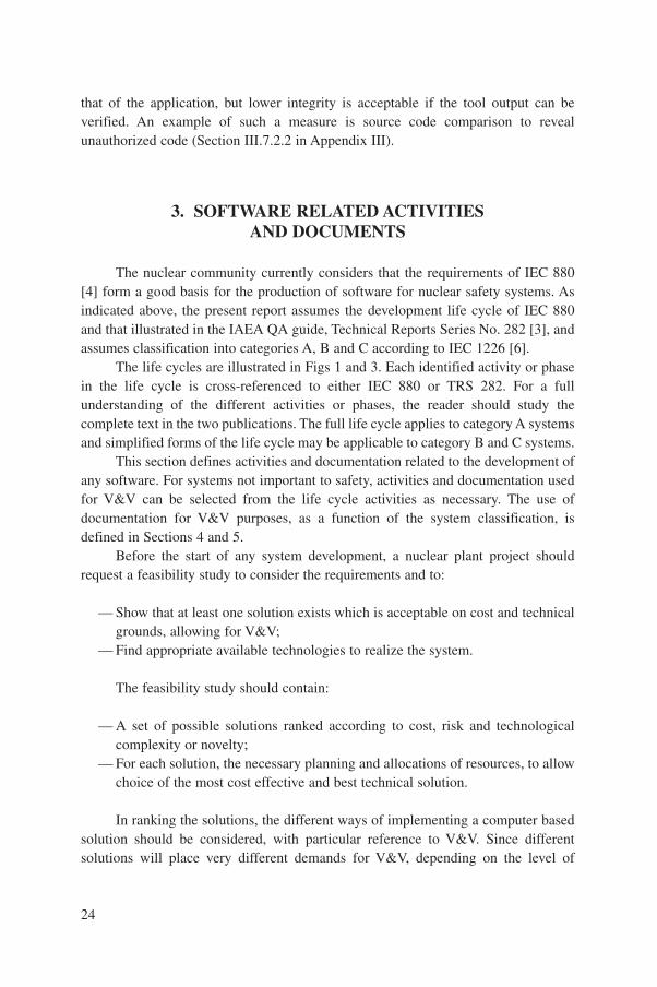
1.3.3. V&V in development life cycle
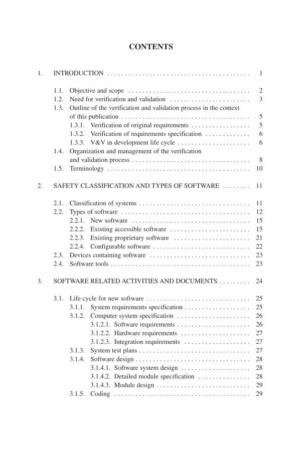
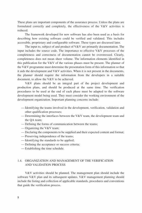
For new software this publication specifically refers to the V&V of thedevelopment process phases of IEC 880 [4], described in detail in Section 3.1. These
6
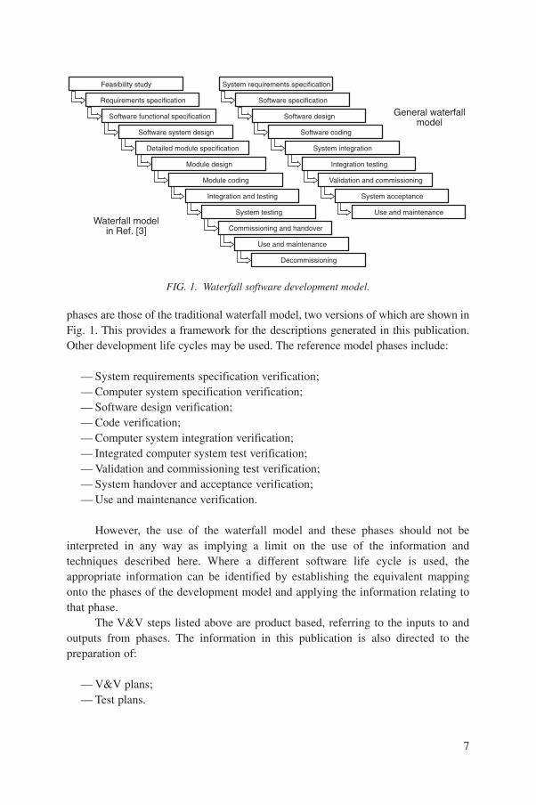
phases are those of the traditional waterfall model, two versions of which are shown inFig. 1. This provides a framework for the descriptions generated in this publication.Other development life cycles may be used. The reference model phases include:
— System requirements specification verification;— Computer system specification verification;— Software design verification;— Code verification;— Computer system integration verification;— Integrated computer system test verification;— Validation and commissioning test verification;— System handover and acceptance verification;— Use and maintenance verification.
However, the use of the waterfall model and these phases should not beinterpreted in any way as implying a limit on the use of the information andtechniques described here. Where a different software life cycle is used, theappropriate information can be identified by establishing the equivalent mappingonto the phases of the development model and applying the information relating tothat phase.
The V&V steps listed above are product based, referring to the inputs to andoutputs from phases. The information in this publication is also directed to thepreparation of:
— V&V plans;— Test plans.
7
FIG. 1. Waterfall software development model.
Feasibility study
Requirements specification
Software functional specification
Software system design
Detailed module specification
Module design
Module coding
Integration and testing
System testing
Commissioning and handover
Use and maintenance
Decommissioning
System requirements specification
Software specification
Software design
Software coding
System integration
Integration testing
Validation and commissioning
System acceptance
Use and maintenance
General waterfallmodel
Waterfall modelin Ref. [3]
These plans are important components of the assurance process. Unless the plans areformulated correctly and completely, the effectiveness of the V&V activities isreduced.
The framework developed for new software has also been used as a basis fordescribing how existing software could be verified and validated. This includesaccessible, proprietary and configurable software. These types are discussed later.
The input to, subject of and product of V&V are primarily documentation. Theinput includes the source code. The importance to effective V&V processes of thecompleteness and correctness of documentation cannot be overstressed. Clearly,completeness does not mean sheer volume. The information elements identified inthis publication for the V&V of the various phases must be present. The planner ofthe V&V programme must determine the presentation form of this information so thatit aids the development and V&V activities. When it is not present in the documents,the planner should require the information from the developers in a suitabledocument, to allow the V&V to be achieved.
V&V plans should be an integral part of the project development andproduction plans, and should be produced at the same time. The verificationprocedures to be used at the end of each phase must be adapted to the softwaredevelopment model being used. They must consider the working environment of thedevelopment organization. Important planning concerns include:
— Identifying the teams involved in the development, verification, validation andother qualification processes;
— Determining the interfaces between the V&V team, the development team andthe QA team;
— Defining the forms of communication between the teams;— Organizing the V&V team;— Declaring the components to be supplied and their expected content and format;— Preserving independence of the teams;— Identifying the standards to be applied;— Defining the acceptance or success criteria;— Establishing the time schedule.
1.4. ORGANIZATION AND MANAGEMENT OF THE VERIFICATIONAND VALIDATION PROCESS
V&V activities should be planned. The management plan should include thesoftware V&V plan and its subsequent updates. V&V management planning shouldinclude the listing and collection of applicable standards, procedures and conventionsthat guide the verification process.
8

It is common practice in the development of category A systems (generallyequivalent to safety systems; see the discussion in Section 2 and IEC 1226 [6]) toestablish a single independent team to conduct both the verification and validationactivities. This publication assumes that there is such a team. However, this shouldnot prevent the separation of the two activities and their conduct by separate teams.For category B and C systems (generally the control and information display systems;see Section 2 and Ref. [6]), the recommendations provided in this publication do notexclude the possibility of staff belonging to the development team also carrying outV&V activities. Self-verification is not advised.
Effective V&V requires close co-ordination of the activities of the V&V teamand the development organization, and therefore good management of the V&V effortis an essential part of the development of reliable software. Elements of V&Vmanagement, and activities which must be considered, include the following:
— For category A systems, a V&V team should be established which isindependent of the development team. Independence is usually ensured byhaving different line management for the V&V and development teams.
— The V&V team prepares a formal software V&V plan. The plan guides theapplication of V&V to the software products, to achieve the required qualitystandards, and is the basis for each stage of V&V work. The plan shouldconform to the national standards of the developer or end user. There should beagreement between the developer and user about the content and format of theplan. The level of detail of the plan should be consistent with the category ofthe software.
— The software V&V plan should clearly define the responsibility, authority andinterrelation of all staff who manage and perform V&V activities. These areoften clear for category A software. Care is recommended in the case ofcategory B and C software, since a lack of independence of the teams can leadto loss of integrity of the process.
— The software V&V plan should identify for each phase of the developmentprocess the input documents that are expected from the development team forverification. Fulfilling these document requirements will indicate good V&Vpractice and confirm that the software development plan is being followed.
— The V&V team should select methods and use them singly or in combinationto give the most appropriate verification programme for each individual project.
— The V&V administrative procedures must be clearly set down so that anyproblems arising during the process can be resolved in a consistent manner tomeet the stated requirements. In particular, the procedures used for anomalyreporting and resolution must be clearly identified. These procedures can bebased on existing QA/QC standards, conventions and practices used by thedevelopment team. Policy statements with regard to control, deviation and
9
arbitration of disputes between the V&V team and the development team mustbe clearly defined.
1.5. TERMINOLOGY
Definitions of some terms used in this publication are given below, to establisha common reference framework. The definitions may be different from those used instandards and other documents referenced in this publication. Owing to the specialdifficulties associated with definition of the terms ‘error’, ‘fault’ and ‘failure’, thefollowing is quoted from the draft of the first supplement to IEC 880 [11]:
“If a person or process makes an error in producing something, this will resultin a fault in the product. When the product is used, it may be satisfactory, or itmay fail, if the fault is not corrected. If the use challenges the fault, the productwill fail if no other defence prevents the failure. A failure is due to both a faultand a challenge, with no other defence operating. For software, a challenge toa fault is provided by a signal trajectory.
error. The result of an incorrect human action or process that produces an unintendedresult.
failure. A software failure is the result of a signal trajectory which causes code or datawith a software fault to be used. A system failure occurs when the systemoutput is not that required for a given signal trajectory. A system failure may bethe result of a hardware design error, a hardware fault or a software fault andthe associated signal trajectory that results in failure.
fault. A software fault is the result of an error in the code or data in a computer suchthat the performance would not be as specified if the software used that sectionof code or data. A hardware fault is the result of an error of design or of a failureof a component or a service to the system.
(Note: A system failure does not necessarily result from a fault, if the conditionsexperienced by the system do not challenge the fault. Fault tolerant systems aredesigned to operate with faults present, to give high reliability.)
quality assurance. A programme that identifies to all concerned a basis for thecontrol of all activities affecting quality, monitors the performance of theseactivities in accordance with the defined and documented procedures, andensures that the specified quality is achieved.
10
review. A process or meeting during which a work product, or set of work products,is presented to project personnel, managers, users, customers or other interestedparties for comment or approval [12].
signal trajectory. A set of time histories of a group of signals, or equipmentconditions, which result in a particular output state of the system.
validation. The testing and evaluation of the integrated computer system (hardwareand software) to ensure compliance with the functional, performance andinterface requirements [4].
verification. The process of determining whether or not the product of each phase ofthe digital computer system development process fulfils all the requirementsimposed by the previous phase [4, 7].
2. SAFETY CLASSIFICATIONAND TYPES OF SOFTWARE
This section discusses ways to classify computer based systems according totheir safety duties. A classification of software types is proposed to structure thediscussion of the different verification requirements that arise when producing a newsystem. The section also considers the issues associated with software reuse, thetreatment of information and documentation from existing software products, andtool qualification.
2.1. CLASSIFICATION OF SYSTEMS
The IAEA Code 50-C-D establishes the concept of classification of NPPsystems according to their importance to safety, and gives examples of theclassification of the major systems of several types of NPP [13]. Safety Guides50-SG-D3 and 50-SG-D8 apply classification to I&C systems [14, 15]. These guidesestablish the distinction between the safety system and safety related systems, whichtogether form the systems important to safety. The safety system consists of thesystems provided to ensure the safe shutdown of the reactor and heat removal fromthe core, and to limit the consequences of anticipated operational occurrences andaccident conditions. Safety related systems are systems important to safety that arenot part of the safety system.
The principles of IAEA classification have been interpreted by the IEC in IEC1226, which defines a method of safety categorization. The standard identifies
11
categories A, B and C for functions, systems and equipment of I&C systems that areimportant to safety [6]. The definitions of these categories are simplified as follows:
— Category A is assigned to functions, systems and equipment (FSE) which havea principal role in the achievement or maintenance of NPP safety (IEC 1226,section 5.2.1);
— Category B is assigned to FSE which have a supporting safety role to systemsof category A (IEC 1226, section 5.2.2);
— Category C is assigned to FSE which have an auxiliary or indirect role in theachievement or maintenance of NPP safety (IEC 1226, section 5.2.3).
The remaining FSE are assigned to be ‘unclassified’ (U). Annex A of IEC 1226 givesexamples of typical functions and systems in each category.
This publication uses the categories of IEC 1226 in grading therecommendations for V&V according to the importance to safety of the function andsystem concerned. Individual countries have other methods of identification andcategorization of functions, systems, equipment and items important to safety. Theseare defined through national and other standards. This publication must be interpretedin such cases in terms of the classification criteria of the standard or the method ofclassification concerned.
Safety does not drive the requirement for software integrity alone. The powerplant may place a higher requirement on the reliability of the computer system thanthat imposed solely by safety considerations. This may be due to availabilityrequirements, the importance of the system to plant operation or the novelty of thedesign of the system. The utility may then require the software to be treated as if itbelonged to a high safety category, and to be subject to the more rigorous V&Vneeded for a high level of assurance of performance and reliability. A utility maytherefore decide to treat a computer system of low importance to safety as if itbelonged to a higher safety category.
2.2. TYPES OF SOFTWARE
A number of different types of software components are identified in order todiscuss the development life cycle and associate the different means of V&V withthem. The basis of this classification by type is the convenience of grouping softwarefor which similar processes are followed.
The two main different types are new and existing software, which may befurther described as:
(a) New software: all software written specifically for the application;
12
(b) Existing accessible software: typically software from a similar application thatis to be reused and for which all the documentation is available;
(c) Existing proprietary software: typically a commercial product or software fromanother application that meets all or some of the current applicationrequirements but for which little documentation is available;
(d) Configurable software: typically software that already exists but is configuredfor the specific application using data or an application specific inputlanguage.
New software is produced for a specific application and is unique to thatapplication, when first created. The development will use standard products such aseditors, compilers and support tools. Existing software is already in use and consistsof the necessary basic system software plus application software and configurationdata. The application software in turn might be additional software or a modifiedversion of that used in another existing application.
There are advantages and disadvantages associated with both of these types ofsoftware. New software can be developed in a manner that is fully compliant withcurrent nuclear standards and appropriate standards specific to software. Thedevelopment process should follow IEC 880 and will generally require a largeramount of qualified resources and demand more V&V activity than is needed for useof existing software [4]. Some cost reduction may be possible; for example, thecoding standard adopted could be selected to allow the maximum amount of toolsupport to be employed. The reuse of existing software described in (b), (c) and (d)above has the advantage that much of the software should be immediately available.Cost will only be incurred in making the necessary application changes, in preparingthe configuration data and in the associated V&V.
However, the level of assurance in the integrity of existing software will dependon the status and availability of documentation and hence on the confidence whichcan be gained in the original process. Verification and audit must ensure that correctprocesses were followed. Verification must also concentrate on ensuring that theprocesses or any modifications which were made have not had any unintended effectwhich compromised the software integrity. Other issues to be considered include theextent of the experience base, the level of support available from the supplier, thedegree of similarity of the intended new use to the previous use and the safetyclassification of the system. The user must still consider the future maintenance of thesystem and possible changes in its operational role.
There are a number of specific issues associated with configurable software.Many new software systems are designed to be configurable. The intention of thisapproach is to minimize the amount of new software required to produce the newapplication. Generally, software development requires higher skills and greatereffort than data definition. The major part of the development work for the
13
application is then the identification, verification and validation of the configurationinformation.
In its simplest form the new application might be achieved by input of newconfiguration data alone. For example, the process would identify each signal byreference number, title and range, and give the warning and trip values. However, theconfiguration could be more complex. For example, a programmable logic controller(PLC) might be configured using a ladder diagram, and in this case another issuearises — is this configuration information or programming in an application specificlanguage? A similar situation arises for systems with newly generated graphicalinterfaces or visual display unit (VDU) displays. The display screens may includediagrams of plant layout, showing input signals, control functions and output signals.The verification of the displayed information and layouts may well require more thansimple data checking.
The tools and support environment used for the development and demonstrationprocesses of the application will require some demonstration of acceptability. This isbecoming of far greater importance as the reliance on tools to perform repetitivechecking functions increases.
14
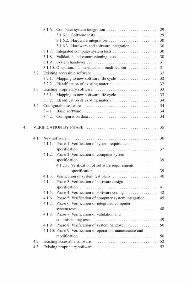
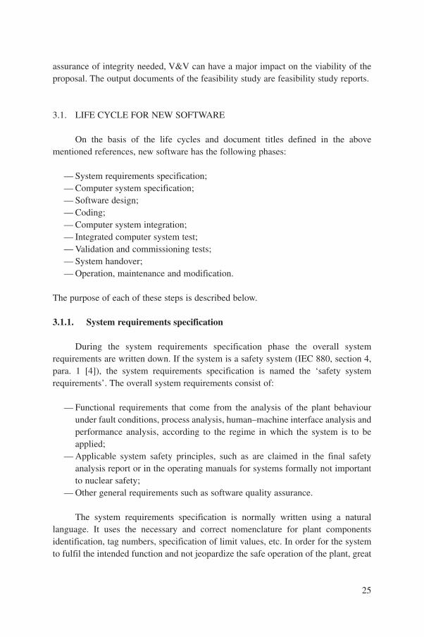
FIG. 2. Desired relationship of safety category, software type and V&V effort.
Ver
ifica
tion
and
valid
atio
n ef
fort
(arb
itrar
y un
its)
4
A
New
3
2
1
0
B
C
U
Software type
Existingaccessible
A
B
C
U
Existingproprietary
A
B
C
U
Configurable
A
B
U
C
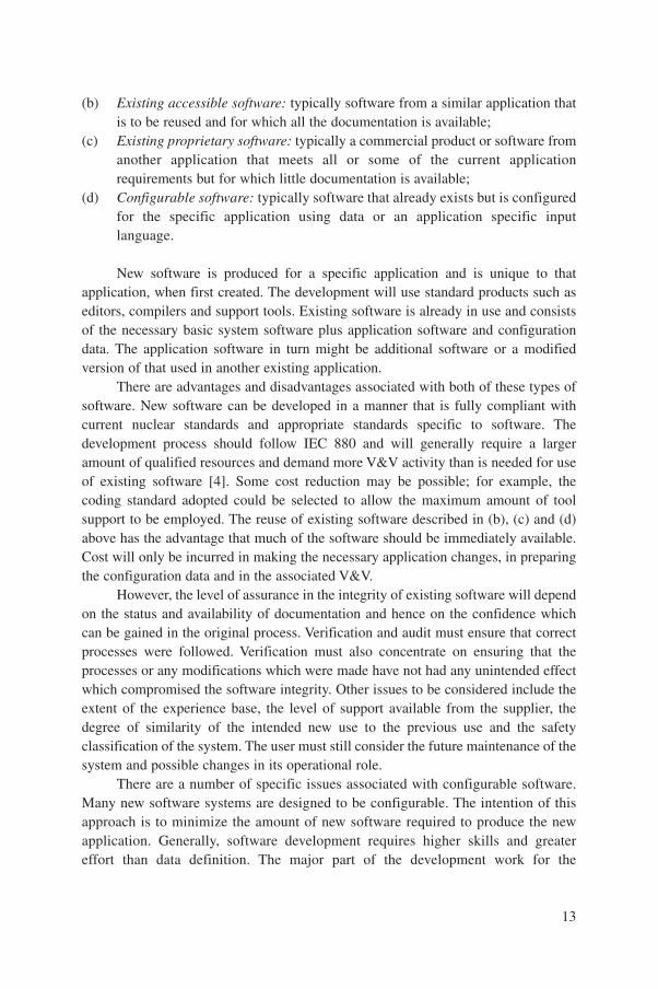
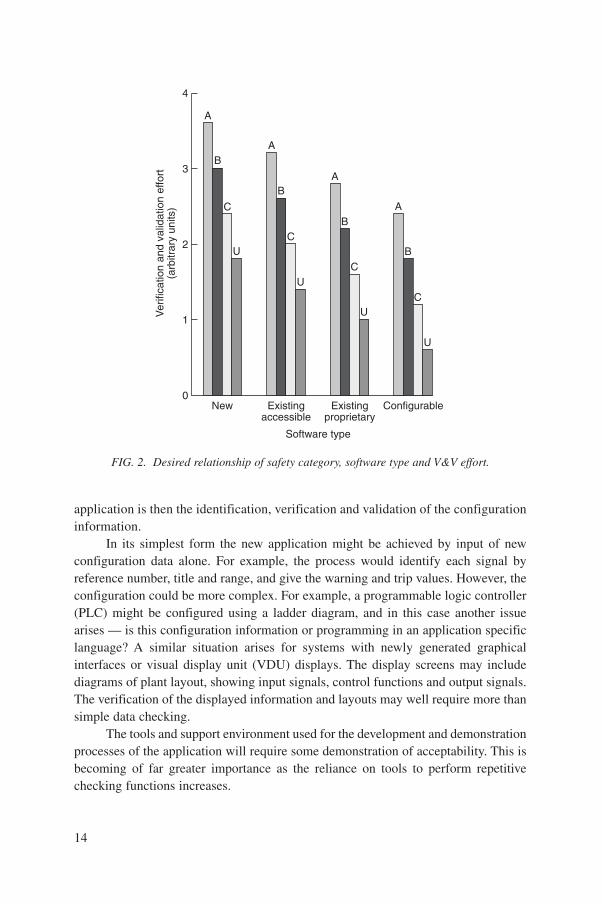
Current developments in software engineering are directed at reducing the costof implementing new systems. This applies both to costs of development and to costsof V&V. The target would be to achieve a relation between software category,software type and cost of V&V such as is shown in Fig. 2 (using arbitrary units ofeffort).
2.2.1. New software
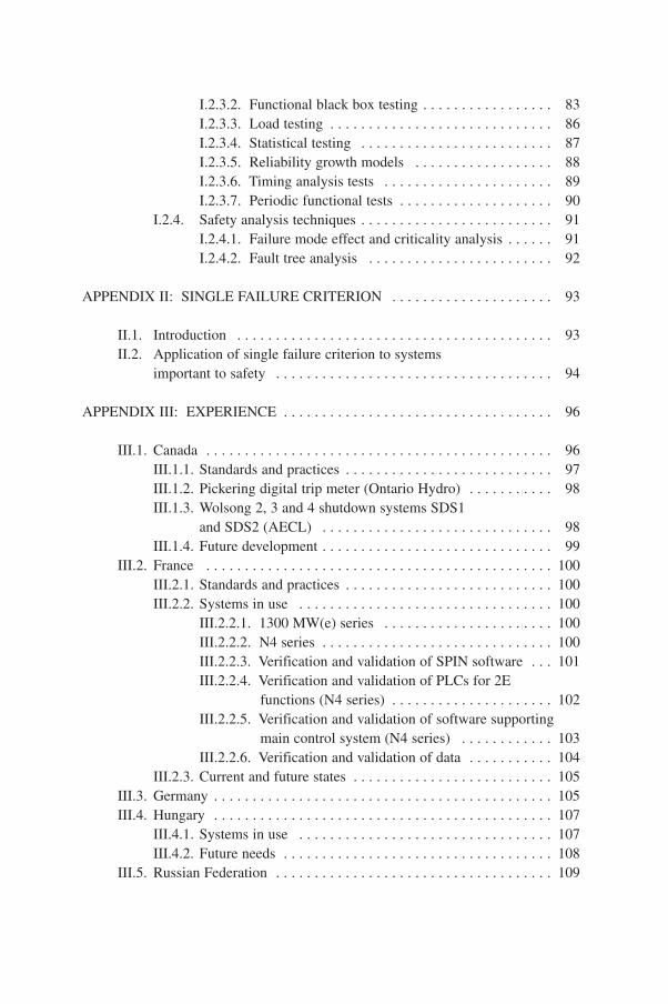
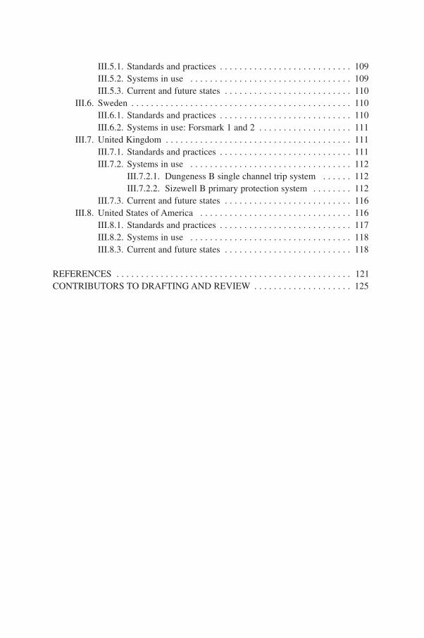
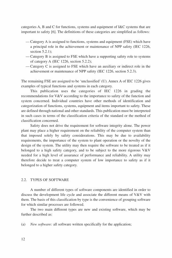
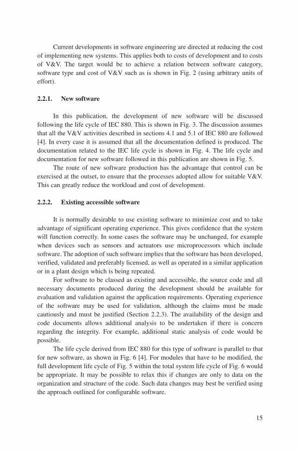
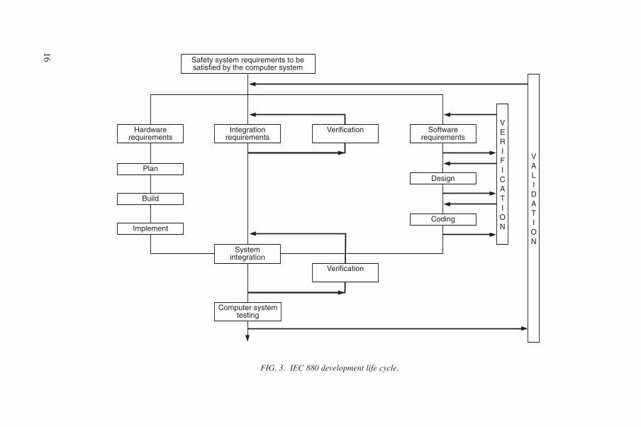
In this publication, the development of new software will be discussedfollowing the life cycle of IEC 880. This is shown in Fig. 3. The discussion assumesthat all the V&V activities described in sections 4.1 and 5.1 of IEC 880 are followed[4]. In every case it is assumed that all the documentation defined is produced. Thedocumentation related to the IEC life cycle is shown in Fig. 4. The life cycle anddocumentation for new software followed in this publication are shown in Fig. 5.
The route of new software production has the advantage that control can beexercised at the outset, to ensure that the processes adopted allow for suitable V&V.This can greatly reduce the workload and cost of development.
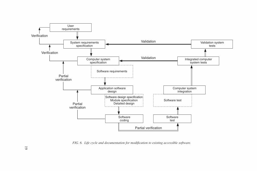
2.2.2. Existing accessible software
It is normally desirable to use existing software to minimize cost and to takeadvantage of significant operating experience. This gives confidence that the systemwill function correctly. In some cases the software may be unchanged, for examplewhen devices such as sensors and actuators use microprocessors which includesoftware. The adoption of such software implies that the software has been developed,verified, validated and preferably licensed, as well as operated in a similar applicationor in a plant design which is being repeated.
For software to be classed as existing and accessible, the source code and allnecessary documents produced during the development should be available forevaluation and validation against the application requirements. Operating experienceof the software may be used for validation, although the claims must be madecautiously and must be justified (Section 2.2.3). The availability of the design andcode documents allows additional analysis to be undertaken if there is concernregarding the integrity. For example, additional static analysis of code would bepossible.
The life cycle derived from IEC 880 for this type of software is parallel to thatfor new software, as shown in Fig. 6 [4]. For modules that have to be modified, thefull development life cycle of Fig. 5 within the total system life cycle of Fig. 6 wouldbe appropriate. It may be possible to relax this if changes are only to data on theorganization and structure of the code. Such data changes may best be verified usingthe approach outlined for configurable software.
15
16
Hardwarerequirements
Plan
Build
Implement
Integrationrequirements
Verification Softwarerequirements
Systemintegration
Verification
Safety system requirements to besatisfied by the computer system
Design
VERIFICATION
VALIDATION
Coding
Computer systemtesting
FIG. 3. IEC 880 development life cycle.

17
FIG. 4. Software development life cycle documentation based on IEC 880.
Qualityassurance plan
Softwarerequirements
Performancespecification
Specificationof periodic
testprocedures
Verificationplan
Periodictest
coverageassessment
Integrationplan
Verificationtest report
Computer systemvalidation plan
Computer systemvalidation report
Systemrequirements
Softwarerequirements
Softwaredesign
Softwarecoding
Hardware–softwareintegration
Computersystem validation
Detailedrecommendation
Safety systemrequirements
Designverification report
PHASES OF LIFE CYCLE
OUTPUT
DOCUMENTS

18
Userrequirements
System requirementsspecification
Computer systemspecification
Software requirementsHardware requirementsIntegration requirements
Softwaredesign
Softwarecoding
Software design specificationModule specification
Detailed design
Softwaretest
Software testHardware integration
Hardware–software integration
Computer systemintegration
Integrated computersystem tests
Validation systemtests
Validation
Validation
Verification
Verification
Verification
Verification
Verification
FIG. 5. Life cycle and documentation for new software.
19
FIG. 6. Life cycle and documentation for modification to existing accessible software.
Userrequirements
System requirementsspecification
Computer systemspecification
Software requirements
Application softwaredesign
Softwarecoding
Software design specificationModule specification
Detailed design
Softwaretest
Software test
Computer systemintegration
Integrated computersystem tests
Validation systemtests
Validation
Validation
Partial verification
Partialverification
Verification
Verification
Partialverification
20
FIG. 7. Life cycle and documentation for existing proprietary software.
Userrequirements
System requirementsspecification
Computer systemspecification
No documents available
Application softwaredesign
Softwarecoding
Softwaretest
Computer systemintegration
Integrated computersystem tests
Validation systemtests
Validation
Partial validation
No verification
Noverification
Verification
Verification
Noverification
No documents available No documents available
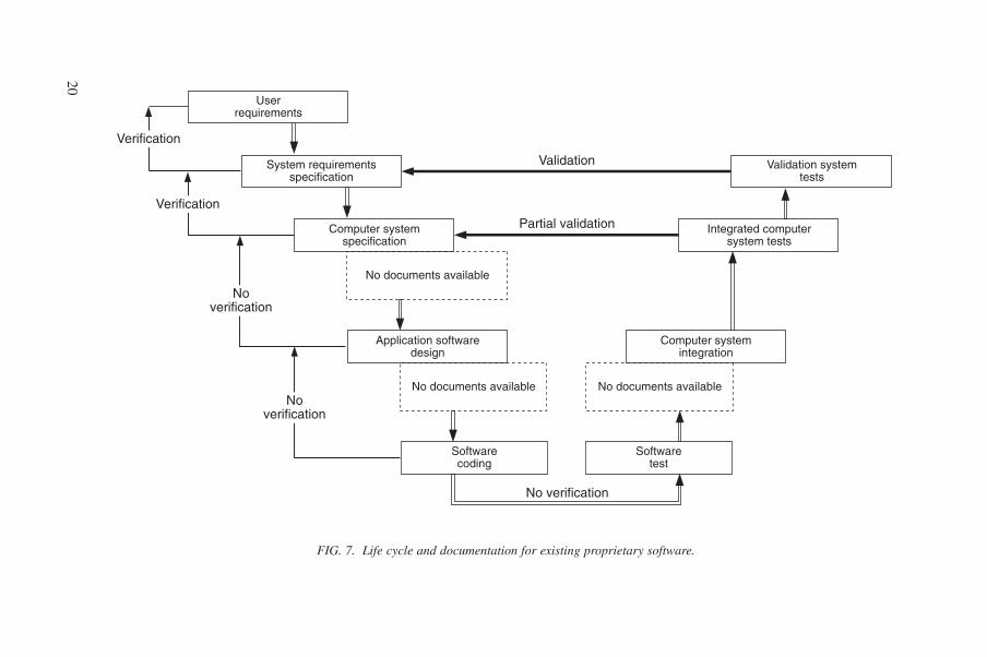
2.2.3. Existing proprietary software
Existing proprietary software is generally adopted to minimize cost. However,the source code and the development documentation are usually not available forverification. Therefore, the assessment of integrity of the application software mustbe based on validation. Hence, the development life cycle derived from IEC 880 isparallel to that for new software, as shown in Fig. 7 [4]. In this case operatingexperience and functional testing must be evaluated to compensate for the lack oforiginal documentation. It may only be possible to present an adequate justificationin this way for category C and perhaps category B systems.
Since operating experience is important in this case, it is also important todefine how this should be assessed. This will necessitate that the requirements beclarified and that the common functions provided by the software be identified. Oncethis is done, the relevance of the operating experience to each factor listed below canbe assessed:
— How many systems exist in service, identified by user and version?— How similar are the new and the evaluated systems?— Which parts of the software are used by the evaluated systems?— How much operating time exists? The records should show the amount of
continuous time, the number of years and the number of hours per day ofoperation.
— What records of failures and of revealed and corrected faults have been made?— Are the challenges to the system in the new application similar to those in the
existing applications?
It is suggested that significant operating experience is required; for example, atleast two systems should have been in operation for several months before ameaningful evaluation can be made. A statistical approach to testing anddemonstration of reliability growth may be of some value for low reliabilityrequirements, but could be misleading. In the absence of details of the code structure,Bayesian statistics should be applied to black box test results (Sections I.2.3.2 andI.2.3.4 in Appendix I).
The confidence that can ultimately be achieved will depend on co-operationbetween the system developer and the vendor of the software to complete theevaluation. This should include, for example, methods and tools for the retrospectiveevaluation of a reference installation and methodical evaluation of reported faults andfailures that have occurred. It is therefore important that the vendor has an existingprocess for handling problem reports.
21

2.2.4. Configurable software
A range of different forms of software can be described as configurable. Someforms are quite simple and are essentially data driven. Others are much more complexand functionally very rich, taking the form of application specific languages.
One form of configurable software consists of a set of basic software elementsand a set of rules describing how these elements can be combined. The user isprovided with a functional language to configure the basic elements into the desiredsystem. Examples of these basic elements are AND and OR logic functions,integrators and timers. Another form of configurable software consists of basicprocesses such as signal input, signal checking, actuator operation and packagecontrol logic.
The requirements document may be converted into logic diagrams to define thesignals and processing processes. For closed loop control these will include processessuch as signal averaging, demand change rate limits, threshold comparison,proportional–integral–derivative (PID) control, auto/manual transfer, and output andcheck-back of actuator demands for movement. For multiplexed control these willinclude operations such as valve opening and closure, with alarms generated for valvemovement failure and switchgear faults. It is usual for such operations to beperformed by standard blocks of software, configured by the supplier of theapplications software.
The process for establishing the configuration may involve the entry of signaltag numbers, ranges, control constants and their allowed ranges of adjustment,actuator tag numbers and permitted rates of operation, through a menu driven ormanual pseudo-code generation set-up process. The selection of standard modelobjects for control logic options may be followed by entry of data to define andconfigure the characteristics for a specific object. Alternative processes involve theselection and positioning of standard blocks from a menu using a computer aideddesign (CAD) package, the inclusion of signal interconnection information bydrawing lines linked with tag numbers, and the entry of tables of configurationinformation to the logic blocks.
One increasingly important form of configurable software is that used toproduce VDU displays and touch screen displays, where the display and screendesigns form the configurable information. In some systems, configuration can beperformed at set-up time on-screen, graphically, through a graphical user interface(GUI). In other cases alphanumeric data strings or menu entries define the assignmentof data to basic functions.
The deployment of existing configurable software may allow a claim thatoperating experience provides a valid justification for the correctness of the existingbasic software. Therefore, only the application specific element need be subject toV&V processes. This is the basis of the commercial dedication process being
22
developed in the USA as part of the instrumentation upgrade programme of theElectric Power Research Institute (EPRI). This includes allowance for audits of theprocedures and documentation of vendors.
Existing configurable software is often used in PLC applications. PLCs use anumber of programming concepts. Ladder logic and symbolic function blocks aretypical of the languages that are used to program PLCs. However, it has been foundthat the same ladder logic can execute in a different manner on different PLCs.Recent developments, including the use of portable equipment to reprogram PLCsin the field, have made considerable changes to their potential for different classesof use.
2.3. DEVICES CONTAINING SOFTWARE
Software is increasingly used by manufacturers of standard I&C devices tominimize product costs. One example is a microprocessor used to adjust the rangeand calibration of an instrument, rather than making the adjustment with fixedresistors and precision potentiometers. This software is often concealed, since it maynot be stated in the manufacturer’s product information that the instrument uses amicroprocessor. If it is present, then it should be subject to V&V in the same way asother accessible or proprietary software in the system.
The specification of the product and the complete user documentation shouldbe available. Traceability of the software releases should be provided with the productand the device identification details, since the software in this type of device is oftenchanged to enhance the product.
2.4. SOFTWARE TOOLS
Software tools are becoming an indispensable part of the software developmentprocess. As the dependence on software tools in the development and V&V processesincreases, so their potential to cause a fault that remains undiscovered increases. Thefaults could be simple, and result in the wrong version of software or data being usedbecause of a configuration management fault, or more complex, and result in theintroduction of illegal code owing to a code generator fault. In either case, the resultcould be catastrophic. The consequences of tool errors of this kind are such that activemeasures, based on the way software tools are used and on the way their products arechecked, should be put in place. Existing and draft software standards (such as theIEC 880 supplement [11]) generally require that the integrity of a tool be the same as
23
that of the application, but lower integrity is acceptable if the tool output can beverified. An example of such a measure is source code comparison to revealunauthorized code (Section III.7.2.2 in Appendix III).
3. SOFTWARE RELATED ACTIVITIESAND DOCUMENTS
The nuclear community currently considers that the requirements of IEC 880[4] form a good basis for the production of software for nuclear safety systems. Asindicated above, the present report assumes the development life cycle of IEC 880and that illustrated in the IAEA QA guide, Technical Reports Series No. 282 [3], andassumes classification into categories A, B and C according to IEC 1226 [6].
The life cycles are illustrated in Figs 1 and 3. Each identified activity or phasein the life cycle is cross-referenced to either IEC 880 or TRS 282. For a fullunderstanding of the different activities or phases, the reader should study thecomplete text in the two publications. The full life cycle applies to category A systemsand simplified forms of the life cycle may be applicable to category B and C systems.
This section defines activities and documentation related to the development ofany software. For systems not important to safety, activities and documentation usedfor V&V can be selected from the life cycle activities as necessary. The use ofdocumentation for V&V purposes, as a function of the system classification, isdefined in Sections 4 and 5.
Before the start of any system development, a nuclear plant project shouldrequest a feasibility study to consider the requirements and to:
— Show that at least one solution exists which is acceptable on cost and technicalgrounds, allowing for V&V;
— Find appropriate available technologies to realize the system.
The feasibility study should contain:
— A set of possible solutions ranked according to cost, risk and technologicalcomplexity or novelty;
— For each solution, the necessary planning and allocations of resources, to allowchoice of the most cost effective and best technical solution.
In ranking the solutions, the different ways of implementing a computer basedsolution should be considered, with particular reference to V&V. Since differentsolutions will place very different demands for V&V, depending on the level of
24
assurance of integrity needed, V&V can have a major impact on the viability of theproposal. The output documents of the feasibility study are feasibility study reports.
3.1. LIFE CYCLE FOR NEW SOFTWARE
On the basis of the life cycles and document titles defined in the abovementioned references, new software has the following phases:
— System requirements specification;— Computer system specification;— Software design;— Coding;— Computer system integration;— Integrated computer system test;— Validation and commissioning tests;— System handover;— Operation, maintenance and modification.
The purpose of each of these steps is described below.
3.1.1. System requirements specification
During the system requirements specification phase the overall systemrequirements are written down. If the system is a safety system (IEC 880, section 4,para. 1 [4]), the system requirements specification is named the ‘safety systemrequirements’. The overall system requirements consist of:
— Functional requirements that come from the analysis of the plant behaviourunder fault conditions, process analysis, human–machine interface analysis andperformance analysis, according to the regime in which the system is to beapplied;
— Applicable system safety principles, such as are claimed in the final safetyanalysis report or in the operating manuals for systems formally not importantto nuclear safety;
— Other general requirements such as software quality assurance.
The system requirements specification is normally written using a naturallanguage. It uses the necessary and correct nomenclature for plant componentsidentification, tag numbers, specification of limit values, etc. In order for the systemto fulfil the intended function and not jeopardize the safe operation of the plant, great
25

effort should be made in the compilation of the system requirements specification,and this is discussed in Section 1.3.1. The IAEA Technical Report TRS 282(Section 2.1) states [3]:
“The requirements specification…should contain enough information to totallyidentify and define the required functions so that the top level of softwaredesign can address all these functions in a traceable manner. To ensure that therequirements specification is read and understood, its contents should be simplyand concisely presented. It should, however, be sufficiently detailed to showhow all the relevant system requirements are being satisfied.”
The output documentation of the system requirements specification phase is thesystem requirements specification or safety system requirements specification.
3.1.2. Computer system specification
During the computer system specification phase the hardware and software ofthe computer system are described. The computer system specification states theobjectives and functions assigned to the computer system. The first part of this phasedivides the functions among hardware and software to allow the individualrequirements to be developed.
The output of this phase is the computer system specification, giving thecomputer system architecture, and is used to separate the three types of requirements:
— Software;— Hardware;— Integration.
Recommendations regarding the computer system specification can also befound in TRS 282 (Section 2.1, para. 1), described as the ‘requirements specification’,and additional information is available in IEC 880, section 4 and appendix A [3, 4].
3.1.2.1. Software requirements
The software requirements are specified in one of the three sets of documentsproduced during this phase of development. Their production is an activity in thecomputer system specification phase and the requirements are derived from thesystem requirements specification phase. The software requirements are the basis forthe software design and must contain all information necessary for the design of thesoftware.
The purpose of the software requirements is to state the software functional andperformance requirements from an external and synthetic view, without stating how
26

they are programmed. A purpose of the software quality plan (required in TRS 282,Section 3.5, and IEC 880, section 3.2) is to state the programming rules to be applied[3, 4]. Verification will be required to check that the rules have been applied.
The output document of the software requirements activity is the softwarerequirements documentation. In IEC 880, appendix F, this document is called the‘software requirements specification (functional and reliability requirements)’ [4]. InTRS 282, Section 2.1, it is called simply the ‘requirements specification’ [3].
3.1.2.2. Hardware requirements
The hardware requirements are derived and established from the systemrequirements specification as an activity in the computer system specification phase.IEC 987 [1] deals with hardware and complements IEC 880 and TRS 282 regardingthe specification, design and testing of the hardware. The hardware requirements arethe basis for the hardware design and must contain all information necessary for thedesign of the hardware.
The output of activities to define the hardware requirements is the hardwarerequirements documentation.
3.1.2.3. Integration requirements
The integration requirements are established from the system requirementsspecification by an activity in the computer system specification phase. Theintegration requirements are the basis for the integration of the hardware and softwarewithin the computer system as well as the integration of the computer system in theplant. The integration requirements contain all information necessary for these twointegration activities.
The integration requirements may be included in the software requirementsdocumentation or the hardware requirements documentation or both. The integrationrequirements may also be documented in a standalone document identified as theintegration requirements documentation.
3.1.3. System test plans
In parallel with the development of the computer system specification, it isnormal practice to complete the generation of the integrated computer system testplans. The plans are based on the system requirements specification and the computersystem requirements and are produced during this phase of the development. Theplans should include the objective, the input data and the success criteria foracceptance test performance. It is convenient to develop a matrix showing thetraceability of requirements to the system and acceptance test plans at this stage.
27
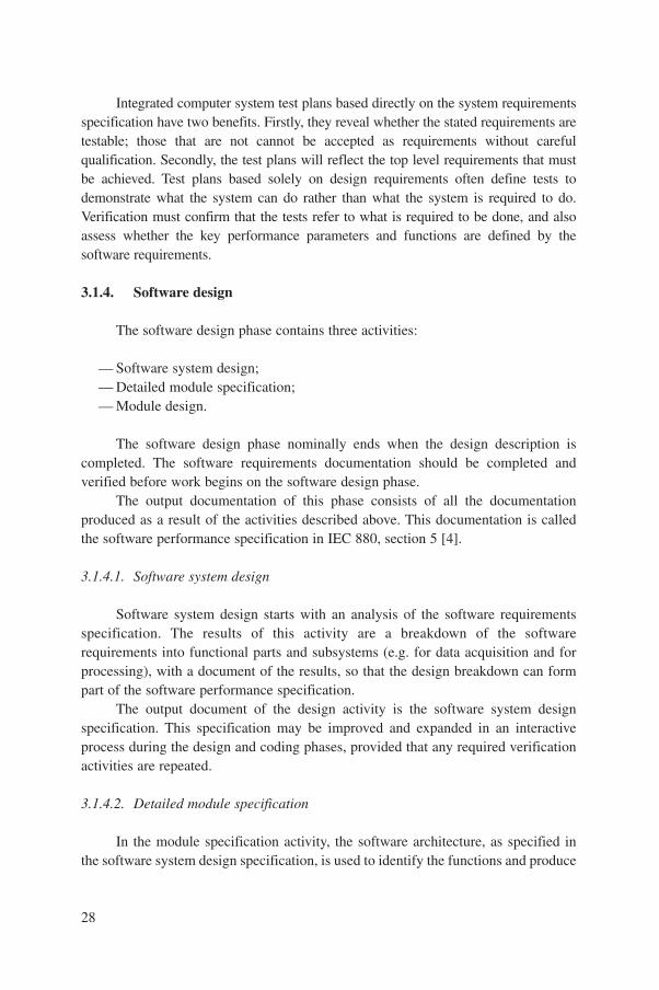
Integrated computer system test plans based directly on the system requirementsspecification have two benefits. Firstly, they reveal whether the stated requirements aretestable; those that are not cannot be accepted as requirements without carefulqualification. Secondly, the test plans will reflect the top level requirements that mustbe achieved. Test plans based solely on design requirements often define tests todemonstrate what the system can do rather than what the system is required to do.Verification must confirm that the tests refer to what is required to be done, and alsoassess whether the key performance parameters and functions are defined by thesoftware requirements.
3.1.4. Software design
The software design phase contains three activities:
— Software system design;— Detailed module specification;— Module design.
The software design phase nominally ends when the design description iscompleted. The software requirements documentation should be completed andverified before work begins on the software design phase.
The output documentation of this phase consists of all the documentationproduced as a result of the activities described above. This documentation is calledthe software performance specification in IEC 880, section 5 [4].
3.1.4.1. Software system design
Software system design starts with an analysis of the software requirementsspecification. The results of this activity are a breakdown of the softwarerequirements into functional parts and subsystems (e.g. for data acquisition and forprocessing), with a document of the results, so that the design breakdown can formpart of the software performance specification.
The output document of the design activity is the software system designspecification. This specification may be improved and expanded in an interactiveprocess during the design and coding phases, provided that any required verificationactivities are repeated.
3.1.4.2. Detailed module specification
In the module specification activity, the software architecture, as specified inthe software system design specification, is used to identify the functions and produce
28

from them the necessary level of detailed information. The functional requirementsare divided among the software modules. The modules are normally not larger than afew hundred lines of code.
The output documents of this activity are the ‘module specifications’. InTRS 282, this documentation is called the ‘detailed functional specification’ [3].
3.1.4.3. Module design
The module design activity includes definition of the actual algorithms andmathematical equations, as well as the detailed logic and data operations to be usedto perform the required functions. The module design is the basis for coding.
The output documents of this activity are the ‘detailed design specifications’,one for each module or group of modules.
3.1.5. Coding
The software design description is the input to the coding phase. In this phase,the design is translated into code in a programming language, arranged to perform thefunctions stated in the computer system specification. The product of this activity issource code, available in a form able to be read and processed by a computer.
The output documentation of this phase is a printout of the source code, or areadable electronic record of the code.
3.1.6. Computer system integration
The computer system integration phase consists of three activities:
— Software tests;— Hardware integration;— Hardware and software integration.
3.1.6.1. Software tests
Software tests may be performed on modules, on groups of modules (e.g. sub-systems) and on the entire software specified in the software requirements specification.The hardware used to test the software may be different from that which will be used inthe final system. The software tests must be performed according to a written test plan.The test plan may be part of the V&V plan or may be referenced in the V&V plan.
The output documentation of this activity is the software test report. For mostsystems this will be in the form of a set of test reports for each module and subset ofmodules, giving the test configuration, input data, acceptance criteria and commentson the results.
29
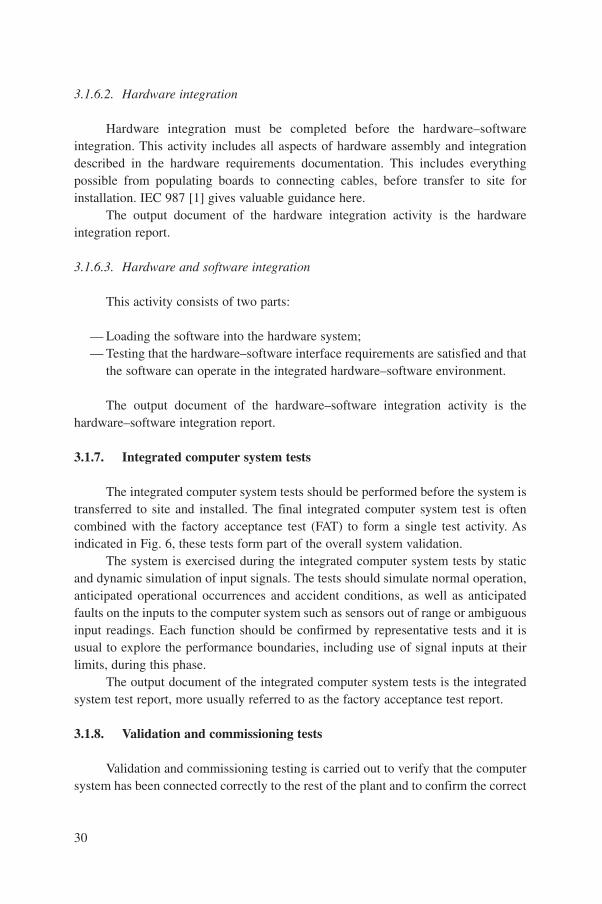
3.1.6.2. Hardware integration
Hardware integration must be completed before the hardware–softwareintegration. This activity includes all aspects of hardware assembly and integrationdescribed in the hardware requirements documentation. This includes everythingpossible from populating boards to connecting cables, before transfer to site forinstallation. IEC 987 [1] gives valuable guidance here.
The output document of the hardware integration activity is the hardwareintegration report.
3.1.6.3. Hardware and software integration
This activity consists of two parts:
— Loading the software into the hardware system;— Testing that the hardware–software interface requirements are satisfied and that
the software can operate in the integrated hardware–software environment.
The output document of the hardware–software integration activity is thehardware–software integration report.
3.1.7. Integrated computer system tests
The integrated computer system tests should be performed before the system istransferred to site and installed. The final integrated computer system test is oftencombined with the factory acceptance test (FAT) to form a single test activity. Asindicated in Fig. 6, these tests form part of the overall system validation.
The system is exercised during the integrated computer system tests by staticand dynamic simulation of input signals. The tests should simulate normal operation,anticipated operational occurrences and accident conditions, as well as anticipatedfaults on the inputs to the computer system such as sensors out of range or ambiguousinput readings. Each function should be confirmed by representative tests and it isusual to explore the performance boundaries, including use of signal inputs at theirlimits, during this phase.
The output document of the integrated computer system tests is the integratedsystem test report, more usually referred to as the factory acceptance test report.
3.1.8. Validation and commissioning tests
Validation and commissioning testing is carried out to verify that the computersystem has been connected correctly to the rest of the plant and to confirm the correct
30
action of the system. The actions tested should cover all normal operation, anticipatedoperational occurrences and accident conditions as well as anticipated faults. Allinput conditions should be represented directly or simulated at the inputs to thecomputer. Each function should be systematically confirmed directly or byrepresentative tests. However, it may not be possible to perform complete tests in allcases owing to restrictions on the operation of the plant or the system whose functionsthe computer system supports.
The validation and commissioning tests are usually combined with the siteacceptance test (SAT), which includes verification of the operation and maintenanceof the equipment.
The output documentation of the validation and commissioning tests phase isthe commissioning test report, more usually referred to as the site acceptance testreport.
3.1.9. System handover
Handover is a milestone in the project rather than a project phase. Theresponsibility for the system is transferred from the developer or system supplier to theuser on successful completion of the validation and commissioning tests. It isnecessary to establish that all requirements which the user has specified havebeen met.
The output documentation of handover includes a list of all items still to beresolved. This protocol must be agreed and approved by both parties.
3.1.10. Operation, maintenance and modification
During the operation, maintenance and modification phases, the system is inoperation and may be subject to:
— Periodic tests, performed in order to verify that the system is not degrading;— Modifications, implemented to enhance or change the functionality or to
correct errors, in which case regression testing will be required;— Change of parameters;— Diagnosis activities, e.g. the execution of special diagnostic programs;— Hardware components replacement, as made necessary by random
failures.
The output documentation of the operation and maintenance phase includes logbooks, maintenance reports, periodic test reports and other relevant operation reports,including anomaly reports. If any form of modification is required (adaptive orcorrective), then an appropriate life cycle for implementing a change would be
31
required. This life cycle should contain the phases of the main development,including V&V. These activities together with an impact analysis and regressiontesting will be necessary to ensure that the changes have been correctly implementedand no new errors introduced. This is part of the justification needed to return thesystem to service.
3.2. EXISTING ACCESSIBLE SOFTWARE
When a system is built of both new software and existing accessible software,the new system should be developed as described in Section 3.1. The existingsoftware may be modified and integrated as described below.
3.2.1. Mapping to new software life cycle
When a system is built from existing accessible software, the documents andrelated information belonging to the product should be assembled and mappeddirectly onto corresponding information requirements of the life cycle for newsoftware outlined above. The material should then be reviewed to ensure that it meetsthe requirements of the new software life cycle for development and verificationdocuments and records.
Even if no changes of function of the accessible software components arerequired, new sets of documents for integrated computer system tests and forvalidation and commissioning tests are required. New FAT and SAT documents areneeded, unless the system is a replication with no changes at all. These will have tobe prepared from the new system requirements. If software change is required, whichis usually expected, then a modification process will have to be adopted. This processshould follow the development life cycle for new software, and should result in a newor revised set of documentation. The content of this may be quite similar to theexisting documents, depending on the scale of change. This change life cycle couldbe identical to the life cycle used to complete any work that has to be done again forthe development of new software for the system.
3.2.2. Identification of existing material
The following material should be identified when completing the mapping ofthe material of the existing product to the life cycle identified for new software:
— System requirements specification;— Computer system specification:
• Software requirements specification,
32
• Hardware requirements specification,• Integration requirements specification;
— Software performance specification:• Software system design specification,• Module specification,• Detailed design specification;
— Printout of source code;— System integration report:
• Software test report,• Hardware integration report,• Hardware–software integration report;
— Integrated system test report/factory acceptance test report;— Commissioning test report/site acceptance test report;— Operation, maintenance and modification reports.
If the software has been used in a system of a similar safety category orintegrity requirement, there may be extensive documentation from processesundertaken for an independent assessment and for licensing. This will be in additionto the documentation available from the development process. This material shouldbe available to the licensee and will form an important part of the demonstration thatthe software is adequate for its intended use. This demonstration is particularlyimportant for the higher safety categories of software.
3.3. EXISTING PROPRIETARY SOFTWARE
When a system is built up of both new software and existing proprietarysoftware, the new software is developed as outlined in Section 3.1. The existingproprietary software may be integrated as described below.
3.3.1. Mapping to new software life cycle
The following system life cycle activities should be performed fully when usingexisting proprietary software:
— System requirements specification (Section 3.1.1);— Integrated computer system tests (Section 3.1.7);— Validation and commissioning tests (Section 3.1.8);— System handover (Section 3.1.9);— Operation, maintenance and modification (Section 3.1.10).
33
3.3.2. Identification of existing material
For existing proprietary software, the full documentation identified inSection 3.1 is not normally available for evaluation. To compensate for this, operatingexperience feedback is used to support the evaluation of the software. Experiencefeedback should use records with suitable QA, over suitable periods, as described inSection 2.2.3. Additional testing requirements will have to be derived from the newsystem requirements. The process requires that the documents of the integrated systemtests and the validation and commissioning tests be generated, and the tests done.
For proprietary software only part of the documentation listed in Section 3.2.2may be available. Depending on the safety category, documents described in Sections3.1.2–3.1.5 may have to be generated.
If the same proprietary software has been used before, additionaldocumentation may exist. Third party assessments and the justification done todemonstrate fitness for purpose of the software should be investigated, since thiswork normally produces extensive documentation. The availability of thisdocumentation will greatly aid system justification. However, it is unlikely thatapplication of the software in a category A system would be acceptable without asimilar level of demonstration to that provided for accessible software.
3.4. CONFIGURABLE SOFTWARE
Configurable software is discussed with respect to its two parts, the basicsoftware and the application specific configuration data. The former could be theoperating system in a PLC or the standard functional modules available. The latterwill be configuration data to define parameters such as signal ranges, alarm and triplevels, actuator and sensor identities, actuator and sensor names, functions assignedto each control switch and actuator, and other plant characteristics.
3.4.1. Basic software
The basic software is normally either existing accessible software or existingproprietary software. Depending on the case, the reader is referred to Section 3.2 or3.3 for the documents and activities needed.
3.4.2. Configuration data
Although the data form an integral part of the total software, they can beseparated from it. This allows software to be developed as a service, configured bythe data for each application. The application data can then be prepared from the plant
34
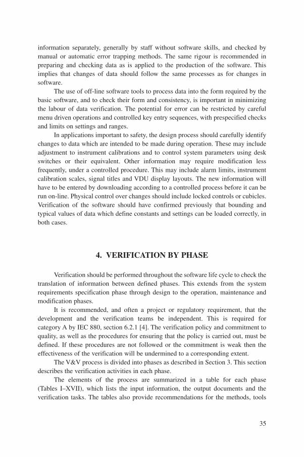
information separately, generally by staff without software skills, and checked bymanual or automatic error trapping methods. The same rigour is recommended inpreparing and checking data as is applied to the production of the software. Thisimplies that changes of data should follow the same processes as for changes insoftware.
The use of off-line software tools to process data into the form required by thebasic software, and to check their form and consistency, is important in minimizingthe labour of data verification. The potential for error can be restricted by carefulmenu driven operations and controlled key entry sequences, with prespecified checksand limits on settings and ranges.
In applications important to safety, the design process should carefully identifychanges to data which are intended to be made during operation. These may includeadjustment to instrument calibrations and to control system parameters using deskswitches or their equivalent. Other information may require modification lessfrequently, under a controlled procedure. This may include alarm limits, instrumentcalibration scales, signal titles and VDU display layouts. The new information willhave to be entered by downloading according to a controlled process before it can berun on-line. Physical control over changes should include locked controls or cubicles.Verification of the software should have confirmed previously that bounding andtypical values of data which define constants and settings can be loaded correctly, inboth cases.
4. VERIFICATION BY PHASE
Verification should be performed throughout the software life cycle to check thetranslation of information between defined phases. This extends from the systemrequirements specification phase through design to the operation, maintenance andmodification phases.
It is recommended, and often a project or regulatory requirement, that thedevelopment and the verification teams be independent. This is required forcategory A by IEC 880, section 6.2.1 [4]. The verification policy and commitment toquality, as well as the procedures for ensuring that the policy is carried out, must bedefined. If these procedures are not followed or the commitment is weak then theeffectiveness of the verification will be undermined to a corresponding extent.
The V&V process is divided into phases as described in Section 3. This sectiondescribes the verification activities in each phase.
The elements of the process are summarized in a table for each phase(Tables I–XVII), which lists the input information, the output documents and theverification tasks. The tables also provide recommendations for the methods, tools
35

and techniques that can be applied to each category of software as determined by IEC1226 [6]. The activities, with recommended or optional verification methods, arelisted in the tables.
The purpose of verification of each phase is to confirm that the developmentproducts from that phase correctly reflect the requirements that served as inputs tothat phase. The input and output documents listed in the tables are those used forverifying the phase, and not only the output documents of the phase activity. Theverification process consists of reviewing input documents, code and data, andapplying various tools and techniques to them to produce output documents thatcontain the results of the verification. Review is an important activity and it is definedin Section 1.5. Two review techniques are identified and described in Appendix I:walk-through and inspection.
4.1. NEW SOFTWARE
The verification of new software is based on the phased developmentprogramme. The system development plan has to identify clearly the developmentphases that are to be used. Each phase should be defined with respect to the requiredinputs, the specific activities and the expected outputs. The verification methods foridentification of potential problems within the phase and the manner in which theverification team will be given access to the products of the phase should be defined.
Software verification usually begins with the software requirementsspecification. Experience has demonstrated that some failures in the software ofcritical systems can be traced to errors in the system specification. This specificationshould be verified, but this is not usually the responsibility of the software engineer.If the software developer finds that something was either misinterpreted or leftundefined in the system specification, an anomaly report should be raised for thespecification. The system design decision should not be made by the softwaredeveloper.
The phases to be used in the development cycle are not prescribed here.However, information on applying verification will be illustrated using thedevelopment phases described in Section 3.1 and repeated below:
— System requirements specification;— Computer system specification;— Software design;— Coding;— Computer system integration;— Integrated computer system test;— Validation and commissioning tests;
36
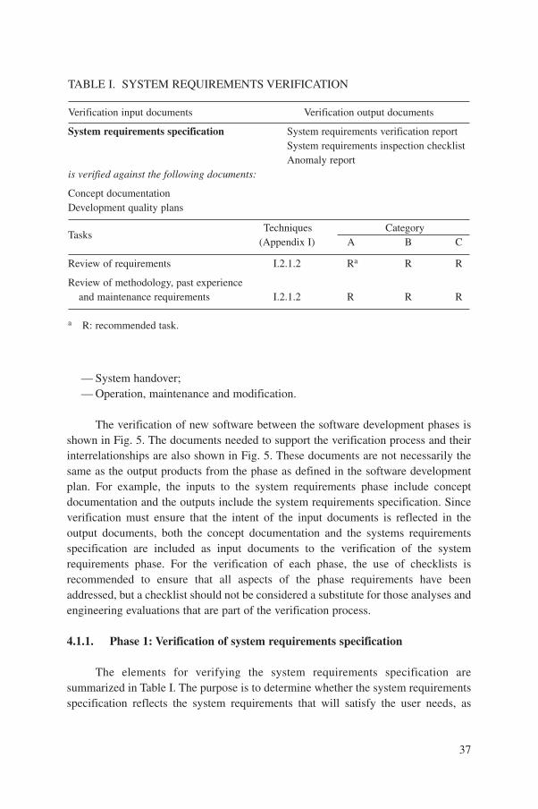
— System handover;— Operation, maintenance and modification.
The verification of new software between the software development phases isshown in Fig. 5. The documents needed to support the verification process and theirinterrelationships are also shown in Fig. 5. These documents are not necessarily thesame as the output products from the phase as defined in the software developmentplan. For example, the inputs to the system requirements phase include conceptdocumentation and the outputs include the system requirements specification. Sinceverification must ensure that the intent of the input documents is reflected in theoutput documents, both the concept documentation and the systems requirementsspecification are included as input documents to the verification of the systemrequirements phase. For the verification of each phase, the use of checklists isrecommended to ensure that all aspects of the phase requirements have beenaddressed, but a checklist should not be considered a substitute for those analyses andengineering evaluations that are part of the verification process.
4.1.1. Phase 1: Verification of system requirements specification
The elements for verifying the system requirements specification aresummarized in Table I. The purpose is to determine whether the system requirementsspecification reflects the system requirements that will satisfy the user needs, as
37
TABLE I. SYSTEM REQUIREMENTS VERIFICATION
Verification input documents Verification output documents
System requirements specification System requirements verification reportSystem requirements inspection checklistAnomaly report
is verified against the following documents:
Concept documentationDevelopment quality plans
TasksTechniques Category
(Appendix I) A B C
Review of requirements I.2.1.2 Ra R R
Review of methodology, past experienceand maintenance requirements I.2.1.2 R R R
a R: recommended task.
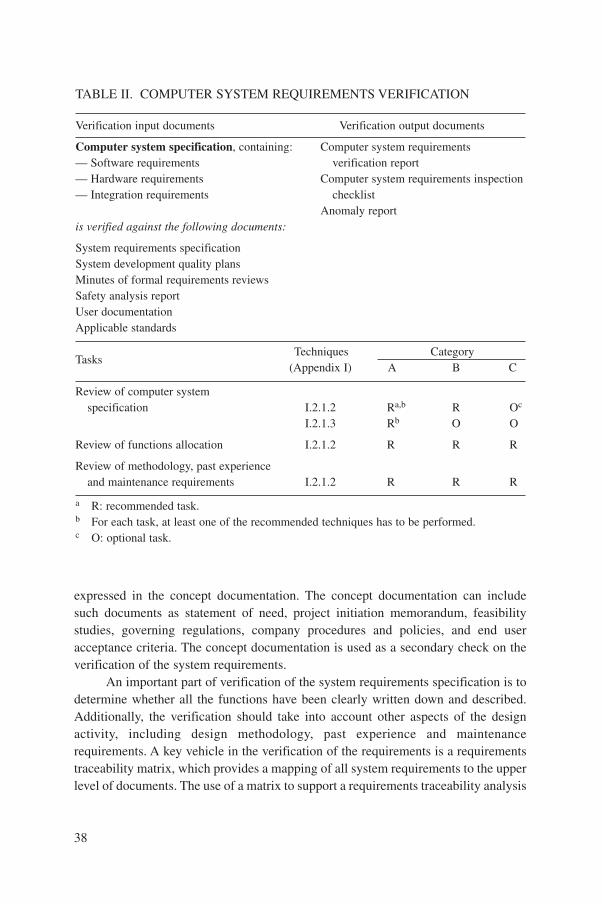
expressed in the concept documentation. The concept documentation can includesuch documents as statement of need, project initiation memorandum, feasibilitystudies, governing regulations, company procedures and policies, and end useracceptance criteria. The concept documentation is used as a secondary check on theverification of the system requirements.
An important part of verification of the system requirements specification is todetermine whether all the functions have been clearly written down and described.Additionally, the verification should take into account other aspects of the designactivity, including design methodology, past experience and maintenancerequirements. A key vehicle in the verification of the requirements is a requirementstraceability matrix, which provides a mapping of all system requirements to the upperlevel of documents. The use of a matrix to support a requirements traceability analysis
38
TABLE II. COMPUTER SYSTEM REQUIREMENTS VERIFICATION
Verification input documents Verification output documents
Computer system specification, containing: Computer system requirements— Software requirements verification report— Hardware requirements Computer system requirements inspection— Integration requirements checklist
Anomaly reportis verified against the following documents:
System requirements specificationSystem development quality plansMinutes of formal requirements reviewsSafety analysis reportUser documentationApplicable standards
TasksTechniques Category
(Appendix I) A B C
Review of computer systemspecification I.2.1.2 Ra,b R Oc
I.2.1.3 Rb O O
Review of functions allocation I.2.1.2 R R R
Review of methodology, past experienceand maintenance requirements I.2.1.2 R R R
a R: recommended task.b For each task, at least one of the recommended techniques has to be performed.c O: optional task.
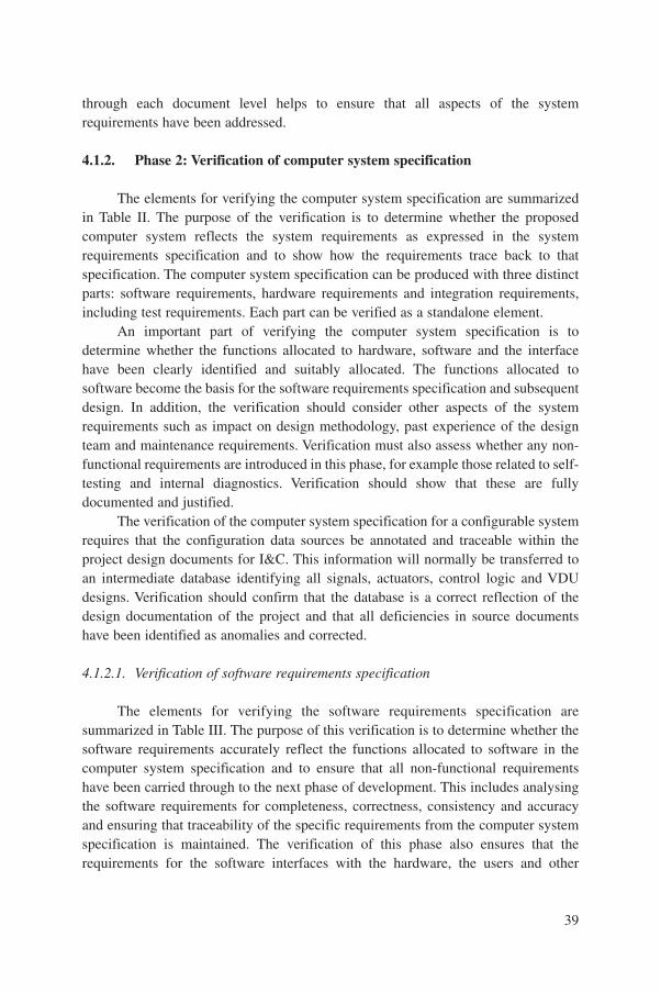
through each document level helps to ensure that all aspects of the systemrequirements have been addressed.
4.1.2. Phase 2: Verification of computer system specification
The elements for verifying the computer system specification are summarizedin Table II. The purpose of the verification is to determine whether the proposedcomputer system reflects the system requirements as expressed in the systemrequirements specification and to show how the requirements trace back to thatspecification. The computer system specification can be produced with three distinctparts: software requirements, hardware requirements and integration requirements,including test requirements. Each part can be verified as a standalone element.
An important part of verifying the computer system specification is todetermine whether the functions allocated to hardware, software and the interfacehave been clearly identified and suitably allocated. The functions allocated tosoftware become the basis for the software requirements specification and subsequentdesign. In addition, the verification should consider other aspects of the systemrequirements such as impact on design methodology, past experience of the designteam and maintenance requirements. Verification must also assess whether any non-functional requirements are introduced in this phase, for example those related to self-testing and internal diagnostics. Verification should show that these are fullydocumented and justified.
The verification of the computer system specification for a configurable systemrequires that the configuration data sources be annotated and traceable within theproject design documents for I&C. This information will normally be transferred toan intermediate database identifying all signals, actuators, control logic and VDUdesigns. Verification should confirm that the database is a correct reflection of thedesign documentation of the project and that all deficiencies in source documentshave been identified as anomalies and corrected.
4.1.2.1. Verification of software requirements specification
The elements for verifying the software requirements specification aresummarized in Table III. The purpose of this verification is to determine whether thesoftware requirements accurately reflect the functions allocated to software in thecomputer system specification and to ensure that all non-functional requirementshave been carried through to the next phase of development. This includes analysingthe software requirements for completeness, correctness, consistency and accuracyand ensuring that traceability of the specific requirements from the computer systemspecification is maintained. The verification of this phase also ensures that therequirements for the software interfaces with the hardware, the users and other
39
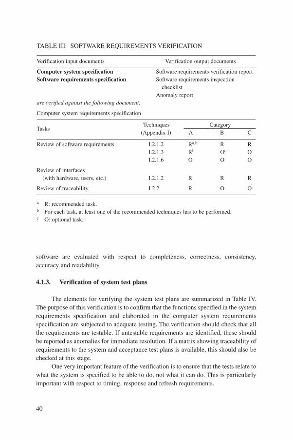
software are evaluated with respect to completeness, correctness, consistency,accuracy and readability.
4.1.3. Verification of system test plans
The elements for verifying the system test plans are summarized in Table IV.The purpose of this verification is to confirm that the functions specified in the systemrequirements specification and elaborated in the computer system requirementsspecification are subjected to adequate testing. The verification should check that allthe requirements are testable. If untestable requirements are identified, these shouldbe reported as anomalies for immediate resolution. If a matrix showing traceability ofrequirements to the system and acceptance test plans is available, this should also bechecked at this stage.
One very important feature of the verification is to ensure that the tests relate towhat the system is specified to be able to do, not what it can do. This is particularlyimportant with respect to timing, response and refresh requirements.
40
TABLE III. SOFTWARE REQUIREMENTS VERIFICATION
Verification input documents Verification output documents
Computer system specification Software requirements verification reportSoftware requirements specification Software requirements inspection
checklistAnomaly report
are verified against the following document:
Computer system requirements specification
TasksTechniques Category
(Appendix I) A B C
Review of software requirements I.2.1.2 Ra,b R RI.2.1.3 Rb Oc OI.2.1.6 O O O
Review of interfaces(with hardware, users, etc.) I.2.1.2 R R R
Review of traceability I.2.2 R O O
a R: recommended task.b For each task, at least one of the recommended techniques has to be performed.c O: optional task.

4.1.4. Phase 3: Verification of software design specification
The elements for verification of the software design specification aresummarized in Table V. The purpose of verification is to confirm that the softwaredesign specification correctly represents the software requirements and that thedesign will satisfy the needs of the user as expressed in the system documentation.
An important part of the verification is to ensure that all of the functionsallocated to software have been clearly incorporated into the design and to ensure thatno extra functions have been added. The activities should ensure that the design istraceable to the required functions. Any design features added to meet non-functionalrequirements during this phase must be identified and justified. This includes thesystem health and self-test functions. The verification should not comment on thedesirability of such features in the overall context of the application. However, it mustcheck that the information or action offered by the non-functional requirement iscompliant with the software requirements specification. It is noted in this context thatan application system that includes continuous self-test functions could fail in theself-test mode, and would thus not be available to execute its safety function.
Verification of the software design should assess the data requirements withregard to the software requirements, and also check whether the required data areavailable. Methods of verification of configuration data should be identified andshown to be feasible using sample data. The verification must determine whether therequired standards, practices and conventions are being followed sufficiently closelyduring the design process. It should consider other aspects of the design and the needs
41
TABLE IV. SYSTEM TEST PLANS VERIFICATION
Verification input documents Verification output documents
System test plan Software test plan verification reportis verified against the following documents:
System requirements specificationComputer system requirements specificationSystem development quality plans
TasksTechniques Category
(Appendix I) A B C
Review of test plan I.2.1.2 Ra R R
Review of traceability I.2.2 R Ob O
a R: recommended task.b O: optional task.
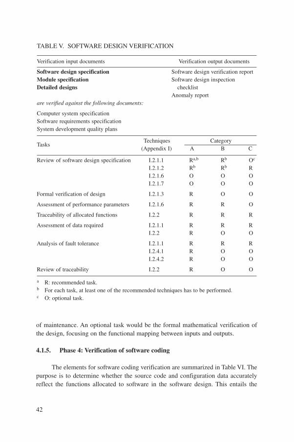
of maintenance. An optional task would be the formal mathematical verification ofthe design, focusing on the functional mapping between inputs and outputs.
4.1.5. Phase 4: Verification of software coding
The elements for software coding verification are summarized in Table VI. Thepurpose is to determine whether the source code and configuration data accuratelyreflect the functions allocated to software in the software design. This entails the
42
TABLE V. SOFTWARE DESIGN VERIFICATION
Verification input documents Verification output documents
Software design specification Software design verification reportModule specification Software design inspectionDetailed designs checklist
Anomaly reportare verified against the following documents:
Computer system specificationSoftware requirements specificationSystem development quality plans
TasksTechniques Category
(Appendix I) A B C
Review of software design specification I.2.1.1 Ra,b Rb Oc
I.2.1.2 Rb Rb RI.2.1.6 O O OI.2.1.7 O O O
Formal verification of design I.2.1.3 R O O
Assessment of performance parameters I.2.1.6 R R O
Traceability of allocated functions I.2.2 R R R
Assessment of data required I.2.1.1 R R RI.2.2 R O O
Analysis of fault tolerance I.2.1.1 R R RI.2.4.1 R O OI.2.4.2 R O O
Review of traceability I.2.2 R O O
a R: recommended task.b For each task, at least one of the recommended techniques has to be performed.c O: optional task.
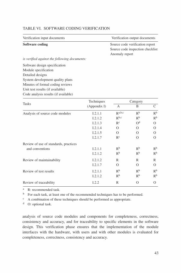
analysis of source code modules and components for completeness, correctness,consistency and accuracy, and for traceability to specific elements in the softwaredesign. This verification phase ensures that the implementation of the moduleinterfaces with the hardware, with users and with other modules is evaluated forcompleteness, correctness, consistency and accuracy.
43
TABLE VI. SOFTWARE CODING VERIFICATION
Verification input documents Verification output documents
Software coding Source code verification reportSource code inspection checklistAnomaly report
is verified against the following documents:
Software design specificationModule specificationDetailed designsSystem development quality plansMinutes of formal coding reviewsUnit test results (if available)Code analysis results (if available)
TasksTechniques Category
(Appendix I) A B C
Analysis of source code modules I.2.1.1 Ra,b,c Rb Rb
I.2.1.2 Rb,c Rb Rb
I.2.1.3 Rc Od OI.2.1.4 O O OI.2.1.5 O O OI.2.1.7 Rc O O
Review of use of standards, practicesand conventions I.2.1.1 Rb Rb Rb
I.2.1.2 Rb Rb Rb
Review of maintainability I.2.1.2 R R RI.2.1.7 O O O
Review of test results I.2.1.1 Rb Rb Rb
I.2.1.2 Rb Rb Rb
Review of traceability I.2.2 R O O
a R: recommended task.b For each task, at least one of the recommended techniques has to be performed.c A combination of these techniques should be performed as appropriate.d O: optional task.
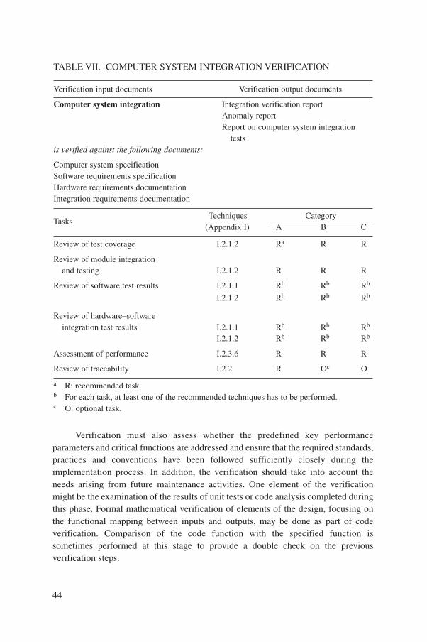
Verification must also assess whether the predefined key performanceparameters and critical functions are addressed and ensure that the required standards,practices and conventions have been followed sufficiently closely during theimplementation process. In addition, the verification should take into account theneeds arising from future maintenance activities. One element of the verificationmight be the examination of the results of unit tests or code analysis completed duringthis phase. Formal mathematical verification of elements of the design, focusing onthe functional mapping between inputs and outputs, may be done as part of codeverification. Comparison of the code function with the specified function issometimes performed at this stage to provide a double check on the previousverification steps.
44
TABLE VII. COMPUTER SYSTEM INTEGRATION VERIFICATION
Verification input documents Verification output documents
Computer system integration Integration verification reportAnomaly reportReport on computer system integration
testsis verified against the following documents:
Computer system specificationSoftware requirements specificationHardware requirements documentationIntegration requirements documentation
TasksTechniques Category
(Appendix I) A B C
Review of test coverage I.2.1.2 Ra R R
Review of module integrationand testing I.2.1.2 R R R
Review of software test results I.2.1.1 Rb Rb Rb
I.2.1.2 Rb Rb Rb
Review of hardware–softwareintegration test results I.2.1.1 Rb Rb Rb
I.2.1.2 Rb Rb Rb
Assessment of performance I.2.3.6 R R R
Review of traceability I.2.2 R Oc O
a R: recommended task.b For each task, at least one of the recommended techniques has to be performed.c O: optional task.

For configurable software, the equivalent to code verification is the verificationof the detailed configuration data. In some cases the data will be expressed asextensive data declarations in the code. In other cases the data may be preparedmanually from documents or by tools from databases and formatted for use bysoftware. The data, as source code, or in formatted form, should be verified againstthe design document by inspection and by the use of software tools to check forcompleteness, consistency and accuracy.
4.1.6. Phase 5: Verification of computer system integration
The elements for verifying the computer system integration are summarized inTable VII. A list of test techniques related to the verification of the integration ofsoftware and hardware is provided in Table VIII. The purpose is to check that thefunctions allocated to software in the system design are correctly demonstrated by thetests on the integrated software.
45
TABLE VIII. METHODS FOR COMPUTER SYSTEM INTEGRATION TEST
Input documents Output documents
Computer system integration Anomaly reportReport on computer system integration
tasksis tested against the following documents:
Computer system specificationSoftware requirements specificationHardware requirements documentationIntegration requirements documentation
TechniquesReferences Category
(Appendix I) A B C
White box testing I.2.3.1 Ra R Ob
Black box testing I.2.3.2 R R R
Load testing I.2.3.3 Rc Rc Rc
Statistical testing I.2.3.4 O O O
Reliability growth model I.2.3.5 n.a.d O O
Timing analysis I.2.3.6 Oc Oc Oc
a R: recommended task.b O: optional task.c Recommended if load and timing cannot be demonstrated by deterministic methods.d n.a.: not applicable.
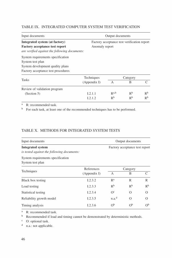
46
TABLE IX. INTEGRATED COMPUTER SYSTEM TEST VERIFICATION
Input documents Output documents
Integrated system (at factory) Factory acceptance test verification reportFactory acceptance test report Anomaly reportare verified against the following documents:
System requirements specificationSystem test planSystem development quality plansFactory acceptance test procedures
TasksTechniques Category
(Appendix I) A B C
Review of validation program(Section 5) I.2.1.1 Ra,b Rb Rb
I.2.1.2 Rb Rb Rb
a R: recommended task.b For each task, at least one of the recommended techniques has to be performed.
TABLE X. METHODS FOR INTEGRATED SYSTEM TESTS
Input documents Output documents
Integrated system Factory acceptance test reportis tested against the following documents:
System requirements specificationSystem test plan
TechniquesReferences Category
(Appendix I) A B C
Black box testing I.2.3.2 Ra R R
Load testing I.2.3.3 Rb Rb Rb
Statistical testing I.2.3.4 Oc O O
Reliability growth model I.2.3.5 n.a.d O O
Timing analysis I.2.3.6 Ob Ob Ob
a R: recommended task.b Recommended if load and timing cannot be demonstrated by deterministic methods.c O: optional task.d n.a.: not applicable.
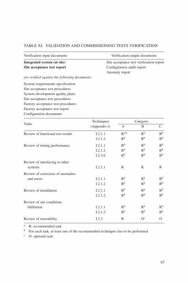
47
TABLE XI. VALIDATION AND COMMISSIONING TESTS VERIFICATION
Verification input documents Verification output documents
Integrated system (at site) Site acceptance test verification reportSite acceptance test report Configuration audit report
Anomaly report are verified against the following documents:
System requirements specificationSite acceptance test proceduresSystem development quality plansSite acceptance test proceduresFactory acceptance test proceduresFactory acceptance test reportConfiguration documents
TasksTechniques Category
(Appendix I) A B C
Review of functional test results I.2.1.1 Ra,b Rb Rb
I.2.1.2 Rb Rb Rb
Review of timing performance I.2.1.1 Rb Rb Rb
I.2.1.2 Rb Rb Rb
I.2.3.6 Rb Rb Rb
Review of interfacing to othersystems I.2.1.1 R R R
Review of correction of anomaliesand errors I.2.1.1 Rb Rb Rb
I.2.1.2 Rb Rb Rb
Review of installation I.2.1.1 Rb Rb Rb
I.2.1.2 Rb Rb Rb
Review of site conditionsfulfilment I.2.1.1 Rb Rb Rb
I.2.1.2 Rb Rb Rb
Review of traceability I.2.2 R Oc O
a R: recommended task.b For each task, at least one of the recommended techniques has to be performed.c O: optional task.
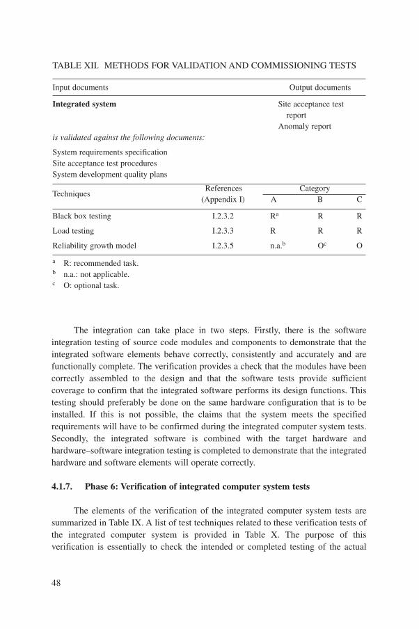
The integration can take place in two steps. Firstly, there is the softwareintegration testing of source code modules and components to demonstrate that theintegrated software elements behave correctly, consistently and accurately and arefunctionally complete. The verification provides a check that the modules have beencorrectly assembled to the design and that the software tests provide sufficientcoverage to confirm that the integrated software performs its design functions. Thistesting should preferably be done on the same hardware configuration that is to beinstalled. If this is not possible, the claims that the system meets the specifiedrequirements will have to be confirmed during the integrated computer system tests.Secondly, the integrated software is combined with the target hardware andhardware–software integration testing is completed to demonstrate that the integratedhardware and software elements will operate correctly.
4.1.7. Phase 6: Verification of integrated computer system tests
The elements of the verification of the integrated computer system tests aresummarized in Table IX. A list of test techniques related to these verification tests ofthe integrated computer system is provided in Table X. The purpose of thisverification is essentially to check the intended or completed testing of the actual
48
TABLE XII. METHODS FOR VALIDATION AND COMMISSIONING TESTS
Input documents Output documents
Integrated system Site acceptance testreport
Anomaly report is validated against the following documents:
System requirements specificationSite acceptance test proceduresSystem development quality plans
TechniquesReferences Category
(Appendix I) A B C
Black box testing I.2.3.2 Ra R R
Load testing I.2.3.3 R R R
Reliability growth model I.2.3.5 n.a.b Oc O
a R: recommended task.b n.a.: not applicable.c O: optional task.
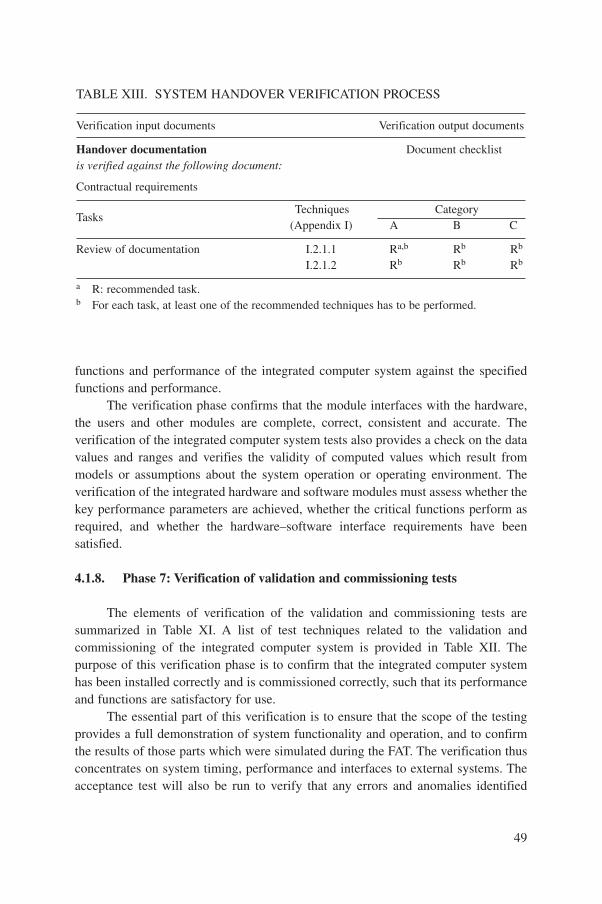
functions and performance of the integrated computer system against the specifiedfunctions and performance.
The verification phase confirms that the module interfaces with the hardware,the users and other modules are complete, correct, consistent and accurate. Theverification of the integrated computer system tests also provides a check on the datavalues and ranges and verifies the validity of computed values which result frommodels or assumptions about the system operation or operating environment. Theverification of the integrated hardware and software modules must assess whether thekey performance parameters are achieved, whether the critical functions perform asrequired, and whether the hardware–software interface requirements have beensatisfied.
4.1.8. Phase 7: Verification of validation and commissioning tests
The elements of verification of the validation and commissioning tests aresummarized in Table XI. A list of test techniques related to the validation andcommissioning of the integrated computer system is provided in Table XII. Thepurpose of this verification phase is to confirm that the integrated computer systemhas been installed correctly and is commissioned correctly, such that its performanceand functions are satisfactory for use.
The essential part of this verification is to ensure that the scope of the testingprovides a full demonstration of system functionality and operation, and to confirmthe results of those parts which were simulated during the FAT. The verification thusconcentrates on system timing, performance and interfaces to external systems. Theacceptance test will also be run to verify that any errors and anomalies identified
49
TABLE XIII. SYSTEM HANDOVER VERIFICATION PROCESS
Verification input documents Verification output documents
Handover documentation Document checklistis verified against the following document:
Contractual requirements
TasksTechniques Category
(Appendix I) A B C
Review of documentation I.2.1.1 Ra,b Rb Rb
I.2.1.2 Rb Rb Rb
a R: recommended task.b For each task, at least one of the recommended techniques has to be performed.

during the system validation have been corrected. A review of the installation shouldbe conducted to ensure that the integrated computer system has been installedcorrectly and accurately executes the functions allocated to it. This will includeconfirmation of all parameters dependent on the site or the site conditions to ensurethat the initial values are correct.
4.1.9. Phase 8: Verification of system handover
The elements of system handover verification are summarized in Table XIII.The purpose of this verification phase is to determine whether all the documentationrequired for the operation and maintenance of the system is in place prior to thehandover. This will entail a systematic review of the documentation to verify that itincludes specific plant licensing and design basis documentation, engineeringspecifications and analysis, drawings and diagrams, vendor manuals and softwaredocumentation, test specifications and qualification test documentation. This reviewwill assess the technical approach and scope of the engineering documentation thatsupports the computer system installation.
4.1.10. Phase 9: Verification of operation, maintenance and modification
The verification of the operational use, maintenance and modification processescan be very complex. In its simplest form it can be assumed that no corrective oradaptive maintenance of the software has to be performed. In this case, theverification activity will be limited to the performance of periodic functional tests asdescribed in Section I.2.3.1 of Appendix I. Operational use will cover normaloperation as well as the replacement of defective parts and changes to the software.It is necessary to examine the impact of the required change against the originalrequirements. This will determine whether the corrective or adaptive maintenanceprocedures in place are sufficient. If so, verification will be confined to a check on thecontent of the operation and maintenance manuals. It should ensure that properprocedures with appropriate configuration controls are in place for performing taskssuch as checking the installed software, reinstalling the software and replacingprogrammable read-only memories (PROMs).
If use and maintenance require software changes to be made, then correctiveand adaptive maintenance procedures should be available. The verification processesshould show that use and maintenance procedures are complete and will allowsoftware changes to be performed in a traceable manner using a process that resultsin correct software. The corrective and adaptive maintenance change procedureswould normally adopt a life cycle and contain a series of verification steps similar tothose for new software. It is expected that these change procedures would require animpact assessment. Typically, this might examine the consequences of the change on
50
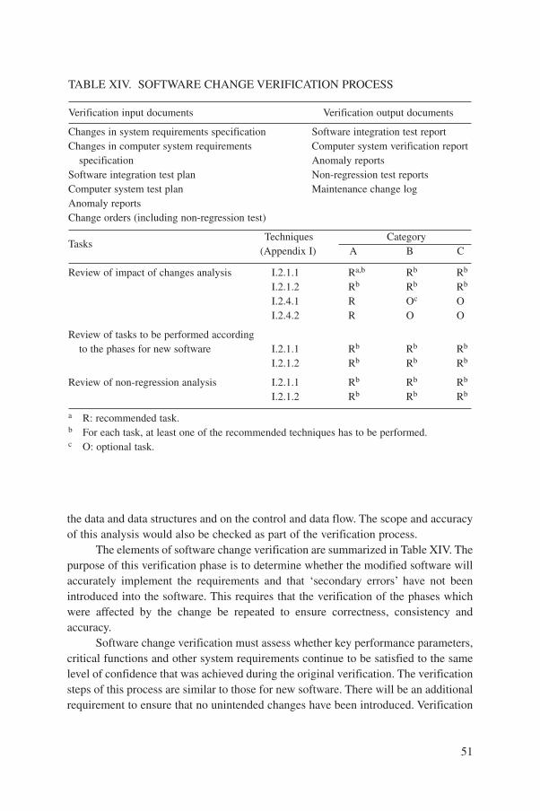
the data and data structures and on the control and data flow. The scope and accuracyof this analysis would also be checked as part of the verification process.
The elements of software change verification are summarized in Table XIV. Thepurpose of this verification phase is to determine whether the modified software willaccurately implement the requirements and that ‘secondary errors’ have not beenintroduced into the software. This requires that the verification of the phases whichwere affected by the change be repeated to ensure correctness, consistency andaccuracy.
Software change verification must assess whether key performance parameters,critical functions and other system requirements continue to be satisfied to the samelevel of confidence that was achieved during the original verification. The verificationsteps of this process are similar to those for new software. There will be an additionalrequirement to ensure that no unintended changes have been introduced. Verification
51
TABLE XIV. SOFTWARE CHANGE VERIFICATION PROCESS
Verification input documents Verification output documents
Changes in system requirements specification Software integration test reportChanges in computer system requirements Computer system verification report
specification Anomaly reportsSoftware integration test plan Non-regression test reportsComputer system test plan Maintenance change logAnomaly reportsChange orders (including non-regression test)
TasksTechniques Category
(Appendix I) A B C
Review of impact of changes analysis I.2.1.1 Ra,b Rb Rb
I.2.1.2 Rb Rb Rb
I.2.4.1 R Oc OI.2.4.2 R O O
Review of tasks to be performed accordingto the phases for new software I.2.1.1 Rb Rb Rb
I.2.1.2 Rb Rb Rb
Review of non-regression analysis I.2.1.1 Rb Rb Rb
I.2.1.2 Rb Rb Rb
a R: recommended task.b For each task, at least one of the recommended techniques has to be performed.c O: optional task.

may therefore involve regression testing of the system. One additional verificationtask is to ensure that all the anomalies identified in the original documentation havebeen cleared.
4.2. EXISTING ACCESSIBLE SOFTWARE
Software reuse is introduced in Section 2.2.2. The process of evaluation andassessment is described in the first supplement to IEC 880 [11], and includesverification activities and evaluation of feedback of experience. Before verificationfor reuse is possible, the user or application developer must have access to a large partof the documentation which describes both the development and the previousapplication of the software. The verification serves two distinct purposes. The firstpurpose is to ensure that the functionality and performance claimed for the systemand existing software correspond to the documented information. The second purposeis to ensure that the mapping of software functions is performed correctly from thesoftware proposed onto an arrangement which meets the new requirements. This mayrequire full V&V as part of an adaptive maintenance procedure.
Verification of the claimed functionality and performance will require use andreview of the existing documentation, in the same way as has been described for newsoftware. In this case, the development life cycle for new software will be followedand previous verification reports will be used. If anomalies are found, these will berecorded, rather than being resolved immediately in the normal development lifecycle. It would be expected that the anomalies would be cleared, for example as partof the maintenance process, as software changes.
The elements of software change verification are summarized in Table XIV andare discussed in Section 4.1.10. The verification of any change process will follow amaintenance life cycle.
4.3. EXISTING PROPRIETARY SOFTWARE
The reuse of existing proprietary software is discussed in Section 2.2.3. It isconsidered unlikely that reuse of proprietary software will be possible for category Asystems, since the owner of the software may not permit access to the documentationwhich describes the development and past application of the software. The process ofevaluation and assessment is described in the first supplement to IEC 880 [11], andincludes verification activities. It is likely to stress evaluation of feedback ofexperience.
A prerequisite for using existing proprietary software is verification based onavailable documentation and system requirements. The verification process serves
52

two distinct purposes. The first is to ensure that the functionality and performanceclaimed for the system and the existing software correspond to the documentedinformation. The second purpose is to ensure that the mapping of software functionsis performed correctly from the software proposed onto an arrangement which meetsthe new requirements.
The available documentation will be used to review the product against therequirements in much the same way as described for the documentation of newsoftware. The application of verification to existing proprietary software within thesoftware development phases defined in Section 3.2 is shown in Fig. 5. Thisproduction life cycle can be followed for existing proprietary software and anyexisting verification reports will be used. For the verification of proprietary software,more emphasis must be put on additional black box testing and statistical techniquesto establish the acceptability for use in category B and C applications.
53
TABLE XV. CONFIGURABLE SOFTWARE: ADDITIONAL VERIFICATIONS
Verification input documents Verification output documents
In addition to verification according to new software, Verification reportconfigurable software
is verified against the following documents:
Applicable documents according to new software
TasksTechniques Category
(Appendix I) A B C
Assessment of data requirements (phase 3) I.2.1.1 Ra,b Rb Rb
I.2.1.2 Rb Rb Rb
I.2.1.3 Rb Oc O
Review of database structure (phase 4) I.2.1.1 Rb Rb Rb
I.2.1.2 Rb Rb Rb
I.2.1.3 O O O
Review of data completeness, correctnessand accuracy (phase 4) I.2.1.1 Rb Rb Rb
I.2.1.2 Rb Rb Rb
I.2.3.2 O O O
a R: recommended task.b For each task, at least one of the recommended techniques has to be performed.c O: optional task.
4.4. CONFIGURABLE SOFTWARE
Configurable software is normally a combination of basic software and anapplication specific extension. The basic software can be treated as new or existingsoftware, with either accessible or proprietary documentation. For these cases, theverification process of Section 4.1, 4.2 or 4.3 is applied. In many cases, the basicsoftware has already been verified for some other application. It is then necessary toreview the verification and decide whether it was of acceptable rigour for theapplication.
The application specific extension can be treated as new software. It can consistof either configuration data or code, and each should be appropriately verified andvalidated. If the modules of the basic software have been modified for the application,they should be verified as new software to the best extent possible.
If the application part of the configurable software is treated as new softwarethe process outlined in Section 4.1 should be followed. Since the application part ofthe configurable software may consist of data, additional V&V activities for this aresummarized in Table XV and described below.
4.5. DATA VERIFICATION
Experience indicates that data verification should be repeated at least twice:
— During the data identification phase, comparing the intermediate databasegenerated by the data identification activities with the project data sources. Theintermediate database should be shown to be correct and then used as asecondary source.
— During the production of final data for loading, comparing them with thesecondary source.
It is a clear advantage if the data for loading can be directly inspected. Printoutswith suitable QA are needed. VDU inspection methods can be used.
The use of automatic error trap software is of great value and such traps shouldbe used throughout the verification process. Checks that may be carried out on thedata include those for the following:
— Completeness;— Consistency;— Range;— Implied rules: for example,
• Naming conventions,
54
• Abbreviations,• Information order.
Full exploitation of automated checks is possible only if the source data havebeen put into a master project database. Potential differences between differentsections of the database include differences in drawing or document issue level anddifferences of time of data entry from project sources and drawings. These will becritical in achieving satisfactory data. If the tool is used too early in the project time-scale, very many unnecessary or misleading errors will be found owing to inadequatesources of information. Effective methods of referring discrepancies for resolution bythe plant design and engineering organization are essential.
4.6. CATEGORY B AND C SYSTEM VERIFICATION
Many category B and C systems use proprietary software, often withconfiguration data to define input signals, control algorithms, VDU display designsand record contents. The verification for category B and C systems may use a lessrigorous process than that described for category A systems. This is due to the lowerimportance to safety. The relaxation of rigour in verification can be counterbalancedby more extensive historical evidence of production and installation than is usuallyavailable for category A systems. The availability of this evidence determines thepermissible reduction in rigour of verification for a given confidence in integrity.Good evidence permits greater confidence to be placed in the quality of the products.Sufficient verification may include only simple peer review of the software designdocuments, with simple testing on a functional basis. The use of path test coveragemetrics, code analysis or other more advanced methods is not normally needed.
Typical examples of category B and C functions are:
— Closed loop control of the reactor power or flux;— Closed loop control of reactor temperatures, especially where reactivity is
affected;— Display of alarms;— Display of event history;— Records for diagnosis.
4.6.1. Category B and C requirements and design verification
The requirements for a category B or C system are seldom as rigorous or formalas those for a category A system. Considerable freedom may be allowed to a supplier
55

in developing a VDU display system or in providing control functions from a standardlibrary. A two way process of agreement of requirements and of development of theVDU display designs or of the presentation methods for control algorithms isfrequently followed. This allows for the use of standard packages of software fromthe supplier.
The documents given to the software supplier to define the requirements willconsist of project design drawings and descriptions for the mechanical, electrical andother equipment. These documents should be reviewed and agreed by the supplier.The initial process of verification may be a review of the documents by the supplier’sorganization, to confirm their suitability, to clarify the requirements and to return anydiscrepancies or obvious errors for resolution by the project management.
The design verification of these requirements is important, as discussed inSection 1.4.1, but is outside the scope of this publication. In many category B or Csystems, these requirements are presented to the supplier or developed by the supplieras configuration information, VDU layouts and signal lists, or as code in a simpleapplication language, as discussed in Sections 2.2.4 and 3.4.
The documentation may therefore be in the form of lists of configurationconstants, tables and control diagrams showing the interconnections and signal flow,rather than any time based flow of operations and information. Verification planningmust ensure that this documentation exists and is suitable for manual and automaticchecking processes.
The process of establishing the VDU display designs for a project is complexand requires care and planning. Several hundred displays may be involved, whichmust accurately reflect the plant design and instrumentation, the agreed namingconventions and the groups of operations needed. The designs should be verified byreference to the operating staff of the end user and by review by human factorsspecialists.
4.6.2. Category B and C implementation verification
The development of applications software requires the preparation of manydetailed documents. Depending on the project management arrangements, these maybe the responsibility of the project or of the software system supplier. The projectquality plan should define these documents, the responsibility for originating themand the need for review or verification of each document or listing.
Review of the software output documents (such as listings of configuration dataand signal interconnections) is desirable for category B and C systems, either as aninternal supplier verification or as a review by the customer. Methods of verificationare discussed in Sections 3.4.2 and 4.5.
Independent verification of code for category B or C systems may not benecessary if there is sufficient confidence in system maturity, with proven capability,
56
and in the reliability of the compilation tools used. Any verification needed should beidentified in a V&V plan, and developed as a verification document for theapplication requirements.
Where a system is dependent on extensive configuration data, and the data areautomatically produced by tools operating on a database, the capability and reliabilityof the tools must be demonstrated. This is discussed in Section 5.5
5. VALIDATION
Validation is performed after the system integration phase and before thesystem is put into service. If any subsequent changes are made to the software, thenrevalidation would be required before the system is returned to service.
Validation can be broken down into a number of tasks, outlined in general termsbelow. The elements of validation are summarized in Table XVI. A list of testtechniques related to validation is provided in Table XII.
The purpose of validation is to demonstrate that the integrated system ofhardware and software correctly executes the functions defined in the systemrequirements specification. This requires testing of the integrated computer system todetermine that the system performs all specified functions completely, correctly,consistently and accurately. During the validation process, the interfaces with theother systems and with users are evaluated with respect to completeness, correctness,consistency and accuracy. Validation must assess whether the key performanceparameters, critical functions and other system requirements have been achieved, andmust demonstrate that the system fulfils the system requirements specification.
For validation to be fully effective, its scope must be clearly defined. Validationis based on the system requirements specification. Part of the validation of a safetysystem can be the validation of the actions of the safety functions of the system, asclaimed in the safety justification. This will involve a demonstration that each safetyaction is performed correctly and that the functionality is still available in anacceptable manner for all anticipated abnormal conditions. These should includesensor, equipment and actuator failure, failure of communications and operationduring maintenance and testing activities.
General descriptions of the validation activities are given in Sections 3.1.7 and3.1.8, and of their verification in Sections 4.1.7 and 4.1.8. Normally, these validationactivities are done by means of planned FATs and SATs, with appropriate reports ofthe testing done and anomalies found. The system test plans and their verification arediscussed in Sections 3.1.3 and 4.1.3, respectively.
57

5.1. NEW SOFTWARE
5.1.1. Validation process
The validation process is based on the requirements of the complete system. Itis therefore not dependent on the means of development of the system which containsthe software. Traditionally, validation has begun from the system requirements
58
TABLE XVI. INTEGRATED SYSTEM VALIDATION PROCESS
Validation input documents Validation output documents
Integrated system System validation reportAcceptance test reportAnomaly report
is validated against the following documents:
System requirements specificationFactory acceptance test procedures
TasksTechniques Category
(Appendix I) A B C
Review of test coverage I.2.1.1 Ra,b Rb Rb
I.2.1.2 Rb Rb Rb
Review of validation test results I.2.1.1 Rb Rb Rb
I.2.1.2 Rb Rb Rb
Review of anomaly records I.2.1.1 Rb Rb Rb
I.2.1.2 Rb Rb Rb
Review of verification documentation I.2.1.1 Rb Rb Rb
I.2.1.2 Rb Rb Rb
Review of operation andmaintenance records I.2.1.1 Rb Rb Rb
I.2.1.2 Rb Rb Rb
Review of system documentation I.2.1.1 Rb Rb Rb
I.2.1.2 Rb Rb Rb
Review of traceability records/matrix I.2.1.1 Rb Rb Rb
I.2.1.2 Rb Rb Rb
a R: recommended task.b For each task, at least one of the recommended techniques has to be performed.
specification. Experience has shown that failures of software in critical systems canoften be traced back to errors in the system requirements specification (Section 1.4.1).Notwithstanding this, the computer system validation activities considered here canonly take the system requirements as input, and a validation activity can only provideany degree of confidence in the system performance from this starting point.
The documents taken as input to the validation process include:
— System requirements specification;— Computer system requirements specification;— Validation test plan;— Validation test procedures;— Validation test design;— Validation test cases.
Static and dynamic simulations of input signals can be arranged to operate thecomputer system in modes which represent normal operation, anticipated operationaloccurrences and accident conditions which require system action. For reactorprotection systems, each function should be confirmed by conducting a representativetest for the actions caused by each parameter for trip or protection, singly and incombination. The validation test design should therefore define the required inputsignals with their sequences and values. The validation test cases must describe theanticipated output signals with their sequences and values and the signal levelacceptance criteria. Additional requirements for validation include verification thatthe proposed test coverage includes all functions. This should be confirmed by adocumented trace to the requirements specification (Section 1.4.2).
These tests should also demonstrate any features of the computer system thatare claimed in the safety justification.
5.1.2. Output documents
The output from validation will be two documents:
— System validation report;— Anomaly report.
The results of the computer system validation are given in the computer systemvalidation report, which should summarize the following:
— Hardware and software tested;— Equipment used to complete the tests;— Equipment calibration status;
59
— Simulation model used;— Functions tested;— Discrepancies found.
The system validation report should state either that the software has passedvalidation or that it has failed, and give the reasons for failure. As with the verificationreports, the validation report should not advise on how the problems could beovercome, and should not indicate preferred solutions. In addition, as part ofvalidation, it will be necessary to make an assessment of and to record the testcoverage. Validation should check that all the requirements have been covered bythe tests. These should include functions, timing performance and abnormalconditions.
The anomaly report documents generated during validation should record eachanomaly detected and give the following information:
— Description and location of the anomaly;— Impact;— Apparent cause of the anomaly and nature of the error;— Criticality of the fault;— Recommendations for action.
Each anomaly should be resolved satisfactorily before validation can formallybe completed.
5.2. EXISTING ACCESSIBLE SOFTWARE
Validation of existing accessible software will involve the same steps as for newsoftware, to the extent that the documentation is available. If any changes arerequired, these should be made using adaptive maintenance procedures, which wouldrequire a repeat of validation for the affected parts of the software. Thus, if there werea change to the basic requirements, the whole cycle would be followed, withverification of all phases. A change in the data describing the configuration wouldpossibly only require verification of the integration phase. Validation would takeplace after these steps.
To allow validation of existing software, it should meet the followingrequirements:
— The existing software was developed according to good software engineeringpractice, following a QA plan developed in accordance with recognizedstandards, such as IEEE Std 830, IEEE Std 1012 and IEC 880 [4, 7, 16];
60

— A documented history exists, demonstrating reliable operation;— An accurate user manual exists.
If source code and object code are not accessible, then the followingdocumentation should be analysed:
— Functional specifications;— Interface specification;— Design documents;— Test files.
The analysis should check the use of interrupts, memory allocation andrecursion. Suitable tests should be defined to show that these features operatecorrectly. Checks of the error handling resources and of self-tests (such as those ofmemory stacks) are needed. Validation testing of the complete system, including theexisting accessible software, should be done as described earlier in Section 5.
5.3. EXISTING PROPRIETARY SOFTWARE
The validation process for systems using existing proprietary software cannotnormally make use of:
— Verification documents, produced during development of the proprietary software;— Source code documentation;— Software requirements for the proprietary software.
In consequence, the validation of the end products must be based on the verifiedsystem requirements specification.
Operational history over a suitable period should be evaluated for theconfidence possible in the performance of the proprietary software and in itssuitability for use within the proposed system.
The operational history should include:
— History of release;— Number of licensees and extent of use;— History of errors and modifications to correct defects (fixes).
On the basis of the operational history, additional validation testing should bedefined where doubt or lack of confidence exists. Validation testing of the completesystem, including the existing proprietary software, should be done as describedearlier in Section 5.
61
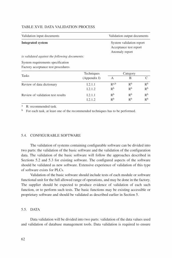
5.4. CONFIGURABLE SOFTWARE
The validation of systems containing configurable software can be divided intotwo parts: the validation of the basic software and the validation of the configurationdata. The validation of the basic software will follow the approaches described inSections 5.2 and 5.3 for existing software. The configured aspects of the softwareshould be validated as new software. Extensive experience of validation of this typeof software exists for PLCs.
Validation of the basic software should include tests of each module or softwarefunctional unit for the full allowed range of operations, and may be done in the factory.The supplier should be expected to produce evidence of validation of each suchfunction, or to perform such tests. The basic functions may be existing accessible orproprietary software and should be validated as described earlier in Section 5.
5.5. DATA
Data validation will be divided into two parts: validation of the data values usedand validation of database management tools. Data validation is required to ensure
62
TABLE XVII. DATA VALIDATION PROCESS
Validation input documents Validation output documents
Integrated system System validation reportAcceptance test reportAnomaly report
is validated against the following documents:
System requirements specificationFactory acceptance test procedures
TasksTechniques Category
(Appendix I) A B C
Review of data dictionary I.2.1.1 Ra,b Rb Rb
I.2.1.2 Rb Rb Rb
Review of validation test results I.2.1.1 Rb Rb Rb
I.2.1.2 Rb Rb Rb
a R: recommended task.b For each task, at least one of the recommended techniques has to be performed.
that the data items used are correct and will subsequently generate the correctfunctionality for the system.
5.5.1. Data validation
The elements of validation of data are summarized in Table XVII. The purposeof data validation is to ensure that each item of data in the system in its operating stateis correct for the requirements. The validation process for data may take many forms,some of which may be automated with considerable gains in efficiency. This may bedone by processing the primary plant database used by the project to generate testinformation and to provide reference lists in the form of test plans.
Validation of data requires testing to show that input signals are assigned to thecorrect computer inputs, with the correct hardware, and with correct softwarecharacteristics, alarms, signal titles and display features. The correct actions must beshown to be taken for control switches or soft controls, with the correct output actuationdrive hardware, and with correct software assignments of control function and logic.
Site acceptance testing is normally combined with plant connection of sensorsand control outputs, with standard written tests for each class of signal. A typicalnuclear plant may involve many thousands of such signals, with a requirement tovalidate several characteristics of each signal. Therefore, careful QA and rapidmethods of resolution of anomalies are needed.
The validation of data can exploit the use of test platforms off-site to reducepressure on on-site activities. This will allow testing of much of the configuration andfunctionality information in FATs.
5.5.2. Validation of database management tools
IEC 880 recommends the use of automatic tools for data management, butrecommends that the tools be thoroughly and appropriately tested [4]. Other referencedocuments require that validated tools be selected for the necessary integrity level.The basic principle is that if a tool is used to produce code or information whichcannot be otherwise verified and validated, then it must meet the full technical, QA,verification and validation requirements of the application.
It is essential that the use of automatic handling of data during all possiblestages not be discouraged by unrealistic requirements for tool validation. Experienceindicates that data recorded and produced automatically using a database, andchecked by automatic error trappers, are more accurate and more dependable thanmanually produced data.
The tools used must be assessed carefully. For system data important to safety,the appropriateness of the tools and processes used should be justified in a document.Guidance is given in the supplement to IEC 880 [11].
63

5.6. VALIDATION OF CATEGORY B AND C SYSTEMS
Application of the most rigorous requirements of IEC 880 is not usuallyexpected for category B and C systems. However, the most important tasks ofvalidation of category A systems may be carried out for category B and C systems.This should include extensive functional testing; qualification is required by IAEASafety Guide 50-SG-D8 (Section 4.4) and will necessitate such testing [15].
The level of independent management and validation planning required forcategory A systems need not apply to category B and C systems. It is recommendedthat validation be carried out with the systems installed on-site, so that it is subject torepresentative environmental and plant conditions. Some validation requirementsmay be less demanding for category B and C systems, and feedback of experience isvery important as a quality indicator.
Validation is normally considered to be the most important part of the processof V&V for category B and C systems. Validation tests should be generated from thesystem requirements to demonstrate that the system will function as specified. Animportant part of validation of many category B and C systems is data validation,described earlier.
The validation tests may also include those states identified as potentialhardware failure modes, or ambiguous, out-of-range, inconsistent or incorrect inputs.A methodology for identification of such states and a recommendation for validationtesting to resolve them are given in outline in IEEE Std 7-4.3.2-1993 as“Identification and resolution of abnormal conditions and events (ACE)” [17]. Themethod can result in testing which shows that the system does not do things it is notsupposed to do. This has frequently been required by site commissioning engineers,and such testing is sometimes referred to by them as ‘negative testing’.
It is also good practice for validation to be used as part of the customeracceptance process, and therefore for the documents to be provided for review by theend user. Validation test reports are normally produced as part of the FAT and SATprocess and for the plant commissioning records.
6. LICENSING
Countries constructing and operating nuclear power plants and other facilitiesare expected to establish a regulatory body, whose duties include the enforcement ofapplicable regulations and of the terms of licences [18]. The approach to licensing orregulation differs between countries because of their different legislative backgroundsand engineering practices. The activities and actions of the licensing authority,
64

including the relationship with the licensee, are therefore governed by the regulatoryframework that exists in a particular country.
Licensing activities range from strict and thorough reviews and inspections ofall available material, in order to establish confidence in the design and developmentprocesses, to a minimum of reviewing activity, depending on the safety role of thesystem and the national regulatory practice.
The responsibility for the safe operation of the nuclear plant rests with thelicensee. This responsibility includes the safe implementation of software basedsystems, whether designed directly by the licensee or by an outside designorganization. The role and responsibilities of the licensee and outside designorganization in the software life cycle should be defined in detail to allow for this.
Licensing is in part a matter of confidence between the licensing authority andlicensee. Generating confidence is a complex process, and confidence will be based onexperience, culture, legislation, tradition and other social factors. These factors implythat the licensing requirements cannot be defined in an exact way in any internationalguideline or standard. Generally, a series of safety documents must be prepared for theregulator, including documents which give details of the V&V done and which justifythe performance and safety of the system. Relevant recommendations for V&V can begiven only to cover available tools and methods, together with their benefits anddrawbacks. Information of this type is given in this publication and the reader mustjudge its suitability in relation to specific licensing needs.
The licensing authority should consider the overall arrangements by which thelicensee and the relevant suppliers intend to implement and maintain the softwarebased system. These include the licensee’s and supplier’s QA arrangements andV&V programme and the application of technical standards for safety criticalsoftware. In addition, the licensing authority may choose to select specific areas ofinterest for in-depth review. It is important not to lose the safety perspective in thelicensing process. The safety significance of the areas selected for in-depth reviewneeds to be considered by the licensing authority.
Licensing cannot be exclusively based on reviews, inspections or test activities.Licensing must also involve confidence in methods and quality. It will involve theapplication of QA standards or guidelines, such as ISO 9000, IEEE Std 730 andIAEA TRS 282, and of standards for the development and design of software basedsystems, such as IEC 880 [3, 4, 9, 10, 19]. The licensing authority must also haveconfidence in the licensee and the ability of the relevant supplier to use and toimplement the methods outlined in standards and guidelines. Methods used to buildup the necessary confidence may include audits, inspections and reviews.
It is beneficial for both the licensing authority and the licensee, andconsequently to the supplier and licensee, to reach an understanding on:
— What development methods are to be used;
65

— What approach and methods the licensing authority will use for assurance ofthe correct use and implementation of the methods.
This understanding should be established before the development and designactivities begin.
The licensing authority should be able to evaluate the results of reviews andinspections. This evaluation can be undertaken by the licensing authority alone orwith support from independent experts.
The review process should include consideration of independent assessments(third party reviews) performed on the software. This could include the application ofinspection and analysis techniques identified in Appendix I. For example, codeinspection, static analysis, tool validation and dynamic testing could all be applied ona sample basis. Consideration of the appropriate time to apply the independentassessments is required. For example, the application of static analysis followingcompletion of the manufacturer’s V&V processes could be used to build confidencein the delivered software.
7. CONCLUSIONS
The main conclusions of this publication are given below. They are not in anyorder of importance.
(1) Verification and validation are two different processes with different endobjectives that make use of different techniques. The two processes arecomplementary and the confidence in the final software product will bedependent on the effectiveness of both processes.
(2) There is no single definitive method for application and completion of theprocesses of verification and validation of software and computer systems. Themethods adopted for V&V will depend on both the processes and the productand therefore they should be selected on a case by case basis.
(3) Verification is needed to check that the inputs to and the outputs from each stepof the development process correspond correctly. Verification of the softwaredevelopment steps is usually undertaken from documentation. For example, ina conventional development, the design documents are checked against thespecification to provide assurance that the original requirements are reflectedaccurately in the software design and therefore will permit successfulrepresentation in the software code.
(4) Validation is necessary to confirm the software performance and functionalityby tests against the system requirements specification. Validation provides
66

assurance that the integrated system performs in the manner required. Validationprocesses typically include extensive testing and review of the intermediateand final products generated during the development and verification.
(5) The amount of V&V performed can be varied according to the importance tosafety of the computer based system. The highest level of assurance isnecessary for category A safety system applications. Lower levels of assurancecan be accepted for category B and C applications.
(6) Category A applications require that V&V be conducted by a team which isindependent of the development team and whose competence is at leastequivalent to that of the development team. This can be achieved by arrangingthat the management of the V&V team be independent of that for thedevelopment team, in accordance with IEC 880, sections 6.2.1 and 8 [4]. Theseteams can also be subject to external review.
(7) Category B and C applications may also require independent V&V. The teamcompleting the V&V should be independent of the development team. Whilestaff may be members of both teams and so undertake both development andverification activities, self-verification should not be permitted. The rigour ofthe V&V measures will usually be less than that applied for category A systems,although the same tools and techniques as for category A can be used.
(8) The development of new software should follow a recognized life cycle withwell defined phases, inputs and outputs. The verification of the outputs againstthe inputs should be planned into the process at the start of the development andinclude suitable hold points and reviews. The nature of the verification intendedshould be defined and agreed before the process is started.
(9) The production of a new system based on the reuse of existing software requiresdifferent practices to be followed. If the complete documentation is available,then a life cycle similar to that for corrective maintenance of new software canbe followed. Although all changed items will be verified, this may be only apartial verification of the system. This partial verification has to be supportedby appropriate evidence provided during the complete system development andby an impact analysis to assess the consequences of the changes.
(10) When existing proprietary software is used, where the documentation is notalways available, only limited V&V will be possible. The evaluation of feedbackof operating experience is important, and guidance is being prepared for this inthe first supplement to IEC 880 [11]. The limited verification may consist ofextensive testing to confirm that the system requirements specification is beingmet. This is essentially validation rather than verification. It is very unlikelythat software reused in this manner could be included in a category A system.
(11) Some forms of software are configurable, and are made ready for use bysupplying data or preparing statements in an application specific language. Inthis case, verification has two parts, that of the basic software and that of the
67

data or application language. The verification of the basic software should havebeen completed beforehand, while the second part of the verification concernsthe new information. When an application specific language is used, the newsoftware life cycle should be applicable. Verification of data requires differenttechniques such as reference to the original plant design documents and theproject master lists of information.
(12) Category B and C applications often use some specially written applicationsoftware and extensive existing system software. The V&V for such systemsshould follow the recommendations given in this publication. It should thuscontain a check on the accuracy of the design against the requirements, theaccuracy of the implementation against the design, and the performance andfunctionality of the integrated system compared with the requirements. This canbe achieved for the specially written software by using the methods and toolsdescribed in this publication. The V&V of the existing software should alreadyhave been completed and recorded by the software supplier. The acceptance ofthe system will be dependent on the assessment of these records, forcompliance with appropriate international and national standards and forcompliance with project requirements. This assessment should be supported byextensive validation, which must include testing.
(13) If existing software is used, the system will also normally require applicationsoftware, which may be automatically generated. Current methods of softwaregeneration allow extensive systems to be built from existing software modules,often by configuration using graphical methods and database tools. Suchsoftware requires V&V of the software building material and of the softwaretools used. Tools are typically used for preparation of the requirements and theirtranslation into the application information, configuration data or code. If thevalidity of these tools can be accepted, then the V&V of the application canoften be simplified. For example, it may be sufficient to undertake a systematicconfirmation that the configuration data are correct and correspond to theinformation in the source documents. These sources describe the plantcharacteristics, signals, output actuators and actions.
(14) Suppliers of commercial grade process control and protection equipmentnormally will modify their basic software continuously to add extra featuresand to make corrections. If this type of equipment is qualified for use in aparticular application, then care must be taken to ensure that neither theapplication nor the system software is changed during the period of service.This requires that strict configuration control be applied to ensure that anyreplacement or additional unit contains the same version of system softwarethat was qualified for use.
(15) The use of software tools for the preparation of requirements, their translationinto code, the assessment of code and the preparation of configuration
68

information for computer based systems is a topic whose full discussion isbeyond the scope of this report. IEC subcommittee SC45A is producing toolrequirements in the first supplement to IEC 880 [11]. One relevant principlewhich has been identified is that if a tool is used to produce code or informationwhich cannot be otherwise verified and validated, then it must meet the fulltechnical, QA, verification and validation requirements of the application. Toavoid the complexity of applying such a stringent requirement, the output oftools should be simple to verify against the source information. It has beenfound in practice therefore that tool output should generally be printable, eitherdirectly or after simple translation, and the prepared tool output for any loadingto a target machine should be able to be inspected by the use of a VDU display.
(16) Nuclear plants are making increasing use of VDUs for the presentation ofinformation to the plant operators. The V&V of such information is oftencomplex, and depends on the concurrent verification and validation of the plantsignals, and in some cases of the plant output actuators and control roomswitches. A very large quantity of information must be verified and shown to becorrect. For example, the total data might be 20 000 signals, sometimes with tenor more characteristics each, and 400–500 detailed display layouts. Verificationmust be followed by validation to show that the installed signal transmitters andplant arrangements are correctly reflected in the system. In this situation, verycareful administration must be employed, and must be able to handle the largevolume of data and record the potentially large number of defects in theconfiguration.
69
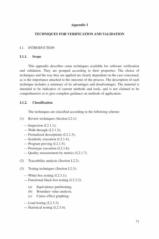
71
Appendix I
TECHNIQUES FOR VERIFICATION AND VALIDATION
I.1. INTRODUCTION
I.1.1. Scope
This appendix describes some techniques available for software verificationand validation. They are grouped according to their properties. The choice oftechniques and the way they are applied are clearly dependent on the case concerned,as is the importance attached to the outcome of the process. The description of eachtechnique includes a summary of its advantages and disadvantages. The material isintended to be indicative of current methods and tools, and is not claimed to becomprehensive or to give complete guidance on methods of application.
I.1.2. Classification
The techniques are classified according to the following scheme:
(1) Review techniques (Section I.2.1):
— Inspection (I.2.1.1);— Walk-through (I.2.1.2);— Formalized descriptions (I.2.1.3);— Symbolic execution (I.2.1.4);— Program proving (I.2.1.5);— Prototype execution (I.2.1.6);— Quality measurement by metrics (I.2.1.7).
(2) Traceability analysis (Section I.2.2).
(3) Testing techniques (Section I.2.3):
— White box testing (I.2.3.1);— Functional black box testing (I.2.3.2):
(a) Equivalence partitioning,(b) Boundary value analysis,(c) Cause–effect graphing;
— Load testing (I.2.3.3);— Statistical testing (I.2.3.4);
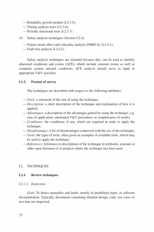
— Reliability growth models (I.2.3.5);— Timing analysis tests (I.2.3.6);— Periodic functional tests (I.2.3.7).
(4) Safety analysis techniques (Section I.2.4):
— Failure mode effect and criticality analysis (FMECA) (I.2.4.1);— Fault tree analysis (I.2.4.2).
Safety analysis techniques are included because they can be used to identifyabnormal conditions and events (ACE), which include external events as well ascomputer system internal conditions. ACE analysis should serve as input toappropriate V&V activities.
I.1.3. Format of survey
The techniques are described with respect to the following attributes:
— Goal: a statement of the aim of using the technique;— Description: a short description of the technique and explanation of how it is
applied;— Advantages: a description of the advantages gained by using the technique, e.g.
ease of application, automated V&V procedures or completeness of results;— Conditions: the conditions, if any, which are required in order to apply the
technique;— Disadvantages: a list of disadvantages connected with the use of the technique;— Tools: the types of tools, often given as examples of available tools, which may
be used to apply the technique;— References: references to descriptions of the technique in textbooks, journals or
other open literature or to projects where the technique has been used.
I.2. TECHNIQUES
I.2.1. Review techniques
I.2.1.1. Inspection
Goal: To detect anomalies and faults, mostly of predefined types, in softwaredocumentation. Typically, documents containing detailed design, code, test cases ortest data are inspected.
72

Description: The inspection consists of checks of a document or a set ofdocuments by one or more persons. These people form a team of limited size, incharge of detecting anomalies and faults of specified types. The possible types ofanomalies and faults are related to the method or technique used to develop thedocuments and to the nature of the document. These anomaly and fault types couldbe related to non-functional requirements such as dependability, safety or security.The fault types are limited to a defined set. The inspection is carried out infour steps:
(1) The documents are distributed. They should preferably be of the same kind.The documents should be chosen to provide a global view of one activity (either allthe documents of one phase or a representative sample). The readers should bechosen, on the basis of their experience, for effective anomaly and fault detection.They should have a comparable background to the authors of the documents. At leasttwo but not more than four readers are recommended.
(2) A specified period is left for reading the documents and issue of comments.The inspection itself consists of reading the documents and checking against predefinedanomaly and fault types. Usually, the set of anomaly and fault types is provided to thereaders as a checklist. Each reader provides comments using a standard form. Thecomments are characterized according to the kind of anomaly and fault detected.
(3) A meeting is organized to analyse the comments and to determine theirstatus and the need for corrections. The meeting is attended by all the readers. It mayalso be attended by the author or a representative of the team responsible for thedocuments. The meeting may be chaired by a moderator to balance decisions betweenthe author and the readers. During the meeting, comments are classified and theirrelevance is discussed, i.e. whether an anomaly or error really exists and whether it isof a predefined type. Suppression of duplicate comments can be anticipated. Eachanomaly and fault classed as genuine leads to a correction request. Responsibilitiesare identified for the correction of the documents and for the verification that all thecorrections are made
(4) The documents are corrected and verification is performed to ensure that allthe requested corrections have been taken into account. The responsibility forverifying the modifications and the corrections is generally assigned to a member ofthe inspection team. Time-scales for these actions should be set. Typically, the wholeprocess takes less than two weeks and the meeting is ideally restricted to two hours.The meeting report should include in addition to the date and attendee list:
— The references to the input documents;— A record of the checklists used by the readers, if any;— A list of the minor comments, the associated suggestions and the deadline for
corrections;
73
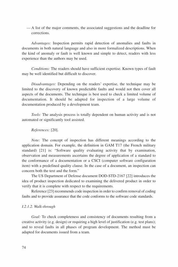
— A list of the major comments, the associated suggestions and the deadline forcorrections.
Advantages: Inspection permits rapid detection of anomalies and faults indocuments in both natural language and also in more formalized descriptions. Whenthe kind of anomaly or fault is well known and simple to detect, readers with lessexperience than the authors may be used.
Conditions: The readers should have sufficient expertise. Known types of faultmay be well identified but difficult to discover.
Disadvantages: Depending on the readers’ expertise, the technique may belimited to the discovery of known predictable faults and would not then cover allaspects of the documents. The technique is best used to check a limited volume ofdocumentation. It should be adapted for inspection of a large volume ofdocumentation produced by a development team.
Tools: The analysis process is totally dependent on human activity and is notautomated or significantly tool assisted.
References: [20].
Note: The concept of inspection has different meanings according to theapplication domain. For example, the definition in GAM T17 (the French militarystandard) [21] is: “Software quality evaluating activity that by examination,observation and measurements ascertains the degree of application of a standard tothe conformance of a documentation or a CSCI (computer software configurationitem) with a predefined quality clause. In the case of a document, an inspection canconcern both the text and the form.”
The US Department of Defense document DOD-STD-2167 [22] introduces theidea of product inspection dedicated to examining the delivered product in order toverify that it is complete with respect to the requirements.
Reference [23] recommends code inspection in order to confirm removal of codingfaults and to provide assurance that the code conforms to the software code standards.
I.2.1.2. Walk-through
Goal: To check completeness and consistency of documents resulting from acreative activity (e.g. design) or requiring a high level of justification (e.g. test plans);and to reveal faults in all phases of program development. The method must beadapted for documents issued from a team.
74
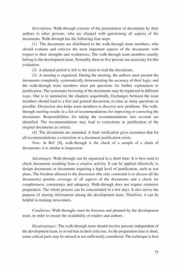
Description: Walk-through consists of the presentation of documents by theirauthors to other persons, who are charged with questioning all aspects of thedocuments. Walk-through has the following four steps:
(1) The documents are distributed to the walk-through team members, whoshould evaluate and criticize the most important aspects of the documents withrespect to their strengths and weaknesses. The walk-through team members usuallybelong to the development team. Normally, three to five persons are necessary for thisevaluation.
(2) A planned period is left to the team to read the documents.(3) A meeting is organized. During the meeting, the authors must present the
documents completely, systematically demonstrating the accuracy of their logic, andthe walk-through team members must put questions for further explanation orjustification. The systematic browsing of the documents may be organized in differentways. One is to summarize the chapters sequentially. Exchanges between the teammembers should lead to a free and general discussion, to raise as many questions aspossible. Discussion also helps team members to discover new problems. The walk-through meeting results in a list of recommendations for improving or correcting thedocuments. Responsibilities for taking the recommendations into account areidentified. The recommendations may lead to corrections or justification of theoriginal documents as correct.
(4) The documents are amended. A final verification gives assurance that forall recommendations a correction or a document justification exists.
Note: In Ref. [8], walk-through is the check of a sample of a chain ofdocuments; it is similar to inspection.
Advantages: Walk-through can be organized in a short time. It is best used tocheck documents resulting from a creative activity. It can be applied effectively todesign documents or documents requiring a high level of justification, such as testplans. The freedom allowed to the discussion (the only constraint is to discuss all thedocuments) permits coverage of all aspects of the documents and a check forcompleteness, consistency and adequacy. Walk-through does not require extensivepreparation. The whole process can be concentrated in a few days. It also serves thepurpose of sharing information among the development team. Therefore, it can behelpful in training newcomers.
Conditions: Walk-throughs must be foreseen and planned by the developmentteam, in order to ensure the availability of readers and authors.
Disadvantages: The walk-through team should involve persons independent ofthe development team, to avoid bias in their criticism. As the preparation time is short,some critical parts may be missed or not sufficiently considered. The technique is best
75

used to check documents issued by a single author, and it should be adapted to tackledocuments issued by a team.
Tools: The process is totally dependent on human activity. It requires in-depthunderstanding of the document and of the author’s explanations and justifications. Itis not automated or tool assisted.
References: [8, 24].
I.2.1.3. Formalized descriptions
Goal: To produce a complete, unambiguous requirements description and/orspecification that can be used as a starting point for V&V activities.
Description: The term ‘formalized description’ is used for techniques providinga well defined notation (syntax) and model (semantics) suitable for expressing someaspects of the specification or design of software.‘Formalized’ indicates here that thereasoning and manipulations which are used have some mathematical basis. In somecases the degree of formalism allows, in principle, the generation and discharge of allproof conditions needed to show that the description is complete and correct.
Formalized techniques include:
— Use of modern real time languages such as ADA and OCCAM.— Application oriented graphical languages, with a fully defined notation (syntax)
of functional elements each of which has a precisely defined semantics;examples include instrumentation and control function diagrams.
— General graphical languages with a formally defined semantics; examplesinclude Petri nets and graphical data flow languages.
— Methods based on logic and algebra, including real time temporal logics,algebraic or axiomatic approaches and assertional calculus.
Advantages: The specification can be demonstrated to be both complete andconsistent according to the properties offered by the language. Properties of thespecification can be derived and checked against the requirements for correctness,including both written requirements and requirements as perceived by the systemdesigners and plant operators.
The completed specification forms the basis for code verification using staticanalysis techniques. The specification can also be used as the starting point forcontinuation of the development using a formalized design method which subjects thesteps of refinement to formal proof. The application of a formalized method, even ifthe proof aspects are not considered, quickly reveals missing information because of
76
the systematic approach to specifying the functions. Formalized description is aprerequisite for automatic code generation.
Conditions: A high level executable language must be available which haselements able to express precisely the kinds of problems to be solved. For example,the Vienna development method (VDM) is valuable for model based systemdescriptions but not always helpful for time based problems, where temporal methodssuch as the concurrent calculus system (CCS) are more valuable.
Disadvantages: Many of the methods require the specifier and validator to havesome knowledge of the language used. The resulting system description is usually noteasily intelligible to the traditional system engineer or software designer.
Tools: Examples of tools include:— Development tools based on ADA and OCCAM;— CAD tools for PLC programming;— ASA+™, SAGA™, SPACE™ (specification and coding environment);— For VDM: SPECBOX™, MURAL™, compilers’ synchronous language tools.
References: [25–30].
I.2.1.4. Symbolic execution
Goal: To show, mathematically, the agreement between the source code and thespecification, and to identify the relationships between output and input variables.
Description: The program is ‘executed’ by replacing the left hand side by theright hand side in all assignments. Conditional branches and loops are translated intoBoolean expressions. As a result, the output variables are expressed as algebraic orlogic functions of the input variables.
Advantages: No input data are needed. The results can be used in programproving.
Conditions: Formal specifications (with assertions) are necessary to check theresults. Tool support is a necessity for all but the simplest programs.
Disadvantages: The algebraic expressions which result are often difficult tointerpret. It can be difficult to analyse loops with a variable number of iterations. Formany programs, the number of possible symbolic expressions is prohibitively large.The method is unlikely to detect missing paths.
77
Tools: MALPAS™, SPADE™.
References: [31, 32].
I.2.1.5. Program proving
Goal: To provide a basis for comparison with the program specification.
Description: Assertions are made at various locations in the program, which areused as pre- and post-conditions to various paths through the program. The proofconsists of two parts. The first involves showing that the program transfers the pre-conditions into the post-conditions according to a set of logical rules defining thesemantics of the programming language, provided that the program actuallyterminates (i.e. reaches its proper conclusions). The second part is to demonstrate thatthe program does indeed terminate (e.g. does not go into an infinite loop). Both partsmay need inductive arguments. The result is the demonstration of the correctness ofthe program with respect to the assertions.
The method can be used together with program walk-through or inspection. Atthe present time, it is recommended only for the most critical of programs.
Advantages: A rigorous statement on correctness is achievable.
Conditions: Assertions must be determined and written into the program. Thiscan be ensured if a suitable constructive development technique is used, such as thatdescribed in Ref. [33].
Disadvantages: Requires highly skilled and specialized personnel.
Tools: MURAL™.
References: [33].
I.2.1.6. Prototype execution
Goal: To check the feasibility of implementing the system against givenconstraints; and to communicate the specifier’s interpretation of the system to thecustomer, in order to locate misunderstandings.
Description: A subset of system functions, constraints and performancerequirements is selected. A prototype is built, using high level tools if possible. At thisstage, constraints such as target computer, implementation language, program size,
78
maintainability and reliability need not be considered. The prototype is evaluatedagainst the customer’s chosen criteria and the system requirements may be modifiedin the light of this evaluation.
Advantages: The customer has a chance to assess the system at a very earlystage and to verify the requirements and the understanding of the requirements.Resources are not wasted by building the wrong system.
Conditions: No special conditions.
Disadvantages: A significant amount of resources is required.
Tools: Development tools, and especially those supporting formal methods (e.g.SMALLTALK™).
References: [34].
I.2.1.7. Quality measurement by metrics
Goal: To predict the attributes of programs from properties of the softwareitself rather than from its development or test history.
Description: Techniques using metrics are used to evaluate some measurableproperties of software, e.g. complexity, and to relate them to quality factors, e.g.reliability. Software tools are required to evaluate most of the measures. Some of themetrics which can be applied are given below:
— Graph theoretic complexity: this measure is based on the complexity of theprogram control graph, represented by its cyclomatic number.
— Number of ways to actuate a certain module (accessibility): the more a moduleis accessed, the more likely it is to be debugged.
— Software science: this measure computes the program length by counting thenumber of operators and operands; it provides a measure of complexity andestimates development resources.
— Number of entries and exits per module: minimizing the number of entry/exitpoints is a key feature of structured design and programming techniques.
In general, this technique is used on the source code. Moreover, if formalizedlanguages are used, this technique can also be used at the level of design orspecification.
Advantages: Some characteristics of the code structure can be verified withoutany execution of the code.
79
Conditions: The source code, and preferably the design or specification,correctly identified, must be available.
Disadvantages: As the correct relationship between measurable items (metrics)and high level attributes is still a matter of research and may change from applicationto application, this information may be misleading.
Tools: Static analysers are available as off the shelf products, e.g.LOGISCOPE™, QUALMS™, MALPAS™, CONCERTO AUDIT™, MacCabe’sTools™.
References: [31, 35–37].
I.2.2. Traceability analysis
Goal: To verify that the input requirements of an activity have beenexhaustively taken into account by checking their trace in the resultingdocumentation; and to verify that all critical requirements have been identified andincluded through the development life cycle, i.e. from requirements analysis to finaltests.
Description: Traceability analysis consists of identifying the inputrequirements and confirming how they have been taken into account by checking thetarget documents. For example, the analysis might check the system requirementdocumentation translation into the software requirement documentation, or thesoftware requirement documentation into the software performance specification, thesystem requirement documentation into test files, etc.
Traceability analysis may be carried out by a single person. It requires an in-depth understanding of the input requirements and also of the method or techniqueused to develop the target documentation. When necessary, traceability analysis mayinvolve a step to confirm the requirements in order to be certain to trace the actualrequirements and not merely chapters or paragraphs of the input documentation.
A knowledge of specific probabilistic reliability allocation techniques may benecessary to carry out the traceability analysis of reliability requirements, andsimilar expertise may also be needed for other non-functional requirements. Theanalysis results in a document justifying that all the requirements have been takeninto account properly. The document will identify, requirement by requirement,which part or component, or chapter of the documentation, fulfils it. The results areusually summarized in the form of a matrix of input requirements versus elementsof the target documentation. The matrix can also be extended to include thesource code.
80

Advantages: Traceability analysis confirms the links between the documentsand, if applied during development, strengthens those links.
Conditions: A person must be available with a deep understanding of therequirements and of the way the target documents have been developed. Traceabilityanalysis is made easier if the input requirements can be simply referred to withoutambiguity. Some predefined rules should be followed; for example, one requirementper sentence or numbering of requirements allows a simple trace reference method.
Disadvantages: Traceability analysis is easier to apply for functionalrequirements. Non-functional requirements, such as safety, security andmaintainability requirements, are less simple. These may be fulfilled by a certainstructure or by a co-operative behaviour of the components. For these, the traceabilitymatrix may often usefully be accompanied by a case by case justification.
Tools: Establishing the links is a process which is driven by human activities,which cannot be automated. However, tools exist which are able to capture both inputdocuments and target documents and traceability links between them. It may beassumed that other tools can also be used, e.g. hypertext and electronicdocumentation tools.
References: [38].
Note: Traceability analysis is best used in the earliest phases of thedevelopment, e.g. software requirements traceability analysis and software designtraceability analysis [7], but can also be used at any phase to verify that criticalrequirements have been taken into account.
I.2.3. Testing techniques
I.2.3.1. White box testing
Goal: To find program bugs, referring them to corresponding parts of thespecification; and to check systematically that all corresponding requirements aremet, and that there is no unreachable source code.
Description: The chosen part of the program is executed together with a testdata set. This must be chosen from a global test data set which refers to the relevantsection of the design specification or is provided by automated test data setgeneration. Appropriate test sets should be chosen to detect program faults
81
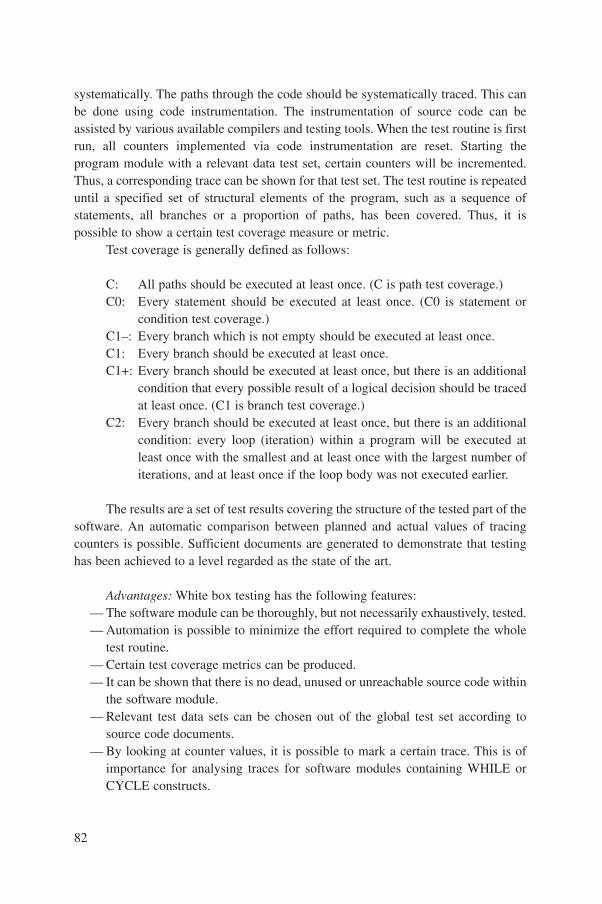
systematically. The paths through the code should be systematically traced. This canbe done using code instrumentation. The instrumentation of source code can beassisted by various available compilers and testing tools. When the test routine is firstrun, all counters implemented via code instrumentation are reset. Starting theprogram module with a relevant data test set, certain counters will be incremented.Thus, a corresponding trace can be shown for that test set. The test routine is repeateduntil a specified set of structural elements of the program, such as a sequence ofstatements, all branches or a proportion of paths, has been covered. Thus, it ispossible to show a certain test coverage measure or metric.
Test coverage is generally defined as follows:
C: All paths should be executed at least once. (C is path test coverage.)C0: Every statement should be executed at least once. (C0 is statement or
condition test coverage.)C1–: Every branch which is not empty should be executed at least once.C1: Every branch should be executed at least once. C1+: Every branch should be executed at least once, but there is an additional
condition that every possible result of a logical decision should be tracedat least once. (C1 is branch test coverage.)
C2: Every branch should be executed at least once, but there is an additionalcondition: every loop (iteration) within a program will be executed atleast once with the smallest and at least once with the largest number ofiterations, and at least once if the loop body was not executed earlier.
The results are a set of test results covering the structure of the tested part of thesoftware. An automatic comparison between planned and actual values of tracingcounters is possible. Sufficient documents are generated to demonstrate that testinghas been achieved to a level regarded as the state of the art.
Advantages: White box testing has the following features:— The software module can be thoroughly, but not necessarily exhaustively, tested.— Automation is possible to minimize the effort required to complete the whole
test routine.— Certain test coverage metrics can be produced.— It can be shown that there is no dead, unused or unreachable source code within
the software module.— Relevant test data sets can be chosen out of the global test set according to
source code documents.— By looking at counter values, it is possible to mark a certain trace. This is of
importance for analysing traces for software modules containing WHILE orCYCLE constructs.
82
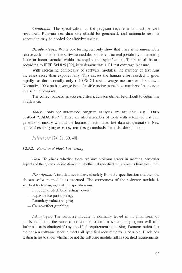
Conditions: The specification of the program requirements must be wellstructured. Relevant test data sets should be generated, and automatic test setgeneration may be needed for effective testing.
Disadvantages: White box testing can only show that there is no unreachablesource code hidden in the software module, but there is no real possibility of detectingfaults or inconsistencies within the requirement specification. The state of the art,according to IEEE Std 829 [39], is to demonstrate a C1 test coverage measure.
With increasing complexity of software modules, the number of test runsincreases more than exponentially. This causes the human effort needed to growrapidly, so that normally only a 100% C1 test coverage measure can be shown.Normally, 100% path coverage is not feasible owing to the huge number of paths evenin a simple program.
The correct outputs, as success criteria, can sometimes be difficult to determinein advance.
Tools: Tools for automated program analysis are available, e.g. LDRATestbed™, ADA Test™. There are also a number of tools with automatic test datagenerators, mostly without the feature of automated test data set generation. Newapproaches applying expert system design methods are under development.
References: [24, 31, 39, 40].
I.2.3.2. Functional black box testing
Goal: To check whether there are any program errors in meeting particularaspects of the given specification and whether all specified requirements have been met.
Description: A test data set is derived solely from the specification and then thechosen software module is executed. The correctness of the software module isverified by testing against the specification.
Functional black box testing covers:— Equivalence partitioning;— Boundary value analysis;— Cause–effect graphing.
Advantages: The software module is normally tested in its final form onhardware that is the same as or similar to that in which the program will run.Information is obtained if any specified requirement is missing. Demonstration thatthe chosen software module meets all specified requirements is possible. Black boxtesting helps to show whether or not the software module fulfils specified requirements.
83
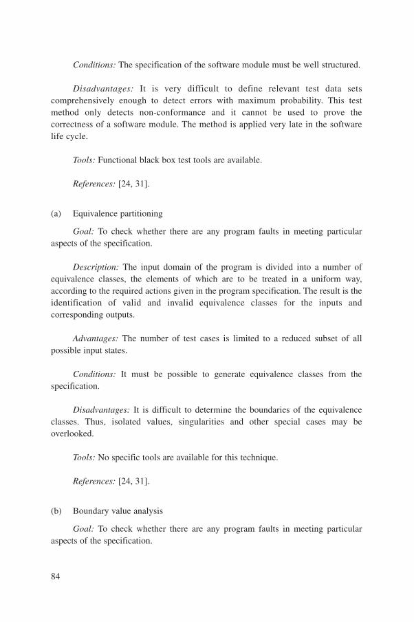
Conditions: The specification of the software module must be well structured.
Disadvantages: It is very difficult to define relevant test data setscomprehensively enough to detect errors with maximum probability. This testmethod only detects non-conformance and it cannot be used to prove thecorrectness of a software module. The method is applied very late in the softwarelife cycle.
Tools: Functional black box test tools are available.
References: [24, 31].
(a) Equivalence partitioning
Goal: To check whether there are any program faults in meeting particularaspects of the specification.
Description: The input domain of the program is divided into a number ofequivalence classes, the elements of which are to be treated in a uniform way,according to the required actions given in the program specification. The result is theidentification of valid and invalid equivalence classes for the inputs andcorresponding outputs.
Advantages: The number of test cases is limited to a reduced subset of allpossible input states.
Conditions: It must be possible to generate equivalence classes from thespecification.
Disadvantages: It is difficult to determine the boundaries of the equivalenceclasses. Thus, isolated values, singularities and other special cases may beoverlooked.
Tools: No specific tools are available for this technique.
References: [24, 31].
(b) Boundary value analysis
Goal: To check whether there are any program faults in meeting particularaspects of the specification.
84
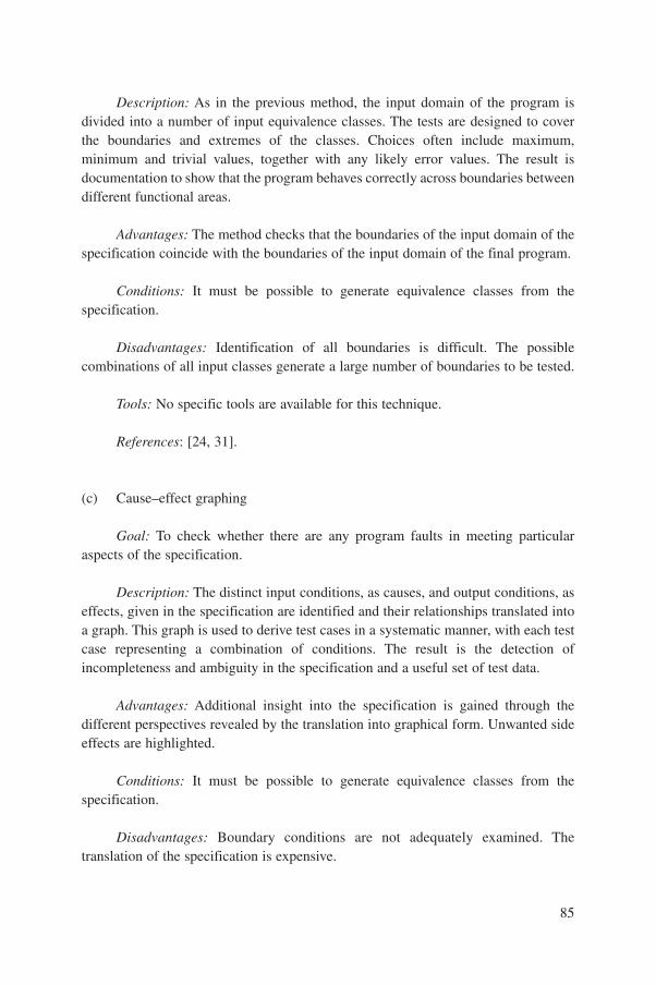
Description: As in the previous method, the input domain of the program isdivided into a number of input equivalence classes. The tests are designed to coverthe boundaries and extremes of the classes. Choices often include maximum,minimum and trivial values, together with any likely error values. The result isdocumentation to show that the program behaves correctly across boundaries betweendifferent functional areas.
Advantages: The method checks that the boundaries of the input domain of thespecification coincide with the boundaries of the input domain of the final program.
Conditions: It must be possible to generate equivalence classes from thespecification.
Disadvantages: Identification of all boundaries is difficult. The possiblecombinations of all input classes generate a large number of boundaries to be tested.
Tools: No specific tools are available for this technique.
References: [24, 31].
(c) Cause–effect graphing
Goal: To check whether there are any program faults in meeting particularaspects of the specification.
Description: The distinct input conditions, as causes, and output conditions, aseffects, given in the specification are identified and their relationships translated intoa graph. This graph is used to derive test cases in a systematic manner, with each testcase representing a combination of conditions. The result is the detection ofincompleteness and ambiguity in the specification and a useful set of test data.
Advantages: Additional insight into the specification is gained through thedifferent perspectives revealed by the translation into graphical form. Unwanted sideeffects are highlighted.
Conditions: It must be possible to generate equivalence classes from thespecification.
Disadvantages: Boundary conditions are not adequately examined. Thetranslation of the specification is expensive.
85

Tools: Some tools to automate the generation of test data from the graph areavailable.
References: [24, 31].
I.2.3.3. Load testing
Goal: To verify that the system will meet requirements to handle bursts of inputsignals or of messages, and to guarantee that specified response times are met.
Description: In systems sensitive to high load conditions due to bursts of inputsignals, e.g. caused by a plant transient or trip, load tests are performed to verify theability to handle the input load according to the specification.
Load testing is based on the assessed worst case load of the system or itsmessage transfer systems. In order to make the test realistic, it is important to analysethe number of status changes or of messages transmitted, relating them to time asaccurately as possible, and margins should be specified.
For example, a trip might be tested by simulation of 500 status changesduring the first minute, 200 in the second minute and 50 in the third minute afteran initiating event. Far higher numbers for longer periods have been experiencedin some plants. A test harness able to inject up to 1000 status changes per minute,with random timing, for 5 minutes, could allow suitable performance tests with amargin.
The burst of input status changes is simulated by devices which allow alterationof the number of status changes over the test period. Simulated operator actions anddemands for displays may be included in the test. Message transfer systems shouldsimulate transfer of many messages, with random timings and lengths, and withfailure conditions such that the expected bandwidth limits are approached.
During tests of this type, the following key parameters can be measured ormonitored:
— CPU load;— Backlog in event recording;— Number and identity of events not recorded or messages not transferred;— Time delay for output action as a result of status change;— Download of events to presentation devices, e.g. VDUs or alarm panels;— Recovery parameters.
Advantages: This type of test is the only one that is able to verify thatsystems sensitive to bursts of input signals or demands are able to handle theincreased load.
86
Conditions: Performance data must be specified in advance. The worst case ofinput load must be defined and a simulator designed which is able to generate theinput load required.
Disadvantages: No disadvantages are known.
Tools: Input signal or message generators (simulators) are needed.
References: [41].
I.2.3.4. Statistical testing
Goal: To derive reliability figures on the final program performance.
Description: Statistical tests are tests of a program or a software module withtest data selected with a statistical distribution of the input space of the object to betested. The statistical distribution may be derived from:
— Information about the input space in the specific application;— Assumptions about the fault distribution in the object to be tested;— Assumptions about the frequency with which the different parts of the input
space will be exercised.In the case of protection system software, this technique requires extensive
input from the possible trip scenarios to determine the portion of input space ofrelevance and the frequency with which its various conditions might be experienced.
The evaluation of statistical tests can be restricted to determine the probabilityof a correct response by simply monitoring the outputs of the object to be tested.Automated test harnesses have been found valuable for this. Side effects should beconfirmed to be acceptable, such as:
— Unintended memory access;— Unintended change of data in other software products;— Wind-up of stack;— Excessive processing time.
These effects must be investigated fully and shown to be acceptable using othermeans.
Advantages: Figures for correct response frequency can be derived withoutdetailed knowledge of the operation of the object under test. The results can becombined with the output of other verification techniques.
Conditions: Each test run must be supervised so that every fault is detected. Acomplete specification is needed to derive the correct results to be expected from the
87
system under test. The number of tests must be large so that the results are statisticallymeaningful, i.e. sufficiently large that the predicted probability of a failure falls belowa certain limit with a given level of confidence. Other test techniques should be usedbefore this technique is applied, so that the number of errors detected during thetesting is at a very low level.
Disadvantages: The number of test data scenarios required is potentially verylarge. Consequently, the production of the test data and the evaluation of the correctresults become an enormous and demanding task. The effort to establish the part ofthe input space to be tested and the distribution of test data is also very large. Forsafety critical software, this technique can be used only to supplement other methods.
Tools: No specific tools.
References: [4, 17, 40].
I.2.3.5. Reliability growth models
Goal: To derive a reliability figure on the basis of recorded fault data.
Description: All software errors detected during debugging, testing andoperation are logged. A reliability growth model is selected and the parameters in itsfailure probability density function are determined on the basis of this information.The results can be the probability density function of faulty execution, the expectednumber of remaining errors or the mean time to the next failure, etc., depending onthe model used.
Advantages: If there is detailed knowledge of the test object and itscorresponding failure probability density function, then only a moderate effort isrequired for this technique.
Conditions: Error data must be stored during all phases of the life cycle.
Disadvantages: An essential problem is to determine a relevant failureprobability density function that will be significant to the test object. The results ofthis technique are directly influenced by the choice of failure probability densityfunctions. This test method should not be used alone for V&V activities for safetycritical software. The method is unlikely to be of use for safety critical applications.If a statistically meaningful number of errors were found, there would be someconcern about the suitability of the software and development method.
88

Tools: City University (London) tool package.
References: [42].
I.2.3.6. Timing analysis tests
Goal: To prove that a software module or task meets specified time constraints.A safety critical command message must be generated correctly and meet given timeconstraints on when it is generated. This may be described by the term timeliness.
Description: Real time systems are characterized by reliability andpredictability. So, for event driven systems, requirement specifications must beproved to be met. To complete this, run time instrumentation is required for thedynamics of run time behaviour. In some cases it may be possible to measure thesystem response directly, e.g. by the time delay between signal input and output,using simple measurement methods. Recently, more complex tools have beendeveloped.
Advantages: Dynamic testing has the following features:— Monitoring of system operation;— Flexible management of primitive events (e.g. single alarms) based on on-line
monitoring and maximal target system independence;— High performance, fully distributed event recognition;— Object oriented monitor programming language;— Flexible data analysis and visualization capabilities.
Conditions: One of the timing analysis test methods is based on events andintervals monitored by a versatile timing analyser (VTA). To specify events andintervals, an event definition language was developed and is available for dynamicvalidation purposes. Thus, a detailed analysis at run time can be made in order toprove that the whole system will meet all time constraints. The test equipment isconnected via an Ethernet deterministic local area network (LAN) with the completehardware and software system. Different analyses and statistics can then be producedto check whether all system reactions meet the appropriate time constraints.
This method requires use of Ethernet IEEE 802.3 D (deterministic Ethernet,developed by the Institut national de recherche d’informatique et d’automatique inFrance), a VME bus system and a closely specified target CPU.
Disadvantages: This technique is very time consuming and it is usually notpossible to demonstrate that the worst case has been identified. Dynamic analysis ofreal time systems requires run time instrumentation. The instrumentation causes the
89

implementation of certain patches in the source code to be analysed without stoppingthe task. In order to minimize delay times caused by the implemented ‘probes’ in thetarget software, three possible sizes of patches are provided: one at a minimal size,implementing a MOVE statement only, one at a small size to record one parameter,and one at a maximum size to record a certain number of parameters connected witha certain event. Depending on the CPU hardware chosen, the effective delay timescaused by certain patches can be calculated.
Tools: VTA, combined hardware–software system, and object oriented eventdefinition language (GOLDMINE).
References: [43].
I.2.3.7. Periodic functional tests
Goal: To ensure that the tested system is capable of performing its designfunction. The IAEA Safety Guide 50-SG-D8 [15] requires that safety related digitalcomputer systems be designed for testing during the lifetime of the plant. Periodictests can be performed automatically or manually.
Description: Periodic functional tests are part of the overall monitoring of itemsimportant to safety. All systems important to safety must have arrangements thatpermit test and calibration at intervals based on the equipment function, expectedcalibration drift, failure rate and other time dependent characteristics as well as on thereliability requirements.
Periodic functional tests are normally performed as black box tests. If possible,on-line or built-in test facilities should be included in the design. If the on-line testdetects an error, the system must go to a fail-safe state and give an alarm.
A functional test of a computer system important to safety must, as a minimum,consist of one or more of the following activities:
— Inject test signals of an appropriate magnitude to give a suitable actuation ofoutputs or readouts, as required;
— Test automatically calculated set points or variables to verify responses to eachinput variable;
— Test the status and operability of interlocks, bypasses, test indications andannunciation circuits;
— Monitor the appropriate parameters during the test.Tests should be overlapping, implying that the whole chain from sensor to
actuator is tested.
90

Advantages: If implemented in the system design, periodic tests allow testingof the on-line system.
Conditions: The computer system must be tested under closely definedconditions corresponding to those in which it is expected to fulfil its intendedfunctions. However, during testing, the configuration of the system can be changed inorder to isolate the computer system from the rest of the system or to connect it to atest loop. After the test, the original configuration of the system must be restored.Periodic functional tests should be performed as on-line tests.
Disadvantages: Design faults and common cause faults are normally notdetected by periodic functional tests.
Tools: Black box testing tools.
References: [4, 44–46].
I.2.4. Safety analysis techniques
I.2.4.1. Failure mode effect and criticality analysis
Goal: To verify that the system can meet, on a continuing basis, the specifiedsafety requirements as stated in the system requirements specification. Failure modeeffect and criticality analysis (FMECA) should be performed at appropriate stages inthe design of the safety systems to be effective.
Description: To complete an FMECA, the consequences of each failure typemust be analysed. Information gathered includes failure description, causes, defects,detection means, resultant safety consequences or other hazards, and recoverymethods and conditions.
The principal procedure of FMECA can be described as follows:— All possible random or common cause failures and their consequences are
identified;— All identified failures relevant to safety must either lead to a fail-safe system
state or trigger alarm functions;— The effect on shared supporting systems of a short circuit or a fire must be
identified;— The effect of failures in supporting systems must be identified and evaluated.
The failure analysis can be performed during or after the writing of the systemrequirements specification.
91
Advantages: This technique can identify potentially dangerous components.
Conditions: The documentation describing the design of the analysed part ofthe system must be available. Compliance with the requirements for independencemust be established. The failure analysis must be performed by a team having theappropriate expertise.
Disadvantages: The technique may require considerable effort.
Tools: FMECA™, SOFIA™, RELIASEP™ and, dedicated to software:AIDL™, CECILIA™, FIABILOG™, MSI-REALITY™.
References: [14, 15, 47, 48].
I.2.4.2. Fault tree analysis
Goal: To identify conditions leading to a significant consequence (hazard) witha significant probability of occurrence. The probability can be quantified or estimatedin a qualitative manner.
Description: Beginning with a system hazard, the analysis identifies or makesa hypothesis for the immediate and proximal causes, and describes the combinationof environment and events that preceded the hazard, usually in the form of a directedgraph or an ‘AND/OR tree’. It is often accompanied by an ‘event tree analysis’showing relevant event propagation information.
Advantages: The method is well known in safety analysis. Consequently, avariety of tools are available.
Conditions: The causes and consequences of an event must be identified andthere must be data available on event probability.
Disadvantages: Fault trees and event trees are often very large. Temporal(dynamic) aspects are hardly ever treated. The method was developed for hardwaresystems; adaptation to software must be handled with care. Establishing the baseevents and the probability of outcomes can be problematic and become subjectiverather than objective.
Tools: PHANISS™, Fault Tree™, Risk Spectrum™.
References: [49, 50].
92
Appendix II
SINGLE FAILURE CRITERION
II.1. INTRODUCTION
The single failure criterion is a term commonly used in a deterministicapproach to ensure that a system will be available and operate when a demand isplaced on it. It refers to a principle that safety functions shall be still possible if asingle failure occurs. It specifies a simple design requirement for a certain minimumredundancy of a system or a group of equipment.
In the IAEA Code 50-C-D (Rev. 1), Section 329 [13], the single failure criterionis defined as follows: “An assembly of equipment satisfies the single failure criterionif it is able to meet its purpose despite a single random failure assumed to occuranywhere in the assembly. Consequential failures resulting from the assumed singlefailure are considered to be an integral part of the single failure.”
The Code requires the single failure criterion to be applied to each safety groupincorporated in the plant design which performs all actions required for a particularpostulated initiating event (PIE) (Section 330). A method to test compliance isoutlined in the Code. As the Code does not give details of the interpretation of thecriterion, the IAEA has published a Safety Practice on Application of the SingleFailure Criterion [45]. Although the Safety Practice does not deal expressly with theapplication of the single failure criterion to computer systems, it does give practicalexamples of its implementation for certain safety requirements.
The design of a nuclear power plant is required to consider all identified PIEsand ensure that the required safety functions can be accomplished with acceptablereliability for each PIE.
To achieve a high degree of confidence that the safety functions will beperformed according to the Code, a number of measures are specified. In order toensure and maintain adequate reliability of each safety system and component, threerequirements must be satisfied:
(a) The independence of the safety system or component from the effect of the PIEmust be maintained.
(b) The probability of failure of the components of the safety system must beminimized by adopting high quality standards and engineering practices fordesign, construction, operation and maintenance.
(c) The design of the safety system must be tolerant of failures without loss of theability to perform the safety function.
93
II.2. APPLICATION OF SINGLE FAILURE CRITERION TO SYSTEMSIMPORTANT TO SAFETY
The single failure criterion is applicable to each safety group. A safety groupis an assembly of equipment which performs all actions required for a particularPIE, in order that the limits specified in the design basis for that event are notexceeded. If a computer system is an active part of a safety group for which thesingle failure criterion is applicable, the criterion is also applicable to the computersystem.
For the single failure criterion, two aspects must be considered:
(a) The single failure criterion is a basic safety principle and as such should be partof the overall system requirements. The single failure criterion will influencethe design with respect to redundancy, independence, fail-safe design andauxiliary support. The ability of the design to fulfil the criterion must beverified after the system requirements specification phase.
(b) Implicit in the application of the single failure criterion is the requirement fortestability of the system and components to which this criterion is applied.Otherwise undetected failures must also be taken into account.
One important aspect to be considered is that application of the single failurecriterion only provides tolerance of single random failures. The occurrence of randomfailures is overcome by redundancy. However, redundancy achieved by means ofidentical channels may be defeated by common cause failures. Therefore, commoncause failure analysis must be carried out in addition to analysis to show compliancewith the single failure criterion.
Software faults do not normally result in random failures in service. They aredue to errors in the design and implementation process. The result of such an error isa software fault, which may be challenged by system conditions or signal trajectories(which may appear in a random way), and then results in a system failure. Softwarefaults should be detected and corrected during the development and V&V activities,before the system is put into service. An undetected software fault can result incoincident failure of two or more redundant channels which provide a safety function.This will occur if similar signal conditions or trajectories affect all channels and areincorrectly processed owing to the common fault. Analysis and tests related to thesingle failure criterion alone will, for these reasons, not be able to detect systemsensitivity to software faults.
By definition, computer systems are active components. Active componentsmay have active failure modes as well as passive failure modes. For computersystems, no distinction is made in reliability analysis between active and passivefailures. A passive random failure is simply assumed to occur on demand and is
94
handled like an active failure. Active and passive failures may occur at any timeduring, shortly after or a long time after an accident.
Examples of random passive failures are given below:
— Limit value not changed in the database after a modification;— Circuits failed closed or open in response to outputs from the computer system.
An example of a random active failure is unintended output from the computersystem due to a faulty input signal.
Examples of random failures which can be either active or passive are asfollows:
— Hardware failure preventing the computer from performing its intendedfunctions (passive);
— Hardware failure causing the computer system to be actuated when notrequested (active).
The method most commonly used to detect random failures is testing, andbecause of this, safety systems are normally tested periodically. In-operation testmethods may also be used.
The reliability of a system not only depends on the degree of redundancy but isalso a matter of the test strategy. During testing, the configuration of the system isoften changed in order to isolate the computer system from the remainder of thesystem or to connect it to test circuits. After the test the original configuration of thesystem must be restored. Any of these operations may be the cause of faults,especially if such tests are done routinely. The system reliability analysis must allowfor such testing and for the potential for such faults to reduce the reliability of asystem very greatly by making it inoperable. The probability of unrevealed faultconditions must also be considered in reliability analysis. For this reason, optimal testintervals and procedures must be identified in relation to the operational possibilitiesand hazards.
Computer technology offers an advantage since, to a great extent, self-tests canbe performed. Self-testing can take place on-line and will not usually interfere withnormal operation of the safety system. This feature must be considered in the systemrequirements specification.
Periodic tests are normally performed as black box tests. The purpose of thesetests is to verify that different combinations of input signals will result in expectedreactions and outputs from the computer system.
95
Appendix III
EXPERIENCE
A number of countries have experience with the V&V of computer basedsystems for use in the safety and safety related systems of nuclear power plants. Thisappendix records, country by country, some of the experience gained in the V&V ofsoftware for nuclear systems, but is not intended to give a history of what hashappened. Each section has the same structure, as follows:
— The standards and practices currently in use are given;— The systems in use are identified;— The role and safety classification of the systems are described;— The verification and validation of the systems are discussed;— The anticipated direction of development of V&V practices are discussed.
III.1. CANADA
Since 1971, all CANDU type NPPs have used computers for reactor and plantcontrol, alarm annunciation, data display and logging. The basic elements ofverifying and validating these systems included reviews of requirements and designdocumentation, code walk-throughs, white box and black box testing using regressiontest data methods, dynamic plant simulations and system acceptance testing.Evolution of these non-safety-critical systems from the earlier to the more recentplants has occurred more in the planning of system development and verification, inthe scope and detail of documentation and in the introduction of independentvalidation than in the fundamental techniques.
The introduction of the use of computers for safety critical systems occurredin the early 1980s. Computer based systems were designed for process tripfunctions for the two safety shutdown systems. In the late 1980s, for theDarlington plant, the two shutdown systems were fully computerized, includingtrip logic, displays to the operator and computer aided testing. For the safetycritical trip logic, formal mathematics based verification techniques and reliabilitytesting were introduced.
Experience from verifying and validating the Darlington trip logicsystem has led to the development of a set of standards to form the basis forengineering and licensing software for safety critical and safety related nuclearapplications.
96

III.1.1. Standards and practices
Experience with software engineering for safety critical applications showedthat there is no generally agreed, measurable definition of acceptability for this typeof software within the technical community. Furthermore, there is no widely acceptedand adopted practice for the specification, design, verification and testing of safetycritical software. To provide a basis for licensing software for nuclear applications,Ontario Hydro and Atomic Energy of Canada Limited (AECL) have jointly developeda set of standards based on the principles of IEC 880 [4] and on the experience gainedin developing and licensing the Darlington plant shutdown systems and earliercomputer systems. The framework of standards includes:
— A guideline to categorize software with respect to its failure effects on nuclearsafety, with four categories defined, similar to IEC 1226 [6] but more quantitative;
— High level standards, independent of methodology, addressing the softwareengineering process for the three safety related categories;
— Sets of standards, procedures and guidelines which are dependent onmethodology, for specific activities within the engineering process for eachcategory;
— A guideline defining how to qualify predeveloped software.
The high level standards define the requirements for each stage of thedevelopment process from system requirements to final system integration andtesting. The requirements for verification at each development stage are specified.
The outputs from each development process must be reviewed to confirm thatthey comply with the requirements specified in the inputs to that process. Theseoutputs are written using mathematical functions. This is a requirement for safetycritical software. The outputs are systematically verified against the inputs usingmathematical verification techniques.
Typical V&V outputs for safety critical systems include reports on requirementsreview, design review, design verification, code review, code verification, hazardsanalysis, unit tests, subsystem tests, validation tests and reliability tests.
Quality attributes are specified for the outputs from each development stage,which provide a basis for verification review. These include completeness,correctness, consistency, verifiability, modifiability, modularity, structure, traceabilityand understandability. The specific attribute set which is used is dependent on thedevelopment stage.
These standards have been applied to software developed for safety criticalapplications for the Pickering plant and, in the Republic of Korea, for Wolsong 2, 3and 4. They are also being used for non-safety-critical backfit applications onBruce A.
97
III.1.2. Pickering digital trip meter (Ontario Hydro)
A digital trip meter, using an embedded microcontroller, has been developed tosolve operating problems with the existing analog meters used on the heat transporthigh temperature trip system.
A software development methodology which meets the high level standard forsafety critical software was used. This methodology is called the rational designprocess (RDP) and evolved from the techniques used on the Darlington computerizedshutdown systems. The required behaviour of the software is defined by mathematicalfunctions using notations with well defined syntax and semantics. The input/outputbehaviour is defined in tabular format.
The verification process, which was carried out by an independent team, includedreviews at each stage of development. System requirements, software requirements,software design and code stages were verified, with the reviews being based on thequality attributes defined in the standard. Systematic mathematical verification wasperformed between the software requirements and software design phases andbetween the software design and code development phases. A code hazard analysis wasdone from a bottom-up perspective to identify potential design weaknesses.
White box testing was carried out to verify code compliance with the designand the software requirements. Black box validation testing and a reliability testbased on 7000 randomly initiated input trajectories demonstrated compliance with thesystem functional and reliability requirements.
The trip meter was in the final stages of licensing review at the time ofpreparation of this publication. The development process proved effective inproducing reliable code, with no significant errors being identified by the verificationtesting and none by the validation and reliability tests.
III.1.3. Wolsong 2, 3 and 4 shutdown systems SDS1 and SDS2 (AECL)
Each of the two independent, triplicated reactor shutdown systems SDS1 andSDS2 uses computers to perform the logic for the process system trip parameters, lowand high primary heat transport pressure, low steam generator level, low flow, etc.These parameters have power dependent set points, which are adjusted by conditionsat low power.
SDS2 uses a microprocessor based system. An object oriented computerlanguage was used to produce the code using the RDP software development methoddescribed above.
SDS1 uses a process controller which embodies a graphical functional languagefor code generation. This graphical function notation was used to specify the softwarerequirements and design. The software development process using this graphicalfunction notation is called the integrated approach (IA). The notation is
98
mathematically precise but fairly easily understood. This facilitated formal review ofthe requirements and design by systems analysts and control engineers. A codedisassembler was developed to allow verification of the executable code against thedesign specification.
Code hazard analysis was carried out on both SDS1 and SDS2. No hazardswere identified, but some modifications were made to provide more resilience topotential hardware faults.
Verification testing against the software design description and softwarerequirements was done using both white box and black box testing. Testing revealedno significant errors in SDS2 and none in SDS1. About 30% of the total effort wasspent at the front end of the software development process, to provide assurance ofcompleteness of the system level specifications and their correct translation intosoftware requirements. It is considered that this was a direct contributor to ensuringthat few errors were identified at later stages. Use of the graphical functional languagefor SDS1 greatly simplified formal verification.
Reliability testing was done using 10 000 test profiles which were generated bya system simulator to cover all PIEs for which the systems provide protection. Eachtrajectory used randomly selected initial values. The test inputs were applied to boththe system under test and a validated test oracle. The results were comparedautomatically and discrepancies logged. Successful completion of the tests indicatedthat the target reliability was met to a confidence level of about 65%.
III.1.4. Future development
The current verification processes for safety critical software embody peerreviews and formal mathematical reviews during the specification, design and codegeneration phases. These are coupled with code verification testing during the codedevelopment phase. Validation testing and reliability testing confirm compliance withsystem requirements. Tools are used to help to generate the requirements documentand to design in a consistent and traceable fashion. This aids the ability to review, andtest case generators and test oracles reduce the testing effort. Further development isproceeding in these areas to improve the cost effectiveness of the V&V process, bothfor original code development and for subsequent maintenance. The development ofvalidated functional languages is another area which will simplify verification ofapplication code.
For lower safety categories, formal methods are not required. Verification iscarried out during the software development process, with reviews of requirementsand design documents coupled with code walk-throughs for control applications. Setsof deterministic test cases are developed for white box and black box testing and plantsimulations used to verify dynamic characteristics.
99
III.2. FRANCE
III.2.1. Standards and practices
The classification of I&C systems and equipment, including computerizedsystems, which is adopted by Electricité de France (EdF) for a given standardizedplant series, is defined by the French Society for Design and Construction Rules forNuclear Island Components (AFCEN) at the level of French codes. This classificationfollows National Fundamental Safety Rules based on IAEA Safety Guide 50-SG-D1[48]. For the N4 series, this categorization defines four classes: 1E, 2E, important tosafety but not classified (IPS-NC), and non-safety. Classes 1E, 2E and IPS-NC coversystems, equipment and software important to safety: 1E is the safety class, and 2Eand IPS-NC are the safety related classes.
The QA programme is based on the IAEA QA Code and Safety Guides [2].The AFCEN code, French Design and Construction Rules for Electrical
Equipment of Nuclear Islands, defines common applicable software engineering rulesfor software important to safety and availability of an NPP. For 1E software, this coderequires the application of IEC 880 [4].
Moreover, EdF also uses IEC 880 as a baseline for 2E software, theapplicability of its requirements depending on analysis of experience feedback whenavailable (e.g. for PLCs).
III.2.2. Systems in use
III.2.2.1. 1300 MW(e) series
Since the end of the 1970s, EdF has installed programmable systems for thecontrol and protection functions in the 20 nuclear units of the 1300 MW(e) PWRseries.
Feedback from the operation of this equipment is very satisfactory. Thehardware failure rates recorded, especially for the automatic reactor protectionsystem (SPIN 1300), are stable and conform to the objectives of the design studies.No severe software errors and only one minor error have been reported duringoperation since 1984.
III.2.2.2. N4 series
For the N4 series of 1450 MW(e) PWRs, EdF has specially developed the useof software based systems by innovation in the following aspects:
100
— Widespread use of computerized architecture based on PLCs for the I&Csystems;
— Adoption of an entirely computerized control room, where operation of theplant, in all circumstances, is carried out from computerized workstations.
The main control room system is configurable. Software was developed to runon existing proprietary support equipment, which is largely commercial in origin.This system is configured by data; display formats and logical equations foranimation of control functions are defined by the operator.
The reactor protection system (SPIN N4) and the other systems which performsafety class 1E functions have been specially developed, incorporating feedback fromthe previous series and technological progress.
An off the shelf configurable system (PLC), which has not previously beendeployed in NPPs, has been adopted to fulfil the safety related functions, i.e. thoserequired in the medium and long term after an accident (class 2E functions). ThisPLC is also used for functions not important to safety.
Finally, an integrated CAD tool has been developed to ensure consistentmanagement of the data of the I&C system.
III.2.2.3. Verification and validation of SPIN software
The SPIN 1300 software was developed according to a structured approach.Coding was completed manually after detailed design defining the structure of thecode and the call to elementary functions. The software of the SPIN 1300 contains40 000 instruction lines in 68 000 assembler.
An independent V&V team performed successive steps of checks:
— Inspection of documentation (including specification) and listings.— Systematic unit tests.— Validation tests of the system on a SPIN configuration representative of the
complete actual system. These tests have been formalized; they took place afterintegration tests performed by the development team.
Such an approach allowed discovery of faults at the earliest possible stage in thesoftware life cycle. This software has been in operation since 1984, and in 20 NPPunits has given a total of more than 100 unit-years of operation.
The experience acquired through the development of the SPIN 1300 softwarewas used in the development of IEC 880, published in 1986 [4].
For the N4 series, 68 000 microprocessors are used. The language C was chosenfor performance reasons and because it is widely used in industry. The software wasdeveloped according to IEC 880.
101
A design tool called SAGA was used; SAGA allows for automatic codegeneration. The general principle is the following:
— Software design is described using ‘SAGA views’, which represent inputs,outputs, functions, logic operators and links between them. SAGA allows for atop-down description of the design by successive refinements and performsvalidity checks on types, links and completeness of the views and on theirconsistency.
— Design documentation is automatically generated.— C source code is generated in the form of main components, including the data
structures, instructions and calls to subfunctions. Interfaces with ‘elementary’functions not supported by SAGA, e.g. hardware interfaces and numericalalgorithms, are also automatically defined. The code generated by SAGA istraceable against the design.
Some 80% of code was automatically generated using SAGA, and there areabout two hundred elementary functions. Because of the use of this tool, the numberof errors discovered during the test phases was reduced by a factor of 10, in spite ofthe size of the code, which is much larger than for the 1300 series.
Following the same organization as for SPIN 1300, the main tasks performedby the V&V team for SPIN N4 are:
— Verification of the software requirements;— Verification of the design, including the SAGA views and elementary
functions;— Verification of the code of the elementary functions;— Unit tests of elementary functions;— Validation tests of programmed units;— Validation tests of interconnected systems.
In addition, a review process was run, involving development, V&V and SQAteams. More than a hundred reviews took place during the development, whichfollowed the software quality plan.
III.2.2.4. Verification and validation of PLCs for 2E functions (N4 series)
For PLCs used for 2E functions, confidence in the software quality was based,in particular, on:
— Analysis of the development process against the recommendations of IEC 880;— Analysis of the experience feedback;
102
— Additional functional tests.
EdF classified the required PLC functionalities into several classes, i.e.application, communication and system modules, in order to have a rigorousmethodology for validation. For each class, the status of the supplier’s tests wasanalysed. This was done on the basis of the test coverage, as shown by the supplier’sdocumentation.
Experience feedback was utilized in two different directions:
— On one hand, operational times corresponding to PLC implementation wereanalysed with the modifications performed on the software, in order to findindicators of validation by experience feedback of the different softwarefunctions;
— On the other hand, a specific analysis was made for software functions whichare not always used, although existing in every implementation of the PLC,since their execution depends on the final application and on the operationalcontext.
This analysis allowed identification of software for which additional validationwas necessary when the experience feedback was not sufficient.
EdF performed independent validation tests on software in order to check bysampling the efficiency of the preceding assessments. Performance tests are examplesof tests repeated in this way.
III.2.2.5. Verification and validation of software supporting main control system(N4 series)
The support software used for the main control room system (classified asIPS-NC) was developed using an object oriented method and coded in ADA, inorder to follow a structured and modular approach. Such an approach made it easierto define the V&V strategy. According to this strategy, verification tests covered testsfrom unit level to multitask and multimachine integration.
Validation tests on platforms were performed against the functionalrequirements, including human–machine interface requirements. Specific data setswere developed in order to check the functions and options offered and the limits ofthe system.
The main goal of the verification actions on-site corresponded to final checksto show that hardware and software correctly ran together. The software was alsointensively used during the tests of the whole I&C system on-site.
103
III.2.2.6. Verification and validation of data
The V&V of data calls for procedures at the level of:
— Design offices: to check computerized information design and functionalaspects;
— Platform tests: to check computerized system design and dimensioning;— On-site tests: final check of the functionalities.
The V&V strategy rests on the concept of ‘typical diagrams’ as reusableprocessing modules. Once a processing module is checked for a typical diagram, it ischecked everywhere it is used.
Verification of the data, including interface data between the main controlsystem and the PLC based system, included:
— Checks implemented in the CAD tool, at the different steps of data production(completeness and consistency verification);
— Walk-through and inspection of data at the different steps of data production;— Functional tests on the PLC based system platform (for data used at this level,
including interface data with the control system);— Functional tests on the control system platform (to validate the database used at
this level and its integration in the control system);— On-site tests, including tests on the occurrences of the different typical
diagrams involved in the interface;— Validation by use, as the I&C systems are largely exercised during the unit
commissioning tests.
PLC configuration data items were verified according to a verification plan, inparallel with the validation of the PLC itself.
The data set plus control support system were validated at different levels:
— Static check of dimensioning, by tests of the actual data set on the EdF platform;— Dynamic check of the behaviour.
The latter was performed by:
— Performance tests on a platform of the complete control system with the actualdata set loaded (dimensioning functional scenarios, functional scenarios atlimits);
— Specific monitoring of the control system during the on-site overall system tests(in particular during tests of the transient conditions).
104
III.2.3. Current and future states
For safety software, the current state is based on:
— Use of application oriented formal languages to generate code in an automaticway;
— Restriction of manual coding to a small number of short modules;— Generalization of a reviewing process;— V&V performed by teams independent of the development team;— Readability of code and quality of the documentation;— Use of IEC 880 [4].
For safety related software systems, which generally have larger codes, a trendis to use programmable electronic systems when possible. The main aspectsappearing particularly important from the point of view of the V&V of existingsystems are as follows:
— The user’s requirements document should contain every requirement againstwhich the system is verified and validated;
— The requirements must be realistic, presenting effective real needs and takinginto account the status of the market;
— The human and financial resources required by assessments and tests should betaken into account;
— Formalization of the analysis should be based on feedback of experience.
For the future NPP series (REP 2000), the classification of the systems,equipment and software will follow the European Utility Requirements (EUR) forLight Water Reactor NPPs, based on the principles established in IEC 1226(published in 1993) [6].
Recent standards or standards that will be published (e.g. IEC 1771 andIEC 1772 on control rooms [51, 52] and future supplements to IEC 880) will be takeninto account for the V&V of software in NPPs.
The EUR and the results of the basic design studies of the French–Germanproject for a PWR design named EPR will provide help in defining the rules for V&Vof software in NPPs.
III.3. GERMANY
Requirements for safety and reliability of I&C functions and equipment are laiddown in the KTA 35XX series (rules in nuclear techniques) of the Kerntechnischer
105
Ausschuß. However, there are no specific rules for computers, or even for software.Thus, some high level requirements for software must be derived from the KTARules. For more detailed requirements the German Standards Institute (DIN) hasadopted the international standard IEC 880 [4] as a national standard. Thus, inpractice, DIN IEC 880 is the main standard used for V&V of software, supported bysome IEEE standards.
The latest digital I&C technology developed in Germany is characterized by:
— Graphical specification, syntactically and semantically fully defined;— Automatic C code generation.
The German licensing procedure distinguishes between ‘type assessment’(Typprüfung) and ‘fitness for purpose assessment’ (Eignungsüberprüfung). Typeassessment is performed for components which are applied in the same way in allplants, e.g. a component which converts analog to digital signals, whereas fitness forpurpose assessment considers plant specific properties of a system.
For a distributed computer system for I&C, where the I&C functions areimplemented in software, the ‘components’ of the implementation tool were definedand assessed against the requirements of IEC 880 and some IEEE standards.Components are, for example:
— The functional elements of the graphical specification;— Their representation in C;— The function diagrams which are composed from the functional elements;— The function diagram groups which are composed from function plans;— The run time environment, which is a level between the function diagram
groups and the operating system;— The operating system itself (a specially designed system).
All these components are developed in phases, starting from the requirementsspecification, proceeding to computer (software) specification, design andimplementation, and concluding with test phases. For each component and eachphase an assessment was performed of the completeness, correctness and consistencyof each phase. In addition, a traceability analysis was performed of each pair ofcomponent and phase, in which specific elements (especially all functions) wereidentified in each predecessor and successor document of the component.
A verification tool, which converts the output (C code) of the development toolto a higher level representation equivalent to the database content of the formalgraphical specification, is under development. This tool will facilitate the fitness forpurpose assessment. As the eventual code on the target machine is specific for theactual application, the assessment of the correct transformation from source code tomachine code is also left to the fitness for purpose assessment.
106

Depending on specific agreements between licensees, licensing bodies andassessors, combinations of V&V methods such as inspection, walk-through, traceanalysis, static analysis and dynamic analysis have been performed for conventionallydeveloped and less critical systems.
III.4. HUNGARY
In Hungary, there are currently four nuclear power units and two researchreactors in operation. There is currently no experience that can be considered as beingof the depth and detail of the V&V activities described in this publication. In the past,I&C improvements could meet the reliability targets without the need for global andstructural modifications to the systems installed in the Hungarian power plants. Allthe safety issues could be covered by gradual equipment replacement. It was alsopossible to correct some design deficiencies by simple modifications to the relaynetworks. Programmable devices for data acquisition from the secondary circuit werepermitted. These would, however, fall into category C of IEC 1226 [6].
The I&C systems of one of the research reactors were reconstructed using PLCsand a great effort had to be put into the testing of the programmed controllers. Thetesting was not conducted by the Nuclear Safety Inspectorate (NSI), which onlyreceived and subsequently accepted the final report. On the Paks site, the currentposition for the four WWER-440/213 power units is that the I&C is not the mostimportant contributor to the predicted core melt frequency. In probabilistic terms, therisk contribution of the electrical and I&C systems is 4%.
III.4.1. Systems in use
In 1993–1994, the NSI permitted the introduction of a new in-core monitoringsystem, VERONA, on two of the four power units. The operating experience ofVERONA has been quite good in spite of the lack of formal V&V during itsproduction. The staff of the Paks units concerned have already become familiar withthe new systems, which provide all of the old and many new functions.
In the following years, the other two units were upgraded and a new in-coremonitoring system was implemented. At the end of the commissioning phase the NSIconducted a check on the analog signal processing and the vital service functions,such as boot-up, foreground and hot standby redundant computer changeover, thedata acquisition process, unit data display and operator warning functions.
The main weaknesses in the licensing process were as follows:
— There was no formal V&V, since the system is in category B of IEC 1226 [6];— The functions were tested mostly during normal operation of the units, and
there was no simulation of transients or accidents.
107
During one year of operation some data display functions were corrected toprovide more convenience of use for the unit staff, and to eliminate some potentiallyambiguous data display problems.
Two software bugs were detected and corrected:
— When isolating one of the six reactor coolant loops, the software could nothandle the change in the plant configuration, which could lead to an error in thecalculation of the thermohydraulic parameters;
— When changing from summer time to winter time, the fuel burnupaccumulation routine could not handle the one hour change.
III.4.2. Future needs
Following discussions on the need for and nature of an I&C upgrade betweenthe plant operator and the NSI, the Paks NPP management invited tenders for thereplacement of the I&C systems. Up to date digital systems were offered for theupgrade of the reactor protection system (RPS) and emergency core cooling system(ECCS) control. These systems will be produced using highly automated hardwareand software development systems.
The reliability targets that have been set in the preliminary task plan by theplant operator are as follows:
— Frequency of loss of actuation by the fast tripping system: <10–7/year— Frequency of unjustified trip, resulting from RPS error: <10–2/year— Frequency of loss of actuation of ECCS
(all three channels fail to act simultaneously): <10–7/year— Frequency of unjustified ECCS actuation (one out of three): <10–4/year
The NSI accepts these reliability targets, which are very high.For the development of new safety codes, suitable to manage the licensing
process for an RPS, the following activities were planned:
— The elaboration process of the I&C safety codes would be accelerated;— For practical purposes, the NSI would be in touch with regulatory bodies from
the relevant potential vendors’ home countries;— The NSI would aim for the safety code committee to consider a minimal set of
reference standards for handling digital and programmable I&C.
The following reference standards were expected to be among those includedin the set of documents: IEC 880 [4], IEC 987 [1], IEC 1226 [6], IEEE Std 730 [10],IEEE Std 829 [39], IEEE Std 830 [16] and IEEE Std 1012 [7].
108
III.5. RUSSIAN FEDERATION
III.5.1. Standards and practices
Each NPP of RBMK or WWER type in the Russian Federation is equippedwith data acquisition and information presentation computer based systems. Thesystems are Scala for RBMKs and Hindukush for WWERs. There were no rulesapproved for V&V of software for such systems during their development.Traditionally, unit computer systems were considered as part of the reactor andrequired to comply with the existing set of standards for hardware. In spite of theabsence of formal approved rules, the Scala and Hindukush software verificationactivities were performed in accordance with the national experience of developingsoftware. V&V methods such as walk-through, white box testing and black boxtesting were used, although not in the same form as described in this report. Thesoftware validation phase was performed according to Russian standards on thedevelopment of technical systems, which require phases similar to factoryacceptance testing and site acceptance testing. During these phases, comprehensivetesting of the system must determine whether the integrated system executes theassigned mission, providing completeness, correctness, accuracy and consistencywith the system specification.
III.5.2. Systems in use
The systems mentioned above are mainly in-core monitoring systems andoperator support systems and do not carry out the control functions, which aresystems of category B [13]. Scala and Hindukush perform data acquisition andinformation generation functions using a range of measured and calculated data. Theyalso support information presentation, mainly via mnemonic schemes and VDUs.
Software of the systems performs calculation of parameters such as:
— Power in each fuel assembly;— Flux sensor burnup;— Neutron flux distribution;— Operating reactivity margin;— Critical power margin in each fuel assembly.
The systems also provide indication of equipment and device conditions,including equipment failure, and presentation of selected process parameters ordeviation signals from set points. These are in the form of a digital printout and amnemonic scheme of reactor core sensor locations. Some subsystems perform thefunction of recording parameters before and after an event.
109
During system operation, on-line diagnostics of system equipment is carriedout to determine availability and the possibility of system reconfiguration. The rulesfor periodic testing of the software are defined in the maintenance documentation.
III.5.3. Current and future states
Since 1991, regulations on licensing and V&V of safety related software havebeen applied to new projects. The administrative procedure for V&V and licensinghas been approved, but technical guidance on this procedure has not yet beenformulated.
III.6. SWEDEN
There are a significant number of computer based systems in use in SwedishNPPs, but to date only parts of the plant protection systems have been equipped withsoftware based systems.
Newer plants, such as Forsmark 3 and Oskarshamn 3, have hybrid controlrooms where alarm functions and recording of historical data are performed in largeplant computer systems. These systems have been classified as category B systems.
Older units are facing an upgrade phase, which will result in a much largerusage of computer based systems, including some category A applications. Forexample, digital three channel turbine governors, which are category B systems, havebeen installed at several units.
III.6.1. Standards and practices
The three main principles associated with the implementation and V&V ofsoftware in Sweden are presented below:
— Complex category A systems are developed according to IEC 880 [4]. V&Vactivities are performed in order to meet the requirements of this standard. Upto 1994, ANS/ANSI 7-4.3.2 was applied.
— Commercially available off the shelf category A components and complexcategory B and C systems are purchased or developed according to ISO 9000[19]. V&V activities are performed in order to ensure that the requirements ofISO 9000 are satisfied.
— Commercially available off the shelf category A, B and C equipment withembedded software, e.g. transmitters, relays and sensors, should meet therequirements of ISO 9000. The V&V requirement for this type of equipment ispartly determined on the basis of past operating experience.
110
III.6.2. Systems in use: Forsmark 1 and 2
Reactor neutron flux measurement systems for the low and medium power rangehave been installed in Forsmark 1 and 2. These systems also form part of the RPS, i.e.they will cause the reactor to trip (scram) under certain conditions. These systems arecategory A systems in terms of the IEC 1226 [6] classification and were developedfrom similar systems already in use (e.g. at Tokai 2 in Japan and at Ringhals 1 inSweden).
The systems installed in Forsmark 1 and 2 were developed according toANS/ANSI 7-4.3.2 and IEEE Std 730. The verification of each phase in thedevelopment process was performed by manual inspection of the output documentsagainst the corresponding input documents. The systems were subjected to furtheranalysis before going into service, the objective of which was to verify that thesystems were not affected by input signal loading or interrupts.
In order to validate the systems, extensive functional tests were undertaken bothat the manufacturer’s works and on-site. To evaluate the new systems underoperational conditions, they were operated for one year in parallel with the oldsystems.
III.7. UNITED KINGDOM
There are a significant number of computer based systems in use at NPPs andreprocessing facilities in the UK. These systems range from primary plant protectionequipment through vital control equipment to information and alarm systems. Someimportant experience was gained from the use of computer based control of refuellingequipment and from controlling post-trip switching of electrical supplies at the mostrecent AGR type plants. Both applications would today be category A according toIEC 1226 [6].
The current position on verification, validation and justification of computerbased systems in the UK is outlined below by reference to two category A RPSs.
III.7.1. Standards and practices
The licensing approach in the UK follows from the Nuclear InstallationsInspectorate (NII) Safety Assessment Principles for Nuclear Plants [53], which in thecase of software for safety critical systems currently requires a special procedure tobe followed.
No specific national standards for software are applied to nuclear plants,although IEC 880 [4] is used as a major reference. Current practice is often comparedwith the requirements of UK military standards and of Ref. [23], and Nuclear Electric
111
plc (NE) has an internal standard in trial use. IEC 1508 [54] on the functional safetyof process control computers is also used as a reference for good practice.
III.7.2. Systems in use
III.7.2.1. Dungeness B single channel trip system
The single channel trip system (SCTS) forms part of the primary protectionsystem (PPS) for the Dungeness B AGRs and was introduced to provide protectionagainst fuel channel inlet gag failure, which could cause high coolant gastemperatures and so lead to fuel failure. The system works by monitoring the coolanttemperature in each channel and generating a trip demand if the temperature risesabove a trip level. The system is a category A system in terms of the IEC 1226classification.
The system was developed from a similar system that had been in service in apassive mode on the Dounreay PFR. The changes for the AGR application were madein an incremental manner, following a structured life cycle of specification, design,coding, integration and testing. The verification of the development was by manualinspection of the output documents of each phase against the corresponding inputdocuments. The manual activity was possible in this case because of the small size ofthe system and it allowed some of the powerful features of the architecture to beexploited.
Validation was by a combination of testing and manual inspection, i.e. the testplans were verified against the requirements and the results of the test activities wereused to validate the system.
The system was subjected to further scrutiny before going into service. Staticanalysis was used to compare a formal version of the specification, derived from thenatural language requirements, against the source code. This was done using theMalvern program analysis suite (MALPAS). The PROM contents were reverseengineered and compared with the source code. The system was also subjected to anindependent safety review that covered the functionality, the QA integrity of thedevelopment route and the use of PFR operating history to demonstrate the safety ofthe use of interrupt in the trip and vote processor units. The safety justification drewheavily on the properties of the ISATTM architecture and its powerful hardware errorrevealing properties.
III.7.2.2. Sizewell B primary protection system
The Sizewell B PWR, constructed and operated by NE, uses a computer basedPPS, which has been installed and is fully operational. The overall protection is
112
provided by two systems of diverse technology: the PPS and the secondary protectionsystem (SPS). The protection systems cause reactor trip, whereby the power suppliesto the control rods are removed, enabling the rods to enter the core under gravity toterminate the nuclear reaction. The PPS uses microprocessor based logic, while theSPS uses magnetic core logic (laddic) technology.
The design requirement for the PPS was to provide reactor trip and engineeredsafety feature (ESF) actuation for all design basis faults, including faults with a verylow estimated frequency of below about once in 1000 years. The design requirementfor the SPS was to provide reactor trip and ESF actuation, in parallel with the PPS,for faults with a frequency in excess of about once in 1000 years. The reliabilitytargets of the two systems were therefore set at 1 in 10 000 for the PPS and 1 in100 000 for the SPS. This can be achieved by hardware, but the highest standards ofsoftware production available at the time and of demonstration of integrity had to beapplied to provide assurance of this.
As initial plant designer, the National Nuclear Corporation Ltd (NNC)conducted various reviews of the design of a prototype PPS in the period 1980–1985,prior to the decision to place a contract with Westinghouse Electric Corporation.These reviews concluded that the PPS design was appropriate for the PWR protectionsystem. The NNC was required to perform a manual verification of the PPS softwarefor NE. This verification covered all of the PPS software documentation, code anddata written by Westinghouse.
The acceptance process for the operating licence required very extensive reviewand analysis of the PPS equipment and software. The acceptance process requireddocumented demonstration of quality. This was shown in design, in the depth ofcoverage of assessment activities and in comprehensive analysis and testing. Anextensive programme of software verification was carried out on the PPS software todetect and remove any errors generated in the design and coding phases. Thiscomprised several diverse techniques:
— Verification of all the PPS software documentation, code and data byWestinghouse’s internal independent V&V team;
— A fitness for purpose review of all PPS software documentation, code and data,carried out on behalf of NE by the NNC;
— A separate NE independent design assessment (IDA) of the principal designinformation;
— Confirmatory assessment of the software using MALPAS (consisting of staticand semantic analysis tools for all safety software), conducted under the TACISprogramme of the European Union;
— Confirmatory assessment of the software, by comparison of the source codewith the executable image stored in the system’s program memory, using anautomatic tool developed by the Technology Division of NE.
113
The normal practice for fully documented factory acceptance testing and sitecommissioning was followed. NE also performed dynamic testing of a prototype,using simulated fault scenarios with random variation of the test trajectories, on anequipment system designed and produced by Rolls-Royce and Associates. Arequirements trace was undertaken by the NNC for NE of the testing done against theoriginal functional requirements.
The Westinghouse design performs all functions in a deterministic, repetitivemanner. There is a standardized approach to all modules, using a common designmethodology. The common functions, which provide system level software functions,allow the application programs to be simple and direct. Their use allows eachsubsystem to perform its input/output duties without an operating system and in away which demands minimal involvement from the application level.
At the application and subsystem levels, the software design has a commonuninterruptible deterministic logic flow. Configuration data modules are divided intotwo main sections, and for each application or subsystem the data items are used toconfigure the relevant included functions as follows:
— The common functions employed by the application or subsystem (diagnostics,maintenance console, loop time synchronization, memory clearing, error reportingand shared memory) are all covered by the use of the agreed standard template,such that this section of configuration data always follows the same layout.
— For the local database and the interface boards used in the application orsubsystem (analog input/output, digital input/output, data links, data highwaysand diagnostic boards), all of the relevant data structures for each function areduplicated with configuration values entered.
— The calibration data files are a list of calibration values, which may requiremodification during the lifetime of the system. Facilities to amend somemodifiable sections of these data are provided through a maintenance console.
The total size of the source code for the reactor protection functions, excludingcomments, support software for the autotesters and communications to other systems,is around 100 000 unique lines. A typical processor contains between 10 000 and40 000 lines of source code, of which about half are typically from commonfunctions, and the remainder form application code. In addition to the executablecode, the PPS incorporates around 100 000 lines of configuration and calibration dataper guardline associated with the reactor protection functions.
The system is decomposed into modules, each of which is understandable in itsown right. This modularity facilitates verification, testing and subsequentmaintenance. The design objectives included flexibility and clarity, as well asmodularity, together with the simplification of verification. The design objectives hadnot required minimization of the total amount of code. Other features, such as the
114

diagnostic checks, also increased the number of source code lines from the minimumneeded for the functions.
The NNC fitness for purpose review and verification covered all documents,code and data, which were meticulously reviewed and verified. The factors whichallowed this were:
— Careful development of a detailed written verification plan, followedthroughout the task;
— Use of a computer based file comparison tool, ensuring that the task was notunnecessarily increased by the verification of duplicated sections more thanonce;
— Systematic reporting of all findings, under a carefully controlled procedure;— Confirmation of clearance of all relevant findings.
The NE IDA was conducted by a separate part of NE with totally separatemanagement. The review covered all system and application code, together with thehardware and its protection requirements. Comprehensive and detailed reports wereprovided to the project management and were then assessed and responded toformally. Some detailed design changes were made to respond to concerns expressedby the IDA team. Specific concerns were that the requirements were expressed innatural language, that no full demonstration of the validity of the compilation and linkloading system was available, and that the language used had not the full andunambiguous definition which modern practice for safety systems requires.Therefore, the project management decided to perform a full code analysis usingMALPAS, with compliance analysis, which was able to show the full match of therequirements to the source code. To show the match of the loaded object to the sourcecode, a full code decomposition and comparison process was undertaken.
An additional part of the overall validation of the system was the use of adynamic testing harness. The purpose of this was to show that the performance of thesystem was functionally satisfactory for a wide range of simulated transients. Thiswas done for about ten representative fault scenarios where safety interestsdemonstrated that the reliability of the PPS software was critical to the safety case.The system was made and the detailed testing performed by Rolls-Royce andAssociates, and it was shown successfully that satisfactory protection was providedfor about 50 000 individual transients. This therefore provided a high level ofassurance of correct functionality, even for detailed variations in the transientsforeseen by the reactor safety dynamic studies.
Sizewell B has required a major effort by Westinghouse, NE, the NNC andothers to ensure that complex protective functions are implemented accurately in codeand that there is a high degree of confidence in this. The quantity of software involvedin the PPS is large, and it had been thought by some that it would be too large to verify
115
meticulously and in its entirety. The methods of design and implementation match thequalitative criteria for the highest reliability systems. There should therefore be everyconfidence that the PPS software is fit for its purpose of providing reactor protectionwith very demanding reliability requirements.
The full details of the acceptance process are provided in Ref. [55].
III.7.3. Current and future states
The systems licensed so far have allowed a suitable body of information to bebuilt to allow a route to licensing to be established. For small systems, the routeallows for manual inspection for the verification process and validation by testing.The safety justification draws heavily on the use of static analysis for comparing thesource code with the requirements to ensure that these have been correctlyimplemented. This is complemented by the comparison of the PROM contents withtheir source code. The systems are subject to a period of passive operation orextensive operational testing before going into service.
There is not expected to be a significant change in the route, since it appears tobe effective, although it is anticipated that the use of formal, mathematical methodssuch as VDM, B and CCS will increase, with discharge of the associated proofobligations.
The lower safety category systems are subject to manual inspection forverification and this is supported by validation testing. In many cases the systems areused for interlocking to control the movement of spent fuel, and the computer basedsystem is supported by a hard-wired system. These systems are not currently subjectto static analysis or source code comparison, although some code analysis is done.
III.8. UNITED STATES OF AMERICA
In the USA, there are currently more than a hundred NPP units operating. Theseare owned or operated by more than 45 separate utilities or energy companies. Thedesigns include both PWR and BWR units of many different sizes, vintages andmanufactures. The control systems are from a variety of vendors as well. This hasresulted in an environment where almost every power plant is unique, with theexception of a handful of ‘sister plants’. Regulatory review is made more difficult bysuch a mosaic of equipment and system types.
The USA does not use the multitiered categorization criteria defined bystandards such as IEC 1226 [6]. In the USA, systems are categorized as safety (Class1E) or non-safety. Regulators are only concerned about reviewing those systemswhich are categorized as Class 1E. Utilities have much freedom with regard toinstalling digital devices in non-Class-1E systems.
116

III.8.1. Standards and practices
The legal requirements for NPPs are contained in Title 10 of the US Code ofFederal Regulations, Chapter 50 (10 CFR 50). Appendix B to 10 CFR 50 establishesthe basic requirements for a comprehensive QA programme. It is a policy statementthat QA is an important issue in the design and implementation of safety systems.Upgrades to digital devices that use software as a key element have been made for anumber of years under Rule 10 CFR 50.59, which basically states the conditions forthe utility to replace one system with another on a one for one basis. As long as thereare no changes either in functionality or in the licensing document, no regulatoryreview is needed. For systems that do not meet these criteria or that have safetyapplications, the designs are reviewed by the Nuclear Regulatory Commission(NRC).
However, appendix B by itself is not sufficiently detailed to enable it to be usedfor the review of software and digital systems. In the past the NRC used suchstandards as IEEE Std 7-4.3.2 (1982) and IEEE Std 603 (1981) to define ways forimplementing the QA requirements of appendix B for digital systems.
IEEE Std 603 has established the functional design criteria for the power,control and instrumentation portion of safety systems of nuclear power generatingsystems. However, the guidance of IEEE Std 603 from 1981 did not address theunique nature of software for safety systems in systems design, stage by stage testing,overall performance assurance and documentation. IEEE Std 7-4.3.2 was developedin 1982 as an extension of IEEE Std 603 for computer based safety systemsincorporating software to implement safety functions. NUREG 1.152 [56] states theNRC’s endorsement of IEEE 7-4.3.2 and it became the regulatory basis for acceptingsoftware in safety systems. Conformance of the safety system software to theseregulatory documents is to be addressed by the applicant’s submittal, or equivalentcriteria are to be presented to justify their absence.
As more experience was gained in the installation of digital systems and theirreview, both of these documents were updated. IEEE Std 603 was updated in1991 [57] and IEEE Std 7-4.3.2 received an extensive rewriting in 1993 [17]. Asbefore, IEEE Std 7-4.3.2 (1993) is an extension of IEEE Std 603 (1991), and must beused in conjunction with its companion document. The structure of IEEE Std 7-4.3.2has been changed to make it congruent with IEEE Std 603, essentially expandingpara. 5.3 of IEEE Std 603 and incorporating many of the recent lessons learned in theapplication of software to safety systems. It now considers the aspects of digitaltechnology in safety systems, including:
— Computer based safety systems;— Software to implement safety functions;— Design and qualification of software;
117
— Integration of hardware and software;— Importance of V&V in software development.
IEEE Std 7-4.3.2 makes reference to other documents, including IEEE Std 828 [58],IEC Std 880 [4], IEEE Std 1012 [7] and ANS NQA 2a (Part 2.7), issued by theAmerican Nuclear Society [59].
The emphasis during V&V reviews of safety software is on methodology andprocess, since the procedures for developing the safety software, rather than thedesign attributes and characteristics, have been shown to be the dominating factor insafety software quality. Although significant use has been made of software in safetysystems, there has been no consensus on what particular design attributes constitute‘good’ or ‘reliable’ safety software. The criteria of IEEE Std 7-4.3.2 are based on anactive V&V programme throughout the development process, providing assurancesthat the development is carried out in a manner to produce highly reliable software.
III.8.2. Systems in use
Extensive use has been made of digital technology in the USA, primarily insupport systems such as:
— Feedwater control;— Radiation monitors;— Diesel generator load sequencers;— Core performance calculators.
Some limited applications have been made to safety systems and RPSs, themost prominent being that of the Westinghouse Eagle 21 RPS installed at the Zionplant.
III.8.3. Current and future states
The nuclear industry and regulators have become more aware of the issues raisedby the installation of software based digital devices in NPPs. The NRC, taking aconservative approach, suggested in a draft Generic Letter that the use of any softwarein a safety system (Class 1E) was an unresolved safety question. In response to this, theElectric Power Research Institute (EPRI) in conjunction with the Nuclear Managementand Resources Council (NUMARC) initiated a project to develop guidelines forlicensing digital upgrades in NPPs. After review by industry representatives and theregulators, the result was published in 1993 as EPRI TR-102348 [60].
The EPRI report is a guide for addressing design and licensing issues that arisewhen installing digital systems in safety systems. It is intended to supplement existing
118
guidance given in NSAC-125 and NSAC-105. Although the NRC has not formallyendorsed these guidelines, their use is advised. Some of the major design issues thatare covered in the EPRI report are:
— Design;— Commercial dedication;— Environmental effects;— Human factors;— Failure analyses;— Diversity.
The report deals with licensing issues but acknowledges the importance ofV&V. It does not include any V&V requirements directly but incorporates them byreference to annex E of IEEE Std 7-4.3.2-1993 [17]. The EPRI has since published aguideline on V&V [61].
119
REFERENCES
[1] INTERNATIONAL ELECTROTECHNICAL COMMISSION, Programmed DigitalComputers Important to Safety for Nuclear Power Plants, Standard 987, IEC, Geneva(1989).
[2] INTERNATIONAL ATOMIC ENERGY AGENCY, Quality Assurance for Safety inNuclear Power Plants and other Nuclear Installations, Safety Series No. 50-C/SG-Q,IAEA, Vienna (1996).
[3] INTERNATIONAL ATOMIC ENERGY AGENCY, Manual on Quality Assurance forComputer Software Related to the Safety of Nuclear Power Plants, Technical ReportsSeries No. 282, IAEA, Vienna (1988).
[4] INTERNATIONAL ELECTROTECHNICAL COMMISSION, Software for Computersin the Safety Systems of Nuclear Power Stations, Standard 880, IEC, Geneva (1986).
[5] INSTITUTE OF ELECTRICAL AND ELECTRONICS ENGINEERS, Standard forSoftware Verification and Validation Plans, ANSI/IEEE Std 1012-1986, IEEE,Piscataway, NJ (1986).
[6] INTERNATIONAL ELECTROTECHNICAL COMMISSION, Nuclear Power Plants —Instrumentation and Control Systems Important to Safety — Classification, Standard1226, IEC, Geneva (1993).
[7] INSTITUTE OF ELECTRICAL AND ELECTRONICS ENGINEERS, Standard forSoftware Verification and Validation Plans, IEEE Std 1012-1987, Piscataway, NJ (1987).
[8] REDMILL, F.J. (Ed.), Dependability of Critical Computer Systems, 1, GuidelinesProduced by the European Workshop on Industrial Computer Systems, TechnicalCommittee 7 (EWICS TC7), Elsevier Applied Science, London and New York (1988).
[9] INTERNATIONAL ORGANIZATION FOR STANDARDIZATION, ISO 9000Standard Series: Quality Management and Quality Assurance Standards, Part 3:Guidelines for the Application of ISO 9001 to the Development, Supply andMaintenance of Software, ISO 9000-3, Geneva (1990).
[10] INSTITUTE OF ELECTRICAL AND ELECTRONICS ENGINEERS, Standard forSoftware Quality Assurance Plans, IEEE Std 730-1989, Piscataway, NJ (1989).
[11] INTERNATIONAL ELECTROTECHNICAL COMMISSION, Software for ComputersImportant to Safety for Nuclear Power Plants, Draft IEC 880-1, Geneva (1996).
[12] INSTITUTE OF ELECTRICAL AND ELECTRONICS ENGINEERS, Glossary ofSoftware Engineering Technology, IEEE Std 610.12-1990, Piscataway, NJ (1990).
[13] INTERNATIONAL ATOMIC ENERGY AGENCY, Code on the Safety of NuclearPower Plants: Design, Safety Series No. 50-C-D (Rev. 1), IAEA, Vienna (1988).
[14] INTERNATIONAL ATOMIC ENERGY AGENCY, Protection System and RelatedFeatures in Nuclear Power Plants: A Safety Guide, Safety Series No. 50-SG-D3, IAEA,Vienna (1980).
[15] INTERNATIONAL ATOMIC ENERGY AGENCY, Safety Related Instrumentation andControl Systems for Nuclear Power Plants: A Safety Guide, Safety Series No. 50-SG-D8,IAEA, Vienna (1984).
[16] INSTITUTE OF ELECTRICAL AND ELECTRONICS ENGINEERS, IEEERecommended Practice for Software Requirements Specifications, IEEE Std 830-1993,Piscataway, NJ (1993).
121
122
[17] INSTITUTE OF ELECTRICAL AND ELECTRONICS ENGINEERS, IEEE StandardCriteria for Digital Computers in Safety Systems of Nuclear Power Generating Stations,IEEE Std 7-4.3.2-1993, Piscataway, NJ (1993).
[18] INTERNATIONAL ATOMIC ENERGY AGENCY, Code on the Safety of NuclearPower Plants: Governmental Organization, Safety Series No. 50-C-G (Rev. 1), IAEA,Vienna (1988).
[19] INTERNATIONAL ORGANIZATION FOR STANDARDIZATION, ISO 9000Standard Series: Quality Management and Quality Assurance Standards, ISO, Geneva(1990).
[20] FAGAN, M.E., Design and Code Inspection to Reduce Errors in Program Development,IBM Syst. J. No. 3 (1976).
[21] MINISTERE DE LA DEFENSE, Méthodologie de développement des logicielsintègres, GAM-T17 (V2), Ministère de la défense, Paris (1989).
[22] DEPARTMENT OF DEFENSE, Defense System Software Development, DOD-STD-2167, Dept of Defense, Washington, DC (1988).
[23] RTCA INC., Software Considerations in Airborne Systems and Equipment Certification,Doc. No. RTCA/DO-178B, Washington, DC (1992).
[24] MYERS, G.L., The Art of Software Testing, Wiley, New York (1979).[25] BILLET, A., ESMENJAUD, C., “French feedback of experience on NPP safety software
qualification”, Proc. 2nd INEC Int. Conf. on Control and Instrumentation in NuclearInstallations, London, 1995, pp. 19–21.
[26] BJORNER, D., JONES, C.B., Formal Specification and Software Development,Prentice-Hall, Englewood Cliffs, NJ (1982).
[27] MORGAN, C., Programming from Specifications, Prentice-Hall, Englewood Cliffs, NJ(1990).
[28] JONES, C., Software Development: A Rigorous Approach, Prentice-Hall, EnglewoodCliffs, NJ (1980).
[29] BENVENISTE, A., BERRY, G., The synchronous approach to reactive and real-timesystems, Proc. IEEE 79 9 (1991).
[30] SOULAS, B., ASA+: Outil pour l’analyse compartementale des systèmes temps réel,Rec. Actes J. d’électron. 95 (1995) 253–257.
[31] DEPARTMENT OF COMMERCE, Software Validation, Verification, and Testing Tech-nique and Tool Reference Guide, Natl Bureau of Standards, Washington, DC (1982).
[32] DICK, A.J.J., Equational Reasoning and the Knuth–Bendix Algorithm — An InformalIntroduction, Rep. DOC 84/1, Imperial College of Science, Technology and Medicine,London (1984).
[33] GRIES, D., The Science of Programming, Springer-Verlag, New York (1981).[34] BOEHM, B.W., A spiral model of software development and enhancement, Computer
(May 1988) 61–72.[35] INSTITUTE OF ELECTRICAL AND ELECTRONICS ENGINEERS, Standard for a
Software, Metric Methodology, IEEE Std 1061-1992, Piscataway, NJ (1992).[36] INSTITUTE OF ELECTRICAL AND ELECTRONICS ENGINEERS, IEEE Standard
Dictionary of Measures to Produce Reliable Software, IEEE Std 982.1-1988,Piscataway, NJ (1988).
[37] INSTITUTE OF ELECTRICAL AND ELECTRONICS ENGINEERS, Guide for theUse of IEEE Standard Dictionary of Measures to Produce Reliable Software, IEEE Std982.2-1988, Piscataway, NJ (1988).
[38] DALE NELSEN, E., System Engineering and Requirement Allocation, IEEE ComputerSociety Press Tutorial, Los Alamitos, CA (1990).
[39] INSTITUTE OF ELECTRICAL AND ELECTRONICS ENGINEERS, Standard forSoftware Test Documentation, IEEE Std 829-1983, Piscataway, NJ (1983).
[40] EHRENBERGER, W., “Statistical testing of real time software”, Verification andValidation of Real-Time Software (QUIRK, W.J., Ed.), Springer-Verlag, Berlin (1985).
[41] FORSMARKS KRAFTGRUPP AB, Computer Load Tests, Technical Report FQ,Rapport 94/48, Forsmarks Kraftgrupp, Östhammar (1995).
[42] MUSA, J.D., IANNINO, A., OKUMOTO, K., Software Reliability: Measurement,Prediction, Application, McGraw-Hill, New York (1987).
[43] SCHMID, U., Monitoring distributed real-time systems, Real-Time Systems No. 7 (1994).[44] INTERNATIONAL ATOMIC ENERGY AGENCY, Surveillance of Items Important to
Safety in Nuclear Power Plants: A Safety Guide, Safety Series No. 50-SG-O8 (Rev. 1),IAEA, Vienna (1990).
[45] INTERNATIONAL ATOMIC ENERGY AGENCY, Application of the Single FailureCriterion: A Safety Practice, Safety Series No. 50-P-1, IAEA, Vienna (1990).
[46] INTERNATIONAL ELECTROTECHNICAL COMMISSION, Periodic Tests andMonitoring of the Protection System of Nuclear Reactors, Standard 671, IEC, Geneva(1980).
[47] INTERNATIONAL ELECTROTECHNICAL COMMISSION, Analysis Techniques forSystem Reliability — Procedures for Failure Mode and Effects Analysis (FMEA),Standard 812, IEC, Geneva (1985).
[48] INTERNATIONAL ATOMIC ENERGY AGENCY, Safety Functions and ComponentClassification for BWR, PWR and PTR: A Safety Guide, Safety Series No. 50-SG-D1,IAEA, Vienna (1979).
[49] INTERNATIONAL ELECTROTECHNICAL COMMISSION, Fault Tree Analysis(FTA), Standard 1025, IEC, Geneva (1990).
[50] INTERNATIONAL ELECTROTECHNICAL COMMISSION, DependabilityManagement, Part 3: Application Guide, Standard 300-3-1, IEC, Geneva (1991).
[51] INTERNATIONAL ELECTROTECHNICAL COMMISSION, Verification andValidation of Control Room Design of Nuclear Power Plants, Standard 1771, IEC,Geneva (1995).
[52] INTERNATIONAL ELECTROTECHNICAL COMMISSION, Visual Display Unit(VDU) Application to Main Control Room in Nuclear Power Plants, Standard 1772,IEC, Geneva (1995).
[53] HEALTH AND SAFETY EXECUTIVE, Safety Assessment Principles for NuclearPlants, HSE Information Centre, Sheffield (1992).
[54] INTERNATIONAL ELECTROTECHNICAL COMMISSION, Functional Safety ofElectrical/Electronic/Programmable Electronic Safety Related Systems, Standard 1508,IEC, Geneva (1998).
[55] Proceedings of a Forum on Safety Related Systems in Nuclear Applications, London,1992, Royal Academy of Engineering, London (1992).
123
[56] NUCLEAR REGULATORY COMMISSION, Criteria for Digital Computers in SafetySystems of Nuclear Power Plants, NUREG 1.152, US Govt Printing Office,Washington, DC (1996).
[57] INSTITUTE OF ELECTRICAL AND ELECTRONICS ENGINEERS, IEEE StandardCriteria for Safety Systems for Nuclear Power Generating Systems, IEEE Std 603-1991,Piscataway, NJ (1991).
[58] INSTITUTE OF ELECTRICAL AND ELECTRONICS ENGINEERS, IEEE Standardfor Software Configuration Management Plans, IEEE Std 828, Piscataway, NJ (1990).
[59] AMERICAN NUCLEAR SOCIETY, Computer Software for Nuclear FacilityApplications, ANS NQA 2a, Part 2.7, American Nuclear Soc., La Grange Park, IL.
[60] ELECTRIC POWER RESEARCH INSTITUTE, Guideline on Licensing DigitalUpgrades, Rep. EPRI TR-102348, Palo Alto, CA (1993).
[61] ELECTRIC POWER RESEARCH INSTITUTE, Guideline for the Verification andValidation of Expert System Software and Conventional Software, Rep. EPRI TR-103331, Palo Alto, CA (1995).
124
125
CONTRIBUTORS TO DRAFTING AND REVIEW
Andersson, O. Forsmarks Kraftgrupp, Sweden
Ashwell, R. Atomic Energy of Canada Limited, Canada
Baldwin, J.A. AEA Technology, United Kingdom
Cook, A.B. Canatom Ltd, Canada
Elshin, A.V. Science and Research Institute of Technology,Russian Federation
Esmenjaud, C. Schneider Electric S.A., France
Ets, A.R. Smartware Associates Inc., United Statesof America
Faya, A. Atomic Energy Control Board, Canada
Ficheux-Vapné, F. Electricité de France, France
Hamar, K. Nuclear Safety Inspectorate, Hungary
Joly, M. Electricité de France, France
Kersken, M. ISTec, Germany
Kossilov, A. International Atomic Energy Agency
Leret, E. Electricité de France, France
Mertens, U. Siemens AG, Germany
Neboyan, V. CONSYST Co. Ltd, Russian Federation
Schildt, G.H. Technical University of Vienna, Austria
Shinohara, Y. Nuclear Power Engineering Corporation, Japan
Wall, D.N. AEA Technology; subsequently NuclearInstallations Inspectorate, United Kingdom
Welbourne, D. National Nuclear Corporation; subsequentlyconsultant, United Kingdom
Yates, R.L. Nuclear Installations Inspectorate,United Kingdom
Consultants Meetings
Vienna, Austria: 6–10 September 1993, 21–25 February 1994;Paris, France: 25–29 September 1995
Advisory Group Meeting
Östhammar, Sweden: 14–18 November 1994
126


![Data Validation and Verification [Autosaved] · ON IP DATA VALIDATION, VERIFICATION AND EXCHANGE DATA VALIDATION AND VERIFICATION USING IPOBSD’S TOOLS. Data Quality Vicious Cycle](https://img.pdfslide.net/doc/110x75/5e9d0eaef4fa863d2d614a6c/data-validation-and-verification-autosaved-on-ip-data-validation-verification.jpg)