Embed Size (px)
Citation preview

The MOST Versatile and Easiest To Use Towed Vehicle Braking System available!™
Hopkins Manufacturing Corporation | 428 Peyton St. Emporia, KS 66801 | www.BrakeBuddy.com
39530
WARNING
Read all instructions before installing or operating the Stealth.
Failure to understand how to install or operate Stealth could result in property damage, personal injury or death.
PROFESSIONAL INSTALLERS:
Please return these instructions
to the owner, for the owner’s
future reference
STEALTH™
INSTALLATION MANUALNEED HELP? CALL - 1-800-470-2287
(MONDAY - FRIDAY 8AM - 5PM CST)

If you are a professional installer please return these instructions to the owner, for the owners future reference.
311-0288-281 Rev. B 10/13 © 2013 Hopkins Manufacturing Corporation 1-800-470-2287 2
All components have been marked on the bag with A-F. Remove all components from the box and go through each bag separately to ensure all components are accounted for.
STEP 1: IDENTIFY ALL COMPONENTS AND TOOLS NEEDED
NOTE: If you have any questions while installing the Stealth, please call 800-470-2287 Monday-Friday 8AM - 5PM CST.
COMPONENTS
(A) Main Unit
(B) Pulley System
(C) All-in-One Connector
(D) Vacuum Pump
(E) Dual Controller
(F) Flex-Coil Adapter
TOOLS NEEDED
Power Drill
Cable Cutter
Rotary Tool
5/16” Hex Driver for Drill
2 - 7/16” Wrenches
Flat Tip Screw Driver
A. MAIN UNIT
B. PULLEY SYSTEM1 2
3
5
10
10
9
8
7
6
5
4
3
2
22
1
1
1
8
76
9
4
5 - 1” Self-Tapping Screws
Steel Cable
Cable Connector
Black Cable Cover
Large Heat Shrink
4 - 1.5” Self-Tapping Screws
Pulley
Heat Shrink Cap
Cable Clamp
2 - 5/16” Nuts
2 - 5/16” Lock Washer
Brake Pedal Clamp
311-0288-281 Rev. B 10/13 © 2013 Hopkins Manufacturing Corporation 1-800-470-2287 3
If you are a professional installer please return these instructions to the owner, for the owners future reference.
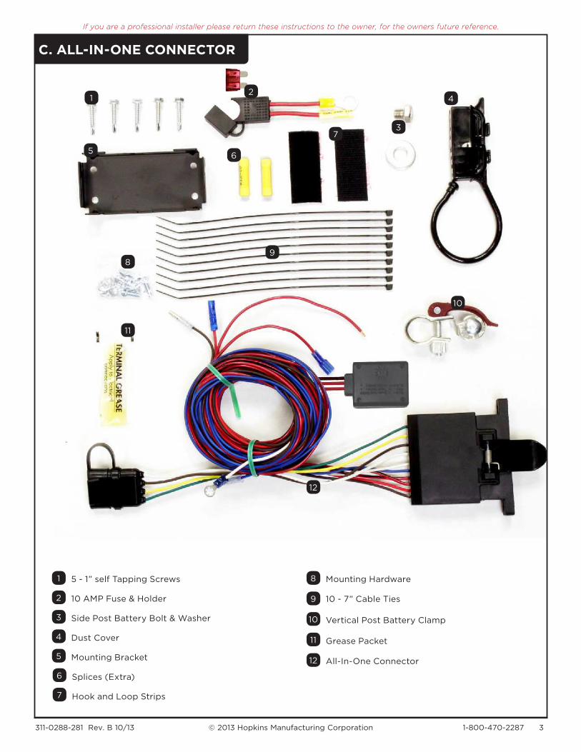
C. ALL-IN-ONE CONNECTOR
7
10
11
12
6
98
7
5 12
5
4 11
4
3 10
3
2 9
2
1 8
1
5 - 1” self Tapping Screws Mounting Hardware
10 AMP Fuse & Holder 10 - 7” Cable Ties
Side Post Battery Bolt & Washer Vertical Post Battery Clamp
Dust Cover Grease Packet
Mounting Bracket All-In-One Connector
Splices (Extra)
Hook and Loop Strips
6

311-0288-281 Rev. B 10/13 © 2013 Hopkins Manufacturing Corporation 1-800-470-2287 4
If you are a professional installer please return these instructions to the owner, for the owners future reference.
D. VACUUM PUMP
E. DUAL CONTROLLER
7
76
6
7
13
13
5
5
5
12
12
4
4
4
11
11
3
3
3
10
10
2
2
2
99
1
1
6 7
5
432
1
1
88
4 - 15” Cable Ties
Dual Controller
1/4” Adapter Valve
Vacuum Pump Harness
1 - Splice Connector
3/8” Check Valve
1/2” x 1/2” x 1/4” Tee
2 - 10/12 Gauge Butt Splices
1/2” Check Valve
1/2” Vacuum Hose
1 - 14/16 Gauge Butt Splice
Vacuum Line (48” Long)
3/8” Vacuum Hose
Mounting Bracket
Hose Clamp
1/4” Rubber Hose
4 - 1/2” Self Tapping Screws
2 - 3/8” Self Tapping Screws
Vacuum Pump
3/8” x 3/8” x 1/4” Tee
6

311-0288-281 Rev. B 10/13 © 2013 Hopkins Manufacturing Corporation 1-800-470-2287 5
If you are a professional installer please return these instructions to the owner, for the owners future reference.
STEP 2: POSITION MAIN UNIT (A)
2-1. Take main unit (A) and position it in the most convenient, out of sight place in the towed vehicle.
(To the right are suggested mounting locations.)
2-2. Route cable (A-1, 2) from main unit as straight as possible to the brake pedal. A 90° bend is allowable with minimum radius of 6 inches.
2-3. It is recommended to hide the cable under thresholds and mats.
DO NOT attach the main unit at this time or cut cable.
UNDER THE SEAT IN THE TRUNK
NOTE
Please check with the vehicle owner to see
where they would like it placed.
WARNING
Main unit is not designed to be installed outside the towed
vehicle or within the engine area.
F. FLEX COIL ADAPTER
3
3
2
2
1
1
Safety Cable
7 Blade Connector
7 Flat Connector
90˚
6˝Radius

311-0288-281 Rev. B 10/13 © 2013 Hopkins Manufacturing Corporation 1-800-470-2287 6
If you are a professional installer please return these instructions to the owner, for the owners future reference.
STEP 3: MOUNTING LOCATION FOR PULLEY AND BRAKE PEDAL CLAMP (B)
3-1. Position brake pedal clamp (B-10) above the brake pedal as shown in (Figure 1). The brake pedal clamp is attached with the supplied bolts, in the pre-drilled holes on the clamp.
3-2. Position pulley (B-5) with large hole downward as shown in (Figure 2).
3-3. Ensure the pulley is directly in-line and as level as possible with the hole in the angle on the brake pedal clamp as shown in (Figure 2).
3-4. Mount pulley to floor of vehicle with the 4, 1.5” self tapping screws (B-4).
WARNING
Make sure the exit side of the screws will not damage
components on the other side of the firewall.
WARNING
Verify the brake pedal clamp does not interfere with any
downward movement of the braking action.
NOTE
Place bolts as close as possible to the brake pedal
arm on each side.
Figure 1
Figure 2
Brake
Pedal
Clamp
Remove
Excess
Large Hole
In Line
Hole in Angle
STEP 4: CUT CABLE TO LENGTH ON MAIN UNIT (A)
4-1. Route the cable to the large hole (Figure 2) in the pulley assembly and place a mark on the black cable cover (A-2). Do not cut yet.
4-2. Measure from end of the steel cable (A-1) to the position marked for cut off on the cable cover. Remember this measurement.
4-3. Find the opening where the steel cable is connected on the bottom of the main unit.
4-4. Grab the steel cable and pull out 1/2 of the length measured in Step 4-2 and add 6” (Figure 3A). Leave the steel cable pulled out.
4-5. Cut at the mark made earlier on the cable cover (Figure 3B).
4-6. Go back to the main unit and carefully push the steel cable back into the cable cover (Figure 3C).
4-7. Bolt main unit to the floor of the towed vehicle with 4, 1” self tapping screws provided with pulley system (B-1).
WARNING
Be careful not to kink the steel cable.
WARNING
The cable cover is a metal sheath wrapped in plastic. Cutting it
improperly could result in failure of the steel cable.
WARNING
In most cases, the cable will have to be cut. If cable is not
correctly cut, the unit will not function properly
Figure 3A
EXAMPLE
If you
measured
20” to cut,
pull out a loop
of 10” and add
6” = 16” total
1/2 of measured
(Step 4-2) + 6”
Figure 3C
Figure 3B

311-0288-281 Rev. B 10/13 © 2013 Hopkins Manufacturing Corporation 1-800-470-2287 7
If you are a professional installer please return these instructions to the owner, for the owners future reference.
5/16”Nuts
5/16” LockWasher
STEP 5: ROUTE AND INSTALL CABLE THROUGH PULLEY SYSTEM (B)
5-1. Slide cable connector (B-2) onto cable. The cable connector will stop on the newly cut end. (Figure 4)
5-2. Heat shrink the tubing (B-3) onto the cable connector and cable cover. The heat shrink will maintain the position on the end of the cable.
5-3. Thread steel cable through pulley and tighten cable assembly onto bracket with 2, 5/16” nuts (B-8) and 2, 5/16” lock washers (B-9) as shown in (Figure 4). Should look like (Figure 5) once completed.
5-4. Pull steel cable through pulley and angle hole. Slip cable clamp (B-7) over steel cable and slide down cable until it is against the angle hole. Pull steel cable tight and tighten cable clamp onto steel cable (Figure 5).
5-5. Cut steel cable 1” from clamp (Figure 5).
5-6. Install heat shrink (B-6) cap on end of the steel cable (Figure 6).
Figure 4 Figure 5 Figure 6
WARNING
Do not pull cable so tight that your brake lights are on or depress the brake pedal.
Large Heat Shrink
Cable Connector
Cut Here 1” from ClampCable Clamp
Angle Hole
SmallHeat Shrink
STEP 6: INSTALL ALL-IN-ONE CONNECTOR ON THE TOWED VEHICLE (C)
6-1. Find a position on the front of the towed vehicle to put the All-in-One Connector (C-12). Use hook and loop strips (C-7) for assistance and install mounting bracket (C-5) with 4 self tapping screws (C-1).
6-2. Apply terminal grease (C-11) to inside of All-in-one connector and attach it to the mounting bracket with mounting hardware (C-8).
6-3. Attach Dust Cover (C-4) to side of mounting bracket. See (Figure 7).
NOTE
This can be mounted in the grille, bottom of the bumper or
wherever convenient to make routing wires easy for your
particular vehicle.
Figure 7
IMPORTANT
When vehicle is not in tow, the dust cover must be
inserted into harness.
Dust Cover

311-0288-281 Rev. B 10/13 © 2013 Hopkins Manufacturing Corporation 1-800-470-2287 8
If you are a professional installer please return these instructions to the owner, for the owners future reference.
STEP 7: RUN WIRES FROM ALL-IN-ONE CONNECTOR TO COMPONENTS
7-1. Route blue, brown and red wires from All-In-One Connector to Main Unit.
7-2. Find an opening or drill a hole to allow wires access into the towed vehicle near the main unit.
7-3. Attach blue, brown and red wires from All-In-One Connector to blue, brown and red wires coming from Main Unit (Figure 8). After connection use cable ties (C-9) to secure wires to vehicle.
7-4. Ground the white wires coming from All-In-One Connector and Main Unit.
7-5. Connect red wire from battery maintainer to fuse and fuse holder (C-2).
7-6. Attach the fuse holder to the battery using the positive (+) terminal. Use the battery post clamp (C-10) for vertical post batteries or battery post bolt and washer (C-3) for side post batteries.
7-7. Please call us at 800-470-2287 to get the correct Towed Vehicle Wiring Kit for your vehicle. If you do not use a Hopkins/BrakeBuddy Towed Vehicle Wiring Kit you will need to cut off the 4-flat coming out the back of the all-in-one connector and hard wire for towed vehicle lighting.
7-8. After the towed vehicle wiring kit is connected ground the white wire coming from the All-In-One Connector.
�o Main Unit
To Main Unit
To Vehicle Frame
To Fuse
To Battery (+)
To Vacuum Pump
To Towed VehicleWiring Kit
To Vehicle Frame
To Pulley andBrake Pedal
Cable
MAIN UNITALLINONE CONNECTOR
BATTERY MAINTAINER
FUSE & HOLDER
VERTICAL POSTBATTERY CLAMP
SIDE POST BATTERY CLAMP
or
Figure 8
IMPORTANT
To preserve battery power, some vehicles require that the fuse holder assembly
be disconnected from the battery when the vehicle is being towed.
WIRING DIAGRAM
WARNING
For vehicles that need the
battery disconnected for
towing behind a motorhome:
All ground wires must be
routed to the vehicle’s battery
to power the Stealth.
If you are a professional installer please return these instructions to the owner, for the owners future reference.
3����������� ���� ���3 © 2013 Hopkins Manufacturing Corporation 1-800-470-2287 9
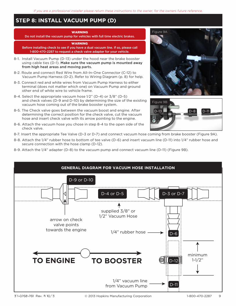
8-1. Install Vacuum Pump (D-13) under the hood near the brake booster using cable ties (D-1). Make sure the vacuum pump is mounted away from high heat areas and moving parts.
8-2. Route and connect Red Wire from All-In-One Connector (C-12) to Vacuum Pump Harness (D-2). Refer to Wiring Diagram (p. 8) for help.
8-3. Connect red and white wires from Vacuum Pump Harness to either terminal (does not matter which one) on Vacuum Pump and ground other end of white wire to vehicle frame.
8-4. Select the appropriate vacuum hose 1 ⁄2” (D-4) or 3/8” (D-5) and check valves (D-9 and D-10) by determining the size of the existing vacuum hose coming out of the brake booster system.
8-5. The Check valve goes between the vacuum boost and engine. After determining the correct position for the check valve, cut the vacuum hose and insert check valve with its arrow pointing to the engine.
8-6. Attach the vacuum hose you chose in step 8-4 to the open side of the check valve.
8-7. Insert the appropriate Tee Valve (D-3 or D-7) and connect vacuum hose coming from brake booster (Figure 9A).
8-8. Attach the 1/4” rubber hose to bottom of tee valve (D-6) and insert vacuum line (D-11) into 1/4” rubber hose and secure connection with the hose clamp (D-12).
8-9. Attach the 1/4” adapter (D-8) to the vacuum pump and connect vacuum line (D-11) (Figure 9B).
STEP 8: INSTALL VACUUM PUMP (D)
arrow on check valve points
towards the engine1/4” rubber hose
supplied 3/8” or 1/2” Vacuum Hose
1/4” vacuum line from Vacuum Pump
TO ENGINE TO BOOSTERminimum
1-1/2”
D-4 or D-5 D-3 or D-7
D-9 or D-10
D-12
D-6
D-11
Figure 9A
Figure 9B
WARNING
Before installing check to see if you have a dual vacuum line. If so, please call
1-800-470-2287 to request a check valve adapter for your vehicle.
WARNING
Do not install the vacuum pump for vehicles with full time electric brakes.
D-8D-13 D-11
GENERAL DIAGRAM FOR VACUUM HOSE INSTALLATION

311-0288-281 Rev. B 10/13 © 2013 Hopkins Manufacturing Corporation 1-800-470-2287 10
If you are a professional installer please return these instructions to the owner, for the owners future reference.
9-1. Take Mounting Bracket (E-5) and secure to the motorhome using 2 - 3/8” Self Tapping Screws (E-7). Ensure there is enough space to access all buttons on Dual Controller and don’t exceed mounting recommendations.
9-2. Attach Dual Controller (E-1) to mounting bracket using the 4 - 1/2” Self Tapping Screws (E-6).
9-3. Adjust Dual Controller to desired angle and tighten screws until snug (Figure 10).
9-4. Splice white wire into existing wire going to negative post on the motorhome battery. Grounding to any other location may cause intermittent controller operation or failure.
9-5. Splice black wire into existing wire going to 20 amp circuit breaker or in-line fuse to the positive terminal on the motorhome’s battery.
9-6. Splice red wire into existing wire going to the cold side of the motorhome’s stop lamp switch located by the brake pedal. Find the
wire by using a circuit tester and probing for the wire that powers the motorhomes stop lamps when the brake pedal is pressed.
9-7. Splice blue wire into existing wire going to 7 blade towing connector at the rear of the motorhome.
WA�� ��Using large or longer screws may damage unit
WA�� ��Wire by function only. Wires may vary by manufacturer
+
–
+
–
DIRECTION OF TRAVEL
+700
-200
CORRECT INCORRECT
Figure 10
mount from –20˚nose
down to +70˚ nose
up and parallel to the
direction of the travel.
Battery (+) - Black
DUAL CONTROLER
TOWINGCONNECTOR
BATTERY
20 amp circuit breakeror in-line fuse
Stoplight Switch = Connect to cold side(Voltage only when pedal is pushed)
Stoplight - Red
Ground (-) - White
Brake - Blue
Chassis Ground
STEP 8: INSTALL VACUUM PUMP (D)
GENERAL WIRING DIAGRAM FOR DUAL CONTROLLERD
IRE
CT
ION
OF
TR
AV
EL

311-0288-281 Rev. B 10/13 © 2013 Hopkins Manufacturing Corporation 1-800-470-2287 11
If you are a professional installer please return these instructions to the owner, for the owners future reference.
Where does main unit mount? Main unit can be mounted at any angle, just not outside of the Towed Vehicle.
Do all vehicles need a vacuum pump? Please consult owner’s manual to see if vacuum brake assist runs while being towed. This information should be under towing requirements. If you have any questions please call 800-470-2287.
How can the Stealth be disabled, in case of an emergency? All you have to do is remove the fuse from the fuse holder by the battery under the hood of your towed vehicle.
What to do if you receive an intermittent “BA” signal? Ensure the 7-way connector on the front of the towed vehicle is securely plugged in and the other end going into the back of the motorhome is lit up red.
Brakes are applied when intentionally disconnecting the towed vehicle from the coach. When the towed vehicle’s connector is intentionally disconnected from the coach, the towed vehicle’s circuit will apply the towed vehicle’s brakes in the same way as it would in an accidental breakaway. Leaving the towed vehicle’s brakes applied when disconnected from the coach will wear the towed vehicle brakes when driven. Therefore, a means has been provided to release the towed vehicle’s brakes under this condition.
How do I release the brake on the towed vehicle? To release the towed vehicle’s brakes when the towed vehicle has been disconnected from the coach, place the dust cap on the towed vehicle’s connector. The towed vehicle’s circuit will detect the dust cap and immediately release the towed vehicle’s brakes.
How do I test the stealth when disconnected from the motorhome?
Before the dust cap has been on the towed vehicle’s connector continuously for three minutes as explained below, the towed vehicle’s circuit may be tested by attaching and removing the dust cap from the towed vehicle’s connector. When the dust cap is removed, the brakes should be observed to be applied. When the dust cap is attached, the brakes should be observed to be released.
After I plug in the dust cap, will the stealth still activate? After the dust cap has been on the towed vehicle’s connector continuously for three minutes, the towed vehicle’s circuit will no longer engage the towed vehicle’s brakes even if the dust cap is removed. When the towed vehicle’s connector is reconnected to the coach, normal operation will resume.
How can you re-enter test mode on the stealth? The testing mode may be re-entered by momentarily disconnecting the power to the towed vehicle’s circuit by remov-ing the power wire, pulling the fuse, etc. When testing is complete the brakes may be released and the testing mode disabled by again attaching the dust cap to the towed vehicle’s connector continuously for three minutes.What happens if I intentionally disconnect the towed vehicle from the coach?
FAQ - FREQUENTLY ASKED QUESTIONS