Embed Size (px)
Citation preview
3A0874EEN
Operation - Maintenance
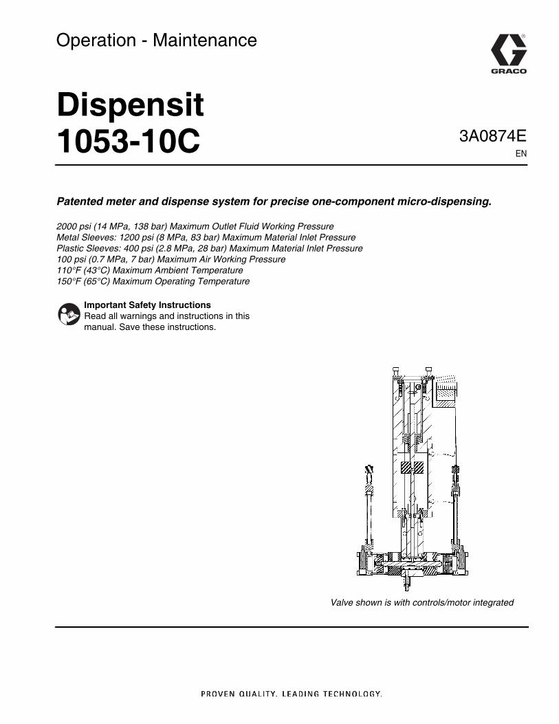
Dispensit1053-10CPatented meter and dispense system for precise one-component micro-dispensing.
2000 psi (14 MPa, 138 bar) Maximum Outlet Fluid Working PressureMetal Sleeves: 1200 psi (8 MPa, 83 bar) Maximum Material Inlet PressurePlastic Sleeves: 400 psi (2.8 MPa, 28 bar) Maximum Material Inlet Pressure100 psi (0.7 MPa, 7 bar) Maximum Air Working Pressure110°F (43°C) Maximum Ambient Temperature150°F (65°C) Maximum Operating Temperature
Important Safety InstructionsRead all warnings and instructions in this manual. Save these instructions.
Valve shown is with controls/motor integrated
2 3A0874E
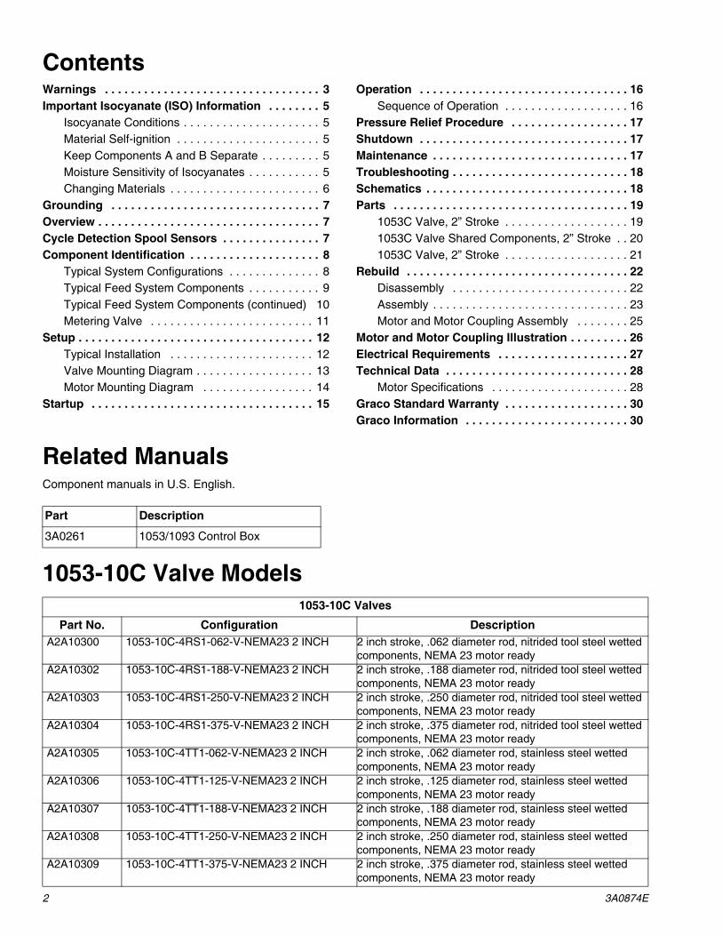
ContentsWarnings . . . . . . . . . . . . . . . . . . . . . . . . . . . . . . . . . 3Important Isocyanate (ISO) Information . . . . . . . . 5
Isocyanate Conditions . . . . . . . . . . . . . . . . . . . . . 5Material Self-ignition . . . . . . . . . . . . . . . . . . . . . . 5Keep Components A and B Separate . . . . . . . . . 5Moisture Sensitivity of Isocyanates . . . . . . . . . . . 5Changing Materials . . . . . . . . . . . . . . . . . . . . . . . 6
Grounding . . . . . . . . . . . . . . . . . . . . . . . . . . . . . . . . 7Overview . . . . . . . . . . . . . . . . . . . . . . . . . . . . . . . . . . 7Cycle Detection Spool Sensors . . . . . . . . . . . . . . . 7Component Identification . . . . . . . . . . . . . . . . . . . . 8
Typical System Configurations . . . . . . . . . . . . . . 8Typical Feed System Components . . . . . . . . . . . 9Typical Feed System Components (continued) 10Metering Valve . . . . . . . . . . . . . . . . . . . . . . . . . 11
Setup . . . . . . . . . . . . . . . . . . . . . . . . . . . . . . . . . . . . 12Typical Installation . . . . . . . . . . . . . . . . . . . . . . 12Valve Mounting Diagram . . . . . . . . . . . . . . . . . . 13Motor Mounting Diagram . . . . . . . . . . . . . . . . . 14
Startup . . . . . . . . . . . . . . . . . . . . . . . . . . . . . . . . . . 15
Operation . . . . . . . . . . . . . . . . . . . . . . . . . . . . . . . . 16Sequence of Operation . . . . . . . . . . . . . . . . . . . 16
Pressure Relief Procedure . . . . . . . . . . . . . . . . . . 17Shutdown . . . . . . . . . . . . . . . . . . . . . . . . . . . . . . . . 17Maintenance . . . . . . . . . . . . . . . . . . . . . . . . . . . . . . 17Troubleshooting . . . . . . . . . . . . . . . . . . . . . . . . . . . 18Schematics . . . . . . . . . . . . . . . . . . . . . . . . . . . . . . . 18Parts . . . . . . . . . . . . . . . . . . . . . . . . . . . . . . . . . . . . 19
1053C Valve, 2” Stroke . . . . . . . . . . . . . . . . . . . 191053C Valve Shared Components, 2” Stroke . . 201053C Valve, 2” Stroke . . . . . . . . . . . . . . . . . . . 21
Rebuild . . . . . . . . . . . . . . . . . . . . . . . . . . . . . . . . . . 22Disassembly . . . . . . . . . . . . . . . . . . . . . . . . . . . 22Assembly . . . . . . . . . . . . . . . . . . . . . . . . . . . . . . 23Motor and Motor Coupling Assembly . . . . . . . . 25
Motor and Motor Coupling Illustration . . . . . . . . . 26Electrical Requirements . . . . . . . . . . . . . . . . . . . . 27Technical Data . . . . . . . . . . . . . . . . . . . . . . . . . . . . 28
Motor Specifications . . . . . . . . . . . . . . . . . . . . . 28Graco Standard Warranty . . . . . . . . . . . . . . . . . . . 30Graco Information . . . . . . . . . . . . . . . . . . . . . . . . . 30
Related ManualsComponent manuals in U.S. English.
1053-10C Valve Models
Part Description
3A0261 1053/1093 Control Box
1053-10C Valves
Part No. Configuration DescriptionA2A10300 1053-10C-4RS1-062-V-NEMA23 2 INCH 2 inch stroke, .062 diameter rod, nitrided tool steel wetted
components, NEMA 23 motor readyA2A10302 1053-10C-4RS1-188-V-NEMA23 2 INCH 2 inch stroke, .188 diameter rod, nitrided tool steel wetted
components, NEMA 23 motor readyA2A10303 1053-10C-4RS1-250-V-NEMA23 2 INCH 2 inch stroke, .250 diameter rod, nitrided tool steel wetted
components, NEMA 23 motor readyA2A10304 1053-10C-4RS1-375-V-NEMA23 2 INCH 2 inch stroke, .375 diameter rod, nitrided tool steel wetted
components, NEMA 23 motor readyA2A10305 1053-10C-4TT1-062-V-NEMA23 2 INCH 2 inch stroke, .062 diameter rod, stainless steel wetted
components, NEMA 23 motor readyA2A10306 1053-10C-4TT1-125-V-NEMA23 2 INCH 2 inch stroke, .125 diameter rod, stainless steel wetted
components, NEMA 23 motor readyA2A10307 1053-10C-4TT1-188-V-NEMA23 2 INCH 2 inch stroke, .188 diameter rod, stainless steel wetted
components, NEMA 23 motor readyA2A10308 1053-10C-4TT1-250-V-NEMA23 2 INCH 2 inch stroke, .250 diameter rod, stainless steel wetted
components, NEMA 23 motor readyA2A10309 1053-10C-4TT1-375-V-NEMA23 2 INCH 2 inch stroke, .375 diameter rod, stainless steel wetted
components, NEMA 23 motor ready
Warnings
3A0874E 3
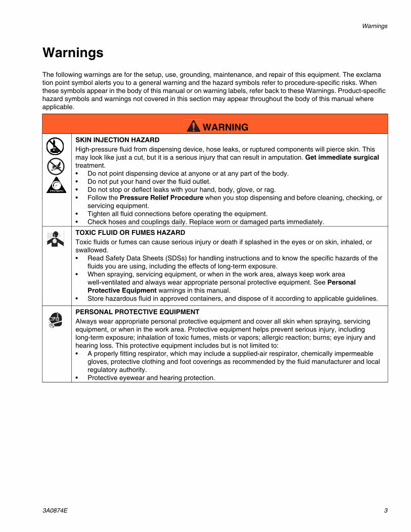
WarningsThe following warnings are for the setup, use, grounding, maintenance, and repair of this equipment. The exclamation point symbol alerts you to a general warning and the hazard symbols refer to procedure-specific risks. When these symbols appear in the body of this manual or on warning labels, refer back to these Warnings. Product-specific hazard symbols and warnings not covered in this section may appear throughout the body of this manual where applicable.
WARNINGSKIN INJECTION HAZARDHigh-pressure fluid from dispensing device, hose leaks, or ruptured components will pierce skin. This may look like just a cut, but it is a serious injury that can result in amputation. Get immediate surgical treatment.• Do not point dispensing device at anyone or at any part of the body.• Do not put your hand over the fluid outlet.• Do not stop or deflect leaks with your hand, body, glove, or rag.• Follow the Pressure Relief Procedure when you stop dispensing and before cleaning, checking, or
servicing equipment.• Tighten all fluid connections before operating the equipment.• Check hoses and couplings daily. Replace worn or damaged parts immediately.
TOXIC FLUID OR FUMES HAZARDToxic fluids or fumes can cause serious injury or death if splashed in the eyes or on skin, inhaled, or swallowed.• Read Safety Data Sheets (SDSs) for handling instructions and to know the specific hazards of the
fluids you are using, including the effects of long-term exposure.• When spraying, servicing equipment, or when in the work area, always keep work area
well-ventilated and always wear appropriate personal protective equipment. See Personal Protective Equipment warnings in this manual.
• Store hazardous fluid in approved containers, and dispose of it according to applicable guidelines.
PERSONAL PROTECTIVE EQUIPMENTAlways wear appropriate personal protective equipment and cover all skin when spraying, servicing equipment, or when in the work area. Protective equipment helps prevent serious injury, including long-term exposure; inhalation of toxic fumes, mists or vapors; allergic reaction; burns; eye injury and hearing loss. This protective equipment includes but is not limited to:• A properly fitting respirator, which may include a supplied-air respirator, chemically impermeable
gloves, protective clothing and foot coverings as recommended by the fluid manufacturer and local regulatory authority.
• Protective eyewear and hearing protection.
Warnings
4 3A0874E
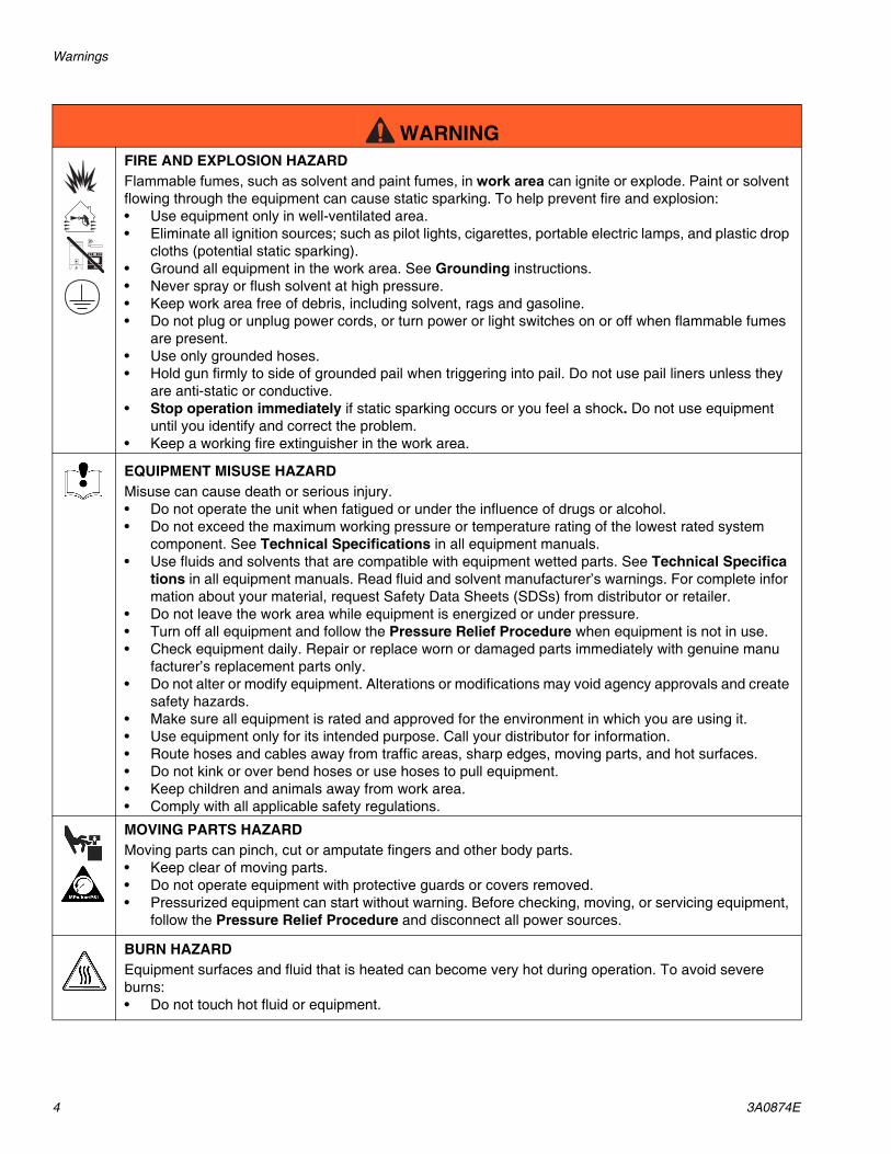
FIRE AND EXPLOSION HAZARDFlammable fumes, such as solvent and paint fumes, in work area can ignite or explode. Paint or solvent flowing through the equipment can cause static sparking. To help prevent fire and explosion:• Use equipment only in well-ventilated area.• Eliminate all ignition sources; such as pilot lights, cigarettes, portable electric lamps, and plastic drop
cloths (potential static sparking).• Ground all equipment in the work area. See Grounding instructions.• Never spray or flush solvent at high pressure.• Keep work area free of debris, including solvent, rags and gasoline.• Do not plug or unplug power cords, or turn power or light switches on or off when flammable fumes
are present.• Use only grounded hoses.• Hold gun firmly to side of grounded pail when triggering into pail. Do not use pail liners unless they
are anti-static or conductive.• Stop operation immediately if static sparking occurs or you feel a shock. Do not use equipment
until you identify and correct the problem.• Keep a working fire extinguisher in the work area.
EQUIPMENT MISUSE HAZARDMisuse can cause death or serious injury.• Do not operate the unit when fatigued or under the influence of drugs or alcohol.• Do not exceed the maximum working pressure or temperature rating of the lowest rated system
component. See Technical Specifications in all equipment manuals.• Use fluids and solvents that are compatible with equipment wetted parts. See Technical Specifica
tions in all equipment manuals. Read fluid and solvent manufacturer’s warnings. For complete information about your material, request Safety Data Sheets (SDSs) from distributor or retailer.
• Do not leave the work area while equipment is energized or under pressure.• Turn off all equipment and follow the Pressure Relief Procedure when equipment is not in use.• Check equipment daily. Repair or replace worn or damaged parts immediately with genuine manu
facturer’s replacement parts only.• Do not alter or modify equipment. Alterations or modifications may void agency approvals and create
safety hazards.• Make sure all equipment is rated and approved for the environment in which you are using it.• Use equipment only for its intended purpose. Call your distributor for information.• Route hoses and cables away from traffic areas, sharp edges, moving parts, and hot surfaces.• Do not kink or over bend hoses or use hoses to pull equipment.• Keep children and animals away from work area.• Comply with all applicable safety regulations.
MOVING PARTS HAZARDMoving parts can pinch, cut or amputate fingers and other body parts.• Keep clear of moving parts.• Do not operate equipment with protective guards or covers removed.• Pressurized equipment can start without warning. Before checking, moving, or servicing equipment,
follow the Pressure Relief Procedure and disconnect all power sources.
BURN HAZARDEquipment surfaces and fluid that is heated can become very hot during operation. To avoid severe burns:• Do not touch hot fluid or equipment.
WARNING
Important Isocyanate (ISO) Information
3A0874E 5
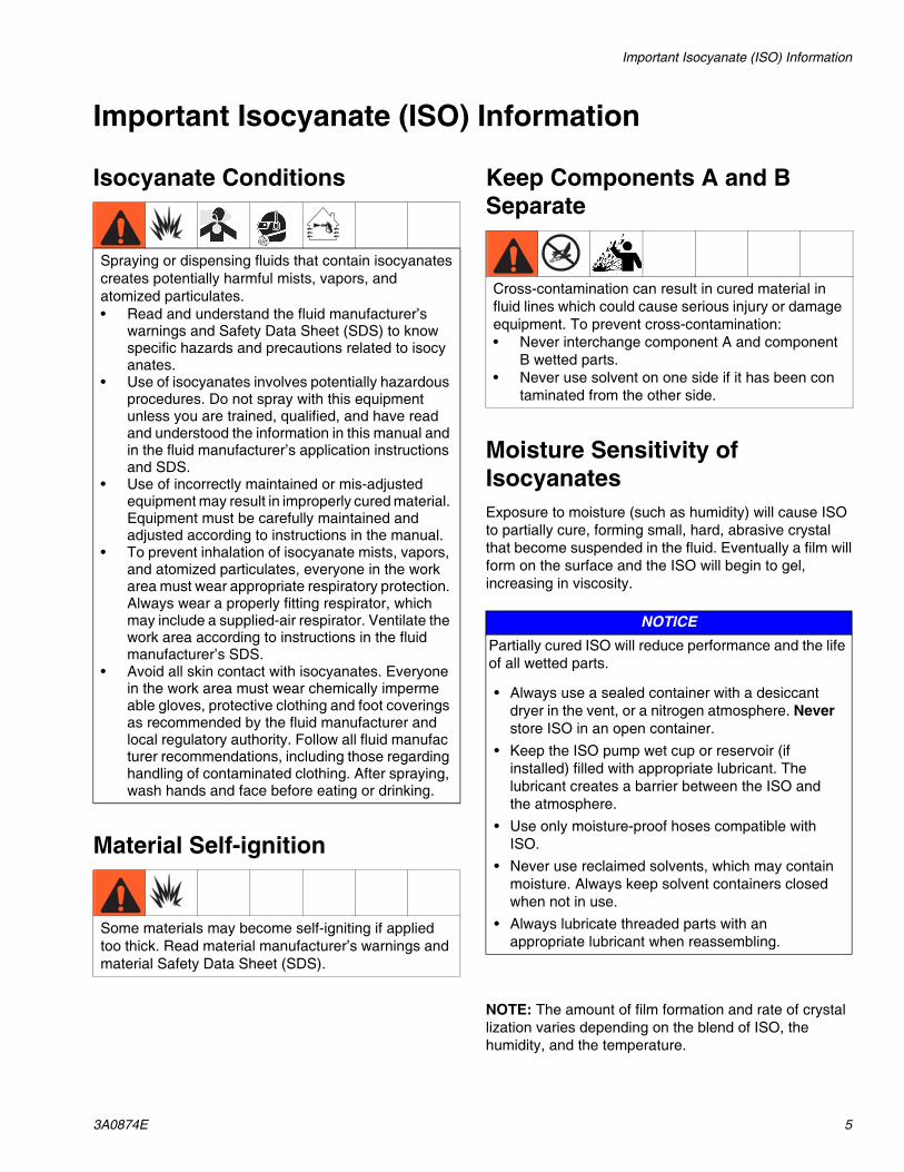
Important Isocyanate (ISO) Information
Isocyanate Conditions
Material Self-ignition
Keep Components A and B Separate
Moisture Sensitivity of IsocyanatesExposure to moisture (such as humidity) will cause ISO to partially cure, forming small, hard, abrasive crystal that become suspended in the fluid. Eventually a film willform on the surface and the ISO will begin to gel, increasing in viscosity.
NOTE: The amount of film formation and rate of crystallization varies depending on the blend of ISO, the humidity, and the temperature.
Spraying or dispensing fluids that contain isocyanatescreates potentially harmful mists, vapors, andatomized particulates.• Read and understand the fluid manufacturer’s
warnings and Safety Data Sheet (SDS) to know specific hazards and precautions related to isocyanates.
• Use of isocyanates involves potentially hazardous procedures. Do not spray with this equipment unless you are trained, qualified, and have read and understood the information in this manual and in the fluid manufacturer’s application instructions and SDS.
• Use of incorrectly maintained or mis-adjusted equipment may result in improperly cured material. Equipment must be carefully maintained and adjusted according to instructions in the manual.
• To prevent inhalation of isocyanate mists, vapors, and atomized particulates, everyone in the work area must wear appropriate respiratory protection. Always wear a properly fitting respirator, which may include a supplied-air respirator. Ventilate the work area according to instructions in the fluid manufacturer’s SDS.
• Avoid all skin contact with isocyanates. Everyone in the work area must wear chemically impermeable gloves, protective clothing and foot coverings as recommended by the fluid manufacturer and local regulatory authority. Follow all fluid manufacturer recommendations, including those regarding handling of contaminated clothing. After spraying, wash hands and face before eating or drinking.
Some materials may become self-igniting if applied too thick. Read material manufacturer’s warnings and material Safety Data Sheet (SDS).
Cross-contamination can result in cured material in fluid lines which could cause serious injury or damage equipment. To prevent cross-contamination:• Never interchange component A and component
B wetted parts.• Never use solvent on one side if it has been con
taminated from the other side.
NOTICEPartially cured ISO will reduce performance and the life of all wetted parts.
• Always use a sealed container with a desiccant dryer in the vent, or a nitrogen atmosphere. Never store ISO in an open container.
• Keep the ISO pump wet cup or reservoir (if installed) filled with appropriate lubricant. The lubricant creates a barrier between the ISO and the atmosphere.
• Use only moisture-proof hoses compatible with ISO.
• Never use reclaimed solvents, which may contain moisture. Always keep solvent containers closed when not in use.
• Always lubricate threaded parts with an appropriate lubricant when reassembling.

Important Isocyanate (ISO) Information
6 3A0874E
Foam Resins with 245 fa Blowing Agents
Some foam blowing agents will froth at temperatures above 90°F (33°C) when not under pressure, especially if agitated. To reduce frothing, minimize preheating in a circulation system.
Changing Materials
NOTICE
Changing the material types used in your equipment requires special attention to avoid equipment damage and downtime.
• When changing materials, flush the equipment multiple times to ensure it is thoroughly clean.
• Always clean the fluid inlet strainers after flushing.• Check with your material manufacturer for
chemical compatibility.• When changing between epoxies and urethanes
or polyureas, disassemble and clean all fluid components and change hoses. Epoxies often have amines on the B (hardener) side. Polyureas often have amines on the B (resin) side.
Grounding
3A0874E 7
Grounding
Metering valve: attach ground wire from grounding lug to true earth ground. See Component Identification starting on page 8.
Fluid hoses: use only electrically conductive hoses.
Feed system components: attach ground wire from grounding lug to true earth ground. See feed system manual for grounding points.
Fluid supply container: follow local code.
Solvent pails used when flushing: follow local code. Use only conductive metal pails, placed on a grounded surface. Do not place the pail on a nonconductive surface, such as paper or cardboard, which interrupts grounding continuity.
OverviewThis single-component meter and dispense device accurately meters liquid and semi-paste materials.
The machine is designed for application that require very small and precisely dispensed beads and/or dots of material at a wide range of material inlet pressures.
The ratio of the flow rate/stroke length to pump shaft area provides the adjustable pressure intensification needed to move the separate liquids through the needle with a flow rate suitable for production requirements.
The complete system is enclosed. See Sequence of Operation on page 16.
Cycle Detection Spool SensorsThe spool sensors are magnetic reed switches and must be connected to an electrical control. An LED on the switch illuminates to indicate the shifting of the spool.
The equipment must be grounded to reduce the risk of static sparking. Static sparking can cause fumes to ignite or explode. Grounding provides an escape wire for the electric current.
Component Identification
8 3A0874E
Component Identification
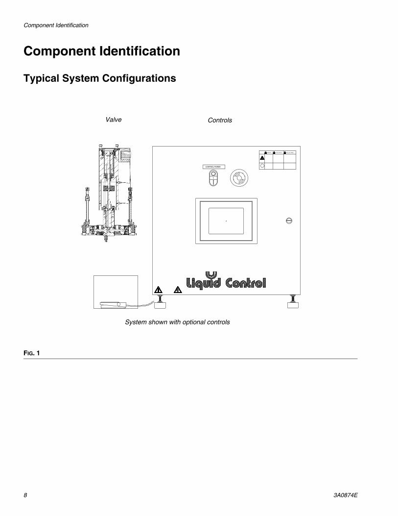
Typical System Configurations
FIG. 1
CONTROL POWER
Valve Controls
System shown with optional controls
Component Identification
3A0874E 9
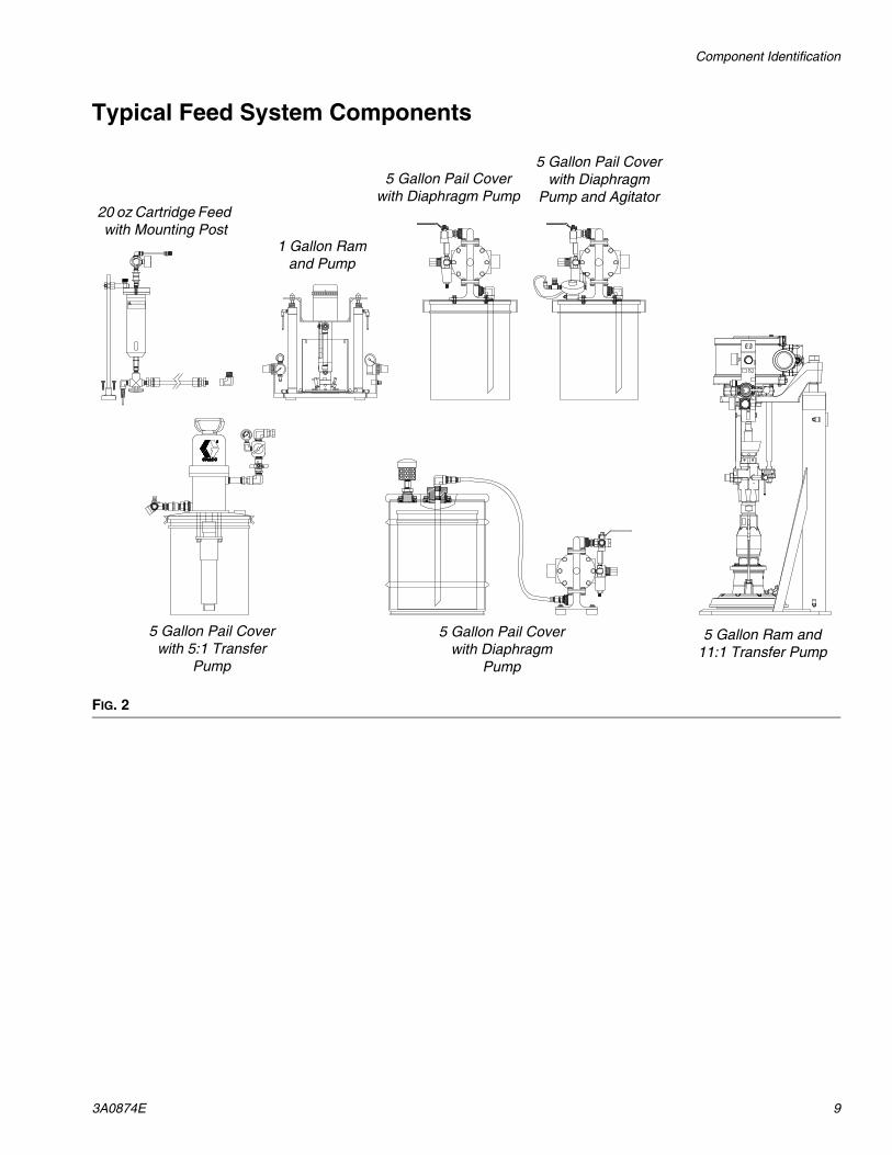
Typical Feed System Components
FIG. 2
DO NOT SERVICE WITHOUTREMOVING AIR PRESSURE ANDWEARING SAFETY GLASSES.
WARNING
F
200
psi0
20 oz Cartridge Feed with Mounting Post
5 Gallon Pail Cover with Diaphragm Pump
1 Gallon Ram and Pump
5 Gallon Pail Cover with Diaphragm
Pump and Agitator
5 Gallon Ram and 11:1 Transfer Pump
5 Gallon Pail Cover with Diaphragm
Pump
5 Gallon Pail Cover with 5:1 Transfer
Pump
Component Identification
10 3A0874E
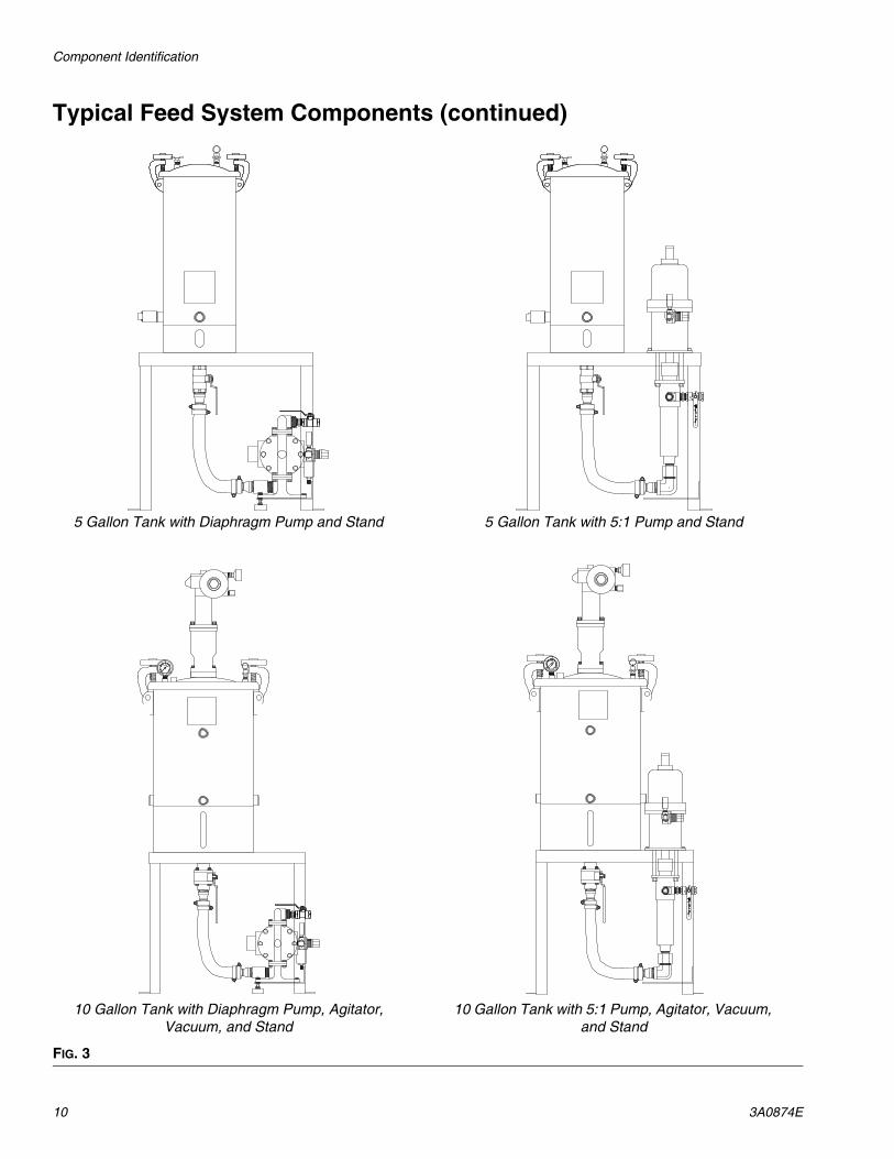
Typical Feed System Components (continued)
FIG. 3
R
0
12
84
psi 30
22
1915
26
R
0
12
84
psi 30
22
1915
26
5 Gallon Tank with Diaphragm Pump and Stand 5 Gallon Tank with 5:1 Pump and Stand
10 Gallon Tank with Diaphragm Pump, Agitator, Vacuum, and Stand
10 Gallon Tank with 5:1 Pump, Agitator, Vacuum, and Stand
Component Identification
3A0874E 11
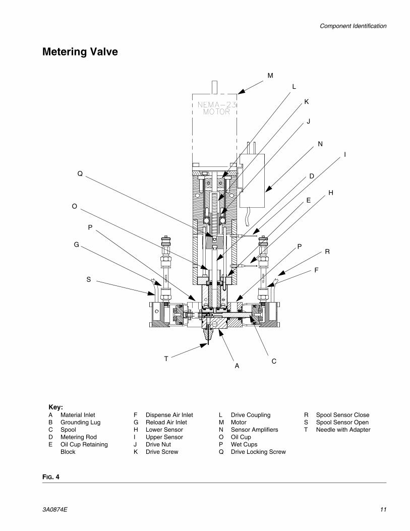
Metering Valve
FIG. 4
GRE
EN
YELLOW
NEMA-23MOTOR
Key:A Material InletB Grounding LugC SpoolD Metering RodE Oil Cup Retaining
Block
F Dispense Air InletG Reload Air InletH Lower SensorI Upper SensorJ Drive NutK Drive Screw
L Drive CouplingM MotorN Sensor AmplifiersO Oil CupP Wet CupsQ Drive Locking Screw
R Spool Sensor CloseS Spool Sensor OpenT Needle with Adapter
S
AC
F
PR
E
D
H
I
N
K
J
L
M
Q
O
G
P
T
Setup
12 3A0874E
Setup
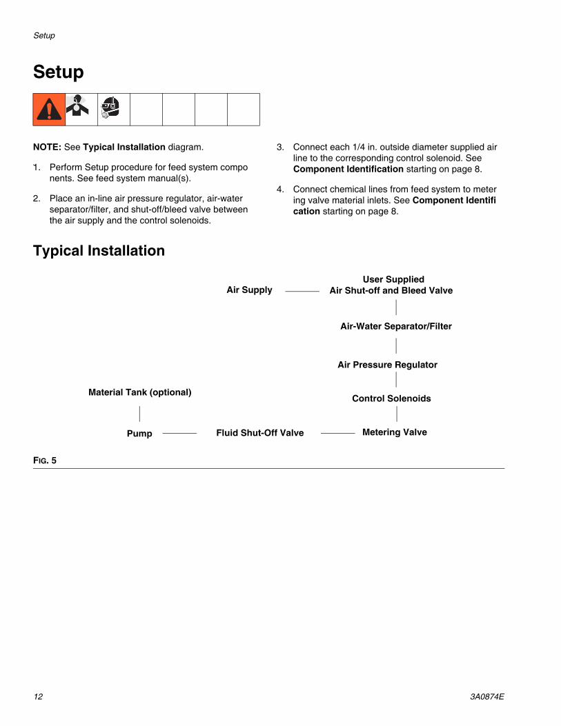
NOTE: See Typical Installation diagram.
2. 1. Perform Setup procedure for feed system components. See feed system manual(s).
2. Place an in-line air pressure regulator, air-water separator/filter, and shut-off/bleed valve between the air supply and the control solenoids.
3. Connect each 1/4 in. outside diameter supplied air line to the corresponding control solenoid. See Component Identification starting on page 8.
4. Connect chemical lines from feed system to metering valve material inlets. See Component Identification starting on page 8.
Typical Installation
FIG. 5
Metering ValvePump
Material Tank (optional)
Fluid Shut-Off Valve
Air Supply Air Shut-off and Bleed Valve
Air Pressure Regulator
User Supplied
Air-Water Separator/Filter
Control Solenoids
Setup
3A0874E 13
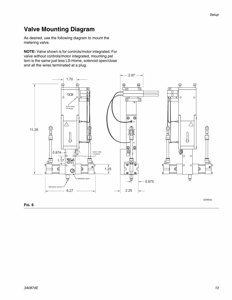
Valve Mounting DiagramAs desired, use the following diagram to mount the metering valve.
NOTE: Valve shown is for controls/motor integrated. For valve without controls/motor integrated, mounting pattern is the same just less LS-Home, solenoid open/close and all the wires terminated at a plug.
FIG. 6
0.874
1.17
1.70
6.27
1.25
11.28
2.87
2.25
0.875
Ø.201 THRU2 PLACES
Ø.201 THRU4 PLACES
MATERIAL OUTLET
MATERIAL INLET
Setup
14 3A0874E
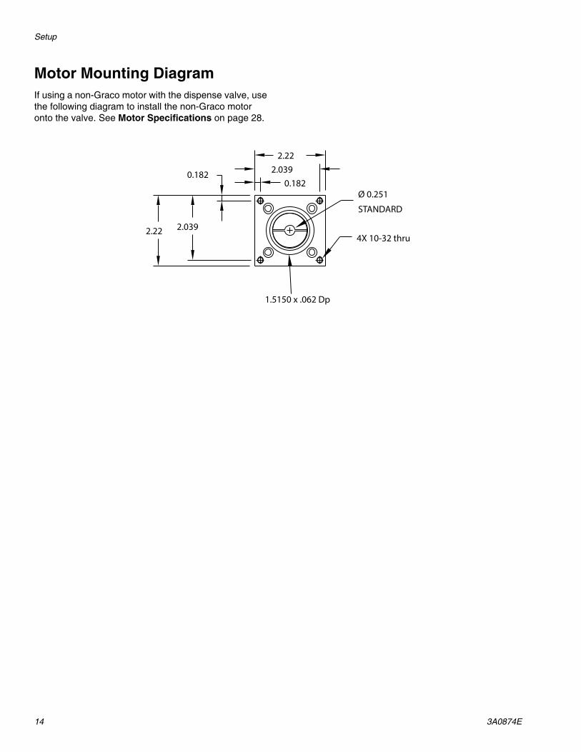
Motor Mounting DiagramIf using a non-Graco motor with the dispense valve, use the following diagram to install the non-Graco motor onto the valve. See Motor Specifications on page 28.
2.22
2.22 2.039
0.182 2.0390.182
Ø 0.251
STANDARD
4X 10-32 thru
1.5150 x .062 Dp
Startup
3A0874E 15
Startup
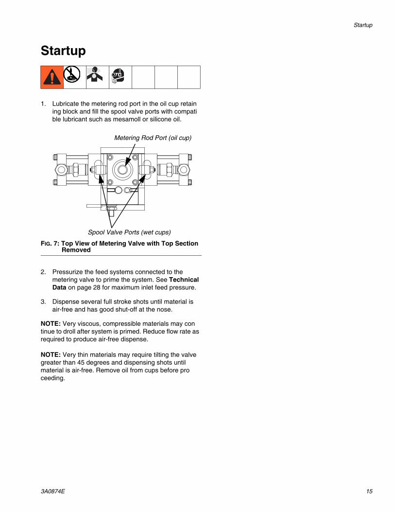
1. Lubricate the metering rod port in the oil cup retaining block and fill the spool valve ports with compatible lubricant such as mesamoll or silicone oil.
2. Pressurize the feed systems connected to the metering valve to prime the system. See Technical Data on page 28 for maximum inlet feed pressure.
3. Dispense several full stroke shots until material is air-free and has good shut-off at the nose.
NOTE: Very viscous, compressible materials may continue to droll after system is primed. Reduce flow rate as required to produce air-free dispense.
NOTE: Very thin materials may require tilting the valve greater than 45 degrees and dispensing shots until material is air-free. Remove oil from cups before proceeding.
FIG. 7: Top View of Metering Valve with Top Section Removed
Metering Rod Port (oil cup)
Spool Valve Ports (wet cups)
Operation
16 3A0874E
OperationThe operation of the 1053 metering valve is controlled by an external source. If a Control Box was purchased, see the Control Box manual for operation instructions. See Related Manuals on page 2.
Sequence of Operation
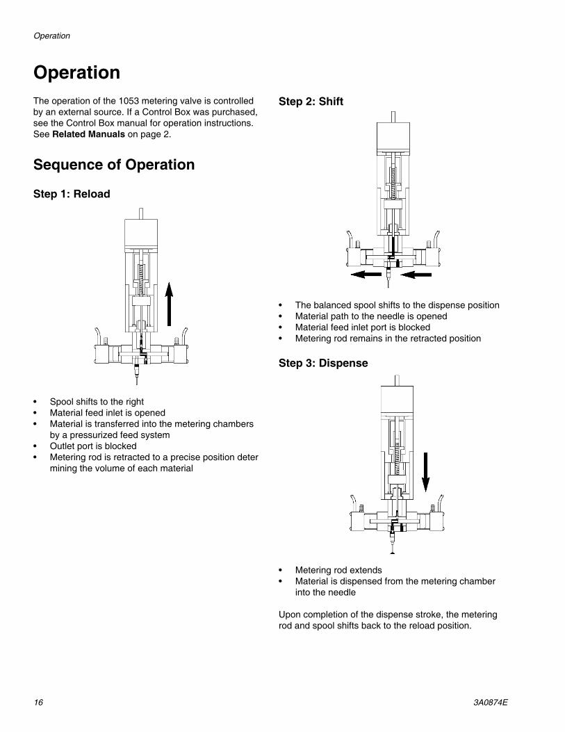
Step 1: Reload
• Spool shifts to the right• Material feed inlet is opened• Material is transferred into the metering chambers
by a pressurized feed system• Outlet port is blocked• Metering rod is retracted to a precise position deter
mining the volume of each material
Step 2: Shift
• The balanced spool shifts to the dispense position• Material path to the needle is opened• Material feed inlet port is blocked• Metering rod remains in the retracted position
Step 3: Dispense
• Metering rod extends• Material is dispensed from the metering chamber
into the needle
Upon completion of the dispense stroke, the metering rod and spool shifts back to the reload position.
Pressure Relief Procedure
3A0874E 17
Pressure Relief Procedure
1. Retract the metering rods. See the Control Box manual. See Related Manuals on page 2.
2. Close the fluid shut-off valve.
3. Remove needle.
4. Dispense 5 shots. Shots should be at least 75% of the full stroke.
5. Extend the metering rod into the tubes. If Graco controls are provided with the system, see the Controls manual. See Related Manuals on page 2.
6. Close the incoming air shut-off/bleed valve that supplies air to the metering valve.
7. Close the incoming air shut-off/bleed valve that supplies the feed system. Refer to feed system manual for pressure relief procedure.
Shutdown
1. Perform Pressure Relief Procedure.
2. Inspect the metering rod for material buildup. Clean as necessary.
3. Lubricate the metering rod with compatible lubricant such as mesamoll or silicone oil.
4. Remove needle adapter and replace with 10-32 set screw.
Maintenance
Perform the following procedures once a shift.
NOTE: If material is leaking, see Troubleshooting on page 18.
Material ReservoirsCheck material levels and refill as necessary. Ensure that the material reservoirs are properly vented.
Air DryerCheck the condition of the desiccant air dryer. Replace as necessary.
Metering Rod Port (oil cup)Lubricate with compatible lubricant such as mesamoll or silicone oil. See FIG. 7 on page 15.
Spool Valve Port (wet cups)Fill with compatible lubricant such as mesamoll or silicone oil. See FIG. 7 on page 15.
Troubleshooting
18 3A0874E
Troubleshooting
SchematicsFor standard machines, the schematics will be included in the Controls Parts manual. See Related Manuals on page 2.
For custom machines, the schematics will be included in the assembly drawings manual.
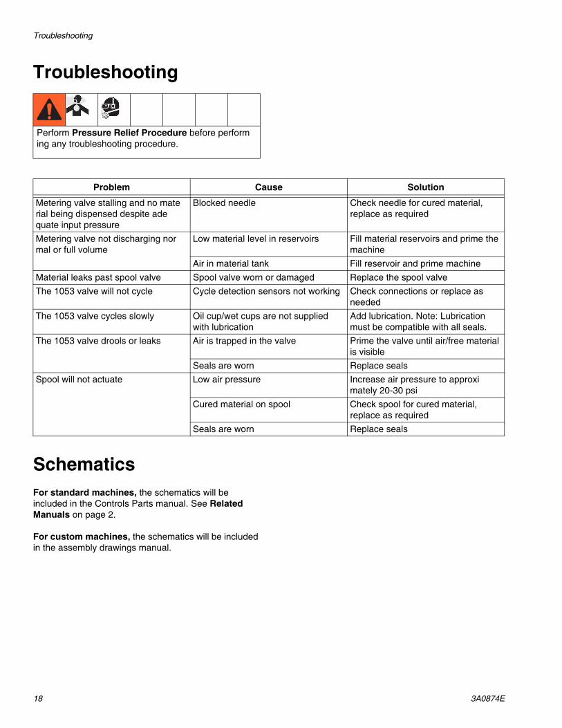
Perform Pressure Relief Procedure before performing any troubleshooting procedure.
Problem Cause Solution
Metering valve stalling and no material being dispensed despite adequate input pressure
Blocked needle Check needle for cured material, replace as required
Metering valve not discharging normal or full volume
Low material level in reservoirs Fill material reservoirs and prime the machine
Air in material tank Fill reservoir and prime machineMaterial leaks past spool valve Spool valve worn or damaged Replace the spool valveThe 1053 valve will not cycle Cycle detection sensors not working Check connections or replace as
neededThe 1053 valve cycles slowly Oil cup/wet cups are not supplied
with lubricationAdd lubrication. Note: Lubrication must be compatible with all seals.
The 1053 valve drools or leaks Air is trapped in the valve Prime the valve until air/free material is visible
Seals are worn Replace sealsSpool will not actuate Low air pressure Increase air pressure to approxi
mately 20-30 psiCured material on spool Check spool for cured material,
replace as requiredSeals are worn Replace seals
Parts
3A0874E 19
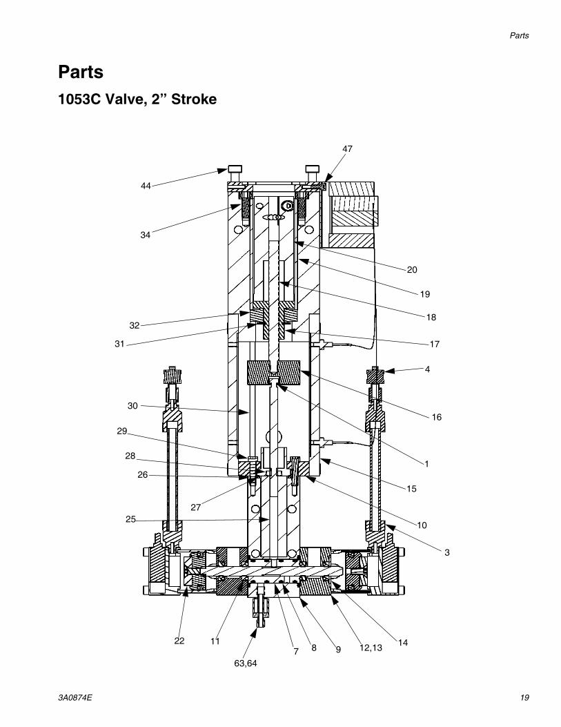
Parts1053C Valve, 2” Stroke
44
34
32
31
30
29
28
26
2725
22 11
63,647 8 9 12,13 14
3
10
15
1
16
4
17
18
19
20
47
Parts
20 3A0874E
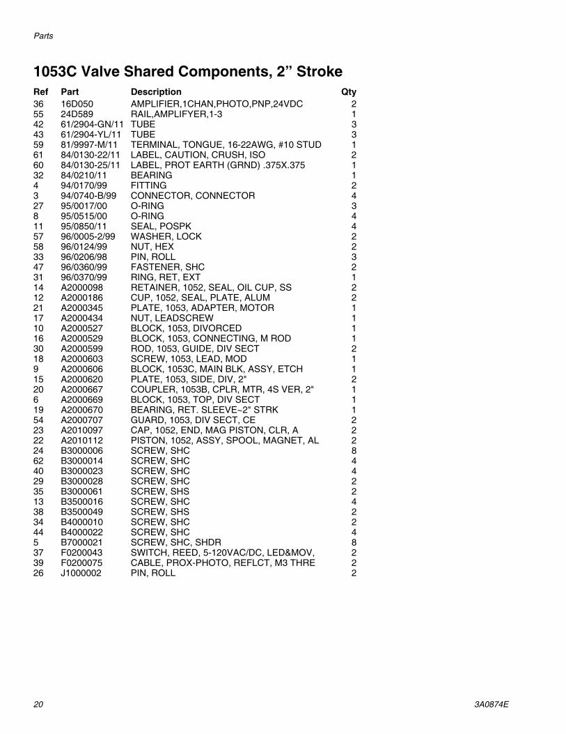
1053C Valve Shared Components, 2” StrokeRef Part Description Qty36 16D050 AMPLIFIER,1CHAN,PHOTO,PNP,24VDC 255 24D589 RAIL,AMPLIFYER,1-3 142 61/2904-GN/11 TUBE 343 61/2904-YL/11 TUBE 359 81/9997-M/11 TERMINAL, TONGUE, 16-22AWG, #10 STUD 161 84/0130-22/11 LABEL, CAUTION, CRUSH, ISO 260 84/0130-25/11 LABEL, PROT EARTH (GRND) .375X.375 132 84/0210/11 BEARING 14 94/0170/99 FITTING 23 94/0740-B/99 CONNECTOR, CONNECTOR 427 95/0017/00 O-RING 38 95/0515/00 O-RING 411 95/0850/11 SEAL, POSPK 457 96/0005-2/99 WASHER, LOCK 258 96/0124/99 NUT, HEX 233 96/0206/98 PIN, ROLL 347 96/0360/99 FASTENER, SHC 231 96/0370/99 RING, RET, EXT 114 A2000098 RETAINER, 1052, SEAL, OIL CUP, SS 212 A2000186 CUP, 1052, SEAL, PLATE, ALUM 221 A2000345 PLATE, 1053, ADAPTER, MOTOR 117 A2000434 NUT, LEADSCREW 110 A2000527 BLOCK, 1053, DIVORCED 116 A2000529 BLOCK, 1053, CONNECTING, M ROD 130 A2000599 ROD, 1053, GUIDE, DIV SECT 218 A2000603 SCREW, 1053, LEAD, MOD 19 A2000606 BLOCK, 1053C, MAIN BLK, ASSY, ETCH 115 A2000620 PLATE, 1053, SIDE, DIV, 2" 220 A2000667 COUPLER, 1053B, CPLR, MTR, 4S VER, 2" 16 A2000669 BLOCK, 1053, TOP, DIV SECT 119 A2000670 BEARING, RET. SLEEVE~2" STRK 154 A2000707 GUARD, 1053, DIV SECT, CE 223 A2010097 CAP, 1052, END, MAG PISTON, CLR, A 222 A2010112 PISTON, 1052, ASSY, SPOOL, MAGNET, AL 224 B3000006 SCREW, SHC 862 B3000014 SCREW, SHC 440 B3000023 SCREW, SHC 429 B3000028 SCREW, SHC 235 B3000061 SCREW, SHS 213 B3500016 SCREW, SHC 438 B3500049 SCREW, SHS 234 B4000010 SCREW, SHC 244 B4000022 SCREW, SHC 45 B7000021 SCREW, SHC, SHDR 837 F0200043 SWITCH, REED, 5-120VAC/DC, LED&MOV, 239 F0200075 CABLE, PROX-PHOTO, REFLCT, M3 THRE 226 J1000002 PIN, ROLL 2
Parts
3A0874E 21
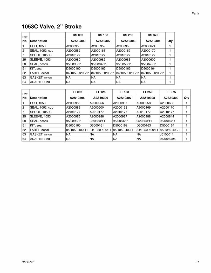
1053C Valve, 2” Stroke
Ref. No. Description
RS 062 RS 188 RS 250 RS 375
QtyA2A10300 A2A10302 A2A10303 A2A10304
1 ROD, 1053 A2000950 A2000952 A2000953 A2000624 12 SEAL, 1052, cup A2000582 A2000168 A2000169 A2000170 17 SPOOL, 1053C A2010127 A2010127 A2010127 A2010127 125 SLEEVE, 1053 A2000980 A2000982 A2000983 A2000600 128 SEAL, pospk 95/0893/11 95/0884/11 95/0850/11 95/0849/11 151 KIT, seal D5000160 D5000162 D5000163 D5000164 152 LABEL, decal 84/1050-1200/11 84/1050-1200/11 84/1050-1200/11 84/1050-1200/11 163 GASKET, nylon NA NA NA NA 164 ADAPTER, ndl NA NA NA NA 1
Ref. No. Description
TT 062 TT 125 TT 188 TT 250 TT 375
QtyA2A10305 A2A10306 A2A10307 A2A10308 A2A10309
1 ROD, 1053 A2000955 A2000956 A2000957 A2000958 A2000635 12 SEAL, 1052, cup A2000582 A2000500 A2000168 A2000169 A2000170 17 SPOOL, 1053C A2010177 A2010177 A2010177 A2010177 A2010177 125 SLEEVE, 1053 A2000985 A2000986 A2000987 A2000988 A2000844 128 SEAL, pospk 95/0893/11 95/0883/11 95/0884/11 95/0850/11 95/0849/11 151 KIT, seal D5000160 D5000161 D5000162 D5000163 D5000164 152 LABEL, decal 84/1050-400/11 84/1050-400/11 84/1050-400/11 84/1050-400/11 84/1050-400/11 163 GASKET, nylon NA NA NA NA J6100011 164 ADAPTER, ndl NA NA NA NA 94/0860/96 1
Rebuild
22 3A0874E
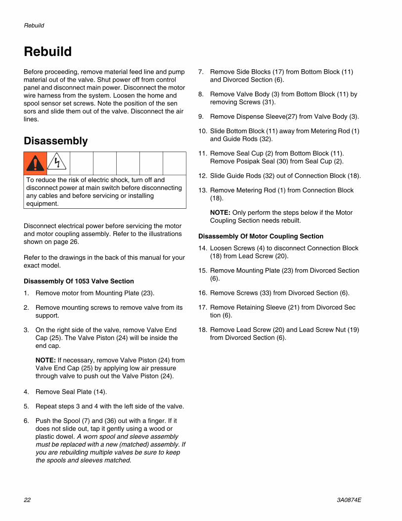
RebuildBefore proceeding, remove material feed line and pump material out of the valve. Shut power off from control panel and disconnect main power. Disconnect the motor wire harness from the system. Loosen the home and spool sensor set screws. Note the position of the sensors and slide them out of the valve. Disconnect the air lines.
Disassembly
Disconnect electrical power before servicing the motor and motor coupling assembly. Refer to the illustrations shown on page 26.
Refer to the drawings in the back of this manual for your exact model.
Disassembly Of 1053 Valve Section
1. Remove motor from Mounting Plate (23).
2. Remove mounting screws to remove valve from its support.
3. On the right side of the valve, remove Valve End Cap (25). The Valve Piston (24) will be inside the end cap.
NOTE: If necessary, remove Valve Piston (24) from Valve End Cap (25) by applying low air pressure through valve to push out the Valve Piston (24).
4. Remove Seal Plate (14).
5. Repeat steps 3 and 4 with the left side of the valve.
6. Push the Spool (7) and (36) out with a finger. If it does not slide out, tap it gently using a wood or plastic dowel. A worn spool and sleeve assembly must be replaced with a new (matched) assembly. If you are rebuilding multiple valves be sure to keep the spools and sleeves matched.
7. Remove Side Blocks (17) from Bottom Block (11) and Divorced Section (6).
8. Remove Valve Body (3) from Bottom Block (11) by removing Screws (31).
9. Remove Dispense Sleeve(27) from Valve Body (3).
10. Slide Bottom Block (11) away from Metering Rod (1) and Guide Rods (32).
11. Remove Seal Cup (2) from Bottom Block (11). Remove Posipak Seal (30) from Seal Cup (2).
12. Slide Guide Rods (32) out of Connection Block (18).
13. Remove Metering Rod (1) from Connection Block (18).
NOTE: Only perform the steps below if the Motor Coupling Section needs rebuilt.
Disassembly Of Motor Coupling Section
14. Loosen Screws (4) to disconnect Connection Block (18) from Lead Screw (20).
15. Remove Mounting Plate (23) from Divorced Section (6).
16. Remove Screws (33) from Divorced Section (6).
17. Remove Retaining Sleeve (21) from Divorced Section (6).
18. Remove Lead Screw (20) and Lead Screw Nut (19) from Divorced Section (6).
To reduce the risk of electric shock, turn off and disconnect power at main switch before disconnecting any cables and before servicing or installing equipment.
Rebuild
3A0874E 23
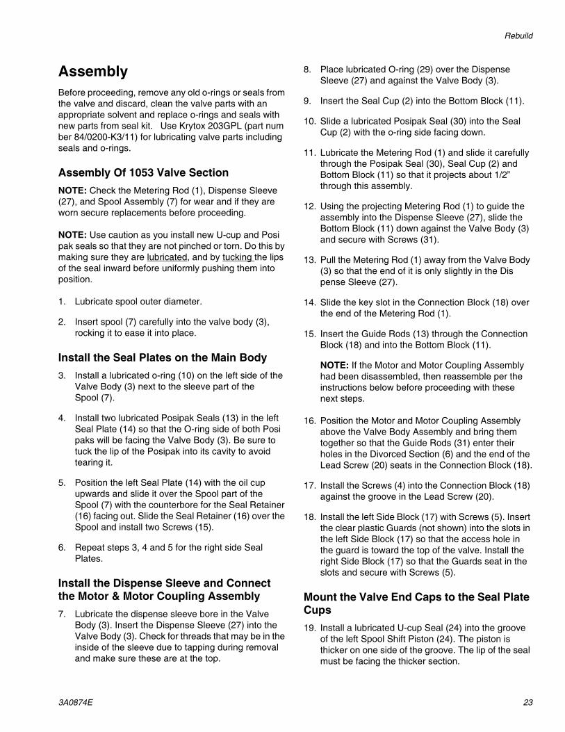
AssemblyBefore proceeding, remove any old o-rings or seals from the valve and discard, clean the valve parts with an appropriate solvent and replace o-rings and seals with new parts from seal kit. Use Krytox 203GPL (part number 84/0200-K3/11) for lubricating valve parts including seals and o-rings.
Assembly Of 1053 Valve SectionNOTE: Check the Metering Rod (1), Dispense Sleeve (27), and Spool Assembly (7) for wear and if they are worn secure replacements before proceeding.
NOTE: Use caution as you install new U-cup and Posipak seals so that they are not pinched or torn. Do this by making sure they are lubricated, and by tucking the lips of the seal inward before uniformly pushing them into position.
1. Lubricate spool outer diameter.
2. Insert spool (7) carefully into the valve body (3), rocking it to ease it into place.
Install the Seal Plates on the Main Body3. Install a lubricated o-ring (10) on the left side of the
Valve Body (3) next to the sleeve part of the Spool (7).
4. Install two lubricated Posipak Seals (13) in the left Seal Plate (14) so that the O-ring side of both Posipaks will be facing the Valve Body (3). Be sure to tuck the lip of the Posipak into its cavity to avoid tearing it.
5. Position the left Seal Plate (14) with the oil cup upwards and slide it over the Spool part of the Spool (7) with the counterbore for the Seal Retainer (16) facing out. Slide the Seal Retainer (16) over the Spool and install two Screws (15).
6. Repeat steps 3, 4 and 5 for the right side Seal Plates.
Install the Dispense Sleeve and Connect the Motor & Motor Coupling Assembly7. Lubricate the dispense sleeve bore in the Valve
Body (3). Insert the Dispense Sleeve (27) into the Valve Body (3). Check for threads that may be in the inside of the sleeve due to tapping during removal and make sure these are at the top.
8. Place lubricated O-ring (29) over the Dispense Sleeve (27) and against the Valve Body (3).
9. Insert the Seal Cup (2) into the Bottom Block (11).
10. Slide a lubricated Posipak Seal (30) into the Seal Cup (2) with the o-ring side facing down.
11. Lubricate the Metering Rod (1) and slide it carefully through the Posipak Seal (30), Seal Cup (2) and Bottom Block (11) so that it projects about 1/2” through this assembly.
12. Using the projecting Metering Rod (1) to guide the assembly into the Dispense Sleeve (27), slide the Bottom Block (11) down against the Valve Body (3) and secure with Screws (31).
13. Pull the Metering Rod (1) away from the Valve Body (3) so that the end of it is only slightly in the Dispense Sleeve (27).
14. Slide the key slot in the Connection Block (18) over the end of the Metering Rod (1).
15. Insert the Guide Rods (13) through the Connection Block (18) and into the Bottom Block (11).
NOTE: If the Motor and Motor Coupling Assembly had been disassembled, then reassemble per the instructions below before proceeding with these next steps.
16. Position the Motor and Motor Coupling Assembly above the Valve Body Assembly and bring them together so that the Guide Rods (31) enter their holes in the Divorced Section (6) and the end of the Lead Screw (20) seats in the Connection Block (18).
17. Install the Screws (4) into the Connection Block (18) against the groove in the Lead Screw (20).
18. Install the left Side Block (17) with Screws (5). Insert the clear plastic Guards (not shown) into the slots in the left Side Block (17) so that the access hole in the guard is toward the top of the valve. Install the right Side Block (17) so that the Guards seat in the slots and secure with Screws (5).
Mount the Valve End Caps to the Seal Plate Cups19. Install a lubricated U-cup Seal (24) into the groove
of the left Spool Shift Piston (24). The piston is thicker on one side of the groove. The lip of the seal must be facing the thicker section.
Rebuild
24 3A0874E
20. Lubricate the bore in the End Cap (25). Slide the Spool Shift Piston (24) into the left End Cap (25) tucking the lip of the U-cup seal (24) into the End Cap (25) carefully.
21. Install the Piston/End Cap onto the left Seal Plate (14) using four Screws (26). Tighten the screws in a cross pattern gradually to prevent binding due to misalignment (like you would tighten lug nuts on a car tire).
22. Push the Spool Rod (7) into the left side until it contacts the piston. Repeat steps 19 - 21 for the right side.
23. Install any removable needles that were previously removed.
24. If your valve has cycle detection, slide the cycle detection sensors into the slots on the end caps and secure with the set screws. Do not overtighten the set screws as the sensors may be damaged.
25. Connect the air lines.
Rebuild
3A0874E 25
Motor and Motor Coupling Assembly1. Assemble Motor Coupler (3) by inserting Roll Pins
(5) and Screws (4).
NOTE: This step is only required if the motor coupler has been disassembled for service or removed from the motor.
2. Assemble Lead Screw Nut (6) with Bearing (9) and E-ring (8).
3. Thread Lead Screw (7) into Lead Screw Nut assembly until lead screw is flush with top of nut.
4. Slide Lead Screw & Nut Assembly into Divorced Section (11).
5. Slide Bearing Retaining Sleeve (2) into Divorced Section (11) taking care to line up the slots in the two pieces. Secure in place with Socket Head Cap Screws (10).
6. Secure Motor Mounting Plate (1) to Divorced Section using Socket Head Cap Screws (15).
7. Place Motor Coupler (3) on motor shaft and lightly snug Screws (4) leaving about ½” of motor shaft visible between Motor Coupler and motor. Insert Motor Coupler (3) through Motor Mounting Plate (1), align 3 Roll Pins (5) and insert into Lead Screw Nut (6) and gently seat the motor.
NOTE: This step is only required if the motor coupler has been disassembled for service or removed from the motor.
8. Remove motor and motor coupler, tighten Screws (4) and reassemble securing motor to Motor Mounting Plate using Socket Head Cap Screws (14).
Motor and Motor Coupling Illustration
26 3A0874E
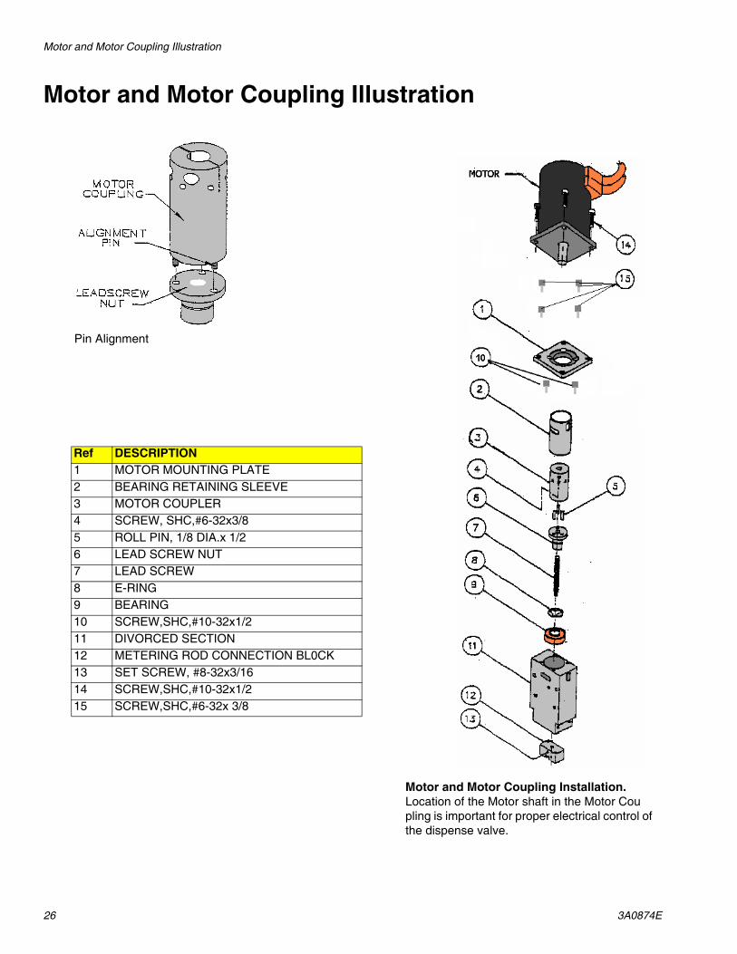
Motor and Motor Coupling Illustration
Pin Alignment
Ref DESCRIPTION1 MOTOR MOUNTING PLATE2 BEARING RETAINING SLEEVE3 MOTOR COUPLER4 SCREW, SHC,#6-32x3/85 ROLL PIN, 1/8 DIA.x 1/2 6 LEAD SCREW NUT7 LEAD SCREW8 E-RING9 BEARING10 SCREW,SHC,#10-32x1/211 DIVORCED SECTION 12 METERING ROD CONNECTION BL0CK13 SET SCREW, #8-32x3/1614 SCREW,SHC,#10-32x1/2 15 SCREW,SHC,#6-32x 3/8
Motor and Motor Coupling Installation. Location of the Motor shaft in the Motor Coupling is important for proper electrical control of the dispense valve.
Electrical Requirements
3A0874E 27
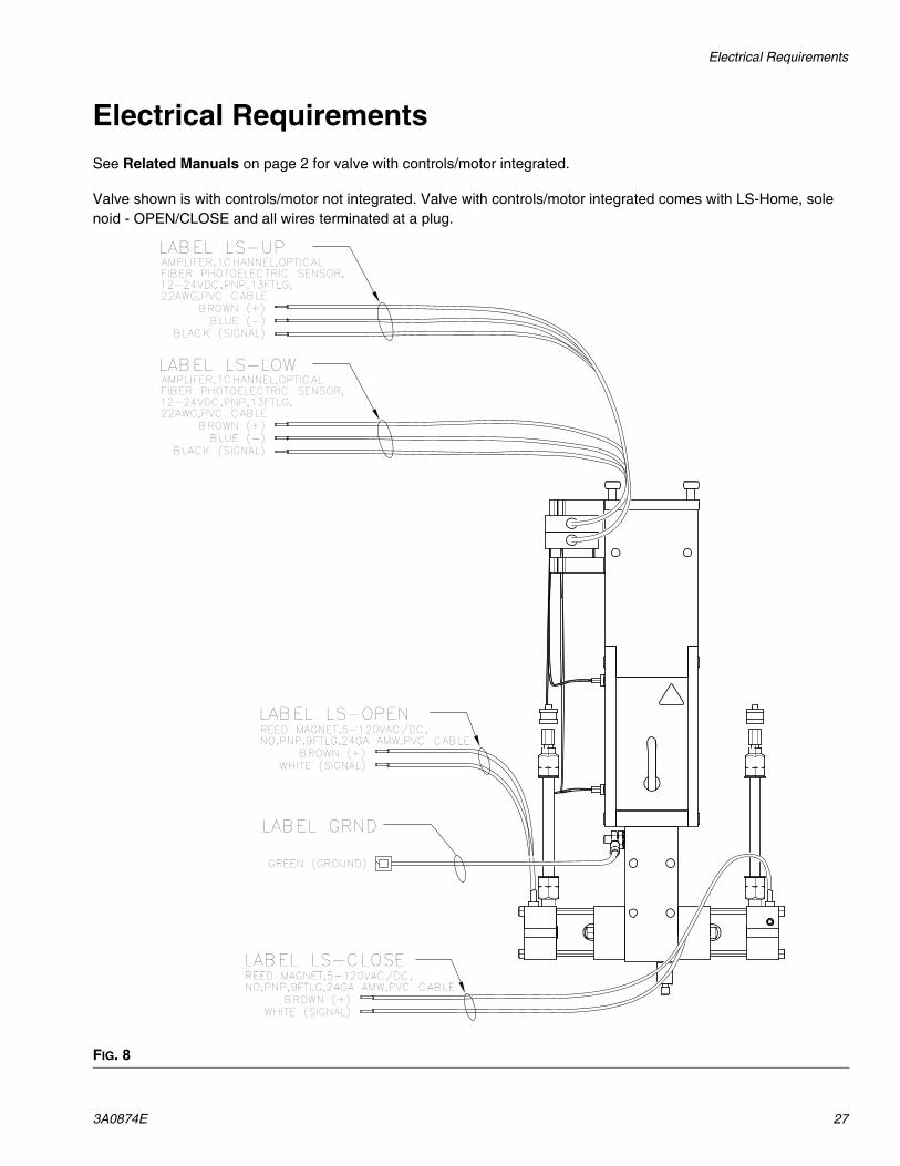
Electrical RequirementsSee Related Manuals on page 2 for valve with controls/motor integrated.
Valve shown is with controls/motor not integrated. Valve with controls/motor integrated comes with LS-Home, solenoid - OPEN/CLOSE and all wires terminated at a plug.
FIG. 8
LABEL LS-LOWAMPLIFER,1CHANNEL,OPTICAL FIBER PHOTOELECTRIC SENSOR,12-24VDC,PNP,13FTLG,22AWG,PVC CABLE
BROWN (+)BLUE (-)
BLACK (SIGNAL)
LABEL LS-CLOSEREED MAGNET,5-120VAC/DC,NO,PNP,9FTLG,24GA AMW,PVC CABLE
BROWN (+)WHITE (SIGNAL)
LABEL LS-OPENREED MAGNET,5-120VAC/DC,NO,PNP,9FTLG,24GA AMW,PVC CABLE
BROWN (+)WHITE (SIGNAL)
LABEL LS-UPAMPLIFER,1CHANNEL,OPTICAL FIBER PHOTOELECTRIC SENSOR,12-24VDC,PNP,13FTLG,22AWG,PVC CABLE
BROWN (+)BLUE (-)
BLACK (SIGNAL)
LABEL GRND
GREEN (GROUND)
Technical Data
28 3A0874E
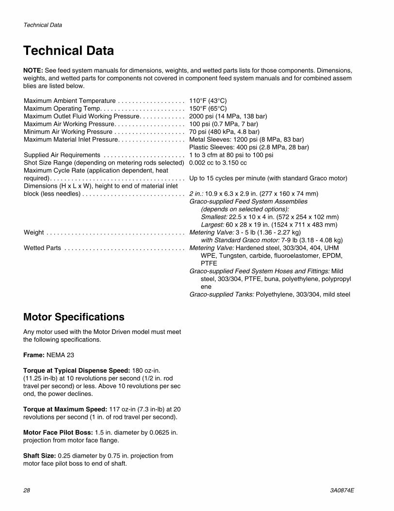
Technical DataNOTE: See feed system manuals for dimensions, weights, and wetted parts lists for those components. Dimensions, weights, and wetted parts for components not covered in component feed system manuals and for combined assemblies are listed below.
Motor SpecificationsAny motor used with the Motor Driven model must meet the following specifications.
Frame: NEMA 23
Torque at Typical Dispense Speed: 180 oz-in. (11.25 in-lb) at 10 revolutions per second (1/2 in. rod travel per second) or less. Above 10 revolutions per second, the power declines.
Torque at Maximum Speed: 117 oz-in (7.3 in-lb) at 20 revolutions per second (1 in. of rod travel per second).
Motor Face Pilot Boss: 1.5 in. diameter by 0.0625 in. projection from motor face flange.
Shaft Size: 0.25 diameter by 0.75 in. projection from motor face pilot boss to end of shaft.
Maximum Ambient Temperature . . . . . . . . . . . . . . . . . . . 110°F (43°C)Maximum Operating Temp. . . . . . . . . . . . . . . . . . . . . . . . 150°F (65°C)Maximum Outlet Fluid Working Pressure. . . . . . . . . . . . . 2000 psi (14 MPa, 138 bar)Maximum Air Working Pressure. . . . . . . . . . . . . . . . . . . . 100 psi (0.7 MPa, 7 bar)Minimum Air Working Pressure . . . . . . . . . . . . . . . . . . . . 70 psi (480 kPa, 4.8 bar)Maximum Material Inlet Pressure. . . . . . . . . . . . . . . . . . . Metal Sleeves: 1200 psi (8 MPa, 83 bar)
Plastic Sleeves: 400 psi (2.8 MPa, 28 bar)Supplied Air Requirements . . . . . . . . . . . . . . . . . . . . . . . 1 to 3 cfm at 80 psi to 100 psiShot Size Range (depending on metering rods selected) 0.002 cc to 3.150 ccMaximum Cycle Rate (application dependent, heat required). . . . . . . . . . . . . . . . . . . . . . . . . . . . . . . . . . . . . . Up to 15 cycles per minute (with standard Graco motor)Dimensions (H x L x W), height to end of material inlet block (less needles) . . . . . . . . . . . . . . . . . . . . . . . . . . . . . 2 in.: 10.9 x 6.3 x 2.9 in. (277 x 160 x 74 mm)
Graco-supplied Feed System Assemblies(depends on selected options):Smallest: 22.5 x 10 x 4 in. (572 x 254 x 102 mm)Largest: 60 x 28 x 19 in. (1524 x 711 x 483 mm)
Weight . . . . . . . . . . . . . . . . . . . . . . . . . . . . . . . . . . . . . . . Metering Valve: 3 - 5 lb (1.36 - 2.27 kg)with Standard Graco motor: 7-9 lb (3.18 - 4.08 kg)
Wetted Parts . . . . . . . . . . . . . . . . . . . . . . . . . . . . . . . . . . Metering Valve: Hardened steel, 303/304, 404, UHMWPE, Tungsten, carbide, fluoroelastomer, EPDM, PTFE
Graco-supplied Feed System Hoses and Fittings: Mild steel, 303/304, PTFE, buna, polyethylene, polypropylene
Graco-supplied Tanks: Polyethylene, 303/304, mild steel

Technical Data
3A0874E 29
All written and visual data contained in this document reflects the latest product information available at the time of publication. Graco reserves the right to make changes at any time without notice.
Original instructions. This manual contains English. MM 3A0874
Graco Headquarters: MinneapolisInternational Offices: Belgium, China, Japan, Korea
GRACO OHIO INC. 8400 PORT JACKSON AVE NW, NORTH CANTON, OH 44720Copyright 2010, Graco Ohio Inc. is registered to ISO 9001
www.graco.comRevision E, April 2017
Graco Standard WarrantyGraco warrants all equipment referenced in this document which is manufactured by Graco and bearing its name to be free from defects in material and workmanship on the date of sale to the original purchaser for use. With the exception of any special, extended, or limited warranty published by Graco, Graco will, for a period of twelve months from the date of sale, repair or replace any part of the equipment determined by Graco to be defective. This warranty applies only when the equipment is installed, operated and maintained in accordance with Graco’s written recommendations.
This warranty does not cover, and Graco shall not be liable for general wear and tear, or any malfunction, damage or wear caused by faulty installation, misapplication, abrasion, corrosion, inadequate or improper maintenance, negligence, accident, tampering, or substitution of non-Graco component parts. Nor shall Graco be liable for malfunction, damage or wear caused by the incompatibility of Graco equipment with structures, accessories, equipment or materials not supplied by Graco, or the improper design, manufacture, installation, operation or maintenance of structures, accessories, equipment or materials not supplied by Graco.
This warranty is conditioned upon the prepaid return of the equipment claimed to be defective to an authorized Graco distributor for verification of the claimed defect. If the claimed defect is verified, Graco will repair or replace free of charge any defective parts. The equipment will be returned to the original purchaser transportation prepaid. If inspection of the equipment does not disclose any defect in material or workmanship, repairs will be made at a reasonable charge, which charges may include the costs of parts, labor, and transportation.
THIS WARRANTY IS EXCLUSIVE, AND IS IN LIEU OF ANY OTHER WARRANTIES, EXPRESS OR IMPLIED, INCLUDING BUT NOT LIMITED TO WARRANTY OF MERCHANTABILITY OR WARRANTY OF FITNESS FOR A PARTICULAR PURPOSE.
Graco’s sole obligation and buyer’s sole remedy for any breach of warranty shall be as set forth above. The buyer agrees that no other remedy (including, but not limited to, incidental or consequential damages for lost profits, lost sales, injury to person or property, or any other incidental or consequential loss) shall be available. Any action for breach of warranty must be brought within two (2) years of the date of sale.
GRACO MAKES NO WARRANTY, AND DISCLAIMS ALL IMPLIED WARRANTIES OF MERCHANTABILITY AND FITNESS FOR A PARTICULAR PURPOSE, IN CONNECTION WITH ACCESSORIES, EQUIPMENT, MATERIALS OR COMPONENTS SOLD BUT NOT MANUFACTURED BY GRACO. These items sold, but not manufactured by Graco (such as electric motors, switches, hose, etc.), are subject to the warranty, if any, of their manufacturer. Graco will provide purchaser with reasonable assistance in making any claim for breach of these warranties.
In no event will Graco be liable for indirect, incidental, special or consequential damages resulting from Graco supplying equipment hereunder, or the furnishing, performance, or use of any products or other goods sold hereto, whether due to a breach of contract, breach of warranty, the negligence of Graco, or otherwise.
FOR GRACO CANADA CUSTOMERSThe Parties acknowledge that they have required that the present document, as well as all documents, notices and legal proceedings entered into, given or instituted pursuant hereto or relating directly or indirectly hereto, be drawn up in English. Les parties reconnaissent avoir convenu que la rédaction du présente document sera en Anglais, ainsi que tous documents, avis et procédures judiciaires exécutés, donnés ou intentés, à la suite de ou en rapport, directement ou indirectement, avec les procédures concernées.
Graco InformationSealant and Adhesive Dispensing Equipment
For the latest information about Graco products, visit www.graco.com.For patent information, see www.graco.com/patents.
TO PLACE AN ORDER, contact your Graco distributor, go to www.graco.com and select “Where to Buy” in the top blue bar, or call to find the nearest distributor.
If calling from the US: 800-746-1334If calling from outside the US: 0-1-330-966-3000