Embed Size (px)
Citation preview
ELMAG Corp. ElectroMagnetic Consulting Services
136 Chalkboard Ct Moorestown, New Jersey, USA 08057(856)234-2165 (201)919-6437 E-mail < [email protected]>
Infolytica Engage User Conference 2015
3D Analysis of induction melting furnaces with cold crucible
1
Vitaly Peysakhovich, Ph.D
2015

• The reduction of contamination is happening because the contact of the molten load with the ceramics is replacedby its contact with the water cooled copper.
• The development of some new technical trends requires super pure materials that can not be melted in the regularcold crucible furnaces because they are contaminated even by contact with copper.
• So, the melting of the materials can be achieved only by eliminating any contacts of the molten load with thecrucible surface. It can be done by using the coil magnetic field to press out the molten metal from the crucible.
• The design of these types of furnaces requires the development of special calculation methods. This methods haveto take into consideration the combination of strongly tangled electromagnetic, thermal, hydrostatic and electro-dynamic processes.
• The objective of this presentation is to show such method.
The induction furnaces with the cold crucible (CCIF) are broadly used for the melting of pure metals and alloys.The furnaces strongly reduce load contamination against traditional furnaces with the ceramic crucible.
Fig. 1 3D models of furnaces with the cold cruciblea)solid load,12- sections crucible, 1/4 of furnace volume; b) partially molten load, 24- sections crucible, 1/8 of furnace volume;1-solid load, 2-molten load, 3-crucible bottom plate, 4-crucible sections, 5-gaps between sections, 6-flux ring, 7-induction coil .
Infolytica Engage User Conference 2015
3D Analysis of induction melting furnaces with cold crucible
2
Infolytica Engage User Conference 2015 3
3D Analysis of induction melting furnaces with cold crucible
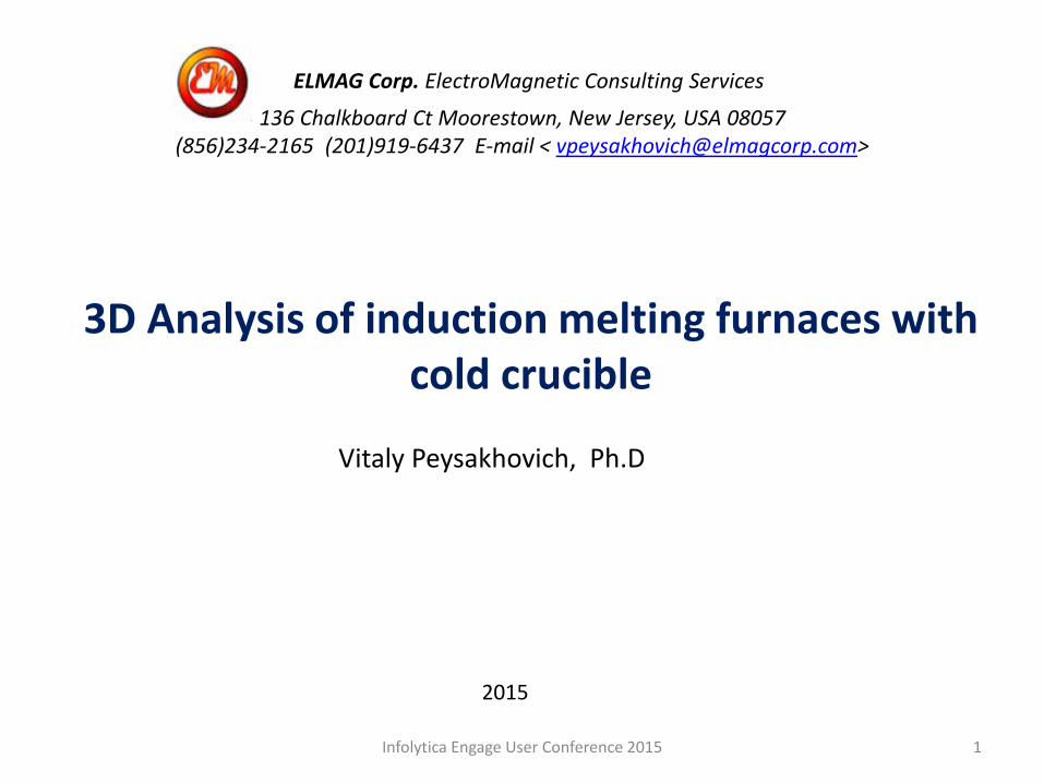
A workflow of the developed method
• The total time for the melt, starting from the turn on ofthe furnace to the actual metal casting, has to bedivided into a number of time steps.
• The time step#1 is the time between the start of theheating process and the actual melting of the topsurface of the load. It differs from other time stepsbecause it requires a separate solid load calculationmethod.
• The time of the next time steps is calculated by dividingthe remaining time by the number of the time stepsw/o time step#1.
• The calculations in each of the time steps is done by ablock made of a MagNet model and a postprocessor,based on the math software "Mathcad"(MCD);
• The MagNet models make electromagnetic (EM)calculations and transfer the results to MCD program.The MCD program is then uses the results for thermal ,hydrostatic and electrodynamic calculations.
• The final results of each time step are: integralparameters and the shape of the partially molten load.The results are transferred to the next time block andto the calc output.
• The calculation of the shape of the load meniscusrequires iteration approach, so the meniscus data ispassing , as feedback, in its own MagNet model.
Fig. 2 Calculation workflow.
Infolytica Engage User Conference 2015 4
3D Analysis of induction melting furnaces with cold crucible
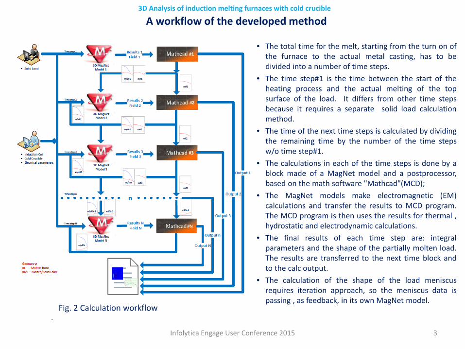
Fig.3.Distribution of magnetic field in the system coil-crucible-load
1- cold crucible profile
Magnetic flux created by induction coil can beconditionally divided into three parts: • coil flux leakage • flux along the crucible` s sections• flux after crucible sections.
Calculation of electromagnetic processes in CCIFThe EM calculation provides the following results:◦ Current density, power and magnetic field distribution
in the load, cold crucible, field ring and induction coil;◦ Electrical losses in the cold crucible, induction coil and field ring;◦ Furnace electrical parameters (current, voltage and total energy);◦ Magnetic flux passage between the induction coil and the load.
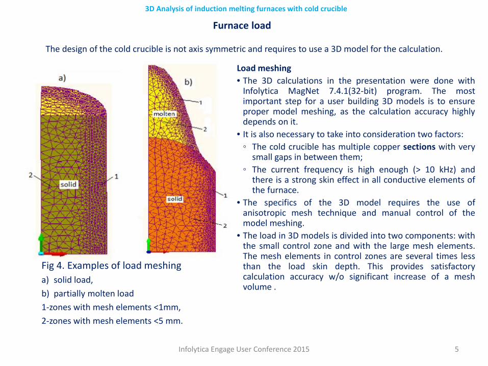
Furnace load
Load meshing• The 3D calculations in the presentation were done with
Infolytica MagNet 7.4.1(32-bit) program. The mostimportant step for a user building 3D models is to ensureproper model meshing, as the calculation accuracy highlydepends on it.
• It is also necessary to take into consideration two factors:◦ The cold crucible has multiple copper sections with very
small gaps in between them;◦ The current frequency is high enough (> 10 kHz) and
there is a strong skin effect in all conductive elements ofthe furnace.
• The specifics of the 3D model requires the use ofanisotropic mesh technique and manual control of themodel meshing.
• The load in 3D models is divided into two components: withthe small control zone and with the large mesh elements.The mesh elements in control zones are several times lessthan the load skin depth. This provides satisfactorycalculation accuracy w/o significant increase of a meshvolume .
Infolytica Engage User Conference 2015 5
3D Analysis of induction melting furnaces with cold crucible
The design of the cold crucible is not axis symmetric and requires to use a 3D model for the calculation.
Fig 4. Examples of load meshinga) solid load, b) partially molten load1-zones with mesh elements <1mm, 2-zones with mesh elements <5 mm.
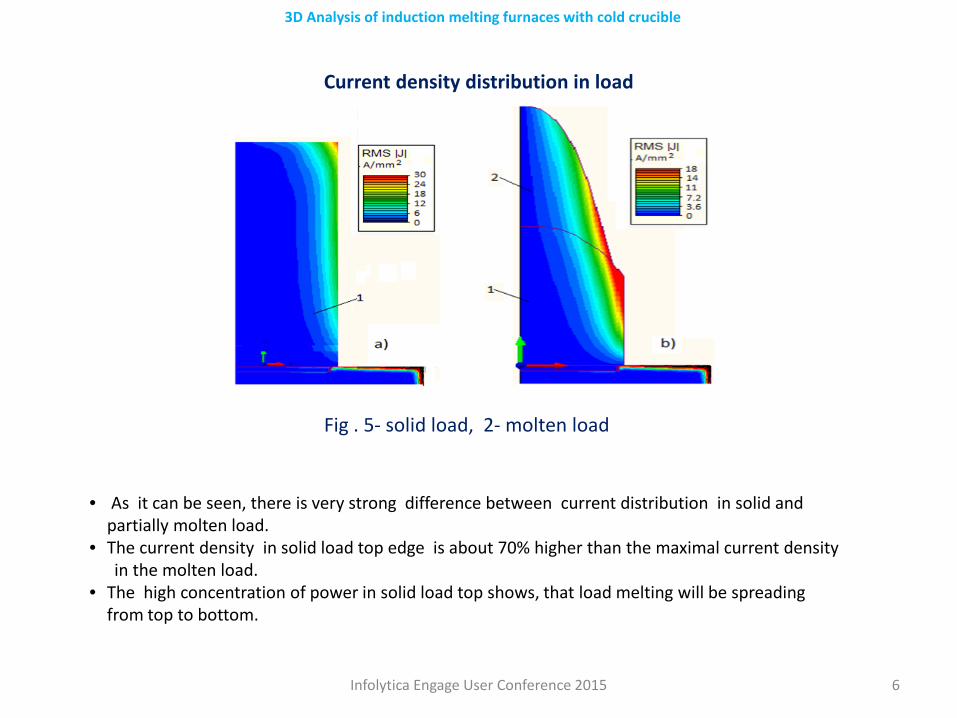
Current density distribution in load
Infolytica Engage User Conference 2015 6
3D Analysis of induction melting furnaces with cold crucible
Fig . 5- solid load, 2- molten load
• As it can be seen, there is very strong difference between current distribution in solid and partially molten load.
• The current density in solid load top edge is about 70% higher than the maximal current densityin the molten load.
• The high concentration of power in solid load top shows, that load melting will be spreading from top to bottom.
Infolytica Engage User Conference 2015 7
3D Analysis of induction melting furnaces with cold crucible
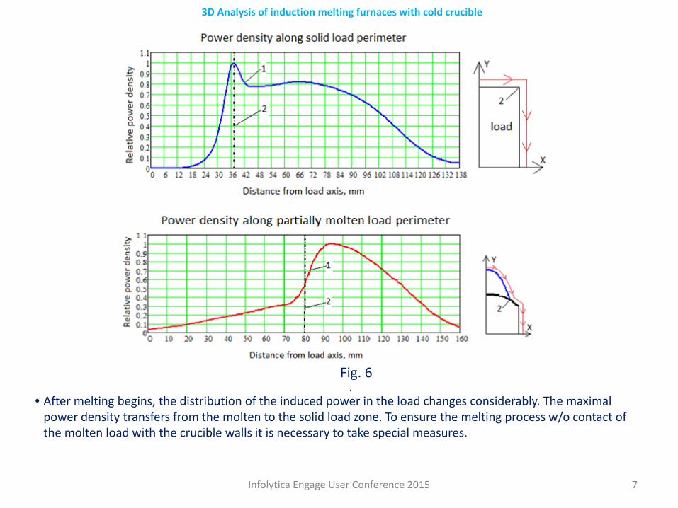
• After melting begins, the distribution of the induced power in the load changes considerably. The maximal power density transfers from the molten to the solid load zone. To ensure the melting process w/o contact of the molten load with the crucible walls it is necessary to take special measures.
Fig. 6.
Infolytica Engage User Conference 2015 8
3D Analysis of induction melting furnaces with cold crucible
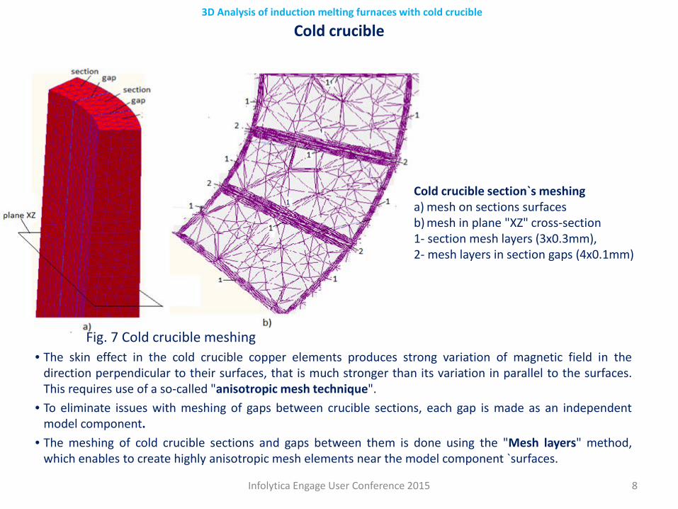
• The skin effect in the cold crucible copper elements produces strong variation of magnetic field in thedirection perpendicular to their surfaces, that is much stronger than its variation in parallel to the surfaces.This requires use of a so-called "anisotropic mesh technique".
• To eliminate issues with meshing of gaps between crucible sections, each gap is made as an independentmodel component.
• The meshing of cold crucible sections and gaps between them is done using the "Mesh layers" method,which enables to create highly anisotropic mesh elements near the model component `surfaces.
Cold crucible section`s meshinga) mesh on sections surfacesb) mesh in plane "XZ" cross-section1- section mesh layers (3x0.3mm), 2- mesh layers in section gaps (4x0.1mm)
Cold crucible
Fig. 7 Cold crucible meshing.
Infolytica Engage User Conference 2015 9
3D Analysis of induction melting furnaces with cold crucible
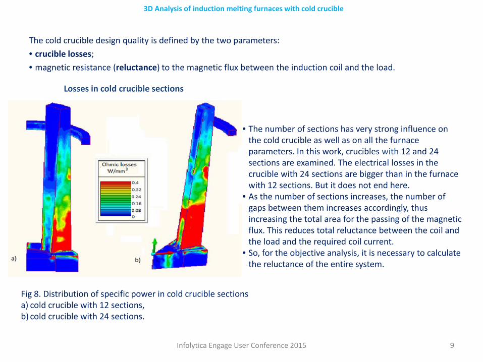
The cold crucible design quality is defined by the two parameters:• crucible losses;• magnetic resistance (reluctance) to the magnetic flux between the induction coil and the load.
• The number of sections has very strong influence on the cold crucible as well as on all the furnace parameters. In this work, crucibles with 12 and 24 sections are examined. The electrical losses in the crucible with 24 sections are bigger than in the furnace with 12 sections. But it does not end here.
• As the number of sections increases, the number of gaps between them increases accordingly, thus increasing the total area for the passing of the magnetic flux. This reduces total reluctance between the coil and the load and the required coil current.
• So, for the objective analysis, it is necessary to calculate the reluctance of the entire system.
Fig 8. Distribution of specific power in cold crucible sectionsa) cold crucible with 12 sections, b) cold crucible with 24 sections.
Losses in cold crucible sections
Infolytica Engage User Conference 2015 10
3D Analysis of induction melting furnaces with cold crucible
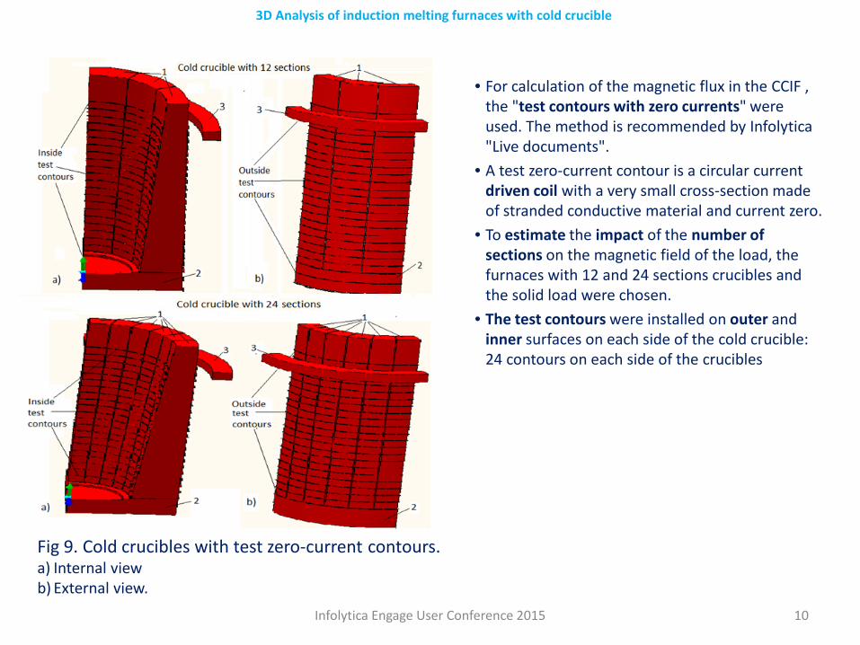
• For calculation of the magnetic flux in the CCIF , the "test contours with zero currents" were used. The method is recommended by Infolytica"Live documents".
• A test zero-current contour is a circular current driven coil with a very small cross-section made of stranded conductive material and current zero.
• To estimate the impact of the number of sections on the magnetic field of the load, the furnaces with 12 and 24 sections crucibles and the solid load were chosen.
• The test contours were installed on outer and inner surfaces on each side of the cold crucible: 24 contours on each side of the crucibles
Fig 9. Cold crucibles with test zero-current contours.a) Internal view b) External view.
Infolytica Engage User Conference 2015 11
3D Analysis of induction melting furnaces with cold crucible
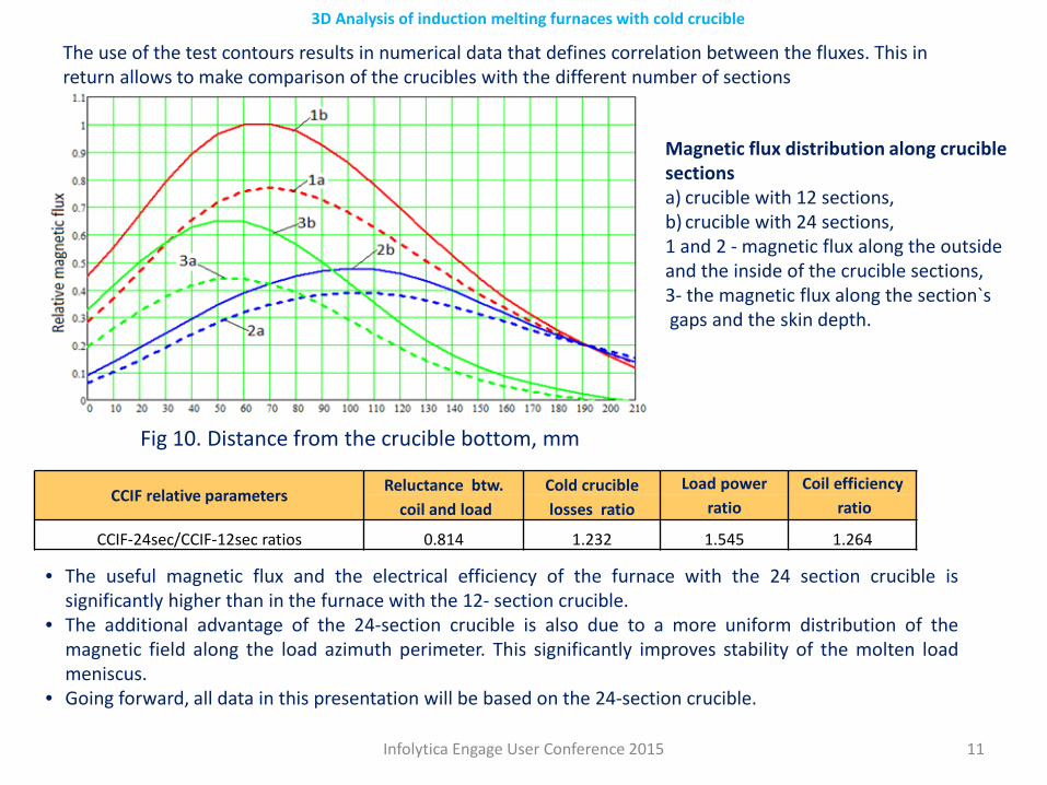
The use of the test contours results in numerical data that defines correlation between the fluxes. This in return allows to make comparison of the crucibles with the different number of sections
Magnetic flux distribution along crucible sectionsa) crucible with 12 sections, b) crucible with 24 sections,1 and 2 - magnetic flux along the outside and the inside of the crucible sections,3- the magnetic flux along the section`sgaps and the skin depth.
Fig 10. Distance from the crucible bottom, mm
CCIF relative parameters Reluctance btw. Cold crucible Load power Coil efficiencycoil and load losses ratio ratio ratio
CCIF-24sec/CCIF-12sec ratios 0.814 1.232 1.545 1.264
• The useful magnetic flux and the electrical efficiency of the furnace with the 24 section crucible issignificantly higher than in the furnace with the 12- section crucible.
• The additional advantage of the 24-section crucible is also due to a more uniform distribution of themagnetic field along the load azimuth perimeter. This significantly improves stability of the molten loadmeniscus.
• Going forward, all data in this presentation will be based on the 24-section crucible.
Infolytica Engage User Conference 2015 12
3D Analysis of induction melting furnaces with cold crucible
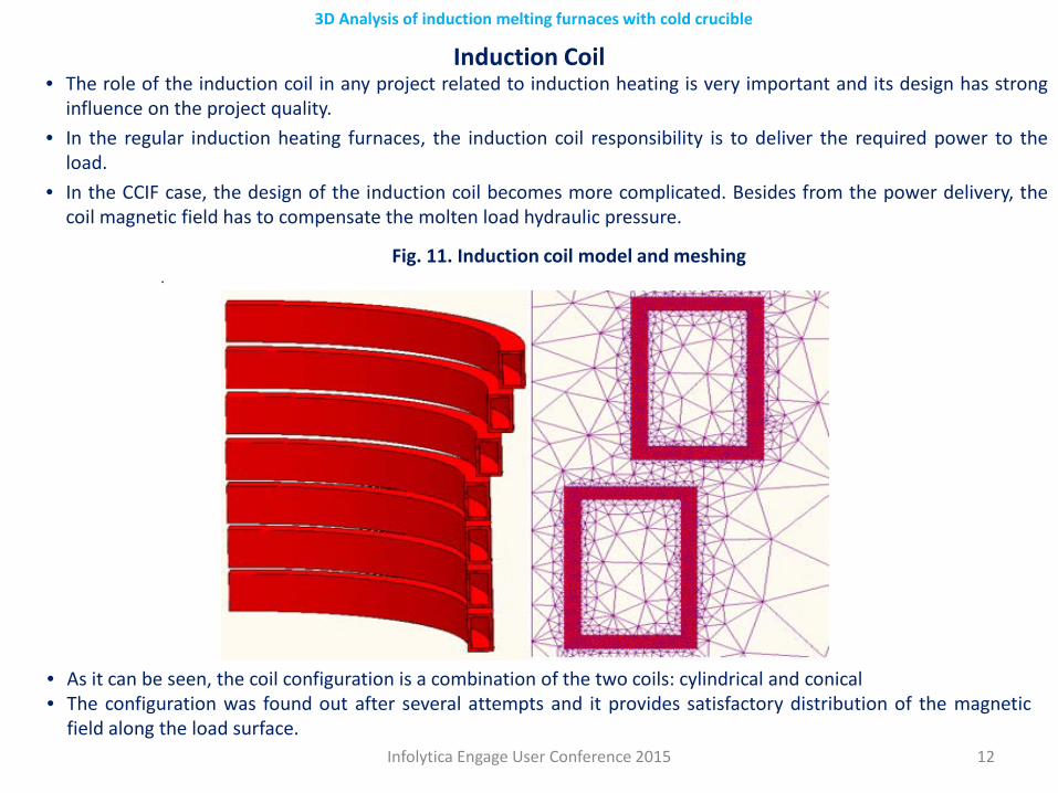
Induction Coil• The role of the induction coil in any project related to induction heating is very important and its design has strong
influence on the project quality.• In the regular induction heating furnaces, the induction coil responsibility is to deliver the required power to the
load.• In the CCIF case, the design of the induction coil becomes more complicated. Besides from the power delivery, the
coil magnetic field has to compensate the molten load hydraulic pressure.
• As it can be seen, the coil configuration is a combination of the two coils: cylindrical and conical• The configuration was found out after several attempts and it provides satisfactory distribution of the magnetic
field along the load surface.
Fig. 11. Induction coil model and meshing .
Infolytica Engage User Conference 2015 13
3D Analysis of induction melting furnaces with cold crucible
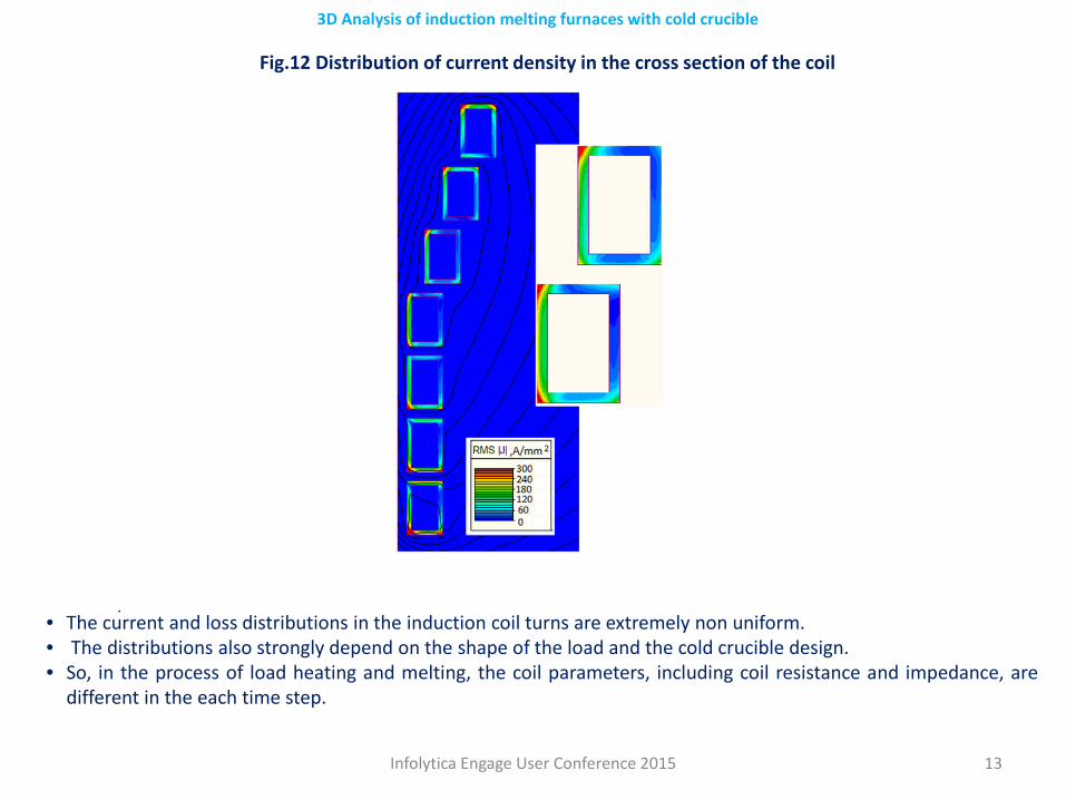
Fig.12 Distribution of current density in the cross section of the coil
• The current and loss distributions in the induction coil turns are extremely non uniform.• The distributions also strongly depend on the shape of the load and the cold crucible design.• So, in the process of load heating and melting, the coil parameters, including coil resistance and impedance, are
different in the each time step.
.
Infolytica Engage User Conference 2015 14
3D Analysis of induction melting furnaces with cold crucible
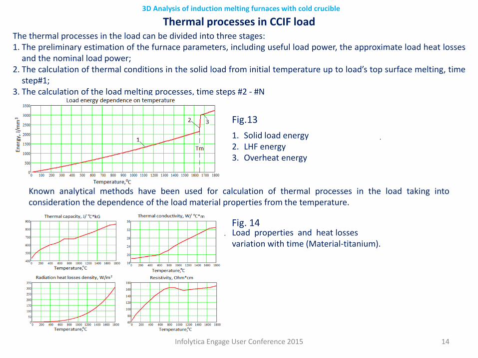
Thermal processes in CCIF loadThe thermal processes in the load can be divided into three stages: 1. The preliminary estimation of the furnace parameters, including useful load power, the approximate load heat losses
and the nominal load power;2. The calculation of thermal conditions in the solid load from initial temperature up to load’s top surface melting, time
step#1;3. The calculation of the load melting processes, time steps #2 - #N
• Fig. 13F Fig.13
Known analytical methods have been used for calculation of thermal processes in the load taking intoconsideration the dependence of the load material properties from the temperature.
1. Solid load energy2. LHF energy3. Overheat energy
Load properties and heat losses variation with time (Material-titanium).
.
Fig. 14.
Infolytica Engage User Conference 2015 15
3D Analysis of induction melting furnaces with cold crucible
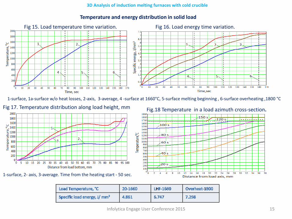
1-surface, 1a-surface w/o heat losses, 2-axis, 3-average, 4 -surface at 1660°C, 5-surface melting beginning , 6-surface overheating ,1800 °C
Temperature and energy distribution in solid load
Fig 15. Load temperature time variation.
Temperature distribution in a load azimuth cross-section.
Fig 17. Temperature distribution along load height, mm
1-surface, 2- axis, 3-average. Time from the heating start - 50 sec.
Fig 16. Load energy time variation.
Fig.18 Temperature in a load azimuth cross-section.
Infolytica Engage User Conference 2015 16
3D Analysis of induction melting furnaces with cold crucible
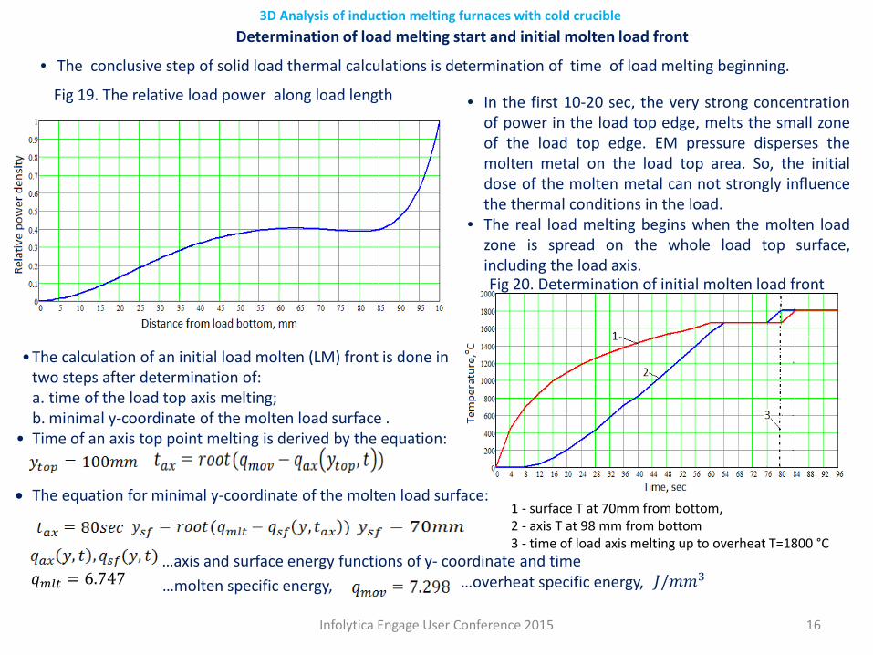
• The conclusive step of solid load thermal calculations is determination of time of load melting beginning.
Fig 19. The relative load power along load length
Determination of load melting start and initial molten load front
• In the first 10-20 sec, the very strong concentrationof power in the load top edge, melts the small zoneof the load top edge. EM pressure disperses themolten metal on the load top area. So, the initialdose of the molten metal can not strongly influencethe thermal conditions in the load.
• The real load melting begins when the molten loadzone is spread on the whole load top surface,including the load axis.Fig 20. Determination of initial molten load front
1 - surface T at 70mm from bottom, 2 - axis T at 98 mm from bottom3 - time of load axis melting up to overheat T=1800 °C
•The calculation of an initial load molten (LM) front is done in two steps after determination of:a. time of the load top axis melting; b. minimal y-coordinate of the molten load surface .
• Time of an axis top point melting is derived by the equation:
• The equation for minimal y-coordinate of the molten load surface:
𝐽𝐽/𝑚𝑚𝑚𝑚3…axis and surface energy functions of y- coordinate and time…molten specific energy,𝑞𝑞𝑚𝑚𝑚𝑚𝑚𝑚 = 6.747 …overheat specific energy,
Infolytica Engage User Conference 2015 17
3D Analysis of induction melting furnaces with cold crucible
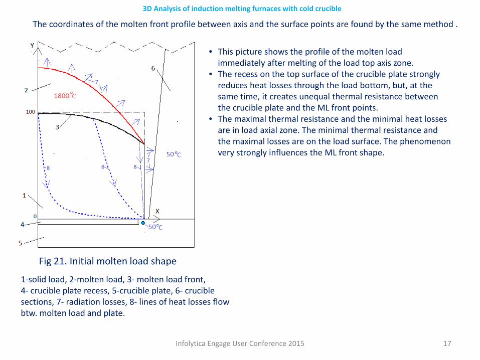
The coordinates of the molten front profile between axis and the surface points are found by the same method .
• This picture shows the profile of the molten load immediately after melting of the load top axis zone.
• The recess on the top surface of the crucible plate strongly reduces heat losses through the load bottom, but, at the same time, it creates unequal thermal resistance between the crucible plate and the ML front points.
• The maximal thermal resistance and the minimal heat losses are in load axial zone. The minimal thermal resistance and the maximal losses are on the load surface. The phenomenon very strongly influences the ML front shape.
1-solid load, 2-molten load, 3- molten load front,4- crucible plate recess, 5-crucible plate, 6- crucible sections, 7- radiation losses, 8- lines of heat losses flow btw. molten load and plate.
Fig 21. Initial molten load shape
Infolytica Engage User Conference 2015 18
3D Analysis of induction melting furnaces with cold crucible
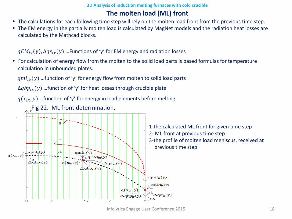
• The calculations for each following time step will rely on the molten load front from the previous time step.• The EM energy in the partially molten load is calculated by MagNet models and the radiation heat losses are
calculated by the Mathcad blocks.
1-the calculated ML front for given time step 2- ML front at previous time step3-the profile of molten load meniscus, received at
previous time step
Fig 22. ML front determination.
The molten load (ML) front
𝑞𝑞𝑞𝑞𝑞𝑞𝑖𝑖𝑖𝑖 𝑦𝑦 ,∆𝑞𝑞𝑞𝑞𝑖𝑖𝑖𝑖(𝑦𝑦) …Functions of ‘y’ for EM energy and radiation losses
• For calculation of energy flow from the molten to the solid load parts is based formulas for temperature calculation in unbounded plates.
𝑞𝑞𝑚𝑚𝑞𝑞𝑖𝑖𝑖𝑖(𝑦𝑦) …function of ‘y’ for energy flow from molten to solid load parts
∆𝑞𝑞𝑞𝑞𝑞𝑞𝑖𝑖𝑖𝑖(𝑦𝑦) …function of ‘y’ for heat losses through crucible plate
𝑞𝑞(𝑥𝑥𝑖𝑖𝑖𝑖,𝑦𝑦) …function of ‘y’ for energy in load elements before melting
Infolytica Engage User Conference 2015 19
3D Analysis of induction melting furnaces with cold crucible
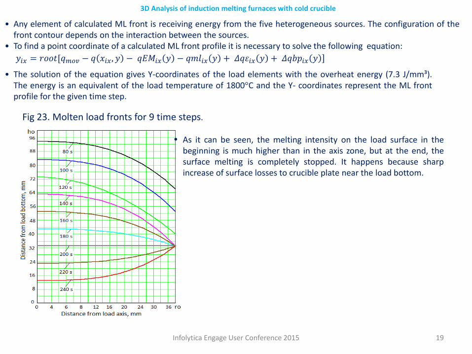
Fig 23. Molten load fronts for 9 time steps.
• Any element of calculated ML front is receiving energy from the five heterogeneous sources. The configuration of thefront contour depends on the interaction between the sources.
• To find a point coordinate of a calculated ML front profile it is necessary to solve the following equation:
• The solution of the equation gives Y-coordinates of the load elements with the overheat energy (7.3 J/mm³).The energy is an equivalent of the load temperature of 1800°C and the Y- coordinates represent the ML frontprofile for the given time step.
• As it can be seen, the melting intensity on the load surface in thebeginning is much higher than in the axis zone, but at the end, thesurface melting is completely stopped. It happens because sharpincrease of surface losses to crucible plate near the load bottom.
]𝑦𝑦𝑖𝑖𝑖𝑖 = 𝑟𝑟𝑟𝑟𝑟𝑟𝑟𝑟[𝑞𝑞𝑚𝑚𝑚𝑚𝑚𝑚 − 𝑞𝑞 𝑥𝑥𝑖𝑖𝑖𝑖,𝑦𝑦 − 𝑞𝑞𝑞𝑞𝑞𝑞𝑖𝑖𝑖𝑖 𝑦𝑦 − 𝑞𝑞𝑚𝑚𝑞𝑞𝑖𝑖𝑖𝑖 𝑦𝑦 + 𝛥𝛥𝑞𝑞𝑞𝑞𝑖𝑖𝑖𝑖 𝑦𝑦 + 𝛥𝛥𝑞𝑞𝑞𝑞𝑞𝑞𝑖𝑖𝑖𝑖 𝑦𝑦
Infolytica Engage User Conference 2015 20
3D Analysis of induction melting furnaces with cold crucible
Molten load meniscus calculation• The shape of the molten load front provides all the necessary data for the load meniscus calculation.• At first sight, the load meniscus calculation comes to finding out a molten load shape with hydraulic pressure that
would be equal to the EM pressure of the induction coil magnetic field.• In reality, the problem is complicated by the fact, that there are practically infinite number of shapes that satisfy the
condition of equality of hydraulic and electromagnetic pressure, but do not provide a number of technicalrequirements that is necessary for the normal work of the furnace.
• The following requirements are necessary to provide for the stable melting process:◦ The energy induced into the molten part by the induction coil has to be equal to the radiation losses from the
molten load surface and the energy transferred from the molten to solid loads;◦ To ensure stability of the meniscus, the electromagnetic pressure along the molten load part has to diminish
smoothly enough from the bottom to the top of meniscus;◦ To provide an acceptable power source utilization, it is essential to keep minimal ratio between the power in the
molten part and the total load, especially during the initial stage of the melting process• Taking into consideration all the above requirements, the calculation of the load meniscus do not have a simple
solution and requires an iteration approach.
Infolytica Engage User Conference 2015 21
3D Analysis of induction melting furnaces with cold crucible
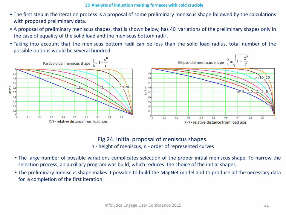
• The first step in the iteration process is a proposal of some preliminary meniscus shape followed by the calculationswith proposed preliminary data.
• A proposal of preliminary meniscus shapes, that is shown below, has 40 variations of the preliminary shapes only inthe case of equality of the solid load and the meniscus bottom radii .
• Taking into account that the meniscus bottom radii can be less than the solid load radius, total number of thepossible options would be several hundred.
Fig 24. Initial proposal of meniscus shapes.h - height of meniscus, n - order of represented curves
• The large number of possible variations complicates selection of the proper initial meniscus shape. To narrow theselection process, an auxiliary program was build, which reduces the choice of the initial shapes.
• The preliminary meniscus shape makes it possible to build the MagNet model and to produce all the necessary datafor a completion of the first iteration.
Infolytica Engage User Conference 2015 22
3D Analysis of induction melting furnaces with cold crucible
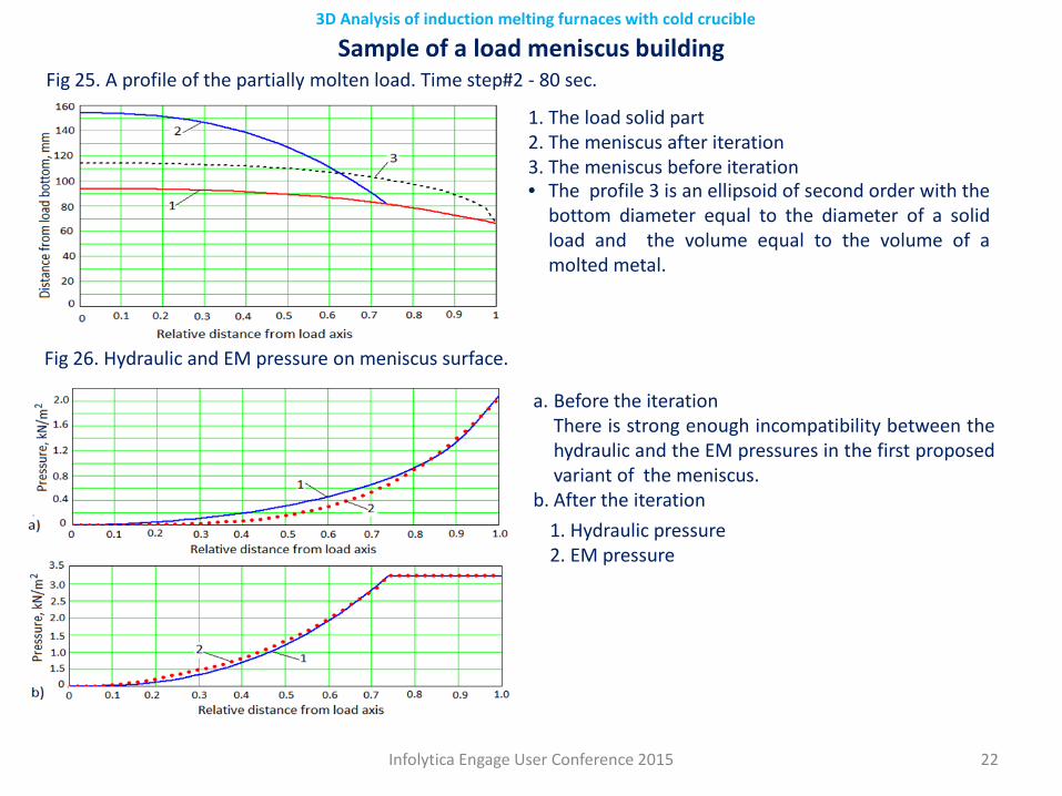
Sample of a load meniscus building
1. The load solid part 2. The meniscus after iteration 3. The meniscus before iteration• The profile 3 is an ellipsoid of second order with the
bottom diameter equal to the diameter of a solidload and the volume equal to the volume of amolted metal.
Fig 25. A profile of the partially molten load. Time step#2 - 80 sec.
Fig 26. Hydraulic and EM pressure on meniscus surface.
a. Before the iteration There is strong enough incompatibility between thehydraulic and the EM pressures in the first proposedvariant of the meniscus.
b. After the iteration1. Hydraulic pressure 2. EM pressure
Infolytica Engage User Conference 2015 23
3D Analysis of induction melting furnaces with cold crucible
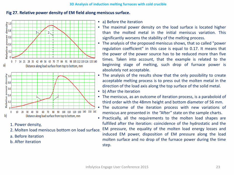
1. Power density, 2. Molten load meniscus bottom on load surface.
Fig 27. Relative power density of EM field along meniscus surface.
a. Before iteration b. After iteration
• a) Before the iteration• The maximal power density on the load surface is located higher
than the molted metal in the initial meniscus variation. Thissignificantly worsens the stability of the melting process.
• The analysis of the proposed meniscus shows, that so called "powerregulation coefficient" in this case is equal to 0.17. It means thatthe power of the power source has to be reduced more than fivetimes. Taken into account, that the example is related to thebeginning stage of melting, such drop of furnace power isabsolutely not acceptable.
• The analysis of the results show that the only possibility to createacceptable melting process is to press out the molten metal in thedirection of the load axis along the top surface of the solid metal.
• b) After the iteration• The meniscus, as an outcome of iteration process, is a paraboloid of
third order with the 48mm height and bottom diameter of 56 mm.• The outcome of the iteration process with new variations of
meniscus are presented in the “After” state on the sample charts.• Practically, all the requirements to the molten load shapes are
fulfilled after the iteration: coincidence of the hydrostatic and theEM pressure, the equality of the molten load energy losses andinduced EM power, disposition of EM pressure along the loadmolten surface and no drop of the furnace power during the timestep.
Infolytica Engage User Conference 2015 24
3D Analysis of induction melting furnaces with cold crucible
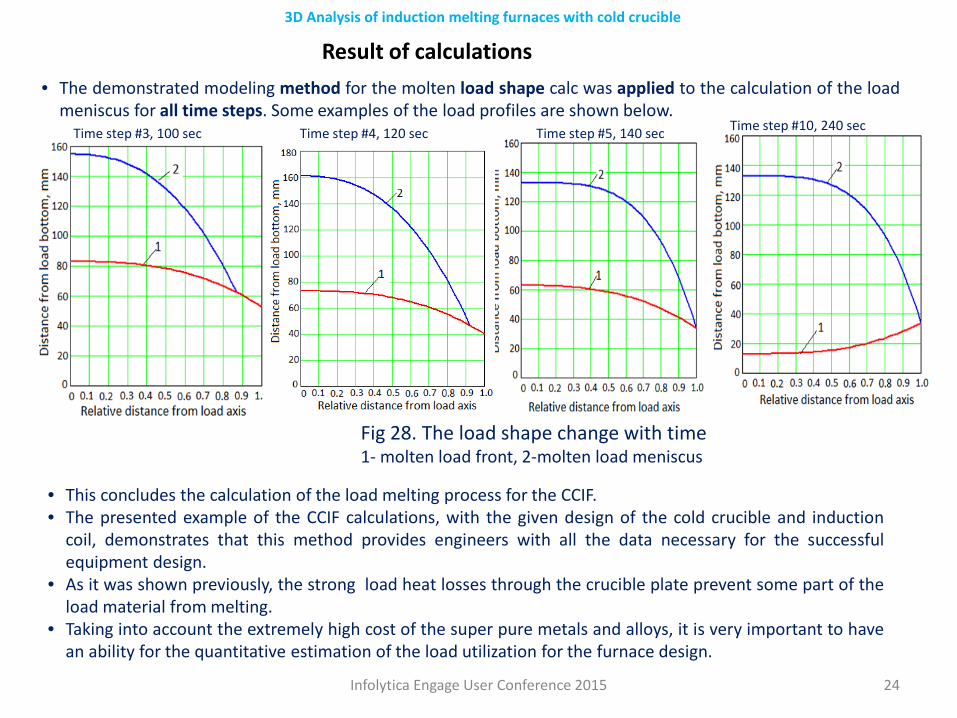
Fig 28. The load shape change with time1- molten load front, 2-molten load meniscus
• The demonstrated modeling method for the molten load shape calc was applied to the calculation of the loadmeniscus for all time steps. Some examples of the load profiles are shown below.
Time step #3, 100 sec Time step #4, 120 sec Time step #5, 140 sec Time step #10, 240 sec
Result of calculations
• This concludes the calculation of the load melting process for the CCIF.• The presented example of the CCIF calculations, with the given design of the cold crucible and induction
coil, demonstrates that this method provides engineers with all the data necessary for the successfulequipment design.
• As it was shown previously, the strong load heat losses through the crucible plate prevent some part of theload material from melting.
• Taking into account the extremely high cost of the super pure metals and alloys, it is very important to havean ability for the quantitative estimation of the load utilization for the furnace design.
Infolytica Engage User Conference 2015 25
3D Analysis of induction melting furnaces with cold crucible
Conclusion.The represented calculation method of the induction cold crucible furnaces for super cleanmelting allows to design the furnaces without contact between the molten metal and the furnacecrucible in the process of melting, which in return dramatically reduces the contamination of thefurnace output.
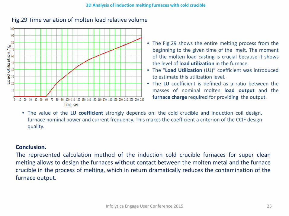
Fig.29 Time variation of molten load relative volume
• The Fig.29 shows the entire melting process from thebeginning to the given time of the melt. The momentof the molten load casting is crucial because it showsthe level of load utilization in the furnace.
• The “Load Utilization (LU)” coefficient was introducedto estimate this utilization level.
• The LU coefficient is defined as a ratio between themasses of nominal molten load output and thefurnace charge required for providing the output.
• The value of the LU coefficient strongly depends on: the cold crucible and induction coil design,furnace nominal power and current frequency. This makes the coefficient a criterion of the CCIF designquality.