Embed Size (px)
Citation preview

3D Pro
User Guide The 3-D Pro will only operate as instructed.
Please make sure that the correct cutter and jaw combination are in place before cutting the key!!!!
It is recommended that Safety Glasses be worn at all times when operating this machine.

Table of Contents (Clicking takes you to that page)
CHECKING YOUR NEW 3D PRO 2
COMPUTER HARDWARE REQUIREMENTS 2
THE EMERGENCY STOP BUTTON 3
SOFTWARE INSTALLATION 3
MAKING YOUR COMPUTER RECOGNIZE YOUR 3-D PRO 4
FINDING THE CORRECT COM PORT 4
ERROR CONNECTING 5
CHANGING THE CUTTER OR STYLUS 6
CHANGING TRACER 7
USING JAW 1 8
CLAMPING HIGH SECURITY KEYS THAT REQUIRE “ADAPTERS” 10
USING JAW 2 11
CALIBRATING YOUR 3D PRO 14
CUTTING A KEY “COMMERCIAL/DOMESTIC” 18
CUTTING A KEY “AUTOMOTIVE” 20
SPACE AND DEPTH ADJUSTMENTS 21
SHOW KEY INFORMATION 28
EXPLAINING THE SOFTWARE, BUTTONS, TABS, BOXES AND DROP DOWN MENUS 29
USING THE EDIT SCREEN 32
USING THE SETUP SCREEN - READ FROM PC 34
HOW TO UPDATE SOFTWARE 35
TROUBLESHOOTING 35
EXAMPLE OF INVERTER CHASSIS GROUNDING 38
CHANGING THE FUSES 38

Page 2 of 40
Checking your new 3D Pro Thank you for purchasing the 3-D Pro …. Please check for any damages caused during shipping, if any damage is found, please report it immediately. If damage is not reported on the day of arrival, the customer will be responsible for any repair costs. Don’t calibrate the machine; it is preset from the factory.
• Make sure the plastic covers on the 3D Pro are not cracked or broken. • Check that the tracer swing arm flips up and down properly • The machine should have no major scratches or markings • All missing parts should be reported upon day of arrival
Contents 1 x 3-D Pro Machine 1 x Jaw 1 (High security Jaw) 1 x Jaw 2 (Standard Jaw) 1 x Jaw 3 (VW Jaw) 1 x TR 2.5 Single Ended Cutter
1 x Stylus 1 x Tip Stop 1 x USB Cable 1 x AC Power Cord
Optional Parts: Bolt-Down Kit - Laptop Mount - Tibbe Adapter - Jaw Holder The 9 pin serial cable exiting the left side of the machine case should only be plugged into the 9 pin serial plug on the left side of the X table. (see pics below) Be sure to tighten down the two small flathead attaching screws. Do not plug the 9 pin serial cable into a computer, this will short out the control board.
Computer Hardware Requirements • Windows XP - SP2 or higher, Windows Vista, and Windows 7 with 512Mb of RAM • We recommend a 2,000 watt pure sine wave inverter is recommended to extend the life of your 3D Pro and laptop. • If using an inverter to power the 3D Pro, make sure the inverter is properly grounded to the vehicles chassis otherwise you may incur problems with the operation of the machine.
Page 3 of 40
When cleaning key shavings from the machine, please use a brush, please do not use compressed air as doing so will likely blow shavings into the machine over time causing problems such as gumming up the axis’ to where the tables could seize up or cause electrical shorts.
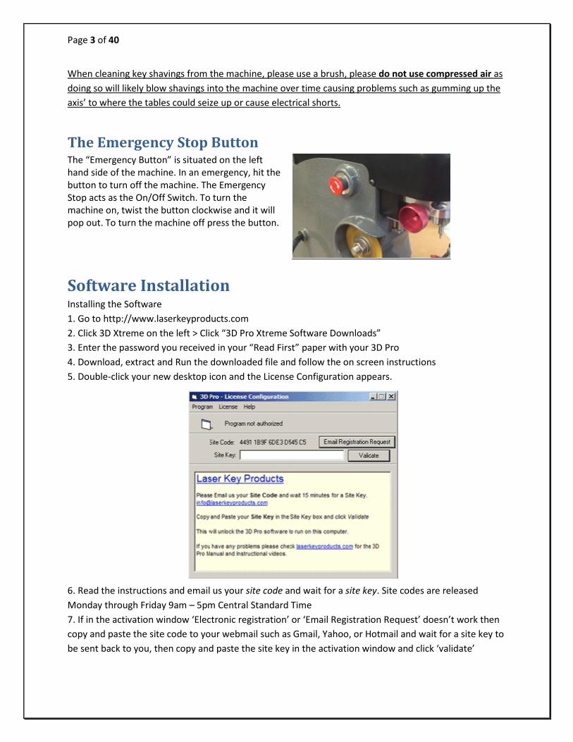
The Emergency Stop Button The “Emergency Button” is situated on the left hand side of the machine. In an emergency, hit the button to turn off the machine. The Emergency Stop acts as the On/Off Switch. To turn the machine on, twist the button clockwise and it will pop out. To turn the machine off press the button.
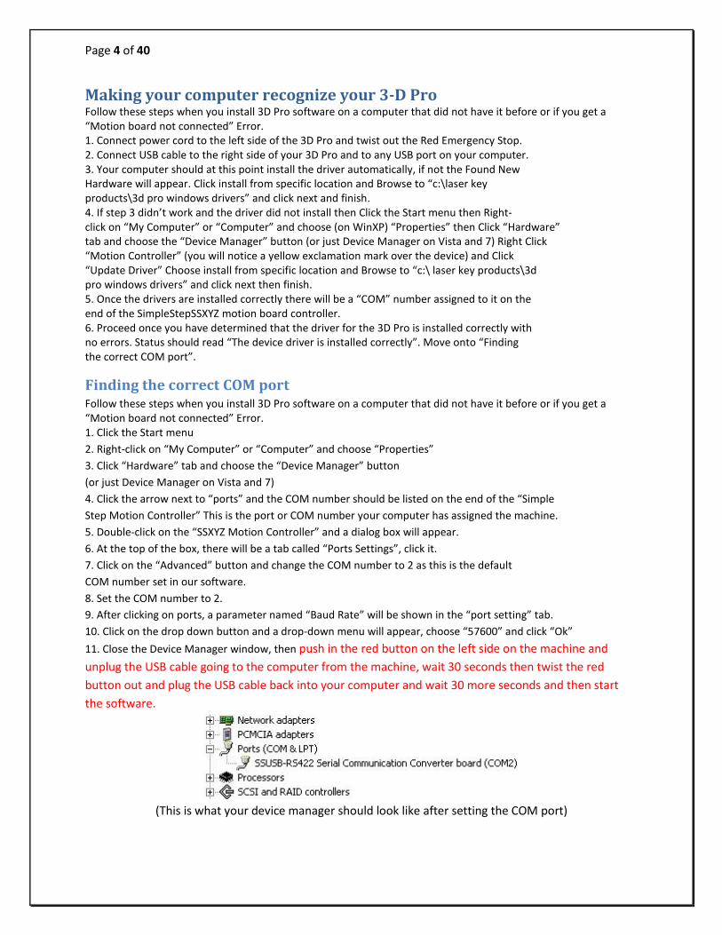
Software Installation Installing the Software 1. Go to http://www.laserkeyproducts.com 2. Click 3D Xtreme on the left > Click “3D Pro Xtreme Software Downloads” 3. Enter the password you received in your “Read First” paper with your 3D Pro 4. Download, extract and Run the downloaded file and follow the on screen instructions 5. Double-click your new desktop icon and the License Configuration appears.
6. Read the instructions and email us your site code and wait for a site key. Site codes are released Monday through Friday 9am – 5pm Central Standard Time 7. If in the activation window ‘Electronic registration’ or ‘Email Registration Request’ doesn’t work then copy and paste the site code to your webmail such as Gmail, Yahoo, or Hotmail and wait for a site key to be sent back to you, then copy and paste the site key in the activation window and click ‘validate’
Page 4 of 40
Making your computer recognize your 3-D Pro Follow these steps when you install 3D Pro software on a computer that did not have it before or if you get a “Motion board not connected” Error. 1. Connect power cord to the left side of the 3D Pro and twist out the Red Emergency Stop. 2. Connect USB cable to the right side of your 3D Pro and to any USB port on your computer. 3. Your computer should at this point install the driver automatically, if not the Found New Hardware will appear. Click install from specific location and Browse to “c:\laser key products\3d pro windows drivers” and click next and finish. 4. If step 3 didn’t work and the driver did not install then Click the Start menu then Right- click on “My Computer” or “Computer” and choose (on WinXP) “Properties” then Click “Hardware” tab and choose the “Device Manager” button (or just Device Manager on Vista and 7) Right Click “Motion Controller” (you will notice a yellow exclamation mark over the device) and Click “Update Driver” Choose install from specific location and Browse to “c:\ laser key products\3d pro windows drivers” and click next then finish. 5. Once the drivers are installed correctly there will be a “COM” number assigned to it on the end of the SimpleStepSSXYZ motion board controller. 6. Proceed once you have determined that the driver for the 3D Pro is installed correctly with no errors. Status should read “The device driver is installed correctly”. Move onto “Finding the correct COM port”.
Finding the correct COM port Follow these steps when you install 3D Pro software on a computer that did not have it before or if you get a “Motion board not connected” Error. 1. Click the Start menu 2. Right-click on “My Computer” or “Computer” and choose “Properties” 3. Click “Hardware” tab and choose the “Device Manager” button (or just Device Manager on Vista and 7) 4. Click the arrow next to “ports” and the COM number should be listed on the end of the “Simple Step Motion Controller” This is the port or COM number your computer has assigned the machine. 5. Double-click on the “SSXYZ Motion Controller” and a dialog box will appear. 6. At the top of the box, there will be a tab called “Ports Settings”, click it. 7. Click on the “Advanced” button and change the COM number to 2 as this is the default COM number set in our software. 8. Set the COM number to 2. 9. After clicking on ports, a parameter named “Baud Rate” will be shown in the “port setting” tab. 10. Click on the drop down button and a drop-down menu will appear, choose “57600” and click “Ok” 11. Close the Device Manager window, then push in the red button on the left side on the machine and unplug the USB cable going to the computer from the machine, wait 30 seconds then twist the red button out and plug the USB cable back into your computer and wait 30 more seconds and then start the software.
(This is what your device manager should look like after setting the COM port)

Page 5 of 40
Error Connecting If you’re experiencing connection problems and have already performed the above steps then go to ‘c:\Laser Key Products\CommSetup’ folder. Then copy and paste the CommSetup text file into the ‘c:\Laser Key Products’ Directory. Make sure your comm port is set to ‘2’ with a baud rate of 57600. In the CommSetup.txt file the bottom 2 lines should read ‘2’ and ‘57600’ The number second from bottom in the CommSetup.txt file determines which COM port should be used in the device manager. COM Error If you start your software and the software says “Communications Error” or “Board Not Found” check these options: 1. Power is going to your 3D Pro from the power outlet. 2. The emergency stop button is disengaged (twisted out according to the arrows) 3. The USB cable from the 3D Pro is plugged into a USB port on your computer. 4. Multiple instances of the 3D Pro software may be running causing a conflict. Open Task Manager by pressing Control Alt Delete on your keyboard and then clicking Task Manager. Look for ‘3D Pro Xtreme.exe’, click it, then click “End Process” Then start the 3D Pro software again.

Page 6 of 40
If you still get error connecting right click the desktop icon for the 3D Pro then click the compatibility tab and set the setting shown below.
Changing the Cutter or Stylus “The Collet” Holds the Cutter or Stylus in the spindle. To remove the cutter or stylus, first hold the red knurl knob on the top of the machine sticking up through the lid. Then press in “spindle stop button” on the front of the head unit. Now turn the knob on top with your hand until you feel the spindle stop button press all the way in. Turn the knob counter clockwise and you will feel the collet loosen. The cutter or stylus can now be removed. Machines that do not have the “spindle stop button” will have a red “knurl knob” underneath the head unit that you will use together with the top knurl knob to loosen the “Collet” and remove the cutter.

Page 7 of 40
When replacing the cutter or stylus, insert it into the collet and slide it up until it stops. Press the spindle stop button in until it catches so you can tighten the collet back up on the cutter, it does not have to be extremely tight, hand tight should be sufficient. If one of the ends of your TR62.2 double ended Jaw 2 cutter is broken, you will notice that it inserts further into the collet than normal. This is fine but if it had just broke be sure to click on “Enter” before clicking on the “Start” button so it will compensate for the new length. Pressing the “Enter” button causes the machine to recalculate the cutting path.
Changing Tracer When changing the tracer, tighten the set screw that holds the tracer tip in place in between the two dimples.

Page 8 of 40
Changing Jaws The black Jaw 1 is for High Security keys and the silver Jaw 2 is for standard security keys. When changing a jaw, look behind where the jaw is attached, you will notice a red “T knob” Turn the “T knob” counter clockwise to release the lock pin, the jaw can be now be removed from the table by sliding it off to the right. Replacing the jaw is the same operation in reverse order, if the jaw will not slide into place, make sure the angle of the lock pin matches the angle of the dovetail, and lock pin is not protruding (like the one in the pic)
USING JAW 1 Clamping High Security Keys in Jaw 1 Using the “Tip Stop” When you select a High Security key, the software will tell you which slot to place the “Tip Stop” After you have selected the high security key, look under the “Step 2” column on the home screen, you will find the tip stop number next to the box labeled “Stop”. It will read “Tip 1”, “Tip 2”, or “Tip 3” Now place the tip stop in the correct slot, lay the key flat in the jaw and slide the key forward until it touches the tip stop then tighten the jaw. Warning: Do not forget to remove the tip stop before tracing or cutting a key.

Page 9 of 40
Clamping High Security Keys in Jaw 1 Using the “Shoulder Stop” When selecting a key that calls for a “Shoulder” stop, place the key in the jaw and slide it forward until the shoulder of the key is touching the front of the jaw. No tip stop is used for this type of key. Tighten the red knob to lock the key in place.

Page 10 of 40
“Jaw1” is always used for ALL high security (laser style keys) except VW
The Cutter used with Jaw1 is always the TR2.5 single ended cutter
This is the “Tip Stop”
Clamping High Security Keys that use Adapters “Jaw 3” “VW” Adaptor (Jaw 3) When a VAG (HU66) key is selected, it requires the “VW” Adapter to be used. Open Jaw 1 wider than you normally would to allow the adaptor to be inserted; it should slide in easily and fit on the left side of the jaw. Slide it forward until the adapter stops and will push forward no further, see fig A.1 Now insert the key into the adapter and slide the key forward until the shoulder of the key stops on the adapter. The key will be on the right side of this adapter once clamped in the jaw.

Page 11 of 40
“B” Side When a Mercedes 2 Track key is selected, it requires that the “M” adapter be used. Open Jaw 1 wider than you normally would to allow the adaptor to be inserted, it should slide in the right, or moveable side of Jaw 1 and you will notice that there is a slot on the right side that the adapter slides into, see fig A.3 The adaptor will be on the right side of the key once clamped. Note: When using this adaptor you will also need to use the tip stop in “Tip Stop 2” (slot 2)
When a BMW HU92 2 Track key is selected it requires that the “B” adapter be used. Open Jaw 1 wider than you normally would to allow the adaptor to be inserted; it should slide in the slot on the “right” or moveable side of the Jaw, see fig B.1 The adapter will be on the right side of the key once clamped, see fig B.2 Note: When using this adaptor you will also need to use the “Tip Stop” in tip stop 2 (slot 2)
USING JAW 2
Changing Jaw Clamp
To change which jaw clamp faces the cutting wheel all you have to do is loosen the jaw 2 and firmly twist the jaw 2 in any direction until the desired jaw clamp is facing the cutting wheel.

Page 12 of 40
Clamping Non-High Security “Shoulder Stop” Keys in Jaw 2
When you select a standard security key from the menu, the software will tell you which “Stop” to use, “Shoulder” or “Tip” This is an example of a Shoulder Stop key. Slide the key forward until it stops on the shoulder of the key. Tighten the red knob on top until the key is clamped firmly.
Clamping Non-High Security “Tip Stop” Keys in Jaw 2 This is an example of a Tip Stop key. Insert the key into the jaw and raise the “Tip Stop” slide the key forward until it touches on the stop.
Remember to fold the “Shoulder” or “Tip” Stop back down before you start to “Trace” or “Cut” a key

Page 13 of 40
Be sure that all keys are inserted completely into the back (bottom) of the Jaw unless otherwise specified in the text box on bottom of the home screen. The message will appear once the key is selected, if there are any notes like “clamp key on milling” it will appear here.
Circled in RED is the milling of this Y157 Key. It is the thinest part of the key along the edge.
Cut Types
Slotted Cuts are not available at this time.
Laser Cut
Plunge Cut
When tracing or cutting the second side of a double sided key, if there are no 1 depths towards the tip of the key it will not automatically align in the jaw. To keep the key correctly aligned in the jaw, you must align the key by eye. The best way to do this is compare the milling marks on the key to the straight edge of the jaw.

Page 14 of 40
Calibrating your 3D Pro If you get “Obstruction Detected” errors you may need to calibrate, make sure you are calibrating with the stylus and not the cutter.
Calibrating Cutter for Jaw 1 1. Clean any shavings or debris from jaw (Any metal shavings, dirt or grease that the stylus touches will take an incorrect reading). And open Jaw 1 all the way!
2. Put the Stylus in the collet. The Stylus must be used to calibrate. Do not use cutters to calibrate or else your keys will cut wrong.
This is the Stylus.
3. Make sure the tracer arm is up, if the tracer arm is down, you will receive an error message. 4. On the main screen, click on the “Operations” menu and choose “Calibrate Machine”
5. When the window appears asking to “Select Jaw” insert the correct jaw number in the window, 1 (1, 2, or 3 depending on which jaw you want to calibrate) as we are calibrating Jaw “1” we would enter “1” and click “OK”
6. The stylus will touch the jaw in three places. After the procedure is complete it will say “Update in Progress Please Wait” give it a moment and don’t click anything or it can possibly freeze the software and you will have to restart it.
Calibrating Tracer for Jaw 1
1. Always have a “Cutter” or “Stylus” installed while calibrating the Tracer, do not leave the collet empty or it will get in the way of the Tracer. 2. Flip the tracer arm down with the “red knurl knob” on the left side of the head. 3. On the main screen, click on the “Operations” menu and choose “Calibrate Tracer” 4. When the window appears asking to “Select Jaw” insert the correct jaw number in the window,
Page 15 of 40
(1, 2, or 3 depending on which jaw you want to calibrate) as we are calibrating Jaw “1” we would enter “1” and click “OK” 5. The tracer tip will touch the jaw in three places. After the procedure is complete it will read, “Update in Progress Please Wait” give it a moment and don’t click anything or it can possibly freeze the software and you will have to restart it.
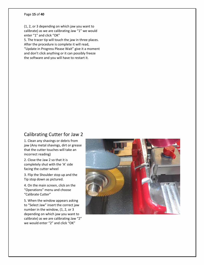
Calibrating Cutter for Jaw 2 1. Clean any shavings or debris from jaw (Any metal shavings, dirt or grease that the cutter touches will take an incorrect reading)
2. Close the Jaw 2 so that it is completely shut with the ‘A’ side facing the cutter wheel
3. Flip the Shoulder stop up and the Tip stop down as pictured.
4. On the main screen, click on the “Operations” menu and choose “Calibrate Cutter”
5. When the window appears asking to “Select Jaw” insert the correct jaw number in the window, (1, 2, or 3 depending on which jaw you want to calibrate) as we are calibrating Jaw “2” we would enter “2” and click “OK”

Page 16 of 40
6. The cutter wheel touches the front of the A side of the Jaw 2 and then moves to the left and touches the shoulder stop then goes home. After the procedure is complete it will read “Update in Progress Please Wait” give it a moment and don’t click anything or it can possibly freeze the software and you will have to restart it.
Jaw 2 may need minor adjustments to space or depth after calibrating to be correct. Refer to the section “Checking and Adjusting the “Tracer” for instructions.
There is no tracing for J2 at this time.
Calibrating Cutter for Jaw 3
1. Clean any shavings or debris from jaw (Any metal shavings, dirt or grease that the stylus touches will take an incorrect reading). And open Jaw all the way!
2. Put the Stylus in the collet. The Stylus must be used to calibrate. Do not use cutters to calibrate or else your keys will cut wrong.
3. Make sure the tracer arm is up, if the tracer arm is down, you will receive an error message.
Page 17 of 40
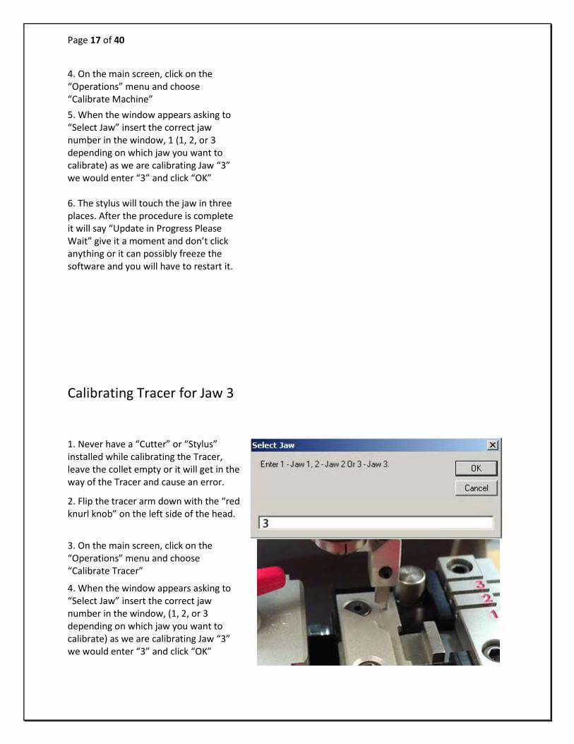
4. On the main screen, click on the “Operations” menu and choose “Calibrate Machine” 5. When the window appears asking to “Select Jaw” insert the correct jaw number in the window, 1 (1, 2, or 3 depending on which jaw you want to calibrate) as we are calibrating Jaw “3” we would enter “3” and click “OK” 6. The stylus will touch the jaw in three places. After the procedure is complete it will say “Update in Progress Please Wait” give it a moment and don’t click anything or it can possibly freeze the software and you will have to restart it. Calibrating Tracer for Jaw 3
1. Never have a “Cutter” or “Stylus” installed while calibrating the Tracer, leave the collet empty or it will get in the way of the Tracer and cause an error.
2. Flip the tracer arm down with the “red knurl knob” on the left side of the head.
3. On the main screen, click on the “Operations” menu and choose “Calibrate Tracer”
4. When the window appears asking to “Select Jaw” insert the correct jaw number in the window, (1, 2, or 3 depending on which jaw you want to calibrate) as we are calibrating Jaw “3” we would enter “3” and click “OK”

Page 18 of 40
5. The tracer tip will touch the jaw in three places. After the procedure is complete it will read, “Update in Progress Please Wait” give it a moment and don’t click anything or it can possibly freeze the software and you will have to restart it.
Cutting a Key “Commercial/Domestic” 1) “Select Manufacturer” The “Select Manufacturer” box will have an “Arrow Down” key that you must click. Pressing any letter at this point will jump directly to all the manufacturers listed starting with that letter, for example, pressing the letter “S” will pull up all entries beginning with “S” In this example I have used SCHLAGE choosing this will open a box showing all the relevant keys (in the database) for this manufacturer.
2) “Click on the Key Blank below”

Page 19 of 40
Click on the key blank you want and it will open the “Main” cutting information window. The “Main” section gives us all the information we need to cut the key.
3) “Enter depths and click “Enter” Enter the depth of your cuts starting with “1” as the cut nearest the shoulder of the key. Once the cuts have been entered click “Enter”
4) “Click on “Start” to cut the key” Once you have entered the cuts, click “Enter” and the “Start” button will appear, click on the start button and you will see a check box “Click OK if Jaw 2 and TR62 cutter installed" If you have the correct jaw and cutter installed, click “OK” to cut the key.
Page 20 of 40
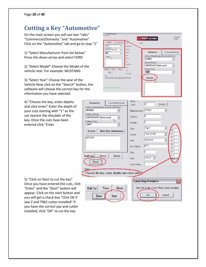
Cutting a Key “Automotive” On the main screen you will see two “tabs” “Commercial/Domestic ”and “Automotive” Click on the “Automotive” tab and go to step “1” 1) “Select Manufacturer from list below” Press the down arrow and select FORD 2) “Select Model” Choose the Model of the vehicle next. For example: MUSTANG 3) “Select Year” Choose the year of the Vehicle Now click on the “Search” button, the software will choose the correct key for the information you have selected. 4) “Choose the key, enter depths and click enter” Enter the depth of your cuts starting with “1” as the cut nearest the shoulder of the key. Once the cuts have been entered click “Enter
5) “Click on Start to cut the key” Once you have entered the cuts, click “Enter” and the “Start” button will appear. Click on the start button and you will get a check box “Click OK if Jaw 2 and TR62 cutter installed" If you have the correct jaw and cutter installed, click “OK” to cut the key.

Page 21 of 40
SPACE AND DEPTH ADJUSTMENTS The following pages will show you how to check and set your machine to cut and trace perfectly. Explaining the X, Y, Z Axis 1. This machine has three axes which are X, Y, and Z 2. The X axis is the movement from left and right and controls the depth. 3. The Y axis is the movement from front to back and controls the spacing. 4. The Z axis is the movement up and down and controls the height at which the cutter is lower
How to use “Space/Depth Adjustment” All adjustments are in .001” (one thousandths of an inch) The “Space” or “Depth” on either the “Tracer” or the “Cutter” can be adjusted by a maximum of “.020” (20 thousands) either way (+ or -) plus or minus.
To make any of these adjustments, go to “Operations” and choose “Space Depth Adjustment” on the drop down menu and this will open the “Select Jaw” box.
Enter the “Jaw” you are intending to make adjustments to, in this example I have entered “2” for Jaw 2. Now click “OK” and the “Space and Depth Adjustments” box will open
As you will see we can choose “Cutter” or “Tracer” and also we can choose “Space” or “Depth” offset. By changing the value from “0” we can adjust the depth or spacing on both the cutter and the tracer. When we change the values here we are in fact adjusting where the “cutter” or “tracer” makes contact with the key.
If we want to make the cutter cut deeper we would enter a minus number (-) in the Depth Offset box. To cut the key “.005” (5 thou) deeper we would enter “–5” in the “Depth Offset” box.
To cut less -5 material off the key and make the cut .005 thicker we would enter “5”

Page 22 of 40
To make the cutter cut closer to the shoulder of the key we would enter a minus number (-) in the “Space Offset” box. To cut the key .005 closer to the shoulder of the key you would enter “–5” in the “Space Offset” box. To cut the key .005 closer to the tip of the key you would enter “5” in the “Space Offset” box.
You will see that the “Space and Depth Adjustments” box is marked with (+ or -) plus or minus on both Space and Depth.
Checking and Adjusting the Depth settings on Jaw 2 Set the software to cut a key to “Schlage” DSD 19 this is this is the Schlage 5 pin blank, Instacode shows the “1” (one) depth to be “.320” (320 thou) Enter all the cuts as “1” and cut the key
Once the key is cut, read the key “Depth” with a “caliper” to see if it reads “.320” if it does then your depth setting is correct, if not you will have to make some slight adjustments.
When I cut my key I got a reading of “.324” … This is “.004” higher than it should be, so I need to make the software cut the key “.004” deeper.
To make this adjustment go to “Operations” and choose “Space Depth Adjustment” In the “Select Jaw” type ‘2’ and click “OK”
Now change the value in the “Depth Offset” to “-4” and click “Update” You will see a message “Update in progress, please do not turn OFF system”
Wait until you see: “Update complete” and
then click “OK”
Page 23 of 40
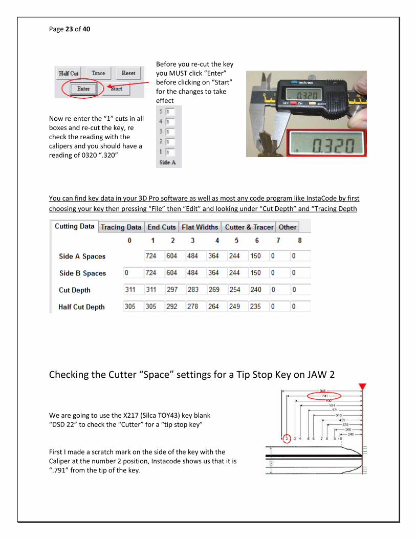
Before you re-cut the key you MUST click “Enter” before clicking on “Start” for the changes to take effect
Now re-enter the “1” cuts in all boxes and re-cut the key, re check the reading with the calipers and you should have a reading of 0320 “.320”
You can find key data in your 3D Pro software as well as most any code program like InstaCode by first choosing your key then pressing “File” then “Edit” and looking under “Cut Depth” and “Tracing Depth
Checking the Cutter “Space” settings for a Tip Stop Key on JAW 2
We are going to use the X217 (Silca TOY43) key blank “DSD 22” to check the “Cutter” for a “tip stop key” First I made a scratch mark on the side of the key with the Caliper at the number 2 position, Instacode shows us that it is “.791” from the tip of the key.

Page 24 of 40
Enter the cuts 1-3-1-1-1-1-1-1-1-1 and cut the key…
If the cut is not in the center of the mark, you will have to make some slight adjustments. Go to “Operations” and choose “Space Depth Adjustment” on the drop box, select “Jaw2” and click “OK”
To cut the key .005 closer to the “shoulder” of the key … enter “–5” (minus 5) in the “Space Offset” box (under cutter)
To cut the key .005 closer to the “tip” of the key … enter “5” in the “Space Offset” box. When you have made your changes, click “Update” You will see a message “Update in progress, please do not turn OFF system” Wait until you see: “Update complete” and then click “OK”
Before you re-cut the key you MUST click “Enter” before clicking on “Start” for the changes to take effect
You might want to re-check you depth settings by reading the depth of the number 3 cut with the calipers. The depth should read 0.272 “.272”

Page 25 of 40
Checking the Tracer “Space” settings for a Tip Stop Key on JAW 2 We are going to use the X217 (Silca TOY43) key blank that we marked and cut earlier to check the “Tracer” for a “tip stop key”
Set the software to X217 (Silca TOY43) “DSD 22” and clamp the key in Jaw 2 and click on the “Trace” button. Now watch the tracer as it moves along the key and see if it drops in the “center” of the number 2 cut, I noticed that the tracer on mine did not drop in the center of the number 2 cut BUT it dropped too close to the head of the key. To make the tracer tip drop into the center of the cut we need to make some adjustments. Go to “Operations” and choose “Space Depth Adjustment” on the drop box select “Jaw2”
and click “OK”. Now change the value in the “Space Offset” on the tracer to “2” to bring the center of the tracer “.002” (2 thou) closer to the tip of the key, then click “Update”
You will see a message “Update in progress, please do not turn OFF system”. Wait until you see: “Update complete” and then click “OK” … Now trace the key again.
I found that the tracer was still dropping too close to the head of the key so I changed the offset to “4”, then click “Update” again and wait 4 until you see: “Update complete” and -4 then click “OK” I traced again and this time the tracer was perfectly in the center of the cut.
Your 3-D Pro should now be Calibrated perfectly for Cutting and Tracing on JAW2 Tip Stop
Checking the “Cutter” settings for a Shoulder Stop Key on JAW 2

Page 26 of 40
We are going to use a Schlage to check the “Cutter” for a “shoulder stop key” Now check to see what Instacode shows for the “2nd” space on a Schlage key. As shown, space two is “.387” (387 thou) from the shoulder of the key. Set the software to cut a key to “Schlage” DSD 19 settings. Enter the cuts as 0-2-0-0-0 and cut the key

Page 27 of 40
The shoulder stop should be flush with the edge of the pocket which is cut into the corner of the jaw. If you flip the shoulder stop up you can tell if it has been slightly bent forward, if it has you will want to bend it back to match the edge of the jaw pocket. Use a small “Crescent Wrench” to do this; by tightening the Crescent onto the Shoulder Stop you have a lot of control while bending.
Checking the “Tracer” settings for Shoulder Stop Key on JAW 2 We are going to use the Schlage key with the number 2 depth to check the “Tracer” for a “shoulder stop key” Make a scratch mark on the side of the key with Caliper.
Set the software to cut a key to DSD19 “Schlage” settings and clamp the key in Jaw 2 and click on the “Trace” button.
When the tracer has finished, you will see what it read in the box “Side A” and you will also see the readings in the box at the bottom of the “Main” screen, these are the “Actual” depths that the tracer read.
1 = 335 = 0 2 = 306 = 2 3 = 335 = 0 4 = 336 = 0 5 = 336 = 0
As you can see the readings are within a “.001” (one thou) of the cuts shown in “Instacode”, see pic above.

Page 28 of 40
Should the “Depth” settings need to be changed, this can be done by changing the “Depth Offset” under “Tracer” in the “Space and Depth Adjustments” box.
Show Key Information There is an optional “Show Key Information” button, you can select this to read available information or add additional information to the key database. See Below When you have finished with this information you can click the “Hide Key Information” button.

Page 29 of 40
Explaining the software, buttons, tabs, boxes and drop down menus Half Cut The button “Half Cut” refers to cutting 1/2 depths when using Determinators. When half cut mode is entered, 1=1-1/2 (one and a half) and 3=3-1/2 (three and a half) etc. You must still follow the procedures to choose the correct key blank type first. When using the half cuts you must first click on the “Half Cut” button and the button will blink red, this assures you that you are in half cut mode. Now you can enter your depths into the spaces and click “Enter” and then “Start”. To exit half cut mode, click the “Half Cut” button and the red blinking will stop. Change the spaces to the correct numbers and click “Enter”. If you press “Start” without clicking “Enter”, half cut mode will not be disabled.
Reset Clears all entry boxes to make starting over easier.
Page 30 of 40
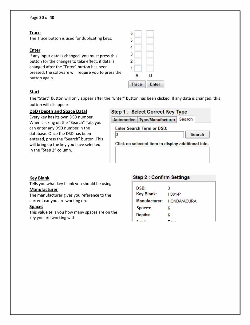
Trace The Trace button is used for duplicating keys. Enter If any input data is changed, you must press this button for the changes to take effect, if data is changed after the “Enter” button has been pressed, the software will require you to press the button again.
Start The “Start” button will only appear after the “Enter” button has been clicked. If any data is changed, this button will disappear. DSD (Depth and Space Data) Every key has its own DSD number. When clicking on the “Search” Tab, you can enter any DSD number in the database. Once the DSD has been entered, press the “Search” button. This will bring up the key you have selected in the “Step 2” column.
Key Blank Tells you what key blank you should be using. Manufacturer The manufacturer gives you reference to the current car you are working on.
Spaces This value tells you how many spaces are on the key you are working with.

Page 31 of 40
Depths This value tells you how many depths are on the key you are working with. Track This tells you how many edges of the key will be cut. There are 3 different types: Four, Two (Left), and Two (Right). Cut This location explains how the key will be cut, internally or externally. Jaw There are 3 types of jaws: Jaw 1, Jaw 2, and Jaw 3. Once the key is chosen, the software will indicate which jaw should be used. Jaw type & Cutter Jaw type & Cutter displays a picture of the jaw type and cutter that should be used to cut the key.
Jaw Clamp This indicates which side of Jaw 2 you should clamp the key with, A, B, C, or D. Stop There are 4 different types of “Stop”: Shoulder, Tip 1, Tip 2, and Tip 3. Make sure that you insert the key to the correct tip stop. If not done properly, you may cut the key wrong or damage the cutter. Comment Boxes There are two comment boxes. The top box displays default comments about the key, while the bottom box displays comments that you set in the edit screen.
The bottom box allows the user to enter notes for a specific key type or comments about the car type. To edit user comments, you go to the “File” menu and click on “Edit”. Once in the “Edit” screen, click on the “Edit” button and a dialog box will appear asking you to verify yourself as an authorized user. Press “Yes” and another box will appear. You do not have to enter a password. In the “Domain” drop-box, press the down arrow key and choose “This Computer”, then press “Submit”. After editing the comments, you MUST click on the “Done” button that has appeared. Failing to do so may cause the software to not recognize the database.

Page 32 of 40
Side A / Side B Spaces The spaces that are needed will show up according to the type of key blank that is being cut. “Side A” will be a left-hand cut to the key, and “Side B” will be a right-hand cut. If “Side A” and “Side B” are present, it will cut both sides of the key. Status This box displays what the 3D Pro is currently working on. It also shows the status of the connection board, whether it has been found by the software or not. The status box will also give you the next step in the process of cutting a key and lets you know when the process of cutting a key is complete.
Re-Connect The re-connect button is only used when the board cannot be found. To use this button you must cycle the power on the machine off and then on again. You may now press the reconnect button to refresh it with the software. The software can only be refreshed once. If it loses the connection after it has already been refreshed you must restart the software. Tech Box This box is located at the bottom right-hand corner of the software interface. If you are having trouble cutting or tracing a key, this box displays data that the service tech will use to fix the problem. This also shows the parameters in which the cutter is going to cut a key and what the tracing parameters were measured at.
Using the Edit Screen The Edit screen is for displaying all of the information about any chosen key. In this screen, the only parameters that can be edited are “Cutting Data” and “Tracing Data”. …. To edit these parameters, follow this procedure: You must have the key chosen that you want to make the changes. If you open the edit screen but notice the wrong key is displayed, simply choose it from the drop down box on the right just like the home screen.

Page 33 of 40
Click on the “Edit” button and a dialog box will appear asking you to verify yourself as an authorized user. Press “Yes” and another box will appear. You do not have to enter a password. In the “Domain” drop down box, choose “This Computer”, now click on “Submit”. After editing the parameters, you MUST click on the “Done” button that has appeared. Failing to do so may corrupt the database in which case you would have to reload it.
Cutting Data This contains the spaces that are on each type of key. Depending on which type of key you are working with, either a shoulder stop or a tip-stop key, this will determine the order of the spacing’s. If you are using a shoulder stop key, the spacing will start from 0 and move up. If using a tip-stop key, it will start with the last cut and move up, in increments, towards the first cut of the key. Depending on the track of the key, there may be “Side A Spaces” and/or “Side B Spaces”.
Cut Depth This is where you enter in how deep the cuts should be. When editing these cuts, you should be careful as not all key depths are calculated the same. (Example: Measuring from the bottom of a Schlage key to the top of the cut would give you the thickness of the key. A 1 depth on a Schlage key should measure .320”) Half Cut Depth This is for use with Determinators. When clicking on the “Half Cut” button on the main screen, it will flash red to indicate that it has been selected. Whatever parameters you have filled in the “Half Cut Depth” boxes, it will use these instead of the default parameters once the button has been selected.

Page 34 of 40
Tracing Data Tracing Data should normally match the “Cutting Data”, but in some cases it will not. End Cuts These are pre-defined parameters of how the tip of each key will be cut, these are not in any way adjustable by the user.
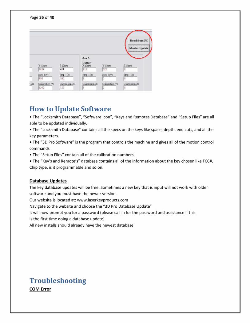
Using the Setup Screen - Read From PC This is the button that you would use to see what the stored calibration numbers are on your computer. Remember that it also stores your preset calibration numbers on the memory in the 3D Pro so you want these numbers to be the same. A lot of times your default calibration numbers that come up once new software is installed are not the correct numbers you want to use, it would be the ones saved in the memory on your 3D Pro.
Example: If you open the software, and the machine is found but the machine does not seem to be acting correctly. Check the setup screen “File/Setup” and it would probably look like Fig. S.1. It is best to first try re-connecting the software to make sure your calibrations are read from the machine.
If you cannot retrieve the preset calibrations stored in your 3D Pro, click on the “Read from PC” button and all of the parameters will be restored to default. You must then click on the “Master Update” button; this will save the calibrations to the memory on the 3D Pro. Keep in mind that these are the “default” calibrations and your machine would need to be recalibrated.
Page 35 of 40
How to Update Software • The “Locksmith Database”, “Software Icon”, “Keys and Remotes Database” and “Setup Files” are all able to be updated individually. • The “Locksmith Database” contains all the specs on the keys like space, depth, end cuts, and all the key parameters. • The “3D Pro Software” is the program that controls the machine and gives all of the motion control commands • The “Setup Files” contain all of the calibration numbers. • The “Key’s and Remote’s” database contains all of the information about the key chosen like FCC#, Chip type, is it programmable and so on. Database Updates The key database updates will be free. Sometimes a new key that is input will not work with older software and you must have the newer version. Our website is located at: www.laserkeyproducts.com Navigate to the website and choose the “3D Pro Database Update” It will now prompt you for a password (please call in for the password and assistance if this is the first time doing a database update) All new installs should already have the newest database
Troubleshooting COM Error

Page 36 of 40
If you start your software and the software says “Communications Error” or “Board Not Found” check these options: 1. Power is going to your 3D Pro from the power outlet. 2. The emergency stop button is disengaged (twisted out according to the arrows) 3. The USB cable from the 3D Pro is plugged into a USB port on your computer. 4. Multiple instances of the 3D Pro software may be running causing a conflict. Open Task Manager by pressing Control Alt Delete on your keyboard and then clicking Task Manager. Look for ‘3D Pro Xtreme.exe’, click it, then click “End Process” Then start the 3D Pro software again.
Humming If when you start the software for the 3D Pro and the machine continuously hums, check that the motor drive cable is plugged into the motor on the left of the main jaw table. You can also try pressing firmly on the red spindle know sticking out the top of the 3D Pro. Freezing Load Bar

Page 37 of 40
If while opening the software the load bar freezes, and the software doesn’t respond, check and make sure that the X motor is plugged in and screwed down. This cable is not connected when the machine is shipped. Also make sure that you are on the latest version of software, some of the earlier versions had issues freezing up on the load bar. If you open your software and it freezes on the blue load bar, check and make sure your version is current. Using an inverter If using an inverter to power the 3D Pro, make sure the inverter is properly grounded to the vehicles chassis otherwise you may incur problems with the operation of the Machine. If a problem occurs that you are unable to repair yourself, please call us at: 281-339-3501

Page 38 of 40
Example of Inverter Chassis Grounding
Changing the Fuses !!Please Disconnect Machine Before Proceeding to Change Fuses!!

Page 39 of 40
Insert a small tipped screwdriver into slotted area in the front face of the fuse box located on the left side of the 3D Pro key machine and pull fuse cartridge toward you.
Once fuse cartridge is open slide out until fuses are fully visible
Install new 6amp 250v fuses into cartridge and push back into fuse box until cartridge snaps into fuse box .