Embed Size (px)
Citation preview
3GPP TS 31.121 V8.3.0 (2009-12) Technical Specification
3rd Generation Partnership Project;Technical Specification Group Core Network and Terminals;
UICC-terminal interface;Universal Subscriber Identity Module (USIM)
application test specification(Release 8)
The present document has been developed within the 3rd Generation Partnership Project (3GPP TM) and may be further elaborated for the purposes of 3GPP. The present document has not been subject to any approval process by the 3GPP Organisational Partners and shall not be implemented. This Specification is provided for future development work within 3GPP only. The Organisational Partners accept no liability for any use of this Specification.Specifications and reports for implementation of the 3GPP TM system should be obtained via the 3GPP Organisational Partners' Publications Offices.
3GPP
Release 8 2 3GPP TS 31.121 V8.3.0 (2009-12)
Keywords UMTS, LTE, SIM, card, testing
3GPP
Postal address
3GPP support office address 650 Route des Lucioles - Sophia Antipolis
Valbonne - FRANCE Tel.: +33 4 92 94 42 00 Fax: +33 4 93 65 47 16
Internet http://www.3gpp.org
Copyright Notification
No part may be reproduced except as authorized by written permission. The copyright and the foregoing restriction extend to reproduction in all media.
© 2009, 3GPP Organizational Partners (ARIB, ATIS, CCSA, ETSI, TTA, TTC).
All rights reserved. UMTS™ is a Trade Mark of ETSI registered for the benefit of its members 3GPP™ is a Trade Mark of ETSI registered for the benefit of its Members and of the 3GPP Organizational Partners LTE™ is a Trade Mark of ETSI currently being registered for the benefit of its Members and of the 3GPP Organizational Partners GSM® and the GSM logo are registered and owned by the GSM Association
3GPP
Release 8 3 3GPP TS 31.121 V8.3.0 (2009-12)
Contents Foreword .................................................................................................................................................... 17 Introduction ................................................................................................................................................ 17 1 Scope ................................................................................................................................................ 18 2 References ........................................................................................................................................ 18 3 Definitions, symbols, abbreviations and coding ................................................................................. 19 3.1 Definitions ................................................................................................................................................. 19 3.2 Symbols ..................................................................................................................................................... 20 3.3 Abbreviations............................................................................................................................................. 20 3.4 Coding Conventions ................................................................................................................................... 22 3.5 Generic procedures for E-UTRAN/UTRAN/GERAN ................................................................................. 22 3.6 Applicability .............................................................................................................................................. 22 3.6.1 Applicability of the present document ................................................................................................... 22 3.6.2 Applicability to terminal equipment ...................................................................................................... 22 3.6.3 Applicability of the individual tests ....................................................................................................... 23 3.7 Table of optional features ........................................................................................................................... 23 3.8 Applicability table .................................................................................................................................... 24 4 Default Values ............................................................................................................................... 32 4.1 Definition of default values for USIM-Terminal interface testing (Default UICC) ....................................... 32 4.1.1 Values of the EF's (Default UICC) ........................................................................................................ 32 4.1.1.1 EFIMSI (IMSI) .................................................................................................................................. 32 4.1.1.2 EFAD (Administrative Data) ............................................................................................................. 32 4.1.1.3 EFLOCI (Location Information) ......................................................................................................... 32 4.1.1.4 EFKeys (Ciphering and Integrity Keys) .............................................................................................. 33 4.1.1.5 EFKeysPS (Ciphering and Integrity Keys for Packet Switched domain)................................................ 33 4.1.1.6 EFACC (Access Control Class) .......................................................................................................... 33 4.1.1.7 EFFPLMN (Forbidden PLMNs) ........................................................................................................... 33 4.1.1.8 EFUST (USIM Service Table) ........................................................................................................... 33 4.1.1.9 EFEST (Enable Service Table) ........................................................................................................... 34 4.1.1.10 EFADN (Abbreviated Dialling Number) ............................................................................................. 34 4.1.1.11 EFPLMNwACT (User Controlled PLMN Selector with Access Technology) .......................................... 34 4.1.1.12 EFOPLMNwACT (Operator Controlled PLMN Selector with Access Technology) .................................. 35 4.1.1.13 Void ................................................................................................................................................ 35 4.1.1.14 PIN ................................................................................................................................................. 35 4.1.1.15 PIN2 ............................................................................................................................................... 35 4.1.1.16 Unblock PIN ................................................................................................................................... 36 4.1.1.17 Unblock PIN2 ................................................................................................................................. 36 4.1.1.18 Other Values of the USIM ............................................................................................................... 36 4.1.1.19 EFPSLOCI (Packet Switch Location Information) ................................................................................ 36 4.1.1.20 Universal PIN ................................................................................................................................. 36 4.1.1.21 Unblock Universal PIN.................................................................................................................... 36 4.2 Definition of FDN UICC ............................................................................................................................ 37 4.2.1 Values of the EF's (FDN UICC) ............................................................................................................ 37 4.2.1.1 EFUST (USIM Service Table) ........................................................................................................... 37 4.2.1.2 EFEST (Enable Service Table) ........................................................................................................... 37 4.2.1.3 EFFDN (Fixed Dialling Numbers) ...................................................................................................... 37 4.2.1.4 EFECC (Emergency Call Codes) ........................................................................................................ 38 4.2.1.5 Other Values of the USIM ............................................................................................................... 38 4.3 Void .......................................................................................................................................................... 38 4.4 Definition of E-UTRAN/EPC UICC ........................................................................................................... 38 4.4.1 EFUST (USIM Service Table) ........................................................................................................... 38 4.4.2 EFEPSLOCI (EPS Information) ............................................................................................................ 39 4.4.3 EFPLMNwACT (User Controlled PLMN Selector with Access Technology) ........................................ 39 4.4.4 EFOPLMNwACT (Operator Controlled PLMN Selector with Access Technology) ................................. 40 4.4.5 EFACSGL (Allowed CSG Lists) ......................................................................................................... 40
3GPP
Release 8 4 3GPP TS 31.121 V8.3.0 (2009-12)
4.4.6 EFCSGT (CSG Type) ......................................................................................................................... 41 4.4.7 EFHNBN (Home (e)NodeB Name) ..................................................................................................... 42 4.4.8 EFEPSNSC (EPS NAS Security Context) ............................................................................................ 44 5 Subscription related tests ................................................................................................................... 44 5.1 IMSI / TMSI handling ................................................................................................................................ 44 5.1.1 UE identification by short IMSI ............................................................................................................ 44 5.1.1.1 Definition and applicability ............................................................................................................. 44 5.1.1.2 Conformance requirement ............................................................................................................... 45 5.1.1.3 Test purpose .................................................................................................................................... 45 5.1.1.4 Method of test ................................................................................................................................. 45 5.1.1.4.1 Initial conditions ........................................................................................................................ 45 5.1.1.4.2 Procedure................................................................................................................................... 45 5.1.1.5 Acceptance criteria .......................................................................................................................... 45 5.1.2 UE identification by short IMSI using a 2 digit MNC ............................................................................ 46 5.1.2.1 Definition and applicability ............................................................................................................. 46 5.1.2.2 Conformance requirement ............................................................................................................... 46 5.1.2.3 Test purpose .................................................................................................................................... 46 5.1.2.4 Method of test ................................................................................................................................. 46 5.1.2.4.1 Initial conditions ........................................................................................................................ 46 5.1.2.4.2 Procedure................................................................................................................................... 47 5.1.2.5 Acceptance criteria .......................................................................................................................... 47 5.1.3 UE identification by "short" TMSI ........................................................................................................ 47 5.1.3.1 Definition and applicability ............................................................................................................. 47 5.1.3.2 Conformance requirement ............................................................................................................... 47 5.1.3.3 Test purpose .................................................................................................................................... 47 5.1.3.4 Method of test ................................................................................................................................. 48 5.1.3.4.1 Initial conditions ........................................................................................................................ 48 5.1.3.4.2 Procedure................................................................................................................................... 48 5.1.3.5 Acceptance criteria .......................................................................................................................... 48 5.1.4 UE identification by "long" TMSI ......................................................................................................... 49 5.1.4.1 Definition and applicability ............................................................................................................. 49 5.1.4.2 Conformance requirement ............................................................................................................... 49 5.1.4.3 Test purpose .................................................................................................................................... 49 5.1.4.4 Method of test ................................................................................................................................. 49 5.1.4.4.1 Initial conditions ........................................................................................................................ 49 5.1.4.4.2 Procedure................................................................................................................................... 50 5.1.4.5 Acceptance criteria .......................................................................................................................... 50 5.1.5 UE identification by long IMSI, TMSI updating and key set identifier assignment ................................. 50 5.1.5.1 Definition and applicability ............................................................................................................. 50 5.1.5.2 Conformance requirement ............................................................................................................... 50 5.1.5.3 Test purpose .................................................................................................................................... 51 5.1.5.4 Method of test ................................................................................................................................. 51 5.1.5.4.1 Initial conditions ........................................................................................................................ 51 5.1.5.4.2 Procedure................................................................................................................................... 52 5.1.5.5 Acceptance criteria .......................................................................................................................... 52 5.1.6 UE identification by short IMSI when accessing E-UTRAN/EPC .......................................................... 53 5.1.6.1 Definition and applicability ............................................................................................................. 53 5.1.6.2 Conformance requirement ............................................................................................................... 53 5.1.6.3 Test purpose .................................................................................................................................... 53 5.1.6.4 Method of test ................................................................................................................................. 54 5.1.6.4.1 Initial conditions ........................................................................................................................ 54 5.1.6.4.2 Procedure................................................................................................................................... 54 5.1.6.5 Acceptance criteria .......................................................................................................................... 54 5.1.7 UE identification by short IMSI using a 2 digit MNC when accessing E-UTRAN/EPC .......................... 54 5.1.7.1 Definition and applicability ............................................................................................................. 54 5.1.7.2 Conformance requirement ............................................................................................................... 54 5.1.7.3 Test purpose .................................................................................................................................... 54 5.1.7.4 Method of test ................................................................................................................................. 55 5.1.7.4.1 Initial conditions ........................................................................................................................ 55 5.1.7.4.2 Procedure................................................................................................................................... 55
3GPP
Release 8 5 3GPP TS 31.121 V8.3.0 (2009-12)
5.1.7.5 Acceptance criteria .......................................................................................................................... 55 5.1.8 UE identification after changed IMSI with service "EMM Information" not available ............................ 55 5.1.8.2 Conformance requirement ............................................................................................................... 56 5.1.8.3 Test purpose .................................................................................................................................... 56 5.1.8.4 Method of test ................................................................................................................................. 56 5.1.8.4.1 Initial conditions ........................................................................................................................ 56 5.1.8.4.2 Procedure................................................................................................................................... 56 5.1.8.5 Acceptance criteria .......................................................................................................................... 57 5.1.9 UE identification by GUTI when using USIM with service "EMM Information" not available ............... 57 5.1.9.2 Conformance requirement ............................................................................................................... 57 5.1.9.3 Test purpose .................................................................................................................................... 57 5.1.9.4 Method of test ................................................................................................................................. 57 5.1.9.4.1 Initial conditions ........................................................................................................................ 57 5.1.9.4.2 Procedure................................................................................................................................... 57 5.1.9.5 Acceptance criteria .......................................................................................................................... 58 5.1.10 UE identification by GUTI when using USIM with service "EMM Information" available ..................... 58 5.1.10.1 Definition and applicability ............................................................................................................. 58 5.1.10.2 Conformance requirement ............................................................................................................... 58 5.1.10.3 Test purpose .................................................................................................................................... 59 5.1.10.4 Method of test ................................................................................................................................. 59 5.1.10.4.1 Initial conditions ........................................................................................................................ 59 5.1.10.4.2 Procedure................................................................................................................................... 59 5.1.10.5 Acceptance criteria .......................................................................................................................... 59 5.2 Access Control handling............................................................................................................................. 59 5.2.1 Access Control information handling .................................................................................................... 59 5.2.1.1 Definition and applicability ............................................................................................................. 59 5.2.1.2 Conformance requirement ............................................................................................................... 60 5.2.1.3 Test purpose .................................................................................................................................... 60 5.2.1.4 Method of test ................................................................................................................................. 60 5.2.1.4.1 Initial conditions ........................................................................................................................ 60 5.2.1.4.2 Coding details .......................................................................................................................... 61 5.2.1.4.3 Procedure................................................................................................................................... 61 5.2.1.5 Acceptance criteria .......................................................................................................................... 62 5.2.2 Access Control information handling for E-UTRAN/EPC ..................................................................... 74 5.2.2.1 Definition and applicability ............................................................................................................. 74 5.2.2.2 Conformance requirement ............................................................................................................... 74 5.2.2.3 Test purpose .................................................................................................................................... 74 5.2.2.4 Method of test ................................................................................................................................. 75 5.2.2.4.1 Initial conditions ........................................................................................................................ 75 5.2.2.4.2 Coding details .......................................................................................................................... 75 5.2.2.4.3 Procedure................................................................................................................................... 75 5.2.2.5 Acceptance criteria .......................................................................................................................... 76 6 Security related Tests ........................................................................................................................ 83 6.1 PIN handling .............................................................................................................................................. 83 6.1.1 Entry of PIN ......................................................................................................................................... 83 6.1.1.1 Definition and applicability ............................................................................................................. 83 Conformance requirement .......................................................................................................................................... 83 6.1.1.3 Test purpose .................................................................................................................................... 83 6.1.1.4 Method of test ................................................................................................................................. 83 6.1.1.4.1 Initial conditions ........................................................................................................................ 83 6.1.1.4.2 Procedure................................................................................................................................... 83 6.1.1.5 Acceptance criteria .......................................................................................................................... 83 6.1.2 Change of PIN ...................................................................................................................................... 83 6.1.2.1 Definition and applicability ............................................................................................................. 83 Conformance requirement .......................................................................................................................................... 84 6.1.2.3 Test purpose .................................................................................................................................... 84 6.1.2.4 Method of test ................................................................................................................................. 84 6.1.2.4.1 Initial conditions ........................................................................................................................ 84 6.1.2.4.2 Procedure................................................................................................................................... 84 6.1.2.5 Acceptance criteria .......................................................................................................................... 84

3GPP
Release 8 6 3GPP TS 31.121 V8.3.0 (2009-12)
6.1.3 Unblock PIN......................................................................................................................................... 84 6.1.3.1 Definition and applicability ............................................................................................................. 84 Conformance requirement .......................................................................................................................................... 84 6.1.3.3 Test purpose .................................................................................................................................... 85 6.1.3.4 Method of test ................................................................................................................................. 85 6.1.3.4.1 Initial conditions ........................................................................................................................ 85 6.1.3.4.2 Procedure................................................................................................................................... 85 6.1.3.5 Acceptance criteria .......................................................................................................................... 85 6.1.4 Entry of PIN2 ....................................................................................................................................... 86 6.1.4.1 Definition and applicability ............................................................................................................. 86 Conformance requirement .......................................................................................................................................... 86 6.1.4.3 Test purpose .................................................................................................................................... 86 6.1.4.4 Method of test ................................................................................................................................. 86 6.1.4.4.1 Initial conditions ........................................................................................................................ 86 6.1.4.4.2 Procedure................................................................................................................................... 86 6.1.4.5 Acceptance criteria .......................................................................................................................... 86 6.1.5 Change of PIN2 .................................................................................................................................... 87 6.1.5.1 Definition and applicability ............................................................................................................. 87 Conformance requirement .......................................................................................................................................... 87 6.1.5.3 Test purpose .................................................................................................................................... 87 6.1.5.4 Method of test ................................................................................................................................. 87 6.1.5.4.1 Initial conditions ........................................................................................................................ 87 6.1.5.4.2 Procedure................................................................................................................................... 87 6.1.5.5 Acceptance criteria .......................................................................................................................... 87 6.1.6 Unblock PIN2 ....................................................................................................................................... 88 6.1.6.1 Definition and applicability ............................................................................................................. 88 Conformance requirement .......................................................................................................................................... 88 6.1.6.3 Test purpose .................................................................................................................................... 88 6.1.6.4 Method of test ................................................................................................................................. 88 6.1.6.4.1 Initial conditions ........................................................................................................................ 88 6.1.6.4.2 Procedure................................................................................................................................... 88 6.1.6.5 Acceptance criterias ........................................................................................................................ 89 6.1.7 Replacement of PIN .............................................................................................................................. 89 6.1.7.1 Definition and applicability ............................................................................................................. 89 Conformance requirement .......................................................................................................................................... 89 6.1.7.3 Test purpose .................................................................................................................................... 89 6.1.7.4 Method of test ................................................................................................................................. 90 6.1.7.4.1 Initial conditions ........................................................................................................................ 90 6.1.7.4.2 Procedure................................................................................................................................... 90 6.1.7.5 Acceptance criteria .......................................................................................................................... 90 6.1.8 Change of Universal PIN ...................................................................................................................... 90 6.1.8.1 Definition and applicability ............................................................................................................. 90 Conformance requirement .......................................................................................................................................... 90 6.1.8.3 Test purpose .................................................................................................................................... 91 6.1.8.4 Method of test ................................................................................................................................. 91 6.1.8.4.1 Initial conditions ........................................................................................................................ 91 6.1.8.4.2 Procedure................................................................................................................................... 91 6.1.8.5 Acceptance criteria .......................................................................................................................... 91 6.1.9 Unblock Universal PIN ......................................................................................................................... 91 6.1.9.1 Definition and applicability ............................................................................................................. 91 Conformance requirement .......................................................................................................................................... 91 6.1.9.3 Test purpose .................................................................................................................................... 91 6.1.9.4 Method of test ................................................................................................................................. 91 6.1.9.4.1 Initial conditions ........................................................................................................................ 91 6.1.9.4.2 Procedure................................................................................................................................... 92 6.1.9.5 Acceptance criteria .......................................................................................................................... 92 6.1.10 Entry of PIN on multi-verification capable UICCs ................................................................................. 92 6.1.10.1 Definition and applicability ............................................................................................................. 92 Conformance requirement .......................................................................................................................................... 92 6.1.10.3 Test purpose .................................................................................................................................... 92
3GPP
Release 8 7 3GPP TS 31.121 V8.3.0 (2009-12)
6.1.10.4 Method of test ................................................................................................................................. 93 6.1.10.4.1 Initial conditions ........................................................................................................................ 93 6.1.10.4.2 Procedure................................................................................................................................... 93 6.1.10.5 Acceptance criteria .......................................................................................................................... 93 6.1.11 Change of PIN on multi-verification capable UICCs.............................................................................. 94 6.1.11.1 Definition and applicability ............................................................................................................. 94 Conformance requirement .......................................................................................................................................... 94 6.1.11.3 Test purpose .................................................................................................................................... 94 6.1.11.4 Method of test ................................................................................................................................. 94 6.1.11.4.1 Initial conditions ........................................................................................................................ 94 6.1.11.4.2 Procedure................................................................................................................................... 95 6.1.11.5 Acceptance criteria .......................................................................................................................... 95 6.1.12 Unblock PIN on multi-verification capable UICCs ................................................................................ 95 6.1.12.1 Definition and applicability ............................................................................................................. 95 6.1.12.2 Conformance requirement .............................................................................................................. 95 6.1.12.3 Test purpose .................................................................................................................................... 95 6.1.12.4 Method of test ................................................................................................................................. 96 6.1.12.4.1 Initial conditions ........................................................................................................................ 96 6.1.12.4.2 Procedure................................................................................................................................... 96 6.1.12.5 Acceptance criteria .......................................................................................................................... 97 6.1.13 Entry of PIN2 on multi-verification capable UICCs ............................................................................... 97 6.1.13.1 Definition and applicability ............................................................................................................. 97 6.1.13.2 Conformance requirement ............................................................................................................... 97 6.1.13.3 Test purpose .................................................................................................................................... 98 6.1.13.4 Method of test ................................................................................................................................. 98 6.1.13.4.1 Initial conditions ........................................................................................................................ 98 6.1.13.4.2 Procedure................................................................................................................................... 99 6.1.13.5 Acceptance criteria .......................................................................................................................... 99 6.1.14 Change of PIN2 on multi-verification capable UICCs ............................................................................ 99 6.1.14.1 Definition and applicability ............................................................................................................. 99 6.1.14.2 Conformance requirement ............................................................................................................... 99 6.1.14.3 Test purpose .................................................................................................................................... 99 6.1.14.4 Method of test ................................................................................................................................. 99 6.1.14.4.1 Initial conditions ........................................................................................................................ 99 6.1.14.4.2 Procedure................................................................................................................................. 100 6.1.14.5 Acceptance criteria ........................................................................................................................ 100 6.1.15 Unblock PIN2 on multi-verification capable UICCs ............................................................................ 101 6.1.15.1 Definition and applicability ........................................................................................................... 101 6.1.15.2 Conformance requirement ............................................................................................................. 101 6.1.15.3 Test purpose .................................................................................................................................. 101 6.1.15.4 Method of test ............................................................................................................................... 101 6.1.15.4.1 Initial conditions ...................................................................................................................... 101 6.1.15.4.2 Procedure................................................................................................................................. 102 6.1.15.5 Acceptance criterias ...................................................................................................................... 102 6.1.16 Replacement of PIN with key reference "07" ....................................................................................... 103 6.1.16.1 Definition and applicability ........................................................................................................... 103 6.1.16.2 Conformance requirement ............................................................................................................. 103 6.1.16.3 Test purpose .................................................................................................................................. 103 6.1.16.4 Method of test ............................................................................................................................... 103 6.1.16.4.1 Initial conditions ...................................................................................................................... 103 6.1.16.4.2 Procedure................................................................................................................................. 104 6.1.16.5 Acceptance criteria ........................................................................................................................ 104 6.2 Fixed Dialling Numbers (FDN) handling .................................................................................................. 105 6.2.1 Terminal and USIM with FDN enabled, EFADN readable and updateable .............................................. 105 6.2.1.1 Definition and applicability ........................................................................................................... 105 6.2.1.2 Conformance requirement ............................................................................................................. 105 6.2.1.3 Test purpose .................................................................................................................................. 105 6.2.1.4 Method of test ............................................................................................................................... 106 6.2.1.4.1 Initial conditions ...................................................................................................................... 106 6.2.1.4.2 Procedure................................................................................................................................. 106
3GPP
Release 8 8 3GPP TS 31.121 V8.3.0 (2009-12)
6.2.1.5 Acceptance criteria ........................................................................................................................ 106 6.2.2 Terminal and USIM with FDN disabled .............................................................................................. 107 6.2.2.1 Definition and applicability ........................................................................................................... 107 6.2.2.2 Conformance requirement ............................................................................................................. 107 6.2.2.3 Test purpose .................................................................................................................................. 107 6.2.2.4 Method of test ............................................................................................................................... 107 6.2.2.4.1 Initial conditions ...................................................................................................................... 107 6.2.2.4.2 Procedure................................................................................................................................. 108 6.2.2.5 Acceptance criteria ........................................................................................................................ 108 6.2.3 Enabling, disabling and updating of FDN ............................................................................................ 108 6.2.3.1 Definition and applicability ........................................................................................................... 108 6.2.3.2 Conformance requirement ............................................................................................................. 108 6.2.3.3 Test purpose .................................................................................................................................. 108 6.2.3.4 Method of test ............................................................................................................................... 108 6.2.3.4.1 Initial conditions ...................................................................................................................... 108 6.2.3.4.2 Procedure................................................................................................................................. 109 6.2.3.5 Acceptance criteria ........................................................................................................................ 109 6.2.4 Terminal and USIM with FDN enabled, EFADN readable and updateable (Rel-4 and onwards) .............. 109 6.2.4.1 Definition and applicability ........................................................................................................... 109 6.2.4.2 Conformance requirement ............................................................................................................. 109 6.2.4.3 Test purpose .................................................................................................................................. 110 6.2.4.4 Method of test ............................................................................................................................... 110 6.2.4.4.1 Initial conditions ...................................................................................................................... 110 6.2.4.4.2 Procedure................................................................................................................................. 110 6.2.4.5 Acceptance criteria ........................................................................................................................ 111 6.3 Void ........................................................................................................................................................ 111 6.4 Advice of charge (AoC) handling ............................................................................................................. 111 6.4.1 AoC not supported by USIM ............................................................................................................... 111 6.4.1.1 Definition and applicability ........................................................................................................... 111 6.4.1.2 Conformance requirement ............................................................................................................. 111 6.4.1.3 Test purpose .................................................................................................................................. 111 6.4.1.4 Method of test ............................................................................................................................... 112 6.4.1.4.1 Initial conditions ...................................................................................................................... 112 6.4.1.4.2 Procedure................................................................................................................................. 112 6.4.1.5 Acceptance criteria ........................................................................................................................ 112 6.4.2 Maximum frequency of ACM updating ............................................................................................... 112 6.4.2.1 Definition and applicability ........................................................................................................... 112 6.4.2.2 Conformance requirement ............................................................................................................. 112 6.4.2.3 Test purpose .................................................................................................................................. 113 6.4.2.4 Method of test ............................................................................................................................... 113 6.4.2.4.1 Initial conditions ...................................................................................................................... 113 6.4.2.4.2 Procedure................................................................................................................................. 114 6.4.2.5 Acceptance criteria ........................................................................................................................ 115 6.4.3 Call terminated when ACM greater than ACMmax ............................................................................. 115 6.4.3.1 Definition and applicability ........................................................................................................... 115 6.4.3.2 Conformance requirement ............................................................................................................. 115 6.4.3.3 Test purpose .................................................................................................................................. 116 6.4.3.4 Method of test ............................................................................................................................... 116 6.4.3.4.1 Initial conditions ...................................................................................................................... 116 6.4.3.4.2 Procedure................................................................................................................................. 117 6.4.3.5 Acceptance criteria ........................................................................................................................ 119 6.4.4 Response codes of increase command of ACM.................................................................................... 119 6.4.4.1 Definition and applicability ........................................................................................................... 119 6.4.4.2 Conformance requirement ............................................................................................................. 119 6.4.4.3 Test purpose .................................................................................................................................. 119 6.4.4.4 Method of test ............................................................................................................................... 120 6.4.4.4.1 Initial conditions ...................................................................................................................... 120 6.4.4.4.2 Procedure................................................................................................................................. 120 6.4.4.5 Acceptance criteria ........................................................................................................................ 122
3GPP
Release 8 9 3GPP TS 31.121 V8.3.0 (2009-12)
7 PLMN related tests ......................................................................................................................... 123 7.1 FPLMN handling ..................................................................................................................................... 123 7.1.1 Adding FPLMN to the Forbidden PLMN list ....................................................................................... 123 7.1.1.1 Definition and applicability ........................................................................................................... 123 7.1.1.2 Conformance requirement ............................................................................................................. 123 7.1.1.3 Test purpose .................................................................................................................................. 125 7.1.1.4 Method of test ............................................................................................................................... 125 7.1.1.4.1 Initial conditions ...................................................................................................................... 125 7.1.1.4.2 Procedure................................................................................................................................. 126 7.1.1.5 Acceptance criteria ........................................................................................................................ 129 7.1.2 UE updating forbidden PLMNs ........................................................................................................... 130 7.1.2.1 Definition and applicability ........................................................................................................... 130 7.1.2.2 Conformance requirement ............................................................................................................. 131 7.1.2.3 Test purpose .................................................................................................................................. 131 7.1.2.4 Method of test ............................................................................................................................... 131 7.1.2.4.1 Initial conditions ...................................................................................................................... 131 7.1.2.4.2 Procedure................................................................................................................................. 132 7.1.2.5 Acceptance criteria ........................................................................................................................ 132 7.1.3 UE deleting forbidden PLMNs ............................................................................................................ 133 7.1.3.1 Definition and applicability ........................................................................................................... 133 7.1.3.2 Conformance requirement ............................................................................................................. 133 7.1.3.3 Test purpose .................................................................................................................................. 134 7.1.3.4 Method of test ............................................................................................................................... 134 7.1.3.4.1 Initial conditions ...................................................................................................................... 134 7.1.3.4.2 Procedure................................................................................................................................. 135 7.1.3.5 Acceptance criteria ........................................................................................................................ 136 7.1.4 Adding FPLMN to the forbidden PLMN list when accessing E-UTRAN ............................................. 137 7.1.4.1 Definition and applicability ........................................................................................................... 137 7.1.4.2 Conformance requirement ............................................................................................................. 137 7.1.4.3 Test purpose .................................................................................................................................. 138 7.1.4.4 Method of test ............................................................................................................................... 138 7.1.4.4.1 Initial conditions ...................................................................................................................... 138 7.1.4.4.2 Procedure................................................................................................................................. 138 7.1.4.5 Acceptance criteria ........................................................................................................................ 139 EFEPSLOCI (EPS Information) ................................................................................................................................. 140 7.1.5 UE updating forbidden PLMNs ........................................................................................................... 140 7.1.5.1 Definition and applicability ........................................................................................................... 140 7.1.5.2 Conformance requirement ............................................................................................................. 140 7.1.5.3 Test purpose .................................................................................................................................. 140 7.1.5.4 Method of test ............................................................................................................................... 140 7.1.5.4.1 Initial conditions ...................................................................................................................... 140 7.1.5.4.2 Procedure................................................................................................................................. 141 7.1.5.5 Acceptance criteria ........................................................................................................................ 141 7.1.6 UE deleting forbidden PLMNs ............................................................................................................ 142 7.1.6.1 Definition and applicability ........................................................................................................... 142 7.1.6.2 Conformance requirement ............................................................................................................. 142 7.1.6.3 Test purpose .................................................................................................................................. 142 7.1.6.4 Method of test ............................................................................................................................... 142 7.1.6.4.1 Initial conditions ...................................................................................................................... 142 7.1.6.4.2 Procedure................................................................................................................................. 143 7.1.6.5 Acceptance criteria ........................................................................................................................ 143 7.2 User controlled PLMN selector handling .................................................................................................. 144 7.2.1 UE updating the User controlled PLMN selector list ............................................................................ 144 7.2.1.1 Definition and applicability ........................................................................................................... 144 7.2.1.2 Conformance requirement ............................................................................................................. 144 7.2.1.3 Test purpose .................................................................................................................................. 144 7.2.1.4 Method of test ............................................................................................................................... 144 7.2.1.4.1 Initial conditions ...................................................................................................................... 144 7.2.1.4.2 Procedure................................................................................................................................. 144 7.2.1.5 Acceptance criteria ........................................................................................................................ 144
3GPP
Release 8 10 3GPP TS 31.121 V8.3.0 (2009-12)
7.2.2 UE recognising the priority order of the User controlled PLMN selector list with the same access technology. ......................................................................................................................................... 145
7.2.2.1 Definition and applicability ........................................................................................................... 145 7.2.2.2 Conformance requirement ............................................................................................................. 145 7.2.2.3 Test purpose .................................................................................................................................. 146 7.2.2.4 Method of test ............................................................................................................................... 146 7.2.2.4.1 Initial conditions ...................................................................................................................... 146 7.2.2.4.2 Procedure................................................................................................................................. 147 7.2.2.5 Acceptance criteria ........................................................................................................................ 148 7.2.3 UE recognising the priority order of the User controlled PLMN selector list using an ACT
preference. .......................................................................................................................................... 149 7.2.3.1 Definition and applicability ........................................................................................................... 149 7.2.3.2 Conformance requirement ............................................................................................................. 149 7.2.3.3 Test purpose ............................................................................................................................ 149 7.2.3.4 Method of test ............................................................................................................................... 149 7.2.3.4.1 Initial conditions ...................................................................................................................... 149 7.2.3.4.2 Procedure................................................................................................................................. 150 7.2.3.5 Acceptance criteria ........................................................................................................................ 150 7.2.4 Void ................................................................................................................................................... 150 7.2.5 UE updating the User controlled PLMN selector list for E-UTRAN ..................................................... 150 7.2.5.1 Definition and applicability ........................................................................................................... 150 7.2.5.2 Conformance requirement ............................................................................................................. 151 7.2.5.3 Test purpose .................................................................................................................................. 151 7.2.5.4 Method of test ............................................................................................................................... 151 7.2.5.4.1 Initial conditions ...................................................................................................................... 151 7.2.5.4.2 Procedure................................................................................................................................. 151 7.2.5.5 Acceptance criteria ........................................................................................................................ 151 7.2.6 UE recognising the priority order of the User controlled PLMN selector list using an ACT
preference- UTRAN/E-UTRAN .......................................................................................................... 152 7.2.6.1 Definition and applicability ........................................................................................................... 152 7.2.6.2 Conformance requirement ............................................................................................................. 152 7.2.6.3 Test purpose ............................................................................................................................ 152 7.2.6.4 Method of test ............................................................................................................................... 152 7.2.6.4.1 Initial conditions ...................................................................................................................... 152 7.2.6.4.2 Procedure................................................................................................................................. 153 7.2.6.5 Acceptance criteria ........................................................................................................................ 153 7.2.7 UE recognising the priority order of the User controlled PLMN selector list using an ACT
preference- GSM/E-UTRAN............................................................................................................... 153 7.2.7.1 Definition and applicability ........................................................................................................... 153 7.2.7.2 Conformance requirement ............................................................................................................. 153 7.2.7.3 Test purpose ............................................................................................................................ 154 7.2.7.4 Method of test ............................................................................................................................... 154 7.2.7.4.1 Initial conditions ...................................................................................................................... 154 7.2.7.4.2 Procedure................................................................................................................................. 154 7.2.7.5 Acceptance criteria ........................................................................................................................ 154 7.3 Operator controlled PLMN selector handling ............................................................................................ 155 7.3.1 UE recognising the priority order of the Operator controlled PLMN selector list. ................................. 155 7.3.1.1 Definition and applicability ........................................................................................................... 155 7.3.1.2 Conformance requirement ............................................................................................................. 155 7.3.1.3 Test purpose .................................................................................................................................. 155 7.3.1.4 Method of test ............................................................................................................................... 155 7.3.1.4.1 Initial conditions ...................................................................................................................... 155 7.3.1.4.2 Procedure................................................................................................................................. 157 7.3.1.5 Acceptance criteria ........................................................................................................................ 158 7.3.2 UE recognising the priority order of the User controlled PLMN selector over the Operator controlled
PLMN selector list. ............................................................................................................................. 159 7.3.2.1 Definition and applicability ........................................................................................................... 159 7.3.2.2 Conformance requirement ............................................................................................................. 159 7.3.2.3 Test purpose .................................................................................................................................. 159 7.3.2.4 Method of test ............................................................................................................................... 159
3GPP
Release 8 11 3GPP TS 31.121 V8.3.0 (2009-12)
7.3.2.4.1 Initial conditions ...................................................................................................................... 159 7.3.2.4.2 Procedure................................................................................................................................. 161 7.3.2.5 Acceptance criteria ........................................................................................................................ 162 7.3.3 UE recognising the priority order of the Operator controlled PLMN selector list when accessing E-
UTRAN .............................................................................................................................................. 163 7.3.3.1 Definition and applicability ........................................................................................................... 163 7.3.3.2 Conformance requirement ............................................................................................................. 163 7.3.3.3 Test purpose .................................................................................................................................. 163 7.3.3.4 Method of test ............................................................................................................................... 163 7.3.3.4.1 Initial conditions ...................................................................................................................... 163 7.3.3.4.2 Procedure................................................................................................................................. 164 7.3.3.5 Acceptance criteria ........................................................................................................................ 164 7.3.4 UE recognising the priority order of the User controlled PLMN selector over the Operator controlled
PLMN selector list – E-UTRAN ......................................................................................................... 165 7.3.4.1 Definition and applicability ........................................................................................................... 165 7.3.4.2 Conformance requirement ............................................................................................................. 165 7.3.4.3 Test purpose .................................................................................................................................. 165 7.3.4.4 Method of test ............................................................................................................................... 165 7.3.4.4.1 Initial conditions ...................................................................................................................... 165 7.3.4.4.2 Procedure................................................................................................................................. 166 7.3.4.5 Acceptance criteria ........................................................................................................................ 166 7.4 Higher priority PLMN search handling ..................................................................................................... 167 7.4.1 UE recognising the search period of the Higher priority PLMN ........................................................... 167 7.4.1.1 Definition and applicability ........................................................................................................... 167 7.4.1.2 Conformance requirement ............................................................................................................. 167 7.4.1.3 Test purpose .................................................................................................................................. 167 7.4.1.4 Method of test ............................................................................................................................... 167 7.4.1.4.1 Initial conditions ...................................................................................................................... 167 7.4.1.4.2 Procedure................................................................................................................................. 168 7.4.1.5 Acceptance criteria ........................................................................................................................ 170 7.4.2 GSM/UMTS dual mode UEs recognising the search period of the Higher priority PLMN .................... 171 7.4.2.1 Definition and applicability ........................................................................................................... 171 7.4.2.2 Conformance requirement ............................................................................................................. 171 7.4.2.3 Test purpose .................................................................................................................................. 172 7.4.2.4 Method of test ............................................................................................................................... 172 7.4.2.4.1 Initial conditions ...................................................................................................................... 172 7.4.2.4.2 Procedure................................................................................................................................. 173 7.4.2.5 Acceptance criteria ........................................................................................................................ 174 7.4.3 UE recognising the search period of the Higher priority PLMN – E-UTRAN ....................................... 175 7.4.3.1 Definition and applicability ........................................................................................................... 175 7.4.3.2 Conformance requirement ............................................................................................................. 175 7.4.3.3 Test purpose .................................................................................................................................. 175 7.4.3.4 Method of test ............................................................................................................................... 175 7.4.3.4.1 Initial conditions ...................................................................................................................... 175 7.4.3.4.2 Procedure................................................................................................................................. 176 7.4.3.5 Acceptance criteria ........................................................................................................................ 176 7.4.4 E-UTRAN/EPC capable UEs recognising the search period of the Higher priority PLMN – GSM/E-
UTRAN .............................................................................................................................................. 177 7.4.4.1 Definition and applicability ........................................................................................................... 177 7.4.4.2 Conformance requirement ............................................................................................................. 177 7.4.4.3 Test purpose .................................................................................................................................. 177 7.4.4.4 Method of test ............................................................................................................................... 177 7.4.4.4.1 Initial conditions ...................................................................................................................... 177 7.4.4.4.2 Procedure................................................................................................................................. 178 7.4.4.5 Acceptance criteria ........................................................................................................................ 179 7.4.5 E-UTRAN/EPC capable UEs recognising the search period of the Higher priority PLMN –
UTRAN/E-UTRAN ............................................................................................................................ 179 7.4.5.1 Definition and applicability ........................................................................................................... 179 7.4.5.2 Conformance requirement ............................................................................................................. 179 7.4.5.3 Test purpose .................................................................................................................................. 179
3GPP
Release 8 12 3GPP TS 31.121 V8.3.0 (2009-12)
7.4.5.4 Method of test ............................................................................................................................... 180 7.4.5.4.1 Initial conditions ...................................................................................................................... 180 7.4.5.4.2 Procedure................................................................................................................................. 181 7.4.5.5 Acceptance criteria ........................................................................................................................ 181 7.5 Void ........................................................................................................................................................ 182 8 Subscription independent tests ........................................................................................................ 182 8.1 Phone book procedures ............................................................................................................................ 182 8.1.1 Recognition of a previously changed phonebook ................................................................................. 182 8.1.1.1 Definition and applicability ........................................................................................................... 182 8.1.1.2 Conformance requirement ............................................................................................................. 182 8.1.1.3 Test purpose .................................................................................................................................. 182 8.1.1.4 Method of test ............................................................................................................................... 182 8.1.1.4.1 Initial conditions ...................................................................................................................... 182 8.1.1.4.2 Procedure................................................................................................................................. 183 8.1.1.5 Acceptance criteria ........................................................................................................................ 183 8.1.2 Update of the Phonebook Synchronisation Counter (PSC) ................................................................... 183 8.1.2.1 Definition and applicability ........................................................................................................... 183 8.1.2.2 Conformance requirement ............................................................................................................. 184 8.1.2.3 Test purpose .................................................................................................................................. 184 8.1.2.4 Method of test ............................................................................................................................... 184 8.1.2.4.1 Initial conditions ...................................................................................................................... 184 8.1.2.4.2 Procedure................................................................................................................................. 184 8.1.2.5 Acceptance criteria ...................................................................................................................... 185 8.1.3 Phonebook content handling ............................................................................................................... 185 8.1.3.1 Handling of BCD number/ SSC content extension.......................................................................... 185 8.1.3.1.1 Definition and applicability ...................................................................................................... 185 Conformance requirement ........................................................................................................................................ 185 8.1.3.1.3 Test purpose ............................................................................................................................ 185 8.1.3.1.4 Method of test .......................................................................................................................... 185 8.1.3.1.5 Acceptance criteria................................................................................................................... 188 8.1.4 Phonebook selection ........................................................................................................................... 189 8.1.4.1 Definition and applicability ........................................................................................................... 189 8.1.4.2 Conformance requirement ............................................................................................................. 189 8.1.4.3 Test purpose .................................................................................................................................. 189 8.1.4.4 Method of test ............................................................................................................................... 189 8.1.4.4.1 Initial conditions ...................................................................................................................... 189 8.1.4.4.2 Procedure................................................................................................................................. 192 8.1.4.5 Acceptance criteria ........................................................................................................................ 193 8.1.5 Local Phonebook handling .................................................................................................................. 193 8.1.5.1 Definition and applicability ........................................................................................................... 193 8.1.5.2 Conformance requirement ............................................................................................................. 194 8.1.5.3 Test purpose .................................................................................................................................. 194 8.1.5.4 Method of test ............................................................................................................................... 194 8.1.5.4.1 Initial conditions ...................................................................................................................... 194 8.1.5.4.2 Procedure................................................................................................................................. 195 8.1.5.5 Acceptance criteria ........................................................................................................................ 195 8.2 Short message handling report .................................................................................................................. 195 8.2.1 Correct storage of a SM on the USIM.................................................................................................. 195 8.2.1.1 Definition and applicability ........................................................................................................... 195 8.2.1.2 Conformance requirement ............................................................................................................. 196 8.2.1.3 Test purpose .................................................................................................................................. 196 8.2.1.4 Method of test ............................................................................................................................... 196 8.2.1.4.1 Initial conditions ...................................................................................................................... 196 8.2.1.4.2 Procedure................................................................................................................................. 198 8.2.1.5 Acceptance criteria ........................................................................................................................ 198 8.2.2 Correct reading of a SM on the USIM ................................................................................................. 200 8.2.2.1 Definition and applicability ........................................................................................................... 200 8.2.2.2 Conformance requirement ............................................................................................................. 200 8.2.2.3 Test purpose .................................................................................................................................. 200 8.2.2.4 Method of test ............................................................................................................................... 200
3GPP
Release 8 13 3GPP TS 31.121 V8.3.0 (2009-12)
8.2.2.4.1 Initial conditions ...................................................................................................................... 200 8.2.2.4.2 Procedure................................................................................................................................. 201 8.2.2.5 Acceptance criteria ........................................................................................................................ 202 8.3 MMS related tests .................................................................................................................................... 202 8.3.1 UE recognising the priority order of MMS Issuer Connectivity Parameters .......................................... 202 8.3.1.1 Definition and applicability ........................................................................................................... 202 8.3.1.2 Conformance requirement ............................................................................................................. 202 8.3.1.3 Test purpose .................................................................................................................................. 202 8.3.1.4 Method of test ............................................................................................................................... 203 8.3.1.4.1 Initial conditions ...................................................................................................................... 203 8.3.1.4.2 Procedure................................................................................................................................. 207 8.3.1.5 Acceptance criteria ........................................................................................................................ 207 8.3.2 UE recognising the priority order of MMS User Connectivity Parameters ............................................ 207 8.3.2.1 Definition and applicability ........................................................................................................... 207 8.3.2.2 Conformance requirement ............................................................................................................. 207 8.3.2.3 Test purpose .................................................................................................................................. 208 8.3.2.4 Method of test ............................................................................................................................... 208 8.3.2.4.1 Initial conditions ...................................................................................................................... 208 8.3.2.4.2 Procedure................................................................................................................................. 213 8.3.2.5 Acceptance criteria ........................................................................................................................ 213 8.3.3 UE recognising the priority order of MMS Issuer Connectivity Parameters over the MMS User
Connectivity Parameters ..................................................................................................................... 213 8.3.3.1 Definition and applicability ........................................................................................................... 213 8.3.3.2 Conformance requirement ............................................................................................................. 214 8.3.3.3 Test purpose .................................................................................................................................. 214 8.3.3.4 Method of test ............................................................................................................................... 214 8.3.3.4.1 Initial conditions ...................................................................................................................... 214 8.3.3.4.2 Procedure................................................................................................................................. 220 8.3.3.5 Acceptance criteria ........................................................................................................................ 220 8.3.4 Usage of MMS notification ................................................................................................................. 220 8.3.4.1 Definition and applicability ........................................................................................................... 220 8.3.4.2 Conformance requirement ............................................................................................................. 220 8.3.4.3 Test purpose .................................................................................................................................. 221 8.3.4.4 Method of test ............................................................................................................................... 221 8.3.4.4.1 Initial conditions ...................................................................................................................... 221 8.3.4.4.2 Procedure................................................................................................................................. 225 8.3.4.5 Acceptance criteria ........................................................................................................................ 225 8.4 UICC presence detection .......................................................................................................................... 226 8.4.1 Definition and applicability ................................................................................................................. 226 8.4.2 Conformance requirement ................................................................................................................... 226 8.4.3 Test purpose ....................................................................................................................................... 226 8.4.4 Method of test..................................................................................................................................... 226 8.4.4.1 Initial conditions............................................................................................................................ 226 8.4.4.2 Procedure ...................................................................................................................................... 227 8.4.5 Acceptance criteria ............................................................................................................................. 227 8.5 UICC presence detection when connected to E-UTRAN/EPC ................................................................... 227 8.5.1 Definition and applicability ................................................................................................................. 227 8.5.2 Conformance requirement ................................................................................................................... 227 8.5.3 Test purpose ....................................................................................................................................... 227 8.5.4 Method of test..................................................................................................................................... 227 8.5.4.1 Initial conditions............................................................................................................................ 227 8.5.4.2 Procedure ...................................................................................................................................... 228 8.5.5 Acceptance criteria ............................................................................................................................. 228 9 USIM service handling ................................................................................................................... 228 9.1 Access Point Name Control List handling ........................................................................................... 228 9.1.1 Access Point Name Control List handling for terminals supporting ACL ............................................. 228 9.1.1.1 Definition and applicability ........................................................................................................... 228 9.1.1.2 Conformance requirement ............................................................................................................. 228 9.1.1.3 Test purpose .................................................................................................................................. 228 9.1.1.4 Method of test ............................................................................................................................... 228
3GPP
Release 8 14 3GPP TS 31.121 V8.3.0 (2009-12)
9.1.1.4.1 Initial conditions ...................................................................................................................... 228 9.1.1.4.2 Procedure................................................................................................................................. 229 9.1.1.5 Acceptance criteria ........................................................................................................................ 229 9.1.2 Network provided APN handling for terminals supporting ACL .......................................................... 230 9.1.2.1 Definition and applicability ........................................................................................................... 230 9.1.2.2 Conformance requirement ............................................................................................................. 230 9.1.2.3 Test purpose .................................................................................................................................. 230 9.1.2.4 Method of test ............................................................................................................................... 230 9.1.2.4.1 Initial conditions ...................................................................................................................... 230 9.1.2.4.2 Procedure................................................................................................................................. 231 9.1.2.5 Acceptance criteria ........................................................................................................................ 231 9.1.3 Access Point Name Control List handling for terminals not supporting ACL........................................ 232 9.1.3.1 Definition and applicability ........................................................................................................... 232 9.1.3.2 Conformance requirement ............................................................................................................. 232 9.1.3.3 Test purpose .................................................................................................................................. 232 9.1.3.4 Method of test ............................................................................................................................... 232 9.1.3.4.1 Initial conditions ...................................................................................................................... 232 9.1.3.4.2 Procedure................................................................................................................................. 233 9.1.3.5 Acceptance criteria ........................................................................................................................ 233 9.1.4 Access Point Name Control List handling for terminals supporting ACL connected to E-
UTRAN/EPC ...................................................................................................................................... 233 9.1.4.1 Definition and applicability ........................................................................................................... 233 9.1.4.2 Conformance requirement ............................................................................................................. 233 9.1.4.3 Test purpose .................................................................................................................................. 233 9.1.4.4 Method of test ............................................................................................................................... 233 9.1.4.4.1 Initial conditions ...................................................................................................................... 233 9.1.4.4.2 Procedure................................................................................................................................. 234 9.1.4.5 Acceptance criteria ........................................................................................................................ 234 9.1.5 Network provided APN handling for terminals supporting ACL connected to E-UTRAN/EPC ............ 235 9.1.5.1 Definition and applicability ........................................................................................................... 235 9.1.5.2 Conformance requirement ............................................................................................................. 235 9.1.5.3 Test purpose .................................................................................................................................. 235 9.1.5.4 Method of test ............................................................................................................................... 235 9.1.5.4.1 Initial conditions ...................................................................................................................... 235 9.1.5.4.2 Procedure................................................................................................................................. 236 9.1.5.5 Acceptance criteria ........................................................................................................................ 236 9.1.6 Access Point Name Control List handling for terminals not supporting ACL connected to E-
UTRAN/EPC ...................................................................................................................................... 237 9.1.6.1 Definition and applicability ........................................................................................................... 237 9.1.6.2 Conformance requirement ............................................................................................................. 237 9.1.6.3 Test purpose .................................................................................................................................. 237 9.1.6.4 Method of test ............................................................................................................................... 237 9.1.6.4.1 Initial conditions ...................................................................................................................... 237 9.1.6.4.2 Procedure................................................................................................................................. 238 9.1.6.5 Acceptance criteria ........................................................................................................................ 238 9.2 Service Dialling Numbers handling .......................................................................................................... 238 9.2.1 Definition and applicability ................................................................................................................. 238 9.2.2 Conformance requirement ................................................................................................................... 238 9.2.3 Test purpose ....................................................................................................................................... 238 9.2.4 Method of test..................................................................................................................................... 239 9.2.4.1 Initial conditions............................................................................................................................ 239 9.2.4.2 Procedure ...................................................................................................................................... 241 9.2.5 Acceptance criteria ............................................................................................................................. 241 10 CSG list handling ............................................................................................................................ 242 10.1 CSG list handling for E-UTRA ................................................................................................................. 242 10.1.1 Automatic CSG selection in E-UTRA with CSG list on USIM, success ............................................... 242 10.1.1.1 Definition and applicability ........................................................................................................... 242 10.1.1.2 Conformance requirement ............................................................................................................. 242 10.1.1.3 Test purpose .................................................................................................................................. 242 10.1.1.4 Method of test ............................................................................................................................... 242
3GPP
Release 8 15 3GPP TS 31.121 V8.3.0 (2009-12)
10.1.1.4.1 Initial conditions ...................................................................................................................... 242 10.1.1.4.2 Procedure................................................................................................................................. 243 10.1.1.5 Acceptance criteria ........................................................................................................................ 243 10.1.2 Automatic CSG selection in E-UTRA with CSG list on USIM, removal of CSG ID from the USIM .... 244 10.1.2.1 Definition and applicability ........................................................................................................... 244 10.1.2.2 Conformance requirement ............................................................................................................. 244 10.1.2.3 Test purpose .................................................................................................................................. 244 10.1.2.4 Method of test ............................................................................................................................... 244 10.1.2.4.1 Initial conditions ...................................................................................................................... 244 10.1.2.4.2 Procedure................................................................................................................................. 245 10.1.2.5 Acceptance criteria ........................................................................................................................ 245 10.1.3 Manual CSG selection in E-UTRA with CSG list on USIM, success .................................................... 246 10.1.3.1 Definition and applicability ........................................................................................................... 246 10.1.3.2 Conformance requirement ............................................................................................................. 246 10.1.3.3 Test purpose .................................................................................................................................. 246 10.1.3.4 Method of test ............................................................................................................................... 246 10.1.3.4.1 Initial conditions ...................................................................................................................... 246 10.1.3.4.2 Procedure................................................................................................................................. 247 10.1.3.5 Acceptance criteria ........................................................................................................................ 247 10.1.4 Manual CSG selection in E-UTRA with CSG list on USIM, rejected ................................................... 249 10.1.4.1 Definition and applicability ........................................................................................................... 249 10.1.4.2 Conformance requirement ............................................................................................................. 249 10.1.4.3 Test purpose .................................................................................................................................. 249 10.1.4.4 Method of test ............................................................................................................................... 249 10.1.4.4.1 Initial conditions ...................................................................................................................... 249 10.1.4.4.2 Procedure................................................................................................................................. 250 10.1.4.5 Acceptance criteria ........................................................................................................................ 250 10.1.5 CSG selection in E-UTRA with no CSG list on USIM, no IMSI change .............................................. 251 10.1.5.1 Definition and applicability ........................................................................................................... 251 10.1.5.2 Conformance requirement ............................................................................................................. 251 10.1.5.3 Test purpose .................................................................................................................................. 251 10.1.5.4 Method of test ............................................................................................................................... 252 10.1.5.4.1 Initial conditions ...................................................................................................................... 252 10.1.5.4.2 Procedure................................................................................................................................. 252 10.1.5.5 Acceptance criteria ........................................................................................................................ 253 10.1.6 CSG selection in E-UTRA with no CSG list on USIM, with IMSI change ........................................... 254 10.1.6.1 Definition and applicability ........................................................................................................... 254 10.1.6.2 Conformance requirement ............................................................................................................. 254 10.1.6.3 Test purpose .................................................................................................................................. 254 10.1.6.4 Method of test ............................................................................................................................... 254 10.1.6.4.1 Initial conditions ...................................................................................................................... 254 10.1.6.4.2 Procedure................................................................................................................................. 255 10.1.6.5 Acceptance criteria ........................................................................................................................ 256 11 NAS security context parameter handling ........................................................................................ 256 11.1 NAS security context parameter handling when service "EMM Information" is available .......................... 256 11.1.1 Definition and applicability ................................................................................................................. 256 11.1.2 Conformance requirement ................................................................................................................... 256 11.1.3 Test purpose ....................................................................................................................................... 257 11.1.4 Method of test..................................................................................................................................... 257 11.1.4.1 Initial conditions............................................................................................................................ 257 11.1.4.2 Procedure ...................................................................................................................................... 257 11.1.5 Acceptance criteria ............................................................................................................................. 258 11.2 NAS security context parameter handling when service "EMM Information" is not available, no IMSI
change ..................................................................................................................................................... 258 11.2.1 Definition and applicability ................................................................................................................. 258 11.2.2 Conformance requirement ................................................................................................................... 258 11.2.3 Test purpose ....................................................................................................................................... 259 11.2.4 Method of test..................................................................................................................................... 259 11.2.4.1 Initial conditions............................................................................................................................ 259 11.2.4.2 Procedure ...................................................................................................................................... 259
3GPP
Release 8 16 3GPP TS 31.121 V8.3.0 (2009-12)
11.2.5 Acceptance criteria ............................................................................................................................. 260 11.3 NAS security context parameter handling when service "EMM Information" is not available, IMSI
changed ................................................................................................................................................... 260 11.3.1 Definition and applicability ................................................................................................................. 260 11.3.2 Conformance requirement ................................................................................................................... 260 11.3.3 Test purpose ....................................................................................................................................... 260 11.3.4 Method of test..................................................................................................................................... 261 11.3.4.1 Initial conditions............................................................................................................................ 261 11.3.4.2 Procedure ...................................................................................................................................... 261 11.3.5 Acceptance criteria ............................................................................................................................. 261
Annex A (informative): Change history ................................................................................................. 263
3GPP
Release 8 17 3GPP TS 31.121 V8.3.0 (2009-12)
Foreword This Technical Specification (TS) has been produced by the 3rd Generation Partnership Project (3GPP).
The contents of the present document are subject to continuing work within the TSG and may change following formal TSG approval. Should the TSG modify the contents of the present document, it will be re-released by the TSG with an identifying change of release date and an increase in version number as follows:
Version x.y.z
where:
x the first digit:
1 presented to TSG for information;
2 presented to TSG for approval;
3 or greater indicates TSG approved document under change control.
Y the second digit is incremented for all changes of substance, i.e. technical enhancements, corrections, updates, etc.
z the third digit is incremented when editorial only changes have been incorporated in the document.
Introduction The present document defines the application test specification.
The aim of the present document is to ensure interoperability between an UICC and a terminal independently of the respective manufacturer, card issuer or operator. The present document does not define any aspects related to the administrative management phase of the UICC. Any internal technical realisation of either the UICC or the Terminal is only specified where these are reflected over the interface.
Application specific details for applications residing on an UICC are specified in the respective application specific documents. The logical and physical Characteristics of the UICC Terminal interface is specified in document ETSI TS 102 221 [5]. The Universal Subscriber Identity Module (USIM)-application for 3G telecommunication networks is specified in document TS 31.102 [4].

3GPP
Release 8 18 3GPP TS 31.121 V8.3.0 (2009-12)
1 Scope The present document provides the UICC –Terminal Interface Conformance Test Specification between a 2G, 3G or 3G E-UTRAN terminal and the USIM (Universal Subscriber Identity Module) as an application on the UICC and the Terminal for a 2G, 3G or 3G E-UTRAN network operation:
- the default setting of the USIM;
- the applicability of each test case;
- the test configurations;
- the conformance requirement and reference to the core specifications;
- the test purposes; and
- a brief description of the test procedure and the specific acceptance criteria.
2 References The following documents contain provisions which, through reference in this text, constitute provisions of the present document.
References are either specific (identified by date of publication, edition number, version number, etc.) or non-specific.
For a specific reference, subsequent revisions do not apply.
For a non-specific reference, the latest version in same release as the implementation release of the terminal under test applies.
[1] Void
[2] Void
[3] 3GPP TS 23.038: "Alphabets and language-specific information".
[4] 3GPP TS 31.102: "Characteristics of the USIM application".
[5] ETSI TS 102 221: "UICC-Terminal interface; Physical and logical characteristics".
[6] 3GPP TS 22.011: "Service accessibility".
[7] 3GPP TR 21.905: "Vocabulary for 3GPP Specifications".
[8] 3GPP TS 22.024: "Description of Charge Advice Information (CAI)".
[9] 3GPP TS 23.086: "Advice of Charge (AoC) Supplementary Service – Stage 2".
[10] 3GPP TS 24.086: "Advice of Charge (AoC) Supplementary Service – Stage 3".
[11] 3GPP TS 22.101: "Service aspects; Service principles".
[12] 3GPP TS 22.030: "Man-Machine Interface (MMI) of the User Equipment (UE)".
[13] 3GPP TS 23.040: "Technical realization of the Short Message Service (SMS)".
[14] 3GPP TS 23.003: "Numbering, Addressing and Identification".
[15] 3GPP TS 44.018: "Mobile radio interface layer 3 specification; Radio Resource Control Protocol".
[16] 3GPP TS 24.008: "Mobile radio interface Layer 3 specification; Core Network protocols; Stage 3".
3GPP
Release 8 19 3GPP TS 31.121 V8.3.0 (2009-12)
[17] 3GPP TS 24.080: "Mobile radio Layer 3 supplementary service specification; Formats and coding".
[18] 3GPP TS 22.086: "Advice of Charge (AoC) supplementary services; Stage 1".
[19] 3GPP TS 21.111: "USIM and IC card requirements".
[20] 3GPP TS 25.331 "Radio Resource Control (RRC); Protocol Specification".
[21] 3GPP TS 34.108 "Common test environments for User Equipment (UE) conformance testing".
[22] 3GPP TS 51.010-1 "Mobile Station (MS) conformance specification; Part1: Conformance specification".
[23] 3GPP TS 23.140 Release 6 "Multimedia Messaging Service (MMS); Functional description; Stage 2".
[24] 3GPP TS 24.002 "GSM – UMTS Public Land Mobile Network (PLMN) Access Reference Configuration".
[25] 3GPP TS 23.060 "General Packet Radio Service (GPRS); Service description; Stage 2".
[26] 3GPP TS 24.301: "Technical Specification Group Core Network and Terminals; Non-Access-Stratum (NAS) protocol for Evolved Packet Systems (EPS): Stage 3".
[27] 3GPP TS 33.401: "3GPP System Architecture Evolution (SAE); Security architecture".
[28] 3GPP TS 36.331: "Evolved Universal Terrestrial Radio Access (E-UTRA) Radio Resource Control (RRC); Protocol specification".
[29] 3GPP TS 36.508: "Evolved Universal Terrestrial Radio Access (E-UTRA) and Evolved Packet Core (EPC); Common test environments for User Equipment (UE) conformance testing"
[30] 3GPP TS 36.523-2 " Evolved Universal Terrestrial Radio Access (E-UTRA) and Evolved Packet Core (EPC);User Equipment (UE) conformance specification;Part 2: Implementation Conformance Statement (ICS) proforma specification"
[31] 3GPP TS 23.122: "Non-Access-Stratum functions related to Mobile Station (MS) in idle mode".
3 Definitions, symbols, abbreviations and coding 3.1 Definitions For the purposes of the present document, the following terms and definitions apply.
Application DF (ADF): entry point to an application
access conditions: set of security attributes associated with a file
access technology: Radio Access Technology of the Terminal (e.g. E-UTRAN, UTRAN or GSM)
application: consists of a set of security mechanisms, files, data and protocols (excluding transmission protocols)
application protocol: set of procedures required by the application
card session: link between the card and the external world starting with the ATR and ending with a subsequent reset or a deactivation of the card
current directory: latest MF or DF or ADF selected
current EF: latest EF selected
data object: information coded as TLV objects, i.e. consisting of a Tag, a Length and a Value part
3GPP
Release 8 20 3GPP TS 31.121 V8.3.0 (2009-12)
Dedicated File (DF): file containing access conditions and, optionally, Elementary Files (Efs) or other Dedicated Files (DFs)
directory: general term for MF, DF and ADF
Elementary File (EF): file containing access conditions and data and no other files
file: directory or an organised set of bytes or records in the UICC
file identifier: 2 bytes which address a file in the UICC
function: function contains a command and a response pair
GSM session: that part of the card session dedicated to the GSM operation
Master File (MF): unique mandatory file containing access conditions and optionally DFs and/or Efs
MMS Relay/Server: MMS-specific network entity/application that is under the control of the MMS service provider
NOTE: An MMS Relay/Server transfers messages, provides operations of the MMS that are specific or required by the mobile environment and provides (temporary and/or persistent) storage services to the MMS
MMS User Agent: application residing on a UE or an external device that performs MMS-specific operations on a user’s behalf
normal USIM operation: relating to general, PIN related, LTE and/or 3G and/or GSM security and subscription related procedures
record: string of bytes within an EF handled as a single entity
record number: number, which identifies a record within an EF
record pointer: pointer, which addresses one record in an EF
terminal: device into which a UICC can be inserted and which is capable of providing access to 3GPP system services to users, either alone or in conjunction with a UICC
User Equipment (UE): terminal with a UICC inserted with one or several Universal Subscriber Identity Module(s) (USIM) available for access either E-UTRANor UTRAN or GERAN or any combination.
USIM session: USIM session is a selectable application session for a USIM application
3.2 Symbols For the purposes of the present document, the following symbols apply:
bx Bit x of byte (leftmost bit is MSB) Bn Byte No. n
3.3 Abbreviations For the purposes of the present document, the following abbreviations apply:
2G 2nd Generation 3G 3rd Generation 3GPP 3rd Generation Partnership Project ACC Access Class ACL APN Control List ACM Accumulated Call Meter ACMmax ACM maximal value ACT Access Technology ADF Application Dedicated File AoC Advice of Charge AoCC Advice of Charge Charging
3GPP
Release 8 21 3GPP TS 31.121 V8.3.0 (2009-12)
APN Access Point Name ASME Access Security Management Entity ATR Answer To Reset BCCH Broadcast Control Channel BCD Binary Coded Decimal BDN Barred Dialling Number CCI Capability / Configuration1 Identifier CCI2 Capability / Configuration(2) Identifier CCM Current Call Meter CK Cipher key CN Core Network CS Circuit switched CSG Closed Subscriber Group DF Dedicated File EPC Evolved Packet Core E-USS Evolved UMTS System Simulator E-UTRA Evolved UTRA EF Elementary File eFDD evolved Frequency Division Duplex EMM EPS Mobility Management EMMI Electrical Man Machine Interface EPS Evolved Packet System eTDD evolved Time Division Duplex Ext n Extension n FDD Frequency Division Duplex FDN Fixed Dialling Number FPLMN Forbidden PLMN GSM Global System for Mobile communications HNB Home NodeB HeNB Home eNodeB HPLMN Home PLMN ICC Integrated Circuit Card ID Identifier IEC International Electrotechnical Commission IK Integrity key IMSI International Mobile Subscriber Identity ISO International Organization for Standardization KSI Key Set Identifier LAC Location Area Code LAI Location Area Information LSB Least Significant Bit MCC Mobile Country Code MF Master File MM Multimedia Message MMI Man Machine Interface MMS Multimedia Messaging Service MNC Mobile Network Code MS Mobile Station MSB Most Significant Bit NAS Non Access Stratum NPI Numbering Plan Identifier OFM Operational Feature Monitor OSI Open System Interconnection P1 Parameter 1 P2 Parameter 2 P3 Parameter 3 PIN Personal Identification Number PLMN Public Land Mobile Network PS Packet switched RACH Random Access Channel

3GPP
Release 8 22 3GPP TS 31.121 V8.3.0 (2009-12)
RFU Reserved for Future Use RRC Radio Resource Control SFI Short File Identifier SM Short Message SMS Short Message Service SS System Simulator (GSM) TDD Time Division Duplex TE Terminal Equipment TLV Tag Length Value TMSI Temporary Mobile Subscriber Identity TON Type Of Number UE User Equipment USIM Universal Subscriber Identity Module USS UMTS System Simulator UTRA Universal Terrestrial Radio Access UTRAN UMTS Terrestrial Radio Access Network VPLMN Visitor PLMN
3.4 Coding Conventions For the purposes of the present document, the following coding conventions apply:
All lengths are presented in bytes, unless otherwise stated. Each byte B is represented by eight bits b8 to b1, where b8 is the most significant bit (MSB) and b1 is the least significant bit (LSB). In each representation, the leftmost bit is the MSB.
In the UICC, all bytes specified as RFU shall be set to '00' and all bits specifies as RFU shall be set to '0'. If the GSM and/or USIM application exists on a UICC or is built on a generic telecommunications card, then other values may apply for the non- GSM or non-USIM applications. The values will be defined in the appropriate specifications for such cards and applications. These bytes and bits shall not be interpreted by a Terminal in a GSM or 3G session.
The coding of all data objects in the present document is according to ETSI TS 102 221 [5]. All data objects are BER-TLV except if otherwise defined.
3.5 Generic procedures for E-UTRAN/UTRAN/GERAN If a test case contains the statement "This test applies to Terminals accessing E-UTRAN", the procedures defined in TS 36.508 [29] shall be the basis for all performed procedures during the test. The procedures in subclause 4.5 describe the default behaviour of a conformant UE regarding the specified protocols to be used for E-UTRAN and the required procedures from the NAS.
If a test case contains the statement "This test applies to Terminals accessing UTRAN", the procedures defined in TS 34.108 [21], subclause 7.2 shall be the basis for all performed procedures during the test. The procedures in subclause 7 describe the default behaviour of a conformant UE regarding the specified protocols to be used for UTRAN and the required procedures from the NAS.
If a test case contains the statement "This test applies to Terminals accessing GERAN", the procedures defined in TS 51.010-1 [22], subclause 10 shall be the basis for all performed procedures during the test. The procedures in subclause 10 describe the default behaviour of a conformant UE regarding the specified protocols to be used for GERAN and the required procedures from the NAS.
3.6 Applicability 3.6.1 Applicability of the present document The present document applies to a terminal equipment supporting the USIM.
3.6.2 Applicability to terminal equipment The applicability to terminal equipment supporting the USIM is specified in table B.1, unless otherwise specified in the specific clause.
3GPP
Release 8 23 3GPP TS 31.121 V8.3.0 (2009-12)
3.6.3 Applicability of the individual tests Table B.1 lists the optional, conditional or mandatory features for which the supplier of the implementation states the support. As pre-condition the supplier of the implementation shall state the support of possible options in table A.1.
The "Release XY ME" columns shows the status of the entries as follows:
The following notations, defined in ISO/IEC 9646-7 [19], are used for the status column:
M mandatory – the capability is required to be supported.
O optional – the capability may be supported or not.
N/A not applicable – in the given context, it is impossible to use the capability.
X prohibited (excluded) – there is a requirement not to use this capability in the given context.
O.i qualified optional – for mutually exclusive or selectable options from a set. "i" is an integer which identifies an unique group of related optional items and the logic of their selection which is defined immediately following the table.
Ci conditional – the requirement on the capability ("M", "O", "X" or "N/A") depends on the support of other optional or conditional items. "i" is an integer identifying an unique conditional status expression which is defined immediately following the table. For nested conditional expressions, the syntax "IF … THEN (IF … THEN … ELSE…) ELSE …" shall be used to avoid ambiguities.
The "Additional test case execution recommendation" column shows the status of the entries as follows:
A applicable - the test is applicable according to the corresponding entry in the "Rxx ME" column
R redundant – the test has to be considered as redundant when the corresponding E-UTRAN/EPC related test of the present document has been validated and successfully executed. In that case the requirement may be verified by means of the E-UTRAN/EPC functionality only.
AERi Additional test case Execution Recommendation – with respect to the above listed definitions of ("A") and ("R") the test is applicable ("A") or redundant ("R") depending on the support of other optional or conditional items. "i" is an integer identifying a unique conditional status expression which is defined immediately following the table. For nested conditional expressions, the syntax "IF ... THEN (IF ... THEN ... ELSE...) ELSE ..." shall be used to avoid ambiguities.
References to items
For each possible item answer (answer in the support column) there exists a unique reference, used, for example, in the conditional expressions. It is defined as the table identifier, followed by a solidus character "/", followed by the item number in the table. If there is more than one support column in a table, the columns shall be discriminated by letters (a, b, etc.), respectively.
EXAMPLE: A.1/4 is the reference to the answer of item 4 in table A.1.
3.7 Table of optional features Support of several features is optional or release dependent for the terminal equipment. However, if an ME states conformance with a specific 3GPP release, it is mandatory for the ME to support all mandatory functions of that release, as stated in table A.1.
The supplier of the implementation shall state the support of possible options in table A.1.
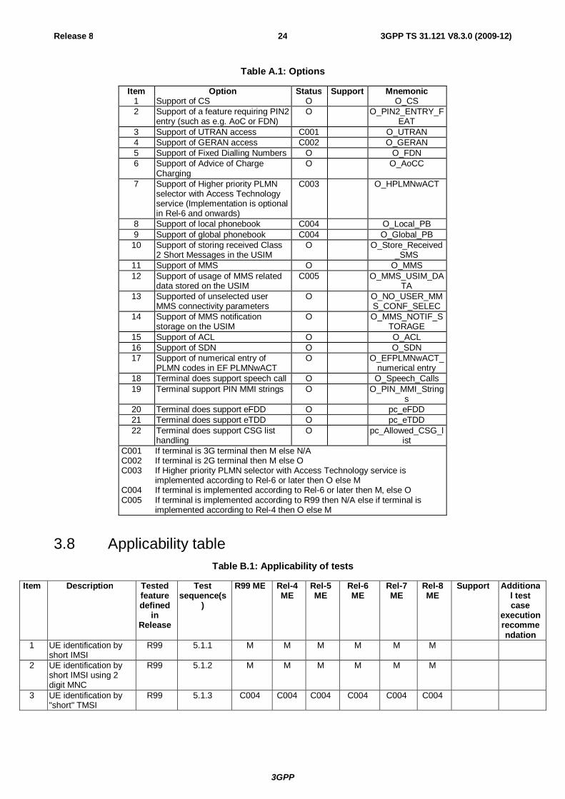
3GPP
Release 8 24 3GPP TS 31.121 V8.3.0 (2009-12)
Table A.1: Options
Item Option Status Support Mnemonic 1 Support of CS O O_CS 2 Support of a feature requiring PIN2
entry (such as e.g. AoC or FDN) O O_PIN2_ENTRY_F
EAT 3 Support of UTRAN access C001 O_UTRAN 4 Support of GERAN access C002 O_GERAN 5 Support of Fixed Dialling Numbers O O_FDN 6 Support of Advice of Charge
Charging O O_AoCC
7 Support of Higher priority PLMN selector with Access Technology service (Implementation is optional in Rel-6 and onwards)
C003 O_HPLMNwACT
8 Support of local phonebook C004 O_Local_PB 9 Support of global phonebook C004 O_Global_PB 10 Support of storing received Class
2 Short Messages in the USIM O O_Store_Received
_SMS 11 Support of MMS O O_MMS 12 Support of usage of MMS related
data stored on the USIM C005 O_MMS_USIM_DA
TA 13 Supported of unselected user
MMS connectivity parameters O O_NO_USER_MM
S_CONF_SELEC 14 Support of MMS notification
storage on the USIM O O_MMS_NOTIF_S
TORAGE 15 Support of ACL O O_ACL 16 Support of SDN O O_SDN 17 Support of numerical entry of
PLMN codes in EF PLMNwACT O O_EFPLMNwACT_
numerical entry 18 Terminal does support speech call O O_Speech_Calls 19 Terminal support PIN MMI strings O O_PIN_MMI_String
s 20 Terminal does support eFDD O pc_eFDD 21 Terminal does support eTDD O pc_eTDD 22 Terminal does support CSG list
handling O pc_Allowed_CSG_l
ist C001 If terminal is 3G terminal then M else N/A C002 If terminal is 2G terminal then M else O C003 If Higher priority PLMN selector with Access Technology service is
implemented according to Rel-6 or later then O else M C004 If terminal is implemented according to Rel-6 or later then M, else O C005 If terminal is implemented according to R99 then N/A else if terminal is
implemented according to Rel-4 then O else M
3.8 Applicability table Table B.1: Applicability of tests
Item Description Tested feature defined
in Release
Test sequence(s
)
R99 ME Rel-4 ME
Rel-5 ME
Rel-6 ME
Rel-7 ME
Rel-8 ME
Support Additional test case
execution recommendation
1 UE identification by short IMSI
R99 5.1.1 M M M M M M
2 UE identification by short IMSI using 2 digit MNC
R99 5.1.2 M M M M M M
3 UE identification by "short" TMSI
R99 5.1.3 C004 C004 C004 C004 C004 C004
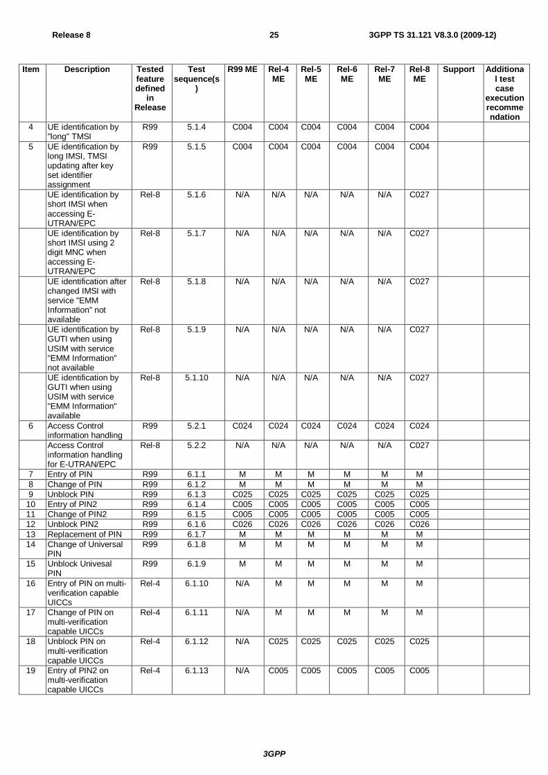
3GPP
Release 8 25 3GPP TS 31.121 V8.3.0 (2009-12)
Item Description Tested feature defined
in Release
Test sequence(s
)
R99 ME Rel-4 ME
Rel-5 ME
Rel-6 ME
Rel-7 ME
Rel-8 ME
Support Additional test case
execution recommendation
4 UE identification by "long" TMSI
R99 5.1.4 C004 C004 C004 C004 C004 C004
5 UE identification by long IMSI, TMSI updating after key set identifier assignment
R99 5.1.5 C004 C004 C004 C004 C004 C004
UE identification by short IMSI when accessing E-UTRAN/EPC
Rel-8 5.1.6 N/A N/A N/A N/A N/A C027
UE identification by short IMSI using 2 digit MNC when accessing E-UTRAN/EPC
Rel-8 5.1.7 N/A N/A N/A N/A N/A C027
UE identification after changed IMSI with service "EMM Information" not available
Rel-8 5.1.8 N/A N/A N/A N/A N/A C027
UE identification by GUTI when using USIM with service "EMM Information" not available
Rel-8 5.1.9 N/A N/A N/A N/A N/A C027
UE identification by GUTI when using USIM with service "EMM Information" available
Rel-8 5.1.10 N/A N/A N/A N/A N/A C027
6 Access Control information handling
R99 5.2.1 C024 C024 C024 C024 C024 C024
Access Control information handling for E-UTRAN/EPC
Rel-8 5.2.2 N/A N/A N/A N/A N/A C027
7 Entry of PIN R99 6.1.1 M M M M M M 8 Change of PIN R99 6.1.2 M M M M M M 9 Unblock PIN R99 6.1.3 C025 C025 C025 C025 C025 C025
10 Entry of PIN2 R99 6.1.4 C005 C005 C005 C005 C005 C005 11 Change of PIN2 R99 6.1.5 C005 C005 C005 C005 C005 C005 12 Unblock PIN2 R99 6.1.6 C026 C026 C026 C026 C026 C026 13 Replacement of PIN R99 6.1.7 M M M M M M 14 Change of Universal
PIN R99 6.1.8 M M M M M M
15 Unblock Univesal PIN
R99 6.1.9 M M M M M M
16 Entry of PIN on multi-verification capable UICCs
Rel-4 6.1.10 N/A M M M M M
17 Change of PIN on multi-verification capable UICCs
Rel-4 6.1.11 N/A M M M M M
18 Unblock PIN on multi-verification capable UICCs
Rel-4 6.1.12 N/A C025 C025 C025 C025 C025
19 Entry of PIN2 on multi-verification capable UICCs
Rel-4 6.1.13 N/A C005 C005 C005 C005 C005
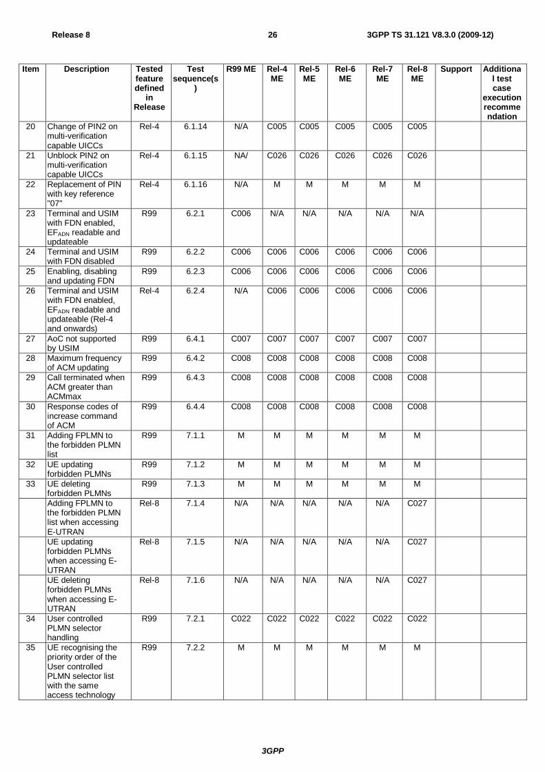
3GPP
Release 8 26 3GPP TS 31.121 V8.3.0 (2009-12)
Item Description Tested feature defined
in Release
Test sequence(s
)
R99 ME Rel-4 ME
Rel-5 ME
Rel-6 ME
Rel-7 ME
Rel-8 ME
Support Additional test case
execution recommendation
20 Change of PIN2 on multi-verification capable UICCs
Rel-4 6.1.14 N/A C005 C005 C005 C005 C005
21 Unblock PIN2 on multi-verification capable UICCs
Rel-4 6.1.15 NA/ C026 C026 C026 C026 C026
22 Replacement of PIN with key reference "07"
Rel-4 6.1.16 N/A M M M M M
23 Terminal and USIM with FDN enabled, EFADN readable and updateable
R99 6.2.1 C006 N/A N/A N/A N/A N/A
24 Terminal and USIM with FDN disabled
R99 6.2.2 C006 C006 C006 C006 C006 C006
25 Enabling, disabling and updating FDN
R99 6.2.3 C006 C006 C006 C006 C006 C006
26 Terminal and USIM with FDN enabled, EFADN readable and updateable (Rel-4 and onwards)
Rel-4 6.2.4 N/A C006 C006 C006 C006 C006
27 AoC not supported by USIM
R99 6.4.1 C007 C007 C007 C007 C007 C007
28 Maximum frequency of ACM updating
R99 6.4.2 C008 C008 C008 C008 C008 C008
29 Call terminated when ACM greater than ACMmax
R99 6.4.3 C008 C008 C008 C008 C008 C008
30 Response codes of increase command of ACM
R99 6.4.4 C008 C008 C008 C008 C008 C008
31 Adding FPLMN to the forbidden PLMN list
R99 7.1.1 M M M M M M
32 UE updating forbidden PLMNs
R99 7.1.2 M M M M M M
33 UE deleting forbidden PLMNs
R99 7.1.3 M M M M M M
Adding FPLMN to the forbidden PLMN list when accessing E-UTRAN
Rel-8 7.1.4 N/A N/A N/A N/A N/A C027
UE updating forbidden PLMNs when accessing E-UTRAN
Rel-8 7.1.5 N/A N/A N/A N/A N/A C027
UE deleting forbidden PLMNs when accessing E-UTRAN
Rel-8 7.1.6 N/A N/A N/A N/A N/A C027
34 User controlled PLMN selector handling
R99 7.2.1 C022 C022 C022 C022 C022 C022
35 UE recognising the priority order of the User controlled PLMN selector list with the same access technology
R99 7.2.2 M M M M M M
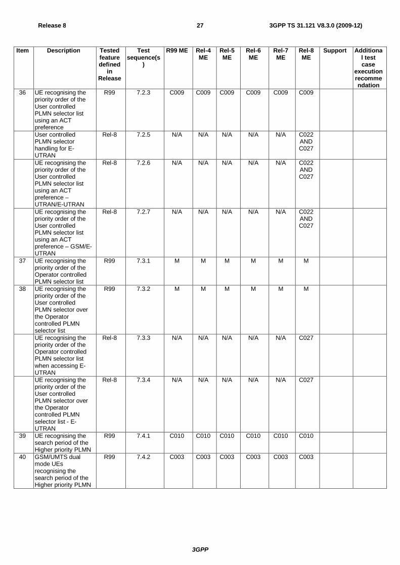
3GPP
Release 8 27 3GPP TS 31.121 V8.3.0 (2009-12)
Item Description Tested feature defined
in Release
Test sequence(s
)
R99 ME Rel-4 ME
Rel-5 ME
Rel-6 ME
Rel-7 ME
Rel-8 ME
Support Additional test case
execution recommendation
36 UE recognising the priority order of the User controlled PLMN selector list using an ACT preference
R99 7.2.3 C009 C009 C009 C009 C009 C009
User controlled PLMN selector handling for E-UTRAN
Rel-8 7.2.5 N/A N/A N/A N/A N/A C022 AND C027
UE recognising the priority order of the User controlled PLMN selector list using an ACT preference – UTRAN/E-UTRAN
Rel-8 7.2.6 N/A N/A N/A N/A N/A C022 AND C027
UE recognising the priority order of the User controlled PLMN selector list using an ACT preference – GSM/E-UTRAN
Rel-8 7.2.7 N/A N/A N/A N/A N/A C022 AND C027
37 UE recognising the priority order of the Operator controlled PLMN selector list
R99 7.3.1 M M M M M M
38 UE recognising the priority order of the User controlled PLMN selector over the Operator controlled PLMN selector list
R99 7.3.2 M M M M M M
UE recognising the priority order of the Operator controlled PLMN selector list when accessing E-UTRAN
Rel-8 7.3.3 N/A N/A N/A N/A N/A C027
UE recognising the priority order of the User controlled PLMN selector over the Operator controlled PLMN selector list - E-UTRAN
Rel-8 7.3.4 N/A N/A N/A N/A N/A C027
39 UE recognising the search period of the Higher priority PLMN
R99 7.4.1 C010 C010 C010 C010 C010 C010
40 GSM/UMTS dual mode UEs recognising the search period of the Higher priority PLMN
R99 7.4.2 C003 C003 C003 C003 C003 C003
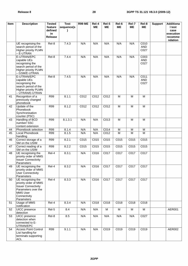
3GPP
Release 8 28 3GPP TS 31.121 V8.3.0 (2009-12)
Item Description Tested feature defined
in Release
Test sequence(s
)
R99 ME Rel-4 ME
Rel-5 ME
Rel-6 ME
Rel-7 ME
Rel-8 ME
Support Additional test case
execution recommendation
UE recognising the search period of the Higher priority PLMN – E-UTRAN
Rel-8 7.4.3 N/A N/A N/A N/A N/A C010 AND C027
E-UTRAN/EPC capable UEs recognising the search period of the Higher priority PLMN – GSM/E-UTRAN
Rel-8 7.4.4 N/A N/A N/A N/A N/A C003 AND C027
E-UTRAN/EPC capable UEs recognising the search period of the Higher priority PLMN – UTRAN/E-UTRAN
Rel-8 7.4.5 N/A N/A N/A N/A N/A C011 AND C027
41 Recognition of a previously changed phonebook
R99 8.1.1 C012 C012 C012 M M M
42 Update of the Phonebook Synchronisation counter (PSC)
R99 8.1.2 C012 C012 C012 M M M
43 Handling of BCD number/ SSC content extension
R99 8.1.3.1 N/A N/A C013 M M M
44 Phonebook selection R99 8.1.4 N/A N/A C014 M M M 45 Local Phonebook
handling R99 8.1.5 N/A N/A C012 M M M
46 Correct storage of a SM on the USIM
R99 8.2.1 C015 C015 C015 C015 C015 C015
47 Correct reading of a SM on the USIM
R99 8.2.2 C015 C015 C015 C015 C015 C015
48 UE recognising the priority order of MMS Issuer Connectivity Parameters
Rel-4 8.3.1 N/A C016 C017 C017 C017 C017
49 UE recognising the priority order of MMS User Connectivity Parameters
Rel-4 8.3.2 N/A C016 C017 C017 C017 C017
50 UE recognising the priority order of MMS Issuer Connectivity Parameters over the MMS User Connectivity Parameters
Rel-4 8.3.3 N/A C016 C017 C017 C017 C017
51 Usage of MMS notification
Rel-4 8.3.4 N/A C018 C018 C018 C018 C018
52 UICC presence detection
Rel-5 8.4 N/A N/A M M M M AER001
53 UICC presence detection when connected to E-UTRAN/EPC
Rel-8 8.5 N/A N/A N/A N/A N/A C027
54 Access Point Control List handling for terminals supporting ACL
R99 9.1.1 N/A N/A C019 C019 C019 C019 AER002
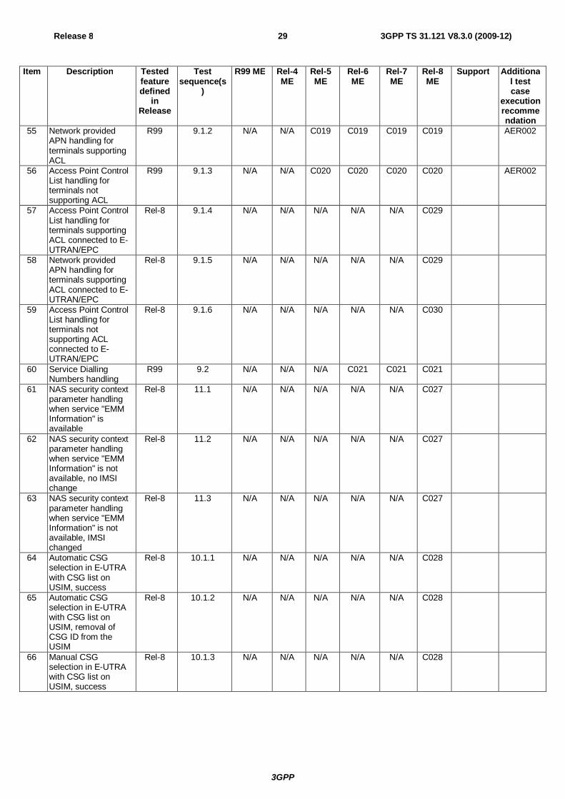
3GPP
Release 8 29 3GPP TS 31.121 V8.3.0 (2009-12)
Item Description Tested feature defined
in Release
Test sequence(s
)
R99 ME Rel-4 ME
Rel-5 ME
Rel-6 ME
Rel-7 ME
Rel-8 ME
Support Additional test case
execution recommendation
55 Network provided APN handling for terminals supporting ACL
R99 9.1.2 N/A N/A C019 C019 C019 C019 AER002
56 Access Point Control List handling for terminals not supporting ACL
R99 9.1.3 N/A N/A C020 C020 C020 C020 AER002
57 Access Point Control List handling for terminals supporting ACL connected to E-UTRAN/EPC
Rel-8 9.1.4 N/A N/A N/A N/A N/A C029
58 Network provided APN handling for terminals supporting ACL connected to E-UTRAN/EPC
Rel-8 9.1.5 N/A N/A N/A N/A N/A C029
59 Access Point Control List handling for terminals not supporting ACL connected to E-UTRAN/EPC
Rel-8 9.1.6 N/A N/A N/A N/A N/A C030
60 Service Dialling Numbers handling
R99 9.2 N/A N/A N/A C021 C021 C021
61 NAS security context parameter handling when service "EMM Information" is available
Rel-8 11.1 N/A N/A N/A N/A N/A C027
62 NAS security context parameter handling when service "EMM Information" is not available, no IMSI change
Rel-8 11.2 N/A N/A N/A N/A N/A C027
63 NAS security context parameter handling when service "EMM Information" is not available, IMSI changed
Rel-8 11.3 N/A N/A N/A N/A N/A C027
64 Automatic CSG selection in E-UTRA with CSG list on USIM, success
Rel-8 10.1.1 N/A N/A N/A N/A N/A C028
65 Automatic CSG selection in E-UTRA with CSG list on USIM, removal of CSG ID from the USIM
Rel-8 10.1.2 N/A N/A N/A N/A N/A C028
66 Manual CSG selection in E-UTRA with CSG list on USIM, success
Rel-8 10.1.3 N/A N/A N/A N/A N/A C028
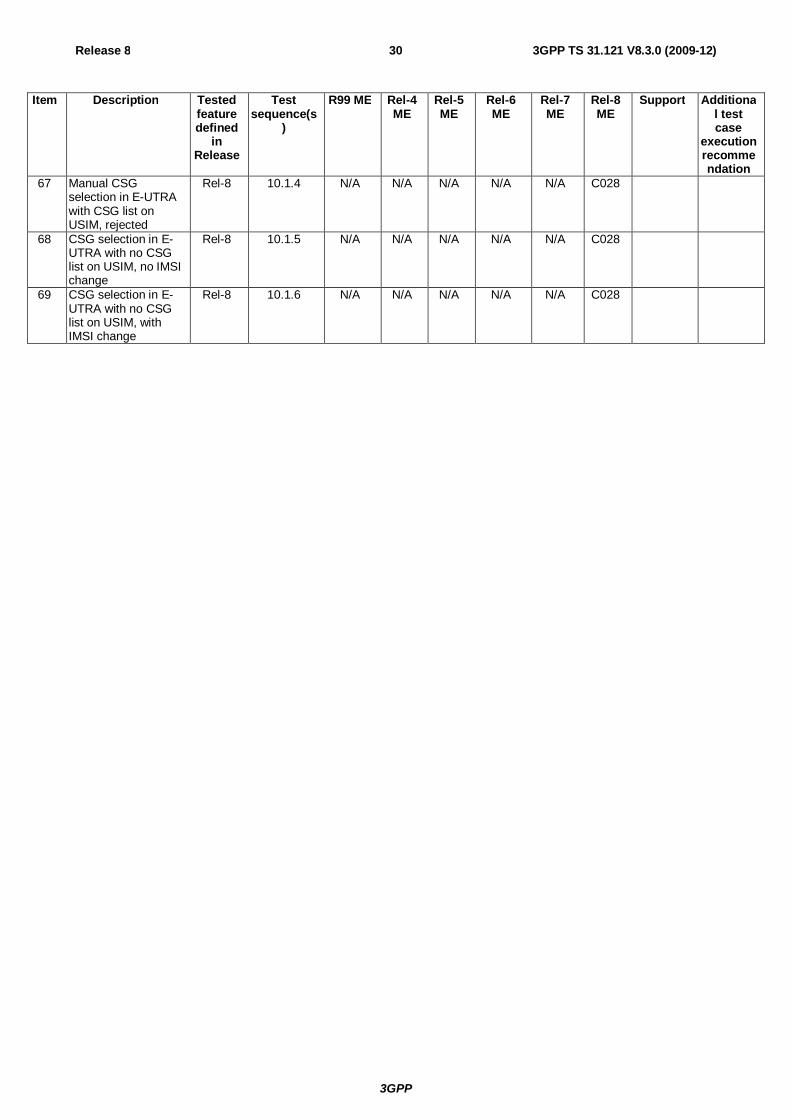
3GPP
Release 8 30 3GPP TS 31.121 V8.3.0 (2009-12)
Item Description Tested feature defined
in Release
Test sequence(s
)
R99 ME Rel-4 ME
Rel-5 ME
Rel-6 ME
Rel-7 ME
Rel-8 ME
Support Additional test case
execution recommendation
67 Manual CSG selection in E-UTRA with CSG list on USIM, rejected
Rel-8 10.1.4 N/A N/A N/A N/A N/A C028
68 CSG selection in E-UTRA with no CSG list on USIM, no IMSI change
Rel-8 10.1.5 N/A N/A N/A N/A N/A C028
69 CSG selection in E-UTRA with no CSG list on USIM, with IMSI change
Rel-8 10.1.6 N/A N/A N/A N/A N/A C028
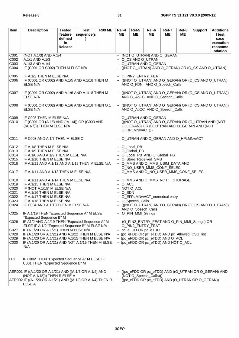
3GPP
Release 8 31 3GPP TS 31.121 V8.3.0 (2009-12)
Item Description Tested feature defined
in Release
Test sequence(s
)
R99 ME Rel-4 ME
Rel-5 ME
Rel-6 ME
Rel-7 ME
Rel-8 ME
Support Additional test case
execution recommendation
C001 (NOT A.1/3) AND A.1/4 C002 A.1/1 AND A.1/3 C003 A.1/3 AND A.1/4 C004 IF (C001 OR C002) THEN M ELSE N/A C005 IF A.1/2 THEN M ELSE N/A C006 IF (C001 OR C002) AND A.1/5 AND A.1/18 THEN M
ELSE N/A C007 IF (C001 OR C002) AND A.1/6 AND A.1/18 THEN M
ELSE N/A C008 IF (C001 OR C002) AND A.1/6 AND A.1/18 THEN O.1
ELSE N/A C009 IF C003 THEN M ELSE N/A C010 IF (C001 OR (A.1/3 AND (!A.1/4)) OR (C003 AND
(!A.1/7))) THEN M ELSE N/A C011 IF C003 AND A.1/7 THEN M ELSE O C012 IF A.1/8 THEN M ELSE N/A C013 IF A.1/9 THEN M ELSE N/A C014 IF A.1/8 AND A.1/9 THEN M ELSE N/A C015 IF A.1/10 THEN M ELSE N/A C016 IF A.1/11 AND A.1/12 AND A.1/13 THEN M ELSE N/A C017 IF A.1/11 AND A.1/13 THEN M ELSE N/A C018 IF A.1/11 AND A.1/14 THEN M ELSE N/A C019 IF A.1/15 THEN M ELSE N/A C020 IF (NOT A.1/15) M ELSE N/A C021 IF A.1/16 THEN M ELSE N/A C022 IF A.1/17 THEN M ELSE N/A C023 IF A.1/18 THEN M ELSE N/A C024 IF C004 AND A.1/18 THEN M ELSE N/A C025 IF A.1/19 THEN “Expected Sequence A” M ELSE
“Expected Sequence B” M C026 IF A1/2 AND A.1/19 THEN “Expected Sequence A” M
ELSE IF A.1/2 “Expected Sequence B” M ELSE N/A C027 IF (A.1/20 OR A.1/21) THEN M ELSE N/A C028 IF (A.1/20 OR A.1/21) AND A.1/22 THEN M ELSE N/A C029 IF (A.1/20 OR A.1/21) AND A.1/15 THEN M ELSE N/A C030 IF (A.1/20 OR A.1/21) AND NOT A.1/15 THEN M ELSE
N/A O.1 IF C002 THEN "Expected Sequence A" M ELSE IF
C001 THEN "Expected Sequence B" M AER001 IF ((A.1/20 OR A.1/21) AND ((A.1/3 OR A.1/4) AND
(NOT A.1/18))) THEN R ELSE A AER002 IF ((A.1/20 OR A.1/21) AND ((A.1/3 OR A.1/4) THEN R
ELSE A
-- (NOT O_UTRAN) AND O_GERAN -- O_CS AND O_UTRAN -- O_UTRAN AND O_GERAN -- ((NOT O_UTRAN) AND O_GERAN) OR (O_CS AND O_UTRAN) -- O_PIN2_ENTRY_FEAT -- (((NOT O_UTRAN) AND O_GERAN) OR (O_CS AND O_UTRAN)
AND O_FDN AND O_Speech_Calls -- (((NOT O_UTRAN) AND O_GERAN) OR (O_CS AND O_UTRAN))
AND O_AoCC AND O_Speech_Calls -- (((NOT O_UTRAN) AND O_GERAN) OR (O_CS AND O_UTRAN))
AND O_AoCC AND O_Speech_Calls -- O_UTRAN AND O_GERAN -- (((NOT O_UTRAN) AND O_GERAN) OR (O_UTRAN AND (NOT
O_GERAN)) OR (O_UTRAN AND O_GERAN AND (NOT O_HPLMNwACT)))
-- O_UTRAN AND O_GERAN AND O_HPLMNwACT -- O_Local_PB -- O_Global_PB -- O_Local_PB AND O_Global_PB -- O_Store_Received_SMS -- O_MMS AND O_MMS_USIM_DATA AND
O_NO_USER_MMS_CONF_SELEC -- O_MMS AND O_NO_USER_MMS_CONF_SELEC -- O_MMS AND O_MMS_NOTIF_STORAGE -- O_ACL -- NOT O_ACL -- O_SDN -- O_EFPLMNwACT_numerical entry -- O_Speech_Calls -- (((NOT O_UTRAN) AND O_GERAN) OR (O_CS AND O_UTRAN))
AND O_Speech_Calls -- O_PIN_MMI_Strings -- (O_PIN2_ENTRY_FEAT AND O_PIN_MMI_Strings) OR
O_PIN2_ENTRY_FEAT -- pc_eFDD OR pc_eTDD -- (pc_eFDD OR pc_eTDD) AND pc_Allowed_CSG_list -- (pc_eFDD OR pc_eTDD) AND O_ACL -- (pc_eFDD OR pc_eTDD) AND NOT O_ACL -- ((pc_eFDD OR pc_eTDD) AND ((O_UTRAN OR O_GERAN) AND
(NOT O_Speech_Calls))) -- ((pc_eFDD OR pc_eTDD) AND (O_UTRAN OR O_GERAN))
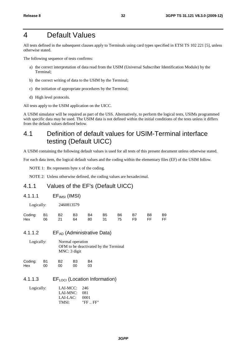
3GPP
Release 8 32 3GPP TS 31.121 V8.3.0 (2009-12)
4 Default Values All tests defined in the subsequent clauses apply to Terminals using card types specified in ETSI TS 102 221 [5], unless otherwise stated.
The following sequence of tests confirms:
a) the correct interpretation of data read from the USIM (Universal Subscriber Identification Module) by the Terminal;
b) the correct writing of data to the USIM by the Terminal;
c) the initiation of appropriate procedures by the Terminal;
d) High level protocols.
All tests apply to the USIM application on the UICC.
A USIM simulator will be required as part of the USS. Alternatively, to perform the logical tests, USIMs programmed with specific data may be used. The USIM data is not defined within the initial conditions of the tests unless it differs from the default values defined below.
4.1 Definition of default values for USIM-Terminal interface testing (Default UICC)
A USIM containing the following default values is used for all tests of this present document unless otherwise stated.
For each data item, the logical default values and the coding within the elementary files (EF) of the USIM follow.
NOTE 1: Bx represents byte x of the coding.
NOTE 2: Unless otherwise defined, the coding values are hexadecimal.
4.1.1 Values of the EF's (Default UICC)
4.1.1.1 EFIMSI (IMSI)
Logically: 2460813579
Coding: B1 B2 B3 B4 B5 B6 B7 B8 B9 Hex 06 21 64 80 31 75 F9 FF FF
4.1.1.2 EFAD (Administrative Data)
Logically: Normal operation OFM to be deactivated by the Terminal MNC: 3 digit
Coding: B1 B2 B3 B4 Hex 00 00 00 03
4.1.1.3 EFLOCI (Location Information)
Logically: LAI-MCC: 246 LAI-MNC: 081 LAI-LAC: 0001 TMSI: "FF .. FF"
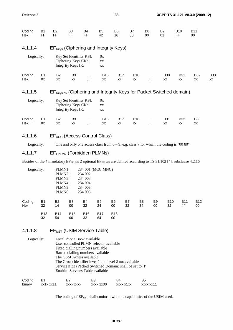
3GPP
Release 8 33 3GPP TS 31.121 V8.3.0 (2009-12)
Coding: B1 B2 B3 B4 B5 B6 B7 B8 B9 B10 B11 Hex FF FF FF FF 42 16 80 00 01 FF 00
4.1.1.4 EFKeys (Ciphering and Integrity Keys)
Logically: Key Set Identifier KSI: 0x Ciphering Keys CK: xx Integrity Keys IK: xx
Coding: B1 B2 B3 … B16 B17 B18 … B30 B31 B32 B33 Hex 0x xx xx … xx xx xx … xx xx xx xx
4.1.1.5 EFKeysPS (Ciphering and Integrity Keys for Packet Switched domain)
Logically: Key Set Identifier KSI: 0x Ciphering Keys CK: xx Integrity Keys IK: xx
Coding: B1 B2 B3 … B16 B17 B18 … B31 B32 B33 Hex 0x xx xx … xx xx xx … xx xx xx
4.1.1.6 EFACC (Access Control Class)
Logically: One and only one access class from 0 – 9, e.g. class 7 for which the coding is "00 80".
4.1.1.7 EFFPLMN (Forbidden PLMNs)
Besides of the 4 mandatory EFFPLMN 2 optional EFFPLMN are defined according to TS 31.102 [4], subclause 4.2.16.
Logically: PLMN1: 234 001 (MCC MNC) PLMN2: 234 002 PLMN3: 234 003 PLMN4: 234 004 PLMN5: 234 005 PLMN6: 234 006
Coding: B1 B2 B3 B4 B5 B6 B7 B8 B9 B10 B11 B12 Hex 32 14 00 32 24 00 32 34 00 32 44 00 B13 B14 B15 B16 B17 B18 32 54 00 32 64 00
4.1.1.8 EFUST (USIM Service Table)
Logically: Local Phone Book available User controlled PLMN selector available Fixed dialling numbers available Barred dialling numbers available The GSM Access available The Group Identifier level 1 and level 2 not available Service n 33 (Packed Switched Domain) shall be set to '1'
Enabled Services Table available
Coding: B1 B2 B3 B4 B5 binary xx1x xx11 xxxx xxxx xxxx 1x00 xxxx x1xx xxxx xx11
The coding of EFUST shall conform with the capabilities of the USIM used.
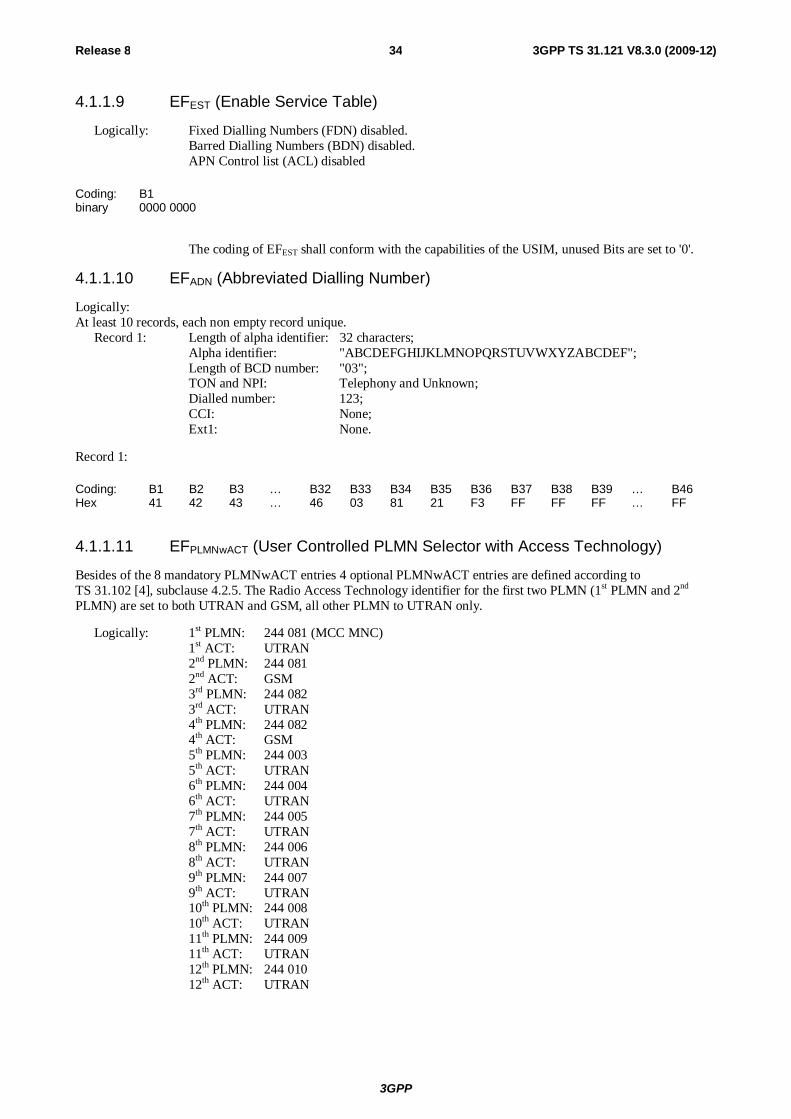
3GPP
Release 8 34 3GPP TS 31.121 V8.3.0 (2009-12)
4.1.1.9 EFEST (Enable Service Table)
Logically: Fixed Dialling Numbers (FDN) disabled. Barred Dialling Numbers (BDN) disabled. APN Control list (ACL) disabled
Coding: B1 binary 0000 0000
The coding of EFEST shall conform with the capabilities of the USIM, unused Bits are set to '0'.
4.1.1.10 EFADN (Abbreviated Dialling Number)
Logically: At least 10 records, each non empty record unique.
Record 1: Length of alpha identifier: 32 characters; Alpha identifier: "ABCDEFGHIJKLMNOPQRSTUVWXYZABCDEF"; Length of BCD number: "03"; TON and NPI: Telephony and Unknown; Dialled number: 123; CCI: None; Ext1: None.
Record 1:
Coding: B1 B2 B3 … B32 B33 B34 B35 B36 B37 B38 B39 … B46 Hex 41 42 43 … 46 03 81 21 F3 FF FF FF … FF
4.1.1.11 EFPLMNwACT (User Controlled PLMN Selector with Access Technology)
Besides of the 8 mandatory PLMNwACT entries 4 optional PLMNwACT entries are defined according to TS 31.102 [4], subclause 4.2.5. The Radio Access Technology identifier for the first two PLMN (1st PLMN and 2nd PLMN) are set to both UTRAN and GSM, all other PLMN to UTRAN only.
Logically: 1st PLMN: 244 081 (MCC MNC) 1st ACT: UTRAN 2nd PLMN: 244 081 2nd ACT: GSM 3rd PLMN: 244 082 3rd ACT: UTRAN 4th PLMN: 244 082 4th ACT: GSM 5th PLMN: 244 003 5th ACT: UTRAN 6th PLMN: 244 004 6th ACT: UTRAN 7th PLMN: 244 005 7th ACT: UTRAN 8th PLMN: 244 006 8th ACT: UTRAN 9th PLMN: 244 007 9th ACT: UTRAN 10th PLMN: 244 008 10th ACT: UTRAN 11th PLMN: 244 009 11th ACT: UTRAN 12th PLMN: 244 010 12th ACT: UTRAN
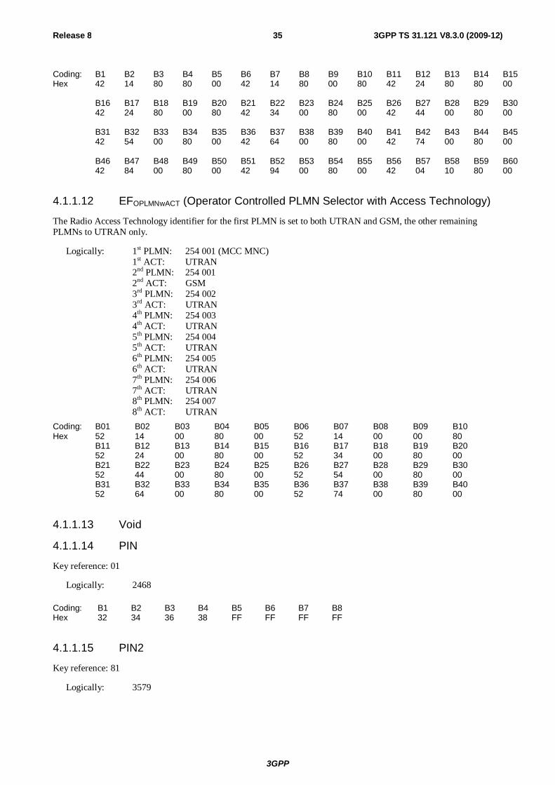
3GPP
Release 8 35 3GPP TS 31.121 V8.3.0 (2009-12)
Coding: B1 B2 B3 B4 B5 B6 B7 B8 B9 B10 B11 B12 B13 B14 B15 Hex 42 14 80 80 00 42 14 80 00 80 42 24 80 80 00 B16 B17 B18 B19 B20 B21 B22 B23 B24 B25 B26 B27 B28 B29 B30 42 24 80 00 80 42 34 00 80 00 42 44 00 80 00 B31 B32 B33 B34 B35 B36 B37 B38 B39 B40 B41 B42 B43 B44 B45 42 54 00 80 00 42 64 00 80 00 42 74 00 80 00 B46 B47 B48 B49 B50 B51 B52 B53 B54 B55 B56 B57 B58 B59 B60 42 84 00 80 00 42 94 00 80 00 42 04 10 80 00
4.1.1.12 EFOPLMNwACT (Operator Controlled PLMN Selector with Access Technology)
The Radio Access Technology identifier for the first PLMN is set to both UTRAN and GSM, the other remaining PLMNs to UTRAN only.
Logically: 1st PLMN: 254 001 (MCC MNC) 1st ACT: UTRAN 2nd PLMN: 254 001 2nd ACT: GSM 3rd PLMN: 254 002 3rd ACT: UTRAN 4th PLMN: 254 003 4th ACT: UTRAN 5th PLMN: 254 004 5th ACT: UTRAN 6th PLMN: 254 005 6th ACT: UTRAN 7th PLMN: 254 006 7th ACT: UTRAN 8th PLMN: 254 007 8th ACT: UTRAN
Coding: B01 B02 B03 B04 B05 B06 B07 B08 B09 B10 Hex 52 14 00 80 00 52 14 00 00 80 B11 B12 B13 B14 B15 B16 B17 B18 B19 B20 52 24 00 80 00 52 34 00 80 00 B21 B22 B23 B24 B25 B26 B27 B28 B29 B30 52 44 00 80 00 52 54 00 80 00 B31 B32 B33 B34 B35 B36 B37 B38 B39 B40 52 64 00 80 00 52 74 00 80 00
4.1.1.13 Void
4.1.1.14 PIN
Key reference: 01
Logically: 2468
Coding: B1 B2 B3 B4 B5 B6 B7 B8 Hex 32 34 36 38 FF FF FF FF
4.1.1.15 PIN2
Key reference: 81
Logically: 3579
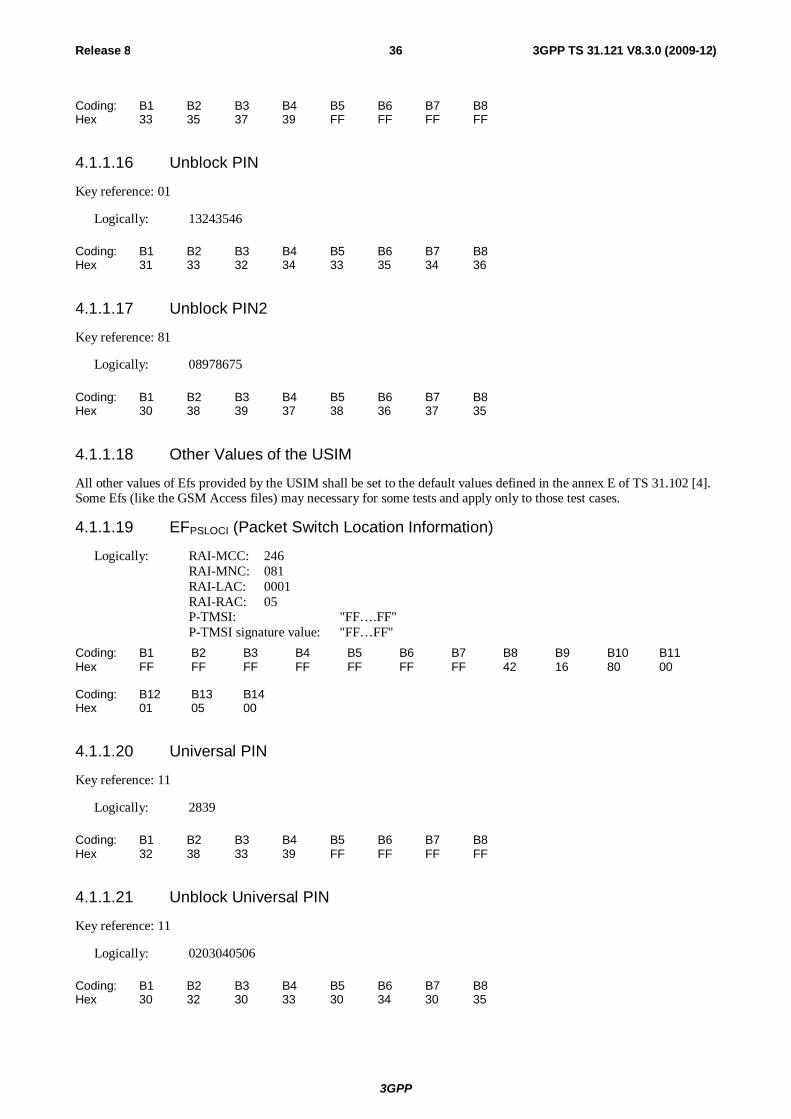
3GPP
Release 8 36 3GPP TS 31.121 V8.3.0 (2009-12)
Coding: B1 B2 B3 B4 B5 B6 B7 B8 Hex 33 35 37 39 FF FF FF FF
4.1.1.16 Unblock PIN
Key reference: 01
Logically: 13243546
Coding: B1 B2 B3 B4 B5 B6 B7 B8 Hex 31 33 32 34 33 35 34 36
4.1.1.17 Unblock PIN2
Key reference: 81
Logically: 08978675
Coding: B1 B2 B3 B4 B5 B6 B7 B8 Hex 30 38 39 37 38 36 37 35
4.1.1.18 Other Values of the USIM
All other values of Efs provided by the USIM shall be set to the default values defined in the annex E of TS 31.102 [4]. Some Efs (like the GSM Access files) may necessary for some tests and apply only to those test cases.
4.1.1.19 EFPSLOCI (Packet Switch Location Information)
Logically: RAI-MCC: 246 RAI-MNC: 081 RAI-LAC: 0001 RAI-RAC: 05 P-TMSI: "FF….FF" P-TMSI signature value: "FF…FF"
Coding: B1 B2 B3 B4 B5 B6 B7 B8 B9 B10 B11 Hex FF FF FF FF FF FF FF 42 16 80 00 Coding: B12 B13 B14 Hex 01 05 00
4.1.1.20 Universal PIN
Key reference: 11
Logically: 2839
Coding: B1 B2 B3 B4 B5 B6 B7 B8 Hex 32 38 33 39 FF FF FF FF
4.1.1.21 Unblock Universal PIN
Key reference: 11
Logically: 0203040506
Coding: B1 B2 B3 B4 B5 B6 B7 B8 Hex 30 32 30 33 30 34 30 35
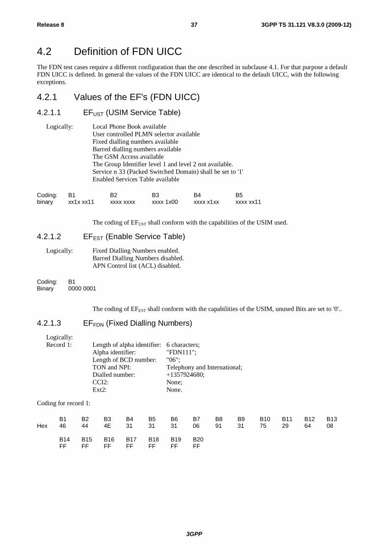
3GPP
Release 8 37 3GPP TS 31.121 V8.3.0 (2009-12)
4.2 Definition of FDN UICC The FDN test cases require a different configuration than the one described in subclause 4.1. For that purpose a default FDN UICC is defined. In general the values of the FDN UICC are identical to the default UICC, with the following exceptions.
4.2.1 Values of the EF's (FDN UICC) 4.2.1.1 EFUST (USIM Service Table)
Logically: Local Phone Book available User controlled PLMN selector available Fixed dialling numbers available Barred dialling numbers available The GSM Access available The Group Identifier level 1 and level 2 not available. Service n 33 (Packed Switched Domain) shall be set to '1'
Enabled Services Table available
Coding: B1 B2 B3 B4 B5 binary xx1x xx11 xxxx xxxx xxxx 1x00 xxxx x1xx xxxx xx11
The coding of EFUST shall conform with the capabilities of the USIM used.
4.2.1.2 EFEST (Enable Service Table)
Logically: Fixed Dialling Numbers enabled. Barred Dialling Numbers disabled. APN Control list (ACL) disabled.
Coding: B1 Binary 0000 0001
The coding of EFEST shall conform with the capabilities of the USIM, unused Bits are set to '0'..
4.2.1.3 EFFDN (Fixed Dialling Numbers)
Logically: Record 1: Length of alpha identifier: 6 characters; Alpha identifier: "FDN111"; Length of BCD number: "06"; TON and NPI: Telephony and International; Dialled number: +1357924680; CCI2: None; Ext2: None.
Coding for record 1:
B1 B2 B3 B4 B5 B6 B7 B8 B9 B10 B11 B12 B13 Hex 46 44 4E 31 31 31 06 91 31 75 29 64 08 B14 B15 B16 B17 B18 B19 B20 FF FF FF FF FF FF FF
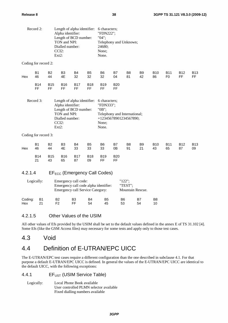
3GPP
Release 8 38 3GPP TS 31.121 V8.3.0 (2009-12)
Record 2: Length of alpha identifier: 6 characters; Alpha identifier: "FDN222"; Length of BCD number: "04"; TON and NPI: Telephony and Unknown; Dialled number: 24680; CCI2: None; Ext2: None.
Coding for record 2:
B1 B2 B3 B4 B5 B6 B7 B8 B9 B10 B11 B12 B13 Hex 46 44 4E 32 32 32 04 81 42 86 F0 FF FF B14 B15 B16 B17 B18 B19 B20 FF FF FF FF FF FF FF
Record 3: Length of alpha identifier: 6 characters; Alpha identifier: "FDN333"; Length of BCD number: "0B"; TON and NPI: Telephony and International; Dialled number: +12345678901234567890; CCI2: None; Ext2: None.
Coding for record 3:
B1 B2 B3 B4 B5 B6 B7 B8 B9 B10 B11 B12 B13 Hex 46 44 4E 33 33 33 0B 91 21 43 65 87 09 B14 B15 B16 B17 B18 B19 B20 21 43 65 87 09 FF FF
4.2.1.4 EFECC (Emergency Call Codes)
Logically: Emergency call code: "122"; Emergency call code alpha identifier: "TEST"; Emergency call Service Category: Mountain Rescue.
Coding: B1 B2 B3 B4 B5 B6 B7 B8 Hex 21 F2 FF 54 45 53 54 10
4.2.1.5 Other Values of the USIM
All other values of Efs provided by the USIM shall be set to the default values defined in the annex E of TS 31.102 [4]. Some Efs (like the GSM Access files) may necessary for some tests and apply only to those test cases.
4.3 Void
4.4 Definition of E-UTRAN/EPC UICC The E-UTRAN/EPC test cases require a different configuration than the one described in subclause 4.1. For that purpose a default E-UTRAN/EPC UICC is defined. In general the values of the E-UTRAN/EPC UICC are identical to the default UICC, with the following exceptions:
4.4.1 EFUST (USIM Service Table)
Logically: Local Phone Book available User controlled PLMN selector available Fixed dialling numbers available
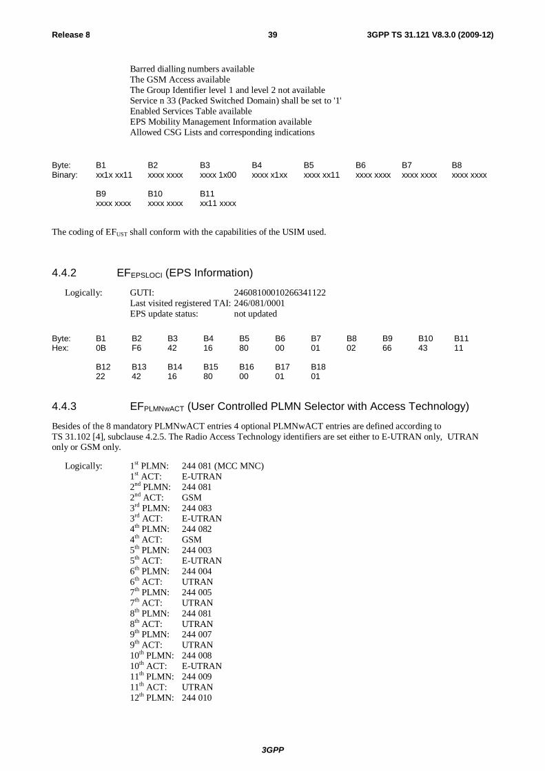
3GPP
Release 8 39 3GPP TS 31.121 V8.3.0 (2009-12)
Barred dialling numbers available The GSM Access available The Group Identifier level 1 and level 2 not available Service n 33 (Packed Switched Domain) shall be set to '1'
Enabled Services Table available EPS Mobility Management Information available Allowed CSG Lists and corresponding indications
Byte: B1 B2 B3 B4 B5 B6 B7 B8 Binary: xx1x xx11 xxxx xxxx xxxx 1x00 xxxx x1xx xxxx xx11 xxxx xxxx xxxx xxxx xxxx xxxx B9 B10 B11 xxxx xxxx xxxx xxxx xx11 xxxx
The coding of EFUST shall conform with the capabilities of the USIM used.
4.4.2 EFEPSLOCI (EPS Information)
Logically: GUTI: 24608100010266341122 Last visited registered TAI: 246/081/0001 EPS update status: not updated
Byte: B1 B2 B3 B4 B5 B6 B7 B8 B9 B10 B11 Hex: 0B F6 42 16 80 00 01 02 66 43 11 B12 B13 B14 B15 B16 B17 B18 22 42 16 80 00 01 01
4.4.3 EFPLMNwACT (User Controlled PLMN Selector with Access Technology)
Besides of the 8 mandatory PLMNwACT entries 4 optional PLMNwACT entries are defined according to TS 31.102 [4], subclause 4.2.5. The Radio Access Technology identifiers are set either to E-UTRAN only, UTRAN only or GSM only.
Logically: 1st PLMN: 244 081 (MCC MNC) 1st ACT: E-UTRAN 2nd PLMN: 244 081 2nd ACT: GSM 3rd PLMN: 244 083 3rd ACT: E-UTRAN 4th PLMN: 244 082 4th ACT: GSM 5th PLMN: 244 003 5th ACT: E-UTRAN 6th PLMN: 244 004 6th ACT: UTRAN 7th PLMN: 244 005 7th ACT: UTRAN 8th PLMN: 244 081 8th ACT: UTRAN 9th PLMN: 244 007 9th ACT: UTRAN 10th PLMN: 244 008 10th ACT: E-UTRAN 11th PLMN: 244 009 11th ACT: UTRAN 12th PLMN: 244 010
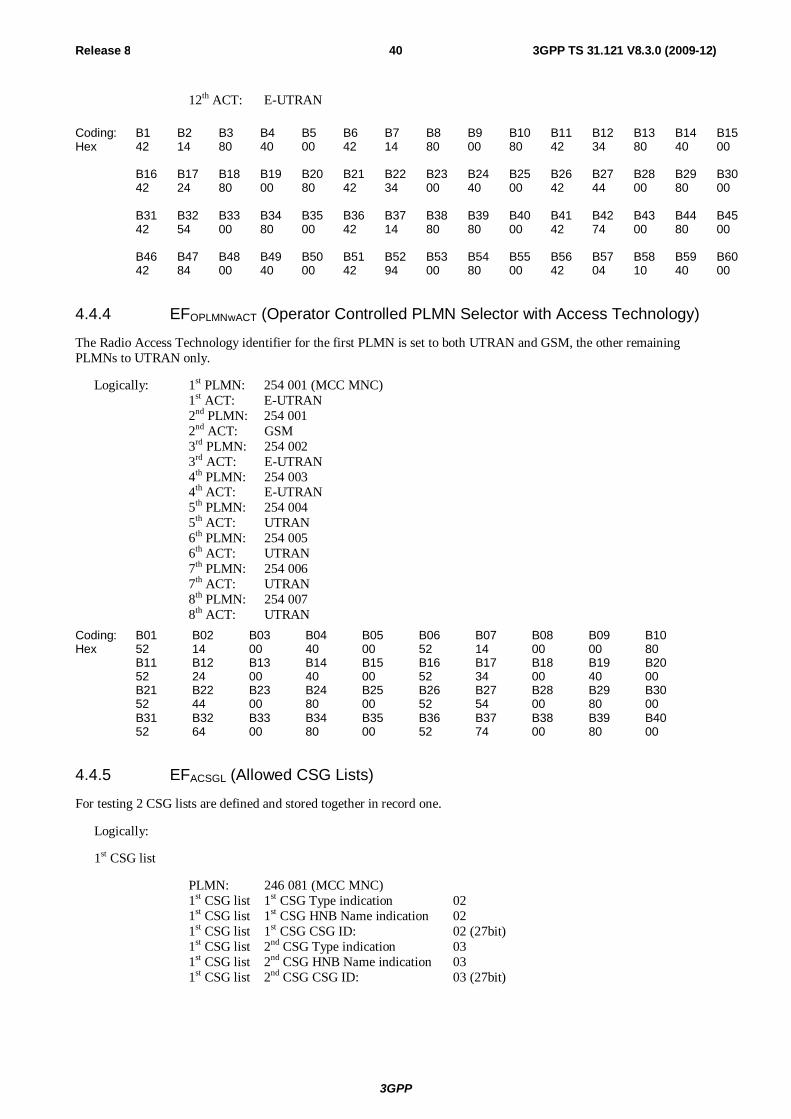
3GPP
Release 8 40 3GPP TS 31.121 V8.3.0 (2009-12)
12th ACT: E-UTRAN
Coding: B1 B2 B3 B4 B5 B6 B7 B8 B9 B10 B11 B12 B13 B14 B15 Hex 42 14 80 40 00 42 14 80 00 80 42 34 80 40 00 B16 B17 B18 B19 B20 B21 B22 B23 B24 B25 B26 B27 B28 B29 B30 42 24 80 00 80 42 34 00 40 00 42 44 00 80 00 B31 B32 B33 B34 B35 B36 B37 B38 B39 B40 B41 B42 B43 B44 B45 42 54 00 80 00 42 14 80 80 00 42 74 00 80 00 B46 B47 B48 B49 B50 B51 B52 B53 B54 B55 B56 B57 B58 B59 B60 42 84 00 40 00 42 94 00 80 00 42 04 10 40 00
4.4.4 EFOPLMNwACT (Operator Controlled PLMN Selector with Access Technology)
The Radio Access Technology identifier for the first PLMN is set to both UTRAN and GSM, the other remaining PLMNs to UTRAN only.
Logically: 1st PLMN: 254 001 (MCC MNC) 1st ACT: E-UTRAN 2nd PLMN: 254 001 2nd ACT: GSM 3rd PLMN: 254 002 3rd ACT: E-UTRAN 4th PLMN: 254 003 4th ACT: E-UTRAN 5th PLMN: 254 004 5th ACT: UTRAN 6th PLMN: 254 005 6th ACT: UTRAN 7th PLMN: 254 006 7th ACT: UTRAN 8th PLMN: 254 007 8th ACT: UTRAN
Coding: B01 B02 B03 B04 B05 B06 B07 B08 B09 B10 Hex 52 14 00 40 00 52 14 00 00 80 B11 B12 B13 B14 B15 B16 B17 B18 B19 B20 52 24 00 40 00 52 34 00 40 00 B21 B22 B23 B24 B25 B26 B27 B28 B29 B30 52 44 00 80 00 52 54 00 80 00 B31 B32 B33 B34 B35 B36 B37 B38 B39 B40 52 64 00 80 00 52 74 00 80 00
4.4.5 EFACSGL (Allowed CSG Lists)
For testing 2 CSG lists are defined and stored together in record one.
Logically:
1st CSG list
PLMN: 246 081 (MCC MNC) 1st CSG list 1st CSG Type indication 02 1st CSG list 1st CSG HNB Name indication 02 1st CSG list 1st CSG CSG ID: 02 (27bit) 1st CSG list 2nd CSG Type indication 03 1st CSG list 2nd CSG HNB Name indication 03 1st CSG list 2nd CSG CSG ID: 03 (27bit)
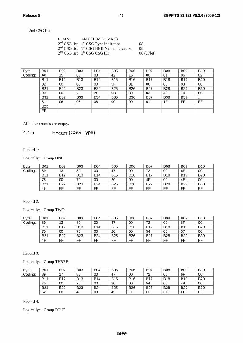
3GPP
Release 8 41 3GPP TS 31.121 V8.3.0 (2009-12)
2nd CSG list
PLMN: 244 081 (MCC MNC) 2nd CSG list 1st CSG Type indication 08 2nd CSG list 1st CSG HNB Name indication 08 2nd CSG list 1st CSG CSG ID: 08 (27bit)
Byte: B01 B02 B03 B04 B05 B06 B07 B08 B09 B10 Coding: A0 15 80 03 42 16 80 81 06 02 B11 B12 B13 B14 B15 B16 B17 B18 B19 B20 02 00 00 00 5F 81 06 03 03 00 B21 B22 B23 B24 B25 B26 B27 B28 B29 B30 00 00 7F A0 0D 80 03 42 14 80 B31 B32 B33 B34 B35 B36 B37 B38 B39 .. 81 06 08 08 00 00 01 1F FF FF Bxx FF
All other records are empty.
4.4.6 EFCSGT (CSG Type)
Record 1:
Logically: Group ONE
Byte: B01 B02 B03 B04 B05 B06 B07 B08 B09 B10 Coding: 89 13 80 00 47 00 72 00 6F 00 B11 B12 B13 B14 B15 B16 B17 B18 B19 B20 75 00 70 00 20 00 4F 00 4E 00 B21 B22 B23 B24 B25 B26 B27 B28 B29 B30 45 FF FF FF FF FF FF FF FF FF
Record 2:
Logically: Group TWO
Byte: B01 B02 B03 B04 B05 B06 B07 B08 B09 B10 Coding: 89 13 80 00 47 00 72 00 6F 00 B11 B12 B13 B14 B15 B16 B17 B18 B19 B20 75 00 70 00 20 00 54 00 57 00 B21 B22 B23 B24 B25 B26 B27 B28 B29 B30 4F FF FF FF FF FF FF FF FF FF
Record 3:
Logically: Group THREE
Byte: B01 B02 B03 B04 B05 B06 B07 B08 B09 B10 Coding: 89 17 80 00 47 00 72 00 6F 00 B11 B12 B13 B14 B15 B16 B17 B18 B19 B20 75 00 70 00 20 00 54 00 48 00 B21 B22 B23 B24 B25 B26 B27 B28 B29 B30 52 00 45 00 45 FF FF FF FF FF
Record 4:
Logically: Group FOUR
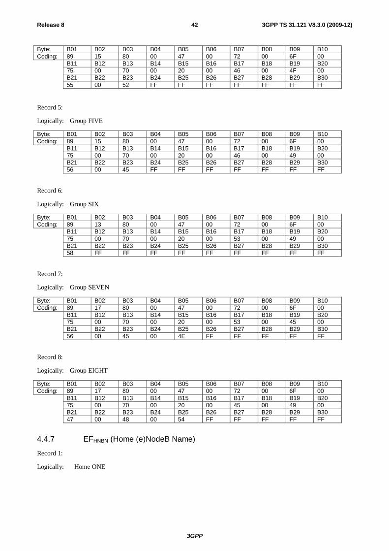
3GPP
Release 8 42 3GPP TS 31.121 V8.3.0 (2009-12)
Byte: B01 B02 B03 B04 B05 B06 B07 B08 B09 B10 Coding: 89 15 80 00 47 00 72 00 6F 00 B11 B12 B13 B14 B15 B16 B17 B18 B19 B20 75 00 70 00 20 00 46 00 4F 00 B21 B22 B23 B24 B25 B26 B27 B28 B29 B30 55 00 52 FF FF FF FF FF FF FF
Record 5:
Logically: Group FIVE
Byte: B01 B02 B03 B04 B05 B06 B07 B08 B09 B10 Coding: 89 15 80 00 47 00 72 00 6F 00 B11 B12 B13 B14 B15 B16 B17 B18 B19 B20 75 00 70 00 20 00 46 00 49 00 B21 B22 B23 B24 B25 B26 B27 B28 B29 B30 56 00 45 FF FF FF FF FF FF FF
Record 6:
Logically: Group SIX
Byte: B01 B02 B03 B04 B05 B06 B07 B08 B09 B10 Coding: 89 13 80 00 47 00 72 00 6F 00 B11 B12 B13 B14 B15 B16 B17 B18 B19 B20 75 00 70 00 20 00 53 00 49 00 B21 B22 B23 B24 B25 B26 B27 B28 B29 B30 58 FF FF FF FF FF FF FF FF FF
Record 7:
Logically: Group SEVEN
Byte: B01 B02 B03 B04 B05 B06 B07 B08 B09 B10 Coding: 89 17 80 00 47 00 72 00 6F 00 B11 B12 B13 B14 B15 B16 B17 B18 B19 B20 75 00 70 00 20 00 53 00 45 00 B21 B22 B23 B24 B25 B26 B27 B28 B29 B30 56 00 45 00 4E FF FF FF FF FF
Record 8:
Logically: Group EIGHT
Byte: B01 B02 B03 B04 B05 B06 B07 B08 B09 B10 Coding: 89 17 80 00 47 00 72 00 6F 00 B11 B12 B13 B14 B15 B16 B17 B18 B19 B20 75 00 70 00 20 00 45 00 49 00 B21 B22 B23 B24 B25 B26 B27 B28 B29 B30 47 00 48 00 54 FF FF FF FF FF
4.4.7 EFHNBN (Home (e)NodeB Name)
Record 1:
Logically: Home ONE
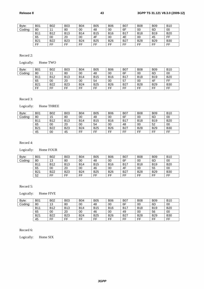
3GPP
Release 8 43 3GPP TS 31.121 V8.3.0 (2009-12)
Byte: B01 B02 B03 B04 B05 B06 B07 B08 B09 B10 Coding: 80 11 80 00 48 00 6F 00 6D 00 B11 B12 B13 B14 B15 B16 B17 B18 B19 B20 65 00 20 00 4F 00 4E 00 45 FF B21 B22 B23 B24 B25 B26 B27 B28 B29 B30 FF FF FF FF FF FF FF FF FF FF
Record 2:
Logically: Home TWO
Byte: B01 B02 B03 B04 B05 B06 B07 B08 B09 B10 Coding: 80 11 80 00 48 00 6F 00 6D 00 B11 B12 B13 B14 B15 B16 B17 B18 B19 B20 65 00 20 00 54 00 57 00 4F FF B21 B22 B23 B24 B25 B26 B27 B28 B29 B30 FF FF FF FF FF FF FF FF FF FF
Record 3:
Logically: Home THREE
Byte: B01 B02 B03 B04 B05 B06 B07 B08 B09 B10 Coding: 80 15 80 00 48 00 6F 00 6D 00 B11 B12 B13 B14 B15 B16 B17 B18 B19 B20 65 00 20 00 54 00 48 00 52 00 B21 B22 B23 B24 B25 B26 B27 B28 B29 B30 45 00 45 FF FF FF FF FF FF FF
Record 4:
Logically: Home FOUR
Byte: B01 B02 B03 B04 B05 B06 B07 B08 B09 B10 Coding: 80 13 80 00 48 00 6F 00 6D 00 B11 B12 B13 B14 B15 B16 B17 B18 B19 B20 65 00 20 00 46 00 4F 00 55 00 B21 B22 B23 B24 B25 B26 B27 B28 B29 B30 52 FF FF FF FF FF FF FF FF FF
Record 5:
Logically: Home FIVE
Byte: B01 B02 B03 B04 B05 B06 B07 B08 B09 B10 Coding: 80 13 80 00 48 00 6F 00 6D 00 B11 B12 B13 B14 B15 B16 B17 B18 B19 B20 65 00 20 00 46 00 49 00 56 00 B21 B22 B23 B24 B25 B26 B27 B28 B29 B30 45 FF FF FF FF FF FF FF FF FF
Record 6:
Logically: Home SIX
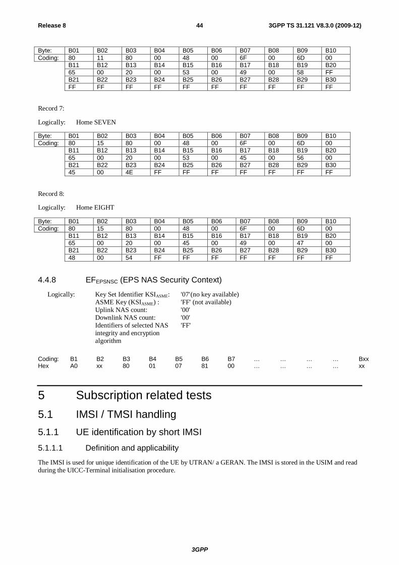
3GPP
Release 8 44 3GPP TS 31.121 V8.3.0 (2009-12)
Byte: B01 B02 B03 B04 B05 B06 B07 B08 B09 B10 Coding: 80 11 80 00 48 00 6F 00 6D 00 B11 B12 B13 B14 B15 B16 B17 B18 B19 B20 65 00 20 00 53 00 49 00 58 FF B21 B22 B23 B24 B25 B26 B27 B28 B29 B30 FF FF FF FF FF FF FF FF FF FF
Record 7:
Logically: Home SEVEN
Byte: B01 B02 B03 B04 B05 B06 B07 B08 B09 B10 Coding: 80 15 80 00 48 00 6F 00 6D 00 B11 B12 B13 B14 B15 B16 B17 B18 B19 B20 65 00 20 00 53 00 45 00 56 00 B21 B22 B23 B24 B25 B26 B27 B28 B29 B30 45 00 4E FF FF FF FF FF FF FF
Record 8:
Logically: Home EIGHT
Byte: B01 B02 B03 B04 B05 B06 B07 B08 B09 B10 Coding: 80 15 80 00 48 00 6F 00 6D 00 B11 B12 B13 B14 B15 B16 B17 B18 B19 B20 65 00 20 00 45 00 49 00 47 00 B21 B22 B23 B24 B25 B26 B27 B28 B29 B30 48 00 54 FF FF FF FF FF FF FF
4.4.8 EFEPSNSC (EPS NAS Security Context)
Logically: Key Set Identifier KSIASME: '07' (no key available) ASME Key (KSIASME) : 'FF' (not available) Uplink NAS count: '00' Downlink NAS count: '00' Identifiers of selected NAS 'FF'
integrity and encryption algorithm
Coding: B1 B2 B3 B4 B5 B6 B7 … … … … Bxx Hex A0 xx 80 01 07 81 00 … … … … xx
5 Subscription related tests 5.1 IMSI / TMSI handling 5.1.1 UE identification by short IMSI 5.1.1.1 Definition and applicability
The IMSI is used for unique identification of the UE by UTRAN/ a GERAN. The IMSI is stored in the USIM and read during the UICC-Terminal initialisation procedure.

3GPP
Release 8 45 3GPP TS 31.121 V8.3.0 (2009-12)
5.1.1.2 Conformance requirement
After successful completion of the RRC Connection Establishment procedure (in case of Terminals accessing UTRAN) respectively after receipt of an IMMEDIATE ASSIGNMENT message (in case of a Terminal accessing a GERAN) the UE shall send PAGING RESPONSE containing the IMSI of the USIM, which is less than the maximum length.
Reference:
- TS 31.102 [4], subclauses 5.1.1 and 5.2.2;
- TS 24.008 [16], subclause 10.5.1.4;
- ETSI TS 102 221 [5], subclause 14.1.1.
5.1.1.3 Test purpose
1) To verify that the Terminal uses the IMSI of the USIM.
2) To verify that the Terminal can handle an IMSI of less than the maximum length.
3) To verify that the READ EFIMSI command is performed correctly by the terminal
5.1.1.4 Method of test
5.1.1.4.1 Initial conditions
The USS (in case of a Terminal accessing UTRAN) / SS (in case of a Terminal accessing a GERAN) transmits on the BCCH, with the following network parameters:
- Attach/detach: disabled.
- LAI (MCC/MNC/LAC): 246/081/0001.
- Access control: unrestricted.
The default UICC is installed into the Terminal and the UE is powered on.
In case of a Terminal accessing UTRAN "Expected Sequence A" and in case of a Terminal accessing a GERAN "Expected Sequence B" shall be performed.
5.1.1.4.2 Procedure
Expected Sequence A:
a) The USS sends PAGING TYPE 1 to the UE using the IMSI stored in the USIM.
b) After receipt of a RRC CONNECTION REQUEST from the UE, the USS sends RRC CONNECTION SETUP to the UE, followed by RRC CONNECTION SETUP COMPLETE sent by the UE to the USS.
c) After receipt of a PAGING RESPONSE from the UE, the USS sends RRC CONNECTION RELEASE to the UE, followed by RRC CONNECTION RELEASE COMPLETE sent by the UE to the USS.
Expected Sequence B:
a) The SS sends PAGING REQUEST to the UE using the IMSI stored in the USIM.
b) After receipt of a CHANNEL REQUEST from the UE, the SS sends IMMEDIATE ASSIGNMENT to the UE.
c) After receipt of a PAGING RESPONSE from the UE, the SS sends CHANNEL RELEASE to the UE.
5.1.1.5 Acceptance criteria
After step b) the UE shall send PAGING RESPONSE to the USS/SS containing the IMSI stored in the USIM.
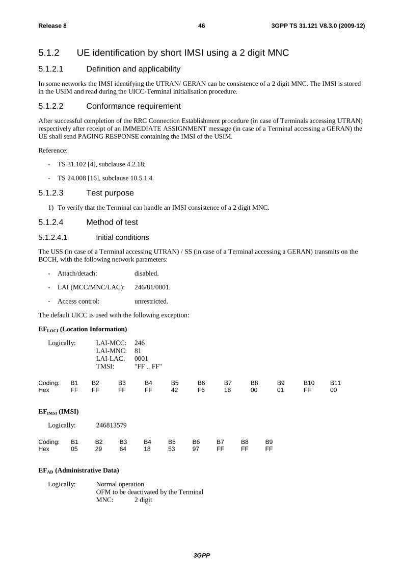
3GPP
Release 8 46 3GPP TS 31.121 V8.3.0 (2009-12)
5.1.2 UE identification by short IMSI using a 2 digit MNC
5.1.2.1 Definition and applicability
In some networks the IMSI identifying the UTRAN/ GERAN can be consistence of a 2 digit MNC. The IMSI is stored in the USIM and read during the UICC-Terminal initialisation procedure.
5.1.2.2 Conformance requirement
After successful completion of the RRC Connection Establishment procedure (in case of Terminals accessing UTRAN) respectively after receipt of an IMMEDIATE ASSIGNMENT message (in case of a Terminal accessing a GERAN) the UE shall send PAGING RESPONSE containing the IMSI of the USIM.
Reference:
- TS 31.102 [4], subclause 4.2.18;
- TS 24.008 [16], subclause 10.5.1.4.
5.1.2.3 Test purpose
1) To verify that the Terminal can handle an IMSI consistence of a 2 digit MNC.
5.1.2.4 Method of test
5.1.2.4.1 Initial conditions
The USS (in case of a Terminal accessing UTRAN) / SS (in case of a Terminal accessing a GERAN) transmits on the BCCH, with the following network parameters:
- Attach/detach: disabled.
- LAI (MCC/MNC/LAC): 246/81/0001.
- Access control: unrestricted.
The default UICC is used with the following exception:
EFLOCI (Location Information)
Logically: LAI-MCC: 246 LAI-MNC: 81 LAI-LAC: 0001 TMSI: "FF .. FF"
Coding: B1 B2 B3 B4 B5 B6 B7 B8 B9 B10 B11 Hex FF FF FF FF 42 F6 18 00 01 FF 00
EFIMSI (IMSI)
Logically: 246813579
Coding: B1 B2 B3 B4 B5 B6 B7 B8 B9 Hex 05 29 64 18 53 97 FF FF FF
EFAD (Administrative Data)
Logically: Normal operation OFM to be deactivated by the Terminal MNC: 2 digit
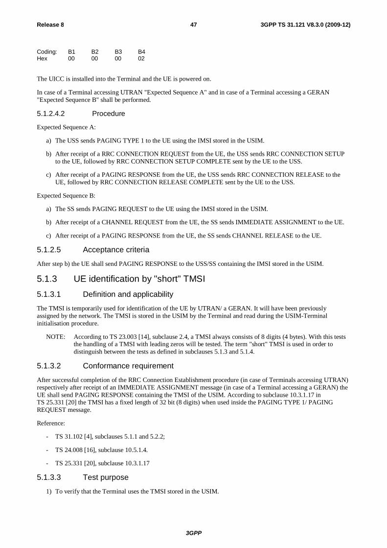
3GPP
Release 8 47 3GPP TS 31.121 V8.3.0 (2009-12)
Coding: B1 B2 B3 B4 Hex 00 00 00 02
The UICC is installed into the Terminal and the UE is powered on.
In case of a Terminal accessing UTRAN "Expected Sequence A" and in case of a Terminal accessing a GERAN "Expected Sequence B" shall be performed.
5.1.2.4.2 Procedure
Expected Sequence A:
a) The USS sends PAGING TYPE 1 to the UE using the IMSI stored in the USIM.
b) After receipt of a RRC CONNECTION REQUEST from the UE, the USS sends RRC CONNECTION SETUP to the UE, followed by RRC CONNECTION SETUP COMPLETE sent by the UE to the USS.
c) After receipt of a PAGING RESPONSE from the UE, the USS sends RRC CONNECTION RELEASE to the UE, followed by RRC CONNECTION RELEASE COMPLETE sent by the UE to the USS.
Expected Sequence B:
a) The SS sends PAGING REQUEST to the UE using the IMSI stored in the USIM.
b) After receipt of a CHANNEL REQUEST from the UE, the SS sends IMMEDIATE ASSIGNMENT to the UE.
c) After receipt of a PAGING RESPONSE from the UE, the SS sends CHANNEL RELEASE to the UE.
5.1.2.5 Acceptance criteria
After step b) the UE shall send PAGING RESPONSE to the USS/SS containing the IMSI stored in the USIM.
5.1.3 UE identification by "short" TMSI 5.1.3.1 Definition and applicability
The TMSI is temporarily used for identification of the UE by UTRAN/ a GERAN. It will have been previously assigned by the network. The TMSI is stored in the USIM by the Terminal and read during the USIM-Terminal initialisation procedure.
NOTE: According to TS 23.003 [14], subclause 2.4, a TMSI always consists of 8 digits (4 bytes). With this tests the handling of a TMSI with leading zeros will be tested. The term "short" TMSI is used in order to distinguish between the tests as defined in subclauses 5.1.3 and 5.1.4.
5.1.3.2 Conformance requirement
After successful completion of the RRC Connection Establishment procedure (in case of Terminals accessing UTRAN) respectively after receipt of an IMMEDIATE ASSIGNMENT message (in case of a Terminal accessing a GERAN) the UE shall send PAGING RESPONSE containing the TMSI of the USIM. According to subclause 10.3.1.17 in TS 25.331 [20] the TMSI has a fixed length of 32 bit (8 digits) when used inside the PAGING TYPE 1/ PAGING REQUEST message.
Reference:
- TS 31.102 [4], subclauses 5.1.1 and 5.2.2;
- TS 24.008 [16], subclause 10.5.1.4.
- TS 25.331 [20], subclause 10.3.1.17
5.1.3.3 Test purpose
1) To verify that the Terminal uses the TMSI stored in the USIM.
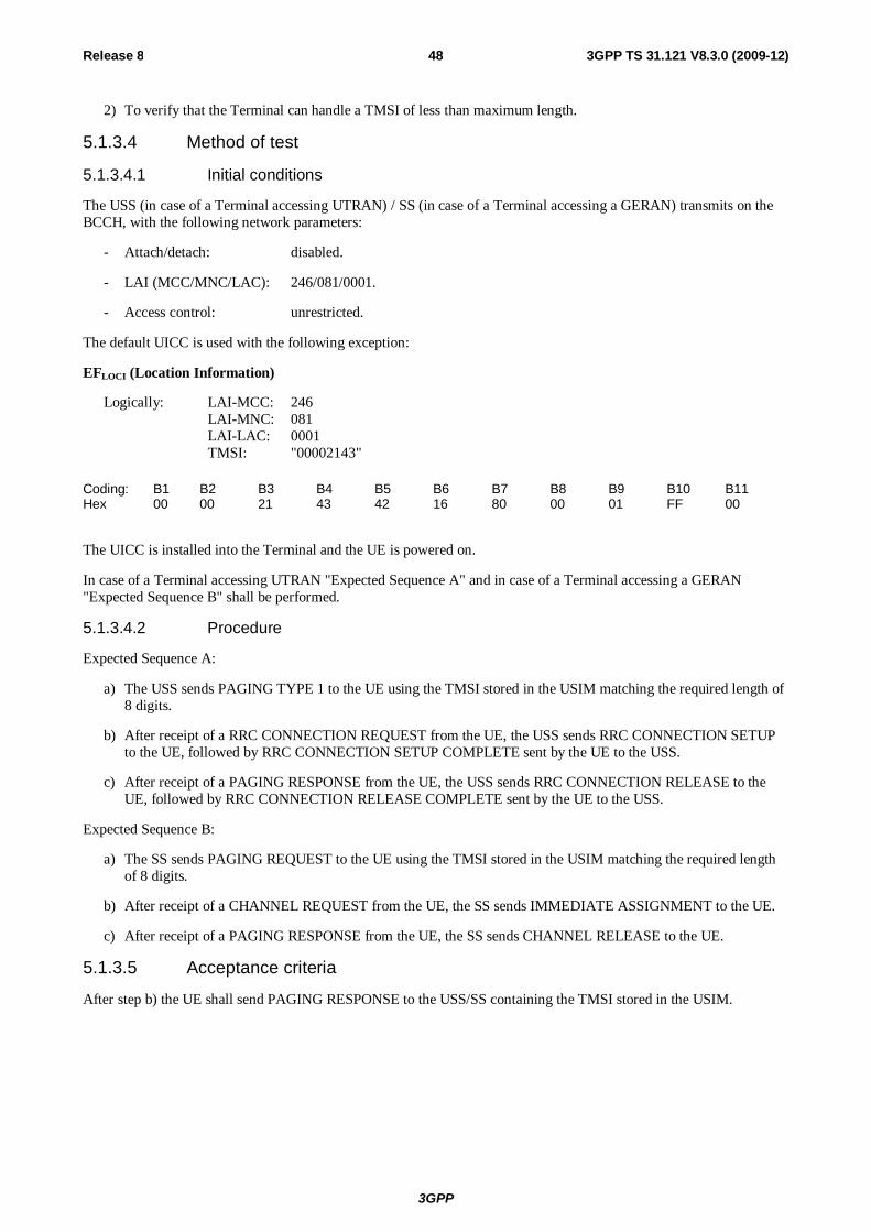
3GPP
Release 8 48 3GPP TS 31.121 V8.3.0 (2009-12)
2) To verify that the Terminal can handle a TMSI of less than maximum length.
5.1.3.4 Method of test
5.1.3.4.1 Initial conditions
The USS (in case of a Terminal accessing UTRAN) / SS (in case of a Terminal accessing a GERAN) transmits on the BCCH, with the following network parameters:
- Attach/detach: disabled.
- LAI (MCC/MNC/LAC): 246/081/0001.
- Access control: unrestricted.
The default UICC is used with the following exception:
EFLOCI (Location Information)
Logically: LAI-MCC: 246 LAI-MNC: 081 LAI-LAC: 0001 TMSI: "00002143"
Coding: B1 B2 B3 B4 B5 B6 B7 B8 B9 B10 B11 Hex 00 00 21 43 42 16 80 00 01 FF 00
The UICC is installed into the Terminal and the UE is powered on.
In case of a Terminal accessing UTRAN "Expected Sequence A" and in case of a Terminal accessing a GERAN "Expected Sequence B" shall be performed.
5.1.3.4.2 Procedure
Expected Sequence A:
a) The USS sends PAGING TYPE 1 to the UE using the TMSI stored in the USIM matching the required length of 8 digits.
b) After receipt of a RRC CONNECTION REQUEST from the UE, the USS sends RRC CONNECTION SETUP to the UE, followed by RRC CONNECTION SETUP COMPLETE sent by the UE to the USS.
c) After receipt of a PAGING RESPONSE from the UE, the USS sends RRC CONNECTION RELEASE to the UE, followed by RRC CONNECTION RELEASE COMPLETE sent by the UE to the USS.
Expected Sequence B:
a) The SS sends PAGING REQUEST to the UE using the TMSI stored in the USIM matching the required length of 8 digits.
b) After receipt of a CHANNEL REQUEST from the UE, the SS sends IMMEDIATE ASSIGNMENT to the UE.
c) After receipt of a PAGING RESPONSE from the UE, the SS sends CHANNEL RELEASE to the UE.
5.1.3.5 Acceptance criteria
After step b) the UE shall send PAGING RESPONSE to the USS/SS containing the TMSI stored in the USIM.
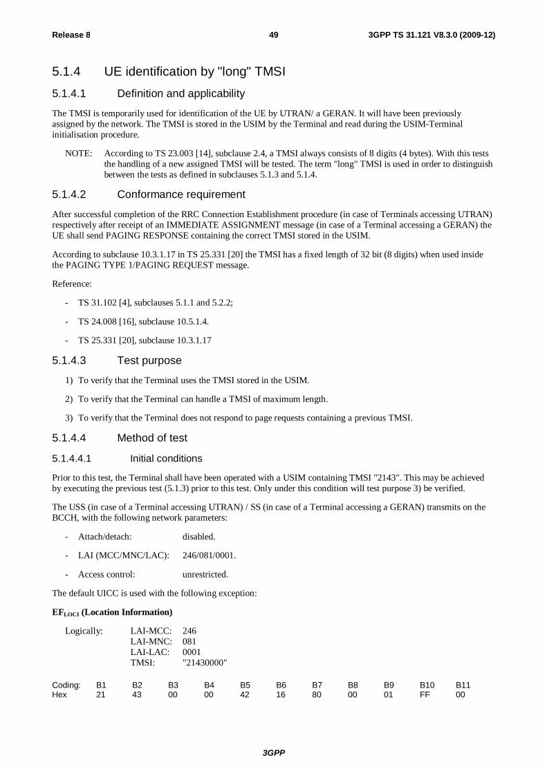
3GPP
Release 8 49 3GPP TS 31.121 V8.3.0 (2009-12)
5.1.4 UE identification by "long" TMSI
5.1.4.1 Definition and applicability
The TMSI is temporarily used for identification of the UE by UTRAN/ a GERAN. It will have been previously assigned by the network. The TMSI is stored in the USIM by the Terminal and read during the USIM-Terminal initialisation procedure.
NOTE: According to TS 23.003 [14], subclause 2.4, a TMSI always consists of 8 digits (4 bytes). With this tests the handling of a new assigned TMSI will be tested. The term "long" TMSI is used in order to distinguish between the tests as defined in subclauses 5.1.3 and 5.1.4.
5.1.4.2 Conformance requirement
After successful completion of the RRC Connection Establishment procedure (in case of Terminals accessing UTRAN) respectively after receipt of an IMMEDIATE ASSIGNMENT message (in case of a Terminal accessing a GERAN) the UE shall send PAGING RESPONSE containing the correct TMSI stored in the USIM.
According to subclause 10.3.1.17 in TS 25.331 [20] the TMSI has a fixed length of 32 bit (8 digits) when used inside the PAGING TYPE 1/PAGING REQUEST message.
Reference:
- TS 31.102 [4], subclauses 5.1.1 and 5.2.2;
- TS 24.008 [16], subclause 10.5.1.4.
- TS 25.331 [20], subclause 10.3.1.17
5.1.4.3 Test purpose
1) To verify that the Terminal uses the TMSI stored in the USIM.
2) To verify that the Terminal can handle a TMSI of maximum length.
3) To verify that the Terminal does not respond to page requests containing a previous TMSI.
5.1.4.4 Method of test
5.1.4.4.1 Initial conditions
Prior to this test, the Terminal shall have been operated with a USIM containing TMSI "2143". This may be achieved by executing the previous test (5.1.3) prior to this test. Only under this condition will test purpose 3) be verified.
The USS (in case of a Terminal accessing UTRAN) / SS (in case of a Terminal accessing a GERAN) transmits on the BCCH, with the following network parameters:
- Attach/detach: disabled.
- LAI (MCC/MNC/LAC): 246/081/0001.
- Access control: unrestricted.
The default UICC is used with the following exception:
EFLOCI (Location Information)
Logically: LAI-MCC: 246 LAI-MNC: 081 LAI-LAC: 0001 TMSI: "21430000"
Coding: B1 B2 B3 B4 B5 B6 B7 B8 B9 B10 B11 Hex 21 43 00 00 42 16 80 00 01 FF 00

3GPP
Release 8 50 3GPP TS 31.121 V8.3.0 (2009-12)
The UICC is installed into the Terminal and the UE is powered on.
In case of a Terminal accessing UTRAN "Expected Sequence A" and in case of a Terminal accessing a GERAN "Expected Sequence B" shall be performed.
5.1.4.4.2 Procedure
Expected Sequence A:
a) The USS sends PAGING TYPE 1 to the UE using the TMSI "00002143".
b) The USS sends PAGING TYPE 1 to the UE using the TMSI stored in the USIM.
c) After receipt of a RRC CONNECTION REQUEST from the UE, the USS sends RRC CONNECTION SETUP to the UE, followed by RRC CONNECTION SETUP COMPLETE sent by the UE to the USS.
d) After receipt of a PAGING RESPONSE from the UE, the USS sends RRC CONNECTION RELEASE to the UE, followed by RRC CONNECTION RELEASE COMPLETE sent by the UE to the USS.
Expected Sequence B:
a) The SS sends PAGING REQUEST to the UE using the TMSI "00002143".
b) The SS sends PAGING REQUEST to the UE using the TMSI stored in the USIM.
c) After receipt of a CHANNEL REQUEST from the UE, the SS sends IMMEDIATE ASSIGNMENT to the UE.
d) After receipt of a PAGING RESPONSE from the UE, the SS sends CHANNEL RELEASE to the UE.
5.1.4.5 Acceptance criteria
1) After step a) the UE shall not respond to the PAGING TYPE 1 respectively to the PAGING REQUEST.
2) After step c) the UE shall send PAGING RESPONSE to the USS/ SS containing the TMSI stored in the USIM.
5.1.5 UE identification by long IMSI, TMSI updating and key set identifier assignment
5.1.5.1 Definition and applicability
The IMSI and TMSI are used for identification of the UE by UTRAN/ a GERAN. They are read from the USIM during the USIM-Terminal initialisation procedure. Within the authentication procedure the UTRAN sends a key set identifier respectively a GERAN sends a ciphering key sequence number to the UE. In addition the network may allocate a new TMSI to the UE. Key set identifier and TMSI are stored in the USIM after UTRAN call termination and/or at a 3G session termination. Ciphering key sequence number and TMSI are stored in the USIM after GERAN call termination and/or at a 3G session termination.
NOTE: According to TS 24.008 [16] the term KSI may be used instead of the term ciphering key sequence number which is used inside the MM message AUTHENTICATION REQUEST.
5.1.5.2 Conformance requirement
1) After successful completion of the RRC Connection Establishment procedure (in case of Terminals accessing UTRAN) respectively after receipt of an IMMEDIATE ASSIGNMENT message (in case of a Terminal accessing a GERAN) the UE shall send PAGING RESPONSE containing the correct IMSI stored in the USIM.
Reference:
- TS 31.102 [4], subclauses 5.1.1 and 5.2.2;
- TS 24.008 [16], subclause 10.5.1.4.
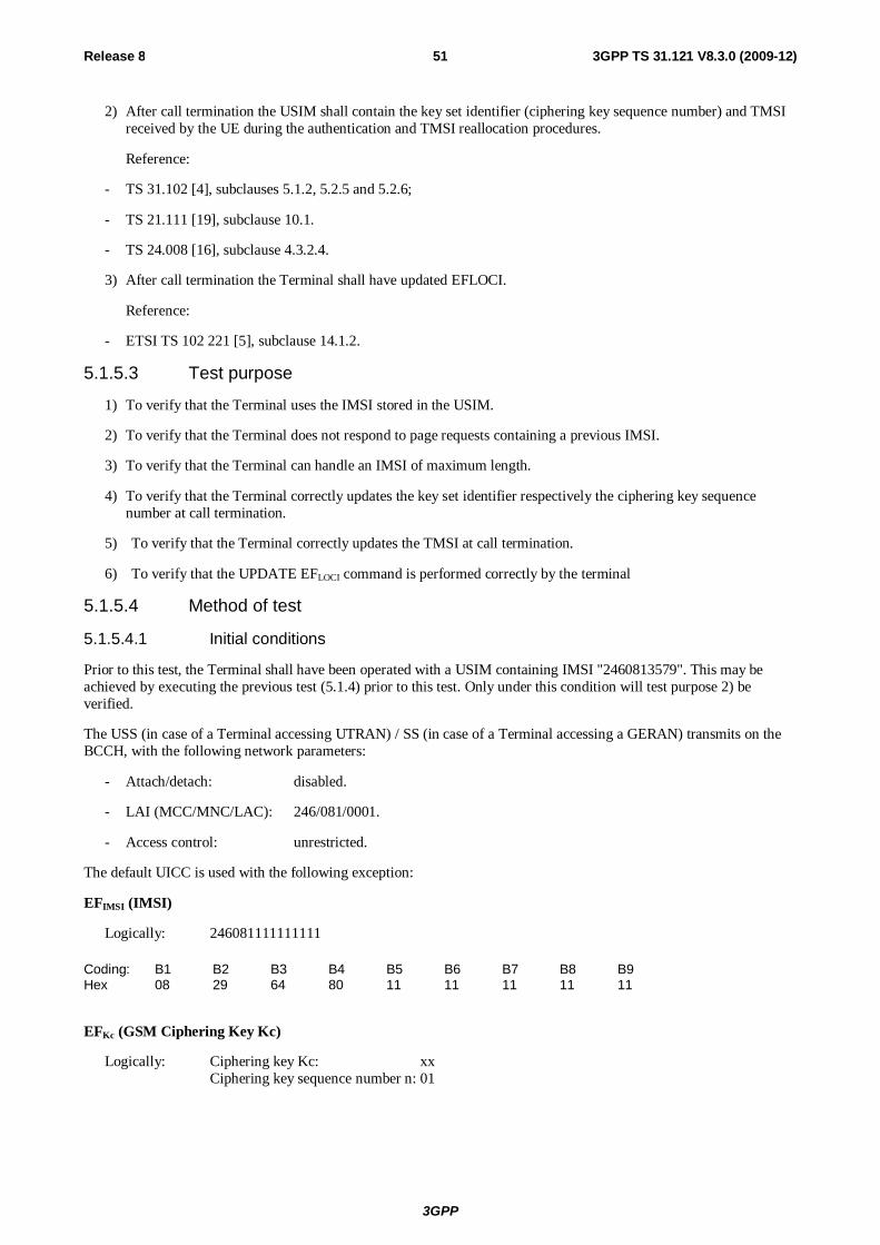
3GPP
Release 8 51 3GPP TS 31.121 V8.3.0 (2009-12)
2) After call termination the USIM shall contain the key set identifier (ciphering key sequence number) and TMSI received by the UE during the authentication and TMSI reallocation procedures.
Reference:
- TS 31.102 [4], subclauses 5.1.2, 5.2.5 and 5.2.6;
- TS 21.111 [19], subclause 10.1.
- TS 24.008 [16], subclause 4.3.2.4.
3) After call termination the Terminal shall have updated EFLOCI.
Reference:
- ETSI TS 102 221 [5], subclause 14.1.2.
5.1.5.3 Test purpose
1) To verify that the Terminal uses the IMSI stored in the USIM.
2) To verify that the Terminal does not respond to page requests containing a previous IMSI.
3) To verify that the Terminal can handle an IMSI of maximum length.
4) To verify that the Terminal correctly updates the key set identifier respectively the ciphering key sequence number at call termination.
5) To verify that the Terminal correctly updates the TMSI at call termination.
6) To verify that the UPDATE EFLOCI command is performed correctly by the terminal
5.1.5.4 Method of test
5.1.5.4.1 Initial conditions
Prior to this test, the Terminal shall have been operated with a USIM containing IMSI "2460813579". This may be achieved by executing the previous test (5.1.4) prior to this test. Only under this condition will test purpose 2) be verified.
The USS (in case of a Terminal accessing UTRAN) / SS (in case of a Terminal accessing a GERAN) transmits on the BCCH, with the following network parameters:
- Attach/detach: disabled.
- LAI (MCC/MNC/LAC): 246/081/0001.
- Access control: unrestricted.
The default UICC is used with the following exception:
EFIMSI (IMSI)
Logically: 246081111111111
Coding: B1 B2 B3 B4 B5 B6 B7 B8 B9 Hex 08 29 64 80 11 11 11 11 11
EFKc (GSM Ciphering Key Kc)
Logically: Ciphering key Kc: xx Ciphering key sequence number n: 01
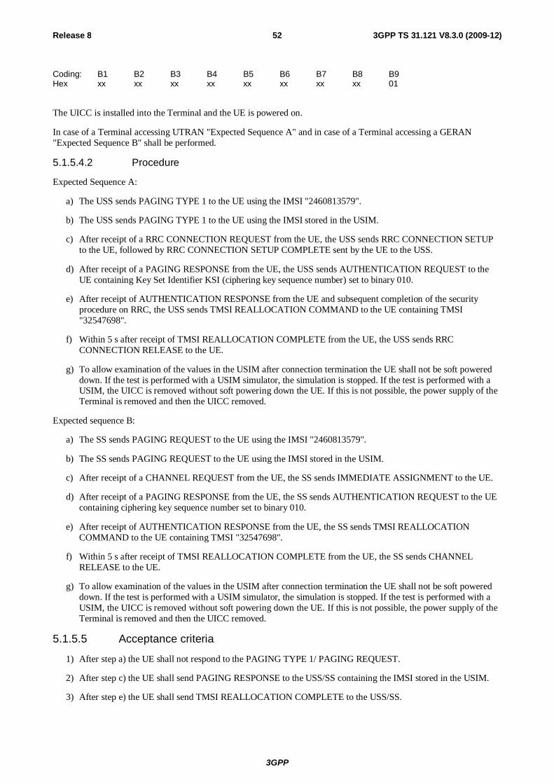
3GPP
Release 8 52 3GPP TS 31.121 V8.3.0 (2009-12)
Coding: B1 B2 B3 B4 B5 B6 B7 B8 B9 Hex xx xx xx xx xx xx xx xx 01
The UICC is installed into the Terminal and the UE is powered on.
In case of a Terminal accessing UTRAN "Expected Sequence A" and in case of a Terminal accessing a GERAN "Expected Sequence B" shall be performed.
5.1.5.4.2 Procedure
Expected Sequence A:
a) The USS sends PAGING TYPE 1 to the UE using the IMSI "2460813579".
b) The USS sends PAGING TYPE 1 to the UE using the IMSI stored in the USIM.
c) After receipt of a RRC CONNECTION REQUEST from the UE, the USS sends RRC CONNECTION SETUP to the UE, followed by RRC CONNECTION SETUP COMPLETE sent by the UE to the USS.
d) After receipt of a PAGING RESPONSE from the UE, the USS sends AUTHENTICATION REQUEST to the UE containing Key Set Identifier KSI (ciphering key sequence number) set to binary 010.
e) After receipt of AUTHENTICATION RESPONSE from the UE and subsequent completion of the security procedure on RRC, the USS sends TMSI REALLOCATION COMMAND to the UE containing TMSI "32547698".
f) Within 5 s after receipt of TMSI REALLOCATION COMPLETE from the UE, the USS sends RRC CONNECTION RELEASE to the UE.
g) To allow examination of the values in the USIM after connection termination the UE shall not be soft powered down. If the test is performed with a USIM simulator, the simulation is stopped. If the test is performed with a USIM, the UICC is removed without soft powering down the UE. If this is not possible, the power supply of the Terminal is removed and then the UICC removed.
Expected sequence B:
a) The SS sends PAGING REQUEST to the UE using the IMSI "2460813579".
b) The SS sends PAGING REQUEST to the UE using the IMSI stored in the USIM.
c) After receipt of a CHANNEL REQUEST from the UE, the SS sends IMMEDIATE ASSIGNMENT to the UE.
d) After receipt of a PAGING RESPONSE from the UE, the SS sends AUTHENTICATION REQUEST to the UE containing ciphering key sequence number set to binary 010.
e) After receipt of AUTHENTICATION RESPONSE from the UE, the SS sends TMSI REALLOCATION COMMAND to the UE containing TMSI "32547698".
f) Within 5 s after receipt of TMSI REALLOCATION COMPLETE from the UE, the SS sends CHANNEL RELEASE to the UE.
g) To allow examination of the values in the USIM after connection termination the UE shall not be soft powered down. If the test is performed with a USIM simulator, the simulation is stopped. If the test is performed with a USIM, the UICC is removed without soft powering down the UE. If this is not possible, the power supply of the Terminal is removed and then the UICC removed.
5.1.5.5 Acceptance criteria
1) After step a) the UE shall not respond to the PAGING TYPE 1/ PAGING REQUEST.
2) After step c) the UE shall send PAGING RESPONSE to the USS/SS containing the IMSI stored in the USIM.
3) After step e) the UE shall send TMSI REALLOCATION COMPLETE to the USS/SS.
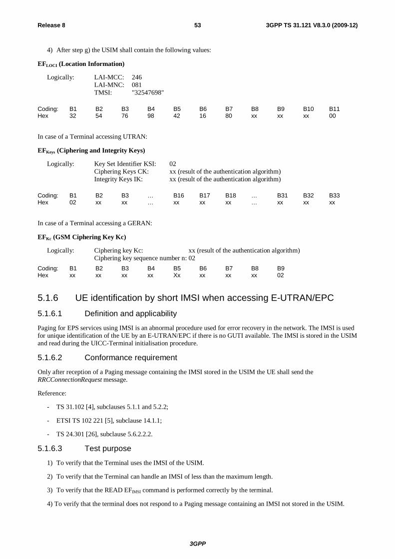
3GPP
Release 8 53 3GPP TS 31.121 V8.3.0 (2009-12)
4) After step g) the USIM shall contain the following values:
EFLOCI (Location Information)
Logically: LAI-MCC: 246 LAI-MNC: 081 TMSI: "32547698"
Coding: B1 B2 B3 B4 B5 B6 B7 B8 B9 B10 B11 Hex 32 54 76 98 42 16 80 xx xx xx 00
In case of a Terminal accessing UTRAN:
EFKeys (Ciphering and Integrity Keys)
Logically: Key Set Identifier KSI: 02 Ciphering Keys CK: xx (result of the authentication algorithm) Integrity Keys IK: xx (result of the authentication algorithm)
Coding: B1 B2 B3 … B16 B17 B18 … B31 B32 B33 Hex 02 xx xx … xx xx xx … xx xx xx
In case of a Terminal accessing a GERAN:
EFKc (GSM Ciphering Key Kc)
Logically: Ciphering key Kc: xx (result of the authentication algorithm) Ciphering key sequence number n: 02
Coding: B1 B2 B3 B4 B5 B6 B7 B8 B9 Hex xx xx xx xx Xx xx xx xx 02
5.1.6 UE identification by short IMSI when accessing E-UTRAN/EPC 5.1.6.1 Definition and applicability
Paging for EPS services using IMSI is an abnormal procedure used for error recovery in the network. The IMSI is used for unique identification of the UE by an E-UTRAN/EPC if there is no GUTI available. The IMSI is stored in the USIM and read during the UICC-Terminal initialisation procedure.
5.1.6.2 Conformance requirement
Only after reception of a Paging message containing the IMSI stored in the USIM the UE shall send the RRCConnectionRequest message.
Reference:
- TS 31.102 [4], subclauses 5.1.1 and 5.2.2;
- ETSI TS 102 221 [5], subclause 14.1.1;
- TS 24.301 [26], subclause 5.6.2.2.2.
5.1.6.3 Test purpose
1) To verify that the Terminal uses the IMSI of the USIM.
2) To verify that the Terminal can handle an IMSI of less than the maximum length.
3) To verify that the READ EFIMSI command is performed correctly by the terminal.
4) To verify that the terminal does not respond to a Paging message containing an IMSI not stored in the USIM.
3GPP
Release 8 54 3GPP TS 31.121 V8.3.0 (2009-12)
5.1.6.4 Method of test
5.1.6.4.1 Initial conditions
The E-USS transmits on the BCCH, with the following network parameters:
- TAI (MCC/MNC/TAC): 246/081/0001.
- Access control: unrestricted.
The default E-UTRAN UICC is installed into the Terminal and the UE is powered on.
5.1.6.4.2 Procedure
a) The UE performs Attach procedure to E-USS.
b) The E-USS sends Paging to the UE using the IMSI 24608122222.
c) The E-USS sends Paging to the UE using the IMSI stored in the USIM.
d) After receipt of a RRCConnectionRequest message from the UE, the E-USS sends RRCConnectionSetup message to the UE, followed by RRCConnectionSetupComplete sent by the UE to the E-USS.
e) After the EPS attach procedure the E-USS sends RRCConnectionRelease to the UE.
5.1.6.5 Acceptance criteria
1) After step b) the UE shall not send RRCConnectionRequest to the E-USS.
2) After step c) the UE shall send RRCConnectionRequest to the E-USS.
3) After step d) the UE performs the EPS attach procedure.
5.1.7 UE identification by short IMSI using a 2 digit MNC when accessing E-UTRAN/EPC
5.1.7.1 Definition and applicability
In some networks the IMSI identifying the E-UTRAN/EPC can be consistence of a 2 digit MNC. Paging for EPS services using IMSI is an abnormal procedure used for error recovery in the network. The IMSI is used for unique identification of the UE by an E-UTRAN/EPC if there is no GUTI available. The IMSI is stored in the USIM and read during the UICC-Terminal initialisation procedure.
5.1.7.2 Conformance requirement
Only after reception of a Paging message containing the IMSI stored in the USIM the UE shall send the RRCConnectionRequest message.
Reference:
- TS 31.102 [4], subclauses 5.1.1 and 5.2.2;
- ETSI TS 102 221 [5], subclause 14.1.1;
- TS 24.301 [26], subclause 5.6.2.2.2.
5.1.7.3 Test purpose
1) To verify that the Terminal uses the IMSI of the USIM.
2) To verify that the Terminal can handle an IMSI consistence of a 2 digit MNC.
3GPP
Release 8 55 3GPP TS 31.121 V8.3.0 (2009-12)
3) To verify that the READ EFIMSI command is performed correctly by the terminal.
4) To verify that the terminal does not respond to a Paging message containing an IMSI not stored in the USIM.
5.1.7.4 Method of test
5.1.7.4.1 Initial conditions
The E-USS transmits on the BCCH, with the following network parameters:
- TAI (MCC/MNC/TAC): 246/81/0001.
- Access control: unrestricted.
The default UICC is used with the following exception:
EFIMSI (IMSI)
Logically: 246813579
Coding: B1 B2 B3 B4 B5 B6 B7 B8 B9 Hex 05 29 64 18 53 97 FF FF FF
EFAD (Administrative Data)
Logically: Normal operation OFM to be deactivated by the Terminal MNC: 2 digit
Coding: B1 B2 B3 B4 Hex 00 00 00 02
The UICC is installed into the Terminal and the UE is powered on.
5.1.7.4.2 Procedure
a) The UE performs Attach procedure to E-USS.
b) The E-USS sends Paging to the UE using the IMSI 24608122222.
c) The E-USS sends Paging to the UE using the IMSI stored in the USIM.
d) After receipt of a RRCConnectionRequest message from the UE, the E-USS sends RRCConnectionSetup message to the UE, followed by RRCConnectionSetupComplete sent by the UE to the E-USS.
e) After the EPS attach procedure the E-USS sends RRCConnectionRelease to the UE.
5.1.7.5 Acceptance criteria
1) After step b) the UE shall not send RRCConnectionRequest to the E-USS.
2) After step c) the UE shall send RRCConnectionRequest to the E-USS.
3) After step d) the UE performs the EPS attach procedure.
5.1.8 UE identification after changed IMSI with service "EMM Information" not available
The attach procedure is used to attach for packet services in EPS. With a successful attach procedure, a context is established for the UE in the MME, and a default bearer is established between the UE and the PDN GW, thus enabling
3GPP
Release 8 56 3GPP TS 31.121 V8.3.0 (2009-12)
always-on IP connectivity to the UE. The network may also initiate the activation of dedicated bearers as part of the attach procedure.
5.1.8.2 Conformance requirement
The following EMM parameters shall be stored on the USIM if the corresponding file is present:
- GUTI;
- last visited registered TAI;
- EPS update status.
If the corresponding file is not present on the USIM, these EMM parameters except allowed CSG list are stored in a non-volatile memory in the ME together with the IMSI from the USIM. These EMM parameters can only be used if the IMSI from the USIM matches the IMSI stored in the non-volatile memory; else the UE shall delete the EMM parameters.
Reference:
- TS 31.102 [4], subclauses 5.1.1 and 5.2.2;
- TS 24.301 [26], subclause 5.5.1.2.1, 5.5.1.2.2, 5.5.1.2.4 and Annex C.
5.1.8.3 Test purpose
1) To verify that UE deletes existing EMM parameters from the UE's non-volatile memory in case a different IMSI is activated.
2) To verify that UE includes the IMSI stored in the USIM during the attach procedure.
5.1.8.4 Method of test
5.1.8.4.1 Initial conditions
The E-USS transmits on the BCCH, with the following network parameters:
- TAI (MCC/MNC/TAC): 246/081/0001.
- Access control: unrestricted.
The default UICC (without the service "EMM Information") is installed into the Terminal and the UE is powered on.
5.1.8.4.2 Procedure
a) The UE is switched on.
b) The UE requests RRC Connection and therefore performs EPS Attach procedure to the E-USS. The E-USS sends AttachAccept with the following values:
GUTI: "24608100010266345678"
TAI (MCC/MNC/TAC) list: 246/081/ TACs: 0001, 0003, 0004
c) The UE send AttachComplete.
d) The E-USS requests the release of the RRC Connection.
e) The UE is switched off.
f) A new UICC with the following configuration is activated:
The default UICC with the following exception: The IMSI is set to "246081222233333".
g) The Terminal is switched on.

3GPP
Release 8 57 3GPP TS 31.121 V8.3.0 (2009-12)
h) The UE requests RRC Connection and therefore performs EPS Attach procedure to the E-USS.
5.1.8.5 Acceptance criteria
1) After step a) the UE shall read EFUST.
2) During step h) the UE shall include the IMSI "24608122223333", but no GUTI nor TAI in the AttachRequest message.
5.1.9 UE identification by GUTI when using USIM with service "EMM Information" not available
The attach procedure is used to attach for packet services in EPS. With a successful attach procedure, a context is established for the UE in the MME, and a default bearer is established between the UE and the PDN GW, thus enabling always-on IP connectivity to the UE. The network may also initiate the activation of dedicated bearers as part of the attach procedure.
5.1.9.2 Conformance requirement
The following EMM parameters shall be stored on the USIM if the corresponding file is present:
- GUTI;
- last visited registered TAI;
- EPS update status.
If the corresponding file is not present on the USIM, these EMM parameters except allowed CSG list are stored in a non-volatile memory in the ME together with the IMSI from the USIM. These EMM parameters can only be used if the IMSI from the USIM matches the IMSI stored in the non-volatile memory; else the UE shall delete the EMM parameters.
Reference:
- TS 31.102 [4], subclauses 5.1.1 and 5.2.2;
- TS 24.301 [26], subclause 5.5.1.2.1, 5.5.1.2.2, 5.5.1.2.4 and Annex C.
5.1.9.3 Test purpose
1) To verify that UE stores the GUTI and the TAI in the UE's non-volatile memory.
2) To verify that the UE uses the GUTI and the TAI from the UE's non-volatile memory during the attach procedure if the IMSI stored in the USIM has not changed.
5.1.9.4 Method of test
5.1.9.4.1 Initial conditions
The E-USS transmits on the BCCH, with the following network parameters:
- TAI (MCC/MNC/TAC): 246/081/0001.
- Access control: unrestricted.
The default UICC (without the service "EMM Information") is installed into the Terminal and the UE is powered on.
5.1.9.4.2 Procedure
a) The UE is switched on.
3GPP
Release 8 58 3GPP TS 31.121 V8.3.0 (2009-12)
b) The UE requests RRC Connection and therefore performs EPS Attach procedure to the E-USS. The E-USS sends AttachAccept with the following values:
GUTI: "24608100010266345699"
TAI (MCC/MNC/TAC) list: 246/081/ TACs: 0001, 0003, 0004
c) The UE send AttachComplete.
d) The E-USS requests the release of the RRC Connection.
e) The UE is switched off.
f) The default UICC remains in use.
g) The Terminal is switched on.
h) The UE requests RRC Connection and therefore performs EPS Attach procedure to the E-USS.
5.1.9.5 Acceptance criteria
1) After step a) the UE shall read EFUST.
2) During step h) the UE shall include the GUTI "24608100010266345699" and the TAI 246/081/0001 in the AttachRequest message.
5.1.10 UE identification by GUTI when using USIM with service "EMM Information" available
5.1.10.1 Definition and applicability
The attach procedure is used to attach for packet services in EPS. With a successful attach procedure, a context is established for the UE in the MME, and a default bearer is established between the UE and the PDN GW, thus enabling always-on IP connectivity to the UE. The network may also initiate the activation of dedicated bearers as part of the attach procedure.
5.1.10.2 Conformance requirement
The following EMM parameters shall be stored on the USIM if the corresponding file is present:
- GUTI;
- last visited registered TAI;
- EPS update status.
The presence and format of corresponding files on the USIM is specified in 3GPP TS 31.102 [4].
Reference:
- TS 31.102 [4], subclauses 5.1.1 and 5.2.2;
- TS 24.301 [26], subclause 5.5.1.2.1, 5.5.1.2.2, 5.5.1.2.4 and Annex C.
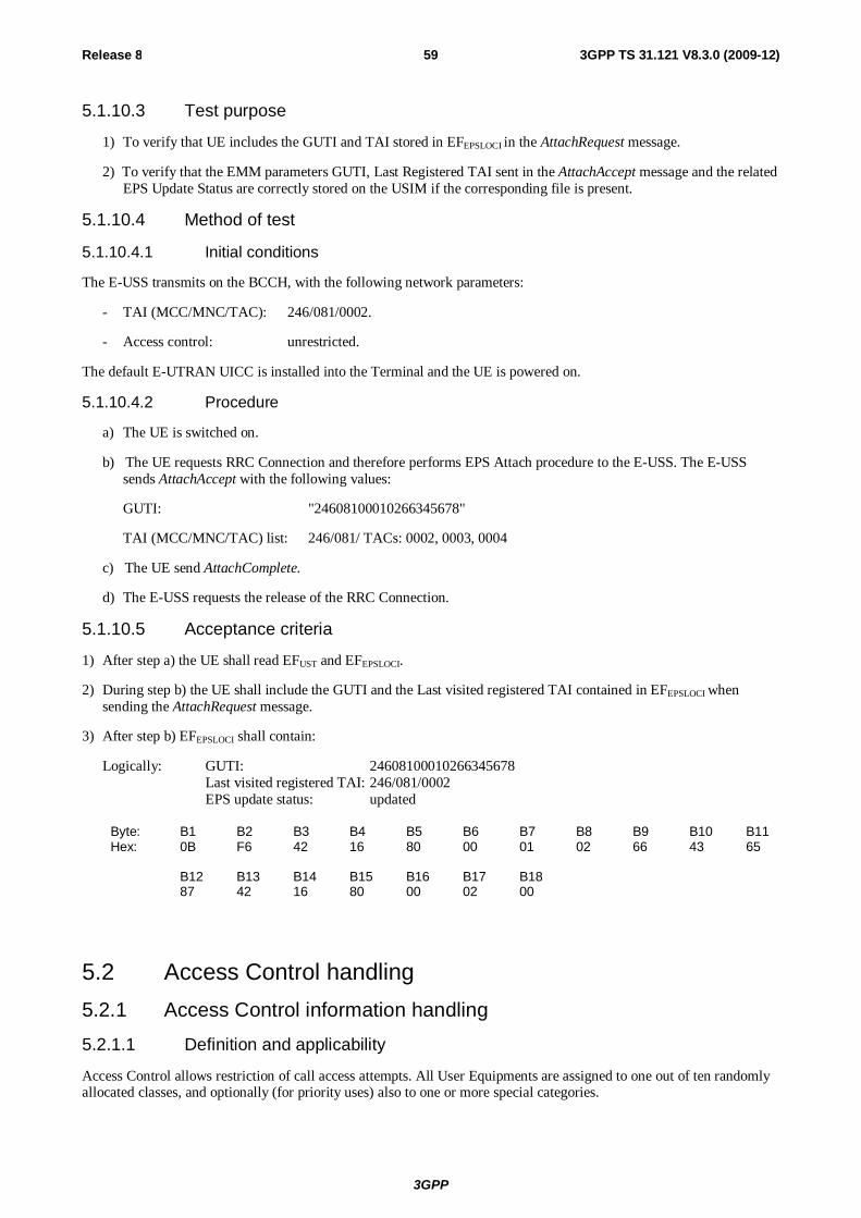
3GPP
Release 8 59 3GPP TS 31.121 V8.3.0 (2009-12)
5.1.10.3 Test purpose
1) To verify that UE includes the GUTI and TAI stored in EFEPSLOCI in the AttachRequest message.
2) To verify that the EMM parameters GUTI, Last Registered TAI sent in the AttachAccept message and the related EPS Update Status are correctly stored on the USIM if the corresponding file is present.
5.1.10.4 Method of test
5.1.10.4.1 Initial conditions
The E-USS transmits on the BCCH, with the following network parameters:
- TAI (MCC/MNC/TAC): 246/081/0002.
- Access control: unrestricted.
The default E-UTRAN UICC is installed into the Terminal and the UE is powered on.
5.1.10.4.2 Procedure
a) The UE is switched on.
b) The UE requests RRC Connection and therefore performs EPS Attach procedure to the E-USS. The E-USS sends AttachAccept with the following values:
GUTI: "24608100010266345678"
TAI (MCC/MNC/TAC) list: 246/081/ TACs: 0002, 0003, 0004
c) The UE send AttachComplete.
d) The E-USS requests the release of the RRC Connection.
5.1.10.5 Acceptance criteria
1) After step a) the UE shall read EFUST and EFEPSLOCI.
2) During step b) the UE shall include the GUTI and the Last visited registered TAI contained in EFEPSLOCI when sending the AttachRequest message.
3) After step b) EFEPSLOCI shall contain:
Logically: GUTI: 24608100010266345678 Last visited registered TAI: 246/081/0002 EPS update status: updated
Byte: B1 B2 B3 B4 B5 B6 B7 B8 B9 B10 B11 Hex: 0B F6 42 16 80 00 01 02 66 43 65 B12 B13 B14 B15 B16 B17 B18 87 42 16 80 00 02 00
5.2 Access Control handling 5.2.1 Access Control information handling
5.2.1.1 Definition and applicability
Access Control allows restriction of call access attempts. All User Equipments are assigned to one out of ten randomly allocated classes, and optionally (for priority uses) also to one or more special categories.
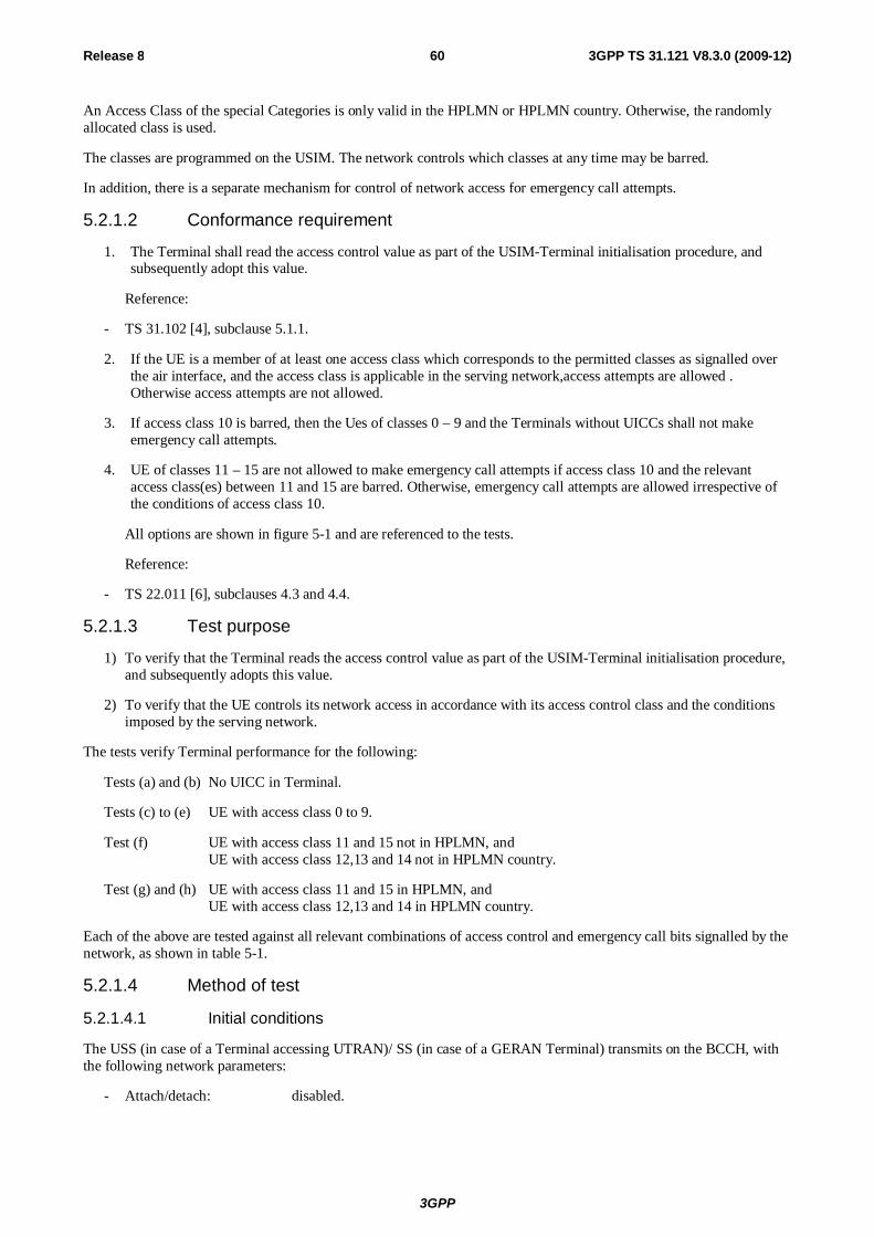
3GPP
Release 8 60 3GPP TS 31.121 V8.3.0 (2009-12)
An Access Class of the special Categories is only valid in the HPLMN or HPLMN country. Otherwise, the randomly allocated class is used.
The classes are programmed on the USIM. The network controls which classes at any time may be barred.
In addition, there is a separate mechanism for control of network access for emergency call attempts.
5.2.1.2 Conformance requirement
1. The Terminal shall read the access control value as part of the USIM-Terminal initialisation procedure, and subsequently adopt this value.
Reference:
- TS 31.102 [4], subclause 5.1.1.
2. If the UE is a member of at least one access class which corresponds to the permitted classes as signalled over the air interface, and the access class is applicable in the serving network,access attempts are allowed . Otherwise access attempts are not allowed.
3. If access class 10 is barred, then the Ues of classes 0 – 9 and the Terminals without UICCs shall not make emergency call attempts.
4. UE of classes 11 – 15 are not allowed to make emergency call attempts if access class 10 and the relevant access class(es) between 11 and 15 are barred. Otherwise, emergency call attempts are allowed irrespective of the conditions of access class 10.
All options are shown in figure 5-1 and are referenced to the tests.
Reference:
- TS 22.011 [6], subclauses 4.3 and 4.4.
5.2.1.3 Test purpose
1) To verify that the Terminal reads the access control value as part of the USIM-Terminal initialisation procedure, and subsequently adopts this value.
2) To verify that the UE controls its network access in accordance with its access control class and the conditions imposed by the serving network.
The tests verify Terminal performance for the following:
Tests (a) and (b) No UICC in Terminal.
Tests (c) to (e) UE with access class 0 to 9.
Test (f) UE with access class 11 and 15 not in HPLMN, and UE with access class 12,13 and 14 not in HPLMN country.
Test (g) and (h) UE with access class 11 and 15 in HPLMN, and UE with access class 12,13 and 14 in HPLMN country.
Each of the above are tested against all relevant combinations of access control and emergency call bits signalled by the network, as shown in table 5-1.
5.2.1.4 Method of test
5.2.1.4.1 Initial conditions
The USS (in case of a Terminal accessing UTRAN)/ SS (in case of a GERAN Terminal) transmits on the BCCH, with the following network parameters:
- Attach/detach: disabled.
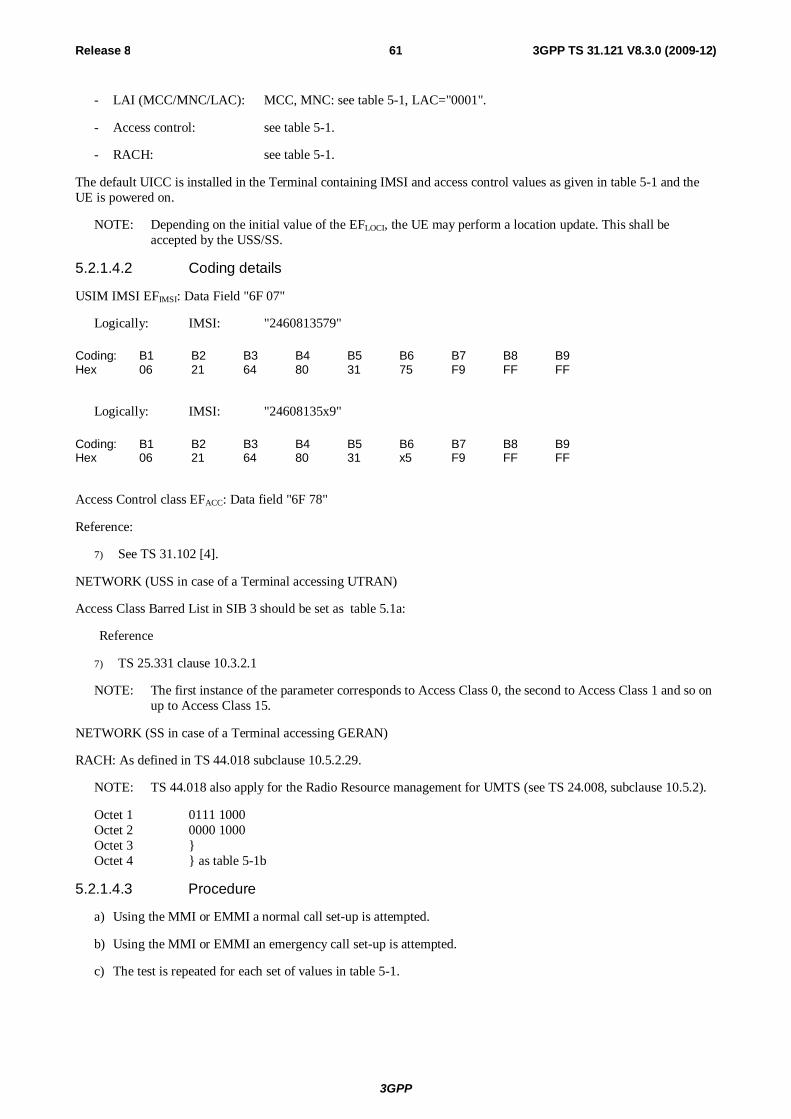
3GPP
Release 8 61 3GPP TS 31.121 V8.3.0 (2009-12)
- LAI (MCC/MNC/LAC): MCC, MNC: see table 5-1, LAC="0001".
- Access control: see table 5-1.
- RACH: see table 5-1.
The default UICC is installed in the Terminal containing IMSI and access control values as given in table 5-1 and the UE is powered on.
NOTE: Depending on the initial value of the EFLOCI, the UE may perform a location update. This shall be accepted by the USS/SS.
5.2.1.4.2 Coding details
USIM IMSI EFIMSI: Data Field "6F 07"
Logically: IMSI: "2460813579"
Coding: B1 B2 B3 B4 B5 B6 B7 B8 B9 Hex 06 21 64 80 31 75 F9 FF FF
Logically: IMSI: "24608135x9"
Coding: B1 B2 B3 B4 B5 B6 B7 B8 B9 Hex 06 21 64 80 31 x5 F9 FF FF
Access Control class EFACC: Data field "6F 78"
Reference:
7) See TS 31.102 [4].
NETWORK (USS in case of a Terminal accessing UTRAN)
Access Class Barred List in SIB 3 should be set as table 5.1a:
Reference
7) TS 25.331 clause 10.3.2.1
NOTE: The first instance of the parameter corresponds to Access Class 0, the second to Access Class 1 and so on up to Access Class 15.
NETWORK (SS in case of a Terminal accessing GERAN)
RACH: As defined in TS 44.018 subclause 10.5.2.29.
NOTE: TS 44.018 also apply for the Radio Resource management for UMTS (see TS 24.008, subclause 10.5.2).
Octet 1 0111 1000 Octet 2 0000 1000 Octet 3 } Octet 4 } as table 5-1b
5.2.1.4.3 Procedure
a) Using the MMI or EMMI a normal call set-up is attempted.
b) Using the MMI or EMMI an emergency call set-up is attempted.
c) The test is repeated for each set of values in table 5-1.
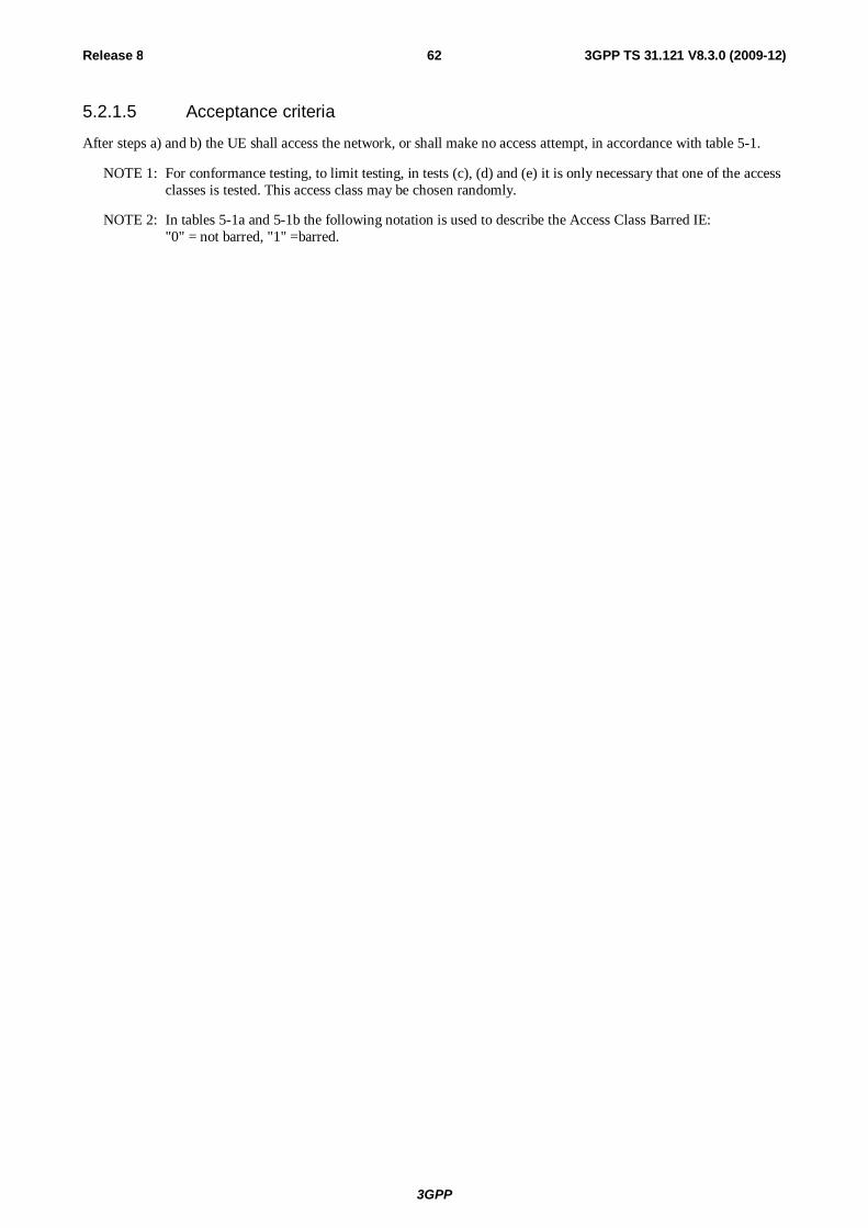
3GPP
Release 8 62 3GPP TS 31.121 V8.3.0 (2009-12)
5.2.1.5 Acceptance criteria
After steps a) and b) the UE shall access the network, or shall make no access attempt, in accordance with table 5-1.
NOTE 1: For conformance testing, to limit testing, in tests (c), (d) and (e) it is only necessary that one of the access classes is tested. This access class may be chosen randomly.
NOTE 2: In tables 5-1a and 5-1b the following notation is used to describe the Access Class Barred IE: "0" = not barred, "1" =barred.
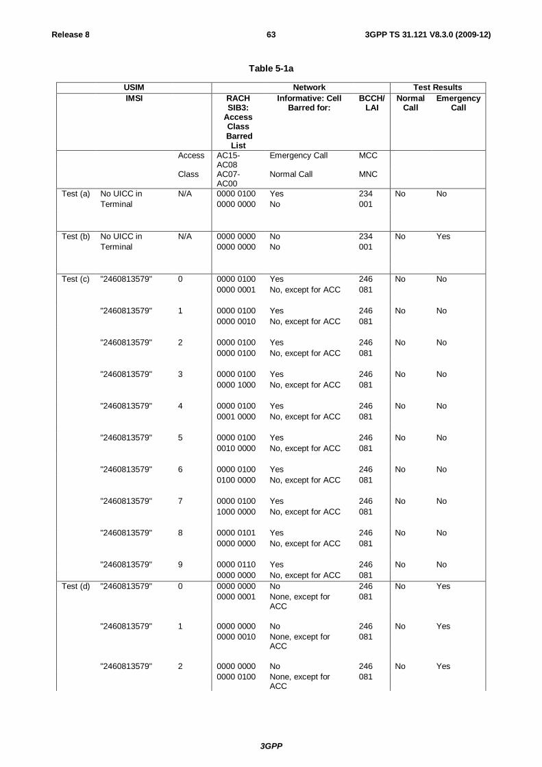
3GPP
Release 8 63 3GPP TS 31.121 V8.3.0 (2009-12)
Table 5-1a
USIM Network Test Results IMSI RACH
SIB3: Access Class
Barred List
Informative: Cell Barred for:
BCCH/LAI
Normal Call
Emergency Call
Access AC15-AC08
Emergency Call MCC
Class AC07-AC00
Normal Call MNC
Test (a) No UICC in N/A 0000 0100 Yes 234 No No Terminal 0000 0000 No 001 Test (b) No UICC in N/A 0000 0000 No 234 No Yes Terminal 0000 0000 No 001 Test (c) "2460813579" 0 0000 0100 Yes 246 No No 0000 0001 No, except for ACC 081 "2460813579" 1 0000 0100 Yes 246 No No 0000 0010 No, except for ACC 081 "2460813579" 2 0000 0100 Yes 246 No No 0000 0100 No, except for ACC 081 "2460813579" 3 0000 0100 Yes 246 No No 0000 1000 No, except for ACC 081 "2460813579" 4 0000 0100 Yes 246 No No 0001 0000 No, except for ACC 081 "2460813579" 5 0000 0100 Yes 246 No No 0010 0000 No, except for ACC 081 "2460813579" 6 0000 0100 Yes 246 No No 0100 0000 No, except for ACC 081 "2460813579" 7 0000 0100 Yes 246 No No 1000 0000 No, except for ACC 081 "2460813579" 8 0000 0101 Yes 246 No No 0000 0000 No, except for ACC 081 "2460813579" 9 0000 0110 Yes 246 No No 0000 0000 No, except for ACC 081 Test (d) "2460813579" 0 0000 0000 No 246 No Yes 0000 0001 None, except for
ACC 081
"2460813579" 1 0000 0000 No 246 No Yes 0000 0010 None, except for
ACC 081
"2460813579" 2 0000 0000 No 246 No Yes 0000 0100 None, except for
ACC 081
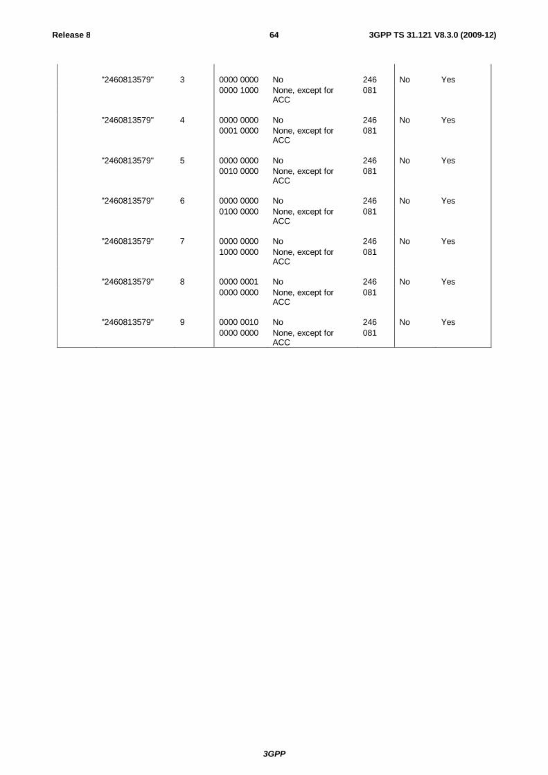
3GPP
Release 8 64 3GPP TS 31.121 V8.3.0 (2009-12)
"2460813579" 3 0000 0000 No 246 No Yes 0000 1000 None, except for
ACC 081
"2460813579" 4 0000 0000 No 246 No Yes 0001 0000 None, except for
ACC 081
"2460813579" 5 0000 0000 No 246 No Yes 0010 0000 None, except for
ACC 081
"2460813579" 6 0000 0000 No 246 No Yes 0100 0000 None, except for
ACC 081
"2460813579" 7 0000 0000 No 246 No Yes 1000 0000 None, except for
ACC 081
"2460813579" 8 0000 0001 No 246 No Yes 0000 0000 None, except for
ACC 081
"2460813579" 9 0000 0010 No 246 No Yes 0000 0000 None, except for
ACC 081

3GPP
Release 8 65 3GPP TS 31.121 V8.3.0 (2009-12)
Test (e) "2460813579" 0 1111 1011 No 246 Yes Yes 1111 1110 All, except ACC on
USIM 081
"2460813579" 1 1111 1011 No 246 Yes Yes 1111 1101 All, except ACC on
USIM 081
"2460813579" 2 1111 1011 No 246 Yes Yes 1111 1011 All, except ACC on
USIM 081
"2460813579" 3 1111 1011 No 246 Yes Yes 1111 0111 All, except ACC on
USIM 081
"2460813579" 4 1111 1011 No 246 Yes Yes 1110 1111 All, except ACC on
USIM 081
"2460813579" 5 1111 1011 No 246 Yes Yes 1101 1111 All, except ACC on
USIM 081
"2460813579" 6 1111 1011 No 246 Yes Yes 1011 1111 All, except ACC on
USIM 081
"2406813579" 7 1111 1011 No 246 Yes Yes 0111 1111 All, except ACC on
USIM 081
"2460813579" 8 1111 1010 No 246 Yes Yes 1111 1111 All, except ACC on
USIM 081
"2460813579" 9 1111 1001 No 246 Yes Yes 1111 1111 All, except ACC on
USIM 081
Test (f) "24608135x9" 11 & x 0000 0111 Yes 246 No No 1111 1111 All, except ACC
greater than 11 082
" 11 & x 0000 0011 No 246 No Yes 1111 1111 All, except ACC
greater than 11 082
" 11 & x 0000 0000 No 246 Yes Yes 0000 0000 None 082 "24608135x9" 12 & x 0000 0111 Yes 244 No No 1111 1111 All, except ACC
greater than 11 001
" 12 & x 0000 0011 No 244 No Yes 1111 1111 All, except ACC
greater than 11 001
" 12 & x 0000 0000 No 244 Yes Yes 0000 0000 None 001 "24608135x9" 13 & x 0000 0111 Yes 244 No No 1111 1111 All, except ACC
greater than 11 001
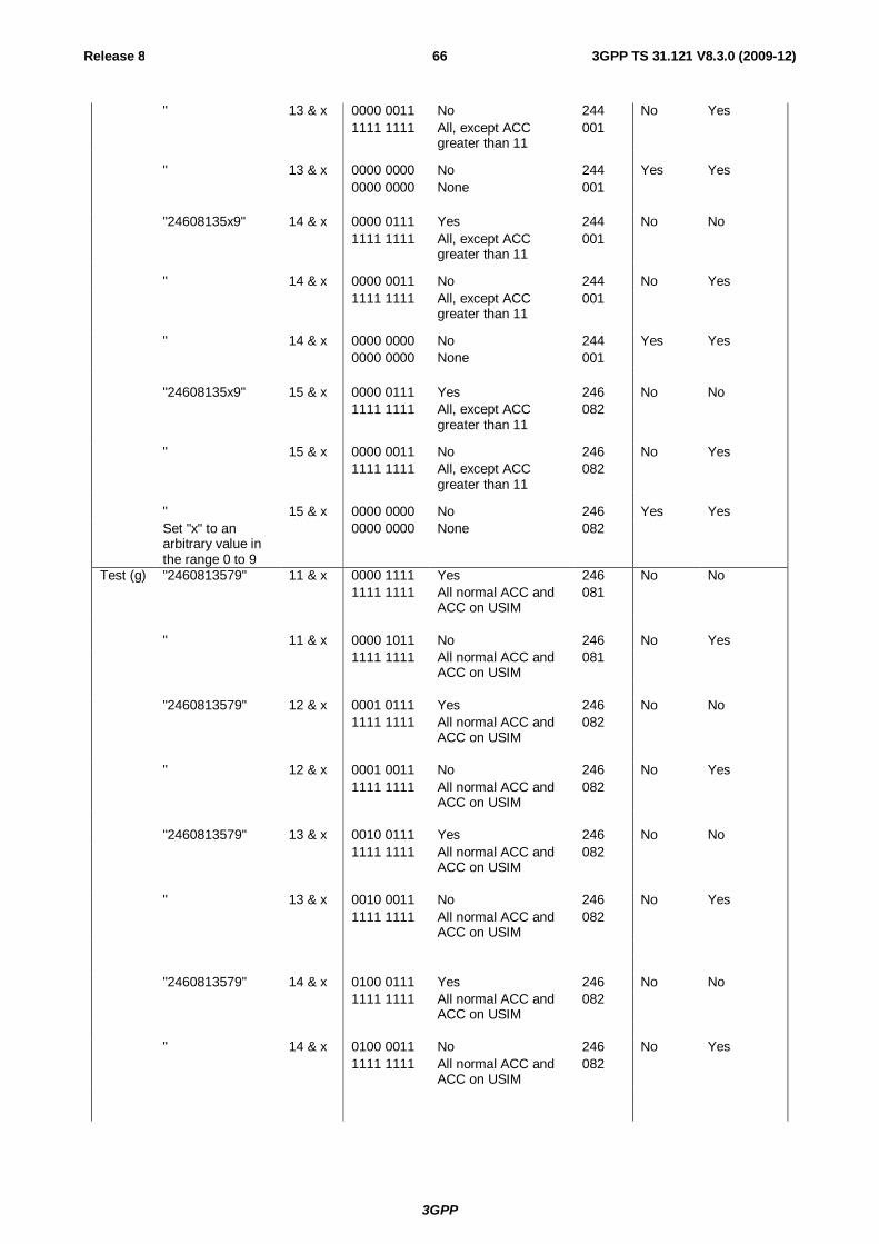
3GPP
Release 8 66 3GPP TS 31.121 V8.3.0 (2009-12)
" 13 & x 0000 0011 No 244 No Yes 1111 1111 All, except ACC
greater than 11 001
" 13 & x 0000 0000 No 244 Yes Yes 0000 0000 None 001 "24608135x9" 14 & x 0000 0111 Yes 244 No No 1111 1111 All, except ACC
greater than 11 001
" 14 & x 0000 0011 No 244 No Yes 1111 1111 All, except ACC
greater than 11 001
" 14 & x 0000 0000 No 244 Yes Yes 0000 0000 None 001 "24608135x9" 15 & x 0000 0111 Yes 246 No No 1111 1111 All, except ACC
greater than 11 082
" 15 & x 0000 0011 No 246 No Yes 1111 1111 All, except ACC
greater than 11 082
" 15 & x 0000 0000 No 246 Yes Yes Set "x" to an
arbitrary value in the range 0 to 9
0000 0000 None 082
Test (g) "2460813579" 11 & x 0000 1111 Yes 246 No No 1111 1111 All normal ACC and
ACC on USIM 081
" 11 & x 0000 1011 No 246 No Yes 1111 1111 All normal ACC and
ACC on USIM 081
"2460813579" 12 & x 0001 0111 Yes 246 No No 1111 1111 All normal ACC and
ACC on USIM 082
" 12 & x 0001 0011 No 246 No Yes 1111 1111 All normal ACC and
ACC on USIM 082
"2460813579" 13 & x 0010 0111 Yes 246 No No 1111 1111 All normal ACC and
ACC on USIM 082
" 13 & x 0010 0011 No 246 No Yes 1111 1111 All normal ACC and
ACC on USIM 082
"2460813579" 14 & x 0100 0111 Yes 246 No No 1111 1111 All normal ACC and
ACC on USIM 082
" 14 & x 0100 0011 No 246 No Yes 1111 1111 All normal ACC and
ACC on USIM 082
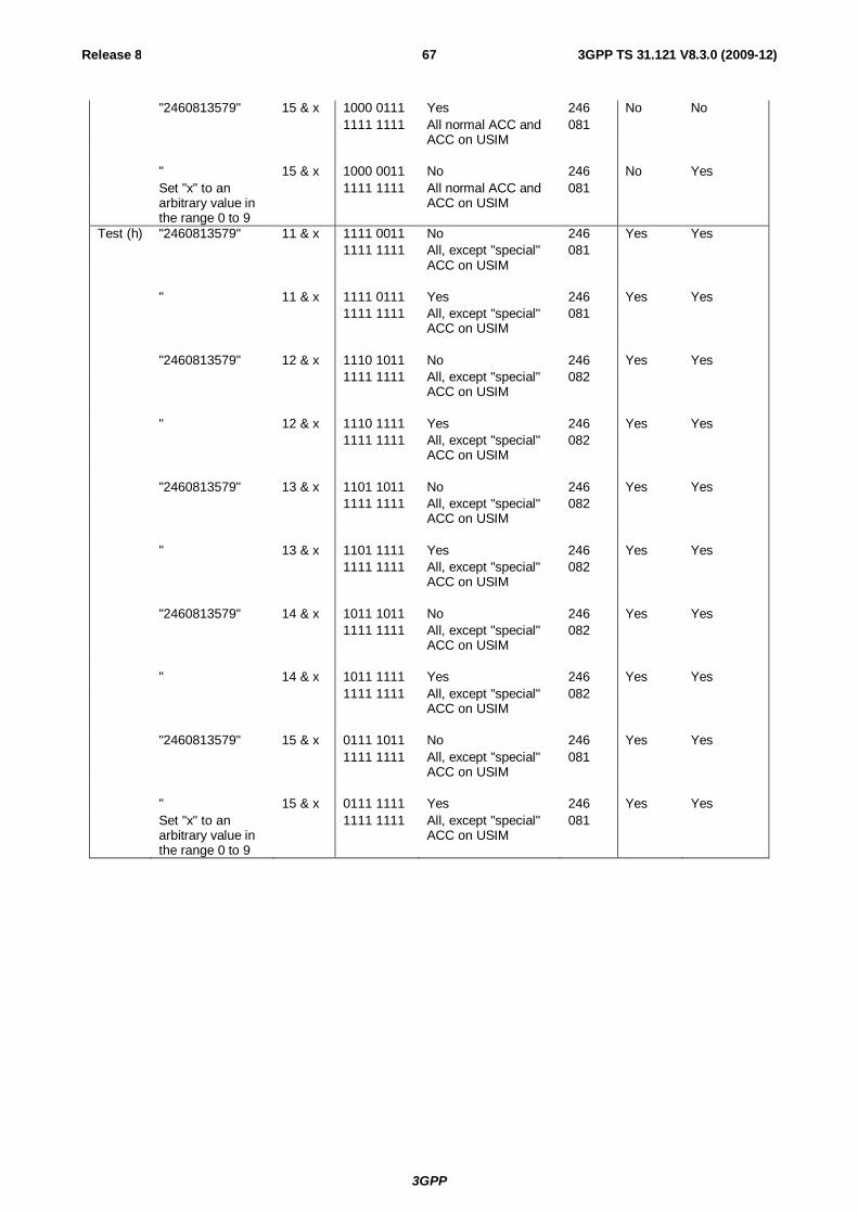
3GPP
Release 8 67 3GPP TS 31.121 V8.3.0 (2009-12)
"2460813579" 15 & x 1000 0111 Yes 246 No No 1111 1111 All normal ACC and
ACC on USIM 081
" 15 & x 1000 0011 No 246 No Yes Set "x" to an
arbitrary value in the range 0 to 9
1111 1111 All normal ACC and ACC on USIM
081
Test (h) "2460813579" 11 & x 1111 0011 No 246 Yes Yes 1111 1111 All, except "special"
ACC on USIM 081
" 11 & x 1111 0111 Yes 246 Yes Yes 1111 1111 All, except "special"
ACC on USIM 081
"2460813579" 12 & x 1110 1011 No 246 Yes Yes 1111 1111 All, except "special"
ACC on USIM 082
" 12 & x 1110 1111 Yes 246 Yes Yes 1111 1111 All, except "special"
ACC on USIM 082
"2460813579" 13 & x 1101 1011 No 246 Yes Yes 1111 1111 All, except "special"
ACC on USIM 082
" 13 & x 1101 1111 Yes 246 Yes Yes 1111 1111 All, except "special"
ACC on USIM 082
"2460813579" 14 & x 1011 1011 No 246 Yes Yes 1111 1111 All, except "special"
ACC on USIM 082
" 14 & x 1011 1111 Yes 246 Yes Yes 1111 1111 All, except "special"
ACC on USIM 082
"2460813579" 15 & x 0111 1011 No 246 Yes Yes 1111 1111 All, except "special"
ACC on USIM 081
" 15 & x 0111 1111 Yes 246 Yes Yes Set "x" to an
arbitrary value in the range 0 to 9
1111 1111 All, except "special" ACC on USIM
081
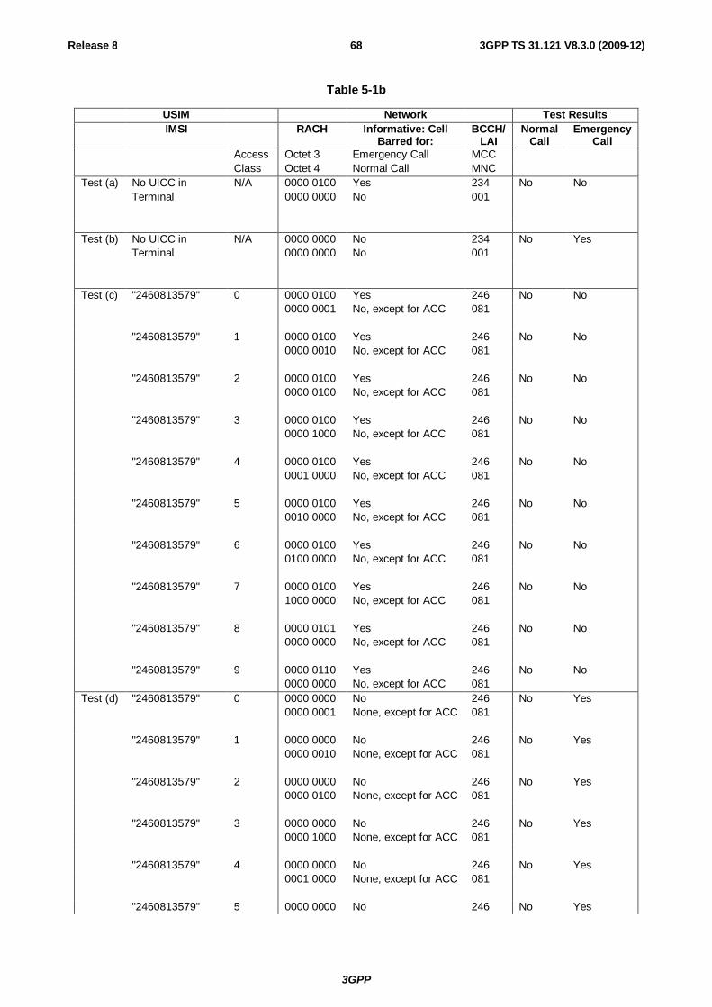
3GPP
Release 8 68 3GPP TS 31.121 V8.3.0 (2009-12)
Table 5-1b
USIM Network Test Results IMSI RACH Informative: Cell
Barred for: BCCH/
LAI Normal
Call Emergency
Call Access Octet 3 Emergency Call MCC Class Octet 4 Normal Call MNC Test (a) No UICC in N/A 0000 0100 Yes 234 No No Terminal 0000 0000 No 001 Test (b) No UICC in N/A 0000 0000 No 234 No Yes Terminal 0000 0000 No 001 Test (c) "2460813579" 0 0000 0100 Yes 246 No No 0000 0001 No, except for ACC 081 "2460813579" 1 0000 0100 Yes 246 No No 0000 0010 No, except for ACC 081 "2460813579" 2 0000 0100 Yes 246 No No 0000 0100 No, except for ACC 081 "2460813579" 3 0000 0100 Yes 246 No No 0000 1000 No, except for ACC 081 "2460813579" 4 0000 0100 Yes 246 No No 0001 0000 No, except for ACC 081 "2460813579" 5 0000 0100 Yes 246 No No 0010 0000 No, except for ACC 081 "2460813579" 6 0000 0100 Yes 246 No No 0100 0000 No, except for ACC 081 "2460813579" 7 0000 0100 Yes 246 No No 1000 0000 No, except for ACC 081 "2460813579" 8 0000 0101 Yes 246 No No 0000 0000 No, except for ACC 081 "2460813579" 9 0000 0110 Yes 246 No No 0000 0000 No, except for ACC 081 Test (d) "2460813579" 0 0000 0000 No 246 No Yes 0000 0001 None, except for ACC 081 "2460813579" 1 0000 0000 No 246 No Yes 0000 0010 None, except for ACC 081 "2460813579" 2 0000 0000 No 246 No Yes 0000 0100 None, except for ACC 081 "2460813579" 3 0000 0000 No 246 No Yes 0000 1000 None, except for ACC 081 "2460813579" 4 0000 0000 No 246 No Yes 0001 0000 None, except for ACC 081 "2460813579" 5 0000 0000 No 246 No Yes
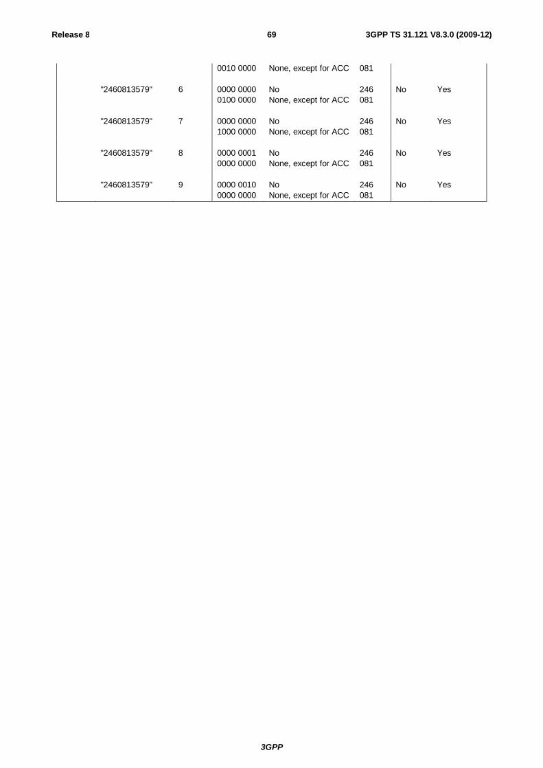
3GPP
Release 8 69 3GPP TS 31.121 V8.3.0 (2009-12)
0010 0000 None, except for ACC 081 "2460813579" 6 0000 0000 No 246 No Yes 0100 0000 None, except for ACC 081 "2460813579" 7 0000 0000 No 246 No Yes 1000 0000 None, except for ACC 081 "2460813579" 8 0000 0001 No 246 No Yes 0000 0000 None, except for ACC 081 "2460813579" 9 0000 0010 No 246 No Yes 0000 0000 None, except for ACC 081
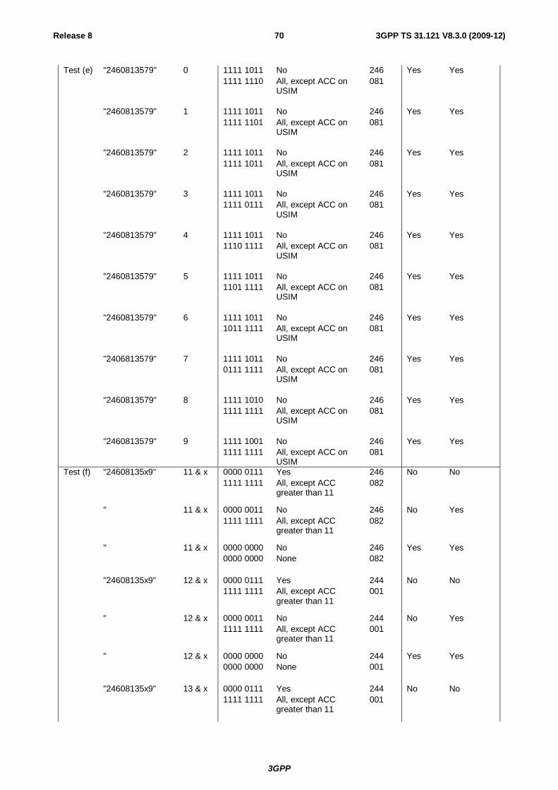
3GPP
Release 8 70 3GPP TS 31.121 V8.3.0 (2009-12)
Test (e) "2460813579" 0 1111 1011 No 246 Yes Yes 1111 1110 All, except ACC on
USIM 081
"2460813579" 1 1111 1011 No 246 Yes Yes 1111 1101 All, except ACC on
USIM 081
"2460813579" 2 1111 1011 No 246 Yes Yes 1111 1011 All, except ACC on
USIM 081
"2460813579" 3 1111 1011 No 246 Yes Yes 1111 0111 All, except ACC on
USIM 081
"2460813579" 4 1111 1011 No 246 Yes Yes 1110 1111 All, except ACC on
USIM 081
"2460813579" 5 1111 1011 No 246 Yes Yes 1101 1111 All, except ACC on
USIM 081
"2460813579" 6 1111 1011 No 246 Yes Yes 1011 1111 All, except ACC on
USIM 081
"2406813579" 7 1111 1011 No 246 Yes Yes 0111 1111 All, except ACC on
USIM 081
"2460813579" 8 1111 1010 No 246 Yes Yes 1111 1111 All, except ACC on
USIM 081
"2460813579" 9 1111 1001 No 246 Yes Yes 1111 1111 All, except ACC on
USIM 081
Test (f) "24608135x9" 11 & x 0000 0111 Yes 246 No No 1111 1111 All, except ACC
greater than 11 082
" 11 & x 0000 0011 No 246 No Yes 1111 1111 All, except ACC
greater than 11 082
" 11 & x 0000 0000 No 246 Yes Yes 0000 0000 None 082 "24608135x9" 12 & x 0000 0111 Yes 244 No No 1111 1111 All, except ACC
greater than 11 001
" 12 & x 0000 0011 No 244 No Yes 1111 1111 All, except ACC
greater than 11 001
" 12 & x 0000 0000 No 244 Yes Yes 0000 0000 None 001 "24608135x9" 13 & x 0000 0111 Yes 244 No No 1111 1111 All, except ACC
greater than 11 001
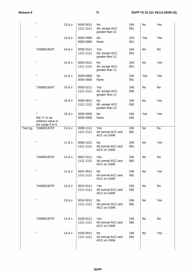
3GPP
Release 8 71 3GPP TS 31.121 V8.3.0 (2009-12)
" 13 & x 0000 0011 No 244 No Yes 1111 1111 All, except ACC
greater than 11 001
" 13 & x 0000 0000 No 244 Yes Yes 0000 0000 None 001 "24608135x9" 14 & x 0000 0111 Yes 244 No No 1111 1111 All, except ACC
greater than 11 001
" 14 & x 0000 0011 No 244 No Yes 1111 1111 All, except ACC
greater than 11 001
" 14 & x 0000 0000 No 244 Yes Yes 0000 0000 None 001 "24608135x9" 15 & x 0000 0111 Yes 246 No No 1111 1111 All, except ACC
greater than 11 082
" 15 & x 0000 0011 No 246 No Yes 1111 1111 All, except ACC
greater than 11 082
" 15 & x 0000 0000 No 246 Yes Yes Set "x" to an
arbitrary value in the range 0 to 9
0000 0000 None 082
Test (g) "2460813579" 11 & x 0000 1111 Yes 246 No No 1111 1111 All normal ACC and
ACC on USIM 081
" 11 & x 0000 1011 No 246 No Yes 1111 1111 All normal ACC and
ACC on USIM 081
"2460813579" 12 & x 0001 0111 Yes 246 No No 1111 1111 All normal ACC and
ACC on USIM 082
" 12 & x 0001 0011 No 246 No Yes 1111 1111 All normal ACC and
ACC on USIM 082
"2460813579" 13 & x 0010 0111 Yes 246 No No 1111 1111 All normal ACC and
ACC on USIM 082
" 13 & x 0010 0011 No 246 No Yes 1111 1111 All normal ACC and
ACC on USIM 082
"2460813579" 14 & x 0100 0111 Yes 246 No No 1111 1111 All normal ACC and
ACC on USIM 082
" 14 & x 0100 0011 No 246 No Yes 1111 1111 All normal ACC and
ACC on USIM 082
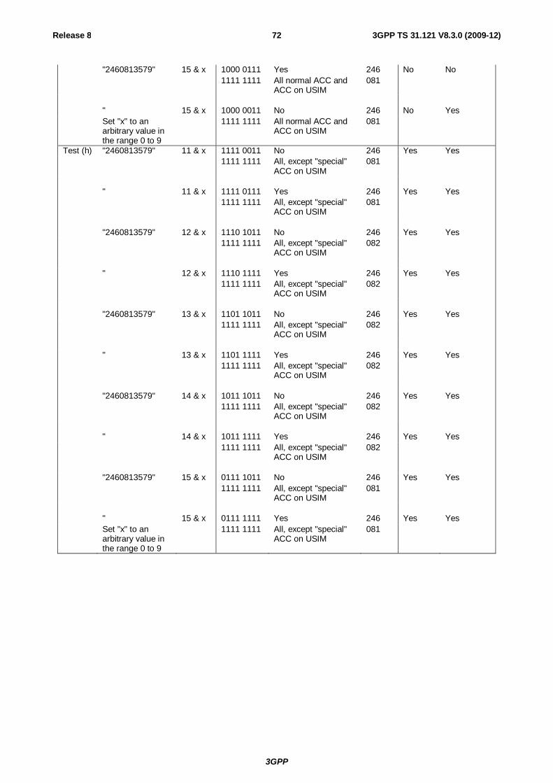
3GPP
Release 8 72 3GPP TS 31.121 V8.3.0 (2009-12)
"2460813579" 15 & x 1000 0111 Yes 246 No No 1111 1111 All normal ACC and
ACC on USIM 081
" 15 & x 1000 0011 No 246 No Yes Set "x" to an
arbitrary value in the range 0 to 9
1111 1111 All normal ACC and ACC on USIM
081
Test (h) "2460813579" 11 & x 1111 0011 No 246 Yes Yes 1111 1111 All, except "special"
ACC on USIM 081
" 11 & x 1111 0111 Yes 246 Yes Yes 1111 1111 All, except "special"
ACC on USIM 081
"2460813579" 12 & x 1110 1011 No 246 Yes Yes 1111 1111 All, except "special"
ACC on USIM 082
" 12 & x 1110 1111 Yes 246 Yes Yes 1111 1111 All, except "special"
ACC on USIM 082
"2460813579" 13 & x 1101 1011 No 246 Yes Yes 1111 1111 All, except "special"
ACC on USIM 082
" 13 & x 1101 1111 Yes 246 Yes Yes 1111 1111 All, except "special"
ACC on USIM 082
"2460813579" 14 & x 1011 1011 No 246 Yes Yes 1111 1111 All, except "special"
ACC on USIM 082
" 14 & x 1011 1111 Yes 246 Yes Yes 1111 1111 All, except "special"
ACC on USIM 082
"2460813579" 15 & x 0111 1011 No 246 Yes Yes 1111 1111 All, except "special"
ACC on USIM 081
" 15 & x 0111 1111 Yes 246 Yes Yes Set "x" to an
arbitrary value in the range 0 to 9
1111 1111 All, except "special" ACC on USIM
081
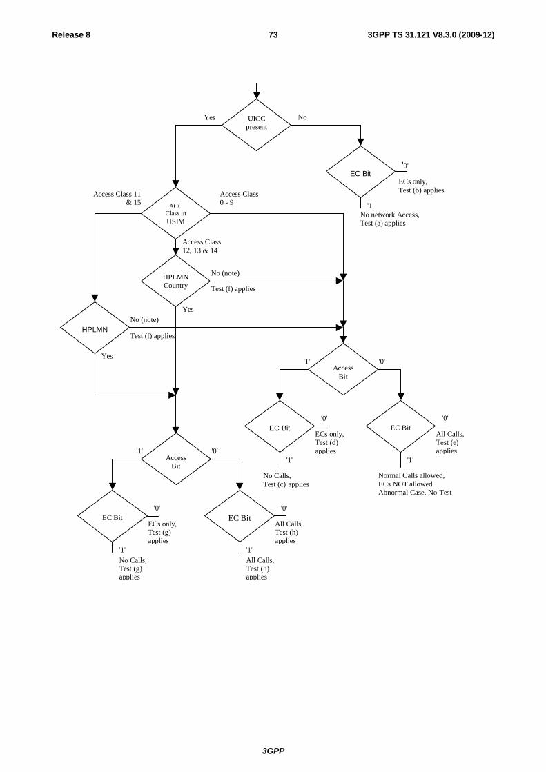
3GPP
Release 8 73 3GPP TS 31.121 V8.3.0 (2009-12)
ECs only, Test (b) applies
No (note)
Yes
EC Bit
ACC Class in USIM
UICC present
Yes No
HPLMN
HPLMN Country
Access Bit
'1'
'0'
'1' '0'
Access Bit
'1' '0'
No (note)
Yes
Access Class 0 - 9
Access Class 11 & 15
Access Class 12, 13 & 14
No network Access, Test (a) applies
Test (f) applies
Test (f) applies
EC Bit
'1'
'0'
All Calls, Test (h) applies
All Calls, Test (h) applies
EC Bit
'1'
'0'
ECs only, Test (d) applies
No Calls, Test (c) applies
EC Bit
'1'
'0'
ECs only, Test (g) applies
No Calls, Test (g) applies
EC Bit
'1'
'0'
All Calls, Test (e) applies
Normal Calls allowed, ECs NOT allowed Abnormal Case, No Test
3GPP
Release 8 74 3GPP TS 31.121 V8.3.0 (2009-12)
NOTE: UE adopts Access Class 0-9, based on IMSI, see TS 22.011 [6]. Access Class in USIM, See TS 31.102 [4], EF ACC, "6F 78". Ecs: Emergency Calls. EC Bit: In case of GERAN:
Bit 3 of Octet 3 of RACH Control Parameters, See TS 44.018 Section 10.5.2.29. In case of UTRAN Access Class 10 defined in TS 22.011 clause 4.4.
AC Bit: See Access Class Barred List defined in TS 25.331 clause 10.3.2.1. HPLMN: Country means that the MCC of the VPLMN is the same as the MCC of the HPLMN.
Figure 5-1: Access control information
5.2.2 Access Control information handling for E-UTRAN/EPC 5.2.2.1 Definition and applicability
Access Control allows restriction of EPS bearer context activation access attempts. All User Equipments are assigned to one out of ten randomly allocated classes, and optionally (for priority uses) also to one or more special categories.
An Access Class of the special categories is only valid in the HPLMN or HPLMN country. Otherwise, the randomly allocated class is used.
The classes are programmed on the USIM. The network controls which classes at any time may be barred.
Emergency call handling is FFS.
5.2.2.2 Conformance requirement
1. The Terminal shall read the access control value as part of the USIM-Terminal initialisation procedure, and subsequently adopt this value.
Reference:
- TS 31.102 [4], subclause 5.1.1.
2. If the UE is a member of at least one access class which corresponds to the permitted classes as signalled over the air interface, and the access class is applicable in the serving network,access attempts are allowed . Otherwise access attempts are not allowed.
All options are shown in figure 5-2 and are referenced to the tests.
Reference:
- TS 22.011 [6], subclauses 4.3 and 4.4,
- TS 24.301 [26], subclause 5.5.1.2.6,
5.2.2.3 Test purpose
1) To verify that the Terminal reads the access control value as part of the USIM-Terminal initialisation procedure, and subsequently adopts this value.
2) To verify that the UE controls its network access in accordance with its access control class and the conditions imposed by the serving network.
The tests verify Terminal performance for the following:
Tests (a) and (b) No UICC in Terminal.
Tests (c) to (e) UE with access class 0 to 9.
Test (f) UE with access class 11 and 15 not in HPLMN, and UE with access class 12,13 and 14 not in HPLMN country.
Test (g) and (h) UE with access class 11 and 15 in HPLMN, and
3GPP
Release 8 75 3GPP TS 31.121 V8.3.0 (2009-12)
UE with access class 12,13 and 14 in HPLMN country.
Each of the above are tested against all relevant combinations of access control bits signalled by the network, as shown in table 5-1.
5.2.2.4 Method of test
5.2.2.4.1 Initial conditions
The E-USS transmits on the BCCH, with the following network parameters:
- Attach/detach: disabled.
- TAI (MCC/MNC/TAC): MCC, MNC: see table 5-2, TAC="0001".
- Access control: see table 5-2.
- RACH: see table 5-2.
The default UICC is installed in the Terminal containing IMSI and access control values as given in table 5-x and the UE is powered on.
NOTE: Depending on the initial value of the EFEPSLOCI, the UE may perform a location update. This shall be accepted by the E-USS.
5.2.2.4.2 Coding details
EFIMSI: Data Field "6F 07"
Logically: IMSI: "2460813579"
Coding: B1 B2 B3 B4 B5 B6 B7 B8 B9 Hex 06 21 64 80 31 75 F9 FF FF
Logically: IMSI: "24608135x9"
Coding: B1 B2 B3 B4 B5 B6 B7 B8 B9 Hex 06 21 64 80 31 x5 F9 FF FF
Access Control class EFACC: Data field "6F 78"
Reference:
See TS 31.102 [4].
NETWORK (E-USS)
Access Class Barred List in SIB 3 should be set as table 5.2:
Reference
TS 25.331 clause 10.3.2.1
NOTE: The first instance of the parameter corresponds to Access Class 0, the second to Access Class 1 and so on up to Access Class 15.
5.2.2.4.3 Procedure
a) Using the MMI or EMMI a normal EPS bearer context setup is attempted.
b) The test is repeated for each set of values in table 5-2.

3GPP
Release 8 76 3GPP TS 31.121 V8.3.0 (2009-12)
5.2.2.5 Acceptance criteria
After step a) the UE shall access the network, or shall make no access attempt, in accordance with table 5-x.
NOTE 1: For conformance testing, to limit testing, in tests (c), (d) and (e) it is only necessary that one of the access classes is tested. This access class may be chosen randomly.
NOTE 2: In tables 5-2 the following notation is used to describe the Access Class Barred IE: "0" = not barred, "1" =barred.
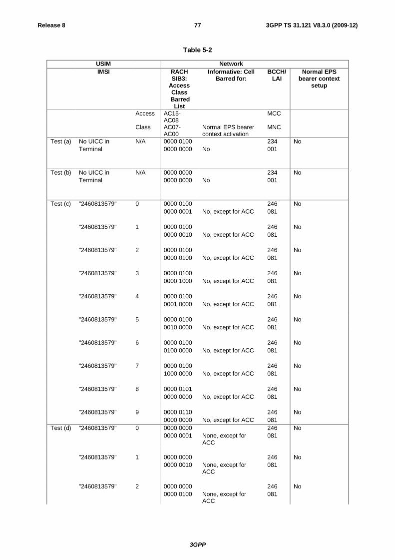
3GPP
Release 8 77 3GPP TS 31.121 V8.3.0 (2009-12)
Table 5-2
USIM Network IMSI RACH
SIB3: Access Class
Barred List
Informative: Cell Barred for:
BCCH/LAI
Normal EPS bearer context
setup
Access AC15-AC08
MCC
Class AC07-AC00
Normal EPS bearer context activation
MNC
Test (a) No UICC in N/A 0000 0100 234 No Terminal 0000 0000 No 001 Test (b) No UICC in N/A 0000 0000 234 No Terminal 0000 0000 No 001 Test (c) "2460813579" 0 0000 0100 246 No 0000 0001 No, except for ACC 081 "2460813579" 1 0000 0100 246 No 0000 0010 No, except for ACC 081 "2460813579" 2 0000 0100 246 No 0000 0100 No, except for ACC 081 "2460813579" 3 0000 0100 246 No 0000 1000 No, except for ACC 081 "2460813579" 4 0000 0100 246 No 0001 0000 No, except for ACC 081 "2460813579" 5 0000 0100 246 No 0010 0000 No, except for ACC 081 "2460813579" 6 0000 0100 246 No 0100 0000 No, except for ACC 081 "2460813579" 7 0000 0100 246 No 1000 0000 No, except for ACC 081 "2460813579" 8 0000 0101 246 No 0000 0000 No, except for ACC 081 "2460813579" 9 0000 0110 246 No 0000 0000 No, except for ACC 081 Test (d) "2460813579" 0 0000 0000 246 No 0000 0001 None, except for
ACC 081
"2460813579" 1 0000 0000 246 No 0000 0010 None, except for
ACC 081
"2460813579" 2 0000 0000 246 No 0000 0100 None, except for
ACC 081
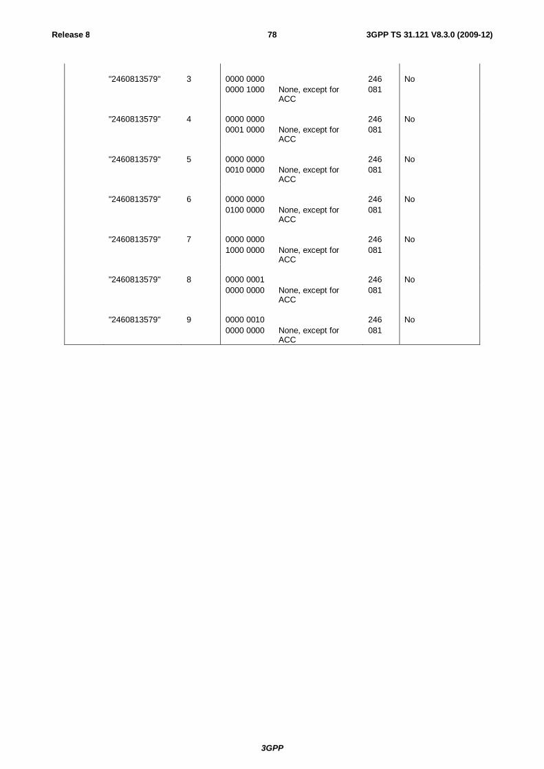
3GPP
Release 8 78 3GPP TS 31.121 V8.3.0 (2009-12)
"2460813579" 3 0000 0000 246 No 0000 1000 None, except for
ACC 081
"2460813579" 4 0000 0000 246 No 0001 0000 None, except for
ACC 081
"2460813579" 5 0000 0000 246 No 0010 0000 None, except for
ACC 081
"2460813579" 6 0000 0000 246 No 0100 0000 None, except for
ACC 081
"2460813579" 7 0000 0000 246 No 1000 0000 None, except for
ACC 081
"2460813579" 8 0000 0001 246 No 0000 0000 None, except for
ACC 081
"2460813579" 9 0000 0010 246 No 0000 0000 None, except for
ACC 081
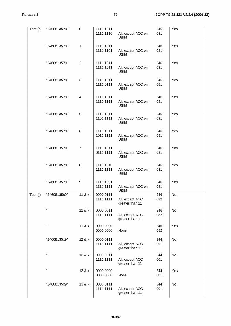
3GPP
Release 8 79 3GPP TS 31.121 V8.3.0 (2009-12)
Test (e) "2460813579" 0 1111 1011 246 Yes 1111 1110 All, except ACC on
USIM 081
"2460813579" 1 1111 1011 246 Yes 1111 1101 All, except ACC on
USIM 081
"2460813579" 2 1111 1011 246 Yes 1111 1011 All, except ACC on
USIM 081
"2460813579" 3 1111 1011 246 Yes 1111 0111 All, except ACC on
USIM 081
"2460813579" 4 1111 1011 246 Yes 1110 1111 All, except ACC on
USIM 081
"2460813579" 5 1111 1011 246 Yes 1101 1111 All, except ACC on
USIM 081
"2460813579" 6 1111 1011 246 Yes 1011 1111 All, except ACC on
USIM 081
"2406813579" 7 1111 1011 246 Yes 0111 1111 All, except ACC on
USIM 081
"2460813579" 8 1111 1010 246 Yes 1111 1111 All, except ACC on
USIM 081
"2460813579" 9 1111 1001 246 Yes 1111 1111 All, except ACC on
USIM 081
Test (f) "24608135x9" 11 & x 0000 0111 246 No 1111 1111 All, except ACC
greater than 11 082
" 11 & x 0000 0011 246 No 1111 1111 All, except ACC
greater than 11 082
" 11 & x 0000 0000 246 Yes 0000 0000 None 082 "24608135x9" 12 & x 0000 0111 244 No 1111 1111 All, except ACC
greater than 11 001
" 12 & x 0000 0011 244 No 1111 1111 All, except ACC
greater than 11 001
" 12 & x 0000 0000 244 Yes 0000 0000 None 001 "24608135x9" 13 & x 0000 0111 244 No 1111 1111 All, except ACC
greater than 11 001
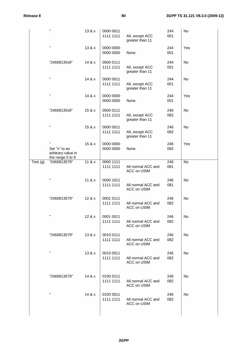
3GPP
Release 8 80 3GPP TS 31.121 V8.3.0 (2009-12)
" 13 & x 0000 0011 244 No 1111 1111 All, except ACC
greater than 11 001
" 13 & x 0000 0000 244 Yes 0000 0000 None 001 "24608135x9" 14 & x 0000 0111 244 No 1111 1111 All, except ACC
greater than 11 001
" 14 & x 0000 0011 244 No 1111 1111 All, except ACC
greater than 11 001
" 14 & x 0000 0000 244 Yes 0000 0000 None 001 "24608135x9" 15 & x 0000 0111 246 No 1111 1111 All, except ACC
greater than 11 082
" 15 & x 0000 0011 246 No 1111 1111 All, except ACC
greater than 11 082
" 15 & x 0000 0000 246 Yes Set "x" to an
arbitrary value in the range 0 to 9
0000 0000 None 082
Test (g) "2460813579" 11 & x 0000 1111 246 No 1111 1111 All normal ACC and
ACC on USIM 081
" 11 & x 0000 1011 246 No 1111 1111 All normal ACC and
ACC on USIM 081
"2460813579" 12 & x 0001 0111 246 No 1111 1111 All normal ACC and
ACC on USIM 082
" 12 & x 0001 0011 246 No 1111 1111 All normal ACC and
ACC on USIM 082
"2460813579" 13 & x 0010 0111 246 No 1111 1111 All normal ACC and
ACC on USIM 082
" 13 & x 0010 0011 246 No 1111 1111 All normal ACC and
ACC on USIM 082
"2460813579" 14 & x 0100 0111 246 No 1111 1111 All normal ACC and
ACC on USIM 082
" 14 & x 0100 0011 246 No 1111 1111 All normal ACC and
ACC on USIM 082

3GPP
Release 8 81 3GPP TS 31.121 V8.3.0 (2009-12)
"2460813579" 15 & x 1000 0111 246 No 1111 1111 All normal ACC and
ACC on USIM 081
" 15 & x 1000 0011 246 No Set "x" to an
arbitrary value in the range 0 to 9
1111 1111 All normal ACC and ACC on USIM
081
Test (h) "2460813579" 11 & x 1111 0011 246 Yes 1111 1111 All, except "special"
ACC on USIM 081
" 11 & x 1111 0111 246 Yes 1111 1111 All, except "special"
ACC on USIM 081
"2460813579" 12 & x 1110 1011 246 Yes 1111 1111 All, except "special"
ACC on USIM 082
" 12 & x 1110 1111 246 Yes 1111 1111 All, except "special"
ACC on USIM 082
"2460813579" 13 & x 1101 1011 246 Yes 1111 1111 All, except "special"
ACC on USIM 082
" 13 & x 1101 1111 246 Yes 1111 1111 All, except "special"
ACC on USIM 082
"2460813579" 14 & x 1011 1011 246 Yes 1111 1111 All, except "special"
ACC on USIM 082
" 14 & x 1011 1111 246 Yes 1111 1111 All, except "special"
ACC on USIM 082
"2460813579" 15 & x 0111 1011 246 Yes 1111 1111 All, except "special"
ACC on USIM 081
" 15 & x 0111 1111 246 Yes Set "x" to an
arbitrary value in the range 0 to 9
1111 1111 All, except "special" ACC on USIM
081
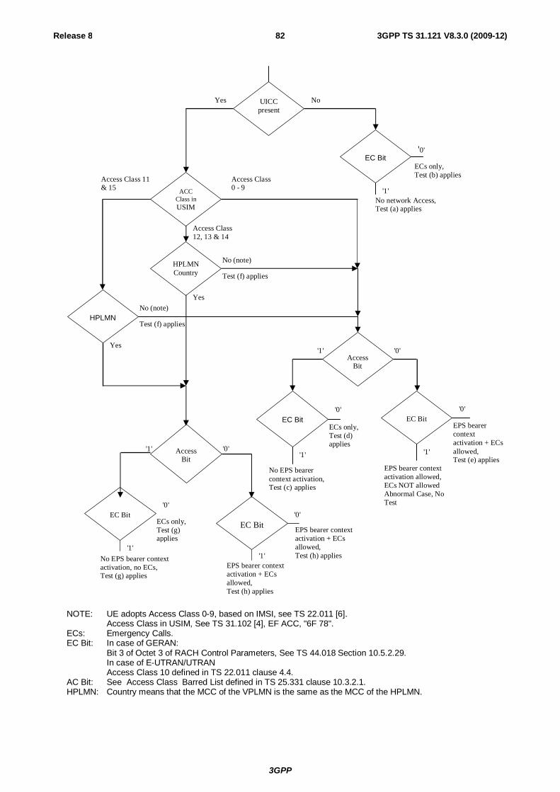
3GPP
Release 8 82 3GPP TS 31.121 V8.3.0 (2009-12)
NOTE: UE adopts Access Class 0-9, based on IMSI, see TS 22.011 [6]. Access Class in USIM, See TS 31.102 [4], EF ACC, "6F 78". ECs: Emergency Calls. EC Bit: In case of GERAN:
Bit 3 of Octet 3 of RACH Control Parameters, See TS 44.018 Section 10.5.2.29. In case of E-UTRAN/UTRAN Access Class 10 defined in TS 22.011 clause 4.4.
AC Bit: See Access Class Barred List defined in TS 25.331 clause 10.3.2.1. HPLMN: Country means that the MCC of the VPLMN is the same as the MCC of the HPLMN.
ECs only, Test (b) applies
No (note)
EC Bit
ACC Class in USIM
UICC present
Yes No
HPLMN
HPLMN Country
Access Bit
'1'
'0'
No (note)
Access Class 0 - 9
Access Class 11 & 15
Access Class 12, 13 & 14
No network Access, Test (a) applies
Test (f) applies
Test (f) applies
Access Bit
'1' '0'
EC Bit
'1'
'0'
ECs only, Test (d) applies
No EPS bearer context activation, Test (c) applies
EC Bit
'1'
'0'
EPS bearer context activation + ECs allowed, Test (e) applies
EPS bearer context activation allowed, ECs NOT allowed Abnormal Case, No Test
EC Bit
'1'
'0'
EPS bearer context activation + ECs allowed, Test (h) applies
EPS bearer context activation + ECs allowed, Test (h) applies
EC Bit
'1'
'0'
ECs only, Test (g) applies
No EPS bearer context activation, no ECs, Test (g) applies
Yes
'1' '0' Yes
3GPP
Release 8 83 3GPP TS 31.121 V8.3.0 (2009-12)
Figure 5-2: Access control information
6 Security related Tests 6.1 PIN handling 6.1.1 Entry of PIN 6.1.1.1 Definition and applicability
The PIN is a number used to authenticate the user to the UICC for security. Entry of the correct PIN allows PIN-protected data to be accessed over the UICC-Terminal interface.
Conformance requirement
Following insertion of the UICC and switching on the UE, the Terminal shall check the state of the PIN. If the PIN is enabled, the Terminal asks the user for PIN verification.
The VERIFY PIN function verifies the PIN presented by the Terminal to the UICC.
Reference:
- ETSI TS 102 221 [5], subclauses 9 and 11.1.9;
- TS 31.102 [4], clause 6;
- TS 22.030 [12], subclause 6.6.1.
6.1.1.3 Test purpose
1) To verify that the PIN verification procedure is performed by the Terminal correctly.
2) To verify that the basic public MMI string is supported.
6.1.1.4 Method of test
6.1.1.4.1 Initial conditions
The Terminal is connected to a UICC or UICC simulator with the PIN enabled, and powered off.
The default UICC is used.
6.1.1.4.2 Procedure
a) The Terminal is powered on.
b) When the UE is in the "PIN check" mode, the sequence "2468#" shall be entered.
6.1.1.5 Acceptance criteria
1) After step b) the Terminal shall send a VERIFY PIN command to the UICC, with parameter P2 = "01".
2) After step b) the UE shall give an indication "OK", following a successful execution of the command.
6.1.2 Change of PIN 6.1.2.1 Definition and applicability
The PIN may be changed by the user, by entering the old and new PIN. The length of the PIN is between 4 and 8 digits.
3GPP
Release 8 84 3GPP TS 31.121 V8.3.0 (2009-12)
Conformance requirement
The Terminal shall support the change of PIN procedure as defined in ETSI TS 102 221 [5], subclause 11.1.10.
Reference:
- ETSI TS 102 221 [5], subclauses 9 and 11.1.10;
- TS 31.102 [4], clause 6;
- TS 22.030 [12], subclause 6.6.2.
6.1.2.3 Test purpose
1) To verify that the PIN substitution procedure is performed correctly by the Terminal.
2) To verify that the basic public MMI string is supported.
6.1.2.4 Method of test
6.1.2.4.1 Initial conditions
The Terminal is connected to a UICC or UICC simulator with the PIN enabled.
The default UICC is used.
The Terminal is powered-on, with the correct PIN entered.
6.1.2.4.2 Procedure
a) Enter "**04*2468*01234567*01234567#" or initiate an equivalent MMI dependent procedure to change the PIN from '2468' to '01234567'.
b) The UE is switched off and on.
c) When the UE is in the "PIN check" mode, the sequence "2468#" shall be entered.
d) The UE is switched off and on.
e) When the UE is in the "PIN-check", mode the sequence "01234567#" shall be entered.
6.1.2.5 Acceptance criteria
1) After step a), the Terminal shall send a CHANGE PIN command to the UICC, with the parameter P2 set to "01".
2) Following the successful execution of the command, the UE shall give an indication that the new PIN is accepted.
3) After step c), the UE shall give an indication that the entered PIN is not accepted.
4) After step e), the UE shall give an indication "OK".
6.1.3 Unblock PIN 6.1.3.1 Definition and applicability
After three consecutive wrong entries of the PIN, the PIN shall become blocked. The Unblock PIN command is used to unblock the PIN. This function may be performed whether or not the PIN is blocked.
Conformance requirement
The Terminal shall support the Unblock PIN command, as defined in ETSI TS 102 221 [5], subclause 11.1.13.
Reference:
- ETSI TS 102 221 [5], subclause 11.1.13;
3GPP
Release 8 85 3GPP TS 31.121 V8.3.0 (2009-12)
- TS 31.102 [4], clause 6;
- TS 22.030 [12], subclause 6.6.3.
6.1.3.3 Test purpose
1) To verify that the PIN unblocking procedure is performed correctly.
2) To verify that the basic public MMI string is supported.
6.1.3.4 Method of test
6.1.3.4.1 Initial conditions
The Terminal is connected to the UICC simulator.
The default UICC is used.
6.1.3.4.2 Procedure
Sequence A:
a) The Terminal is powered on and the correct PIN is entered.
b) Enter "**05*13243546*1234*1234#"
c) The Terminal is powered off and on.
d) Enter the new PIN: "1234#".
e) The Terminal is powered off and on.
f) Enter a wrong PIN three times.
g) Enter "**05*13243546*2468*2468#".
h) The Terminal is powered off and on.
i) Enter the new PIN: "2468#".
Sequence B:
a) The Terminal is powered on.
b) Enter a wrong PIN three times.
c) The user shall initiate a MMI dependent procedure to unblock the PIN with unblock code '13243546' and a new PIN '2468'.
d) The Terminal is powered off and on.
e) Enter the new PIN: "2468#".
6.1.3.5 Acceptance criteria
Sequence A:
1) After step b), the Terminal shall send an UNBLOCK PIN command to the UICC, with parameter P2 = "01".
2) After step d), the Terminal shall indicate that the PIN has been accepted.
3) After step f), the Terminal shall indicate that the PIN has been blocked.
4) After step g), the Terminal shall send an UNBLOCK PIN command to the UICC, with parameter P2 = "01".
3GPP
Release 8 86 3GPP TS 31.121 V8.3.0 (2009-12)
5) After step i), the Terminal shall indicate that the PIN has been accepted.
Sequence B:
1) After step b), the Terminal shall indicate that the PIN has been blocked.
2) After step c), the Terminal shall send an UNBLOCK PIN command to the UICC, with parameter P2 = "01".
3) After step e), the Terminal shall indicate that the PIN has been accepted.
6.1.4 Entry of PIN2
6.1.4.1 Definition and applicability
The PIN2 is a number used to authenticate the user to the UICC for security. Entry of the correct PIN2 allows PIN2-protected data to be accessed over the UICC-Terminal interface.
Conformance requirement
Before allowing the access to PIN2 protected data, the Terminal shall ask the user for PIN2 verification. Only after presenting the PIN2, the user shall get access to these data.
The VERIFY PIN function verifies the PIN2 presented by the Terminal to the UICC.
Reference:
- ETSI TS 102 221 [5], subclauses 9 and 11.1.9;
- TS 31.102 [4], clause 6;
- TS 22.030 [12], subclause 6.6.1.
6.1.4.3 Test purpose
1) To verify that the PIN2 verification procedure is performed by the Terminal correctly.
2) To verify that the basic public MMI string is supported.
6.1.4.4 Method of test
6.1.4.4.1 Initial conditions
The Terminal is connected to a UICC or UICC simulator with the PIN enabled, and powered off.
The default UICC is used.
NOTE: To perform the UPDATE FDN data (as described in the procedure below), the default FDN UICC may be used.
6.1.4.4.2 Procedure
a) The Terminal is powered on and the correct PIN is entered.
b) The access to a PIN2 protected data field shall be performed (e.g. UPDATE FDN)
c) When the UE is in the "PIN2 check" mode, the sequence "3579#" shall be entered.
6.1.4.5 Acceptance criteria
1) After step c) the Terminal shall send a VERIFY PIN command to the UICC, with parameter P2 = "81".
2) After step c) the UE shall give an indication "OK", following a successful execution of the command.
3GPP
Release 8 87 3GPP TS 31.121 V8.3.0 (2009-12)
6.1.5 Change of PIN2
6.1.5.1 Definition and applicability
The PIN2 may be changed by the user, by entering the old and new PIN2. The length of the PIN2 is between 4 and 8 digits.
Conformance requirement
The Terminal shall support the change of PIN2 procedure as defined in ETSI TS 102 221 [5], subclause 11.1.10.
Reference:
- ETSI TS 102 221 [5], subclauses 9 and 11.1.10;
- TS 31.102 [4], clause 6;
- TS 22.030 [12], subclause 6.6.2.
6.1.5.3 Test purpose
1) To verify that the PIN2 substitution procedure is performed correctly by the Terminal.
2) To verify that the basic public MMI string is supported.
6.1.5.4 Method of test
6.1.5.4.1 Initial conditions
The Terminal is connected to a UICC or UICC simulator with the PIN2 enabled.
The default UICC is used.
NOTE: To perform the UPDATE FDN data (as described in the procedure below), the default FDN UICC may be used.
The Terminal is powered-on, with the correct PIN entered.
6.1.5.4.2 Procedure
a) Enter "**042*3579*12345678*12345678#" or initiate an equivalent MMI dependent procedure to change PIN2 from '3579' to '12345678'.
b) The UE is switched off and on and the correct PIN is entered.
c) The access to a PIN2 protected data field shall be performed (e.g. UPDATE FDN).
d) When the UE is in the "PIN2 check" mode, the sequence "3579#" shall be entered.
e) The UE is switched off and on and the correct PIN is entered.
f) The access to a PIN2 protected data field shall be performed (e.g. UPDATE FDN).
g) When the UE is in the "PIN2 check", mode the sequence "12345678#" shall be entered.
6.1.5.5 Acceptance criteria
1) After step a), the Terminal shall send a CHANGE PIN2 command to the UICC, with the parameter P2 set to "81".
2) Following the successful execution of the command, the UE shall give an indication that the new PIN2 is accepted.
3) After step d), the UE shall give an indication that the entered PIN2 is not accepted.
3GPP
Release 8 88 3GPP TS 31.121 V8.3.0 (2009-12)
4) After step g), the UE shall give an indication "OK".
6.1.6 Unblock PIN2 6.1.6.1 Definition and applicability
After three consecutive wrong entries of the PIN2, the PIN2 shall become blocked. The Unblock PIN2 command is used to unblock the PIN2. This function may be performed whether or not the PIN2 is blocked.
Conformance requirement
The Terminal shall support the Unblock PIN2 command, as defined in ETSI TS 102 221 [5], subclause 11.1.13.
Reference:
- ETSI TS 102 221 [5], subclauses 9 and 11.1.13;
- TS 31.102 [4], clause 6;
- TS 22.030 [12], subclause 6.6.3.
6.1.6.3 Test purpose
1) To verify that the PIN2 unblocking procedure is performed correctly.
2) To verify that the basic public MMI string is supported.
6.1.6.4 Method of test
6.1.6.4.1 Initial conditions
The Terminal is connected to the UICC simulator.
The default UICC is used.
NOTE: To perform the UPDATE FDN data (as described in the procedure below), the default FDN UICC may be used.
6.1.6.4.2 Procedure
Sequence A:
a) The Terminal is powered on and the correct PIN is entered.
b) Enter "**052*08978675*1234*1234#"
c) The Terminal is powered off and on and the correct PIN is entered.
d) The access to a PIN2 protected data field shall be performed (e.g. UPDATE FDN).
e) Enter the new PIN2: "1234#".
f) The Terminal is powered off and on and the correct PIN is entered.
g) The access to a PIN2 protected data field shall be performed (e.g. UPDATE FDN).
h) Enter a wrong PIN2 three times.
i) Enter "**052*08978675*3579*3579#".
j) The Terminal is powered off and on and the correct PIN is entered.
k) The access to a PIN2 protected data field shall be performed (e.g. UPDATE FDN).
l) Enter the new PIN2: "3579#".
3GPP
Release 8 89 3GPP TS 31.121 V8.3.0 (2009-12)
Sequence B:
a) The Terminal is powered on.
b) Enter a wrong PIN2 three times.
c) The user shall initiate a MMI dependent procedure to unblock the PIN2 with unblock code '08978675' and a new PIN '3579'.
d) The Terminal is powered off and on and the correct PIN is entered.
e) The access to a PIN2 protected data field shall be performed (e.g. UPDATE FDN).
f) Enter the new PIN2: "3579#".
6.1.6.5 Acceptance criterias
Sequence A:
1) After step b), the Terminal shall send an UNBLOCK PIN command to the UICC, with parameter P2 = "81".
2) After step e), the Terminal shall indicate that the PIN2 has been accepted.
3) After step h), the Terminal shall indicate that the PIN2 has been blocked.
4) After step i), the Terminal shall send an UNBLOCK PIN command to the UICC, with parameter P2 = "81".
5) After step l), the Terminal shall indicate that the PIN2 has been accepted.
Sequence B:
1) After step b), the Terminal shall indicate that the PIN2 has been blocked.
2) After step c), the Terminal shall send an UNBLOCK PIN command to the UICC, with parameter P2 = "81".
3) After step f), the Terminal shall indicate that the PIN2 has been accepted.
6.1.7 Replacement of PIN
6.1.7.1 Definition and applicability
The Universal PIN may be used to replace a PIN used to authenticate the user to the UICC for security. In this case entry of the correct Universal PIN allows PIN-protected data to be accessed over the UICC-Terminal interface. ETSI TS 102 221 [5] defines the range of "01" to "08" as key reference of the PIN on a multi-verification capable UICC.
Conformance requirement
The Terminal shall support the usage of the Universal PIN as replacement PIN and the replacement procedure as defined in ETSI TS 102 221 [5], subclause 11.1.11, as well as the procedure to disable the replacement defined in ETSI TS 102 221 [5], subclause 11.1.12.
Reference:
- ETSI TS 102 221 [5], subclauses 9, 11.1.11 and 11.1.12;
- TS 31.102 [4], clause 6.
6.1.7.3 Test purpose
1) To verify that the PIN replacement is supported by the Terminal correctly.
2) To verify that the PIN replacement procedure is performed by the Terminal correctly.
3) To verify that the procedure to disable the PIN replacement is performed by the Terminal correctly.
3GPP
Release 8 90 3GPP TS 31.121 V8.3.0 (2009-12)
6.1.7.4 Method of test
6.1.7.4.1 Initial conditions
The Terminal is connected to the UICC simulator with the PIN enabled, and powered off.
The default UICC is used.
6.1.7.4.2 Procedure
a) The Terminal is powered on.
b) When the Terminal is in the "PIN check" mode, the sequence "2468#" shall be entered.
c) The user shall initiate an MMI dependent procedure to replace the PIN by the Universal PIN.
d) The Terminal is powered off and on and when the Terminal is in "PIN check" mode the sequence "2468#" shall be entered.
e) The correct Universal PIN is entered.
f) The user shall initiate an MMI dependent procedure to disable the replacement of the PIN by the Universal PIN.
g) The Terminal is powered off and on and when the Terminal is in "PIN check" mode the sequence "2839#" shall be entered.
h) The correct PIN is entered.
6.1.7.5 Acceptance criteria
1) After step b) the Terminal shall send a VERIFY PIN command to the UICC, with parameter P2 = "01".
2) After step c), the Terminal shall send a DISABLE PIN command to the UICC, with parameter P1="91" and P2 = "01".
3) After step d) the Terminal shall send a VERIFY PIN command to the UICC, with parameter P2 = "11" and after unsuccessful execution of the command the Terminal shall indicate that the PIN has not been accepted.
4) After step e) the Terminal shall send a VERIFY PIN command to the UICC, with parameter P2 = "11" and after successful execution of the command the Terminal shall indicate that the PIN has been accepted.
5) After step f), the Terminal shall send an ENABLE PIN command to the UICC, with parameter P2 = "01".
6) After step g) the Terminal shall send a VERIFY PIN command to the UICC, with parameter P2 = "01" and after unsuccessful execution of the command the Terminal shall indicate that the PIN has not been accepted.
7) After step e) the Terminal shall send a VERIFY PIN command to the UICC, with parameter P2 = "01" and after successful execution of the command the Terminal shall indicate that the PIN has been accepted.
6.1.8 Change of Universal PIN
6.1.8.1 Definition and applicability
The Universal PIN may be changed by the user, by entering the old and new Universal PIN. The length of the Universal PIN is between 4 and 8 digits.
Conformance requirement
The Terminal shall support the change of PIN procedure as defined in ETSI TS 102 221 [5], subclause 11.1.10.
Reference:
- ETSI TS 102 221 [5], subclauses 9 and 11.1.10;
- TS 31.102 [4], clause 6.
3GPP
Release 8 91 3GPP TS 31.121 V8.3.0 (2009-12)
6.1.8.3 Test purpose
To verify that the PIN substitution procedure is performed correctly by the Terminal.
6.1.8.4 Method of test
6.1.8.4.1 Initial conditions
The Terminal is connected to a UICC or UICC simulator with the PIN enabled.
The default UICC is used with the following exception:
- The Universal PIN is used as a replacement of the PIN.
The Terminal is powered-on, with the correct Universal PIN entered.
6.1.8.4.2 Procedure
a) The user shall initiate an MMI dependent procedure to change the Universal PIN to "01234567".
b) The UE is switched off and on.
c) When the UE is in the "PIN check" mode, the sequence "2839#" shall be entered.
d) The UE is switched off and on.
e) When the UE is in the "PIN check", mode the sequence "01234567#" shall be entered.
6.1.8.5 Acceptance criteria
1) After step a), the Terminal shall send a CHANGE PIN command to the UICC, with the parameter P2 set to "11".
2) Following the successful execution of the command, the UE shall give an indication that the new (Universal) PIN is accepted.
3) After step c), the UE shall give an indication that the entered (Universal) PIN is not accepted.
4) After step e), the UE shall give an indication "OK".
6.1.9 Unblock Universal PIN
6.1.9.1 Definition and applicability
After three consecutive wrong entries of the PIN, the PIN shall become blocked. The Unblock PIN command is used to unblock the PIN. This function may be performed whether or not the PIN is blocked.
Conformance requirement
The Terminal shall support the Unblock PIN command, as defined in ETSI TS 102 221 [5], subclause 11.1.13.
Reference:
- ETSI TS 102 221 [5], subclause 11.1.13;
- TS 31.102 [4], clause 6.
6.1.9.3 Test purpose
To verify that the PIN unblocking procedure is performed correctly.
6.1.9.4 Method of test
6.1.9.4.1 Initial conditions
The Terminal is connected to the UICC simulator.
3GPP
Release 8 92 3GPP TS 31.121 V8.3.0 (2009-12)
The default UICC is used.
6.1.9.4.2 Procedure
a) The Terminal is powered on and the correct PIN is entered.
b) The user shall initiate an MMI dependent procedure to unblock the Universal PIN and set the new Universal PIN value to "1234"
c) The Terminal is powered off and on.
d) Enter the new PIN: "1234#".
e) The Terminal is powered off and on.
f) Enter a wrong PIN three times.
g) The user shall initiate an MMI dependent procedure to unblock the Universal PIN and set the new Universal PIN value to "2839".
h) The Terminal is powered off and on.
i) Enter the new PIN: "2839#".
6.1.9.5 Acceptance criteria
1) After step b), the Terminal shall send an UNBLOCK PIN command to the UICC, with parameter P2 = "11".
2) After step d), the Terminal shall indicate that the (Universal) PIN has been accepted.
3) After step f), the Terminal shall indicate that the (Universal) PIN has been blocked.
4) After step g), the Terminal shall send an UNBLOCK PIN command to the UICC, with parameter P2 = "11".
5) After step j), the Terminal shall indicate that the (Universal) PIN has been accepted.
6.1.10 Entry of PIN on multi-verification capable UICCs 6.1.10.1 Definition and applicability
The PIN is a number used to authenticate the user to the UICC for security. Entry of the correct PIN allows PIN-protected data to be accessed over the UICC-Terminal interface. ETSI TS 102 221 [5] defines the range of "01" to "08" as key reference of the PIN on a multi-verification capable UICC.
Conformance requirement
Following insertion of the UICC and switching on the UE, the Terminal shall check the state of the PIN. If the PIN is enabled, the Terminal asks the user for PIN verification.
The VERIFY PIN function verifies the PIN presented by the Terminal to the UICC.
Reference:
- ETSI TS 102 221 [5], subclauses 9 and 11.1.9;
- TS 31.102 [4], clause 6;
- TS 22.030 [12], subclause 6.6.1.
6.1.10.3 Test purpose
1) To verify that the PIN verification procedure is performed by the Terminal correctly.
2) To verify that the basic public MMI string is supported.
3) To verify that the Terminal supports key references in the range of "01" to "08" as PIN.
3GPP
Release 8 93 3GPP TS 31.121 V8.3.0 (2009-12)
6.1.10.4 Method of test
6.1.10.4.1 Initial conditions
The Terminal is connected to the UICC simulator with the PIN enabled, and powered off.
The default UICC is used with the following exceptions:
The UICC shall be configured to use "07" as the key reference of the PIN and "87" as key reference of the PIN2 with the following values:
PIN
Key reference: 07
Logically: 8642
Coding: B1 B2 B3 B4 B5 B6 B7 B8 Hex 38 36 34 32 FF FF FF FF
Unblock PIN
Key reference 07
Logically: 64534231
Coding: B1 B2 B3 B4 B5 B6 B7 B8 Hex 36 34 35 33 34 32 33 31
PIN2
Key reference 87
Logically: 9753
Coding: B1 B2 B3 B4 B5 B6 B7 B8 Hex 39 37 35 33 FF FF FF FF
Unblock PIN2
Key reference 87
Logically: 57687980
Coding: B1 B2 B3 B4 B5 B6 B7 B8 Hex 35 37 36 38 37 39 38 30
6.1.10.4.2 Procedure
a) The Terminal is powered on.
b) When the UE is in the "PIN check" mode, the sequence "8642#" shall be entered.
6.1.10.5 Acceptance criteria
1) After step b) the Terminal shall send a VERIFY PIN command to the UICC, with parameter P2 = "07".
2) After step b) the UE shall give an indication "OK", following a successful execution of the command.
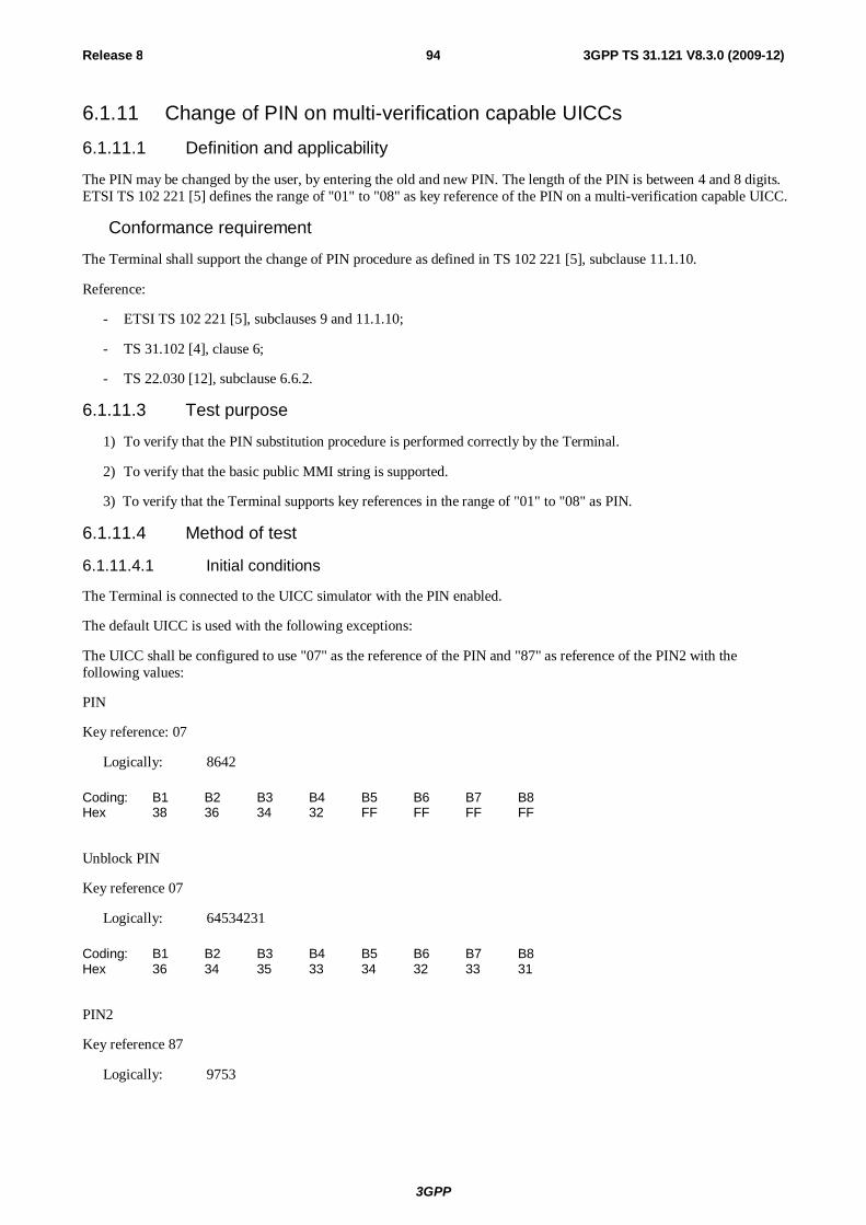
3GPP
Release 8 94 3GPP TS 31.121 V8.3.0 (2009-12)
6.1.11 Change of PIN on multi-verification capable UICCs
6.1.11.1 Definition and applicability
The PIN may be changed by the user, by entering the old and new PIN. The length of the PIN is between 4 and 8 digits. ETSI TS 102 221 [5] defines the range of "01" to "08" as key reference of the PIN on a multi-verification capable UICC.
Conformance requirement
The Terminal shall support the change of PIN procedure as defined in TS 102 221 [5], subclause 11.1.10.
Reference:
- ETSI TS 102 221 [5], subclauses 9 and 11.1.10;
- TS 31.102 [4], clause 6;
- TS 22.030 [12], subclause 6.6.2.
6.1.11.3 Test purpose
1) To verify that the PIN substitution procedure is performed correctly by the Terminal.
2) To verify that the basic public MMI string is supported.
3) To verify that the Terminal supports key references in the range of "01" to "08" as PIN.
6.1.11.4 Method of test
6.1.11.4.1 Initial conditions
The Terminal is connected to the UICC simulator with the PIN enabled.
The default UICC is used with the following exceptions:
The UICC shall be configured to use "07" as the reference of the PIN and "87" as reference of the PIN2 with the following values:
PIN
Key reference: 07
Logically: 8642
Coding: B1 B2 B3 B4 B5 B6 B7 B8 Hex 38 36 34 32 FF FF FF FF
Unblock PIN
Key reference 07
Logically: 64534231
Coding: B1 B2 B3 B4 B5 B6 B7 B8 Hex 36 34 35 33 34 32 33 31
PIN2
Key reference 87
Logically: 9753
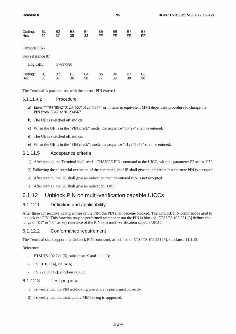
3GPP
Release 8 95 3GPP TS 31.121 V8.3.0 (2009-12)
Coding: B1 B2 B3 B4 B5 B6 B7 B8 Hex 39 37 35 33 FF FF FF FF
Unblock PIN2
Key reference 87
Logically: 57687980
Coding: B1 B2 B3 B4 B5 B6 B7 B8 Hex 35 37 36 38 37 39 38 30
The Terminal is powered-on, with the correct PIN entered.
6.1.11.4.2 Procedure
a) Enter "**04*8642*01234567*01234567#" or initiate an equivalent MMI dependent procedure to change the PIN from '8642' to '01234567'..
b) The UE is switched off and on.
c) When the UE is in the "PIN check" mode, the sequence "8642#" shall be entered.
d) The UE is switched off and on.
e) When the UE is in the "PIN check", mode the sequence "01234567#" shall be entered.
6.1.11.5 Acceptance criteria
1) After step a), the Terminal shall send a CHANGE PIN command to the UICC, with the parameter P2 set to "07".
2) Following the successful execution of the command, the UE shall give an indication that the new PIN is accepted.
3) After step c), the UE shall give an indication that the entered PIN is not accepted.
3) After step e), the UE shall give an indication "OK".
6.1.12 Unblock PIN on multi-verification capable UICCs 6.1.12.1 Definition and applicability
After three consecutive wrong entries of the PIN, the PIN shall become blocked. The Unblock PIN command is used to unblock the PIN. This function may be performed whether or not the PIN is blocked. ETSI TS 102 221 [5] defines the range of "01" to "08" as key reference of the PIN on a multi-verification capable UICC.
6.1.12.2 Conformance requirement
The Terminal shall support the Unblock PIN command, as defined in ETSI TS 102 221 [5], subclause 11.1.13.
Reference:
- ETSI TS 102 221 [5], subclauses 9 and 11.1.13;
- TS 31.102 [4], clause 6;
- TS 22.030 [12], subclause 6.6.3.
6.1.12.3 Test purpose
1) To verify that the PIN unblocking procedure is performed correctly.
2) To verify that the basic public MMI string is supported.
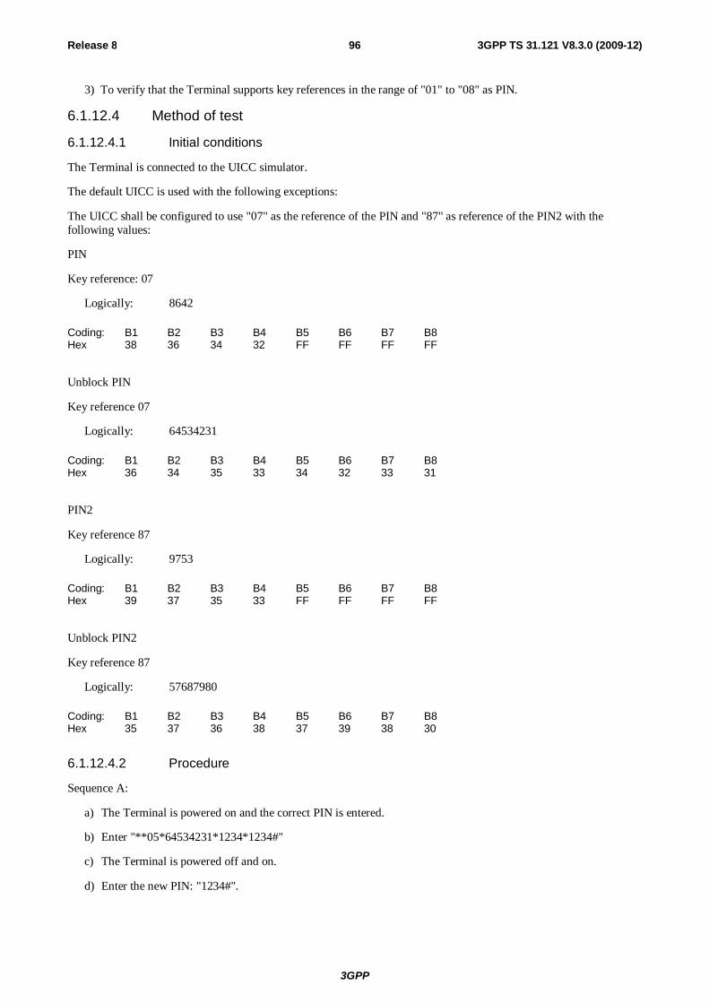
3GPP
Release 8 96 3GPP TS 31.121 V8.3.0 (2009-12)
3) To verify that the Terminal supports key references in the range of "01" to "08" as PIN.
6.1.12.4 Method of test
6.1.12.4.1 Initial conditions
The Terminal is connected to the UICC simulator.
The default UICC is used with the following exceptions:
The UICC shall be configured to use "07" as the reference of the PIN and "87" as reference of the PIN2 with the following values:
PIN
Key reference: 07
Logically: 8642
Coding: B1 B2 B3 B4 B5 B6 B7 B8 Hex 38 36 34 32 FF FF FF FF
Unblock PIN
Key reference 07
Logically: 64534231
Coding: B1 B2 B3 B4 B5 B6 B7 B8 Hex 36 34 35 33 34 32 33 31
PIN2
Key reference 87
Logically: 9753
Coding: B1 B2 B3 B4 B5 B6 B7 B8 Hex 39 37 35 33 FF FF FF FF
Unblock PIN2
Key reference 87
Logically: 57687980
Coding: B1 B2 B3 B4 B5 B6 B7 B8 Hex 35 37 36 38 37 39 38 30
6.1.12.4.2 Procedure
Sequence A:
a) The Terminal is powered on and the correct PIN is entered.
b) Enter "**05*64534231*1234*1234#"
c) The Terminal is powered off and on.
d) Enter the new PIN: "1234#".

3GPP
Release 8 97 3GPP TS 31.121 V8.3.0 (2009-12)
e) The Terminal is powered off and on.
f) Enter a wrong PIN three times.
g) Enter "**05*64534231*8642*8642#".
h) The Terminal is powered off and on.
i) Enter the new PIN: "8642#".
Sequence B:
a) The Terminal is powered on.
b) Enter a wrong PIN three times.
c) The user shall initiate a MMI dependent procedure to unblock the PIN with unblock code '64534231' and a new PIN '8642'.
d) The Terminal is powered off and on.
e) Enter the new PIN: "8642#".
6.1.12.5 Acceptance criteria
Sequence A:
1) After step b), the Terminal shall send an UNBLOCK PIN command to the UICC, with parameter P2 = "07".
2) After step d), the Terminal shall indicate that the PIN has been accepted.
3) After step f), the Terminal shall indicate that the PIN has been blocked.
4) After step g), the Terminal shall send an UNBLOCK PIN command to the UICC, with parameter P2 = "07".
5) After step j), the Terminal shall indicate that the PIN has been accepted.
Sequence B:
1) After step b), the Terminal shall indicate that the PIN has been blocked.
2) After step c), the Terminal shall send an UNBLOCK PIN command to the UICC, with parameter P2 = "07".
3) After step e), the Terminal shall indicate that the PIN has been accepted.
6.1.13 Entry of PIN2 on multi-verification capable UICCs
6.1.13.1 Definition and applicability
The PIN2 is a number used to authenticate the user to the UICC for security. Entry of the correct PIN2 allows PIN2-protected data to be accessed over the UICC-Terminal interface. ETSI TS 102 221 [5] defines the range of "81" to "88" as key reference of the PIN2 on a multi-verification capable UICC.
6.1.13.2 Conformance requirement
Before allowing the access to PIN2 protected data, the Terminal shall ask the user for PIN2 verification. Only after presenting the PIN2, the user shall get access to these data.
The VERIFY PIN function verifies the PIN2 presented by the Terminal to the UICC.
Reference:
- ETSI TS 102 221 [5], 9 and subclause 11.1.9;
- TS 31.102 [4], clause 6;
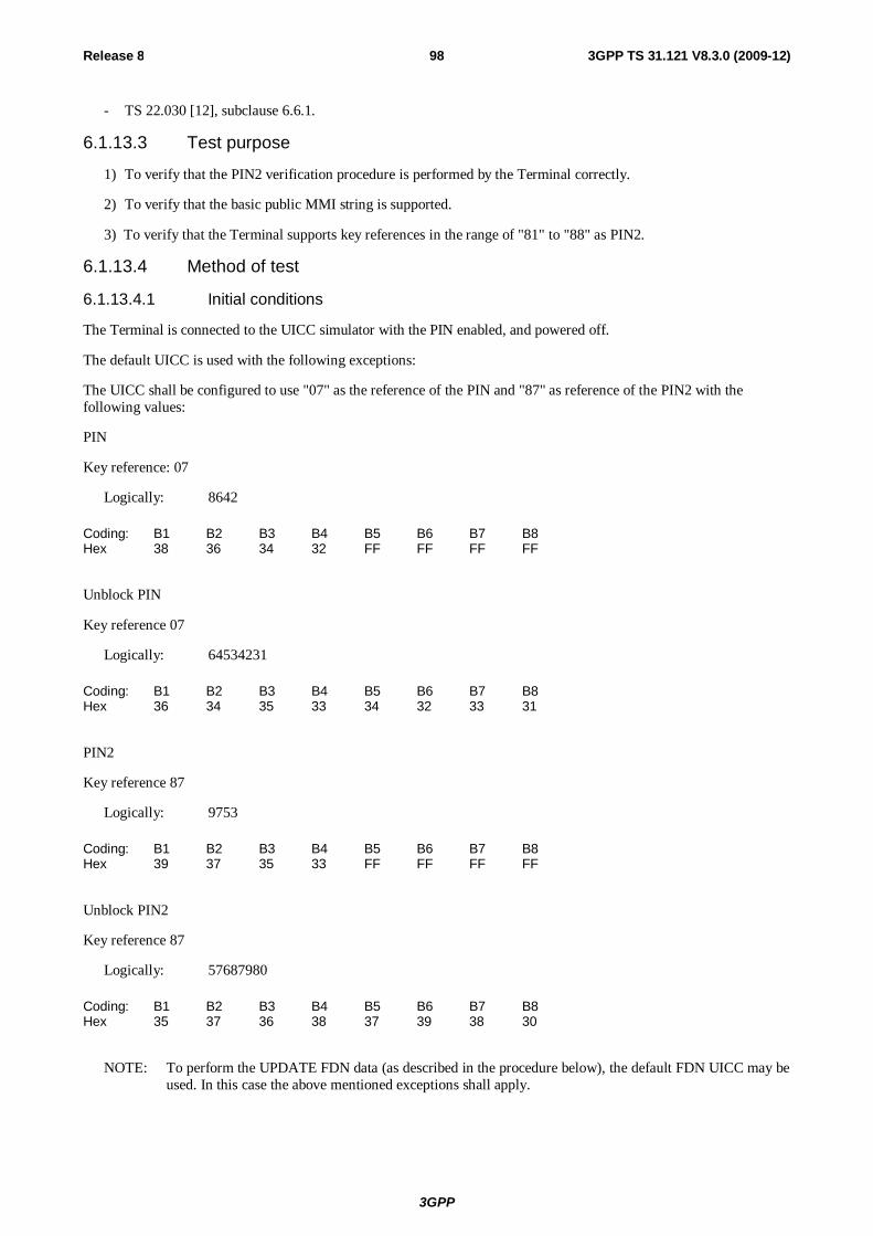
3GPP
Release 8 98 3GPP TS 31.121 V8.3.0 (2009-12)
- TS 22.030 [12], subclause 6.6.1.
6.1.13.3 Test purpose
1) To verify that the PIN2 verification procedure is performed by the Terminal correctly.
2) To verify that the basic public MMI string is supported.
3) To verify that the Terminal supports key references in the range of "81" to "88" as PIN2.
6.1.13.4 Method of test
6.1.13.4.1 Initial conditions
The Terminal is connected to the UICC simulator with the PIN enabled, and powered off.
The default UICC is used with the following exceptions:
The UICC shall be configured to use "07" as the reference of the PIN and "87" as reference of the PIN2 with the following values:
PIN
Key reference: 07
Logically: 8642
Coding: B1 B2 B3 B4 B5 B6 B7 B8 Hex 38 36 34 32 FF FF FF FF
Unblock PIN
Key reference 07
Logically: 64534231
Coding: B1 B2 B3 B4 B5 B6 B7 B8 Hex 36 34 35 33 34 32 33 31
PIN2
Key reference 87
Logically: 9753
Coding: B1 B2 B3 B4 B5 B6 B7 B8 Hex 39 37 35 33 FF FF FF FF
Unblock PIN2
Key reference 87
Logically: 57687980
Coding: B1 B2 B3 B4 B5 B6 B7 B8 Hex 35 37 36 38 37 39 38 30
NOTE: To perform the UPDATE FDN data (as described in the procedure below), the default FDN UICC may be used. In this case the above mentioned exceptions shall apply.
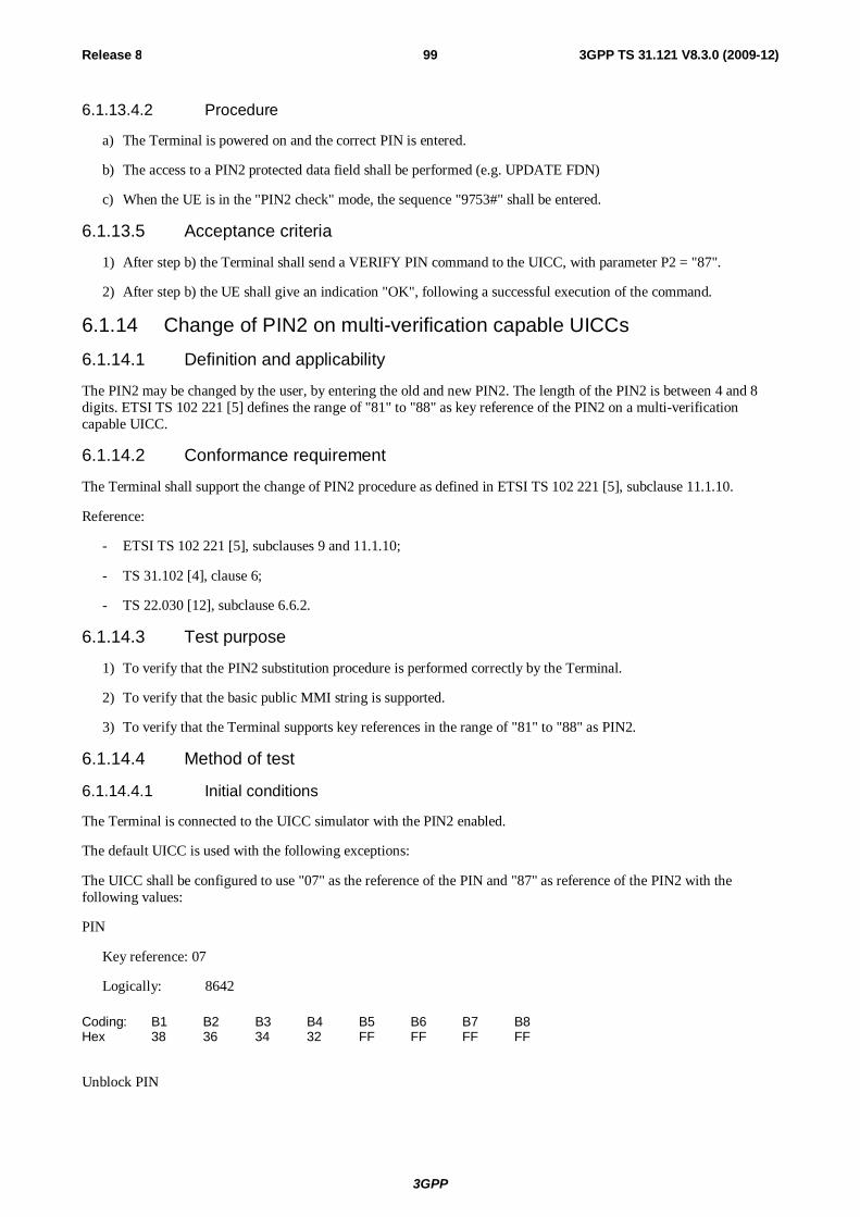
3GPP
Release 8 99 3GPP TS 31.121 V8.3.0 (2009-12)
6.1.13.4.2 Procedure
a) The Terminal is powered on and the correct PIN is entered.
b) The access to a PIN2 protected data field shall be performed (e.g. UPDATE FDN)
c) When the UE is in the "PIN2 check" mode, the sequence "9753#" shall be entered.
6.1.13.5 Acceptance criteria
1) After step b) the Terminal shall send a VERIFY PIN command to the UICC, with parameter P2 = "87".
2) After step b) the UE shall give an indication "OK", following a successful execution of the command.
6.1.14 Change of PIN2 on multi-verification capable UICCs 6.1.14.1 Definition and applicability
The PIN2 may be changed by the user, by entering the old and new PIN2. The length of the PIN2 is between 4 and 8 digits. ETSI TS 102 221 [5] defines the range of "81" to "88" as key reference of the PIN2 on a multi-verification capable UICC.
6.1.14.2 Conformance requirement
The Terminal shall support the change of PIN2 procedure as defined in ETSI TS 102 221 [5], subclause 11.1.10.
Reference:
- ETSI TS 102 221 [5], subclauses 9 and 11.1.10;
- TS 31.102 [4], clause 6;
- TS 22.030 [12], subclause 6.6.2.
6.1.14.3 Test purpose
1) To verify that the PIN2 substitution procedure is performed correctly by the Terminal.
2) To verify that the basic public MMI string is supported.
3) To verify that the Terminal supports key references in the range of "81" to "88" as PIN2.
6.1.14.4 Method of test
6.1.14.4.1 Initial conditions
The Terminal is connected to the UICC simulator with the PIN2 enabled.
The default UICC is used with the following exceptions:
The UICC shall be configured to use "07" as the reference of the PIN and "87" as reference of the PIN2 with the following values:
PIN
Key reference: 07
Logically: 8642
Coding: B1 B2 B3 B4 B5 B6 B7 B8 Hex 38 36 34 32 FF FF FF FF
Unblock PIN
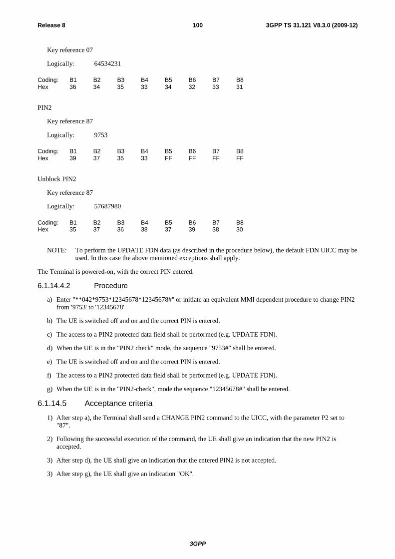
3GPP
Release 8 100 3GPP TS 31.121 V8.3.0 (2009-12)
Key reference 07
Logically: 64534231
Coding: B1 B2 B3 B4 B5 B6 B7 B8 Hex 36 34 35 33 34 32 33 31
PIN2
Key reference 87
Logically: 9753
Coding: B1 B2 B3 B4 B5 B6 B7 B8 Hex 39 37 35 33 FF FF FF FF
Unblock PIN2
Key reference 87
Logically: 57687980
Coding: B1 B2 B3 B4 B5 B6 B7 B8 Hex 35 37 36 38 37 39 38 30
NOTE: To perform the UPDATE FDN data (as described in the procedure below), the default FDN UICC may be used. In this case the above mentioned exceptions shall apply.
The Terminal is powered-on, with the correct PIN entered.
6.1.14.4.2 Procedure
a) Enter "**042*9753*12345678*12345678#" or initiate an equivalent MMI dependent procedure to change PIN2 from '9753' to '12345678'.
b) The UE is switched off and on and the correct PIN is entered.
c) The access to a PIN2 protected data field shall be performed (e.g. UPDATE FDN).
d) When the UE is in the "PIN2 check" mode, the sequence "9753#" shall be entered.
e) The UE is switched off and on and the correct PIN is entered.
f) The access to a PIN2 protected data field shall be performed (e.g. UPDATE FDN).
g) When the UE is in the "PIN2-check", mode the sequence "12345678#" shall be entered.
6.1.14.5 Acceptance criteria
1) After step a), the Terminal shall send a CHANGE PIN2 command to the UICC, with the parameter P2 set to "87".
2) Following the successful execution of the command, the UE shall give an indication that the new PIN2 is accepted.
3) After step d), the UE shall give an indication that the entered PIN2 is not accepted.
3) After step g), the UE shall give an indication "OK".
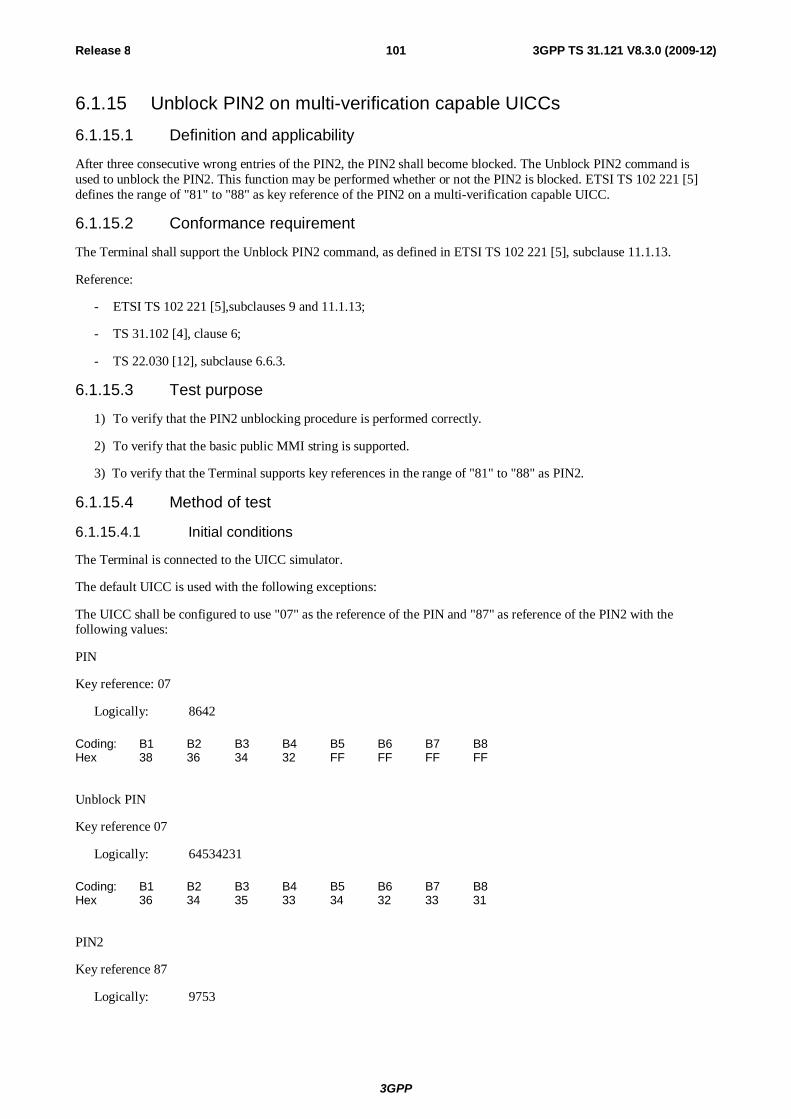
3GPP
Release 8 101 3GPP TS 31.121 V8.3.0 (2009-12)
6.1.15 Unblock PIN2 on multi-verification capable UICCs
6.1.15.1 Definition and applicability
After three consecutive wrong entries of the PIN2, the PIN2 shall become blocked. The Unblock PIN2 command is used to unblock the PIN2. This function may be performed whether or not the PIN2 is blocked. ETSI TS 102 221 [5] defines the range of "81" to "88" as key reference of the PIN2 on a multi-verification capable UICC.
6.1.15.2 Conformance requirement
The Terminal shall support the Unblock PIN2 command, as defined in ETSI TS 102 221 [5], subclause 11.1.13.
Reference:
- ETSI TS 102 221 [5],subclauses 9 and 11.1.13;
- TS 31.102 [4], clause 6;
- TS 22.030 [12], subclause 6.6.3.
6.1.15.3 Test purpose
1) To verify that the PIN2 unblocking procedure is performed correctly.
2) To verify that the basic public MMI string is supported.
3) To verify that the Terminal supports key references in the range of "81" to "88" as PIN2.
6.1.15.4 Method of test
6.1.15.4.1 Initial conditions
The Terminal is connected to the UICC simulator.
The default UICC is used with the following exceptions:
The UICC shall be configured to use "07" as the reference of the PIN and "87" as reference of the PIN2 with the following values:
PIN
Key reference: 07
Logically: 8642
Coding: B1 B2 B3 B4 B5 B6 B7 B8 Hex 38 36 34 32 FF FF FF FF
Unblock PIN
Key reference 07
Logically: 64534231
Coding: B1 B2 B3 B4 B5 B6 B7 B8 Hex 36 34 35 33 34 32 33 31
PIN2
Key reference 87
Logically: 9753
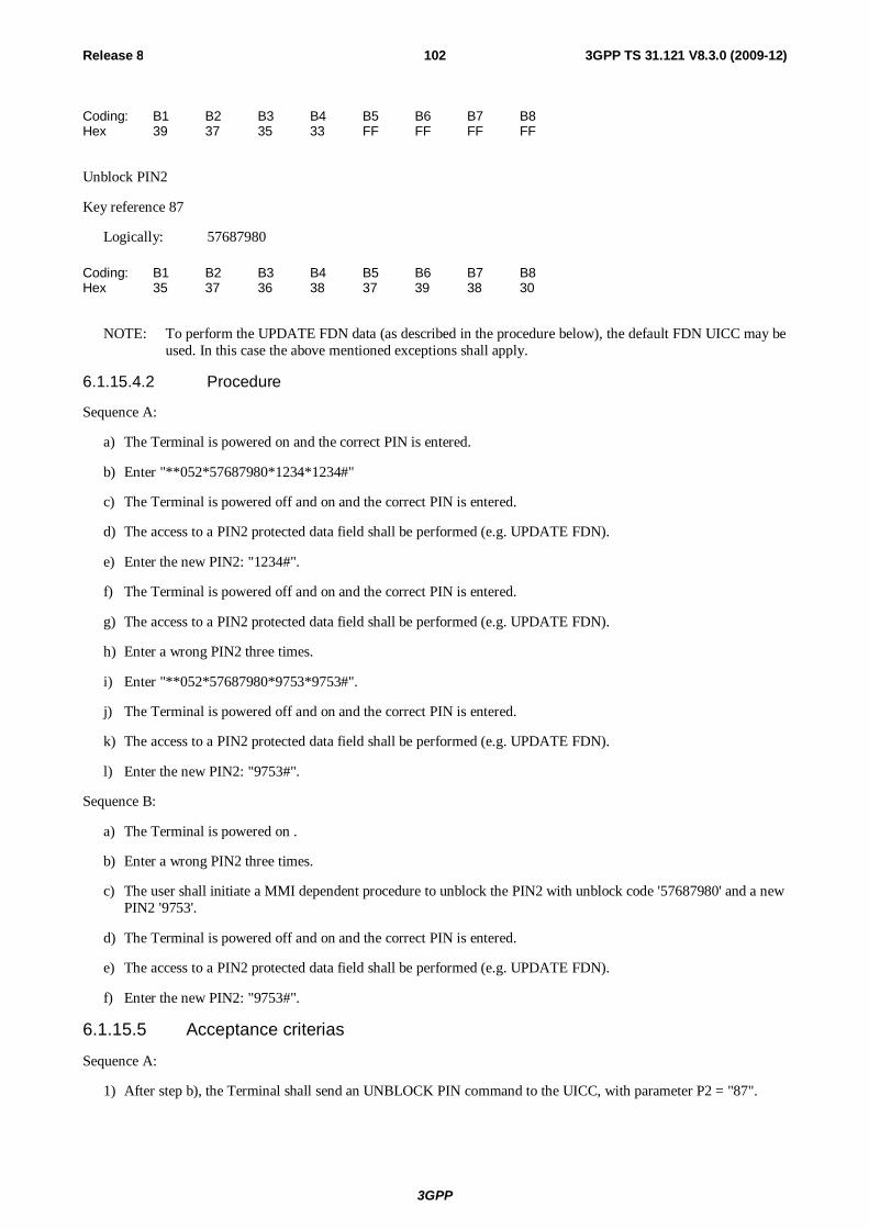
3GPP
Release 8 102 3GPP TS 31.121 V8.3.0 (2009-12)
Coding: B1 B2 B3 B4 B5 B6 B7 B8 Hex 39 37 35 33 FF FF FF FF
Unblock PIN2
Key reference 87
Logically: 57687980
Coding: B1 B2 B3 B4 B5 B6 B7 B8 Hex 35 37 36 38 37 39 38 30
NOTE: To perform the UPDATE FDN data (as described in the procedure below), the default FDN UICC may be used. In this case the above mentioned exceptions shall apply.
6.1.15.4.2 Procedure
Sequence A:
a) The Terminal is powered on and the correct PIN is entered.
b) Enter "**052*57687980*1234*1234#"
c) The Terminal is powered off and on and the correct PIN is entered.
d) The access to a PIN2 protected data field shall be performed (e.g. UPDATE FDN).
e) Enter the new PIN2: "1234#".
f) The Terminal is powered off and on and the correct PIN is entered.
g) The access to a PIN2 protected data field shall be performed (e.g. UPDATE FDN).
h) Enter a wrong PIN2 three times.
i) Enter "**052*57687980*9753*9753#".
j) The Terminal is powered off and on and the correct PIN is entered.
k) The access to a PIN2 protected data field shall be performed (e.g. UPDATE FDN).
l) Enter the new PIN2: "9753#".
Sequence B:
a) The Terminal is powered on .
b) Enter a wrong PIN2 three times.
c) The user shall initiate a MMI dependent procedure to unblock the PIN2 with unblock code '57687980' and a new PIN2 '9753'.
d) The Terminal is powered off and on and the correct PIN is entered.
e) The access to a PIN2 protected data field shall be performed (e.g. UPDATE FDN).
f) Enter the new PIN2: "9753#".
6.1.15.5 Acceptance criterias
Sequence A:
1) After step b), the Terminal shall send an UNBLOCK PIN command to the UICC, with parameter P2 = "87".
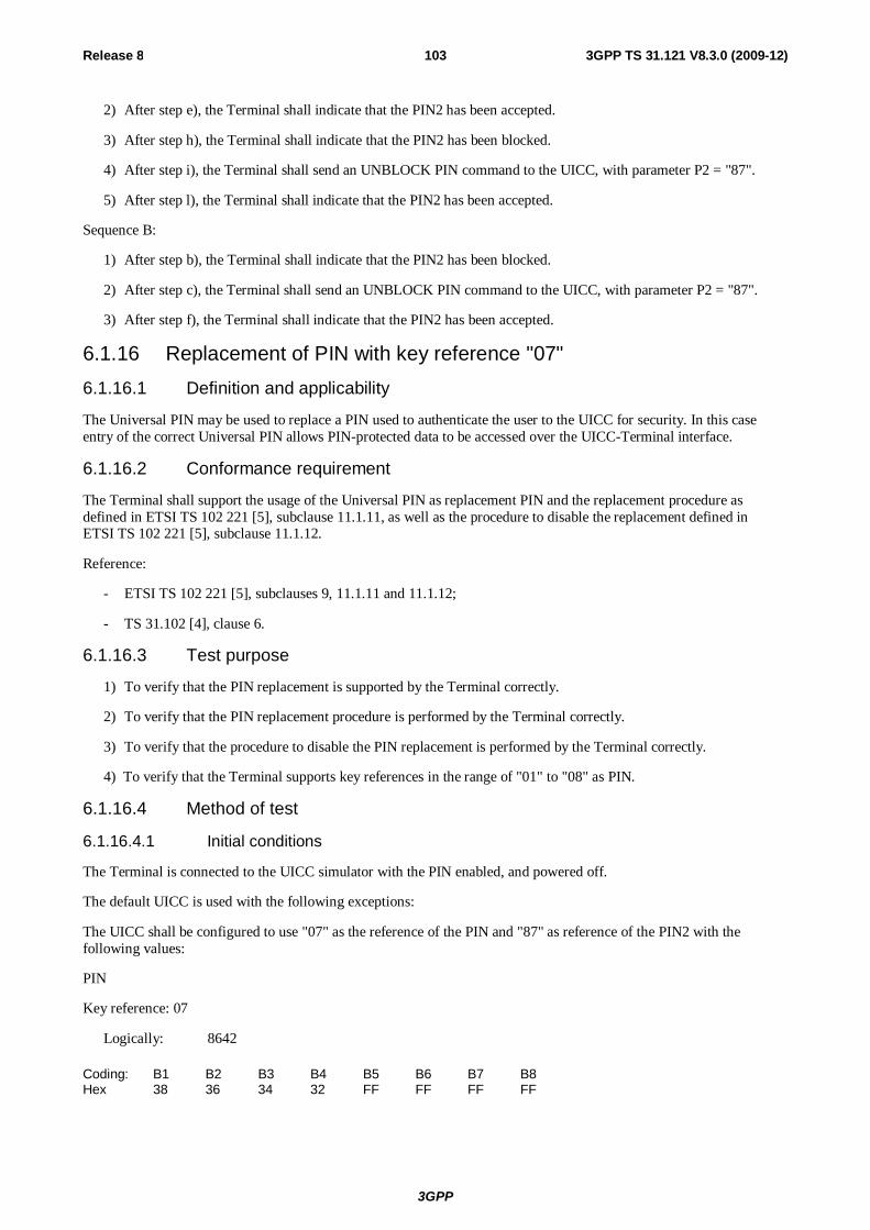
3GPP
Release 8 103 3GPP TS 31.121 V8.3.0 (2009-12)
2) After step e), the Terminal shall indicate that the PIN2 has been accepted.
3) After step h), the Terminal shall indicate that the PIN2 has been blocked.
4) After step i), the Terminal shall send an UNBLOCK PIN command to the UICC, with parameter P2 = "87".
5) After step l), the Terminal shall indicate that the PIN2 has been accepted.
Sequence B:
1) After step b), the Terminal shall indicate that the PIN2 has been blocked.
2) After step c), the Terminal shall send an UNBLOCK PIN command to the UICC, with parameter P2 = "87".
3) After step f), the Terminal shall indicate that the PIN2 has been accepted.
6.1.16 Replacement of PIN with key reference "07" 6.1.16.1 Definition and applicability
The Universal PIN may be used to replace a PIN used to authenticate the user to the UICC for security. In this case entry of the correct Universal PIN allows PIN-protected data to be accessed over the UICC-Terminal interface.
6.1.16.2 Conformance requirement
The Terminal shall support the usage of the Universal PIN as replacement PIN and the replacement procedure as defined in ETSI TS 102 221 [5], subclause 11.1.11, as well as the procedure to disable the replacement defined in ETSI TS 102 221 [5], subclause 11.1.12.
Reference:
- ETSI TS 102 221 [5], subclauses 9, 11.1.11 and 11.1.12;
- TS 31.102 [4], clause 6.
6.1.16.3 Test purpose
1) To verify that the PIN replacement is supported by the Terminal correctly.
2) To verify that the PIN replacement procedure is performed by the Terminal correctly.
3) To verify that the procedure to disable the PIN replacement is performed by the Terminal correctly.
4) To verify that the Terminal supports key references in the range of "01" to "08" as PIN.
6.1.16.4 Method of test
6.1.16.4.1 Initial conditions
The Terminal is connected to the UICC simulator with the PIN enabled, and powered off.
The default UICC is used with the following exceptions:
The UICC shall be configured to use "07" as the reference of the PIN and "87" as reference of the PIN2 with the following values:
PIN
Key reference: 07
Logically: 8642
Coding: B1 B2 B3 B4 B5 B6 B7 B8 Hex 38 36 34 32 FF FF FF FF
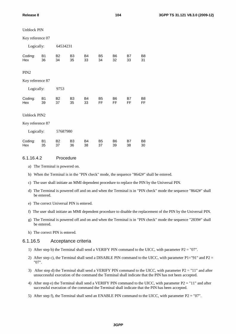
3GPP
Release 8 104 3GPP TS 31.121 V8.3.0 (2009-12)
Unblock PIN
Key reference 07
Logically: 64534231
Coding: B1 B2 B3 B4 B5 B6 B7 B8 Hex 36 34 35 33 34 32 33 31
PIN2
Key reference 87
Logically: 9753
Coding: B1 B2 B3 B4 B5 B6 B7 B8 Hex 39 37 35 33 FF FF FF FF
Unblock PIN2
Key reference 87
Logically: 57687980
Coding: B1 B2 B3 B4 B5 B6 B7 B8 Hex 35 37 36 38 37 39 38 30
6.1.16.4.2 Procedure
a) The Terminal is powered on.
b) When the Terminal is in the "PIN check" mode, the sequence "8642#" shall be entered.
c) The user shall initiate an MMI dependent procedure to replace the PIN by the Universal PIN.
d) The Terminal is powered off and on and when the Terminal is in "PIN check" mode the sequence "8642#" shall be entered.
e) The correct Universal PIN is entered.
f) The user shall initiate an MMI dependent procedure to disable the replacement of the PIN by the Universal PIN.
g) The Terminal is powered off and on and when the Terminal is in "PIN check" mode the sequence "2839#" shall be entered.
h) The correct PIN is entered.
6.1.16.5 Acceptance criteria
1) After step b) the Terminal shall send a VERIFY PIN command to the UICC, with parameter P2 = "07".
2) After step c), the Terminal shall send a DISABLE PIN command to the UICC, with parameter P1="91" and P2 = "07".
3) After step d) the Terminal shall send a VERIFY PIN command to the UICC, with parameter P2 = "11" and after unsuccessful execution of the command the Terminal shall indicate that the PIN has not been accepted.
4) After step e) the Terminal shall send a VERIFY PIN command to the UICC, with parameter P2 = "11" and after successful execution of the command the Terminal shall indicate that the PIN has been accepted.
5) After step f), the Terminal shall send an ENABLE PIN command to the UICC, with parameter P2 = "07".
3GPP
Release 8 105 3GPP TS 31.121 V8.3.0 (2009-12)
6) After step g) the Terminal shall send a VERIFY PIN command to the UICC, with parameter P2 = "07" and after unsuccessful execution of the command the Terminal shall indicate that the PIN has not been accepted.
7) After step e) the Terminal shall send a VERIFY PIN command to the UICC, with parameter P2 = "07" and after successful execution of the command the Terminal shall indicate that the PIN has been accepted.
6.2 Fixed Dialling Numbers (FDN) handling 6.2.1 Terminal and USIM with FDN enabled, EFADN readable and
updateable
6.2.1.1 Definition and applicability
Fixed Dialling Numbers (FDN) is a service defined for the USIM. An enabled FDN service results in call restrictions for the UE. The call restrictions are controlled by the Terminal. To ascertain the type of USIM and state of FDN the UE runs the FDN capability request procedure during UICC-Terminal initialisation. During the initialisation the Terminal shall request the Emergency call codes of the USIM EFECC. At the time an emergency call is setup using the emergency call code read from the EFECC, the UE shall use the category of the emergency service indicated.
6.2.1.2 Conformance requirement
1) Recognising the state of the USIM (FDN enabled) the UE shall perform the UICC initialisation procedure as specified.
2) The UE allows call set-up to a directory number as stored in EFFDN.
3) The UE allows call set-up to a directory number as stored in EFFDN and extended by digits in the end.
4) The UE does not allow call set-up to a directory number stored in EFFDN but with missing digits at the end.
5) The UE does not allow call set-up to a directory number having no reference in EFFDN.
6) The UE does not allow call set-up of an emergency call using the emergency numbers stored in the Terminal except "112", "911", the emergency numbers stored on the SIM/USIM and emergency numbers downloaded from the serving network (if any).
7) The UE allows call set-up of an emergency call using the emergency number stored in the USIM.
Reference:
- TS 22.101 [11], clauses 8 and A.24;
- TS 31.102 [4], subclauses 4.4.2, 4.2.24, 5.1.1 and 5.3.2;
- TS 24.008 [16], subclause 10.5.4.33.
6.2.1.3 Test purpose
1) To verify that the Terminal allows call set-up to a FDN number.
2) To verify that the Terminal allows call set-up to a FDN number extended by some digits in the end.
3) To verify that the Terminal rejects call set-up to number having no reference in EFFDN.
4) To verify that the Terminal rejects call set-up to a FDN number not completely corresponding to an entry in EFFDN.
5) To verify that the Terminal does not allow emergency call set-up using the emergency number stored in the Terminal except "112", "911", the emergency numbers stored on the SIM/USIM and emergency numbers downloaded from the serving network (if any).
6) To verify that the Terminal allows emergency call set-up using the emergency number stored in the UISM.
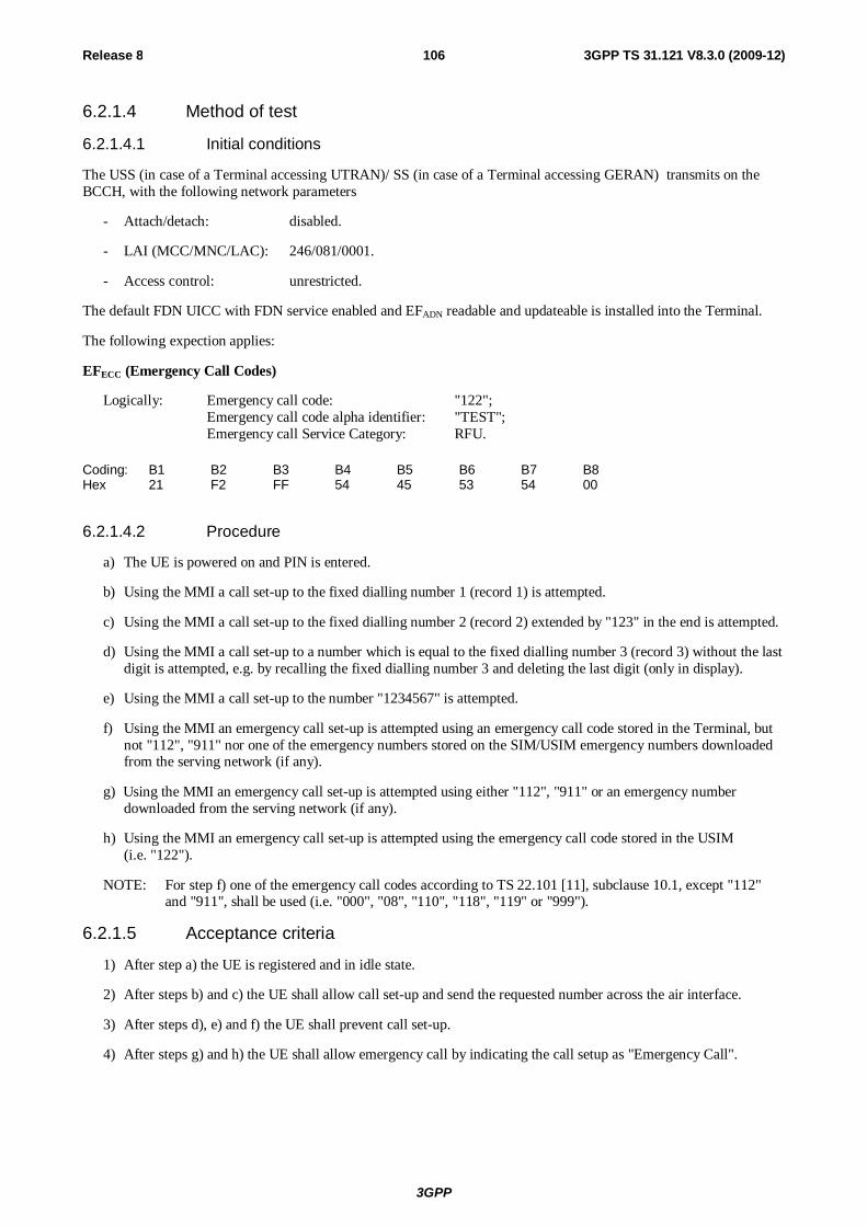
3GPP
Release 8 106 3GPP TS 31.121 V8.3.0 (2009-12)
6.2.1.4 Method of test
6.2.1.4.1 Initial conditions
The USS (in case of a Terminal accessing UTRAN)/ SS (in case of a Terminal accessing GERAN) transmits on the BCCH, with the following network parameters
- Attach/detach: disabled.
- LAI (MCC/MNC/LAC): 246/081/0001.
- Access control: unrestricted.
The default FDN UICC with FDN service enabled and EFADN readable and updateable is installed into the Terminal.
The following expection applies:
EFECC (Emergency Call Codes)
Logically: Emergency call code: "122"; Emergency call code alpha identifier: "TEST"; Emergency call Service Category: RFU.
Coding: B1 B2 B3 B4 B5 B6 B7 B8 Hex 21 F2 FF 54 45 53 54 00
6.2.1.4.2 Procedure
a) The UE is powered on and PIN is entered.
b) Using the MMI a call set-up to the fixed dialling number 1 (record 1) is attempted.
c) Using the MMI a call set-up to the fixed dialling number 2 (record 2) extended by "123" in the end is attempted.
d) Using the MMI a call set-up to a number which is equal to the fixed dialling number 3 (record 3) without the last digit is attempted, e.g. by recalling the fixed dialling number 3 and deleting the last digit (only in display).
e) Using the MMI a call set-up to the number "1234567" is attempted.
f) Using the MMI an emergency call set-up is attempted using an emergency call code stored in the Terminal, but not "112", "911" nor one of the emergency numbers stored on the SIM/USIM emergency numbers downloaded from the serving network (if any).
g) Using the MMI an emergency call set-up is attempted using either "112", "911" or an emergency number downloaded from the serving network (if any).
h) Using the MMI an emergency call set-up is attempted using the emergency call code stored in the USIM (i.e. "122").
NOTE: For step f) one of the emergency call codes according to TS 22.101 [11], subclause 10.1, except "112" and "911", shall be used (i.e. "000", "08", "110", "118", "119" or "999").
6.2.1.5 Acceptance criteria
1) After step a) the UE is registered and in idle state.
2) After steps b) and c) the UE shall allow call set-up and send the requested number across the air interface.
3) After steps d), e) and f) the UE shall prevent call set-up.
4) After steps g) and h) the UE shall allow emergency call by indicating the call setup as "Emergency Call".
3GPP
Release 8 107 3GPP TS 31.121 V8.3.0 (2009-12)
6.2.2 Terminal and USIM with FDN disabled
6.2.2.1 Definition and applicability
Fixed Dialling Numbers (FDN) is a service defined for the USIM. An enabled FDN service results in call restrictions for the UE. Only directory numbers which are stored in the EFFDN may be dialled by the UE. The call restrictions are controlled by the Terminal. To ascertain the type of USIM and state of FDN the UE runs the FDN capability request procedure during UICC-Terminal initialisation. Deactivation of the service by the subscriber is possible under the control of PIN2 and switches the USIM into a "normal", non restrictive USIM.
6.2.2.2 Conformance requirement
1) Recognising the state of the USIM (FDN disabled) the UE correctly performs the UICC initialisation procedure.
2) The UE allows call set-up to a directory number as stored in EFFDN.
3) The UE allows call set-up to a directory number as stored in EFADN.
4) The UE allows call set-up to a directory number given in manually.
Reference:
- R99: TS 22.101 [11], clauses 8 and A.24
- Rel-4: TS 22.101 [11], clauses 9 and A.25
- Rel-5, Rel-6: TS 22.101 [11], clauses 10 and A.25;
- TS 31.102 [4], subclauses 4.4.2.3, 4.2.24, 4.2.47, 5.1.1 and 5.3.2.
6.2.2.3 Test purpose
1) To verify that the Terminal as a result of the state of the USIM correctly performs the UICC-Terminal initialisation procedure.
2) To verify that the Terminal allows call set-up to a FDN number.
3) To verify that the Terminal allows call set-up to a ADN number.
4) To verify that the Terminal allows call set-up to manually given number.
6.2.2.4 Method of test
6.2.2.4.1 Initial conditions
The USS (in case of a Terminal accessing UTRAN) /SS (in case of a Terminal accessing GERAN) transmits on the BCCH, with the following network parameters:
- Attach/detach: disabled.
- LAI (MCC/MNC/LAC): 246/081/0001.
- Access control: unrestricted.
The default FDN UICC is used with the following exception:
EFEST (Enable Service Table)
Logically: Fixed Dialling Numbers disabled. Barred Dialling Numbers disabled. APN Control list (ACL) disabled.
Coding: B1 binary 0000 0000
3GPP
Release 8 108 3GPP TS 31.121 V8.3.0 (2009-12)
The UICC is installed into the Terminal and the UE is powered on.
6.2.2.4.2 Procedure
a) Using the MMI a call set-up to the fixed dialling number 1 is attempted.
b) Using the MMI a call set-up to the abbreviated dialling number 1 is attempted.
c) Using the MMI a call set-up to the number "1234567" is attempted.
6.2.2.5 Acceptance criteria
After steps a), b) and c) the UE shall allow call set-up and send the requested number across the air interface.
6.2.3 Enabling, disabling and updating of FDN 6.2.3.1 Definition and applicability
FDN may be enabled and disabled by the subscriber under control of PIN2. Fixed dialling numbers are read with PIN and updated under control of PIN2.
6.2.3.2 Conformance requirement
1) Recognising the state of the USIM (FDN enabled) the UE shall perform the UICC initialisation procedure as specified.
2) The UE shall allow updating of EFFDN by the use of PIN2.
3) The UE provides means to disable the FDN service by the use of PIN2.
4) The UE shall allow the use of EFADN after disabling of FDN.
Reference:
- R99: TS 22.101 [11], clauses 8 and A.24
- Rel-4: TS 22.101 [11], clauses 9 and A.25
- Rel-5, Rel-6: TS 22.101 [11], clause 10 and A.25;
- TS 31.102 [4], subclauses 4.4.2.3, 4.2.24, 4.2.47, 5.1.1 and 5.3.2.
6.2.3.3 Test purpose
1) To verify that the Terminal correctly performs the update of a number in EFFDN.
2) To verify that the Terminal correctly disables FDN service.
3) To verify that the Terminal recognises disabling of FDN and allows access to EFADN.
6.2.3.4 Method of test
6.2.3.4.1 Initial conditions
The USS (in case of a Terminal accessing UTRAN)/SS (in case of a Terminal accessing GERAN) transmits on the BCCH, with the following network parameters
- Attach/detach: disabled.
- LAI (MCC/MNC/LAC): 246/081/0001.
- Access control: unrestricted.
The default FDN UICC with FDN service enabled is installed into the Terminal.
3GPP
Release 8 109 3GPP TS 31.121 V8.3.0 (2009-12)
6.2.3.4.2 Procedure
a) The UE is powered on and PIN is entered.
b) Using the MMI the directory number "+876543210" is stored in EFFDN as fixed dialling number 1 (record 1). The alpha identifier is not changed. On request of the UE PIN2 is entered.
c) Using the MMI the FDN disabling procedure is performed. On request of the UE PIN2 is entered.
d) Using the MMI a call set-up to the abbreviated dialling number 1 (record 1) is attempted.
e) The UE is soft-powered down.
6.2.3.5 Acceptance criteria
1) After step a) the UE is registered and in idle state.
2) After step c) the UE shall indicate that the FDN disabling procedure has been successful.
3) After step d) the UE shall allow call set-up and send the requested number across the air interface.
4) After step e) record 1 in EFFDN , shall contain the following values:
B1 B2 B3 B4 B5 B6 B7 B8 B9 B10 B11 B12 B13 Hex 46 44 4E 31 31 31 06 91 78 56 34 12 F0 B14 B15 B16 B17 B18 B19 B20 FF FF FF FF FF FF FF
6.2.4 Terminal and USIM with FDN enabled, EFADN readable and updateable (Rel-4 and onwards)
6.2.4.1 Definition and applicability
Fixed Dialling Numbers (FDN) is a service defined for the USIM. An enabled FDN service results in call restrictions for the UE. The call restrictions are controlled by the Terminal. To ascertain the type of USIM and state of FDN the UE runs the FDN capability request procedure during UICC-Terminal initialisation. During the initialisation the Terminal shall request the Emergency call codes of the USIM EFECC. At the time an emergency call is setup using the emergency call code read from the EFECC, the UE shall use the category of the emergency service indicated.
6.2.4.2 Conformance requirement
1) Recognising the state of the USIM (FDN enabled) the UE shall perform the UICC initialisation procedure as specified.
2) The UE allows call set-up to a directory number as stored in EFFDN.
3) The UE allows call set-up to a directory number as stored in EFFDN and extended by digits in the end.
4) The UE does not allow call set-up to a directory number stored in EFFDN but with missing digits at the end.
5) The UE does not allow call set-up to a directory number having no reference in EFFDN.
6) The UE does not allow call set-up of an emergency call using the emergency numbers stored in the Terminal except "112", "911", the emergency numbers stored on the SIM/USIM and emergency numbers downloaded from the serving network (if any).
7) The UE allows call set-up of an emergency call using the emergency number stored in the USIM.
8) The UE shall indicate the emergency service category as "Mountain Rescue", when using the emergency number stored in the USIM.
Reference:
3GPP
Release 8 110 3GPP TS 31.121 V8.3.0 (2009-12)
- Rel-4: TS 22.101 [11], clauses 9 and A.25
- Rel-5, Rel-6: TS 22.101 [11], clauses 10 and A.25;
- TS 31.102 [4], subclauses 4.4.2, 4.2.24, 5.1.1 and 5.3.2;
- TS 24.008 [16], subclause 10.5.4.33.
6.2.4.3 Test purpose
1) To verify that the Terminal allows call set-up to a FDN number.
2) To verify that the Terminal allows call set-up to a FDN number extended by some digits in the end.
3) To verify that the Terminal rejects call set-up to number having no reference in EFFDN.
4) To verify that the Terminal rejects call set-up to a FDN number not completely corresponding to an entry in EFFDN.
5) To verify that the Terminal does not allow emergency call set-up using the emergency number stored in the Terminal except "112", "911", the emergency numbers stored on the SIM/USIM and emergency numbers downloaded from the serving network (if any).
6) To verify that the Terminal allows emergency call set-up using the emergency number stored in the UISM.
7) To verify that the Terminal reads correctly the emergency service category.
6.2.4.4 Method of test
6.2.4.4.1 Initial conditions
The USS (in case of a Terminal accessing UTRAN)/ SS (in case of a Terminal accessing GERAN) transmits on the BCCH, with the following network parameters
- Attach/detach: disabled.
- LAI (MCC/MNC/LAC): 246/081/0001.
- Access control: unrestricted.
The default FDN UICC with FDN service enabled and EFADN readable and updateable is installed into the Terminal.
6.2.4.4.2 Procedure
a) The UE is powered on and PIN is entered.
b) Using the MMI a call set-up to the fixed dialling number 1 (record 1) is attempted.
c) Using the MMI a call set-up to the fixed dialling number 2 (record 2) extended by "123" in the end is attempted.
d) Using the MMI a call set-up to a number which is equal to the fixed dialling number 3 (record 3) without the last digit is attempted, e.g. by recalling the fixed dialling number 3 and deleting the last digit (only in display).
e) Using the MMI a call set-up to the number "1234567" is attempted.
f) Using the MMI an emergency call set-up is attempted using an emergency call code stored in the Terminal, but not "112", "911" nor one of the emergency numbers stored on the SIM/USIM emergency numbers downloaded from the serving network (if any).
g) Using the MMI an emergency call set-up is attempted using either "112", "911" or an emergency number downloaded from the serving network (if any).
h) Using the MMI an emergency call set-up is attempted using the emergency call code stored in the USIM (i.e. "122").
3GPP
Release 8 111 3GPP TS 31.121 V8.3.0 (2009-12)
NOTE: For step f) one of the emergency call codes according to TS 22.101 [11], subclause 10.1, except "112" and "911", shall be used (i.e. "000", "08", "110", "118", "119" or "999").
6.2.4.5 Acceptance criteria
1) After step a) the UE is registered and in idle state.
2) After steps b) and c) the UE shall allow call set-up and send the requested number across the air interface.
3) After steps d), e) and f) the UE shall prevent call set-up.
4) After steps g) and h) the UE shall allow emergency call by indicating the call setup as "Emergency Call".
5) After step h) the UE shall send the emergency service category correctly as "Mountain Rescue".
6.3 Void
6.4 Advice of charge (AoC) handling 6.4.1 AoC not supported by USIM
6.4.1.1 Definition and applicability
If the Terminal under test supports Advice of Charge Charging, it shall still look at the capability of the USIM, before responding to any AoCC information from the network.
6.4.1.2 Conformance requirement
1) An UE not supporting AoCC and in the outgoing call / U4 call delivered state, on receipt of a CONNECT message containing AoCC information shall acknowledge the CONNECT message but ignore and not acknowledge the AoCC information sent within the CONNECT.
2) An UE not supporting AoCC and in the outgoing call / U4 call delivered state, on receipt of a FACILITY message containing AoCC information shall ignore and not acknowledge the AoCC information sent within the FACILITY.
3) An UE not supporting AoCC and in the incoming call / U9 call confirmed state, on receipt of a FACILITY message containing AoCC information shall ignore and not acknowledge the AoCC information sent within the FACILITY.
4) An UE not supporting AoCC and in the U10 call active state, on receipt of a FACILITY message containing AoCC information, shall ignore and not acknowledge the AoCC information sent within the FACILITY.
References:
- TS 24.008 [16], subclause 5.1.2.1;
- TS 23.086 [9], subclauses 1.2, 1.3, 2.2 and 2.3;
- TS 24.086 [10], clause 2.
6.4.1.3 Test purpose
1) To verify that an UE not supporting AoCC (where the Terminal does support AoCC but the USIM does not) and in the outgoing call / U4 call delivered state, on receipt of a CONNECT message containing AoCC information shall acknowledge the CONNECT message but ignore and not acknowledge the AoCC information sent within the CONNECT.
2) To verify that an UE not supporting AoCC (where the Terminal does support AoCC but the USIM does not) and in the outgoing call / U4 call delivered state, on receipt of a FACILITY message containing AoCC information shall ignore and not acknowledge the AoCC information sent within the FACILITY.
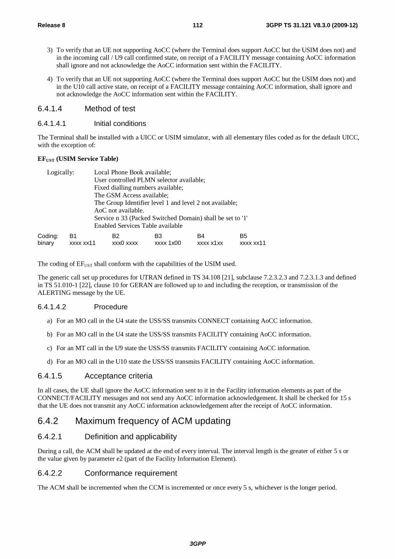
3GPP
Release 8 112 3GPP TS 31.121 V8.3.0 (2009-12)
3) To verify that an UE not supporting AoCC (where the Terminal does support AoCC but the USIM does not) and in the incoming call / U9 call confirmed state, on receipt of a FACILITY message containing AoCC information shall ignore and not acknowledge the AoCC information sent within the FACILITY.
4) To verify that an UE not supporting AoCC (where the Terminal does support AoCC but the USIM does not) and in the U10 call active state, on receipt of a FACILITY message containing AoCC information, shall ignore and not acknowledge the AoCC information sent within the FACILITY.
6.4.1.4 Method of test
6.4.1.4.1 Initial conditions
The Terminal shall be installed with a UICC or USIM simulator, with all elementary files coded as for the default UICC, with the exception of:
EFUST (USIM Service Table)
Logically: Local Phone Book available; User controlled PLMN selector available; Fixed dialling numbers available; The GSM Access available; The Group Identifier level 1 and level 2 not available; AoC not available. Service n 33 (Packed Switched Domain) shall be set to '1'
Enabled Services Table available
Coding: B1 B2 B3 B4 B5 binary xxxx xx11 xxx0 xxxx xxxx 1x00 xxxx x1xx xxxx xx11
The coding of EFUST shall conform with the capabilities of the USIM used.
The generic call set up procedures for UTRAN defined in TS 34.108 [21], subclause 7.2.3.2.3 and 7.2.3.1.3 and defined in TS 51.010-1 [22], clause 10 for GERAN are followed up to and including the reception, or transmission of the ALERTING message by the UE.
6.4.1.4.2 Procedure
a) For an MO call in the U4 state the USS/SS transmits CONNECT containing AoCC information.
b) For an MO call in the U4 state the USS/SS transmits FACILITY containing AoCC information.
c) For an MT call in the U9 state the USS/SS transmits FACILITY containing AoCC information.
d) For an MO call in the U10 state the USS/SS transmits FACILITY containing AoCC information.
6.4.1.5 Acceptance criteria
In all cases, the UE shall ignore the AoCC information sent to it in the Facility information elements as part of the CONNECT/FACILITY messages and not send any AoCC information acknowledgement. It shall be checked for 15 s that the UE does not transmit any AoCC information acknowledgement after the receipt of AoCC information.
6.4.2 Maximum frequency of ACM updating 6.4.2.1 Definition and applicability
During a call, the ACM shall be updated at the end of every interval. The interval length is the greater of either 5 s or the value given by parameter e2 (part of the Facility Information Element).
6.4.2.2 Conformance requirement
The ACM shall be incremented when the CCM is incremented or once every 5 s, whichever is the longer period.
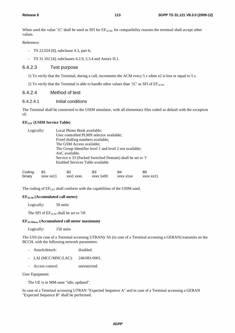
3GPP
Release 8 113 3GPP TS 31.121 V8.3.0 (2009-12)
When used the value '1C' shall be used as SFI for EFACM, for compatibility reasons the terminal shall accept other values.
Reference:
- TS 22.024 [8], subclause 4.3, part h;
- TS 31.102 [4], subclauses 4.2.9, 5.3.4 and Annex H.1.
6.4.2.3 Test purpose
1) To verify that the Terminal, during a call, increments the ACM every 5 s when e2 is less or equal to 5 s.
2) To verify that the Terminal is able to handle other values than '1C' as SFI of EFACM.
6.4.2.4 Method of test
6.4.2.4.1 Initial conditions
The Terminal shall be connected to the USIM simulator, with all elementary files coded as default with the exception of:
EFUST (USIM Service Table)
Logically: Local Phone Book available; User controlled PLMN selector available; Fixed dialling numbers available; The GSM Access available; The Group Identifier level 1 and level 2 not available; AoC available. Service n 33 (Packed Switched Domain) shall be set to '1'
Enabled Services Table available
Coding: B1 B2 B3 B4 B5 binary xxxx xx11 xxx1 xxxx xxxx 1x00 xxxx x1xx xxxx xx11
The coding of EFUST shall conform with the capabilities of the USIM used.
EFACM (Accumulated call meter)
Logically: 50 units
The SFI of EFACM shall be set to '18'.
EFACMmax (Accumulated call meter maximum)
Logically: 150 units
The USS (in case of a Terminal accessing UTRAN)/ SS (in case of a Terminal accessing a GERAN) transmits on the BCCH, with the following network parameters:
- Attach/detach: disabled.
- LAI (MCC/MNC/LAC): 246/081/0001.
- Access control: unrestricted.
User Equipment:
The UE is in MM-state "idle, updated".
In case of a Terminal accessing UTRAN "Expected Sequence A" and in case of a Terminal accessing a GERAN "Expected Sequence B" shall be performed.
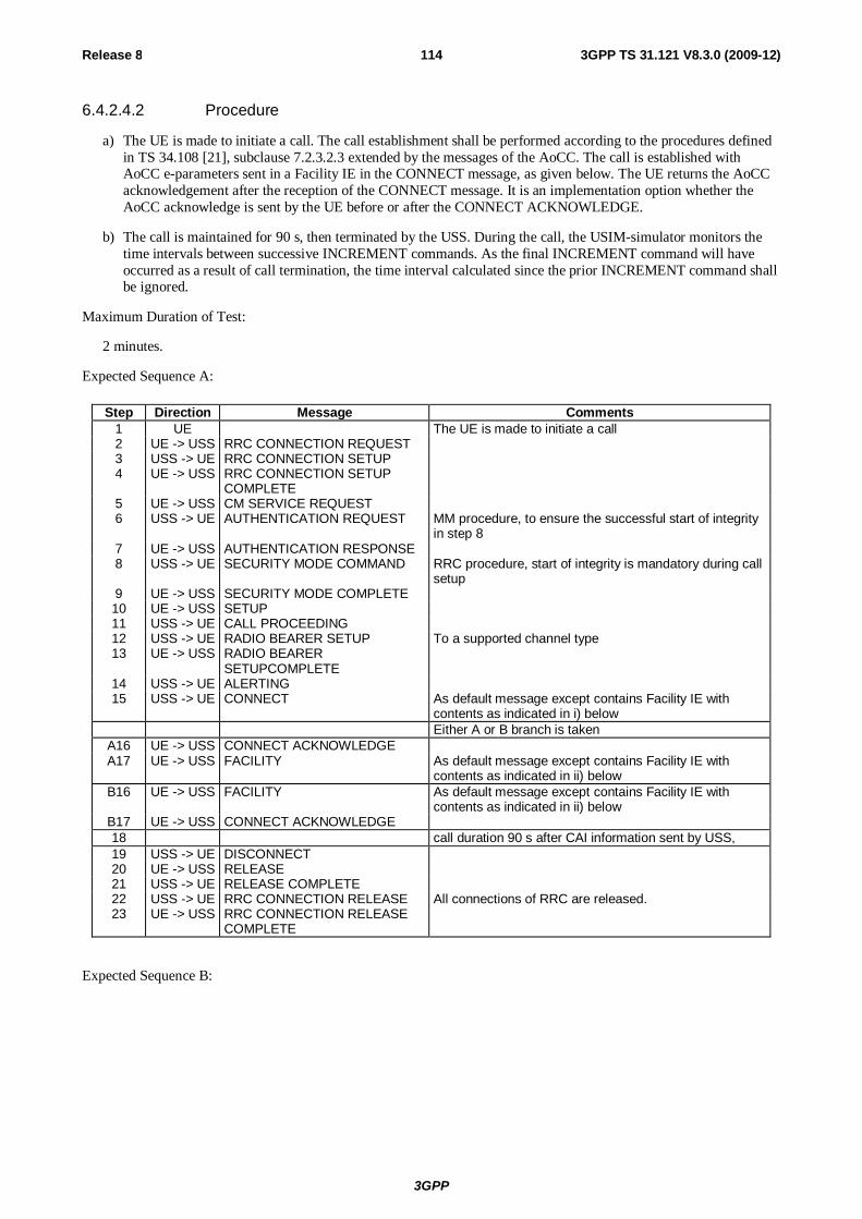
3GPP
Release 8 114 3GPP TS 31.121 V8.3.0 (2009-12)
6.4.2.4.2 Procedure
a) The UE is made to initiate a call. The call establishment shall be performed according to the procedures defined in TS 34.108 [21], subclause 7.2.3.2.3 extended by the messages of the AoCC. The call is established with AoCC e-parameters sent in a Facility IE in the CONNECT message, as given below. The UE returns the AoCC acknowledgement after the reception of the CONNECT message. It is an implementation option whether the AoCC acknowledge is sent by the UE before or after the CONNECT ACKNOWLEDGE.
b) The call is maintained for 90 s, then terminated by the USS. During the call, the USIM-simulator monitors the time intervals between successive INCREMENT commands. As the final INCREMENT command will have occurred as a result of call termination, the time interval calculated since the prior INCREMENT command shall be ignored.
Maximum Duration of Test:
2 minutes.
Expected Sequence A:
Step Direction Message Comments 1 UE The UE is made to initiate a call 2 UE -> USS RRC CONNECTION REQUEST 3 USS -> UE RRC CONNECTION SETUP 4 UE -> USS RRC CONNECTION SETUP
COMPLETE
5 UE -> USS CM SERVICE REQUEST 6 USS -> UE AUTHENTICATION REQUEST MM procedure, to ensure the successful start of integrity
in step 8 7 UE -> USS AUTHENTICATION RESPONSE 8 USS -> UE SECURITY MODE COMMAND RRC procedure, start of integrity is mandatory during call
setup 9 UE -> USS SECURITY MODE COMPLETE 10 UE -> USS SETUP 11 USS -> UE CALL PROCEEDING 12 USS -> UE RADIO BEARER SETUP To a supported channel type 13 UE -> USS RADIO BEARER
SETUPCOMPLETE
14 USS -> UE ALERTING 15 USS -> UE CONNECT As default message except contains Facility IE with
contents as indicated in i) below Either A or B branch is taken
A16 UE -> USS CONNECT ACKNOWLEDGE A17 UE -> USS FACILITY As default message except contains Facility IE with
contents as indicated in ii) below B16 UE -> USS FACILITY As default message except contains Facility IE with
contents as indicated in ii) below B17 UE -> USS CONNECT ACKNOWLEDGE 18 call duration 90 s after CAI information sent by USS, 19 USS -> UE DISCONNECT 20 UE -> USS RELEASE 21 USS -> UE RELEASE COMPLETE 22 USS -> UE RRC CONNECTION RELEASE All connections of RRC are released. 23 UE -> USS RRC CONNECTION RELEASE
COMPLETE
Expected Sequence B:
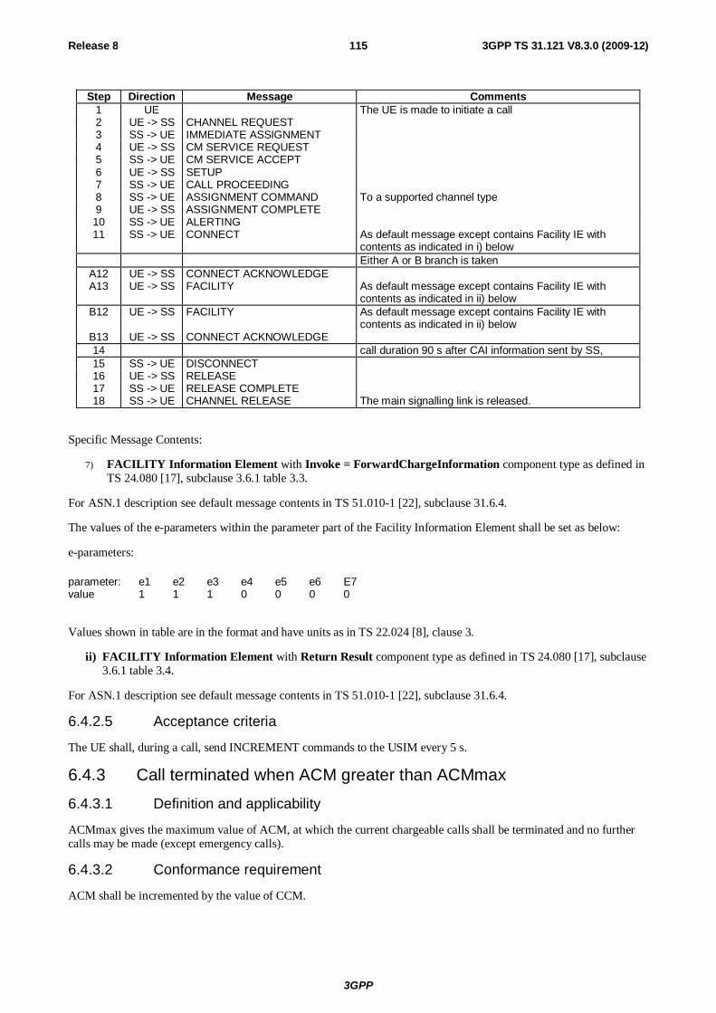
3GPP
Release 8 115 3GPP TS 31.121 V8.3.0 (2009-12)
Step Direction Message Comments 1 UE The UE is made to initiate a call 2 UE -> SS CHANNEL REQUEST 3 SS -> UE IMMEDIATE ASSIGNMENT 4 UE -> SS CM SERVICE REQUEST 5 SS -> UE CM SERVICE ACCEPT 6 UE -> SS SETUP 7 SS -> UE CALL PROCEEDING 8 SS -> UE ASSIGNMENT COMMAND To a supported channel type 9 UE -> SS ASSIGNMENT COMPLETE 10 SS -> UE ALERTING 11 SS -> UE CONNECT As default message except contains Facility IE with
contents as indicated in i) below Either A or B branch is taken
A12 UE -> SS CONNECT ACKNOWLEDGE A13 UE -> SS FACILITY As default message except contains Facility IE with
contents as indicated in ii) below B12 UE -> SS FACILITY As default message except contains Facility IE with
contents as indicated in ii) below B13 UE -> SS CONNECT ACKNOWLEDGE 14 call duration 90 s after CAI information sent by SS, 15 SS -> UE DISCONNECT 16 UE -> SS RELEASE 17 SS -> UE RELEASE COMPLETE 18 SS -> UE CHANNEL RELEASE The main signalling link is released.
Specific Message Contents:
7) FACILITY Information Element with Invoke = ForwardChargeInformation component type as defined in TS 24.080 [17], subclause 3.6.1 table 3.3.
For ASN.1 description see default message contents in TS 51.010-1 [22], subclause 31.6.4.
The values of the e-parameters within the parameter part of the Facility Information Element shall be set as below:
e-parameters:
parameter: e1 e2 e3 e4 e5 e6 E7 value 1 1 1 0 0 0 0
Values shown in table are in the format and have units as in TS 22.024 [8], clause 3.
ii) FACILITY Information Element with Return Result component type as defined in TS 24.080 [17], subclause 3.6.1 table 3.4.
For ASN.1 description see default message contents in TS 51.010-1 [22], subclause 31.6.4.
6.4.2.5 Acceptance criteria
The UE shall, during a call, send INCREMENT commands to the USIM every 5 s.
6.4.3 Call terminated when ACM greater than ACMmax
6.4.3.1 Definition and applicability
ACMmax gives the maximum value of ACM, at which the current chargeable calls shall be terminated and no further calls may be made (except emergency calls).
6.4.3.2 Conformance requirement
ACM shall be incremented by the value of CCM.
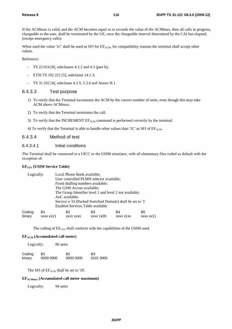
3GPP
Release 8 116 3GPP TS 31.121 V8.3.0 (2009-12)
If the ACMmax is valid, and the ACM becomes equal to or exceeds the value of the ACMmax, then all calls in progress, chargeable to the user, shall be terminated by the UE, once the chargeable interval determined by the CAI has elapsed, (except emergency calls).
When used the value '1C' shall be used as SFI for EFACM, for compatibility reasons the terminal shall accept other values.
Reference:
- TS 22.024 [8], subclauses 4.2.2 and 4.3 (part h);
- ETSI TS 102 221 [5], subclause 14.1.3;
- TS 31.102 [4], subclause 4.2.9, 5.3.4 and Annex H.1.
6.4.3.3 Test purpose
1) To verify that the Terminal increments the ACM by the correct number of units, even though this may take ACM above ACMmax.
2) To verify that the Terminal terminates the call.
3) To verify that the INCREMENT EFACM command is performed correctly by the terminal.
4) To verify that the Terminal is able to handle other values than '1C' as SFI of EFACM.
6.4.3.4 Method of test
6.4.3.4.1 Initial conditions
The Terminal shall be connected to a UICC or the USIM simulator, with all elementary files coded as default with the exception of:
EFUST (USIM Service Table)
Logically: Local Phone Book available; User controlled PLMN selector available; Fixed dialling numbers available; The GSM Access available; The Group Identifier level 1 and level 2 not available; AoC available. Service n 33 (Packed Switched Domain) shall be set to '1'
Enabled Services Table available
Coding: B1 B2 B3 B4 B5 binary xxxx xx11 xxx1 xxxx xxxx 1x00 xxxx x1xx xxxx xx11
The coding of EFUST shall conform with the capabilities of the USIM used.
EFACM (Accumulated call meter)
Logically: 80 units
Coding: B1 B2 B3 binary 0000 0000 0000 0000 0101 0000
The SFI of EFACM shall be set to '18'.
EFACMmax (Accumulated call meter maximum)
Logically: 94 units
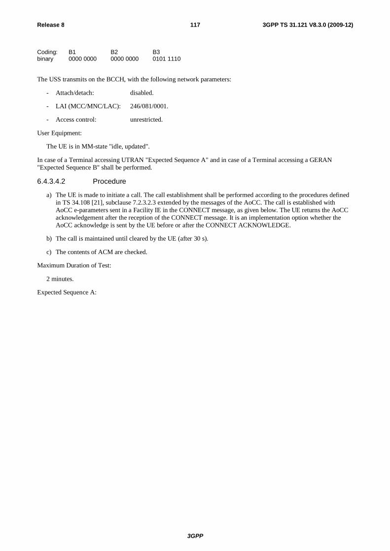
3GPP
Release 8 117 3GPP TS 31.121 V8.3.0 (2009-12)
Coding: B1 B2 B3 binary 0000 0000 0000 0000 0101 1110
The USS transmits on the BCCH, with the following network parameters:
- Attach/detach: disabled.
- LAI (MCC/MNC/LAC): 246/081/0001.
- Access control: unrestricted.
User Equipment:
The UE is in MM-state "idle, updated".
In case of a Terminal accessing UTRAN "Expected Sequence A" and in case of a Terminal accessing a GERAN "Expected Sequence B" shall be performed.
6.4.3.4.2 Procedure
a) The UE is made to initiate a call. The call establishment shall be performed according to the procedures defined in TS 34.108 [21], subclause 7.2.3.2.3 extended by the messages of the AoCC. The call is established with AoCC e-parameters sent in a Facility IE in the CONNECT message, as given below. The UE returns the AoCC acknowledgement after the reception of the CONNECT message. It is an implementation option whether the AoCC acknowledge is sent by the UE before or after the CONNECT ACKNOWLEDGE.
b) The call is maintained until cleared by the UE (after 30 s).
c) The contents of ACM are checked.
Maximum Duration of Test:
2 minutes.
Expected Sequence A:
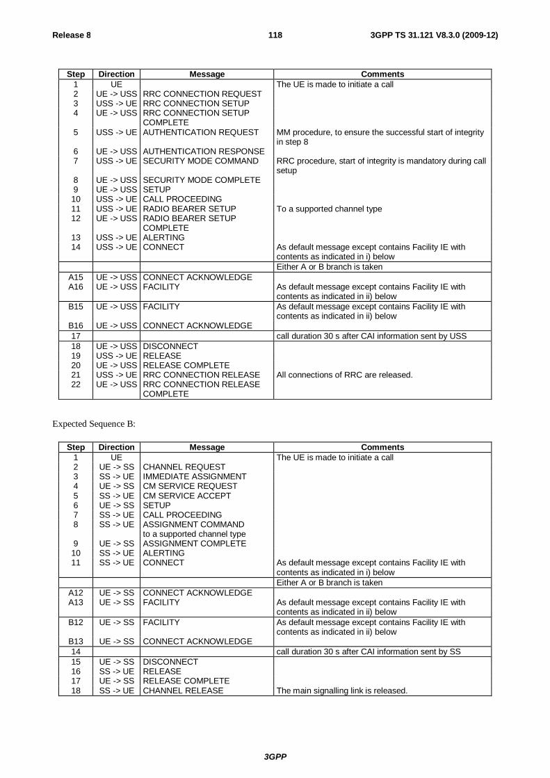
3GPP
Release 8 118 3GPP TS 31.121 V8.3.0 (2009-12)
Step Direction Message Comments 1 UE The UE is made to initiate a call 2 UE -> USS RRC CONNECTION REQUEST 3 USS -> UE RRC CONNECTION SETUP 4 UE -> USS RRC CONNECTION SETUP
COMPLETE
5 USS -> UE AUTHENTICATION REQUEST MM procedure, to ensure the successful start of integrity in step 8
6 UE -> USS AUTHENTICATION RESPONSE 7 USS -> UE SECURITY MODE COMMAND RRC procedure, start of integrity is mandatory during call
setup 8 UE -> USS SECURITY MODE COMPLETE 9 UE -> USS SETUP 10 USS -> UE CALL PROCEEDING 11 USS -> UE RADIO BEARER SETUP To a supported channel type 12 UE -> USS RADIO BEARER SETUP
COMPLETE
13 USS -> UE ALERTING 14 USS -> UE CONNECT As default message except contains Facility IE with
contents as indicated in i) below Either A or B branch is taken
A15 UE -> USS CONNECT ACKNOWLEDGE A16 UE -> USS FACILITY As default message except contains Facility IE with
contents as indicated in ii) below B15 UE -> USS FACILITY As default message except contains Facility IE with
contents as indicated in ii) below B16 UE -> USS CONNECT ACKNOWLEDGE 17 call duration 30 s after CAI information sent by USS 18 UE -> USS DISCONNECT 19 USS -> UE RELEASE 20 UE -> USS RELEASE COMPLETE 21 USS -> UE RRC CONNECTION RELEASE All connections of RRC are released. 22 UE -> USS RRC CONNECTION RELEASE
COMPLETE
Expected Sequence B:
Step Direction Message Comments 1 UE The UE is made to initiate a call 2 UE -> SS CHANNEL REQUEST 3 SS -> UE IMMEDIATE ASSIGNMENT 4 UE -> SS CM SERVICE REQUEST 5 SS -> UE CM SERVICE ACCEPT 6 UE -> SS SETUP 7 SS -> UE CALL PROCEEDING 8 SS -> UE ASSIGNMENT COMMAND to a supported channel type
9 UE -> SS ASSIGNMENT COMPLETE 10 SS -> UE ALERTING 11 SS -> UE CONNECT As default message except contains Facility IE with
contents as indicated in i) below Either A or B branch is taken
A12 UE -> SS CONNECT ACKNOWLEDGE A13 UE -> SS FACILITY As default message except contains Facility IE with
contents as indicated in ii) below B12 UE -> SS FACILITY As default message except contains Facility IE with
contents as indicated in ii) below B13 UE -> SS CONNECT ACKNOWLEDGE 14 call duration 30 s after CAI information sent by SS 15 UE -> SS DISCONNECT 16 SS -> UE RELEASE 17 UE -> SS RELEASE COMPLETE 18 SS -> UE CHANNEL RELEASE The main signalling link is released.
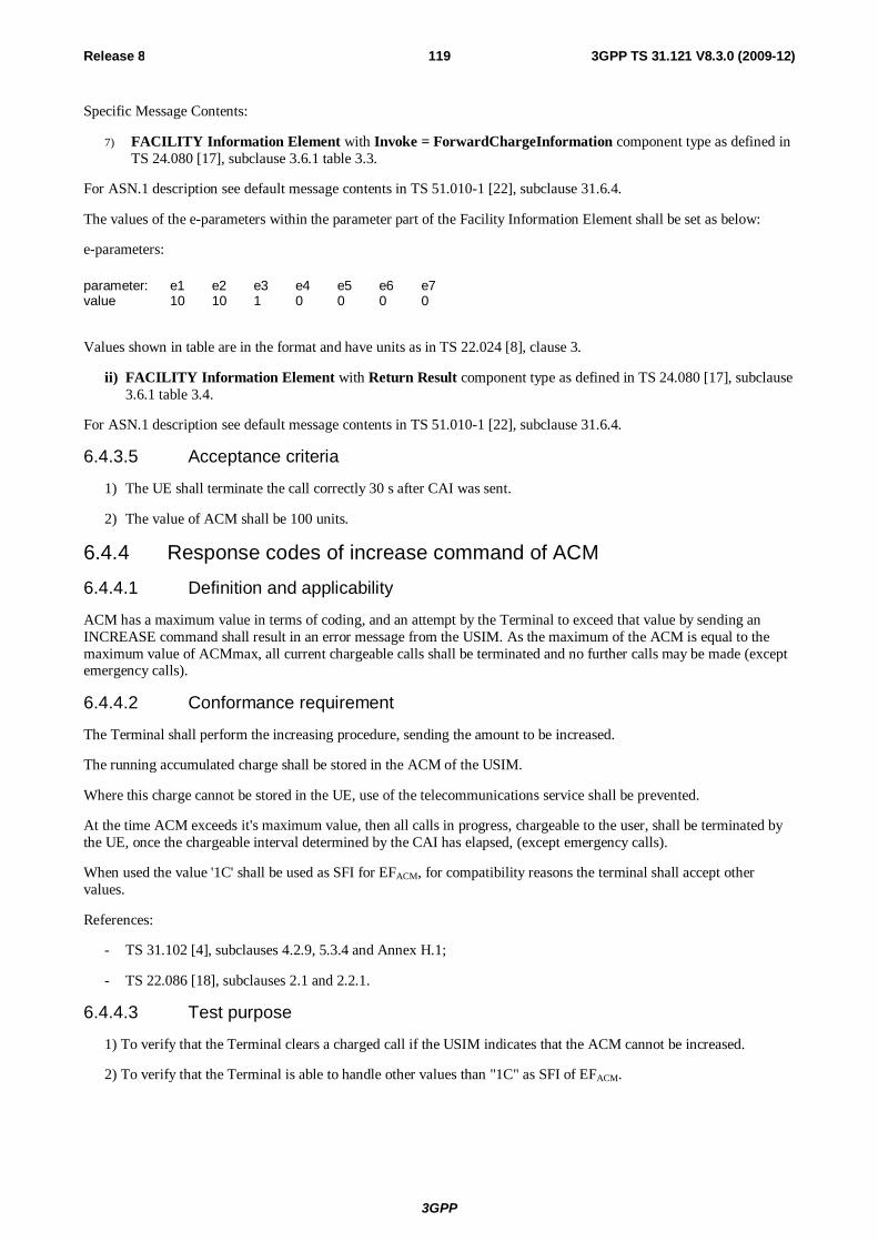
3GPP
Release 8 119 3GPP TS 31.121 V8.3.0 (2009-12)
Specific Message Contents:
7) FACILITY Information Element with Invoke = ForwardChargeInformation component type as defined in TS 24.080 [17], subclause 3.6.1 table 3.3.
For ASN.1 description see default message contents in TS 51.010-1 [22], subclause 31.6.4.
The values of the e-parameters within the parameter part of the Facility Information Element shall be set as below:
e-parameters:
parameter: e1 e2 e3 e4 e5 e6 e7 value 10 10 1 0 0 0 0
Values shown in table are in the format and have units as in TS 22.024 [8], clause 3.
ii) FACILITY Information Element with Return Result component type as defined in TS 24.080 [17], subclause 3.6.1 table 3.4.
For ASN.1 description see default message contents in TS 51.010-1 [22], subclause 31.6.4.
6.4.3.5 Acceptance criteria
1) The UE shall terminate the call correctly 30 s after CAI was sent.
2) The value of ACM shall be 100 units.
6.4.4 Response codes of increase command of ACM
6.4.4.1 Definition and applicability
ACM has a maximum value in terms of coding, and an attempt by the Terminal to exceed that value by sending an INCREASE command shall result in an error message from the USIM. As the maximum of the ACM is equal to the maximum value of ACMmax, all current chargeable calls shall be terminated and no further calls may be made (except emergency calls).
6.4.4.2 Conformance requirement
The Terminal shall perform the increasing procedure, sending the amount to be increased.
The running accumulated charge shall be stored in the ACM of the USIM.
Where this charge cannot be stored in the UE, use of the telecommunications service shall be prevented.
At the time ACM exceeds it's maximum value, then all calls in progress, chargeable to the user, shall be terminated by the UE, once the chargeable interval determined by the CAI has elapsed, (except emergency calls).
When used the value '1C' shall be used as SFI for EFACM, for compatibility reasons the terminal shall accept other values.
References:
- TS 31.102 [4], subclauses 4.2.9, 5.3.4 and Annex H.1;
- TS 22.086 [18], subclauses 2.1 and 2.2.1.
6.4.4.3 Test purpose
1) To verify that the Terminal clears a charged call if the USIM indicates that the ACM cannot be increased.
2) To verify that the Terminal is able to handle other values than "1C" as SFI of EFACM.
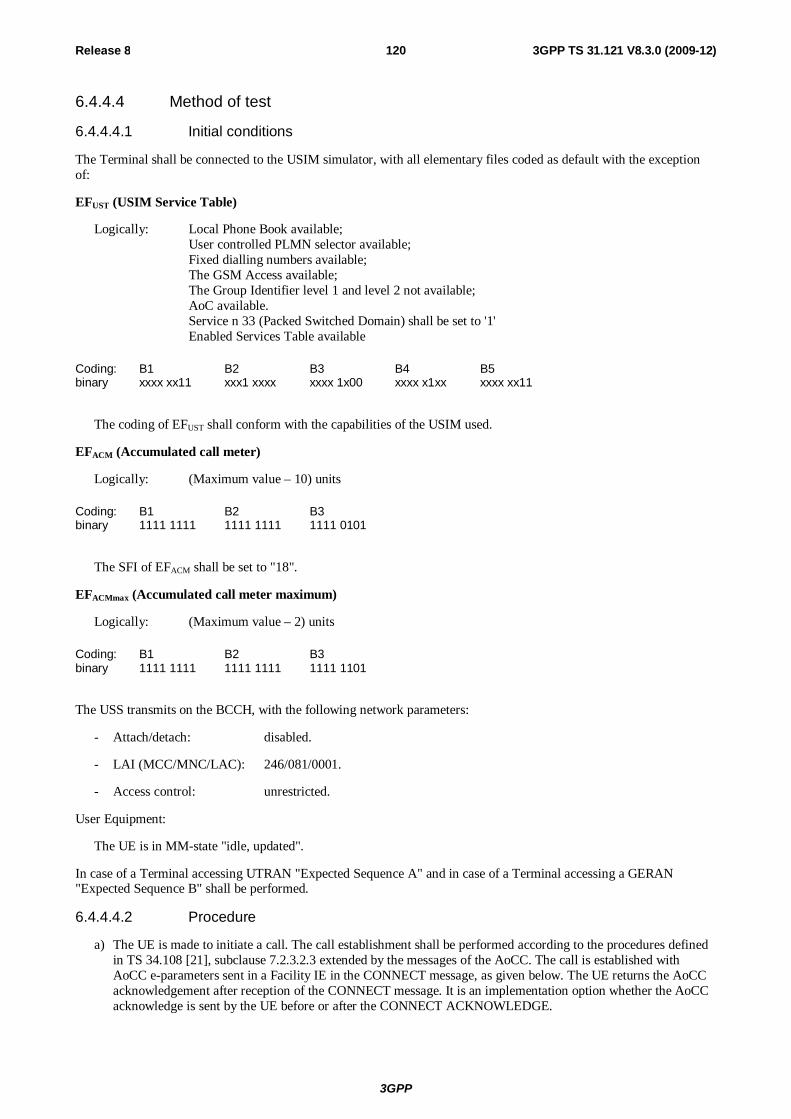
3GPP
Release 8 120 3GPP TS 31.121 V8.3.0 (2009-12)
6.4.4.4 Method of test
6.4.4.4.1 Initial conditions
The Terminal shall be connected to the USIM simulator, with all elementary files coded as default with the exception of:
EFUST (USIM Service Table)
Logically: Local Phone Book available; User controlled PLMN selector available; Fixed dialling numbers available; The GSM Access available; The Group Identifier level 1 and level 2 not available; AoC available. Service n 33 (Packed Switched Domain) shall be set to '1'
Enabled Services Table available
Coding: B1 B2 B3 B4 B5 binary xxxx xx11 xxx1 xxxx xxxx 1x00 xxxx x1xx xxxx xx11
The coding of EFUST shall conform with the capabilities of the USIM used.
EFACM (Accumulated call meter)
Logically: (Maximum value – 10) units
Coding: B1 B2 B3 binary 1111 1111 1111 1111 1111 0101
The SFI of EFACM shall be set to "18".
EFACMmax (Accumulated call meter maximum)
Logically: (Maximum value – 2) units
Coding: B1 B2 B3 binary 1111 1111 1111 1111 1111 1101
The USS transmits on the BCCH, with the following network parameters:
- Attach/detach: disabled.
- LAI (MCC/MNC/LAC): 246/081/0001.
- Access control: unrestricted.
User Equipment:
The UE is in MM-state "idle, updated".
In case of a Terminal accessing UTRAN "Expected Sequence A" and in case of a Terminal accessing a GERAN "Expected Sequence B" shall be performed.
6.4.4.4.2 Procedure
a) The UE is made to initiate a call. The call establishment shall be performed according to the procedures defined in TS 34.108 [21], subclause 7.2.3.2.3 extended by the messages of the AoCC. The call is established with AoCC e-parameters sent in a Facility IE in the CONNECT message, as given below. The UE returns the AoCC acknowledgement after reception of the CONNECT message. It is an implementation option whether the AoCC acknowledge is sent by the UE before or after the CONNECT ACKNOWLEDGE.
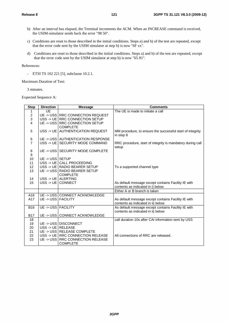
3GPP
Release 8 121 3GPP TS 31.121 V8.3.0 (2009-12)
b) After an interval has elapsed, the Terminal increments the ACM. When an INCREASE command is received, the USIM-simulator sends back the error "98 50".
c) Conditions are reset to those described in the initial conditions. Steps a) and b) of the test are repeated, except that the error code sent by the USIM simulator at step b) is now "6F xx".
d) Conditions are reset to those described in the initial conditions. Steps a) and b) of the test are repeated, except that the error code sent by the USIM simulator at step b) is now "65 81".
References:
- ETSI TS 102 221 [5], subclause 10.2.1.
Maximum Duration of Test:
3 minutes.
Expected Sequence A:
Step Direction Message Comments 1 UE The UE is made to initiate a call 2 UE -> USS RRC CONNECTION REQUEST 3 USS -> UE RRC CONNECTION SETUP 4 UE -> USS RRC CONNECTION SETUP
COMPLETE
5 USS -> UE AUTHENTICATION REQUEST MM procedure, to ensure the successful start of integrity in step 8
6 UE -> USS AUTHENTICATION RESPONSE 7 USS -> UE SECURITY MODE COMMAND RRC procedure, start of integrity is mandatory during call
setup 8 UE -> USS SECURITY MODE COMPLETE 9 10 UE -> USS SETUP 11 USS -> UE CALL PROCEEDING 12 USS -> UE RADIO BEARER SETUP To a supported channel type 13 UE -> USS RADIO BEARER SETUP
COMPLETE
14 USS -> UE ALERTING 15 USS -> UE CONNECT As default message except contains Facility IE with
contents as indicated in i) below Either A or B branch is taken
A16 UE -> USS CONNECT ACKNOWLEDGE A17 UE -> USS FACILITY As default message except contains Facility IE with
contents as indicated in ii) below B16 UE -> USS FACILITY As default message except contains Facility IE with
contents as indicated in ii) below B17 UE -> USS CONNECT ACKNOWLEDGE 18 call duration 10s after CAI information sent by USS 19 UE -> USS DISCONNECT 20 USS -> UE RELEASE 21 UE -> USS RELEASE COMPLETE 22 USS -> UE RRC CONNECTION RELEASE All connections of RRC are released. 23 UE -> USS RRC CONNECTION RELEASE
COMPLETE
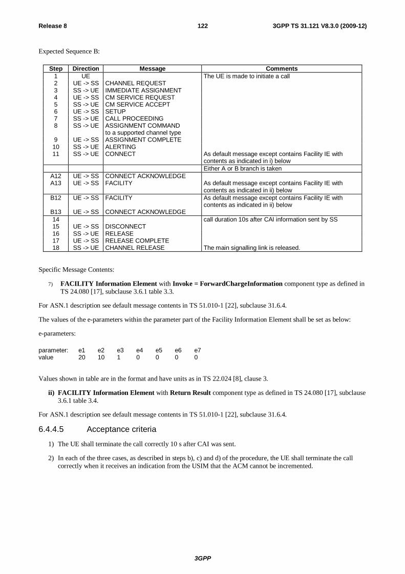
3GPP
Release 8 122 3GPP TS 31.121 V8.3.0 (2009-12)
Expected Sequence B:
Step Direction Message Comments 1 UE The UE is made to initiate a call 2 UE -> SS CHANNEL REQUEST 3 SS -> UE IMMEDIATE ASSIGNMENT 4 UE -> SS CM SERVICE REQUEST 5 SS -> UE CM SERVICE ACCEPT 6 UE -> SS SETUP 7 SS -> UE CALL PROCEEDING 8 SS -> UE ASSIGNMENT COMMAND to a supported channel type
9 UE -> SS ASSIGNMENT COMPLETE 10 SS -> UE ALERTING 11 SS -> UE CONNECT As default message except contains Facility IE with
contents as indicated in i) below Either A or B branch is taken
A12 UE -> SS CONNECT ACKNOWLEDGE A13 UE -> SS FACILITY As default message except contains Facility IE with
contents as indicated in ii) below B12 UE -> SS FACILITY As default message except contains Facility IE with
contents as indicated in ii) below B13 UE -> SS CONNECT ACKNOWLEDGE 14 call duration 10s after CAI information sent by SS 15 UE -> SS DISCONNECT 16 SS -> UE RELEASE 17 UE -> SS RELEASE COMPLETE 18 SS -> UE CHANNEL RELEASE The main signalling link is released.
Specific Message Contents:
7) FACILITY Information Element with Invoke = ForwardChargeInformation component type as defined in TS 24.080 [17], subclause 3.6.1 table 3.3.
For ASN.1 description see default message contents in TS 51.010-1 [22], subclause 31.6.4.
The values of the e-parameters within the parameter part of the Facility Information Element shall be set as below:
e-parameters:
parameter: e1 e2 e3 e4 e5 e6 e7 value 20 10 1 0 0 0 0
Values shown in table are in the format and have units as in TS 22.024 [8], clause 3.
ii) FACILITY Information Element with Return Result component type as defined in TS 24.080 [17], subclause 3.6.1 table 3.4.
For ASN.1 description see default message contents in TS 51.010-1 [22], subclause 31.6.4.
6.4.4.5 Acceptance criteria
1) The UE shall terminate the call correctly 10 s after CAI was sent.
2) In each of the three cases, as described in steps b), c) and d) of the procedure, the UE shall terminate the call correctly when it receives an indication from the USIM that the ACM cannot be incremented.
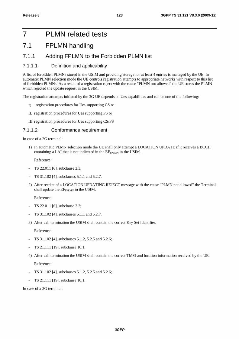
3GPP
Release 8 123 3GPP TS 31.121 V8.3.0 (2009-12)
7 PLMN related tests 7.1 FPLMN handling 7.1.1 Adding FPLMN to the Forbidden PLMN list
7.1.1.1 Definition and applicability
A list of forbidden PLMNs stored in the USIM and providing storage for at least 4 entries is managed by the UE. In automatic PLMN selection mode the UE controls registration attempts to appropriate networks with respect to this list of forbidden PLMNs. As a result of a registration reject with the cause "PLMN not allowed" the UE stores the PLMN which rejected the update request in the USIM.
The registration attempts initiated by the 3G UE depends on Ues capabilities and can be one of the following:
7) registration procedures for Ues supporting CS or
II. registration procedures for Ues supporting PS or
III. registration procedures for Ues supporting CS/PS
7.1.1.2 Conformance requirement
In case of a 2G terminal:
1) In automatic PLMN selection mode the UE shall only attempt a LOCATION UPDATE if it receives a BCCH containing a LAI that is not indicated in the EFFPLMN in the USIM.
Reference:
- TS 22.011 [6], subclause 2.3;
- TS 31.102 [4], subclauses 5.1.1 and 5.2.7.
2) After receipt of a LOCATION UPDATING REJECT message with the cause "PLMN not allowed" the Terminal shall update the EFFPLMN in the USIM.
Reference:
- TS 22.011 [6], subclause 2.3;
- TS 31.102 [4], subclauses 5.1.1 and 5.2.7.
3) After call termination the USIM shall contain the correct Key Set Identifier.
Reference:
- TS 31.102 [4], subclauses 5.1.2, 5.2.5 and 5.2.6;
- TS 21.111 [19], subclause 10.1.
4) After call termination the USIM shall contain the correct TMSI and location information received by the UE.
Reference:
- TS 31.102 [4], subclauses 5.1.2, 5.2.5 and 5.2.6;
- TS 21.111 [19], subclause 10.1.
In case of a 3G terminal:
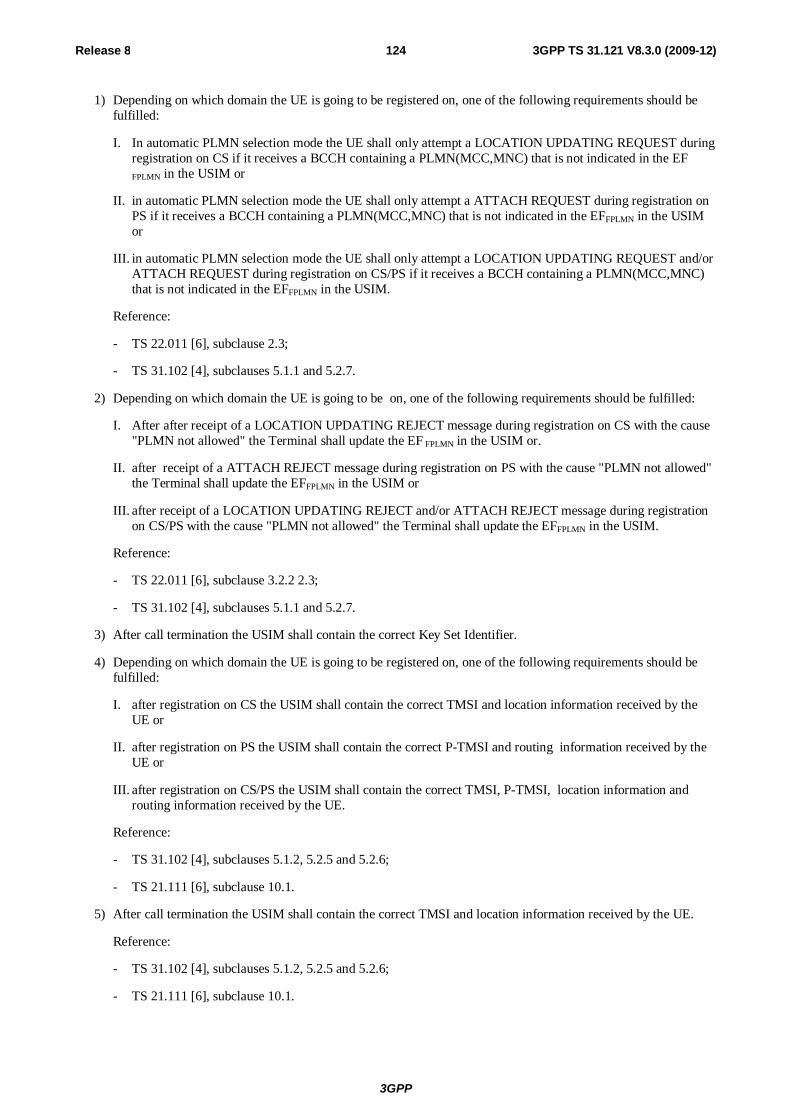
3GPP
Release 8 124 3GPP TS 31.121 V8.3.0 (2009-12)
1) Depending on which domain the UE is going to be registered on, one of the following requirements should be fulfilled:
I. In automatic PLMN selection mode the UE shall only attempt a LOCATION UPDATING REQUEST during registration on CS if it receives a BCCH containing a PLMN(MCC,MNC) that is not indicated in the EF
FPLMN in the USIM or
II. in automatic PLMN selection mode the UE shall only attempt a ATTACH REQUEST during registration on PS if it receives a BCCH containing a PLMN(MCC,MNC) that is not indicated in the EFFPLMN in the USIM or
III. in automatic PLMN selection mode the UE shall only attempt a LOCATION UPDATING REQUEST and/or ATTACH REQUEST during registration on CS/PS if it receives a BCCH containing a PLMN(MCC,MNC) that is not indicated in the EFFPLMN in the USIM.
Reference:
- TS 22.011 [6], subclause 2.3;
- TS 31.102 [4], subclauses 5.1.1 and 5.2.7.
2) Depending on which domain the UE is going to be on, one of the following requirements should be fulfilled:
I. After after receipt of a LOCATION UPDATING REJECT message during registration on CS with the cause "PLMN not allowed" the Terminal shall update the EF FPLMN in the USIM or.
II. after receipt of a ATTACH REJECT message during registration on PS with the cause "PLMN not allowed" the Terminal shall update the EFFPLMN in the USIM or
III. after receipt of a LOCATION UPDATING REJECT and/or ATTACH REJECT message during registration on CS/PS with the cause "PLMN not allowed" the Terminal shall update the EFFPLMN in the USIM.
Reference:
- TS 22.011 [6], subclause 3.2.2 2.3;
- TS 31.102 [4], subclauses 5.1.1 and 5.2.7.
3) After call termination the USIM shall contain the correct Key Set Identifier.
4) Depending on which domain the UE is going to be registered on, one of the following requirements should be fulfilled:
I. after registration on CS the USIM shall contain the correct TMSI and location information received by the UE or
II. after registration on PS the USIM shall contain the correct P-TMSI and routing information received by the UE or
III. after registration on CS/PS the USIM shall contain the correct TMSI, P-TMSI, location information and routing information received by the UE.
Reference:
- TS 31.102 [4], subclauses 5.1.2, 5.2.5 and 5.2.6;
- TS 21.111 [6], subclause 10.1.
5) After call termination the USIM shall contain the correct TMSI and location information received by the UE.
Reference:
- TS 31.102 [4], subclauses 5.1.2, 5.2.5 and 5.2.6;
- TS 21.111 [6], subclause 10.1.

3GPP
Release 8 125 3GPP TS 31.121 V8.3.0 (2009-12)
7.1.1.3 Test purpose
In case of a 2G terminal:
1) To verify that in automatic PLMN selection mode the UE does not attempt to access PLMNs stored in EFFPLMN on the USIM.
2) To verify that the EFFPLMN is correctly updated by the Terminal after receipt of a LOCATION UPDATING REJECT message with cause "PLMN not allowed".
3) To verify that the EFKeys has been correctly updated by the Terminal.
4) To verify that the EFLOCI has been correctly updated by the Terminal.
In case of a 3G terminal:
1) To verify that in automatic PLMN selection mode the UE does not attempt to access PLMNs stored in EFFPLMN on the USIM.
2) To verify that the EFFPLMN is correctly updated by the Terminal after receipt of a
I. LOCATION UPDATING REJECT message with cause "PLMN not allowed" during registration on CS or.
II. ATTACH REJECT message with cause "PLMN not allowed" during registration on PS or.
III. LOCATION UPDATING REJECT and/or ATTACH REJECT message with cause "PLMN not allowed" during registration on CS/PS.
3) To verify that
I. the EFLOCI has been correctly updated by the Terminal during registration on CS or.
II. the EFPSLOCI has been correctly updated by the Terminal during registration on PS or.
III. the the EFLOCI and EFPSLOCI have been correctly updated by the Terminal during registration on CS/PS.
7.1.1.4 Method of test
7.1.1.4.1 Initial conditions
The USS (in case of a Terminal accessing UTRAN)/ SS (in case of a Terminal accessing a GERAN) transmits on the BCCH, with the following network parameters:
- Attach/detach: disabled.
- LAI (MCC/MNC/LAC): 234/002/0001.
- RAI (MCC/MNC/LAC/RAC): 234/002/0001/05. (only for UTRAN cell)
- Access control: unrestricted.
NOTE: In case of a GERAN no packet system information is transmitted
The default UICC is used with the following exception:
EFIMSI (IMSI)
Logically: 246081111111111
Coding: B1 B2 B3 B4 B5 B6 B7 B8 B9 Hex 08 29 64 80 11 11 11 11 11
EFLOCI (Location Information)
Logically: LAI-MCC: 234
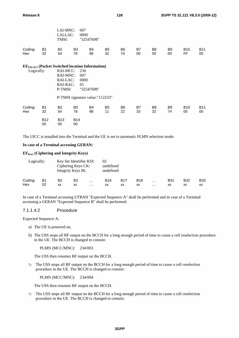
3GPP
Release 8 126 3GPP TS 31.121 V8.3.0 (2009-12)
LAI-MNC: 007 LAI-LAC: 0000 TMSI: "32547698"
Coding: B1 B2 B3 B4 B5 B6 B7 B8 B9 B10 B11 Hex 32 54 76 98 32 74 00 00 00 FF 00
EFPSLOCI (Packet Switched location Information) Logically: RAI-MCC: 234 RAI-MNC: 007 RAI-LAC: 0000 RAI-RAC: 05 P-TMSI: "32547698"
P-TMSI signature value: "112233"
Coding: B1 B2 B3 B4 B5 B6 B7 B8 B9 B10 B11 Hex 32 54 76 98 11 22 33 32 74 00 00 B12 B13 B14 00 05 00
The UICC is installed into the Terminal and the UE is set to automatic PLMN selection mode.
In case of a Terminal accessing GERAN:
EFKeys (Ciphering and Integrity Keys)
Logically: Key Set Identifier KSI: 02 Ciphering Keys CK: undefined Integrity Keys IK: undefined
Coding: B1 B2 B3 … B16 B17 B18 … B31 B32 B33 Hex 02 xx xx … xx xx xx … xx xx xx
In case of a Terminal accessing UTRAN "Expected Sequence A" shall be performed and in case of a Terminal accessing a GERAN "Expected Sequence B" shall be performed.
7.1.1.4.2 Procedure
Expected Sequence A:
a) The UE is powered on.
b) The USS stops all RF output on the BCCH for a long enough period of time to cause a cell reselection procedure in the UE. The BCCH is changed to contain:
PLMN (MCC/MNC): 234/003
The USS then resumes RF output on the BCCH.
7) The USS stops all RF output on the BCCH for a long enough period of time to cause a cell reselection procedure in the UE. The BCCH is changed to contain:
PLMN (MCC/MNC): 234/004
The USS then resumes RF output on the BCCH.
7) The USS stops all RF output on the BCCH for a long enough period of time to cause a cell reselection procedure in the UE. The BCCH is changed to contain:

3GPP
Release 8 127 3GPP TS 31.121 V8.3.0 (2009-12)
PLMN (MCC/MNC): 234/005
The USS then resumes RF output on the BCCH.
7) The USS stops all RF output on the BCCH for a long enough period of time to cause a cell reselection procedure in the UE. The BCCH is changed to contain:
LAI (MCC/MNC/LAC): 234/007/0001
RAI (MCC/MNC/LAC/RAC): 234/007/0001/05
The USS then resumes RF output on the BCCH.
f) After receipt of a RRC CONNECTION REQUEST from the UE, the USS sends RRC CONNECTION SETUP to the UE, followed by RRC CONNECTION SETUP COMPLETE sent by the UE to the USS.
g) Depending on which domain the UE is going to be registered on, one of the following sequences will be passed through:
I. During registration on CS and after receipt of a LOCATION UPDATING REQUEST from the UE, the USS sends LOCATION UPDATING REJECT to the UE with cause "PLMN Not Allowed", followed by RRC CONNECTION RELEASE, followed by RRC CONNECTION RELEASE COMPLETE sent by the UE to the USS.
II. During registration on PS and after receipt of a ATTACH REQUEST from the UE, the USS sends ATTACH REJECT to the UE with cause "PLMN Not Allowed", followed by RRC CONNECTION RELEASE, followed by RRC CONNECTION RELEASE COMPLETE sent by the UE to the USS or
7) During registration on CS/PS and after receipt of a LOCATION UPDATING REQUEST and/or ATTACH REQUEST from the UE, the USS sends LOCATION UPDATING REJECT and/or ATTACH REJECT to the UE with cause "PLMN Not Allowed", followed by RRC CONNECTION RELEASE, followed by RRC CONNECTION RELEASE COMPLETE sent by the UE to the USS.
The USS stops all RF output on the BCCH for a long enough period of time to cause a cell reselection procedure in the UE. The BCCH is changed to contain:
LAI (MCC/MNC): 234/008/0001
RAI (MCC/MNC/LAC/RAC): 234/008/0001/05
The USS then resumes RF output on the BCCH.
h) After receipt of a RRC CONNECTION REQUEST from the UE, the USS sends RRC CONNECTION SETUP to the UE, followed by RRC CONNECTION SETUP COMPLETE sent by the UE to the USS.
i) Depending on which domain the UE is going to be registered on, one of the following sequences will be passed through:
I. During registration on CS and after receipt of a LOCATION UPDATING REQUEST from the UE, the USS initiates authentication, starts integrity by using the security procedure and sends LOCATION UPDATING ACCEPT with:
LAI (MCC/MNC/LAC): 234/008/0001
TMSI: "43658709"
II. During registration on PS and after receipt of a ATTACH REQUEST from the UE, the USS initiates authentication, starts integrity by using the security procedure and sends ATTACH ACCEPT to the UE with :
RAI (MCC/MNC/LAC/RAC): 234/008/0001/05
P-TMSI: "43658709"
P-TMSI signature value "443322"
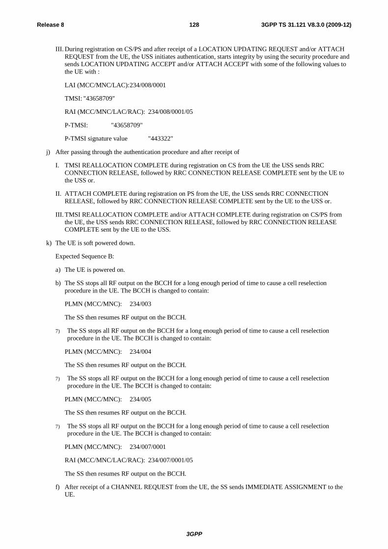
3GPP
Release 8 128 3GPP TS 31.121 V8.3.0 (2009-12)
III. During registration on CS/PS and after receipt of a LOCATION UPDATING REQUEST and/or ATTACH REQUEST from the UE, the USS initiates authentication, starts integrity by using the security procedure and sends LOCATION UPDATING ACCEPT and/or ATTACH ACCEPT with some of the following values to the UE with :
LAI (MCC/MNC/LAC): 234/008/0001
TMSI: "43658709"
RAI (MCC/MNC/LAC/RAC): 234/008/0001/05
P-TMSI: "43658709"
P-TMSI signature value "443322"
j) After passing through the authentication procedure and after receipt of
I. TMSI REALLOCATION COMPLETE during registration on CS from the UE the USS sends RRC CONNECTION RELEASE, followed by RRC CONNECTION RELEASE COMPLETE sent by the UE to the USS or.
II. ATTACH COMPLETE during registration on PS from the UE, the USS sends RRC CONNECTION RELEASE, followed by RRC CONNECTION RELEASE COMPLETE sent by the UE to the USS or.
III. TMSI REALLOCATION COMPLETE and/or ATTACH COMPLETE during registration on CS/PS from the UE, the USS sends RRC CONNECTION RELEASE, followed by RRC CONNECTION RELEASE COMPLETE sent by the UE to the USS.
k) The UE is soft powered down.
Expected Sequence B:
a) The UE is powered on.
b) The SS stops all RF output on the BCCH for a long enough period of time to cause a cell reselection procedure in the UE. The BCCH is changed to contain:
PLMN (MCC/MNC): 234/003
The SS then resumes RF output on the BCCH.
7) The SS stops all RF output on the BCCH for a long enough period of time to cause a cell reselection procedure in the UE. The BCCH is changed to contain:
PLMN (MCC/MNC): 234/004
The SS then resumes RF output on the BCCH.
7) The SS stops all RF output on the BCCH for a long enough period of time to cause a cell reselection procedure in the UE. The BCCH is changed to contain:
PLMN (MCC/MNC): 234/005
The SS then resumes RF output on the BCCH.
7) The SS stops all RF output on the BCCH for a long enough period of time to cause a cell reselection procedure in the UE. The BCCH is changed to contain:
PLMN (MCC/MNC): 234/007/0001
RAI (MCC/MNC/LAC/RAC): 234/007/0001/05
The SS then resumes RF output on the BCCH.
f) After receipt of a CHANNEL REQUEST from the UE, the SS sends IMMEDIATE ASSIGNMENT to the UE.
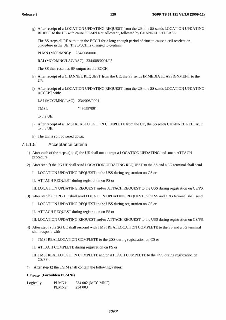
3GPP
Release 8 129 3GPP TS 31.121 V8.3.0 (2009-12)
g) After receipt of a LOCATION UPDATING REQUEST from the UE, the SS sends LOCATION UPDATING REJECT to the UE with cause "PLMN Not Allowed", followed by CHANNEL RELEASE.
The SS stops all RF output on the BCCH for a long enough period of time to cause a cell reselection procedure in the UE. The BCCH is changed to contain:
PLMN (MCC/MNC): 234/008/0001
RAI (MCC/MNC/LAC/RAC): 234/008/0001/05
The SS then resumes RF output on the BCCH.
h) After receipt of a CHANNEL REQUEST from the UE, the SS sends IMMEDIATE ASSIGNMENT to the UE.
i) After receipt of a LOCATION UPDATING REQUEST from the UE, the SS sends LOCATION UPDATING ACCEPT with:
LAI (MCC/MNC/LAC): 234/008/0001
TMSI: "43658709"
to the UE.
j) After receipt of a TMSI REALLOCATION COMPLETE from the UE, the SS sends CHANNEL RELEASE to the UE.
k) The UE is soft powered down.
7.1.1.5 Acceptance criteria
1) After each of the steps a) to d) the UE shall not attempt a LOCATION UPDATING and not a ATTACH procedure.
2) After step f) the 2G UE shall send LOCATION UPDATING REQUEST to the SS and a 3G terminal shall send
I. LOCATION UPDATING REQUEST to the USS during registration on CS or
II. ATTACH REQUEST during registration on PS or
III. LOCATION UPDATING REQUEST and/or ATTACH REQUEST to the USS during registration on CS/PS.
3) After step h) the 2G UE shall send LOCATION UPDATING REQUEST to the SS and a 3G terminal shall send
I. LOCATION UPDATING REQUEST to the USS during registration on CS or
II. ATTACH REQUEST during registration on PS or
III. LOCATION UPDATING REQUEST and/or ATTACH REQUEST to the USS during registration on CS/PS.
4) After step i) the 2G UE shall respond with TMSI REALLOCATION COMPLETE to the SS and a 3G terminal shall respond with
I. TMSI REALLOCATION COMPLETE to the USS during registration on CS or
II. ATTACH COMPLETE during registration on PS or
III. TMSI REALLOCATION COMPLETE and/or ATTACH COMPLETE to the USS during registration on CS/PS..
7) After step k) the USIM shall contain the following values:
EFFPLMN (Forbidden PLMNs)
Logically: PLMN1: 234 002 (MCC MNC) PLMN2: 234 003
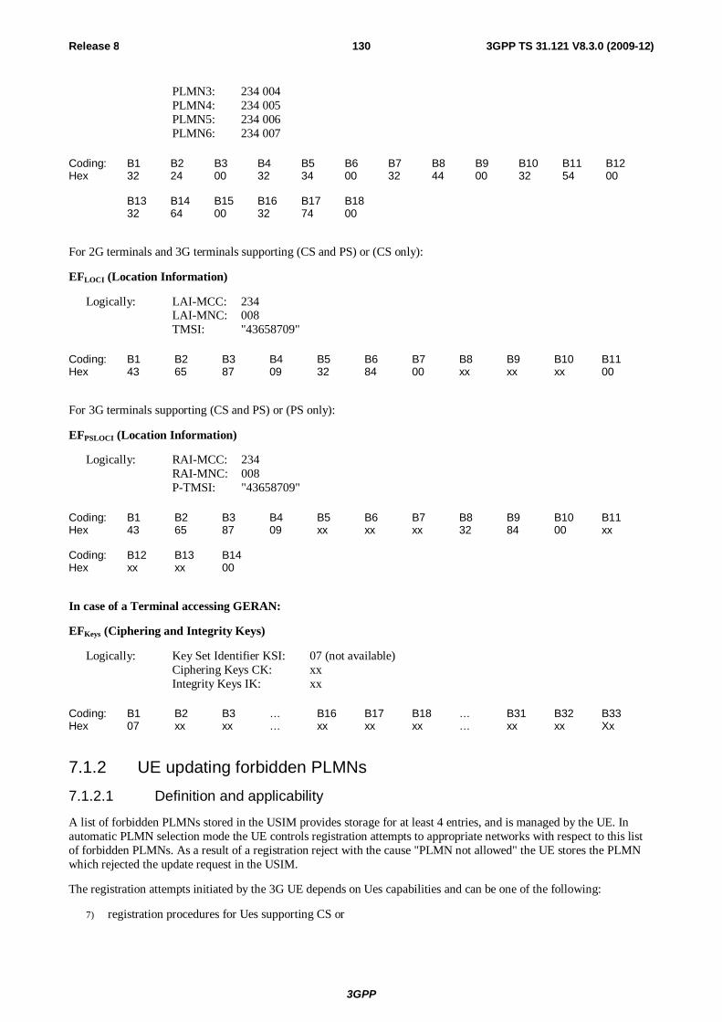
3GPP
Release 8 130 3GPP TS 31.121 V8.3.0 (2009-12)
PLMN3: 234 004 PLMN4: 234 005 PLMN5: 234 006 PLMN6: 234 007
Coding: B1 B2 B3 B4 B5 B6 B7 B8 B9 B10 B11 B12 Hex 32 24 00 32 34 00 32 44 00 32 54 00 B13 B14 B15 B16 B17 B18 32 64 00 32 74 00
For 2G terminals and 3G terminals supporting (CS and PS) or (CS only):
EFLOCI (Location Information)
Logically: LAI-MCC: 234 LAI-MNC: 008 TMSI: "43658709"
Coding: B1 B2 B3 B4 B5 B6 B7 B8 B9 B10 B11 Hex 43 65 87 09 32 84 00 xx xx xx 00
For 3G terminals supporting (CS and PS) or (PS only):
EFPSLOCI (Location Information)
Logically: RAI-MCC: 234 RAI-MNC: 008 P-TMSI: "43658709"
Coding: B1 B2 B3 B4 B5 B6 B7 B8 B9 B10 B11 Hex 43 65 87 09 xx xx xx 32 84 00 xx Coding: B12 B13 B14 Hex xx xx 00
In case of a Terminal accessing GERAN:
EFKeys (Ciphering and Integrity Keys)
Logically: Key Set Identifier KSI: 07 (not available) Ciphering Keys CK: xx Integrity Keys IK: xx
Coding: B1 B2 B3 … B16 B17 B18 … B31 B32 B33 Hex 07 xx xx … xx xx xx … xx xx Xx
7.1.2 UE updating forbidden PLMNs 7.1.2.1 Definition and applicability
A list of forbidden PLMNs stored in the USIM provides storage for at least 4 entries, and is managed by the UE. In automatic PLMN selection mode the UE controls registration attempts to appropriate networks with respect to this list of forbidden PLMNs. As a result of a registration reject with the cause "PLMN not allowed" the UE stores the PLMN which rejected the update request in the USIM.
The registration attempts initiated by the 3G UE depends on Ues capabilities and can be one of the following:
7) registration procedures for Ues supporting CS or
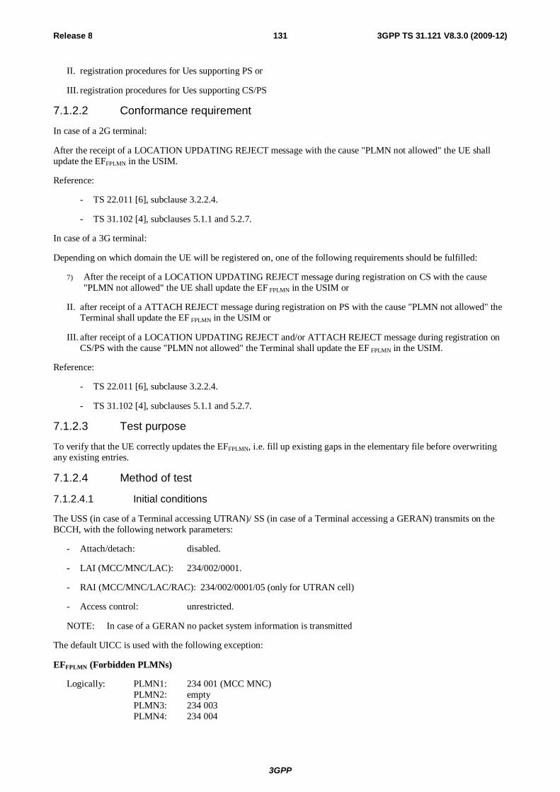
3GPP
Release 8 131 3GPP TS 31.121 V8.3.0 (2009-12)
II. registration procedures for Ues supporting PS or
III. registration procedures for Ues supporting CS/PS
7.1.2.2 Conformance requirement
In case of a 2G terminal:
After the receipt of a LOCATION UPDATING REJECT message with the cause "PLMN not allowed" the UE shall update the EFFPLMN in the USIM.
Reference:
- TS 22.011 [6], subclause 3.2.2.4.
- TS 31.102 [4], subclauses 5.1.1 and 5.2.7.
In case of a 3G terminal:
Depending on which domain the UE will be registered on, one of the following requirements should be fulfilled:
7) After the receipt of a LOCATION UPDATING REJECT message during registration on CS with the cause "PLMN not allowed" the UE shall update the EF FPLMN in the USIM or
II. after receipt of a ATTACH REJECT message during registration on PS with the cause "PLMN not allowed" the Terminal shall update the EF FPLMN in the USIM or
III. after receipt of a LOCATION UPDATING REJECT and/or ATTACH REJECT message during registration on CS/PS with the cause "PLMN not allowed" the Terminal shall update the EF FPLMN in the USIM.
Reference:
- TS 22.011 [6], subclause 3.2.2.4.
- TS 31.102 [4], subclauses 5.1.1 and 5.2.7.
7.1.2.3 Test purpose
To verify that the UE correctly updates the EFFPLMN, i.e. fill up existing gaps in the elementary file before overwriting any existing entries.
7.1.2.4 Method of test
7.1.2.4.1 Initial conditions
The USS (in case of a Terminal accessing UTRAN)/ SS (in case of a Terminal accessing a GERAN) transmits on the BCCH, with the following network parameters:
- Attach/detach: disabled.
- LAI (MCC/MNC/LAC): 234/002/0001.
- RAI (MCC/MNC/LAC/RAC): 234/002/0001/05 (only for UTRAN cell)
- Access control: unrestricted.
NOTE: In case of a GERAN no packet system information is transmitted
The default UICC is used with the following exception:
EFFPLMN (Forbidden PLMNs)
Logically: PLMN1: 234 001 (MCC MNC) PLMN2: empty PLMN3: 234 003 PLMN4: 234 004
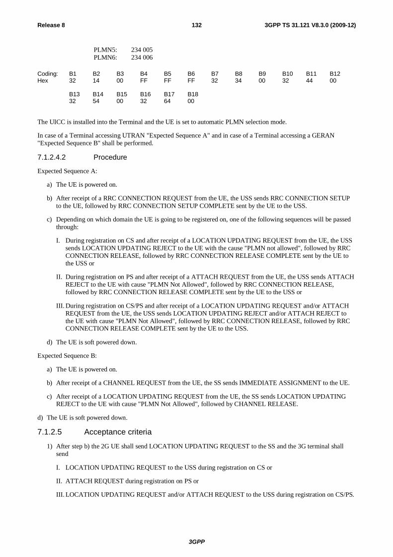
3GPP
Release 8 132 3GPP TS 31.121 V8.3.0 (2009-12)
PLMN5: 234 005 PLMN6: 234 006
Coding: B1 B2 B3 B4 B5 B6 B7 B8 B9 B10 B11 B12 Hex 32 14 00 FF FF FF 32 34 00 32 44 00 B13 B14 B15 B16 B17 B18 32 54 00 32 64 00
The UICC is installed into the Terminal and the UE is set to automatic PLMN selection mode.
In case of a Terminal accessing UTRAN "Expected Sequence A" and in case of a Terminal accessing a GERAN "Expected Sequence B" shall be performed.
7.1.2.4.2 Procedure
Expected Sequence A:
a) The UE is powered on.
b) After receipt of a RRC CONNECTION REQUEST from the UE, the USS sends RRC CONNECTION SETUP to the UE, followed by RRC CONNECTION SETUP COMPLETE sent by the UE to the USS.
c) Depending on which domain the UE is going to be registered on, one of the following sequences will be passed through:
I. During registration on CS and after receipt of a LOCATION UPDATING REQUEST from the UE, the USS sends LOCATION UPDATING REJECT to the UE with the cause "PLMN not allowed", followed by RRC CONNECTION RELEASE, followed by RRC CONNECTION RELEASE COMPLETE sent by the UE to the USS or
II. During registration on PS and after receipt of a ATTACH REQUEST from the UE, the USS sends ATTACH REJECT to the UE with cause "PLMN Not Allowed", followed by RRC CONNECTION RELEASE, followed by RRC CONNECTION RELEASE COMPLETE sent by the UE to the USS or
III. During registration on CS/PS and after receipt of a LOCATION UPDATING REQUEST and/or ATTACH REQUEST from the UE, the USS sends LOCATION UPDATING REJECT and/or ATTACH REJECT to the UE with cause "PLMN Not Allowed", followed by RRC CONNECTION RELEASE, followed by RRC CONNECTION RELEASE COMPLETE sent by the UE to the USS.
d) The UE is soft powered down.
Expected Sequence B:
a) The UE is powered on.
b) After receipt of a CHANNEL REQUEST from the UE, the SS sends IMMEDIATE ASSIGNMENT to the UE.
c) After receipt of a LOCATION UPDATING REQUEST from the UE, the SS sends LOCATION UPDATING REJECT to the UE with cause "PLMN Not Allowed", followed by CHANNEL RELEASE.
d) The UE is soft powered down.
7.1.2.5 Acceptance criteria
1) After step b) the 2G UE shall send LOCATION UPDATING REQUEST to the SS and the 3G terminal shall send
I. LOCATION UPDATING REQUEST to the USS during registration on CS or
II. ATTACH REQUEST during registration on PS or
III. LOCATION UPDATING REQUEST and/or ATTACH REQUEST to the USS during registration on CS/PS.
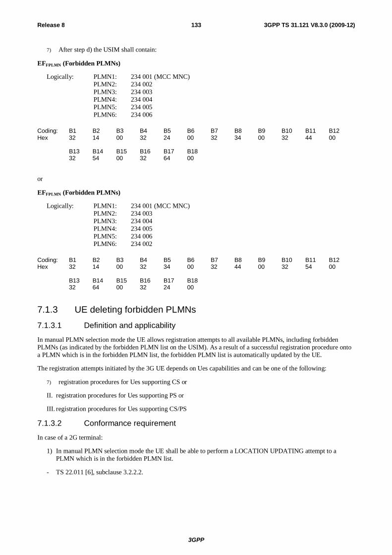
3GPP
Release 8 133 3GPP TS 31.121 V8.3.0 (2009-12)
7) After step d) the USIM shall contain:
EFFPLMN (Forbidden PLMNs)
Logically: PLMN1: 234 001 (MCC MNC) PLMN2: 234 002 PLMN3: 234 003 PLMN4: 234 004 PLMN5: 234 005 PLMN6: 234 006
Coding: B1 B2 B3 B4 B5 B6 B7 B8 B9 B10 B11 B12 Hex 32 14 00 32 24 00 32 34 00 32 44 00 B13 B14 B15 B16 B17 B18 32 54 00 32 64 00
or
EFFPLMN (Forbidden PLMNs)
Logically: PLMN1: 234 001 (MCC MNC) PLMN2: 234 003 PLMN3: 234 004 PLMN4: 234 005 PLMN5: 234 006 PLMN6: 234 002
Coding: B1 B2 B3 B4 B5 B6 B7 B8 B9 B10 B11 B12 Hex 32 14 00 32 34 00 32 44 00 32 54 00 B13 B14 B15 B16 B17 B18 32 64 00 32 24 00
7.1.3 UE deleting forbidden PLMNs
7.1.3.1 Definition and applicability
In manual PLMN selection mode the UE allows registration attempts to all available PLMNs, including forbidden PLMNs (as indicated by the forbidden PLMN list on the USIM). As a result of a successful registration procedure onto a PLMN which is in the forbidden PLMN list, the forbidden PLMN list is automatically updated by the UE.
The registration attempts initiated by the 3G UE depends on Ues capabilities and can be one of the following:
7) registration procedures for Ues supporting CS or
II. registration procedures for Ues supporting PS or
III. registration procedures for Ues supporting CS/PS
7.1.3.2 Conformance requirement
In case of a 2G terminal:
1) In manual PLMN selection mode the UE shall be able to perform a LOCATION UPDATING attempt to a PLMN which is in the forbidden PLMN list.
- TS 22.011 [6], subclause 3.2.2.2.
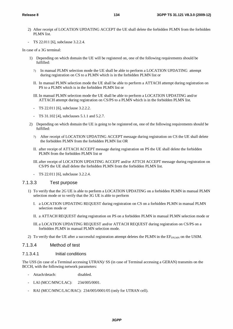
3GPP
Release 8 134 3GPP TS 31.121 V8.3.0 (2009-12)
2) After receipt of LOCATION UPDATING ACCEPT the UE shall delete the forbidden PLMN from the forbidden PLMN list.
- TS 22.011 [6], subclause 3.2.2.4.
In case of a 3G terminal:
1) Depending on which domain the UE will be registered on, one of the following requirements should be fulfilled:
7) In manual PLMN selection mode the UE shall be able to perform a LOCATION UPDATING attempt during registration on CS to a PLMN which is in the forbidden PLMN list or
II. In manual PLMN selection mode the UE shall be able to perform a ATTACH attempt during registration on PS to a PLMN which is in the forbidden PLMN list or
III. In manual PLMN selection mode the UE shall be able to perform a LOCATION UPDATING and/or ATTACH attempt during registration on CS/PS to a PLMN which is in the forbidden PLMN list.
- TS 22.011 [6], subclause 3.2.2.2.
- TS 31.102 [4], subclauses 5.1.1 and 5.2.7.
2) Depending on which domain the UE is going to be registered on, one of the following requirements should be fulfilled:
7) After receipt of LOCATION UPDATING ACCEPT message during registration on CS the UE shall delete the forbidden PLMN from the forbidden PLMN list OR
II. after receipt of ATTACH ACCEPT message during registration on PS the UE shall delete the forbidden PLMN from the forbidden PLMN list or
III. after receipt of LOCATION UPDATING ACCEPT and/or ATTCH ACCEPT message during registration on CS/PS the UE shall delete the forbidden PLMN from the forbidden PLMN list.
- TS 22.011 [6], subclause 3.2.2.4.
7.1.3.3 Test purpose
1) To verify that the 2G UE is able to perform a LOCATION UPDATING on a forbidden PLMN in manual PLMN selection mode or to verify that the 3G UE is able to perform
I. a LOCATION UPDATING REQUEST during registration on CS on a forbidden PLMN in manual PLMN selection mode or
II. a ATTACH REQUEST during registration on PS on a forbidden PLMN in manual PLMN selection mode or
III. a LOCATION UPDATING REQUEST and/or ATTACH REQUEST during registration on CS/PS on a forbidden PLMN in manual PLMN selection mode.
2) To verify that the UE after a successful registration attempt deletes the PLMN in the EFFPLMN on the USIM.
7.1.3.4 Method of test
7.1.3.4.1 Initial conditions
The USS (in case of a Terminal accessing UTRAN)/ SS (in case of Terminal accessing a GERAN) transmits on the BCCH, with the following network parameters:
- Attach/detach: disabled.
- LAI (MCC/MNC/LAC): 234/005/0001.
- RAI (MCC/MNC/LAC/RAC): 234/005/0001/05 (only for UTRAN cell).
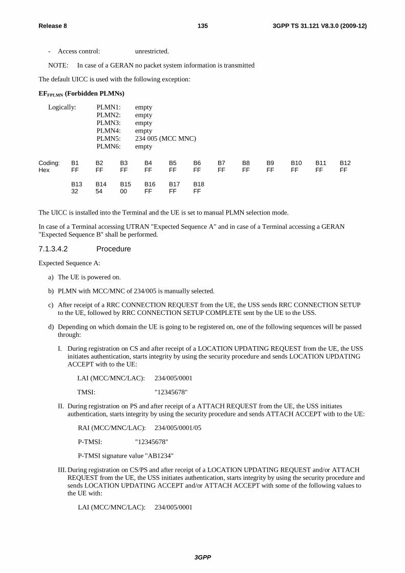
3GPP
Release 8 135 3GPP TS 31.121 V8.3.0 (2009-12)
- Access control: unrestricted.
NOTE: In case of a GERAN no packet system information is transmitted
The default UICC is used with the following exception:
EFFPLMN (Forbidden PLMNs)
Logically: PLMN1: empty PLMN2: empty PLMN3: empty PLMN4: empty PLMN5: 234 005 (MCC MNC) PLMN6: empty
Coding: B1 B2 B3 B4 B5 B6 B7 B8 B9 B10 B11 B12 Hex FF FF FF FF FF FF FF FF FF FF FF FF B13 B14 B15 B16 B17 B18 32 54 00 FF FF FF
The UICC is installed into the Terminal and the UE is set to manual PLMN selection mode.
In case of a Terminal accessing UTRAN "Expected Sequence A" and in case of a Terminal accessing a GERAN "Expected Sequence B" shall be performed.
7.1.3.4.2 Procedure
Expected Sequence A:
a) The UE is powered on.
b) PLMN with MCC/MNC of 234/005 is manually selected.
c) After receipt of a RRC CONNECTION REQUEST from the UE, the USS sends RRC CONNECTION SETUP to the UE, followed by RRC CONNECTION SETUP COMPLETE sent by the UE to the USS.
d) Depending on which domain the UE is going to be registered on, one of the following sequences will be passed through:
I. During registration on CS and after receipt of a LOCATION UPDATING REQUEST from the UE, the USS initiates authentication, starts integrity by using the security procedure and sends LOCATION UPDATING ACCEPT with to the UE:
LAI (MCC/MNC/LAC): 234/005/0001
TMSI: "12345678"
II. During registration on PS and after receipt of a ATTACH REQUEST from the UE, the USS initiates authentication, starts integrity by using the security procedure and sends ATTACH ACCEPT with to the UE:
RAI (MCC/MNC/LAC): 234/005/0001/05
P-TMSI: "12345678"
P-TMSI signature value "AB1234"
III. During registration on CS/PS and after receipt of a LOCATION UPDATING REQUEST and/or ATTACH REQUEST from the UE, the USS initiates authentication, starts integrity by using the security procedure and sends LOCATION UPDATING ACCEPT and/or ATTACH ACCEPT with some of the following values to the UE with:
LAI (MCC/MNC/LAC): 234/005/0001
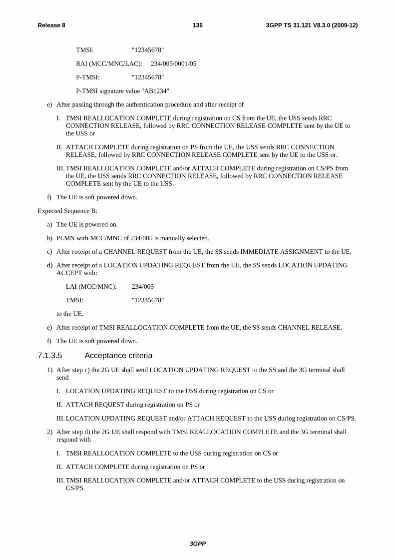
3GPP
Release 8 136 3GPP TS 31.121 V8.3.0 (2009-12)
TMSI: "12345678"
RAI (MCC/MNC/LAC): 234/005/0001/05
P-TMSI: "12345678"
P-TMSI signature value "AB1234"
e) After passing through the authentication procedure and after receipt of
I. TMSI REALLOCATION COMPLETE during registration on CS from the UE, the USS sends RRC CONNECTION RELEASE, followed by RRC CONNECTION RELEASE COMPLETE sent by the UE to the USS or
II. ATTACH COMPLETE during registration on PS from the UE, the USS sends RRC CONNECTION RELEASE, followed by RRC CONNECTION RELEASE COMPLETE sent by the UE to the USS or.
III. TMSI REALLOCATION COMPLETE and/or ATTACH COMPLETE during registration on CS/PS from the UE, the USS sends RRC CONNECTION RELEASE, followed by RRC CONNECTION RELEASE COMPLETE sent by the UE to the USS.
f) The UE is soft powered down.
Expected Sequence B:
a) The UE is powered on.
b) PLMN with MCC/MNC of 234/005 is manually selected.
c) After receipt of a CHANNEL REQUEST from the UE, the SS sends IMMEDIATE ASSIGNMENT to the UE.
d) After receipt of a LOCATION UPDATING REQUEST from the UE, the SS sends LOCATION UPDATING ACCEPT with:
LAI (MCC/MNC): 234/005
TMSI: "12345678"
to the UE.
e) After receipt of TMSI REALLOCATION COMPLETE from the UE, the SS sends CHANNEL RELEASE.
f) The UE is soft powered down.
7.1.3.5 Acceptance criteria
1) After step c) the 2G UE shall send LOCATION UPDATING REQUEST to the SS and the 3G terminal shall send
I. LOCATION UPDATING REQUEST to the USS during registration on CS or
II. ATTACH REQUEST during registration on PS or
III. LOCATION UPDATING REQUEST and/or ATTACH REQUEST to the USS during registration on CS/PS.
2) After step d) the 2G UE shall respond with TMSI REALLOCATION COMPLETE and the 3G terminal shall respond with
I. TMSI REALLOCATION COMPLETE to the USS during registration on CS or
II. ATTACH COMPLETE during registration on PS or
III. TMSI REALLOCATION COMPLETE and/or ATTACH COMPLETE to the USS during registration on CS/PS.
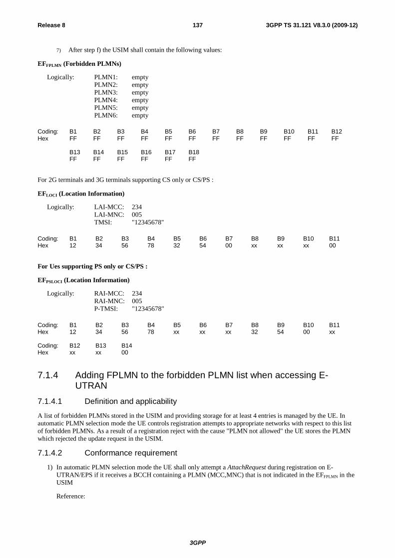
3GPP
Release 8 137 3GPP TS 31.121 V8.3.0 (2009-12)
7) After step f) the USIM shall contain the following values:
EFFPLMN (Forbidden PLMNs)
Logically: PLMN1: empty PLMN2: empty PLMN3: empty PLMN4: empty PLMN5: empty PLMN6: empty
Coding: B1 B2 B3 B4 B5 B6 B7 B8 B9 B10 B11 B12 Hex FF FF FF FF FF FF FF FF FF FF FF FF B13 B14 B15 B16 B17 B18 FF FF FF FF FF FF
For 2G terminals and 3G terminals supporting CS only or CS/PS :
EFLOCI (Location Information)
Logically: LAI-MCC: 234 LAI-MNC: 005 TMSI: "12345678"
Coding: B1 B2 B3 B4 B5 B6 B7 B8 B9 B10 B11 Hex 12 34 56 78 32 54 00 xx xx xx 00
For Ues supporting PS only or CS/PS :
EFPSLOCI (Location Information)
Logically: RAI-MCC: 234 RAI-MNC: 005 P-TMSI: "12345678"
Coding: B1 B2 B3 B4 B5 B6 B7 B8 B9 B10 B11 Hex 12 34 56 78 xx xx xx 32 54 00 xx Coding: B12 B13 B14 Hex xx xx 00
7.1.4 Adding FPLMN to the forbidden PLMN list when accessing E-UTRAN
7.1.4.1 Definition and applicability
A list of forbidden PLMNs stored in the USIM and providing storage for at least 4 entries is managed by the UE. In automatic PLMN selection mode the UE controls registration attempts to appropriate networks with respect to this list of forbidden PLMNs. As a result of a registration reject with the cause "PLMN not allowed" the UE stores the PLMN which rejected the update request in the USIM.
7.1.4.2 Conformance requirement
1) In automatic PLMN selection mode the UE shall only attempt a AttachRequest during registration on E-UTRAN/EPS if it receives a BCCH containing a PLMN (MCC,MNC) that is not indicated in the EFFPLMN in the USIM
Reference:
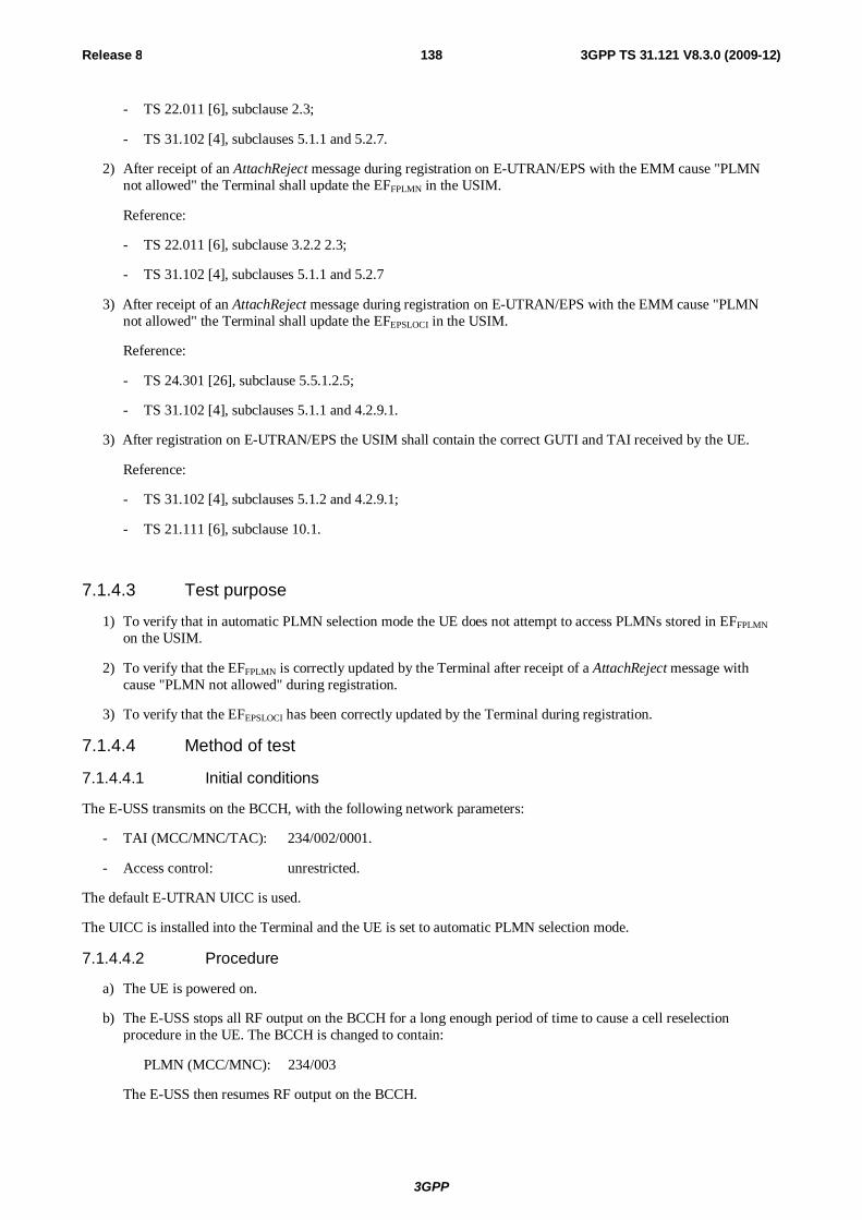
3GPP
Release 8 138 3GPP TS 31.121 V8.3.0 (2009-12)
- TS 22.011 [6], subclause 2.3;
- TS 31.102 [4], subclauses 5.1.1 and 5.2.7.
2) After receipt of an AttachReject message during registration on E-UTRAN/EPS with the EMM cause "PLMN not allowed" the Terminal shall update the EFFPLMN in the USIM.
Reference:
- TS 22.011 [6], subclause 3.2.2 2.3;
- TS 31.102 [4], subclauses 5.1.1 and 5.2.7
3) After receipt of an AttachReject message during registration on E-UTRAN/EPS with the EMM cause "PLMN not allowed" the Terminal shall update the EFEPSLOCI in the USIM.
Reference:
- TS 24.301 [26], subclause 5.5.1.2.5;
- TS 31.102 [4], subclauses 5.1.1 and 4.2.9.1.
3) After registration on E-UTRAN/EPS the USIM shall contain the correct GUTI and TAI received by the UE.
Reference:
- TS 31.102 [4], subclauses 5.1.2 and 4.2.9.1;
- TS 21.111 [6], subclause 10.1.
7.1.4.3 Test purpose
1) To verify that in automatic PLMN selection mode the UE does not attempt to access PLMNs stored in EFFPLMN on the USIM.
2) To verify that the EFFPLMN is correctly updated by the Terminal after receipt of a AttachReject message with cause "PLMN not allowed" during registration.
3) To verify that the EFEPSLOCI has been correctly updated by the Terminal during registration.
7.1.4.4 Method of test
7.1.4.4.1 Initial conditions
The E-USS transmits on the BCCH, with the following network parameters:
- TAI (MCC/MNC/TAC): 234/002/0001.
- Access control: unrestricted.
The default E-UTRAN UICC is used.
The UICC is installed into the Terminal and the UE is set to automatic PLMN selection mode.
7.1.4.4.2 Procedure
a) The UE is powered on.
b) The E-USS stops all RF output on the BCCH for a long enough period of time to cause a cell reselection procedure in the UE. The BCCH is changed to contain:
PLMN (MCC/MNC): 234/003
The E-USS then resumes RF output on the BCCH.
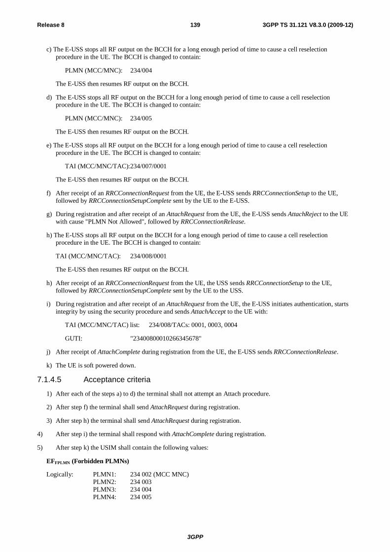
3GPP
Release 8 139 3GPP TS 31.121 V8.3.0 (2009-12)
c) The E-USS stops all RF output on the BCCH for a long enough period of time to cause a cell reselection procedure in the UE. The BCCH is changed to contain:
PLMN (MCC/MNC): 234/004
The E-USS then resumes RF output on the BCCH.
d) The E-USS stops all RF output on the BCCH for a long enough period of time to cause a cell reselection procedure in the UE. The BCCH is changed to contain:
PLMN (MCC/MNC): 234/005
The E-USS then resumes RF output on the BCCH.
e) The E-USS stops all RF output on the BCCH for a long enough period of time to cause a cell reselection procedure in the UE. The BCCH is changed to contain:
TAI (MCC/MNC/TAC): 234/007/0001
The E-USS then resumes RF output on the BCCH.
f) After receipt of an RRCConnectionRequest from the UE, the E-USS sends RRCConnectionSetup to the UE, followed by RRCConnectionSetupComplete sent by the UE to the E-USS.
g) During registration and after receipt of an AttachRequest from the UE, the E-USS sends AttachReject to the UE with cause "PLMN Not Allowed", followed by RRCConnectionRelease.
h) The E-USS stops all RF output on the BCCH for a long enough period of time to cause a cell reselection procedure in the UE. The BCCH is changed to contain:
TAI (MCC/MNC/TAC): 234/008/0001
The E-USS then resumes RF output on the BCCH.
h) After receipt of an RRCConnectionRequest from the UE, the USS sends RRCConnectionSetup to the UE, followed by RRCConnectionSetupComplete sent by the UE to the USS.
i) During registration and after receipt of an AttachRequest from the UE, the E-USS initiates authentication, starts integrity by using the security procedure and sends AttachAccept to the UE with:
TAI (MCC/MNC/TAC) list: 234/008/TACs: 0001, 0003, 0004
GUTI: "23400800010266345678"
j) After receipt of AttachComplete during registration from the UE, the E-USS sends RRCConnectionRelease.
k) The UE is soft powered down.
7.1.4.5 Acceptance criteria
1) After each of the steps a) to d) the terminal shall not attempt an Attach procedure.
2) After step f) the terminal shall send AttachRequest during registration.
3) After step h) the terminal shall send AttachRequest during registration.
4) After step i) the terminal shall respond with AttachComplete during registration.
5) After step k) the USIM shall contain the following values:
EFFPLMN (Forbidden PLMNs)
Logically: PLMN1: 234 002 (MCC MNC) PLMN2: 234 003 PLMN3: 234 004 PLMN4: 234 005
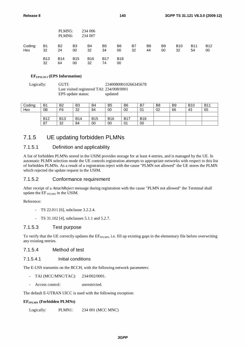
3GPP
Release 8 140 3GPP TS 31.121 V8.3.0 (2009-12)
PLMN5: 234 006 PLMN6: 234 007
Coding: B1 B2 B3 B4 B5 B6 B7 B8 B9 B10 B11 B12 Hex 32 24 00 32 34 00 32 44 00 32 54 00 B13 B14 B15 B16 B17 B18 32 64 00 32 74 00
EFEPSLOCI (EPS Information)
Logically: GUTI: 23400800010266345678 Last visited registered TAI: 234/008/0001 EPS update status: updated
Coding: B1 B2 B3 B4 B5 B6 B7 B8 B9 B10 B11 Hex 0B F6 32 84 00 00 01 02 66 43 65 B12 B13 B14 B15 B16 B17 B18 87 32 84 00 00 01 00
7.1.5 UE updating forbidden PLMNs 7.1.5.1 Definition and applicability
A list of forbidden PLMNs stored in the USIM provides storage for at least 4 entries, and is managed by the UE. In automatic PLMN selection mode the UE controls registration attempts to appropriate networks with respect to this list of forbidden PLMNs. As a result of a registration reject with the cause "PLMN not allowed" the UE stores the PLMN which rejected the update request in the USIM.
7.1.5.2 Conformance requirement
After receipt of a AttachReject message during registration with the cause "PLMN not allowed" the Terminal shall update the EF FPLMN in the USIM.
Reference:
- TS 22.011 [6], subclause 3.2.2.4.
- TS 31.102 [4], subclauses 5.1.1 and 5.2.7.
7.1.5.3 Test purpose
To verify that the UE correctly updates the EFFPLMN, i.e. fill up existing gaps in the elementary file before overwriting any existing entries.
7.1.5.4 Method of test
7.1.5.4.1 Initial conditions
The E-USS transmits on the BCCH, with the following network parameters:
- TAI (MCC/MNC/TAC): 234/002/0001.
- Access control: unrestricted.
The default E-UTRAN UICC is used with the following exception:
EFFPLMN (Forbidden PLMNs)
Logically: PLMN1: 234 001 (MCC MNC)
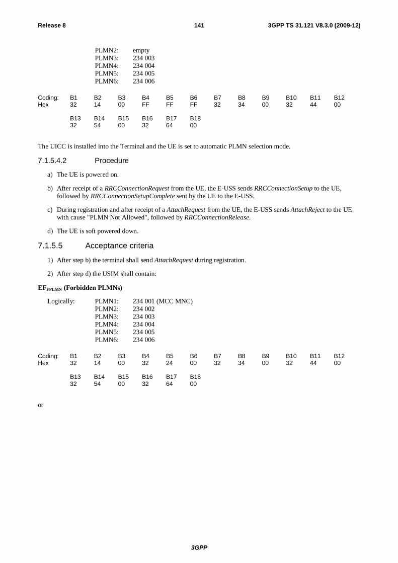
3GPP
Release 8 141 3GPP TS 31.121 V8.3.0 (2009-12)
PLMN2: empty PLMN3: 234 003 PLMN4: 234 004 PLMN5: 234 005 PLMN6: 234 006
Coding: B1 B2 B3 B4 B5 B6 B7 B8 B9 B10 B11 B12 Hex 32 14 00 FF FF FF 32 34 00 32 44 00 B13 B14 B15 B16 B17 B18 32 54 00 32 64 00
The UICC is installed into the Terminal and the UE is set to automatic PLMN selection mode.
7.1.5.4.2 Procedure
a) The UE is powered on.
b) After receipt of a RRCConnectionRequest from the UE, the E-USS sends RRCConnectionSetup to the UE, followed by RRCConnectionSetupComplete sent by the UE to the E-USS.
c) During registration and after receipt of a AttachRequest from the UE, the E-USS sends AttachReject to the UE with cause "PLMN Not Allowed", followed by RRCConnectionRelease.
d) The UE is soft powered down.
7.1.5.5 Acceptance criteria
1) After step b) the terminal shall send AttachRequest during registration.
2) After step d) the USIM shall contain:
EFFPLMN (Forbidden PLMNs)
Logically: PLMN1: 234 001 (MCC MNC) PLMN2: 234 002 PLMN3: 234 003 PLMN4: 234 004 PLMN5: 234 005 PLMN6: 234 006
Coding: B1 B2 B3 B4 B5 B6 B7 B8 B9 B10 B11 B12 Hex 32 14 00 32 24 00 32 34 00 32 44 00 B13 B14 B15 B16 B17 B18 32 54 00 32 64 00
or
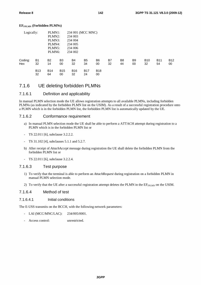
3GPP
Release 8 142 3GPP TS 31.121 V8.3.0 (2009-12)
EFFPLMN (Forbidden PLMNs)
Logically: PLMN1: 234 001 (MCC MNC) PLMN2: 234 003 PLMN3: 234 004 PLMN4: 234 005 PLMN5: 234 006 PLMN6: 234 002
Coding: B1 B2 B3 B4 B5 B6 B7 B8 B9 B10 B11 B12 Hex 32 14 00 32 34 00 32 44 00 32 54 00 B13 B14 B15 B16 B17 B18 32 64 00 32 24 00
7.1.6 UE deleting forbidden PLMNs
7.1.6.1 Definition and applicability
In manual PLMN selection mode the UE allows registration attempts to all available PLMNs, including forbidden PLMNs (as indicated by the forbidden PLMN list on the USIM). As a result of a successful registration procedure onto a PLMN which is in the forbidden PLMN list, the forbidden PLMN list is automatically updated by the UE.
7.1.6.2 Conformance requirement
a) In manual PLMN selection mode the UE shall be able to perform a ATTACH attempt during registration to a PLMN which is in the forbidden PLMN list or
- TS 22.011 [6], subclause 3.2.2.2.
- TS 31.102 [4], subclauses 5.1.1 and 5.2.7.
b) After receipt of AttachAccept message during registration the UE shall delete the forbidden PLMN from the forbidden PLMN list or
- TS 22.011 [6], subclause 3.2.2.4.
7.1.6.3 Test purpose
1) To verify that the terminal is able to perform an AttachRequest during registration on a forbidden PLMN in manual PLMN selection mode.
2) To verify that the UE after a successful registration attempt deletes the PLMN in the EFFPLMN on the USIM.
7.1.6.4 Method of test
7.1.6.4.1 Initial conditions
The E-USS transmits on the BCCH, with the following network parameters:
- LAI (MCC/MNC/LAC): 234/005/0001.
- Access control: unrestricted.

3GPP
Release 8 143 3GPP TS 31.121 V8.3.0 (2009-12)
The default E-UTRAN UICC is used with the following exception:
EFFPLMN (Forbidden PLMNs)
Logically: PLMN1: empty PLMN2: empty PLMN3: empty PLMN4: empty PLMN5: 234 005 (MCC MNC) PLMN6: empty
Coding: B1 B2 B3 B4 B5 B6 B7 B8 B9 B10 B11 B12 Hex FF FF FF FF FF FF FF FF FF FF FF FF B13 B14 B15 B16 B17 B18 32 54 00 FF FF FF
The UICC is installed into the Terminal and the UE is set to manual PLMN selection mode.
7.1.6.4.2 Procedure
a) The UE is powered on.
b) PLMN with MCC/MNC of 234/005 is manually selected.
c) After receipt of a RRCConnectRequest from the UE, the E-USS sends RRCConnectionSetup to the UE, followed by RRCConnectionSetupComplete sent by the UE to the E-USS.
d) During registration and after receipt of a AttachRequest from the UE, the E-USS initiates authentication, starts integrity by using the security procedure and sends AttachAccept with to the UE:
TAI (MCC/MNC/TAC) list: 234/005/TACs: 0001, 0003, 0004
GUTI: "23400500010266345678"
e) After receipt of the AttachComplete during registration from the UE, the E-USS sends RRCConnectionRelease.
f) The UE is soft powered down.
7.1.6.5 Acceptance criteria
1) After step c) the terminal shall send AttachRequest during registration
2) After step d) the terminal shall respond with AttachComplete during registration
3) After step f) the USIM shall contain the following values:
EFFPLMN (Forbidden PLMNs)
Logically: PLMN1: empty PLMN2: empty PLMN3: empty PLMN4: empty PLMN5: empty PLMN6: empty
Coding: B1 B2 B3 B4 B5 B6 B7 B8 B9 B10 B11 B12 Hex FF FF FF FF FF FF FF FF FF FF FF FF B13 B14 B15 B16 B17 B18 FF FF FF FF FF FF
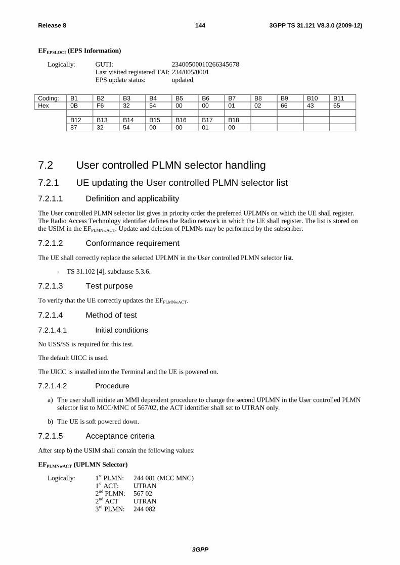
3GPP
Release 8 144 3GPP TS 31.121 V8.3.0 (2009-12)
EFEPSLOCI (EPS Information)
Logically: GUTI: 23400500010266345678 Last visited registered TAI: 234/005/0001 EPS update status: updated
Coding: B1 B2 B3 B4 B5 B6 B7 B8 B9 B10 B11 Hex 0B F6 32 54 00 00 01 02 66 43 65 B12 B13 B14 B15 B16 B17 B18 87 32 54 00 00 01 00
7.2 User controlled PLMN selector handling 7.2.1 UE updating the User controlled PLMN selector list 7.2.1.1 Definition and applicability
The User controlled PLMN selector list gives in priority order the preferred UPLMNs on which the UE shall register. The Radio Access Technology identifier defines the Radio network in which the UE shall register. The list is stored on the USIM in the EFPLMNwACT. Update and deletion of PLMNs may be performed by the subscriber.
7.2.1.2 Conformance requirement
The UE shall correctly replace the selected UPLMN in the User controlled PLMN selector list.
- TS 31.102 [4], subclause 5.3.6.
7.2.1.3 Test purpose
To verify that the UE correctly updates the EFPLMNwACT.
7.2.1.4 Method of test
7.2.1.4.1 Initial conditions
No USS/SS is required for this test.
The default UICC is used.
The UICC is installed into the Terminal and the UE is powered on.
7.2.1.4.2 Procedure
a) The user shall initiate an MMI dependent procedure to change the second UPLMN in the User controlled PLMN selector list to MCC/MNC of 567/02, the ACT identifier shall set to UTRAN only.
b) The UE is soft powered down.
7.2.1.5 Acceptance criteria
After step b) the USIM shall contain the following values:
EFPLMNwACT (UPLMN Selector)
Logically: 1st PLMN: 244 081 (MCC MNC) 1st ACT: UTRAN 2nd PLMN: 567 02 2nd ACT UTRAN 3rd PLMN: 244 082
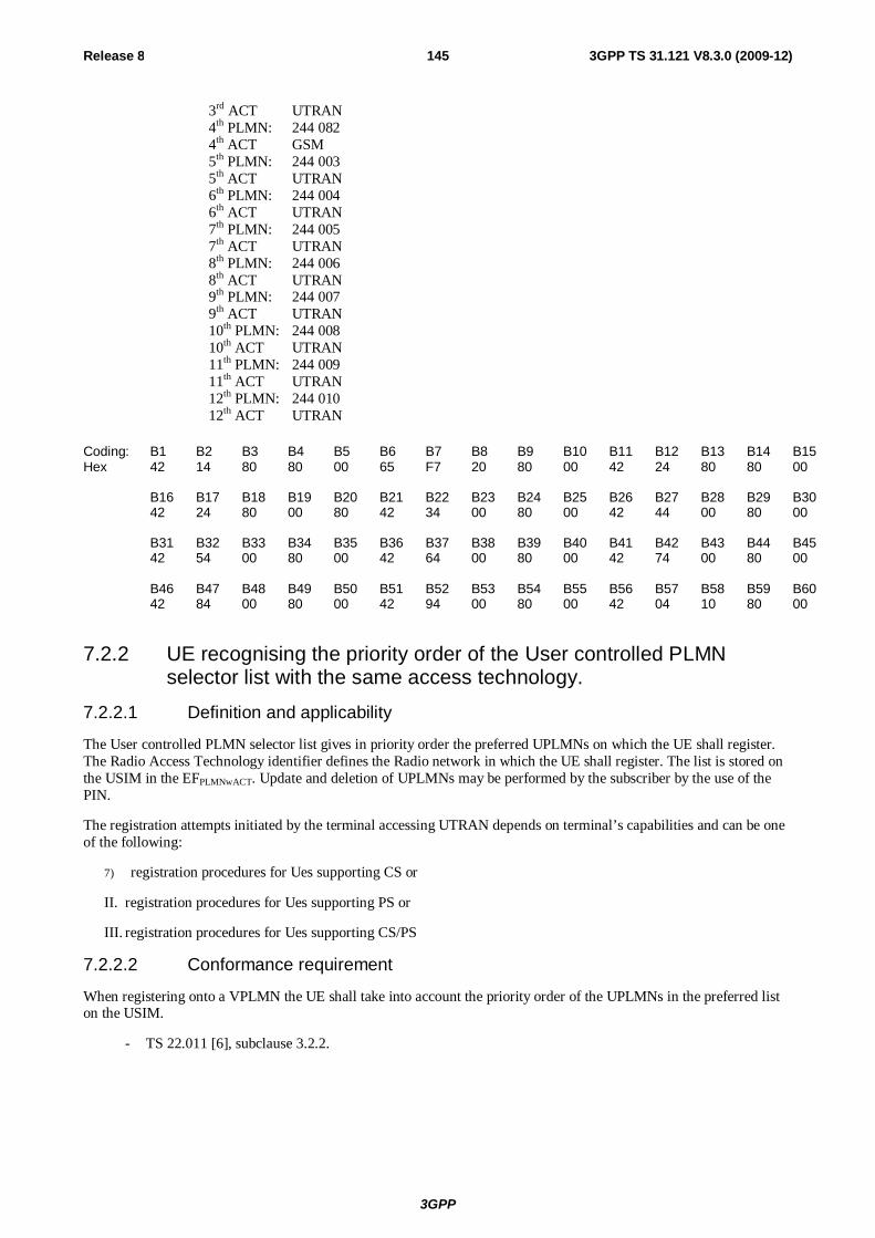
3GPP
Release 8 145 3GPP TS 31.121 V8.3.0 (2009-12)
3rd ACT UTRAN 4th PLMN: 244 082 4th ACT GSM 5th PLMN: 244 003 5th ACT UTRAN 6th PLMN: 244 004 6th ACT UTRAN 7th PLMN: 244 005 7th ACT UTRAN 8th PLMN: 244 006 8th ACT UTRAN 9th PLMN: 244 007 9th ACT UTRAN 10th PLMN: 244 008 10th ACT UTRAN 11th PLMN: 244 009 11th ACT UTRAN 12th PLMN: 244 010 12th ACT UTRAN
Coding: B1 B2 B3 B4 B5 B6 B7 B8 B9 B10 B11 B12 B13 B14 B15 Hex 42 14 80 80 00 65 F7 20 80 00 42 24 80 80 00 B16 B17 B18 B19 B20 B21 B22 B23 B24 B25 B26 B27 B28 B29 B30 42 24 80 00 80 42 34 00 80 00 42 44 00 80 00 B31 B32 B33 B34 B35 B36 B37 B38 B39 B40 B41 B42 B43 B44 B45 42 54 00 80 00 42 64 00 80 00 42 74 00 80 00 B46 B47 B48 B49 B50 B51 B52 B53 B54 B55 B56 B57 B58 B59 B60 42 84 00 80 00 42 94 00 80 00 42 04 10 80 00
7.2.2 UE recognising the priority order of the User controlled PLMN selector list with the same access technology.
7.2.2.1 Definition and applicability
The User controlled PLMN selector list gives in priority order the preferred UPLMNs on which the UE shall register. The Radio Access Technology identifier defines the Radio network in which the UE shall register. The list is stored on the USIM in the EFPLMNwACT. Update and deletion of UPLMNs may be performed by the subscriber by the use of the PIN.
The registration attempts initiated by the terminal accessing UTRAN depends on terminal’s capabilities and can be one of the following:
7) registration procedures for Ues supporting CS or
II. registration procedures for Ues supporting PS or
III. registration procedures for Ues supporting CS/PS
7.2.2.2 Conformance requirement
When registering onto a VPLMN the UE shall take into account the priority order of the UPLMNs in the preferred list on the USIM.
- TS 22.011 [6], subclause 3.2.2.
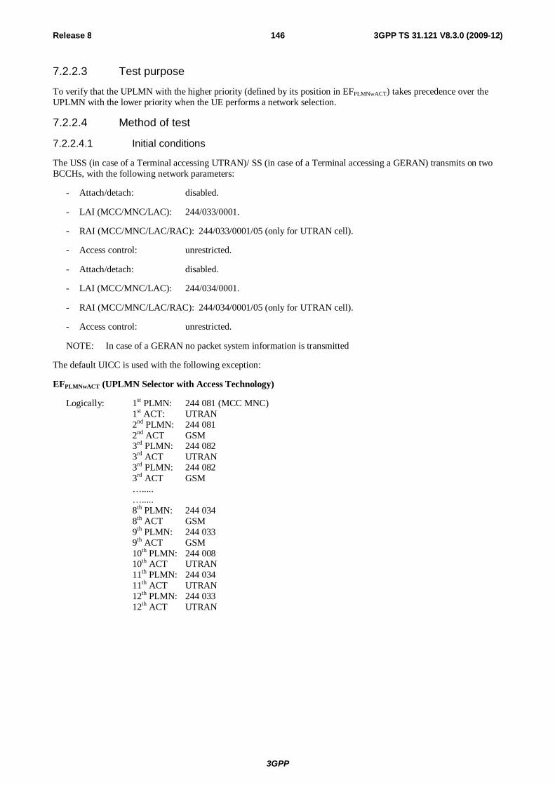
3GPP
Release 8 146 3GPP TS 31.121 V8.3.0 (2009-12)
7.2.2.3 Test purpose
To verify that the UPLMN with the higher priority (defined by its position in EFPLMNwACT) takes precedence over the UPLMN with the lower priority when the UE performs a network selection.
7.2.2.4 Method of test
7.2.2.4.1 Initial conditions
The USS (in case of a Terminal accessing UTRAN)/ SS (in case of a Terminal accessing a GERAN) transmits on two BCCHs, with the following network parameters:
- Attach/detach: disabled.
- LAI (MCC/MNC/LAC): 244/033/0001.
- RAI (MCC/MNC/LAC/RAC): 244/033/0001/05 (only for UTRAN cell).
- Access control: unrestricted.
- Attach/detach: disabled.
- LAI (MCC/MNC/LAC): 244/034/0001.
- RAI (MCC/MNC/LAC/RAC): 244/034/0001/05 (only for UTRAN cell).
- Access control: unrestricted.
NOTE: In case of a GERAN no packet system information is transmitted
The default UICC is used with the following exception:
EFPLMNwACT (UPLMN Selector with Access Technology)
Logically: 1st PLMN: 244 081 (MCC MNC) 1st ACT: UTRAN 2nd PLMN: 244 081 2nd ACT GSM 3rd PLMN: 244 082 3rd ACT UTRAN 3rd PLMN: 244 082 3rd ACT GSM …..... …..... 8th PLMN: 244 034 8th ACT GSM 9th PLMN: 244 033 9th ACT GSM 10th PLMN: 244 008 10th ACT UTRAN 11th PLMN: 244 034 11th ACT UTRAN 12th PLMN: 244 033 12th ACT UTRAN
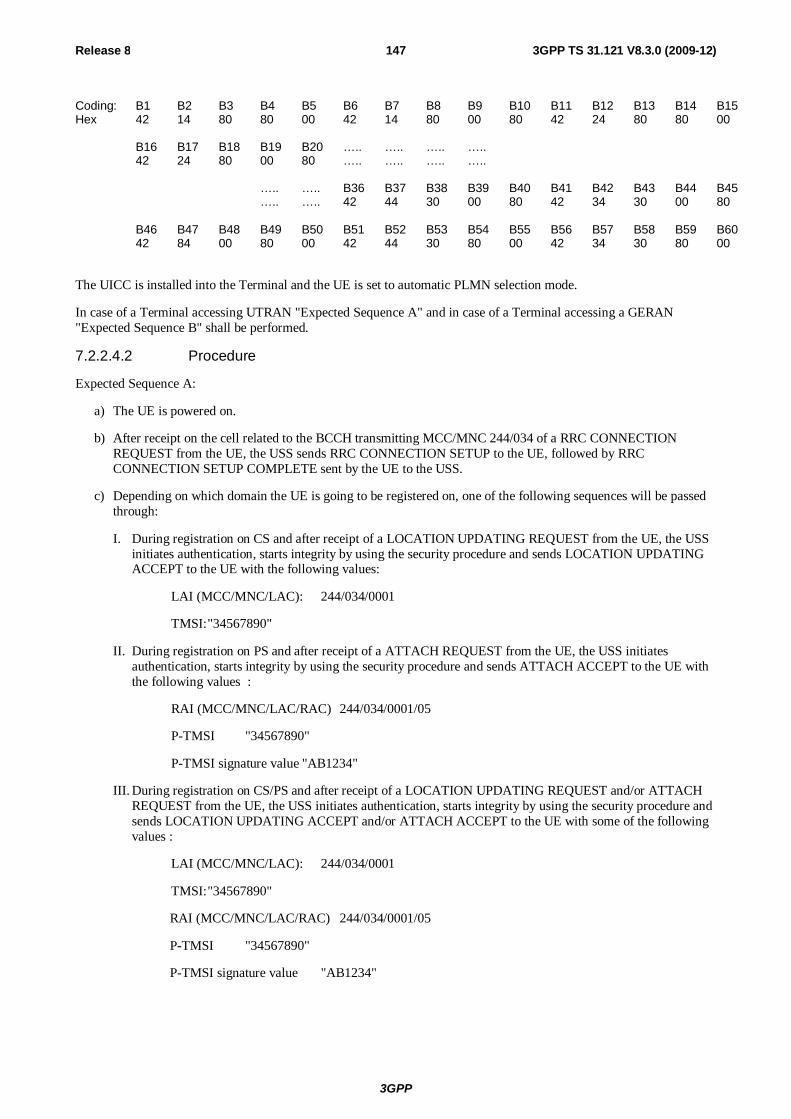
3GPP
Release 8 147 3GPP TS 31.121 V8.3.0 (2009-12)
Coding: B1 B2 B3 B4 B5 B6 B7 B8 B9 B10 B11 B12 B13 B14 B15 Hex 42 14 80 80 00 42 14 80 00 80 42 24 80 80 00 B16 B17 B18 B19 B20 ….. ….. ….. ….. 42 24 80 00 80 ….. ….. ….. ….. ….. ….. B36 B37 B38 B39 B40 B41 B42 B43 B44 B45 ….. ….. 42 44 30 00 80 42 34 30 00 80 B46 B47 B48 B49 B50 B51 B52 B53 B54 B55 B56 B57 B58 B59 B60 42 84 00 80 00 42 44 30 80 00 42 34 30 80 00
The UICC is installed into the Terminal and the UE is set to automatic PLMN selection mode.
In case of a Terminal accessing UTRAN "Expected Sequence A" and in case of a Terminal accessing a GERAN "Expected Sequence B" shall be performed.
7.2.2.4.2 Procedure
Expected Sequence A:
a) The UE is powered on.
b) After receipt on the cell related to the BCCH transmitting MCC/MNC 244/034 of a RRC CONNECTION REQUEST from the UE, the USS sends RRC CONNECTION SETUP to the UE, followed by RRC CONNECTION SETUP COMPLETE sent by the UE to the USS.
c) Depending on which domain the UE is going to be registered on, one of the following sequences will be passed through:
I. During registration on CS and after receipt of a LOCATION UPDATING REQUEST from the UE, the USS initiates authentication, starts integrity by using the security procedure and sends LOCATION UPDATING ACCEPT to the UE with the following values:
LAI (MCC/MNC/LAC): 244/034/0001
TMSI: "34567890"
II. During registration on PS and after receipt of a ATTACH REQUEST from the UE, the USS initiates authentication, starts integrity by using the security procedure and sends ATTACH ACCEPT to the UE with the following values :
RAI (MCC/MNC/LAC/RAC) 244/034/0001/05
P-TMSI "34567890"
P-TMSI signature value "AB1234"
III. During registration on CS/PS and after receipt of a LOCATION UPDATING REQUEST and/or ATTACH REQUEST from the UE, the USS initiates authentication, starts integrity by using the security procedure and sends LOCATION UPDATING ACCEPT and/or ATTACH ACCEPT to the UE with some of the following values :
LAI (MCC/MNC/LAC): 244/034/0001
TMSI: "34567890"
RAI (MCC/MNC/LAC/RAC) 244/034/0001/05
P-TMSI "34567890"
P-TMSI signature value "AB1234"
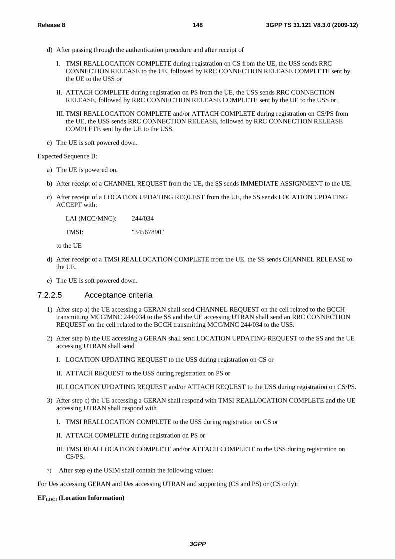
3GPP
Release 8 148 3GPP TS 31.121 V8.3.0 (2009-12)
d) After passing through the authentication procedure and after receipt of
I. TMSI REALLOCATION COMPLETE during registration on CS from the UE, the USS sends RRC CONNECTION RELEASE to the UE, followed by RRC CONNECTION RELEASE COMPLETE sent by the UE to the USS or
II. ATTACH COMPLETE during registration on PS from the UE, the USS sends RRC CONNECTION RELEASE, followed by RRC CONNECTION RELEASE COMPLETE sent by the UE to the USS or.
III. TMSI REALLOCATION COMPLETE and/or ATTACH COMPLETE during registration on CS/PS from the UE, the USS sends RRC CONNECTION RELEASE, followed by RRC CONNECTION RELEASE COMPLETE sent by the UE to the USS.
e) The UE is soft powered down.
Expected Sequence B:
a) The UE is powered on.
b) After receipt of a CHANNEL REQUEST from the UE, the SS sends IMMEDIATE ASSIGNMENT to the UE.
c) After receipt of a LOCATION UPDATING REQUEST from the UE, the SS sends LOCATION UPDATING ACCEPT with:
LAI (MCC/MNC): 244/034
TMSI: "34567890"
to the UE
d) After receipt of a TMSI REALLOCATION COMPLETE from the UE, the SS sends CHANNEL RELEASE to the UE.
e) The UE is soft powered down.
7.2.2.5 Acceptance criteria
1) After step a) the UE accessing a GERAN shall send CHANNEL REQUEST on the cell related to the BCCH transmitting MCC/MNC 244/034 to the SS and the UE accessing UTRAN shall send an RRC CONNECTION REQUEST on the cell related to the BCCH transmitting MCC/MNC 244/034 to the USS.
2) After step b) the UE accessing a GERAN shall send LOCATION UPDATING REQUEST to the SS and the UE accessing UTRAN shall send
I. LOCATION UPDATING REQUEST to the USS during registration on CS or
II. ATTACH REQUEST to the USS during registration on PS or
III. LOCATION UPDATING REQUEST and/or ATTACH REQUEST to the USS during registration on CS/PS.
3) After step c) the UE accessing a GERAN shall respond with TMSI REALLOCATION COMPLETE and the UE accessing UTRAN shall respond with
I. TMSI REALLOCATION COMPLETE to the USS during registration on CS or
II. ATTACH COMPLETE during registration on PS or
III. TMSI REALLOCATION COMPLETE and/or ATTACH COMPLETE to the USS during registration on CS/PS.
7) After step e) the USIM shall contain the following values:
For Ues accessing GERAN and Ues accessing UTRAN and supporting (CS and PS) or (CS only):
EFLOCI (Location Information)
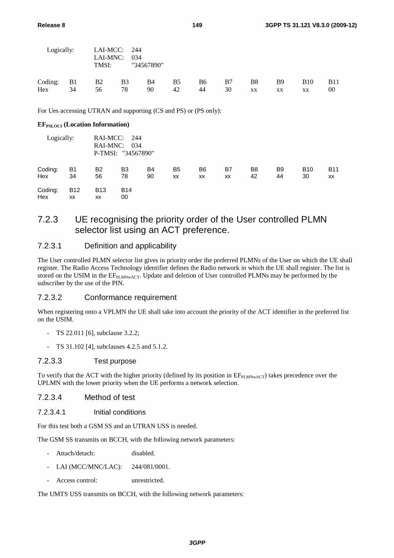
3GPP
Release 8 149 3GPP TS 31.121 V8.3.0 (2009-12)
Logically: LAI-MCC: 244 LAI-MNC: 034 TMSI: "34567890"
Coding: B1 B2 B3 B4 B5 B6 B7 B8 B9 B10 B11 Hex 34 56 78 90 42 44 30 xx xx xx 00
For Ues accessing UTRAN and supporting (CS and PS) or (PS only):
EFPSLOCI (Location Information)
Logically: RAI-MCC: 244 RAI-MNC: 034 P-TMSI: "34567890"
Coding: B1 B2 B3 B4 B5 B6 B7 B8 B9 B10 B11 Hex 34 56 78 90 xx xx xx 42 44 30 xx Coding: B12 B13 B14 Hex xx xx 00
7.2.3 UE recognising the priority order of the User controlled PLMN selector list using an ACT preference.
7.2.3.1 Definition and applicability
The User controlled PLMN selector list gives in priority order the preferred PLMNs of the User on which the UE shall register. The Radio Access Technology identifier defines the Radio network in which the UE shall register. The list is stored on the USIM in the EFPLMNwACT. Update and deletion of User controlled PLMNs may be performed by the subscriber by the use of the PIN.
7.2.3.2 Conformance requirement
When registering onto a VPLMN the UE shall take into account the priority of the ACT identifier in the preferred list on the USIM.
- TS 22.011 [6], subclause 3.2.2;
- TS 31.102 [4], subclauses 4.2.5 and 5.1.2.
7.2.3.3 Test purpose
To verify that the ACT with the higher priority (defined by its position in EFPLMNwACT) takes precedence over the UPLMN with the lower priority when the UE performs a network selection.
7.2.3.4 Method of test
7.2.3.4.1 Initial conditions
For this test both a GSM SS and an UTRAN USS is needed.
The GSM SS transmits on BCCH, with the following network parameters:
- Attach/detach: disabled.
- LAI (MCC/MNC/LAC): 244/081/0001.
- Access control: unrestricted.
The UMTS USS transmits on BCCH, with the following network parameters:
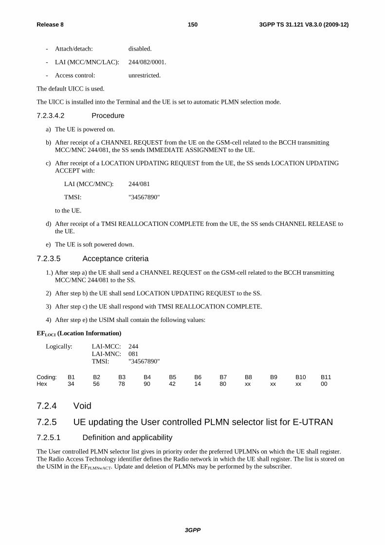
3GPP
Release 8 150 3GPP TS 31.121 V8.3.0 (2009-12)
- Attach/detach: disabled.
- LAI (MCC/MNC/LAC): 244/082/0001.
- Access control: unrestricted.
The default UICC is used.
The UICC is installed into the Terminal and the UE is set to automatic PLMN selection mode.
7.2.3.4.2 Procedure
a) The UE is powered on.
b) After receipt of a CHANNEL REQUEST from the UE on the GSM-cell related to the BCCH transmitting MCC/MNC 244/081, the SS sends IMMEDIATE ASSIGNMENT to the UE.
c) After receipt of a LOCATION UPDATING REQUEST from the UE, the SS sends LOCATION UPDATING ACCEPT with:
LAI (MCC/MNC): 244/081
TMSI: "34567890"
to the UE.
d) After receipt of a TMSI REALLOCATION COMPLETE from the UE, the SS sends CHANNEL RELEASE to the UE.
e) The UE is soft powered down.
7.2.3.5 Acceptance criteria
1.) After step a) the UE shall send a CHANNEL REQUEST on the GSM-cell related to the BCCH transmitting MCC/MNC 244/081 to the SS.
2) After step b) the UE shall send LOCATION UPDATING REQUEST to the SS.
3) After step c) the UE shall respond with TMSI REALLOCATION COMPLETE.
4) After step e) the USIM shall contain the following values:
EFLOCI (Location Information)
Logically: LAI-MCC: 244 LAI-MNC: 081 TMSI: "34567890"
Coding: B1 B2 B3 B4 B5 B6 B7 B8 B9 B10 B11 Hex 34 56 78 90 42 14 80 xx xx xx 00
7.2.4 Void
7.2.5 UE updating the User controlled PLMN selector list for E-UTRAN
7.2.5.1 Definition and applicability
The User controlled PLMN selector list gives in priority order the preferred UPLMNs on which the UE shall register. The Radio Access Technology identifier defines the Radio network in which the UE shall register. The list is stored on the USIM in the EFPLMNwACT. Update and deletion of PLMNs may be performed by the subscriber.
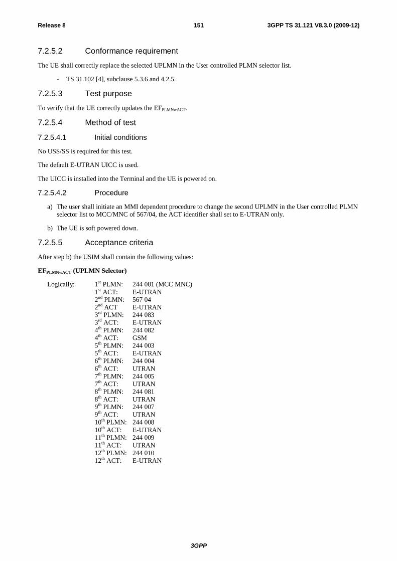
3GPP
Release 8 151 3GPP TS 31.121 V8.3.0 (2009-12)
7.2.5.2 Conformance requirement
The UE shall correctly replace the selected UPLMN in the User controlled PLMN selector list.
- TS 31.102 [4], subclause 5.3.6 and 4.2.5.
7.2.5.3 Test purpose
To verify that the UE correctly updates the EFPLMNwACT.
7.2.5.4 Method of test
7.2.5.4.1 Initial conditions
No USS/SS is required for this test.
The default E-UTRAN UICC is used.
The UICC is installed into the Terminal and the UE is powered on.
7.2.5.4.2 Procedure
a) The user shall initiate an MMI dependent procedure to change the second UPLMN in the User controlled PLMN selector list to MCC/MNC of 567/04, the ACT identifier shall set to E-UTRAN only.
b) The UE is soft powered down.
7.2.5.5 Acceptance criteria
After step b) the USIM shall contain the following values:
EFPLMNwACT (UPLMN Selector)
Logically: 1st PLMN: 244 081 (MCC MNC) 1st ACT: E-UTRAN 2nd PLMN: 567 04 2nd ACT E-UTRAN 3rd PLMN: 244 083 3rd ACT: E-UTRAN 4th PLMN: 244 082 4th ACT: GSM 5th PLMN: 244 003 5th ACT: E-UTRAN 6th PLMN: 244 004 6th ACT: UTRAN 7th PLMN: 244 005 7th ACT: UTRAN 8th PLMN: 244 081 8th ACT: UTRAN 9th PLMN: 244 007 9th ACT: UTRAN 10th PLMN: 244 008 10th ACT: E-UTRAN 11th PLMN: 244 009 11th ACT: UTRAN 12th PLMN: 244 010 12th ACT: E-UTRAN
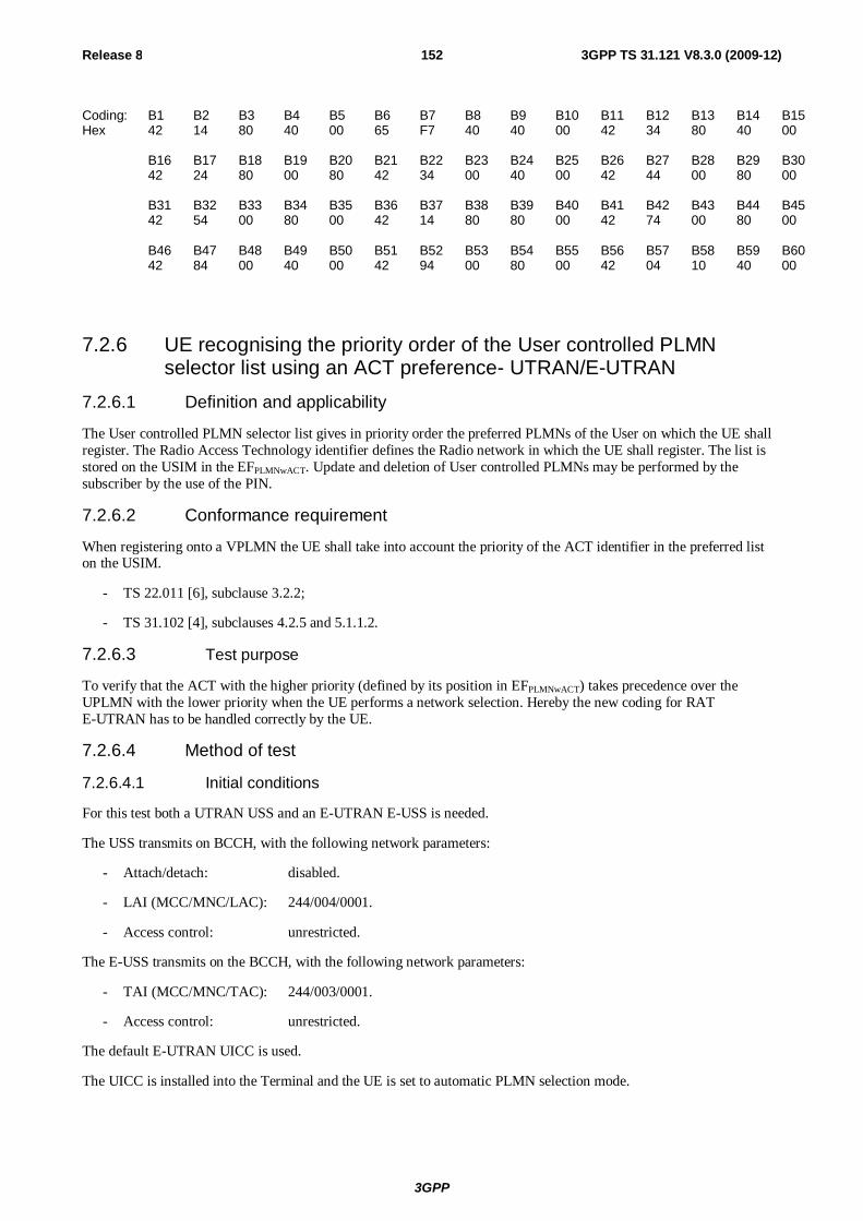
3GPP
Release 8 152 3GPP TS 31.121 V8.3.0 (2009-12)
Coding: B1 B2 B3 B4 B5 B6 B7 B8 B9 B10 B11 B12 B13 B14 B15 Hex 42 14 80 40 00 65 F7 40 40 00 42 34 80 40 00 B16 B17 B18 B19 B20 B21 B22 B23 B24 B25 B26 B27 B28 B29 B30 42 24 80 00 80 42 34 00 40 00 42 44 00 80 00 B31 B32 B33 B34 B35 B36 B37 B38 B39 B40 B41 B42 B43 B44 B45 42 54 00 80 00 42 14 80 80 00 42 74 00 80 00 B46 B47 B48 B49 B50 B51 B52 B53 B54 B55 B56 B57 B58 B59 B60 42 84 00 40 00 42 94 00 80 00 42 04 10 40 00
7.2.6 UE recognising the priority order of the User controlled PLMN selector list using an ACT preference- UTRAN/E-UTRAN
7.2.6.1 Definition and applicability
The User controlled PLMN selector list gives in priority order the preferred PLMNs of the User on which the UE shall register. The Radio Access Technology identifier defines the Radio network in which the UE shall register. The list is stored on the USIM in the EFPLMNwACT. Update and deletion of User controlled PLMNs may be performed by the subscriber by the use of the PIN.
7.2.6.2 Conformance requirement
When registering onto a VPLMN the UE shall take into account the priority of the ACT identifier in the preferred list on the USIM.
- TS 22.011 [6], subclause 3.2.2;
- TS 31.102 [4], subclauses 4.2.5 and 5.1.1.2.
7.2.6.3 Test purpose
To verify that the ACT with the higher priority (defined by its position in EFPLMNwACT) takes precedence over the UPLMN with the lower priority when the UE performs a network selection. Hereby the new coding for RAT E-UTRAN has to be handled correctly by the UE.
7.2.6.4 Method of test
7.2.6.4.1 Initial conditions
For this test both a UTRAN USS and an E-UTRAN E-USS is needed.
The USS transmits on BCCH, with the following network parameters:
- Attach/detach: disabled.
- LAI (MCC/MNC/LAC): 244/004/0001.
- Access control: unrestricted.
The E-USS transmits on the BCCH, with the following network parameters:
- TAI (MCC/MNC/TAC): 244/003/0001.
- Access control: unrestricted.
The default E-UTRAN UICC is used.
The UICC is installed into the Terminal and the UE is set to automatic PLMN selection mode.
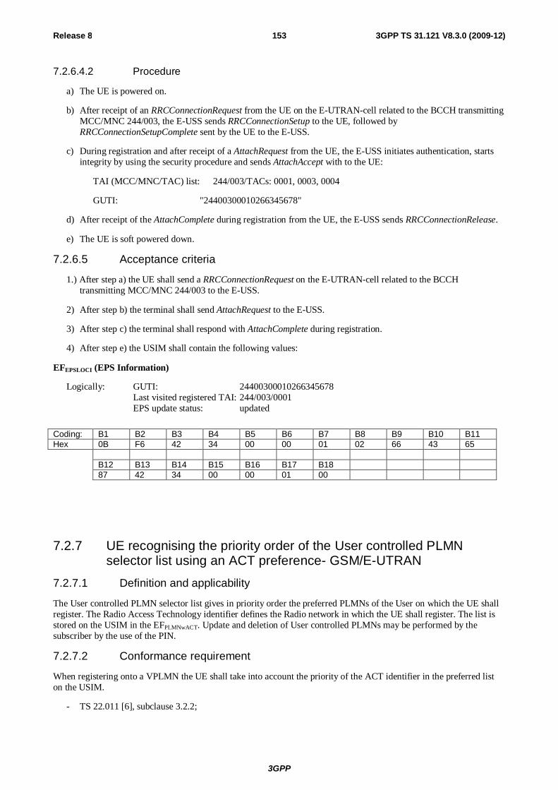
3GPP
Release 8 153 3GPP TS 31.121 V8.3.0 (2009-12)
7.2.6.4.2 Procedure
a) The UE is powered on.
b) After receipt of an RRCConnectionRequest from the UE on the E-UTRAN-cell related to the BCCH transmitting MCC/MNC 244/003, the E-USS sends RRCConnectionSetup to the UE, followed by RRCConnectionSetupComplete sent by the UE to the E-USS.
c) During registration and after receipt of a AttachRequest from the UE, the E-USS initiates authentication, starts integrity by using the security procedure and sends AttachAccept with to the UE:
TAI (MCC/MNC/TAC) list: 244/003/TACs: 0001, 0003, 0004
GUTI: "24400300010266345678"
d) After receipt of the AttachComplete during registration from the UE, the E-USS sends RRCConnectionRelease.
e) The UE is soft powered down.
7.2.6.5 Acceptance criteria
1.) After step a) the UE shall send a RRCConnectionRequest on the E-UTRAN-cell related to the BCCH transmitting MCC/MNC 244/003 to the E-USS.
2) After step b) the terminal shall send AttachRequest to the E-USS.
3) After step c) the terminal shall respond with AttachComplete during registration.
4) After step e) the USIM shall contain the following values:
EFEPSLOCI (EPS Information)
Logically: GUTI: 24400300010266345678 Last visited registered TAI: 244/003/0001 EPS update status: updated
Coding: B1 B2 B3 B4 B5 B6 B7 B8 B9 B10 B11 Hex 0B F6 42 34 00 00 01 02 66 43 65 B12 B13 B14 B15 B16 B17 B18 87 42 34 00 00 01 00
7.2.7 UE recognising the priority order of the User controlled PLMN selector list using an ACT preference- GSM/E-UTRAN
7.2.7.1 Definition and applicability
The User controlled PLMN selector list gives in priority order the preferred PLMNs of the User on which the UE shall register. The Radio Access Technology identifier defines the Radio network in which the UE shall register. The list is stored on the USIM in the EFPLMNwACT. Update and deletion of User controlled PLMNs may be performed by the subscriber by the use of the PIN.
7.2.7.2 Conformance requirement
When registering onto a VPLMN the UE shall take into account the priority of the ACT identifier in the preferred list on the USIM.
- TS 22.011 [6], subclause 3.2.2;
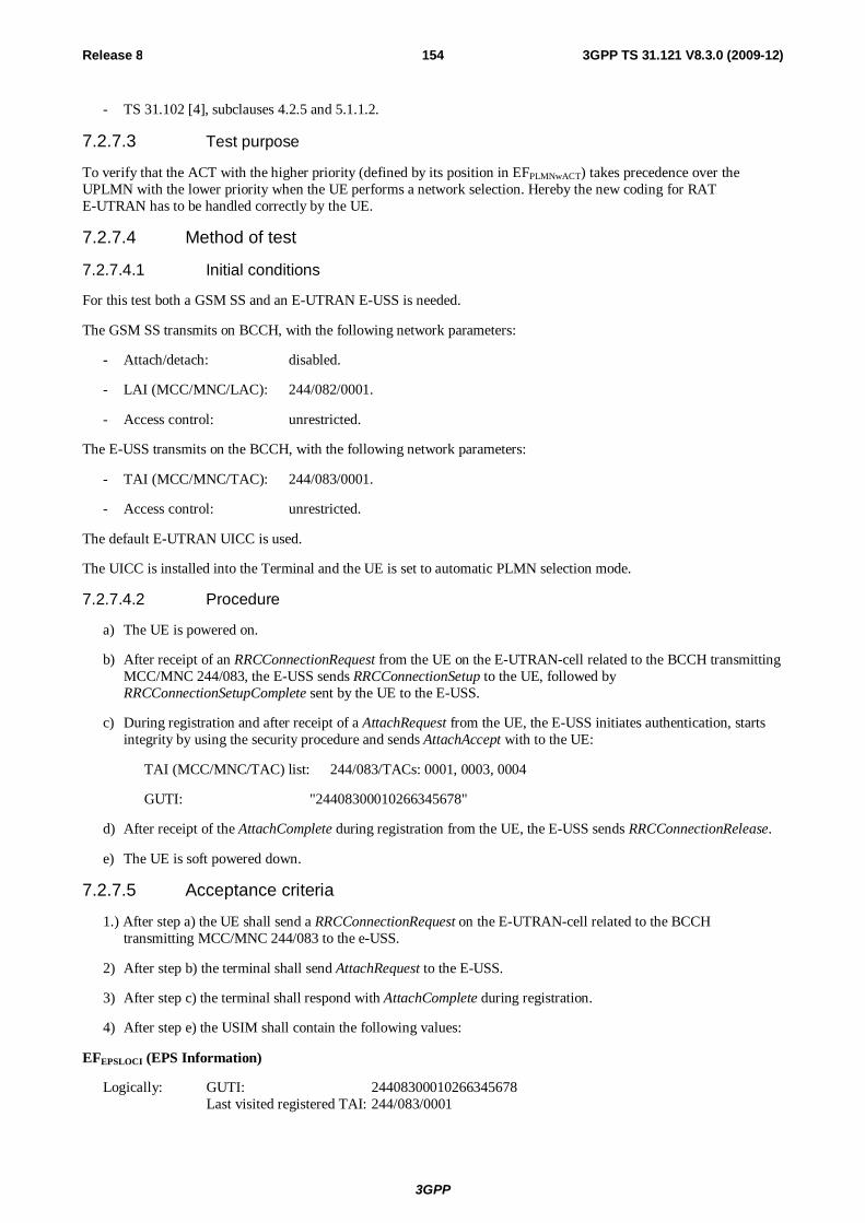
3GPP
Release 8 154 3GPP TS 31.121 V8.3.0 (2009-12)
- TS 31.102 [4], subclauses 4.2.5 and 5.1.1.2.
7.2.7.3 Test purpose
To verify that the ACT with the higher priority (defined by its position in EFPLMNwACT) takes precedence over the UPLMN with the lower priority when the UE performs a network selection. Hereby the new coding for RAT E-UTRAN has to be handled correctly by the UE.
7.2.7.4 Method of test
7.2.7.4.1 Initial conditions
For this test both a GSM SS and an E-UTRAN E-USS is needed.
The GSM SS transmits on BCCH, with the following network parameters:
- Attach/detach: disabled.
- LAI (MCC/MNC/LAC): 244/082/0001.
- Access control: unrestricted.
The E-USS transmits on the BCCH, with the following network parameters:
- TAI (MCC/MNC/TAC): 244/083/0001.
- Access control: unrestricted.
The default E-UTRAN UICC is used.
The UICC is installed into the Terminal and the UE is set to automatic PLMN selection mode.
7.2.7.4.2 Procedure
a) The UE is powered on.
b) After receipt of an RRCConnectionRequest from the UE on the E-UTRAN-cell related to the BCCH transmitting MCC/MNC 244/083, the E-USS sends RRCConnectionSetup to the UE, followed by RRCConnectionSetupComplete sent by the UE to the E-USS.
c) During registration and after receipt of a AttachRequest from the UE, the E-USS initiates authentication, starts integrity by using the security procedure and sends AttachAccept with to the UE:
TAI (MCC/MNC/TAC) list: 244/083/TACs: 0001, 0003, 0004
GUTI: "24408300010266345678"
d) After receipt of the AttachComplete during registration from the UE, the E-USS sends RRCConnectionRelease.
e) The UE is soft powered down.
7.2.7.5 Acceptance criteria
1.) After step a) the UE shall send a RRCConnectionRequest on the E-UTRAN-cell related to the BCCH transmitting MCC/MNC 244/083 to the e-USS.
2) After step b) the terminal shall send AttachRequest to the E-USS.
3) After step c) the terminal shall respond with AttachComplete during registration.
4) After step e) the USIM shall contain the following values:
EFEPSLOCI (EPS Information)
Logically: GUTI: 24408300010266345678 Last visited registered TAI: 244/083/0001
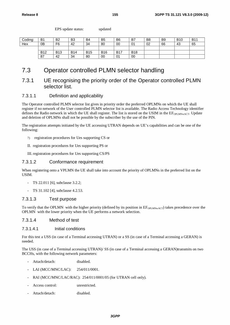
3GPP
Release 8 155 3GPP TS 31.121 V8.3.0 (2009-12)
EPS update status: updated
Coding: B1 B2 B3 B4 B5 B6 B7 B8 B9 B10 B11 Hex 0B F6 42 34 80 00 01 02 66 43 65 B12 B13 B14 B15 B16 B17 B18 87 42 34 80 00 01 00
7.3 Operator controlled PLMN selector handling 7.3.1 UE recognising the priority order of the Operator controlled PLMN
selector list.
7.3.1.1 Definition and applicability
The Operator controlled PLMN selector list gives in priority order the preferred OPLMNs on which the UE shall register if no network of the User controlled PLMN selector list is available. The Radio Access Technology identifier defines the Radio network in which the UE shall register. The list is stored on the USIM in the EFOPLMNwACT. Update and deletion of OPLMNs shall not be possible by the subscriber by the use of the PIN.
The registration attempts initiated by the UE accessing UTRAN depends on UE’s capabilities and can be one of the following:
7) registration procedures for Ues supporting CS or
II. registration procedures for Ues supporting PS or
III. registration procedures for Ues supporting CS/PS
7.3.1.2 Conformance requirement
When registering onto a VPLMN the UE shall take into account the priority of OPLMNs in the preferred list on the USIM.
- TS 22.011 [6], subclause 3.2.2;
- TS 31.102 [4], subclause 4.2.53.
7.3.1.3 Test purpose
To verify that the OPLMN with the higher priority (defined by its position in EFOPLMNwACT) takes precedence over the OPLMN with the lower priority when the UE performs a network selection.
7.3.1.4 Method of test
7.3.1.4.1 Initial conditions
For this test a USS (in case of a Terminal accessing UTRAN) or a SS (in case of a Terminal accessing a GERAN) is needed.
The USS (in case of a Terminal accessing UTRAN)/ SS (in case of a Terminal accessing a GERAN)transmits on two BCCHs, with the following network parameters:
- Attach/detach: disabled.
- LAI (MCC/MNC/LAC): 254/011/0001.
- RAI (MCC/MNC/LAC/RAC): 254/011/0001/05 (for UTRAN cell only).
- Access control: unrestricted.
- Attach/detach: disabled.
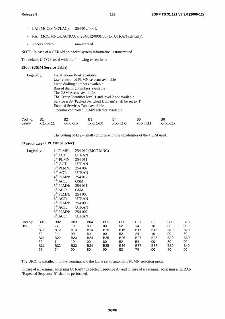
3GPP
Release 8 156 3GPP TS 31.121 V8.3.0 (2009-12)
- LAI (MCC/MNC/LAC): 254/012/0001.
- RAI (MCC/MNC/LAC/RAC): 254/012/0001/05 (for UTRAN cell only).
- Access control: unrestricted.
NOTE: In case of a GERAN no packet system information is transmitted.
The default UICC is used with the following exceptions:
EFUST (USIM Service Table)
Logically: Local Phone Book available User controlled PLMN selector available Fixed dialling numbers available Barred dialling numbers available The GSM Access available The Group Identifier level 1 and level 2 not available Service n 33 (Packed Switched Domain) shall be set to '1' Enabled Services Table available Operator controlled PLMN selector available
Coding: B1 B2 B3 B4 B5 B6 binary xx1x xx11 xxxx xxxx xxxx 1x00 xxxx x1xx xxxx xx11 xxxx xx1x
The coding of EFUST shall conform with the capabilities of the USIM used.
EFOPLMNwACT (OPLMN Selector)
Logically: 1st PLMN: 254 012 (MCC MNC) 1st ACT UTRAN 2nd PLMN: 254 011 2nd ACT UTRAN 3rd PLMN: 254 002 3rd ACT: UTRAN 4th PLMN: 254 012 4th ACT: GSM 5th PLMN: 254 011 5th ACT: GSM 6th PLMN: 254 005 6th ACT: UTRAN 7th PLMN: 254 006 7th ACT: UTRAN 8th PLMN: 254 007 8th ACT: UTRAN
Coding: B01 B02 B03 B04 B05 B06 B07 B08 B09 B10 Hex 52 24 10 80 00 52 14 10 80 00 B11 B12 B13 B14 B15 B16 B17 B18 B19 B20 52 24 00 80 00 52 24 10 00 80 B21 B22 B23 B24 B25 B26 B27 B28 B29 B30 52 14 10 00 80 52 54 00 80 00 B31 B32 B33 B34 B35 B36 B37 B38 B39 B40 52 64 00 80 00 52 74 00 80 00
The UICC is installed into the Terminal and the UE is set to automatic PLMN selection mode.
In case of a Terminal accessing UTRAN "Expected Sequence A" and in case of a Terminal accessing a GERAN "Expected Sequence B" shall be performed.
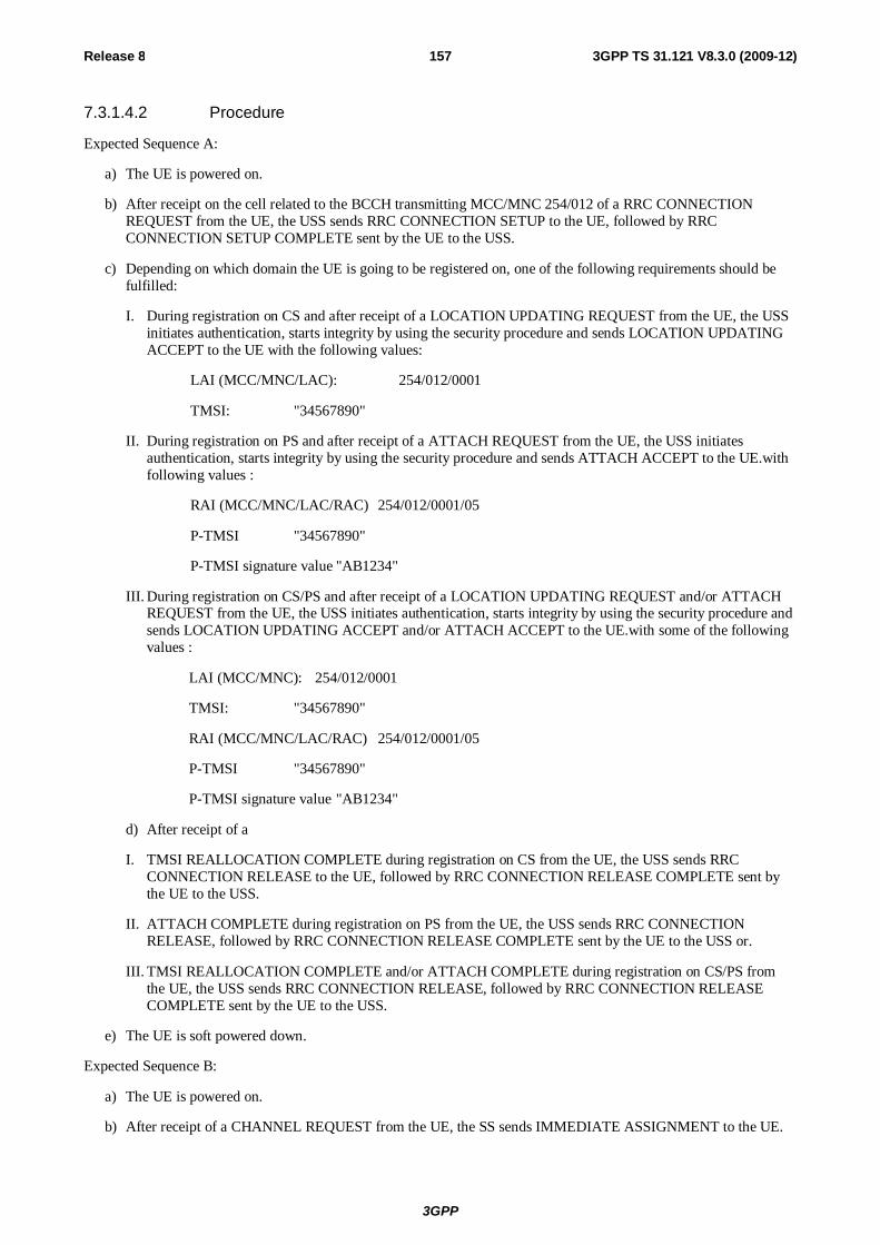
3GPP
Release 8 157 3GPP TS 31.121 V8.3.0 (2009-12)
7.3.1.4.2 Procedure
Expected Sequence A:
a) The UE is powered on.
b) After receipt on the cell related to the BCCH transmitting MCC/MNC 254/012 of a RRC CONNECTION REQUEST from the UE, the USS sends RRC CONNECTION SETUP to the UE, followed by RRC CONNECTION SETUP COMPLETE sent by the UE to the USS.
c) Depending on which domain the UE is going to be registered on, one of the following requirements should be fulfilled:
I. During registration on CS and after receipt of a LOCATION UPDATING REQUEST from the UE, the USS initiates authentication, starts integrity by using the security procedure and sends LOCATION UPDATING ACCEPT to the UE with the following values:
LAI (MCC/MNC/LAC): 254/012/0001
TMSI: "34567890"
II. During registration on PS and after receipt of a ATTACH REQUEST from the UE, the USS initiates authentication, starts integrity by using the security procedure and sends ATTACH ACCEPT to the UE.with following values :
RAI (MCC/MNC/LAC/RAC) 254/012/0001/05
P-TMSI "34567890"
P-TMSI signature value "AB1234"
III. During registration on CS/PS and after receipt of a LOCATION UPDATING REQUEST and/or ATTACH REQUEST from the UE, the USS initiates authentication, starts integrity by using the security procedure and sends LOCATION UPDATING ACCEPT and/or ATTACH ACCEPT to the UE.with some of the following values :
LAI (MCC/MNC): 254/012/0001
TMSI: "34567890"
RAI (MCC/MNC/LAC/RAC) 254/012/0001/05
P-TMSI "34567890"
P-TMSI signature value "AB1234"
d) After receipt of a
I. TMSI REALLOCATION COMPLETE during registration on CS from the UE, the USS sends RRC CONNECTION RELEASE to the UE, followed by RRC CONNECTION RELEASE COMPLETE sent by the UE to the USS.
II. ATTACH COMPLETE during registration on PS from the UE, the USS sends RRC CONNECTION RELEASE, followed by RRC CONNECTION RELEASE COMPLETE sent by the UE to the USS or.
III. TMSI REALLOCATION COMPLETE and/or ATTACH COMPLETE during registration on CS/PS from the UE, the USS sends RRC CONNECTION RELEASE, followed by RRC CONNECTION RELEASE COMPLETE sent by the UE to the USS.
e) The UE is soft powered down.
Expected Sequence B:
a) The UE is powered on.
b) After receipt of a CHANNEL REQUEST from the UE, the SS sends IMMEDIATE ASSIGNMENT to the UE.
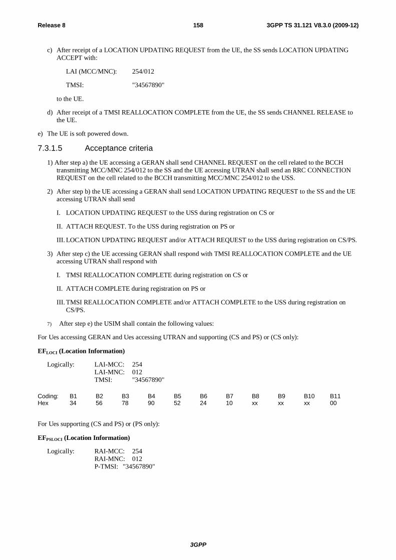
3GPP
Release 8 158 3GPP TS 31.121 V8.3.0 (2009-12)
c) After receipt of a LOCATION UPDATING REQUEST from the UE, the SS sends LOCATION UPDATING ACCEPT with:
LAI (MCC/MNC): 254/012
TMSI: "34567890"
to the UE.
d) After receipt of a TMSI REALLOCATION COMPLETE from the UE, the SS sends CHANNEL RELEASE to the UE.
e) The UE is soft powered down.
7.3.1.5 Acceptance criteria
1) After step a) the UE accessing a GERAN shall send CHANNEL REQUEST on the cell related to the BCCH transmitting MCC/MNC 254/012 to the SS and the UE accessing UTRAN shall send an RRC CONNECTION REQUEST on the cell related to the BCCH transmitting MCC/MNC 254/012 to the USS.
2) After step b) the UE accessing a GERAN shall send LOCATION UPDATING REQUEST to the SS and the UE accessing UTRAN shall send
I. LOCATION UPDATING REQUEST to the USS during registration on CS or
II. ATTACH REQUEST. To the USS during registration on PS or
III. LOCATION UPDATING REQUEST and/or ATTACH REQUEST to the USS during registration on CS/PS.
3) After step c) the UE accessing GERAN shall respond with TMSI REALLOCATION COMPLETE and the UE accessing UTRAN shall respond with
I. TMSI REALLOCATION COMPLETE during registration on CS or
II. ATTACH COMPLETE during registration on PS or
III. TMSI REALLOCATION COMPLETE and/or ATTACH COMPLETE to the USS during registration on CS/PS.
7) After step e) the USIM shall contain the following values:
For Ues accessing GERAN and Ues accessing UTRAN and supporting (CS and PS) or (CS only):
EFLOCI (Location Information)
Logically: LAI-MCC: 254 LAI-MNC: 012 TMSI: "34567890"
Coding: B1 B2 B3 B4 B5 B6 B7 B8 B9 B10 B11 Hex 34 56 78 90 52 24 10 xx xx xx 00
For Ues supporting (CS and PS) or (PS only):
EFPSLOCI (Location Information)
Logically: RAI-MCC: 254 RAI-MNC: 012 P-TMSI: "34567890"
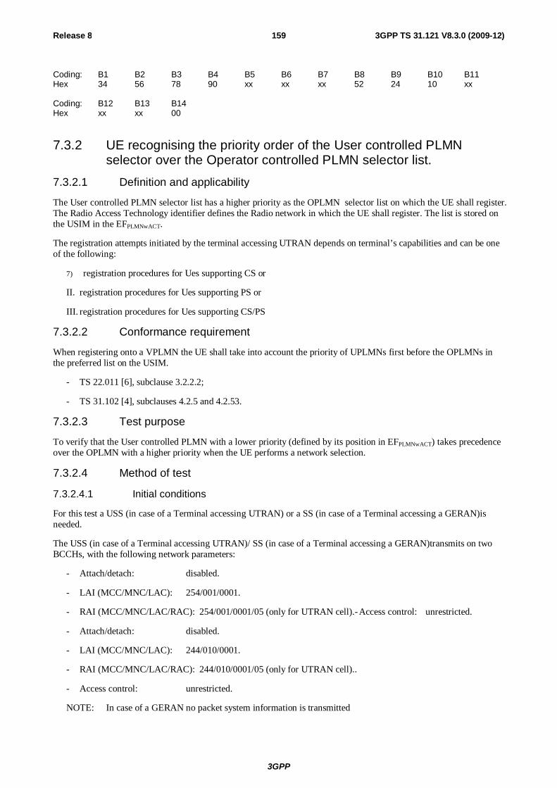
3GPP
Release 8 159 3GPP TS 31.121 V8.3.0 (2009-12)
Coding: B1 B2 B3 B4 B5 B6 B7 B8 B9 B10 B11 Hex 34 56 78 90 xx xx xx 52 24 10 xx Coding: B12 B13 B14 Hex xx xx 00
7.3.2 UE recognising the priority order of the User controlled PLMN selector over the Operator controlled PLMN selector list.
7.3.2.1 Definition and applicability
The User controlled PLMN selector list has a higher priority as the OPLMN selector list on which the UE shall register. The Radio Access Technology identifier defines the Radio network in which the UE shall register. The list is stored on the USIM in the EFPLMNwACT.
The registration attempts initiated by the terminal accessing UTRAN depends on terminal’s capabilities and can be one of the following:
7) registration procedures for Ues supporting CS or
II. registration procedures for Ues supporting PS or
III. registration procedures for Ues supporting CS/PS
7.3.2.2 Conformance requirement
When registering onto a VPLMN the UE shall take into account the priority of UPLMNs first before the OPLMNs in the preferred list on the USIM.
- TS 22.011 [6], subclause 3.2.2.2;
- TS 31.102 [4], subclauses 4.2.5 and 4.2.53.
7.3.2.3 Test purpose
To verify that the User controlled PLMN with a lower priority (defined by its position in EFPLMNwACT) takes precedence over the OPLMN with a higher priority when the UE performs a network selection.
7.3.2.4 Method of test
7.3.2.4.1 Initial conditions
For this test a USS (in case of a Terminal accessing UTRAN) or a SS (in case of a Terminal accessing a GERAN)is needed.
The USS (in case of a Terminal accessing UTRAN)/ SS (in case of a Terminal accessing a GERAN)transmits on two BCCHs, with the following network parameters:
- Attach/detach: disabled.
- LAI (MCC/MNC/LAC): 254/001/0001.
- RAI (MCC/MNC/LAC/RAC): 254/001/0001/05 (only for UTRAN cell).- Access control: unrestricted.
- Attach/detach: disabled.
- LAI (MCC/MNC/LAC): 244/010/0001.
- RAI (MCC/MNC/LAC/RAC): 244/010/0001/05 (only for UTRAN cell)..
- Access control: unrestricted.
NOTE: In case of a GERAN no packet system information is transmitted
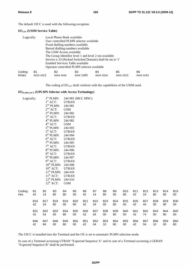
3GPP
Release 8 160 3GPP TS 31.121 V8.3.0 (2009-12)
The default UICC is used with the following exception:
EFUST (USIM Service Table)
Logically: Local Phone Book available User controlled PLMN selector available Fixed dialling numbers available Barred dialling numbers available The GSM Access available The Group Identifier level 1 and level 2 not available Service n 33 (Packed Switched Domain) shall be set to '1' Enabled Services Table available
Operator controlled PLMN selector available
Coding: B1 B2 B3 B4 B5 B6 binary xx1x xx11 xxxx xxxx xxxx 1x00 xxxx x1xx xxxx xx11 xxxx xx1x
The coding of EFUST shall conform with the capabilities of the USIM used.
EFPLMNwACT (UPLMN Selector with Access Technology)
Logically: 1st PLMN: 244 081 (MCC MNC) 1st ACT: UTRAN 2nd PLMN: 244 081 2nd ACT: GSM 3rd PLMN: 244 082 3rd ACT: UTRAN 4th PLMN: 244 082 4th ACT: GSM 5th PLMN: 244 003 5th ACT: UTRAN 6th PLMN: 244 004 6th ACT: UTRAN 7th PLMN: 244 005 7th ACT: UTRAN 8th PLMN: 244 006 8th ACT: UTRAN 9th PLMN: 244 007 9th ACT: UTRAN 10th PLMN: 244 008 10th ACT: UTRAN 11th PLMN: 244 010 11th ACT: UTRAN 12th PLMN: 244 010 12th ACT: GSM
Coding: B1 B2 B3 B4 B5 B6 B7 B8 B9 B10 B11 B12 B13 B14 B15 Hex 42 14 80 80 00 42 14 80 00 80 42 24 80 80 00 B16 B17 B18 B19 B20 B21 B22 B23 B24 B25 B26 B27 B28 B29 B30 42 24 80 00 80 42 24 00 80 00 42 44 00 80 00 B31 B32 B33 B34 B35 B36 B37 B38 B39 B40 B41 B42 B43 B44 B45 42 54 00 80 00 42 64 00 80 00 42 74 00 80 00 B46 B47 B48 B49 B50 B51 B52 B53 B54 B55 B56 B57 B58 B59 B60 42 84 00 80 00 42 04 10 80 00 42 04 10 00 80
The UICC is installed into the Terminal and the UE is set to automatic PLMN selection mode.
In case of a Terminal accessing UTRAN "Expected Sequence A" and in case of a Terminal accessing a GERAN "Expected Sequence B" shall be performed.
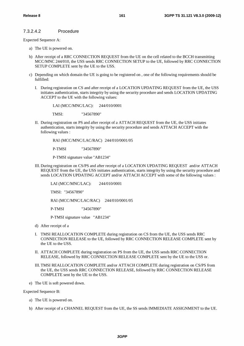
3GPP
Release 8 161 3GPP TS 31.121 V8.3.0 (2009-12)
7.3.2.4.2 Procedure
Expected Sequence A:
a) The UE is powered on.
b) After receipt of a RRC CONNECTION REQUEST from the UE on the cell related to the BCCH transmitting MCC/MNC 244/010, the USS sends RRC CONNECTION SETUP to the UE, followed by RRC CONNECTION SETUP COMPLETE sent by the UE to the USS.
c) Depending on which domain the UE is going to be registered on , one of the following requirements should be fulfilled:
I. During registration on CS and after receipt of a LOCATION UPDATING REQUEST from the UE, the USS initiates authentication, starts integrity by using the security procedure and sends LOCATION UPDATING ACCEPT to the UE with the following values:
LAI (MCC/MNC/LAC): 244/010/0001
TMSI: "34567890"
II. During registration on PS and after receipt of a ATTACH REQUEST from the UE, the USS initiates authentication, starts integrity by using the security procedure and sends ATTACH ACCEPT with the following values :
RAI (MCC/MNC/LAC/RAC) 244/010/0001/05
P-TMSI "34567890"
P-TMSI signature value "AB1234"
III. During registration on CS/PS and after receipt of a LOCATION UPDATING REQUEST and/or ATTACH REQUEST from the UE, the USS initiates authentication, starts integrity by using the security procedure and sends LOCATION UPDATING ACCEPT and/or ATTACH ACCEPT with some of the following values :
LAI (MCC/MNC/LAC): 244/010/0001
TMSI: "34567890"
RAI (MCC/MNC/LAC/RAC) 244/010/0001/05
P-TMSI "34567890"
P-TMSI signature value "AB1234"
d) After receipt of a
I. TMSI REALLOCATION COMPLETE during registration on CS from the UE, the USS sends RRC CONNECTION RELEASE to the UE, followed by RRC CONNECTION RELEASE COMPLETE sent by the UE to the USS.
II. ATTACH COMPLETE during registration on PS from the UE, the USS sends RRC CONNECTION RELEASE, followed by RRC CONNECTION RELEASE COMPLETE sent by the UE to the USS or.
III. TMSI REALLOCATION COMPLETE and/or ATTACH COMPLETE during registration on CS/PS from the UE, the USS sends RRC CONNECTION RELEASE, followed by RRC CONNECTION RELEASE COMPLETE sent by the UE to the USS.
e) The UE is soft powered down.
Expected Sequence B:
a) The UE is powered on.
b) After receipt of a CHANNEL REQUEST from the UE, the SS sends IMMEDIATE ASSIGNMENT to the UE.
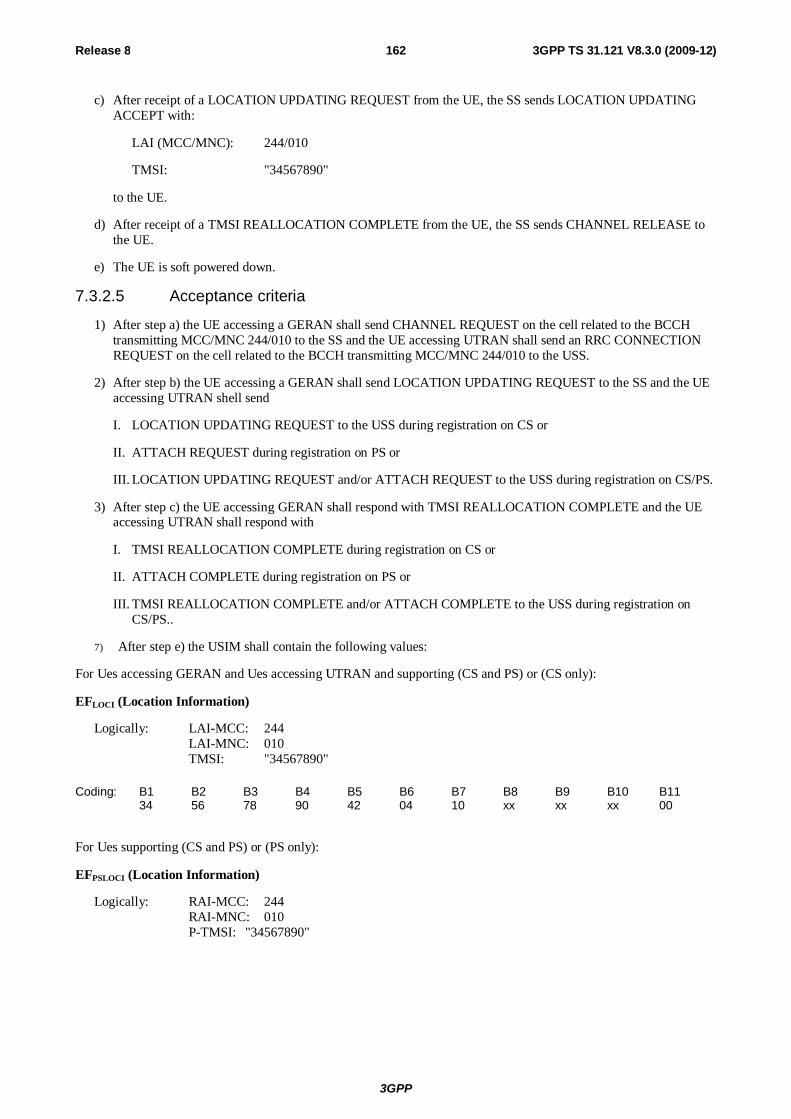
3GPP
Release 8 162 3GPP TS 31.121 V8.3.0 (2009-12)
c) After receipt of a LOCATION UPDATING REQUEST from the UE, the SS sends LOCATION UPDATING ACCEPT with:
LAI (MCC/MNC): 244/010
TMSI: "34567890"
to the UE.
d) After receipt of a TMSI REALLOCATION COMPLETE from the UE, the SS sends CHANNEL RELEASE to the UE.
e) The UE is soft powered down.
7.3.2.5 Acceptance criteria
1) After step a) the UE accessing a GERAN shall send CHANNEL REQUEST on the cell related to the BCCH transmitting MCC/MNC 244/010 to the SS and the UE accessing UTRAN shall send an RRC CONNECTION REQUEST on the cell related to the BCCH transmitting MCC/MNC 244/010 to the USS.
2) After step b) the UE accessing a GERAN shall send LOCATION UPDATING REQUEST to the SS and the UE accessing UTRAN shell send
I. LOCATION UPDATING REQUEST to the USS during registration on CS or
II. ATTACH REQUEST during registration on PS or
III. LOCATION UPDATING REQUEST and/or ATTACH REQUEST to the USS during registration on CS/PS.
3) After step c) the UE accessing GERAN shall respond with TMSI REALLOCATION COMPLETE and the UE accessing UTRAN shall respond with
I. TMSI REALLOCATION COMPLETE during registration on CS or
II. ATTACH COMPLETE during registration on PS or
III. TMSI REALLOCATION COMPLETE and/or ATTACH COMPLETE to the USS during registration on CS/PS..
7) After step e) the USIM shall contain the following values:
For Ues accessing GERAN and Ues accessing UTRAN and supporting (CS and PS) or (CS only):
EFLOCI (Location Information)
Logically: LAI-MCC: 244 LAI-MNC: 010 TMSI: "34567890"
Coding: B1 B2 B3 B4 B5 B6 B7 B8 B9 B10 B11 34 56 78 90 42 04 10 xx xx xx 00
For Ues supporting (CS and PS) or (PS only):
EFPSLOCI (Location Information)
Logically: RAI-MCC: 244 RAI-MNC: 010 P-TMSI: "34567890"
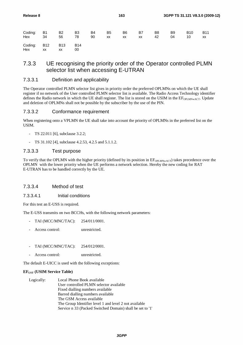
3GPP
Release 8 163 3GPP TS 31.121 V8.3.0 (2009-12)
Coding: B1 B2 B3 B4 B5 B6 B7 B8 B9 B10 B11 Hex 34 56 78 90 xx xx xx 42 04 10 xx Coding: B12 B13 B14 Hex xx xx 00
7.3.3 UE recognising the priority order of the Operator controlled PLMN selector list when accessing E-UTRAN
7.3.3.1 Definition and applicability
The Operator controlled PLMN selector list gives in priority order the preferred OPLMNs on which the UE shall register if no network of the User controlled PLMN selector list is available. The Radio Access Technology identifier defines the Radio network in which the UE shall register. The list is stored on the USIM in the EFOPLMNwACT. Update and deletion of OPLMNs shall not be possible by the subscriber by the use of the PIN.
7.3.3.2 Conformance requirement
When registering onto a VPLMN the UE shall take into account the priority of OPLMNs in the preferred list on the USIM.
- TS 22.011 [6], subclause 3.2.2;
- TS 31.102 [4], subclause 4.2.53, 4.2.5 and 5.1.1.2.
7.3.3.3 Test purpose
To verify that the OPLMN with the higher priority (defined by its position in EFOPLMNwACT) takes precedence over the OPLMN with the lower priority when the UE performs a network selection. Hereby the new coding for RAT E-UTRAN has to be handled correctly by the UE.
7.3.3.4 Method of test
7.3.3.4.1 Initial conditions
For this test an E-USS is required.
The E-USS transmits on two BCCHs, with the following network parameters:
- TAI (MCC/MNC/TAC): 254/011/0001.
- Access control: unrestricted.
- TAI (MCC/MNC/TAC): 254/012/0001.
- Access control: unrestricted.
The default E-UICC is used with the following exceptions:
EFUST (USIM Service Table)
Logically: Local Phone Book available User controlled PLMN selector available Fixed dialling numbers available Barred dialling numbers available The GSM Access available The Group Identifier level 1 and level 2 not available Service n 33 (Packed Switched Domain) shall be set to '1'
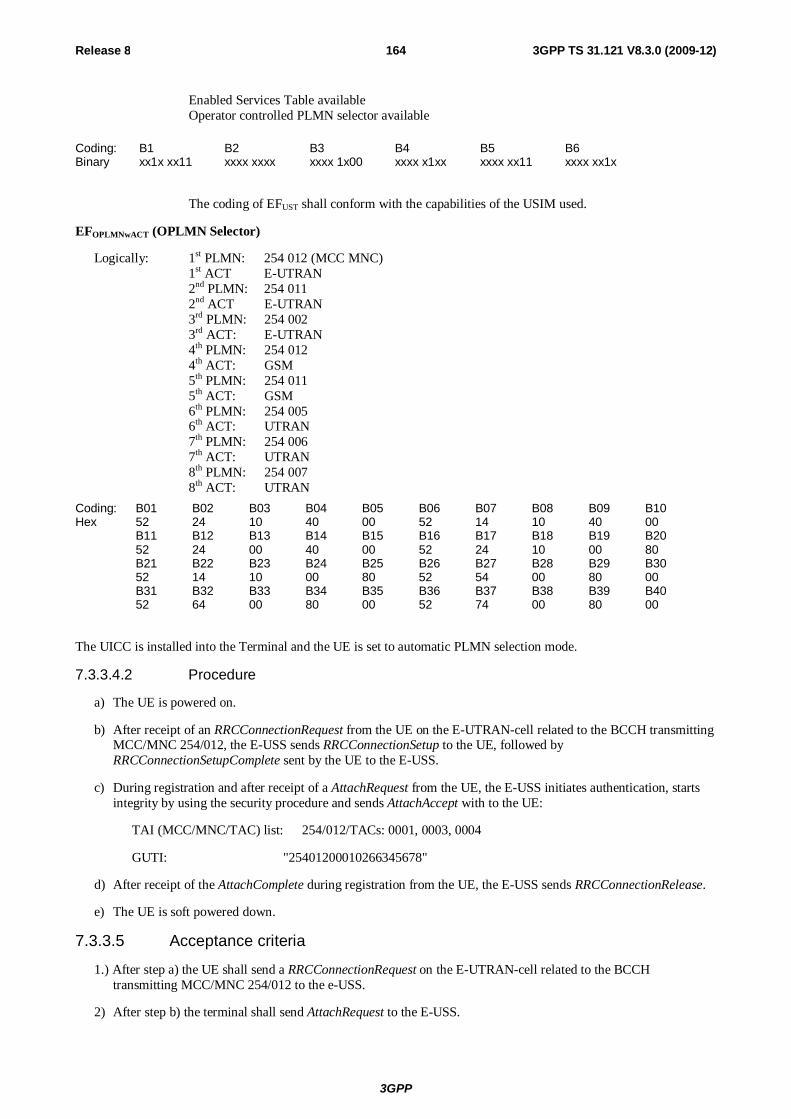
3GPP
Release 8 164 3GPP TS 31.121 V8.3.0 (2009-12)
Enabled Services Table available Operator controlled PLMN selector available
Coding: B1 B2 B3 B4 B5 B6 Binary xx1x xx11 xxxx xxxx xxxx 1x00 xxxx x1xx xxxx xx11 xxxx xx1x
The coding of EFUST shall conform with the capabilities of the USIM used.
EFOPLMNwACT (OPLMN Selector)
Logically: 1st PLMN: 254 012 (MCC MNC) 1st ACT E-UTRAN 2nd PLMN: 254 011 2nd ACT E-UTRAN 3rd PLMN: 254 002 3rd ACT: E-UTRAN 4th PLMN: 254 012 4th ACT: GSM 5th PLMN: 254 011 5th ACT: GSM 6th PLMN: 254 005 6th ACT: UTRAN 7th PLMN: 254 006 7th ACT: UTRAN 8th PLMN: 254 007 8th ACT: UTRAN
Coding: B01 B02 B03 B04 B05 B06 B07 B08 B09 B10 Hex 52 24 10 40 00 52 14 10 40 00 B11 B12 B13 B14 B15 B16 B17 B18 B19 B20 52 24 00 40 00 52 24 10 00 80 B21 B22 B23 B24 B25 B26 B27 B28 B29 B30 52 14 10 00 80 52 54 00 80 00 B31 B32 B33 B34 B35 B36 B37 B38 B39 B40 52 64 00 80 00 52 74 00 80 00
The UICC is installed into the Terminal and the UE is set to automatic PLMN selection mode.
7.3.3.4.2 Procedure
a) The UE is powered on.
b) After receipt of an RRCConnectionRequest from the UE on the E-UTRAN-cell related to the BCCH transmitting MCC/MNC 254/012, the E-USS sends RRCConnectionSetup to the UE, followed by RRCConnectionSetupComplete sent by the UE to the E-USS.
c) During registration and after receipt of a AttachRequest from the UE, the E-USS initiates authentication, starts integrity by using the security procedure and sends AttachAccept with to the UE:
TAI (MCC/MNC/TAC) list: 254/012/TACs: 0001, 0003, 0004
GUTI: "25401200010266345678"
d) After receipt of the AttachComplete during registration from the UE, the E-USS sends RRCConnectionRelease.
e) The UE is soft powered down.
7.3.3.5 Acceptance criteria
1.) After step a) the UE shall send a RRCConnectionRequest on the E-UTRAN-cell related to the BCCH transmitting MCC/MNC 254/012 to the e-USS.
2) After step b) the terminal shall send AttachRequest to the E-USS.

3GPP
Release 8 165 3GPP TS 31.121 V8.3.0 (2009-12)
3) After step c) the terminal shall respond with AttachComplete during registration.
4) After step e) the USIM shall contain the following values:
EFEPSLOCI (EPS Information)
Logically: GUTI: 25401200010266345678 Last visited registered TAI: 254/012/0001 EPS update status: updated
Coding: B1 B2 B3 B4 B5 B6 B7 B8 B9 B10 B11 Hex 0B F6 52 24 10 00 01 02 66 43 65 B12 B13 B14 B15 B16 B17 B18 87 52 24 10 00 01 00
7.3.4 UE recognising the priority order of the User controlled PLMN selector over the Operator controlled PLMN selector list – E-UTRAN
7.3.4.1 Definition and applicability
The User controlled PLMN selector list has a higher priority as the OPLMN selector list on which the UE shall register. The Radio Access Technology identifier defines the Radio network in which the UE shall register. The list is stored on the USIM in the EFPLMNwACT.
7.3.4.2 Conformance requirement
When registering onto a VPLMN the UE shall take into account the priority of UPLMNs first before the OPLMNs in the preferred list on the USIM.
- TS 22.011 [6], subclause 3.2.2.2;
- TS 31.102 [4], subclauses 4.2.5, 4.2.53 and 5.1.1.2.
7.3.4.3 Test purpose
To verify that the User controlled PLMN with a lower priority (defined by its position in EFPLMNwACT) takes precedence over the OPLMN with a higher priority when the UE performs a network selection. Hereby the new coding for RAT E-UTRAN has to be handled correctly by the UE.
7.3.4.4 Method of test
7.3.4.4.1 Initial conditions
For this test an E-USS is required.
The E-USS transmits on two BCCHs, with the following network parameters:
- TAI (MCC/MNC/TAC): 254/001/0001.
-- Access control: unrestricted.
- TAI (MCC/MNC/TAC): 244/010/0001.
- Access control: unrestricted.
The default E-UICC is used with the following exception:
EFUST (USIM Service Table)
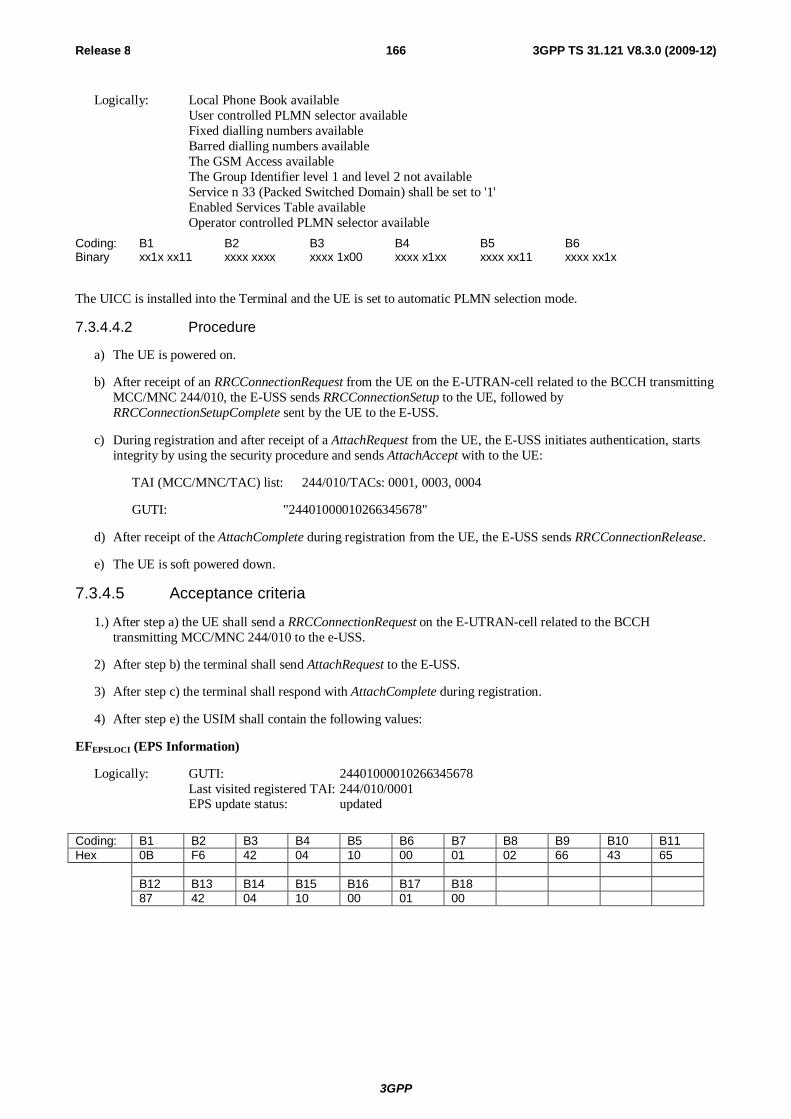
3GPP
Release 8 166 3GPP TS 31.121 V8.3.0 (2009-12)
Logically: Local Phone Book available User controlled PLMN selector available Fixed dialling numbers available Barred dialling numbers available The GSM Access available The Group Identifier level 1 and level 2 not available Service n 33 (Packed Switched Domain) shall be set to '1' Enabled Services Table available
Operator controlled PLMN selector available
Coding: B1 B2 B3 B4 B5 B6 Binary xx1x xx11 xxxx xxxx xxxx 1x00 xxxx x1xx xxxx xx11 xxxx xx1x
The UICC is installed into the Terminal and the UE is set to automatic PLMN selection mode.
7.3.4.4.2 Procedure
a) The UE is powered on.
b) After receipt of an RRCConnectionRequest from the UE on the E-UTRAN-cell related to the BCCH transmitting MCC/MNC 244/010, the E-USS sends RRCConnectionSetup to the UE, followed by RRCConnectionSetupComplete sent by the UE to the E-USS.
c) During registration and after receipt of a AttachRequest from the UE, the E-USS initiates authentication, starts integrity by using the security procedure and sends AttachAccept with to the UE:
TAI (MCC/MNC/TAC) list: 244/010/TACs: 0001, 0003, 0004
GUTI: "24401000010266345678"
d) After receipt of the AttachComplete during registration from the UE, the E-USS sends RRCConnectionRelease.
e) The UE is soft powered down.
7.3.4.5 Acceptance criteria
1.) After step a) the UE shall send a RRCConnectionRequest on the E-UTRAN-cell related to the BCCH transmitting MCC/MNC 244/010 to the e-USS.
2) After step b) the terminal shall send AttachRequest to the E-USS.
3) After step c) the terminal shall respond with AttachComplete during registration.
4) After step e) the USIM shall contain the following values:
EFEPSLOCI (EPS Information)
Logically: GUTI: 24401000010266345678 Last visited registered TAI: 244/010/0001 EPS update status: updated
Coding: B1 B2 B3 B4 B5 B6 B7 B8 B9 B10 B11 Hex 0B F6 42 04 10 00 01 02 66 43 65 B12 B13 B14 B15 B16 B17 B18 87 42 04 10 00 01 00
3GPP
Release 8 167 3GPP TS 31.121 V8.3.0 (2009-12)
7.4 Higher priority PLMN search handling 7.4.1 UE recognising the search period of the Higher priority PLMN 7.4.1.1 Definition and applicability
The Higher priority PLMN list gives in priority order the Higher priority PLMN on which the UE shall register first. The Higher priority PLMN search period gives the time interval in which the UE shall search for a possible Higher priority PLMN registration.
The registration attempts initiated by the terminal accessing UTRAN depends on terminal’s capabilities and can be one of the following:
7) registration procedures for Ues supporting CS or
II. registration procedures for Ues supporting PS or
III. registration procedures for Ues supporting CS/PS
7.4.1.2 Conformance requirement
After registered onto a VPLMN the UE shall take into account the Higher priority PLMN search period timer and the priority order of the Higher priority PLMNs in the preferred list on the USIM.
- TS 22.011 [6], subclauses 3.2.2 and 3.2.2.5.
- TS 24.008 [16], subclause 4.7.5
7.4.1.3 Test purpose
To verify that the Higher priority PLMN timer is read and the Higher priority PLMN takes precedence over the VPLMN in which the UE is currently registered in.
7.4.1.4 Method of test
7.4.1.4.1 Initial conditions
For this test an UTRAN USS (in case of a Terminal accessing UTRAN) or a SS (in case of Terminal accessing a GERAN) is needed.
The USS (in case of a Terminal accessing UTRAN)/ SS (in case of Terminal accessing a GERAN) transmits on BCCH, with the following network parameters:
- Attach/detach: disabled.
- LAI (MCC/MNC/LAC): 244/082/0001.
- RAI (MCC/MNC/LAC/RAC): 244/082/0001/05 (only for UTRAN cell).
- Access control: unrestricted.
After the registration of UE the USS (in case of a Terminal accessing UTRAN) or a SS (in case of Terminal accessing a GERAN) transmits on a second BCCH, with the following network parameters:
- Attach/detach: disabled.
- LAI (MCC/MNC/LAC): 244/081/0001.
- RAI (MCC/MNC/LAC/RAC): 244/081/0001/05. (only for UTRAN cell)
- Access control: unrestricted.
NOTE: In case of a GERAN no packet system information is transmitted
3GPP
Release 8 168 3GPP TS 31.121 V8.3.0 (2009-12)
The default UICC shall be used with the following exception:
EFHPPLMN (Higher Priority PLMN Search period)
Logically: set to 6minutes
Coding: B1 Hex 01
The UICC shall be installed into the Terminal and the UE shall be set to automatic PLMN selection mode.
In case of a Terminal accessing UTRAN "Expected Sequence A" and in case of a Terminal accessing a GERAN "Expected Sequence B" shall be performed.
7.4.1.4.2 Procedure
Expected sequence A:
a) The UE shall be powered on.
b) After receipt of a RRC CONNECTION REQUEST from the UE, the USS shall send RRC CONNECTION SETUP to the UE, followed by RRC CONNECTION SETUP COMPLETE sent by the UE to the USS.
c) Depending on which domain the UE is going to be registered on, one of the following sequences will be passed through:
I. During registration on CS and after receipt of a LOCATION UPDATING REQUEST from the UE, the USS initiates authentication, starts integrity by using the security procedure and sends LOCATION UPDATING ACCEPT to the UE with the following values:
LAI (MCC/MNC/LAC): 244/082/0001
TMSI: "34567890"
II. During registration on PS and after receipt of a ATTACH REQUEST from the UE, the USS initiates authentication, starts integrity by using the security procedure and sends ATTACH ACCEPT with the following values to the UE:
RAI (MCC/MNC/LAC/RAC): 244/082/0001/05
P-TMSI : "34567890"
P-TMSI signature value: "AB1234"
III. During registration on CS/PS and after receipt of a LOCATION UPDATING REQUEST and/or ATTACH REQUEST from the UE, the USS initiates authentication, starts integrity by using the security procedure and sends LOCATION UPDATING ACCEPT and/or ATTACH ACCEPT with some of the following values to the UE:
LAI (MCC/MNC/LAC): 244/082/0001
TMSI: "34567890"
RAI (MCC/MNC/LAC/RAC) 244/082/0001/05
P-TMSI "34567890"
P-TMSI signature value "AB1234"
d) Depending on which domain the UE is going to be registered on, one of the following sequences will be passed through:

3GPP
Release 8 169 3GPP TS 31.121 V8.3.0 (2009-12)
I. After receipt of a TMSI REALLOCATION COMPLETE from the UE during registration on CS, the USS sends RRC CONNECTION RELEASE to the UE, followed by RRC CONNECTION RELEASE COMPLETE sent by the UE to the USS.
II. After receipt of a ATTACH COMPLETE from the UE during registration on PS, the USS sends RRC CONNECTION RELEASE to the UE, followed by RRC CONNECTION RELEASE COMPLETE sent by the UE to the USS or.
III. After receipt of a TMSI REALLOCATION COMPLETE and/or ATTACH COMPLETE from the UE during registration on CS/PS, the USS sends RRC CONNECTION RELEASE to the UE, followed by RRC CONNECTION RELEASE COMPLETE sent by the UE to the USS.
e) The USS starts to send on the second BCCH with the MCC/MNC 244/081. An internal timer shall start to run.
f) After receipt on the cell related to the BCCH transmitting MCC/MNC 244/081 of a RRC CONNECTION REQUEST from the UE, the USS sends RRC CONNECTION SETUP to the UE, followed by RRC CONNECTION SETUP COMPLETE sent by the UE to the USS. The internal timer is stopped.
g) Depending on which domain the UE is going to be registered on, one of the following sequences will be passed through:
I. During registration on CS and after receipt of a LOCATION UPDATING REQUEST from the UE, the USS initiates authentication, starts integrity by using the security procedure and sends LOCATION UPDATING ACCEPT to the UE with following values:
LAI (MCC/MNC/LAC): 244/081/0001
TMSI: "12345678"
II. During registration on PS and after receipt of a ROUTING AREA UPDATE REQUEST from the UE, the USS initiates authentication, starts integrity by using the security procedure and sends ROUTING AREA UPDATE ACCEPT with the following values to the UE:
RAI (MCC/MNC/LAC/RAC): 244/081/0001/05
P-TMSI "12345678"
P-TMSI signature value "AB1234"
III. During registration on CS/PS and after receipt of a LOCATION UPDATING REQUEST and/or ROUTING AREA UPDATE REQUEST from the UE, the USS initiates authentication, starts integrity by using the security procedure and sends LOCATION UPDATING ACCEPT and/or ROUTING AREA UPDATE ACCEPT with some of the following values to the UE:
LAI (MCC/MNC/LAC): 244/081/0001
TMSI: "12345678"
RAI (MCC/MNC/LAC/RAC) 244/081/0001/05
P-TMSI "12345678"
P-TMSI signature value "AB1234"
h) Depending on which domain the UE is going to be registered on, one of the following sequences will be passed through:
I. After receipt of a TMSI REALLOCATION COMPLETE from the UE during registration on CS, the USS sends RRC CONNECTION RELEASE to the UE followed by RRC CONNECTION RELEASE COMPLETE sent by the UE to the USS or
II. After receipt of a ROUTING AREA UPDATE COMPLETE from the UE during registration on PS, the USS sends RRC CONNECTION RELEASE to the UE, followed by RRC CONNECTION RELEASE COMPLETE sent by the UE to the USS or.
3GPP
Release 8 170 3GPP TS 31.121 V8.3.0 (2009-12)
III. After receipt of a TMSI REALLOCATION COMPLETE and/or ROUTING AREA UPDATE COMPLETE from the UE during registration on CS/PS, the USS sends RRC CONNECTION RELEASE to the UE, followed by RRC CONNECTION RELEASE COMPLETE sent by the UE to the USS.
i) The UE is soft powered down.
Expected sequence B:
a) The UE shall be powered on.
b) After receipt of a CHANNEL REQUEST from the UE, the SS shall send IMMEDIATE ASSIGNMENT to the UE.
c) After receipt of a LOCATION UPDATING REQUEST from the UE, the SS sends LOCATION UPDATING ACCEPT with:
LAI (MCC/MNC): 244/082
TMSI: "34567890"
to the UE.
d) After receipt of a TMSI REALLOCATION COMPLETE from the UE, the SS sends CHANNEL RELEASE to the UE.
e) The SS starts to send on the second BCCH with the MCC/MNC 244/081. An internal timer shall start to run.
f) After receipt of a CHANNEL REQUEST from the UE, the SS sends IMMEDIATE ASSIGNMENT to the UE. The internal timer is stopped.
g) After receipt of a LOCATION UPDATING REQUEST from the UE, the SS sends LOCATION UPDATING ACCEPT with:
LAI (MCC/MNC): 244/081
TMSI: "12345678"
to the UE.
h) After receipt of a TMSI REALLOCATION COMPLETE from the UE, the SS sends CHANNEL RELEASE to the UE.
i) The UE is soft powered down.
7.4.1.5 Acceptance criteria
1) After step e) the UE accessing a GERAN shall send CHANNEL REQUEST on the cell related to the BCCH transmittingMCC/MNC 244/081 to the SS and the UE accessing UTRAN shall send an RRC CONNECTION REQUEST on the cell related to the BCCH transmitting MCC/MNC 244/081 to the USS
2) After.step e) the UE accessing a GERAN shall send LOCATION UPDATING REQUEST to the SS and the UE accessing UTRAN shall send
I. LOCATION UPDATING REQUEST to the USS during registration on CS or
II. ROUTING AREA UPDATE REQUEST during registration on PS or
III. LOCATION UPDATING REQUEST and/or ROUTING AREA UPDATE REQUEST to the USS during registration on CS/PS.
3) After step g) the UE accessing a GERAN shall respond with TMSI REALLOCATION COMPLETE and the UE accessing UTRAN shall respond with
I. TMSI REALLOCATION COMPLETE to the USS during registration on CS or
II. ROUTING AREA UPDATE COMPLETE during registration on PS or
3GPP
Release 8 171 3GPP TS 31.121 V8.3.0 (2009-12)
III. TMSI REALLOCATION COMPLETE and/or ROUTING AREA UPDATE COMPLETE to the USS during registration on CS/PS.
4) The value of the internal timer shall not exceed 6 minutes.
NOTE: To take the systems processing time into account, the value of the internal timer may allowed to be a guard time of 10 % greater than the required 6 minutes.
7) After step i) the USIM shall contain the following values:
For Ues accessing GERAN and Ues accessing UTRAN and supporting (CS and PS) or (CS only):
EFLOCI (Location Information)
Logically: LAI-MCC: 244 LAI-MNC: 081 TMSI: "12345678"
Coding: B1 B2 B3 B4 B5 B6 B7 B8 B9 B10 B11 Hex 12 34 56 78 42 14 80 xx xx xx 00
For Ues supporting (CS and PS) or (PS only):
EFPSLOCI (Location Information)
Logically: RAI-MCC: 244 RAI-MNC: 081 P-TMSI: "12345678"
Coding: B1 B2 B3 B4 B5 B6 B7 B8 B9 B10 B11 Hex 12 34 56 78 xx xx xx 42 14 80 xx Coding: B12 B13 B14 Hex xx xx 00
7.4.2 GSM/UMTS dual mode UEs recognising the search period of the Higher priority PLMN
7.4.2.1 Definition and applicability
The Higher priority PLMN handling is defined in TS 22.011 [6] . The Higher priority PLMN search period gives the time interval between searches for a higher priority PLMN.
The registration attempts initiated by the UE depends on UEs capabilities and can be one of the following:
7) registration procedures for UEs supporting CS or
II. registration procedures for UEs supporting PS or
III. registration procedures for UEs supporting CS/PS
To avoid a duplication of tests, this test supersede the previous test case (7.4.1).
7.4.2.2 Conformance requirement
After registered onto a VPLMN the UE shall take into account the Higher priority PLMN search period timer and the priority order of the Higher priority PLMNs in the preferred lists on the USIM including the Access Technology Identifier.
- TS 22.011 [6], subclauses 3.2.2 and 3.2.2.5.
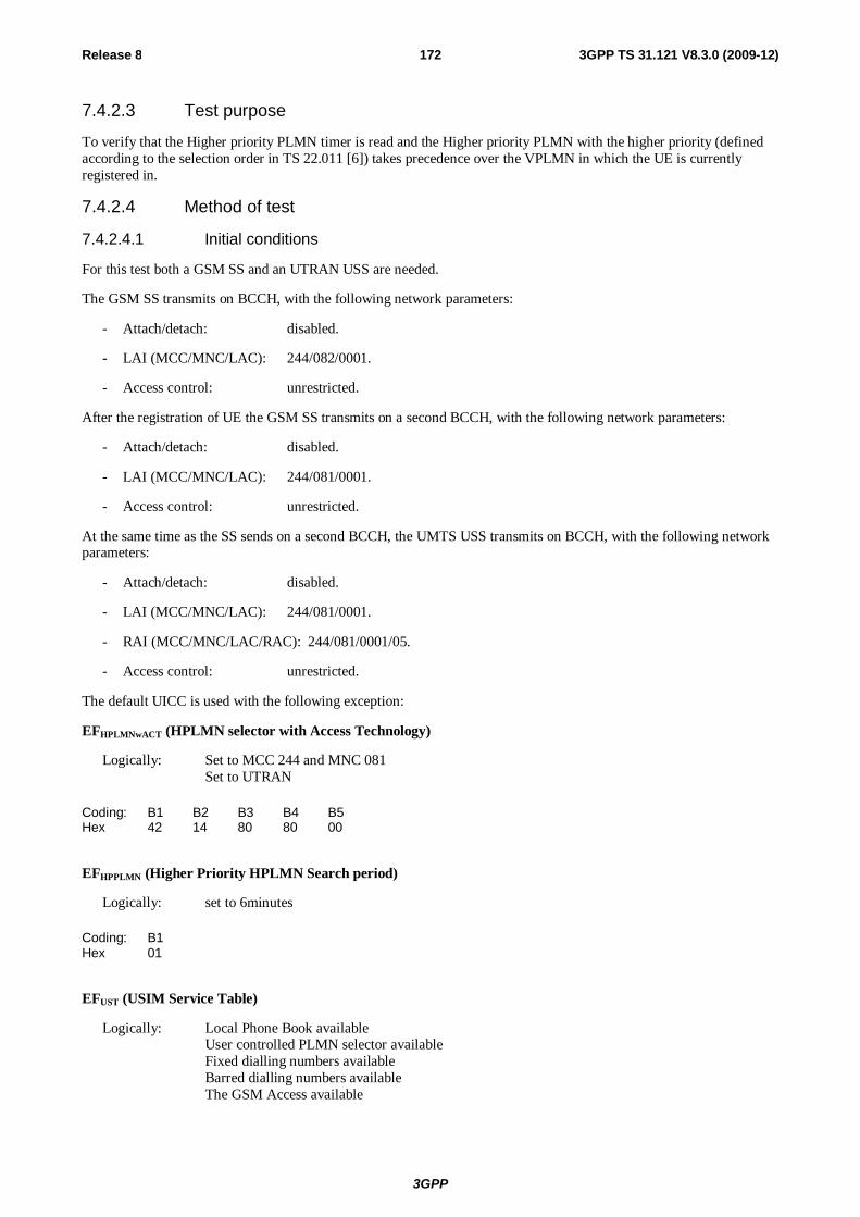
3GPP
Release 8 172 3GPP TS 31.121 V8.3.0 (2009-12)
7.4.2.3 Test purpose
To verify that the Higher priority PLMN timer is read and the Higher priority PLMN with the higher priority (defined according to the selection order in TS 22.011 [6]) takes precedence over the VPLMN in which the UE is currently registered in.
7.4.2.4 Method of test
7.4.2.4.1 Initial conditions
For this test both a GSM SS and an UTRAN USS are needed.
The GSM SS transmits on BCCH, with the following network parameters:
- Attach/detach: disabled.
- LAI (MCC/MNC/LAC): 244/082/0001.
- Access control: unrestricted.
After the registration of UE the GSM SS transmits on a second BCCH, with the following network parameters:
- Attach/detach: disabled.
- LAI (MCC/MNC/LAC): 244/081/0001.
- Access control: unrestricted.
At the same time as the SS sends on a second BCCH, the UMTS USS transmits on BCCH, with the following network parameters:
- Attach/detach: disabled.
- LAI (MCC/MNC/LAC): 244/081/0001.
- RAI (MCC/MNC/LAC/RAC): 244/081/0001/05.
- Access control: unrestricted.
The default UICC is used with the following exception:
EFHPLMNwACT (HPLMN selector with Access Technology)
Logically: Set to MCC 244 and MNC 081 Set to UTRAN
Coding: B1 B2 B3 B4 B5 Hex 42 14 80 80 00
EFHPPLMN (Higher Priority HPLMN Search period)
Logically: set to 6minutes
Coding: B1 Hex 01
EFUST (USIM Service Table)
Logically: Local Phone Book available User controlled PLMN selector available Fixed dialling numbers available Barred dialling numbers available The GSM Access available
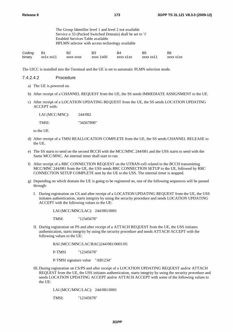
3GPP
Release 8 173 3GPP TS 31.121 V8.3.0 (2009-12)
The Group Identifier level 1 and level 2 not available Service n 33 (Packed Switched Domain) shall be set to '1' Enabled Services Table available
HPLMN selector with access technology available
Coding: B1 B2 B3 B4 B5 B6 binary xx1x xx11 xxxx xxxx xxxx 1x00 xxxx x1xx xxxx xx11 xxxx x1xx
The UICC is installed into the Terminal and the UE is set to automatic PLMN selection mode.
7.4.2.4.2 Procedure
a) The UE is powered on.
b) After receipt of a CHANNEL REQUEST from the UE, the SS sends IMMEDIATE ASSIGNMENT to the UE.
c) After receipt of a LOCATION UPDATING REQUEST from the UE, the SS sends LOCATION UPDATING ACCEPT with:
LAI (MCC/MNC): 244/082
TMSI: "34567890"
to the UE.
d) After receipt of a TMSI REALLOCATION COMPLETE from the UE, the SS sends CHANNEL RELEASE to the UE.
e) The SS starts to send on the second BCCH with the MCC/MNC 244/081 and the USS starts to send with the Same MCC/MNC. An internal timer shall start to run.
f) After receipt of a RRC CONNECTION REQUEST on the UTRAN-cell related to the BCCH transmitting MCC/MNC 244/081 from the UE, the USS sends RRC CONNECTION SETUP to the UE, followed by RRC CONNECTION SETUP COMPLETE sent by the UE to the USS. The internal timer is stopped.
g) Depending on which domain the UE is going to be registered on, one of the following sequences will be passed through:
I. During registration on CS and after receipt of a LOCATION UPDATING REQUEST from the UE, the USS initiates authentication, starts integrity by using the security procedure and sends LOCATION UPDATING ACCEPT with the following values to the UE:
LAI (MCC/MNC/LAC): 244/081/0001
TMSI: "12345678"
II. During registration on PS and after receipt of a ATTACH REQUEST from the UE, the USS initiates authentication, starts integrity by using the security procedure and sends ATTACH ACCEPT with the following values to the UE:
RAI (MCC/MNC/LAC/RAC) 244/081/0001/05
P-TMSI "12345678"
P-TMSI signature value "AB1234"
III. During registration on CS/PS and after receipt of a LOCATION UPDATING REQUEST and/or ATTACH REQUEST from the UE, the USS initiates authentication, starts integrity by using the security procedure and sends LOCATION UPDATING ACCEPT and/or ATTACH ACCEPT with some of the following values to the UE:
LAI (MCC/MNC/LAC): 244/081/0001
TMSI: "12345678"
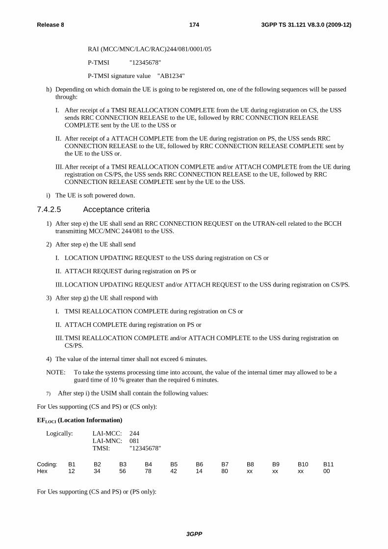
3GPP
Release 8 174 3GPP TS 31.121 V8.3.0 (2009-12)
RAI (MCC/MNC/LAC/RAC) 244/081/0001/05
P-TMSI "12345678"
P-TMSI signature value "AB1234"
h) Depending on which domain the UE is going to be registered on, one of the following sequences will be passed through:
I. After receipt of a TMSI REALLOCATION COMPLETE from the UE during registration on CS, the USS sends RRC CONNECTION RELEASE to the UE, followed by RRC CONNECTION RELEASE COMPLETE sent by the UE to the USS or
II. After receipt of a ATTACH COMPLETE from the UE during registration on PS, the USS sends RRC CONNECTION RELEASE to the UE, followed by RRC CONNECTION RELEASE COMPLETE sent by the UE to the USS or.
III. After receipt of a TMSI REALLOCATION COMPLETE and/or ATTACH COMPLETE from the UE during registration on CS/PS, the USS sends RRC CONNECTION RELEASE to the UE, followed by RRC CONNECTION RELEASE COMPLETE sent by the UE to the USS.
i) The UE is soft powered down.
7.4.2.5 Acceptance criteria
1) After step e) the UE shall send an RRC CONNECTION REQUEST on the UTRAN-cell related to the BCCH transmitting MCC/MNC 244/081 to the USS.
2) After step e) the UE shall send
I. LOCATION UPDATING REQUEST to the USS during registration on CS or
II. ATTACH REQUEST during registration on PS or
III. LOCATION UPDATING REQUEST and/or ATTACH REQUEST to the USS during registration on CS/PS.
3) After step g) the UE shall respond with
I. TMSI REALLOCATION COMPLETE during registration on CS or
II. ATTACH COMPLETE during registration on PS or
III. TMSI REALLOCATION COMPLETE and/or ATTACH COMPLETE to the USS during registration on CS/PS.
4) The value of the internal timer shall not exceed 6 minutes.
NOTE: To take the systems processing time into account, the value of the internal timer may allowed to be a guard time of 10 % greater than the required 6 minutes.
7) After step i) the USIM shall contain the following values:
For Ues supporting (CS and PS) or (CS only):
EFLOCI (Location Information)
Logically: LAI-MCC: 244 LAI-MNC: 081 TMSI: "12345678"
Coding: B1 B2 B3 B4 B5 B6 B7 B8 B9 B10 B11 Hex 12 34 56 78 42 14 80 xx xx xx 00
For Ues supporting (CS and PS) or (PS only):
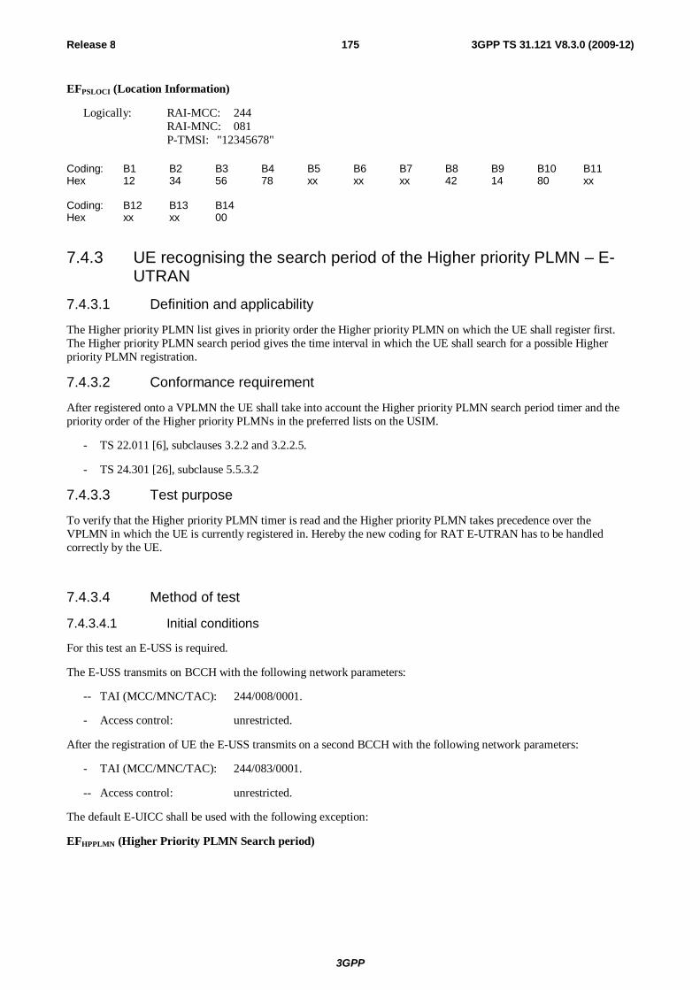
3GPP
Release 8 175 3GPP TS 31.121 V8.3.0 (2009-12)
EFPSLOCI (Location Information)
Logically: RAI-MCC: 244 RAI-MNC: 081 P-TMSI: "12345678"
Coding: B1 B2 B3 B4 B5 B6 B7 B8 B9 B10 B11 Hex 12 34 56 78 xx xx xx 42 14 80 xx Coding: B12 B13 B14 Hex xx xx 00
7.4.3 UE recognising the search period of the Higher priority PLMN – E-UTRAN
7.4.3.1 Definition and applicability
The Higher priority PLMN list gives in priority order the Higher priority PLMN on which the UE shall register first. The Higher priority PLMN search period gives the time interval in which the UE shall search for a possible Higher priority PLMN registration.
7.4.3.2 Conformance requirement
After registered onto a VPLMN the UE shall take into account the Higher priority PLMN search period timer and the priority order of the Higher priority PLMNs in the preferred lists on the USIM.
- TS 22.011 [6], subclauses 3.2.2 and 3.2.2.5.
- TS 24.301 [26], subclause 5.5.3.2
7.4.3.3 Test purpose
To verify that the Higher priority PLMN timer is read and the Higher priority PLMN takes precedence over the VPLMN in which the UE is currently registered in. Hereby the new coding for RAT E-UTRAN has to be handled correctly by the UE.
7.4.3.4 Method of test
7.4.3.4.1 Initial conditions
For this test an E-USS is required.
The E-USS transmits on BCCH with the following network parameters:
-- TAI (MCC/MNC/TAC): 244/008/0001.
- Access control: unrestricted.
After the registration of UE the E-USS transmits on a second BCCH with the following network parameters:
- TAI (MCC/MNC/TAC): 244/083/0001.
-- Access control: unrestricted.
The default E-UICC shall be used with the following exception:
EFHPPLMN (Higher Priority PLMN Search period)
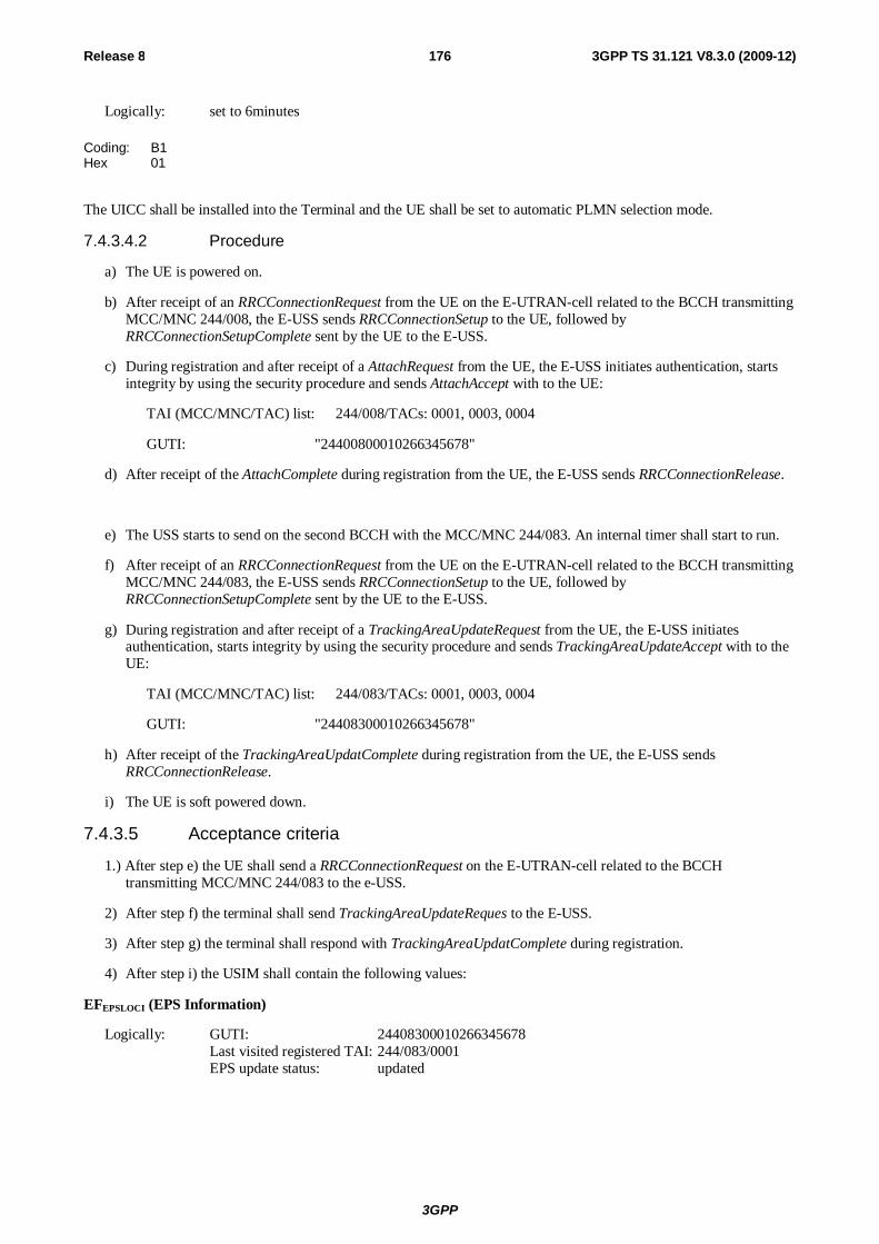
3GPP
Release 8 176 3GPP TS 31.121 V8.3.0 (2009-12)
Logically: set to 6minutes
Coding: B1 Hex 01
The UICC shall be installed into the Terminal and the UE shall be set to automatic PLMN selection mode.
7.4.3.4.2 Procedure
a) The UE is powered on.
b) After receipt of an RRCConnectionRequest from the UE on the E-UTRAN-cell related to the BCCH transmitting MCC/MNC 244/008, the E-USS sends RRCConnectionSetup to the UE, followed by RRCConnectionSetupComplete sent by the UE to the E-USS.
c) During registration and after receipt of a AttachRequest from the UE, the E-USS initiates authentication, starts integrity by using the security procedure and sends AttachAccept with to the UE:
TAI (MCC/MNC/TAC) list: 244/008/TACs: 0001, 0003, 0004
GUTI: "24400800010266345678"
d) After receipt of the AttachComplete during registration from the UE, the E-USS sends RRCConnectionRelease.
e) The USS starts to send on the second BCCH with the MCC/MNC 244/083. An internal timer shall start to run.
f) After receipt of an RRCConnectionRequest from the UE on the E-UTRAN-cell related to the BCCH transmitting MCC/MNC 244/083, the E-USS sends RRCConnectionSetup to the UE, followed by RRCConnectionSetupComplete sent by the UE to the E-USS.
g) During registration and after receipt of a TrackingAreaUpdateRequest from the UE, the E-USS initiates authentication, starts integrity by using the security procedure and sends TrackingAreaUpdateAccept with to the UE:
TAI (MCC/MNC/TAC) list: 244/083/TACs: 0001, 0003, 0004
GUTI: "24408300010266345678"
h) After receipt of the TrackingAreaUpdatComplete during registration from the UE, the E-USS sends RRCConnectionRelease.
i) The UE is soft powered down.
7.4.3.5 Acceptance criteria
1.) After step e) the UE shall send a RRCConnectionRequest on the E-UTRAN-cell related to the BCCH transmitting MCC/MNC 244/083 to the e-USS.
2) After step f) the terminal shall send TrackingAreaUpdateReques to the E-USS.
3) After step g) the terminal shall respond with TrackingAreaUpdatComplete during registration.
4) After step i) the USIM shall contain the following values:
EFEPSLOCI (EPS Information)
Logically: GUTI: 24408300010266345678 Last visited registered TAI: 244/083/0001 EPS update status: updated
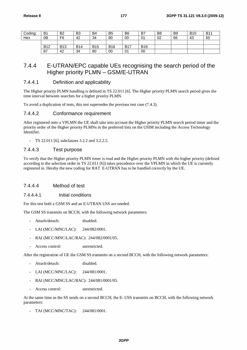
3GPP
Release 8 177 3GPP TS 31.121 V8.3.0 (2009-12)
Coding: B1 B2 B3 B4 B5 B6 B7 B8 B9 B10 B11 Hex 0B F6 42 34 80 00 01 02 66 43 65 B12 B13 B14 B15 B16 B17 B18 87 42 34 80 00 01 00
7.4.4 E-UTRAN/EPC capable UEs recognising the search period of the Higher priority PLMN – GSM/E-UTRAN
7.4.4.1 Definition and applicability
The Higher priority PLMN handling is defined in TS 22.011 [6]. The Higher priority PLMN search period gives the time interval between searches for a higher priority PLMN.
To avoid a duplication of tests, this test supersedes the previous test case (7.4.3).
7.4.4.2 Conformance requirement
After registered onto a VPLMN the UE shall take into account the Higher priority PLMN search period timer and the priority order of the Higher priority PLMNs in the preferred lists on the USIM including the Access Technology Identifier.
- TS 22.011 [6], subclauses 3.2.2 and 3.2.2.5.
7.4.4.3 Test purpose
To verify that the Higher priority PLMN timer is read and the Higher priority PLMN with the higher priority (defined according to the selection order in TS 22.011 [6]) takes precedence over the VPLMN in which the UE is currently registered in. Hereby the new coding for RAT E-UTRAN has to be handled correctly by the UE.
7.4.4.4 Method of test
7.4.4.4.1 Initial conditions
For this test both a GSM SS and an E-UTRAN USS are needed.
The GSM SS transmits on BCCH, with the following network parameters:
- Attach/detach: disabled.
- LAI (MCC/MNC/LAC): 244/082/0001.
- RAI (MCC/MNC/LAC/RAC): 244/082/0001/05.
- Access control: unrestricted.
After the registration of UE the GSM SS transmits on a second BCCH, with the following network parameters:
- Attach/detach: disabled.
- LAI (MCC/MNC/LAC): 244/081/0001.
- RAI (MCC/MNC/LAC/RAC): 244/081/0001/05.
- Access control: unrestricted.
At the same time as the SS sends on a second BCCH, the E- USS transmits on BCCH, with the following network parameters:
- TAI (MCC/MNC/TAC): 244/081/0001.
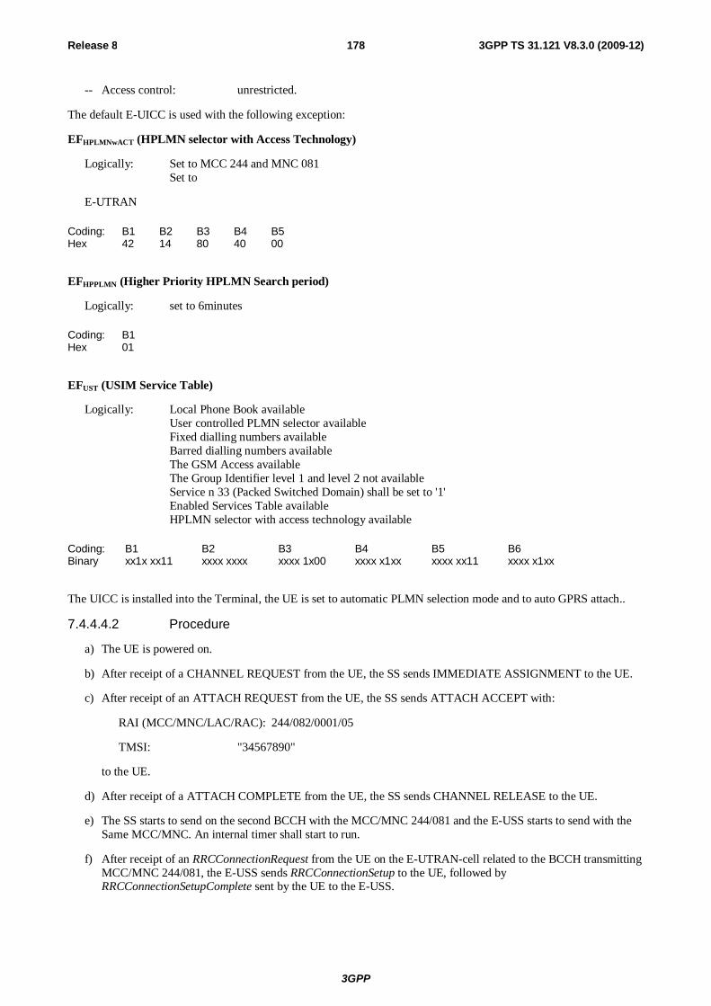
3GPP
Release 8 178 3GPP TS 31.121 V8.3.0 (2009-12)
-- Access control: unrestricted.
The default E-UICC is used with the following exception:
EFHPLMNwACT (HPLMN selector with Access Technology)
Logically: Set to MCC 244 and MNC 081 Set to
E-UTRAN
Coding: B1 B2 B3 B4 B5 Hex 42 14 80 40 00
EFHPPLMN (Higher Priority HPLMN Search period)
Logically: set to 6minutes
Coding: B1 Hex 01
EFUST (USIM Service Table)
Logically: Local Phone Book available User controlled PLMN selector available Fixed dialling numbers available Barred dialling numbers available The GSM Access available The Group Identifier level 1 and level 2 not available Service n 33 (Packed Switched Domain) shall be set to '1' Enabled Services Table available
HPLMN selector with access technology available
Coding: B1 B2 B3 B4 B5 B6 Binary xx1x xx11 xxxx xxxx xxxx 1x00 xxxx x1xx xxxx xx11 xxxx x1xx
The UICC is installed into the Terminal, the UE is set to automatic PLMN selection mode and to auto GPRS attach..
7.4.4.4.2 Procedure
a) The UE is powered on.
b) After receipt of a CHANNEL REQUEST from the UE, the SS sends IMMEDIATE ASSIGNMENT to the UE.
c) After receipt of an ATTACH REQUEST from the UE, the SS sends ATTACH ACCEPT with:
RAI (MCC/MNC/LAC/RAC): 244/082/0001/05
TMSI: "34567890"
to the UE.
d) After receipt of a ATTACH COMPLETE from the UE, the SS sends CHANNEL RELEASE to the UE.
e) The SS starts to send on the second BCCH with the MCC/MNC 244/081 and the E-USS starts to send with the Same MCC/MNC. An internal timer shall start to run.
f) After receipt of an RRCConnectionRequest from the UE on the E-UTRAN-cell related to the BCCH transmitting MCC/MNC 244/081, the E-USS sends RRCConnectionSetup to the UE, followed by RRCConnectionSetupComplete sent by the UE to the E-USS.
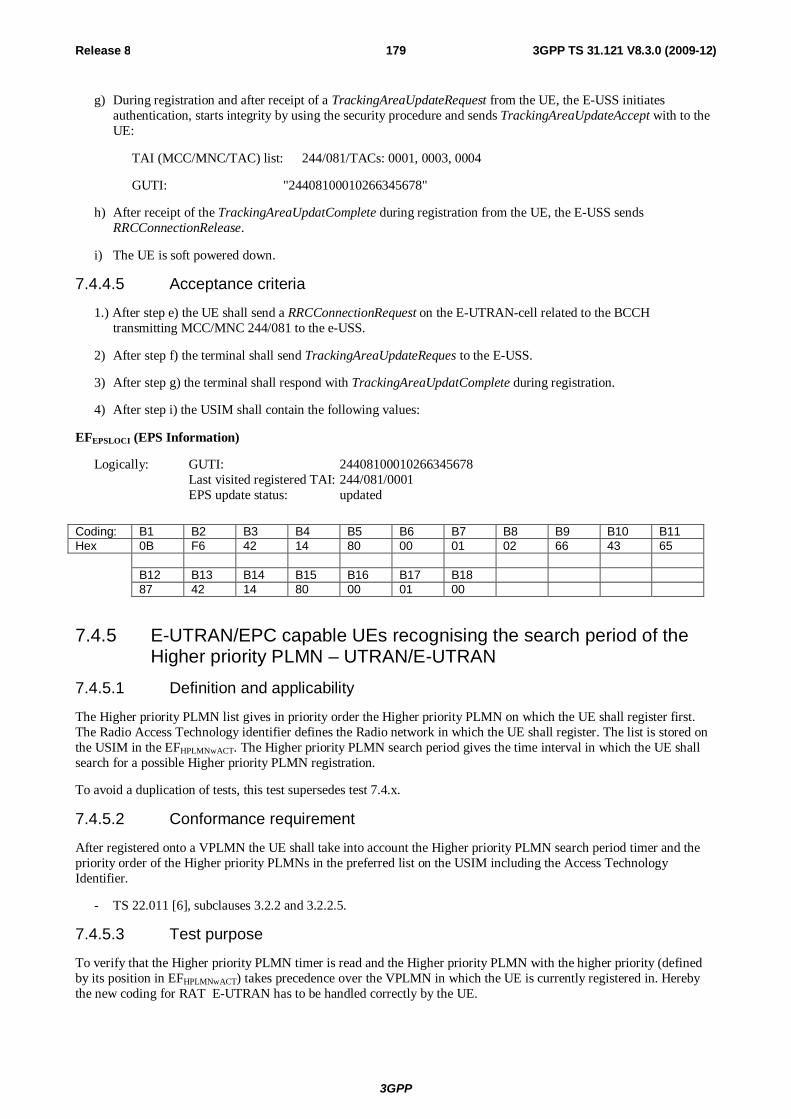
3GPP
Release 8 179 3GPP TS 31.121 V8.3.0 (2009-12)
g) During registration and after receipt of a TrackingAreaUpdateRequest from the UE, the E-USS initiates authentication, starts integrity by using the security procedure and sends TrackingAreaUpdateAccept with to the UE:
TAI (MCC/MNC/TAC) list: 244/081/TACs: 0001, 0003, 0004
GUTI: "24408100010266345678"
h) After receipt of the TrackingAreaUpdatComplete during registration from the UE, the E-USS sends RRCConnectionRelease.
i) The UE is soft powered down.
7.4.4.5 Acceptance criteria
1.) After step e) the UE shall send a RRCConnectionRequest on the E-UTRAN-cell related to the BCCH transmitting MCC/MNC 244/081 to the e-USS.
2) After step f) the terminal shall send TrackingAreaUpdateReques to the E-USS.
3) After step g) the terminal shall respond with TrackingAreaUpdatComplete during registration.
4) After step i) the USIM shall contain the following values:
EFEPSLOCI (EPS Information)
Logically: GUTI: 24408100010266345678 Last visited registered TAI: 244/081/0001 EPS update status: updated
Coding: B1 B2 B3 B4 B5 B6 B7 B8 B9 B10 B11 Hex 0B F6 42 14 80 00 01 02 66 43 65 B12 B13 B14 B15 B16 B17 B18 87 42 14 80 00 01 00
7.4.5 E-UTRAN/EPC capable UEs recognising the search period of the Higher priority PLMN – UTRAN/E-UTRAN
7.4.5.1 Definition and applicability
The Higher priority PLMN list gives in priority order the Higher priority PLMN on which the UE shall register first. The Radio Access Technology identifier defines the Radio network in which the UE shall register. The list is stored on the USIM in the EFHPLMNwACT. The Higher priority PLMN search period gives the time interval in which the UE shall search for a possible Higher priority PLMN registration.
To avoid a duplication of tests, this test supersedes test 7.4.x.
7.4.5.2 Conformance requirement
After registered onto a VPLMN the UE shall take into account the Higher priority PLMN search period timer and the priority order of the Higher priority PLMNs in the preferred list on the USIM including the Access Technology Identifier.
- TS 22.011 [6], subclauses 3.2.2 and 3.2.2.5.
7.4.5.3 Test purpose
To verify that the Higher priority PLMN timer is read and the Higher priority PLMN with the higher priority (defined by its position in EFHPLMNwACT) takes precedence over the VPLMN in which the UE is currently registered in. Hereby the new coding for RAT E-UTRAN has to be handled correctly by the UE.
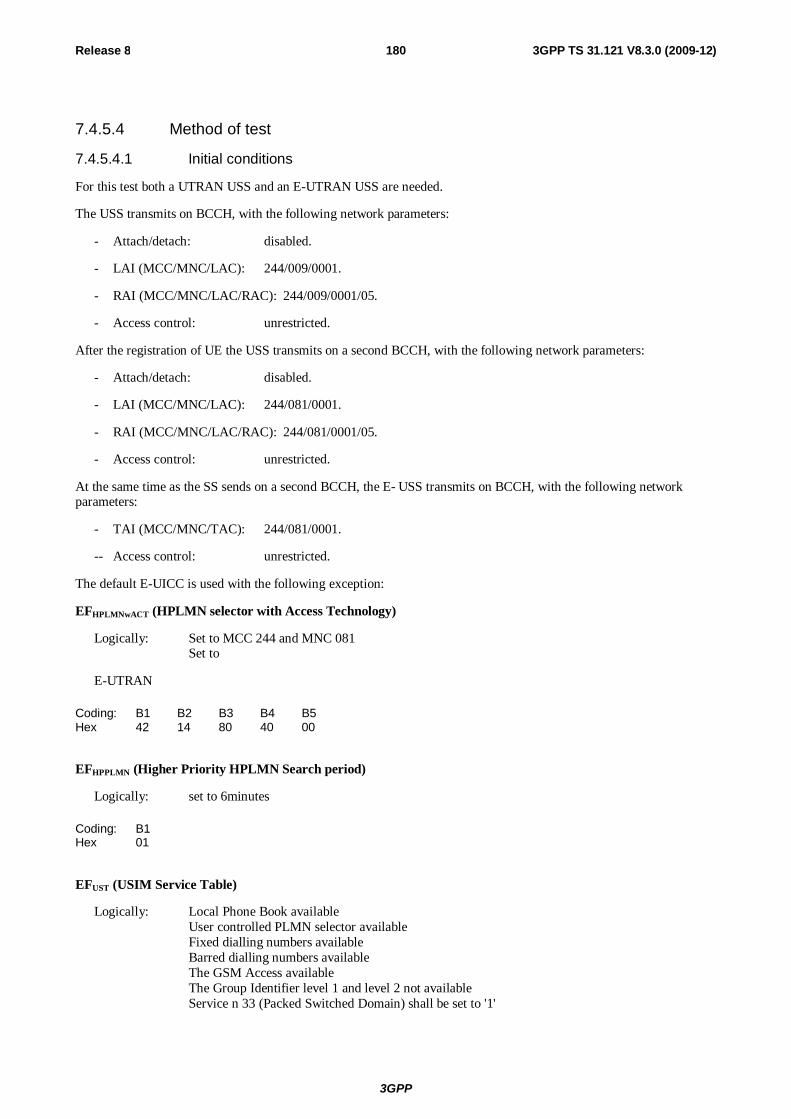
3GPP
Release 8 180 3GPP TS 31.121 V8.3.0 (2009-12)
7.4.5.4 Method of test
7.4.5.4.1 Initial conditions
For this test both a UTRAN USS and an E-UTRAN USS are needed.
The USS transmits on BCCH, with the following network parameters:
- Attach/detach: disabled.
- LAI (MCC/MNC/LAC): 244/009/0001.
- RAI (MCC/MNC/LAC/RAC): 244/009/0001/05.
- Access control: unrestricted.
After the registration of UE the USS transmits on a second BCCH, with the following network parameters:
- Attach/detach: disabled.
- LAI (MCC/MNC/LAC): 244/081/0001.
- RAI (MCC/MNC/LAC/RAC): 244/081/0001/05.
- Access control: unrestricted.
At the same time as the SS sends on a second BCCH, the E- USS transmits on BCCH, with the following network parameters:
- TAI (MCC/MNC/TAC): 244/081/0001.
-- Access control: unrestricted.
The default E-UICC is used with the following exception:
EFHPLMNwACT (HPLMN selector with Access Technology)
Logically: Set to MCC 244 and MNC 081 Set to
E-UTRAN
Coding: B1 B2 B3 B4 B5 Hex 42 14 80 40 00
EFHPPLMN (Higher Priority HPLMN Search period)
Logically: set to 6minutes
Coding: B1 Hex 01
EFUST (USIM Service Table)
Logically: Local Phone Book available User controlled PLMN selector available Fixed dialling numbers available Barred dialling numbers available The GSM Access available The Group Identifier level 1 and level 2 not available Service n 33 (Packed Switched Domain) shall be set to '1'

3GPP
Release 8 181 3GPP TS 31.121 V8.3.0 (2009-12)
Enabled Services Table available HPLMN selector with access technology available
Coding: B1 B2 B3 B4 B5 B6 Binary xx1x xx11 xxxx xxxx xxxx 1x00 xxxx x1xx xxxx xx11 xxxx x1xx
The UICC is installed into the Terminal, the UE is set to automatic PLMN selection mode and to auto GPRS attach.
7.4.5.4.2 Procedure
a) The UE is powered on.
b) After receipt of a RRC CONNECTION REQUEST from the UE, the USS shall send RRC CONNECTION SETUP to the UE, followed by RRC CONNECTION SETUP COMPLETE sent by the UE to the USS.
c) After receipt of an ATTACH REQUEST from the UE, the SS sends ATTACH ACCEPT with:
RAI (MCC/MNC/LAC/RAC): 244/009/0001/05
TMSI: "34567890"
to the UE.
d) After receipt of a ATTACH COMPLETE from the UE, the USS sends RRC CONNECTION RELEASE to the UE, followed by RRC CONNECTION RELEASE COMPLETE sent by the UE to the USS.
e) TheUSS starts to send on the second BCCH with the MCC/MNC 244/081 and the E-USS starts to send with the Same MCC/MNC. An internal timer shall start to run.
f) After receipt of an RRCConnectionRequest from the UE on the E-UTRAN-cell related to the BCCH transmitting MCC/MNC 244/081, the E-USS sends RRCConnectionSetup to the UE, followed by RRCConnectionSetupComplete sent by the UE to the E-USS.
g) During registration and after receipt of a TrackingAreaUpdateRequest from the UE, the E-USS initiates authentication, starts integrity by using the security procedure and sends TrackingAreaUpdateAccept with to the UE:
TAI (MCC/MNC/TAC) list: 244/081/TACs: 0001, 0003, 0004
GUTI: "24408100010266345678"
h) After receipt of the TrackingAreaUpdatComplete during registration from the UE, the E-USS sends RRCConnectionRelease.
i) The UE is soft powered down.
7.4.5.5 Acceptance criteria
1.) After step e) the UE shall send a RRCConnectionRequest on the E-UTRAN-cell related to the BCCH transmitting MCC/MNC 244/081 to the e-USS.
2) After step f) the terminal shall send TrackingAreaUpdateReques to the E-USS.
3) After step g) the terminal shall respond with TrackingAreaUpdatComplete during registration.
4) After step i) the USIM shall contain the following values:
EFEPSLOCI (EPS Information)
Logically: GUTI: 24408100010266345678 Last visited registered TAI: 244/081/0001 EPS update status: updated

3GPP
Release 8 182 3GPP TS 31.121 V8.3.0 (2009-12)
Coding: B1 B2 B3 B4 B5 B6 B7 B8 B9 B10 B11 Hex 0B F6 42 14 80 00 01 02 66 43 65 B12 B13 B14 B15 B16 B17 B18 87 42 14 80 00 01 00
7.5 Void
8 Subscription independent tests 8.1 Phone book procedures 8.1.1 Recognition of a previously changed phonebook 8.1.1.1 Definition and applicability
If the UICC is inserted into a GERAN Rel-4 or earlier terminal, the phonebook may have been altered in this GSM session. If the ADN entry has been changed or deleted, the GSM terminal will not be able to change the appropriate additional phonebook entries (e.g. EFANR Additional Number). In that case the UICC shall set a flag in the appropriate EFPBC (phonebook Control). If the UICC is inserted in a 3G or GERAN Terminal, the 3G or GERAN Terminal shall recognise the flag and the phonebook shall be synchronised by the Terminal. Once the Terminal recognise the set flag in the EFPBC, the Terminal shall update the Change Counter in the EFCC.
8.1.1.2 Conformance requirement
The 3G or GERAN Terminal shall recognise the set flag in the EFPBC and then synchronise the phonebook. The Terminal shall also update EFCC (Change Counter).
- TS 31.102 [4], subclause 4.4.2.
8.1.1.3 Test purpose
1) To verify that the Terminal has recognised that the phonebook has been altered by a GSM Terminal.
2) To verify that the Terminal does the synchronising of the changed phonebook entries.
3) To verify that the Terminal updates the EFPBC and EFCC.
8.1.1.4 Method of test
8.1.1.4.1 Initial conditions
No USS is needed for this test.
The default UICC is used with the following exception:
EFADN (Abbreviated Dialling Number)
Logically: Record 1: Length of alpha identifier: 32 characters; Alpha identifier: "ABCDEFGHIJKLMNOPQRSTUVWXYZABCDEF"; Length of BCD number: "03"; TON and NPI: Telephony and Unknown; Dialled number: 123; CCI: None; Ext1: None.
Record 1:
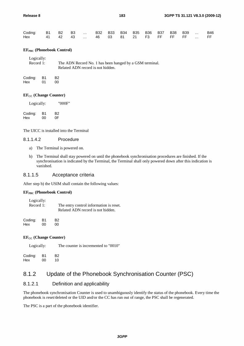
3GPP
Release 8 183 3GPP TS 31.121 V8.3.0 (2009-12)
Coding: B1 B2 B3 … B32 B33 B34 B35 B36 B37 B38 B39 … B46 Hex 41 42 43 … 46 03 81 21 F3 FF FF FF … FF
EFPBC (Phonebook Control)
Logically: Record 1: The ADN Record No. 1 has been hanged by a GSM terminal. Related ADN record is not hidden.
Coding: B1 B2 Hex 01 00
EFCC (Change Counter)
Logically: "000F"
Coding: B1 B2 Hex 00 0F
The UICC is installed into the Terminal
8.1.1.4.2 Procedure
a) The Terminal is powered on.
b) The Terminal shall stay powered on until the phonebook synchronisation procedures are finished. If the synchronisation is indicated by the Terminal, the Terminal shall only powered down after this indication is vanished.
8.1.1.5 Acceptance criteria
After step b) the USIM shall contain the following values:
EFPBC (Phonebook Control)
Logically: Record 1: The entry control information is reset. Related ADN record is not hidden.
Coding: B1 B2 Hex 00 00
EFCC (Change Counter)
Logically: The counter is incremented to "0010"
Coding: B1 B2 Hex 00 10
8.1.2 Update of the Phonebook Synchronisation Counter (PSC)
8.1.2.1 Definition and applicability
The phonebook synchronisation Counter is used to unambiguously identify the status of the phonebook. Every time the phonebook is reset/deleted or the UID and/or the CC has run out of range, the PSC shall be regenerated.
The PSC is a part of the phonebook identifier.
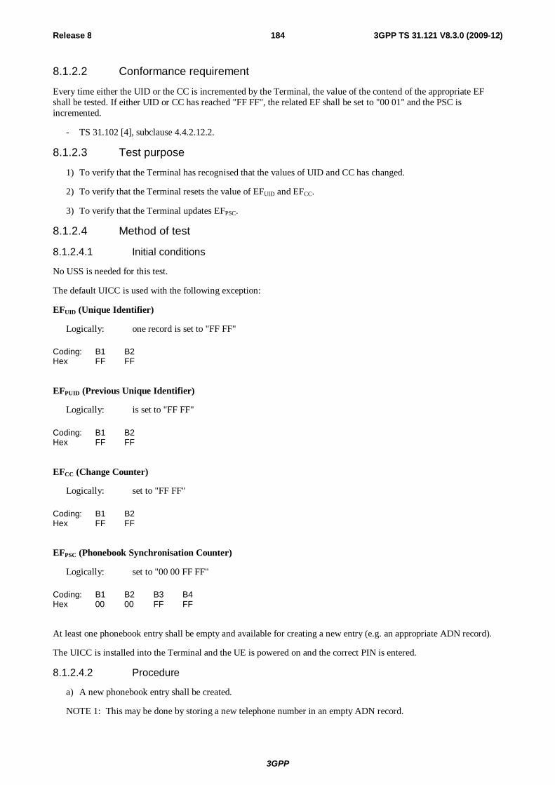
3GPP
Release 8 184 3GPP TS 31.121 V8.3.0 (2009-12)
8.1.2.2 Conformance requirement
Every time either the UID or the CC is incremented by the Terminal, the value of the contend of the appropriate EF shall be tested. If either UID or CC has reached "FF FF", the related EF shall be set to "00 01" and the PSC is incremented.
- TS 31.102 [4], subclause 4.4.2.12.2.
8.1.2.3 Test purpose
1) To verify that the Terminal has recognised that the values of UID and CC has changed.
2) To verify that the Terminal resets the value of EFUID and EFCC.
3) To verify that the Terminal updates EFPSC.
8.1.2.4 Method of test
8.1.2.4.1 Initial conditions
No USS is needed for this test.
The default UICC is used with the following exception:
EFUID (Unique Identifier)
Logically: one record is set to "FF FF"
Coding: B1 B2 Hex FF FF
EFPUID (Previous Unique Identifier)
Logically: is set to "FF FF"
Coding: B1 B2 Hex FF FF
EFCC (Change Counter)
Logically: set to "FF FF"
Coding: B1 B2 Hex FF FF
EFPSC (Phonebook Synchronisation Counter)
Logically: set to "00 00 FF FF"
Coding: B1 B2 B3 B4 Hex 00 00 FF FF
At least one phonebook entry shall be empty and available for creating a new entry (e.g. an appropriate ADN record).
The UICC is installed into the Terminal and the UE is powered on and the correct PIN is entered.
8.1.2.4.2 Procedure
a) A new phonebook entry shall be created.
NOTE 1: This may be done by storing a new telephone number in an empty ADN record.
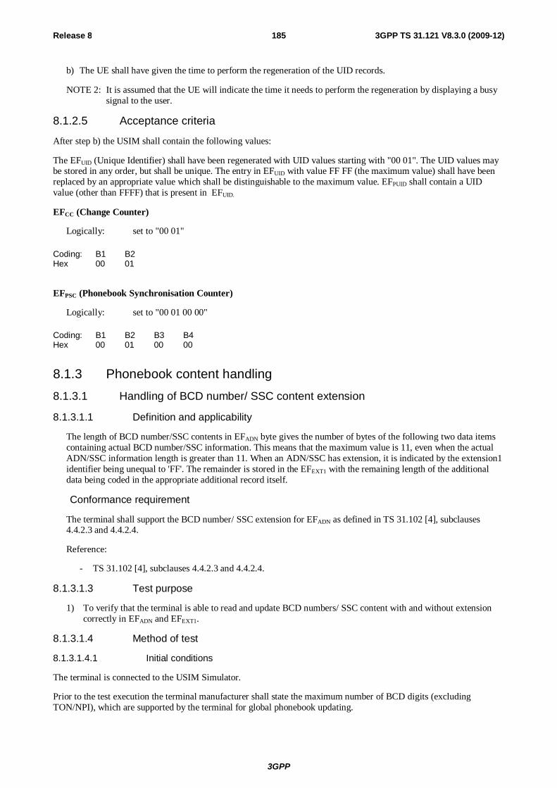
3GPP
Release 8 185 3GPP TS 31.121 V8.3.0 (2009-12)
b) The UE shall have given the time to perform the regeneration of the UID records.
NOTE 2: It is assumed that the UE will indicate the time it needs to perform the regeneration by displaying a busy signal to the user.
8.1.2.5 Acceptance criteria
After step b) the USIM shall contain the following values:
The EFUID (Unique Identifier) shall have been regenerated with UID values starting with "00 01". The UID values may be stored in any order, but shall be unique. The entry in EFUID with value FF FF (the maximum value) shall have been replaced by an appropriate value which shall be distinguishable to the maximum value. EFPUID shall contain a UID value (other than FFFF) that is present in EFUID.
EFCC (Change Counter)
Logically: set to "00 01"
Coding: B1 B2 Hex 00 01
EFPSC (Phonebook Synchronisation Counter)
Logically: set to "00 01 00 00"
Coding: B1 B2 B3 B4 Hex 00 01 00 00
8.1.3 Phonebook content handling 8.1.3.1 Handling of BCD number/ SSC content extension
8.1.3.1.1 Definition and applicability
The length of BCD number/SSC contents in EFADN byte gives the number of bytes of the following two data items containing actual BCD number/SSC information. This means that the maximum value is 11, even when the actual ADN/SSC information length is greater than 11. When an ADN/SSC has extension, it is indicated by the extension1 identifier being unequal to 'FF'. The remainder is stored in the EFEXT1 with the remaining length of the additional data being coded in the appropriate additional record itself.
Conformance requirement
The terminal shall support the BCD number/ SSC extension for EFADN as defined in TS 31.102 [4], subclauses 4.4.2.3 and 4.4.2.4.
Reference:
- TS 31.102 [4], subclauses 4.4.2.3 and 4.4.2.4.
8.1.3.1.3 Test purpose
1) To verify that the terminal is able to read and update BCD numbers/ SSC content with and without extension correctly in EFADN and EFEXT1.
8.1.3.1.4 Method of test
8.1.3.1.4.1 Initial conditions
The terminal is connected to the USIM Simulator.
Prior to the test execution the terminal manufacturer shall state the maximum number of BCD digits (excluding TON/NPI), which are supported by the terminal for global phonebook updating.
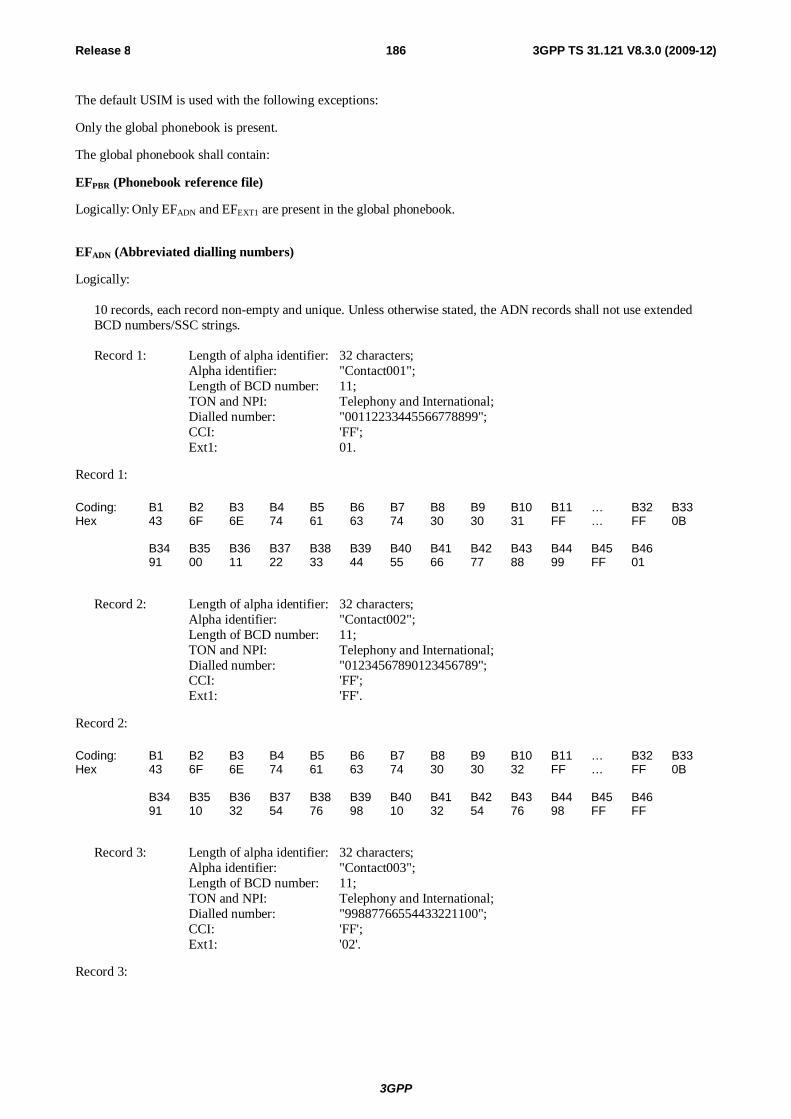
3GPP
Release 8 186 3GPP TS 31.121 V8.3.0 (2009-12)
The default USIM is used with the following exceptions:
Only the global phonebook is present.
The global phonebook shall contain:
EFPBR (Phonebook reference file)
Logically: Only EFADN and EFEXT1 are present in the global phonebook.
EFADN (Abbreviated dialling numbers)
Logically:
10 records, each record non-empty and unique. Unless otherwise stated, the ADN records shall not use extended BCD numbers/SSC strings. Record 1: Length of alpha identifier: 32 characters; Alpha identifier: "Contact001"; Length of BCD number: 11; TON and NPI: Telephony and International; Dialled number: "00112233445566778899"; CCI: 'FF'; Ext1: 01.
Record 1:
Coding: B1 B2 B3 B4 B5 B6 B7 B8 B9 B10 B11 … B32 B33 Hex 43 6F 6E 74 61 63 74 30 30 31 FF … FF 0B B34 B35 B36 B37 B38 B39 B40 B41 B42 B43 B44 B45 B46 91 00 11 22 33 44 55 66 77 88 99 FF 01
Record 2: Length of alpha identifier: 32 characters; Alpha identifier: "Contact002"; Length of BCD number: 11; TON and NPI: Telephony and International; Dialled number: "01234567890123456789"; CCI: 'FF'; Ext1: 'FF'.
Record 2:
Coding: B1 B2 B3 B4 B5 B6 B7 B8 B9 B10 B11 … B32 B33 Hex 43 6F 6E 74 61 63 74 30 30 32 FF … FF 0B B34 B35 B36 B37 B38 B39 B40 B41 B42 B43 B44 B45 B46 91 10 32 54 76 98 10 32 54 76 98 FF FF
Record 3: Length of alpha identifier: 32 characters; Alpha identifier: "Contact003"; Length of BCD number: 11; TON and NPI: Telephony and International; Dialled number: "99887766554433221100"; CCI: 'FF'; Ext1: '02'.
Record 3:
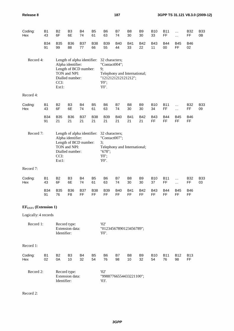
3GPP
Release 8 187 3GPP TS 31.121 V8.3.0 (2009-12)
Coding: B1 B2 B3 B4 B5 B6 B7 B8 B9 B10 B11 … B32 B33 Hex 43 6F 6E 74 61 63 74 30 30 33 FF … FF 0B B34 B35 B36 B37 B38 B39 B40 B41 B42 B43 B44 B45 B46 91 99 88 77 66 55 44 33 22 11 00 FF 02
Record 4: Length of alpha identifier: 32 characters; Alpha identifier: "Contact004"; Length of BCD number: 9; TON and NPI: Telephony and International; Dialled number: "1212121212121212"; CCI: 'FF'; Ext1: 'FF'.
Record 4:
Coding: B1 B2 B3 B4 B5 B6 B7 B8 B9 B10 B11 … B32 B33 Hex 43 6F 6E 74 61 63 74 30 30 34 FF … FF 09 B34 B35 B36 B37 B38 B39 B40 B41 B42 B43 B44 B45 B46 91 21 21 21 21 21 21 21 21 FF FF FF FF
Record 7: Length of alpha identifier: 32 characters; Alpha identifier: "Contact007"; Length of BCD number: 3; TON and NPI: Telephony and International; Dialled number: "678"; CCI: 'FF'; Ext1: 'FF'.
Record 7:
Coding: B1 B2 B3 B4 B5 B6 B7 B8 B9 B10 B11 … B32 B33 Hex 43 6F 6E 74 61 63 74 30 30 37 FF … FF 03 B34 B35 B36 B37 B38 B39 B40 B41 B42 B43 B44 B45 B46 91 76 F8 FF FF FF FF FF FF FF FF FF FF
EFEXT1 (Extension 1)
Logically: 4 records Record 1: Record type: '02' Extension data: "01234567890123456789"; Identifier: 'FF'.
Record 1:
Coding: B1 B2 B3 B4 B5 B6 B7 B8 B9 B10 B11 B12 B13 Hex 02 0A 10 32 54 76 98 10 32 54 76 98 FF
Record 2: Record type: '02' Extension data: "99887766554433221100"; Identifier: '03'.
Record 2:
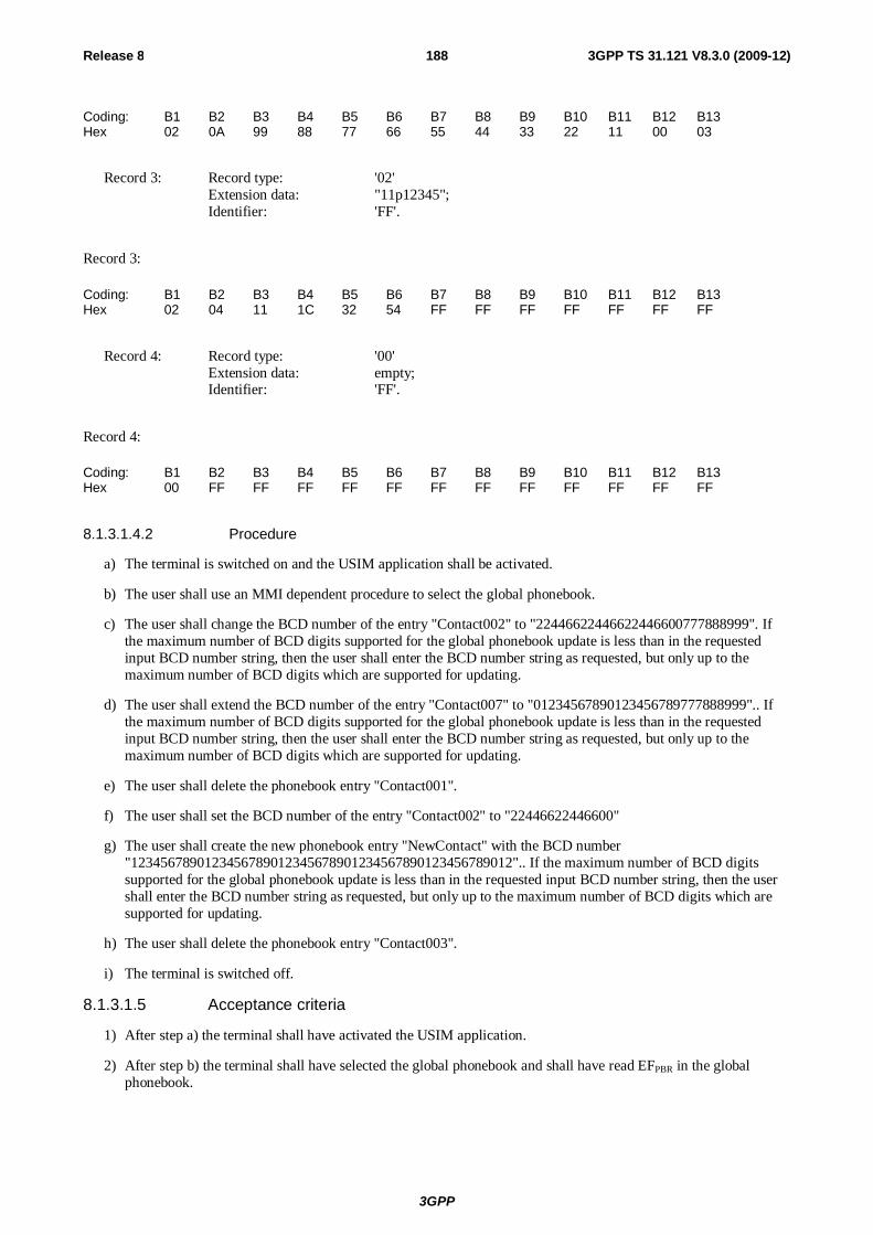
3GPP
Release 8 188 3GPP TS 31.121 V8.3.0 (2009-12)
Coding: B1 B2 B3 B4 B5 B6 B7 B8 B9 B10 B11 B12 B13 Hex 02 0A 99 88 77 66 55 44 33 22 11 00 03
Record 3: Record type: '02' Extension data: "11p12345"; Identifier: 'FF'.
Record 3:
Coding: B1 B2 B3 B4 B5 B6 B7 B8 B9 B10 B11 B12 B13 Hex 02 04 11 1C 32 54 FF FF FF FF FF FF FF
Record 4: Record type: '00' Extension data: empty; Identifier: 'FF'.
Record 4:
Coding: B1 B2 B3 B4 B5 B6 B7 B8 B9 B10 B11 B12 B13 Hex 00 FF FF FF FF FF FF FF FF FF FF FF FF
8.1.3.1.4.2 Procedure
a) The terminal is switched on and the USIM application shall be activated.
b) The user shall use an MMI dependent procedure to select the global phonebook.
c) The user shall change the BCD number of the entry "Contact002" to "22446622446622446600777888999". If the maximum number of BCD digits supported for the global phonebook update is less than in the requested input BCD number string, then the user shall enter the BCD number string as requested, but only up to the maximum number of BCD digits which are supported for updating.
d) The user shall extend the BCD number of the entry "Contact007" to "01234567890123456789777888999".. If the maximum number of BCD digits supported for the global phonebook update is less than in the requested input BCD number string, then the user shall enter the BCD number string as requested, but only up to the maximum number of BCD digits which are supported for updating.
e) The user shall delete the phonebook entry "Contact001".
f) The user shall set the BCD number of the entry "Contact002" to "22446622446600"
g) The user shall create the new phonebook entry "NewContact" with the BCD number "1234567890123456789012345678901234567890123456789012".. If the maximum number of BCD digits supported for the global phonebook update is less than in the requested input BCD number string, then the user shall enter the BCD number string as requested, but only up to the maximum number of BCD digits which are supported for updating.
h) The user shall delete the phonebook entry "Contact003".
i) The terminal is switched off.
8.1.3.1.5 Acceptance criteria
1) After step a) the terminal shall have activated the USIM application.
2) After step b) the terminal shall have selected the global phonebook and shall have read EFPBR in the global phonebook.
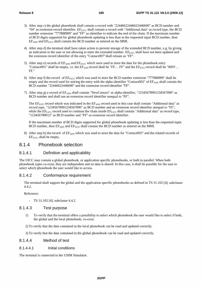
3GPP
Release 8 189 3GPP TS 31.121 V8.3.0 (2009-12)
3) After step c) the global phonebook shall contain a record with "22446622446622446600" as BCD number and "04" as extension record identifier. EFEXT1 shall contain a record with "Additional data" as record type, the BCD number extension "777888999" and "FF" as identifier to indicate the end of the chain. If the maximum number of BCD digits supported for global phonebook updating is less than in the requested input BCD number, then EFADN and EFEXT1 shall contain the BCD number as entered on the MMI.
4) After step d) the terminal shall have taken action to prevent storage of the extended BCD number, e.g. by giving an indication to the user or not allowing to enter the extended number. EFEXT1 shall have not been updated and the extension record identifier of the entry "Contact007"shall remain as "FF".
5) After step e) records of EFADN and EFEXT1 which were used to store the data for the phonebook entry "Contact001" shall be empty, i.e. the EFADN record shall be "FF… FF" and the EFEXT1 record shall be "00FF… FF."
6) After step f) the record of EFEXT1 which was used to store the BCD number extension "777888999" shall be empty and the record used for storing the entry with the alpha identifier "Contact002" of EFADN shall contain the BCD number "22446622446600" and the extension record identifier "FF".
7) After step g) a record of EFADN shall contain "NewContact" as alpha identifier, "12345678901234567890" as BCD number and shall use an extension record identifier unequal to "FF".
The EFEXT1 record which was indicated in the EFADN record used in this case shall contain "Additional data" as record type, "12345678901234567890" as BCD number and an extension record identifier unequal to "FF", while the EFEXT1 record used to continue the chain inside EFEXT1 shall contain "Additional data" as record type, "123456789012" as BCD number and "FF" as extension record identifier.
If the maximum number of BCD digits supported for global phonebook updating is less than the requested input BCD number, then EFADN and EFEXT1 shall contain the BCD number as entered on the MMI.
8) After step h) the record of EFADN which was used to store the data for "Contact003" and the related records of EFEXT1 shall be empty.
8.1.4 Phonebook selection
8.1.4.1 Definition and applicability
The UICC may contain a global phonebook, or application specific phonebooks, or both in parallel. When both phonebook types co-exist, they are independent and no data is shared. In this case, it shall be possible for the user to select which phonebook the user would like to access.
8.1.4.2 Conformance requirement
The terminal shall support the global and the application specific phonebooks as defined in TS 31.102 [4], subclause 4.4.2.
Reference:
- TS 31.102 [4], subclause 4.4.2.
8.1.4.3 Test purpose
1) To verify that the terminal offers a possibility to select which phonebook the user would like to select if both, the global and the local phonebook, co-exist.
2) To verify that the data contained in the local phonebook can be read and updated correctly.
3) To verify that the data contained in the global phonebook can be read and updated correctly.
8.1.4.4 Method of test
8.1.4.4.1 Initial conditions
The terminal is connected to the USIM Simulator.
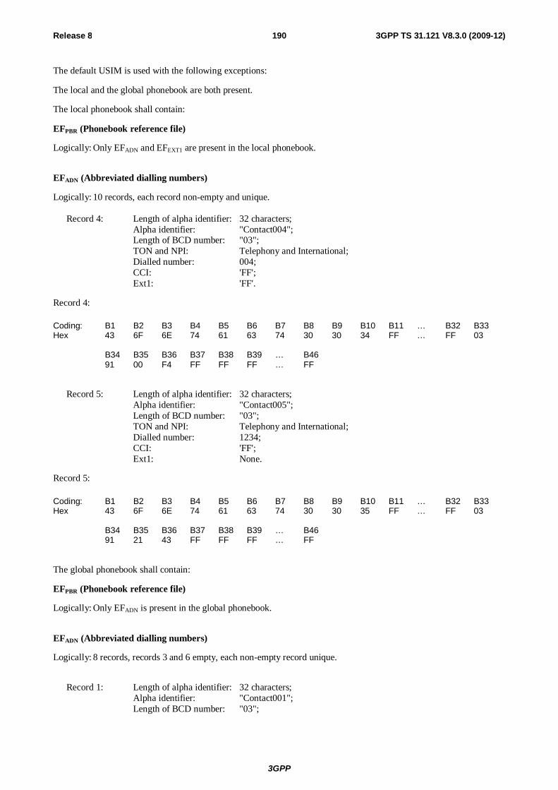
3GPP
Release 8 190 3GPP TS 31.121 V8.3.0 (2009-12)
The default USIM is used with the following exceptions:
The local and the global phonebook are both present.
The local phonebook shall contain:
EFPBR (Phonebook reference file)
Logically: Only EFADN and EFEXT1 are present in the local phonebook.
EFADN (Abbreviated dialling numbers)
Logically: 10 records, each record non-empty and unique. Record 4: Length of alpha identifier: 32 characters; Alpha identifier: "Contact004"; Length of BCD number: "03"; TON and NPI: Telephony and International; Dialled number: 004; CCI: 'FF'; Ext1: 'FF'.
Record 4:
Coding: B1 B2 B3 B4 B5 B6 B7 B8 B9 B10 B11 … B32 B33 Hex 43 6F 6E 74 61 63 74 30 30 34 FF … FF 03 B34 B35 B36 B37 B38 B39 … B46 91 00 F4 FF FF FF … FF
Record 5: Length of alpha identifier: 32 characters; Alpha identifier: "Contact005"; Length of BCD number: "03"; TON and NPI: Telephony and International; Dialled number: 1234; CCI: 'FF'; Ext1: None.
Record 5:
Coding: B1 B2 B3 B4 B5 B6 B7 B8 B9 B10 B11 … B32 B33 Hex 43 6F 6E 74 61 63 74 30 30 35 FF … FF 03 B34 B35 B36 B37 B38 B39 … B46 91 21 43 FF FF FF … FF
The global phonebook shall contain:
EFPBR (Phonebook reference file)
Logically: Only EFADN is present in the global phonebook.
EFADN (Abbreviated dialling numbers)
Logically: 8 records, records 3 and 6 empty, each non-empty record unique.
Record 1: Length of alpha identifier: 32 characters; Alpha identifier: "Contact001"; Length of BCD number: "03";

3GPP
Release 8 191 3GPP TS 31.121 V8.3.0 (2009-12)
TON and NPI: Telephony and International; Dialled number: 001; CCI: 'FF'; Ext1: 'FF'.
Record 1:
Coding: B1 B2 B3 B4 B5 B6 B7 B8 B9 B10 B11 … B32 B33 Hex 43 6F 6E 74 61 63 74 30 30 31 FF … FF 03 B34 B35 B36 B37 B38 B39 … B46 91 00 F1 FF FF FF … FF
Record 2: Length of alpha identifier: 32 characters; Alpha identifier: "Contact002"; Length of BCD number: "03"; TON and NPI: Telephony and International; Dialled number: 002; CCI: 'FF'; Ext1: 'FF'.
Record 2:
Coding: B1 B2 B3 B4 B5 B6 B7 B8 B9 B10 B11 … B32 B33 Hex 43 6F 6E 74 61 63 74 30 30 32 FF … FF 03 B34 B35 B36 B37 B38 B39 … B46 91 00 F2 FF FF FF … FF
Record 4: Length of alpha identifier: 32 characters; Alpha identifier: "Contact004"; Length of BCD number: "03"; TON and NPI: Telephony and International; Dialled number: 0041; CCI: 'FF'; Ext1: 'FF'.
Record 4:
Coding: B1 B2 B3 B4 B5 B6 B7 B8 B9 B10 B11 … B32 B33 Hex 43 6F 6E 74 61 63 74 30 30 34 FF … FF 03 B34 B35 B36 B37 B38 B39 … B46 91 00 14 FF FF FF … FF
Record 5: Length of alpha identifier: 32 characters; Alpha identifier: "Contact005"; Length of BCD number: "03"; TON and NPI: Telephony and International; Dialled number: 1234; CCI: 'FF'; Ext1: 'FF'.
Record 5:

3GPP
Release 8 192 3GPP TS 31.121 V8.3.0 (2009-12)
Coding: B1 B2 B3 B4 B5 B6 B7 B8 B9 B10 B11 … B32 B33 Hex 43 6F 6E 74 61 63 74 30 30 35 FF … FF 03 B34 B35 B36 B37 B38 B39 … B46 91 21 43 FF FF FF … FF
Record 7: Length of alpha identifier: 32 characters; Alpha identifier: "Contact007"; Length of BCD number: "03"; TON and NPI: Telephony and International; Dialled number: 007; CCI: 'FF'; Ext1: 'FF'.
Record 7:
Coding: B1 B2 B3 B4 B5 B6 B7 B8 B9 B10 B11 … B32 B33 Hex 43 6F 6E 74 61 63 74 30 30 37 FF … FF 03 B34 B35 B36 B37 B38 B39 … B46 91 00 F7 FF FF FF … FF
Record 8: Length of alpha identifier: 32 characters; Alpha identifier: "Contact008"; Length of BCD number: "03"; TON and NPI: Telephony and International; Dialled number: 008; CCI: 'FF'; Ext1: 'FF'.
Record 8:
Coding: B1 B2 B3 B4 B5 B6 B7 B8 B9 B10 B11 … B32 B33 Hex 43 6F 6E 74 61 63 74 30 30 38 FF … FF 03 B34 B35 B36 B37 B38 B39 … B46 91 00 F8 FF FF FF … FF
8.1.4.4.2 Procedure
a) The terminal is switched on and the USIM application shall be activated.
b) The user shall use an MMI dependent procedure to select the global phonebook.
c) The global phonebook record with the alpha identifier "Contact005" and the associated dialling number shall be read by the user.
d) The dialling number of the global phonebook record with the alpha identifier "Contact005" shall be set to "+1122330".
e) A new entry with the values "Contact006" as alpha identifier and "+9876543210" as associated dialling number shall be added to the global phonebook.
f) The user shall use an MMI dependent procedure to select the local phonebook.
g) The local phonebook record with the alpha identifier "Contact005" and the associated dialling number shall be read by the user.
h) The dialling number of the local phonebook record with the alpha identifier "Contact005" shall be set to "+11223345".
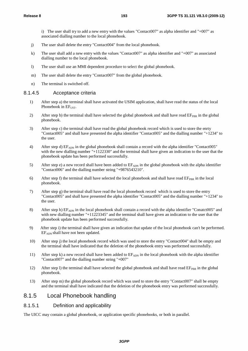
3GPP
Release 8 193 3GPP TS 31.121 V8.3.0 (2009-12)
i) The user shall try to add a new entry with the values "Contact007" as alpha identifier and "+007" as associated dialling number to the local phonebook.
j) The user shall delete the entry "Contact004" from the local phonebook.
k) The user shall add a new entry with the values "Contact007" as alpha identifier and "+007" as associated dialling number to the local phonebook.
l) The user shall use an MMI dependent procedure to select the global phonebook.
m) The user shall delete the entry "Contact007" from the global phonebook.
n) The terminal is switched off.
8.1.4.5 Acceptance criteria
1) After step a) the terminal shall have activated the USIM application, shall have read the status of the local Phonebook in EFUST.
2) After step b) the terminal shall have selected the global phonebook and shall have read EFPBR in the global phonebook.
3) After step c) the terminal shall have read the global phonebook record which is used to store the enrty "Contact005" and shall have presented the alpha identifier "Contact005" and the dialling number "+1234" to the user.
4) After step d) EFADN in the global phonebook shall contain a record with the alpha identifier "Contact005" with the new dialling number "+1122330" and the terminal shall have given an indication to the user that the phonebook update has been performed successfully.
5) After step e) a new record shall have been added to EFADN in the global phonebook with the alpha identifier "Contact006" and the dialling number string "+9876543210".
6) After step f) the terminal shall have selected the local phonebook and shall have read EFPBR in the local phonebook.
7) After step g) the terminal shall have read the local phonebook record which is used to store the entry "Contact005" and shall have presented the alpha identifier "Contact005" and the dialling number "+1234" to the user.
8) After step h) EFADN in the local phonebook shall contain a record with the alpha identifier "Conatct005" and with new dialling number "+11223345" and the terminal shall have given an indication to the user that the phonebook update has been performed successfully.
9) After step i) the terminal shall have given an indication that update of the local phonebook can't be performed. EFADN shall have not been updated.
10) After step j) the local phonebook record which was used to store the entry "Contact004" shall be empty and the terminal shall have indicated that the deletion of the phonebook entry was performed successfully.
11) After step k) a new record shall have been added to EFADN in the local phonebook with the alpha identifier "Contact007" and the dialling number string "+007"
12) After step l) the terminal shall have selected the global phonebook and shall have read EFPBR in the global phonebook.
13) After step m) the global phonebook record which was used to store the entry "Contact007" shall be empty and the terminal shall have indicated that the deletion of the phonebook entry was performed successfully.
8.1.5 Local Phonebook handling 8.1.5.1 Definition and applicability
The UICC may contain a global phonebook, or application specific phonebooks, or both in parallel.
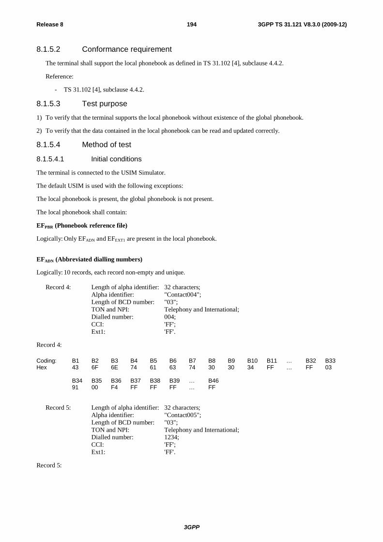
3GPP
Release 8 194 3GPP TS 31.121 V8.3.0 (2009-12)
8.1.5.2 Conformance requirement
The terminal shall support the local phonebook as defined in TS 31.102 [4], subclause 4.4.2.
Reference:
- TS 31.102 [4], subclause 4.4.2.
8.1.5.3 Test purpose
1) To verify that the terminal supports the local phonebook without existence of the global phonebook.
2) To verify that the data contained in the local phonebook can be read and updated correctly.
8.1.5.4 Method of test
8.1.5.4.1 Initial conditions
The terminal is connected to the USIM Simulator.
The default USIM is used with the following exceptions:
The local phonebook is present, the global phonebook is not present.
The local phonebook shall contain:
EFPBR (Phonebook reference file)
Logically: Only EFADN and EFEXT1 are present in the local phonebook.
EFADN (Abbreviated dialling numbers)
Logically: 10 records, each record non-empty and unique. Record 4: Length of alpha identifier: 32 characters; Alpha identifier: "Contact004"; Length of BCD number: "03"; TON and NPI: Telephony and International; Dialled number: 004; CCI: 'FF'; Ext1: 'FF'.
Record 4:
Coding: B1 B2 B3 B4 B5 B6 B7 B8 B9 B10 B11 … B32 B33 Hex 43 6F 6E 74 61 63 74 30 30 34 FF … FF 03 B34 B35 B36 B37 B38 B39 … B46 91 00 F4 FF FF FF … FF
Record 5: Length of alpha identifier: 32 characters; Alpha identifier: "Contact005"; Length of BCD number: "03"; TON and NPI: Telephony and International; Dialled number: 1234; CCI: 'FF'; Ext1: 'FF'.
Record 5:

3GPP
Release 8 195 3GPP TS 31.121 V8.3.0 (2009-12)
Coding: B1 B2 B3 B4 B5 B6 B7 B8 B9 B10 B11 … B32 B33 Hex 43 6F 6E 74 61 63 74 30 30 35 FF … FF 03 B34 B35 B36 B37 B38 B39 … B46 91 21 43 FF FF FF … FF
8.1.5.4.2 Procedure
a) The terminal is switched on and the USIM application shall be activated.
b) The user shall use an MMI dependent procedure to select the phonebook on the USIM (local phonebook).
c) The local phonebook record with the alpha identifier "Contact005" and the associated dialling number shall be read by the user.
d) The dialling number of the local phonebook record with the alpha identifier "Contact005" shall be set to "+11223345" and the alpha identifier shall be changed to "Contact8901234567890123456789012".
e) The user shall try to add a new entry with the values "Contact007" as alpha identifier and "+007" as associated dialling number to the local phonebook.
f) The user shall delete the entry "Contact004" from the local phonebook.
g) The user shall add a new entry with the values "Contact007" as alpha identifier and "+007" as associated dialling number to the local phonebook.
h) The terminal is switched off.
8.1.5.5 Acceptance criteria
1) After step a) the terminal shall have activated the USIM application, shall have read the status of the local Phonebook in EFUST.
2) After step b) the terminal shall have selected the local phonebook and shall have read EFPBR in the local phonebook.
3) After step c) the terminal shall have read the local phonebook record which is used to store the entry "Contact005" and shall have presented the alpha identifier "Contact005" and the dialling number "+1234" to the user.
4) After step d) EFADN in the local phonebook shall contain a record with the new alpha identifier "Contact8901234567890123456789012" and the dialling number "+11223345" and the terminal shall have given an indication to the user that the phonebook update has been performed successfully.
5) After step e) the terminal shall have given an indication that update of the local phonebook can't be performed. EFADN shall have not been updated.
6) After step f) the local phonebook record which was used to store the entry "Contact004" in the local phonebook shall be empty and the terminal shall have indicated that the deletion of the phonebook entry was performed successfully.
7) After step g) a new record shall have been added to EFADN in the local phonebook with the alpha identifier "Contact007" and the dialling number string "+007"
8.2 Short message handling report 8.2.1 Correct storage of a SM on the USIM
8.2.1.1 Definition and applicability
Once a SMS is received by the UE, the Terminal shall store the SM on the USIM, if this is indicated by the class 2 of the SMS (USIM specific SM). For this it is assumed, that at least one relevant SMS field are available on the USIM and
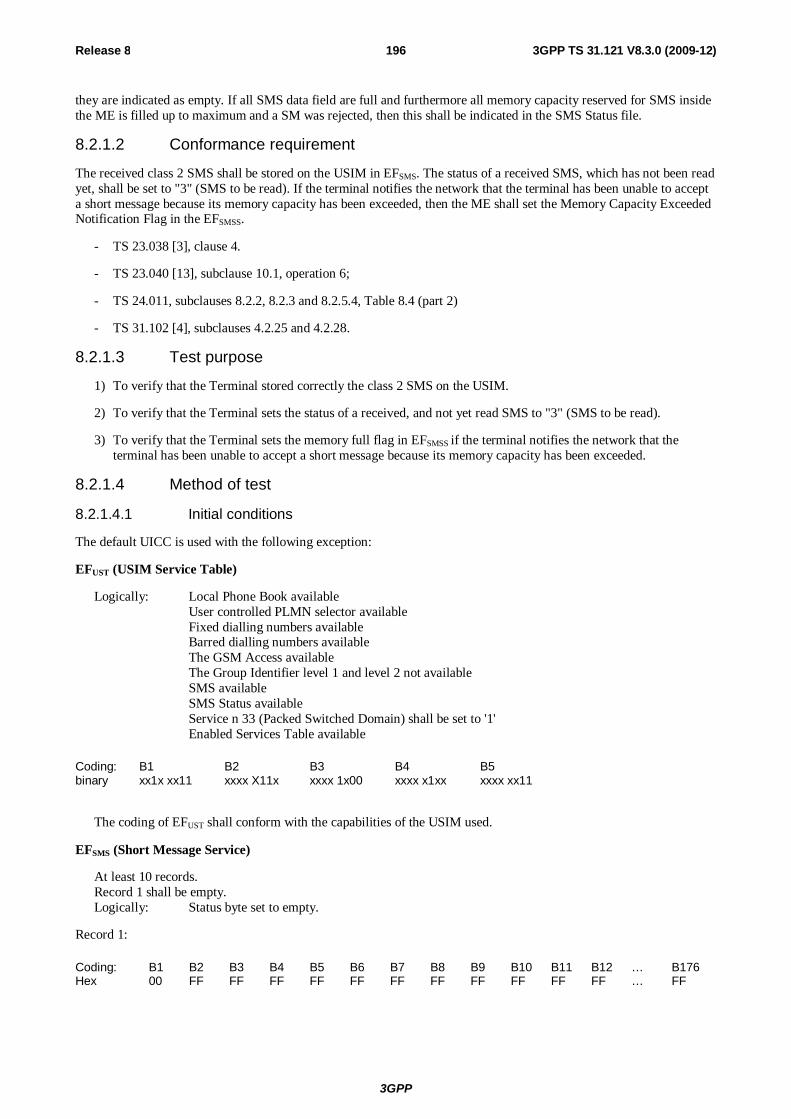
3GPP
Release 8 196 3GPP TS 31.121 V8.3.0 (2009-12)
they are indicated as empty. If all SMS data field are full and furthermore all memory capacity reserved for SMS inside the ME is filled up to maximum and a SM was rejected, then this shall be indicated in the SMS Status file.
8.2.1.2 Conformance requirement
The received class 2 SMS shall be stored on the USIM in EFSMS. The status of a received SMS, which has not been read yet, shall be set to "3" (SMS to be read). If the terminal notifies the network that the terminal has been unable to accept a short message because its memory capacity has been exceeded, then the ME shall set the Memory Capacity Exceeded Notification Flag in the EFSMSS.
- TS 23.038 [3], clause 4.
- TS 23.040 [13], subclause 10.1, operation 6;
- TS 24.011, subclauses 8.2.2, 8.2.3 and 8.2.5.4, Table 8.4 (part 2)
- TS 31.102 [4], subclauses 4.2.25 and 4.2.28.
8.2.1.3 Test purpose
1) To verify that the Terminal stored correctly the class 2 SMS on the USIM.
2) To verify that the Terminal sets the status of a received, and not yet read SMS to "3" (SMS to be read).
3) To verify that the Terminal sets the memory full flag in EFSMSS if the terminal notifies the network that the terminal has been unable to accept a short message because its memory capacity has been exceeded.
8.2.1.4 Method of test
8.2.1.4.1 Initial conditions
The default UICC is used with the following exception:
EFUST (USIM Service Table)
Logically: Local Phone Book available User controlled PLMN selector available Fixed dialling numbers available Barred dialling numbers available The GSM Access available The Group Identifier level 1 and level 2 not available SMS available SMS Status available Service n 33 (Packed Switched Domain) shall be set to '1'
Enabled Services Table available
Coding: B1 B2 B3 B4 B5 binary xx1x xx11 xxxx X11x xxxx 1x00 xxxx x1xx xxxx xx11
The coding of EFUST shall conform with the capabilities of the USIM used.
EFSMS (Short Message Service)
At least 10 records. Record 1 shall be empty. Logically: Status byte set to empty.
Record 1:
Coding: B1 B2 B3 B4 B5 B6 B7 B8 B9 B10 B11 B12 … B176 Hex 00 FF FF FF FF FF FF FF FF FF FF FF … FF
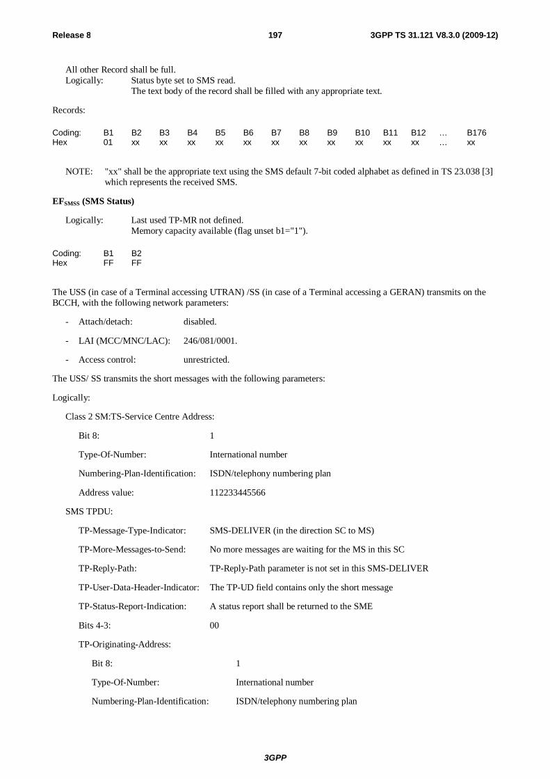
3GPP
Release 8 197 3GPP TS 31.121 V8.3.0 (2009-12)
All other Record shall be full. Logically: Status byte set to SMS read. The text body of the record shall be filled with any appropriate text.
Records:
Coding: B1 B2 B3 B4 B5 B6 B7 B8 B9 B10 B11 B12 … B176 Hex 01 xx xx xx xx xx xx xx xx xx xx xx … xx
NOTE: "xx" shall be the appropriate text using the SMS default 7-bit coded alphabet as defined in TS 23.038 [3] which represents the received SMS.
EFSMSS (SMS Status)
Logically: Last used TP-MR not defined. Memory capacity available (flag unset b1="1").
Coding: B1 B2 Hex FF FF
The USS (in case of a Terminal accessing UTRAN) /SS (in case of a Terminal accessing a GERAN) transmits on the BCCH, with the following network parameters:
- Attach/detach: disabled.
- LAI (MCC/MNC/LAC): 246/081/0001.
- Access control: unrestricted.
The USS/ SS transmits the short messages with the following parameters:
Logically:
Class 2 SM:TS-Service Centre Address:
Bit 8: 1
Type-Of-Number: International number
Numbering-Plan-Identification: ISDN/telephony numbering plan
Address value: 112233445566
SMS TPDU:
TP-Message-Type-Indicator: SMS-DELIVER (in the direction SC to MS)
TP-More-Messages-to-Send: No more messages are waiting for the MS in this SC
TP-Reply-Path: TP-Reply-Path parameter is not set in this SMS-DELIVER
TP-User-Data-Header-Indicator: The TP-UD field contains only the short message
TP-Status-Report-Indication: A status report shall be returned to the SME
Bits 4-3: 00
TP-Originating-Address:
Bit 8: 1
Type-Of-Number: International number
Numbering-Plan-Identification: ISDN/telephony numbering plan
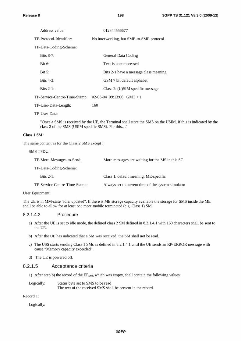
3GPP
Release 8 198 3GPP TS 31.121 V8.3.0 (2009-12)
Address value: 012344556677
TP-Protocol-Identifier: No interworking, but SME-to-SME protocol
TP-Data-Coding-Scheme:
Bits 8-7: General Data Coding
Bit 6: Text is uncompressed
Bit 5: Bits 2-1 have a message class meaning
Bits 4-3: GSM 7 bit default alphabet
Bits 2-1: Class 2: (U)SIM specific message
TP-Service-Centre-Time-Stamp: 02-03-04 09:13:06 GMT + 1
TP-User-Data-Length: 160
TP-User-Data:
"Once a SMS is received by the UE, the Terminal shall store the SMS on the USIM, if this is indicated by the class 2 of the SMS (USIM specific SMS). For this…"
Class 1 SM:
The same content as for the Class 2 SMS except :
SMS TPDU:
TP-More-Messages-to-Send: More messages are waiting for the MS in this SC
TP-Data-Coding-Scheme:
Bits 2-1: Class 1: default meaning: ME-specific
TP-Service-Centre-Time-Stamp: Always set to current time of the system simulator
User Equipment:
The UE is in MM-state "idle, updated". If there is ME storage capacity available the storage for SMS inside the ME shall be able to allow for at least one more mobile terminated (e.g. Class 1) SM.
8.2.1.4.2 Procedure
a) After the UE is set to idle mode, the defined class 2 SM defined in 8.2.1.4.1 with 160 characters shall be sent to the UE.
b) After the UE has indicated that a SM was received, the SM shall not be read.
c) The USS starts sending Class 1 SMs as defined in 8.2.1.4.1 until the UE sends an RP-ERROR message with cause “Memory capacity exceeded”.
d) The UE is powered off.
8.2.1.5 Acceptance criteria
1) After step b) the record of the EFSMS which was empty, shall contain the following values:
Logically: Status byte set to SMS to be read The text of the received SMS shall be present in the record.
Record 1:
Logically:
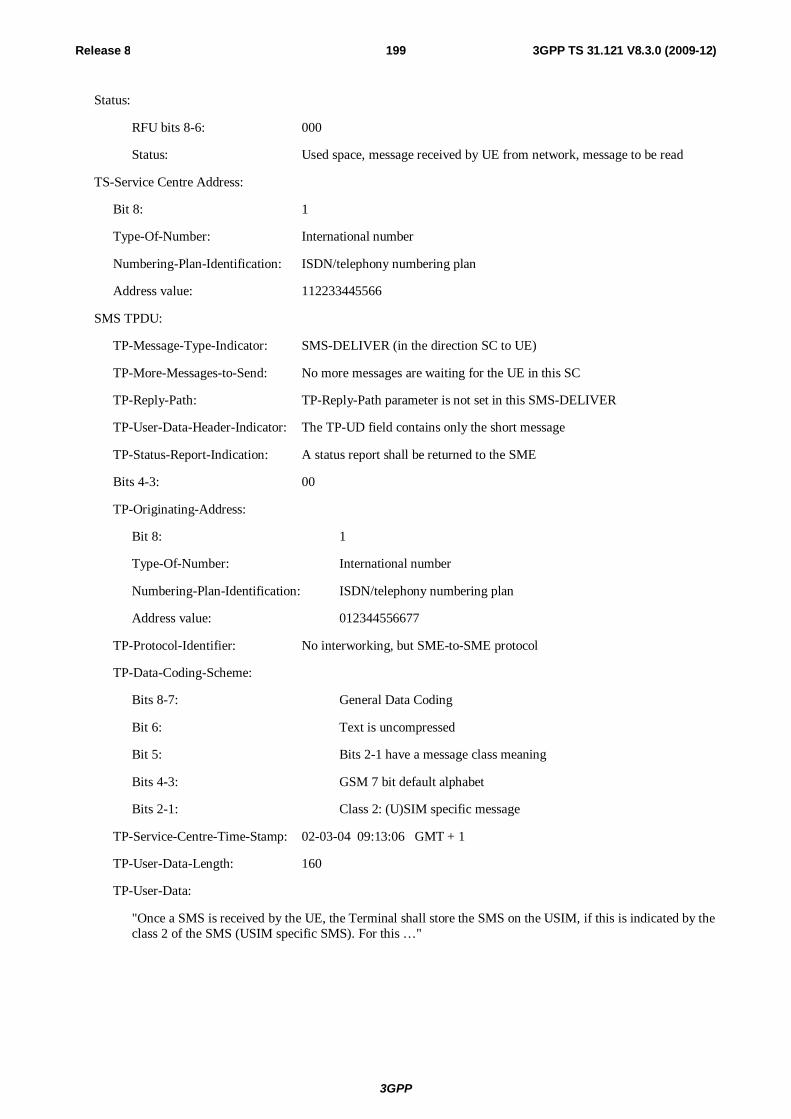
3GPP
Release 8 199 3GPP TS 31.121 V8.3.0 (2009-12)
Status:
RFU bits 8-6: 000
Status: Used space, message received by UE from network, message to be read
TS-Service Centre Address:
Bit 8: 1
Type-Of-Number: International number
Numbering-Plan-Identification: ISDN/telephony numbering plan
Address value: 112233445566
SMS TPDU:
TP-Message-Type-Indicator: SMS-DELIVER (in the direction SC to UE)
TP-More-Messages-to-Send: No more messages are waiting for the UE in this SC
TP-Reply-Path: TP-Reply-Path parameter is not set in this SMS-DELIVER
TP-User-Data-Header-Indicator: The TP-UD field contains only the short message
TP-Status-Report-Indication: A status report shall be returned to the SME
Bits 4-3: 00
TP-Originating-Address:
Bit 8: 1
Type-Of-Number: International number
Numbering-Plan-Identification: ISDN/telephony numbering plan
Address value: 012344556677
TP-Protocol-Identifier: No interworking, but SME-to-SME protocol
TP-Data-Coding-Scheme:
Bits 8-7: General Data Coding
Bit 6: Text is uncompressed
Bit 5: Bits 2-1 have a message class meaning
Bits 4-3: GSM 7 bit default alphabet
Bits 2-1: Class 2: (U)SIM specific message
TP-Service-Centre-Time-Stamp: 02-03-04 09:13:06 GMT + 1
TP-User-Data-Length: 160
TP-User-Data:
"Once a SMS is received by the UE, the Terminal shall store the SMS on the USIM, if this is indicated by the class 2 of the SMS (USIM specific SMS). For this …"
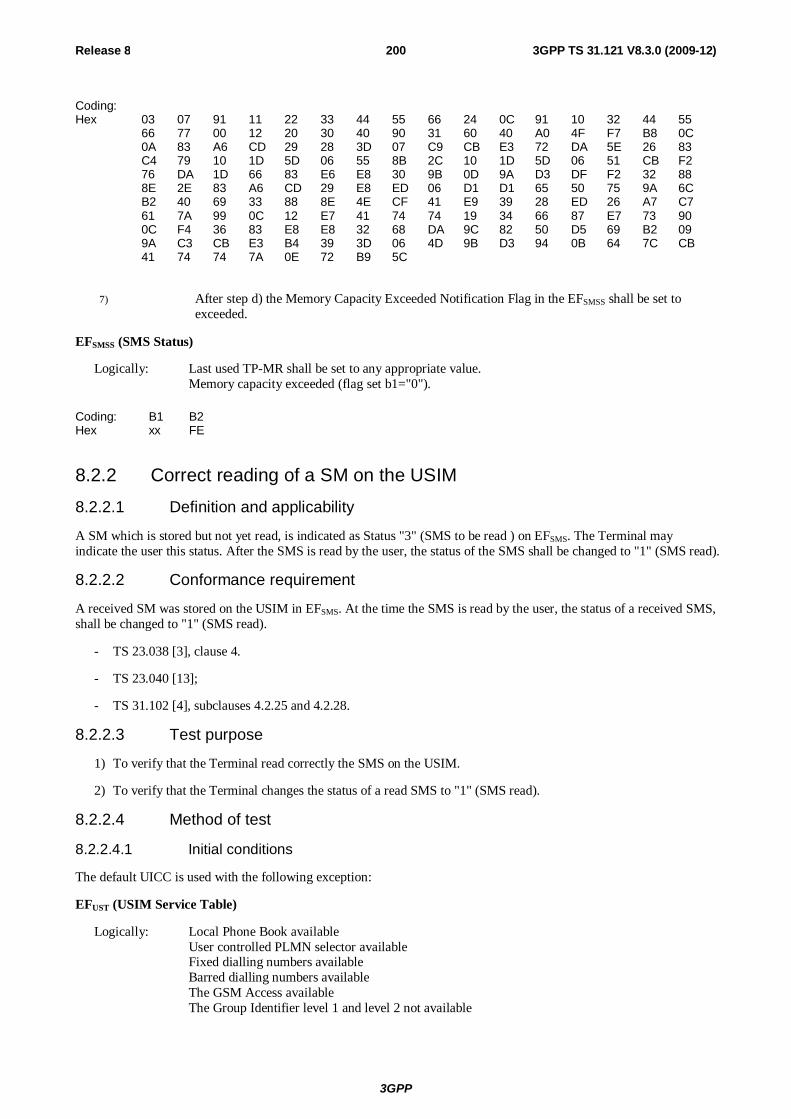
3GPP
Release 8 200 3GPP TS 31.121 V8.3.0 (2009-12)
Coding: Hex 03 07 91 11 22 33 44 55 66 24 0C 91 10 32 44 55 66 77 00 12 20 30 40 90 31 60 40 A0 4F F7 B8 0C 0A 83 A6 CD 29 28 3D 07 C9 CB E3 72 DA 5E 26 83 C4 79 10 1D 5D 06 55 8B 2C 10 1D 5D 06 51 CB F2 76 DA 1D 66 83 E6 E8 30 9B 0D 9A D3 DF F2 32 88 8E 2E 83 A6 CD 29 E8 ED 06 D1 D1 65 50 75 9A 6C B2 40 69 33 88 8E 4E CF 41 E9 39 28 ED 26 A7 C7 61 7A 99 0C 12 E7 41 74 74 19 34 66 87 E7 73 90 0C F4 36 83 E8 E8 32 68 DA 9C 82 50 D5 69 B2 09 9A C3 CB E3 B4 39 3D 06 4D 9B D3 94 0B 64 7C CB 41 74 74 7A 0E 72 B9 5C
7) After step d) the Memory Capacity Exceeded Notification Flag in the EFSMSS shall be set to exceeded.
EFSMSS (SMS Status)
Logically: Last used TP-MR shall be set to any appropriate value. Memory capacity exceeded (flag set b1="0").
Coding: B1 B2 Hex xx FE
8.2.2 Correct reading of a SM on the USIM
8.2.2.1 Definition and applicability
A SM which is stored but not yet read, is indicated as Status "3" (SMS to be read ) on EFSMS. The Terminal may indicate the user this status. After the SMS is read by the user, the status of the SMS shall be changed to "1" (SMS read).
8.2.2.2 Conformance requirement
A received SM was stored on the USIM in EFSMS. At the time the SMS is read by the user, the status of a received SMS, shall be changed to "1" (SMS read).
- TS 23.038 [3], clause 4.
- TS 23.040 [13];
- TS 31.102 [4], subclauses 4.2.25 and 4.2.28.
8.2.2.3 Test purpose
1) To verify that the Terminal read correctly the SMS on the USIM.
2) To verify that the Terminal changes the status of a read SMS to "1" (SMS read).
8.2.2.4 Method of test
8.2.2.4.1 Initial conditions
The default UICC is used with the following exception:
EFUST (USIM Service Table)
Logically: Local Phone Book available User controlled PLMN selector available Fixed dialling numbers available Barred dialling numbers available The GSM Access available The Group Identifier level 1 and level 2 not available
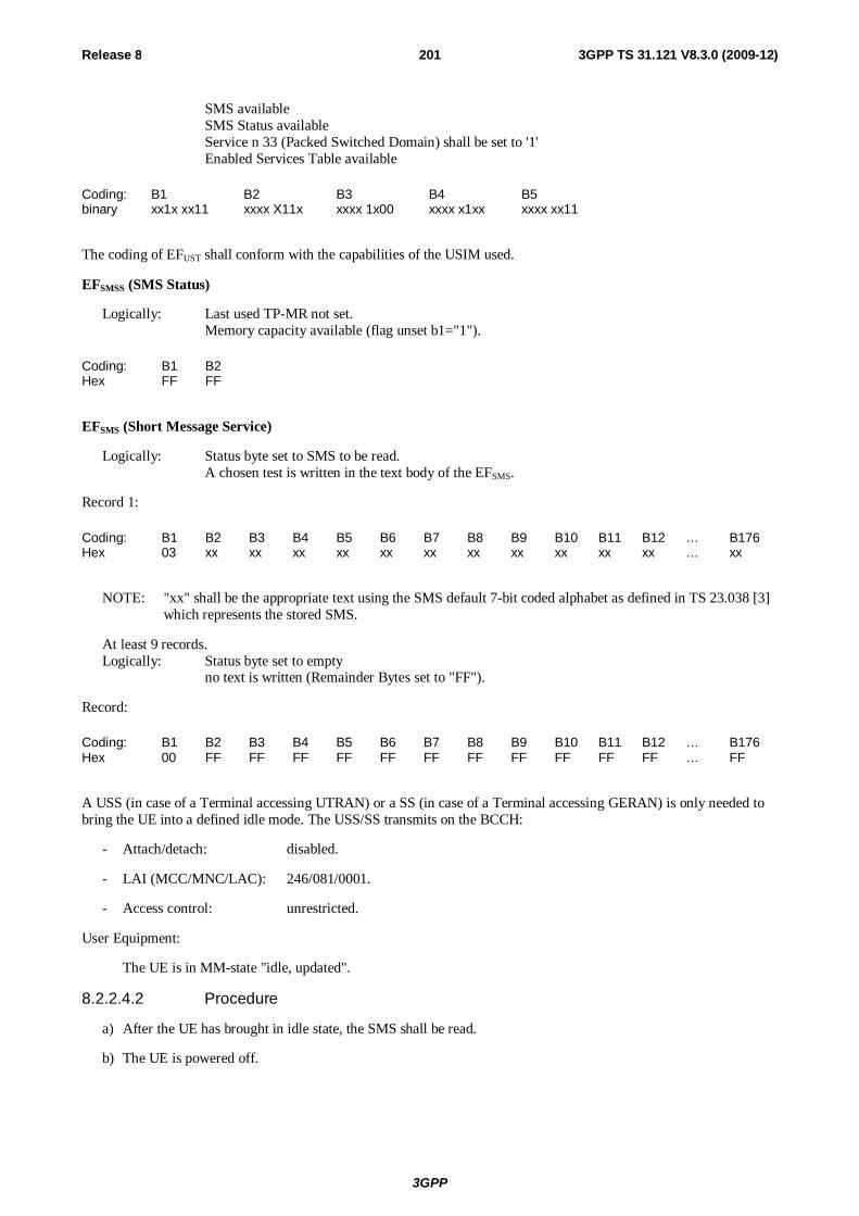
3GPP
Release 8 201 3GPP TS 31.121 V8.3.0 (2009-12)
SMS available SMS Status available Service n 33 (Packed Switched Domain) shall be set to '1'
Enabled Services Table available
Coding: B1 B2 B3 B4 B5 binary xx1x xx11 xxxx X11x xxxx 1x00 xxxx x1xx xxxx xx11
The coding of EFUST shall conform with the capabilities of the USIM used.
EFSMSS (SMS Status)
Logically: Last used TP-MR not set. Memory capacity available (flag unset b1="1").
Coding: B1 B2 Hex FF FF
EFSMS (Short Message Service)
Logically: Status byte set to SMS to be read. A chosen test is written in the text body of the EFSMS.
Record 1:
Coding: B1 B2 B3 B4 B5 B6 B7 B8 B9 B10 B11 B12 … B176 Hex 03 xx xx xx xx xx xx xx xx xx xx xx … xx
NOTE: "xx" shall be the appropriate text using the SMS default 7-bit coded alphabet as defined in TS 23.038 [3] which represents the stored SMS.
At least 9 records. Logically: Status byte set to empty no text is written (Remainder Bytes set to "FF").
Record:
Coding: B1 B2 B3 B4 B5 B6 B7 B8 B9 B10 B11 B12 … B176 Hex 00 FF FF FF FF FF FF FF FF FF FF FF … FF
A USS (in case of a Terminal accessing UTRAN) or a SS (in case of a Terminal accessing GERAN) is only needed to bring the UE into a defined idle mode. The USS/SS transmits on the BCCH:
- Attach/detach: disabled.
- LAI (MCC/MNC/LAC): 246/081/0001.
- Access control: unrestricted.
User Equipment:
The UE is in MM-state "idle, updated".
8.2.2.4.2 Procedure
a) After the UE has brought in idle state, the SMS shall be read.
b) The UE is powered off.
3GPP
Release 8 202 3GPP TS 31.121 V8.3.0 (2009-12)
8.2.2.5 Acceptance criteria
1) After a) the correct text of the SMS shall be read from the UE display.
2) After step b) the EFSMS record 1 shall contains the following values:
Logically: Status byte set to SMS read. The entire content of the SMS shall be unchanged.
Record 1:
Coding: B1 B2 B3 B4 B5 B6 B7 B8 B9 B10 B11 B12 … B176 Hex 01 xx xx Xx xx xx xx xx xx xx xx xx … xx
NOTE: "xx" shall be the appropriate text using the SMS default 7-bit coded alphabet as defined in TS 23.038 [3] which represents the stored SMS.
8.3 MMS related tests 8.3.1 UE recognising the priority order of MMS Issuer Connectivity
Parameters
8.3.1.1 Definition and applicability
An MMS User Agent shall use the MMS related information stored in the USIM, if present, unless otherwise specified by the user. Some of these sets of MMS connectivity parameters are preset by the issuer of the USIM with the first supported set being the default. This information is used to connect to the network for purpose of accessing the MMS Relay/Server.
The MMS connectivity information on the USIM includes preferences for the selection of Interface to Core Network and Bearer parameters. If these are stored on the USIM the MMS-capable UE shall automatically select the Interface to Core Network and Bearer parameters based on their order of precedence defined on the USIM unless otherwise specified by the user.
MMS user preferences information, which is stored on the USIM, shall be used by an MMS User Agent for user assistance in preparation of terminal-originated MMs (e.g. default values for parameters that are often used).
8.3.1.2 Conformance requirement
The Terminal's MMS User Agent shall use the MMS connectivity parameters stored first in the supported parameter sets of EFMMSICP as default parameters to connect to the network for MMS purposes (i.e. sending an User generated MM).
- TS 31.102 [4], subclauses 4.2.69 and 5.3.30;
- TS 23.140 [23], subclause 7.1.14 and Annex F.
MMS user preferences information, which is stored on the USIM, shall be used by an MMS User Agent for user assistance in preparation of terminal-originated MMs.
- TS 31.102 [4], subclauses 4.2.70 and 5.3.31;
- TS 23.140 [23], subclause 7.1.14 and Annex F.
8.3.1.3 Test purpose
1) To verify that the Terminal's MMS User Agent uses the MMS connectivity parameter stored on the USIM to connect to the network for MMS purposes.
2) To verify that the Terminal's MMS User Agent uses the first stored set of supported parameters in EFMMSICP as default.
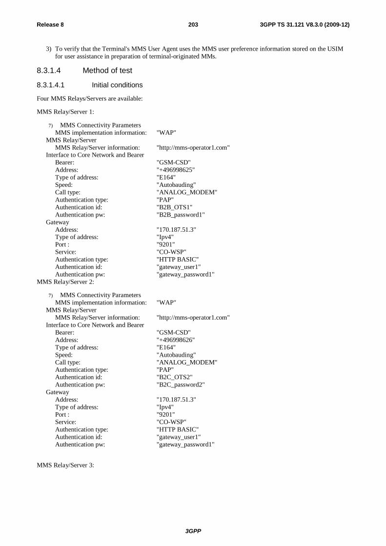
3GPP
Release 8 203 3GPP TS 31.121 V8.3.0 (2009-12)
3) To verify that the Terminal's MMS User Agent uses the MMS user preference information stored on the USIM for user assistance in preparation of terminal-originated MMs.
8.3.1.4 Method of test
8.3.1.4.1 Initial conditions
Four MMS Relays/Servers are available:
MMS Relay/Server 1:
7) MMS Connectivity Parameters MMS implementation information: "WAP"
MMS Relay/Server MMS Relay/Server information: "http://mms-operator1.com"
Interface to Core Network and Bearer Bearer: "GSM-CSD" Address: "+496998625" Type of address: "E164" Speed: "Autobauding" Call type: "ANALOG_MODEM" Authentication type: "PAP" Authentication id: "B2B_OTS1" Authentication pw: "B2B_password1"
Gateway Address: "170.187.51.3" Type of address: "Ipv4" Port : "9201" Service: "CO-WSP" Authentication type: "HTTP BASIC" Authentication id: "gateway_user1" Authentication pw: "gateway_password1"
MMS Relay/Server 2:
7) MMS Connectivity Parameters MMS implementation information: "WAP"
MMS Relay/Server MMS Relay/Server information: "http://mms-operator1.com"
Interface to Core Network and Bearer Bearer: "GSM-CSD" Address: "+496998626" Type of address: "E164" Speed: "Autobauding" Call type: "ANALOG_MODEM" Authentication type: "PAP" Authentication id: "B2C_OTS2" Authentication pw: "B2C_password2"
Gateway Address: "170.187.51.3" Type of address: "Ipv4" Port : "9201" Service: "CO-WSP" Authentication type: "HTTP BASIC" Authentication id: "gateway_user1" Authentication pw: "gateway_password1"
MMS Relay/Server 3:

3GPP
Release 8 204 3GPP TS 31.121 V8.3.0 (2009-12)
7) MMS Connectivity Parameters MMS implementation information: "WAP"
MMS Relay/Server MMS Relay/Server information: "http://mms-operator1.com"
Interface to Core Network and Bearer Bearer: "GSM-GPRS" Address: "wap.B2B-operator1.com" Type of address: "APN" Call type: "ANALOG_MODEM" Delivery of erroneous SDU: "No" Residual Bit Error Rate: "1*10-5" SDU-Error-Ratio: "1*10-6" Traffic-class: "Interactive class" Maximum bit rate for downlink: "8 kbps" Authentication type: "PAP" Authentication id: "B2B_OTS1" Authentication pw: "B2B_password1"
Gateway Address: "170.187.51.3" Type of address: "Ipv4" Port : "9201" Service: "CO-WSP" Authentication type: "HTTP BASIC" Authentication id: "gateway_user1" Authentication pw: "gateway_password1"
MMS Relay/Server 4:
7) MMS Connectivity Parameters MMS implementation information: "WAP"
MMS Relay/Server MMS Relay/Server information: "http://mms-operator1.com"
Interface to Core Network and Bearer Bearer: "GSM-GPRS" Address: "wap.B2C-operator1.com" Type of address: "APN" Call type: "ANALOG_MODEM" Delivery of erroneous SDU: "No" Residual Bit Error Rate: "1*10-5" SDU-Error-Ratio: "1*10-6" Traffic-class: "Interactive class" Maximum bit rate for downlink: "8 kbps" Authentication type: "PAP" Authentication id: "B2C_OTS2" Authentication pw: "B2C_password2"
Gateway Address: "170.187.51.3" Type of address: "Ipv4" Port : "9201" Service: "CO-WSP" Authentication type: "HTTP BASIC" Authentication id: "gateway_user1" Authentication pw: "gateway_password1"
The default UICC is used with the following exceptions:

3GPP
Release 8 205 3GPP TS 31.121 V8.3.0 (2009-12)
EFUST (USIM Service Table)
Logically: Local Phone Book available User controlled PLMN selector available Fixed dialling numbers available Barred dialling numbers available The GSM Access available The Group Identifier level 1 and level 2 not available SMS available SMS Status available Service no. 33 (Packed Switched Domain) shall be set to '1'
Service no. 52 Multimedia Messaging Service available Service no. 55 MMS User Connectivity Parameters not available
Coding: B1 B2 B3 B4 B5 B6 B7 Binary xx1x xx11 x11x xxxx xxxx 1x00 xxxx x1xx xxxx xxx1 xxxx xxxx x0xx 1xxx
EFMMSN
Logically: MMS Status: Free space MMS Implementation : "00" MMS Notification: "FF FF … FF" (251 bytes) Extension file record number: "FF"
Coding: B1 B2 B3 B4 B5 … B254 B255 00 00 00 FF FF FF FF
EFMMSICP
Logically: MMS Connectivity Parameters
MMS Implementation MMS Implementation Information : "WAP"
MMS Relay/Server MMS Relay/Server Address "http://mms-operator1.com"
1st Interface to Core Network and Bearer Bearer: "GSM-CSD" Address: "+496998625" Type of address: "E164" Speed: "Autobauding" Call type: "ANALOG_MODEM" Authentication type: "PAP" Authentication id: "B2B_OTS1" Authentication pw: "B2B_password1"
2nd Interface to Core Network and Bearer Bearer: "GSM-CSD" Address: "+496998626" Type of address: "E164" Speed: "Autobauding" Call type: "ANALOG_MODEM" Authentication type: "PAP" Authentication id: "B2C_OTS2" Authentication pw: "B2C_password2"
3rd Interface to Core Network and Bearer Bearer: "GSM-GPRS" Address: "wap.B2B-operator1.com" Type of address: "APN" Call type: "ANALOG_MODEM" Delivery of erroneous SDU: "No" Residual Bit Error Rate: "1*10-5"
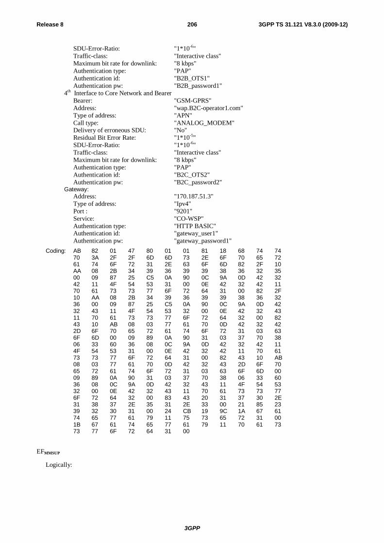
3GPP
Release 8 206 3GPP TS 31.121 V8.3.0 (2009-12)
SDU-Error-Ratio: "1*10-6" Traffic-class: "Interactive class" Maximum bit rate for downlink: "8 kbps" Authentication type: "PAP" Authentication id: "B2B_OTS1" Authentication pw: "B2B_password1"
4th Interface to Core Network and Bearer Bearer: "GSM-GPRS" Address: "wap.B2C-operator1.com" Type of address: "APN" Call type: "ANALOG_MODEM" Delivery of erroneous SDU: "No" Residual Bit Error Rate: "1*10-5" SDU-Error-Ratio: "1*10-6" Traffic-class: "Interactive class" Maximum bit rate for downlink: "8 kbps" Authentication type: "PAP" Authentication id: "B2C_OTS2" Authentication pw: "B2C_password2"
Gateway: Address: "170.187.51.3" Type of address: "Ipv4" Port : "9201" Service: "CO-WSP" Authentication type: "HTTP BASIC" Authentication id: "gateway_user1" Authentication pw: "gateway_password1"
Coding: AB 82 01 47 80 01 01 81 18 68 74 74 70 3A 2F 2F 6D 6D 73 2E 6F 70 65 72 61 74 6F 72 31 2E 63 6F 6D 82 2F 10 AA 08 2B 34 39 36 39 39 38 36 32 35 00 09 87 25 C5 0A 90 0C 9A 0D 42 32 42 11 4F 54 53 31 00 0E 42 32 42 11 70 61 73 73 77 6F 72 64 31 00 82 2F 10 AA 08 2B 34 39 36 39 39 38 36 32 36 00 09 87 25 C5 0A 90 0C 9A 0D 42 32 43 11 4F 54 53 32 00 0E 42 32 43 11 70 61 73 73 77 6F 72 64 32 00 82 43 10 AB 08 03 77 61 70 0D 42 32 42 2D 6F 70 65 72 61 74 6F 72 31 03 63 6F 6D 00 09 89 0A 90 31 03 37 70 38 06 33 60 36 08 0C 9A 0D 42 32 42 11 4F 54 53 31 00 0E 42 32 42 11 70 61 73 73 77 6F 72 64 31 00 82 43 10 AB 08 03 77 61 70 0D 42 32 43 2D 6F 70 65 72 61 74 6F 72 31 03 63 6F 6D 00 09 89 0A 90 31 03 37 70 38 06 33 60 36 08 0C 9A 0D 42 32 43 11 4F 54 53 32 00 0E 42 32 43 11 70 61 73 73 77 6F 72 64 32 00 83 43 20 31 37 30 2E 31 38 37 2E 35 31 2E 33 00 21 85 23 39 32 30 31 00 24 CB 19 9C 1A 67 61 74 65 77 61 79 11 75 73 65 72 31 00 1B 67 61 74 65 77 61 79 11 70 61 73 73 77 6F 72 64 31 00
EFMMSUP
Logically:
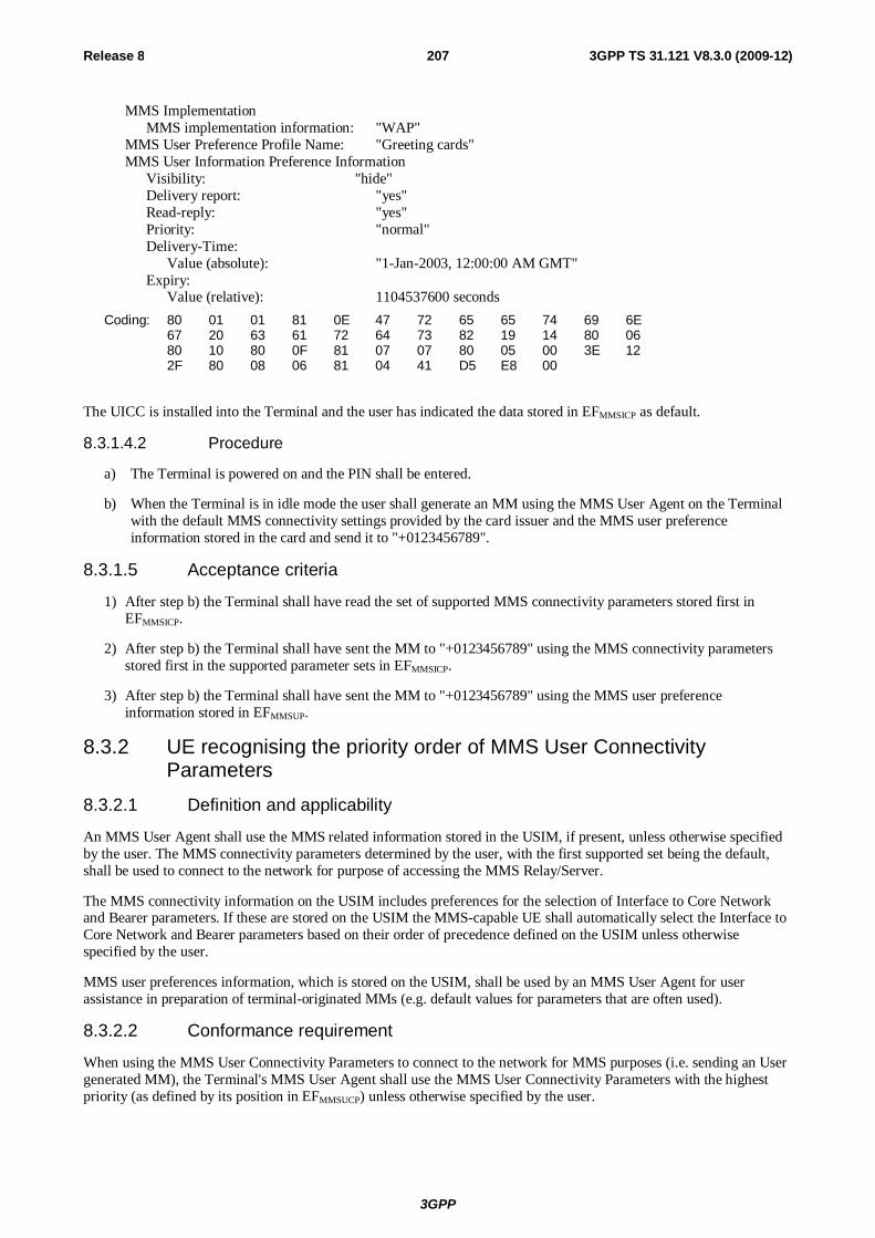
3GPP
Release 8 207 3GPP TS 31.121 V8.3.0 (2009-12)
MMS Implementation MMS implementation information: "WAP"
MMS User Preference Profile Name: "Greeting cards" MMS User Information Preference Information
Visibility: "hide" Delivery report: "yes" Read-reply: "yes" Priority: "normal" Delivery-Time:
Value (absolute): "1-Jan-2003, 12:00:00 AM GMT" Expiry:
Value (relative): 1104537600 seconds
Coding: 80 01 01 81 0E 47 72 65 65 74 69 6E 67 20 63 61 72 64 73 82 19 14 80 06 80 10 80 0F 81 07 07 80 05 00 3E 12 2F 80 08 06 81 04 41 D5 E8 00
The UICC is installed into the Terminal and the user has indicated the data stored in EFMMSICP as default.
8.3.1.4.2 Procedure
a) The Terminal is powered on and the PIN shall be entered.
b) When the Terminal is in idle mode the user shall generate an MM using the MMS User Agent on the Terminal with the default MMS connectivity settings provided by the card issuer and the MMS user preference information stored in the card and send it to "+0123456789".
8.3.1.5 Acceptance criteria
1) After step b) the Terminal shall have read the set of supported MMS connectivity parameters stored first in EFMMSICP.
2) After step b) the Terminal shall have sent the MM to "+0123456789" using the MMS connectivity parameters stored first in the supported parameter sets in EFMMSICP.
3) After step b) the Terminal shall have sent the MM to "+0123456789" using the MMS user preference information stored in EFMMSUP.
8.3.2 UE recognising the priority order of MMS User Connectivity Parameters
8.3.2.1 Definition and applicability
An MMS User Agent shall use the MMS related information stored in the USIM, if present, unless otherwise specified by the user. The MMS connectivity parameters determined by the user, with the first supported set being the default, shall be used to connect to the network for purpose of accessing the MMS Relay/Server.
The MMS connectivity information on the USIM includes preferences for the selection of Interface to Core Network and Bearer parameters. If these are stored on the USIM the MMS-capable UE shall automatically select the Interface to Core Network and Bearer parameters based on their order of precedence defined on the USIM unless otherwise specified by the user.
MMS user preferences information, which is stored on the USIM, shall be used by an MMS User Agent for user assistance in preparation of terminal-originated MMs (e.g. default values for parameters that are often used).
8.3.2.2 Conformance requirement
When using the MMS User Connectivity Parameters to connect to the network for MMS purposes (i.e. sending an User generated MM), the Terminal's MMS User Agent shall use the MMS User Connectivity Parameters with the highest priority (as defined by its position in EFMMSUCP) unless otherwise specified by the user.
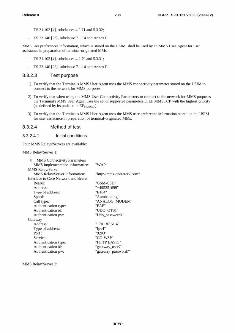
3GPP
Release 8 208 3GPP TS 31.121 V8.3.0 (2009-12)
- TS 31.102 [4], subclauses 4.2.71 and 5.3.32;
- TS 23.140 [23], subclause 7.1.14 and Annex F.
MMS user preferences information, which is stored on the USIM, shall be used by an MMS User Agent for user assistance in preparation of terminal-originated MMs.
- TS 31.102 [4], subclauses 4.2.70 and 5.3.31;
- TS 23.140 [23], subclause 7.1.14 and Annex F.
8.3.2.3 Test purpose
1) To verify that the Terminal's MMS User Agent uses the MMS connectivity parameter stored on the USIM to connect to the network for MMS purposes.
2) To verify that when using the MMS User Connectivity Parameters to connect to the network for MMS purposes the Terminal's MMS User Agent uses the set of supported parameters in EF MMSUCP with the highest priority (as defined by its position in EFMMSUCP).
3) To verify that the Terminal's MMS User Agent uses the MMS user preference information stored on the USIM for user assistance in preparation of terminal-originated MMs.
8.3.2.4 Method of test
8.3.2.4.1 Initial conditions
Four MMS Relays/Servers are available:
MMS Relay/Server 1:
7) MMS Connectivity Parameters MMS implementation information: "WAP"
MMS Relay/Server MMS Relay/Server information: "http://mms-operator2.com"
Interface to Core Network and Bearer Bearer: "GSM-CSD" Address: "+495251699" Type of address: "E164" Speed: "Autobauding" Call type: "ANALOG_MODEM" Authentication type: "PAP" Authentication id: "UDO_OTS1" Authentication pw: "Udo_password1"
Gateway Address: "170.187.51.4" Type of address: "Ipv4" Port : "9203" Service: "CO-WSP" Authentication type: "HTTP BASIC" Authentication id: "gateway_user7" Authentication pw: "gateway_password7"
MMS Relay/Server 2:

3GPP
Release 8 209 3GPP TS 31.121 V8.3.0 (2009-12)
7) MMS Connectivity Parameters MMS implementation information: "WAP"
MMS Relay/Server MMS Relay/Server information: "http://mms-operator2.com"
Interface to Core Network and Bearer Bearer: "GSM-CSD" Address: "+495251700" Type of address: "E164" Speed: "Autobauding" Call type: "ANALOG_MODEM" Authentication type: "PAP" Authentication id: "UDO_OTS2" Authentication pw: "Udo_password2"
Gateway Address: "170.187.51.4" Type of address: "Ipv4" Port : "9203" Service: "CO-WSP" Authentication type: "HTTP BASIC" Authentication id: "gateway_user7" Authentication pw: "gateway_password7"
MMS Relay/Server 3:
7) MMS Connectivity Parameters MMS implementation information: "WAP"
MMS Relay/Server MMS Relay/Server information: "http://mms-operator2.com"
Interface to Core Network and Bearer Bearer: "GSM-GPRS" Address: "wap.B2B-operator2.com" Type of address: "APN" Call type: "ANALOG_MODEM" Delivery of erroneous SDU: "No" Residual Bit Error Rate: "1*10-5" SDU-Error-Ratio: "1*10-6" Traffic-class: "Interactive class" Maximum bit rate for downlink: "8 kbps" Authentication type: "PAP" Authentication id: "UDO_OTS1" Authentication pw: "Udo_password1"
Gateway Address: "170.187.51.4" Type of address: "Ipv4" Port : "9203" Service: "CO-WSP" Authentication type: "HTTP BASIC" Authentication id: "gateway_user7" Authentication pw: "gateway_password7"
MMS Relay/Server 4:
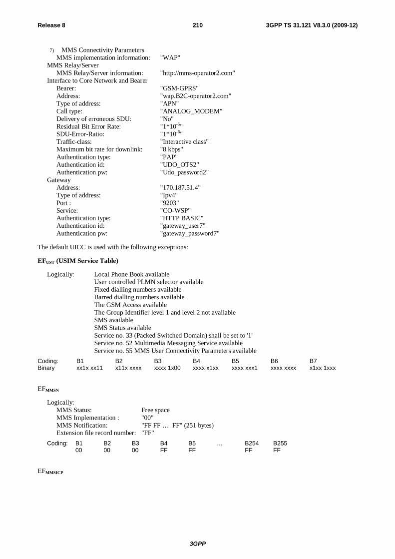
3GPP
Release 8 210 3GPP TS 31.121 V8.3.0 (2009-12)
7) MMS Connectivity Parameters MMS implementation information: "WAP"
MMS Relay/Server MMS Relay/Server information: "http://mms-operator2.com"
Interface to Core Network and Bearer Bearer: "GSM-GPRS" Address: "wap.B2C-operator2.com" Type of address: "APN" Call type: "ANALOG_MODEM" Delivery of erroneous SDU: "No" Residual Bit Error Rate: "1*10-5" SDU-Error-Ratio: "1*10-6" Traffic-class: "Interactive class" Maximum bit rate for downlink: "8 kbps" Authentication type: "PAP" Authentication id: "UDO_OTS2" Authentication pw: "Udo_password2"
Gateway Address: "170.187.51.4" Type of address: "Ipv4" Port : "9203" Service: "CO-WSP" Authentication type: "HTTP BASIC" Authentication id: "gateway_user7" Authentication pw: "gateway_password7"
The default UICC is used with the following exceptions:
EFUST (USIM Service Table)
Logically: Local Phone Book available User controlled PLMN selector available Fixed dialling numbers available Barred dialling numbers available The GSM Access available The Group Identifier level 1 and level 2 not available SMS available SMS Status available Service no. 33 (Packed Switched Domain) shall be set to '1'
Service no. 52 Multimedia Messaging Service available Service no. 55 MMS User Connectivity Parameters available
Coding: B1 B2 B3 B4 B5 B6 B7 Binary xx1x xx11 x11x xxxx xxxx 1x00 xxxx x1xx xxxx xxx1 xxxx xxxx x1xx 1xxx
EFMMSN
Logically: MMS Status: Free space MMS Implementation : "00" MMS Notification: "FF FF … FF" (251 bytes) Extension file record number: "FF"
Coding: B1 B2 B3 B4 B5 … B254 B255 00 00 00 FF FF FF FF
EFMMSICP
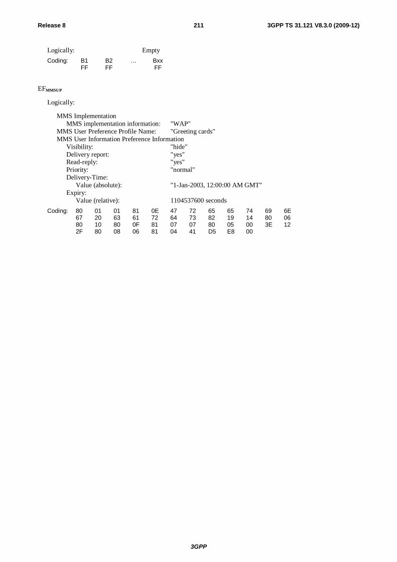
3GPP
Release 8 211 3GPP TS 31.121 V8.3.0 (2009-12)
Logically: Empty
Coding: B1 B2 … Bxx FF FF FF
EFMMSUP
Logically:
MMS Implementation MMS implementation information: "WAP"
MMS User Preference Profile Name: "Greeting cards" MMS User Information Preference Information
Visibility: "hide" Delivery report: "yes" Read-reply: "yes" Priority: "normal" Delivery-Time:
Value (absolute): "1-Jan-2003, 12:00:00 AM GMT" Expiry:
Value (relative): 1104537600 seconds
Coding: 80 01 01 81 0E 47 72 65 65 74 69 6E 67 20 63 61 72 64 73 82 19 14 80 06 80 10 80 0F 81 07 07 80 05 00 3E 12 2F 80 08 06 81 04 41 D5 E8 00
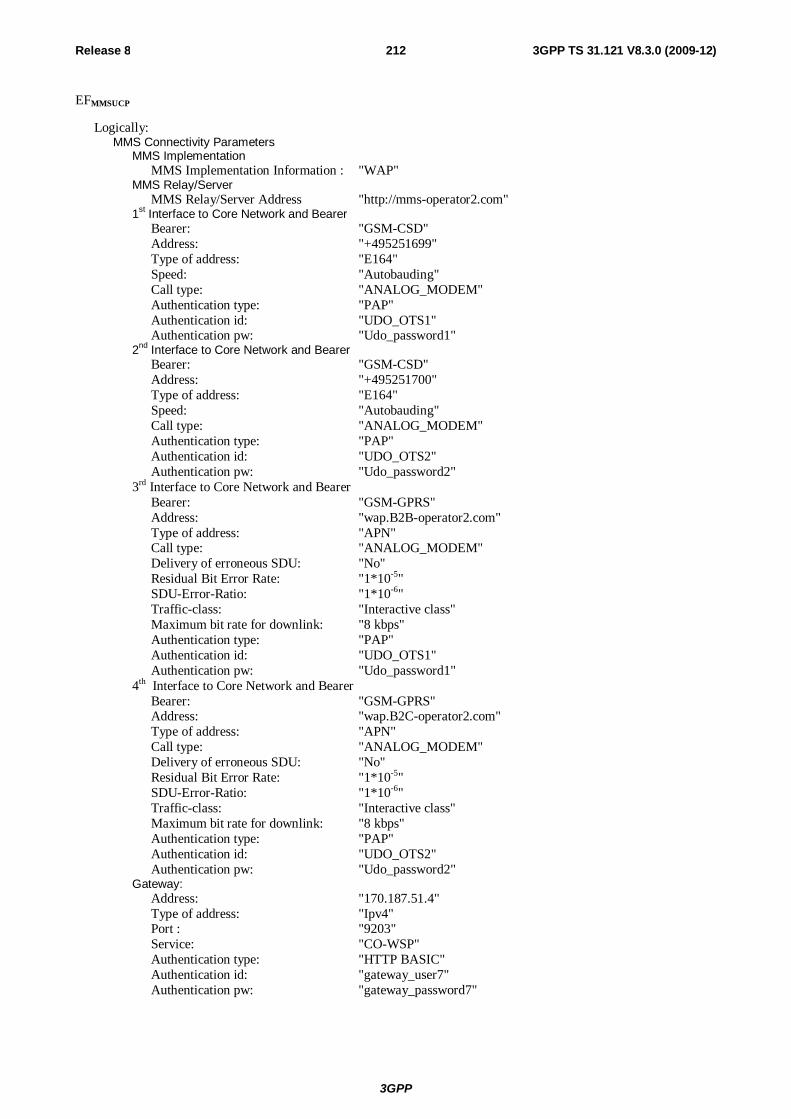
3GPP
Release 8 212 3GPP TS 31.121 V8.3.0 (2009-12)
EFMMSUCP
Logically: MMS Connectivity Parameters
MMS Implementation MMS Implementation Information : "WAP"
MMS Relay/Server MMS Relay/Server Address "http://mms-operator2.com"
1st Interface to Core Network and Bearer Bearer: "GSM-CSD" Address: "+495251699" Type of address: "E164" Speed: "Autobauding" Call type: "ANALOG_MODEM" Authentication type: "PAP" Authentication id: "UDO_OTS1" Authentication pw: "Udo_password1"
2nd Interface to Core Network and Bearer Bearer: "GSM-CSD" Address: "+495251700" Type of address: "E164" Speed: "Autobauding" Call type: "ANALOG_MODEM" Authentication type: "PAP" Authentication id: "UDO_OTS2" Authentication pw: "Udo_password2"
3rd Interface to Core Network and Bearer Bearer: "GSM-GPRS" Address: "wap.B2B-operator2.com" Type of address: "APN" Call type: "ANALOG_MODEM" Delivery of erroneous SDU: "No" Residual Bit Error Rate: "1*10-5" SDU-Error-Ratio: "1*10-6" Traffic-class: "Interactive class" Maximum bit rate for downlink: "8 kbps" Authentication type: "PAP" Authentication id: "UDO_OTS1" Authentication pw: "Udo_password1"
4th Interface to Core Network and Bearer Bearer: "GSM-GPRS" Address: "wap.B2C-operator2.com" Type of address: "APN" Call type: "ANALOG_MODEM" Delivery of erroneous SDU: "No" Residual Bit Error Rate: "1*10-5" SDU-Error-Ratio: "1*10-6" Traffic-class: "Interactive class" Maximum bit rate for downlink: "8 kbps" Authentication type: "PAP" Authentication id: "UDO_OTS2" Authentication pw: "Udo_password2"
Gateway: Address: "170.187.51.4" Type of address: "Ipv4" Port : "9203" Service: "CO-WSP" Authentication type: "HTTP BASIC" Authentication id: "gateway_user7" Authentication pw: "gateway_password7"
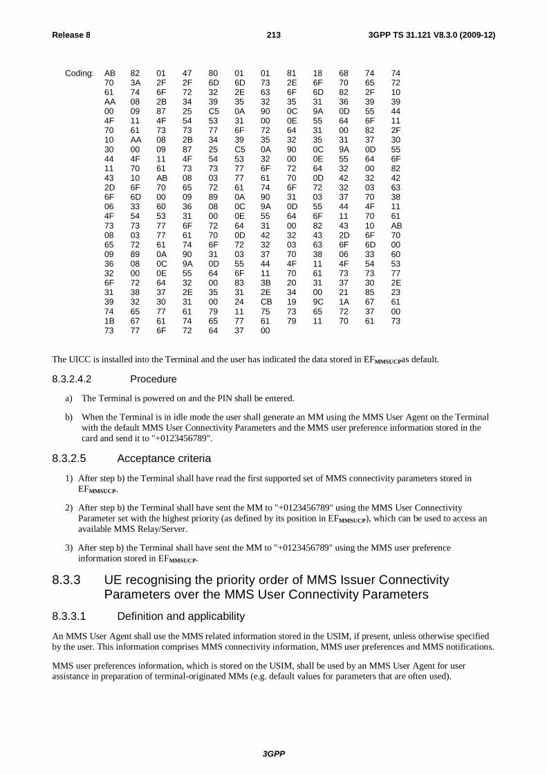
3GPP
Release 8 213 3GPP TS 31.121 V8.3.0 (2009-12)
Coding: AB 82 01 47 80 01 01 81 18 68 74 74 70 3A 2F 2F 6D 6D 73 2E 6F 70 65 72 61 74 6F 72 32 2E 63 6F 6D 82 2F 10 AA 08 2B 34 39 35 32 35 31 36 39 39 00 09 87 25 C5 0A 90 0C 9A 0D 55 44 4F 11 4F 54 53 31 00 0E 55 64 6F 11 70 61 73 73 77 6F 72 64 31 00 82 2F 10 AA 08 2B 34 39 35 32 35 31 37 30 30 00 09 87 25 C5 0A 90 0C 9A 0D 55 44 4F 11 4F 54 53 32 00 0E 55 64 6F 11 70 61 73 73 77 6F 72 64 32 00 82 43 10 AB 08 03 77 61 70 0D 42 32 42 2D 6F 70 65 72 61 74 6F 72 32 03 63 6F 6D 00 09 89 0A 90 31 03 37 70 38 06 33 60 36 08 0C 9A 0D 55 44 4F 11 4F 54 53 31 00 0E 55 64 6F 11 70 61 73 73 77 6F 72 64 31 00 82 43 10 AB 08 03 77 61 70 0D 42 32 43 2D 6F 70 65 72 61 74 6F 72 32 03 63 6F 6D 00 09 89 0A 90 31 03 37 70 38 06 33 60 36 08 0C 9A 0D 55 44 4F 11 4F 54 53 32 00 0E 55 64 6F 11 70 61 73 73 77 6F 72 64 32 00 83 3B 20 31 37 30 2E 31 38 37 2E 35 31 2E 34 00 21 85 23 39 32 30 31 00 24 CB 19 9C 1A 67 61 74 65 77 61 79 11 75 73 65 72 37 00 1B 67 61 74 65 77 61 79 11 70 61 73 73 77 6F 72 64 37 00
The UICC is installed into the Terminal and the user has indicated the data stored in EFMMSUCPas default.
8.3.2.4.2 Procedure
a) The Terminal is powered on and the PIN shall be entered.
b) When the Terminal is in idle mode the user shall generate an MM using the MMS User Agent on the Terminal with the default MMS User Connectivity Parameters and the MMS user preference information stored in the card and send it to "+0123456789".
8.3.2.5 Acceptance criteria
1) After step b) the Terminal shall have read the first supported set of MMS connectivity parameters stored in EFMMSUCP.
2) After step b) the Terminal shall have sent the MM to "+0123456789" using the MMS User Connectivity Parameter set with the highest priority (as defined by its position in EFMMSUCP), which can be used to access an available MMS Relay/Server.
3) After step b) the Terminal shall have sent the MM to "+0123456789" using the MMS user preference information stored in EFMMSUCP.
8.3.3 UE recognising the priority order of MMS Issuer Connectivity Parameters over the MMS User Connectivity Parameters
8.3.3.1 Definition and applicability
An MMS User Agent shall use the MMS related information stored in the USIM, if present, unless otherwise specified by the user. This information comprises MMS connectivity information, MMS user preferences and MMS notifications.
MMS user preferences information, which is stored on the USIM, shall be used by an MMS User Agent for user assistance in preparation of terminal-originated MMs (e.g. default values for parameters that are often used).
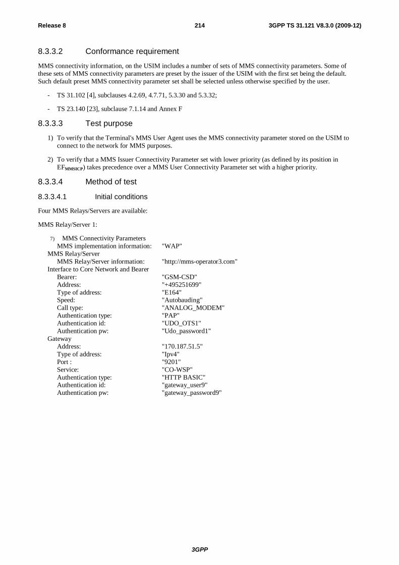
3GPP
Release 8 214 3GPP TS 31.121 V8.3.0 (2009-12)
8.3.3.2 Conformance requirement
MMS connectivity information, on the USIM includes a number of sets of MMS connectivity parameters. Some of these sets of MMS connectivity parameters are preset by the issuer of the USIM with the first set being the default. Such default preset MMS connectivity parameter set shall be selected unless otherwise specified by the user.
- TS 31.102 [4], subclauses 4.2.69, 4.7.71, 5.3.30 and 5.3.32;
- TS 23.140 [23], subclause 7.1.14 and Annex F
8.3.3.3 Test purpose
1) To verify that the Terminal's MMS User Agent uses the MMS connectivity parameter stored on the USIM to connect to the network for MMS purposes.
2) To verify that a MMS Issuer Connectivity Parameter set with lower priority (as defined by its position in EFMMSICP) takes precedence over a MMS User Connectivity Parameter set with a higher priority.
8.3.3.4 Method of test
8.3.3.4.1 Initial conditions
Four MMS Relays/Servers are available:
MMS Relay/Server 1:
7) MMS Connectivity Parameters MMS implementation information: "WAP"
MMS Relay/Server MMS Relay/Server information: "http://mms-operator3.com"
Interface to Core Network and Bearer Bearer: "GSM-CSD" Address: "+495251699" Type of address: "E164" Speed: "Autobauding" Call type: "ANALOG_MODEM" Authentication type: "PAP" Authentication id: "UDO_OTS1" Authentication pw: "Udo_password1"
Gateway Address: "170.187.51.5" Type of address: "Ipv4" Port : "9201" Service: "CO-WSP" Authentication type: "HTTP BASIC" Authentication id: "gateway_user9" Authentication pw: "gateway_password9"
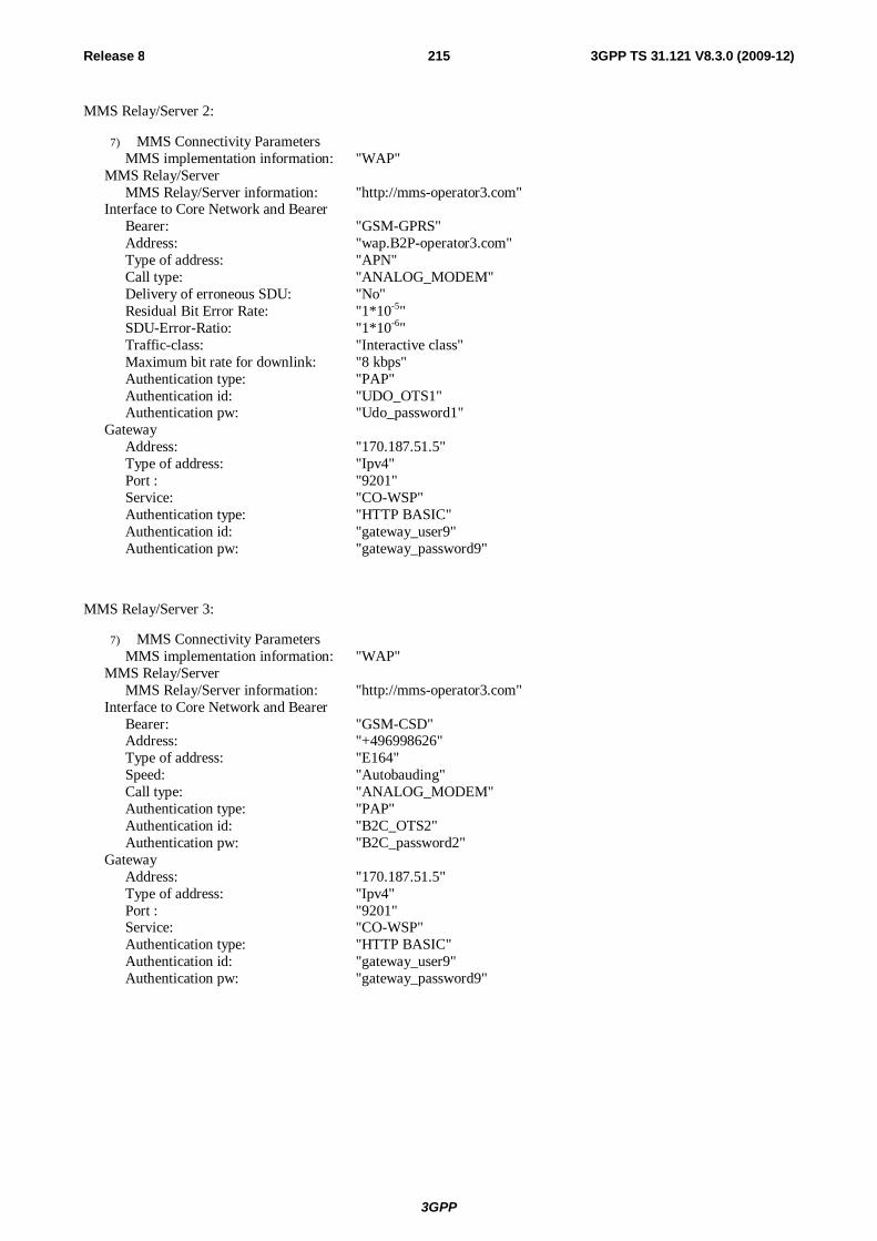
3GPP
Release 8 215 3GPP TS 31.121 V8.3.0 (2009-12)
MMS Relay/Server 2:
7) MMS Connectivity Parameters MMS implementation information: "WAP"
MMS Relay/Server MMS Relay/Server information: "http://mms-operator3.com"
Interface to Core Network and Bearer Bearer: "GSM-GPRS" Address: "wap.B2P-operator3.com" Type of address: "APN" Call type: "ANALOG_MODEM" Delivery of erroneous SDU: "No" Residual Bit Error Rate: "1*10-5" SDU-Error-Ratio: "1*10-6" Traffic-class: "Interactive class" Maximum bit rate for downlink: "8 kbps" Authentication type: "PAP" Authentication id: "UDO_OTS1" Authentication pw: "Udo_password1"
Gateway Address: "170.187.51.5" Type of address: "Ipv4" Port : "9201" Service: "CO-WSP" Authentication type: "HTTP BASIC" Authentication id: "gateway_user9" Authentication pw: "gateway_password9"
MMS Relay/Server 3:
7) MMS Connectivity Parameters MMS implementation information: "WAP"
MMS Relay/Server MMS Relay/Server information: "http://mms-operator3.com"
Interface to Core Network and Bearer Bearer: "GSM-CSD" Address: "+496998626" Type of address: "E164" Speed: "Autobauding" Call type: "ANALOG_MODEM" Authentication type: "PAP" Authentication id: "B2C_OTS2" Authentication pw: "B2C_password2"
Gateway Address: "170.187.51.5" Type of address: "Ipv4" Port : "9201" Service: "CO-WSP" Authentication type: "HTTP BASIC" Authentication id: "gateway_user9" Authentication pw: "gateway_password9"

3GPP
Release 8 216 3GPP TS 31.121 V8.3.0 (2009-12)
MMS Relay/Server 4:
7) MMS Connectivity Parameters MMS implementation information: "WAP"
MMS Relay/Server MMS Relay/Server information: "http://mms-operator3.com"
Interface to Core Network and Bearer Bearer: "GSM-GPRS" Address: "wap.B2C-operator3.com" Type of address: "APN" Call type: "ANALOG_MODEM" Delivery of erroneous SDU: "No" Residual Bit Error Rate: "1*10-5" SDU-Error-Ratio: "1*10-6" Traffic-class: "Interactive class" Maximum bit rate for downlink: "8 kbps" Authentication type: "PAP" Authentication id: "B2C_OTS2" Authentication pw: "B2C_password2"
Gateway Address: "170.187.51.5" Type of address: "Ipv4" Port : "9201" Service: "CO-WSP" Authentication type: "HTTP BASIC" Authentication id: "gateway_user9" Authentication pw: "gateway_password9"
The default UICC is used with the following exceptions:
EFUST (USIM Service Table)
Logically: Local Phone Book available User controlled PLMN selector available Fixed dialling numbers available Barred dialling numbers available The GSM Access available The Group Identifier level 1 and level 2 not available SMS available SMS Status available Service no. 33 (Packed Switched Domain) shall be set to '1'
Service no. 52 Multimedia Messaging Service available Service no. 55 MMS User Connectivity Parameters available
Coding: B1 B2 B3 B4 B5 B6 B7 Binary xx1x xx11 x11x xxxx xxxx 1x00 xxxx x1xx xxxx xxx1 xxxx xxxx x1xx 1xxx
EFMMSN
Logically: MMS Status: Free space MMS Implementation : "00" MMS Notification: "FF FF … FF" (251 bytes) Extension file record number: "FF"
Coding: B1 B2 B3 B4 B5 … B254 B255 00 00 00 FF FF FF FF
EFMMSICP
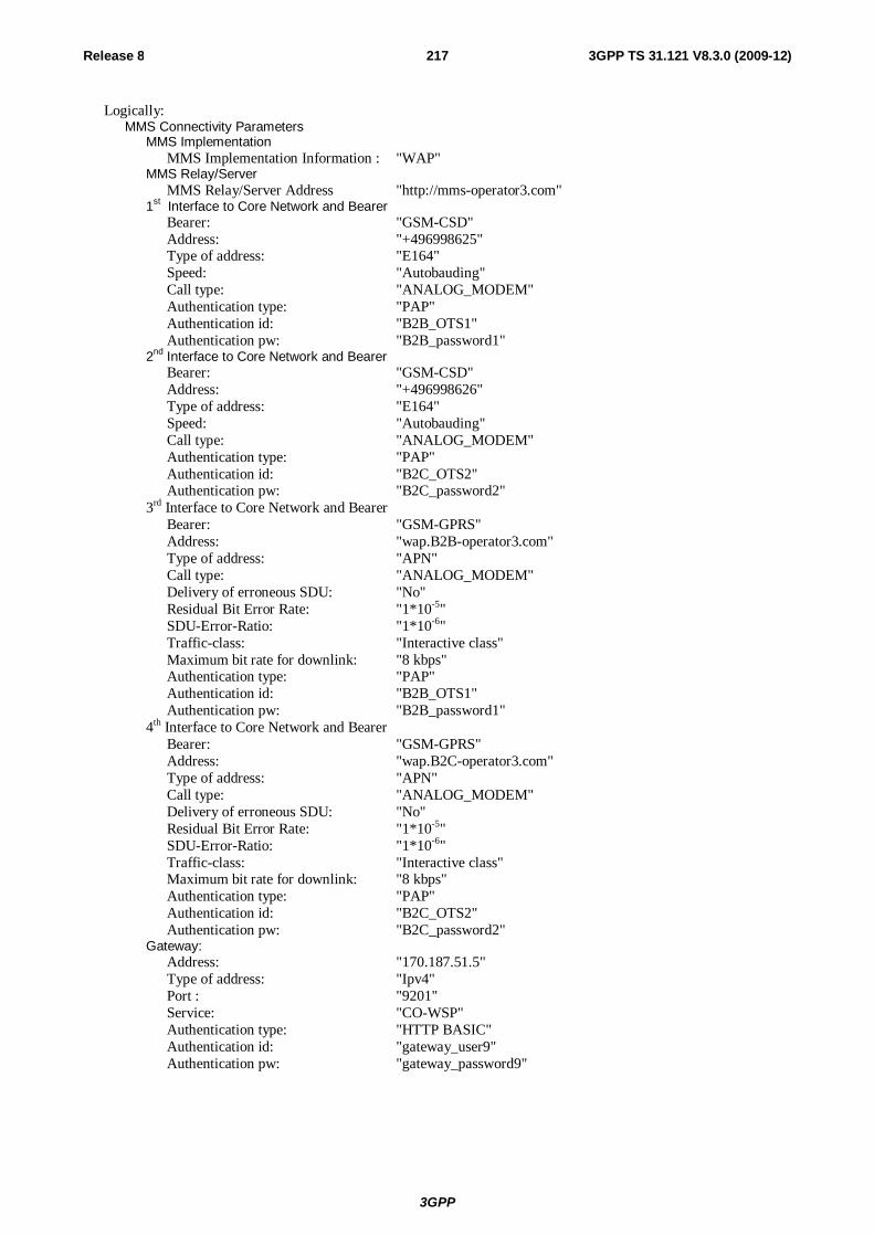
3GPP
Release 8 217 3GPP TS 31.121 V8.3.0 (2009-12)
Logically: MMS Connectivity Parameters
MMS Implementation MMS Implementation Information : "WAP"
MMS Relay/Server MMS Relay/Server Address "http://mms-operator3.com"
1st Interface to Core Network and Bearer Bearer: "GSM-CSD" Address: "+496998625" Type of address: "E164" Speed: "Autobauding" Call type: "ANALOG_MODEM" Authentication type: "PAP" Authentication id: "B2B_OTS1" Authentication pw: "B2B_password1"
2nd Interface to Core Network and Bearer Bearer: "GSM-CSD" Address: "+496998626" Type of address: "E164" Speed: "Autobauding" Call type: "ANALOG_MODEM" Authentication type: "PAP" Authentication id: "B2C_OTS2" Authentication pw: "B2C_password2"
3rd Interface to Core Network and Bearer Bearer: "GSM-GPRS" Address: "wap.B2B-operator3.com" Type of address: "APN" Call type: "ANALOG_MODEM" Delivery of erroneous SDU: "No" Residual Bit Error Rate: "1*10-5" SDU-Error-Ratio: "1*10-6" Traffic-class: "Interactive class" Maximum bit rate for downlink: "8 kbps" Authentication type: "PAP" Authentication id: "B2B_OTS1" Authentication pw: "B2B_password1"
4th Interface to Core Network and Bearer Bearer: "GSM-GPRS" Address: "wap.B2C-operator3.com" Type of address: "APN" Call type: "ANALOG_MODEM" Delivery of erroneous SDU: "No" Residual Bit Error Rate: "1*10-5" SDU-Error-Ratio: "1*10-6" Traffic-class: "Interactive class" Maximum bit rate for downlink: "8 kbps" Authentication type: "PAP" Authentication id: "B2C_OTS2" Authentication pw: "B2C_password2"
Gateway: Address: "170.187.51.5" Type of address: "Ipv4" Port : "9201" Service: "CO-WSP" Authentication type: "HTTP BASIC" Authentication id: "gateway_user9" Authentication pw: "gateway_password9"
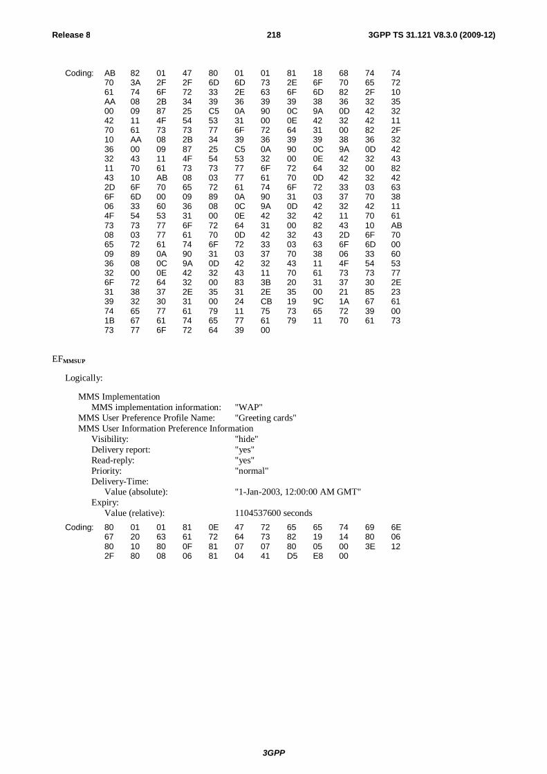
3GPP
Release 8 218 3GPP TS 31.121 V8.3.0 (2009-12)
Coding: AB 82 01 47 80 01 01 81 18 68 74 74 70 3A 2F 2F 6D 6D 73 2E 6F 70 65 72 61 74 6F 72 33 2E 63 6F 6D 82 2F 10 AA 08 2B 34 39 36 39 39 38 36 32 35 00 09 87 25 C5 0A 90 0C 9A 0D 42 32 42 11 4F 54 53 31 00 0E 42 32 42 11 70 61 73 73 77 6F 72 64 31 00 82 2F 10 AA 08 2B 34 39 36 39 39 38 36 32 36 00 09 87 25 C5 0A 90 0C 9A 0D 42 32 43 11 4F 54 53 32 00 0E 42 32 43 11 70 61 73 73 77 6F 72 64 32 00 82 43 10 AB 08 03 77 61 70 0D 42 32 42 2D 6F 70 65 72 61 74 6F 72 33 03 63 6F 6D 00 09 89 0A 90 31 03 37 70 38 06 33 60 36 08 0C 9A 0D 42 32 42 11 4F 54 53 31 00 0E 42 32 42 11 70 61 73 73 77 6F 72 64 31 00 82 43 10 AB 08 03 77 61 70 0D 42 32 43 2D 6F 70 65 72 61 74 6F 72 33 03 63 6F 6D 00 09 89 0A 90 31 03 37 70 38 06 33 60 36 08 0C 9A 0D 42 32 43 11 4F 54 53 32 00 0E 42 32 43 11 70 61 73 73 77 6F 72 64 32 00 83 3B 20 31 37 30 2E 31 38 37 2E 35 31 2E 35 00 21 85 23 39 32 30 31 00 24 CB 19 9C 1A 67 61 74 65 77 61 79 11 75 73 65 72 39 00 1B 67 61 74 65 77 61 79 11 70 61 73 73 77 6F 72 64 39 00
EFMMSUP
Logically:
MMS Implementation MMS implementation information: "WAP"
MMS User Preference Profile Name: "Greeting cards" MMS User Information Preference Information
Visibility: "hide" Delivery report: "yes" Read-reply: "yes" Priority: "normal" Delivery-Time:
Value (absolute): "1-Jan-2003, 12:00:00 AM GMT" Expiry:
Value (relative): 1104537600 seconds
Coding: 80 01 01 81 0E 47 72 65 65 74 69 6E 67 20 63 61 72 64 73 82 19 14 80 06 80 10 80 0F 81 07 07 80 05 00 3E 12 2F 80 08 06 81 04 41 D5 E8 00

3GPP
Release 8 219 3GPP TS 31.121 V8.3.0 (2009-12)
EFMMSUCP
Logically: MMS Connectivity Parameters
MMS Implementation MMS Implementation Information : "WAP"
MMS Relay/Server MMS Relay/Server Address "http://mms-operator3.com"
1st Interface to Core Network and Bearer Bearer: "GSM-CSD" Address: "+495251699" Type of address: "E164" Speed: "Autobauding" Call type: "ANALOG_MODEM" Authentication type: "PAP" Authentication id: "UDO_OTS1" Authentication pw: "Udo_password1"
2nd Interface to Core Network and Bearer Bearer: "GSM-CSD" Address: "+495251700" Type of address: "E164" Speed: "Autobauding" Call type: "ANALOG_MODEM" Authentication type: "PAP" Authentication id: "UDO_OTS2" Authentication pw: "Udo_password2"
3rd Interface to Core Network and Bearer Bearer: "GSM-GPRS" Address: "wap.B2P-operator3.com" Type of address: "APN" Call type: "ANALOG_MODEM" Delivery of erroneous SDU: "No" Residual Bit Error Rate: "1*10-5" SDU-Error-Ratio: "1*10-6" Traffic-class: "Interactive class" Maximum bit rate for downlink: "8 kbps" Authentication type: "PAP" Authentication id: "UDO_OTS1" Authentication pw: "Udo_password1"
4th Interface to Core Network and Bearer Bearer: "GSM-GPRS" Address: "wap.B2C-operator3.com" Type of address: "APN" Call type: "ANALOG_MODEM" Delivery of erroneous SDU: "No" Residual Bit Error Rate: "1*10-5" SDU-Error-Ratio: "1*10-6" Traffic-class: "Interactive class" Maximum bit rate for downlink: "8 kbps" Authentication type: "PAP" Authentication id: "UDO_OTS2" Authentication pw: "Udo_password2"
Gateway: Address: "170.187.51.5" Type of address: "Ipv4" Port : "9201" Service: "CO-WSP" Authentication type: "HTTP BASIC" Authentication id: "gateway_user9" Authentication pw: "gateway_password9"
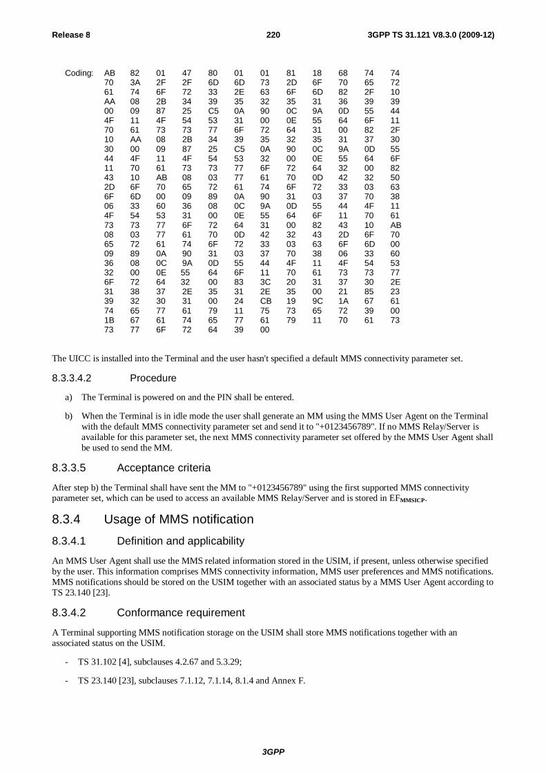
3GPP
Release 8 220 3GPP TS 31.121 V8.3.0 (2009-12)
Coding: AB 82 01 47 80 01 01 81 18 68 74 74 70 3A 2F 2F 6D 6D 73 2D 6F 70 65 72 61 74 6F 72 33 2E 63 6F 6D 82 2F 10 AA 08 2B 34 39 35 32 35 31 36 39 39 00 09 87 25 C5 0A 90 0C 9A 0D 55 44 4F 11 4F 54 53 31 00 0E 55 64 6F 11 70 61 73 73 77 6F 72 64 31 00 82 2F 10 AA 08 2B 34 39 35 32 35 31 37 30 30 00 09 87 25 C5 0A 90 0C 9A 0D 55 44 4F 11 4F 54 53 32 00 0E 55 64 6F 11 70 61 73 73 77 6F 72 64 32 00 82 43 10 AB 08 03 77 61 70 0D 42 32 50 2D 6F 70 65 72 61 74 6F 72 33 03 63 6F 6D 00 09 89 0A 90 31 03 37 70 38 06 33 60 36 08 0C 9A 0D 55 44 4F 11 4F 54 53 31 00 0E 55 64 6F 11 70 61 73 73 77 6F 72 64 31 00 82 43 10 AB 08 03 77 61 70 0D 42 32 43 2D 6F 70 65 72 61 74 6F 72 33 03 63 6F 6D 00 09 89 0A 90 31 03 37 70 38 06 33 60 36 08 0C 9A 0D 55 44 4F 11 4F 54 53 32 00 0E 55 64 6F 11 70 61 73 73 77 6F 72 64 32 00 83 3C 20 31 37 30 2E 31 38 37 2E 35 31 2E 35 00 21 85 23 39 32 30 31 00 24 CB 19 9C 1A 67 61 74 65 77 61 79 11 75 73 65 72 39 00 1B 67 61 74 65 77 61 79 11 70 61 73 73 77 6F 72 64 39 00
The UICC is installed into the Terminal and the user hasn't specified a default MMS connectivity parameter set.
8.3.3.4.2 Procedure
a) The Terminal is powered on and the PIN shall be entered.
b) When the Terminal is in idle mode the user shall generate an MM using the MMS User Agent on the Terminal with the default MMS connectivity parameter set and send it to "+0123456789". If no MMS Relay/Server is available for this parameter set, the next MMS connectivity parameter set offered by the MMS User Agent shall be used to send the MM.
8.3.3.5 Acceptance criteria
After step b) the Terminal shall have sent the MM to "+0123456789" using the first supported MMS connectivity parameter set, which can be used to access an available MMS Relay/Server and is stored in EFMMSICP.
8.3.4 Usage of MMS notification 8.3.4.1 Definition and applicability
An MMS User Agent shall use the MMS related information stored in the USIM, if present, unless otherwise specified by the user. This information comprises MMS connectivity information, MMS user preferences and MMS notifications. MMS notifications should be stored on the USIM together with an associated status by a MMS User Agent according to TS 23.140 [23].
8.3.4.2 Conformance requirement
A Terminal supporting MMS notification storage on the USIM shall store MMS notifications together with an associated status on the USIM.
- TS 31.102 [4], subclauses 4.2.67 and 5.3.29;
- TS 23.140 [23], subclauses 7.1.12, 7.1.14, 8.1.4 and Annex F.
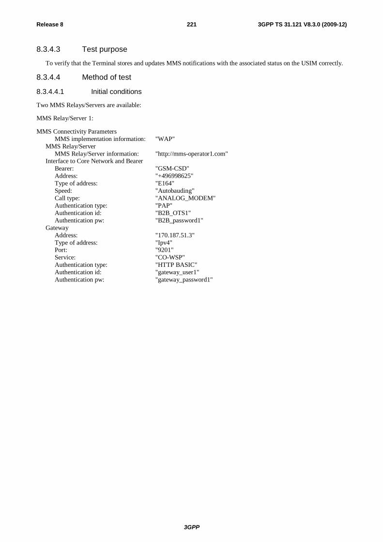
3GPP
Release 8 221 3GPP TS 31.121 V8.3.0 (2009-12)
8.3.4.3 Test purpose
To verify that the Terminal stores and updates MMS notifications with the associated status on the USIM correctly.
8.3.4.4 Method of test
8.3.4.4.1 Initial conditions
Two MMS Relays/Servers are available:
MMS Relay/Server 1:
MMS Connectivity Parameters MMS implementation information: "WAP"
MMS Relay/Server MMS Relay/Server information: "http://mms-operator1.com"
Interface to Core Network and Bearer Bearer: "GSM-CSD" Address: "+496998625" Type of address: "E164" Speed: "Autobauding" Call type: "ANALOG_MODEM" Authentication type: "PAP" Authentication id: "B2B_OTS1" Authentication pw: "B2B_password1"
Gateway Address: "170.187.51.3" Type of address: "Ipv4" Port: "9201" Service: "CO-WSP" Authentication type: "HTTP BASIC" Authentication id: "gateway_user1" Authentication pw: "gateway_password1"
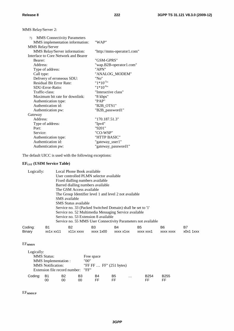
3GPP
Release 8 222 3GPP TS 31.121 V8.3.0 (2009-12)
MMS Relay/Server 2:
7) MMS Connectivity Parameters MMS implementation information: "WAP"
MMS Relay/Server MMS Relay/Server information: "http://mms-operator1.com"
Interface to Core Network and Bearer Bearer: "GSM-GPRS" Address: "wap.B2B-operator1.com" Type of address: "APN" Call type: "ANALOG_MODEM" Delivery of erroneous SDU: "No" Residual Bit Error Rate: "1*10-5" SDU-Error-Ratio: "1*10-6" Traffic-class: "Interactive class" Maximum bit rate for downlink: "8 kbps" Authentication type: "PAP" Authentication id: "B2B_OTS1" Authentication pw: "B2B_password1"
Gateway Address: "170.187.51.3" Type of address: "Ipv4" Port: "9201" Service: "CO-WSP" Authentication type: "HTTP BASIC" Authentication id: "gateway_user1" Authentication pw: "gateway_password1"
The default UICC is used with the following exceptions:
EFUST (USIM Service Table)
Logically: Local Phone Book available User controlled PLMN selector available Fixed dialling numbers available Barred dialling numbers available The GSM Access available The Group Identifier level 1 and level 2 not available SMS available SMS Status available Service no. 33 (Packed Switched Domain) shall be set to '1'
Service no. 52 Multimedia Messaging Service available Service no. 53 Extension 8 available Service no. 55 MMS User Connectivity Parameters not available
Coding: B1 B2 B3 B4 B5 B6 B7 Binary xx1x xx11 x11x xxxx xxxx 1x00 xxxx x1xx xxxx xxx1 xxxx xxxx x0x1 1xxx
EFMMSN
Logically: MMS Status: Free space MMS Implementation : "00" MMS Notification: "FF FF … FF" (251 bytes) Extension file record number: "FF"
Coding: B1 B2 B3 B4 B5 … B254 B255 00 00 00 FF FF FF FF
EFMMSUP
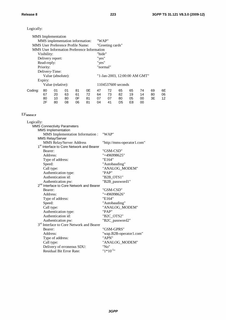
3GPP
Release 8 223 3GPP TS 31.121 V8.3.0 (2009-12)
Logically:
MMS Implementation MMS implementation information: "WAP"
MMS User Preference Profile Name: "Greeting cards" MMS User Information Preference Information
Visibility: "hide" Delivery report: "yes" Read-reply: "yes" Priority: "normal" Delivery-Time:
Value (absolute): "1-Jan-2003, 12:00:00 AM GMT" Expiry:
Value (relative): 1104537600 seconds
Coding: 80 01 01 81 0E 47 72 65 65 74 69 6E 67 20 63 61 72 64 73 82 19 14 80 06 80 10 80 0F 81 07 07 80 05 00 3E 12 2F 80 08 06 81 04 41 D5 E8 00
EFMMSICP
Logically: MMS Connectivity Parameters
MMS Implementation MMS Implementation Information : "WAP"
MMS Relay/Server MMS Relay/Server Address "http://mms-operator1.com"
1st Interface to Core Network and Bearer Bearer: "GSM-CSD" Address: "+496998625" Type of address: "E164" Speed: "Autobauding" Call type: "ANALOG_MODEM" Authentication type: "PAP" Authentication id: "B2B_OTS1" Authentication pw: "B2B_password1"
2nd Interface to Core Network and Bearer Bearer: "GSM-CSD" Address: "+496998626" Type of address: "E164" Speed: "Autobauding" Call type: "ANALOG_MODEM" Authentication type: "PAP" Authentication id: "B2C_OTS2" Authentication pw: "B2C_password2"
3rd Interface to Core Network and Bearer Bearer: "GSM-GPRS" Address: "wap.B2B-operator1.com" Type of address: "APN" Call type: "ANALOG_MODEM" Delivery of erroneous SDU: "No" Residual Bit Error Rate: "1*10-5"

3GPP
Release 8 224 3GPP TS 31.121 V8.3.0 (2009-12)
SDU-Error-Ratio: "1*10-6" Traffic-class: "Interactive class" Maximum bit rate for downlink: "8 kbps" Authentication type: "PAP" Authentication id: "B2B_OTS1" Authentication pw: "B2B_password1"
4th Interface to Core Network and Bearer Bearer: "GSM-GPRS" Address: "wap.B2C-operator1.com" Type of address: "APN" Call type: "ANALOG_MODEM" Delivery of erroneous SDU: "No" Residual Bit Error Rate: "1*10-5" SDU-Error-Ratio: "1*10-6" Traffic-class: "Interactive class" Maximum bit rate for downlink: "8 kbps" Authentication type: "PAP" Authentication id: "B2C_OTS2" Authentication pw: "B2C_password2"
Gateway: Address: "170.187.51.3" Type of address: "Ipv4" Port: "9201" Service: "CO-WSP" Authentication type: "HTTP BASIC" Authentication id: "gateway_user1" Authentication pw: "gateway_password1"
Coding: AB 82 01 47 80 01 01 81 18 68 74 74 70 3A 2F 2F 6D 6D 73 2E 6F 70 65 72 61 74 6F 72 31 2E 63 6F 6D 82 2F 10 AA 08 2B 34 39 36 39 39 38 36 32 35 00 09 87 25 C5 0A 90 0C 9A 0D 42 32 42 11 4F 54 53 31 00 0E 42 32 42 11 70 61 73 73 77 6F 72 64 31 00 82 2F 10 AA 08 2B 34 39 36 39 39 38 36 32 36 00 09 87 25 C5 0A 90 0C 9A 0D 42 32 43 11 4F 54 53 32 00 0E 42 32 43 11 70 61 73 73 77 6F 72 64 32 00 82 43 10 AB 08 03 77 61 70 0D 42 32 42 2D 6F 70 65 72 61 74 6F 72 31 03 63 6F 6D 00 09 89 0A 90 31 03 37 70 38 06 33 60 36 08 0C 9A 0D 42 32 42 11 4F 54 53 31 00 0E 42 32 42 11 70 61 73 73 77 6F 72 64 31 00 82 43 10 AB 08 03 77 61 70 0D 42 32 43 2D 6F 70 65 72 61 74 6F 72 31 03 63 6F 6D 00 09 89 0A 90 31 03 37 70 38 06 33 60 36 08 0C 9A 0D 42 32 43 11 4F 54 53 32 00 0E 42 32 43 11 70 61 73 73 77 6F 72 64 32 00 83 3C 20 31 37 30 2E 31 38 37 2E 35 31 2E 33 00 21 85 23 39 32 30 31 00 24 CB 19 9C 1A 67 61 74 65 77 61 79 11 75 73 65 72 31 00 1B 67 61 74 65 77 61 79 11 70 61 73 73 77 6F 72 64 31 00
EFEXT8
Logically: At least 10 records.
Record 1 to 10: Free space with 253 bytes for extension data
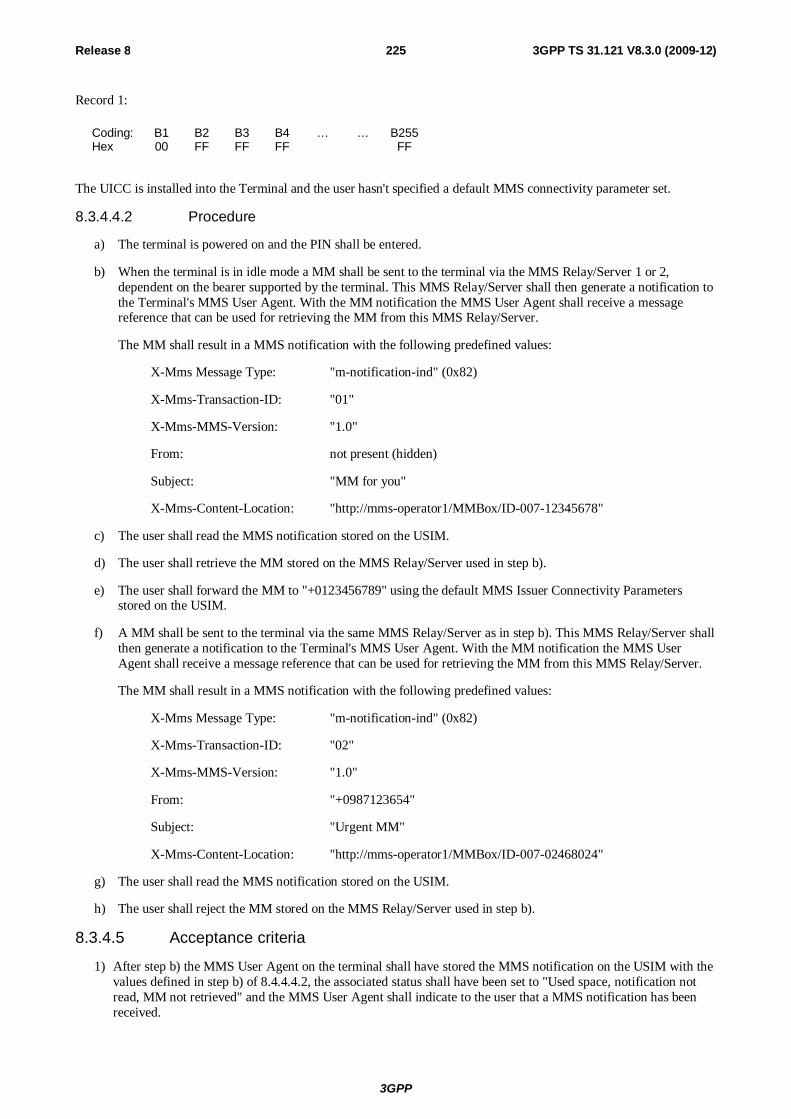
3GPP
Release 8 225 3GPP TS 31.121 V8.3.0 (2009-12)
Record 1:
Coding: B1 B2 B3 B4 … … B255 Hex 00 FF FF FF FF
The UICC is installed into the Terminal and the user hasn't specified a default MMS connectivity parameter set.
8.3.4.4.2 Procedure
a) The terminal is powered on and the PIN shall be entered.
b) When the terminal is in idle mode a MM shall be sent to the terminal via the MMS Relay/Server 1 or 2, dependent on the bearer supported by the terminal. This MMS Relay/Server shall then generate a notification to the Terminal's MMS User Agent. With the MM notification the MMS User Agent shall receive a message reference that can be used for retrieving the MM from this MMS Relay/Server.
The MM shall result in a MMS notification with the following predefined values:
X-Mms Message Type: "m-notification-ind" (0x82)
X-Mms-Transaction-ID: "01"
X-Mms-MMS-Version: "1.0"
From: not present (hidden)
Subject: "MM for you"
X-Mms-Content-Location: "http://mms-operator1/MMBox/ID-007-12345678"
c) The user shall read the MMS notification stored on the USIM.
d) The user shall retrieve the MM stored on the MMS Relay/Server used in step b).
e) The user shall forward the MM to "+0123456789" using the default MMS Issuer Connectivity Parameters stored on the USIM.
f) A MM shall be sent to the terminal via the same MMS Relay/Server as in step b). This MMS Relay/Server shall then generate a notification to the Terminal's MMS User Agent. With the MM notification the MMS User Agent shall receive a message reference that can be used for retrieving the MM from this MMS Relay/Server.
The MM shall result in a MMS notification with the following predefined values:
X-Mms Message Type: "m-notification-ind" (0x82)
X-Mms-Transaction-ID: "02"
X-Mms-MMS-Version: "1.0"
From: "+0987123654"
Subject: "Urgent MM"
X-Mms-Content-Location: "http://mms-operator1/MMBox/ID-007-02468024"
g) The user shall read the MMS notification stored on the USIM.
h) The user shall reject the MM stored on the MMS Relay/Server used in step b).
8.3.4.5 Acceptance criteria
1) After step b) the MMS User Agent on the terminal shall have stored the MMS notification on the USIM with the values defined in step b) of 8.4.4.4.2, the associated status shall have been set to "Used space, notification not read, MM not retrieved" and the MMS User Agent shall indicate to the user that a MMS notification has been received.

3GPP
Release 8 226 3GPP TS 31.121 V8.3.0 (2009-12)
2) After step c) the status of the MMS notification stored on the USIM shall have been set to "used space, notification read, MM not retrieved".
3) After step d) the MMS user agent shall have retrieved the MM from the MMS Relay/Server 1 and the status of the MMS notification stored on the USIM shall have either been set to "used space, notification read, MM retrieved" or the MMS notification shall have been deleted and the associated shall have been set to "Free space".
4) After step e) the terminal shall have read the set of MMS Issuer Connectivity Parameters stored first in EFMMSICP and shall have forward the MM to "+0123456789" using the MMS Relay/Server 1. The MMS notification shall have either been set to "used space, notification read, MM forwarded" or the MMS notification shall have been deleted and the associated shall have been set to "Free space".
5) After step f) the MMS User Agent on the terminal shall have stored the MMS notification on the USIM with the values defined in step f) of 8.4.4.4.2, the associated status shall have been set to "Used space, notification not read, MM not retrieved" and the MMS User Agent shall indicate to the user that a MMS notification has been received.
6) After step g) the status of the MMS notification stored on the USIM shall have been set to "used space, notification read, MM not retrieved".
7) After step h) the MMS user agent shall have not retrieved the MM from the MMS Relay/Server 1 and the status of the MMS notification stored on the USIM shall have either been set to "used space, notification read, MM rejected" or the MMS notification shall have been deleted and the associated shall have been set to "Free space".
8.4 UICC presence detection 8.4.1 Definition and applicability To ensure that the UICC has not been removed during a card session, the Terminal sends in case of inactivity on the UICC-Terminal interface, at frequent intervals, a STATUS command during each call.
This procedure shall be used in addition to a mechanical or other devices used to detect the removal of a UICC.
8.4.2 Conformance requirement A STATUS command shall be issued within all 30 second periods of inactivity on the UICC-Terminal interface during a call. Inactivity in this case is defined as starting at the end of the last communication or the last issued STATUS command. If no response data is received to this STATUS command, then the call shall be terminated as soon as possible but at least within 5s after the STATUS command has been sent. If the DF indicated in response to a STATUS command is not the same as that which was indicated in the previous response, or accessed by the previous command, then the call shall be terminated as soon as possible but at least within 5 seconds after the response data has been received.
- TS 31.102 [4], subclauses 5.1.9
- ETSI TS 102 221 [5], clause 14.5.2.
8.4.3 Test purpose 1) To verify that there are no periods of inactivity on the UICC-Terminal interface greater than 30 seconds during a
call.
2) To verify that the terminal terminates a call within 5 s at the latest after having received an invalid response to the STATUS command.
8.4.4 Method of test 8.4.4.1 Initial conditions
The terminal shall be connected to the UICC simulator. All elementary files shall be coded as default.
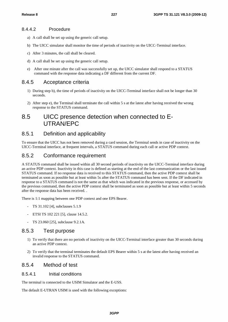
3GPP
Release 8 227 3GPP TS 31.121 V8.3.0 (2009-12)
8.4.4.2 Procedure
a) A call shall be set up using the generic call setup.
b) The UICC simulator shall monitor the time of periods of inactivity on the UICC-Terminal interface.
c) After 3 minutes, the call shall be cleared.
d) A call shall be set up using the generic call setup.
e) After one minute after the call was successfully set up, the UICC simulator shall respond to a STATUS command with the response data indicating a DF different from the current DF.
8.4.5 Acceptance criteria 1) During step b), the time of periods of inactivity on the UICC-Terminal interface shall not be longer than 30
seconds.
2) After step e), the Terminal shall terminate the call within 5 s at the latest after having received the wrong response to the STATUS command.
8.5 UICC presence detection when connected to E-UTRAN/EPC
8.5.1 Definition and applicability To ensure that the UICC has not been removed during a card session, the Terminal sends in case of inactivity on the UICC-Terminal interface, at frequent intervals, a STATUS command during each call or active PDP context.
8.5.2 Conformance requirement A STATUS command shall be issued within all 30 second periods of inactivity on the UICC-Terminal interface during an active PDP context. Inactivity in this case is defined as starting at the end of the last communication or the last issued STATUS command. If no response data is received to this STATUS command, then the active PDP context shall be terminated as soon as possible but at least within 5s after the STATUS command has been sent. If the DF indicated in response to a STATUS command is not the same as that which was indicated in the previous response, or accessed by the previous command, then the active PDP context shall be terminated as soon as possible but at least within 5 seconds after the response data has been received. .
There is 1:1 mapping between one PDP context and one EPS Bearer.
- TS 31.102 [4], subclauses 5.1.9
- ETSI TS 102 221 [5], clause 14.5.2.
- TS 23.060 [25], subclause 9.2.1A.
8.5.3 Test purpose 1) To verify that there are no periods of inactivity on the UICC-Terminal interface greater than 30 seconds during
an active PDP context.
2) To verify that the terminal terminates the default EPS Bearer within 5 s at the latest after having received an invalid response to the STATUS command.
8.5.4 Method of test 8.5.4.1 Initial conditions
The terminal is connected to the USIM Simulator and the E-USS.
The default E-UTRAN USIM is used with the following exceptions:
3GPP
Release 8 228 3GPP TS 31.121 V8.3.0 (2009-12)
8.5.4.2 Procedure
a) The terminal is switched on, performs the Attach procedure to the E-USS and establishes the default EPS bearer.
b) The UICC simulator shall monitor the time of periods of inactivity on the UICC-Terminal interface.
c) Step b) shall be performed for 3 minutes.
d) After one minute after the end of step c), the UICC simulator shall respond to a STATUS command with the response data indicating a DF different from the current DF.
8.5.5 Acceptance criteria 1) During step c), the time of periods of inactivity on the UICC-Terminal interface shall not be longer than 30
seconds.
2) After step d), the Terminal shall terminate the default EPS bearer within 5 s at the latest after having received the wrong response to the STATUS command.
9 USIM service handling 9.1 Access Point Name Control List handling
9.1.1 Access Point Name Control List handling for terminals supporting ACL
9.1.1.1 Definition and applicability
This EFACL contains the list of allowed APNs (Access Point Names).When the APN Control List service is enabled, the ME shall check that the entire APN of any PDP context is listed in EFACL before requesting this PDP context activation from the network. If the APN is not present in EFACL, the ME shall not request the corresponding PDP context activation from the network.
9.1.1.2 Conformance requirement
The terminal shall support the APN Control List service as defined in TS 31.102 [4], subclauses 5.1.1.2 and 5.3.14.
Reference:
- TS 31.102 [4], subclauses 4.2.8, 4.2.48, 5.1.1.2 and 5.3.14;
- TS 23.060 [25], subclause 9.2.
9.1.1.3 Test purpose
1) To verify that the terminal takes into account the status of the APN Control List service as indicated in EFUST and EFEST.
2) To verify that the terminal checks that the entire APN of any PDP context is listed in EFACL before requesting this PDP context activation from the network if the ACL service is enabled.
3) To verify that the terminal does not request the corresponding PDP context activation from the network if the ACL service is enabled and the APN is not present in EFACL.
9.1.1.4 Method of test
9.1.1.4.1 Initial conditions
The terminal is connected to the USIM Simulator and the (U)SS.
The default USIM is used with the following exceptions:
3GPP
Release 8 229 3GPP TS 31.121 V8.3.0 (2009-12)
The APN Control List (ACL) shall be allocated and activated in the USIM Service Table and enabled in the Enabled Service Table.
EFACL shall be present with the following values:
EFACL (Access Point Control List)
Logically: Number of available bytes: 64 Number of APNs: 3 1st APN: test.test 2nd APN: 3gpp.test 3rd APN: 2gpp.test
Byte: B1 B2 B3 B4 B5 B6 B7 B8 B9 B10 B11 B12 Coding: 03 DD 0A 04 74 65 73 74 04 74 65 73 B13 B14 B15 B16 B17 B18 B19 B20 B21 B22 B23 B24 74 DD 0A 04 33 67 70 70 04 74 65 73 B25 B26 B27 B28 B29 B30 B31 B32 B33 B34 B35 B36 74 DD 0A 04 32 67 70 70 04 74 65 73 B37 B38 … B64 74 FF … FF
9.1.1.4.2 Procedure
a) The terminal is switched on and the USIM application shall be activated.
b) The user shall request a PDP context activation to "1gpp.test".
c) The user shall request a PDP context activation to "3gpp.test".
d) The user shall deactivate the PDP context.
e) The user shall disable the APN Control List service. When prompted to enter PIN2, the user shall present the correct PIN2 value.
f) The user shall request a PDP context activation to "1gpp.test".
g) The user shall deactivate the PDP context and shall switch the terminal off and then switch on again.
h) The user shall enable the APN Control List service. When prompted to enter PIN2, the user shall present the correct PIN2 value.
i) The user shall request a PDP context activation to "1ppp.net".
j) The terminal is switched off and on.
k) The user shall add the APN "1ppp.net" to the APN Control List. When prompted to enter PIN2, the user shall present the correct PIN2 value.
l) The user shall request a PDP context activation to "1ppp.net".
m) The user shall deactivate the PDP context and switch off the terminal.
9.1.1.5 Acceptance criteria
1) After step a) the terminal shall have activated the USIM application, shall have read the status of the ACL service in EFUST and EFEST and be in updated idle mode on the (U)SS.
2) The terminal shall have not requested a PDP context activation in step b).
3) After step c) the PDP context shall have been activated.
4) After step d) the PDP context shall have been deactivated.
3GPP
Release 8 230 3GPP TS 31.121 V8.3.0 (2009-12)
5) After step e) the APN Control List service shall have been set to disabled in EFEST.
6) After step f) the PDP context shall have been activated.
7) After step g) the PDP context shall have been deactivated.
8) After step h) the APN Control List service shall have been set to enabled in EFEST.
9) The terminal shall not have requested a PDP context activation in step i).
10) After step k) the APN "1ppp.net" shall have been added to the APN Control List in EFACL.
11) After step l) the PDP context shall have been activated.
9.1.2 Network provided APN handling for terminals supporting ACL
9.1.2.1 Definition and applicability
This EFACL contains the list of allowed APNs (Access Point Names).When the APN Control List service is enabled, the ME shall check that the entire APN of any PDP context is listed in EFACL before requesting this PDP context activation from the network. If the APN is not present in EFACL, the ME shall not request the corresponding PDP context activation from the network.
In the case that the APN Control List is enabled and no APN is indicated in the PDP context request, indicating that a network provided APN is to be used, then the ME shall only request the PDP context activation if "network provided APN" is contained within EFACL.
9.1.2.2 Conformance requirement
The terminal shall support the APN Control List service as defined in TS 31.102 [4], subclauses 5.1.1.2 and 5.3.14.
Reference:
- TS 31.102 [4], subclauses 4.2.8, 4.2.48, 5.1.1.2 and 5.3.14;
- TS 23.060 [25], subclause 9.2.
9.1.2.3 Test purpose
1) To verify that if ACL is enabled and if no APN is indicated in the PDP context the terminal request the PDP context activation only if "network provided APN" is contained within EFACL.
2) To verify that the user is able to set an APN in EFACL entry to the value "network provided APN".
3) To verify that the minimum set of APN entries in EFACL is ensured when the user deletes APN entries.
9.1.2.4 Method of test
9.1.2.4.1 Initial conditions
The terminal is connected to the USIM Simulator and the (U)SS.
The default USIM is used with the following exceptions:
The APN Control List (ACL) shall be allocated and activated in the USIM Service Table and enabled in the Enabled Service Table.
EFACL shall be present with the following values:
EFACL (Access Point Control List)
Logically: Number of available bytes: 64 Number of APNs: 3 1st APN: test.test 2nd APN: 3gpp.test
3GPP
Release 8 231 3GPP TS 31.121 V8.3.0 (2009-12)
3rd APN: 2gpp.test
Byte: B1 B2 B3 B4 B5 B6 B7 B8 B9 B10 B11 B12 Coding: 03 DD 0A 04 74 65 73 74 04 74 65 73 B13 B14 B15 B16 B17 B18 B19 B20 B21 B22 B23 B24 74 DD 0A 04 33 67 70 70 04 74 65 73 B25 B26 B27 B28 B29 B30 B31 B32 B33 B34 B35 B36 74 DD 0A 04 32 67 70 70 04 74 65 73 B37 B38 … B64 74 FF … FF
9.1.2.4.2 Procedure
a) The terminal is switched on and the USIM application shall be activated.
b) The user shall add "network provided APN" to the APN Control List in EFACL by using an MMI dependent option in the terminal. When prompted to enter PIN2, the user shall present the correct PIN2 value.
c) The user shall request a PDP context activation to "3gpp.test".
d) The user shall deactivate the PDP context.
e) The user shall request a PDP context activation without indicating an APN.
f) The user shall deactivate the PDP context.
g) The user shall delete "network provided APN" from the APN Control List in EFACL by using an MMI dependent option in the terminal. When prompted to enter PIN2, the user shall present the correct PIN2 value.
h) The user shall request a PDP context activation to "3gpp.test".
i) The user shall deactivate the PDP context.
j) The user shall request a PDP context activation without indicating an APN.
k) The user shall try to delete all APNs from the APN Control List in EFACL by using an MMI dependent option in the terminal. When the terminal indicates that at least one APN entry shall remain, the user shall set this entry to "network provided APN". When prompted to enter PIN2, the user shall present the correct PIN2 value.
l) The user shall switch off the terminal.
9.1.2.5 Acceptance criteria
1) After step a) the terminal shall have activated the USIM application, shall have read the status of the ACL service in EFUST and EFEST and be in updated idle mode on the (U)SS.
2) After step b) EFACL shall contain an entry for "network provided APN".
3) After step c) the PDP context shall have been activated.
4) After step d) the PDP context shall have been deactivated.
5) After step e) the PDP context shall have been activated.
6) After step f) the PDP context shall have been deactivated.
7) After step g) EFACL shall not contain an entry for "network provided APN".
8) After step h) the PDP context shall have been activated.
9) After step i) the PDP context shall have been deactivated.
10) The terminal shall have not requested a PDP context activation in step j).
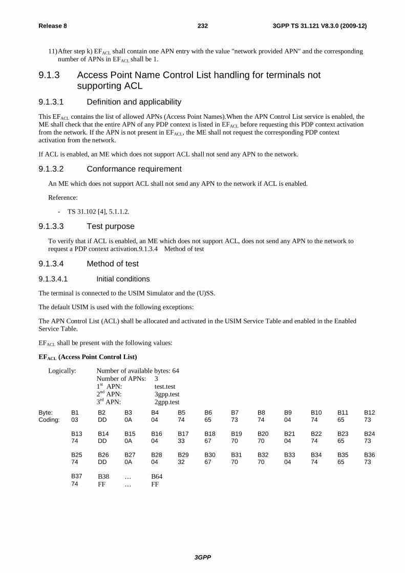
3GPP
Release 8 232 3GPP TS 31.121 V8.3.0 (2009-12)
11) After step k) EFACL shall contain one APN entry with the value "network provided APN" and the corresponding number of APNs in EFACL shall be 1.
9.1.3 Access Point Name Control List handling for terminals not supporting ACL
9.1.3.1 Definition and applicability
This EFACL contains the list of allowed APNs (Access Point Names).When the APN Control List service is enabled, the ME shall check that the entire APN of any PDP context is listed in EFACL before requesting this PDP context activation from the network. If the APN is not present in EFACL, the ME shall not request the corresponding PDP context activation from the network.
If ACL is enabled, an ME which does not support ACL shall not send any APN to the network.
9.1.3.2 Conformance requirement
An ME which does not support ACL shall not send any APN to the network if ACL is enabled.
Reference:
- TS 31.102 [4], 5.1.1.2.
9.1.3.3 Test purpose
To verify that if ACL is enabled, an ME which does not support ACL, does not send any APN to the network to request a PDP context activation.9.1.3.4 Method of test
9.1.3.4 Method of test
9.1.3.4.1 Initial conditions
The terminal is connected to the USIM Simulator and the (U)SS.
The default USIM is used with the following exceptions:
The APN Control List (ACL) shall be allocated and activated in the USIM Service Table and enabled in the Enabled Service Table.
EFACL shall be present with the following values:
EFACL (Access Point Control List)
Logically: Number of available bytes: 64 Number of APNs: 3 1st APN: test.test 2nd APN: 3gpp.test 3rd APN: 2gpp.test
Byte: B1 B2 B3 B4 B5 B6 B7 B8 B9 B10 B11 B12 Coding: 03 DD 0A 04 74 65 73 74 04 74 65 73 B13 B14 B15 B16 B17 B18 B19 B20 B21 B22 B23 B24 74 DD 0A 04 33 67 70 70 04 74 65 73 B25 B26 B27 B28 B29 B30 B31 B32 B33 B34 B35 B36 74 DD 0A 04 32 67 70 70 04 74 65 73 B37 B38 … B64 74 FF … FF
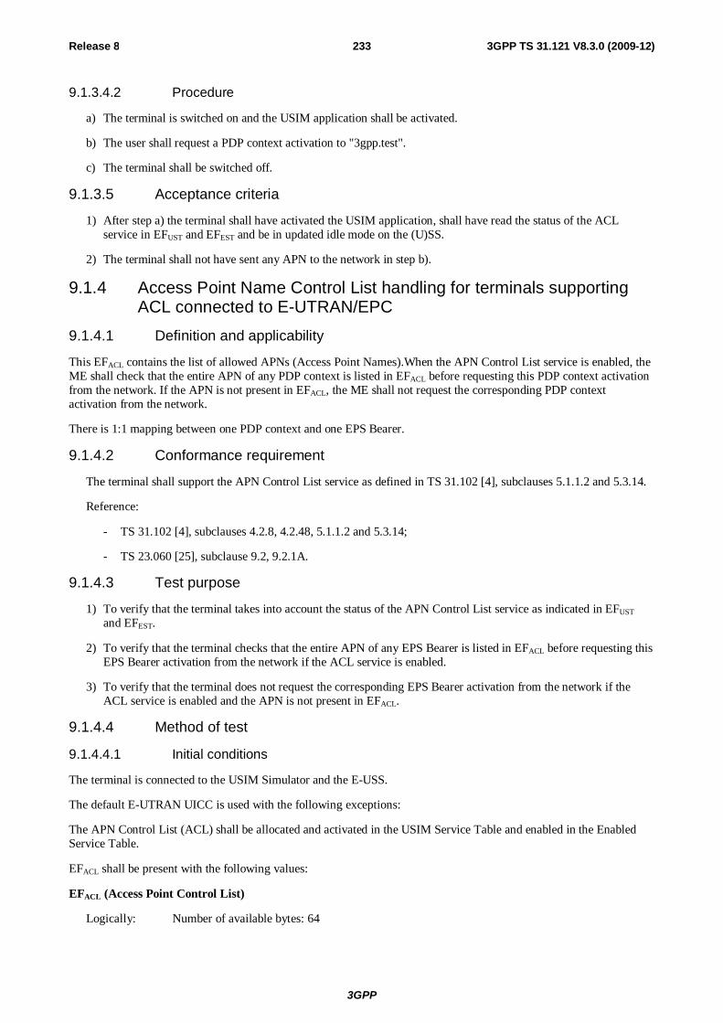
3GPP
Release 8 233 3GPP TS 31.121 V8.3.0 (2009-12)
9.1.3.4.2 Procedure
a) The terminal is switched on and the USIM application shall be activated.
b) The user shall request a PDP context activation to "3gpp.test".
c) The terminal shall be switched off.
9.1.3.5 Acceptance criteria
1) After step a) the terminal shall have activated the USIM application, shall have read the status of the ACL service in EFUST and EFEST and be in updated idle mode on the (U)SS.
2) The terminal shall not have sent any APN to the network in step b).
9.1.4 Access Point Name Control List handling for terminals supporting ACL connected to E-UTRAN/EPC
9.1.4.1 Definition and applicability
This EFACL contains the list of allowed APNs (Access Point Names).When the APN Control List service is enabled, the ME shall check that the entire APN of any PDP context is listed in EFACL before requesting this PDP context activation from the network. If the APN is not present in EFACL, the ME shall not request the corresponding PDP context activation from the network.
There is 1:1 mapping between one PDP context and one EPS Bearer.
9.1.4.2 Conformance requirement
The terminal shall support the APN Control List service as defined in TS 31.102 [4], subclauses 5.1.1.2 and 5.3.14.
Reference:
- TS 31.102 [4], subclauses 4.2.8, 4.2.48, 5.1.1.2 and 5.3.14;
- TS 23.060 [25], subclause 9.2, 9.2.1A.
9.1.4.3 Test purpose
1) To verify that the terminal takes into account the status of the APN Control List service as indicated in EFUST and EFEST.
2) To verify that the terminal checks that the entire APN of any EPS Bearer is listed in EFACL before requesting this EPS Bearer activation from the network if the ACL service is enabled.
3) To verify that the terminal does not request the corresponding EPS Bearer activation from the network if the ACL service is enabled and the APN is not present in EFACL.
9.1.4.4 Method of test
9.1.4.4.1 Initial conditions
The terminal is connected to the USIM Simulator and the E-USS.
The default E-UTRAN UICC is used with the following exceptions:
The APN Control List (ACL) shall be allocated and activated in the USIM Service Table and enabled in the Enabled Service Table.
EFACL shall be present with the following values:
EFACL (Access Point Control List)
Logically: Number of available bytes: 64
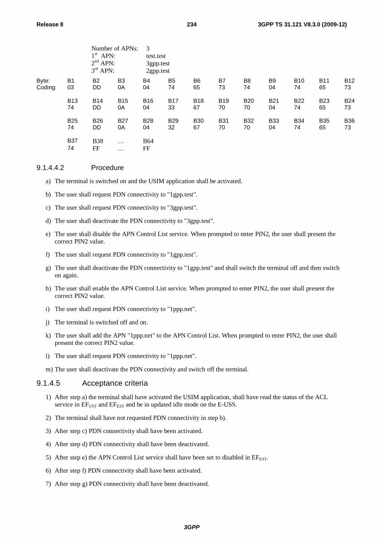
3GPP
Release 8 234 3GPP TS 31.121 V8.3.0 (2009-12)
Number of APNs: 3 1st APN: test.test 2nd APN: 3gpp.test 3rd APN: 2gpp.test
Byte: B1 B2 B3 B4 B5 B6 B7 B8 B9 B10 B11 B12 Coding: 03 DD 0A 04 74 65 73 74 04 74 65 73 B13 B14 B15 B16 B17 B18 B19 B20 B21 B22 B23 B24 74 DD 0A 04 33 67 70 70 04 74 65 73 B25 B26 B27 B28 B29 B30 B31 B32 B33 B34 B35 B36 74 DD 0A 04 32 67 70 70 04 74 65 73 B37 B38 … B64 74 FF … FF
9.1.4.4.2 Procedure
a) The terminal is switched on and the USIM application shall be activated.
b) The user shall request PDN connectivity to "1gpp.test".
c) The user shall request PDN connectivity to "3gpp.test".
d) The user shall deactivate the PDN connectivity to "3gpp.test".
e) The user shall disable the APN Control List service. When prompted to enter PIN2, the user shall present the correct PIN2 value.
f) The user shall request PDN connectivity to "1gpp.test".
g) The user shall deactivate the PDN connectivity to "1gpp.test" and shall switch the terminal off and then switch on again.
h) The user shall enable the APN Control List service. When prompted to enter PIN2, the user shall present the correct PIN2 value.
i) The user shall request PDN connectivity to "1ppp.net".
j) The terminal is switched off and on.
k) The user shall add the APN "1ppp.net" to the APN Control List. When prompted to enter PIN2, the user shall present the correct PIN2 value.
l) The user shall request PDN connectivity to "1ppp.net".
m) The user shall deactivate the PDN connectivity and switch off the terminal.
9.1.4.5 Acceptance criteria
1) After step a) the terminal shall have activated the USIM application, shall have read the status of the ACL service in EFUST and EFEST and be in updated idle mode on the E-USS.
2) The terminal shall have not requested PDN connectivity in step b).
3) After step c) PDN connectivity shall have been activated.
4) After step d) PDN connectivity shall have been deactivated.
5) After step e) the APN Control List service shall have been set to disabled in EFEST.
6) After step f) PDN connectivity shall have been activated.
7) After step g) PDN connectivity shall have been deactivated.

3GPP
Release 8 235 3GPP TS 31.121 V8.3.0 (2009-12)
8) After step h) the APN Control List service shall have been set to enabled in EFEST.
9) The terminal shall not have requested PDN connectivity in step i).
10) After step k) the APN "1ppp.net" shall have been added to the APN Control List in EFACL.
11) After step l) PDN connectivity shall have been activated.
9.1.5 Network provided APN handling for terminals supporting ACL connected to E-UTRAN/EPC
9.1.5.1 Definition and applicability
This EFACL contains the list of allowed APNs (Access Point Names).When the APN Control List service is enabled, the ME shall check that the entire APN of any PDP context is listed in EFACL before requesting this PDP context activation from the network. If the APN is not present in EFACL, the ME shall not request the corresponding PDP context activation from the network.
In the case that the APN Control List is enabled and no APN is indicated in the PDP context request, indicating that a network provided APN is to be used, then the ME shall only request the PDP context activation if "network provided APN" is contained within EFACL.
There is 1:1 mapping between one PDP context and one EPS Bearer.
9.1.5.2 Conformance requirement
The terminal shall support the APN Control List service as defined in TS 31.102 [4], subclauses 5.1.1.2 and 5.3.14.
Reference:
- TS 31.102 [4], subclauses 4.2.8, 4.2.48, 5.1.1.2 and 5.3.14;
- TS 23.060 [25], subclause 9.2, 9.2.1A.
9.1.5.3 Test purpose
1) To verify that if ACL is enabled and if no APN is indicated in the EPS Bearer the terminal request the EPS Bearer activation only if "network provided APN" is contained within EFACL.
2) To verify that the user is able to set an APN in EFACL entry to the value "network provided APN".
3) To verify that the minimum set of APN entries in EFACL is ensured when the user deletes APN entries.
9.1.5.4 Method of test
9.1.5.4.1 Initial conditions
The terminal is connected to the USIM Simulator and the E-USS.
The default E-UTRAN UICC is used with the following exceptions:
The APN Control List (ACL) shall be allocated and activated in the USIM Service Table and enabled in the Enabled Service Table.
EFACL shall be present with the following values:
EFACL (Access Point Control List)
Logically: Number of available bytes: 64 Number of APNs: 3 1st APN: test.test 2nd APN: 3gpp.test 3rd APN: 2gpp.test
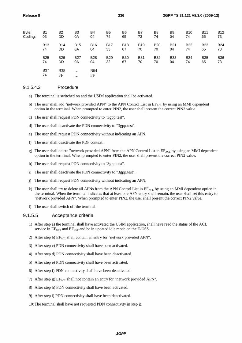
3GPP
Release 8 236 3GPP TS 31.121 V8.3.0 (2009-12)
Byte: B1 B2 B3 B4 B5 B6 B7 B8 B9 B10 B11 B12 Coding: 03 DD 0A 04 74 65 73 74 04 74 65 73 B13 B14 B15 B16 B17 B18 B19 B20 B21 B22 B23 B24 74 DD 0A 04 33 67 70 70 04 74 65 73 B25 B26 B27 B28 B29 B30 B31 B32 B33 B34 B35 B36 74 DD 0A 04 32 67 70 70 04 74 65 73 B37 B38 … B64 74 FF … FF
9.1.5.4.2 Procedure
a) The terminal is switched on and the USIM application shall be activated.
b) The user shall add "network provided APN" to the APN Control List in EFACL by using an MMI dependent option in the terminal. When prompted to enter PIN2, the user shall present the correct PIN2 value.
c) The user shall request PDN connectivity to "3gpp.test".
d) The user shall deactivate the PDN connectivity to "3gpp.test".
e) The user shall request PDN connectivity without indicating an APN.
f) The user shall deactivate the PDP context.
g) The user shall delete "network provided APN" from the APN Control List in EFACL by using an MMI dependent option in the terminal. When prompted to enter PIN2, the user shall present the correct PIN2 value.
h) The user shall request PDN connectivity to "3gpp.test".
i) The user shall deactivate the PDN connectivity to "3gpp.test".
j) The user shall request PDN connectivity without indicating an APN.
k) The user shall try to delete all APNs from the APN Control List in EFACL by using an MMI dependent option in the terminal. When the terminal indicates that at least one APN entry shall remain, the user shall set this entry to "network provided APN". When prompted to enter PIN2, the user shall present the correct PIN2 value.
l) The user shall switch off the terminal.
9.1.5.5 Acceptance criteria
1) After step a) the terminal shall have activated the USIM application, shall have read the status of the ACL service in EFUST and EFEST and be in updated idle mode on the E-USS.
2) After step b) EFACL shall contain an entry for "network provided APN".
3) After step c) PDN connectivity shall have been activated.
4) After step d) PDN connectivity shall have been deactivated.
5) After step e) PDN connectivity shall have been activated.
6) After step f) PDN connectivity shall have been deactivated.
7) After step g) EFACL shall not contain an entry for "network provided APN".
8) After step h) PDN connectivity shall have been activated.
9) After step i) PDN connectivity shall have been deactivated.
10) The terminal shall have not requested PDN connectivity in step j).
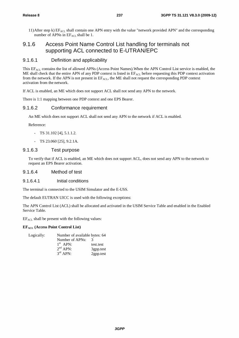
3GPP
Release 8 237 3GPP TS 31.121 V8.3.0 (2009-12)
11) After step k) EFACL shall contain one APN entry with the value "network provided APN" and the corresponding number of APNs in EFACL shall be 1.
9.1.6 Access Point Name Control List handling for terminals not supporting ACL connected to E-UTRAN/EPC
9.1.6.1 Definition and applicability
This EFACL contains the list of allowed APNs (Access Point Names).When the APN Control List service is enabled, the ME shall check that the entire APN of any PDP context is listed in EFACL before requesting this PDP context activation from the network. If the APN is not present in EFACL, the ME shall not request the corresponding PDP context activation from the network.
If ACL is enabled, an ME which does not support ACL shall not send any APN to the network.
There is 1:1 mapping between one PDP context and one EPS Bearer.
9.1.6.2 Conformance requirement
An ME which does not support ACL shall not send any APN to the network if ACL is enabled.
Reference:
- TS 31.102 [4], 5.1.1.2.
- TS 23.060 [25], 9.2.1A.
9.1.6.3 Test purpose
To verify that if ACL is enabled, an ME which does not support ACL, does not send any APN to the network to request an EPS Bearer activation.
9.1.6.4 Method of test
9.1.6.4.1 Initial conditions
The terminal is connected to the USIM Simulator and the E-USS.
The default EUTRAN UICC is used with the following exceptions:
The APN Control List (ACL) shall be allocated and activated in the USIM Service Table and enabled in the Enabled Service Table.
EFACL shall be present with the following values:
EFACL (Access Point Control List)
Logically: Number of available bytes: 64 Number of APNs: 3 1st APN: test.test 2nd APN: 3gpp.test 3rd APN: 2gpp.test
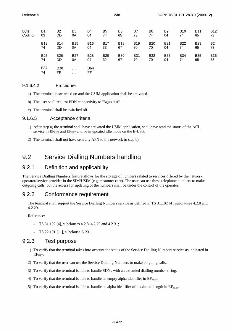
3GPP
Release 8 238 3GPP TS 31.121 V8.3.0 (2009-12)
Byte: B1 B2 B3 B4 B5 B6 B7 B8 B9 B10 B11 B12 Coding: 03 DD 0A 04 74 65 73 74 04 74 65 73 B13 B14 B15 B16 B17 B18 B19 B20 B21 B22 B23 B24 74 DD 0A 04 33 67 70 70 04 74 65 73 B25 B26 B27 B28 B29 B30 B31 B32 B33 B34 B35 B36 74 DD 0A 04 32 67 70 70 04 74 65 73 B37 B38 … B64 74 FF … FF
9.1.6.4.2 Procedure
a) The terminal is switched on and the USIM application shall be activated.
b) The user shall request PDN connectivity to "3gpp.test".
c) The terminal shall be switched off.
9.1.6.5 Acceptance criteria
1) After step a) the terminal shall have activated the USIM application, shall have read the status of the ACL service in EFUST and EFEST and be in updated idle mode on the E-USS.
2) The terminal shall not have sent any APN to the network in step b).
9.2 Service Dialling Numbers handling 9.2.1 Definition and applicability The Service Dialling Numbers feature allows for the storage of numbers related to services offered by the network operator/service provider in the SIM/USIM (e.g. customer care). The user can use these telephone numbers to make outgoing calls, but the access for updating of the numbers shall be under the control of the operator.
9.2.2 Conformance requirement The terminal shall support the Service Dialling Numbers service as defined in TS 31.102 [4], subclauses 4.2.8 and 4.2.29.
Reference:
- TS 31.102 [4], subclauses 4.2.8, 4.2.29 and 4.2.31;
- TS 22.101 [11], subclause A.23.
9.2.3 Test purpose 1) To verify that the terminal takes into account the status of the Service Dialling Numbers service as indicated in
EFUST.
2) To verify that the user can use the Service Dialling Numbers to make outgoing calls.
3) To verify that the terminal is able to handle SDNs with an extended dialling number string.
4) To verify that the terminal is able to handle an empty alpha identifier in EFSDN.
5) To verify that the terminal is able to handle an alpha identifier of maximum length in EFSDN.
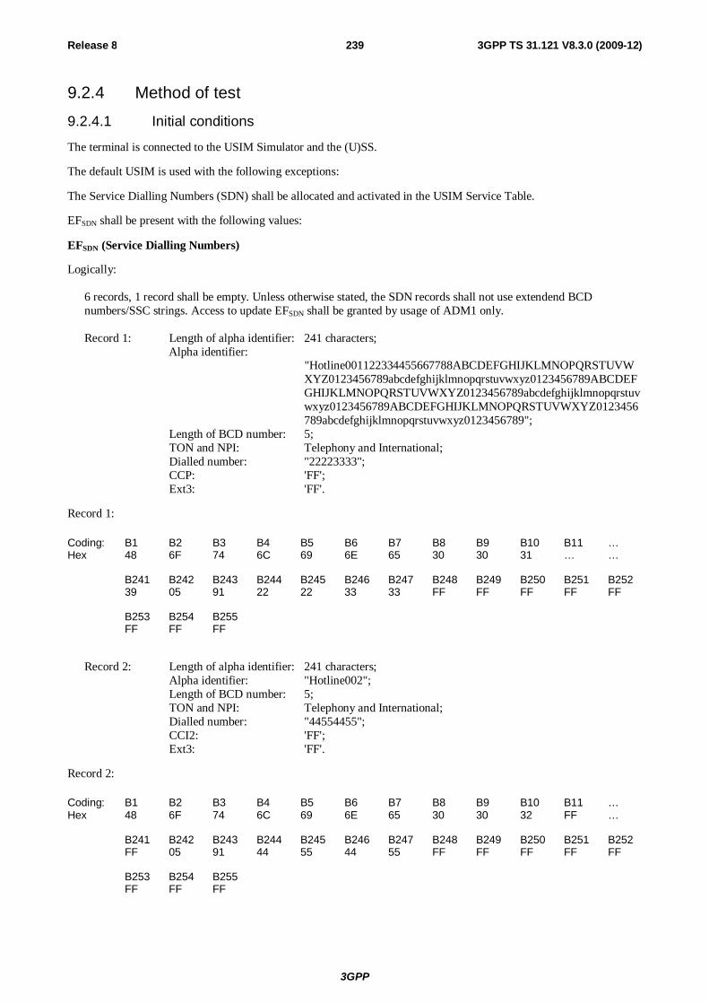
3GPP
Release 8 239 3GPP TS 31.121 V8.3.0 (2009-12)
9.2.4 Method of test
9.2.4.1 Initial conditions
The terminal is connected to the USIM Simulator and the (U)SS.
The default USIM is used with the following exceptions:
The Service Dialling Numbers (SDN) shall be allocated and activated in the USIM Service Table.
EFSDN shall be present with the following values:
EFSDN (Service Dialling Numbers)
Logically:
6 records, 1 record shall be empty. Unless otherwise stated, the SDN records shall not use extendend BCD numbers/SSC strings. Access to update EFSDN shall be granted by usage of ADM1 only. Record 1: Length of alpha identifier: 241 characters;
Alpha identifier: "Hotline001122334455667788ABCDEFGHIJKLMNOPQRSTUVWXYZ0123456789abcdefghijklmnopqrstuvwxyz0123456789ABCDEFGHIJKLMNOPQRSTUVWXYZ0123456789abcdefghijklmnopqrstuvwxyz0123456789ABCDEFGHIJKLMNOPQRSTUVWXYZ0123456789abcdefghijklmnopqrstuvwxyz0123456789";
Length of BCD number: 5; TON and NPI: Telephony and International; Dialled number: "22223333"; CCP: 'FF'; Ext3: 'FF'.
Record 1:
Coding: B1 B2 B3 B4 B5 B6 B7 B8 B9 B10 B11 … Hex 48 6F 74 6C 69 6E 65 30 30 31 … … B241 B242 B243 B244 B245 B246 B247 B248 B249 B250 B251 B252 39 05 91 22 22 33 33 FF FF FF FF FF B253 B254 B255 FF FF FF
Record 2: Length of alpha identifier: 241 characters; Alpha identifier: "Hotline002"; Length of BCD number: 5; TON and NPI: Telephony and International; Dialled number: "44554455"; CCI2: 'FF'; Ext3: 'FF'.
Record 2:
Coding: B1 B2 B3 B4 B5 B6 B7 B8 B9 B10 B11 … Hex 48 6F 74 6C 69 6E 65 30 30 32 FF … B241 B242 B243 B244 B245 B246 B247 B248 B249 B250 B251 B252 FF 05 91 44 55 44 55 FF FF FF FF FF B253 B254 B255 FF FF FF
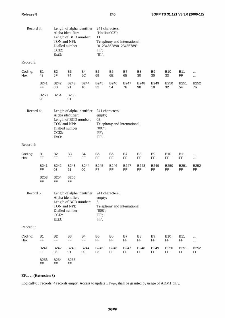
3GPP
Release 8 240 3GPP TS 31.121 V8.3.0 (2009-12)
Record 3: Length of alpha identifier: 241 characters; Alpha identifier: "Hotline003"; Length of BCD number: 11; TON and NPI: Telephony and International; Dialled number: "01234567890123456789"; CCI2: 'FF'; Ext3: "01".
Record 3:
Coding: B1 B2 B3 B4 B5 B6 B7 B8 B9 B10 B11 … Hex 48 6F 74 6C 69 6E 65 30 30 33 FF … B241 B242 B243 B244 B245 B246 B247 B248 B249 B250 B251 B252 FF 0B 91 10 32 54 76 98 10 32 54 76 B253 B254 B255 98 FF 01
Record 4: Length of alpha identifier: 241 characters; Alpha identifier: empty; Length of BCD number: 03; TON and NPI: Telephony and International; Dialled number: "007"; CCI2: 'FF'; Ext3: 'FF'.
Record 4:
Coding: B1 B2 B3 B4 B5 B6 B7 B8 B9 B10 B11 … Hex FF FF FF FF FF FF FF FF FF FF FF … B241 B242 B243 B244 B245 B246 B247 B248 B249 B250 B251 B252 FF 03 91 00 F7 FF FF FF FF FF FF FF B253 B254 B255 FF FF FF
Record 5: Length of alpha identifier: 241 characters; Alpha identifier: empty; Length of BCD number: 3; TON and NPI: Telephony and International; Dialled number: "008"; CCI2: 'FF'; Ext3: 'FF'.
Record 5:
Coding: B1 B2 B3 B4 B5 B6 B7 B8 B9 B10 B11 … Hex FF FF FF FF FF FF FF FF FF FF FF … B241 B242 B243 B244 B245 B246 B247 B248 B249 B250 B251 B252 FF 03 91 00 F8 FF FF FF FF FF FF FF B253 B254 B255 FF FF FF
EFEXT3 (Extension 3)
Logically: 5 records, 4 records empty. Access to update EFEXT3 shall be granted by usage of ADM1 only.
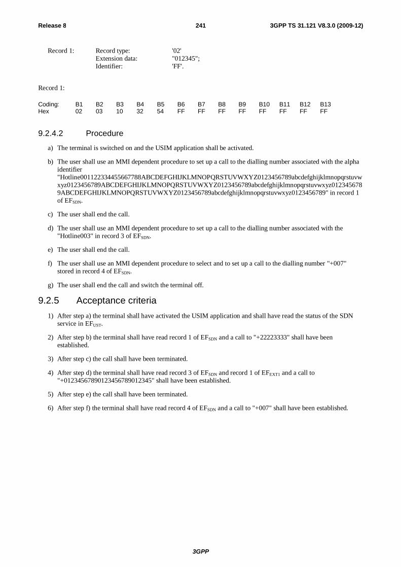
3GPP
Release 8 241 3GPP TS 31.121 V8.3.0 (2009-12)
Record 1: Record type: '02' Extension data: "012345"; Identifier: 'FF'.
Record 1:
Coding: B1 B2 B3 B4 B5 B6 B7 B8 B9 B10 B11 B12 B13 Hex 02 03 10 32 54 FF FF FF FF FF FF FF FF
9.2.4.2 Procedure
a) The terminal is switched on and the USIM application shall be activated.
b) The user shall use an MMI dependent procedure to set up a call to the dialling number associated with the alpha identifier "Hotline001122334455667788ABCDEFGHIJKLMNOPQRSTUVWXYZ0123456789abcdefghijklmnopqrstuvwxyz0123456789ABCDEFGHIJKLMNOPQRSTUVWXYZ0123456789abcdefghijklmnopqrstuvwxyz0123456789ABCDEFGHIJKLMNOPQRSTUVWXYZ0123456789abcdefghijklmnopqrstuvwxyz0123456789" in record 1 of EFSDN.
c) The user shall end the call.
d) The user shall use an MMI dependent procedure to set up a call to the dialling number associated with the "Hotline003" in record 3 of EFSDN.
e) The user shall end the call.
f) The user shall use an MMI dependent procedure to select and to set up a call to the dialling number "+007" stored in record 4 of EFSDN.
g) The user shall end the call and switch the terminal off.
9.2.5 Acceptance criteria 1) After step a) the terminal shall have activated the USIM application and shall have read the status of the SDN
service in EFUST.
2) After step b) the terminal shall have read record 1 of EFSDN and a call to "+22223333" shall have been established.
3) After step c) the call shall have been terminated.
4) After step d) the terminal shall have read record 3 of EFSDN and record 1 of EFEXT1 and a call to "+01234567890123456789012345" shall have been established.
5) After step e) the call shall have been terminated.
6) After step f) the terminal shall have read record 4 of EFSDN and a call to "+007" shall have been established.
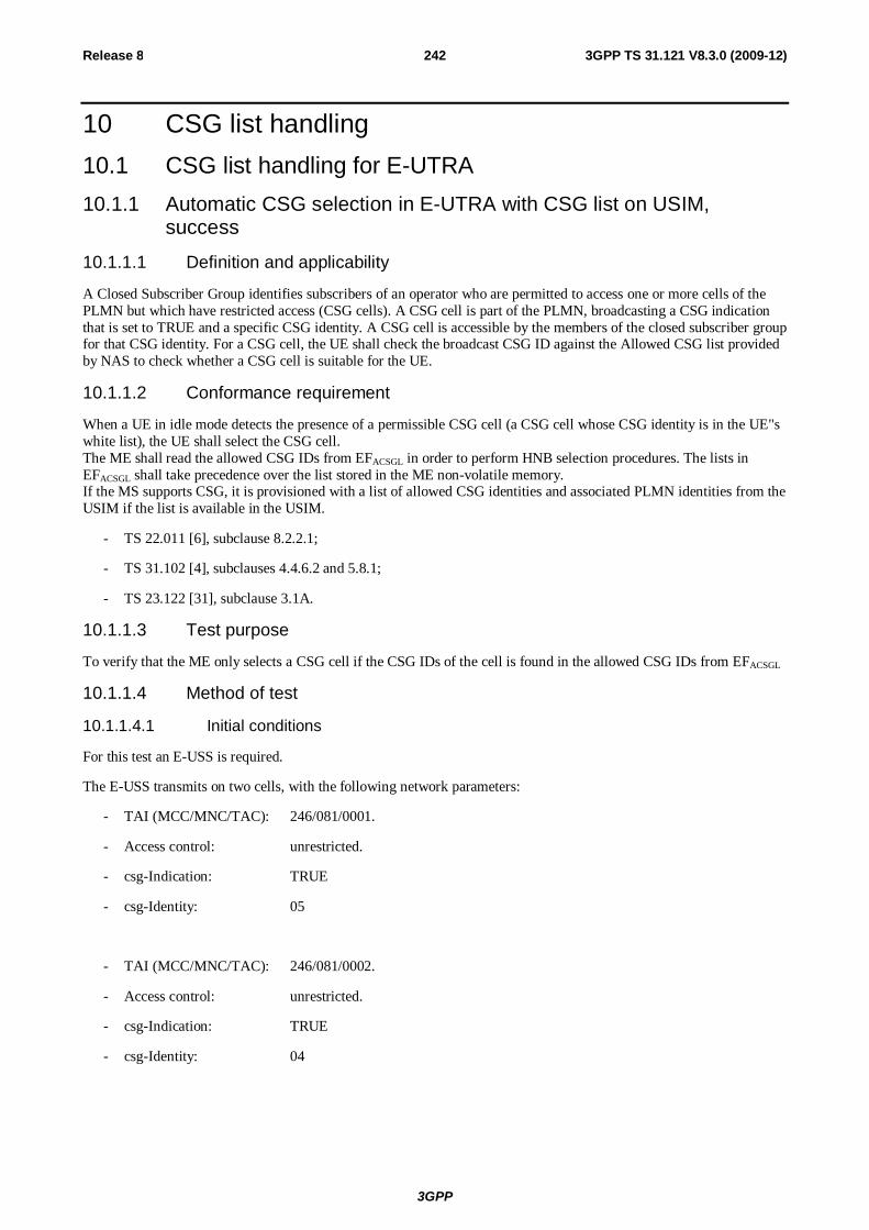
3GPP
Release 8 242 3GPP TS 31.121 V8.3.0 (2009-12)
10 CSG list handling 10.1 CSG list handling for E-UTRA 10.1.1 Automatic CSG selection in E-UTRA with CSG list on USIM,
success
10.1.1.1 Definition and applicability
A Closed Subscriber Group identifies subscribers of an operator who are permitted to access one or more cells of the PLMN but which have restricted access (CSG cells). A CSG cell is part of the PLMN, broadcasting a CSG indication that is set to TRUE and a specific CSG identity. A CSG cell is accessible by the members of the closed subscriber group for that CSG identity. For a CSG cell, the UE shall check the broadcast CSG ID against the Allowed CSG list provided by NAS to check whether a CSG cell is suitable for the UE.
10.1.1.2 Conformance requirement
When a UE in idle mode detects the presence of a permissible CSG cell (a CSG cell whose CSG identity is in the UE"s white list), the UE shall select the CSG cell. The ME shall read the allowed CSG IDs from EFACSGL in order to perform HNB selection procedures. The lists in EFACSGL shall take precedence over the list stored in the ME non-volatile memory. If the MS supports CSG, it is provisioned with a list of allowed CSG identities and associated PLMN identities from the USIM if the list is available in the USIM.
- TS 22.011 [6], subclause 8.2.2.1;
- TS 31.102 [4], subclauses 4.4.6.2 and 5.8.1;
- TS 23.122 [31], subclause 3.1A.
10.1.1.3 Test purpose
To verify that the ME only selects a CSG cell if the CSG IDs of the cell is found in the allowed CSG IDs from EFACSGL
10.1.1.4 Method of test
10.1.1.4.1 Initial conditions
For this test an E-USS is required.
The E-USS transmits on two cells, with the following network parameters:
- TAI (MCC/MNC/TAC): 246/081/0001.
- Access control: unrestricted.
- csg-Indication: TRUE
- csg-Identity: 05
- TAI (MCC/MNC/TAC): 246/081/0002.
- Access control: unrestricted.
- csg-Indication: TRUE
- csg-Identity: 04
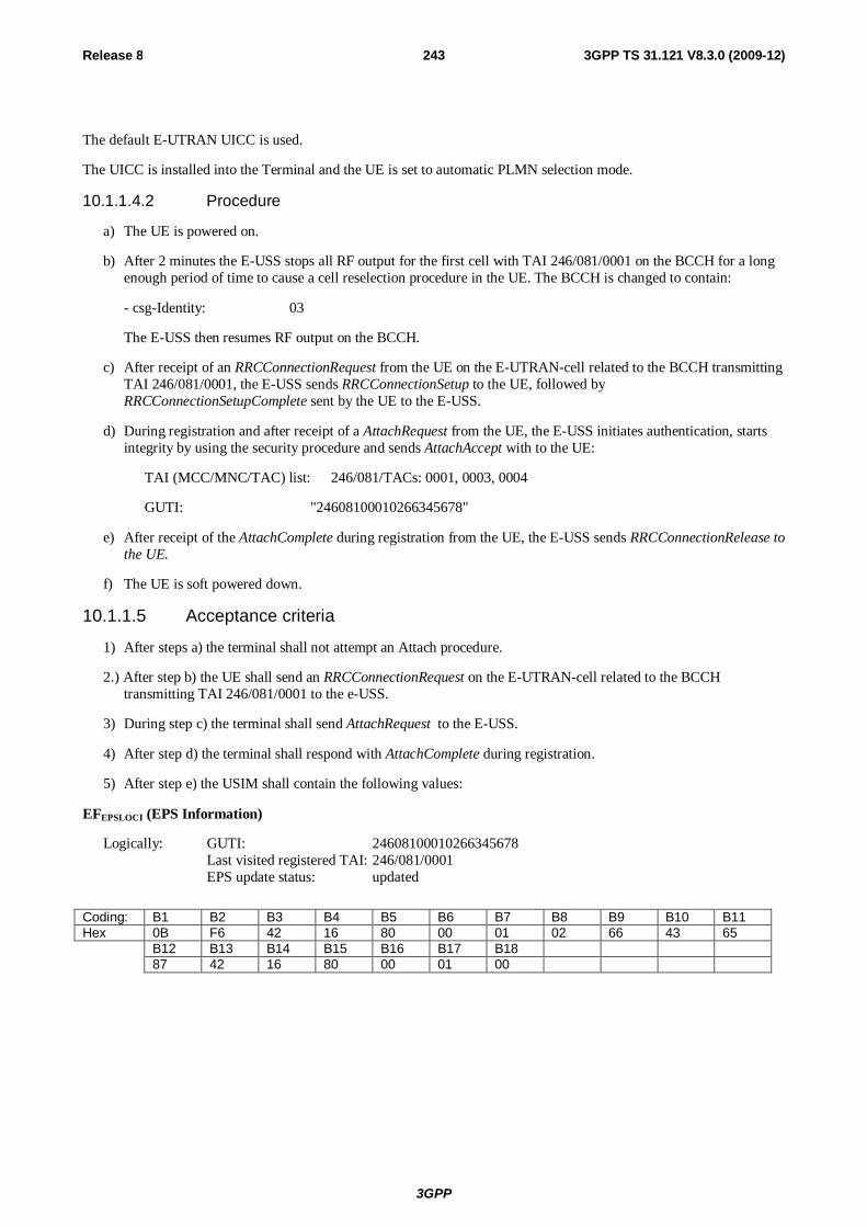
3GPP
Release 8 243 3GPP TS 31.121 V8.3.0 (2009-12)
The default E-UTRAN UICC is used.
The UICC is installed into the Terminal and the UE is set to automatic PLMN selection mode.
10.1.1.4.2 Procedure
a) The UE is powered on.
b) After 2 minutes the E-USS stops all RF output for the first cell with TAI 246/081/0001 on the BCCH for a long enough period of time to cause a cell reselection procedure in the UE. The BCCH is changed to contain:
- csg-Identity: 03
The E-USS then resumes RF output on the BCCH.
c) After receipt of an RRCConnectionRequest from the UE on the E-UTRAN-cell related to the BCCH transmitting TAI 246/081/0001, the E-USS sends RRCConnectionSetup to the UE, followed by RRCConnectionSetupComplete sent by the UE to the E-USS.
d) During registration and after receipt of a AttachRequest from the UE, the E-USS initiates authentication, starts integrity by using the security procedure and sends AttachAccept with to the UE:
TAI (MCC/MNC/TAC) list: 246/081/TACs: 0001, 0003, 0004
GUTI: "24608100010266345678"
e) After receipt of the AttachComplete during registration from the UE, the E-USS sends RRCConnectionRelease to the UE.
f) The UE is soft powered down.
10.1.1.5 Acceptance criteria
1) After steps a) the terminal shall not attempt an Attach procedure.
2.) After step b) the UE shall send an RRCConnectionRequest on the E-UTRAN-cell related to the BCCH transmitting TAI 246/081/0001 to the e-USS.
3) During step c) the terminal shall send AttachRequest to the E-USS.
4) After step d) the terminal shall respond with AttachComplete during registration.
5) After step e) the USIM shall contain the following values:
EFEPSLOCI (EPS Information)
Logically: GUTI: 24608100010266345678 Last visited registered TAI: 246/081/0001 EPS update status: updated
Coding: B1 B2 B3 B4 B5 B6 B7 B8 B9 B10 B11 Hex 0B F6 42 16 80 00 01 02 66 43 65 B12 B13 B14 B15 B16 B17 B18 87 42 16 80 00 01 00
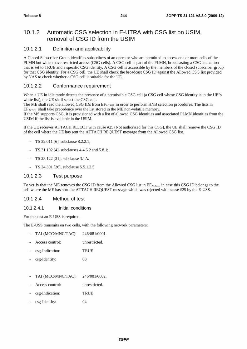
3GPP
Release 8 244 3GPP TS 31.121 V8.3.0 (2009-12)
10.1.2 Automatic CSG selection in E-UTRA with CSG list on USIM, removal of CSG ID from the USIM
10.1.2.1 Definition and applicability
A Closed Subscriber Group identifies subscribers of an operator who are permitted to access one or more cells of the PLMN but which have restricted access (CSG cells). A CSG cell is part of the PLMN, broadcasting a CSG indication that is set to TRUE and a specific CSG identity. A CSG cell is accessible by the members of the closed subscriber group for that CSG identity. For a CSG cell, the UE shall check the broadcast CSG ID against the Allowed CSG list provided by NAS to check whether a CSG cell is suitable for the UE.
10.1.2.2 Conformance requirement
When a UE in idle mode detects the presence of a permissible CSG cell (a CSG cell whose CSG identity is in the UE"s white list), the UE shall select the CSG cell. The ME shall read the allowed CSG IDs from EFACSGL in order to perform HNB selection procedures. The lists in EFACSGL shall take precedence over the list stored in the ME non-volatile memory. If the MS supports CSG, it is provisioned with a list of allowed CSG identities and associated PLMN identities from the USIM if the list is available in the USIM.
If the UE receives ATTACH REJECT with cause #25 (Not authorized for this CSG), the UE shall remove the CSG ID of the cell where the UE has sent the ATTACH REQUEST message from the Allowed CSG list.
- TS 22.011 [6], subclause 8.2.2.1;
- TS 31.102 [4], subclauses 4.4.6.2 and 5.8.1;
- TS 23.122 [31], subclause 3.1A.
- TS 24.301 [26], subclause 5.5.1.2.5
10.1.2.3 Test purpose
To verify that the ME removes the CSG ID from the Allowed CSG list in EFACSGL in case this CSG ID belongs to the cell where the ME has sent the ATTACH REQUEST message which was rejected with cause #25 by the E-USS.
10.1.2.4 Method of test
10.1.2.4.1 Initial conditions
For this test an E-USS is required.
The E-USS transmits on two cells, with the following network parameters:
- TAI (MCC/MNC/TAC): 246/081/0001.
- Access control: unrestricted.
- csg-Indication: TRUE
- csg-Identity: 03
- TAI (MCC/MNC/TAC): 246/081/0002.
- Access control: unrestricted.
- csg-Indication: TRUE
- csg-Identity: 04
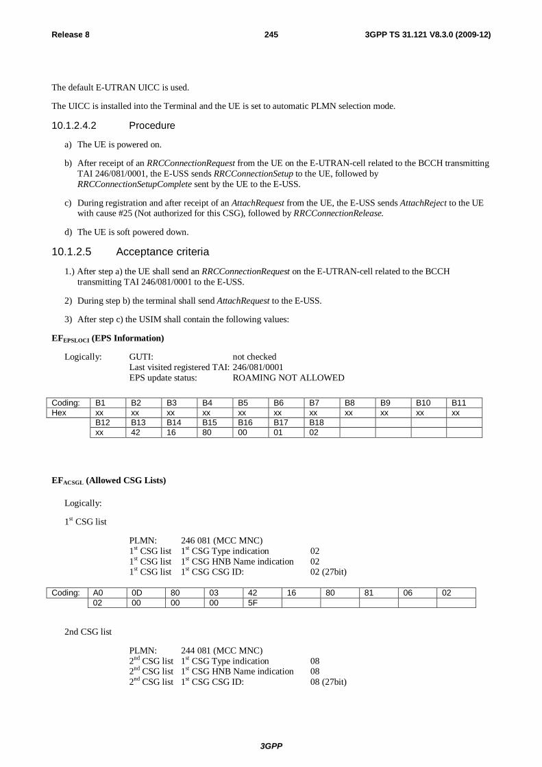
3GPP
Release 8 245 3GPP TS 31.121 V8.3.0 (2009-12)
The default E-UTRAN UICC is used.
The UICC is installed into the Terminal and the UE is set to automatic PLMN selection mode.
10.1.2.4.2 Procedure
a) The UE is powered on.
b) After receipt of an RRCConnectionRequest from the UE on the E-UTRAN-cell related to the BCCH transmitting TAI 246/081/0001, the E-USS sends RRCConnectionSetup to the UE, followed by RRCConnectionSetupComplete sent by the UE to the E-USS.
c) During registration and after receipt of an AttachRequest from the UE, the E-USS sends AttachReject to the UE with cause #25 (Not authorized for this CSG), followed by RRCConnectionRelease.
d) The UE is soft powered down.
10.1.2.5 Acceptance criteria
1.) After step a) the UE shall send an RRCConnectionRequest on the E-UTRAN-cell related to the BCCH transmitting TAI 246/081/0001 to the E-USS.
2) During step b) the terminal shall send AttachRequest to the E-USS.
3) After step c) the USIM shall contain the following values:
EFEPSLOCI (EPS Information)
Logically: GUTI: not checked Last visited registered TAI: 246/081/0001 EPS update status: ROAMING NOT ALLOWED
Coding: B1 B2 B3 B4 B5 B6 B7 B8 B9 B10 B11 Hex xx xx xx xx xx xx xx xx xx xx xx B12 B13 B14 B15 B16 B17 B18 xx 42 16 80 00 01 02
EFACSGL (Allowed CSG Lists)
Logically:
1st CSG list
PLMN: 246 081 (MCC MNC) 1st CSG list 1st CSG Type indication 02 1st CSG list 1st CSG HNB Name indication 02 1st CSG list 1st CSG CSG ID: 02 (27bit)
Coding: A0 0D 80 03 42 16 80 81 06 02 02 00 00 00 5F
2nd CSG list
PLMN: 244 081 (MCC MNC) 2nd CSG list 1st CSG Type indication 08 2nd CSG list 1st CSG HNB Name indication 08 2nd CSG list 1st CSG CSG ID: 08 (27bit)
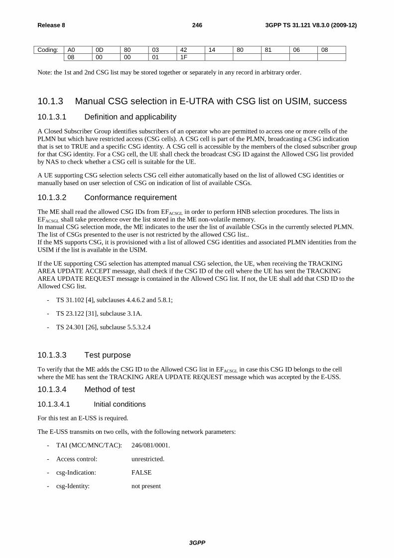
3GPP
Release 8 246 3GPP TS 31.121 V8.3.0 (2009-12)
Coding: A0 0D 80 03 42 14 80 81 06 08 08 00 00 01 1F
Note: the 1st and 2nd CSG list may be stored together or separately in any record in arbitrary order.
10.1.3 Manual CSG selection in E-UTRA with CSG list on USIM, success 10.1.3.1 Definition and applicability
A Closed Subscriber Group identifies subscribers of an operator who are permitted to access one or more cells of the PLMN but which have restricted access (CSG cells). A CSG cell is part of the PLMN, broadcasting a CSG indication that is set to TRUE and a specific CSG identity. A CSG cell is accessible by the members of the closed subscriber group for that CSG identity. For a CSG cell, the UE shall check the broadcast CSG ID against the Allowed CSG list provided by NAS to check whether a CSG cell is suitable for the UE.
A UE supporting CSG selection selects CSG cell either automatically based on the list of allowed CSG identities or manually based on user selection of CSG on indication of list of available CSGs.
10.1.3.2 Conformance requirement
The ME shall read the allowed CSG IDs from EFACSGL in order to perform HNB selection procedures. The lists in EFACSGL shall take precedence over the list stored in the ME non-volatile memory. In manual CSG selection mode, the ME indicates to the user the list of available CSGs in the currently selected PLMN. The list of CSGs presented to the user is not restricted by the allowed CSG list.. If the MS supports CSG, it is provisioned with a list of allowed CSG identities and associated PLMN identities from the USIM if the list is available in the USIM.
If the UE supporting CSG selection has attempted manual CSG selection, the UE, when receiving the TRACKING AREA UPDATE ACCEPT message, shall check if the CSG ID of the cell where the UE has sent the TRACKING AREA UPDATE REQUEST message is contained in the Allowed CSG list. If not, the UE shall add that CSD ID to the Allowed CSG list.
- TS 31.102 [4], subclauses 4.4.6.2 and 5.8.1;
- TS 23.122 [31], subclause 3.1A.
- TS 24.301 [26], subclause 5.5.3.2.4
10.1.3.3 Test purpose
To verify that the ME adds the CSG ID to the Allowed CSG list in EFACSGL in case this CSG ID belongs to the cell where the ME has sent the TRACKING AREA UPDATE REQUEST message which was accepted by the E-USS.
10.1.3.4 Method of test
10.1.3.4.1 Initial conditions
For this test an E-USS is required.
The E-USS transmits on two cells, with the following network parameters:
- TAI (MCC/MNC/TAC): 246/081/0001.
- Access control: unrestricted.
- csg-Indication: FALSE
- csg-Identity: not present
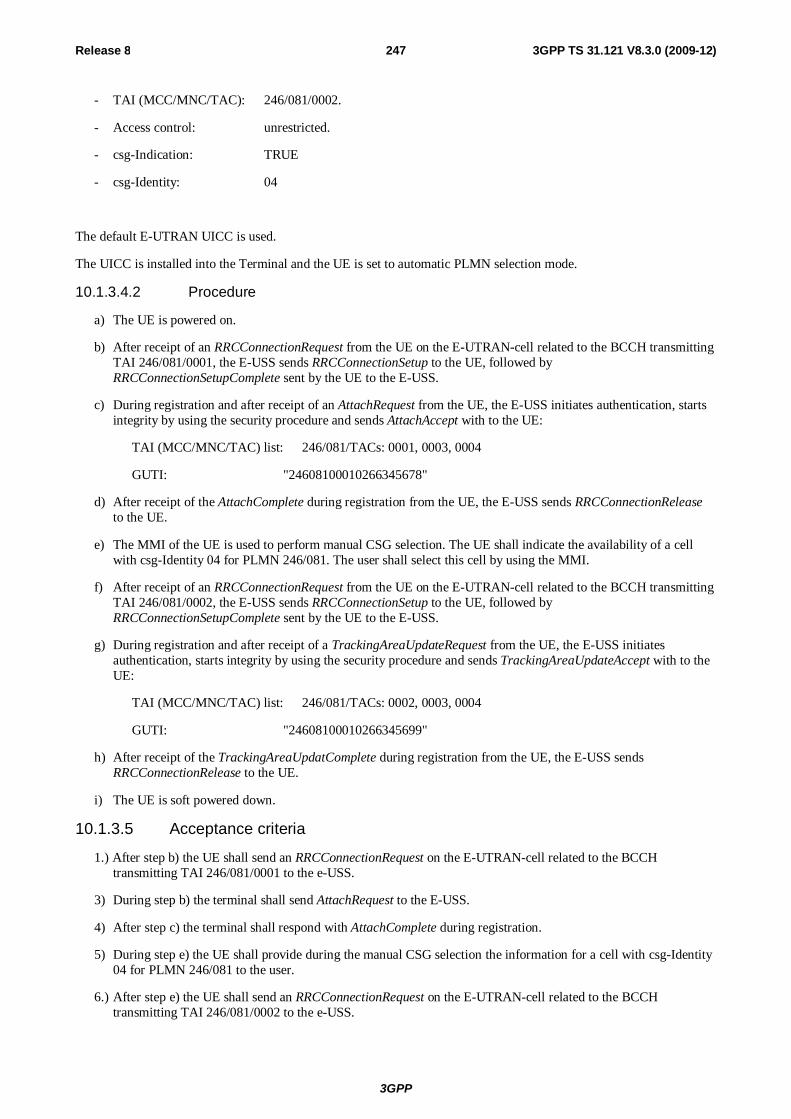
3GPP
Release 8 247 3GPP TS 31.121 V8.3.0 (2009-12)
- TAI (MCC/MNC/TAC): 246/081/0002.
- Access control: unrestricted.
- csg-Indication: TRUE
- csg-Identity: 04
The default E-UTRAN UICC is used.
The UICC is installed into the Terminal and the UE is set to automatic PLMN selection mode.
10.1.3.4.2 Procedure
a) The UE is powered on.
b) After receipt of an RRCConnectionRequest from the UE on the E-UTRAN-cell related to the BCCH transmitting TAI 246/081/0001, the E-USS sends RRCConnectionSetup to the UE, followed by RRCConnectionSetupComplete sent by the UE to the E-USS.
c) During registration and after receipt of an AttachRequest from the UE, the E-USS initiates authentication, starts integrity by using the security procedure and sends AttachAccept with to the UE:
TAI (MCC/MNC/TAC) list: 246/081/TACs: 0001, 0003, 0004
GUTI: "24608100010266345678"
d) After receipt of the AttachComplete during registration from the UE, the E-USS sends RRCConnectionRelease to the UE.
e) The MMI of the UE is used to perform manual CSG selection. The UE shall indicate the availability of a cell with csg-Identity 04 for PLMN 246/081. The user shall select this cell by using the MMI.
f) After receipt of an RRCConnectionRequest from the UE on the E-UTRAN-cell related to the BCCH transmitting TAI 246/081/0002, the E-USS sends RRCConnectionSetup to the UE, followed by RRCConnectionSetupComplete sent by the UE to the E-USS.
g) During registration and after receipt of a TrackingAreaUpdateRequest from the UE, the E-USS initiates authentication, starts integrity by using the security procedure and sends TrackingAreaUpdateAccept with to the UE:
TAI (MCC/MNC/TAC) list: 246/081/TACs: 0002, 0003, 0004
GUTI: "24608100010266345699"
h) After receipt of the TrackingAreaUpdatComplete during registration from the UE, the E-USS sends RRCConnectionRelease to the UE.
i) The UE is soft powered down.
10.1.3.5 Acceptance criteria
1.) After step b) the UE shall send an RRCConnectionRequest on the E-UTRAN-cell related to the BCCH transmitting TAI 246/081/0001 to the e-USS.
3) During step b) the terminal shall send AttachRequest to the E-USS.
4) After step c) the terminal shall respond with AttachComplete during registration.
5) During step e) the UE shall provide during the manual CSG selection the information for a cell with csg-Identity 04 for PLMN 246/081 to the user.
6.) After step e) the UE shall send an RRCConnectionRequest on the E-UTRAN-cell related to the BCCH transmitting TAI 246/081/0002 to the e-USS.
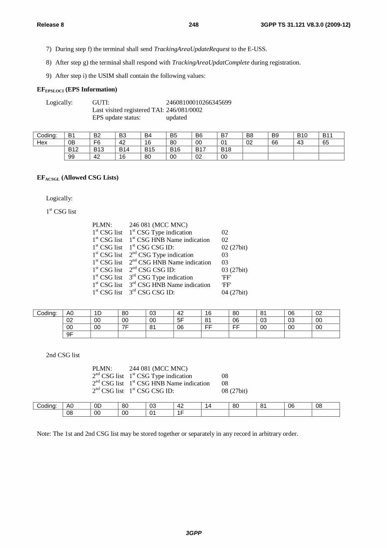
3GPP
Release 8 248 3GPP TS 31.121 V8.3.0 (2009-12)
7) During step f) the terminal shall send TrackingAreaUpdateRequest to the E-USS.
8) After step g) the terminal shall respond with TrackingAreaUpdatComplete during registration.
9) After step i) the USIM shall contain the following values:
EFEPSLOCI (EPS Information)
Logically: GUTI: 24608100010266345699 Last visited registered TAI: 246/081/0002 EPS update status: updated
Coding: B1 B2 B3 B4 B5 B6 B7 B8 B9 B10 B11 Hex 0B F6 42 16 80 00 01 02 66 43 65 B12 B13 B14 B15 B16 B17 B18 99 42 16 80 00 02 00
EFACSGL (Allowed CSG Lists)
Logically:
1st CSG list
PLMN: 246 081 (MCC MNC) 1st CSG list 1st CSG Type indication 02 1st CSG list 1st CSG HNB Name indication 02 1st CSG list 1st CSG CSG ID: 02 (27bit) 1st CSG list 2nd CSG Type indication 03 1st CSG list 2nd CSG HNB Name indication 03 1st CSG list 2nd CSG CSG ID: 03 (27bit) 1st CSG list 3rd CSG Type indication 'FF' 1st CSG list 3rd CSG HNB Name indication 'FF' 1st CSG list 3rd CSG CSG ID: 04 (27bit)
Coding: A0 1D 80 03 42 16 80 81 06 02 02 00 00 00 5F 81 06 03 03 00 00 00 7F 81 06 FF FF 00 00 00 9F
2nd CSG list
PLMN: 244 081 (MCC MNC) 2nd CSG list 1st CSG Type indication 08 2nd CSG list 1st CSG HNB Name indication 08 2nd CSG list 1st CSG CSG ID: 08 (27bit)
Coding: A0 0D 80 03 42 14 80 81 06 08 08 00 00 01 1F
Note: The 1st and 2nd CSG list may be stored together or separately in any record in arbitrary order.

3GPP
Release 8 249 3GPP TS 31.121 V8.3.0 (2009-12)
10.1.4 Manual CSG selection in E-UTRA with CSG list on USIM, rejected
10.1.4.1 Definition and applicability
A Closed Subscriber Group identifies subscribers of an operator who are permitted to access one or more cells of the PLMN but which have restricted access (CSG cells). A CSG cell is part of the PLMN, broadcasting a CSG indication that is set to TRUE and a specific CSG identity. A CSG cell is accessible by the members of the closed subscriber group for that CSG identity. For a CSG cell, the UE shall check the broadcast CSG ID against the Allowed CSG list provided by NAS to check whether a CSG cell is suitable for the UE.
A UE supporting CSG selection selects CSG cell either automatically based on the list of allowed CSG identities or manually based on user selection of CSG on indication of list of available CSGs.
10.1.4.2 Conformance requirement
The ME shall read the allowed CSG IDs from EFACSGL in order to perform HNB selection procedures. The lists in EFACSGL shall take precedence over the list stored in the ME non-volatile memory. In manual CSG selection mode, the ME indicates to the user the list of available CSGs in the currently selected PLMN. The list of CSGs presented to the user is not restricted by the allowed CSG list. If the MS supports CSG, it is provisioned with a list of allowed CSG identities and associated PLMN identities from the USIM if the list is available in the USIM.
If the UE supporting CSG selection has attempted manual CSG selection, the UE, when receiving the TRACKING AREA UPDATE REJECT message with cause #25 (Not authorized for this CSG), shall remove the CSG ID of the cell where the UE has sent the TRACKING AREA UPDATE REQUEST message if the CSG ID is contained in the Allowed CSG list.
- TS 31.102 [4], subclauses 4.4.6.2 and 5.8.1;
- TS 23.122 [31], subclause 3.1A.
- TS 24.301 [26], subclause 5.5.3.2.5
10.1.4.3 Test purpose
To verify that the ME does not add the CSG ID to the Allowed CSG list in EFACSGL in case this CSG ID belongs to the cell where the ME has sent the TRACKING AREA UPDATE REQUEST message which was rejected by the E-USS.
10.1.4.4 Method of test
10.1.4.4.1 Initial conditions
For this test an E-USS is required.
The E-USS transmits on two cells, with the following network parameters:
- TAI (MCC/MNC/TAC): 246/081/0001.
- Access control: unrestricted.
- csg-Indication: FALSE
- csg-Identity: not present
- TAI (MCC/MNC/TAC): 246/081/0002.
- Access control: unrestricted.
- csg-Indication: TRUE
- csg-Identity: 04
3GPP
Release 8 250 3GPP TS 31.121 V8.3.0 (2009-12)
The default E-UTRAN UICC is used.
The UICC is installed into the Terminal and the UE is set to automatic PLMN selection mode.
10.1.4.4.2 Procedure
a) The UE is powered on.
b) After receipt of an RRCConnectionRequest from the UE on the E-UTRAN-cell related to the BCCH transmitting TAI 246/081/0001, the E-USS sends RRCConnectionSetup to the UE, followed by RRCConnectionSetupComplete sent by the UE to the E-USS.
c) During registration and after receipt of a AttachRequest from the UE, the E-USS initiates authentication, starts integrity by using the security procedure and sends AttachAccept with to the UE:
TAI (MCC/MNC/TAC) list: 246/081/TACs: 0001, 0003, 0004
GUTI: "24608100010266345678"
d) After receipt of the AttachComplete during registration from the UE, the E-USS sends RRCConnectionRelease, to the UE.
e) The MMI of the UE is used to perform manual CSG selection. The UE shall indicate the availability of a cell with csg-Identity 04 for PLMN 246/081. The user shall select this cell by using the MMI.
f) After receipt of an RRCConnectionRequest from the UE on the E-UTRAN-cell related to the BCCH transmitting TAI 246/081/0002, the E-USS sends RRCConnectionSetup to the UE, followed by RRCConnectionSetupComplete sent by the UE to the E-USS.
g) During registration and after receipt of an TrackingAreaUpdateRequest from the UE, the E-USS sends TrackingAreaUpdateReject to the UE with cause #25 (Not authorized for this CSG), followed by RRCConnectionRelease to the UE.
h) The UE is soft powered down.
10.1.4.5 Acceptance criteria
1.) After step b) the UE shall send an RRCConnectionRequest on the E-UTRAN-cell related to the BCCH transmitting TAI 246/081/0001 to the e-USS.
3) During step b) the terminal shall send AttachRequest to the E-USS.
4) After step c) the terminal shall respond with AttachComplete during registration.
5.) During step e) the UE shall provide during the manual CSG selection the information for a cell with csg-Identity 04 for PLMN 246/081 to the user.
6.) After step e) the UE shall send a RRCConnectionRequest on the E-UTRAN-cell related to the BCCH transmitting TAI 246/081/0002 to the e-USS.
7) During step f) the terminal shall send TrackingAreaUpdateRequest to the E-USS.
8) After step h) the USIM shall contain the following values:
EFEPSLOCI (EPS Information)
Logically: GUTI: not checked Last visited registered TAI: 246/081/0001 EPS update status: ROAMING NOT ALLOWED
3GPP
Release 8 251 3GPP TS 31.121 V8.3.0 (2009-12)
Coding: B1 B2 B3 B4 B5 B6 B7 B8 B9 B10 B11 Hex xx xx xx xx xx xx xx xx xx xx xx B12 B13 B14 B15 B16 B17 B18 xx 42 16 80 00 01 02
EFACSGL (Allowed CSG Lists)
Content not changed, shall be the same as defined in clause 4.4.5.
10.1.5 CSG selection in E-UTRA with no CSG list on USIM, no IMSI change
10.1.5.1 Definition and applicability
A Closed Subscriber Group identifies subscribers of an operator who are permitted to access one or more cells of the PLMN but which have restricted access (CSG cells). A CSG cell is part of the PLMN, broadcasting a CSG indication that is set to TRUE and a specific CSG identity. A CSG cell is accessible by the members of the closed subscriber group for that CSG identity. For a CSG cell, the UE shall check the broadcast CSG ID against the Allowed CSG list provided by NAS to check whether a CSG cell is suitable for the UE.
A UE supporting CSG selection selects CSG cell either automatically based on the list of allowed CSG identities or manually based on user selection of CSG on indication of list of available CSGs.
10.1.5.2 Conformance requirement
In manual CSG selection mode, the ME indicates to the user the list of available CSGs in the currently selected PLMN. The list of CSGs presented to the user is not restricted by the allowed CSG list.. If the MS supports CSG, it is provisioned with a list of allowed CSG identities and associated PLMN identities from the USIM if the list is available in the USIM.
If the UE supporting CSG selection has attempted manual CSG selection, the UE, when receiving the TRACKING AREA UPDATE ACCEPT message, shall check if the CSG ID of the cell where the UE has sent the TRACKING AREA UPDATE REQUEST message is contained in the Allowed CSG list. If not, the UE shall add that CSD ID to the Allowed CSG list.
If the corresponding file is not present on the USIM, these EMM parameters except allowed CSG list are stored in a non-volatile memory in the ME together with the IMSI from the USIM. The allowed CSG list is stored in a non-volatile memory in the ME if the UE supports CSG selection. These EMM parameters can only be used if the IMSI from the USIM matches the IMSI stored in the non-volatile memory; else the UE shall delete the EMM parameters.
- TS 31.102 [4], subclauses 4.4.6.2 and 5.8.1;
- TS 23.122 [31], subclause 3.1A.
- TS 24.301 [26], subclause 5.5.3.2.4 and Annex C.
10.1.5.3 Test purpose
To verify that the ME adds the CSG ID to the Allowed CSG list in a non-volatile memory in the ME together with the IMSI from the USIM in case this CSG ID belongs to the cell where the ME has sent the TRACKING AREA UPDATE REQUEST message which was accepted by the E-USS as the corresponding file is not present on the simulated USIM. To verify that the ME still has this CSG ID stored in the Allowed CSG list available together with the IMSI after powered down and up in case the IMSI of the USIM has not changed.
3GPP
Release 8 252 3GPP TS 31.121 V8.3.0 (2009-12)
To verify that the ME removes the CSG ID from the Allowed CSG list inside the terminal in case this CSG ID belongs to the cell where the ME has sent the ATTACH REQUEST message which was rejected with cause #25 by the E-USS.
10.1.5.4 Method of test
10.1.5.4.1 Initial conditions
For this test an E-USS is required.
The E-USS transmits on two cells, with the following network parameters:
- TAI (MCC/MNC/TAC): 246/081/0001.
- Access control: unrestricted.
- csg-Indication: FALSE
- csg-Identity: not present
- TAI (MCC/MNC/TAC): 246/081/0002.
- Access control: unrestricted.
- csg-Indication: TRUE
- csg-Identity: 04
The default UICC (without the service "Allowed CSG Lists and corresponding indications") is installed into the Terminal.
The ME shall not have csg-ID = 04 in the allowed CSG list stored in a non-volatile memory in the ME and the ME is set to automatic PLMN selection mode.
10.1.5.4.2 Procedure
a) The UE is powered on.
b) After receipt of an RRCConnectionRequest from the UE on the E-UTRAN-cell related to the BCCH transmitting TAI 246/081/0001, the E-USS sends RRCConnectionSetup to the UE, followed by RRCConnectionSetupComplete sent by the UE to the E-USS.
c) During registration and after receipt of an AttachRequest from the UE, the E-USS initiates authentication, starts integrity by using the security procedure and sends AttachAccept with the following parameters to the UE:
TAI (MCC/MNC/TAC) list: 246/081/TACs: 0001, 0003, 0004
GUTI: "24608100010266345678"
d) After receipt of the AttachComplete during registration from the UE, the E-USS sends RRCConnectionRelease to the UE.
e) The MMI of the UE is used to perform manual CSG selection. The UE shall indicate the availability of a cell with csg-Identity 04 for PLMN 246/081. The user shall select this cell by using the MMI.
f) After receipt of an RRCConnectionRequest from the UE on the E-UTRAN-cell related to the BCCH transmitting TAI 246/081/0002, the E-USS sends RRCConnectionSetup to the UE, followed by RRCConnectionSetupComplete sent by the UE to the E-USS.
3GPP
Release 8 253 3GPP TS 31.121 V8.3.0 (2009-12)
g) During registration and after receipt of a TrackingAreaUpdateRequest from the UE, the E-USS initiates authentication, starts integrity by using the security procedure and sends TrackingAreaUpdateAccept with the following parameters to the UE:
TAI (MCC/MNC/TAC) list: 246/081/TACs: 0002, 0003, 0004
GUTI: "24608100010266345699"
h) After receipt of the TrackingAreaUpdateComplete during registration from the UE, the E-USS sends RRCConnectionRelease to the UE.
i) The UE is switched off and performs the Detach procedure.
j) The default UICC remains in use.
k) The E-USS shall change the BCCH for the cell transmitting TAI 246/081/0001 to the following network parameters:
- csg-Indication: TRUE
- csg-Identity: 06
l) The UE is powered on.
m) After receipt of an RRCConnectionRequest from the UE on the E-UTRAN-cell related to the BCCH transmitting TAI 246/081/0002, the E-USS sends RRCConnectionSetup to the UE, followed by RRCConnectionSetupComplete sent by the UE to the E-USS.
n) During registration and after receipt of an AttachRequest from the UE, the E-USS sends AttachReject to the UE with cause #25 (Not authorized for this CSG), followed by RRCConnectionRelease.
o) The UE is soft powered down.
p) The default UICC remains in use.
q) The UE is powered on.
r) After 2 minutes the UE is soft powered down.
10.1.5.5 Acceptance criteria
1.) After step b) the UE shall send an RRCConnectionRequest on the E-UTRAN-cell related to the BCCH transmitting TAI 246/081/0001 to the e-USS.
3) During step b) the terminal shall send AttachRequest to the E-USS.
4) After step c) the terminal shall respond with AttachComplete during registration.
5) During step e) the UE shall provide during the manual CSG selection the information for a cell with csg-Identity 04 for PLMN 246/081 to the user.
6.) After step e) the UE shall send an RRCConnectionRequest on the E-UTRAN-cell related to the BCCH transmitting TAI 246/081/0002 to the e-USS.
7) During step f) the terminal shall send TrackingAreaUpdateRequest to the E-USS.
8) After step g) the terminal shall respond with TrackingAreaUpdateComplete during registration.
9.) After step l) the UE shall send an RRCConnectionRequest on the E-UTRAN-cell related to the BCCH transmitting TAI 246/081/0002 to the e-USS.
10) During step n) the terminal shall send AttachRequest to the E-USS.
11) After step q) the terminal shall not try to register to the E-USS.
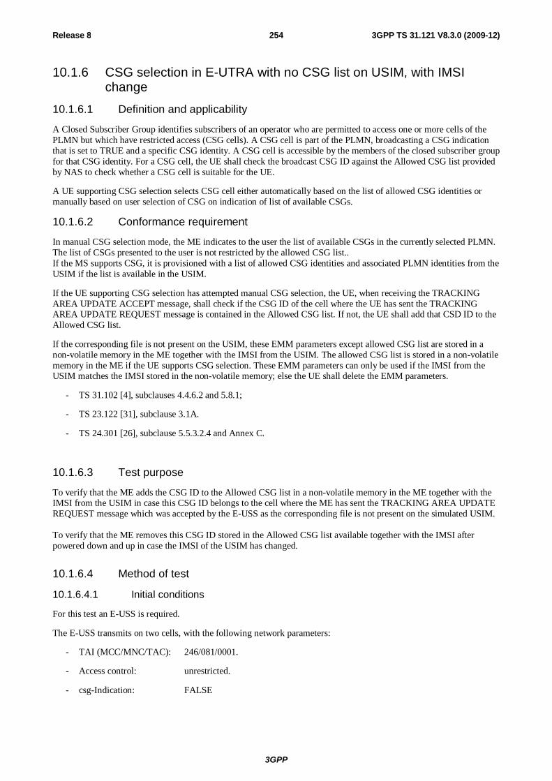
3GPP
Release 8 254 3GPP TS 31.121 V8.3.0 (2009-12)
10.1.6 CSG selection in E-UTRA with no CSG list on USIM, with IMSI change
10.1.6.1 Definition and applicability
A Closed Subscriber Group identifies subscribers of an operator who are permitted to access one or more cells of the PLMN but which have restricted access (CSG cells). A CSG cell is part of the PLMN, broadcasting a CSG indication that is set to TRUE and a specific CSG identity. A CSG cell is accessible by the members of the closed subscriber group for that CSG identity. For a CSG cell, the UE shall check the broadcast CSG ID against the Allowed CSG list provided by NAS to check whether a CSG cell is suitable for the UE.
A UE supporting CSG selection selects CSG cell either automatically based on the list of allowed CSG identities or manually based on user selection of CSG on indication of list of available CSGs.
10.1.6.2 Conformance requirement
In manual CSG selection mode, the ME indicates to the user the list of available CSGs in the currently selected PLMN. The list of CSGs presented to the user is not restricted by the allowed CSG list.. If the MS supports CSG, it is provisioned with a list of allowed CSG identities and associated PLMN identities from the USIM if the list is available in the USIM.
If the UE supporting CSG selection has attempted manual CSG selection, the UE, when receiving the TRACKING AREA UPDATE ACCEPT message, shall check if the CSG ID of the cell where the UE has sent the TRACKING AREA UPDATE REQUEST message is contained in the Allowed CSG list. If not, the UE shall add that CSD ID to the Allowed CSG list.
If the corresponding file is not present on the USIM, these EMM parameters except allowed CSG list are stored in a non-volatile memory in the ME together with the IMSI from the USIM. The allowed CSG list is stored in a non-volatile memory in the ME if the UE supports CSG selection. These EMM parameters can only be used if the IMSI from the USIM matches the IMSI stored in the non-volatile memory; else the UE shall delete the EMM parameters.
- TS 31.102 [4], subclauses 4.4.6.2 and 5.8.1;
- TS 23.122 [31], subclause 3.1A.
- TS 24.301 [26], subclause 5.5.3.2.4 and Annex C.
10.1.6.3 Test purpose
To verify that the ME adds the CSG ID to the Allowed CSG list in a non-volatile memory in the ME together with the IMSI from the USIM in case this CSG ID belongs to the cell where the ME has sent the TRACKING AREA UPDATE REQUEST message which was accepted by the E-USS as the corresponding file is not present on the simulated USIM. To verify that the ME removes this CSG ID stored in the Allowed CSG list available together with the IMSI after powered down and up in case the IMSI of the USIM has changed.
10.1.6.4 Method of test
10.1.6.4.1 Initial conditions
For this test an E-USS is required.
The E-USS transmits on two cells, with the following network parameters:
- TAI (MCC/MNC/TAC): 246/081/0001.
- Access control: unrestricted.
- csg-Indication: FALSE
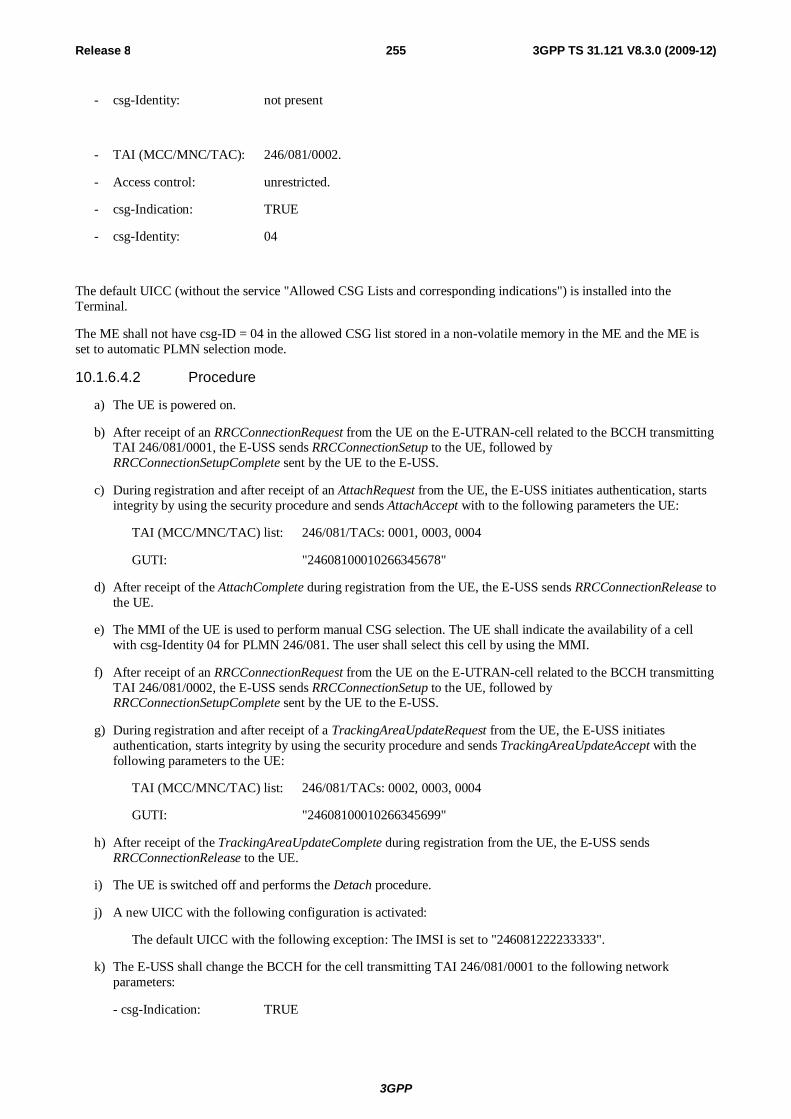
3GPP
Release 8 255 3GPP TS 31.121 V8.3.0 (2009-12)
- csg-Identity: not present
- TAI (MCC/MNC/TAC): 246/081/0002.
- Access control: unrestricted.
- csg-Indication: TRUE
- csg-Identity: 04
The default UICC (without the service "Allowed CSG Lists and corresponding indications") is installed into the Terminal.
The ME shall not have csg-ID = 04 in the allowed CSG list stored in a non-volatile memory in the ME and the ME is set to automatic PLMN selection mode.
10.1.6.4.2 Procedure
a) The UE is powered on.
b) After receipt of an RRCConnectionRequest from the UE on the E-UTRAN-cell related to the BCCH transmitting TAI 246/081/0001, the E-USS sends RRCConnectionSetup to the UE, followed by RRCConnectionSetupComplete sent by the UE to the E-USS.
c) During registration and after receipt of an AttachRequest from the UE, the E-USS initiates authentication, starts integrity by using the security procedure and sends AttachAccept with to the following parameters the UE:
TAI (MCC/MNC/TAC) list: 246/081/TACs: 0001, 0003, 0004
GUTI: "24608100010266345678"
d) After receipt of the AttachComplete during registration from the UE, the E-USS sends RRCConnectionRelease to the UE.
e) The MMI of the UE is used to perform manual CSG selection. The UE shall indicate the availability of a cell with csg-Identity 04 for PLMN 246/081. The user shall select this cell by using the MMI.
f) After receipt of an RRCConnectionRequest from the UE on the E-UTRAN-cell related to the BCCH transmitting TAI 246/081/0002, the E-USS sends RRCConnectionSetup to the UE, followed by RRCConnectionSetupComplete sent by the UE to the E-USS.
g) During registration and after receipt of a TrackingAreaUpdateRequest from the UE, the E-USS initiates authentication, starts integrity by using the security procedure and sends TrackingAreaUpdateAccept with the following parameters to the UE:
TAI (MCC/MNC/TAC) list: 246/081/TACs: 0002, 0003, 0004
GUTI: "24608100010266345699"
h) After receipt of the TrackingAreaUpdateComplete during registration from the UE, the E-USS sends RRCConnectionRelease to the UE.
i) The UE is switched off and performs the Detach procedure.
j) A new UICC with the following configuration is activated:
The default UICC with the following exception: The IMSI is set to "246081222233333".
k) The E-USS shall change the BCCH for the cell transmitting TAI 246/081/0001 to the following network parameters:
- csg-Indication: TRUE
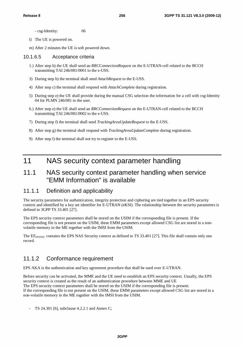
3GPP
Release 8 256 3GPP TS 31.121 V8.3.0 (2009-12)
- csg-Identity: 06
l) The UE is powered on.
m) After 2 minutes the UE is soft powered down.
10.1.6.5 Acceptance criteria
1.) After step b) the UE shall send an RRCConnectionRequest on the E-UTRAN-cell related to the BCCH transmitting TAI 246/081/0001 to the e-USS.
3) During step b) the terminal shall send AttachRequest to the E-USS.
4) After step c) the terminal shall respond with AttachComplete during registration.
5) During step e) the UE shall provide during the manual CSG selection the information for a cell with csg-Identity 04 for PLMN 246/081 to the user.
6.) After step e) the UE shall send an RRCConnectionRequest on the E-UTRAN-cell related to the BCCH transmitting TAI 246/081/0002 to the e-USS.
7) During step f) the terminal shall send TrackingAreaUpdateRequest to the E-USS.
8) After step g) the terminal shall respond with TrackingAreaUpdateComplete during registration.
9) After step l) the terminal shall not try to register to the E-USS.
11 NAS security context parameter handling 11.1 NAS security context parameter handling when service
"EMM Information" is available 11.1.1 Definition and applicability The security parameters for authentication, integrity protection and ciphering are tied together in an EPS security context and identified by a key set identifier for E-UTRAN (eKSI). The relationship between the security parameters is defined in 3GPP TS 33.401 [27].
The EPS security context parameters shall be stored on the USIM if the corresponding file is present. If the corresponding file is not present on the USIM, these EMM parameters except allowed CSG list are stored in a non-volatile memory in the ME together with the IMSI from the USIM.
The EFEPSNSC contains the EPS NAS Security context as defined in TS 33.401 [27]. This file shall contain only one record.
11.1.2 Conformance requirement EPS AKA is the authentication and key agreement procedure that shall be used over E-UTRAN.
Before security can be activated, the MME and the UE need to establish an EPS security context. Usually, the EPS security context is created as the result of an authentication procedure between MME and UE The EPS security context parameters shall be stored on the USIM if the corresponding file is present. If the corresponding file is not present on the USIM, these EMM parameters except allowed CSG list are stored in a non-volatile memory in the ME together with the IMSI from the USIM.
- TS 24.301 [6], subclause 4.2.2.1 and Annex C;
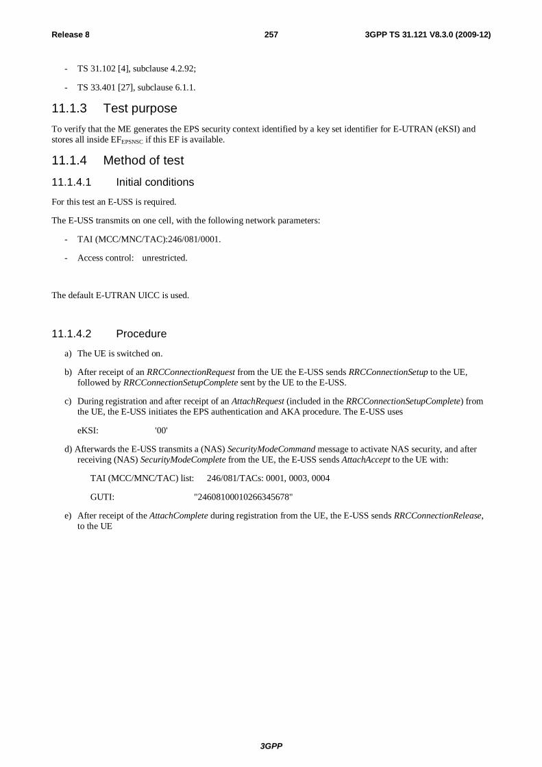
3GPP
Release 8 257 3GPP TS 31.121 V8.3.0 (2009-12)
- TS 31.102 [4], subclause 4.2.92;
- TS 33.401 [27], subclause 6.1.1.
11.1.3 Test purpose To verify that the ME generates the EPS security context identified by a key set identifier for E-UTRAN (eKSI) and stores all inside EFEPSNSC if this EF is available.
11.1.4 Method of test
11.1.4.1 Initial conditions
For this test an E-USS is required.
The E-USS transmits on one cell, with the following network parameters:
- TAI (MCC/MNC/TAC): 246/081/0001.
- Access control: unrestricted.
The default E-UTRAN UICC is used.
11.1.4.2 Procedure
a) The UE is switched on.
b) After receipt of an RRCConnectionRequest from the UE the E-USS sends RRCConnectionSetup to the UE, followed by RRCConnectionSetupComplete sent by the UE to the E-USS.
c) During registration and after receipt of an AttachRequest (included in the RRCConnectionSetupComplete) from the UE, the E-USS initiates the EPS authentication and AKA procedure. The E-USS uses
eKSI: '00'
d) Afterwards the E-USS transmits a (NAS) SecurityModeCommand message to activate NAS security, and after receiving (NAS) SecurityModeComplete from the UE, the E-USS sends AttachAccept to the UE with:
TAI (MCC/MNC/TAC) list: 246/081/TACs: 0001, 0003, 0004
GUTI: "24608100010266345678"
e) After receipt of the AttachComplete during registration from the UE, the E-USS sends RRCConnectionRelease, to the UE
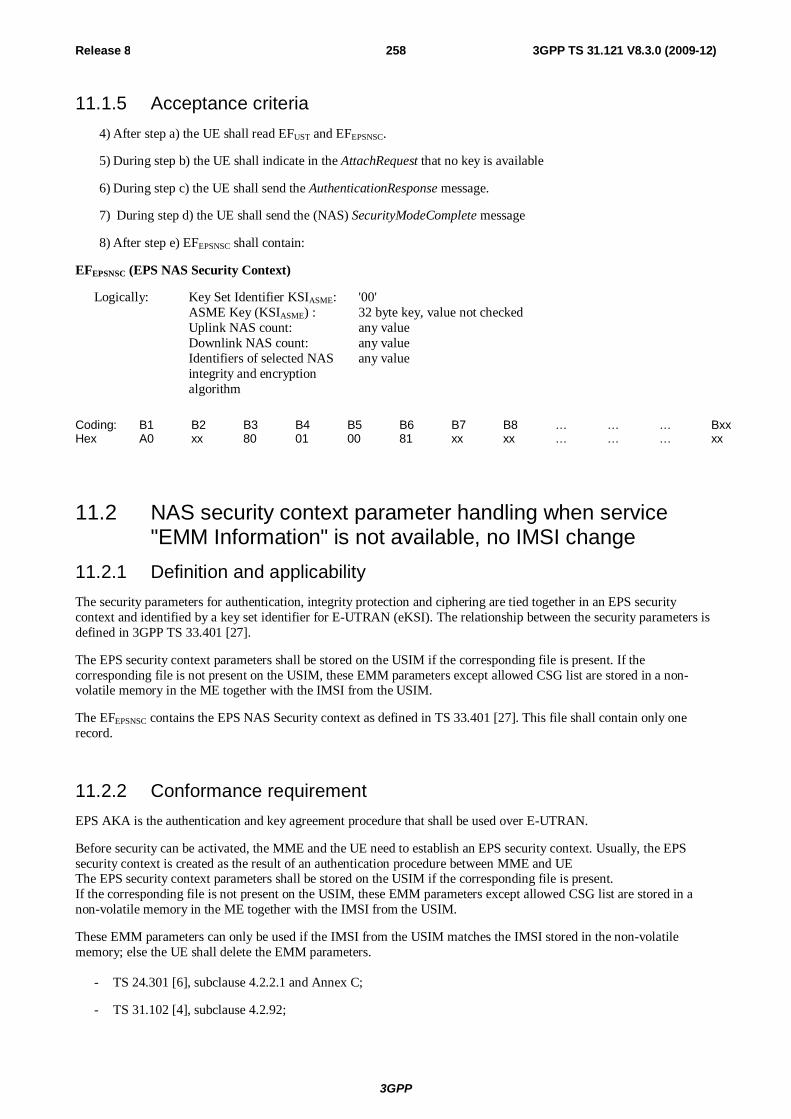
3GPP
Release 8 258 3GPP TS 31.121 V8.3.0 (2009-12)
11.1.5 Acceptance criteria 4) After step a) the UE shall read EFUST and EFEPSNSC.
5) During step b) the UE shall indicate in the AttachRequest that no key is available
6) During step c) the UE shall send the AuthenticationResponse message.
7) During step d) the UE shall send the (NAS) SecurityModeComplete message
8) After step e) EFEPSNSC shall contain:
EFEPSNSC (EPS NAS Security Context)
Logically: Key Set Identifier KSIASME: '00' ASME Key (KSIASME) : 32 byte key, value not checked Uplink NAS count: any value Downlink NAS count: any value Identifiers of selected NAS any value
integrity and encryption algorithm
Coding: B1 B2 B3 B4 B5 B6 B7 B8 … … … Bxx Hex A0 xx 80 01 00 81 xx xx … … … xx
11.2 NAS security context parameter handling when service "EMM Information" is not available, no IMSI change
11.2.1 Definition and applicability The security parameters for authentication, integrity protection and ciphering are tied together in an EPS security context and identified by a key set identifier for E-UTRAN (eKSI). The relationship between the security parameters is defined in 3GPP TS 33.401 [27].
The EPS security context parameters shall be stored on the USIM if the corresponding file is present. If the corresponding file is not present on the USIM, these EMM parameters except allowed CSG list are stored in a non-volatile memory in the ME together with the IMSI from the USIM.
The EFEPSNSC contains the EPS NAS Security context as defined in TS 33.401 [27]. This file shall contain only one record.
11.2.2 Conformance requirement EPS AKA is the authentication and key agreement procedure that shall be used over E-UTRAN.
Before security can be activated, the MME and the UE need to establish an EPS security context. Usually, the EPS security context is created as the result of an authentication procedure between MME and UE The EPS security context parameters shall be stored on the USIM if the corresponding file is present. If the corresponding file is not present on the USIM, these EMM parameters except allowed CSG list are stored in a non-volatile memory in the ME together with the IMSI from the USIM.
These EMM parameters can only be used if the IMSI from the USIM matches the IMSI stored in the non-volatile memory; else the UE shall delete the EMM parameters.
- TS 24.301 [6], subclause 4.2.2.1 and Annex C;
- TS 31.102 [4], subclause 4.2.92;
3GPP
Release 8 259 3GPP TS 31.121 V8.3.0 (2009-12)
- TS 33.401 [27], subclause 6.1.1.
11.2.3 Test purpose To verify that the ME generates the EPS security context identified by a key set identifier for E-UTRAN (eKSI) and stores all inside a non-volatile memory in the ME as EMM information is not available on the USIM. During the test the IMSI on the USIM remains unchanged.
11.2.4 Method of test 11.2.4.1 Initial conditions
For this test an E-USS is required.
The E-USS transmits on one cell, with the following network parameters:
- TAI (MCC/MNC/TAC): 246/081/0001.
- Access control: unrestricted.
The default UICC (without the service "EMM Information") is installed into the Terminal and the UE is powered on.
11.2.4.2 Procedure
a) The UE is switched on.
b) After receipt of an RRCConnectionRequest from the UE the E-USS sends RRCConnectionSetup to the UE, followed by RRCConnectionSetupComplete sent by the UE to the E-USS.
c) During registration and after receipt of an AttachRequest (included in the RRCConnectionSetupComplete) from the UE, the E-USS initiates the EPS authentication and AKA procedure. The E-USS uses
eKSI: 00
d) Afterwards the E-USS transmits a (NAS) SecurityModeCommand message to activate NAS security, and after receiving (NAS) SecurityModeComplete from the UE, the E-USS sends AttachAccept to the UE with:
TAI (MCC/MNC/TAC) list: 246/081/TACs: 0001, 0003, 0004
GUTI: "24608100010266345678"
e) After receipt of the AttachComplete during registration from the UE, the E-USS sends RRCConnectionRelease, to the UE
f) The UE is switched off and performs the Detach procedure.
g) The default UICC remains in use.
h) The Terminal is switched on.
i) After receipt of an RRCConnectionRequest from the UE the E-USS sends RRCConnectionSetup to the UE, followed by RRCConnectionSetupComplete sent by the UE to the E-USS.
j) During registration and after receipt of an AttachRequest (included in the RRCConnectionSetupComplete) from the UE, E-USS transmits a (NAS) SecurityModeCommand message to activate NAS security using the last known KASME, and after receiving (NAS) SecurityModeComplete from the UE, the E-USS sends AttachAccept to the UE with:
TAI (MCC/MNC/TAC) list: 246/081/TACs: 0001, 0003, 0004
GUTI: "24608100010266345619"
3GPP
Release 8 260 3GPP TS 31.121 V8.3.0 (2009-12)
k) After receipt of the AttachComplete during registration from the UE, the E-USS sends RRCConnectionRelease to the UE
11.2.5 Acceptance criteria 1) After step a) the UE shall read EFUST
2) During step b) the UE shall indicate in the AttachRequest that no key is available
3) During step c) the UE shall send the AuthenticationResponse message.
4) During step d) the UE shall send the (NAS) SecurityModeComplete message
5) During step j) UE shall indicate in the AttachRequest eKSI as 00
6) During step j) the UE shall send the (NAS) SecurityModeComplete message
7) During step k) the UE shall send the AttachComplete message
11.3 NAS security context parameter handling when service "EMM Information" is not available, IMSI changed
11.3.1 Definition and applicability The security parameters for authentication, integrity protection and ciphering are tied together in an EPS security context and identified by a key set identifier for E-UTRAN (eKSI). The relationship between the security parameters is defined in 3GPP TS 33.401 [27].
The EPS security context parameters shall be stored on the USIM if the corresponding file is present. If the corresponding file is not present on the USIM, these EMM parameters except allowed CSG list are stored in a non-volatile memory in the ME together with the IMSI from the USIM.
The EFEPSNSC contains the EPS NAS Security context as defined in TS 33.401 [27]. This file shall contain only one record.
11.3.2 Conformance requirement EPS AKA is the authentication and key agreement procedure that shall be used over E-UTRAN.
Before security can be activated, the MME and the UE need to establish an EPS security context. Usually, the EPS security context is created as the result of an authentication procedure between MME and UE The EPS security context parameters shall be stored on the USIM if the corresponding file is present. If the corresponding file is not present on the USIM, these EMM parameters except allowed CSG list are stored in a non-volatile memory in the ME together with the IMSI from the USIM.
These EMM parameters can only be used if the IMSI from the USIM matches the IMSI stored in the non-volatile memory; else the UE shall delete the EMM parameters.
- TS 24.301 [6], subclause 4.2.2.1 and Annex C;
- TS 31.102 [4], subclause 4.2.92;
- TS 33.401 [27], subclause 6.1.1.
11.3.3 Test purpose 1.) To verify that the ME generates the EPS security context identified by a key set identifier for E-UTRAN (eKSI) and stores all inside a non-volatile memory in the ME as EMM information is not available on the USIM.
3GPP
Release 8 261 3GPP TS 31.121 V8.3.0 (2009-12)
2.) To verify that UE deletes existing EMM parameters from the ME’s non-volatile memory in case a different IMSI is activated.
11.3.4 Method of test 11.3.4.1 Initial conditions
For this test an E-USS is required.
The E-USS transmits on one cell, with the following network parameters:
- TAI (MCC/MNC/TAC): 246/081/0001.
- Access control: unrestricted.
The default UICC (without the service "EMM Information") is installed into the Terminal and the UE is powered on.
11.3.4.2 Procedure
a) The UE is switched on.
b) After receipt of an RRCConnectionRequest from the UE the E-USS sends RRCConnectionSetup to the UE, followed by RRCConnectionSetupComplete sent by the UE to the E-USS.
c) During registration and after receipt of an AttachRequest (included in the RRCConnectionSetupComplete) from the UE, the E-USS initiates the EPS authentication and AKA procedure. The E-USS uses
eKSI: 00
d) Afterwards the E-USS transmits a (NAS) SecurityModeCommand message to activate NAS security, and after receiving (NAS) SecurityModeComplete from the UE, the E-USS sends AttachAccept to the UE with:
TAI (MCC/MNC/TAC) list: 246/081/TACs: 0001, 0003, 0004
GUTI: "24608100010266345678"
e) After receipt of the AttachComplete during registration from the UE, the E-USS sends RRCConnectionRelease, to the UE
f) The UE is switched off and performs the Detach procedure.
g) A new UICC with the following configuration is activated:
The default UICC with the following exception: The IMSI is set to "246081222233333".
h) The Terminal is switched on.
i) After receipt of an RRCConnectionRequest from the UE the E-USS sends RRCConnectionSetup to the UE, followed by RRCConnectionSetupComplete sent by the UE to the E-USS.
j) During registration and after receipt of an ATTACH REQUEST (included in the RRCConnectionSetupComplete) from the UE, E-USS transmits a (NAS) SecurityModeCommand message to activate NAS security using the last known KASME .
k) The UE responds with (NAS) SecurityModeReject.
k) The E-USS sends RRCConnectionRelease to the UE
11.3.5 Acceptance criteria 1) After step a) the UE shall read EFUST
2) During step b) the UE shall indicate in the AttachRequest that no key is available
3GPP
Release 8 262 3GPP TS 31.121 V8.3.0 (2009-12)
3) During step c) the UE shall send the AuthenticationResponse message.
4) During step d) the UE shall send the (NAS) SecurityModeComplete message
5) During step j) UE shall indicate in the AttachRequest that no key is available
6) After step j) the UE shall send the (NAS) SecurityModeReject message

3GPP
Release 8 263 3GPP TS 31.121 V8.3.0 (2009-12)
Annex A (informative): Change history
TSG # TSG TD# WG TD# CR Rev
Cat Subject/Comment Old New
CT-28 CP-050139 C6-050394 068 - B Introduction of BCD number/ SSC content extension tests
- 6.0.0
CT-28 CP-050139 C6-050396 072 - B Introduction of ACL tests - 6.0.0 CT-28 CP-050139 C6-050436 073 - B Introduction of SDN tests - 6.0.0 CT-28 CP-050139 C6-050452 074 - B Introduction of phonebook selection/ local phonebook
handling test - 6.0.0
CT-29 CP-050325 C6-050658 080 - A Incorrect PUK2 value used in TC 6.1.6 6.0.0 6.1.0 CT-29 CP-050325 C6-050711 088 - A Incorrect value used for EF SMS in TC 8.2.2 6.0.0 6.1.0 CT-29 CP-050331 C6-050654 076 - A Incorrect MCC value used in TC 7.4.1 6.0.0 6.1.0 CT-29 CP-050336 C6-050706 083 - F Clarification of BCD number/ SSC content extension
tests 6.0.0 6.1.0
CT-29 CP-050336 C6-050700 081 - F Numbering and minor corrections 6.0.0 6.1.0 CT-30 CP-050494 C6-050853 090 - F CR to create combined R99 – Rel-6 version 6.1.0 6.2.0 CT-31 CP-060020 C6-060178 095 - F Essential correction of TC 7.2.1 6.2.0 6.3.0 CT-31 - - - - - Update of Change History by TB Officer 6.3.0 6.3.1 CT-32 CP-060285 C6-060224 0096 - F Essential correction of acceptance criteria in 6.1.3.5 and
6.1.4.5 6.3.1 6.4.0
CT-32 CP-060286 C6-060231 0097 - F Essential corrections on ACL TC 9.1.1 6.3.1 6.4.0 CT-33 CP-060507 C6-060517 0098 1 F Essential corrections on Applicability table 6.4.0 6.5.0 CT-34 CP-060543 C6-060792 0099 1 F Essential corrections to 8.1.2 6.5.0 6.6.0 CT-34 CP-060543 C6-060793 0100 1 F Essential correction of EF PLMNwACT coding 6.5.0 6.6.0 CT-35 CP-070064 C6-070098 0101 1 F Essential correction of UICC presence detection test 6.6.0 6.7.0 CT-36 - - - - - Update to Rel-7 version (MCC) 6.7.0 7.0.0 CT-37 CP-070617 C6-070368 0103 - F Essential correction of Location Area Information
parameter in test 7.3 7.0.0 7.1.0
CT-37 CP-070617 C6-070369 0104 - F Essential correction of the applicability of tests 6.4.2, 6.4.3, 6.4.4
7.0.0 7.1.0
CT-38 CP-070846 C6-070526 0105 - F Essential correction on test case 7.1.2 7.1.0 7.2.0 CT-38 CP-070846 C6-070567 0106 1 C Introduction of Rel-7 test case applicability 7.1.0 7.2.0 CT-38 CP-070846 C6-070568 0107 1 F Essential correction of Location Updating Accept/ Attach
Accept parameters in 7.1.1 7.1.0 7.2.0
CT-38 CP-070846 C6-070569 0108 1 F Essential correction of network parameters and acceptance criteria in 7.4.1
7.1.0 7.2.0
CT-38 CP-070846 C6-070581 0109 1 F Correction of reference to 3GPP TS 23.140 7.1.0 7.2.0 CT-39 CP-080171 C6-080017 0110 - F Sequence indication error in 7.1.2.4.2 fixed after wrong
implementation of CR 0105 7.2.0 7.3.0
CT-39 CP-080171 C6-080065 0111 1 F Essential correction to Access Class Barred IE coding in tables 5-1a and 5-1b
7.2.0 7.3.0
CT-40 CP-080387 C6-080103 0112 - F Essential correction to network simulator configuration in test 5.2.1
7.3.0 7.4.0
CT-40 CP-080387 C6-080104 0113 - F Essential correction to test 7.3.1 7.3.0 7.4.0 CT-40 CP-080387 C6-080167 0114 1 F Essential correction of the test case applicability for
terminals not supporting speech calls 7.3.0 7.4.0
CT-41 CP-080587 C6-080240 0115 - F Essential correction of TC 8.4 applicability 7.4.0 7.5.0 CT-42 ------ ------ - - - Upgrade to copyright, keywords and logo for LTE 7.5.0 8.0.0 CT-43 CP-090458 C6-090177 0116 1 B Definition of LTE™ tests 8.0.0 8.1.0 CT-43 CP-090458 C6-090132 0118 - B Definition of clause 7.2, 7.3 and 7.4 LTE™ tests 8.0.0 8.1.0 CT-43 CP-090458 C6-090179 0119 1 F Clarification of class 2 SMS test 8.0.0 8.1.0 CT-43 CP-090458 C6-090187 0120 2 F Clarification of PIN MMI string test 8.0.0 8.1.0 CT-45 CP-090717 C6-090234 0121 1 B Definition of CSG related test cases for E-UTRA 8.1.0 8.2.0 CT-45 CP-090717 C6-090320 0122 1 B Definition of EPS NAS Security Context cases for E-
UTRA/EPC 8.1.0 8.2.0
CT-45 CP-090717 C6-090208 0123 F Essential correction of test 6.1.12 8.1.0 8.2.0 CT-45 CP-090717 C6-090322 0124 1 F Correction of tests 7.4.2 and 7.4.4 8.1.0 8.2.0 CT-45 CP-090717 C6-090321 0126 1 B Definition of CSG related test cases for E-UTRA, Part 2 8.1.0 8.2.0 CT-45 CP-090717 C6-090236 0127 F Essential corrections on LTE related test cases 8.1.0 8.2.0 CT-46 CP-090997 C6-090405 0130 F Correction of EF UST in clause 4.4.1 8.2.0 8.3.0 CT-46 CP-090998 C6-090463 0133 1 F Editorial correction of the naming of
RRCConnectionRequest 8.2.0 8.3.0
CT-46 CP-090998 C6-090484 0131 3 F Definition of the UICC presence detection test when connected to E-UTRAN/EPC
8.2.0 8.3.0
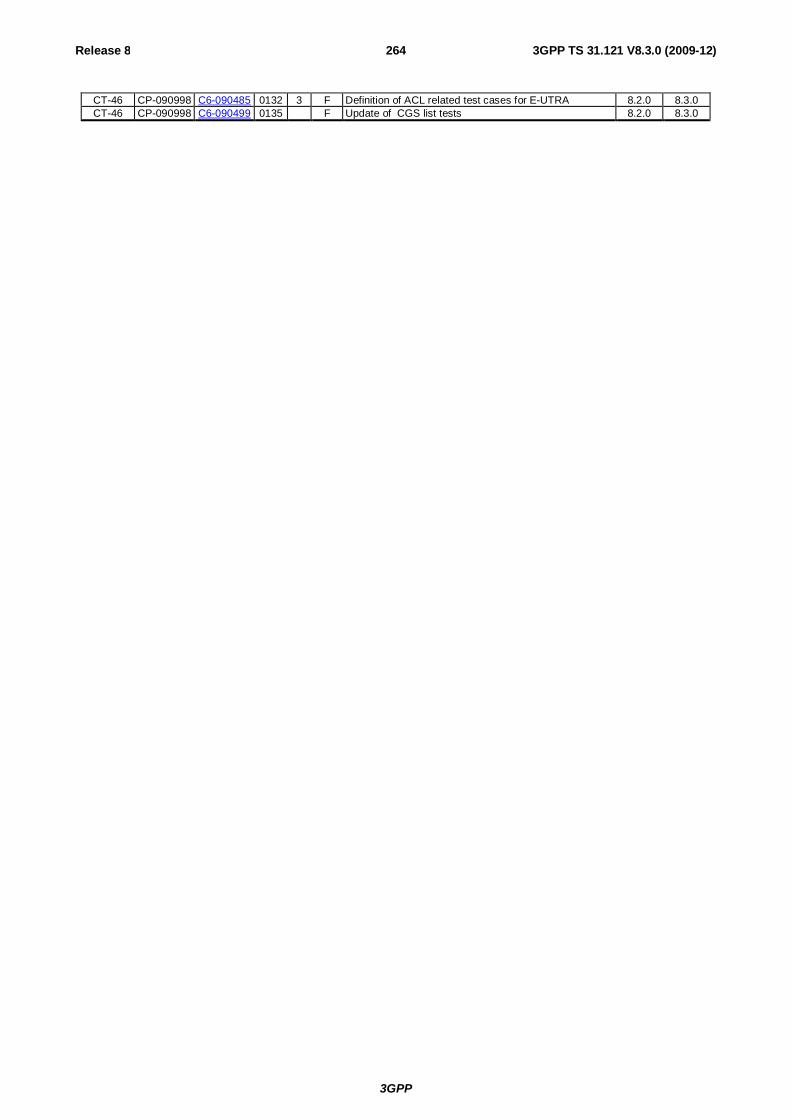
3GPP
Release 8 264 3GPP TS 31.121 V8.3.0 (2009-12)
CT-46 CP-090998 C6-090485 0132 3 F Definition of ACL related test cases for E-UTRA 8.2.0 8.3.0 CT-46 CP-090998 C6-090499 0135 F Update of CGS list tests 8.2.0 8.3.0


![Reverse engineering Erlang softwareerlang.org/euc/04/thomasslides.pdf · Reverse engineering Erlang software ... PMM_Detached ] / Dea locate P-TMSI, ... associate d with the IMSI](https://img.pdfslide.net/doc/110x75/5ab001be7f8b9aa8438e0c78/reverse-engineering-erlang-engineering-erlang-software-pmmdetached-dea.jpg)