Embed Size (px)
Citation preview
1153.1038.49-01 1 07/01
Test and MeasurementDivision
Operating Manual
3GPP WCDMA Mobile Station Test
Application Firmware Module FSIQK731153.1009.02
Printed in the FederalRepublic of Germany

FSIQK73 Contents
1153.1038.42-01 3 E-1
Contents
Safety InstructionsCertificate of QualitySupport Center AddressList of R&S Representatives
Contents of Application Firmware FSIQK73 Manual
3GPP WCDMA Mobile Station Test - Application Firmware FSIQK73.................... 11 Enabling the Firmware Option ................................................................................................ 1
2 Getting Started.......................................................................................................................... 2Basic Settings in Code Domain Measurement Mode................................................................. 3
Measurement 1: Measuring the Signal Power ........................................................................... 3
Measurement 2: Measurement of DPCCH in Vector Signal Analyzer Mode ............................. 4
Setting: Synchronizing the reference frequencies...................................................................... 4
Measurement 3: Measurement of Relative Code Domain Power .............................................. 5
Setting: Behaviour with Deviating Center Frequency Setting .................................................... 6
Setting: Behaviour with Incorrect Scrambling Code................................................................... 6
Measurement 4: Triggered Measurement of Relative Code Domain Power ............................. 7
Setting: Trigger offset ................................................................................................................. 7
Measurement 5: Measurement of Modulation Accuracy...................................................... 8
Measurement 6: Measurement of Peak Code Domain Errors ................................................... 9
3 Setup for Mobile Station Tests.............................................................................................. 10Standard Test Setup................................................................................................................. 10
Presetting.................................................................................................................................. 11
4 Channel Configuration........................................................................................................... 12
5 Menu Overview ....................................................................................................................... 13
6 Configuration of WCDMA Measurements............................................................................ 15Measurement of Channel Power.............................................................................................. 16
Measurement of Adjacent-Channel Power - ACLR.................................................................. 17
Signal Power Check – SPECTRUM EM MASK ....................................................................... 18
Measurement of Occupied Bandwidth - OCCUPIED BANDWIDTH ........................................ 20
Spectrum Measurement - SPECTRUM.................................................................................... 21
Measurement of Crest Factor - TIME DOMAIN ....................................................................... 22
Signal Statistics - CCDF......................................................................................................... 24
Code Domain Measurements on WCDMA Signals ............................................................. 26Continuous Measurement - Continuous Sweep ............................................................ 27Single Measurement - Single Sweep............................................................................. 27Display Mode - RESULT DISPLAY................................................................................ 28Measurement Configuration........................................................................................... 43MARKER Functions ....................................................................................................... 47Configuration of CDP Measurement – MEAS SETTINGS............................................ 48Level Settings – REV LEVEL ......................................................................................... 51Automatic Adaptation to Input Level - LEVEL AUTO ADJUST...................................... 51Automatic Setting of CDP Measurement Mode - CDP AUTO ADJUST ........................ 52TRACE Key Group......................................................................................................... 53
Contents FSIQK73
1153.1038.42-01 4 E-1
Trace Settings - TRACE Key Group .............................................................................. 53
Overview of Other Menus......................................................................................................... 59SYSTEM Key Group ...................................................................................................... 59CONFIGURATION Key Group....................................................................................... 59FREQUENCY Key Group .............................................................................................. 59LEVEL Key Group, INPUT Key...................................................................................... 59MARKER Key Group...................................................................................................... 59LINES Key Group........................................................................................................... 59SWEEP Key Group ........................................................................................................ 60HCOPY and MEMORY Key Group ................................................................................ 60
7 Remote-Control Commands.................................................................................................. 61CALCulate Subsystem ............................................................................................................ 61
CALCulate:STATistics - Subsystem......................................................................................... 64
CONFigure:WCDPower Subsystem......................................................................................... 65
INSTrument Subsystem ........................................................................................................... 67
SENSe:CDPower Subsystem .................................................................................................. 68
TRACe Subsystem ................................................................................................................... 70
Alphabetical List of Commands................................................................................................ 72
Table of Softkeys with Assignment of IEC/IEEE Commands................................................... 73CONFIGURATION Key Group....................................................................................... 73
STATus QUEStionable:SYNC Register ................................................................................... 77
8 Performance Test ................................................................................................................... 78Required Measuring Equipment and Accessories ................................................................... 78
Test Procedure ......................................................................................................................... 78
Performance Test Report ......................................................................................................... 81
9 Glossary .................................................................................................................................. 82
10 Index ........................................................................................................................................ 83
FSIQK73 Contents
1153.1038.42-01 5 E-1
Figures
Fig. 3-1 MS test setup............................................................................................................................ 10
Fig. 5-1 Overview of menus................................................................................................................... 13
Fig. 5-2 Overview of menus – CODE DOM POWER ............................................................................ 14
Fig. 6-1 Power measurement in the 3.84 MHz transmission channel ................................................... 16
Fig. 6-2 Adjacent-channel power measurement of a WCDMA mobile station. ..................................... 17
Fig. 6-3 Measurement of spectrum emission mask............................................................................... 18
Fig. 6-4 Measurement of occupied bandwidth....................................................................................... 20
Fig. 6-5 Spectrum display of WCDMA signal at a 25 MHz span. .......................................................... 21
Fig. 6-6 Time domain display of WCDMA signal. .................................................................................. 22
Fig. 6-7 CCDF of WCDMA signal .......................................................................................................... 24
Fig. 6-8 Indication of measurement parameters.................................................................................. 29
Fig. 6-9 CDP diagram (relative scaling)................................................................................................. 30
Fig. 6-10 Code domain power display mode with absolute scaling......................................................... 31
Fig. 6-11 Overview display....................................................................................................................... 32
Fig. 6-12 Zoomed representation of the CDP diagram ........................................................................... 33
Fig. 6-13 Modulation Accuracy ................................................................................................................ 34
Fig. 6-14 Peak Code Domain Error ......................................................................................................... 35
Fig. 6-15 Power versus Slot measurement for a channel with power control ......................................... 36
Fig. 6-16 Result Summary....................................................................................................................... 37
Fig. 6-17 Channel Table .......................................................................................................................... 39
Fig. 6-18 Symbol Constellation Diagram, I mapping ............................................................................... 40
Fig. 6-19 Symbol Constellation Diagram, Q mapping ............................................................................. 40
Fig. 6-20 Error Vector Magnitude for the selected slot of the selected channel...................................... 41
Fig. 6-21 Demodulated bits for the selected slot of the selected channel ............................................... 41
Fig. 6-22 Table for editing a channel configuration ................................................................................. 44
Fig. 6-23 Parameters of the marker info field .......................................................................................... 47
Contents FSIQK73
1153.1038.42-01 6 E-1
Tables
Table 2-1Default settings of the code domain measurement.................................................................... 3
Table 4-1Channel configuration 1: DPCCH and 1 DPDCH..................................................................... 12
Table 4-2Channel configuration 2: DPCCH to 6 DPDCH........................................................................ 12
Table 7-1Meaning of bits in STATus:QUEStionable:SYNC register ....................................................... 77
Table 8-1Required Measuring Equipment and Accessories ................................................................... 78
Table 8-2Performance Test Report ......................................................................................................... 81

1171.0000.42-02.00 Sheet 1
Before putting the product into operation for the first time, make sure to read the following
S a f e t y I n s t r u c t i o n s
Rohde & Schwarz makes every effort to keep the safety standard of its products up to date and to offer its customers the highest possible degree of safety. Our products and the auxiliary equipment required for them are designed and tested in accordance with the relevant safety standards. Compliance with these standards is continuously monitored by our quality assurance system. This product has been designed and tested in accordance with the EC Certificate of Conformity and has left the manufacturers plant in a condition fully complying with safety standards. To maintain this condition and to ensure safe operation, observe all instructions and warnings provided in this manual. If you have any questions regarding these safety instructions, Rohde & Schwarz will be happy to answer them.
Furthermore, it is your responsibility to use the product in an appropriate manner. This product is designed for use solely in industrial and laboratory environments or in the field and must not be used in any way that may cause personal injury or property damage. You are responsible if the product is used for an intention other than its designated purpose or in disregard of the manufacturer's instructions. The manufacturer shall assume no responsibility for such use of the product.
The product is used for its designated purpose if it is used in accordance with its operating manual and within its performance limits (see data sheet, documentation, the following safety instructions). Using the products requires technical skills and knowledge of English. It is therefore essential that the products be used exclusively by skilled and specialized staff or thoroughly trained personnel with the required skills. If personal safety gear is required for using Rohde & Schwarz products, this will be indicated at the appropriate place in the product documentation.
Symbols and safety labels
Observe operating instructions
Weight indication for units >18 kg
Danger of electric shock
Warning! Hot surface
PE terminal Ground Ground terminal
Attention! Electrostatic sensitive devices
Supply voltage ON/OFF
Standby indication
Direct current (DC)
Alternating current (AC)
Direct/alternating current (DC/AC)
Device fully protected by double/reinforced insulation

Safety Instructions
1171.0000.42-02.00 Sheet 2
Observing the safety instructions will help prevent personal injury or damage of any kind caused by dangerous situations. Therefore, carefully read through and adhere to the following safety instructions before putting the product into operation. It is also absolutely essential to observe the additional safety instructions on personal safety that appear in other parts of the documentation. In these safety instructions, the word "product" refers to all merchandise sold and distributed by Rohde & Schwarz, including instruments, systems and all accessories.
Tags and their meaning DANGER This tag indicates a safety hazard with a high potential of risk for the
user that can result in death or serious injuries. WARNING This tag indicates a safety hazard with a medium potential of risk for the
user that can result in death or serious injuries. CAUTION This tag indicates a safety hazard with a low potential of risk for the user
that can result in slight or minor injuries. ATTENTION This tag indicates the possibility of incorrect use that can cause damage
to the product. NOTE This tag indicates a situation where the user should pay special attention
to operating the product but which does not lead to damage. These tags are in accordance with the standard definition for civil applications in the European Economic Area. Definitions that deviate from the standard definition may also exist. It is therefore essential to make sure that the tags described here are always used only in connection with the associated documentation and the associated product. The use of tags in connection with unassociated products or unassociated documentation can result in misinterpretations and thus contribute to personal injury or material damage.
Basic safety instructions 1. The product may be operated only under
the operating conditions and in the positions specified by the manufacturer. Its ventilation must not be obstructed during operation. Unless otherwise specified, the following requirements apply to Rohde & Schwarz products: prescribed operating position is always with the housing floor facing down, IP protection 2X, pollution severity 2, overvoltage category 2, use only in enclosed spaces, max. operation altitude max. 2000 m. Unless specified otherwise in the data sheet, a tolerance of ±10% shall apply to the nominal voltage and of ±5% to the nominal frequency.
2. Applicable local or national safety regulations and rules for the prevention of accidents must be observed in all work performed. The product may be opened only by authorized, specially trained personnel. Prior to performing any work on the product or opening the product, the
product must be disconnected from the supply network. Any adjustments, replacements of parts, maintenance or repair must be carried out only by technical personnel authorized by Rohde & Schwarz. Only original parts may be used for replacing parts relevant to safety (e.g. power switches, power transformers, fuses). A safety test must always be performed after parts relevant to safety have been replaced (visual inspection, PE conductor test, insulation resistance measurement, leakage current measurement, functional test).
3. As with all industrially manufactured goods, the use of substances that induce an allergic reaction (allergens, e.g. nickel) such as aluminum cannot be generally excluded. If you develop an allergic reaction (such as a skin rash, frequent sneezing, red eyes or respiratory difficulties), consult a physician immediately to determine the cause.
Safety Instructions
1171.0000.42-02.00 Sheet 3
4. If products/components are mechanically and/or thermically processed in a manner that goes beyond their intended use, hazardous substances (heavy-metal dust such as lead, beryllium, nickel) may be released. For this reason, the product may only be disassembled, e.g. for disposal purposes, by specially trained personnel. Improper disassembly may be hazardous to your health. National waste disposal regulations must be observed.
5. If handling the product yields hazardous substances or fuels that must be disposed of in a special way, e.g. coolants or engine oils that must be replenished regularly, the safety instructions of the manufacturer of the hazardous substances or fuels and the applicable regional waste disposal regulations must be observed. Also observe the relevant safety instructions in the product documentation.
6. Depending on the function, certain products such as RF radio equipment can produce an elevated level of electromagnetic radiation. Considering that unborn life requires increased protection, pregnant women should be protected by appropriate measures. Persons with pacemakers may also be endangered by electromagnetic radiation. The employer is required to assess workplaces where there is a special risk of exposure to radiation and, if necessary, take measures to avert the danger.
7. Operating the products requires special training and intense concentration. Make certain that persons who use the products are physically, mentally and emotionally fit enough to handle operating the products; otherwise injuries or material damage may occur. It is the responsibility of the employer to select suitable personnel for operating the products.
8. Prior to switching on the product, it must be ensured that the nominal voltage setting on the product matches the nominal voltage of the AC supply network. If a different voltage is to be set, the power fuse of the product may have to be changed accordingly.
9. In the case of products of safety class I with movable power cord and connector, operation is permitted only on sockets with earthing contact and protective earth connection.
10. Intentionally breaking the protective earth connection either in the feed line or in the product itself is not permitted. Doing so can result in the danger of an electric shock from the product. If extension cords or connector strips are implemented, they must be checked on a regular basis to ensure that they are safe to use.
11. If the product has no power switch for disconnection from the AC supply, the plug of the connecting cable is regarded as the disconnecting device. In such cases, it must be ensured that the power plug is easily reachable and accessible at all times (length of connecting cable approx. 2 m). Functional or electronic switches are not suitable for providing disconnection from the AC supply. If products without power switches are integrated in racks or systems, a disconnecting device must be provided at the system level.
12. Never use the product if the power cable is damaged. By taking appropriate safety measures and carefully laying the power cable, ensure that the cable cannot be damaged and that no one can be hurt by e.g. tripping over the cable or suffering an electric shock.
13. The product may be operated only from TN/TT supply networks fused with max. 16 A.
14. Do not insert the plug into sockets that are dusty or dirty. Insert the plug firmly and all the way into the socket. Otherwise this can result in sparks, fire and/or injuries.
15. Do not overload any sockets, extension cords or connector strips; doing so can cause fire or electric shocks.
16. For measurements in circuits with voltages Vrms > 30 V, suitable measures (e.g. appropriate measuring equipment, fusing, current limiting, electrical separation, insulation) should be taken to avoid any hazards.
17. Ensure that the connections with information technology equipment comply with IEC 950/EN 60950.
18. Never remove the cover or part of the housing while you are operating the product. This will expose circuits and components and can lead to injuries, fire or damage to the product.
Safety Instructions
1171.0000.42-02.00 Sheet 4
19. If a product is to be permanently installed, the connection between the PE terminal on site and the product's PE conductor must be made first before any other connection is made. The product may be installed and connected only by a skilled electrician.
20. For permanently installed equipment without built-in fuses, circuit breakers or similar protective devices, the supply circuit must be fused in such a way that suitable protection is provided for users and products.
21. Do not insert any objects into the openings in the housing that are not designed for this purpose. Never pour any liquids onto or into the housing. This can cause short circuits inside the product and/or electric shocks, fire or injuries.
22. Use suitable overvoltage protection to ensure that no overvoltage (such as that caused by a thunderstorm) can reach the product. Otherwise the operating personnel will be endangered by electric shocks.
23. Rohde & Schwarz products are not protected against penetration of water, unless otherwise specified (see also safety instruction 1.). If this is not taken into account, there exists the danger of electric shock or damage to the product, which can also lead to personal injury.
24. Never use the product under conditions in which condensation has formed or can form in or on the product, e.g. if the product was moved from a cold to a warm environment.
25. Do not close any slots or openings on the product, since they are necessary for ventilation and prevent the product from overheating. Do not place the product on soft surfaces such as sofas or rugs or inside a closed housing, unless this is well ventilated.
26. Do not place the product on heat-generating devices such as radiators or fan heaters. The temperature of the environment must not exceed the maximum temperature specified in the data sheet.
27. Batteries and storage batteries must not be exposed to high temperatures or fire. Keep batteries and storage batteries away from children. If batteries or storage batteries are improperly replaced, this can cause an explosion (warning: lithium cells). Replace the battery or storage battery only with the
matching Rohde & Schwarz type (see spare parts list). Batteries and storage batteries are hazardous waste. Dispose of them only in specially marked containers. Observe local regulations regarding waste disposal. Do not short-circuit batteries or storage batteries.
28. Please be aware that in the event of a fire, toxic substances (gases, liquids etc.) that may be hazardous to your health may escape from the product.
29. Please be aware of the weight of the product. Be careful when moving it; otherwise you may injure your back or other parts of your body.
30. Do not place the product on surfaces, vehicles, cabinets or tables that for reasons of weight or stability are unsuitable for this purpose. Always follow the manufacturer's installation instructions when installing the product and fastening it to objects or structures (e.g. walls and shelves).
31. Handles on the products are designed exclusively for personnel to hold or carry the product. It is therefore not permissible to use handles for fastening the product to or on means of transport such as cranes, fork lifts, wagons, etc. The user is responsible for securely fastening the products to or on the means of transport and for observing the safety regulations of the manufacturer of the means of transport. Noncompliance can result in personal injury or material damage.
32. If you use the product in a vehicle, it is the sole responsibility of the driver to drive the vehicle safely. Adequately secure the product in the vehicle to prevent injuries or other damage in the event of an accident. Never use the product in a moving vehicle if doing so could distract the driver of the vehicle. The driver is always responsible for the safety of the vehicle; the manufacturer assumes no responsibility for accidents or collisions.
33. If a laser product (e.g. a CD/DVD drive) is integrated in a Rohde & Schwarz product, do not use any other settings or functions than those described in the documentation. Otherwise this may be hazardous to your health, since the laser beam can cause irreversible damage to your eyes. Never try to take such products apart, and never look into the laser beam.
1171.0000.42-02.00 página 1
Por favor lea imprescindiblemente antes de la primera puesta en funcionamiento las siguientes informaciones de seguridad
Informaciones de seguridad
Es el principio de Rohde & Schwarz de tener a sus productos siempre al día con los estandards de seguridad y de ofrecer a sus clientes el máximo grado de seguridad. Nuestros productos y todos los equipos adicionales son siempre fabricados y examinados según las normas de seguridad vigentes. Nuestra sección de gestión de la seguridad de calidad controla constantemente que sean cumplidas estas normas. Este producto ha sido fabricado y examinado según el comprobante de conformidad adjunto según las normas de la CE y ha salido de nuestra planta en estado impecable según los estandards técnicos de seguridad. Para poder preservar este estado y garantizar un funcionamiento libre de peligros, deberá el usuario atenerse a todas las informaciones, informaciones de seguridad y notas de alerta. Rohde&Schwarz está siempre a su disposición en caso de que tengan preguntas referentes a estas informaciones de seguridad.
Además queda en la responsabilidad del usuario utilizar el producto en la forma debida. Este producto solamente fue elaborado para ser utilizado en la indústria y el laboratorio o para fines de campo y de ninguna manera deberá ser utilizado de modo que alguna persona/cosa pueda ser dañada. El uso del producto fuera de sus fines definidos o despreciando las informaciones de seguridad del fabricante queda en la responsabilidad del usuario. El fabricante no se hace en ninguna forma responsable de consecuencias a causa del maluso del producto.
Se parte del uso correcto del producto para los fines definidos si el producto es utilizado dentro de las instrucciones del correspondiente manual del uso y dentro del margen de rendimiento definido (ver hoja de datos, documentación, informaciones de seguridad que siguen). El uso de los productos hace necesarios conocimientos profundos y el conocimiento del idioma inglés. Por eso se deberá tener en cuenta de exclusivamente autorizar para el uso de los productos a personas péritas o debidamente minuciosamente instruidas con los conocimientos citados. Si fuera necesaria indumentaria de seguridad para el uso de productos de R&S, encontrará la información debida en la documentación del producto en el capítulo correspondiente.
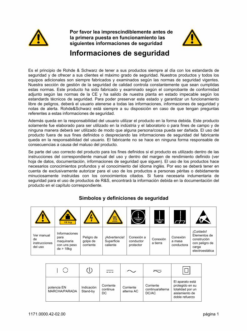
Símbolos y definiciones de seguridad
Ver manual de instrucciones del uso
Informaciones para maquinaria con uns peso de > 18kg
Peligro de golpe de corriente
¡Advertencia! Superficie caliente
Conexión a conductor protector
Conexión a tierra
Conexión a masa conductora
¡Cuidado! Elementos de construción con peligro de carga electroestática
potencia EN MARCHA/PARADA
Indicación Stand-by
Corriente continua DC
Corriente alterna AC
Corriente continua/alterna DC/AC
El aparato está protegido en su totalidad por un aislamiento de doble refuerzo
Informaciones de seguridad
1171.0000.42-02.00 página 2
Tener en cuenta las informaciones de seguridad sirve para tratar de evitar daños y peligros de toda clase. Es necesario de que se lean las siguientes informaciones de seguridad concienzudamente y se tengan en cuenta debidamente antes de la puesta en funcionamiento del producto. También deberán ser tenidas en cuenta las informaciones para la protección de personas que encontrarán en otro capítulo de esta documentación y que también son obligatorias de seguir. En las informaciones de seguridad actuales hemos juntado todos los objetos vendidos por Rohde&Schwarz bajo la denominación de producto, entre ellos también aparatos, instalaciones así como toda clase de accesorios.
Palabras de señal y su significado PELIGRO Indica un punto de peligro con gran potencial de riesgo para el
ususario.Punto de peligro que puede llevar hasta la muerte o graves heridas.
ADVERTENCIA Indica un punto de peligro con un protencial de riesgo mediano para el usuario. Punto de peligro que puede llevar hasta la muerte o graves heridas .
ATENCIÓN Indica un punto de peligro con un protencial de riesgo pequeño para el usuario. Punto de peligro que puede llevar hasta heridas leves o pequeñas
CUIDADO Indica la posibilidad de utilizar mal el producto y a consecuencia dañarlo.
INFORMACIÓN Indica una situación en la que deberían seguirse las instrucciones en el uso del producto, pero que no consecuentemente deben de llevar a un daño del mismo.
Las palabras de señal corresponden a la definición habitual para aplicaciones civiles en el ámbito de la comunidad económica europea. Pueden existir definiciones diferentes a esta definición. Por eso se debera tener en cuenta que las palabras de señal aquí descritas sean utilizadas siempre solamente en combinación con la correspondiente documentación y solamente en combinación con el producto correspondiente. La utilización de las palabras de señal en combinación con productos o documentaciones que no les correspondan puede llevar a malinterpretaciones y tener por consecuencia daños en personas u objetos.
Informaciones de seguridad elementales 1. El producto solamente debe ser utilizado
según lo indicado por el fabricante referente a la situación y posición de funcionamiento sin que se obstruya la ventilación. Si no se convino de otra manera, es para los productos R&S válido lo que sigue: como posición de funcionamiento se define principialmente la posición con el suelo de la caja para abajo , modo de protección IP 2X, grado de suciedad 2, categoría de sobrecarga eléctrica 2, utilizar solamente en estancias interiores, utilización hasta 2000 m sobre el nivel del mar. A menos que se especifique otra cosa en la hoja de datos, se aplicará una tolerancia de ±10% sobre el voltaje nominal y de ±5% sobre la frecuencia nominal.
2. En todos los trabajos deberán ser tenidas en cuenta las normas locales de seguridad de trabajo y de prevención de accidentes. El producto solamente debe de ser abierto por personal périto autorizado. Antes de efectuar trabajos en el producto o abrirlo deberá este ser desconectado de la corriente. El ajuste, el cambio de partes, la manutención y la reparación deberán ser solamente efectuadas por electricistas autorizados por R&S. Si se reponen partes con importancia para los aspectos de seguridad (por ejemplo el enchufe, los transformadores o los fusibles), solamente podrán ser sustituidos por partes originales. Despues de cada recambio de partes elementales para la seguridad deberá ser efectuado un control de
Informaciones de seguridad
1171.0000.42-02.00 página 3
seguridad (control a primera vista, control de conductor protector, medición de resistencia de aislamiento, medición de medición de la corriente conductora, control de funcionamiento).
3. Como en todo producto de fabricación industrial no puede ser excluido en general de que se produzcan al usarlo elementos que puedan generar alergias, los llamados elementos alergénicos (por ejemplo el níquel). Si se producieran en el trato con productos R&S reacciones alérgicas, como por ejemplo urticaria, estornudos frecuentes, irritación de la conjuntiva o dificultades al respirar, se deberá consultar inmediatamente a un médico para averigurar los motivos de estas reacciones.
4. Si productos / elementos de construcción son tratados fuera del funcionamiento definido de forma mecánica o térmica, pueden generarse elementos peligrosos (polvos de sustancia de metales pesados como por ejemplo plomo, berilio, níquel). La partición elemental del producto, como por ejemplo sucede en el tratamiento de materias residuales, debe de ser efectuada solamente por personal especializado para estos tratamientos. La partición elemental efectuada inadecuadamente puede generar daños para la salud. Se deben tener en cuenta las directivas nacionales referentes al tratamiento de materias residuales.
5. En el caso de que se produjeran agentes de peligro o combustibles en la aplicación del producto que debieran de ser transferidos a un tratamiento de materias residuales, como por ejemplo agentes refrigerantes que deben ser repuestos en periodos definidos, o aceites para motores, deberan ser tenidas en cuenta las prescripciones de seguridad del fabricante de estos agentes de peligro o combustibles y las regulaciones regionales para el tratamiento de materias residuales. Cuiden también de tener en cuenta en caso dado las prescripciones de seguridad especiales en la descripción del producto.
6. Ciertos productos, como por ejemplo las instalaciones de radiación HF, pueden a causa de su función natural, emitir una radiación electromagnética aumentada. En vista a la protección de la vida en desarrollo deberían ser protegidas personas embarazadas debidamente. También las personas con un bypass pueden correr
peligro a causa de la radiación electromagnética. El empresario está comprometido a valorar y señalar areas de trabajo en las que se corra un riesgo de exposición a radiaciones aumentadas de riesgo aumentado para evitar riesgos.
7. La utilización de los productos requiere instrucciones especiales y una alta concentración en el manejo. Debe de ponerse por seguro de que las personas que manejen los productos estén a la altura de los requerimientos necesarios referente a sus aptitudes físicas, psíquicas y emocionales, ya que de otra manera no se pueden excluir lesiones o daños de objetos. El empresario lleva la responsabilidad de seleccionar el personal usuario apto para el manejo de los productos.
8. Antes de la puesta en marcha del producto se deberá tener por seguro de que la tensión preseleccionada en el producto equivalga a la del la red de distribución. Si es necesario cambiar la preselección de la tensión también se deberán en caso dabo cambiar los fusibles correspondientes del prodcuto.
9. Productos de la clase de seguridad I con alimentación móvil y enchufe individual de producto solamente deberán ser conectados para el funcionamiento a tomas de corriente de contacto de seguridad y con conductor protector conectado.
10. Queda prohibida toda clase de interrupción intencionada del conductor protector, tanto en la toma de corriente como en el mismo producto ya que puede tener como consecuencia el peligro de golpe de corriente por el producto. Si se utilizaran cables o enchufes de extensión se deberá poner al seguro, que es controlado su estado técnico de seguridad.
11. Si el producto no está equipado con un interruptor para desconectarlo de la red, se deberá considerar el enchufe del cable de distribución como interruptor. En estos casos deberá asegurar de que el enchufe sea de fácil acceso y nabejo (medida del cable de distribución aproximadamente 2 m). Los interruptores de función o electrónicos no son aptos para el corte de la red eléctrica. Si los productos sin interruptor están integrados en construciones o instalaciones, se deberá instalar el interruptor al nivel de la instalación.
Informaciones de seguridad
1171.0000.42-02.00 página 4
12. No utilice nunca el producto si está dañado el cable eléctrico. Asegure a través de las medidas de protección y de instalación adecuadas de que el cable de eléctrico no pueda ser dañado o de que nadie pueda ser dañado por él, por ejemplo al tropezar o por un golpe de corriente.
13. Solamente está permitido el funcionamiento en redes de distribución TN/TT aseguradas con fusibles de como máximo 16 A.
14. Nunca conecte el enchufe en tomas de corriente sucias o llenas de polvo. Introduzca el enchufe por completo y fuertemente en la toma de corriente. Si no tiene en consideración estas indicaciones se arriesga a que se originen chispas, fuego y/o heridas.
15. No sobrecargue las tomas de corriente, los cables de extensión o los enchufes de extensión ya que esto pudiera causar fuego o golpes de corriente.
16. En las mediciones en circuitos de corriente con una tensión de entrada de Ueff > 30 V se deberá tomar las precauciones debidas para impedir cualquier peligro (por ejemplo medios de medición adecuados, seguros, limitación de tensión, corte protector, aislamiento etc.).
17. En caso de conexión con aparatos de la técnica informática se deberá tener en cuenta que estos cumplan los requisitos de la EC950/EN60950.
18. Nunca abra la tapa o parte de ella si el producto está en funcionamiento. Esto pone a descubierto los cables y componentes eléctricos y puede causar heridas, fuego o daños en el producto.
19. Si un producto es instalado fijamente en un lugar, se deberá primero conectar el conductor protector fijo con el conductor protector del aparato antes de hacer cualquier otra conexión. La instalación y la conexión deberán ser efecutadas por un electricista especializado.
20. En caso de que los productos que son instalados fijamente en un lugar sean sin protector implementado, autointerruptor o similares objetos de protección, deberá la toma de corriente estar protegida de manera que los productos o los usuarios estén suficientemente protegidos.
21. Por favor, no introduzca ningún objeto que no esté destinado a ello en los orificios de la caja del aparato. No vierta nunca ninguna clase de líquidos sobre o en la caja. Esto puede producir corto circuitos en el producto y/o puede causar golpes de corriente, fuego o heridas.
22. Asegúrese con la protección adecuada de que no pueda originarse en el producto una sobrecarga por ejemplo a causa de una tormenta. Si no se verá el personal que lo utilice expuesto al peligro de un golpe de corriente.
23. Los productos R&S no están protegidos contra el agua si no es que exista otra indicación, ver también punto 1. Si no se tiene en cuenta esto se arriesga el peligro de golpe de corriente o de daños en el producto lo cual también puede llevar al peligro de personas.
24. No utilice el producto bajo condiciones en las que pueda producirse y se hayan producido líquidos de condensación en o dentro del producto como por ejemplo cuando se desplaza el producto de un lugar frío a un lugar caliente.
25. Por favor no cierre ninguna ranura u orificio del producto, ya que estas son necesarias para la ventilación e impiden que el producto se caliente demasiado. No pongan el producto encima de materiales blandos como por ejemplo sofás o alfombras o dentro de una caja cerrada, si esta no está suficientemente ventilada.
26. No ponga el producto sobre aparatos que produzcan calor, como por ejemplo radiadores o calentadores. La temperatura ambiental no debe superar la temperatura máxima especificada en la hoja de datos.
Informaciones de seguridad
1171.0000.42-02.00 página 5
27. Baterías y acumuladores no deben de ser expuestos a temperaturas altas o al fuego. Guardar baterías y acumuladores fuera del alcance de los niños. Si las baterías o los acumuladores no son cambiados con la debida atención existirá peligro de explosión (atención celulas de Litio). Cambiar las baterías o los acumuladores solamente por los del tipo R&S correspondiente (ver lista de piezas de recambio). Baterías y acumuladores son deshechos problemáticos. Por favor tirenlos en los recipientes especiales para este fín. Por favor tengan en cuenta las prescripciones nacionales de cada país referente al tratamiento de deshechos. Nunca sometan las baterías o acumuladores a un corto circuito.
28. Tengan en consideración de que en caso de un incendio pueden escaparse gases tóxicos del producto, que pueden causar daños a la salud.
29. Por favor tengan en cuenta que en caso de un incendio pueden desprenderse del producto agentes venenosos (gases, líquidos etc.) que pueden generar daños a la salud.
30. No sitúe el producto encima de superficies, vehículos, estantes o mesas, que por sus características de peso o de estabilidad no sean aptas para él. Siga siempre las instrucciones de instalación del fabricante cuando instale y asegure el producto en objetos o estructuras (por ejemplo paredes y estantes).
31. Las asas instaladas en los productos sirven solamente de ayuda para el manejo que solamente está previsto para personas. Por eso no está permitido utilizar las asas para la sujecion en o sobre medios de transporte como por ejemplo grúas, carretillas elevadoras de horquilla, carros etc. El usuario es responsable de que los productos sean sujetados de forma segura a los medios de transporte y de que las prescripciones de seguridad del fabricante de los medios de transporte sean tenidas en cuenta. En caso de que no se tengan en cuenta pueden causarse daños en personas y objetos.
32. Si llega a utilizar el producto dentro de un vehículo, queda en la responsabilidad absoluta del conductor que conducir el vehículo de manera segura. Asegure el producto dentro del vehículo debidamente para evitar en caso de un accidente las lesiones u otra clase de daños. No utilice nunca el producto dentro de un vehículo en movimiento si esto pudiera distraer al conductor. Siempre queda en la responsabilidad absoluta del conductor la seguridad del vehículo y el fabricante no asumirá ninguna clase de responsabilidad por accidentes o colisiones.
33. Dado el caso de que esté integrado un producto de laser en un producto R&S (por ejemplo CD/DVD-ROM) no utilice otras instalaciones o funciones que las descritas en la documentación. De otra manera pondrá en peligro su salud, ya que el rayo laser puede dañar irreversiblemente sus ojos. Nunca trate de descomponer estos productos. Nunca mire dentro del rayo laser.

FSIQK73 Manual
1153.1038.42 0.1 E-1
Contents of Manual for Application Firmware FSIQK73
This manual contains all information on the operation of FSIQ equipped with Application FirmwareFSIQK73. It includes operation via menus and the remote-control commands for the 3GPP WCDMAmobile station test.
The manual comprises the data sheet and 10 chapters:
The data sheet informs on the guaranteed specifications and the firmware characteristics.
Chapter 1 describes how to enable the application firmware module.
Chapter 2 describes typical examples of measurements by means of tests.
Chapter 3 describes the measurement setup for mobile station tests.
Chapter 4 describes possible channel configurations for the mobile station signal.
Chapter 5 gives a schematic overview of the WCDMA control menus.
Chapter 6 contains a detailed description of the possible mobile station test measurementsas a reference for manual operation The chapter also presents a list of remote-control commands associated with each function.
Chapter 7 describes all remote-control commands defined for the code domainmeasurement. An alphabetic list of all remote-control commands and a table ofsoftkeys with the assignment of commands are given at the end of this chapter.
Chapter 8 contains the performance test.
Chapter 9 contains the glossary.
Chapter 10 contains the index of this operating manual.
This manual is a supplement to the FSIQ operating manual. It includes exclusively functions ofApplication Firmware FSIQK73. For all other descriptions, please refer to the FSIQ operatingmanual.

FSIQK73 Enabling the Firmware Option
1153.1038.42 1 E-1
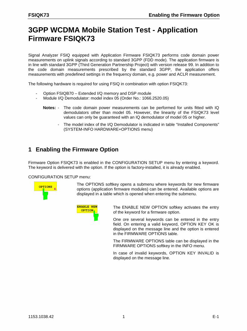
3GPP WCDMA Mobile Station Test - ApplicationFirmware FSIQK73
Signal Analyzer FSIQ equipped with Application Firmware FSIQK73 performs code domain powermeasurements on uplink signals according to standard 3GPP (FDD mode). The application firmware isin line with standard 3GPP (Third Generation Partnership Project) with version release 99. In addition tothe code domain measurements prescribed by the standard 3GPP, the application offersmeasurements with predefined settings in the frequency domain, e.g. power and ACLR measurement.
The following hardware is required for using FSIQ in combination with option FSIQK73:
- Option FSIQB70 – Extended I/Q memory and DSP module- Module I/Q Demodulator: model index 05 (Order No.: 1066.2520.05)
Notes: - The code domain power measurements can be performed for units fitted with IQdemodulators other than model 05. However, the linearity of the FSIQK73 levelvalues can only be guaranteed with an IQ demodulator of model 05 or higher.
- The model index of the I/Q Demodulator is indicated in table “Installed Components”(SYSTEM-INFO HARDWARE+OPTIONS menu)
1 Enabling the Firmware Option
Firmware Option FSIQK73 is enabled in the CONFIGURATION SETUP menu by entering a keyword.The keyword is delivered with the option. If the option is factory-installed, it is already enabled.
CONFIGURATION SETUP menu:
OPTIONSThe OPTIONS softkey opens a submenu where keywords for new firmwareoptions (application firmware modules) can be entered. Available options aredisplayed in a table which is opened when entering the submenu.
ENABLE NEWOPTION
The ENABLE NEW OPTION softkey activates the entryof the keyword for a firmware option.
One ore several keywords can be entered in the entryfield. On entering a valid keyword, OPTION KEY OK isdisplayed on the message line and the option is enteredin the FIRMWARE OPTIONS table.
The FIRMWARE OPTIONS table can be displayed in theFIRMWARE OPTIONS softkey in the INFO menu.
In case of invalid keywords, OPTION KEY INVALID isdisplayed on the message line.
Getting Started FSIQK73
1153.1038.42 2 E-1
2 Getting Started
The following chapter explains basic WCDMA mobile station tests by means of a setup with SignalGenerator SMIQ. It describes how operating and measurement errors can be avoided using correctpresetting.The measurement screen is presented in chapter 6 for each measurement.
Key settings are shown as examples to avoid measurement errors. Following the correct setting, theeffect of an incorrect setting is shown. The following measurements are performed:
• Measurement 1: Measurement of signal power
• Measurement 2: Measurement of DPCCH (Dedicated Physical Common Control Channel) invector analyzer mode
- Setting: Synchronization of reference frequencies
• Measurement 3: Measurement of relative code domain power
- Setting: Setting the analyzer center frequency to the DUT frequency
- Setting: Scrambling code of signal
• Measurement 4: Triggered measurement of relative code domain power
- Setting: Trigger offset
• Measurement 5: Measurement of modulation accuracy
• Measurement 6: Measurement of peak code domain error
The measurements are performed using the following units and accessories:
• Signal Analyzer FSIQ with Application Firmware FSIQK73 WCDMA mobile station test (optionFSIQB70 required)
• Vector Signal Generator SMIQ with option SMIQB43: digital standard WCDMA
(options SMIQB20 and SMIQB11 required)
• 1 coaxial cable, 50 Ω, approx. 1 m, N connector
• 1 coaxial cable, 50 Ω, approx. 1 m, BNC connector
Conventions for displaying settings on FSIQ:
[<KEY>] Press a key on the front panel, e.g. [SPAN]
[<SOFTKEY>] Press a softkey, e.g. [MARKER -> PEAK]
[<nn unit>] Enter a value and terminate by entering the unit, e.g. [12 kHz]
Conventions for displaying settings on SMIQ:
[<KEY>] Press a key on the front panel, e.g. [FREQ]
<MENU> Select a menu, parameter or a setting, e.g. DIGITAL STD.The menu level is marked by an indentation.
<nn unit> Enter a value and terminate by entering the unit, e.g. 12 kHz
FSIQK73 Getting Started
1153.1038.42 3 E-1
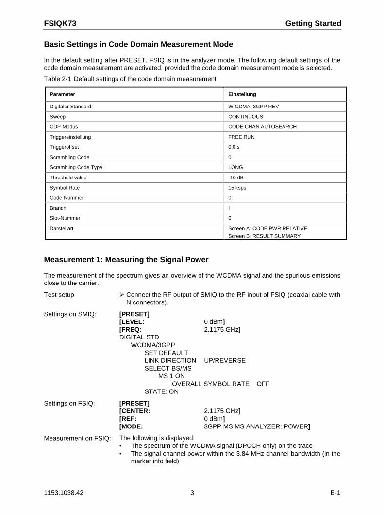
Basic Settings in Code Domain Measurement Mode
In the default setting after PRESET, FSIQ is in the analyzer mode. The following default settings of thecode domain measurement are activated, provided the code domain measurement mode is selected.
Table 2-1 Default settings of the code domain measurement
Parameter Einstellung
Digitaler Standard W-CDMA 3GPP REV
Sweep CONTINUOUS
CDP-Modus CODE CHAN AUTOSEARCH
Triggereinstellung FREE RUN
Triggeroffset 0.0 s
Scrambling Code 0
Scrambling Code Type LONG
Threshold value -10 dB
Symbol-Rate 15 ksps
Code-Nummer 0
Branch I
Slot-Nummer 0
Darstellart Screen A: CODE PWR RELATIVE
Screen B: RESULT SUMMARY
Measurement 1: Measuring the Signal Power
The measurement of the spectrum gives an overview of the WCDMA signal and the spurious emissionsclose to the carrier.
Test setup Connect the RF output of SMIQ to the RF input of FSIQ (coaxial cable withN connectors).
Settings on SMIQ: [PRESET][LEVEL: 0 dBm][FREQ: 2.1175 GHz]DIGITAL STD
WCDMA/3GPPSET DEFAULTLINK DIRECTION UP/REVERSESELECT BS/MS
MS 1 ONOVERALL SYMBOL RATE OFF
STATE: ON
Settings on FSIQ: [PRESET][CENTER: 2.1175 GHz][REF: 0 dBm][MODE: 3GPP MS MS ANALYZER: POWER]
Measurement on FSIQ: The following is displayed:• The spectrum of the WCDMA signal (DPCCH only) on the trace• The signal channel power within the 3.84 MHz channel bandwidth (in the
marker info field)
Getting Started FSIQK73
1153.1038.42 4 E-1
Measurement 2: Measurement of DPCCH in Vector Signal Analyzer Mode
When the WCDMA signal only contains one channel, the signal can be measured in the vector analyzermode of the analyzer. Since each channel is QPSK-modulated after scrambling the total signal isQPSK-modulated also if only one channel is transmitted.The measurement of the QPSK signal allows, for instance, to determine the frequency offset betweenDUT and analyzer.This may be useful for troubleshooting, e.g. if synchronization is not possible during the code domainpower measurement.
Test setup As for measurement 1.
Settings on SMIQ: As for measurement 1
Settings on FSIQ: [PRESET][CENTER: 2.1175 GHz][REF: 0 dBm][MODE: VECTOR ANALYZERDIGITAL STANDARDS W-CDMA 3GPP REV]
Measurement on FSIQ: The following is displayed:• Screen A: Constellation diagram of signal (QPSK)• Screen B: Numeric results of demodulation
Frequency error The frequency error display denotes the frequency offsetbetween the DUT and the analyzer. For a high frequencyoffset (> 1 kHz), the CDP measurements are inaccurateand a synchronization of the analyzer and themeasurement signal is no longer possible. The frequencyoffset can be corrected by tuning the transmitter orcenter frequency of the analyzer. It is recommended tosynchronize the analyzer and the DUT via the referenceinput of the analyzer.
Setting: Synchronizing the reference frequencies
The synchronization of the reference oscillators both of the DUT and analyzer strongly reduces themeasured frequency error.
Test setup Connect the reference input (EXT REF IN/OUT) on the rear panel of theanalyzer to the reference output (REF) on the rear panel of SMIQ (coaxialcable with BNC connectors).
Settings on SMIQ: As for measurement 2
Settings on FSIQ: As for measurement 2, plus[SETUP: REFERENCE EXT]
Measurement on FSIQ: Frequency error The displayed frequency error should be < 10 Hz.
The reference frequencies of the analyzer and of the DUT should be synchronized
FSIQK73 Getting Started
1153.1038.42 5 E-1
Measurement 3: Measurement of Relative Code Domain Power
A code domain power measurement with one of the possible channel configurations is shown in thefollowing. To demonstrate the effects the basic parameters of CDP measurements which allow ananalysis of the signal are changed one after the other from values adapted to the measurement signalto non-adapted values.
Test setup Connect the RF output of SMIQ to the input of FSIQ Connect the reference input (EXT REF IN/OUT) on the rear panel of the
analyzer to the reference input (REF) on the rear panel of SMIQ (coaxialcable with BNC connectors).
Settings on SMIQ: [PRESET][LEVEL: 0 dBm][FREQ: 2.1175 GHz]DIGITAL STD
WCDMA 3GPPLINK DIRECTION UP / REVERSETEST MODELS (NOT STANDARDIZED)...
C+D960KSELECT BS/MS
MS 1 ONOVERALL SYMBOL RATE... 6*960
STATE: ON
Settings on FSIQ: [PRESET][CENTER: 2.1175 GHz][REF: 10 dBm][MODE: 3GPP MS ANALYZER: CODE DOM POWERMEAS SETTINGS SCRAMBLING CODE 0]
Measurement on FSIQ: The following is displayed:Screen A: Code domain power of signal, I component
(channel configuration with 3 data channels in the I branch)Screen B: Numeric results of CDP measurement
Getting Started FSIQK73
1153.1038.42 6 E-1
Setting: Behaviour with Deviating Center Frequency Setting
In the following, the behaviour of the DUT and the analyzer with deviating center frequency setting isshown.
Settings on SMIQ: Tune the center frequency of the signal generator in 1 kHz steps andwatch the analyzer screen:
Measurement on FSIQ: • A CDP measurement on the analyzer is still possible with a frequencyerror of up to approx. 3 kHz. Up to 3 kHz, a frequency error causes noapparent difference in measurement accuracy of the code domain powermeasurement.
• Above a frequency error of 3 kHz, the probability of an impairedsynchronization increases. With continuous measurements, at times allchannels are displayed in blue with almost the same level.
• Above a frequency error of approx. 4 kHz, a CDP measurement cannotbe performed. FSIQ displays all possible codes in blue with a similarlevel.
Settings on SMIQ: Set the signal generator center frequency again to 2.1175 GHz:[FREQ: 2.1175 GHz]
The analyzer center frequency should not differ from the DUT frequency by more than 3 kHz.
Setting: Behaviour with Incorrect Scrambling Code
A valid CDP measurement can only be carried out if the scrambling code set on the analyzer is identicalto the one of the transmitted signal.
Test setup SELECT BS/MSMS 1: ON
SCRAMBLING CODE: 0001(the scrambling code is set to 0000 on the analyzer)
Settings on SMIQ: The CDP display shows all possible codes with approximately the samelevel.
Settings on FSIQ: Set scrambling code to new value:[MODE: 3GPP MS ANALYZER: CODE DOM POWERMEAS SETTINGS SCRAMBLING CODE 1]
Measurement on FSIQ: The CDP display again shows the channel configuration.
The scrambling code setting of the analyzer must be identical to that of the measured signal.
FSIQK73 Getting Started
1153.1038.42 7 E-1
Measurement 4: Triggered Measurement of Relative Code Domain Power
If the code domain power measurement is performed without external triggering, a section ofapproximately 20 ms of the test signal is recorded at an arbitrary moment to detect the start of aWCDMA frame in this section. Depending on the position of the frame start, the required computingtime can be quite long (up to approx. 5 seconds). This can be reduced by applying an external (frame)trigger.
Test setup Connect the RF output of SMIQ to the input of FSIQ Connect the reference input (EXT REF IN/OUT) on the rear panel of FSIQ
to the reference input (REF) on the rear panel of SMIQ (coaxial cable withBNC connectors).
Connect the external trigger input on the rear panel of FSIQ (EXT TRIGGATE) to the external trigger output on the rear panel of SMIQ(TRIGOUT1 of PAR DATA).
Settings on SMIQ: As for measurement 3
Settings on FSIQ: As for measurement 3, plus[MEAS SETTINGS TRIGGER EXT]
Measurement on FSIQ: The following is displayed:Screen A: Code domain power of signal, I component
(channel configuration with 3 data channels in the I branch)Screen B: Numeric results of CDP measurement
Trg to Frame: Offset between trigger event and start of WCDMA frame
The repetition rate of the measurement increases considerably compared tothe repetition rate of a measurement without external trigger.
Setting: Trigger offset
A delay of the trigger event referred to the start of the WCDMA frame can be compensated bymodifying the trigger offset.
Settings on FSIQ: [MODE: 3GPP MS ANALYZER: CODE DOM POWERMEAS SETTINGS EXT TRIG OFFSET 100 µs]
Measurement on FSIQ: The parameter Trg to Frame in the numeric results table (screen B) changes:Trg to Frame -100 µs
A trigger offset compensates analog delays of the trigger event.
Getting Started FSIQK73
1153.1038.42 8 E-1
Measurement 5: Measurement of Modulation Accuracy
The modulation accuracy measurement defined by the 3GPP specifications represents a measurementof the RMS-averaged deviation of the test signal from the ideal signal.An ideal reference signal is generated from the demodulated data. The test signal and the referencesignal are compared with each other. The square deviation yields the modulation accuracy.
Test setup Connect the RF output of SMIQ to the input of FSIQ Connect the reference input (EXT REF IN/OUT) on the rear panel of FSIQ
to the reference input (REF) on the rear panel of SMIQ (coaxial cable withBNC connectors).
Connect the external trigger input on the rear panel of FSIQ (EXT TRIGGATE) to the external trigger output on the rear panel of SMIQ(TRIGOUT1 of PAR DATA).
Settings on SMIQ: [PRESET][LEVEL: 0 dBm][FREQ: 2.1175 GHz]DIGITAL STD
WCDMA 3GPPLINK DIRECTION UP / REVERSETEST MODELS (NOT STANDARDIZED)...
C+D960KSELECT BS/MS
MS 1 ONOVERALL SYMBOL RATE... 6*960
STATE: ON
Settings on FSIQ: [PRESET][CENTER: 2.1175 GHz][REF: 10 dBm][MODE: 3GPP MS ANALYZER: CODE DOM POWERMEAS SETTINGS SCRAMBLING CODE 0
SCR TYPE LONGINACT CHAN THRESHOLD -10TRIGGER EXT
[menu change key UP]RESULT DISPLAY MODULATION ACCURACY]
Measurement on FSIQ: The following is displayed:Screen A: Code domain power of signal, I component
(channel configuration with 3 active channels in the I branch)Screen B: Modulation accuracy (EVM for total signal)
FSIQK73 Getting Started
1153.1038.42 9 E-1
Measurement 6: Measurement of Peak Code Domain Errors
The peak code domain error measurement is defined in the 3GPP specification for WCDMA signals.An ideal reference signal is generated from the demodulated data. The test signal and the referencesignal are compared with each other. The difference of the two signals is projected onto the classes ofthe different spreading factors. The peak code domain error measurement is obtained by summing upthe symbols of each difference signal slot.
Test setup Connect the RF output of SMIQ to the input of FSIQ Connect the reference input (EXT REF IN/OUT) on the rear panel of FSIQ
to the reference input (REF) on the rear panel of SMIQ (coaxial cable withBNC connectors).
Connect the external trigger input on the rear panel of FSIQ (EXT TRIGGATE) to the external trigger output on the rear panel of SMIQ(TRIGOUT1 of PAR DATA).
Settings on SMIQ: [PRESET][LEVEL: 0 dBm][FREQ: 2.1175 GHz]DIGITAL STD
WCDMA 3GPPLINK DIRECTION UP / REVERSETEST MODELS (NOT STANDARDIZED)...
C+D960KSELECT BS/MS
MS 1 ONOVERALL SYMBOL RATE... 6*960
STATE: ON
Settings on FSIQ: [PRESET][CENTER: 2.1175 GHz][REF: 0 dBm][MODE: 3GPP MS ANALYZER: CODE DOM POWERMEAS SETTINGS SCRAMBLING CODE 0
SCR TYPE LONGINACT CHAN THRESHOLD -20TRIGGER EXT
[menu change key UP]RESULT DISPLAY PEAK CODE DOMAIN ERR
SELECT PCDE SF 256]
Measurement on FSIQ: The following is displayed:Screen A: Code domain power of signal, I component
(channel configuration with 3 active channels in the I branch)Screen B: Peak code domain error (projection of the error onto the class
with spreading factor 256)
Setup for Mobile Station Tests FSIQK73
1153.1038.42 10 E-1
3 Setup for Mobile Station Tests
Caution:
Before turning the instrument on, the following conditions must be fulfilled:
• Instrument covers are in place and all fasteners are tightened.,
• Fan openings are free from obstructions.
• Signal levels at the input connectors are all below specified maximum values. Thelevel at the FSIQ RF input of +20 dBm with a 0 dB input attenuator must under nocircumstances be exceeded.
• Signal outputs are correctly connected and not overloaded.
Non-compliance with these instructions may cause damage to the instrument .
This section describes how to set up the analyzer for WCDMA mobile station tests. As a prerequisite forstarting the test, the instrument must be correctly set up and connected to the AC power supply asdescribed in chapter 1 of the operating manual for the analyzer. Furthermore, the application firmwaremodule must be properly installed following the instructions given in chapter 1 of the present manual.
Standard Test Setup
2DEF
3GHI
1ABC
5 64
8ÜVW
7STU
. -0
9XYZ
S CRCL M
0
1 2 3
4 5 6
7 8 9
. -
CLR BACK
GHz
MHz
kHz
Hz
EXP
-dBmVs
dBmmVms
dBµVµs
dB..nVns
AF OUTPUT PROBE POWER PROBE / CODE30 dBm+ DC 0V
MAX
MADE IN GERMANY
USER
HOLD STEP
50 W
SYSTEM
CONFIGURATION
PRESET CAL
DISPLAY INFO
MODE
SETUP
SETTING
START
HARDCOPY
STATUSSRQ
REMOTE
LOCAL
FREQUENCY LEVEL DATA ENTRY
CENTER SPAN
START STOP RANGE
MARKER LINES
NORMAL SEARCH D LINES
DELTA LIMITSMKR
TRACE SWEEP DATA VARIATIONTRIGGER
SWEEP
1 2
3 4
RBW
VBW
SWT
MENU
MEMORY
CONFIG
SAVE
RECALL
INPUTCOUPLING
GEN OUTPUT 50W RF INPUT 1
MAX
REF
SIGNAL ANALYZER 20 Hz . . .3.5 GHz FSIQ 1119.5005 13. .
external attenuation
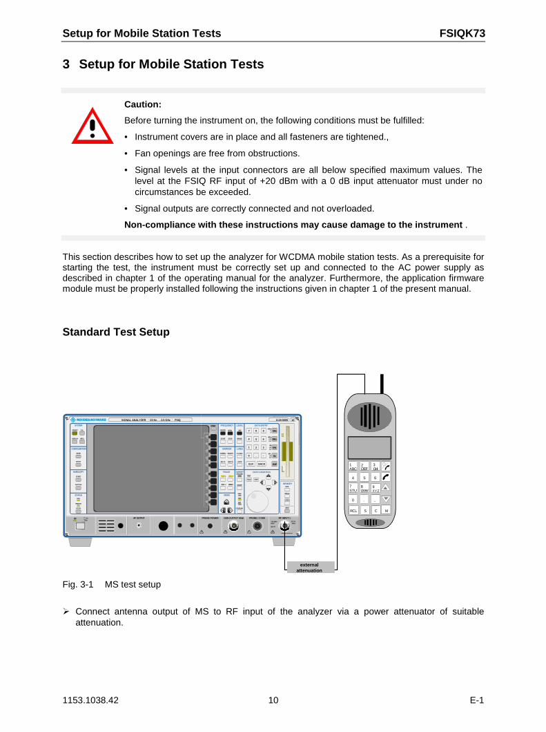
Fig. 3-1 MS test setup
Connect antenna output of MS to RF input of the analyzer via a power attenuator of suitableattenuation.
FSIQK73 Setup for Mobile Station Tests
1153.1038.42 11 E-1
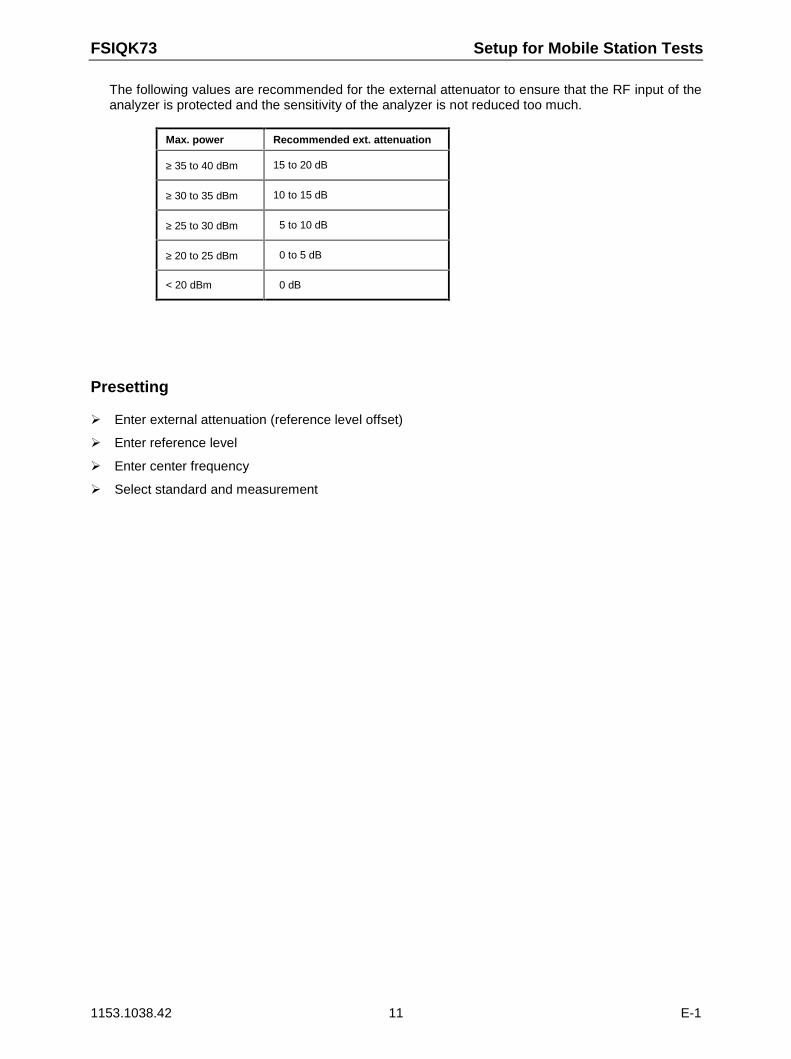
The following values are recommended for the external attenuator to ensure that the RF input of theanalyzer is protected and the sensitivity of the analyzer is not reduced too much.
Max. power Recommended ext. attenuation
≥ 35 to 40 dBm 15 to 20 dB
≥ 30 to 35 dBm 10 to 15 dB
≥ 25 to 30 dBm 5 to 10 dB
≥ 20 to 25 dBm 0 to 5 dB
< 20 dBm 0 dB
Presetting
Enter external attenuation (reference level offset)
Enter reference level
Enter center frequency
Select standard and measurement
Channel Configuration FSIQK73
1153.1038.42 12 E-1
4 Channel Configuration
The possible channel configurations for the mobile station signal are limited by 3GPP. Only two differentconfigurations are permissible according to the specification. For this reason, the FSIQK73 checks forthese two channel configurations only once during the automatic channel search. Therefore, channelswhose parameters do not correspond to one of these configurations are not automatically detected asactive channels.
The two possible channel configurations are summarized below:
Table 4-1 Channel configuration 1: DPCCH and 1 DPDCH
Channel type Number ofchannels
Symbol rate Spreading code(s) Mapping tocomponent
DPCCH 1 15 ksps 0 Q
DPDCH 1 15 ksps – 960 ksps [Spreading-Faktor / 4] I
Table 4-2 Channel configuration 2: DPCCH to 6 DPDCH
Channel type Number ofchannels
Symbol rate Spreading code(s) Mapping tocomponent
DPCCH 1 15 ksps 0 Q
DPDCH 1 960 ksps 1 I
DPDCH 1 960 ksps 1 Q
DPDCH 1 960 ksps 3 I
DPDCH 1 960 ksps 3 Q
DPDCH 1 960 ksps 2 I
DPDCH 1 960 ksps 2 Q
FSIQK73 Menu Overview
1153.1038.42 13 E-1
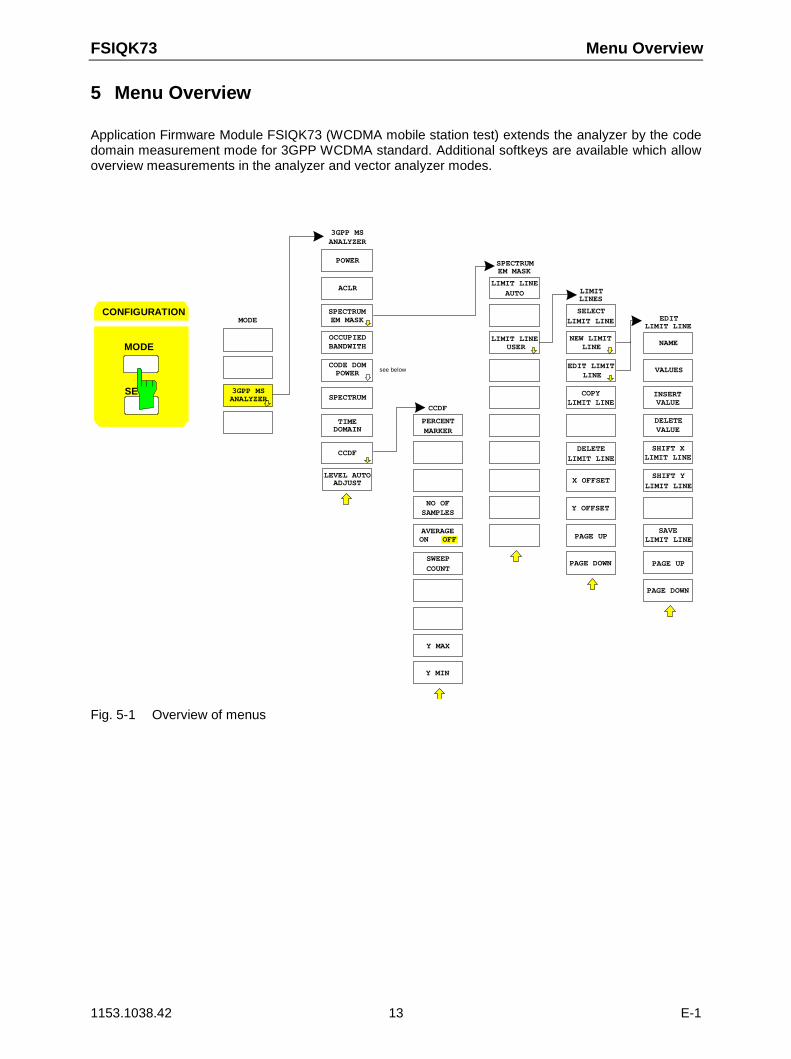
5 Menu Overview
Application Firmware Module FSIQK73 (WCDMA mobile station test) extends the analyzer by the codedomain measurement mode for 3GPP WCDMA standard. Additional softkeys are available which allowoverview measurements in the analyzer and vector analyzer modes.
MODE
MODE
SE
CONFIGURATION
3GPP MSANALYZER
3GPP MSANALYZER
CODE DOM
SPECTRUM
TIME
OCCUPIEDBANDWITH
ACLR
POWER
POWER
DOMAIN
LEVEL AUTOADJUST
CCDF
SPECTRUMEM MASK
PERCENT
NO OFSAMPLES
CCDF
AVERAGE
MARKER
Y MAX
Y MIN
ON OFF
COUNTSWEEP
see below
LIMIT LINE
SPECTRUM
USER
EM MASK
AUTO
SELECT
COPYLIMIT LINE
LIMIT
EDIT LIMIT
LINES
LINE
LIMIT LINE
NEW LIMIT
PAGE UP
PAGE DOWN
X OFFSET
LIMIT LINEDELETE
Y OFFSET
LIMIT LINE
LINE
NAME
INSERTVALUE
EDIT
DELETE
LIMIT LINE
VALUES
PAGE UP
PAGE DOWN
VALUE
LIMIT LINE
SHIFT Y
SAVE
LIMIT LINESHIFT X
LIMIT LINE
Fig. 5-1 Overview of menus
Menu Overview FSIQK73
1153.1038.42 14 E-1
MARKER
MARKER
-> DPCCHMARKER
CODE CHAN
CODE CHAN
CODE PWR
CODE PWRABSOLUTE
CODE PWROVERVIEW
CODE PWRZOOM
MODULATIONACCURACY
PEAK CODEDOMAIN ERR
SELECTPCDE SF
RESULTDISPLY
CHANNEL
SYMBOLCONST DIAG
SYMBOLEVM
BITSTREAM
RESULTDISPLAY
RELATIVE TABLE
SELECT SELECT
CODE NO. CODE NO.
SELECT SELECT
SLOT SLOTSCRAMBLING
CODE
CENTERFREQUENCY
MEAS
SIDE BANDNORM INV
SETTINGS
REF LEVEL
REF LEVELOFFSET
RF ATTENMANUAL
ATTEN AUTOLOW NOISE
MIXERLEVEL
ATTEN AUTONORMAL
REF LEVEL
ATTEN AUTOLOW DIST
CONTINUOUS
SWEEP
SINGLESWEEP
MEASSETTINGS
CODE DOMPOWER
MARKER
REF LEVEL
CDP AUTOADJUST
LEVEL AUTOADJUST
RESULTDISPLAY
CODE CHANCONFIG
CONFIG
CODE CHAN
AUTOSEARCH
PREDEFINED
PAGE UP
PAGE DOWN
EDIT CHANCONF TABLE
DEL CHANCONF TABLE
COPY CHANCONF TABLE
MODE
MODE
SE
CONFIGURATION
3GPP MSANALYZER
3GPP MSANALYZER
CODE DOM
SPECTRUM
TIME
OCCUPIEDBANDWITH
ACLR
POWER
POWER
DOMAIN
LEVEL AUTOADJUST
CCDF
SPECTRUMEM MASK
CHAN TABLE
EDIT CHANCONF TABLE
VALUES
HEADER
CHAN TABLE
SAVE TABLE
POWERVS SLOT
RESULTSUMMARY
SELECTI Q
SELECTI Q
NORMALIZEON OFF
SCR TYPESHRT
EXT TRIGOFFSET
TRIGGERINT EXT
INACT CHANTHRESHOLD
LONG
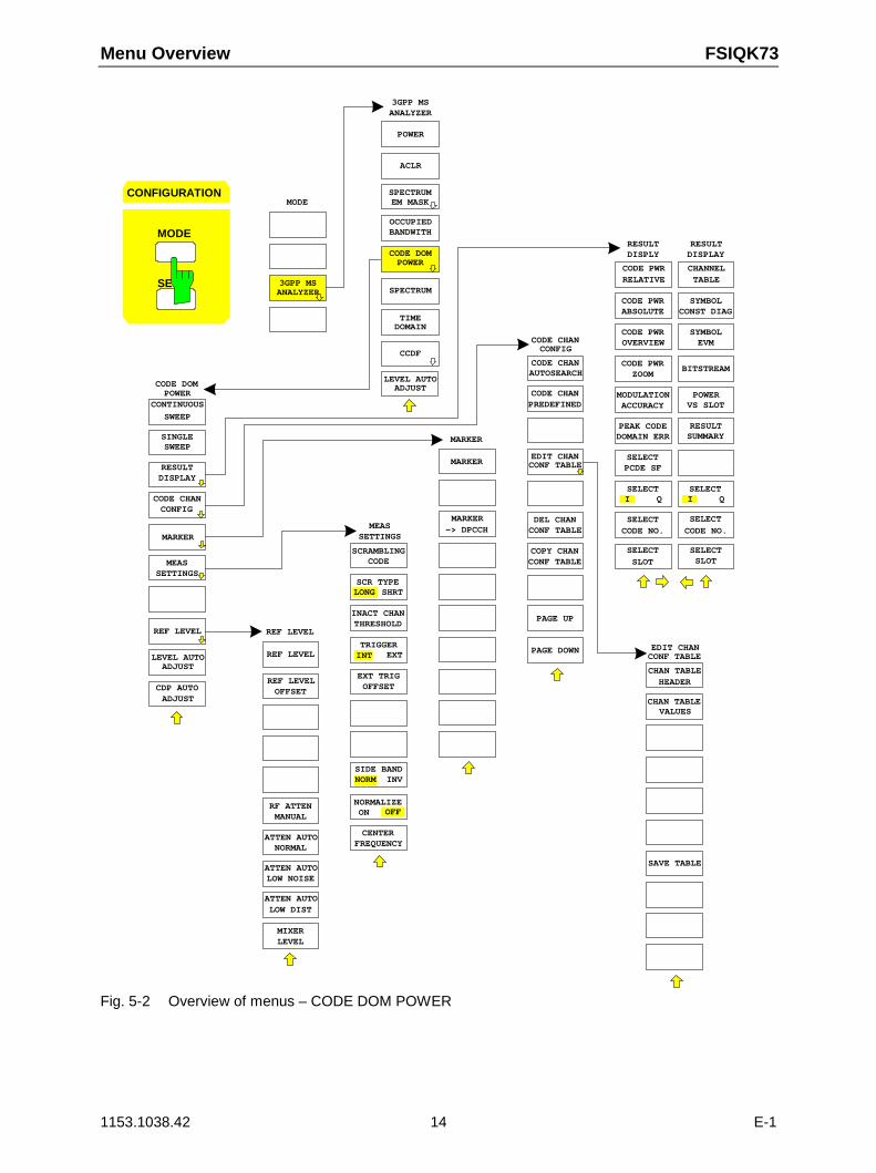
Fig. 5-2 Overview of menus – CODE DOM POWER
FSIQK73 WCDMA Measurements
1153.1038.42 15 E-1
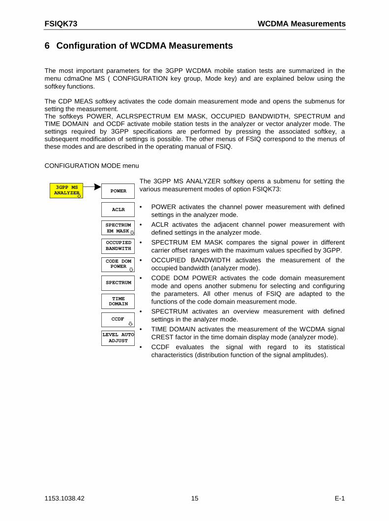
6 Configuration of WCDMA Measurements
The most important parameters for the 3GPP WCDMA mobile station tests are summarized in themenu cdmaOne MS ( CONFIGURATION key group, Mode key) and are explained below using thesoftkey functions.
The CDP MEAS softkey activates the code domain measurement mode and opens the submenus forsetting the measurement.The softkeys POWER, ACLRSPECTRUM EM MASK, OCCUPIED BANDWIDTH, SPECTRUM andTIME DOMAIN and OCDF activate mobile station tests in the analyzer or vector analyzer mode. Thesettings required by 3GPP specifications are performed by pressing the associated softkey, asubsequent modification of settings is possible. The other menus of FSIQ correspond to the menus ofthese modes and are described in the operating manual of FSIQ.
CONFIGURATION MODE menu
CODE DOM
SPECTRUM
TIME
ACLR
POWER
POWER
DOMAIN
3GPP MSANALYZER
OCCUPIEDBANDWITH
LEVEL AUTOADJUST
SPECTRUMEM MASK
CCDF
The 3GPP MS ANALYZER softkey opens a submenu for setting thevarious measurement modes of option FSIQK73:
• POWER activates the channel power measurement with definedsettings in the analyzer mode.
• ACLR activates the adjacent channel power measurement withdefined settings in the analyzer mode.
• SPECTRUM EM MASK compares the signal power in differentcarrier offset ranges with the maximum values specified by 3GPP.
• OCCUPIED BANDWIDTH activates the measurement of theoccupied bandwidth (analyzer mode).
• CODE DOM POWER activates the code domain measurementmode and opens another submenu for selecting and configuringthe parameters. All other menus of FSIQ are adapted to thefunctions of the code domain measurement mode.
• SPECTRUM activates an overview measurement with definedsettings in the analyzer mode.
• TIME DOMAIN activates the measurement of the WCDMA signalCREST factor in the time domain display mode (analyzer mode).
• CCDF evaluates the signal with regard to its statisticalcharacteristics (distribution function of the signal amplitudes).
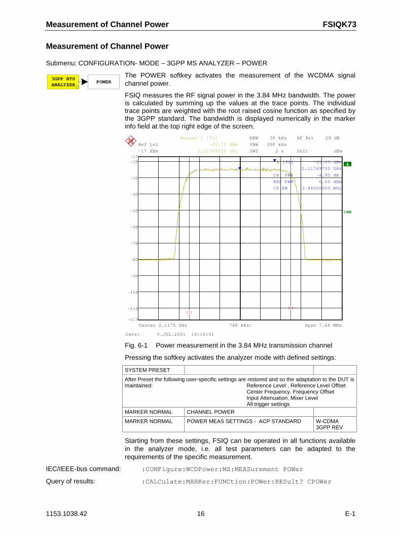
Measurement of Channel Power FSIQK73
1153.1038.42 16 E-1
Measurement of Channel Power
Submenu: CONFIGURATION- MODE – 3GPP MS ANALYZER – POWER
3GPP BTSANALYZER
POWERThe POWER softkey activates the measurement of the WCDMA signalchannel power.
FSIQ measures the RF signal power in the 3.84 MHz bandwidth. The poweris calculated by summing up the values at the trace points. The individualtrace points are weighted with the root raised cosine function as specified bythe 3GPP standard. The bandwidth is displayed numerically in the markerinfo field at the top right edge of the screen.
A
RBW 30 kHz
VBW 300 kHz
SWT 2 s
RF Att 20 dB
1RM
Unit dBm
Ref Lvl
-17 dBm
Ref Lvl
-17 dBm
768 kHz/Center 2.1175 GHz Span 7.68 MHz
-110
-100
-90
-80
-70
-60
-50
-40
-30
-20
-117
-17
1
Marker 1 [T1]
-25.11 dBm
2.11749750 GHz
1 [T1] -25.11 dBm
2.11749750 GHz
CH PWR -4.95 dB
REF PWR 0.00 dBm
CH BW 3.84000000 MHz
C0C0
Date: 5.JUL.2001 10:16:41
Fig. 6-1 Power measurement in the 3.84 MHz transmission channel
Pressing the softkey activates the analyzer mode with defined settings:
SYSTEM PRESET
After Preset the following user-specific settings are restored and so the adaptation to the DUT ismaintained: Reference Level , Reference Level Offset
Center Frequency, Frequency OffsetInput Attenuation, Mixer LevelAll trigger settings
MARKER NORMAL CHANNEL POWER
MARKER NORMAL POWER MEAS SETTINGS - ACP STANDARD W-CDMA3GPP REV
Starting from these settings, FSIQ can be operated in all functions availablein the analyzer mode, i.e. all test parameters can be adapted to therequirements of the specific measurement.
IEC/IEEE-bus command: :CONFigure:WCDPower:MS:MEASurement POWer
Query of results: :CALCulate:MARKer:FUNCtion:POWer:RESult? CPOWer
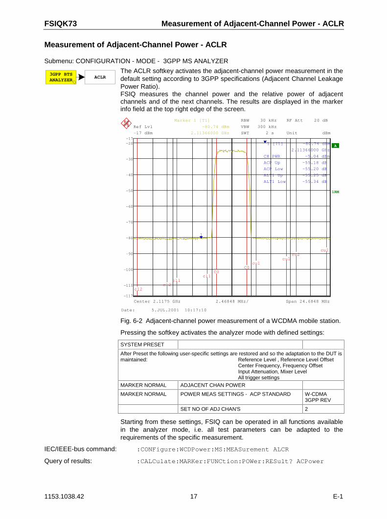
FSIQK73 Measurement of Adjacent-Channel Power - ACLR
1153.1038.42 17 E-1
Measurement of Adjacent-Channel Power - ACLR
Submenu: CONFIGURATION - MODE - 3GPP MS ANALYZER
3GPP BTSANALYZER
ACLRThe ACLR softkey activates the adjacent-channel power measurement in thedefault setting according to 3GPP specifications (Adjacent Channel LeakagePower Ratio). FSIQ measures the channel power and the relative power of adjacentchannels and of the next channels. The results are displayed in the markerinfo field at the top right edge of the screen.
RBW 30 kHz
VBW 300 kHz
SWT 2 s
RF Att 20 dB
A
1RM
Unit dBm
Ref Lvl
-17 dBm
Ref Lvl
-17 dBm
2.46848 MHz/Center 2.1175 GHz Span 24.6848 MHz
-110
-100
-90
-80
-70
-60
-50
-40
-30
-20
-117
-17
1
Marker 1 [T1]
-80.74 dBm
2.11366000 GHz
1 [T1] -80.74 dBm
2.11366000 GHz
CH PWR -5.04 dBm
ACP Up -55.18 dB
ACP Low -55.20 dB
ALT1 Up -55.25 dB
ALT1 Low -55.34 dB
cl2cl2
cl1cl1
C0C0
cu1cu1
cu2cu2
Date: 5.JUL.2001 10:17:10
Fig. 6-2 Adjacent-channel power measurement of a WCDMA mobile station.
Pressing the softkey activates the analyzer mode with defined settings:
SYSTEM PRESET
After Preset the following user-specific settings are restored and so the adaptation to the DUT ismaintained: Reference Level , Reference Level Offset
Center Frequency, Frequency OffsetInput Attenuation, Mixer LevelAll trigger settings
MARKER NORMAL ADJACENT CHAN POWER
MARKER NORMAL POWER MEAS SETTINGS - ACP STANDARD W-CDMA3GPP REV
SET NO OF ADJ CHAN’S 2
Starting from these settings, FSIQ can be operated in all functions availablein the analyzer mode, i.e. all test parameters can be adapted to therequirements of the specific measurement.
IEC/IEEE-bus command: :CONFigure:WCDPower:MS:MEASurement ALCR
Query of results: :CALCulate:MARKer:FUNCtion:POWer:RESult? ACPower
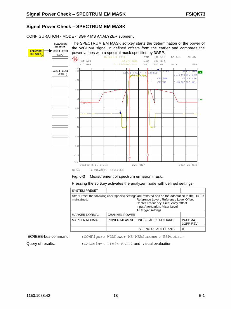
Signal Power Check – SPECTRUM EM MASK FSIQK73
1153.1038.42 18 E-1
Signal Power Check – SPECTRUM EM MASK
CONFIGURATION - MODE - 3GPP MS ANALYZER submenu
SPECTRUM LIMIT LINE
SPECTRUM
USER
EM MASK
AUTO
LIMIT LINE
EM MASK
The SPECTRUM EM MASK softkey starts the determination of the power ofthe WCDMA signal in defined offsets from the carrier and compares thepower values with a spectral mask specified by 3GPP.
RBW 30 kHz
VBW 300 kHz
SWT 500 ms
RF Att 20 dB
A
1RM
Unit dBm
Ref Lvl
-17 dBm
Ref Lvl
-17 dBm
2.5 MHz/Center 2.1175 GHz Span 25 MHz
-110
-100
-90
-80
-70
-60
-50
-40
-30
-20
-117
-17
1
Marker 1 [T1]
-65.77 dBm
2.11366000 GHz
1 [T1] -65.77 dBm
2.11366000 GHz
CH PWR -5.04 dBm
CH BW 3.84000000 MHz
LIMIT CHECK : PASSED
C0C0
3gpp-up
Date: 5.JUL.2001 10:17:50
Fig. 6-3 Measurement of spectrum emission mask.
Pressing the softkey activates the analyzer mode with defined settings:
SYSTEM PRESET
After Preset the following user-specific settings are restored and so the adaptation to the DUT ismaintained: Reference Level , Reference Level Offset
Center Frequency, Frequency OffsetInput Attenuation, Mixer LevelAll trigger settings
MARKER NORMAL CHANNEL POWER
MARKER NORMAL POWER MEAS SETTINGS - ACP STANDARD W-CDMA3GPP REV
SET NO OF ADJ CHAN’S 0
IEC/IEEE-bus command: :CONFigure:WCDPower:MS:MEASurement ESPectrum
Query of results: :CALCulate:LIMit:FAIL? and visual evaluation
FSIQK73 Signal Power Check – SPECTRUM EM MASK
1153.1038.42 19 E-1
LIMIT LINEAUTO
The LIMIT LINE AUTO softkey automatically selects the limit line to bechecked according to power determined in the useful channel. If themeasurement is carried out in CONTINUOUS SWEEP and the channelpower changes from sweep to sweep, this can result in the limit linebeing continuously redrawn. The softkey is activated when the spectrum emission maskmeasurement is entered. IEC/IEEE-bus command: :CALC:LIM:ESP:MODE AUTO
LIMIT LINEUSER
The LIMIT LINE USER softkey activates the input of user-defined limitlines. The softkey opens the menus of the limit line editor that are knownfrom the basic unit. The limit lines created by the user are included inthe table for LIMIT LINE MANUAL.
The following limit line settings are useful for mobile station tests:Trace 1, Domain Frequency, X-Scaling relative, Y-Scaling absolute,Spacing linear, Unit dBm
In contrast to the predefined limit lines supplied with the FSIQ whichcorrespond to the standard specifications, the user-defined limit line canbe specified for the entire frequency range (±12.5 MHz from carrier)either relatively (referred to the channel power) or absolutely.
IEC/IEEE-bus command: see Table of Softkeys with Assignment ofIEC/IEEE Commands
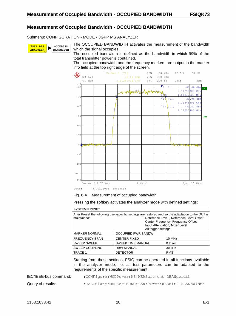
Measurement of Occupied Bandwidth - OCCUPIED BANDWIDTH FSIQK73
1153.1038.42 20 E-1
Measurement of Occupied Bandwidth - OCCUPIED BANDWIDTH
Submenu: CONFIGURATION - MODE - 3GPP MS ANALYZER
3GPP BTSANALYZER
OCCUPIEDBANDWIDTH
The OCCUPIED BANDWIDTH activates the measurement of the bandwidthwhich the signal occupies.The occupied bandwidth is defined as the bandwidth in which 99% of thetotal transmitter power is contained.The occupied bandwidth and the frequency markers are output in the markerinfo field at the top right edge of the screen.
RBW 30 kHz
VBW 300 kHz
SWT 200 ms
RF Att 20 dB
A
1RM
Unit dBm
Ref Lvl
-17 dBm
Ref Lvl
-17 dBm
1 MHz/Center 2.1175 GHz Span 10 MHz
-110
-100
-90
-80
-70
-60
-50
-40
-30
-20
-117
-17
1
T1 T2
Marker 1 [T1]
-81.68 dBm
2.11250000 GHz
1 [T1] -81.68 dBm
2.11250000 GHz
OPB 4.06813627 MHz
T1 [T1] -31.98 dBm
2.11546593 GHz
T2 [T1] -31.42 dBm
2.11953407 GHz
Date: 5.JUL.2001 10:18:18
Fig. 6-4 Measurement of occupied bandwidth.
Pressing the softkey activates the analyzer mode with defined settings:
SYSTEM PRESET
After Preset the following user-specific settings are restored and so the adaptation to the DUT ismaintained: Reference Level , Reference Level Offset
Center Frequency, Frequency OffsetInput Attenuation, Mixer LevelAll trigger settings
MARKER NORMAL OCCUPIED PWR BANDW
FREQUENCY SPAN CENTER FIXED 10 MHz
SWEEP SWEEP SWEEP TIME MANUAL 0.2 sec
SWEEP COUPLING RBW MANUAL 30 kHz
TRACE 1 DETECTOR RMS
Starting from these settings, FSIQ can be operated in all functions availablein the analyzer mode, i.e. all test parameters can be adapted to therequirements of the specific measurement.
IEC/IEEE-bus command: :CONFigure:WCDPower:MS:MEASurement OBANdwidth
Query of results: :CALCulate:MARKer:FUNCtion:POWer:RESult? OBANdwidth
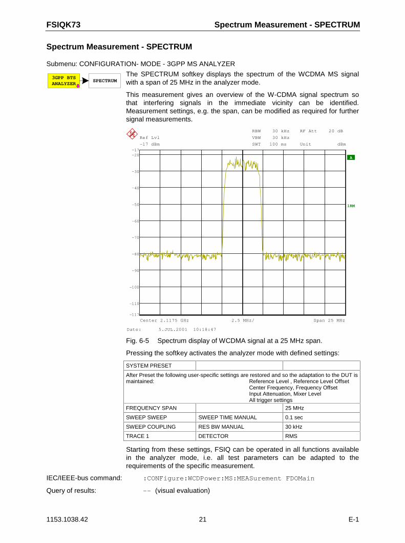
FSIQK73 Spectrum Measurement - SPECTRUM
1153.1038.42 21 E-1
Spectrum Measurement - SPECTRUM
Submenu: CONFIGURATION- MODE - 3GPP MS ANALYZER
3GPP BTSANALYZER
SPECTRUMThe SPECTRUM softkey displays the spectrum of the WCDMA MS signalwith a span of 25 MHz in the analyzer mode.
This measurement gives an overview of the W-CDMA signal spectrum sothat interfering signals in the immediate vicinity can be identified.Measurement settings, e.g. the span, can be modified as required for furthersignal measurements.
RBW 30 kHz
VBW 30 kHz
SWT 100 ms
RF Att 20 dB
A
1RM
Unit dBm
Ref Lvl
-17 dBm
Ref Lvl
-17 dBm
2.5 MHz/Center 2.1175 GHz Span 25 MHz
-110
-100
-90
-80
-70
-60
-50
-40
-30
-20
-117
-17
Date: 5.JUL.2001 10:18:47
Fig. 6-5 Spectrum display of WCDMA signal at a 25 MHz span.
Pressing the softkey activates the analyzer mode with defined settings:
SYSTEM PRESET
After Preset the following user-specific settings are restored and so the adaptation to the DUT ismaintained: Reference Level , Reference Level Offset
Center Frequency, Frequency OffsetInput Attenuation, Mixer LevelAll trigger settings
FREQUENCY SPAN 25 MHz
SWEEP SWEEP SWEEP TIME MANUAL 0.1 sec
SWEEP COUPLING RES BW MANUAL 30 kHz
TRACE 1 DETECTOR RMS
Starting from these settings, FSIQ can be operated in all functions availablein the analyzer mode, i.e. all test parameters can be adapted to therequirements of the specific measurement.
IEC/IEEE-bus command: :CONFigure:WCDPower:MS:MEASurement FDOMain
Query of results: -- (visual evaluation)
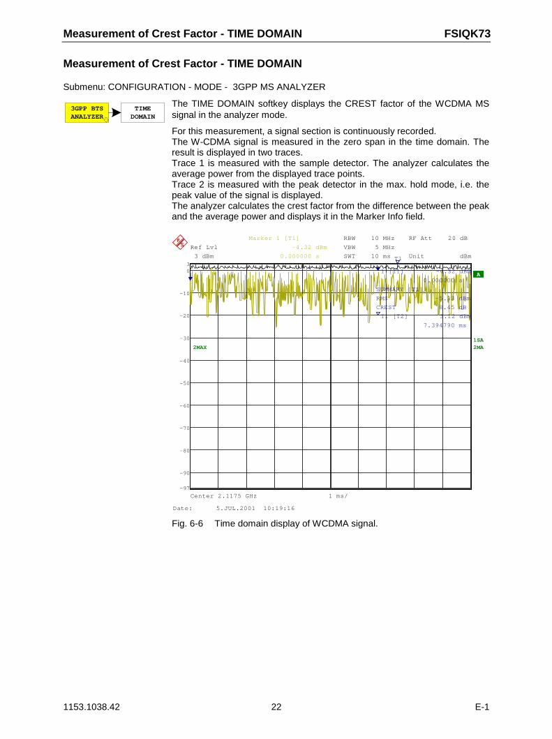
Measurement of Crest Factor - TIME DOMAIN FSIQK73
1153.1038.42 22 E-1
Measurement of Crest Factor - TIME DOMAIN
Submenu: CONFIGURATION - MODE - 3GPP MS ANALYZER
3GPP BTSANALYZER
TIMEDOMAIN
The TIME DOMAIN softkey displays the CREST factor of the WCDMA MSsignal in the analyzer mode.
For this measurement, a signal section is continuously recorded.The W-CDMA signal is measured in the zero span in the time domain. Theresult is displayed in two traces.Trace 1 is measured with the sample detector. The analyzer calculates theaverage power from the displayed trace points.Trace 2 is measured with the peak detector in the max. hold mode, i.e. thepeak value of the signal is displayed.The analyzer calculates the crest factor from the difference between the peakand the average power and displays it in the Marker Info field.
2MAX
RBW 10 MHz
VBW 5 MHz
SWT 10 ms
RF Att 20 dB
A
1SA2MA
Unit dBm
2MA
Ref Lvl
3 dBm
Ref Lvl
3 dBm
Center 2.1175 GHz 1 ms/
-90
-80
-70
-60
-50
-40
-30
-20
-10
0
-97
3
1
T1
Marker 1 [T1]
-4.32 dBm
0.000000 s
1 [T1] -4.32 dBm
0.000000 s
SUMMARY [T1]
RMS -5.33 dBm
CREST 8.45 dB
T1 [T2] 3.12 dBm
7.394790 ms
Date: 5.JUL.2001 10:19:16
Fig. 6-6 Time domain display of WCDMA signal.
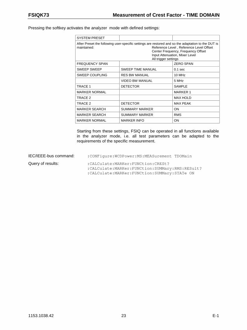
FSIQK73 Measurement of Crest Factor - TIME DOMAIN
1153.1038.42 23 E-1
Pressing the softkey activates the analyzer mode with defined settings:
SYSTEM PRESET
After Preset the following user-specific settings are restored and so the adaptation to the DUT ismaintained: Reference Level , Reference Level Offset
Center Frequency, Frequency OffsetInput Attenuation, Mixer LevelAll trigger settings
FREQUENCY SPAN ZERO SPAN
SWEEP SWEEP SWEEP TIME MANUAL 0.1 sec
SWEEP COUPLING RES BW MANUAL 10 MHz
VIDEO BW MANUAL 5 MHz
TRACE 1 DETECTOR SAMPLE
MARKER NORMAL MARKER 1
TRACE 2 MAX HOLD
TRACE 2 DETECTOR MAX PEAK
MARKER SEARCH SUMMARY MARKER ON
MARKER SEARCH SUMMARY MARKER RMS
MARKER NORMAL MARKER INFO ON
Starting from these settings, FSIQ can be operated in all functions availablein the analyzer mode, i.e. all test parameters can be adapted to therequirements of the specific measurement.
IEC/IEEE-bus command: :CONFigure:WCDPower:MS:MEASurement TDOMain
Query of results: :CALCulate:MARKer:FUNCtion:CRESt?:CALCulate:MARKer:FUNCtion:SUMMary:RMS:RESult?:CALCulate:MARKer:FUNCtion:SUMMary:STATe ON
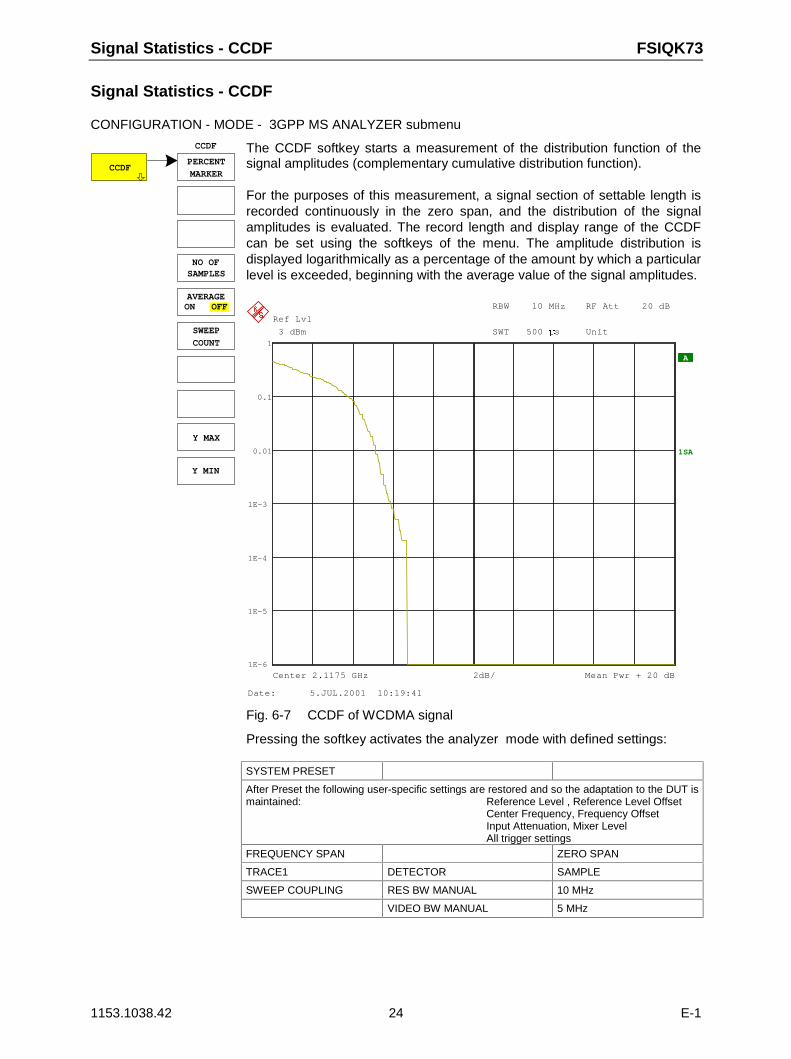
Signal Statistics - CCDF FSIQK73
1153.1038.42 24 E-1
Signal Statistics - CCDF
CONFIGURATION - MODE - 3GPP MS ANALYZER submenu
CCDFPERCENT
NO OFSAMPLES
CCDF
AVERAGE
MARKER
Y MAX
Y MIN
ON OFF
COUNTSWEEP
The CCDF softkey starts a measurement of the distribution function of thesignal amplitudes (complementary cumulative distribution function).
For the purposes of this measurement, a signal section of settable length isrecorded continuously in the zero span, and the distribution of the signalamplitudes is evaluated. The record length and display range of the CCDFcan be set using the softkeys of the menu. The amplitude distribution isdisplayed logarithmically as a percentage of the amount by which a particularlevel is exceeded, beginning with the average value of the signal amplitudes.
RBW 10 MHz
SWT 500 Ës
RF Att 20 dB
A
1SA
Unit
Ref Lvl
3 dBm
Ref Lvl
3 dBm
Center 2.1175 GHz Mean Pwr + 20 dB2dB/
0.1
0.01
1E-3
1E-4
1E-5
1E-6
1
Date: 5.JUL.2001 10:19:41
Fig. 6-7 CCDF of WCDMA signal
Pressing the softkey activates the analyzer mode with defined settings:
SYSTEM PRESET
After Preset the following user-specific settings are restored and so the adaptation to the DUT ismaintained: Reference Level , Reference Level Offset
Center Frequency, Frequency OffsetInput Attenuation, Mixer LevelAll trigger settings
FREQUENCY SPAN ZERO SPAN
TRACE1 DETECTOR SAMPLE
SWEEP COUPLING RES BW MANUAL 10 MHz
VIDEO BW MANUAL 5 MHz
FSIQK73 Signal Statistics - CCDF
1153.1038.42 25 E-1
Starting from these settings, FSIQ can be operated in all functions availablein the analyzer mode, i.e. all test parameters can be adapted to therequirements of the specific measurement.
IEC/IEEE-bus command: :CONFigure:WCDPower:MS:MEASurement CCDFor:CALCulate:STATistics:MS:CCDF ON
Query of results: :CALCulate:MARKer:X?
PERCENTMARKER
The PERCENT MARKER softkey sets the marker to the specifiedpercentage of the Y axis. The step width of the marker movementdepends on the current marker value. In addition to this marker, the normal markers of the analyzer can beactivated for the display mode.
IEC/IEEE-bus command: :CALC:MARK:Y:PERC 5
NO OFSAMPLES
The NO OF SAMPLES softkey specifies the number of samples used tocreate the CCDF.
IEC/IEEE-bus command: CALC:STAT:NSAM 5000
AVERAGEON OFF
The AVERAGE ON / OFF softkey specifies whether or not the results ofcontinuous measurements (in conjunction with SWEEP COUNT) areaveraged. The default setting of the softkey is OFF.
IEC/IEEE-bus command: :DISP:TRAC1:MODE AVER | VIEW
SWEEPCOUNT
The SWEEP COUNT softkey determines the number of signal sectionsacross which averaging is carried out (in the case of AVERAGE ON).Using SWEEP COUNT >1 and AVERAGE ON, the number of samplesused to evaluate the statistical characteristics of the signal can beincreased.
IEC/IEEE-bus command: :SWE:COUN 6
Y MAX
The Y MAX softkey specifies the upper limit of the display range of theCCDF. Since probabilities are specified on the Y axis, the enterednumerical values are dimensionless. The maximum value of the softkeyis 1.
IEC/IEEE-bus command: CALC:STAT:SCAL:Y:UPP 0.01
Y MIN
The Y MIN softkey specifies the lower limit of the display range of theCCDF. The minimum value of the softkey is 1E-6.
IEC/IEEE-bus command: CALC:STAT:SCAL:Y:LOW 0.001
Code Domain Measurements on WCDMA Signals FSIQK73
1153.1038.42 26 E-1
Code Domain Measurements on WCDMA Signals
Application Firmware FSIQK73 provides the peak code domain error measurement, an EVMmeasurement of the total signal (modulation accuracy), prescribed by the 3GPP standard as well as thecode domain power measurement of assigned and unassigned codes. In addition, the symbolsdemodulated in a slot, the decided bits or the EVM symbol can be displayed for an active channel.
A signal section of approx. 20 ms is recorded for analysis and searched for the start of a WCDMAframe. If a frame start is found in the signal, the CDP analysis is performed for a complete framestarting from slot 0.
Application firmware FSIQK73 offers two different ways of representing the code domain powermeasurement:
• Representation of all code channelsOption FSIQK73 displays the power of all occupied code channels in a bargraph. Since, in theuplink, the channels are handled separately for the I and Q component, the display always appliesto one of the two components. The x axis is scaled for the highest code class or the highestspreading factor (256). Code channels with a lower spreading factor occupy correspondingly morechannels of the highest code class. The power of the code channel is always correctly measured inaccordance with the actual power of the code channel. Unused code channels are assumed tobelong to the highest code class and displayed accordingly. The displayed power of an unusedcode channel therefore corresponds to the power of a channel with the spreading factor 256 at therespective code position.To simplify identification, used and unused channels are displayed in different colours. Usedchannels are yellow, unused channels are blue.The measured power always refers to one slot. The start of slot 0 coincides with the beginning ofthe analyzed WCDMA frame.
• Representation of channel power versus slots of a WCDMA signal frame
In this case the power of a selectable code channel is indicated versus a frame. The power isalways measured within one slot of the selected channel. The start of slot 0 coincides with thebeginning of the analyzed WCDMA frame.
The measurements symbol constellation, symbol EVM and bit stream are each referred to one slot ofthe selected channel.The modulation accuracy and peak code domain error measurements are always referred to the totalsignal.
For code domain power (CDP) measurements, the display is operated in the SPLIT SCREEN mode. Inthe upper section of the display, only CDP representations are permissible; in the lower section of thedisplay, all other representations are permissible. An exception is the CDP OVERVIEW display mode inwhich CDP representations appear in both sections.
For code domain power measurements, the FSIQK73 expects that the Dedicated Physical CommonControl Channel (DPCCH) is contained in the signal to be measured.There are two modes for the CDP analysis. In the CODE CHAN AUTOSEARCH mode, FSIQK73performs an automatic search for active channels in the whole code domain. The channel search isbased on the power of the channels and on a signal/noise ratio that should not be exceeded within thechannel. In the CODE CHAN PREDEFINED mode, the user can define the active channels contained inthe signal via tables that can be selected and edited.
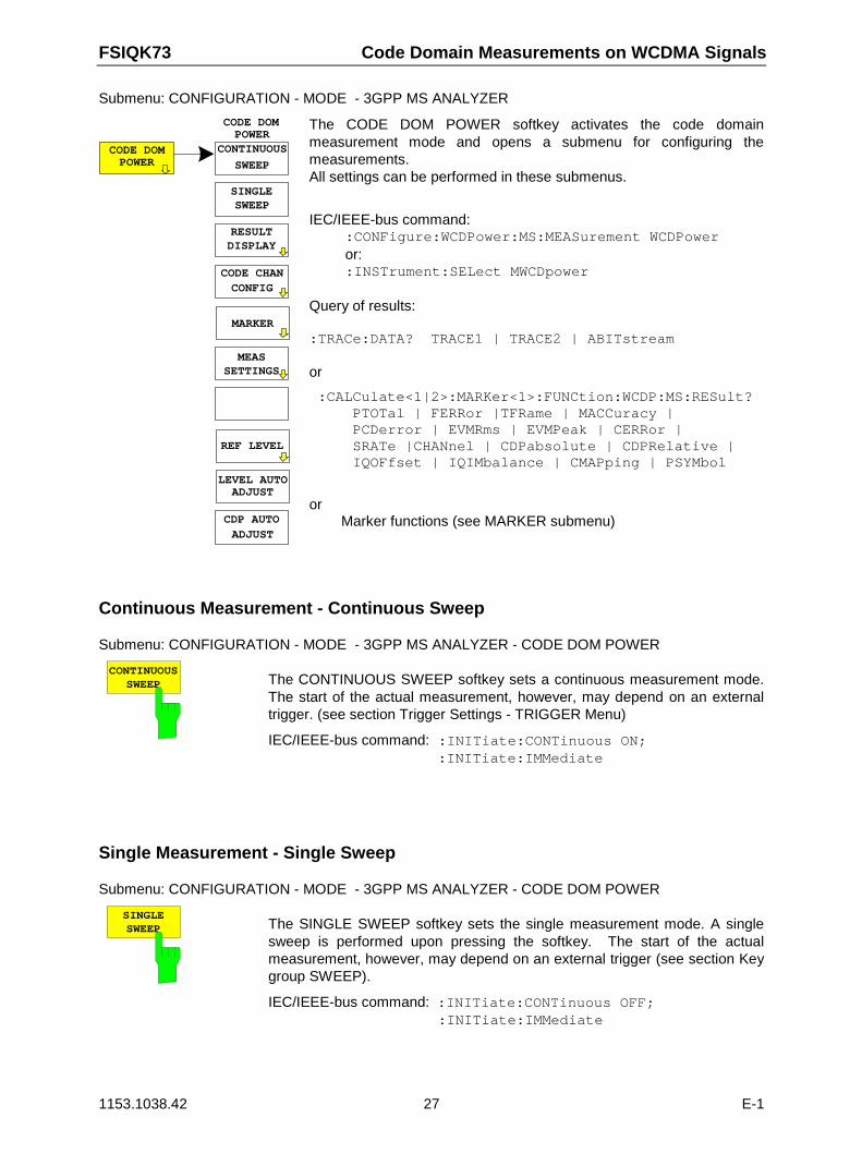
FSIQK73 Code Domain Measurements on WCDMA Signals
1153.1038.42 27 E-1
Submenu: CONFIGURATION - MODE - 3GPP MS ANALYZER
CONTINUOUS
SWEEP
SINGLESWEEP
MEASSETTINGS
CODE DOMPOWER
MARKER
RESULTDISPLAY
CODE CHANCONFIG
REF LEVEL
LEVEL AUTOADJUST
CDP AUTOADJUST
CODE DOMPOWER
The CODE DOM POWER softkey activates the code domainmeasurement mode and opens a submenu for configuring themeasurements.All settings can be performed in these submenus.
IEC/IEEE-bus command::CONFigure:WCDPower:MS:MEASurement WCDPoweror::INSTrument:SELect MWCDpower
Query of results:
:TRACe:DATA? TRACE1 | TRACE2 | ABITstream
or
:CALCulate<1|2>:MARKer<1>:FUNCtion:WCDP:MS:RESult? PTOTal | FERRor |TFRame | MACCuracy | PCDerror | EVMRms | EVMPeak | CERRor | SRATe |CHANnel | CDPabsolute | CDPRelative | IQOFfset | IQIMbalance | CMAPping | PSYMbol
orMarker functions (see MARKER submenu)
Continuous Measurement - Continuous Sweep
Submenu: CONFIGURATION - MODE - 3GPP MS ANALYZER - CODE DOM POWER
CONTINUOUSSWEEP The CONTINUOUS SWEEP softkey sets a continuous measurement mode.
The start of the actual measurement, however, may depend on an externaltrigger. (see section Trigger Settings - TRIGGER Menu)
IEC/IEEE-bus command: :INITiate:CONTinuous ON; :INITiate:IMMediate
Single Measurement - Single Sweep
Submenu: CONFIGURATION - MODE - 3GPP MS ANALYZER - CODE DOM POWER
SINGLESWEEP The SINGLE SWEEP softkey sets the single measurement mode. A single
sweep is performed upon pressing the softkey. The start of the actualmeasurement, however, may depend on an external trigger (see section Keygroup SWEEP).
IEC/IEEE-bus command: :INITiate:CONTinuous OFF;:INITiate:IMMediate
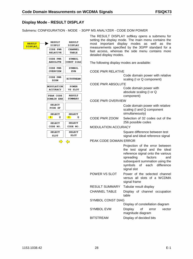
Code Domain Measurements on WCDMA Signals FSIQK73
1153.1038.42 28 E-1
Display Mode - RESULT DISPLAY
Submenu: CONFIGURATION - MODE - 3GPP MS ANALYZER - CODE DOM POWER
RESULTDISPLAY
CODE PWR
CODE PWRABSOLUTE
CODE PWROVERVIEW
CODE PWRZOOM
MODULATIONACCURACY
PEAK CODEDOMAIN ERR
SELECTPCDE SF
RESULTDISPLY
CHANNEL
SYMBOLCONST DIAG
SYMBOLEVM
BITSTREAM
RESULTDISPLAY
RELATIVE TABLE
SELECT SELECT
CODE NO. CODE NO.
SELECT SELECT
SLOT SLOT
POWERVS SLOT
RESULTSUMMARY
SELECTI Q
SELECTI Q
The RESULT DISPLAY softkey opens a submenu forsetting the display mode. The main menu contains themost important display modes as well as themeasurements specified by the 3GPP standard for afast access, whereas the side menu contains moredetailed display modes.
The following display modes are available:
CODE PWR RELATIVECode domain power with relativescaling (I or Q component)
CODE PWR ABSOLUTECode domain power withabsolute scaling (I or Qcomponent)
CODE PWR OVERVIEW
Code domain power with relativescaling (I and Q componentsimultaneously)
CODE PWR ZOOM Selection of 32 codes out of the256 possible codes
MODULATION ACCURACY
Square difference between testsignal and ideal reference signal
PEAK CODE DOMAIN ERROR
Projection of the error betweenthe test signal and the idealreference signal onto the variousspreading factors andsubsequent summation using thesymbols of each differencesignal slot
POWER VS SLOT Power of the selected channelversus all slots of a WCDMAsignal frame
RESULT SUMMARY Tabular result display
CHANNEL TABLE Display of channel occupationtable
SYMBOL CONST DIAGDisplay of constellation diagram
SYMBOL EVM Display of error vectormagnitude diagram
BITSTREAM Display of decided bits
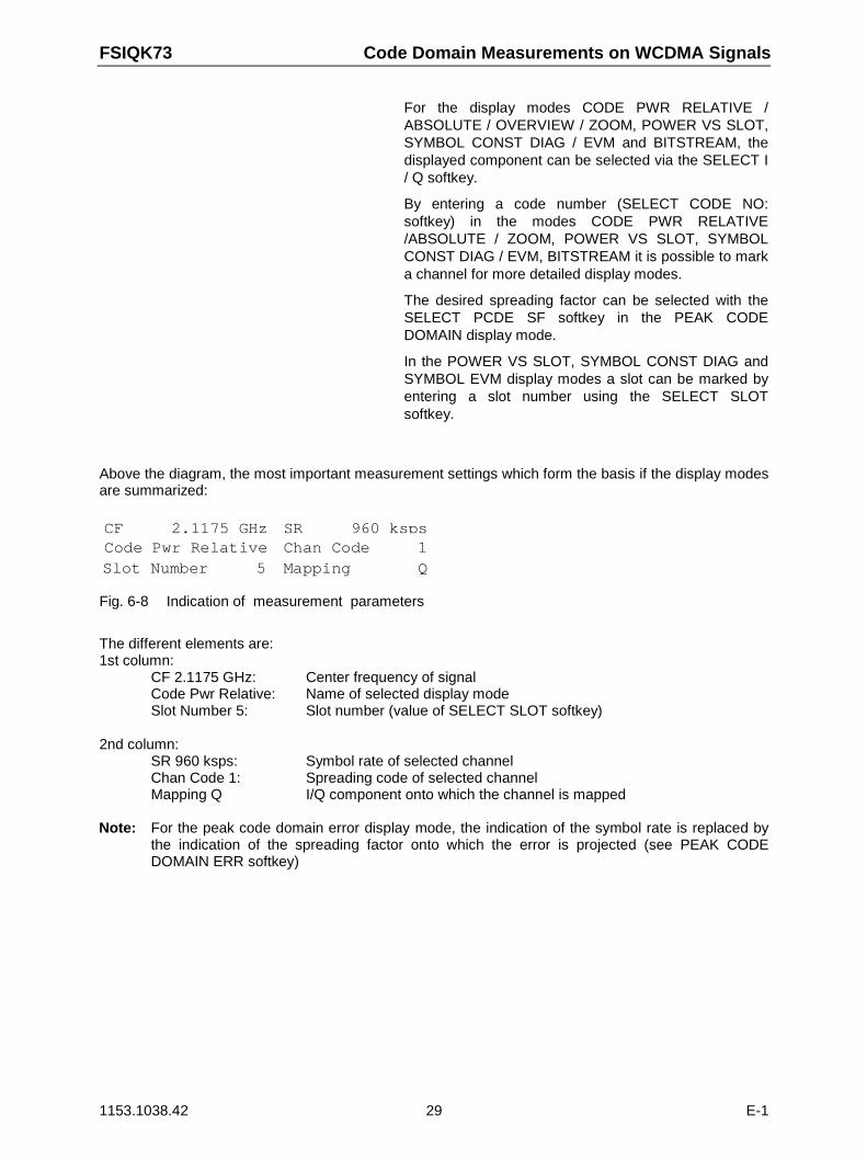
FSIQK73 Code Domain Measurements on WCDMA Signals
1153.1038.42 29 E-1
For the display modes CODE PWR RELATIVE /ABSOLUTE / OVERVIEW / ZOOM, POWER VS SLOT,SYMBOL CONST DIAG / EVM and BITSTREAM, thedisplayed component can be selected via the SELECT I/ Q softkey.
By entering a code number (SELECT CODE NO:softkey) in the modes CODE PWR RELATIVE/ABSOLUTE / ZOOM, POWER VS SLOT, SYMBOLCONST DIAG / EVM, BITSTREAM it is possible to marka channel for more detailed display modes.
The desired spreading factor can be selected with theSELECT PCDE SF softkey in the PEAK CODEDOMAIN display mode.
In the POWER VS SLOT, SYMBOL CONST DIAG andSYMBOL EVM display modes a slot can be marked byentering a slot number using the SELECT SLOTsoftkey.
Above the diagram, the most important measurement settings which form the basis if the display modesare summarized:
CF 2.1175 GHzCode Pwr RelativeCode Pwr RelativeSlot Number 5Slot Number 5
SR 960 kspsChan Code 1Chan Code 1Mapping QMapping Q
Fig. 6-8 Indication of measurement parameters
The different elements are:1st column:
CF 2.1175 GHz: Center frequency of signalCode Pwr Relative: Name of selected display modeSlot Number 5: Slot number (value of SELECT SLOT softkey)
2nd column:SR 960 ksps: Symbol rate of selected channelChan Code 1: Spreading code of selected channelMapping Q I/Q component onto which the channel is mapped
Note: For the peak code domain error display mode, the indication of the symbol rate is replaced bythe indication of the spreading factor onto which the error is projected (see PEAK CODEDOMAIN ERR softkey)
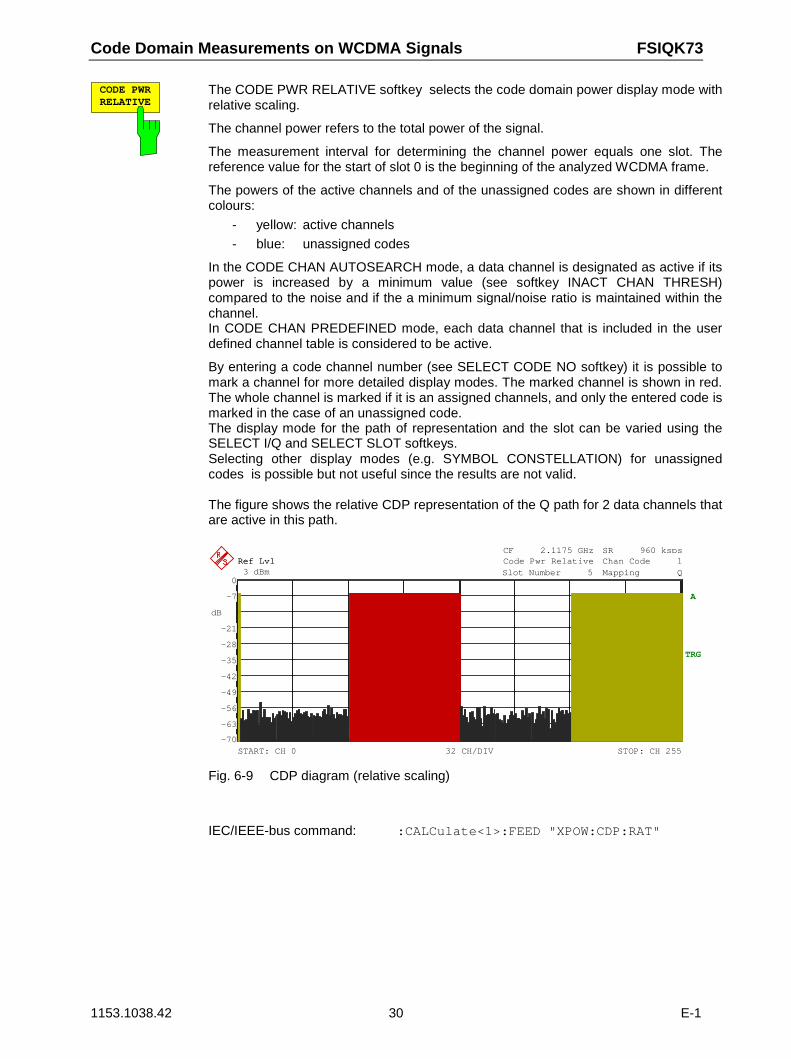
Code Domain Measurements on WCDMA Signals FSIQK73
1153.1038.42 30 E-1
CODE PWRRELATIVE
The CODE PWR RELATIVE softkey selects the code domain power display mode withrelative scaling.
The channel power refers to the total power of the signal.
The measurement interval for determining the channel power equals one slot. Thereference value for the start of slot 0 is the beginning of the analyzed WCDMA frame.
The powers of the active channels and of the unassigned codes are shown in differentcolours:
- yellow: active channels
- blue: unassigned codes
In the CODE CHAN AUTOSEARCH mode, a data channel is designated as active if itspower is increased by a minimum value (see softkey INACT CHAN THRESH)compared to the noise and if the a minimum signal/noise ratio is maintained within thechannel.In CODE CHAN PREDEFINED mode, each data channel that is included in the userdefined channel table is considered to be active.
By entering a code channel number (see SELECT CODE NO softkey) it is possible tomark a channel for more detailed display modes. The marked channel is shown in red.The whole channel is marked if it is an assigned channels, and only the entered code ismarked in the case of an unassigned code.The display mode for the path of representation and the slot can be varied using theSELECT I/Q and SELECT SLOT softkeys.Selecting other display modes (e.g. SYMBOL CONSTELLATION) for unassignedcodes is possible but not useful since the results are not valid.
The figure shows the relative CDP representation of the Q path for 2 data channels thatare active in this path.
dB
Ref Lvl3 dBmRef Lvl3 dBmRef Lvl3 dBmRef Lvl3 dBm
TRG
START: CH 0 STOP: CH 25532 CH/DIV
-28
-21
A
CF 2.1175 GHzCode Pwr RelativeCode Pwr RelativeSlot Number 5Slot Number 5
SR 960 kspsChan Code 1Chan Code 1Mapping QMapping Q
-63
-56
-49
-42
-35
-28
-21
-7
-70
0
Fig. 6-9 CDP diagram (relative scaling)
IEC/IEEE-bus command: :CALCulate<1>:FEED "XPOW:CDP:RAT"
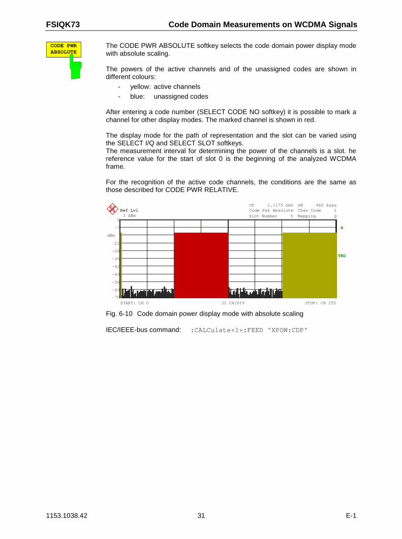
FSIQK73 Code Domain Measurements on WCDMA Signals
1153.1038.42 31 E-1
CODE PWRABSOLUTE
The CODE PWR ABSOLUTE softkey selects the code domain power display modewith absolute scaling.
The powers of the active channels and of the unassigned codes are shown indifferent colours:
- yellow: active channels
- blue: unassigned codes
After entering a code number (SELECT CODE NO softkey) it is possible to mark achannel for other display modes. The marked channel is shown in red.
The display mode for the path of representation and the slot can be varied usingthe SELECT I/Q and SELECT SLOT softkeys.The measurement interval for determining the power of the channels is a slot. hereference value for the start of slot 0 is the beginning of the analyzed WCDMAframe.
For the recognition of the active code channels, the conditions are the same asthose described for CODE PWR RELATIVE.
dBm
Ref Lvl3 dBmRef Lvl3 dBmRef Lvl3 dBmRef Lvl3 dBm
TRG
START: CH 0 STOP: CH 25532 CH/DIV
-28
-21
CF 2.1175 GHzCode Pwr AbsoluteCode Pwr AbsoluteSlot Number 5Slot Number 5
SR 960 kspsChan Code 1Chan Code 1Mapping QMapping Q
A
-63
-56
-49
-42
-35
-28
-21
-7
-70
0
Fig. 6-10 Code domain power display mode with absolute scaling
IEC/IEEE-bus command: :CALCulate<1>:FEED "XPOW:CDP"
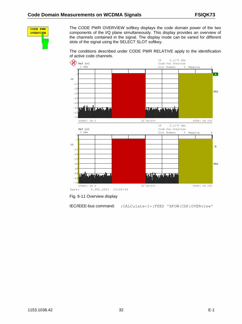
Code Domain Measurements on WCDMA Signals FSIQK73
1153.1038.42 32 E-1
CODE PWROVERVIEW
The CODE PWR OVERVIEW softkey displays the code domain power of the twocomponents of the I/Q plane simultaneously. This display provides an overview ofthe channels contained in the signal. The display mode can be varied for differentslots of the signal using the SELECT SLOT softkey.
The conditions described under CODE PWR RELATIVE apply to the identificationof active code channels.
dB
dB
Ref Lvl3 dBmRef Lvl3 dBmRef Lvl3 dBmRef Lvl3 dBm
TRG
START: CH 0 STOP: CH 25532 CH/DIV
CF 2.1175 GHzCode Pwr OverviewCode Pwr OverviewSlot Number 5Slot Number 5 Mapping IMapping I
-28
-21
A
Ref Lvl3 dBmRef Lvl3 dBmRef Lvl3 dBmRef Lvl3 dBm
TRG
START: CH 0 STOP: CH 25532 CH/DIV
CF 2.1175 GHzCode Pwr OverviewCode Pwr OverviewSlot Number 5Slot Number 5 Mapping QMapping Q
-28
-21B
-63
-56
-49
-42
-35
-28
-21
-7
-70
0
-63
-56
-49
-42
-35
-28
-21
-7
-70
0
Date: 5.JUL.2001 10:28:54
Fig. 6-11 Overview display
IEC/IEEE-bus command: :CALCulate<1>:FEED "XPOW:CDP:OVERview"
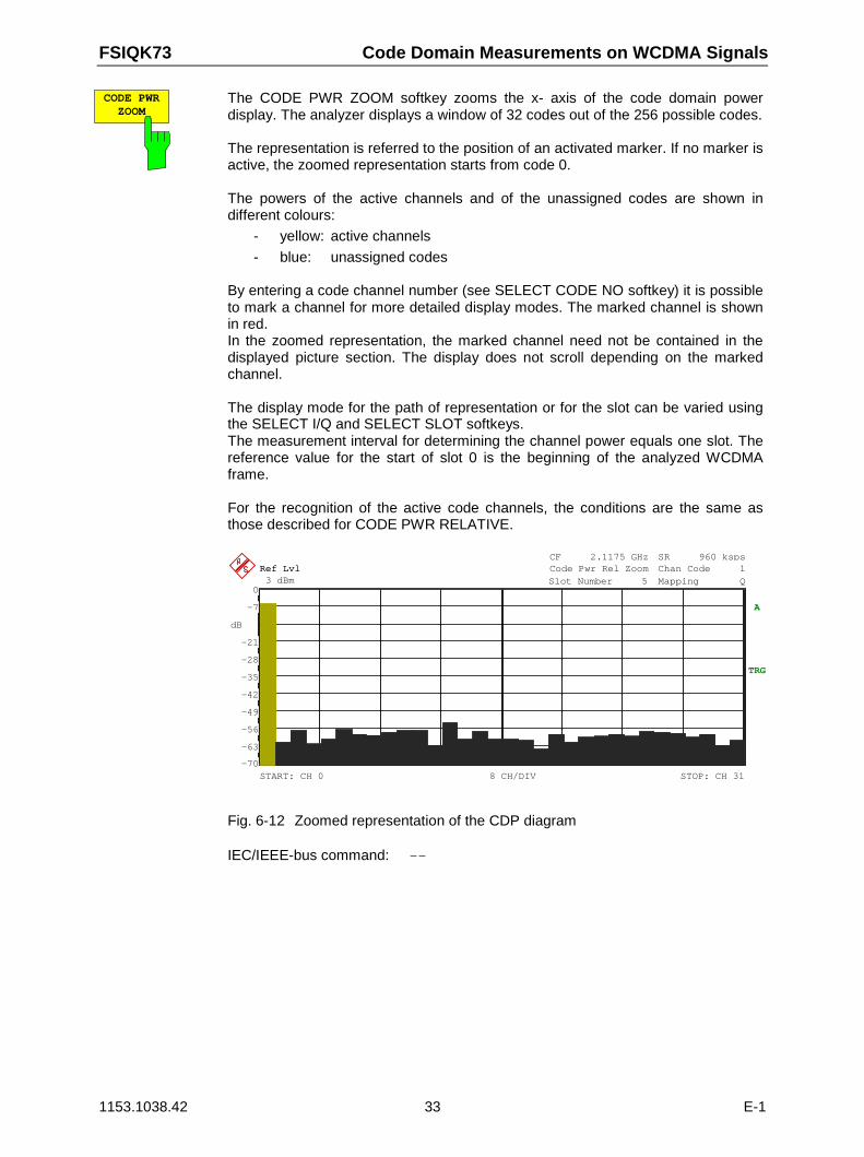
FSIQK73 Code Domain Measurements on WCDMA Signals
1153.1038.42 33 E-1
CODE PWRZOOM
The CODE PWR ZOOM softkey zooms the x- axis of the code domain powerdisplay. The analyzer displays a window of 32 codes out of the 256 possible codes.
The representation is referred to the position of an activated marker. If no marker isactive, the zoomed representation starts from code 0.
The powers of the active channels and of the unassigned codes are shown indifferent colours:
- yellow: active channels
- blue: unassigned codes
By entering a code channel number (see SELECT CODE NO softkey) it is possibleto mark a channel for more detailed display modes. The marked channel is shownin red.In the zoomed representation, the marked channel need not be contained in thedisplayed picture section. The display does not scroll depending on the markedchannel.
The display mode for the path of representation or for the slot can be varied usingthe SELECT I/Q and SELECT SLOT softkeys.The measurement interval for determining the channel power equals one slot. Thereference value for the start of slot 0 is the beginning of the analyzed WCDMAframe.
For the recognition of the active code channels, the conditions are the same asthose described for CODE PWR RELATIVE.
dB
Ref Lvl3 dBmRef Lvl3 dBmRef Lvl3 dBmRef Lvl3 dBm
TRG
START: CH 0 STOP: CH 318 CH/DIV
CF 2.1175 GHzCode Pwr Rel ZoomCode Pwr Rel ZoomSlot Number 5Slot Number 5
SR 960 kspsChan Code 1Chan Code 1Mapping QMapping Q
-28
-21
A
-63
-56
-49
-42
-35
-28
-21
-7
-70
0
Fig. 6-12 Zoomed representation of the CDP diagram
IEC/IEEE-bus command: --
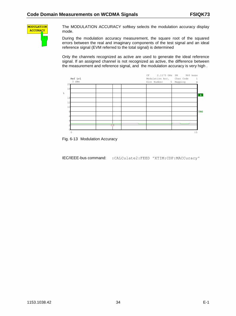
Code Domain Measurements on WCDMA Signals FSIQK73
1153.1038.42 34 E-1
MODULATIONACCURACY
The MODULATION ACCURACY softkey selects the modulation accuracy displaymode.
During the modulation accuracy measurement, the square root of the squarederrors between the real and imaginary components of the test signal and an idealreference signal (EVM referred to the total signal) is determined
Only the channels recognized as active are used to generate the ideal referencesignal. If an assigned channel is not recognized as active, the difference betweenthe measurement and reference signal, and the modulation accuracy is very high .
%
Ref Lvl3 dBmRef Lvl3 dBmRef Lvl3 dBmRef Lvl3 dBm
TRG
CF 2.1175 GHzModulation Acc.Modulation Acc.Slot Number 5Slot Number 5
SR 960 kspsChan Code 1Chan Code 1Mapping QMapping Q
B
0 15
12
14
2
4
6
8
10
12
14
18
0
20
CS
Fig. 6-13 Modulation Accuracy
IEC/IEEE-bus command: :CALCulate2:FEED "XTIM:CDP:MACCuracy"
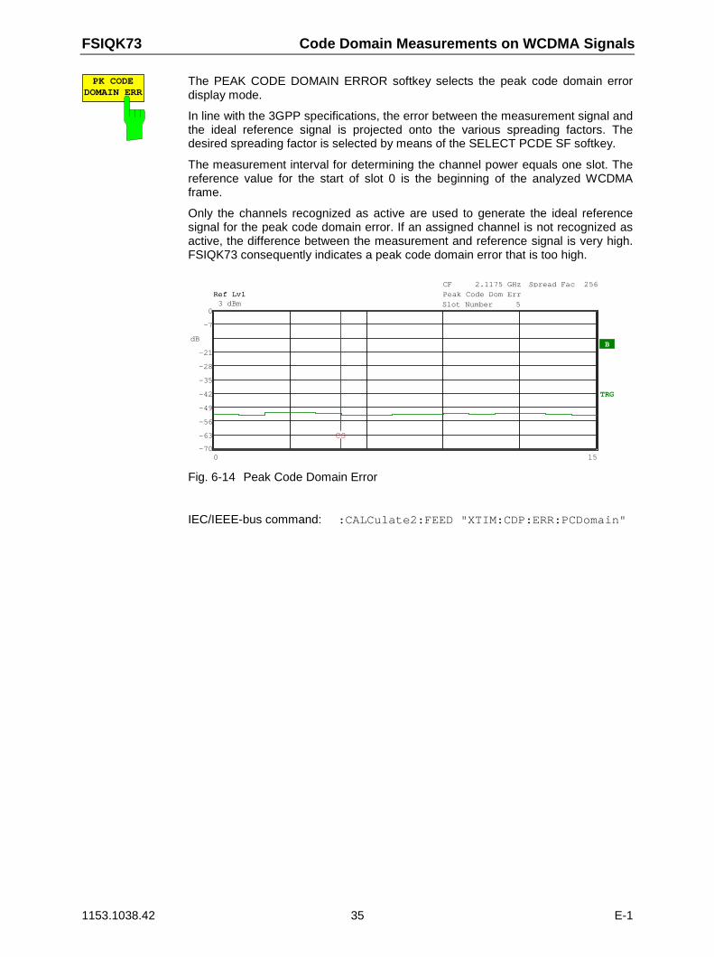
FSIQK73 Code Domain Measurements on WCDMA Signals
1153.1038.42 35 E-1
PK CODEDOMAIN ERR
The PEAK CODE DOMAIN ERROR softkey selects the peak code domain errordisplay mode.
In line with the 3GPP specifications, the error between the measurement signal andthe ideal reference signal is projected onto the various spreading factors. Thedesired spreading factor is selected by means of the SELECT PCDE SF softkey.
The measurement interval for determining the channel power equals one slot. Thereference value for the start of slot 0 is the beginning of the analyzed WCDMAframe.
Only the channels recognized as active are used to generate the ideal referencesignal for the peak code domain error. If an assigned channel is not recognized asactive, the difference between the measurement and reference signal is very high.FSIQK73 consequently indicates a peak code domain error that is too high.
dB
Ref Lvl3 dBmRef Lvl3 dBmRef Lvl3 dBmRef Lvl3 dBm
TRG
0 15
CF 2.1175 GHzPeak Code Dom ErrPeak Code Dom ErrSlot Number 5Slot Number 5
Spread Fac 256
-28
-21B
-63
-56
-49
-42
-35
-28
-21
-7
-70
0
CS
Fig. 6-14 Peak Code Domain Error
IEC/IEEE-bus command: :CALCulate2:FEED "XTIM:CDP:ERR:PCDomain"
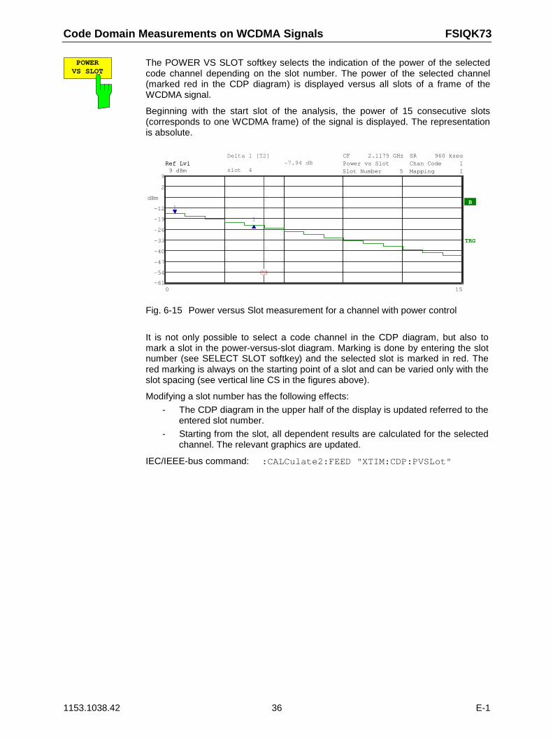
Code Domain Measurements on WCDMA Signals FSIQK73
1153.1038.42 36 E-1
POWERVS SLOT
The POWER VS SLOT softkey selects the indication of the power of the selectedcode channel depending on the slot number. The power of the selected channel(marked red in the CDP diagram) is displayed versus all slots of a frame of theWCDMA signal.
Beginning with the start slot of the analysis, the power of 15 consecutive slots(corresponds to one WCDMA frame) of the signal is displayed. The representationis absolute.
dBm
TRG
B
-19
-12
Ref Lvl9 dBmRef Lvl9 dBmRef Lvl9 dBmRef Lvl9 dBm
0 15
CF 2.1175 GHzPower vs SlotPower vs SlotSlot Number 5Slot Number 5
SR 960 kspsChan Code 1Chan Code 1Mapping IMapping I
-54
-47
-40
-33
-26
-19
-12
2
-61
9
1
1
Delta 1 [T2]-7.94 dB
slot 4
CS
Fig. 6-15 Power versus Slot measurement for a channel with power control
It is not only possible to select a code channel in the CDP diagram, but also tomark a slot in the power-versus-slot diagram. Marking is done by entering the slotnumber (see SELECT SLOT softkey) and the selected slot is marked in red. Thered marking is always on the starting point of a slot and can be varied only with theslot spacing (see vertical line CS in the figures above).
Modifying a slot number has the following effects:
- The CDP diagram in the upper half of the display is updated referred to theentered slot number.
- Starting from the slot, all dependent results are calculated for the selectedchannel. The relevant graphics are updated.
IEC/IEEE-bus command: :CALCulate2:FEED "XTIM:CDP:PVSLot"
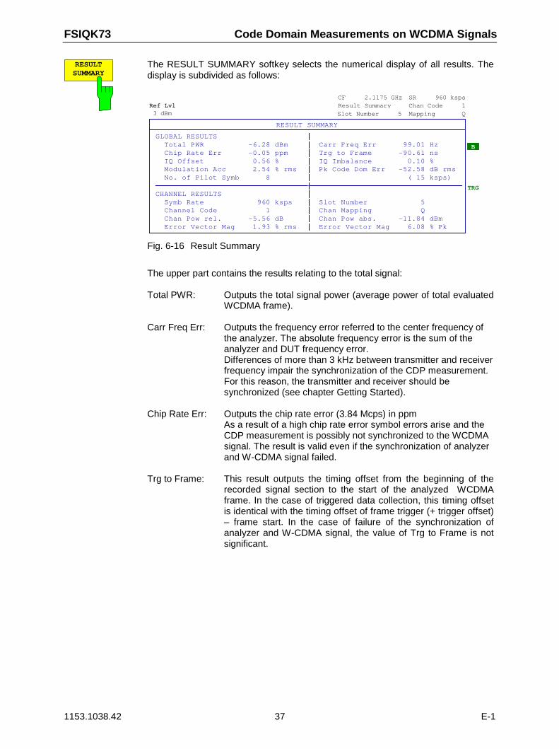
FSIQK73 Code Domain Measurements on WCDMA Signals
1153.1038.42 37 E-1
RESULTSUMMARY
The RESULT SUMMARY softkey selects the numerical display of all results. Thedisplay is subdivided as follows:
Ref Lvl3 dBm
Ref Lvl3 dBm
Ref Lvl3 dBm
Ref Lvl3 dBm
TRG
B
CF 2.1175 GHzResult SummaryResult SummarySlot Number 5Slot Number 5
SR 960 kspsChan Code 1Chan Code 1Mapping QMapping Q
RESULT SUMMARY
GLOBAL RESULTS Total PWR -6.28 dBm Carr Freq Err 99.01 HzChip Rate Err -0.05 ppm Trg to Frame -90.61 nsIQ Offset 0.56 % IQ Imbalance 0.10 %Modulation Acc 2.54 % rms Pk Code Dom Err -52.58 dB rmsNo. of Pilot Symb 8 ( 15 ksps)
©©©©©©©©©©©©©©©©©©©©©©©©©©©©©©©©©©ª©©©©©©©©©©©©©©©©©©©©©©©©©©©©©©©©©©CHANNEL RESULTS
Symb Rate 960 ksps Slot Number 5Channel Code 1 Chan Mapping QChan Pow rel. -5.56 dB Chan Pow abs. -11.84 dBmError Vector Mag 1.93 % rms Error Vector Mag 6.08 % Pk
Fig. 6-16 Result Summary
The upper part contains the results relating to the total signal:
Total PWR: Outputs the total signal power (average power of total evaluatedWCDMA frame).
Carr Freq Err: Outputs the frequency error referred to the center frequency ofthe analyzer. The absolute frequency error is the sum of theanalyzer and DUT frequency error.Differences of more than 3 kHz between transmitter and receiverfrequency impair the synchronization of the CDP measurement.For this reason, the transmitter and receiver should besynchronized (see chapter Getting Started).
Chip Rate Err: Outputs the chip rate error (3.84 Mcps) in ppmAs a result of a high chip rate error symbol errors arise and theCDP measurement is possibly not synchronized to the WCDMAsignal. The result is valid even if the synchronization of analyzerand W-CDMA signal failed.
Trg to Frame: This result outputs the timing offset from the beginning of therecorded signal section to the start of the analyzed WCDMAframe. In the case of triggered data collection, this timing offsetis identical with the timing offset of frame trigger (+ trigger offset)– frame start. In the case of failure of the synchronization ofanalyzer and W-CDMA signal, the value of Trg to Frame is notsignificant.
Code Domain Measurements on WCDMA Signals FSIQK73
1153.1038.42 38 E-1
IQ Offset: DC offset of signals in %
IQ Imbalance: IQ imbalance of signal in %
Modulation Acc: The modulation accuracy is the difference between the testsignal and the ideal reference signal (see MODULATIONACCURACY softkey). The rms average (of the analyzed frame)of the measurement results for each slot is given in the RESULTSUMMARY.
Pk Code Dom Err:The PEAK CODE DOMAIN ERROR measurement specifies aprojection of the difference between the test signal and the idealreference signal onto the selected spreading factor (see PEAKCODE DOMAIN ERR and SELECT PCDE SF softkeys). Theaverage (of the analyzed frame) of the measurement results foreach slot is indicated in the RESULT SUMMARY as an overview.The spreading factor onto which projection is made is shownbelow the measurement result.
The results of measurements on the selected channel (red in the diagram) aredisplayed in the lower part of the RESULT SUMMARY.
Symb Rate: Symbol rate at which the channel is transmitted.
Slot Number: Number of slot for which the measurement is made (see SELECT SLOT softkey)
Channel Code: Number of the spreading code of the selected channel .
Chan Mapping: Component onto which the channel is mapped (I or Q)
Chan Pow rel. / abs.:Channel relative (referred to CPICH) and absolute.
Error Vector Mag rms / Pk:Average or peak of the results of the error vector magnitudemeasurement (see SYMBOL EVM softkey).
IEC/IEEE-bus command::CALCulate2:FEED "XTIM:CDP:ERR:SUMM":CALCulate<1|2>:MARKer<1>:FUNCtion:WCDPower:MS:RESult? PTOTal | FERRor |TFRame | MACCuracy | PCDerror | EVMRms | EVMPeak | CERRor | SRATe |CHANnel | CDPabsolute | CDPRelative | IQOFfset | IQIMbalance | CMAPping | PSYMbol
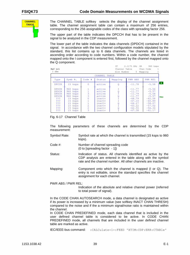
FSIQK73 Code Domain Measurements on WCDMA Signals
1153.1038.42 39 E-1
CHANNELTABLE
The CHANNEL TABLE softkey selects the display of the channel assignmenttable. The channel assignment table can contain a maximum of 256 entries,corresponding to the 256 assignable codes of the class with spreading factor 256.
The upper part of the table indicates the DPCCH that has to be present in thesignal to be analyzed in the CDP measurement.
The lower part of the table indicates the data channels (DPDCH) contained in thesignal. In accordance with the two channel configuration models stipulated by thestandard, this list contains up to 6 data channels. The channels are listed inascending order according to code numbers. Within a code number, the channelmapped onto the I component is entered first, followed by the channel mapped ontothe Q component.
Ref Lvl3 dBmRef Lvl3 dBmRef Lvl3 dBmRef Lvl3 dBm
TRG
CF 2.1175 GHzChannel TableChannel TableSlot Number 5Slot Number 5
SR 960 kspsChan Code 1Chan Code 1Mapping IMapping I
B
CHANNEL TABLE
Type Symb R. Code # Status Mapping PWR ABS PWR REL©©©©©©©ª©©©©©©©©©©ª©©©©©©©©ª©©©©©©©©©ª©©©©©©©©©©ª©©©©©©©©©©ª©©©©©©©©©DPCCH 15 ksps 0 active Q -11.78 -5.58©©©©©©©ª©©©©©©©©©©ª©©©©©©©©ª©©©©©©©©©ª©©©©©©©©©©ª©©©©©©©©©©ª©©©©©©©©©DPDCH 960 ksps 1 active I -11.77 -5.56DPDCH 960 ksps 1 active Q -11.77 -5.57DPDCH 960 ksps 3 active I -11.79 -5.58DPDCH 960 ksps 3 active Q -11.77 -5.57??? 15 ksps 0 inactv I -68.79 -62.58??? 15 ksps 1 inactv I -67.10 -60.89??? 15 ksps 1 inactv Q -64.27 -58.07??? 15 ksps 2 inactv I -63.22 -57.02??? 15 ksps 2 inactv Q -62.55 -56.34??? 15 ksps 3 inactv I -67.38 -61.17
Fig. 6-17 Channel Table
The following parameters of these channels are determined by the CDPmeasurement:
Symbol Rate: Symbol rate at which the channel is transmitted (15 ksps to 960ksps).
Code #: Number of channel spreading code(0 to [spreading factor - 1])
Status: Indication of status. All channels identified as active by theCDP analysis are entered in the table along with the symbolrate and the channel number. All other channels are inactive.
Mapping: Component onto which the channel is mapped (I or Q). Theentry is not editable, since the standard specifies the channelassignment for each channel.
PWR ABS / PWR REL:Indication of the absolute and relative channel power (referredto total power of signal).
In the CODE CHAN AUTOSEARCH mode, a data channel is designated as activeif its power is increased by a minimum value (see softkey INACT CHAN THRESH)compared to the noise and if the a minimum signal/noise ratio is maintained withinthe channel.In CODE CHAN PREDEFINED mode, each data channel that is included in theuser defined channel table is considered to be active. In CODE CHANPREDEFINED mode, all channels that are included in the user defined channeltable are marked as active.
IEC/IEEE-bus command: :CALCulate<1>:FEED "XTIM:CDP:ERR:CTABle"
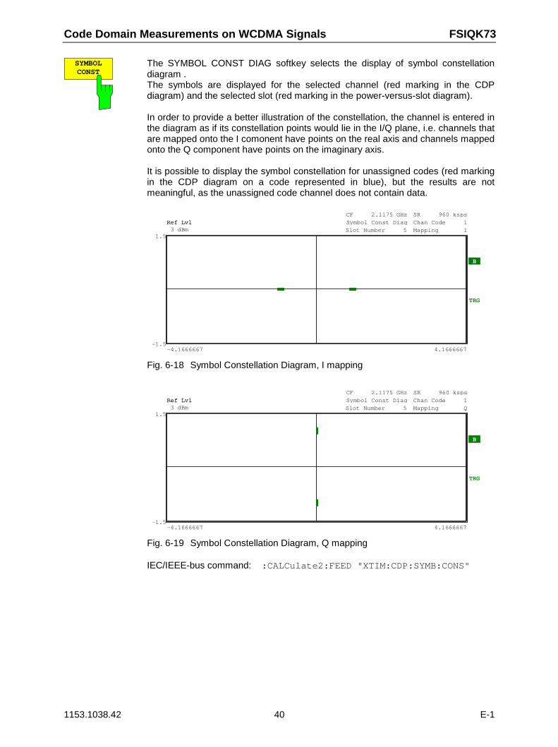
Code Domain Measurements on WCDMA Signals FSIQK73
1153.1038.42 40 E-1
SYMBOLCONST
The SYMBOL CONST DIAG softkey selects the display of symbol constellationdiagram .The symbols are displayed for the selected channel (red marking in the CDPdiagram) and the selected slot (red marking in the power-versus-slot diagram).
In order to provide a better illustration of the constellation, the channel is entered inthe diagram as if its constellation points would lie in the I/Q plane, i.e. channels thatare mapped onto the I comonent have points on the real axis and channels mappedonto the Q component have points on the imaginary axis.
It is possible to display the symbol constellation for unassigned codes (red markingin the CDP diagram on a code represented in blue), but the results are notmeaningful, as the unassigned code channel does not contain data.
Ref Lvl3 dBmRef Lvl3 dBmRef Lvl3 dBmRef Lvl3 dBm
TRG
-4.1666667 4.1666667
CF 2.1175 GHzSymbol Const DiagSymbol Const DiagSlot Number 5Slot Number 5
SR 960 kspsChan Code 1Chan Code 1Mapping IMapping I
B
-1.5
1.5
Fig. 6-18 Symbol Constellation Diagram, I mapping
Ref Lvl3 dBmRef Lvl3 dBmRef Lvl3 dBmRef Lvl3 dBm
TRG
B
-4.1666667 4.1666667
CF 2.1175 GHzSymbol Const DiagSymbol Const DiagSlot Number 5Slot Number 5
SR 960 kspsChan Code 1Chan Code 1Mapping QMapping Q
-1.5
1.5
Fig. 6-19 Symbol Constellation Diagram, Q mapping
IEC/IEEE-bus command: :CALCulate2:FEED "XTIM:CDP:SYMB:CONS"
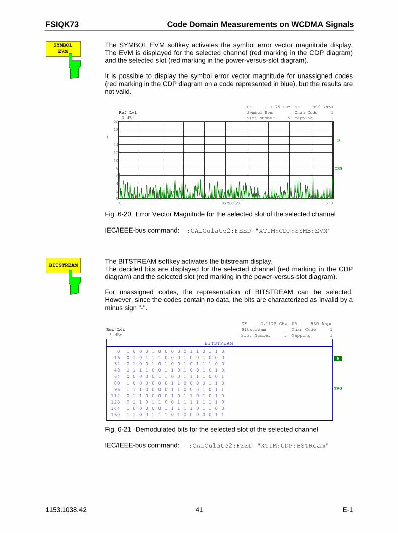
FSIQK73 Code Domain Measurements on WCDMA Signals
1153.1038.42 41 E-1
SYMBOLEVM
The SYMBOL EVM softkey activates the symbol error vector magnitude display.The EVM is displayed for the selected channel (red marking in the CDP diagram)and the selected slot (red marking in the power-versus-slot diagram).
It is possible to display the symbol error vector magnitude for unassigned codes(red marking in the CDP diagram on a code represented in blue), but the results arenot valid.
%
Ref Lvl3 dBmRef Lvl3 dBmRef Lvl3 dBmRef Lvl3 dBm
TRG
12
14B
0 639SYMBOLS
CF 2.1175 GHzSymbol EvmSymbol EvmSlot Number 5Slot Number 5
SR 960 kspsChan Code 1Chan Code 1Mapping IMapping I
2
4
6
8
10
12
14
18
0
20
Fig. 6-20 Error Vector Magnitude for the selected slot of the selected channel
IEC/IEEE-bus command: :CALCulate2:FEED "XTIM:CDP:SYMB:EVM"
BITSTREAMThe BITSTREAM softkey activates the bitstream display.The decided bits are displayed for the selected channel (red marking in the CDPdiagram) and the selected slot (red marking in the power-versus-slot diagram).
For unassigned codes, the representation of BITSTREAM can be selected.However, since the codes contain no data, the bits are characterized as invalid by aminus sign "-".
Ref Lvl3 dBmRef Lvl3 dBmRef Lvl3 dBmRef Lvl3 dBm
TRG
CF 2.1175 GHzBitstreamBitstreamSlot Number 5Slot Number 5
SR 960 kspsChan Code 1Chan Code 1Mapping IMapping I
B
BITSTREAM
0 1 0 0 0 1 0 0 0 0 0 1 1 0 1 1 016 0 1 0 1 1 1 0 0 0 1 0 0 1 0 0 032 0 1 0 0 1 0 1 0 0 1 0 1 1 1 0 048 0 1 1 1 0 0 1 1 0 1 0 0 1 0 1 064 0 0 0 0 0 1 1 0 0 1 1 1 1 0 0 180 1 0 0 0 0 0 0 1 1 0 0 0 0 1 1 096 1 1 1 0 0 0 0 1 1 0 0 0 1 0 1 1
112 0 1 1 0 0 0 0 1 0 1 1 0 1 0 1 0128 0 1 1 0 1 1 0 0 1 1 1 1 1 1 1 0144 1 0 0 0 0 0 1 1 1 1 1 0 1 1 0 0160 1 1 0 0 1 1 1 0 1 0 0 0 0 0 1 1
Fig. 6-21 Demodulated bits for the selected slot of the selected channel
IEC/IEEE-bus command: :CALCulate2:FEED "XTIM:CDP:BSTReam"
Code Domain Measurements on WCDMA Signals FSIQK73
1153.1038.42 42 E-1
SELECTPCDE SF
The SELECT PCDE SF softkey activates the entry of the class of codes onto whichthe error vector is to be projected for the PEAK CODE DOMAIN ERROR display.The entry of the spreading factor is only possible for this display mode, it has noeffect on any other display mode.
IEC/IEEE-bus command::[SENSe:]CDPower:SFACtor 4|8|16|32|64|128|256
SELECTI Q
The SELECT I/Q softkey switches the display modes CDP PWR RELATIVE/ABSOLUTE, CODE PWR ZOOM, POWER VS SLOT, SYMBOL CONST, SYMBOLEVM between indication of I and Q component. Only channels that are mappedonto the corresponding component are taken into account by the respective displaymodes.
IEC/IEEE-bus command: :[SENSe:]CDPower:MAPPing Q
SELECTCODE NO.
The SELECT CODE NO softkey activates the selection of a channel for the displaymodes CDP PWR RELATIVE/ABSOLUTE, CODE PWR ZOOM, POWER VSSLOT, SYMBOL CONST, SYMBOL EVM.
The entry is made on the basis of the code class with spreading factor 256. Thenumber of the spreading code which the required channel has at its actualtransmission rate has to be converted into spreading factor 256. The entered codecorrelates with the channel marked in red in the CDP diagram.
If the entered code corresponds to an active channel, the whole associated channelis marked. If it corresponds to a gap between the channels, only the entered codeis marked.If the code number is modified using the rollkey, the red marking changes itsposition in the diagram only if the code number no longer belongs to the markedchannel.
IEC/IEEE-bus command: :[SENSe:]CDPower:CODE 0 to 255
SELECTCPICH SLOT
The SELECT SLOT softkey activates the selection of the slot number for thedisplay modes POWER VS SLOT, SYMBOL CONST, SYMBOL EVM.
When the slot number is entered, the red marking in the power-versus-slot diagramchanges its position in steps of 2560 chips.
IEC/IEEE-bus command: :[SENSe:]CDPower:SLOT 0 to 14
FSIQK73 Code Domain Measurements on WCDMA Signals
1153.1038.42 43 E-1
Measurement Configuration
CONFIGURATION - MODE - 3GPP MS ANALYZER - CODE CHAN CONFIG sub menu
CODE CHAN
CODE CHANCONFIG
CODE CHAN
AUTOSEARCH
PREDEFINED
PAGE UP
PAGE DOWN
EDIT CHANCONF TABLE
DEL CHANCONF TABLE
COPY CHANCONF TABLE
CODE CHANCONFIG
The CODE CHAN CONFIG softkey opens a submenu with differentconfigurations for measurements. In this submenu, predefined channeltables can be selected and edited as a basis for code domainmeasurements. When the softkey is selected, a table including the channel tables storedon the measuring instrument’s hard disk is opened. The table providesjust an overview and a table for the measurement can only be selectedafter actuating the CODE CHAN PREDEFINED softkey.
IEC-Bus-Befehl::CONFigure:WCDPower:MS:CTABle:CATalog?
CODE CHANAUTOSEARCH
The CODE CHAN AUTOSEARCH softkey allows code domain powermeasurements in the automatic search mode. In this mode, the wholecode domain (all permissible symbol rates and channel numbers) issearched for active channels. Detecting an active channel is performedby a comparison of the channel power with the total power of the signal. The CODE CHAN AUTOSEARCH mode is the preset search modestarting the CDP analysis. It is mainly intended for giving the user anoverview of the channels contained in the signal. If the signal containschannels that are not detected as being active in the automatic searchmode, the CDP analysis can be performed with the channelconfigurations predefined by the user by switching to the CODE CHANPREDEFINED mode.
IEC/IEEE-bus command:CONFigure:WCDPower:MS:CTABle[:STATe] OFF
CODE CHANPREDEFINED
The CODE CHAN PREDEFINED softkey activates the predefinedchannel table mode. No search for active channels in the code domainis performed in this mode, but the channels contained in a channel tabledefined prior to the measurement are assumed to be active. The codedomain power measurement and all further evaluations are carried outfor these channels.
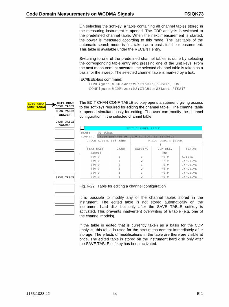
Code Domain Measurements on WCDMA Signals FSIQK73
1153.1038.42 44 E-1
On selecting the softkey, a table containing all channel tables stored inthe measuring instrument is opened. The CDP analysis is switched tothe predefined channel table. When the next measurement is started,the power is measured according to this mode. The last table of theautomatic search mode is first taken as a basis for the measurement.This table is available under the RECENT entry. Switching to one of the predefined channel tables is done by selectingthe corresponding table entry and pressing one of the unit keys. Fromthe next measurement onwards, the selected channel table is taken as abasis for the sweep. The selected channel table is marked by a tick.
IEC/IEEE-bus command:CONFigure:WCDPower:MS:CTABle[:STATe] ONCONFigure:WCDPower:MS:CTABle:SELect "TEST"
EDIT CHANCONF TABLE
CHAN TABLE
EDIT CHANCONF TABLE
VALUES
HEADER
CHAN TABLE
SAVE TABLE
The EDIT CHAN CONF TABLE softkey opens a submenu giving accessto the softkeys required for editing the channel table. The channel tableis opened simultaneously for editing. The user can modify the channelconfiguration in the selected channel table
EDIT CHANNEL TABLE
NAME: UL_1Chan
COMMENT: Table scanned on July 02 2001 at 14:30:02
DPCCH ACTIVE @15 ksps PILOT LENGTH [bits]
8
SYMB RATE CHAN# MAPPING CDP REL. STATUS
[ksps] [dB]
960.0 1 I -6.9 ACTIVE
960.0 1 Q -7.0 INACTIVE
960.0 2 I -6.9 INACTIVE
960.0 2 Q -6.9 INACTIVE
960.0 3 I -6.9 INACTIVE
960.0 3 Q -6.9 INACTIVE
Fig. 6-22 Table for editing a channel configuration
It is possible to modify any of the channel tables stored in theinstrument. The edited table is not stored automatically on theinstrument hard disk but only after the SAVE TABLE softkey isactivated. This prevents inadvertent overwriting of a table (e.g. one ofthe channel models). If the table is edited that is currently taken as a basis for the CDPanalysis, this table is used for the next measurement immediately afterstorage. The effects of modifications in the table are therefore visible atonce. The edited table is stored on the instrument hard disk only afterthe SAVE TABLE softkey has been activated.
FSIQK73 Code Domain Measurements on WCDMA Signals
1153.1038.42 45 E-1
If the a table is edited that is stored on the instrument hard disk butcurrently not activated, the modifications are visible after storage (SAVETABLE softkey) and subsequent activation. The table structure for editing the channel configuration is based on the3GPP specifications: The FSIQK73 software distinguishes between the one data channel andmulti-data channel configurations. The activation of a second datachannel switches from the single-channel model to the multichannelmodel and vice versa. For the one data channel configuration, the entrySYMBOL RATE can be edited in the table. This editing function is notpossible for several data channels. For several data channels, thenumbering sequence of channel codes is prescribed. Therefore, theconfiguration is automatically adapted by the software whenactivating/deactivating the channels.
CHAN TABLEHEADER
The CHAN TABLE HEADER softkey enables the user to edit the tableheader. The table name can be changed to prevent overwriting storedtables. The name of a table may not contain more than 8 characters. The table header also includes editable entry PILOT LENGTH, which isgloabally processed for the total signal in the FSIQK73.
IEC/IEEE command::CONFigure:WCDPower:MS:CTABle:NAME "NEW_TAB"
CHAN TABLEVALUES
The CHAN TABLE VALUES softkey enables the user to edit the entries inthe channel table. The following entries are available for each channelcontained in the table (entry is confirmed using the unit hardkeys): SYMBOL RATE: Symbol rate at which the channel is transmitted. This
entry can only be edited for channel configuration 1with 1 data channel.
CHAN NO: Number of the channel in the associated transmission
class. This entry can neither be edited for channelsconfiguration 1 nore for channel configuration 2, as thechannel numbers are defined in the standard for singlechannel and multi channel mode. In the case of singlechannel, the entry is adapted to the selected symbolrate
MAPPING: Component onto which the channel is mapped (I or Q).
The entry is not editable, since the standard specifiesthe channel assignment for each channel.
CDP REL.: Information about the relative channel power. This
entry cannot be edited and is only available for theRECENT table, it is used for detecting low-powerchannels.
Code Domain Measurements on WCDMA Signals FSIQK73
1153.1038.42 46 E-1
STATUS: channel status (active/inactive). Modifying the channelstatus blanks out a channel entered in the table from theCDP analysis without the user having to clear theassociated entry from the table. Only channels with anactive channel status are used for the CDP analysis.Activating/deactivating channels switches between thesingle-channel model and the mutliple-channel model. Incase of several channels, activating/deactivatingchannels automatically adapts the channel configurationaccording to the 3GPP specifications.
IEC/IEEE commands::CONFigure:WCDPower:MS:CTABle:DATA 8,4,1
:CONFigure:WCDPower:MS:CTABle:COMMent "Comment fornew table"
SAVETABLE
The SAVE TABLE softkey saves the table under the specified name.
IEC/IEEE command: -- (automatically executed in remote control)
DEL CHANCONF TABLE
The DEL CHAN CONF TABLE softkey deletes the selected table. InCODE CHAN PREDEFINED mode, the currently active table can not bedeleted.
IEC/IEEE command::CONFigure:WCDPower:MS:CTABle:SELect "CTAB2":CONFigure:WCDPower:MS:CTABle:DELete
COPY CHANCONF TABLE
The COPY CHAN CONF TABLE softkey copies the selected table. Thename for the copy is requested. IEC/IEEE command:
:CONFigure:WCDPower:MS:CTABle:SELect "CTAB2":CONFigure:WCDPower:MS:CTABle:COPY "NEW_CTAB"
PAGE UP The PAGE UP softkey is used to scroll through the selection table.
PAGE DOWN
The PAGE DOWN softkey is used to scroll through the selection table. .
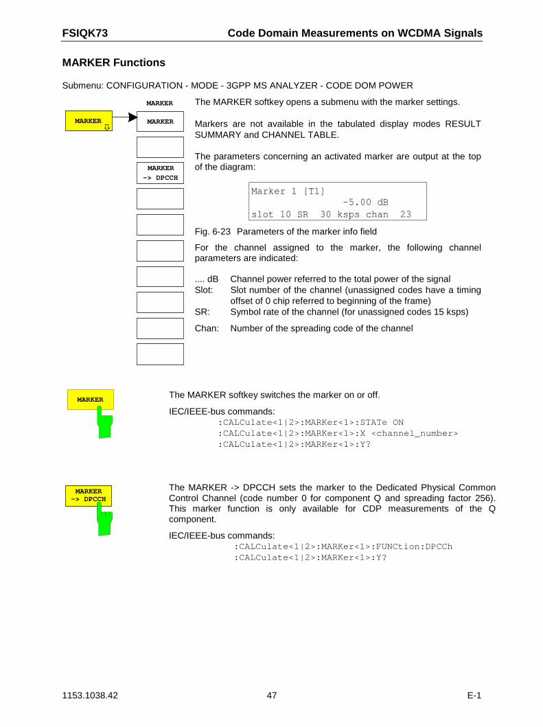
FSIQK73 Code Domain Measurements on WCDMA Signals
1153.1038.42 47 E-1
MARKER Functions
Submenu: CONFIGURATION - MODE - 3GPP MS ANALYZER - CODE DOM POWER
MARKER
MARKER
-> DPCCH
MARKER
MARKER
The MARKER softkey opens a submenu with the marker settings. Markers are not available in the tabulated display modes RESULTSUMMARY and CHANNEL TABLE.
The parameters concerning an activated marker are output at the topof the diagram:
Marker 1 [T1]-5.00 dB
slot 10 SR 30 ksps chan 23
Fig. 6-23 Parameters of the marker info field
For the channel assigned to the marker, the following channelparameters are indicated:
.... dB Channel power referred to the total power of the signalSlot: Slot number of the channel (unassigned codes have a timing
offset of 0 chip referred to beginning of the frame)SR: Symbol rate of the channel (for unassigned codes 15 ksps)
Chan: Number of the spreading code of the channel
MARKERThe MARKER softkey switches the marker on or off.
IEC/IEEE-bus commands::CALCulate<1|2>:MARKer<1>:STATe ON:CALCulate<1|2>:MARKer<1>:X <channel_number>:CALCulate<1|2>:MARKer<1>:Y?
-> DPCCHMARKER The MARKER -> DPCCH sets the marker to the Dedicated Physical Common
Control Channel (code number 0 for component Q and spreading factor 256).This marker function is only available for CDP measurements of the Qcomponent.
IEC/IEEE-bus commands::CALCulate<1|2>:MARKer<1>:FUNCtion:DPCCh:CALCulate<1|2>:MARKer<1>:Y?
Code Domain Measurements on WCDMA Signals FSIQK73
1153.1038.42 48 E-1
Configuration of CDP Measurement – MEAS SETTINGS
Submenu: CONFIGURATION - MODE - 3GPP MS ANALYZER - CODE DOM POWER
MEASSETTINGS
SCRAMBLINGCODE
CENTERFREQUENCY
MEAS
SIDE BANDNORM INV
SETTINGS
NORMALIZE
OFFON
EXT TRIGOFFSET
TRIGGERINT EXT
INACT CHANTHRESHOLD
LONG SHRTSCR TYPE
The MEAS SETTINGS softkey opens a submenu with settingparameters for the CDP measurement.
CODESCRAMBLING The SCRAMBLING CODE softkey opens a window for entering the scrambling
code. The scrambling code is input in hex format.
The entered scrambling code has to coincide with that of the signal. Otherwisea CDP measurement of the signal is not possible.
IEC/IEEE-bus command: :[SENSe:]CDPower:LCODe[:VALue] #H2
LONG SHRTSCR TYPE The SCR TYPE LONG/SHRT softkey determines whether the scrambling code
entered (see softkey SCRAMBLING CODE) is to be handled as long or shortscrambling code.
IEC/IEEE-bus command: :[SENSe:]CDPower:LCODe:TYPE SHORt
FSIQK73 Code Domain Measurements on WCDMA Signals
1153.1038.42 49 E-1
INACT CHANTHRESH
The INACT CHAN THRESH softkey activates the entry of the minimum powerwhich a single channel should have as compared to the total signal in order tobe considered an active channel.
Channels which are below the specified threshold are considered to be notactive. Channels that are not active appear in blue colour in the CDP diagram.
The two measurements MODULATION ACCURACY and PEAK CODEDOMAIN ERROR, specified as measurements on the total signal, areperformed with the aid of the list of active channels. These two measurementsare falsified whenever active channels are recognized as not active (see aboveexample) or if unassigned codes get the status "assigned channel". INACTCHAN THRESHOLD is therefore used to influence the results of the twomeasurements.
The default value is -10 dB. If not all channels in the signal are automaticallydetected with this setting, INACT CHAN THRES has to be incremented.
IEC/IEEE-bus command: :[SENSe:]CDPower:ICTReshold -50dB to +10dB
INT EXTTRIGGER The TRIGGER INT EXT softkey switches between internal (FREE RUN) and
external triggering.
For internal triggering, at the beginning of the measurement a section (approx.20 ms) of the signal, which must contain at least one frame of the WCDMAsignal, is recorded and analyzed at a moment which cannot be determined bythe user. The start of the next complete WCDMA frame is searched for in therecorded signal section and the signal is measured from this point.
In case of external triggering, FSIQK73 expects a trigger at the beginning of theWCDMA frame (frame trigger). There is no search for the beginning of theframe in the recorded signal section. The start of the WCDMA frame is onlysearched for within the first 2560 chips after the trigger event.For external triggering the trigger output of the mobile station has to beconnected to the FSIQ trigger input at the rear panel of the instrument.
Since with internal triggering the start of the next complete WCDMA frame islocated in the middle of the recorded signal section (after approx. 10 ms) in theworst case, an external frame trigger reduces the search time for the frame startand consequently the computing time for the overall measurement.
IEC/IEEE-bus command: :TRIGger[:SEQuence]:SOURce IMMediate|EXTernal
Code Domain Measurements on WCDMA Signals FSIQK73
1153.1038.42 50 E-1
EXT TRGOFFSET
The EXT TRG OFFSET softkey activates the entry of the offset for externaltriggering (step width 40 ns).The trigger offset can compensate for the shift of the frame trigger at the actualstart of a frame. In the RESULT DISPLAY mode, the interval between the triggerevent and the start of the WCDMA frame is indicated under "Trg to Frame". Anoffset of the trigger event influences the interval specified there.
If the trigger offset is set inadequately, the measurement may not be able todetect the start of a WCDMA frame in the search range. In this case, themeasurement results are invalid and the code power of each channel isdisplayed in blue with almost the same level.
A modification of the trigger offset can influence the search range of FSIQK73and thus secure the feasibility of the measurement.
IEC/IEEE-bus command: :TRIGger:SEQuence:HOLDoff <num_value>
SIDE BANDNORM INV
The SIDE BAND NORM / INV softkey is used to perform the measurement bothin the normal (NORM) and inverted position (INV).
NORM The normal position allows the measurement of RF signals from themobile station.
INV The inverted position is useful for measurements on IF modules orcomponents in case of spectral inversion.
The default setting is INV.
IEC/IEEE-bus command: :[SENSe:]CDPower:SBANd NORMal|INVers
NORMALIZEON OFF
The NORMALIZE ON / OFF softkey eliminates the DC offset of the signal.Default setting is OFF.
IEC/IEEE-bus command : [SENSe:]CDPower:NORMalize OFF
FREQUENCYCENTER The CENTER FREQUENCY activates the input of the center frequency of the
WCDMA signal.
IEC/IEEE-bus command: :[SENSe:]FREQuency:CENTer 870.03 MHz
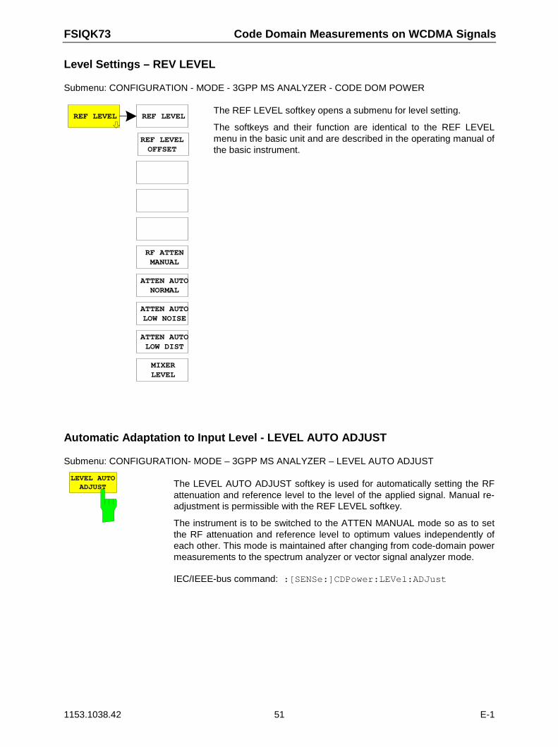
FSIQK73 Code Domain Measurements on WCDMA Signals
1153.1038.42 51 E-1
Level Settings – REV LEVEL
Submenu: CONFIGURATION - MODE - 3GPP MS ANALYZER - CODE DOM POWER
REF LEVEL REF LEVEL
REF LEVELOFFSET
RF ATTENMANUAL
ATTEN AUTONORMAL
ATTEN AUTOLOW NOISE
ATTEN AUTOLOW DIST
MIXERLEVEL
The REF LEVEL softkey opens a submenu for level setting.
The softkeys and their function are identical to the REF LEVELmenu in the basic unit and are described in the operating manual ofthe basic instrument.
Automatic Adaptation to Input Level - LEVEL AUTO ADJUST
Submenu: CONFIGURATION- MODE – 3GPP MS ANALYZER – LEVEL AUTO ADJUST
LEVEL AUTOADJUST The LEVEL AUTO ADJUST softkey is used for automatically setting the RF
attenuation and reference level to the level of the applied signal. Manual re-adjustment is permissible with the REF LEVEL softkey.
The instrument is to be switched to the ATTEN MANUAL mode so as to setthe RF attenuation and reference level to optimum values independently ofeach other. This mode is maintained after changing from code-domain powermeasurements to the spectrum analyzer or vector signal analyzer mode.
IEC/IEEE-bus command: :[SENSe:]CDPower:LEVel:ADJust
Code Domain Measurements on WCDMA Signals FSIQK73
1153.1038.42 52 E-1
Automatic Setting of CDP Measurement Mode - CDP AUTO ADJUST
Submenu: CONFIGURATION - MODE - 3GPP MS ANALYZER - CODE DOM POWER
ADJUSTCDP AUTO The CDP AUTO ADJUST softkey automatically adapts the settings of the
CDP measurement in such a way that a valid measurement on the signal ispossible with high probability. For this purpose
- the following measurement parameters are set to predefined values:Trigger: FREE RUNMarker / delta marker: OFFCode number: 0Slot number: 0Symbol rate: 15 ksps (referred to DPCCH)
- RF attenuation and reference level are set using LEVEL AUTOADJUST
- a SINGLE SWEEP is carried out.
With these settings, the CDP measurement can be performed with highprobability, provided a valid WCDMA signal to 3GPP is applied to the RFinput of analyzer. The parameters CENTER FREQUENCY, SCRAMBLINGCODE, SCR TYPE LONG/SHORT as well as an external reference for themeasurement have to be manually adapted to the signal.
IEC/IEEE-bus command: :[SENSe:]CDPower:PRESet
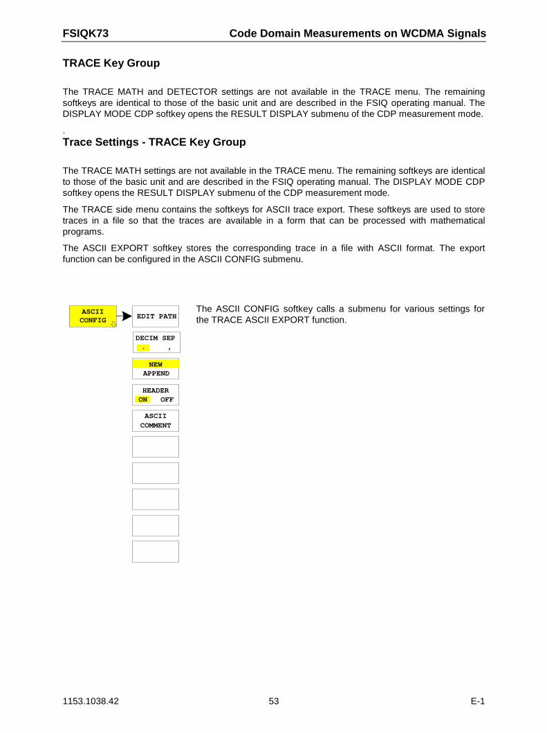
FSIQK73 Code Domain Measurements on WCDMA Signals
1153.1038.42 53 E-1
TRACE Key Group
The TRACE MATH and DETECTOR settings are not available in the TRACE menu. The remainingsoftkeys are identical to those of the basic unit and are described in the FSIQ operating manual. TheDISPLAY MODE CDP softkey opens the RESULT DISPLAY submenu of the CDP measurement mode.
.Trace Settings - TRACE Key Group
The TRACE MATH settings are not available in the TRACE menu. The remaining softkeys are identicalto those of the basic unit and are described in the FSIQ operating manual. The DISPLAY MODE CDPsoftkey opens the RESULT DISPLAY submenu of the CDP measurement mode.
The TRACE side menu contains the softkeys for ASCII trace export. These softkeys are used to storetraces in a file so that the traces are available in a form that can be processed with mathematicalprograms.
The ASCII EXPORT softkey stores the corresponding trace in a file with ASCII format. The exportfunction can be configured in the ASCII CONFIG submenu.
ASCIIEDIT PATH
DECIM SEP. ,
APPEND
HEADERON OFF
ASCIICOMMENT
CONFIG
NEW
The ASCII CONFIG softkey calls a submenu for various settings forthe TRACE ASCII EXPORT function.
Code Domain Measurements on WCDMA Signals FSIQK73
1153.1038.42 54 E-1
EDIT PATHThe EDIT PATH softkey defines the directory in which the file is to bestored.
IEC/IEEE-bus command --
DECIM SEP. ,
The DECIM SEP softkey selects the decimal separator for the ASCIIfile. The choice is ’.’ (decimal point) or ’,’ (comma).This means that the decimal separator used in various languageversions of evaluation programs (e.g. MS-Excel) can be selected sothat the packages are supported. .
IEC/IEEE-bus command:FORMat:DEXPort:DSEParator POINt|COMMa
NEWAPPEND
The APPEND NEW softkey defines whether output data are to bewritten to an existing file or a new file.
• With APPEND, the data are added to an existing file.
• With NEW, either a new file is generated or an existing file isoverwritten by storage of the data.
IEC/IEEE-bus command :FORMat:DEXPort:APPend ON | OFF
HEADERON OFF
The HEADER ON/OFF softkey defines whether important instrumentsettings should be stored at the beginning of the file. The generaldevice settings entered in the file header allow test results to bereproduced. A file header may impair data processing by mathematicalprograms.
IEC/IEEE-bus command :FORMat:DEXPort:HEADer ON|OFF
ASCIICOMMENT
The ASCII COMMENT softkey activates the entry of commentaryconcerning the current ASCII data set. A total of 60 characters areavailable for this purpose.
IEC\IEEE bus command :FORMat:DEXPort:COMMent ’string’
ASCIIEXPORT
In CDP measurement mode, the ASCII EXPORT softkey stores thecorresponding trace in a file with ASCII format.
Upon pressing the ASCII EXPORT softkey, a file name can beentered. The default name is TRACE.DAT. Then the measured data ofthe trace are stored.
IEC-Bus-Befehl :MMEMory:STORe:TRACe 1..4,<Pfad mitFilenamen>
FSIQK73 Code Domain Measurements on WCDMA Signals
1153.1038.42 55 E-1
Structure of the ASCII file for CDPower measurements and measurements of signal spectrum:
The file consists of the header containing important scaling parameters and a data section containingthe trace data. The data of the file header consist of three columns, each separated by a semicolon:parameter name; numeric value; basic unit
The data section starts with the keyword " Trace <n> " (<n> = number of stored trace), followed by themeasured data in one or several columns (depending on measurement) which are also separated by asemicolon.This format can be read in from spreadsheet calculation programs, eg MS-Excel. It is necessary todefine ’;’ as a separator.
1) Format for CDP measurements
Content of file Description
File header Type;FSIQ 7;
Version;4.107;
Date;26.Mar 2001;
Comment;ASCII-Darstellung;
Mode;CDP;
Measurement;Code Domain Power;
Digital Standard;WCDMA 3GPP REV;
Center Freq;2117500000.000000;Hz;
Freq Offset;0.000000;Hz;
Ref. Level;-6.000000;dBm;
Level Offset;0.000000;dB;
RF Att;10.000000;dB;
y per div;2;dB;
Ref Value y-Axis;0;dB;
Ref Value Position;100.000000;%;
Sweep Count;0;
Spreading Factor;256;
Reference Slot;0;
Channel Slot;0;
First Slot;0;
Code Number;0;
Scrambling Code;0000H;
Scr Type;Long;
Channel Threshold;10;
Invert Sideband;OFF;
Normalize;OFF;
Invert Q;OFF;
Instrument model
Firmware version
Date record storage date
Comment
Instrument operating mode
Display mode (CDP, bitstream, ...)
Digital standard (3GPP REV, 3GPP FWD)
Center frequency
Frequency offset
Reference level
Level offset
Input attenuation
Scaling of y axis per division
Scaling of y axis, reference value
Scaling of y axis, position of reference value
Number of sweeps set
Spreading factor
Slot of the reference channel (identical to channel slot)
Channel slot
First slot
Code number: 0 to 255
Scrambling code: 0000 to 1FFFH
Scrambling type: : Long, Short, N/A
Channel threshold
Sideband normal, inverted; ON, OFF;
Normalize;ON, OFF;
Invert Q;ON, OFF; N/A
Data section of thefile (CDP abs / CDPrel / Channel Table)
TRACE 1:
Trace Mode;CLR/WRITE;
Values;238;
4;0;-13.643795;-3.643795;0;8;1;
8;32;-41.409958;-31.409958;0;8;0;
8;33;-43.137810;-33.137810;0;8;0;
8;34;-35.651539;-25.651539;0;8;1;
8;35;-41.930389;-31.930389;0;8;1;
8;36;-38.120872;-28.120872;0;8;1;
...
Trace
Display mode of trace:(CLR/WRITE,AVERAGE,MAXHOLD,MINHOLD)
Number of data blocks / measurement values
<CodeClass>;<CodeNumber>;<yabs>;<yrel>;
<TimingOffset>;<PilotLength>;<Mapping>;
Values <TimingOffset> and <PilotLength> are not relevantfor FSIQK73.
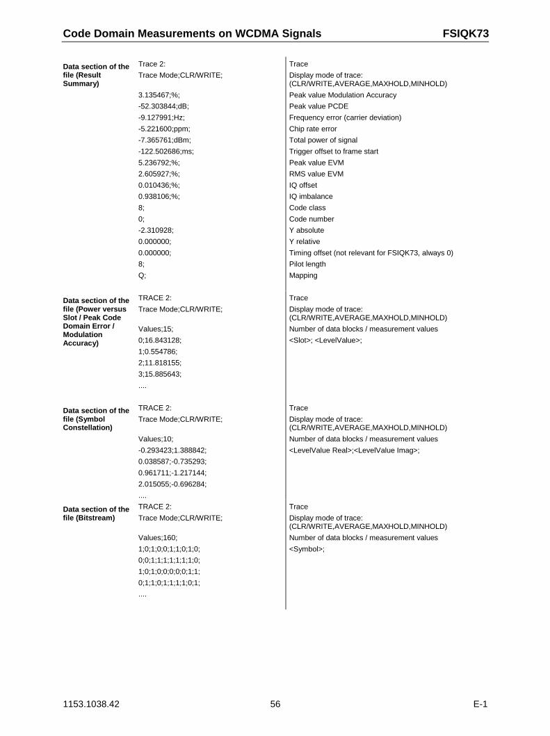
Code Domain Measurements on WCDMA Signals FSIQK73
1153.1038.42 56 E-1
Data section of thefile (ResultSummary)
Trace 2:
Trace Mode;CLR/WRITE;
3.135467;%;
-52.303844;dB;
-9.127991;Hz;
-5.221600;ppm;
-7.365761;dBm;
-122.502686;ms;
5.236792;%;
2.605927;%;
0.010436;%;
0.938106;%;
8;
0;
-2.310928;
0.000000;
0.000000;
8;
Q;
Trace
Display mode of trace:(CLR/WRITE,AVERAGE,MAXHOLD,MINHOLD)
Peak value Modulation Accuracy
Peak value PCDE
Frequency error (carrier deviation)
Chip rate error
Total power of signal
Trigger offset to frame start
Peak value EVM
RMS value EVM
IQ offset
IQ imbalance
Code class
Code number
Y absolute
Y relative
Timing offset (not relevant for FSIQK73, always 0)
Pilot length
Mapping
Data section of thefile (Power versusSlot / Peak CodeDomain Error /ModulationAccuracy)
TRACE 2:
Trace Mode;CLR/WRITE;
Values;15;
0;16.843128;
1;0.554786;
2;11.818155;
3;15.885643;
....
Trace
Display mode of trace:(CLR/WRITE,AVERAGE,MAXHOLD,MINHOLD)
Number of data blocks / measurement values
<Slot>; <LevelValue>;
Data section of thefile (SymbolConstellation)
TRACE 2:
Trace Mode;CLR/WRITE;
Values;10;
-0.293423;1.388842;
0.038587;-0.735293;
0.961711;-1.217144;
2.015055;-0.696284;
....
Trace
Display mode of trace:(CLR/WRITE,AVERAGE,MAXHOLD,MINHOLD)
Number of data blocks / measurement values
<LevelValue Real>;<LevelValue Imag>;
Data section of thefile (Bitstream)
TRACE 2:
Trace Mode;CLR/WRITE;
Values;160;
1;0;1;0;0;1;1;0;1;0;
0;0;1;1;1;1;1;1;1;0;
1;0;1;0;0;0;0;0;1;1;
0;1;1;0;1;1;1;1;0;1;
....
Trace
Display mode of trace:(CLR/WRITE,AVERAGE,MAXHOLD,MINHOLD)
Number of data blocks / measurement values
<Symbol>;
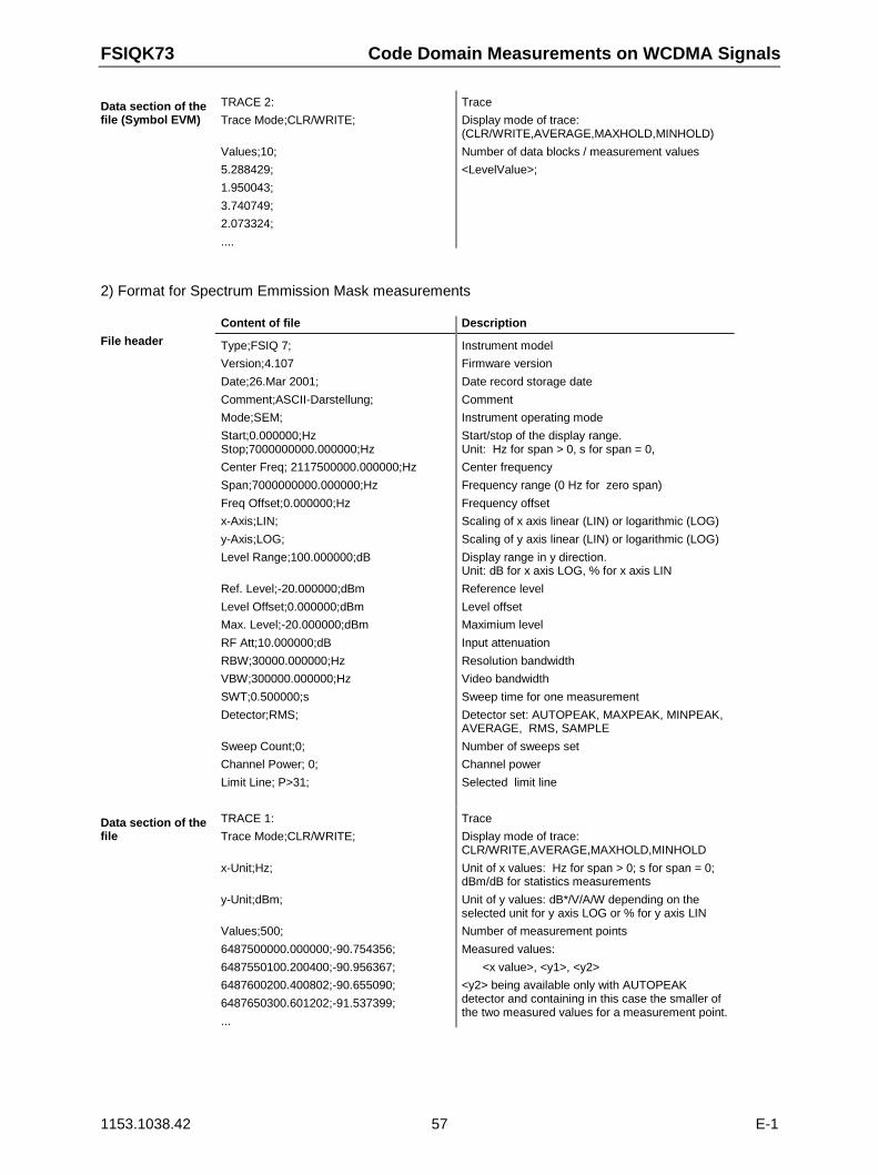
FSIQK73 Code Domain Measurements on WCDMA Signals
1153.1038.42 57 E-1
Data section of thefile (Symbol EVM)
TRACE 2:
Trace Mode;CLR/WRITE;
Values;10;
5.288429;
1.950043;
3.740749;
2.073324;
....
Trace
Display mode of trace:(CLR/WRITE,AVERAGE,MAXHOLD,MINHOLD)
Number of data blocks / measurement values
<LevelValue>;
2) Format for Spectrum Emmission Mask measurements
Content of file Description
File header Type;FSIQ 7;
Version;4.107
Date;26.Mar 2001;
Comment;ASCII-Darstellung;
Mode;SEM;
Start;0.000000;HzStop;7000000000.000000;Hz
Center Freq; 2117500000.000000;Hz
Span;7000000000.000000;Hz
Freq Offset;0.000000;Hz
x-Axis;LIN;
y-Axis;LOG;
Level Range;100.000000;dB
Ref. Level;-20.000000;dBm
Level Offset;0.000000;dBm
Max. Level;-20.000000;dBm
RF Att;10.000000;dB
RBW;30000.000000;Hz
VBW;300000.000000;Hz
SWT;0.500000;s
Detector;RMS;
Sweep Count;0;
Channel Power; 0;
Limit Line; P>31;
Instrument model
Firmware version
Date record storage date
Comment
Instrument operating mode
Start/stop of the display range.Unit: Hz for span > 0, s for span = 0,
Center frequency
Frequency range (0 Hz for zero span)
Frequency offset
Scaling of x axis linear (LIN) or logarithmic (LOG)
Scaling of y axis linear (LIN) or logarithmic (LOG)
Display range in y direction.Unit: dB for x axis LOG, % for x axis LIN
Reference level
Level offset
Maximium level
Input attenuation
Resolution bandwidth
Video bandwidth
Sweep time for one measurement
Detector set: AUTOPEAK, MAXPEAK, MINPEAK,AVERAGE, RMS, SAMPLE
Number of sweeps set
Channel power
Selected limit line
Data section of thefile
TRACE 1:
Trace Mode;CLR/WRITE;
x-Unit;Hz;
y-Unit;dBm;
Values;500;
6487500000.000000;-90.754356;
6487550100.200400;-90.956367;
6487600200.400802;-90.655090;
6487650300.601202;-91.537399;
...
Trace
Display mode of trace:CLR/WRITE,AVERAGE,MAXHOLD,MINHOLD
Unit of x values: Hz for span > 0; s for span = 0;dBm/dB for statistics measurements
Unit of y values: dB*/V/A/W depending on theselected unit for y axis LOG or % for y axis LIN
Number of measurement points
Measured values:
<x value>, <y1>, <y2>
<y2> being available only with AUTOPEAKdetector and containing in this case the smaller ofthe two measured values for a measurement point.
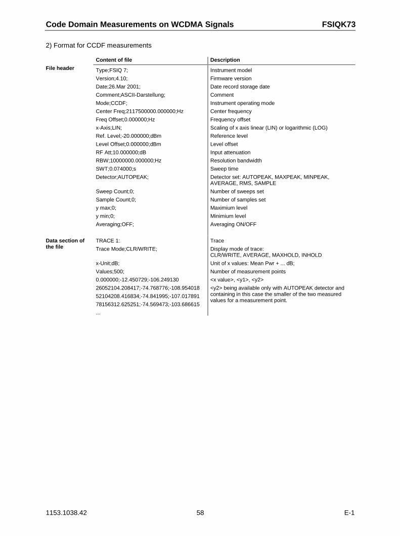
Code Domain Measurements on WCDMA Signals FSIQK73
1153.1038.42 58 E-1
2) Format for CCDF measurements
Content of file Description
File header Type;FSIQ 7;
Version;4.10;
Date;26.Mar 2001;
Comment;ASCII-Darstellung;
Mode;CCDF;
Center Freq;2117500000.000000;Hz
Freq Offset;0.000000;Hz
x-Axis;LIN;
Ref. Level;-20.000000;dBm
Level Offset;0.000000;dBm
RF Att;10.000000;dB
RBW;10000000.000000;Hz
SWT;0.074000;s
Detector;AUTOPEAK;
Sweep Count;0;
Sample Count;0;
y max;0;
y min;0;
Averaging;OFF;
Instrument model
Firmware version
Date record storage date
Comment
Instrument operating mode
Center frequency
Frequency offset
Scaling of x axis linear (LIN) or logarithmic (LOG)
Reference level
Level offset
Input attenuation
Resolution bandwidth
Sweep time
Detector set: AUTOPEAK, MAXPEAK, MINPEAK,AVERAGE, RMS, SAMPLE
Number of sweeps set
Number of samples set
Maximium level
Minimium level
Averaging ON/OFF
Data section ofthe file
TRACE 1:
Trace Mode;CLR/WRITE;
x-Unit;dB;
Values;500;
0.000000;-12.450729;-106.249130
26052104.208417;-74.768776;-108.954018
52104208.416834;-74.841995;-107.017891
78156312.625251;-74.569473;-103.686615
...
Trace
Display mode of trace:CLR/WRITE, AVERAGE, MAXHOLD, INHOLD
Unit of x values: Mean Pwr + ... dB;
Number of measurement points
<x value>, <y1>, <y2>
<y2> being available only with AUTOPEAK detector andcontaining in this case the smaller of the two measuredvalues for a measurement point.
FSIQK73 Overview of Other Menus
1153.1038.42 59 E-1
Overview of Other Menus
SYSTEM Key Group
The PRESET; CAL and INFO menus in the code domain measurement mode are identical to thecorresponding menus in the basic unit and are described in the FSIQ operating manual.
The parameters marked with grey are not available in the DISPLAY menu. The screen display is set toSPLIT SCREEN in the code domain measurement mode. The remaining softkeys are identical to thoseof the basic unit and are described in the FSIQ operating manual.
CONFIGURATION Key Group
The MODE menu enables selection of the mode. The analyzer, vector analyzer and tracking generatormodes are described in the operating manual for the FSIQ basic unit. The code domain measurementmode is described in the present manual.
The SETUP menu in the code domain measurement mode is identical to the corresponding menu in thebasic unit and is described in the FSIQ operating manual.
FREQUENCY Key Group
In the CENTER menu, the center frequency can be set for synchronization with the DUT and afrequency offset entered.
The SPAN, START and STOP keys have no function in the code domain measurement mode.
LEVEL Key Group, INPUT Key
The REF, RANGE and INPUT menus in the code domain measurement mode are identical to thecorresponding menus in the basic unit and are described in the FSIQ operating manual.
MARKER Key Group
The NORMAL menu in the code domain measurement mode is identical to the CONFIGURATIONMODE – 3GPP MS ANALYZER – CODE DOM POWER submenu.
The DELTA menu in the code domain measurement mode is identical to the corresponding menu in thevector analyzer mode and is described in the FSIQ operating manual.
The SEARCH and MKR → keys have no function in the code domain measurement mode.
LINES Key Group
The LIMIT LINES and D-LINES keys have no function in the code domain measurement mode.
Overview of Other Menus FSIQK73
1153.1038.42 60 E-1
SWEEP Key Group
The softkeys FREE RUN, EXTERN, TRIGGER OFFSET and SLOPE POS/NEG are available in theTRIGGER menu.
In the SWEEP menu only the parameters SINGLE SWEEP and CONTINUOUS SWEEP are available.
The COUPLING key has no function in the code domain measurement mode.
HCOPY and MEMORY Key Group
The SETTINGS, RECALL and CONFIG menus in the code-domain measurement mode are identical tothe corresponding menus in the basic unit and are described in the FSIQ operating manual.
The SAVE menu offers the possibility to store the WCDMA channel tables. To this end, selection"WCDMA channel table" is included in the ITEMS TO SAVE selection list. The corresponding data setfile has the extension *.ctm.
FSIQK73 Remote-Control Commands
1153.1038.42 61 E-1
7 Remote-Control Commands
The following chapter describes the remote-control commands for the application firmware. Analphabetical list at the end of this chapter provides an overview of the commands.
The commands, which are also valid for the basic unit in the signal analyzer and vector signal analyzermodes as well as the system settings, are described in the operating manual of the analyzer.
CALCulate Subsystem
:CALCulate<1|2>:FEED <string>
This command selects the measured data that are to be displayed. .
Parameter: <string>::= ‘XPOW:CDP’ |‘XPOW:CDP:RAT’ |‘XPOW:CDP:OVERview’ |‘XTIM:CDP:MACCuracy’ |‘XTIM:CDP:PVSLot’ |‘XTIM:CDP:BSTReam’ |‘XTIM:CDP:ERR:SUMM’ |‘XTIM:CDP:ERR:CTABle’ |‘XTIM:CDP:ERR:PCDomain‘ |‘XTIM:CDP:SYMB:CONStellation‘ |‘XTIM:CDP:SYMB:EVM‘
Example: ":CALC2:FEED ‘XTIM:CDP:MACCuracy’"
Features: *RST value: ‘XTIM:DDEM:MEAS’ (vector signal analysis)SCPI: conforming
Note: For code domain power (CDP) measurements, the display is always operated in the SPLITSCREEN mode and the assignment of display mode to measurement window is fixed.Therefore, the numeric suffix that is required or permitted is given in brackets for eachdisplay mode.
The string parameters have the following meaning:
‘XPOW:CDP’ Result display of code domain power as bargraph(CALCulate<1>)
‘XPOW:CDP:RAT’ Result display of code domain power ratio as bargraph(CALCulate<1>)
‘XPOW:CDP:OVERview' overview, screen A displays CDP Rel I,screen B CDP Q
‘XTIM:CDP:ERR:SUMM’ Result display in tabular form (CALCulate2)‘XTIM:CDP:ERR:CTABle’ Result display of channel assignment table (CALCulate<1>)‘XTIM:CDP:ERR:PCDomain’ Result display of peak code domain error (CALCulate2)‘XTIM:CDP:MACCuracy’ Result display of modulation accuracy (error vector magnitude
referred to the overall signal) (CALCulate2)‘XTIM:CDP:PVSLot’ Result display of power versus slot (CALCulate2)‘XTIM:CDP:BSTReam’ Result display of bit stream (CALCulate2)‘XTIM:CDP:SYMB:CONStellation’ Result display of symbol constellation (CALCulate2)‘XTIM:CDP:SYMB:EVM’ Result display of symbol error vector magnitude (CALCulate2)
Remote-Control Commands FSIQK73
1153.1038.42 62 E-1
:CALCulate:LIMit:ESPectrum:MODE AUTO | USER
This command switches on or off the automatic selection of limit lines for spectrum emission maskmeasurements.
Parameter: AUTO the set limit line depends on the measured channel powerUSER only query possible, user-defined limit lines are switched on
(see manual of instrument for description of limit line functions)
Example: ":CALC:LIM:ESP:MODE AUTO"
Features: *RST value: AUTOSCPI: device-specific
:CALCulate<1|2>:MARKer<1>:FUNCtion:DPCCh
This command sets the marker1 to channel 1.
Example: ":CALC:MARK:FUNC:DPCC"
Features: *RST value: _SCPI: device-specific
This command is an <Event> and has therefore neither *RST value nor query. Only the numericsuffix 1 is permissible in MARKer.
The numeric suffix in CALCulate that is required or permissible depends on the selected displaymode for which the marker is to be valid and has to coincide with it:
CALCulate<1> for CDP absolute and relative
CALCulate2 for modulation accuracy, peak code domain error, power versus slot, bit stream,symbol constellation and EVM
CALCulate<1>:MARKer<1>:FUNCtion:CRESt?Queries the Crest factor in the time domain measurement. Only the numeric suffix 1 is permissible inCALCulate and MARKer.
Example: "CALC:MARK:FUNC:CRES?"
Features: *RST value: --SCPI: device-specific
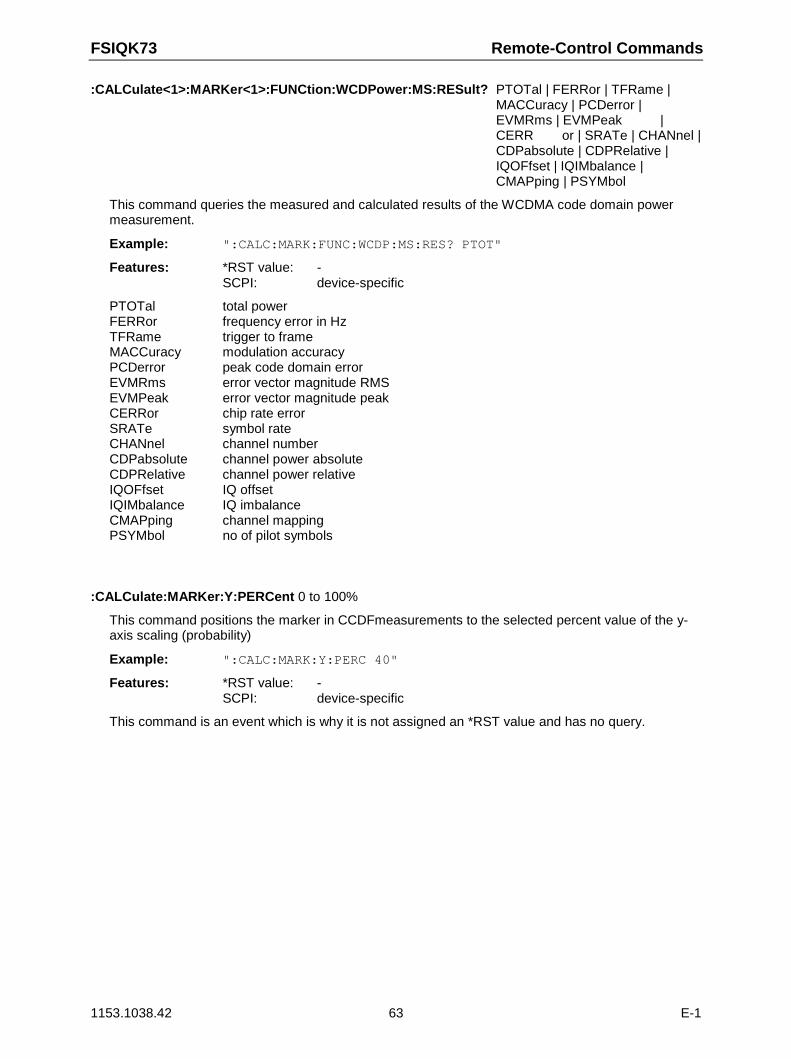
FSIQK73 Remote-Control Commands
1153.1038.42 63 E-1
:CALCulate<1>:MARKer<1>:FUNCtion:WCDPower:MS:RESult? PTOTal | FERRor | TFRame |MACCuracy | PCDerror |EVMRms | EVMPeak |CERR or | SRATe | CHANnel |CDPabsolute | CDPRelative |IQOFfset | IQIMbalance |CMAPping | PSYMbol
This command queries the measured and calculated results of the WCDMA code domain powermeasurement.
Example: ":CALC:MARK:FUNC:WCDP:MS:RES? PTOT"
Features: *RST value: -SCPI: device-specific
PTOTal total powerFERRor frequency error in HzTFRame trigger to frameMACCuracy modulation accuracyPCDerror peak code domain errorEVMRms error vector magnitude RMSEVMPeak error vector magnitude peakCERRor chip rate errorSRATe symbol rateCHANnel channel numberCDPabsolute channel power absoluteCDPRelative channel power relativeIQOFfset IQ offsetIQIMbalance IQ imbalanceCMAPping channel mappingPSYMbol no of pilot symbols
:CALCulate:MARKer:Y:PERCent 0 to 100%
This command positions the marker in CCDFmeasurements to the selected percent value of the y-axis scaling (probability)
Example: ":CALC:MARK:Y:PERC 40"
Features: *RST value: -SCPI: device-specific
This command is an event which is why it is not assigned an *RST value and has no query.
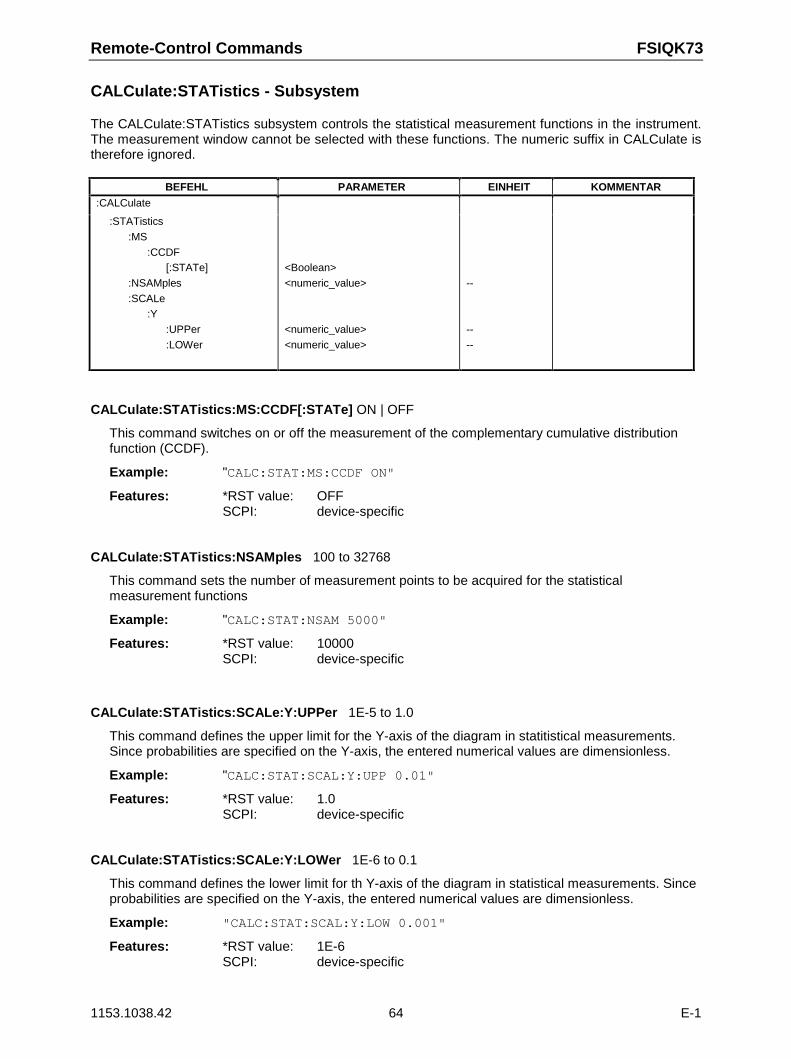
Remote-Control Commands FSIQK73
1153.1038.42 64 E-1
CALCulate:STATistics - Subsystem
The CALCulate:STATistics subsystem controls the statistical measurement functions in the instrument.The measurement window cannot be selected with these functions. The numeric suffix in CALCulate istherefore ignored.
BEFEHL PARAMETER EINHEIT KOMMENTAR
:CALCulate
:STATistics
:MS
:CCDF[:STATe]
:NSAMples
:SCALe:Y
:UPPer
:LOWer
<Boolean>
<numeric_value>
<numeric_value>
<numeric_value>
--
--
--
CALCulate:STATistics:MS:CCDF[:STATe] ON | OFF
This command switches on or off the measurement of the complementary cumulative distributionfunction (CCDF).
Example: "CALC:STAT:MS:CCDF ON"
Features: *RST value: OFFSCPI: device-specific
CALCulate:STATistics:NSAMples 100 to 32768
This command sets the number of measurement points to be acquired for the statisticalmeasurement functions
Example: "CALC:STAT:NSAM 5000"
Features: *RST value: 10000SCPI: device-specific
CALCulate:STATistics:SCALe:Y:UPPer 1E-5 to 1.0
This command defines the upper limit for the Y-axis of the diagram in statitistical measurements.Since probabilities are specified on the Y-axis, the entered numerical values are dimensionless.
Example: "CALC:STAT:SCAL:Y:UPP 0.01"
Features: *RST value: 1.0SCPI: device-specific
CALCulate:STATistics:SCALe:Y:LOWer 1E-6 to 0.1
This command defines the lower limit for th Y-axis of the diagram in statistical measurements. Sinceprobabilities are specified on the Y-axis, the entered numerical values are dimensionless.
Example: "CALC:STAT:SCAL:Y:LOW 0.001"
Features: *RST value: 1E-6SCPI: device-specific
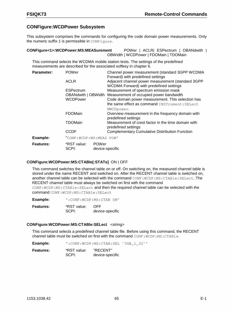
FSIQK73 Remote-Control Commands
1153.1038.42 65 E-1
CONFigure:WCDPower Subsystem
This subsystem comprises the commands for configuring the code domain power measurements. Onlythe numeric suffix 1 is permissible in CONFigure.
CONFigure<1>:WCDPower:MS:MEASurement POWer | ACLR| ESPectrum | OBANdwith |OBWidth | WCDPower | FDOMain | TDOMain
This command selects the WCDMA mobile station tests. The settings of the predefinedmeasurements are described for the associated softkey in chapter 6.
Parameter: POWer Channel power measurement (standard 3GPP WCDMA Forward) with predefined settings
ACLR Adjacent channel power measurement (standard 3GPPWCDMA Forward) with predefined settings
ESPectrum Measurement of spectrum emission maskOBANdwith | OBWidth Measurement of occupied power bandwidthWCDPower Code domain power measurement. This selection has
the same effect as command INSTrument:SELect MWCDpower.
FDOMain Overview measurement in the frequency domain with predefined settings
TDOMain Measurement of crest factor in the time domain withpredefined settings
CCDF Complementary Cumulative Distribution Function
Example: "CONF:WCDP:MS:MEAS POW"
Features: *RST value: POWerSCPI: device-specific
CONFigure:WCDPower:MS:CTABle[:STATe] ON | OFF
This command switches the channel table on or off. On switching on, the measured channel table isstored under the name RECENT and switched on. After the RECENT channel table is switched on,another channel table can be selected with the command CONF:WCDP:MS:CTABle:SELect. TheRECENT channel table must always be switched on first with the commandCONF:WCDP:MS:CTABle:SELect and then the required channel table can be selected with thecommand CONF:WCDP:MS:CTABle:SELect
Example: ":CONF:WCDP:MS:CTAB ON"
Features: *RST value: OFFSCPI: device-specific
CONFigure:WCDPower:MS:CTABle:SELect <string>
This command selects a predefined channel table file. Before using this command, the RECENTchannel table must be switched on first with the command CONF:WCDP:MS:CTABle.
Example: ":CONF:WCDP:MS:CTAB:SEL ’3GB_1_32’"
Features: *RST value: "RECENT"SCPI: device-specific
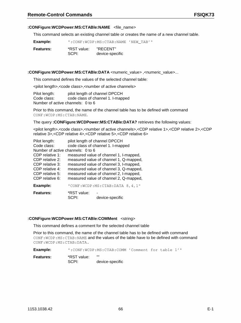
Remote-Control Commands FSIQK73
1153.1038.42 66 E-1
:CONFigure:WCDPower:MS:CTABle:NAME <file_name>
This command selects an existing channel table or creates the name of a new channel table.
Example: ":CONF:WCDP:MS:CTAB:NAME ’NEW_TAB’"
Features: *RST value: "RECENT"SCPI: device-specific
:CONFigure:WCDPower:MS:CTABle:DATA <numeric_value> ,<numeric_value>...
This command defines the values of the selected channel table:
<pilot length>,<code class>,<number of active channels>
Pilot length: pilot length of channel DPCCHCode class: code class of channel 1. I-mappedNumber of active channels: 0 to 6
Prior to this command, the name of the channel table has to be defined with commandCONF:WCDP:MS:CTAB:NAME.
The query :CONFigure:WCDPower:MS:CTABle:DATA? retrieves the following values:
<pilot length>,<code class>,<number of active channels>,<CDP relative 1>,<CDP relative 2>,<CDPrelative 3>,<CDP relative 4>,<CDP relative 5>,<CDP relative 6>
Pilot length: pilot length of channel DPCCHCode class: code class of channel 1. I-mappedNumber of active channels: 0 to 6CDP relative 1: measured value of channel 1, I-mapped,CDP relative 2: measured value of channel 1, Q-mapped,CDP relative 3: measured value of channel 3, I-mapped,CDP relative 4: measured value of channel 3, Q-mapped,CDP relative 5: measured value of channel 2, I-mapped,CDP relative 6: measured value of channel 2, Q-mapped,
Example: "CONF:WCDP:MS:CTAB:DATA 8,4,1"
Features: *RST value: -SCPI: device-specific
:CONFigure:WCDPower:MS:CTABle:COMMent <string>
This command defines a comment for the selected channel table
Prior to this command, the name of the channel table has to be defined with commandCONF:WCDP:MS:CTAB:NAME and the values of the table have to be defined with commandCONF:WCDP:MS:CTAB:DATA.
Example: ":CONF:WCDP:MS:CTAB:COMM ’Comment for table 1’"
Features: *RST value: ""SCPI: device-specific
FSIQK73 Remote-Control Commands
1153.1038.42 67 E-1
:CONFigure:WCDPower:MS:CTABle:COPY <file_name>
This command copies one channel table onto another one. The channel table to be copied isselected with command CONF:WCDP:MS:CTAB:NAME.
Parameter: <file_name> ::= name of the new channel table
Example: ":CONF:WCDP:MS:CTAB:COPY ’CTAB_2’"
Features: *RST value: --SCPI: device-specific
The name of the channel table may contain a maximum of 8 characters. This command is an "event"which is why it is not assigned an *RST value and has no query.
:CONFigure:WCDPower:MS:CTABle:DELete
This command deletes the selected channel table. The channel table to be deleted is selected withcommand CONF:WCDP:MS:CTAB:NAME.
Example: ":CONF:WCDP:MS:CTAB:DEL"
Features: *RST value: --SCPI: device-specific
This command is an "event" which is why it is not assigned an *RST value and has no query.
:CONFigure:WCDPower:MS:CTABle:CATalog?
This command reads out the names of all channel tables stored on the harddisk.
Syntax of output format:
<Sum of file lengths of all subsequent files>,<free memory on hard disk>,<1st file name>,,<1st file length>,<2nd file name>,,<2nd file length>,....,<nth file name>,<nth file length>
Example: ":CONF:WCDP:MS:CTAB:CAT?"
Features: *RST value: --SCPI: device-specific
INSTrument Subsystem
:INSTrument[:SELect] SANalyzer | DDEMod | ADEMod | BGSM | MSGM | CDPower |BWCDpower|WCDPower | MWCDpower
This command switches between the operating modes by means of text parameters.
Selection MWCDpower presets the instrument as described in Chapter 2, Section "Basic Settings inCode Domain Measurement Mode".
Example: ":INST MWCD"
Features: *RST value: SANalyzerSCPI: conforming
Remote-Control Commands FSIQK73
1153.1038.42 68 E-1
SENSe:CDPower Subsystem
This subsystem controls the parameters for the code domain mode. The numeric suffix in SENSe<1|2>is not significant in this subsystem.
:[SENSe:]CDPower:SFACtor 4 | 8 | 16 | 32 | 64 | 128 | 256
This command defines the spreading factor. The spreading factor is only significant for display modePEAK CODE DOMAIN ERROR.
Example: "CDP:SFACtor 16"
Features: *RST value: 256SCPI: device-specific
:[SENSe:]CDPower:CODE 0 to 255
This command sets the code number. The code number refers to code class 8 (spreading factor256).
Example: ":CDP:CODE 30"
Features: *RST value: 0SCPI: device-specific
:[SENSe:]CDPower:MAPPing I | Q
This command defines the mapping of thes CDP signal.
Example: ":CDP:MAPP I"
Features: *RST value: ISCPI: device-specific
:[SENSe:]CDPower:NORMalize ON | OFF
This command switches normalization of the unit circle with the IQ offset on or off.
Example: ":CDP:NORM OFF"
Features: *RST value: OFFSCPI: device-specific
Mode: WCDP
:[SENSe:]CDPower:SLOT 0 to 14
This command sets the slot number.
Example: ":CDP:SLOT 3"
Features: *RST value: 0SCPI: device-specific
FSIQK73 Remote-Control Commands
1153.1038.42 69 E-1
:[SENSe:]CDPower:PRESet
This command sets the parameters of the WCDMA measurement to predefined values (see softkeyCDP AUTO ADJUST in chapter 6).
Example: ":CDP:PRES"
Features: *RST value: -SCPI: device-specific
This command is an <Event> and has therefore neither *RST value nor query.
:[SENSe:]CDPower:SBANd NORMal | INVers
This command is for interchanging the left and the right sideband.
Example: ":CDP:CDP:SBAN INV"
Features: *RST value: INVSCPI: device-specific
Mode: WCDP
:[SENSe:]CDPower:LCODe[:VALue] #H0 to #H1fff (hex)
This command defines the scrambling code in hexadecimal format.
Example: ":CDP:LCOD #H2"
Features: *RST value: 0SCPI: device-specific
:[SENSe>:]CDPower:LCODe:TYPE LONG | SHORt
This command switches between long and short scrambling code.
Example: ":CDP:LCOD:TYPE SHOR"
Features: *RST value: LONGSCPI: device-specific
:[SENSe:]CDPower:ICTReshold -50 dB to + 10 dB
This command sets the threshold value from which a channel is treated as active. The level enteredrefers to the total signal power.
Example: ":CDP:ICTR –10DB"
Features: *RST value: -10 dBSCPI: device-specific
:[SENSe:]CDPower:LEVel:ADJust
This command is used for setting automatically the RF attenuation and IF gain to the level of theapplied signal. The instrument is to be switched to the ATTEN MANUAL mode so as to set the RFattenuation and IF gain separately to optimum values. This mode is maintained after changing fromcode domain power measurements to the analyzer or vector analyzer modes.
Example: ":CDP:LEV:ADJ"
Features: *RST value: -SCPI: device-specific
This command is an <Event> and has therefore neither *RST value nor query.
Remote-Control Commands FSIQK73
1153.1038.42 70 E-1
TRACe Subsystem
TRACe[:DATA] TRACE1 | TRACE2 | ABITstream
This command transfers trace data from the controller to the instrument, the query reads trace dataout of the instrument.
Example: ":TRAC TRACE1,"+A$ (A$: data list in current format)":TRAC? TRACE1"
Features: *RST value: -SCPI: conforming
Only TRACE1, TRACE2 or ABITstream can be queried depending on the display mode.
ABITstream can be set only if CALC2:FEED "XTIM:CDP:BSTReam" is selected (in the lowerbitstream window). This command returns the bitstreams of all 15 slots one after the other, theoutput format may be REAL, UINT or ASCIi.
For TRACE1 or TRACE2 the following measured values are transferred depending on the displaymode:
CODE PWR ABSOLUTE / RELATIVE (TRACE1) , CHANNEL TABLE (TRACE2)
Each channel is defined by the class, the channel number, the absolute level, the relative leveland the I/Q mapping. The class denotes the spreading factor of the channel.
Class 8 corresponds to the highest spreading factor (256, symbol rate 15 ksps), class 2 to thelowest admissible spreading factor (4, symbol rate 960 ksps).
Five values are transmitted for each channel.< class>,<cannel number>,<absolute level>,<relative level>,<I/Q mapping>, .....
The units are:
Absolute level dBm,Relative level dB referred to total power.I/Q mapping 1 = I mapping; 0 = Q mapping
The example shows the results of a query for three assigned channels with the followingconfiguration:
1st channel: spreading factor 256, channel number 0, Q-mapped
2nd channel: spreading factor 4, channel number 1, I-mapped
3rd channel: spreading factor 4, channel number 1, Q-mapped
This yields the following result: 8,0,-40,-20,0,0,2,1,-40,-20,1,2,7,1,-40,-20,0,0
The channels come in the same order as in the CDP diagram, i.e. depending on theirposition in the code domain of spreading factor 256.
RESULT SUMMARY (TRACE2)
The results of the RESULT SUMMARY are output in the following order:<modulation accuracy>,<peak CDE>,<carr freq Error>,<chip rate error>,<total power>,<trg to frame>,<EVM peak channel>,<EVM mean channel>, <class>,<channel number>,<power abs. channel>,<power rel. channel>,<I/Q mapping>,<number of pilot symbols>, <IQ offset>,<IQ imbalance>
The units are:EVM peak channel/mean channel, modulation accuracy, IQ offset/imbalance : %,Peak CDE, total power and power abs. channel dB.Power rel. Channel dB referred to total signal power.Carr freq error : HzChip Rate Error ppm.I/Q mapping 1 = I mapping; 0 = Q mappingPilot symbols absoluteTrg to Frame µs.
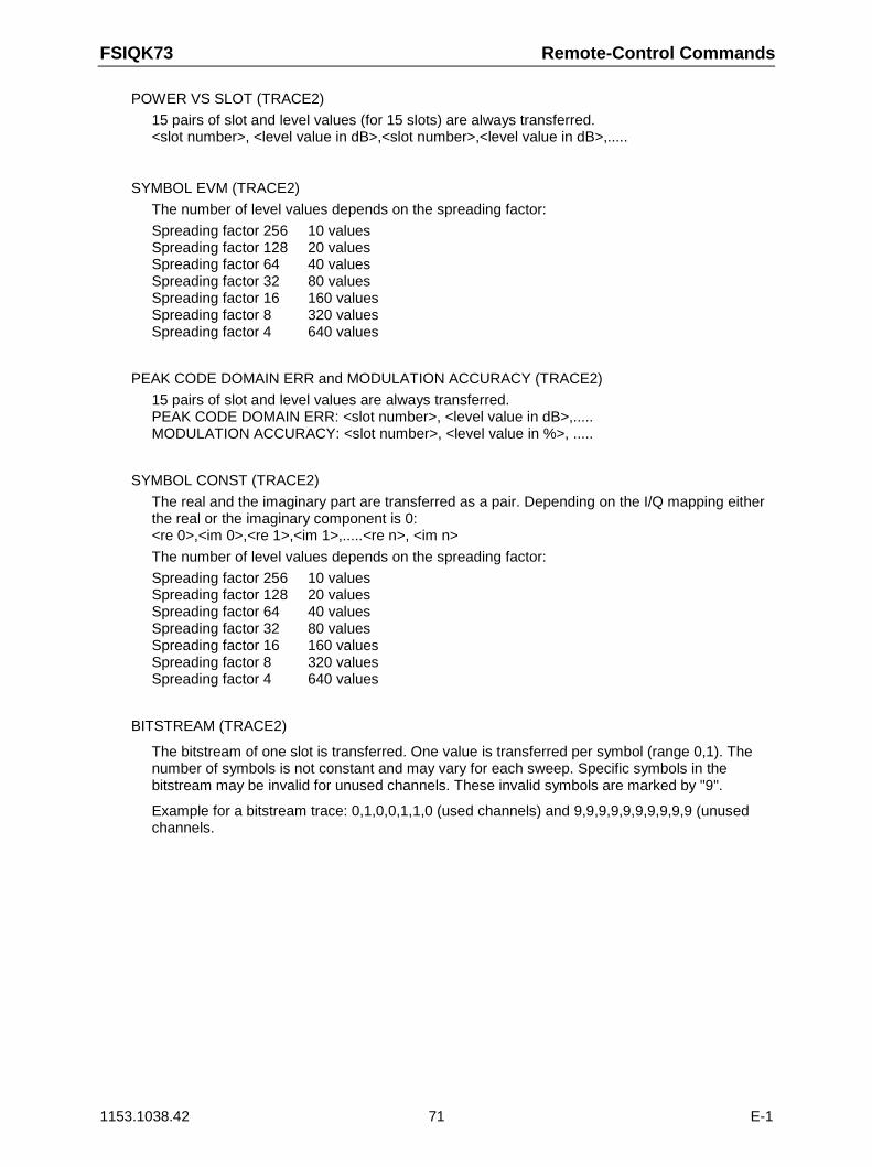
FSIQK73 Remote-Control Commands
1153.1038.42 71 E-1
POWER VS SLOT (TRACE2)
15 pairs of slot and level values (for 15 slots) are always transferred.<slot number>, <level value in dB>,<slot number>,<level value in dB>,.....
SYMBOL EVM (TRACE2)
The number of level values depends on the spreading factor:
Spreading factor 256 10 valuesSpreading factor 128 20 valuesSpreading factor 64 40 valuesSpreading factor 32 80 valuesSpreading factor 16 160 valuesSpreading factor 8 320 valuesSpreading factor 4 640 values
PEAK CODE DOMAIN ERR and MODULATION ACCURACY (TRACE2)
15 pairs of slot and level values are always transferred.PEAK CODE DOMAIN ERR: <slot number>, <level value in dB>,.....MODULATION ACCURACY: <slot number>, <level value in %>, .....
SYMBOL CONST (TRACE2)
The real and the imaginary part are transferred as a pair. Depending on the I/Q mapping eitherthe real or the imaginary component is 0:<re 0>,<im 0>,<re 1>,<im 1>,.....<re n>, <im n>
The number of level values depends on the spreading factor:
Spreading factor 256 10 valuesSpreading factor 128 20 valuesSpreading factor 64 40 valuesSpreading factor 32 80 valuesSpreading factor 16 160 valuesSpreading factor 8 320 valuesSpreading factor 4 640 values
BITSTREAM (TRACE2)
The bitstream of one slot is transferred. One value is transferred per symbol (range 0,1). Thenumber of symbols is not constant and may vary for each sweep. Specific symbols in thebitstream may be invalid for unused channels. These invalid symbols are marked by "9".
Example for a bitstream trace: 0,1,0,0,1,1,0 (used channels) and 9,9,9,9,9,9,9,9,9,9 (unusedchannels.
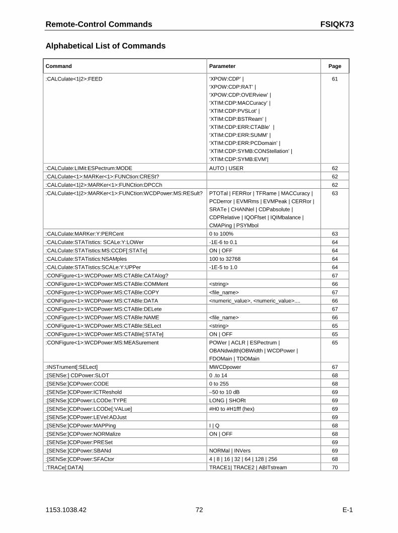
Remote-Control Commands FSIQK73
1153.1038.42 72 E-1
Alphabetical List of Commands
Command Parameter Page
:CALCulate<1|2>:FEED ‘XPOW:CDP’ |
‘XPOW:CDP:RAT’ |
‘XPOW:CDP:OVERview’ |
‘XTIM:CDP:MACCuracy’ |
‘XTIM:CDP:PVSLot’ |
‘XTIM:CDP:BSTReam’ |
‘XTIM:CDP:ERR:CTABle’ |
‘XTIM:CDP:ERR:SUMM’ |
‘XTIM:CDP:ERR:PCDomain’ |
‘XTIM:CDP:SYMB:CONStellation’ |
‘XTIM:CDP:SYMB:EVM’|
61
:CALCulate:LIMit:ESPectrum:MODE AUTO | USER 62
:CALCulate<1>:MARKer<1>:FUNCtion:CRESt? 62
:CALCulate<1|2>:MARKer<1>:FUNCtion:DPCCh 62
:CALCulate<1|2>:MARKer<1>:FUNCtion:WCDPower:MS:RESult? PTOTal | FERRor | TFRame | MACCuracy |
PCDerror | EVMRms | EVMPeak | CERRor |
SRATe | CHANNel | CDPabsolute |
CDPRelative | IQOFfset | IQIMbalance |
CMAPing | PSYMbol
63
:CALCulate:MARKer:Y:PERCent 0 to 100% 63
:CALCulate:STATistics: SCALe:Y:LOWer -1E-6 to 0.1 64
:CALCulate:STATistics:MS:CCDF[:STATe] ON | OFF 64
:CALCulate:STATistics:NSAMples 100 to 32768 64
:CALCulate:STATistics:SCALe:Y:UPPer -1E-5 to 1.0 64
:CONFigure<1>:WCDPower:MS:CTABle:CATAlog? 67
:CONFigure<1>:WCDPower:MS:CTABle:COMMent <string> 66
:CONFigure<1>:WCDPower:MS:CTABle:COPY <file_name> 67
:CONFigure<1>:WCDPower:MS:CTABle:DATA <numeric_value>, <numeric_value>.... 66
:CONFigure<1>:WCDPower:MS:CTABle:DELete 67
:CONFigure<1>:WCDPower:MS:CTABle:NAME <file_name> 66
:CONFigure<1>:WCDPower:MS:CTABle:SELect <string> 65
:CONFigure<1>:WCDPower:MS:CTABle[:STATe] ON | OFF 65
:CONFigure<1>:WCDPower:MS:MEASurement POWer | ACLR | ESPectrum |
OBANdwidth|OBWidth | WCDPower |
FDOMain | TDOMain
65
:INSTrument[:SELect] MWCDpower 67
:[SENSe:] CDPower:SLOT 0 .to 14 68
:[SENSe:]CDPower:CODE 0 to 255 68
:[SENSe:]CDPower:ICTReshold –50 to 10 dB 69
:[SENSe:]CDPower:LCODe:TYPE LONG | SHORt 69
:[SENSe:]CDPower:LCODe[:VALue] #H0 to #H1fff (hex) 69
:[SENSe:]CDPower:LEVel:ADJust 69
:[SENSe:]CDPower:MAPPing I | Q 68
:[SENSe:]CDPower:NORMalize ON | OFF 68
:[SENSe:]CDPower:PRESet 69
:[SENSe:]CDPower:SBANd NORMal | INVers 69
:[SENSe:]CDPower:SFACtor 4 | 8 | 16 | 32 | 64 | 128 | 256 68
:TRACe[:DATA] TRACE1| TRACE2 | ABITstream 70
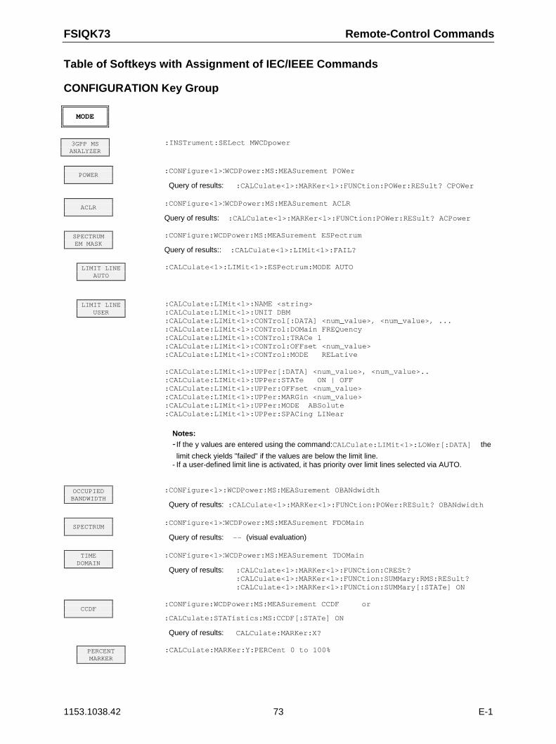
FSIQK73 Remote-Control Commands
1153.1038.42 73 E-1
Table of Softkeys with Assignment of IEC/IEEE Commands
CONFIGURATION Key Group
MODE
3GPP MSANALYZER
:INSTrument:SELect MWCDpower
POWER:CONFigure<1>:WCDPower:MS:MEASurement POWer
Query of results: :CALCulate<1>:MARKer<1>:FUNCtion:POWer:RESult? CPOWer
ACLR:CONFigure<1>:WCDPower:MS:MEASurement ACLR
Query of results: :CALCulate<1>:MARKer<1>:FUNCtion:POWer:RESult? ACPower
SPECTRUMEM MASK
:CONFigure:WCDPower:MS:MEASurement ESPectrum
Query of results:: :CALCulate<1>:LIMit<1>:FAIL?
LIMIT LINEAUTO
:CALCulate<1>:LIMit<1>:ESPectrum:MODE AUTO
LIMIT LINEUSER
:CALCulate:LIMit<1>:NAME <string>:CALCulate:LIMit<1>:UNIT DBM:CALCulate:LIMit<1>:CONTrol[:DATA] <num_value>, <num_value>, ...:CALCulate:LIMit<1>:CONTrol:DOMain FREQuency:CALCulate:LIMit<1>:CONTrol:TRACe 1:CALCulate:LIMit<1>:CONTrol:OFFset <num_value>:CALCulate:LIMit<1>:CONTrol:MODE RELative
:CALCulate:LIMit<1>:UPPer[:DATA] <num_value>, <num_value>..:CALCulate:LIMit<1>:UPPer:STATe ON | OFF:CALCulate:LIMit<1>:UPPer:OFFset <num_value>:CALCulate:LIMit<1>:UPPer:MARGin <num_value>:CALCulate:LIMit<1>:UPPer:MODE ABSolute:CALCulate:LIMit<1>:UPPer:SPACing LINear
Notes:- If the y values are entered using the command:CALCulate:LIMit<1>:LOWer[:DATA] the
limit check yields "failed" if the values are below the limit line.- If a user-defined limit line is activated, it has priority over limit lines selected via AUTO.
OCCUPIEDBANDWIDTH
:CONFigure<1>:WCDPower:MS:MEASurement OBANdwidth
Query of results: :CALCulate<1>:MARKer<1>:FUNCtion:POWer:RESult? OBANdwidth
SPECTRUM:CONFigure<1>:WCDPower:MS:MEASurement FDOMain
Query of results: -- (visual evaluation)
TIMEDOMAIN
:CONFigure<1>:WCDPower:MS:MEASurement TDOMain
Query of results: :CALCulate<1>:MARKer<1>:FUNCtion:CRESt?:CALCulate<1>:MARKer<1>:FUNCtion:SUMMary:RMS:RESult?:CALCulate<1>:MARKer<1>:FUNCtion:SUMMary[:STATe] ON
CCDF:CONFigure:WCDPower:MS:MEASurement CCDF or
:CALCulate:STATistics:MS:CCDF[:STATe] ON
Query of results: CALCulate:MARKer:X?
PERCENTMARKER
:CALCulate:MARKer:Y:PERCent 0 to 100%
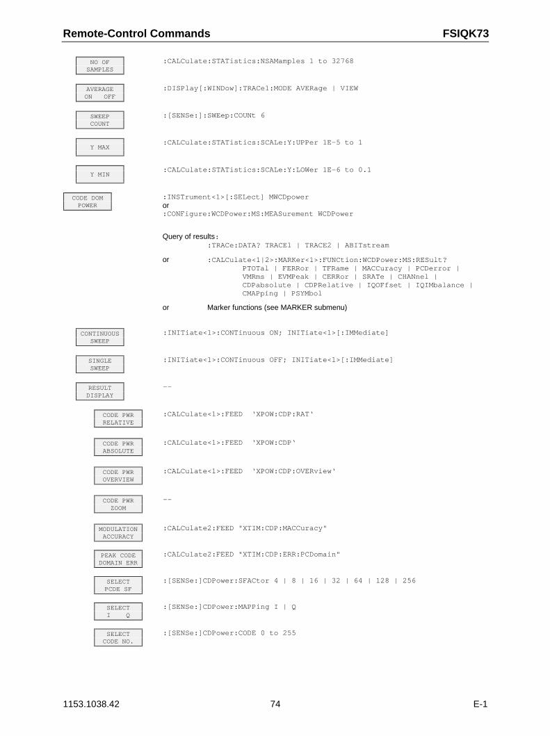
Remote-Control Commands FSIQK73
1153.1038.42 74 E-1
NO OFSAMPLES
:CALCulate:STATistics:NSAMamples 1 to 32768
AVERAGEON OFF
:DISPlay[:WINDow]:TRACe1:MODE AVERage | VIEW
SWEEPCOUNT
:[SENSe:]:SWEep:COUNt 6
Y MAX:CALCulate:STATistics:SCALe:Y:UPPer 1E-5 to 1
Y MIN:CALCulate:STATistics:SCALe:Y:LOWer 1E-6 to 0.1
CODE DOMPOWER
:INSTrument<1>[:SELect] MWCDpoweror:CONFigure:WCDPower:MS:MEASurement WCDPower
Query of results: :TRACe:DATA? TRACE1 | TRACE2 | ABITstream
or :CALCulate<1|2>:MARKer<1>:FUNCtion:WCDPower:MS:RESult? PTOTal | FERRor | TFRame | MACCuracy | PCDerror | VMRms | EVMPeak | CERRor | SRATe | CHANnel | CDPabsolute | CDPRelative | IQOFfset | IQIMbalance | CMAPping | PSYMbol
or Marker functions (see MARKER submenu)
CONTINUOUSSWEEP
:INITiate<1>:CONTinuous ON; INITiate<1>[:IMMediate]
SINGLESWEEP
:INITiate<1>:CONTinuous OFF; INITiate<1>[:IMMediate]
RESULTDISPLAY
--
CODE PWRRELATIVE
:CALCulate<1>:FEED ‘XPOW:CDP:RAT‘
CODE PWRABSOLUTE
:CALCulate<1>:FEED ‘XPOW:CDP‘
CODE PWROVERVIEW
:CALCulate<1>:FEED ‘XPOW:CDP:OVERview‘
CODE PWRZOOM
--
MODULATIONACCURACY
:CALCulate2:FEED "XTIM:CDP:MACCuracy"
PEAK CODEDOMAIN ERR
:CALCulate2:FEED "XTIM:CDP:ERR:PCDomain"
SELECTPCDE SF
:[SENSe:]CDPower:SFACtor 4 | 8 | 16 | 32 | 64 | 128 | 256
SELECTI Q
:[SENSe:]CDPower:MAPPing I | Q
SELECTCODE NO.
:[SENSe:]CDPower:CODE 0 to 255
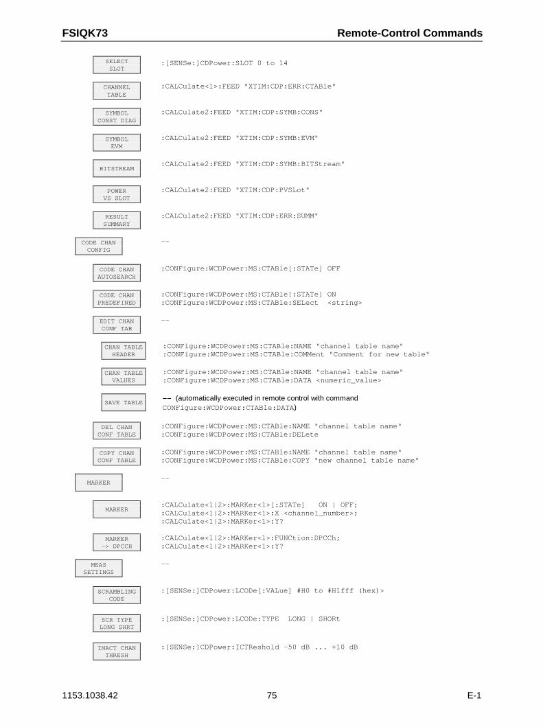
FSIQK73 Remote-Control Commands
1153.1038.42 75 E-1
SELECTSLOT
:[SENSe:]CDPower:SLOT 0 to 14
CHANNELTABLE
:CALCulate<1>:FEED "XTIM:CDP:ERR:CTABle"
SYMBOLCONST DIAG
:CALCulate2:FEED "XTIM:CDP:SYMB:CONS"
SYMBOLEVM
:CALCulate2:FEED "XTIM:CDP:SYMB:EVM"
BITSTREAM:CALCulate2:FEED "XTIM:CDP:SYMB:BITStream"
POWERVS SLOT
:CALCulate2:FEED "XTIM:CDP:PVSLot"
RESULTSUMMARY
:CALCulate2:FEED "XTIM:CDP:ERR:SUMM"
CODE CHANCONFIG
--
CODE CHANAUTOSEARCH
:CONFigure:WCDPower:MS:CTABle[:STATe] OFF
CODE CHANPREDEFINED
:CONFigure:WCDPower:MS:CTABle[:STATe] ON:CONFigure:WCDPower:MS:CTABle:SELect <string>
EDIT CHANCONF TAB
--
CHAN TABLEHEADER
:CONFigure:WCDPower:MS:CTABle:NAME "channel table name":CONFigure:WCDPower:MS:CTABle:COMMent "Comment for new table"
CHAN TABLEVALUES
:CONFigure:WCDPower:MS:CTABle:NAME "channel table name":CONFigure:WCDPower:MS:CTABle:DATA <numeric_value>
SAVE TABLE-- (automatically executed in remote control with commandCONFigure:WCDPower:CTABle:DATA)
DEL CHANCONF TABLE
:CONFigure:WCDPower:MS:CTABle:NAME "channel table name":CONFigure:WCDPower:MS:CTABle:DELete
COPY CHANCONF TABLE
:CONFigure:WCDPower:MS:CTABle:NAME "channel table name":CONFigure:WCDPower:MS:CTABle:COPY "new channel table name"
MARKER--
MARKER:CALCulate<1|2>:MARKer<1>[:STATe] ON | OFF;:CALCulate<1|2>:MARKer<1>:X <channel_number>;:CALCulate<1|2>:MARKer<1>:Y?
MARKER-> DPCCH
:CALCulate<1|2>:MARKer<1>:FUNCtion:DPCCh;:CALCulate<1|2>:MARKer<1>:Y?
MEASSETTINGS
--
SCRAMBLINGCODE
:[SENSe:]CDPower:LCODe[:VALue] #H0 to #H1fff (hex)>
SCR TYPELONG SHRT
:[SENSe:]CDPower:LCODe:TYPE LONG | SHORt
INACT CHANTHRESH
:[SENSe:]CDPower:ICTReshold -50 dB ... +10 dB
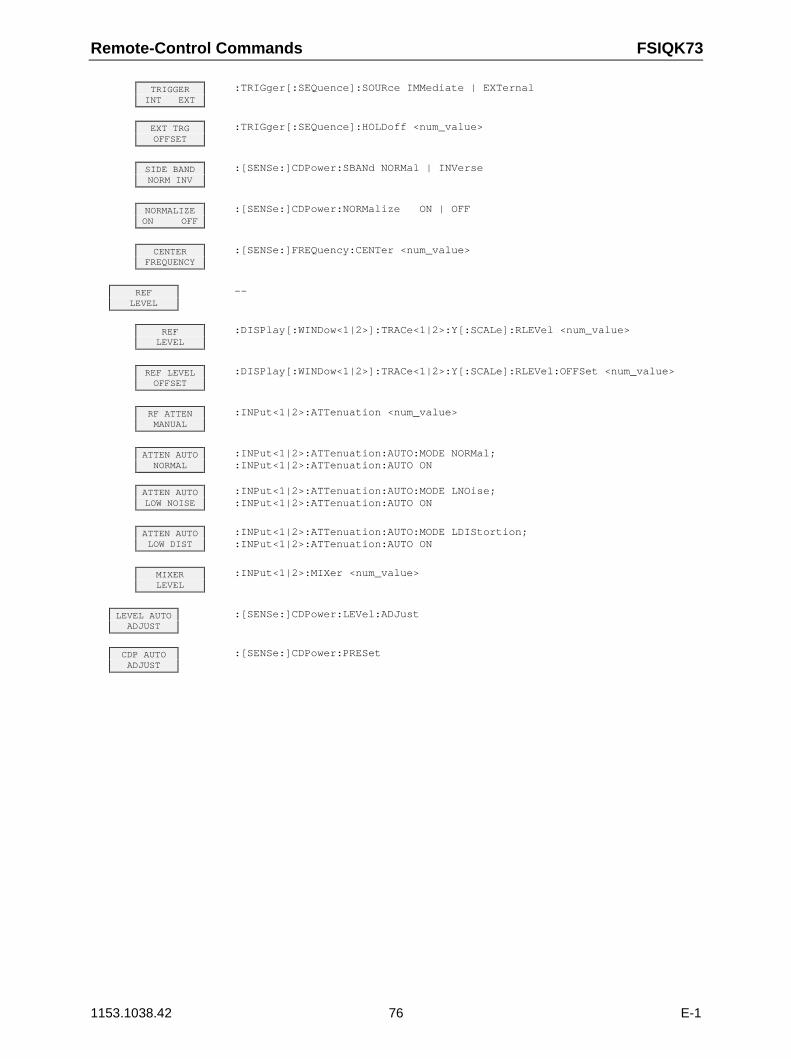
Remote-Control Commands FSIQK73
1153.1038.42 76 E-1
TRIGGERINT EXT
:TRIGger[:SEQuence]:SOURce IMMediate | EXTernal
EXT TRGOFFSET
:TRIGger[:SEQuence]:HOLDoff <num_value>
SIDE BANDNORM INV
:[SENSe:]CDPower:SBANd NORMal | INVerse
NORMALIZEON OFF
:[SENSe:]CDPower:NORMalize ON | OFF
CENTERFREQUENCY
:[SENSe:]FREQuency:CENTer <num_value>
REFLEVEL
--
REFLEVEL
:DISPlay[:WINDow<1|2>]:TRACe<1|2>:Y[:SCALe]:RLEVel <num_value>
REF LEVELOFFSET
:DISPlay[:WINDow<1|2>]:TRACe<1|2>:Y[:SCALe]:RLEVel:OFFSet <num_value>
RF ATTENMANUAL
:INPut<1|2>:ATTenuation <num_value>
ATTEN AUTONORMAL
:INPut<1|2>:ATTenuation:AUTO:MODE NORMal;:INPut<1|2>:ATTenuation:AUTO ON
ATTEN AUTOLOW NOISE
:INPut<1|2>:ATTenuation:AUTO:MODE LNOise;:INPut<1|2>:ATTenuation:AUTO ON
ATTEN AUTOLOW DIST
:INPut<1|2>:ATTenuation:AUTO:MODE LDIStortion;:INPut<1|2>:ATTenuation:AUTO ON
MIXERLEVEL
:INPut<1|2>:MIXer <num_value>
LEVEL AUTOADJUST
:[SENSe:]CDPower:LEVel:ADJust
CDP AUTOADJUST
:[SENSe:]CDPower:PRESet
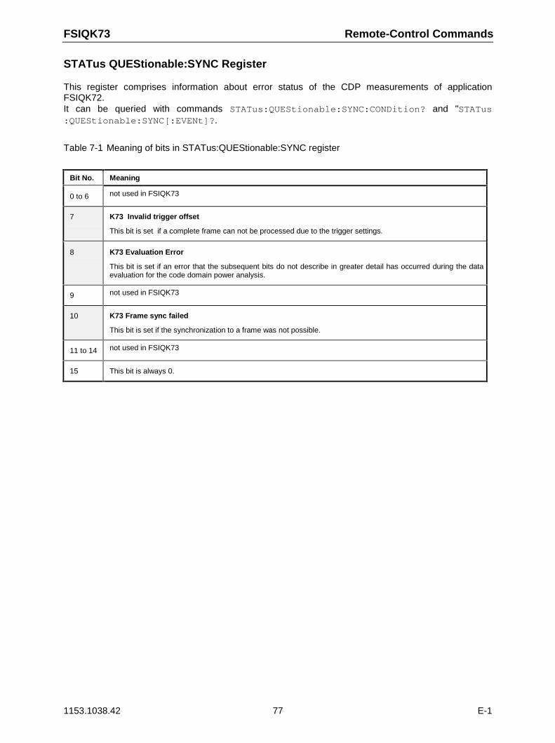
FSIQK73 Remote-Control Commands
1153.1038.42 77 E-1
STATus QUEStionable:SYNC Register
This register comprises information about error status of the CDP measurements of applicationFSIQK72.It can be queried with commands STATus:QUEStionable:SYNC:CONDition? and "STATus:QUEStionable:SYNC[:EVENt]?.
Table 7-1 Meaning of bits in STATus:QUEStionable:SYNC register
Bit No. Meaning
0 to 6 not used in FSIQK73
7 K73 Invalid trigger offset
This bit is set if a complete frame can not be processed due to the trigger settings.
8 K73 Evaluation Error
This bit is set if an error that the subsequent bits do not describe in greater detail has occurred during the dataevaluation for the code domain power analysis.
9 not used in FSIQK73
10 K73 Frame sync failed
This bit is set if the synchronization to a frame was not possible.
11 to 14 not used in FSIQK73
15 This bit is always 0.
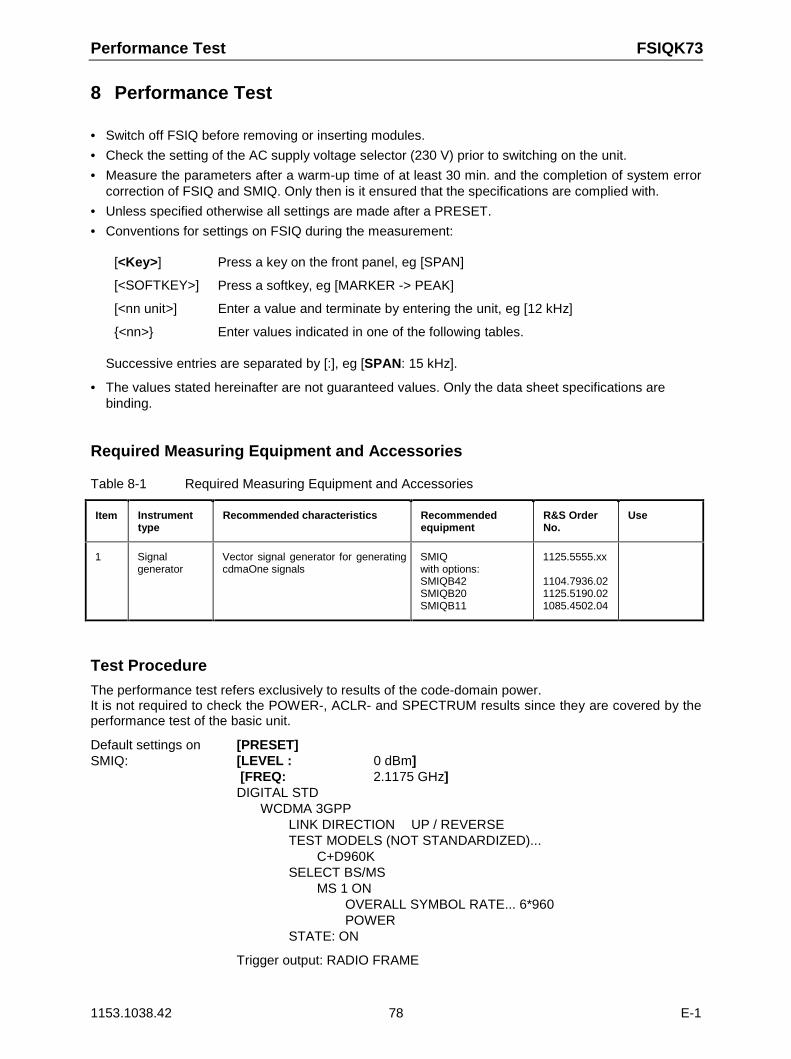
Performance Test FSIQK73
1153.1038.42 78 E-1
8 Performance Test
• Switch off FSIQ before removing or inserting modules.
• Check the setting of the AC supply voltage selector (230 V) prior to switching on the unit.
• Measure the parameters after a warm-up time of at least 30 min. and the completion of system errorcorrection of FSIQ and SMIQ. Only then is it ensured that the specifications are complied with.
• Unless specified otherwise all settings are made after a PRESET.
• Conventions for settings on FSIQ during the measurement:
[<Key>] Press a key on the front panel, eg [SPAN]
[<SOFTKEY>] Press a softkey, eg [MARKER -> PEAK]
[<nn unit>] Enter a value and terminate by entering the unit, eg [12 kHz]
<nn> Enter values indicated in one of the following tables.
Successive entries are separated by [:], eg [SPAN: 15 kHz].
• The values stated hereinafter are not guaranteed values. Only the data sheet specifications arebinding.
Required Measuring Equipment and Accessories
Table 8-1 Required Measuring Equipment and Accessories
Item Instrumenttype
Recommended characteristics Recommendedequipment
R&S OrderNo.
Use
1 Signalgenerator
Vector signal generator for generatingcdmaOne signals
SMIQwith options:SMIQB42SMIQB20SMIQB11
1125.5555.xx
1104.7936.021125.5190.021085.4502.04
Test Procedure
The performance test refers exclusively to results of the code-domain power.It is not required to check the POWER-, ACLR- and SPECTRUM results since they are covered by theperformance test of the basic unit.
Default settings onSMIQ:
[PRESET][LEVEL : 0 dBm] [FREQ: 2.1175 GHz]DIGITAL STD
WCDMA 3GPPLINK DIRECTION UP / REVERSETEST MODELS (NOT STANDARDIZED)...
C+D960KSELECT BS/MS
MS 1 ONOVERALL SYMBOL RATE... 6*960POWER
STATE: ON
Trigger output: RADIO FRAME
FSIQK73 Performance Test
1153.1038.42 79 E-1
Check set channels against the following table:
CHANNEL NUMBER 1 2 3 4 5 6
TYPE DPDCH DPDCH DPDCH DPDCH DPDCH DPDCH
SYMBOL RATE 960 960 960 960 960 960
CHAN CODE 1 1 3 3 2 2
DATA PN15 PN15 PN15 PN15 PN15 PN15
Default settings onFSIQ:
[PRESET][CENTER: 2.1175 GHz][REF: 10 dBm][MODE: 3GPP MS ANALYZER: CODE DOM POWERMEAS SETTINGS SCRAMBLING CODE 0
SCR TYPE LONGTRIGGER EXT
RESULT DISPLAY CHANNEL TABLE
Test setup and othersettings
SMIQ
FSIQ
Connect external trigger input of FSIQ to SMIQ
[TRIGGER: TRIGGER OFFSET: 0µs]
Connect external reference output of FSIQ to SMIQ
UTILITIESREF OSC
SOURCE: EXT
[SETUP: REFERENCE INT]
The display of the FSIQ should show the following:
Performance Test FSIQK73
1153.1038.42 80 E-1
START: CH 0 STOP: CH 25532 CH/DIV
Ref Lvl9 dBmRef Lvl9 dBmRef Lvl9 dBmRef Lvl9 dBm
A
CF 2.1175 GHzCode Pwr RelativeCode Pwr RelativeSlot Number 0Slot Number 0
SR 15 kspsChan Code 0Chan Code 0Mapping QMapping Q
-28
-21
dB
TRG
Ref Lvl9 dBmRef Lvl9 dBmRef Lvl9 dBmRef Lvl9 dBm
CF 2.1175 GHzChannel TableChannel TableSlot Number 0Slot Number 0
SR 15 kspsChan Code 0Chan Code 0Mapping QMapping Q
B
TRG
-63
-56
-49
-42
-35
-28
-21
-7
-70
0
CHANNEL TABLE
Type Symb R. Code # Status Mapping PWR ABS PWR REL©©©©©©©ª©©©©©©©©©©ª©©©©©©©©ª©©©©©©©©©ª©©©©©©©©©©ª©©©©©©©©©©ª©©©©©©©©©DPCCH 15 ksps 0 active Q -13.32 -6.99©©©©©©©ª©©©©©©©©©©ª©©©©©©©©ª©©©©©©©©©ª©©©©©©©©©©ª©©©©©©©©©©ª©©©©©©©©©DPDCH 960 ksps 1 active Q -13.32 -6.99DPDCH 960 ksps 1 active I -13.33 -7.00DPDCH 960 ksps 2 active Q -13.32 -7.00DPDCH 960 ksps 2 active I -13.32 -6.99DPDCH 960 ksps 3 active Q -13.31 -6.98DPDCH 960 ksps 3 active I -13.32 -6.99??? 15 ksps 0 inactv I -66.68 -60.35??? 15 ksps 1 inactv Q -65.60 -59.27??? 15 ksps 1 inactv I -66.55 -60.22??? 15 ksps 2 inactv Q -66.98 -60.66
Date: 5.JUL.2001 10:56:56
Transfer the measurement results indicated in the channel table to the performance test protocol.
FSIQK73 Performance Test
1153.1038.42 81 E-1
Performance Test Report
Note: The values specified in the data sheet are guaranteed limits. To these limits, the tolerances of theinstruments used in the performance test must be added because of their measurementuncertainty.
Table 8-2 Performance Test Report
Number pilot symbols: 8
Channel No.: Type Symbol rate Channel No.: Mapping
1 DPCCH 15 0 Q
2 DPDCH 960 1 I
3 DPDCH 960 1 Q
4 DPDCH 960 3 I
5 DPDCH 960 3 Q
6 DPDCH 960 2 I
7 DPDCH 960 2 Q
Glossary FSIQK73
1153.1038.42 82 E-1
9 Glossary
Crest-Faktor Ratio of peak to average value of the signal.
DPCCH Dedicated Physical Control Channel, control channel. Thechannel is used in the FSIQK73 for the synchronization of thesignal.
DPDCH Dedicated physical data channel, data channel. The datachannels which can be sent at different transmission rates areautomatically recognized during the measurement.
Inactive Channel Threshold Minimum power that a single channel must have as comparedto the total signal to be recognized as an active channel
Modulation Accuracy In accordance with the 3GPP specifications, the squared errorbetween the real and imaginary parts of the test signal and anideal reference signal is determined (EVM referred to the totalsignal) in a modulation accuracy measurement.
Peak Code Domain Error In accordance with the 3GPP specifications, the errorbetween the test signal and the ideal reference signal isprojected onto the classes of the different spreading factors inthe case of a peak code domain measurement.
FSIQK73 Index
1153.1038.42 83 E-1
10 Index
A
ACLR...............................................................................17ACP measurement ..........................................................17Adjacent-channel power ..................................................17Automatic search mode ...................................................43Automatic setting
CDP measurement ......................................................52
B
Bandwidthoccupied......................................................................20
Bitstream .........................................................................41
C
Carr Freq Err ...................................................................37CCDF
Contributive Cumulative Distribution Function .............24Center frequency .......................................................50, 59Chan Pow rel. / abs .........................................................38Channel assignment table ...............................................39Channel Code..................................................................38Channel table mode.........................................................44Channel, active..........................................................49, 82Chip Rate Err...................................................................37Code #.............................................................................39Code domain measurements ...........................................27Code domain power.........................................................30Commands
alphabetical list............................................................72assignment to softkey............................................19, 73description...................................................................61
Crest factor ......................................................................22
D
Dedicated Physical Common Control Channel.................47Default setting....................................................................3Display range of CCDF....................................................25Distribution function of signal amplitudes .........................24
E
Error Vector Mag rms / Pk ...............................................38External trigger ................................................................27
F
Frequency .......................................................................50offset ...........................................................................59
K
KeyCAL.............................................................................59CENTER .....................................................................59CONFIG ......................................................................60COUPLING .................................................................60DELTA ........................................................................59DISPLAY.....................................................................59DLINES .......................................................................59INFO ...........................................................................59INPUT .........................................................................59LIMITS ........................................................................59MKR TO ......................................................................59
MODE......................................................................... 15NORMAL .................................................................... 59PRESET ..................................................................... 59RANGE....................................................................... 59RECALL ..................................................................... 60REF ............................................................................ 59SAVE.......................................................................... 60SEARCH..................................................................... 59SETTINGS.................................................................. 60SETUP ....................................................................... 59SPAN.......................................................................... 59START........................................................................ 59STOP.......................................................................... 59SWEEP ...................................................................... 60TRACE ....................................................................... 53TRIGGER ................................................................... 60
M
Marker............................................................................. 47Menu overview................................................................ 13Mode
channel table .............................................................. 44code domain ............................................................... 27
Modulation accuracy ................................................. 34, 38
O
Offset, frequency............................................................. 59
P
Peak code domain error .................................................. 35Performance Test............................................................ 78Pk Code Dom Err ............................................................ 38Power
adjacent-channel power.............................................. 17channel power ............................................................ 16
Power measurement ....................................................... 16Power of WCDMA signal................................................. 18Predefined channel table mode....................................... 44Preset ............................................................................... 3PWR ABS / PWR REL .................................................... 39
S
Sample number............................................................... 25Scrambling code ............................................................. 48Signal amplitudes, distribution function............................ 24Signal statistics ............................................................... 24Slot ........................................................................... 38, 42Softkey
3GPP MS ANALYZER.......................................... 15, 67ACLR.................................................................... 17, 65APPEND NEW............................................................ 54ASCII COMMENT....................................................... 54ASCII CONFIG ........................................................... 53AVERAGE ON / OFF.................................................. 25BITSTREAM................................................... 41, 61, 70CCDF ................................................................... 24, 64CDP AUTO ADJUST ............................................ 52, 69CENTER FREQUENCY.............................................. 50CHAN TABLE HEADER ....................................... 45, 66CHAN TABLE VALUES ........................................ 45, 66CHANNEL TABLE .......................................... 39, 61, 70CODE CHAN AUTOSEARCH............................... 43, 65CODE CHAN PREDEFINED ................................ 44, 65CODE DOM POWER.................................................. 27
Index FSIQK73
1153.1038.42 84 E-1
CODE PWR ABSOLUTE.................................31, 61, 70CODE PWR OVERVIEW ......................................32, 61CODE PWR RELATIVE ..................................30, 61, 70CODE PWR ZOOM.....................................................33CONTINUOUS SWEEP ..............................................27COPY CHAN CONF TABLE..................................46, 67DECIM SEP ................................................................54DEL CHAN CONF TABLE.....................................46, 67EDIT CHAN CONF TABLE....................................44, 66EDIT PATH .................................................................54ENABLE OPTION .........................................................1EXT TRG OFFSET......................................................50FREQUENCY..............................................................59FREQUENCY OFFSET...............................................59HEADER ON/OFF.......................................................54INACT CHAN THRESH.........................................49, 69LEVEL AUTO ADJUST .........................................51, 69LIMIT LINE AUTO .................................................19, 62LIMIT LINE USER .................................................19, 62MARKER...............................................................43, 47MARKER -> DPCCH .............................................47, 62MEAS SETTINGS .......................................................48MODULATION ACCURACY...................... 34, 61, 65, 70NEW CHAN TABLE ....................................................66NO OF SAMPLES.................................................25, 64NORMALIZE ON/OFF ...........................................50, 68OCCUPIED BANDWIDTH.....................................20, 65OPTIONS......................................................................1PEAK CODE DOMAIN ERROR.......................35, 61, 70PERCENT MARKER.............................................25, 63POWER ................................................................16, 65POWER VS SLOT...........................................36, 61, 70REF LEVEL.................................................................51RESULT DISPLAY ..........................................28, 61, 70RESULT SUMMARY.......................................37, 61, 70SAVE TABLE ..............................................................46SCR TYPE LONG/SHRT.......................................48, 69
SCRAMBLING CODE........................................... 48, 69SELECT CODE NO .............................................. 42, 68SELECT I/Q.......................................................... 42, 68SELECT PCDE SF ............................................... 42, 68SELECT SLOT ..................................................... 42, 68SIDE BAND NORM / INV...................................... 50, 69SINGLE SWEEP......................................................... 27SPECTRUM ......................................................... 21, 65SPECTRUM EM MASK ........................................ 18, 65SWEEP COUNT......................................................... 25SYMBOL CONST ................................................. 61, 70SYMBOL CONST DIAG.............................................. 40SYMBOL EVM................................................ 41, 61, 70TIME DOMAIN................................................ 22, 62, 65TRIGGER INT EXT..................................................... 49Y MAX .................................................................. 25, 64Y MIN ................................................................... 25, 64
Specifications.................................................................. 78Spectrum......................................................................... 21Spreading code............................................................... 38Spreading factor........................................................ 42, 68Status.............................................................................. 39Status register
STATus-QUEStionable-SYNC .................................... 77Symb Rate ...................................................................... 38Symbol constellation ....................................................... 40Symbol Error Vector Magnitude....................................... 41Symbol Rate ................................................................... 39Synchronization with the DUT ......................................... 59
T
Test setup ....................................................................... 10Total PWR....................................................................... 37Trg to Frame ................................................................... 37Trigger ............................................................................ 49