Embed Size (px)
Citation preview
3GPP2/3GPP Coding Turbo code and Turbo Interleaver Summary
Jungsub Byun
CDMA-2000 3GPP2 C.S0002-C Version 2.0 Physical Layer Standard for cdma2000 Spread Spectrum Systems Revision C - Page from 197 to 207 2.1.3.1.4.1 Convolutional Encoding 2.1.3.1.4.2 Turbo Encoding 2.1.3.1.4.2 Turbo Encoding Figure 2.1.3.1.4.2.1.1. Turbo Encoder 2.1.3.1.4.2.2 Turbo Code Termination 2.1.3.1.4.2.3 Turbo Interleavers Figure 2.1.3.1.4.2.3-1. Turbo Interleaver output Address Calculation Procedure Table 2.1.3.4.2.3-1. Turbo Interleaver Parameter W-CDMA 3GPP TS 3rd Generation Partnership Project; Technical Specification Group Radio Access Network; Multiplexing and channel coding (FDD) - Page from 15 to 21 4.2.3 Channel coding 4.2.3.1 Convolutional coding 4.2.3.2 Turbo coding 4.2.3.2.1 Turbo coder Figure 4: Structure of rate 1/3 Turbo coder 4.2.3.2.3 Turbo code internal interleaver Table 2: List of prime number p and associated primitive root v Table 3: Inter-row permutation patterns for Turbo code internal interleaver
1
CDMA-2000 3GPP2 C.S0002-C Version 2.0 Date: July 23, 2004
Physical Layer Standard for cdma2000 Spread Spectrum Systems Revision C
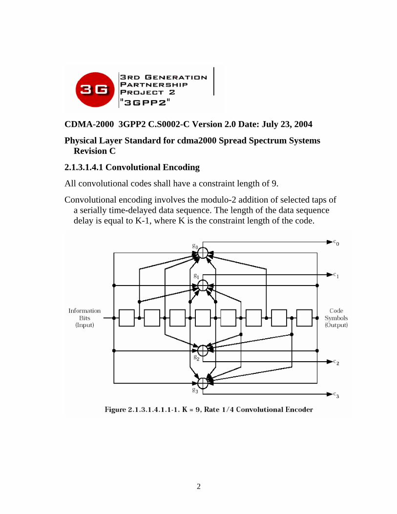
2.1.3.1.4.1 Convolutional Encoding
All convolutional codes shall have a constraint length of 9.
Convolutional encoding involves the modulo-2 addition of selected taps of a serially time-delayed data sequence. The length of the data sequence delay is equal to K-1, where K is the constraint length of the code.
2
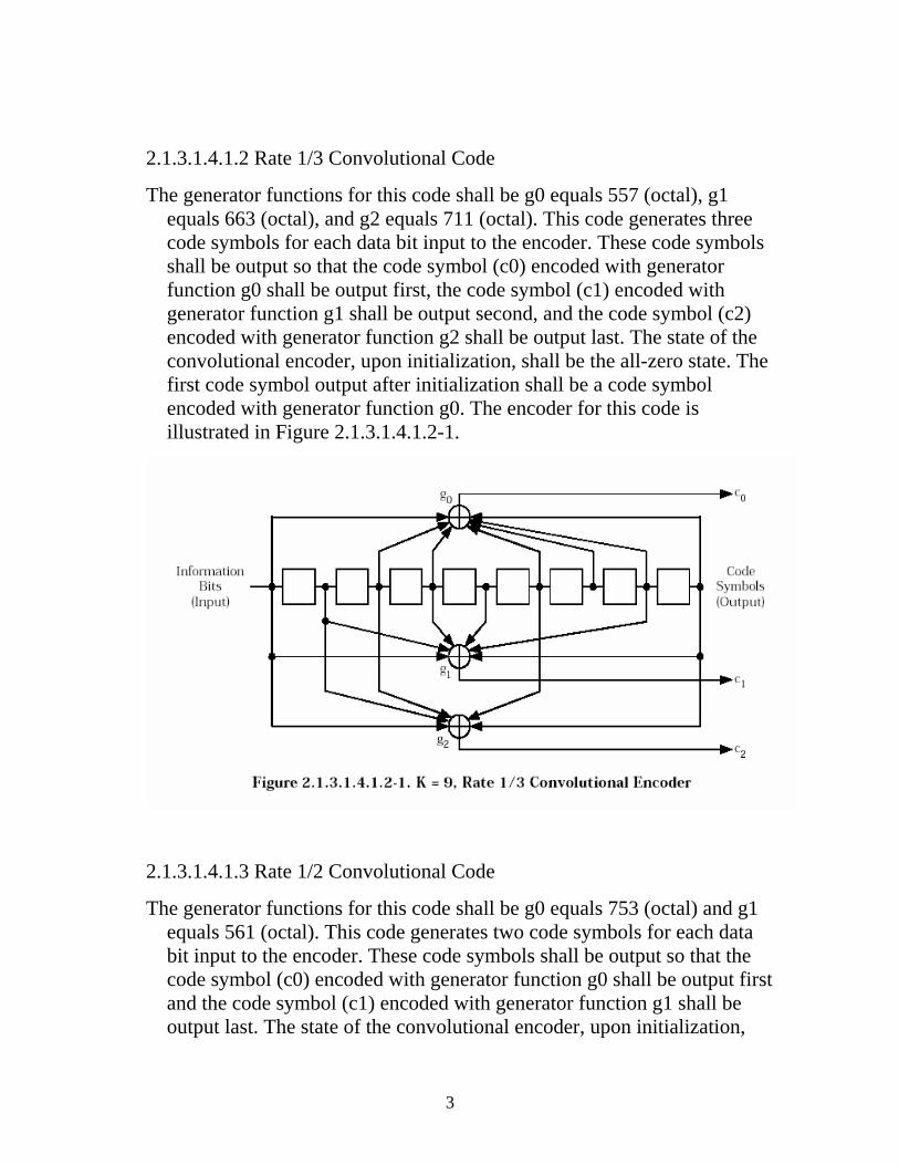
2.1.3.1.4.1.2 Rate 1/3 Convolutional Code
The generator functions for this code shall be g0 equals 557 (octal), g1 equals 663 (octal), and g2 equals 711 (octal). This code generates three code symbols for each data bit input to the encoder. These code symbols shall be output so that the code symbol (c0) encoded with generator function g0 shall be output first, the code symbol (c1) encoded with generator function g1 shall be output second, and the code symbol (c2) encoded with generator function g2 shall be output last. The state of the convolutional encoder, upon initialization, shall be the all-zero state. The first code symbol output after initialization shall be a code symbol encoded with generator function g0. The encoder for this code is illustrated in Figure 2.1.3.1.4.1.2-1.
2.1.3.1.4.1.3 Rate 1/2 Convolutional Code
The generator functions for this code shall be g0 equals 753 (octal) and g1 equals 561 (octal). This code generates two code symbols for each data bit input to the encoder. These code symbols shall be output so that the code symbol (c0) encoded with generator function g0 shall be output first and the code symbol (c1) encoded with generator function g1 shall be output last. The state of the convolutional encoder, upon initialization,
3
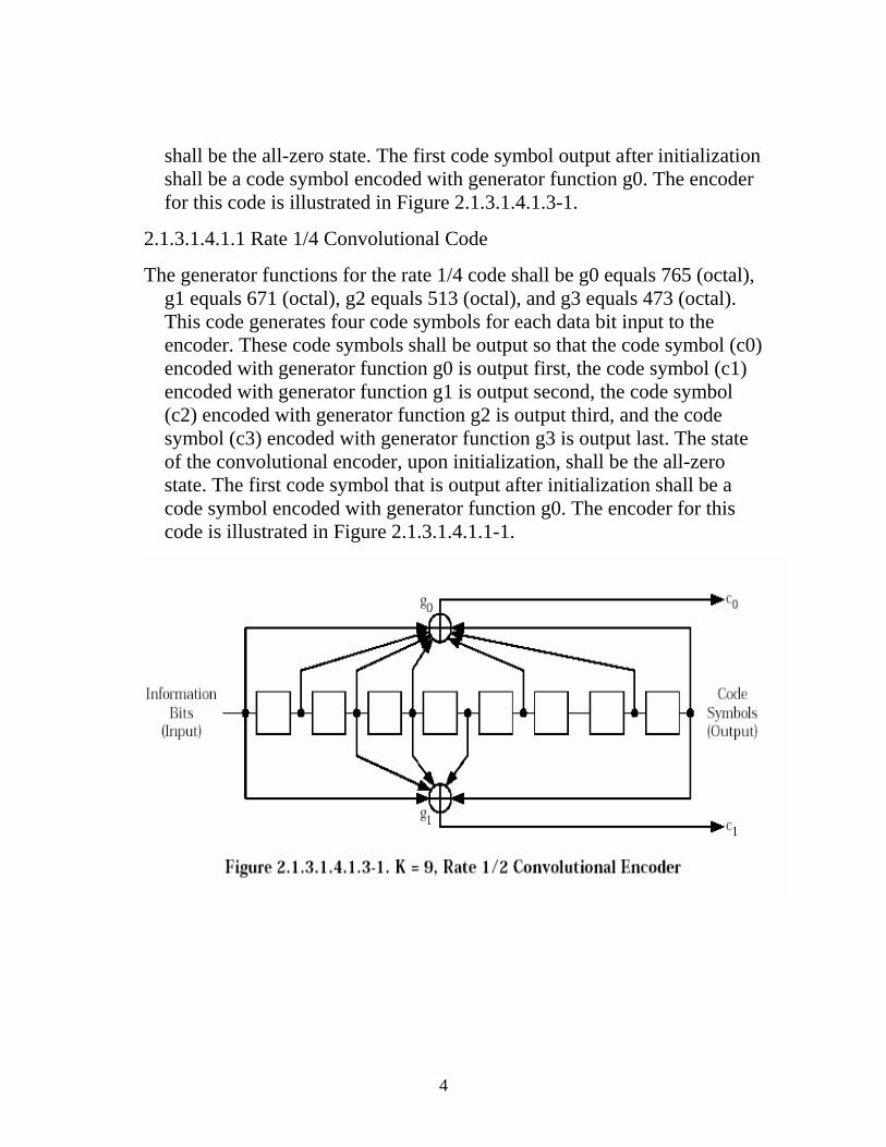
shall be the all-zero state. The first code symbol output after initialization shall be a code symbol encoded with generator function g0. The encoder for this code is illustrated in Figure 2.1.3.1.4.1.3-1.
2.1.3.1.4.1.1 Rate 1/4 Convolutional Code
The generator functions for the rate 1/4 code shall be g0 equals 765 (octal), g1 equals 671 (octal), g2 equals 513 (octal), and g3 equals 473 (octal). This code generates four code symbols for each data bit input to the encoder. These code symbols shall be output so that the code symbol (c0) encoded with generator function g0 is output first, the code symbol (c1) encoded with generator function g1 is output second, the code symbol (c2) encoded with generator function g2 is output third, and the code symbol (c3) encoded with generator function g3 is output last. The state of the convolutional encoder, upon initialization, shall be the all-zero state. The first code symbol that is output after initialization shall be a code symbol encoded with generator function g0. The encoder for this code is illustrated in Figure 2.1.3.1.4.1.1-1.
4
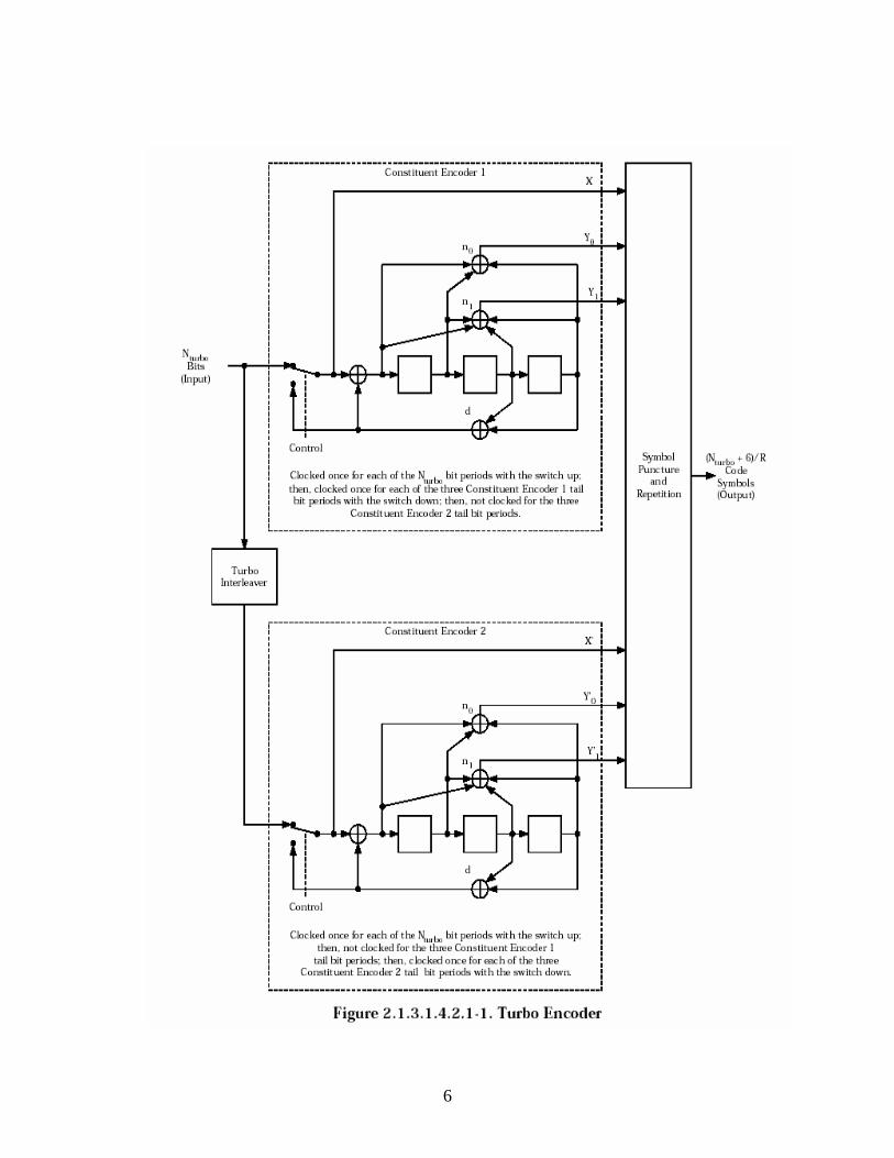
2.1.3.1.4.2 Turbo Encoding The turbo encoder encodes the data, frame quality indicator (CRC), and two
reserved bits. During encoding, an encoder output tail sequence is added. If the total number of data, frame quality, and reserved input bits is N turbo, the turbo encoder generates N turbo/R encoded data output symbols followed by 6/R tail output symbols, where R is the code rate of 1/2, 1/3, 1/4, or 1/5. The turbo encoder employs two systematic, recursive, convolutional encoders connected in parallel, with an interleaver, the turbo interleaver, preceding the second recursive convolutional encoder. The two recursive convolutional codes are called the constituent codes of the turbo code. The outputs of the constituent encoders are punctured and repeated to achieve the (N turbo + 6)/R output symbols.
2.1.3.1.4.2.1 Rate 1/2, 1/3, 1/4, and 1/5 Turbo Encoders
A common constituent code shall be used for the turbo codes of rate 1/2, 1/3, 1/4, and 1/5. The transfer function for the constituent code shall be
where d(D) = 1 + D2 + D3, n0(D) = 1 + D + D3, and n1(D) = 1 + D + D2 +
D3.
The turbo encoder shall generate an output symbol sequence that is identical to the one generated by the encoder shown in Figure 2.1.3.1.4.2.1-1. Initially, the states of the constituent encoder registers in this figure are set to zero. Then, the constituent encoders are clocked with the switches in the positions noted. The encoded data output symbols are generated by clocking the constituent encoders N turbo times with the switches in the up positions and puncturing the outputs as specified in Table 2.1.3.1.4.2.1-1. Within a puncturing pattern, a ‘0’ means that the symbol shall be deleted and a ‘1’ means that a symbol shall be passed. The constituent encoder outputs for each bit period shall be output in the sequence X, Y0, Y1, X , Y 0, Y 1 with the X output first. Symbol repetition is not used in generating the encoded data output symbols. used in generating the encoded data output symbols.
5
6
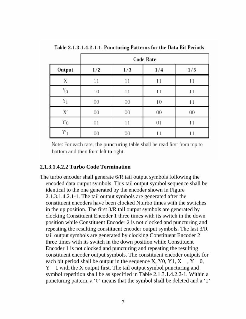
2.1.3.1.4.2.2 Turbo Code Termination
The turbo encoder shall generate 6/R tail output symbols following the encoded data output symbols. This tail output symbol sequence shall be identical to the one generated by the encoder shown in Figure 2.1.3.1.4.2.1-1. The tail output symbols are generated after the constituent encoders have been clocked Nturbo times with the switches in the up position. The first 3/R tail output symbols are generated by clocking Constituent Encoder 1 three times with its switch in the down position while Constituent Encoder 2 is not clocked and puncturing and repeating the resulting constituent encoder output symbols. The last 3/R tail output symbols are generated by clocking Constituent Encoder 2 three times with its switch in the down position while Constituent Encoder 1 is not clocked and puncturing and repeating the resulting constituent encoder output symbols. The constituent encoder outputs for each bit period shall be output in the sequence X, Y0, Y1, X , Y 0, Y 1 with the X output first. The tail output symbol puncturing and symbol repetition shall be as specified in Table 2.1.3.1.4.2.2-1. Within a puncturing pattern, a ‘0’ means that the symbol shall be deleted and a ‘1’
7
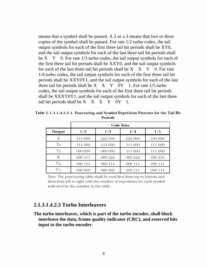
means that a symbol shall be passed. A 2 or a 3 means that two or three copies of the symbol shall be passed. For rate 1/2 turbo codes, the tail output symbols for each of the first three tail bit periods shall be XY0, and the tail output symbols for each of the last three tail bit periods shall be X Y 0. For rate 1/3 turbo codes, the tail output symbols for each of the first three tail bit periods shall be XXY0, and the tail output symbols for each of the last three tail bit periods shall be X X Y 0. For rate 1/4 turbo codes, the tail output symbols for each of the first three tail bit periods shall be XXY0Y1, and the tail output symbols for each of the last three tail bit periods shall be X X Y 0Y 1. For rate 1/5 turbo codes, the tail output symbols for each of the first three tail bit periods shall be XXXY0Y1, and the tail output symbols for each of the last three tail bit periods shall be X X X Y 0Y 1.
2.1.3.1.4.2.3 Turbo Interleavers The turbo interleaver, which is part of the turbo encoder, shall block
interleave the data, frame quality indicator (CRC), and reserved bits input to the turbo encoder.
8
The turbo interleaver shall be functionally equivalent to an approach where the entire sequence of turbo interleaver input bits are written sequentially into an array at a sequence of addresses, and then the entire sequence is read out from a sequence of addresses that are defined by the procedure described below.
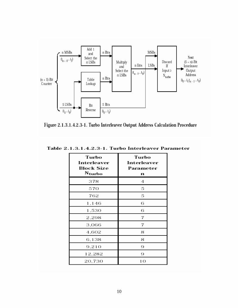
Let the sequence of input addresses be from 0 to Nturbo – 1, where Nturbo is the total number of information bits, frame quality indicator bits, and reserved bits in the turbo interleaver. Then, the sequence of interleaver output addresses shall be equivalent to those generated by the procedure illustrated in Figure 2.1.3.1.4.2.3-1 and described below.16
1. Determine the turbo interleaver parameter, n, where n is the smallest integer such that Nturbo 2n + 5. Table 2.1.3.1.4.2.3 -1 gives this parameter for the numbers of bits per frame that are available without flexible data rates.
2. Initialize an (n + 5)-bit counter to 0.
3. Extract the n most significant bits (MSBs) from the counter and add one to form a new value. Then, discard all except the n least significant bits (LSBs) of this value.
4. Obtain the n-bit output of the table lookup defined in Table 2.1.3.1.4.2.3-2 with a read address equal to the five LSBs of the counter. Note that this table depends on the value of n.
5. Multiply the values obtained in Steps 3 and 4, and discard all except the n LSBs.
6. Bit-reverse the five LSBs of the counter.
7. Form a tentative output address that has its MSBs equal to the value obtained in Step 6 and its LSBs equal to the value obtained in Step 5.
8. Accept the tentative output address as an output address if it is less than Nturbo; otherwise, discard it.
9. Increment the counter and repeat Steps 3 through 8 until all Nturbo interleaver output addresses are obtained.
9
10
W-CDMA 3GPP TS 25.212 V6.3.0 (2004-12) 3rd Generation Partnership Project; Technical Specification
Group Radio Access Network; Multiplexing and channel coding (FDD) (Release 6)
4.2.3 Channel coding
Code blocks are delivered to the channel coding block. They are denoted by , where i is the TrCH number, r is the code block
number, and Ki is the number of bits in each code block. The number of code blocks on TrCH i is denoted by Ci. After encoding the bits are denoted by , where Yi is the number of encoded bits. The relation between oirk and yirk and between Ki and Yi is dependent on the channel coding scheme.
iirKiririr oooo ,,,, 321 K
iirYiririr yyyy ,,,, 321 K
The following channel coding schemes can be applied to TrCHs:
- convolutional coding;
- turbo coding.
Usage of coding scheme and coding rate for the different types of TrCH is shown in table 1.
The values of Yi in connection with each coding scheme:
- convolutional coding with rate 1/2: Yi = 2*Ki + 16; rate 1/3: Yi = 3*Ki + 24;
- turbo coding with rate 1/3: Yi = 3*Ki + 12.
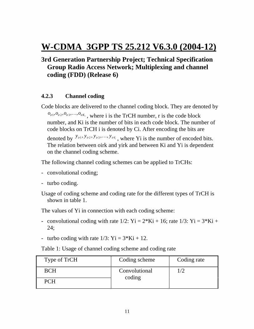
Table 1: Usage of channel coding scheme and coding rate
Type of TrCH Coding scheme Coding rate
BCH
PCH
Convolutional coding
1/2
11
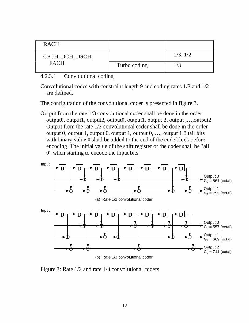
RACH
1/3, 1/2 CPCH, DCH, DSCH, FACH Turbo coding 1/3
4.2.3.1 Convolutional coding
Convolutional codes with constraint length 9 and coding rates 1/3 and 1/2 are defined.
The configuration of the convolutional coder is presented in figure 3.
Output from the rate 1/3 convolutional coder shall be done in the order output0, output1, output2, output0, output1, output 2, output ,…,output2. Output from the rate 1/2 convolutional coder shall be done in the order output 0, output 1, output 0, output 1, output 0, …, output 1.8 tail bits with binary value 0 shall be added to the end of the code block before encoding. The initial value of the shift register of the coder shall be "all 0" when starting to encode the input bits.
Output 0G0 = 557 (octal)
InputD D D D D D D D
Output 1G1 = 663 (octal)
Output 2G2 = 711 (octal)
Output 0G0 = 561 (octal)
InputD D D D D D D D
Output 1G1 = 753 (octal)
(a) Rate 1/2 convolutional coder
(b) Rate 1/3 convolutional coder Figure 3: Rate 1/2 and rate 1/3 convolutional coders
12
4.2.3.2 Turbo coding
4.2.3.2.1 Turbo coder
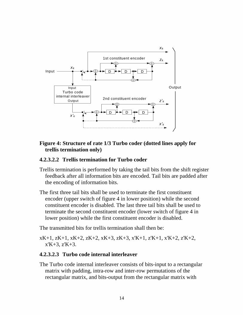
The scheme of Turbo coder is a Parallel Concatenated Convolutional Code (PCCC) with two 8-state constituent encoders and one Turbo code internal interleaver. The coding rate of Turbo coder is 1/3. The structure of Turbo coder is illustrated in figure 4.
The transfer function of the 8-state constituent code for PCCC is:
G(D) = ⎥⎦
⎤⎢⎣
⎡)(
)(,1
0
1
Dg
Dg
,
where
g0(D) = 1 + D2 + D3,
g1(D) = 1 + D + D3.
The initial value of the shift registers of the 8-state constituent encoders shall be all zeros when starting to encode the input bits.
Output from the Turbo coder is
x1, z1, z'1, x2, z2, z'2, …, xK, zK, z'K,
where x1, x2, …, xK are the bits input to the Turbo coder i.e. both first 8-state constituent encoder and Turbo code internal interleaver, and K is the number of bits, and z1, z2, …, zK and z'1, z'2, …, z'K are the bits output from first and second 8-state constituent encoders, respectively.
The bits output from Turbo code internal interleaver are denoted by x'1, x'2, …, x'K, and these bits are to be input to the second 8-state constituent encoder.
13
xk
xk
zk
Turbo codeinternal interleaver
x’k
z’k
D
DDD
DD
Input
OutputInput
Output
x’k
1st constituent encoder
2nd constituent encoder
Figure 4: Structure of rate 1/3 Turbo coder (dotted lines apply for
trellis termination only)
4.2.3.2.2 Trellis termination for Turbo coder
Trellis termination is performed by taking the tail bits from the shift register feedback after all information bits are encoded. Tail bits are padded after the encoding of information bits.
The first three tail bits shall be used to terminate the first constituent encoder (upper switch of figure 4 in lower position) while the second constituent encoder is disabled. The last three tail bits shall be used to terminate the second constituent encoder (lower switch of figure 4 in lower position) while the first constituent encoder is disabled.
The transmitted bits for trellis termination shall then be:
xK+1, zK+1, xK+2, zK+2, xK+3, zK+3, x'K+1, z'K+1, x'K+2, z'K+2, x'K+3, z'K+3.
4.2.3.2.3 Turbo code internal interleaver
The Turbo code internal interleaver consists of bits-input to a rectangular matrix with padding, intra-row and inter-row permutations of the rectangular matrix, and bits-output from the rectangular matrix with
14
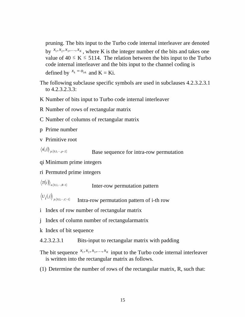
pruning. The bits input to the Turbo code internal interleaver are denoted by , where K is the integer number of the bits and takes one value of 40 K 5114. The relation between the bits input to the Turbo code internal interleaver and the bits input to the channel coding is defined by and K = Ki.
Kxxxx ,,,, 321 K
≤ ≤
irkk ox =
The following subclause specific symbols are used in subclauses 4.2.3.2.3.1 to 4.2.3.2.3.3:
K Number of bits input to Turbo code internal interleaver
R Number of rows of rectangular matrix
C Number of columns of rectangular matrix
p Prime number
v Primitive root
( ) { 2,,1,0 −∈ pjjsL } Base sequence for intra-row permutation
qi Minimum prime integers
ri Permuted prime integers
( ) { 1,,1,0 −∈ RiiT
L } Inter-row permutation pattern
( ){ 1,,1,0 −∈ Cj
jiUL } Intra-row permutation pattern of i-th row
i Index of row number of rectangular matrix
j Index of column number of rectangularmatrix
k Index of bit sequence
4.2.3.2.3.1 Bits-input to rectangular matrix with padding
The bit sequence input to the Turbo code internal interleaver is written into the rectangular matrix as follows.
Kxxxx ,,,, 321 K
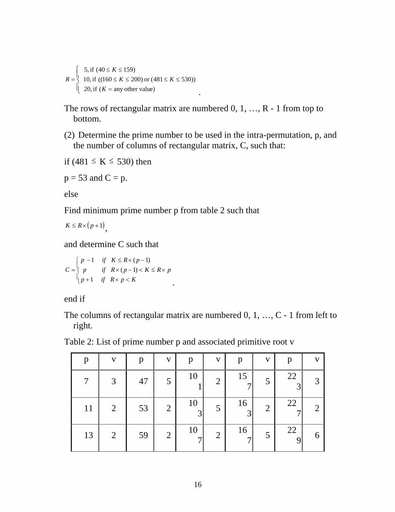
(1) Determine the number of rows of the rectangular matrix, R, such that:
15
⎪⎩
⎪⎨⎧
=≤≤≤≤
≤≤=
e)other valuany ( if 20, ))530481(or )200160(( if 10,
)15940( if 5,
KKK
KR
.
The rows of rectangular matrix are numbered 0, 1, …, R - 1 from top to bottom.
(2) Determine the prime number to be used in the intra-permutation, p, and the number of columns of rectangular matrix, C, such that:
if (481 K 530) then ≤ ≤
p = 53 and C = p.
else
Find minimum prime number p from table 2 such that ( )1+×≤ pRK ,
and determine C such that
⎪⎩
⎪⎨
⎧
<×+×≤<−×
−×≤−=
KpRifppRKpRifp
pRKifpC
1)1(
)1(1
.
end if
The columns of rectangular matrix are numbered 0, 1, …, C - 1 from left to right.
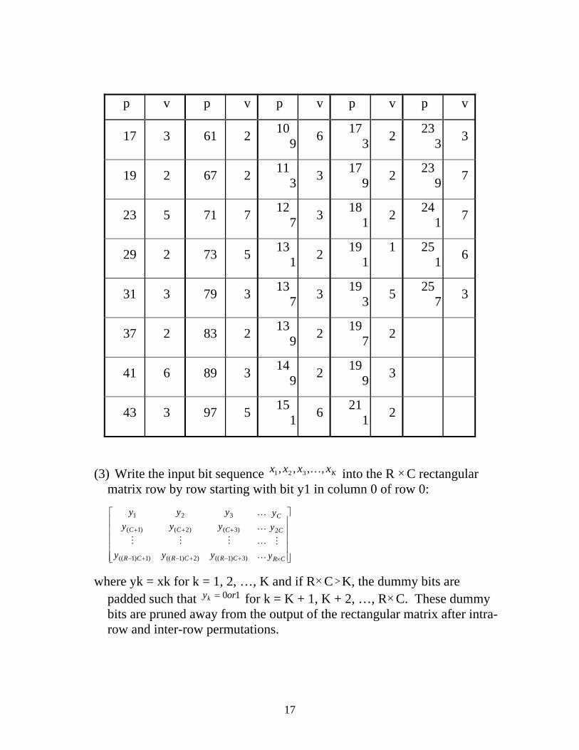
Table 2: List of prime number p and associated primitive root v
p v p v p v p v p v
7 3 47 5 101 2 15
7 5 223 3
11 2 53 2 103 5 16
3 2 227 2
13 2 59 2 107 2 16
7 5 229 6
16
p v p v p v p v p v
17 3 61 2 109 6 17
3 2 233 3
19 2 67 2 113 3 17
9 2 239 7
23 5 71 7 127 3 18
1 2 241 7
29 2 73 5 131 2 19
11 25
1 6
31 3 79 3 137 3 19
3 5 257 3
37 2 83 2 139 2 19
7 2
41 6 89 3 149 2 19
9 3
43 3 97 5 151 6 21
1 2
(3) Write the input bit sequence into the R Kxxxx ,,,, 321 K ×C rectangular matrix row by row starting with bit y1 in column 0 of row 0:
⎥⎥⎥⎥⎥
⎦
⎤
⎢⎢⎢⎢⎢
⎣
⎡
×+−+−+−
+++
CR
C
C
CRCRCR
CCC
y
yy
yyy
yyyyyy
M
K
KMMM
K
K
2
)3)1(()2)1(()1)1((
)3()2()1(
321
where yk = xk for k = 1, 2, …, K and if R×C K, the dummy bits are padded such that for k = K + 1, K + 2, …, R
>10oryk = ×C. These dummy
bits are pruned away from the output of the rectangular matrix after intra-row and inter-row permutations.
17
4.2.3.2.3.2 Intra-row and inter-row permutations
After the bits-input to the R×C rectangular matrix, the intra-row and inter-row permutations for the R×C rectangular matrix are performed stepwise by using the following algorithm with steps (1) – (6):
(1) Select a primitive root v from table 2 in section 4.2.3.2.3.1, which is indicated on the right side of the prime number p.
(2) Construct the base sequence ( ) { 2,,1,0 −∈ pjjsL } for intra-row permutation as:
( ) ( )( ) pjsjs mod1−×= ν , j = 1, 2,…, (p - 2), and s(0) = 1.
(3) Assign q0 = 1 to be the first prime integer in the sequence { }1,,1,0 −∈ RiiqL ,
and determine the prime integer qi in the sequence { 1,,1,0 −∈ RiiqL } to be a
least prime integer such that g.c.d(qi, p - 1) = 1, qi > 6, and qi > q(i - 1) for each i = 1, 2, …, R – 1. Here g.c.d. is greatest common divisor.
(4) Permute the sequence { 1,,1,0 −∈ RiiqL } to make the sequence { 1,,1,0 −∈ Riir L } such
that
rT(i) = qi, i = 0, 1, …, R - 1,
where ( ) { 1,,1,0 −∈ RiiT
L } is the inter-row permutation pattern defined as the one of the four kind of patterns, which are shown in table 3, depending on the number of input bits K.
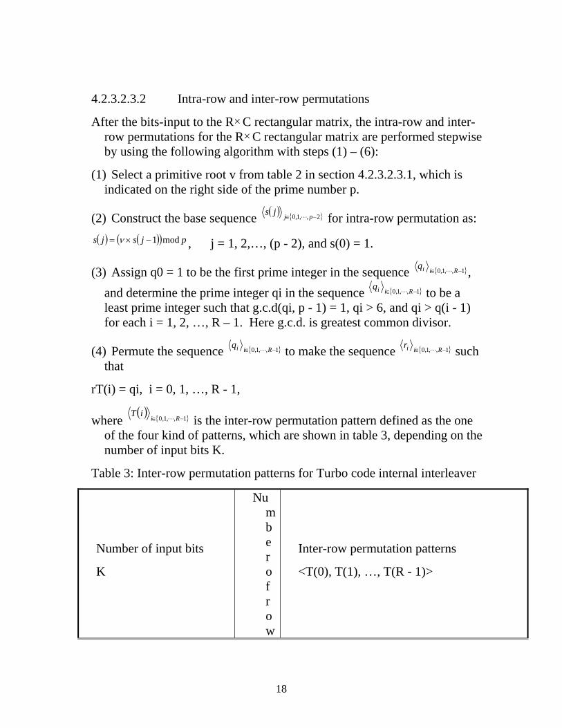
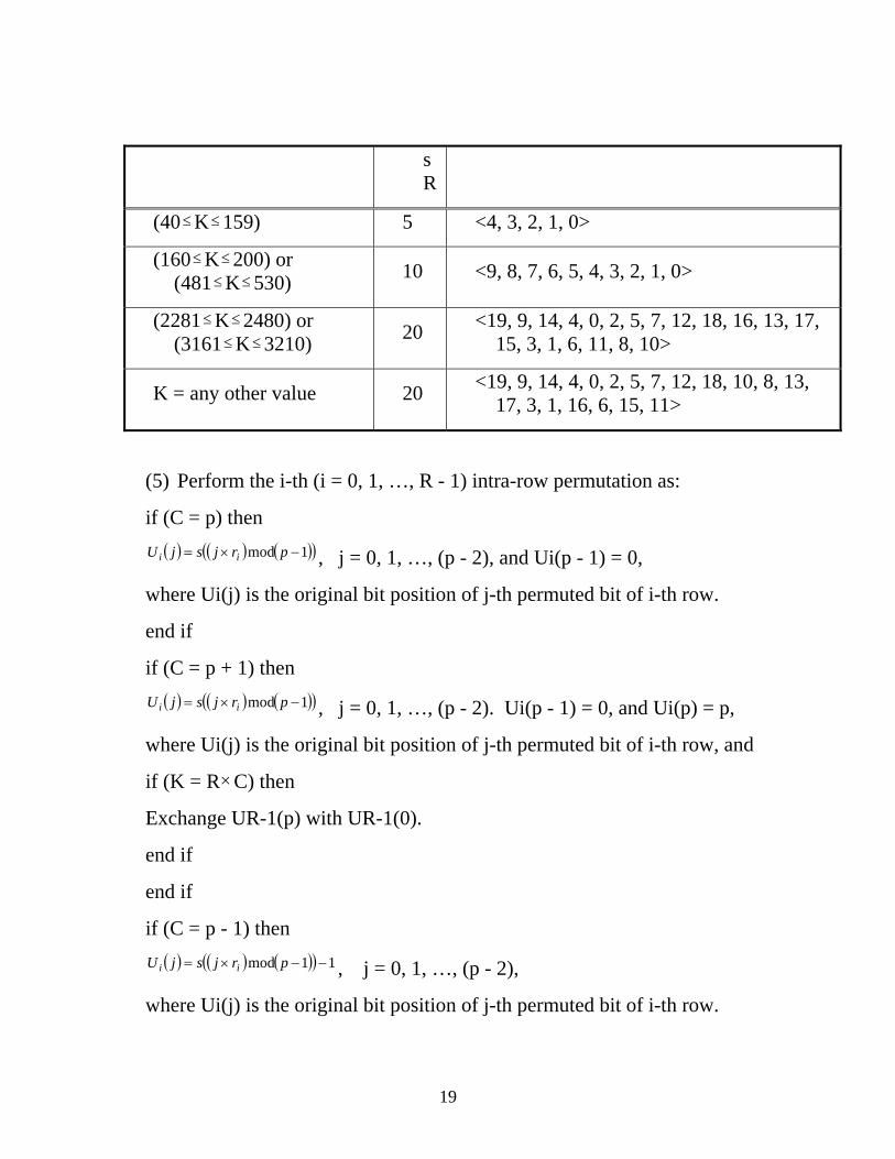
Table 3: Inter-row permutation patterns for Turbo code internal interleaver
Number of input bits
K
Number of row
Inter-row permutation patterns
<T(0), T(1), …, T(R - 1)>
18
s R
(40 K 159) ≤ ≤ 5 <4, 3, 2, 1, 0>
(160 K 200) or (481 K 530)
≤ ≤
≤ ≤ 10 <9, 8, 7, 6, 5, 4, 3, 2, 1, 0>
(2281 K 2480) or (3161 K 3210)
≤ ≤
≤ ≤ 20 <19, 9, 14, 4, 0, 2, 5, 7, 12, 18, 16, 13, 17, 15, 3, 1, 6, 11, 8, 10>
K = any other value 20 <19, 9, 14, 4, 0, 2, 5, 7, 12, 18, 10, 8, 13, 17, 3, 1, 16, 6, 15, 11>
(5) Perform the i-th (i = 0, 1, …, R - 1) intra-row permutation as:
if (C = p) then ( ) ( ) ( )( 1mod −×= prjsjU ii )
)
)
, j = 0, 1, …, (p - 2), and Ui(p - 1) = 0,
where Ui(j) is the original bit position of j-th permuted bit of i-th row.
end if
if (C = p + 1) then ( ) ( ) ( )( 1mod −×= prjsjU ii , j = 0, 1, …, (p - 2). Ui(p - 1) = 0, and Ui(p) = p,
where Ui(j) is the original bit position of j-th permuted bit of i-th row, and
if (K = R×C) then
Exchange UR-1(p) with UR-1(0).
end if
end if
if (C = p - 1) then ( ) ( ) ( )( 11mod −−×= prjsjU ii , j = 0, 1, …, (p - 2),
where Ui(j) is the original bit position of j-th permuted bit of i-th row.
19
end if
(6) Perform the inter-row permutation for the rectangular matrix based on
the pattern ( ) { }1,,1,0 −∈ RiiT
L ,
where T(i) is the original row position of the i-th permuted row.
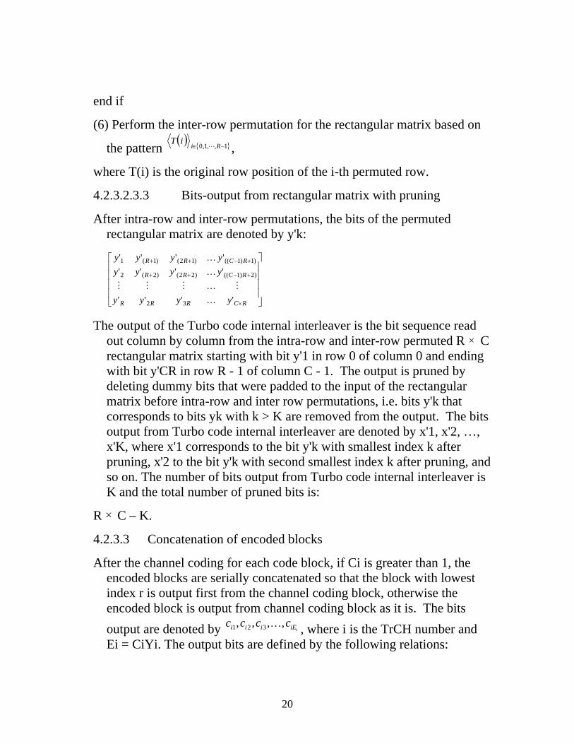
4.2.3.2.3.3 Bits-output from rectangular matrix with pruning
After intra-row and inter-row permutations, the bits of the permuted rectangular matrix are denoted by y'k:
⎥⎥⎥⎥
⎦
⎤
⎢⎢⎢⎢
⎣
⎡
×
+−
+−
++
++
RC
RC
RC
RRR
RR
RR
y
yy
yyy
yyyyyy
'
''
'''
''''''
)2)1((
)1)1((
32
)22()2(2
)12()1(1
M
K
KMMM
K
K
The output of the Turbo code internal interleaver is the bit sequence read out column by column from the intra-row and inter-row permuted R × C rectangular matrix starting with bit y'1 in row 0 of column 0 and ending with bit y'CR in row R - 1 of column C - 1. The output is pruned by deleting dummy bits that were padded to the input of the rectangular matrix before intra-row and inter row permutations, i.e. bits y'k that corresponds to bits yk with k > K are removed from the output. The bits output from Turbo code internal interleaver are denoted by x'1, x'2, …, x'K, where x'1 corresponds to the bit y'k with smallest index k after pruning, x'2 to the bit y'k with second smallest index k after pruning, and so on. The number of bits output from Turbo code internal interleaver is K and the total number of pruned bits is:
R × C – K.
4.2.3.3 Concatenation of encoded blocks
After the channel coding for each code block, if Ci is greater than 1, the encoded blocks are serially concatenated so that the block with lowest index r is output first from the channel coding block, otherwise the encoded block is output from channel coding block as it is. The bits output are denoted by , where i is the TrCH number and Ei = CiYi. The output bits are defined by the following relations:
iiEiii cccc ,,,, 321 K
20
kiik yc 1= k = 1, 2, …, Yi
)(,2, iYkiik yc −= k = Yi + 1, Yi + 2, …, 2Yi
)2(,3, iYkiik yc −= k = 2Yi + 1, 2Yi + 2, …, 3Yi
K
))1((,, iii YCkCiik yc −−= k = (Ci - 1)Yi + 1, (Ci - 1)Yi + 2, …, CiYi
If no code blocks are input to the channel coding (Ci = 0), no bits shall be output from the channel coding, i.e. Ei = 0.
21


![0 3GPP2 Turbo Encoder v2the 3GPP2/CDMA-2000 Turbo Encoder specification [1]. The theory of operation of the Turbo Codes is described in the paper by Berrou, Glavieux, and Thitimajshima](https://img.pdfslide.net/doc/110x75/602d6a3f7d2e717f92752817/0-3gpp2-turbo-encoder-v2-the-3gpp2cdma-2000-turbo-encoder-specification-1-the.jpg)