Embed Size (px)
Citation preview
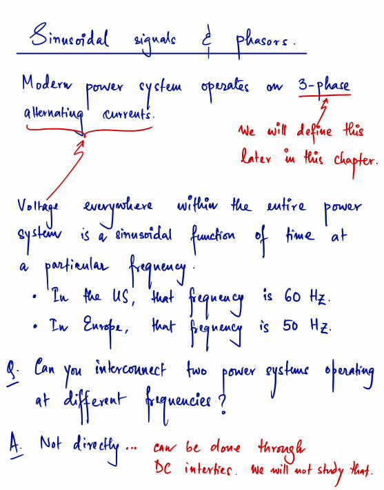
Sinusoidal signals d,
phasors .
Modernpower system operates on
3.ph#alternating currents . J- We will define this
if later in thischapter .
Voltage everywhere within the entirepower
system is a sinusoidal function of time at
a particular frequency .
° In the US,
that frequencyis 60 Hz .
• InEurope ,
thatfrequency
is 50 Hz .
Q . Canyou
interconnect twopower systems operating
-
at different frequencies ?As
Not directly ... caw be done throughDC interties
.
we will not study that .
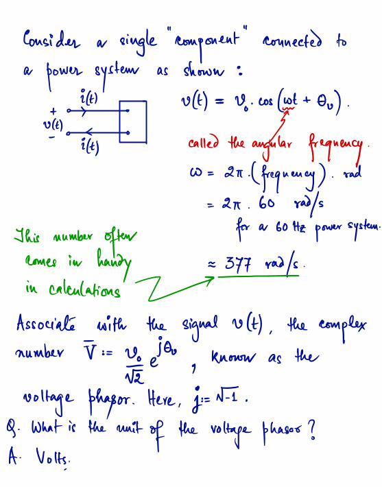
Consider a single"
component
"
connected to
a power system as shown :
ittt utt ) ⇒
v.wstettou) .
+ > o
ya < Y'
it , called the angular frequency .
w= 2 't .(frequency ) .
rad
=
2A.
60 rays
This number oftenfor a 60 Hz power system .
comes in handy = 377 roof .
in calculations /-
Associate with the signal uttt,
the complexnumber =V÷
Uofgetou,
known as the
voltage phagor .Here
, Igoe .
Q . What is the unit of the voltage phases ?
A . Volts.
.
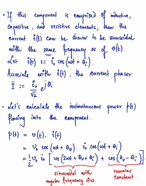
• If thiscomponent
is comprised of inductive,
capacitive ,and resistive elements
,then the
current Eta caw be shown to be sinusoidal
with the safe frequency as of HH.
Let it ) := ious (wt + oi ) .
Associate with ittl ,the current phasor
I := Eoqejoi
• Let's calculate the instantaneouspower ptt)
flowinginto the
component.
put = uttl . itt )
= Vows ( wt + au ) .
io cosfottoi )=
!uoio [ wstwttoutoi ) + cos the - aid .
2- -
sinusoidal with remains
angular frequency 2W .
constant .

•
Average poweris
given by{ play = ¥Tptt ) dt
,
It 4where T is a cycle given byT =
ffefnenqt = £÷ '
asinusoidal with
Recall ptt) has two components ( and ' t9 .2W*
time .invariant
component.
Aug. of
sinusoidalcomponent
= 0
...convince
yourself !
⇒ ( play = I, f.
Tuoio cos Cou - oi ) dt
= ! voio cos too - oi ) .
2
Now,
lets'
express( play in terms
of the phaeors J,
I.

~
* denotes complexNotice that Re{TE* } conjugate .
= re { Enda . ioaetoi }= tzuoio Re { eicoo - oil }
= lzuoio cos Cou - oi ) .
= < pay9n words
,the
average power equalsthereal
part of a complex number 5 = JI*
.
we call 5,
"
complex power"
or
"
apparent power .
"
Q . Is 5 a fhasor ?
A . No ! 5 is not associated with a purelysinusoidal signal that is
physically meaningful .
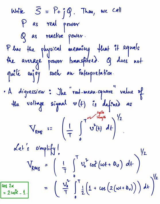
write 5 = Ptjcf .
Then,
we call
P as realpower
Q as reactivepower
.
�1� has the physical meaning that it equalsthe
average powertransferred . Q does not
quite enjoysuch an interpretation
.
i i 11
° A digression : The root -mean .
squarevalue of
the voltage signal ult ) is defined as
are .
Trms := (¥ fTutti dt)"
.
Let's simplify ! 1K
Vrms = ( k,
ftuiwifwttou) dt )1/2
cos 2x
=2wsk.
1 .
= ( ¥ fttz(1+ cos (2( wttou )) ) dt )

sinusoidal with
avg.tn# 42
tons = ( ttf 's@+wsflwttou )) ) dt )r T YZ
= ( ÷fEdt )= V÷
Recall that TT = Y÷eI0u ,which also
aequals Yrmsei
.
° Back tocomplex power
5 = Ptjg .
What are their units 7
• S : volt .
ampere°C VA ) .
• P : wait ( W) .
• Q : volt .
ampere. reactive ( AR ) .
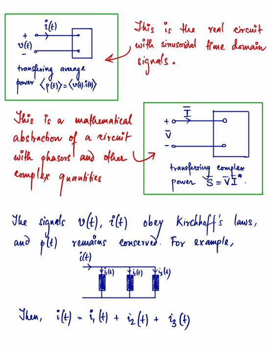
ittt This is the real circuit+ >
ya with sinusoidal
transferring average
4signals .
time domain
power (ftp.hutttittp
TIThis is a mathematical + >
Tabstractionof
a circuit.
withphasors
and other Utransferring complex
complex quantities power
5=TI*.
The signals uttlritt ) obey Kirchhoff 's laws,
and ptt ) remains conserved . For example ,
EHvi.H vidt )viztt )
Ba Ba Ba
Then, ittl = ii TH + izttl + iztt)

The mathematical abstraction with phasorsalso satisfy analogous rules .
I
iggat'iBa¥Zq⇒ Then,
I = I ,+ Is + Is .
Similarly ,← fit ⇒ p.tt) + tzttltpstt )=otsttttpdtl
Equivalently, t¥fg5 ⇒ § + E +53=0
The mathematical abstraction reduces manipulationwith sinusoids to arithmetic on complex numbers .
It is a useful formalism .

Analog of0hm 's law :
* Who ⇒ v. Let - uztt ) = R . it )Uk ) R Uzlt)
g.Ethan; ⇒ F- I = E. I.
E is called the impedance .
E = R if it is a purelyresistive element
.
E =jwL , if it is a purely inductive element .
E- Yjwc) , if it is a purely capacitive element .
• Power triangle : Draw P, 9,5 on the
complex plane .
j
7^9go>
P
cos a is called"
power factor !
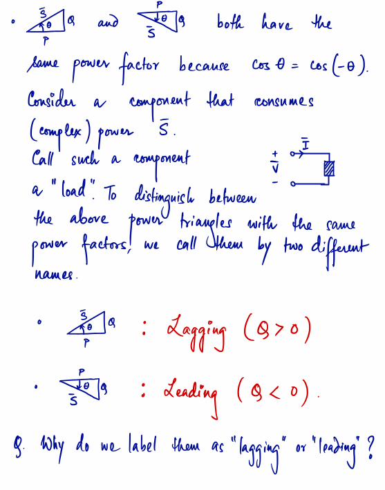
° ftp.aand#g¥9 both have the
Same power factor because cost = Costo ) .
Consider a component that consumes
( complex ) power5
.
±¥Call such acomponent ✓
a"
load"
.
Todistinguish between
-
the abovepower triangles with the same
power factors ,we call them by two different
names .
° Fta : Lagging ( Q > o )
. Testes : Leading ( 9<0 ) .
g. Why do we label them as"
lagging"
or"
leading"
?
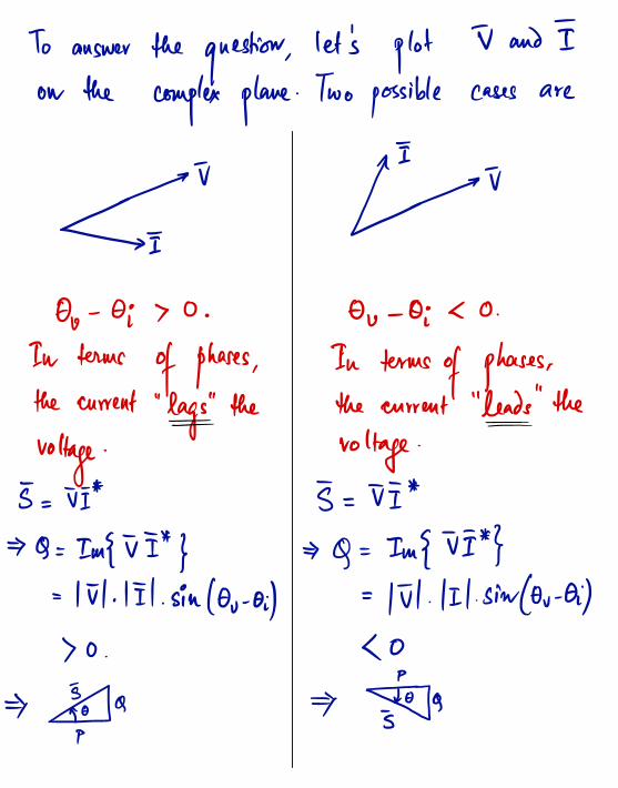
To answer the question,let's plot T and I
on the complex plane. Two possible cases are
t.IT#aOo - Oi > 0
. Ou - Oi < 0.
In termsof phases ,
In terms of phases ,
the current "
lags"
the the current" leads
"
the= =
voltage. voltage .
5=TI* 5=TI*
⇒ Q=Im{TI* } ⇒ Q=Tm{TI* }= III. III. sin (au . oil = III. III. sinfou - Oil
> o.
< o
⇒ f# a ⇒ Esta

![Phasors Final Ron Alexander.ppt [Read-Only] · While represented as phasors, the impedance and power “phasors” do not rotate at system frequency. The international standard is](https://img.pdfslide.net/doc/110x75/5e187b822001895a3240f732/phasors-final-ron-read-only-while-represented-as-phasors-the-impedance-and-power.jpg)