Embed Size (px)
Citation preview

4 Arrayed Waveguide Gratings
Xaveer J. M. Leijtens, Berndt Kuhlow and Meint K. Smit
4.1 Introduction
Arrayed Waveguide Grating (AWG) multiplexers/demultiplexers are pla-nar devices which are based on an array of waveguides with both imaging and dispersive properties. They image the field in an input waveguide onto an array of output waveguides in such a way that the different wavelength signals present in the input waveguide are imaged onto different output waveguides. AWGs were first reported by Smit [1] (1988) and later by Takahashi [2] (1990) and Dragone [3] (1991). They are known under dif-ferent names: Phased Arrays (PHASARs), Arrayed Waveguide Gratings (AWGs), and Waveguide Grating Routers (WGRs). The acronym AWG, introduced by Takahashi [2], is the most frequently used name today and will also be used in this text. Together with Thin-Film Filters and Fibre Bragg Gratings, AWGs are the most important filter type applied in WDM networks, and with the advance of Photonic Integrated Circuits technology they are expected to become the most important one. Their operation prin-ciples will be described in Sect. 4.2.
The most important technologies used for realisation of AWGs today are silica-on-silicon technology and Indiumphosphide (InP)-based semi-conductor technology. In addition, research on silicon-based polymer tech-nology [4, 5] and on lithium niobate [6] have been reported as well.
Silica-on-silicon (SoS) AWGs have been introduced to the market in 1994 and currently hold the largest share of the AWG market. Their modal field matches well with that of a fibre, and therefore it is relatively easy to couple them to fibres. They combine low propagation loss (< 0.05 dB/cm) with a high fibre-coupling efficiency (losses in the order of 0.1 dB). A disadvantage is that they are relatively large due to their fibre matched waveguide properties, which prohibit the use of short bends. This is pres-ently being improved by using higher index contrast and spot-size convert-ers to keep fibre coupling losses low. SoS-based AWGs will be described in detail in Sect. 4.3.

126 4 Arrayed Waveguide Gratings
AWGs can be utilized to accomplish complex functionalities in fibre op-tic WDM networks. They are also increasingly used in other areas such as signal processing, measurement, and characterisation or sensing as well. Integration of AWGs enables compact, high functionality devices. Exam-ples from the area of fibre optic communication will be presented in Sect. 4.4.
Semiconductor-based devices have the potential to integrate a wide va-riety of functions on a single chip; they are suitable for integration of pas-sive devices such as AWGs with active ones such as electro-optical switches, modulators, and optical amplifiers, and also non-linear devices such as wavelength converters. The dominant technology for operation in the telecom window is based on InP. InP-based AWGs can be very com-pact due to the large index-contrast of InP-based waveguides. The market for integrated components is still small, but it is expected to become in-creasingly important in the coming years. InP-based technology will be described in Sect. 4.5, a brief description of other material systems is given in Sect. 4.6, and finally, characterisation of AWGs is discussed in Sect. 4.7.
4.2 Operation Principle and Device Characteristics
4.2.1 Principle
Figure 4.1 shows the schematic layout of an AWG-demultiplexer, and the operation can be understood as follows [7]. When a beam propagating through the transmitter waveguide enters the first Free Propagation Region (FPR) it is no longer laterally confined and becomes divergent. On arriving at the input aperture the beam is coupled into the waveguide array and propagates through the individual waveguides towards the output aperture. The length of the array waveguides is chosen such that the optical path length difference between adjacent waveguides equals an integer multiple of the central wavelength c of the demultiplexer. For c , the fields in the individual waveguides arrive at the output aperture with equal phase (mod. 2 ), and thus the field distribution at the input aperture is reproduced at the output aperture. The divergent beam at the input aperture is thus trans-formed into a convergent one with equal amplitude and phase distribution, and the input field at the object plane gives rise to a corresponding image at the centre of the image plane. The spatial separation of different wave-lengths is obtained by linearly increasing the lengths of the array wave-guides, which introduces a wavelength-dependent tilt of the outgoing beam

4.2 Operation Principle and Device Characteristics 127
associated with a shift of the focal point along the image plane. If receiver waveguides are placed at proper positions along the image plane, different wavelengths are led to different output ports.
4.2.2 Focusing, Spatial Dispersion, and Free Spectral Range
Focusing of the fields propagating in an AWG is obtained if the length difference L between adjacent waveguides is equal to an integer number m of wavelengths inside the AWG:
eff
c
nmL (4.1)
Fig. 4.1. (a) Geometry of an AWG demultiplexer, (b) beam focusing geometry in the free propagation region

128 4 Arrayed Waveguide Gratings
The integer m is called the order of the array, c is the central wave-length (in vacuo) of the AWG, effn is the effective refractive (phase) index of the guided mode, and effc / n corresponds to the wavelength inside the array waveguides. Under these circumstances the array behaves like a lens with image and object planes at a distance aR of the array apertures. On the other hand, the focal line (which defines the image plain) follows a circle with radius 2/aR , and transmitter and receiver waveguides should be located on this line. This geometry is equivalent to a Rowland-type mounting.
The length increment L of the array gives rise to a phase difference ac-cording to
L (4.2)
where
cn /2 eff (4.3)
is the propagation constant in the waveguides, = c/ is the frequency of the propagating wave, and c is the speed of light in vacuo. The wave-length-dependent phase difference introduces the wavelength-depen-dent tilt of the outgoing wave front associated with a wavelength-de-pendent shift of the corresponding image (as already mentioned above). The lateral displacement ds of the focal spot along the image plane per unit frequency change d is called the spatial dispersion spD of the AWG, which is given by (for details see [8]):
L
n
nsD
FPR
g
csp
1dd
(4.4)
where FPRn is the (slab) mode index in the Free Propagation Region, is the divergence angle between the array waveguides in the fan-in and the fan-out sections, and gn is the group index of the waveguide mode:
d
d effeffg
nnn (4.5)
According to (4.1) and (4.4) the (spatial) dispersion is fully determined by the order m and the divergence angle , and as a consequence filling-in of the space between the array waveguides near the apertures due to finite lithographical resolution (cf. Sects. 4.3 and 4.4) does not affect the dispersive properties of the AWG.
If the input wavelength change is such that the phase difference be-tween adjacent waveguides (4.2) has increased by 2 , the transfer will be

4.2 Operation Principle and Device Characteristics 129
the same as before, i. e. the response of the AWG is periodic. The period in the frequency domain is called the Free Spectral Range (FSR), and
L in combination with (4.1) leads to:
g
eff
n
n
mcFSR (4.6)
In order to avoid crosstalk problems with adjacent orders, the free spec-tral range should be larger than the whole frequency range spanned by all channels, and thus for a demultiplexer with 8 channels and 200 GHz chan-nel spacing for example, the FSR should be at least 1600 GHz. If the chan-nels are centred around 1550 nm, (4.6) yields that this requires an array with an order of about 120 (with neff / ng 0.975 for the SoS- and neff / ng 0.9 for the InP-material system).
If the device is to be used in combination with Erbium-Doped Fibre Amplifiers (EDFAs), the FSR should be chosen such that adjacent orders do not coincide with the peak of the EDFA gain spectrum in order to avoid accumulation of Amplified Spontaneous Emission (ASE).
4.2.3 Insertion Loss and Non-uniformity
Fields propagating through an AWG are attenuated due to various loss mechanisms. The most important contribution to this loss is coming from the junctions between the free propagation regions and the waveguide ar-ray. For low-loss the fan-in and fan-out sections should operate adiabati-cally, i. e. there should be a smooth transition from the guided propagation in the array to the free-space propagation in the FPRs and vice versa. This will occur if the divergence angle between the array waveguides is sufficiently small and the vertex between the waveguides is sufficiently sharp. Due to the finite resolution of the lithographical process blunting of the vertex will occur. Junction losses for practical devices are between 1 and 2 dB per junction (i. e. between 2–4 dB for the total device). Propa-gation loss in the AWG and coupling losses due to a mismatch between the imaged field and the receiver waveguide mode (see below) are usually much smaller.
If the transmission for the central channel of the AWG is Tc, then the at-tenuation of the central channel is given by
c0 log10 TA (4.7)
From Fig. 4.2a it is seen that the outer channels have more loss than the central ones. This reduction is caused by the fact that the far field of the

130 4 Arrayed Waveguide Gratings
individual array waveguides drops in directions different from the main optical axis. The envelope, as indicated in the figure, is mainly determined by the far field radiation pattern of the individual array waveguides. The non-uniformity AWGT is defined as the difference in transmission bet-ween the central channel(s) and the outermost channels (nrs. 1 and N):
c
,1AWG log10
T
TT N (4.8)
in which Tc is the transmission of the central channel(s). The power which is lost from the main lobe will appear in adjacent or-
ders, as shown in the left part of Fig. 4.2. If the free spectral range is cho-sen N times the channel spacing, then the outer channels of the AWG will experience almost 3 dB more loss than the central channels, i. e. the non-uniformity is close to 3 dB. This is because at a deflection angle at half the angular distance between the orders of the array the power in the image is reduced by 50% because at that angle it will be equally divided over the two orders at both sides of the optical axis. In a periodical AWG the outer channels will be close to these 3–dB points.
From the above it is clear that the non-uniformity of an AWG can be reduced by increasing the FSR, however, at the expense of a larger device-size.
Fig. 4.2. (Left) The field in the image plane for different wavelengths, showing the influence of the far-field pattern of the individual array waveguide and the occurrence of different orders (Right) the corresponding frequency response curve for the different channels

4.2 Operation Principle and Device Characteristics 131
4.2.4 Bandwidth
As explained in the introduction, AWGs are lens-like imaging devices; they form an image of the field in the object plane at the image plane. Be-cause of the linear length increment of the array waveguides the lens ex-hibits dispersion: if the wavelength changes, the image moves along the image plane without changing shape, in principle. Most of the AWG prop-erties can be understood by considering the coupling behaviour of the focal field in the image plane to the receiver waveguide(s). This coupling is de-scribed by the overlap integral of the normalised receiver waveguide mode Ur (s) and the normalised focal field Uf (s) in the image plane, as illustrated in Fig. 4.3:
2
)()()( dssUssUs rf (4.9)
in which s is the displacement of the focal field relative to the receiver waveguide centre. If Ur (s) and the image field Uf (s) have the same shape, which will be the case if identical waveguides are used for the transmitter and receiver waveguides, then the coupling efficiency can be close to 100% on proper design of the AWG. The power transfer function )(iTfor the i-th receiver waveguide is found by substituting
)(sp iDs (4.10)
in (4.9), which yields
)}({)( spc ii DTT (4.11)
Fig. 4.3. The receiver waveguide mode profile Ur (s) and the focal field Uf (s)
132 4 Arrayed Waveguide Gratings
where i is the frequency corresponding to the i-th channel. The power transmission of the (virtual) central channel Tc is normally smaller than 1 due to the transmission losses in the AWG, and it is also worthwhile to note that for an even number of channels there will be no receiver wa-veguide at the centre of the image plane. Figure 4.2 shows an example of a demultiplexer response curve for different channels, in which the most important characteristics of the device are indicated.
To analyse the transmission loss at the input and output aperture of the array, which form the main contributions to the total insertion loss for the central channels of the device, the most usual approach is to overlap (4.9) the far field of the transmitter with the sum field of the individual array waveguides, with excitation coefficients proportional to the incident field strength. This analysis ignores the coupling between the waveguides, which will reduce the transition losses at the input and output aperture of the arrays. A more rigorous analysis of the array imaging properties is presented in [9].
4.2.5 Passband Shape
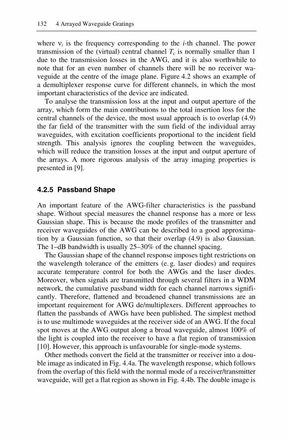
An important feature of the AWG-filter characteristics is the passband shape. Without special measures the channel response has a more or less Gaussian shape. This is because the mode profiles of the transmitter and receiver waveguides of the AWG can be described to a good approxima-tion by a Gaussian function, so that their overlap (4.9) is also Gaussian. The 1–dB bandwidth is usually 25–30% of the channel spacing.
The Gaussian shape of the channel response imposes tight restrictions on the wavelength tolerance of the emitters (e. g. laser diodes) and requires accurate temperature control for both the AWGs and the laser diodes. Moreover, when signals are transmitted through several filters in a WDM network, the cumulative passband width for each channel narrows signifi-cantly. Therefore, flattened and broadened channel transmissions are an important requirement for AWG de/multiplexers. Different approaches to flatten the passbands of AWGs have been published. The simplest method is to use multimode waveguides at the receiver side of an AWG. If the focal spot moves at the AWG output along a broad waveguide, almost 100% of the light is coupled into the receiver to have a flat region of transmission [10]. However, this approach is unfavourable for single-mode systems.
Other methods convert the field at the transmitter or receiver into a dou-ble image as indicated in Fig. 4.4a. The wavelength response, which follows from the overlap of this field with the normal mode of a receiver/transmitter waveguide, will get a flat region as shown in Fig. 4.4b. The double image is

4.2 Operation Principle and Device Characteristics 133
created by use of a short MMI coupler [11], a Y-junction [12] or a non-adiabatic parabolic horn [13], where the best results are achieved with the parabolic horn. Other approaches based on spatial filtering use waveguide arm length changes inside the AWG that excite a sinc-like field distribution at the grating exit, which produces, via Fourier transform, a rectangular transmission shape [14, 15]. The use of interleaved gratings [16] or phase-dithering [17] for this purpose have also been published.
All these techniques fundamentally increase the insertion loss (on the order of 3 dB) because only a portion of the image is focused onto each waveguide output. This can be avoided by combining the AWG with a synchronized AWG or MZI-duplexer at the input, as is demonstrated, for example, in [18, 19]. A discussion of different techniques for passband flattening with a list of references is given in [15].
4.2.6 Crosstalk
One of the most important characteristics of the device is the inter-channel crosstalk. It is the contribution of unwanted signals, e. g. in the case of adja-cent channels, the contribution of the (unwanted) signal at frequency i+1 to the (detected) channel i. The theoretical adjacent-channel crosstalk Ax fol-lows from the overlap of the focal field with the unwanted mode (4.9) as
)(dAx (4.12)
with d being the distance between adjacent receiver waveguides. From this formula it is seen that arbitrary large crosstalk attenuation is possible by positioning the receiver waveguides sufficiently far apart. Usually a gap of
(a) (b)
Fig. 4.4. Wavelength response flattening: (a) Shape of the focal field Uf required forobtaining a flat region in the overlap with the receiver mode Ur, (b) wavelength re-sponse obtained by applying a camel-shaped focal field (the dashed curve indicates the non-flattened response obtained by applying a non-modified focal field, i. e. Uf = Ur

134 4 Arrayed Waveguide Gratings
1–2 times the waveguide width is sufficient for more than 40 dB adjacent inter-channel crosstalk attenuation. However, in practice other mechanisms appear to limit the crosstalk attenuation. The most important ones are er-rors in the phase transfer of the array waveguides. They are due to non-uniformities in layer thickness, waveguide width, and refractive index and cause a rather noisy “crosstalk floor”, which is better than 35 dB for good devices. Semiconductor-based devices exhibit slightly inferior crosstalk figures compared to silica-based ones.
Crosstalk figures provided for experimental and commercial devices usually refer to single-channel crosstalk levels, i. e. the crosstalk resulting from a single channel. In an operational environment crosstalk contribu-tions from all active channels will impair the crosstalk level compared to the single-channel crosstalk attenuation. This effect is discussed in [20] (Note: One should keep in mind that crosstalk is defined in such a way (cf. Glossary) that device behaviour is the better the higher the crosstalk which is somewhat counter-intuitive).
4.2.7 Wavelength Routing Properties
An interesting device is obtained if the AWG is designed with N input and N output waveguides and a free spectral range equalling N times the chan-nel spacing. With such an arrangement the device behaves cyclical: a sig-nal disappearing from output N will reappear at output 1, if the frequency is increased by an amount equal to the channel spacing. Such a device is called a cyclical wavelength router [3]. It provides an important additional functionality compared to multiplexers and demultiplexers and plays a key role in more complex devices as add-drop multiplexers and wavelength switches. Figure 4.5 illustrates its functionality. Each of the N input ports can carry N different frequencies. The N frequencies carried by input channel 1 (signals a1–a4 in Fig. 4.5) are distributed among output channels
a1, a2, a3, a4
b1, b2, b3, b4
c1, c2, c3, c4
d1, d2, d3, d4
a4, b3, c2, d1
a3, b2, c1, d4
a2, b1, c4, d3
a1, b4, c3, d2
wavelengthrouter
Fig. 4.5. Schematic diagram illustrating the operation of a wavelength router

4.2 Operation Principle and Device Characteristics 135
1 to N in such a way that output channel 1 carries frequency N (signal a4)and channel N frequency 1 (signal a1). The N frequencies carried by input 2 (signals b1–b4) are distributed in the same way, but cyclically shifted by 1 channel in such a way that frequencies 1–3 are coupled to ports 3–1 and frequency 4 to port 4. In this way each output channel receives N different frequencies, one from each input channel. To realise such an interconnec-tivity scheme in a strictly non-blocking way using a single frequency, a large number of switches would be required. With a wavelength router, this functionality can be achieved using only a single component. Wave-length routers are key components also in multi-wavelength add-drop mul-tiplexers and crossconnects (see below).
4.2.8 Configuration-dependent Crosstalk in Add-drop Multiplexers
One key application of AWGs is adding or dropping wavelengths from a multiplex. AWGs in different configurations can be used for this purpose, and the corresponding interchannel crosstalk is a parameter of particular importance. One standard configuration consists of two symmetrically con-nected 1 N AWGs with identical wavelength response (Fig. 4.6a). This architecture exhibits an almost perfect isolation between the add and the drop port, and spurious intensity of the dropped signal propagating towards the output is suppressed again by the multiplexer, so that the total crosstalk attenuation is essentially doubled. The latter is not the case for cheaper configuration illustrated in Fig. 4.6b which uses a power combiner instead of a multiplexing AWG.
An add-drop multiplexer as shown in Fig. 4.6a can be made configur-able, i. e. the added and dropped wavelengths can be selected with an ex-ternal control signal by combining the (de)multiplexers with switches as
Fig. 4.6. Add-drop multiplexers with fixed add-drop channel. DMX: demultiplexer, MUX: multiplexer

136 4 Arrayed Waveguide Gratings
shown in Fig. 4.7. In the configuration of Fig. 4.7a the add-signal may end up in the drop-port at an undesirably high level through-crosstalk in the switch. In the configuration of Fig. 4.7b, which requires two 1 2 switches per channel instead of one 2 2, the isolation is almost perfect.
A disadvantage of the configurations shown in Fig. 4.6 and Fig. 4.7 is that for low insertion loss operation they require two (de)multiplexers. Fig-ure 4.8 shows an add-drop multiplexer realised with a single (N + 1) (N + 1) AWG. In the first pass through the AWG the four wavelengths are demultiplexed. They are fed to four different switches with which they can
Fig. 4.7. Two reconfigurable add-drop multiplexers, based on one 2x2 switch (a) and two 1x2 switches (b) per channel. DMX: demultiplexer, MUX: multiplexer
in out
add
X
X
X
X
DMXMUX
drop
wavelength router
(a)
DMX
add
drop
in
outXXXX
wavelength router
(b)
MUX
Fig. 4.8. Two add-drop multiplexer configurations based on a single wavelength router in a loop-back configuration (a) and in a fold-back configuration (b). MUX: multi-plexer, DMX: demultiplexer

4.2 Operation Principle and Device Characteristics 137
be switched to the drop port or be looped back to the wavelength router which multiplexes them to the output port. In the drop state a signal applied to the add port will be multiplexed to the output port. A disadvantage of this loop-back configuration is that crosstalk of the AWG is coupled directly into the main output port, where it competes with the transmitted signal, which is attenuated in the loop. This problem can be reduced by applying the AWG in a fold-back configuration as shown in Fig. 4.8b, which requires a larger AWG, however. One advantage of configurations using one AWG only is that the channel wavelengths automatically fit. A comparison of crosstalk properties of different configurations is given in [21].
4.2.9 Polarisation Dependence
If the propagation constants for the fundamental TE- and TM-modes (electrical field vector parallel and perpendicular to the wafer plane, re-spectively), of the array waveguides are equal, the AWG exhibits polari-sation independence, i. e. identical spectral response for any polarisation. On the other hand, any waveguide birefringence, i. e. any difference in propagation constants for TE- and TM-polarised modes, results in a shift
pol of the spectral response for TE- or TM-polarised modes, which is called polarisation dispersion. For semiconductor-based double-hetero-structure waveguides, typical polarisation dispersion values are in the or-der of a few hundred GHz. In fibre-matched silica-on-silicon waveguide structures the birefringence should be zero, in principle. However, due to mechanical stress resulting from differences in thermal expansion coeffi-cients of waveguide layers and substrate, polarisation dispersion of more than 20 GHz may still occur, which is too much for dense WDM systems applications.
Different concepts have been developed for reducing (residual) polarisa-tion dependence. An elegant method applied in silica-based devices is the insertion of a -plate in the middle of the phased array [22]. Light enter-ing the array in TE-polarised state will be converted by the -plate and travel through the second half of the array in TM-polarised state, and TM-polarised light will similarly traverse half the array in TE-state. As a con-sequence, TE- and TM-polarised input signals will experience the same phase change regardless of the birefringence properties of the waveguides. These and other approaches will be discussed in more detail in Sect. 4.3.
In semiconductor waveguides the birefringence is usually much larger due to the large refractive index contrast of these waveguides. The most straightforward approach for polarisation independence is by making the waveguide cross section square when the index contrast is the same in the

138 4 Arrayed Waveguide Gratings
vertical and lateral direction, as is the case, for example, in buried wave-guide structures. In waveguides with a different lateral and vertical con-trast, polarisation independence may be achieved by choosing a proper ratio between the height and the width of the waveguide. However, the restriction to waveguides supporting the propagation of a single mode only (monomode waveguides) in combination with typical material com-position and index contrast leads to very small waveguide dimensions and tight tolerance requirements, which are extremely demanding to fabricate. Rather small deviations of layer thicknesses, composition, or waveguide width introduce a polarisation dependence again. Relaxed tolerances are obtained if low-contrast waveguides with a relatively large waveguide core are used, which is also advantageous for achieving low fibre cou-pling loss.
4.2.10 Temperature Dependence
Temperature independence is an important issue for passive devices that should operate in the field under varying temperature conditions. It is also important in integrated chips where chip temperatures may be dependent on bias currents of optical amplifiers. The main effect of temperature change in a temperature-dependent AWG is a shift of the wavelength re-sponse. In active devices temperature dependence is less important be-cause power supply for active temperature control is available, although this raises the component cost.
InP-based AWGs have a temperature dependence in the order of 0.12 nm/°C, so they can be tuned over a wavelength range of a few nano-metres with a temperature change of 30–40°C.
SoS-AWGs have a temperature dependence which is smaller by one or-der of magnitude, still too large for uncooled operation, but too small for active tuning.
A popular way to achieve temperature insensitivity is by insertion of tri-angular regions with material with a different temperature sensitivity in the free propagation region of the AWG in a similar way as applied for polari-sation insensitivity [23]. Other methods have been reported too and are discussed in Sect. 4.3.3.
An important feature of temperature-insensitive devices is the accuracy with which their channel wavelength is controlled: if it deviates from the target value, one can no longer use temperature tuning to trim it to the right value. So temperature insensitive AWGs require a high degree of process control or the possibility to trim the devices, which is costly.

4.3 Silica-based AWG Devices 139
4.3 Silica-based AWG Devices
4.3.1 Silica-on-Silicon PLC Fabrication Techniques
As discussed in the introduction, AWGs are one of the most important filter types applied in WDM networks, and silica-on-silicon devices are the variety predominating in current optical networks.
The fabrication of SoS-AWGs relies essentially on the combination of techniques developed independently in two different fields: the well estab-lished deposition techniques for silica-based glasses and optical fibres plus etching and structuring developed for VLSI micro-fabrication [24].
AWGs are a special type of Planar Lightwave Circuit (PLC), and these are fabricated on planar substrates, typically a crystalline flat silicon wafer. Alternatively, optically flat fused silica substrates are also used, which results in reduced polarisation-dependence of the waveguide characteris-tics and enables the fusing of optical fibres to the waveguides [25].
Favourable properties of silicon wafers are their high degree of planar-ity, excellent heat dissipation property, and the potential for hybridisation of optical and electronic components onto a common substrate. The use of large size wafers, typically 6" or 8" in diameter, is cost effective as it en-ables multiple devices to be fabricated simultaneously on one wafer. Sili-con wafers are normally pre-oxidized resulting in an oxide layer of typi-cally several µm thickness. This layer facilitates the adhesion of deposited silica and forms at the same time part of a buffer layer.
Usually, the fabrication of silica PLCs starts with the deposition of a stack of glass layers of high silica content onto the wafer, where the glass compo-sition is similar to that of an optical fibre. Their simple waveguide core struc-ture, low propagation loss, and an almost perfect field match to optical fibres are the key factors which have given silica PLCs their predominance.
For the deposition of silica waveguide layers various processes have been explored, and two of them have gained major importance: flame hydrolysis, a method originally developed for fibre pre-form fabrication, and chemical vapour deposition (CVD), a common process in micro-fabrication.
The PLC base layer is usually made of undoped SiO2, while the other glass layers are made of doped silica and are flowed during annealing, a process that helps to form homogeneous low loss material. Typical dopants for the silica core layer are Ge, P, or Ti, which slightly raise the refractive index of the core with respect to buffer and cladding. In order to enable filling-in between closely spaced core sections the upper cladding must exhibit easy flow characteristics, while the core and buffer layer have to remain rigid. Furthermore, the refractive index of the cladding layer should closely match that of the buffer layer. For this purpose dopants such

140 4 Arrayed Waveguide Gratings
as B and P are added simultaneously to the cladding layer. While the addi-tion of B lowers both, the flow temperature and the refractive index, P raises the refractive index and thus enables index compensation. As an alternative F has also been used to reduce the refractive index [26].
The standard fabrication of silica PLCs uses optical lithography, and this relies on a chromium mask on a quartz blank which carries the wave-guide structure. The mask is designed by CAD and subsequently written by electron-beam lithography with sub-µm accuracy. The pixel size during mask writing has a strong influence on the AWG’s performance [27]. Waveguide cross sections are quadratic in most cases, however, their width is sometimes enlarged in waveguide bends.
Waveguide forming starts by deposition of the etching mask layer on top of the core layer, and the mask structure is then transferred into the silica core layer by reactive ion etching (RIE) or similar techniques. It is of key impor-tance that the etching process provides waveguides with sufficiently smooth side-walls since the side-wall roughness induces scattering losses which should be kept as low as possible. In order to get embedded waveguides it is necessary to deposit a cladding layer with a refractive index similar to that of the buffer layer in a final processing step after mask removal.
Flame Hydrolysis
Flame hydrolysis (FHD) for silica PLCs has mainly been developed by Nippon Telephone and Telegraph Corporation (NTT) in Japan [24]. Fine glass particles produced in an O2/H2 torch fed by a mixture of vapours such as SiCl4 and GeCl4 or TiCl4 (in the case of the core) are deposited onto the substrate, while the torch is traversed repeatedly over the moving substrate held at lower temperature. The refractive index of the core layer is deter-mined by the relative content of Ge or Ti, while the base layer is usually made of undoped silica. The porous glass layers produced by FHD are con-solidated by annealing due to heating up to around 1200°C to 1300°C. Small amounts of BCl3 and PCl3 are added to the gas mixture to build the upper cladding layer which is consolidated at a somewhat lower tempera-ture. In the case of PLCs on silicon substrates, a 10 to 15 µm thick SiO2
buffer layer is normally used in order to avoid leakage from the silica wave-guide core to the silicon substrate which has a much higher refractive index.
The thickness of the doped core layer is normally determined by the re-quirement of single mode propagation for a quadratic core cross section. Differences n of the effective refractive index of the core and that of the buffer can be adjusted from about 0.25% to 1.5–2.0%. In the case of
n = 0.75% silica, which is commonly used in 1.55 µm wavelength PLCs, the core layer is 6 µm thick.

4.3 Silica-based AWG Devices 141
Chemical Vapour Deposition
Chemical vapour deposition (CVD) and related processes such as low pres-sure chemical vapour deposition (LPCVD) [28] and plasma-enhanced chemical vapour deposition (PECVD) are also often used for silica PLC fabrication [29]. These methods enable the deposition of thin layers of un-doped or doped silica by using admixtures of either vapours or gases [30]. Phosphorous is a frequently used dopant for the core layer. In a typical CVD process the substrate is exposed to one or more volatile precursors which react and/or decompose on the substrate surface to produce the de-sired deposition. PECVD and its variants, on the other hand, rely on ionic catalysts.
LPCVD is a method of film deposition primarily used in silicon tech-nology which has also been adapted to silica device fabrication [31]. LPCVD works at sub-atmospheric pressure which tends to reduce un-wanted gas phase reactions and improves film uniformity across the wafer. Several manufacturers use this deposition method with great success, and sometimes a combination of both, FHD and CVD, is also used. Although deposition rates of ~1 µm/h are rather low, the total wafer throughput is normally high enough because 50 or even more wafers can be processed simultaneously in a CVD reactor. Deposition temperatures range from 400 to 800°C, depending on the reactants. Annealing is carried out at tempera-tures of ~900–1100°C. In a CVD process layer growth takes place on both sides of the wafer which minimizes wafer bowing.
One advantage of PECVD, compared to both FHD and CVD, is that it is a low-temperature process, compatible with temperatures occurring in microelectronics processing. However, this potential advantage is lost if high-temperature annealing is needed for smoothing out irregularities, which might have been introduced during the waveguide etching process. In addition, the PECVD process offers the possibility to monitor the re-fractive index of the deposited layers using in-situ ellipsometry.
Other advantages of CVD processes in silica waveguide fabrication are both lower stress (reduced birefringence) in waveguide layers and higher layer uniformity over large wafer areas, and these features can be of high relevance for large channel count, high resolution AWGs designed for DWDM applications.
4.3.2 Birefringence
Glass layers of silica-on-silicon wafers tend to exhibit compressive stress after they have been cooled down to room temperature as a consequence of different thermal expansion coefficients of glass and silicon, and this effect

142 4 Arrayed Waveguide Gratings
is particularly pronounced if the layer deposition has been made by FHD. The stress induces birefringence (cf. Sect. 4.2.9), and as a consequence standard silica-based AWGs exhibit polarisation-dependent optical proper-ties. The corresponding wavelength separation between the peak trans-mission for TE- and TM-polarisation is given by
= 1/m · L · (nTE nTM), (4.13)
where m is the waveguide grating order, L is the path difference between neighbouring arrayed waveguides, and nTE and nTM are the effective refrac-tive indices for TE- and TM-polarised guided waves, respectively. A typical value for silica-on-silicon at 1.55 µm wavelength is
(nTE nTM) = 2.4·10–4.
For the case of an AWG with 100 GHz channel spacing such a refractive index difference induces a TE-TM shift of = 0.26 nm (33 GHz), which is not acceptable in many cases, in particular for DWDM applications [32].
Several methods have been reported which compensate this polarisation dependence, and these include TE/TM mode conversion [33], dopant-rich cladding [32, 34, 35] and undercladding [36], groove-assisted waveguides [37], width-controlled waveguides [38], and core-over-etching methods [39].
In the case of TE/TM mode conversion (cf. Sect. 4.2.9), a thin half-wave plate (being a 14.5 µm thick stretched polyimide foil) is inserted into a slit in the centre of the arrayed waveguide grating and fixed with UV-curable adhesive [33]. In the case of a conventional AWG a typical excess loss of 0.4 dB is introduced by this method. Using dopant-rich cladding a TE-TM shift < 0.02 nm (2.5 GHz) was obtained without significant excess loss. This corresponds to a reduced birefringence of (nTE nTM) < 1.8·10–5 [32].
4.3.3 Silica Waveguide Features and their Influence on AWGs
Three waveguide parameters are particularly essential for PLC-based AWGs and are relevant for the AWG design. These parameters are:
1. the waveguide loss (over the wavelength range of interest), 2. the waveguide coupling characteristics to other components of a net-
work, e. g. fibres, 3. the lowest possible bend radius which still assures acceptable radiation
loss.
ad 1: As known from optical fibres, silica itself has extremely low optical loss in the wavelength range throughout the visible and near infrared region which covers all wavelengths utilized in optical communication.

4.3 Silica-based AWG Devices 143
However, the preferred spectral transmission region is between about 1.3 to 1.6 µm. This is essentially due to the fact that Rayleigh scattering losses strongly increase towards shorter wavelengths, and the same is true for planar silica waveguides as a consequence of inevitable residual sidewall roughness induced by technological processes such as lithography and etching. The associated losses are approximately 103 times higher than those of a fibre. Furthermore, the effect is more pronounced with wave-guides of higher index contrast, provided the roughness is comparable.
ad 2: For low-contrast silica devices (see below), the waveguide mode matches with that of a standard single mode fibre (SMF), resulting in very low coupling losses. For higher contrast waveguides, a high coupling effi-ciency requires mode matching, and it is necessary to integrate a taper to the input/output waveguides of the AWG. Coupling losses well below 0.5 dB are feasible, even for high contrast waveguides, if a proper mode-converter is applied.
ad 3: The choice of a waveguide design with a given n value affects the minimum possible bending radius and therefore the compactness and size of a device. Since the typical bending radius R of a silica waveguide is around 2–25 mm, the chip size of large-scale circuits can amount to several cm2. Therefore, reduction of propagation loss and uniformity of refractive indices throughout the wafer are strongly required. Increasing n of a waveguide allows for smaller waveguide bending radii and enables the realization of high-density integrated circuits. Low- n waveguides are superior to the high- n waveguides in terms of fibre coupling losses with standard single mode fibres SMF-28. On the other hand, the much smaller minimum bending radii of high- n waveguides enable the fabrication of highly integrated and large scale optical circuits such as AWGs with high channel numbers and with high resolution.
Four different (standard) n values are typically used for silica waveguides, and each n value corresponds to a specific core width which assures sin-gle-mode propagation. Lowest loss down to 0.017 dB/cm has been achieved in low- n waveguides with n = 0.30% (core size 8 8 µm2, R = 25 mm) and also with n = 0.45% (core size 7 7 µm2, R = 15 mm) [40]. These waveguides match best to standard SMFs, but their large bending radii lead to rather large PLCs. Waveguides with “standard” n = 0.75%-silica (core size 6 6 µm2, R = 5 mm) are more practical for compact PLCs and have still tolerable mode match to SMFs. Corresponding minimum waveguide propagation losses of 0.035 dB/cm have been reported [41]. A propagation loss of about 0.1 dB/cm was obtained for super-high %25.1n -silica

144 4 Arrayed Waveguide Gratings
(core size 4.5 4.5 to 3 3 µm2, R = 2 mm) [42], which enables high density PLCs, but requires special tapers for coupling to SMFs.
Slightly higher losses are observed for the TM modes in comparison to TE modes, and this is attributed to the roughness of the waveguide side-walls caused by the RIE process (cf. above). However, this effect is usu-ally negligible in loss considerations of AWGs.
A conventional 16-channel 100-GHz-spacing AWG fabricated with 0.75%- n waveguides may have a size of about 26 21 mm2. This circuit size increases rapidly when the channel count rises beyond 100. For exam-ple, a 200 channel AWG can be more than 100 cm2 in size, which makes its fabrication difficult. Moving to 1.5%- n waveguides with correspond-ing lower bending radius allows to fabricate such a 200 channel AWG on a 4-inch wafer [43].
Another high-contrast low-loss “silica-like” material is Hydex™ with pre-adjustable index contrast between 1.5% and 25%, developed by Little Optics. Bending radii in the sub-mm range and correspondingly dense PLCs are possible. In addition to different passive optical PLCs such as µ-ring filters (cf. Chap. 8), star couplers, delay lines and many others, a 40-channel AWG has also been demonstrated with more than 200 pieces integrated on a single 6-inch wafer [44]. However, efficient coupling to the optical fibre is not at all an easy task in that case because of strongly dif-ferent optical modes of the AWG input waveguides and the optical fibre.
4.3.4 AWG Development Trends
AWGs are available as wavelength multiplexers and demultiplexers to be used in WDM networks for more than a decade. Since then they have steadily been improved, and this process is still going on. In the following we will discuss current development trends, but we will start with a de-scription of typical characteristics of state-of-the-art AWGs.
Various kinds of de/multiplexers relying on “standard” n = 0.75% sil-ica and exhibiting good performance have been demonstrated in the labo-ratory rather early [45 47]. They range from 50 nm spacing, 8-channel AWGs for CWDM to 25 GHz spacing, 128-channel AWGs for DWDM applications or even AWGs with 10 GHz spacing.
Table 4.1 shows characteristic parameters of corresponding typical AWG multiplexers with Gaussian passband fabricated in the standard sil-ica-on-silicon technique [48]. Table 4.1 also illustrates a number of trends and dependences as the number of channels increases and the channel spacing gets lower simultaneously. For example, clearly to be seen is the proper choice of grating order m yielding a FSR value, according to (4.6),

4.3 Silica-based AWG Devices 145
capable to capture the full channel number N. Moreover, the spectral reso-lution of the AWGs is essentially determined by the product m·n, and the number of grating arms n is typically chosen to be about three to four times that of the number of output channels (over-sampling), which is also illustrated in the table.
Table 4.1. Experimental performance examples of fabricated AWG multiplexers
Parameter Layout specifications and experimental results Number of channels N 8 16 32 64 128 Centre wavelength 1.30 µm 1.55 µm 1.55 µm 1.55 µm 1.55 µm Channel spacing ( f)
50 nm (6.25 THz)
2 nm (250 GHz)
0.8 nm (100 GHz)
0.4 nm (50 GHz)
0.2 nm (25 GHz)
Grating order m 3 47 59 59 59 Number of arrayed waveguides n 28 60 100 160 388 On-chip loss for c 2.2 dB 2.3 dB 2.1 dB 3.1 dB 3.5 dB Channel crosstalk > 30 dB > 35 dB > 35 dB > 30 dB > 20 dB
In general the insertion loss increases from central to peripheral output ports by a certain amount, referred to as non-uniformity, (see (4.8)). Typi-cal values of this variation are 2 to 3 dB, and there is an additional depend-ence on the FSR and on the corresponding grating order m of the AWG under consideration. In addition, the insertion loss tends to increase slightly with increasing channel number and device size. One option to reduce the channel-dependent loss is choosing the number N of AWG channels (or accordingly the FSR value) larger than the number of chan-nels required.
The channel centre wavelengths of AWGs to be used in telecommunica-tion systems have to be aligned exactly to the ITU grid (cf. Appendix, Sect. A.1), and this can be assured by a Vernier design of the input wave-guide geometry and temperature tuning of the AWG module [49].
In the early days the total insertion loss of AWGs was typically in the range of 3 to 4 dB and channel crosstalk in the range of 20 to 35 dB. Both values have been considerably improved since then by the use of special layout, trimming methods, and advanced filtering methods.
Improving the characteristics of existing AWGs has focused on lower insertion loss, improved crosstalk, higher channel resolution, and higher total channel count, and corresponding work is still going on. The priority among these parameters is essentially application- and cost dependent.

146 4 Arrayed Waveguide Gratings
A silica-based AWG with particularly low insertion loss of only 0.75 dBhas been achieved using a structure with vertically tapered waveguides in the intersection region between the arrayed waveguides and the slab which reduces the transition loss at that interface. In addition, a spot-size con-verter was incorporated into the AWG in order to reduce the fibre-to-waveguide coupling loss [50].
Another highly effective method to reduce the insertion loss of an AWG, which is based on the same idea of tapering, has been patented by Lucent: A segmented transition region is inserted between the slab and the arrayed waveguides, which comprises a number of paths intersecting the waveguide array and exhibiting progressively decreasing width as they depart further away from the slab [51].
Besides lowering the overall insertion loss of AWGs the improvement of crosstalk is an issue of high relevance. One source of crosstalk is phase error. It can be compensated by trimming all waveguides in the AWG in-dividually, but it is laborious and time consuming [52, 53]. An alternative method is to use additional bandpass filters at the output ports of a conven-tional AWG. This approach has been demonstrated for a 64 channel, 50 GHz spaced silica AWG integrated with a secondary element consisting of 64 1 1-channel-type AWGs (bandpass filters), each of them with a different centre wavelength which corresponds to the centre wavelength of the respective output of the main AWG. Silica with n = 0.75% was used for the main AWG, and n = 1.5% silica for the AWG bandpass fil-ters, respectively. This device exhibited an excellent crosstalk of 82 dB and a moderate insertion loss of 3.3 dB [54].
Different AWGs with particularly high channel number and very close channel spacing (relying on 1.5%- n waveguides in silica) have been pub-lished by NTT. Examples are 25 GHz spacing, 256-channel AWGs with a circuit size of about 75 55 mm2 and fabricated on a 4-inch wafer [55, 56] or a 400-channel AWG with the same channel spacing that covers the full C- and L-bands from 1530 to 1610 nm [57]. The corresponding chip size was about 124 64 mm2, fabricated on a 6-inch wafer. On-chip losses ranged from 3.8 to 6.4 dB from the central to the outer output ports, and adjacent and far-end crosstalk were about 20 dB and better than 30 dB,respectively.
Furthermore, demultiplexers with 10 GHz channel separation and 320 channels or even more than 1000 channels have been realized in a two-stage architecture using auxiliary 10 GHz-spaced AWGs connected to each output of a coarse filter AWG [58, 59]. In the latter device one 10-channel AWG and ten 160-channel AWGs have been connected in a tandem configuration.
Recently, even a 5 GHz spaced, two-stage tandem demultiplexer with 4200 channels that covers the complete S-, C- and L-bands from 1460 nm

4.3 Silica-based AWG Devices 147
to 1620 nm has been reported [60]. In this case the configuration was a 20-channel AWG with 1 THz channel spacing and Gaussian passband as a primary filter and twenty 5 GHz-spaced AWGs as secondary filters. Pri-mary and secondary AWGs have been fabricated in n = 0.75% and
n = 1.5% silica, respectively. The secondary AWGs have been fabricated on 4-inch wafers, and UV laser trimming has been used for phase error correction. The loss values of the whole device ranged from 7 to 12 dB and the adjacent crosstalk ranged from 40 to 14 dB. The crosstalk worsened periodically with channel number since side lobes in the transmission spectrum of each secondary AWG increased as the channel deviated from the centre channel.
Even a 16 channel AWG with 1 GHz channel separation has been real-ized already which uses a grating order as high as m = 11,818. The corre-sponding device layout had to be folded in order to fit onto a 4-inch wafer, and in addition, phase errors had to be compensated in each grating arm in order to make the device work [61].
On the other hand, AWG based de/multiplexers for CWDM applications have been demonstrated which are typically dimensioned for 10 or 20 nm channel spacing. Also very broad-band low channel count AWGs of low grating order have been reported using a special AWG design [62]. Here e. g. devices with one input and two output channels have been fabricated operating at 1.0–1.55 µm, 1.31–1.53 µm, and 1.47–1.55 µm, respectively.
Athermal AWGs
In standard silica-based AWGs the centre wavelength of any output chan-nel shifts by about
d /dT = 1.2 · 10–2 nm/K or d /dT = 1.5 GHz/K
at 1.55 µm. This is mainly determined by the temperature-induced vari-ation of the refractive index of the silica glass, which is
dn/dT = 1.1 · 10–5 K–1.
For many applications, e. g. in WDM networks, the AWG-channel wavelengths are stabilised by temperature control, either by use of a Peltier element or more simply by a heater if the operating temperature of the component is set to a higher temperature. The control requires additional equipment and the availability of electrical power at the operation place. The desire to get rid of this extra effort has spurred the development of athermal (i. e. temperature insensitive) AWGs which exhibit stable filter response over a certain temperature range, e. g. 0–85°C.

148 4 Arrayed Waveguide Gratings
One realisation concept of athermal AWGs relies on replacing a section of the standard waveguides by waveguides made of a material with a nega-tive dn/dT value in order to compensate the temperature dependent optical path length variation [63]. A material commonly used for this purpose is silicone which has a rather large value
dn/dT = 37 · 10–5 K–1.
In this case only about 3% of the waveguide path in an essentially silica-based AWG has to be replaced by silicone. However, due to additional light scattering at the interfaces between silica and silicone and a slightly higher light loss in silicone the total AWG insertion loss is slightly en-hanced by this procedure, typically by 2 dB. However, this excess loss can be reduced to about 0.4 dB by segmenting a single trapezoidal silicone region into multiple groove regions [64]. Polymer is another material util-ized for the compensation of temperature-induced optical path variations of silicon [65].
A different approach to achieve an athermal AWG is based on tracking the AWG focal points, which exhibit a temperature-dependent move at the slab output (or vice versa at the input) related to the optical path length variation in the arrayed grating. Tracking is accomplished by fixing the input or output waveguides to a metal arm (copper or aluminium) which exhibits the appropriate thermal contraction or expansion [66, 67].
4.3.5 Interleave Filters
The combination of an AWG with an interleave filter (cf. Chap. 9) is an efficient method to double the channel count of AWG-based de/multiplexers without changing the corresponding AWG-design. The interleave filter separates WDM channels, which have equal spacing, into two groups with twice the spacing, and therefore, one interleaver filter plus two AWGs with N channels is equivalent to one AWG with 2N output channels and half the channel separation of each individual AWG. The interleaver is basically a Mach–Zehnder-interferometer, but more sophisti-cated designs offer spectral characteristics which are more favourable than a simple sin2( ) power-dependence. For example, flat-top characteristics have been demonstrated by a Fourier transform filter composed of direc-tional couplers and delay lines [68]. The advantage of this filter is that it exhibits no excess loss other than fibre coupling and waveguide propaga-tion loss.
Thus in addition to doubling the total channel number, the integration of interleave filters and AWGs enables the construction of compact WDM

4.3 Silica-based AWG Devices 149
filters with wide pass-band and low insertion loss as well. Ref. [69] illustrates the combination of a 50 GHz interleave filter with two identical 100 GHz spacing 51-channel AWGs with their centre wavelengths shifted by 50 GHzwith respect to each other which provides a 102-channel 50 GHz-spacing demultiplexer.
4.3.6 Commercially available AWGs
AWGs have become one of the standard filter types used in WDM networks, and they are available from a number of different suppliers. These include (at the time of writing this text) ANDevices, Gemfire, JDS Uniphase, and Wavesplitter from the US, Hitachi-Cable, NEC, and NEL from Japan, PPI from South Korea, and NKT from Denmark. There have been additional suppliers in the past, in particular around the year 2000, which have either closed down their business or have undergone mergers with other compa-nies, and similar developments are likely to happen in the future as well.
Typical characteristics of commercially available AWGs are compiled in Table 4.2, where the data in brackets refer to less common devices. Of-fered low channel-spacing filters, e. g. those with 25 GHz, are primarily accomplished using an additional interleaver filter. The channel character-istics of AWGs have been primarily Gaussian a number of years ago, how-ever, more recently flat-top characteristics have become predominant.
Two examples of filter characteristics of commercially available AWGs in SoS-technology are shown in Figs. 4.9 and 4.10, one with Gaussian and the other with flat-top shape.
Table 4.2. Typical characteristics of commercially available AWGs in SoS-technology
Quantity Typical characteristics Options Maximum channel number up to 40 80channel spacing 100, 50 GHz 25, 200 GHzMode Gaussian and flat-top Wavelength range C- and L-band S-band Temperature dependence active temperature-control athermal Typical insertion loss Gaussian: < 3.5 ... < 5 dB < 2.5 dB flat-top: < 4.5 ... < 8 dBTypical crosstalk adjacent channel crosstalk > 25 ... > 30 dB > 33 dB non-adjacent channel X-talk > 30 ... > 35 dBPolarisation-dependent loss < 0.35 ... < 0.50 dB < 0.2 dB
Added interleaving filter 2 and 4 channels, 25–100 GHz

150 4 Arrayed Waveguide Gratings
Fig. 4.9. Wavelength characteristics of a 40 channel AWG with Gaussian passband
Fig. 4.10. 40 channel flat-top passband AWG

4.4 Applications 151
The differences between Gaussian and flat-top characteristics are illus-trated in Fig. 4.11. As can be seen, the more favourable channel shape (i. e. higher tolerance to wavelength variations) is accomplished at the expense of a somewhat higher overall attenuation.
4.4 Applications
AWGs have found a large number of applications ranging from simple add-drop multiplexers to complex-functionality crossconnects in telecom-munications, and corresponding typical examples will be illustrated in the following, while other applications such as in signal processing, measure-ment and characterisation, and sensing for example, are beyond the scope of this chapter.
4.4.1 Add-drop Multiplexer
Generic add-drop multiplexer (ADM) configurations have been illustrated in Sect. 4.2.8. A device consisting of three AWGs connected by 16 thermo-optic switches has been the first fully integrated silica PLC-based ADM that enabled full access to 16 individual wavelength channels [70]. In a sec-ond version [71] double gate switches were used and four AWGs were in-stalled. This double-gate configuration enabled a remarkable improvement
1550 1551 1552 1553 1554-10
-8
-6
-4
-2
0
Tra
nsm
issi
on (
dB
)
Wavelength (nm)
Fig. 4.11. Comparison of Gaussian and flat-top AWGs (courtesy of ANDevices)

152 4 Arrayed Waveguide Gratings
in crosstalk: The on-off crosstalk from the main input to the main output or any drop port was larger than 28 dB, and the on-chip insertion loss ranged between 7.8 and 10.3 dB. Similar configurations using athermal AWGs and TO switches in silica can be operated without temperature control of the AWGs [72].
Other integrated optical add-drop multiplexers on silica PLCs reported in the literature include a 32-channel ADM which can be re-configured to add-drop any of the 32 input channels from/to any of the 4 add-drop ports as illus-trated in Fig. 4.12 [73, 74] and a 40-channel programmable add-drop filter with flattened passbands [75]. For other examples see also Sect. 4.5.4.
4.4.2 Equalizer
Equalizers for power and dispersion are often needed in WDM networks, especially in ultralong-haul (> 100 km) systems.
The equalization of channel power in order to compensate for residual gain ripple in optical amplifiers, sudden channel power changes, and incor-rectly added channel powers in optical add-drop multiplexers normally re-quires dynamic gain equalizers. On the other hand, fixed dispersion equaliz-ers are usually adequate for the compensation of large delay time differences. A large variety of compensation schemes have been developed for these purposes including mechanical [76], acoustooptic [77], and planar
Fig. 4.12. Structure of a client-reconfigurable ADM, after [73]

4.4 Applications 153
lightwave circuits containing AWGs as key elements [78, 79, 80]. These conventional equalizers consist of a demultiplexer-multiplexer pair and, in between, attenuators or amplifiers and delay lines, respectively (see also Sect. 4.5.4, Fig. 4.25).
The introduction of erbium-doped fibre amplifiers has greatly increased the transmission distance in optical fibre communications, and chromatic dispersion has now become the main factor limiting the maximum repeater span. Several techniques have been reported for the compensation of the corresponding signal distortion in optical links [81, 82] including lattice-form dispersion equalizers made in silica PLCs [83]. However, it is rather difficult to fabricate a dispersion equalizer by the lattice-form configura-tion having both wide operational bandwidth and large delay compensation capability.
A PLC dispersion equalizer, which satisfies both requirements, has been realized utilizing two AWGs (25 GHz channel spacing, 3200 GHz (25.6 nm) free spectral range, c = 1.55 µm centre wavelength) as a demultiplexer-multiplexer pair and multiple delay arms in between [84]. In this special case two diffraction orders m = 59 and 60 had to be used by constraints of the de-lay arm layout. The delay arm lengths were designed to compensate for the delay time introduced by a specific length of a given dispersion-shifted fibre (DSF). The waveguide length l of the i-th delay arm is given by
ccii n
cLll )]()([)( max (4.14)
where lmax is the maximum arm length for the dispersion-zero centre wave-length c, ( i) is the delay for each AWG channel wavelength i along the fibre span with length L (= 400 km). It has been shown that over 10 nm wavelength range this equalizer can almost completely compensate the delay accumulated over 400 km of DSF.
4.4.3 WDM-PON Overlay Device
Passive optical networks (PON), which use passive, wavelength-inde-pendent optical splitters for power splitting/branching and time division multiplexing for upstream and downstream signalling, constitute a low cost solution for many applications.
The upgrade of existing broadcast PONs with broadband interactive services by employing high density wavelength division multiplexing (WDM) represents an attractive way of exploiting the huge optical fibre capacity more efficiently and of adding additional features to the access network such as privacy for example, since individual subscribers can be

154 4 Arrayed Waveguide Gratings
addressed by separate WDM channels. For a WDM/PON with well de-fined wavelength channels, the broadcast signal and the WDM channels can be distributed over the same optical network, each using separate wavelength bands [85, 86], see also Appendix, Sect. A.2.
A number of integrated WDM-PON devices fabricated in silica wave-guide technology have been reported which utilize AWGs as de/multiple-xers for specific wavelength bands. One solution, which enables a 1.31 µm wavelength broadcast overlay over eight WDM channels in the 1.55 µm wavelength band, uses individual coarse wavelength selective 1 2 cou-plers for overlay in each channel [87]. Waveguide crossings are inevitable in such a structure. Another solution that is suitable for much smaller sepa-ration of both wavelength bands uses a specially designed AWG with chirped grating which acts like an optical multiplexer in one wavelength band and as an optical power splitter in another one [88].
Other solutions for WDM-PON overlay devices have been demonstrated that make use of the inherent overlay features of AWGs with their differ-ent grating orders and which utilize wavelength dispersion and imaging properties between input and output [89–95] as described in Sect. 4.2.1. This concept can be adapted to a wide range of band separations and can even enable an overlay of more than two bands.
In one corresponding solution the device is composed of an AWG de-multiplexer for the WDM channels, a 1/N power splitter for the broadcast wavelength, and an overlay-AWG of low order. The latter provides the two-band multiplexing, essentially due to its imaging properties. A 1.31 µm-broadcast/ 1.55 µm-WDM overlay and a 1.50 µm-broadcast/ 1.55 µm-WDM overlay have been realized as well (cf. column 1 in Table 4.3). In another approach the required demux/overlay-mux functionality was implemented by one specially designed AWG only which again was combined with a distributing star-coupler attached in front of it [91, 92] (columns 2 and 3 in Table 4.3). All these devices carried 8 WDM channels in the 1.55 µm band with 200 GHz and 100 GHz spacing, respectively,
The general AWG behaviour is described by (4.15), where IN and OUT
represent the angles between the respective slab centre axis and the at-tached input/output waveguides.
OUTiCiCiINi d
dn
ndn
m,
wg
wgs,
11 (4.15)
In this equation, i is the signal wavelength and m is the grating order at i, c is the design centre wavelength at order m, d is the grating pitch, and
ns and nwg are the effective refractive indices at c of the slab and the grat-ing waveguides, respectively. This equation takes into account also the

4.4 Applications 155
chromatic material dispersion by a linear fit of nwg around c (given in square brackets). The input/output waveguide positions at both slabs are x = f , where f is the slab focal length.
The method of operation is illustrated schematically in Fig. 4.13. The typical AWG demux functionality for WDM wavelengths 1 ... N between the common WDM input port and N output ports is obtained using grating order m. The overlay functionality of a broadcast signal at wavelength b
onto these N output ports utilizes imaging from properly set N input ports. If the imaging position of the b-comb from the star-coupler at the AWG input were k·FSR away from the centre axis with respect to order m, then one uses an order m k, depending on the sign of the wavelength shift
band. Obviously a multiple choice of the broadcast wavelength in such a device is possible, spaced by the FSR of the AWG. The FSR determined by the chosen order m should be large enough to cover all inputs without overlap.
Furthermore, a 3-band PON-AWG configuration has been realized (column 3 in Table 4.3) which combines the mux- and demux capabilities of 2 8 WDM up- and downstream channels and the overlay of 8 distrib-uted broadcast channels onto the WDM downstream channels (see Fig. 4.14). Two bands of them are identical in their functionality to the previous ones (orders m = 100 and m = 102). The additional third band is
b
b 1b
Nb
,
,N1
AWG
IMAGING (m+k)
DEMUX (m)
IMAGING (m)
Fig. 4.13. Design principle of a broadcast WDM/PON overlay device using demulti-plexing and imaging properties of an AWG, using different grating orders m and m + k

156 4 Arrayed Waveguide Gratings
used for 8 upstream WDM channels from the users to the central office (order m = 99). All these 8 upstream channels are multiplexed by the AWG and directed to one output port. Corresponding experimental results are shown in Fig. 4.15.
Table 4.3. Measured features of three of the above-mentioned WDM-PON overlay devices fabricated as silica PLCs
Overlay device Type 1 Type 2 Type 3
b / WDM 1.31 / 1.55 µm 1.50 / 1.55 µm 1.50 / 1.55 µm diffraction order
m 3( b)70 ( b)68 ( WDM)
102 ( b)99 ( WDM /up)100 ( WDM /down)
WDM mode pass through DEMUX, m = 68 DEMUX, m = 99,100
no. of channels 8 8 8 excess loss 11 dB 2 dB 4.5 dB 1.2 dB 5.5 dB 1.2 dB
3dB 50 nm 0.8 nm 0.4 nm
b
method horn star star
channel spacing 1.6 nm (200 GHz)
1.6 nm (200 GHz)
0.8 nm (100 GHz)
insertion loss 3.8 dB – 5.2 dB 3 dB 3 dB
WDM
3dB 8 nm 0.65 nm 0.35 nm crosstalk > 25 dB > 25 dB > 27 dB
Fig. 4.14a. Principle of a broadcast PON / WDM overlay device using multi-/demultiplexing and imaging properties of an AWG, consulting different grating orders m
Fig. 4.14b. Input and outputsections of the correspondingAWG device

4.4 Applications 157
1530 1535 1540 1545 1550 1555 1560-40
-30
-20
-10
0 up down m=99 m=100
diffraction order
tran
smis
sion
/ dB
wavelength / nm
Fig. 4.15. (a) Experimental results for the 2 8 ports of type 3 WDM-PON overlay device. Downstream channels around 1533 nm at order m = 100 and upstream channels around 1557 nm at order m = 99 (bold curves). The centre loss amounts to about
2.5 dB. Dotted curves: additional WDM bands due to periodicity of AWG character-istics
1499 1500 1501-40
-30
-20
-10
0uniformity 2.5 dB loss 5.5 dB
3 dB working range
b = 0.4 nm
exce
ss lo
ss /
dB
wavelength / nm
Fig. 4.15. (b) Measured excess loss of the distributing system for the broadcast wave-length b around 1500 nm at the ports OUTb (= OUTdown). The passband is broadened to 0.4 nm by horn structures at the input

158 4 Arrayed Waveguide Gratings
4.5 InP-based Devices
4.5.1 Introduction
The characteristics of InP-based AWGs are rather different compared to silica-based ones, and in some respects InP is superior, in others silica-on-silicon is more favourable. The most important advantage of InP-based AWGs is that they can be monolithically integrated with devices like la-sers, semiconductor optical amplifiers (SOA), RF-modulators and swit-ches, wavelength converters, signal regenerators or detectors, for example. Moreover, due to the high index contrast that is possible in semiconductor waveguides, InP-based AWGs can be smaller than their silica-based coun-terparts by more than two orders of magnitude. Insertion-losses of InP and silica AWGs are comparable. Crosstalk figures for InP-based AWGs are lagging behind by 5–10 dB compared to silica devices (> 35 dB), however, considerable improvement can be expected in the coming years. The most important disadvantage of InP-based AWGs is their coupling losses to single-mode fibres which are in the order of 10 dB because of the large difference in waveguide mode size. Coupling losses can be reduced by using lensed fibres, but at the price of a reduced alignment tolerance and, as a consequence, higher packaging costs. For efficient and tolerant fibre coupling integration of fibre-mode adaptors (also called spot-size convert-ers or tapers) on the chip is mandatory. So far, this has prevented InP-based AWGs to become a competitor of silica-based AWGs for use as stand-alone devices. The real advantage of InP-based AWGs lies in their potential for integration in circuits with an increased functionality, such as WDM transmitters and receivers, both for Metro and Access Networks, and optical add-drop multiplexers. So far the market for this kind of func-tionalities has been too small to enable a real breakthrough of InP-based Photonic Integrated Circuits (PICs), but at the time of writing this chapter the recovery of the WDM market is creating the conditions for broader application of InP-based Photonic ICs.
The power of micro-electronic integration technology is that a broad class of electronic functionalities can be synthesised from a small set of elementary components such as transistors, resistors, and capacitors. A technology that supports integration of these elementary components can, therefore, be used for a broad class of applications, and investments made in its development are paid back by a large market. Although photonic integration has much in common with micro-electronic integra-tion, a major difference is the variety of devices and device-principles in photonics. For couplers, filters, multiplexers, lasers, optical amplifiers, detectors, switches, modulators, etc. a broad variety of different operation

4.5 InP-based Devices 159
principles and materials have been reported. It is impossible to develop a monolithic technology which is capable of realising even a modest subset of all these devices. The key for the success of integration in photonics is, therefore, the reduction of the broad variety of optical functionalities to a few elementary components such as waveguides, couplers, and generic active components.
4.5.2 Fabrication
The first step in the fabrication of InP-based PICs is epitaxial growth of the layer stacks required in the PIC. The most widely applied technology is Metal-Organic Vapour Phase Epitaxy (MOVPE, mostly called Metal-Organic Chemical Vapour Deposition, MOCVD, which is a less correct name, however). In this technology the materials (Indium, Phosphorous, Gallium, and Arsenic) are carried to the reactor in gaseous form coupled to methyl- or ethyl-groups (In, Ga) or as hydrides (As, P). In the reactor they are thermally cracked and deposited onto the heated substrate, where they crystallise in a composition that is dependent on the concentrations of the constituent elements. During the epitaxy, both the composition of the crys-tal (the amounts of In, Ga, P, and As) and its lattice constant have to be controlled, the latter to avoid formation of large numbers of crystal defects. This can be achieved by tight control of the temperature and the gas flows. By controlling the composition the properties of the material can be chosen to be transparent or active (amplifying or absorbing), and also proper ma-terials for use in modulators can be grown.
A major issue for photonic integration is the way in which active sec-tions (laser and amplifier) are integrated with transparent sections (wave-guide or modulator). In principle three different schemes can be distin-guished, each with a number of variants. They are illustrated in Fig. 4.16. In the first one active and transparent waveguides are in the same plane and are coupled via a so-called butt-joint. The structure is realized by first growing the active layer stack, selectively removing it while covering the active regions with a mask, selectively re-growing the transparent regions, while covering the active regions with a mask, and covering the whole structure with a cladding layer in a third epitaxial growth step. The whole process requires good equipment and skills because all layers should get an almost perfect crystalline structure with well-controlled composition, mor-phology, and dopant level. In the second and third scheme the whole struc-ture is grown in a single epitaxy growth, and the active layers are removed afterwards while covering the active regions with a mask. In the second scheme a thin active layer is applied on top of the transparent waveguide in

160 4 Arrayed Waveguide Gratings
such a way that the optical fields at both sides of the junction are not too different so that the transition loss at the junction is small. Special provi-sions are necessary to avoid reflections. In the third scheme the light is coupled from the lower transparent layer to the upper active layer. This scheme needs special provisions for efficient coupling from the lower to the upper layer. The single-step epitaxial growth schemes have the advan-tage of being simpler from a fabrication point of view. Both schemes have been successfully applied for development of commercial products. A disadvantage is the restricted flexibility: because the whole structure is grown in one step, it is not possible to use different compositions and dop-ing levels in different regions. This reduces the design freedom and the number of different components that can be integrated.
Etching of InP-based waveguides is commonly done with Reactive Ion Etching (RIE) with methane/hydrogen (CH4/H2) plasma [96]. Excellent an-isotropy and smooth surfaces can be obtained. During etching a polymer film deposits that can cause waveguide roughness and therefore optical losses. The polymer can be removed during etching by using an etch process where the CH4/H2 etching step is alternated with an O2 descumming step [97], resulting in optical waveguide propagation losses below 1 dB/cm.
Another common etching method for InP-based materials is using in-ductively-coupled plasma RIE with Cl2/CH4/H2 chemistry. This results in high etching rates while maintaining smooth morphology. Moreover, the chlorine prevents the formation of polymers [98].
4.5.3 InP-based AWGs
The first InP-based AWG (de-)multiplexer was reported by Zirngibl et al. [99]. This 15 15 channel device measured 1 cm2 and had an insertion loss of 2 7 dB and a crosstalk > 18 dB. The InP-based device with the largest
Fig. 4.16. Three different schemes for integration of active (laser and amplifier) and passive waveguides

4.5 InP-based Devices 161
number of channels so far is a 64-channel AWG with dimensions 3.6 7 mm2
reported by NTT [100], and it has a crosstalk level better than 20 dB. Small device dimensions are achieved by applying deeply etched waveguides with a high lateral index contrast which allow for small bending radii. Disadvan-tages of this solution are the high coupling losses at the discontinuity between the array and the free propagation regions at both sides and the increased propagation losses of deeply etched waveguides. Loss figures for compact AWGs reported [100–102] range from 7 to 14 dB. These losses have been reduced to 3 dB for an 8-channel AWG with dimensions 700 750 m2 using a double etch process [103].
Polarisation sensitivity is an important issue. GaInAsP/InP DH-wave-guide structures inherently have a strong birefringence which translates into a TE-TM shift of several nanometres. A solution for InP-based AWGs is found in compensating the polarisation dispersion of the phased array by inserting a waveguide section with a different birefringence [104–106]. Figure 4.17 shows a polarisation-independent demultiplexer based on this principle. In the triangular section the waveguide structure has been changed by partial removal of the top layer and reduction of the waveguide width which creates a local increase in birefringence. Through proper
Fig. 4.17. WDM-receiver chip (3.1 3.9 mm2) containing an AWG-demultiplexer integrated with 8 detector diodes at the bottom [104]

162 4 Arrayed Waveguide Gratings
design of the triangle this increased birefringence can compensate the bire-fringence in the rest of the array.
Another way of reducing the polarisation dependence is by adapting the waveguide width of deeply etched waveguides, where the birefringence of the DH-structure is compensated by the birefringence induced by the verti-cal waveguide walls. For single-mode waveguides with a core of quater-nary material with a bandgap-equivalent wavelength around 1.3 m(“Q1.3”) the waveguides become rather small, around 1.5 0.6 m2. To relax the fabrication tolerance, the waveguide size can be increased, when lowering the index contrast by using, for example, Q1.0 material for the waveguide core.
Another point of relevance is the temperature sensitivity. In silica-based AWGs several techniques have been proposed to reduce the temperature sensitivity (cf. Sect. 4.3.4). As InP-based AWGs usually operate in an ac-tively controlled temperature-stabilised environment the need for tempera-ture insensitivity is less urgent. NTT has reported a temperature insensitive AWG using a temperature compensation triangle [107].
A major issue in the development of photonic integration technology is reduction of device dimensions. The key to reduction of device dimensions is the application of high lateral index contrast (i. e. the index contrast in the plane of the waveguide layer) realised by deep etching of the waveguides. Because of the high index contrast between the semiconductor waveguide (typical refractive index values around 3.3) and air, deeply etched wave-guides provide strong light confinement. This allows for application of
deep
shallow
deep
deep
shallow
deep
Fig. 4.18. Deeply etched InP-based AWG wavelength demultiplexer with record small dimensions

4.5 InP-based Devices 163
small waveguide widths, small bending radii, compact waveguide couplers, and compact AWGs.
The price that is paid for the high contrast is increased propagation los-ses due to scattering at rough waveguide walls and increased insertion losses at junctions between slabs and waveguide arrays as used in an AWG where the finite resolution of the lithography causes abrupt closure of the tapered inter-waveguide gaps. With a low index contrast the optical dis-continuities caused by this closure are small; with deeply etched wave-guides they can introduce a few dB loss per junction. A solution is the use of a technology that supports a combination of low-loss shallowly etched waveguides for interconnect purposes and at waveguide junctions with locally deeply etched regions where short bends or other high-contrast functions are required. Losses smaller than 0.1 dB per junction have been shown at transitions between deeply and shallowly etched regions, so that several transitions can be included in a circuit. Using such a technology AWG-dimensions have been reduced below 0.1 mm2 [108], see Fig. 4.18. This is more than two orders of magnitude smaller than the smallest silica-based devices reported so far.
An important feature of AWGs is their crosstalk performance. A major cause of crosstalk are random errors in the phase transfer of the array waveguides, due to random variations in waveguide width, layer thickness, or composition. As far as these random variations occur on a spatial scale comparable to the operation wavelengths they will also contribute to propagation losses (scattering). Improvement of uniformity and smooth-ness will, therefore, affect both crosstalk and propagation loss in a positive way. This is mainly a matter of lithographic and etching technology and it will become better and better with progress in these technologies.
A second cause of crosstalk is the generation of higher order modes in the array at junctions between straight and curved waveguides or other irregularities. Two approaches have been proposed to filter out higher or-der modes: application of mode filters halfway the waveguide array [109, 110] and application of a special waveguide type that is leaky for higher order modes [111]. Crosstalk levels around 30 dB have been dem-onstrated for InP-based AWGs using these approaches.
4.5.4 AWG-based Circuits
Multi-wavelength Transmitters
Today’s WDM systems use wavelength-selected or tuneable lasers as sour-ces. Multiplexing a number of wavelengths into one fibre is done using a power combiner or a wavelength multiplexer. A disadvantage of this

164 4 Arrayed Waveguide Gratings
solution is the large number of lasers required, each of which has to be wavelength-controlled individually. Using a power combiner for multiplex-ing the different wavelengths into a single fibre is a tolerant method, but it introduces a loss of at least 10 log N dB, N being the number of wavelength channels. The combination loss can be reduced by applying a wavelength multiplexer at the cost of more stringent requirements on the control of the laser wavelengths. Integrated multi-wavelength lasers have been realised by combining a DFB-laser array (with a linear frequency spacing) with a power combiner on a single chip [112, 113]. An advanced multi-wave-length transmitter module using a wavelength multiplexer for combining the signals was recently published by Infinera, see Fig. 4.19 [114].
This very advanced 10-channel device with a channel spacing of 200 GHz contains a tuneable DFB laser, a power monitor, an electro-absorption modulator, and an attenuator for each channel, respectively. The signals are combined in an AWG and coupled via a spot-size con-verter to the single output fibre. Each channel operates at 10 Gbit/s for a total bit rate of 100 Gbit/s. The similarly configured receiver circuit is also demonstrated.
The need for tuning of the individual lasers can be avoided through an elegant solution which integrates a broadband optical amplifier array with a multiplexer into a Fabry–Perot cavity, as depicted in Fig. 4.20 (left) [115–118]. If one of the SOAs is excited, the device will start lasing at the pass-band maximum of the multiplexer channel to which the SOA is connected. All SOAs can be operated and (intensity) modulated simultaneously, in
Fig. 4.19. 10 10 Gbit/s transmitter with DFB array and AWG multiplexer integrated on a single InP chip [114]

4.5 InP-based Devices 165
principle. An important advantage of this component is that the wavelength channels are automatically tuned to the passbands of the multiplexer and that they are coupled to a single output port with low loss. The main disad-vantage of this type of laser is its long cavity; the associated large roundtrip time makes it less suitable for direct modulation at high data rates. Despite their long cavity length these lasers exhibit single mode operation in a wide range of operating conditions [116]. Direct modulation speeds up to around 1 Gbit/s have been reported. Error-free transmission of 16 channels over 627 km at 2.5 Gbit/s data rate has been demonstrated using two interspersed 8-channel multi-wavelength lasers [119]. The main potential of this type of laser might be in applications at short or medium distances at medium bit rates (622 Mbit/s).
When these lasers operate at a single wavelength only, they are often re-ferred to as digitally tuneable lasers. Each wavelength channel in this type of laser needs its own amplifier, so that the yield and size of the AWG is limiting the maximum number of channels. A number of configurations have been demonstrated to increase the number of wavelengths with a reduced number of amplifiers needed. In these devices the number of amplifiers scales with the number of channels N as N . An integrated 40-channel digitally tunable laser using 8 + 5 optical amplifiers and a sin-gle AWG was reported by Doerr et al. in 1999 [120]. In this device, each of the 40 wavelengths can be addressed by activating two amplifiers simulta-neously. The low output power of this laser, which is inherent in the de-sign, was overcome in a novel design that employed two AWGs and 7 + 8amplifiers to obtain a 56-channel digitally tuneable laser measuring 5 5 mm2 [121]. A similar 16-channel integrated device has been reported that uses a different configuration of the AWGs and amplifiers [122].
The AWG-based multi-wavelength lasers mentioned above are of the FP-cavity type. In 1997, Miyazaki et al. demonstrated a multi-wavelength laser that uses a combination of two silica-based AWGs with EDFAs in a ring configuration [125, 126]. Recently, monolithically integrated multi-wave-length ring lasers have been reported. An example is shown in Fig. 4.21.
Fig. 4.20. Multi-wavelength laser consisting of four optical amplifiers integrated with a multiplexer in a Fabry–Perot cavity (left), and a multi-wavelength receiver (right)

166 4 Arrayed Waveguide Gratings
This device, which measures only 1.5 mm2, showed lasing behaviour at 7 different wavelengths with four amplifiers [123, 124]. Since ring lasers do not need mirrors, they are particulary suitable for integration into larger circuits.
Multi-wavelength Receivers
The most straightforward way to realise a multi-wavelength receiver is by connecting N detectors to the output ports of a wavelength demultiplexer. Integration of an AWG-based demultiplexer with detectors on a single chip
Fig. 4.21. Monolithically integrated multi-wavelength ring laser measuring 1.0 1.5 mm2 [123, 124]
Fig. 4.22. WDM-receiver chip containing an AWG-demultiplexer integrated with 8 photodiodes (top and bottom), the chip measures 3 5 mm2 [127]

4.5 InP-based Devices 167
has been reported by several authors [104, 127 130], and one of these de-vices is shown in Fig. 4.22. The photodetectors are twin guide structures grown in a single epitaxial growth on top of the waveguiding layer and have been placed around the chip in order to reduce the electrical crosstalk be-tween the channels. The device has eight channels with a 3-dB electrical bandwidth of 25 GHz and a responsivity around 0.2 A/W at a wavelength of 1550 nm. Optical crosstalk between the channels is > 18 dB. The device reported in [130] has similar characteristics, but integrates a spot-size con-verter, resulting in an increased responsivity of 0.46 A/W. A 4-channel de-vice, similar to these, hybridly integrated with 4 frontend amplifiers and packaged in a 26-pin butterfly package, operating at 10 Gbit/s is commer-cially available from ThreeFive Photonics. A 10-channel multi-wavelength (MW)-receiver operating at 10 Gbit/s per channel was reported by Infinera, matching the 10 10 Gbit/s transmitter module described above [114]. This device has the highest aggregated throughput of 100 Gbit/s demonstrated to date. An example of a highly sophisticated commercially available device is the 40-channel optical monitor shown in Fig. 4.23. The device integrates 9 AWGs with 40 detectors on a chip area of less than 5 5 mm2, thus com-bining high integration density with good performance: 4 dB total on-chip loss, 0.4 A/W responsivity, and a crosstalk level > 35 dB. These devices illustrate the volume reduction that can be achieved using monolithic inte-gration.
In InP the receiver amplifiers can also be integrated; this was first re-ported by Chandrasekhar et al. who realized an 8 2.5 Gbit/s multi-wave-length-receiver with integrated heterojunction bipolar transistor (HBT) preamplifiers [131]. Monolithic integration has the potential to bring down
Fig. 4.23. 40-channel optical monitor chip containing 9 AWGs and 40 detectors (cour-tesy ThreeFive Photonics)

168 4 Arrayed Waveguide Gratings
the cost and increase the reliability of MW-receiver modules. It further leads to a drastic volume reduction with an increased functionality. Main challenges to exploit the advantage of integration are the problems related to electrical crosstalk inside the package. For devices with larger channel count special care has to be taken to reach acceptable crosstalk figures at data rates higher than 1 Gbit/s.
Channel Selectors and Equalizers
Arrayed waveguide gratings can be used as tuneable filters or channel se-lectors. In their simplest form, a pair of AWGs is used back-to-back, the first AWG demultiplexes the N channels and the second multiplexes them again. When the AWGs are connected by an array of N amplifiers (see Fig. 4.24), one or more wavelength channels can be selected and coupled to the outputs. Wavelength selectors have been reported both in hybrid and monolithic form. Monolithically integrated devices combine a small device
Fig. 4.24. Channel selector capable of selecting any combination of channels by acti-vating one or more Semiconductor Optical Amplifiers. Schematic (top) and photo-graph of realized device [132] (bottom)

4.5 InP-based Devices 169
size with on-chip loss-compensation (zero-loss-between-fibres) at a poten-tially lower cost. In the basic configuration [132], the number of SOAs is equal to the number of channels. The same device can be used as channel power equalizer. For the power equalization function, attenuators may also be used, instead of amplifiers. However, since the loss of such a passive power equalizer using attenuators is too high for many networks, sophisti-cated solutions have been introduced.
One of these [80] uses a Mach–Zehnder interferometer (MZI), where one arm is a simple waveguide, while the other arm contains a demulti-plexer-multiplexer pair interconnected by an array of programmable phase shifters whose effective path lengths can be controlled externally, as illus-trated in Fig. 4.25. A proper splitting ratio in the MZI couplers assures the required dynamic range for power equalization. Fractions R and 1-R of the total power are sent to the “non-filtered” straight arm and the “filtered” arm, respectively, and are then combined in the second coupler with the same splitting ratio. In Fig. 4.25 the optical field strengths are indicated instead of the optical power levels. Interference occurring for each chan-nel wavelength leads to the final power level. This kind of equalizer can have significantly lower loss than the conventional channel-by-channel equalizer.
For channel selectors that make use of amplifiers, various solutions to reduce the number of amplifiers have been demonstrated. Kikuchi et al. [133] reported a device in which one out of 64 channels can be selected using 16 SOAs that are operated as optical gates. In this device the reduc-tion in the number of gates from N to N2 was achieved with a two-step selection using two AWGs and a power combiner (see Fig. 4.26). Note that with this device, although any single wavelength can be selected, not every combination of wavelengths can be selected, as it is the case with the gen-eral device. A variant with a two-step selection has been reported by Lu-cent and uses a combination of a star coupler and a single AWG to select one out of 32 channels with 12 SOA gates [134].
Fig. 4.25. Schematic layout of a power equalizer [80]

170 4 Arrayed Waveguide Gratings
Fig. 4.26. Channel selector selecting one out of NM channels using a combina-tion of two AWGs and a power combiner
Multi-wavelength Add-drop Multiplexers and Crossconnects
The generic structure of reconfigurable add-drop multiplexers has been illustrated in Sect. 4.2.8, and an early example of an InP based reconfigur-able add-drop multiplexer can be found in [135]. This device integrates 4 Mach–Zehnder interferometer switches with a 5 5 AWG in a loop-back configuration (cf. Fig. 4.8a).
Fig. 4.27. IST-STOLAS label-controlled optical crossconnect with non-blocking node architecture

4.5 InP-based Devices 171
Another key device for advanced multi-wavelength networks is an opti-cal crossconnect. Figure 4.27 shows an example of an experimental cross-connect which has been investigated in a European research project (IST-STOLAS). In this project, data packets carry a label that is modulated or-thogonally to the data payload: the data is intensity-modulated on a spe-cific wavelength channel (at e. g. 10 Gbit/s), and the label is frequency- or phase-modulated on the same channel (at e. g. 155 Mbit/s). In the cross-connect, the packets are routed by their wavelength, which is changed by a tuneable wavelength converter according to the destination encoded in the label. Then the packets are routed by means of a passive wavelength router, after which the wavelength is converted to a wavelength selected for the desired output. At the same time, collisions between two packets for the same destination are thus avoided, making the node non-blocking.
The cost presently involved in crossconnects like these is prohibitive for large-scale application of optical cross-connected networks. Application will only be economical at the highest levels of the network where cost can be shared by many users. For broader application, volume of devices like these has to be ramped up while cost has to be reduced at the same time. Present progress in photonic integration holds a great promise that this goal can be achieved. Figure 4.28 shows the function, the circuit scheme, and a photograph of a PIC which may be used to cross-connect two fibre links. The device, which was monolithically integrated in InP-based
OXC1
2
1
2
in out
X
X
X
X
OXC1
2
1
2
in outOXCOXC1
2
1
2
in out
X
X
X
X
X
X
X
X
Fig. 4.28. Functional diagram (upper left), circuit scheme (middle left), dilated switch layout (lower left) and microscope photograph (right) of a compact photonic integrated crossconnect in a double AWG configuration. The AWGs are seen in the centre; the triangular structures make them polarisation independent. The sixteen switches at the right are positioned under a specific angle with the crystal axis to make them polarisa-tion independent. The chip measures 8 × 12 mm2

172 4 Arrayed Waveguide Gratings
semiconductor material, measures only 8 × 12 mm2 and contains two po-larisation-independent AWGs, and 16 Mach–Zehnder interferometric swit-ches (4 for each wavelength, in a dilated scheme) that are positioned under an angle for polarisation-independent operation. The insertion loss was < 16 dB and the inter-channel crosstalk > 20 dB. An even more compact crossconnect with the same functionality and similar performance, but measuring only 3.3 1.5 mm2, was also realized [136], demonstrating the potential of this very compact technology. At present the performance of PICs like this is not yet sufficient for operational applications. Silica-based devices show better performance, but have a much larger device size. With the ongoing progress in integration technology such crossconnects can already be realised with much improved performance. When there is suffi-cient demand for such devices, this may give rise to a new generation of highly sophisticated multi-wavelength networks.
4.6 Other Material Systems
AWGs have been realized primarily in silica-on-silicon (SiO2/Si) and on indium phosphide (InP), but to a smaller extent in other material systems such as polymers, silicon-oxinitride (SiON), and silicon-on-insulator (SOI) as well.
Polymer optical waveguides and related PLCs have been fabricated us-ing different materials, which all rely on a relatively low index contrast comparable to that of silica-on-silicon, and as a consequence the device properties are rather similar as well, which also applies to AWGs [137 140]. Some interesting features have been obtained with polymer material, e. g. athermal AWG behaviour [141] or low power needed for switching [142, 143], but the widespread expectation of particularly low cost AWG devices has not been fulfilled so far. The main reasons for that are a comparable device fabrication effort and in addition even higher pig-tailing and packaging cost (in order to meet the Telcordia (Belcore) re-quirements), which essentially compensate or even go beyond the savings in material cost. In addition, polymer AWGs do not yet meet the out-standing performance of present silica AWGs with respect to insertion loss, crosstalk, and PDL.
On the other hand, silicon-oxinitride is a high-index contrast material suitable for highly compact devices. Several reports on silicon-oxinitride PLCs [144 148] including small size AWG realizations have been pub-lished. But none of them has reached commercialisation up to now.
Silicon waveguide technology is another promising field of photonics [149 152]. It is based on the use of silicon-on-insulator wafers, offering

4.7 Methods for AWG Characterisation 173
a platform for diverse waveguide structures such as slab-, strip- , and rib- waveguides. All-Si waveguides rely on the very high index contrast, too. But, especially rib waveguides offer single-mode behaviour up to rather large dimensions, e. g. 10 µm, enabling low coupling loss to the fibre and low propagation loss as well [153]. Therefore, SOI rib waveguides have been preferred for AWG implementation. In addition, electrically con-trolled optical elements monolithically incorporated into the Si waveguide have been demonstrated, namely µs-optical switches [154, 155], variable optical attenuators (VOA) [156], and (slow) photodetectors [157]. Also, SOI-based optical devices can take advantage of the highly-developed silicon technology including the availability of high quality SOI wafers, the applicability of CMOS compatible processing steps, and the possibility to monolithically integrate Si-electronics. A number of promising AWG devices have been shown in this material system [158 160].
The SOI-based optical components technology had been pioneered by Bookham Technology (UK). Bookham’s ASOC (‘application-specific op-tical circuit’) platform enabled the monolithic integration of passive optical devices with other functionalities such as switching or channel monitoring [155 157] onto a single SOI chip, and one example is a 40-channel 100 GHz multiplexer arrayed-waveguide grating for WDM applications monolithically integrated with variable optical attenuators 160]. Commer-cialisation of ASOC-platform devices started in 2002, but was discontinued only one year later as a consequence of the downturn in the telecom indus-try. In 2005 these activities were renewed by Kotura Inc. who licenses sili-con photonic patents from Bookham and appointed one of Bookham’s founders to its board of directors. These patents cover the design and manu-facture of silicon waveguide devices such as VOAs and modulators and the construction of multi-functional optical silicon chips. As a first product, this company brought a high-speed multi-channel VOA component in SOI technology to market.
4.7 Methods for AWG Characterisation
Testing of fibre optic components such as de/multiplexers for DWDM applications has become a great challenge due to high accuracy demands versus constraints with respect to the affordable cost to generate the data 161 . In many cases a limited set of data has to be determined experi-
mentally, while other parameters are derived from these parameters (see below).

174 4 Arrayed Waveguide Gratings
4.7.1 Insertion Loss
One of the most important characteristics of passive optical components is the insertion loss value, and for WDM applications insertion loss has to be determined as a function of wavelength. Other parameters such as cross-talk between different channels or uniformity, for example, can be derived comparing the insertion loss values at different wavelengths.
Since insertion loss is the ratio of two power levels (cf. Glossary), two measurement steps are required for each specific wavelength:
1. The reference power, i. e. the power Pref without the device under test (DUT), must be recorded.
2. Then the DUT is inserted and the output power Pout after the DUT is measured.
In the case of a pigtailed device the insertion loss, essentially given by Pout / Pref, does not only include any errors of the measurement system, but the uncertainty related to the loss of one connector pair. The latter problem is frequently circumvented by splicing the DUT into the signal path and cutting the fibre before taking the reference reading.
In contrast to absolute power measurements, the uncertainty of an inser-tion loss measurement is not affected by the uncertainty of the detector sensitivity, and one has to ensure only that the detector’s power linearity is sufficient.
4.7.2 Wavelength-dependent Measurements
One key issue in wavelength-dependent testing is (in addition to absolute wavelength accuracy) the selection of the most appropriate method to do swept-wavelength testing. Most frequently one chooses between one of the following options:
a) A broadband light source is used and the wavelength discrimination is done at the detector site by sweeping the narrow detector pass band over the whole wavelength range of interest. This measurement principle is realized in optical spectrum analysers (OSA). Typical sources used are either a white light source (halogen lamp), or one or more edge emitting LEDs (EELED). The proper choice of source depends on the wave-length measurement range and the output power needed.
b) A narrow-band tuneable light source (frequently an external cavity tuneable laser) is used to excite the DUT and the receiver is a non-selective detector, usually a semiconductor photo-detector.

4.7 Methods for AWG Characterisation 175
Both methods introduce characteristic accuracy and sensitivity limita-tions. In the first case (using an OSA) resolution bandwidth (typically > 50 pm) is normally the most severe limitation, and as a consequence nar-row features cannot be spectrally resolved.
On the other hand, if the light source is a tuneable laser, the so-called source spontaneous emission (SSE) is a limiting factor. The SSE appears as a broad continuum below the laser emission peak, and if a broadband detector is used, the SSE gives rise to a receiver signal even in the stop band region of the filter, which limits the achievable dynamics.
Consequently, best results are achieved by combining a tuneable laser source and an OSA (i. e. combining a narrow source and a narrowband receiver). However, as this solution is rather expensive, it is only used for the most demanding applications.
4.7.3 Polarisation-dependent Loss
Optical signals propagating in fibre networks comprising a large number of active (e. g. optical amplifiers) and passive components do usually not have a well-defined state of polarisation. As a consequence, modern com-munication systems require components with low polarisation dependence (or low polarisation-dependent loss (PDL)). For this reason the evaluation of PDL has become important, and two methods are commonly used in evaluating PDL.
a) All polarisation states are applied to the DUT, and the states of maxi-mum and minimum transmittance are determined. In the case of an AWG demultiplexer with low or moderate PDL under test, a convenient and fast procedure is the following: One first chooses a wavelength with arbitrary polarisation that lies at the steep edge of a filter peak. This can be for example a wavelength at the –10 dB decay point from the filter peak. Subsequently one changes the incoming polarisation, e. g. by twisting the fibre paddles in a convenient apparatus or by means of a po-larisation controller. These changes do normally induce variations of the output signal intensity, and the two states with maximum and minimum transmittance usually correspond to the TE- and TM-polarisation states of the inserted light. The wavelength-dependent device characterisation is then performed using these two settings. Systematic errors may arise from the PDL and the reflection of the test equipment itself, which does consequently need appropriate attention.
b) The so-called Mueller/Stokes method is based upon the application of four defined polarisation states to the DUT and subsequent calculation of polarisation dependence using Mueller mathematical formulas.

176 4 Arrayed Waveguide Gratings
Application of this method requires a programmable polarisation con-troller (PC) that is able to generate polarisation states which uniformly cover the entire Poincaré sphere [162]. In addition, the optical source power at the DUT should be time-invariant and exhibit no polarisation dependence. The procedure consists of the following steps: 1. maximize power throughput by adjusting the polariser, 2. measure the output power of the PC at four different polarisation states: horizontal, vertical, +45°, and right-hand circular, 3. insert the test device and measure again under the same polarisation states, 4. calculate max / min transmissions using the 8 measurement results and Mueller mathematics, 5. calculate the PDL.
For all PDL measurements a detector with low polarisation dependence is mandatory.
References
1. M. K. Smit: “New focusing and dispersive planar component based on an optical phased array,” Electron. Lett. 24, 385–386 (1988)
2. H. Takahashi, S. Suzuki, K. Kato, and I. Nishi: “Arrayed-waveguide grating for wavelength division multi/demultiplexer with nanometer resolution,” Electron. Lett. 26, 87–88 (1990)
3. C. Dragone: “An N×N optical multiplexer using a planar arrangement of two star couplers,” IEEE Photon. Technol. Lett. 3, 812–815 (1991)
4. M. B. J. Diemeer, L. H. Spiekman, R. Ramsamoedj, and M. K. Smit: “Polymeric phased array wavelength multiplexer operating around 1550 nm,” Electron. Lett 32, 1132–1133 (1996)
5. J. T. Ahn, S. Park, J. Y. Do, J.-M. Lee, M.-H. Lee, and K. H. Kim: “Polymer wavelength channel selector composed of electrooptic polymer switch array and two polymer arrayed waveguide gratings,” IEEE Photon. Technol. Lett. 16,1567–1569 (2004)
6. H. Okayama and M. Kawahara: “Waveguide array grating demultiplexer on LiNbO3,” Integrated Photonics Research (IPR’95), Techn. Digest (Dana Point, CA, USA, 1995), 296–298 (1995)
7. C. van Dam: “InP-based polarization independent wavelength demultiplexers,”PhD thesis, Delft University of Technology, Delft, The Netherlands (1997) ISBN 90-9010798-3
8. M. K. Smit and C. van Dam: “PHASAR-based WDM-devices: principles, design and applications,” J. Select. Topics Quantum Electron. 2, 236–250 (1996)
9. A. Klekamp and R. Münzner: “Calculation of imaging errors of AWG,” J. Light-wave Technol. 21, 1978–1986 (2003)
10. M. R. Amersfoort, C. R. de Boer, F. P. G. M. van Ham, M. K. Smit, P. Demeester, J. J. G. M. van der Tol, and A. Kuntze: “Phased-array wavelength demultiplexer with flattened wavelength response,” Electron. Lett. 30, 300–302 (1994)

References 177
11. M. R. Amersfoort, J. B. D. Soole, H. P. LeBlanc, N. C. Andreadakis, A. Rajhel, and C. Caneau: “Passband broadening of integrated arrayed waveguide filters using multimode interference couplers,” Electron. Lett. 32, 449–451 (1996)
12. C. Dragone. US Patent No. 5,412,744 (1995) 13. K. Okamoto and H. Yamada: “Flat spectral response arrayed waveguide grating
multiplexer with parabolic waveguide horns,” Electron. Lett. 32, 1661–1662 (1996)
14. K. Okamoto and H. Yamada: “Arrayed-waveguide grating multiplexer with flat spectral response,” Opt. Lett. 20, 43–45 (1995)
15. C. Dragone: “Efficient techniques for widening the passband of a wavelength router,” J. Lightwave Technol. 16, 1895–1906 (1998)
16. A. Rigny, A. Bruno, and H. Sik: “Multigrating method for flattened spectral response wavelength multi/demultiplexer,” Electron. Lett. 33, 1701–1702 (1997)
17. J.-J. He, E. S. Koteles, and B. Humphreys: “Passband flattening via waveguide grating devices using phase-dithering,” Integrated Photonics Research (IPR’02),Techn. Digest, (Vancouver, Canada, 2002), paper IFE2 (2002)
18. G. H. B. Thompson, R. Epworth, C. Rogers, S. Day, and S. Ojha: “An original low-loss and pass-band flattened SiO2 on Si planar wavelength demultiplexer,” Opt. Fiber Commun. Conf. (OFC’98), Techn. Digest, (San Jose, CA, USA, 1998), paper TuN1 (1998)
19. C. R. Doerr, L. W. Stulz, and R. Pafchek: “Compact and low-loss integrated box-like passband multiplexer,” IEEE Photon. Technol. Lett. 15, 918–920 (2003)
20. H. Takahashi, K. Oda, H. Toba, and Y. Inoue: “Transmission characteristics of arrayed waveguide N×N wavelength multiplexer,” J. Lightwave Technol. 13,447-455 (1995)
21. C. G. P. Herben, X. J. M. Leijtens, D. H. P. Maat, H. Blok, and M. K. Smit: “Crosstalk performance of integrated optical cross-connects,” J. Lightwave Technol. 17, 1126–1134 (1999)
22. H. Takahashi, Y. Hibino, Y. Ohmori, and M. Kawachi: “Polarization-insensitive arrayed-waveguide wavelength multiplexer with birefringence compensating film,” IEEE Photon. Technol. Lett. 5, 707–709 (1993)
23. K. Maru, K. Matsui, H. Ishikawa, Y. Abe, S. Kashimura, S. Himi, and H. Uetsuka: “Super-high- athermal arrayed waveguide grating with resin-filled trenches in slab region,” Electron. Lett. 40, 374–375 (2004)
24. M. Kawachi: “Silica waveguides on silicon and their application to integrated-optic components,” Opt. and Quantum Electron. 22, 391–416 (1990)
25. K. Imoto: “Progress in high silica waveguide devices,” Integrated Photonics Research (IPR’94), Techn. Digest (1994), 62–64 (1994)
26. Y. Saito: “Optical fibre technology - key to undersea cable development,” J. Asia Electron. Union 5, 63–67 (1989)
27. C. D. Lee, W. Chen, Y.-J. Chen, W. T. Beard, D. Stone, R. F. Smith, R. Mincher, and I. R. Stewart: “The role of photomask resolution on the performance of ar-rayed-waveguide grating devices,” J. Lightwave Technol. 19, 1726–1733 (2001)
28. C. H. Henry, G. E. Blonder, and R. F. Kazarinov: “Glass waveguides on silicon for hybrid optical packaging,” J. Lightwave Technol. 7, 1530–1539 (1989)
29. Q. Lai, J. S. Gu, M. K. Smit, J. Schmid, and H. Melchior: “Simple technologies for fabrication of low-loss silica waveguides,” Electron. Lett. 28, 1000–1001 (1992)

178 4 Arrayed Waveguide Gratings
30. S. Valette, J. P. Jadot, P. Gidon, S. Renard, A. Fournier, A. M. Grouillet, H. Dennis, P. Philippe, and E. Desgranges: “Si-based integrated optics technolo-gies,” Solid State Technol. 32, 69–74 (1989)
31. Y. P. Li and C. H. Henry: “Silica-based optical integrated circuits,” IEE Proc. Optoelectron. 143, 263–280 (1996)
32. A. Kilian, J. Kirchhof, B. Kuhlow, G. Przyrembel, and W. Wischmann: “Bire-fringence free planar optical waveguide made by flame hydrolysis deposition (FHD) through tailoring of the overcladding,” J. Lightwave Technol. 18, 193–198 (2000)
33. Y. Inoue, H. Takahashi, S. Ando, T. Sawada, A. Himeno, and M. Kawachi: “Elim-ination of polarization sensitivity in silica-based wavelength division multiplexer using a polyimide half waveplate,” J. Lightwave Technol. 15, 1947-1957 (1997)
34. S. Suzuki, S. Sumida, Y. Inoue, M. Ishii, and Y. Ohmori: “Polarization-insensi-tive arrayed-waveguide gratings using dopant-rich silica-based glass with ther-mal expansion asjusted to Si substrate,” Electron. Lett. 33, 1173–1174 (1997)
35. S. M. Ojha, C. G. Cureton, T. Bricheno, S. Day, D. Moule, A. J. Bell, and J. Taylor: “Simple method of fabricating polarisation-insensitive and very low crosstalk AWG grating devices,” Electron. Lett. 34, 78–79 (1998)
36. H. H. Yaffe, C. H. Henry, R. F. Kazarinov, and M. A. Milbrodt: “Polarization-independent silica-on-silicon Mach–Zehnder interferometers,” J. Lightwave Technol. 12, 64–67 (1994)
37. C. K. Nadler, E. K. Wildermuth, M. Lanker, W. Hunziker, and H. Melchior: “Po-larization insensitive, low-loss, low crosstalk wavelength multiplexer modules,” IEEE J. Select. Topics Quantum Electron. 5, 1407–1412 (1999)
38. Y. Inoue, M. Itoh, Y. Hibino, A. Sugita, and A. Himeno: “Novel birefringence compensating AWG design,” Conf. Opt. Fiber Commun. (OFC’01), Techn. Di-gest (Anaheim, CA, USA, 2001), paper WB4 (2001)
39. R. Kasahara, M. Itoh, Y. Hida, T. Saida, Y. Inoue, and Y. Hibino: “Novel polari-zation-insensitive AWG with undercladding ridge structure,” Integr. Photon. Res. (IPR’02) Technical Digest (Vancouver, Canada, 2002), paper Ife5 (2002)
40. Y. Hida, Y. Hibino, H. Okazaki, and Y. Ohmori: “10 m-long silica-based wave-guide with a loss of 1.7 dB/m,” Integrated Photonics Research (IPR’95), Techn. Digest, (Dana Point, CA, USA, 1995), 49–51 (1995)
41. Y. Hibino, H. Okazaki, Y. Hida, and Y. Ohmori: “Propagation loss characteristics of long silica-based optical waveguides on 5-inch Si wafers,” Electron. Lett. 29,1847-1848 (1993)
42. S. Suzuki, K. Shuto, H. Takahashi, and Y. Hibino: “Large scale and high-density planar lightwave circuits with high- GeO2-doped silica waveguides,” Electron. Lett. 28, 1863–1864 (1992)
43. Y. Hibino: “Recent advances in high-density and large-scale AWG multi/-demultiplexers with higher index-contrast silica-based PLCs,” IEEE J. Select. Topics Quantum Electron. 8, 1090–1101 (2002)
44. B. Little: “A VLSI photonics platform,” Opt. Fiber Commun. Conf. (OFC’03). Techn. Digest (Atlanta, GA, USA, 2003), 444–445 (2003)
45. K. Okamoto, K. Moriwaki, and S. Suzuki: “Fabrication of 64 × 64 arrayed-wave-guide grating multiplexer on silicon,” Electron. Lett. 31, 184–186 (1995)

References 179
46. K. Okamoto, K. Shuto, H. Takahashi, and Y. Ohmori: “Fabrication of 128-channel arrayed-waveguide grating multiplexer with 25 GHz spacing,” Electron. Lett. 32, 1474–1475 (1996)
47. H. Takahashi, I. Nishi, and Y. Hibino: “10 GHz spacing optical frequency divi-sion multiplexer based on arrayed-waveguide grating,” Electron. Lett. 28, 380–382 (1992)
48. K. Okamoto: Fundamentals of Optical Waveguides (Academic Press, San Diego, CA, 2000)
49. H. Uetsuka, L. L. Marra, K. Akiba, K. Morosawa, H. Okano, S. Takasugi, and K. Inaba: “Recent improvements in arrayed waveguide grating dense wavelength division multi/demultiplexers,” Proc. 8th Europ. Conf. Integr. Optics (ECIO’97), Stockholm, Sweden, 76–79 (1997)
50. A. Sugita, A. Kaneko, K. Okamoto, M. Itoh, A. Himeno, and Y. Ohmori: “Very low insertion loss arrayed-waveguide grating with vertically tapered wave-guides,” J. Lightwave Technol. 12, 1180–1182 (2000)
51. Y. P. Li. US Patent No. 5,745,618 (1998) 52. K. Takada, H. Yamada, and Y. Inoue: “Optical low coherence method for charac-
terizing silica-based arrayed-waveguide grating multiplexers,” J. Lightwave Technol. 14, 1677–1689 (1996)
53. E. Pawlowski, B. Kuhlow, G. Przyrembel, and C. Warmuth: “Arrayed-waveguide grating demultiplexer with variable center frequency and transmission character-istic,” Proc. 9th Eur. Conf. on Integr. Opt. (ECIO’99) Torino, Italy, 207–210 (1999)
54. S. Kamei, M. Ishii, T. Kitagawa, M. Itoh, and Y. Hibino: “64-channel ultra-low crosstalk arrayed-waveguide grating multi/demultiplexer module using cascade connection technique,” Electron. Lett. 39, 81–82 (2003)
55. Y. Hibino, Y. Hida, A. Kaneko, M. Ishii, M. Itoh, T. Goh, A. Sugita, T. Saida, A. Himeno, and Y. Ohmori: “Fabrication of silica-on-Si waveguide with higher index difference and its application to 256 channel arayed-waveguide multi/-demultiplexer,” Opt. Fiber Commun. Conf. (OFC’2000), Techn. Digest, (Balti-more, MD, USA, 2000), 127–129 (2000)
56. Y. Hida, Y. Hibino, M. Itoh, A. Sugita, A. Himeno, and Y. Ohmori: “Fabrication of low-loss and polarisation-insensitive 256 channel arrayed-waveguide grating with 25 GHz spacing using 1.5% waveguides,” Electron. Lett. 36, 820–821 (2000)
57. Y. Hida, Y. Hibino, T. Kitoh, Y. Inoue, T. Shibata, and A. Himeno: “400-channel 25-GHz spacing arrayed-waveguide grating covering a full range of C- and L-bands,” Opt. Fiber Commun. Conf. (OFC’01), Techn. Digest (Anaheim, CA, USA, 2001), paper WB2 (2001)
58. K. Takada, H. Yamada, and K. Okamoto: “320-channel multiplexer consisting of 100 GHz-spaced parent AWG and 10 GHz-spaced subsidiary AWGs,” Electron. Lett. 35, 824–826 (1999)
59. K. Takada, M. Abe, T. Shibata, M. Ishii, Y. Inoue, H. Yamada, Y. Hibino, and K. Okamoto: “10 GHz spaced 1010-channel AWG filters achieved by tandem connection of primary and secondary AWGs,” Proc. 26th Europ. Conf. Opt. Commun. (ECOC’2000), Munich, Germany, paper PD3.8 (2000)

180 4 Arrayed Waveguide Gratings
60. K. Takada, M. Abe, T. Shibata, and K. Okamoto: “5 GHz-spaced 4200-channel two-stage tandem demultiplexer for ultra-multi-wavelength light source using supercontinuum generation,” Electron. Lett. 38, 572–573 (2002)
61. K. Takada, M. Abe, T. Shibata, and K. Okamoto: “1-GHz-spaced 16-channel arrayed-waveguide grating for a wavelength reference standard in DWDM net-work systems,” J. Lightwave Technol. 20, 850–853 (2002)
62. R. Adar, C. H. Henry, C. Dragone, R. C. Kistler, and M. A. Milbrodt: “Broad-band array multiplexers made with silica waveguides on silicon,” J. Lightwave Technol. 11, 212-219 (1993)
63. Y. Inoue, A. Kaneko, F. Hanawa, H. Takahashi, K. Hattori, and S. Sumida: “Athermal silica-based arrayed-waveguide grating multiplexer,” Electron. Lett. 33, 1945–1947 (1997)
64. A. Kaneko, S. Kamei, Y. Inoue, H. Takahashi, and A. Sugita: “Athermal silica-based arrayed-waveguide grating (AWG) multiplexers with new low loss groove design,” Electron. Lett. 36, 318–319 (2000)
65. D. Kim, Y. Han, J. Shin, S. Park, Y. Park, H. Sung, S. Lee, Y. Lee, and D. Kim: “Suppression of temperature and polarization dependence by polymer overclad-ding in silica-based AWG multiplexer,” Opt. Fiber Commun. Conf. (OFC’03),Techn. Digest (Atlanta, GA, USA, 2003), paper MF50 (2003)
66. G. Heise, H. W. Schneider, and P. C. Clemens: “Optical phased array filter mod-ule with passively compensated temperature dependence,” Proc. 24th Europ. Conf. Opt. Commun. (ECOC’98), Madrid, Spain, 319–320 (1998)
67. T. Saito, K. Nara, Y. Nekado, J. Hasegawa, and K. Kashihara: “100 GHz-32ch athermal AWG with extremely low temperature dependency of center wave-length,” Opt. Fiber Comm. (OFC ‘03) vol. 1, Techn. Digest (Atlanta, Georgia, USA, 2003), pp. MF47 pp. 57–59 (2003)
68. T. Chiba, H. Arai, K. Ohira, H. Nonen, H. Okano, and U. Uetsuka: “Novel achi-tecture of wavelength interleaving filter with Fourier transorm-based MZIs,” Opt. Fiber Commun. Conf. (OFC’01), Techn. Digest (Anaheim, CA, USA, 2001), paper WB5 (2001)
69. M. Oguma, T. Kitoh, K. Jinguji, T. Shibata, A. Himeno, and Y. Hibino: “Flat-top and low loss WDM filter composed of lattice-form interleave filter and arrayed-waveguide grating on one chip,” Opt. Fiber Commun. Conf. (OFC’01), Techn. Digest (Anaheim, CA, USA, 2001), paper WB3 (2001)
70. K. Okamoto, K. Takiguchi, and Y. Ohmori: “16-channel optical add/drop multi-plexer using silica-based arrayed-waveguide gratings,” Electron. Lett. 31,723 724 (1995)
71. K. Okamoto, M. Okuno, A. Himeno, and Y. Ohmori: “16-channel optical add/-drop multiplexer consisting of arrayed waveguide gratings and double-gate switches,” Electron. Lett. 32, 1471–1472 (1996)
72. T. Saida, T. Goh, M. Okuno, A. Himeno, K. Takiguchi, and K. Okamoto: “Ather-mal silica-based optical add/drop multiplexer consisting of arrayed waveguide gratings and double gate thermo-optical switches,” Electron. Lett. 36, 528–529 (2000)
73. W. Chen, Z. Zhu, and Y. Chen: “Monolithically integrated 32-channel client reconfigurable optical add/drop multiplexer on planar lightwave circuit,” Opt. Fiber Commun. Conf. (OFC’03), Techn. Digest (Atlanta, GA, USA, 2003), pa-per TuE5 (2003)

References 181
74. W. Chen, Z. Zhu, Y. J. Chen, J. Sun, B. Grek, and K. Schmidt: “Monolithically integrated 32 × four-channel client reconfigurable optical add/drop multiplexer on planar lightwave circuit,” IEEE Photon. Technol. Lett. 15, 1413–1415 (2003)
75. C. R. Doerr, L. W. Stulz, M. Cappuzzo, E. Laskowski, A. Paunescu, L. Gomez, J. V. Cates, S. Shunk, and A. E. White: “40-wavelength add-drop filter,” IEEE Photon. Technol. Lett. 11, 1437–1439 (1999)
76. J. E. Ford and J. A. Walker: “Dynamic spectral power equalization using micro-opto-mechanics,” IEEE Photon. Technol. Lett. 10, 1440–1442 (1998)
77. S. H. Huang, X. Y. Zou, S.-M. Hwang, A. E. Willner, Z. Bao, and D. A. Smith: “Experimental demonstration of dynamic network equalization of three 2.5-Gb/s WDM channels over 1000 km using acoustooptic tunable filters,” IEEE Photon. Technol. Lett. 8, 1243-1245 (1996)
78. K. Inoue, T. Kominato, and H. Toba: “Tunable gain equalization using a Mach–Zehnder optical filter in multistage fiber amplifiers,” IEEE Photon. Technol. Lett. 3, 718–720 (1991)
79. M. Zirngibl, C. H. Joyner, and B. Glance: “Digitally tunable channel dropping filter/equalizer based on waveguide grating router and optical amplifier integra-tion,” IEEE Photon. Technol. Lett. 6, 513–515 (1994)
80. C. R. Doerr, C. H. Joyner, and L. W. Stulz: “Integrated WDM dynamic power equalizer with potentially low insertion loss,” IEEE Photon. Technol. Lett. 10,1443–1445 (1998)
81. A. M. Vengsarkar, A. E. Miller, and W. A. Reed: “Highly efficient single-mode fiber for broadband dispersion compensation,” Opt. Fiber Commun. Conf. (OFC’93) Vol. 4, Techn. Digest (San Jose, CA, USA, 1993), post-deadline paper PD13 (1993)
82. K. O. Hill, S. Theriault, B. Malo, F. Bilodeau, T. Kitagawa, D. D. Johnson, J. Albert, K. Takiguchi, T. Kataoka, and K. Hagimoto: “Chirped in-fiber Bragg grating dispersion compensators; linearization of dispersion characteristics and demonstration of dispersion compensation in 100 km, 10 Gbit/s optical fiber link,” Electron. Lett. 30, 1755–1756 (1994)
83. K. Takiguchi, S. Kawanishi, H. Takara, K. Okamoto, K. Jinguji, and Y. Ohmori: “Higher order dispersion equaliser of dispersion shifted fibre using a lattice-form programmable optical filter,” Electron. Lett. 32, 755–757 (1996)
84. A. Kaneko, T. Goh, H. Yamada, T. Tanaka, and I. Ogawa: “Design and applica-tion of silica-based planar lightwave circuits,” IEEE J. Select. Topics Quantum Electron. 5, 1227–1235 (1999)
85. U. Hilbk, T. Hermes, J. Saniter, and F.-J. Westphal: “High capacity WDM over-lay on a passive optical network,” Electron. Lett. 32, 2162–2163 (1996)
86. C. R. Giles, R. D. Feldman, T. H. Wood, M. Zirngibl, G. Raybon, T. Strasser, L. Stulz, A. McCormick, C. H. Joyner, and C. R. Doerr: “Access PON using downstream 1550 nm WDM routing and upstream through a fiber-grating router,” IEEE Photon. Technol. Lett. 8, 1549–1551 (1996)
87. Y. P. Li, L. G. Cohen, C. H. Henry, E. J. Laskowski, and M. A. Capuzzo: “Dem-onstration and application of a monolithic two-PONs-in-one device,” Proc. 22nd
Europ. Conf. Opt. Commun. (ECOC’96) Oslo, Norway, paper TuC.3.4 (1996) 88. M. Zirngibl, C. R. Doerr, and C. H. Joyner: “Demonstration of a splitter/router
based on a chirped waveguide grating router,” IEEE Photon. Technol. Lett. 10,87–89 (1998)
182 4 Arrayed Waveguide Gratings
89. G. Przyrembel, B. Kuhlow, E. Pawlowski, M. Ferstl, W. Fürst, H. Ehlers, and R. Steingrüber: “Multichannel 1.3 m/1.55 m AWG multiplexer/demultiplexer for WDM-PONs,” Electron. Lett. 34, 263–264 (1998)
90. B. Kuhlow, G. Przyrembel, E. Pawlowski, M. Ferstl, and W. Fürst: “AWG-based device for a WDM overlay PON in the 1.5- m band,” IEEE Photon. Technol. Lett. 11, 218–220 (1999)
91. G. Przyrembel and B. Kuhlow: “AWG based device for a WDM/PON overlay in the 1.5 m fiber transmission window,” in Opt. Fiber Commun. Conf. (OFC’99),Techn. Digest, (San Diego, CA, USA, 1999), 207–209 (1999)
92. B. Kuhlow and G. Przyrembel: “WDM/PON overlay devices in silica technology for the 1.5 m band,” Proc. 9th Europ. Conf. Integr. Optics (ECIO’99), Torino, Italy, 215–218 (1999)
93. G. Przyrembel and B. Kuhlow: “AWG-based devices for a WDM overlay PON,” in WDM Components, Chap. 29, pp. 87–94 (Opt. Soc. America TOP, 2005), ISBN 1-55752-610-9
94. B. Kuhlow and G. Przyrembel: “Silica based PON-AWG with 2 × 8 up- and downstream channels,” Opt. Fiber Commun. Conf. (OFC’02), Techn. Digest (Anaheim, CA, USA, 2002), 695-697 (2002)
95. B. Kuhlow and G. Przyrembel: “Device for superposing optical signals with different wavelengths,” US-Patent No. 6 347 166.
96. T. R. Hayes, M. A. Dreisbach, P. M. Thomas, W. C. Dautremont-Smith, and L. A. Heimbrook: “Reactive ion etching of InP using CH4/H2 mixtures: Mecha-nisms of etching and anisotropy,” J. Vac. Sci. Technol. B. 7, 1130–1140 (1989)
97. Y. S. Oei, L. H. Spiekman, F. H. Groen, I. Moerman, E. G. Metaal, and J. W. Pedersen: “Novel RIE-process for high quality InP-based waveguide struc-tures,” Proc. 7th Europ. Conf. Integr. Optics (ECIO’95), Delft, The Netherlands, 205–208 (1995)
98. T. Yoshikawa, S. Kohmoto, M. Anan, N. Hamao, M. Baba, N. Takado, Y. Sugi-moto, M. Sugimoto, and K. Asakawa: “Chlorine-based smooth reactive ion beam etching of indium-containing III-V compound semiconductor,” Jpn. J. Appl. Phys. 31, 4381–4386 (1992)
99. M. Zirngibl, C. Dragone, and C. H. Joyner: “Demonstration of a 15×15 arrayed waveguide multiplexer on InP,” IEEE Photon. Technol. Lett. 4, 1250–1253 (1992)
100. M. Kohtoku, H. Sanjoy, S. Oku, Y. Kadota, Y. Yoshikuni, and Y. Shibata: “InP-based 64-channel arrayed waveguide grating with 50 GHz channel spacing and up to 20 dB crosstalk,” Electron. Lett. 33, 1786–1787 (1997)
101. C. G. P. Herben, X. J. M. Leijtens, F. H. Groen, I. Moerman, and M. K. Smit: “Ultra-compact polarisation independent PHASAR demultiplexer,” Proc. 24th
Europ. Conf. Opt. Commun. (ECOC’98), Madrid, Spain, 125–126 (1998) 102. H. Bissessur, P. Pagnod-Rossiaux, R. Mestric, and B. Martin: “Extremely small
polarization independent phased-array demultiplexers on InP,” IEEE Photon. Technol. Lett. 8, 554–556 (1996)
103. C. G. P. Herben, X. J. M. Leijtens, F. H. Groen, and M. K. Smit: “Low-loss and compact phased-array demultiplexers using a double etch process,” Proc. 9th Eu-rop. Conf. Integr. Optics (ECIO’99), Torino, Italy, 211–214 (1999)
104. C. A. M. Steenbergen, C. van Dam, A. Looijen, C. G. P. Herben, M. de Kok, M. K. Smit, J. W. Pedersen, I. Moerman, R. G. Baets, and B. H. Verbeek:

References 183
“Compact low-loss 8 × 10 GHz polarization independent WDM receiver,” Proc. 22nd Europ. Conf. Opt. Commun. (ECOC’96), Oslo, Norway, 1.129–1.131 (1996)
105. M. Zirngibl, C. H. Joyner, and P. C. Chou: “Polarisation compensated waveguide grating router on InP,” Electron. Lett. 31, 1662–1664 (1995)
106. C. G. M. Vreeburg, C. G. P. Herben, X. J. M. Leijtens, M. K. Smit, F. H. Groen, J. J. G. M. van der Tol, and P. Demeester: “A low-loss 16-channel polarization dispersion-compensated PHASAR demultiplexer,” IEEE Photon. Technol. Lett. 10, 382–384 (1998)
107. H. Tanobe, Y. Kondo, Y. Kadota, K. Okamoto, and Y. Yoshikuni: “Temperature insensitive arrayed waveguide gratings on InP substrates,” IEEE Photon. Tech-nol. Lett. 10, 235–237 (1998)
108. Y. Barbarin, X. J. M. Leijtens, E. A. J. M. Bente, C. M. Louzao, J. R. Kooiman, and M. K. Smit: “Extremely small AWG demultiplexer fabricated on InP by us-ing a double-etch process,” IEEE Photon. Technol. Lett. 16, 2478–2480 (2004)
109. M. Kohtoku, Y. Shibata, and Y. Yoshikuni: “Evaluation of the rejection ratio of an MMI-based higher order mode filter using optical low-coherence reflectome-try,” IEEE Photon. Technol. Lett. 14, 968–970 (2002)
110. N. Kikuchi, Y. Shibata, H. Okamoto, Y. Kawaguchi, S. Oku, Y. Kondo, and Y. Tohmori: “Monolithically integrated 100-channel WDM channel selector em-ploying low-crosstalk AWG,” IEEE Photon. Technol. Lett. 16, 2481–2483 (2004)
111. M. Kohtoku, T. Hirono, Member, S. Oku, Y. Kadota, Y. Shibata, and Y. Yoshi-kuni: “Control of higher order leaky modes in deep-ridge waveguides and appli-cation to low-crosstalk arrayed waveguide gratings,” J. Lightwave Technol. 22,499–508 (2004)
112. M. G. Young, U. Koren, B. I. Miller, M. Chien, T. L. Koch, D. M. Tennant, K. Feder, K. Dreyer, and G. Raybon: “Six wavelength laser array with integrated amplifier and modulator,” Electron. Lett. 31, 1835–1836 (1995)
113. C. E. Zah, F. J. Favire, B. Pathak, R. Bhat, C. Caneau, P. S. D. Lin, A. S. Gozdz, N. C. Andreadakis, M. A. Koza, and T. P. Lee: “Monolithic integration of multi-wavelength compressive-strained multiquantum-well distributed-feedback laser array with star coupler and optical amplifiers,” Electron. Lett. 28, 2361–2362 (1992)
114. R. Nagarajan, C. H. Joyner, R. P. Schneider, Jr., J. S. Bostak, T. Butrie, A. G. Den-tai, V. G. Dominic, P. W. Evans, M. Kato, M. Kauffman, D. J. H. Lambert, S. K. Mathis, A. Mathur, R. H. Miles, M. L. Mitchell, M. J. Missey, S. Murthy, A. C. Nilsson, F. H. Peters, S. C. Pennypacker, J. L. Pleumeekers, R. A. Salvatore, R. K. Schlenker, R. B. Taylor, H.-S. Tsai, M. F. van Leeuwen, J. Webjorn, M. Ziari, D. Perkins, J. Singh, S. G. Grubb, M. S. Reffle, D. G. Mehuys, F. A. Kish, and D. F. Welch: “Large-scale photonic integrated circuits,” IEEE J. Select. Topics Quantum Electron. 11, 50–65 (2005)
115. M. Zirngibl and C. H. Joyner: “12 frequency WDM laser based on a transmissive waveguide grating router,” Electron. Lett. 30, 701–702 (1994)
116. M. Zirngibl, B. Glance, L. W. Stulz, C. H. Joyner, G. Raybon, and I. P. Kaminow: “Characterization of a multiwavelength waveguide grating router laser,” IEEE Photon. Technol. Lett. 6, 1082–1084 (1994)

184 4 Arrayed Waveguide Gratings
117. C. H. Joyner, M. Zirngibl, and J. C. Centanni: “An 8-channel digitally tunable transmitter with electroabsorption modulated output by selective area epitaxy,” IEEE Photon. Technol. Lett. 7, 1013–1015 (1995)
118. A. A. M. Staring, L. H. Spiekman, J. J. M. Binsma, E. J. Jansen, T. van Dongen, P. A. J. Thijs, M. K. Smit, and B. H. Verbeek: “A compact nine-channel multi-wavelength laser,” IEEE Photon. Technol. Lett. 8, 1139–1141 (1996)
119. R. Monnard, A. K. Srivastava, C. R. Doerr, C. H. Joyner, L. W. Stulz, M. Zirngibl, Y. Sun, J. W. Sulhoff, J. L. Zyskind, and C. Wolf: “16-channel 50 GHz channel spacing long-haul transmitter for DWDM systems,” Electron. Lett. 34, 765–767 (1998)
120. C. R. Doerr, C. H. Joyner, and L. W. Stulz: “40-wavelength rapidly digitally tunable laser,” IEEE Photon. Technol. Lett. 11, 1348–1350 (1999)
121. D. Van Thourhout, L. Zhang, W. Yang, B. I. Miller, N. J. Sauer, and C. R. Doerr: “Compact digitally tunable laser,” IEEE Photon. Technol. Lett. 15, 182–184 (2003)
122. J. H. den Besten, R. G. Broeke, M. van Geemert, J. J. M. Binsma, F. Heinrichs-dorff, T. van Dongen, E. A. J. M. Bente, X. J. M. Leijtens, and M. K. Smit: “An integrated coupled-cavity 16-wavelength digitally tunable laser,” IEEE Photon. Technol. Lett. 14, 1653–1655 (2002) erratum: 15, 353 (2003)
123. J. H. den Besten, R. G. Broeke, M. van Geemert, J. J. M. Binsma, F. Heinrichs-dorff, T. van Dongen, E. A. J. M. Bente, X. J. M. Leijtens, and M. K. Smit: “A compact digitally tunable seven-channel ring laser,” IEEE Photon. Technol. Lett. 14, 753–755 (2002)
124. E. A. J. M. Bente, Y. Barbarin, J. H. den Besten, M. K. Smit, and J. J. M. Binsma: “Wavelength selection in an integrated multiwavelength ring laser,” IEEE J. Quantum Electron. 40, 1208-1216 (2004)
125. T. Miyazaki, N. Edagawa, S. Yamamoto, and S. Akiba: “A multiwavelength fiber ring-laser employing pair of silica-based arrayed-waveguide-gratings,” IEEE Photon. Technol. Lett. 9, 910–912 (1997)
126. N. Pleros, C. Bintjas, M. Kalyvas, G. Theophilopoulos, K. Vlachos, and H. Avramopoulos: “50 channel and 50 GHz multiwavelength laser source,” Proc. 27th Europ. Conf. Opt. Commun. (ECOC’01), Amsterdam, The Nether-lands, 410–411 (2001)
127. M. Nikoufard, X. J. M. Leijtens, Y. C. Zhu, T. J. J. Kwaspen, E. A. J. M. Bente,and M. K. Smit: “An 8 × 25 GHz polarization-independent integrated multi-wavelength receiver,” Integrated Photonics Research (IPR’04), Techn. Digest (San Francisco, CA, USA, 2004), paper IThB2 (2004)
128. M. R. Amersfoort, J. B. D. Soole, H. P. Leblanc, N. C. Andreakakis, A. Rajhel, and C. Caneau: “8 × 2 nm polarization-independent WDM detector based on compact arrayed waveguide demultiplexer,” Integrated Photonics Research (IPR’95), Techn. Digest (Dana Point, CA, USA, 1995), post-deadline paper PD3 (1995)
129. M. Zirngibl, C. H. Joyner, and L. W. Stulz: “WDM receiver by monolithic inte-gration of an optical preamplifier, waveguide grating router and photodiode ar-ray,” Electron. Lett. 31, 581–582 (1995)
130. W. Tong, V. M. Menon, X. Fengnian, and S. R. Forrest: “An asymmetric twin waveguide eight-channel polarization-independent arrayed waveguide grating

References 185
with an integrated photodiode array,” IEEE Photon. Technol. Lett. 16, 1170–1172 (2004)
131. S. Chandrasekhar, M. Zirngibl, A. G. Dentai, C. H. Joyner, F. Storz, C. A. Burrus, and L. M. Lunardi: “Monolithic eight-wavelength demultiplexed receiver for dense WDM applications,” IEEE Photon. Technol. Lett. 7, 1342–1344 (1995)
132. R. Mestric, C. Porcheron, B. Martin, F. Pommereau, I. Guillemont, F. Gaborit, C. Fortin, J. Rotte, and M. Renaud: “Sixteen-channel wavelength selector mono-lithically integrated on InP,” Opt. Fiber Commun. Conf. (OFC’2000), Techn. Digest (Baltimore, MD, USA, 2000), 81–83 (2000)
133. N. Kikuchi, Y. Shibata, H. Okamoto, Y. Kawaguchi, S. Oku, H. Ishii, Y. Yoshi-kuni, and Y. Tohmori: “Monolithically integrated 64-channel WDM channel selector with novel configuration,” Electron. Lett. 38, 331–332 (2002)
134. D. Van Thourhout, P. Bernasconi, B. Miller, W. Yang, L. Zhang, N. Sauer, L. Stulz, and S. Cabot: “Novel geometry for an integrated channel selector,” IEEE J. Select. Topics Quantum Electron. 8, 1211–1214 (2002)
135. C. G. M. Vreeburg, T. Uitterdijk, Y. S. Oei, M. K. Smit, F. H. Groen, E. G. Metaal,P. Demeester, and H. J. Frankena: “First InP-based reconfigurable integrated add-drop multiplexer,” IEEE Photon. Technol. Lett. 9, 188–190 (1997)
136. C. G. P. Herben, X. J. M. Leijtens, M. R. Leys, F. H. Groen, and M. K. Smit: “Ex-tremely compact WDM cross connect on InP,” Proc. IEEE/LEOS Symposium (Benelux Chapter), Delft, The Netherlands, 17–20 (2000)
137. T. Watanabe, Y. Inoue, A. Kaneko, N. Ooba, and T. Kurihara: “Polymeric ar-rayed-waveguide grating multiplexer with wide tuning range,” Electron. Lett. 33,1547–1548 (1997)
138. J. Kobayashi, Y. Inoue, T. Matsuura, and T. Maruno: “Tunable and polarization-insensitive arrayed-waveguide grating multiplexer fabricated from fluorinated polyimides,” IEICE Trans. Electron. E81-C, 1020–1026 (1998)
139. J.-H. Ahn, H.-J. Lee, W.-Y. Hwang, M.-C. Oh, M. H. Lee, S. G. Han, H.-G. Kim, and C. H. Yim: “Polymeric 1×16 arrayed waveguide grating multiplexer using fluorinated poly(acrylene ethers) at 1550 nm,” IEICE Trans. Electron. E82-B,406–408 (1999)
140. C. L. Callender, J.-F. Viens, J. P. Noad, and L. Eldada: “Compact low-cost tun-able acrylate polymer arrayed-waveguide grating multiplexer,” Electron. Lett. 35, 1839–1840 (1999)
141. N. Keil, H. H. Yao, C. Zawadski, J. Bauer, M. Bauer, C. Dreyer, and J. Schneider: “Athermal all-polymer arrayed waveguide grating multiplexer,” Electron. Lett. 37, 579–580 (2001)
142. N. Keil, H. H. Yao, C. Zawadzki, and B. Strebel: “Re-arrangeable nonblocking polymer waveguide thermo-optic 4×4 switching matrix with low power con-sumption at 1.55 m,” Electron. Lett. 31, 403–404 (1995)
143. N. Keil, C. Weinert, W. Wirges, H. H. Yao, C. Zawadzki, J. Schneider, J. Bauer, M. Bauer, K. Lösch, K. Satzke, W. Wischmann, and J. v. Wirth: “Thermo-optic switches using vertically coupled polymer/silica waveguides,” Proc. 26th Europ. Conf. Opt. Commun. (ECOC’2000), Munich, Germany, 117–120 (2000)
144. G. L. Bona, E. Flück, F. Horst, B. J. Offrein, H. W. M. Salemink, and R. Germann: “Flexible thermo-optical switch in SiON planar waveguides,” Proc. 9th Europ. Conf. Integr. Optics (ECIO’99), Torino, Italy, 65–68 (1999)

186 4 Arrayed Waveguide Gratings
145. T. Shimoda, K. Suzuki, S. Takaesu, and A. Furukawa: “Low-loss, polarization-independent silicon-oxynitride waveguides for high-density integrated planar lightwave circuits,” Proc. 28th Europ. Conf. Opt. Commun. (ECOC’02), Copen-hagen, Denmark, paper 4.2.2 (2002)
146. F. Horst, R. Beyeler, G. L. Bona, E. Flück, R. Germann, B. Offrein, H. Salemink, and D. Wiesmann: “Compact, tunable optical devices in silicon-oxynitride wave-guide technology,” Integrated Photonics Research (IPR’2000), Techn. Digest (Quebec, Canada, 2000), paper IThF1 (2000)
147. B. Schauwecker, M. Arnold, C. Radehaus, G. Przyrembel, and B. Kuhlow: “Opti-cal waveguide components with high refractive index difference in silicon-oxynitride for application in integrated optoelectronics,” Opt. Engineering 41,237–243 (2002)
148. B. Schauwecker, G. Przyrembel, B. Kuhlow, and C. Radehaus: “Small-size sili-con-oxynitride AWG demultiplexer operating around 725 nm,” IEEE Photon. Technol. Lett. 12, 1645–1646 (2000)
149. A. P. Harpin: “Integrated optics in silicon: coming of age,” Silicon-based mono-lithic and hybrid optoelectronic devices," Proc. SPIE 3007, 128–135 (1997)
150. C. Z. Zhao, G. Z. Li, E. K. Liu, Y. Gao, and X. D. Liu: “Silicon on insulator Mach–Zehnder waveguide interferometer operating at 1.3 m,” Appl. Phys. Lett. 67, 2448–2449 (1995)
151. I. Day, I. Evans, A. Knights, F. Hopper, S. Roberts, J. Johnston, S. Day, J. Luff, H. Tsang, and M. Asghari: “Tapered silicon waveguides for low insertion loss highly-efficient high-speed electronic variable optical attenuators,” Opt. Fiber Commun. Conf. (OFC’03), Techn. Digest (Atlanta, GA, USA, 2003), 249–251 (2003)
152. U. Fischer, T. Zinke, B. Schüppert, and K. Petermann: “Singlemode optical switches based on SOI waveguides with large cross-section,” Electron. Lett. 30,406–408 (1994)
153. R. A. Soref, J. Schmidtchen, and K. Petermann: “Large single-mode rib wave-guides in GeSi-Si and Si-on-SiO2,” IEEE J. Quantum Electron. 27, 1971–1974 (1991)
154. T. Aalto, M. Kapulainen, S. Yliniemi, P. Heimala, and M. Leppihalme: “Fast thermo-optical switch based on SOI waveguides,” Photonics West, Proc. SPIE: Integrated Optics: Devices, Materials, and Technologies VII, vol. 4987, 149–159 (2003)
155. A. House, R. Whiteman, L. Kling, S. Day, A. Knights, F. H. D. Hogan, and M. Asghari: “Silicon waveguide integrated optical switching with microsecond switching speed,” Opt. Fiber Commun. Conf. (OFC’03), Techn. Digest (Atlanta, GA, USA, 2003), vol. 2, 449–450 (2003)
156. I. E. Day, S. W. Roberts, R. O. Caroll, A. Knights, P. Sharp, G. F. Hopper, B. J. Luff, and M. Asghari: “Single-chip variable optical attenuator and multi-plexer subsystem integration,” Opt. Fiber Commun. Conf. (OFC/IOOC’02), Techn. Digest (Anaheim, CA, USA, 2002), 72–73 (2002)
157. A. Knights, A. House, R. MacNaughton, and F. Hopper: “Optical power monitor-ing function compatible with single chip integration on silicon-on-insulator,” Opt. Fiber Commun. Conf. (OFC’03), Techn. Digest (Atlanta, GA, USA, 2003), vol. 2, 705–706 (2003)

References 187
158. B. Jalali, S. Yegnanarayanan, T. Yoon, T. Yoshimoto, I. Rendina, and F. Cop-pinger: “Advances in silica-on-insulator optoelctronics,” IEEE J. Select. Topics Quantum Electron. 4, 938–947 (1998)
159. P. D. Trinh, S. Yegnanarayanan, F. Coppinger, and B. Jalali: “Silicon-on-insulator (SOI) phased-array wavelength multi-demultiplexer with extremely low-polarization sensitivity,” IEEE Photon. Technol. Lett. 9, 940–942 (1997)
160. G. T. Reed and A. P. Knights: Silicon Photonics: An Introduction (Wiley, New York, 2004)
161. A. Gerster, M. Maile, and C. Hentschel: “State-of-the-art characterization of optical components for DWDM applications,” Agilent Technologies, Applica-tion Brief (2001)
162. Handbook of Optics, vol. I (McGraw-Hill, New York, 1994) Chap. 5 “Polariza-tion,” ISBN 007047740X.
![JOURNAL OF LIGHTWAVE TECHNOLOGY, VOL. 28, NO. 4, …bcooper8/sigma_files/SPOT... · grating (SSFBG) [11] and multi-port optical encoder/decoder in the arrayed waveguide grating (AWG)](https://img.pdfslide.net/doc/110x75/5ed58f14e4e9005a3e7b0c22/journal-of-lightwave-technology-vol-28-no-4-bcooper8sigmafilesspot.jpg)