Embed Size (px)
Citation preview

4 Biomechanics of Total Disc Replacement
H.D. LINK AND A. KELLER
Introdudion
Implants for bone reconstruction and total joint arthroplasty should meet the following requirements: • Utilize proven biocompatible materials, we preferably use standardized im-
plant materials. • Restore physiologic biomechanical function. • Be designed for easy insertion. • Exhibit primary (mechanical interlock) and secondary (porous ingrowth)
fixation in bone.
A wide range of biocompatible materials is available today. The engineer designing an implant is faced with the challenge of choosing the right materials for the specific application. A functional prosthesis requires an understanding of the basic mechanics of motion and load transfer, and this should be reflected in the implant design. The design criteria of an optimally implantable prosthesis may be verified by means of in vitro tests or in simulations of similar surgical interventions. Techniques for achieving initial stability and biologic fixation can be adapted from existing implants, although they may have to be modified according to the requirements of the specific application. New implant designs usually entail a certain degree of unpredictability with respect to their long-term fixation as the clinical outcome can only be simulated or tested in an animal model for acute post-operative stability. The conditions that exist in a human are not 100% reproducible outside the human body. The question whether the design will ensure long-term stability can be investigated using cyclical biomechanical testing and animal models.
K. Büttner-Janz et al. (eds.), The Artificial Disc© Springer-Verlag Berlin Heidelberg 2003

34 H.D. LINK AND A. KELLER
Requirements for an Artificial Disc from a Biomechanical Engineer's Perspective
Bogduk maintains that "individuals who design or use prosthetic intervertebral discs should be aware not only of the overt functions of the disc but also its less overt functions" (see chapter 3). This important statement applies not only to the design of an artificial disc but essentially to that of any prosthetic implant. Unfortunately, such implants do not have the biologic capability of cell reproduction. Consequently, their mechanical stability must permit longterm function without material failure. A responsible designer will choose only proven and standardized biocompatible materials with sufficient mechanical strength. The designer still has to decide which of the structure's major functions the implant should assume, as it is necessary to prioritize which physiologic function of the joint are the most important. Specifically, which functions are crucial to the human lumbar disc and should be designed into an artificial disc? Let us again refer to Bogduk's description of the functions of the lumbar spine: • "To provide axial rigidity to the lower part of the spine, • to sustain the compression loads exerted by and on the upper trunk in the
upright posture, ultimately transmitting them to the sacrum and lower limbs,
• to enable a limited range of motion between the thorax and pelvis." (see chapter 3)
In total disc replacement, in contrast to replacement of the nucleus pulposus only, the annular structures are almost completely removed. Consequently, the artificial disc must provide a degree of stability comparable to that of the natural annulus fibrosus. It must be strong enough to withstand stress, strain, tension, compression, shear, torsion, and crimping (Bogduk 1997). Ideally, such an artificial disc should have the same characteristics as a natural disc. However, it is very unlikely that all these properties can be incorporated into an artificial disc. Therefore, one must concentrate on the most important properties and then select the appropriate materials and design.
Consisting of two cobalt -chrome endplates and a UHMWPE sliding core, the SB ChariteM artificial disc provides mechanical stability due to the shape of its three interlinked components.
It permits sagittal, coronal and horizontal rotation, which are necessary throughout the entire flexion-extension, side-bending and twisting ranges of motion.
The design of the system allows the sliding core, which simulates the disc, a certain degree of sagittal, coronal and axial translation. This is analogous to a certain extent in today's "mobile-bearing" knee prostheses with their aim to:

4 Biomechanics of Total Disc Replacement 35
Figure 4.1. Variety of sizes SB Charite™ Artificial Disc
7,5 11,5
• Protect the interfaces between bone and implant from high stress • Follow the pattern of movement that the ligaments dictate (and in case of
the SB Charite™ Artificial Disc additionally the posterior elements) • Offer advantages in case of mal-alignment.
This artificial disc thus allows the kinds of motions found in the natural disc. To guarantee the necessary stability of the interlinked components, the surgeon must: • select only suitable patients (excluding patients with translational instabil
ity such as spondylolisthesis) • intra-operatively obtain parallel alignment between the interfaces of the
metal endplates of the prosthesis using appropriate oblique components (Fig. 4.1).
When these conditions are met, it is relatively easy to control the artificial disc's ability to sustain the compressive loads transmitted from the upper trunk to the sacrum and lower limbs. Of course, the artificial disc must incorporate materials and dimensions that ensure sufficient strength in normal situations and allow the surgeon to restore the original disc height and lordosis.
As has been learned from 14 years of clinical experience with the third version of the SB ChariteM Artificial Disc, it is the surgeon who ultimately is responsible for the implantation of a properly selected prosthesis of sufficient strength. Only when the surgeon implants the largest possible size of artificial disc to get optimal endplate coverage and achieves parallel positioning can one anticipate adequate physiologic load transfer without damage to the UHMWPE sliding core and without irritation of the posterior structures of the lumbar spine.
36 H.D. LINK AND A. KELLER
Design of the SB Charit(PM Disc
Design History
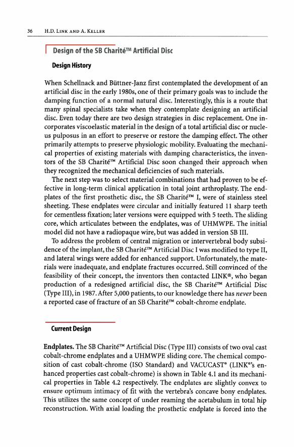
When Schellnack and Biittner-Janz first contemplated the development of an artificial disc in the early 1980s, one of their primary goals was to include the damping function of a normal natural disc. Interestingly, this is a route that many spinal specialists take when they contemplate designing an artificial disc. Even today there are two design strategies in disc replacement. One incorporates viscoelastic material in the design of a total artificial disc or nucleus pulposus in an effort to preserve or restore the damping effect. The other primarily attempts to preserve physiologic mobility. Evaluating the mechanical properties of existing materials with damping characteristics, the inventors of the SB ChariteM Artificial Disc soon changed their approach when they recognized the mechanical deficiencies of such materials.
The next step was to select material combinations that had proven to be effective in long-term clinical application in total joint arthroplasty. The endplates of the first prosthetic disc, the SB ChariteM I, were of stainless steel sheeting. These endplates were circular and initially featured 11 sharp teeth for cementless fixation; later versions were equipped with 5 teeth. The sliding core, which articulates between the endplates, was of UHMWPE. The initial model did not have a radiopaque wire, but was added in version SB Ill.
To address the problem of central migration or intervertebral body subsidence of the implant, the SB ChariteM Artificial Disc I was modified to type 11, and lateral wings were added for enhanced support. Unfortunately, the materials were inadequate, and endplate fractures occurred. Still convinced of the feasibility of their concept, the inventors then contacted LINK®, who began production of a redesigned artificial disc, the SB ChariteM Artificial Disc (Type Ill), in 1987. After 5,000 patients, to our knowledge there has never been a reported case of fracture of an SB ChariteM cobalt-chrome endplate.
Current Design
Endplates. The SB ChariteM Artificial Disc (Type Ill) consists of two oval cast cobalt -chrome endplates and a UHMWPE sliding core. The chemical composition of cast cobalt-chrome (ISO Standard) and VACUCAsr (LINK®'s enhanced properties cast cobalt-chrome) is shown in Table 4.1 and its mechanical properties in Table 4.2 respectively. The endplates are slightly convex to ensure optimum intimacy of fit with the vertebra's concave bony endplates. This utilizes the same concept of under reaming the acetabulum in total hip reconstruction. With axial loading the prosthetic endplate is forced into the

4 Biomechanics of Total Disc Replacement 37
Table 4.1. Materials - Chemical composition of Cobalt-Chrome Cast Alloy ISO 5832/IV and VACUCAST®
Specification % C % Cr % Mo % Ni % Fe % Si % Mn % Co
ISO 5832/IV max. 0.35
26.5 to 4.5 to max. max. max. max. Rest 66.4 30.0 7.0 2.5 1.0 1.0 1.0 to 60.2
N/mm'
1200+-_______ ---=:=--___ _ • VACUCAST
%
• ISO 58321IV
UTS 0,2 VS FS A5
Cobalt-Chromium-Molybdenum-Cast alloy A 5 = Elongation to Fracture UTS = Ultimate Tensile Strength 0,2 VS = 0,2 % Yield Strength FS = Fatique Strength
Table 4.2. Mechanical Properties of Cobalt -Chrome Cast Alloy ISO 5832/IV and VACU CAST®
concave receiving end of the vertebral body. Cement fixation of the SB ChariteM prosthesis has never been required.
Three anterior and three posterior teeth on the endplates provide sufficient immediate fixation with the underlying bone.
Between 1987 and 1997, the surface in contact with the bone was satin finished by corundum blasting. To improve the fixation of the endplates and ensure biologic fixation with a mineralized connection between bone and implants, the outer surfaces of the endplates received a bioactive double coating. This coating has been tested in a baboon study (McAfee et al. 2000; Chapter 6) and its efficacy has been demonstrated in cementless components for total hip and ankle arthroplasty.
The coating consists of three layers. There are two layers of commercially pure (CP) titanium; the first layer ensures a particularly strong bond between the cobalt-chrome endplate and the coating, and the second layer of plasma-

38 H.D. LINK AND A. KELLER
Table 4.3. Technical Data Chirulen®
Property UHMWPE* Units Test method
Average molecular weight 5xl06 g/mo)
Density (compression-moulded sheet) 930 kg/m3 ISO 1183 method A
Yield stress 21 MPa ISO 527
Tensile modulus 720 MPa ISO 527
Elongation@break <50 % ISO 527
Notched impact strength No break kT/m2 DI 53453
*UHMWPE, Chirulen<ri
sprayed titanium provides the desired pore size of 75-300 flm. The third coating consists of a layer of calcium phosphate. It is applied to the titanium surface in an electrochemical process.
The inside surfaces of the endplates, which face each other and articulate with the UHMWPE sliding core, consist of a concave spherical central section holding the convex body of the sliding core and a support rim surrounding it. This makes the core self-centering. With cyclical loading, the three components of the LINK® SB CharitfTM Artificial Disc will tend to realign themselves. The inside surfaces of the endplates are highly polished to optimally articulate and reduce friction with the UHMWPE sliding core.
Sliding Core. The sliding cores are manufactured of an ultra-high-molecularweight polyethylene specially manufactured for orthopedic use with mechanical properties described in Table 4.3.
The careful manufacturing and sterilizing processes (LINK® N-VAC®, Fig. 4.2) largely preserve the material's original properties. This results in good resistance to abrasion, as has been demonstrated by a recent RSA study in Sweden on total hips from different materials and following different sterilization methods (Digas et al. 2001). The body of the sliding core is surrounded by a rim, which prevents the margins of the superior and inferior metal endplates from coming into contact with each other, thus preventing metallic abrasion (Fig. 4.3).
Mechanical Testing
Requirements for Testing
The standardized materials used in the manufacture of the SB CharitfTM Artificial Disc have proven effective in decades of clinical use. Dental and or-

4 Biomechanics of Total Disc Replacement 39
By reduction of oxygen
the material is optimally
protected against degradation
(The volwn. of defonnatlon ""d .. cor and lcor
N.VAC" ConvenUon •. 1 Is approx. 2oo. It'S! UJan In convenUonal methods) meU.od
Alas. or vacuum lnmlraUon or nllrogen Phaseof .. eldb'g (sealing)
Figure 4.2. N· VAC® packaging/sterilization process to retain UHMWPE's properties
Figure 4.3. The body of the sliding core is surrounded by a rim, which prevents the margins of the superior and inferior metal endplates from coming into contact with each other
thopaedic devices made from these materials have been implanted in millions of patients worldwide without adverse effects. This makes additional biocompatibility tests superfluous. But how does the SB ChariteM Artificial Disc perform under load? What is the risk of fracture, cold flow, or abrasion with the components of the artificial disc?
According to the latest published data (Wilke 1999), the peak loads transmitted in the lumbar spine are approximately 4,000 to 4,200 Newtons. Are the endplates and UHMWPE sliding core of the SB Charite™ Artificial Disc able to withstand such loads?
From 1987 to December 2002, we recorded approximately 5,300 implantations performed in 27 countries throughout the world. Although in some cas-

40 H.D. LINK AND A. KELLER
es, the placement of the implants was unfavorable with respect to load transfer, there have been no reports of any implant fracture or other material or design related incident for the cobalt-chrome endplates. Theoretically, loads between 142,500 Nand 237,500 N would be required to distort an endplate, depending on its size. This is due to the material parameters, the strong design of the endplates, and to a certain extent, to their specific material and machining quality.
The VACUCASr cast cobalt-chrome-molybdenum alloy is especially pure in its composition (see Table 4.1), and its mechanical properties exceed applicable standards (see Table 4.2). The finish is obtained using a proven high polish process, which is used in many other cobalt-chrome articulating components in total joint systems.
The UHMWPE sliding core is obviously the weakest link in the artificial disc implant system. In this regard, it is quite similar to the polyethylene components in total hip or knee arthroplasty. Nevertheless, no alternate material has yet been found that combines all the positive characteristics of UHMWPE, especially its damping and handling characteristics. This material has remarkable viscoelastic recovery (Lee et al. 1998), which is advantageous for the artificial disc as it allows the surgeon to expect acceptable long-term results even when the implant has not been ideally positioned.
However, only biomechanical testing under defined conditions can be used to predict whether the UHMWPE sliding core can withstand the loads transmitted through the lumbar spine. Consequently, several tests have been performed over time to address this question.
Types ofTesting
Various types of testing may be performed using different setups depending on which assumptions the biomechanical engineer decides to specifically analyze. For total joint arthroplasty components and bone implants, it is advisable to initially test the mechanical stability of the finished parts in the manufacturing facility by simple means such as "one time load-to-failure" to determine bending, fracture, or shear strength.
Aside from these basic tests, static, dynamic, or functional tests under defined laboratory conditions are required where compliance with an existing or proposed standards is an issue. Such testing often includes the use of a water bath, Ringers lactate, calf serum, or saline solution to simulate lubricated conditions with normal body temperature.
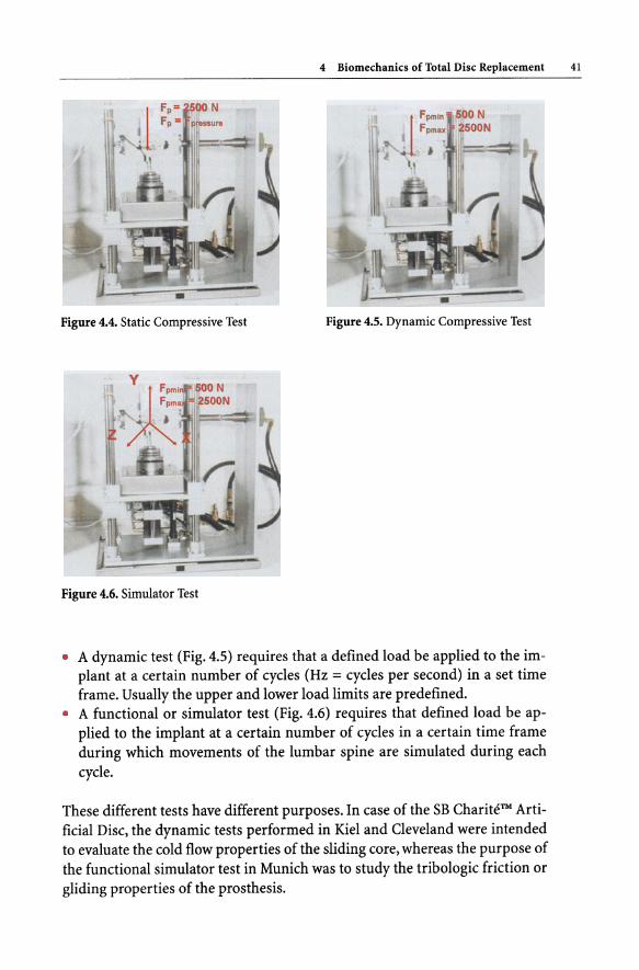
Here is an overview of the three most common test methods for orthopedic implants: • A static test (Fig. 4.4) requires that a defined load be applied to the implant
in a specified time frame.
4 Biomechanics of Total Disc Replacement 41
Figure 4.4. Static Compressive Test Figure 4.5. Dynamic Compressive Test
Figure 4.6. Simulator Test
• A dynamic test (Fig. 4.5) requires that a defined load be applied to the implant at a certain number of cycles (Hz = cycles per second) in a set time frame. Usually the upper and lower load limits are predefined.
• A functional or simulator test (Fig. 4.6) requires that defined load be applied to the implant at a certain number of cycles in a certain time frame during which movements of the lumbar spine are simulated during each cycle.
These different tests have different purposes. In case of the SB ChariteM Artificial Disc, the dynamic tests performed in Kiel and Cleveland were intended to evaluate the cold flow properties of the sliding core, whereas the purpose of the functional simulator test in Munich was to study the tribologic friction or gliding properties of the prosthesis.

42 H.D. LINK AND A. KELLER
This section is intended to provide the spinal surgeon with an overview of the specific mechanical tests performed on the SB CharitfTM Artificial Disc and their results. Therefore, the test conditions and setups are only briefly described. For detailed information, we refer the reader to the complete test reports.
Bench top testing -/lCold flow,;/lpoly disease'; and /lperiprosthetic osteolysis/l are NOT MAJOR FACTORS with the SB Charite™ Artificial Disc
The theoretical evaluation of possible cold flow in the sliding core of the SB Charite™ Artificial Disc may be based on a few essential figures: • The cold flow limit ofUHMWPE used for the sliding core is 22 N/mm2. This
yields the following figures, which represent the load limit for avoiding cold flow (Table 4.4).
• The contemporary literature (Wilke 1999; Bogduk, chapter 3) mentions maximum loads in the lumbar spine of approximately 4,000 N (for a test person bending forward and lifting a 20 kg load; Wilke cites 4,140 N).
• The maximum load according to Wilke is 4.5 times the normal load. • To calculate the cold flow limit in the various sizes of prosthesis, one multi
plies the size in mm2 of the contact area between the endplate and UHMWPE sliding core by 22. This yields the following figures, which represent the load limit for avoiding cold flow (see Table 4.4).
The safety margin for the sliding core under normal load conditions is determined by the calculation shown in Table 4.5. Consequently, the safety margin for avoiding cold flow under normal load conditions lies between a factor of 3.3 for sliding core size 1 and a factor of 5.71 for sliding core size 5. Remember that size 1 and core size 7.5 thickness are very rarely ever used in clinical practice. This is only a rough calculation, and many other parameters such as the thickness of the core, shape of the contact zone, etc. are involved in the mechanics of cold flow.
The wear factor is determined by the formula shown below (Barbour et al. 1997). A load is present, but the sliding distance is nearly zero due to the constraints of the facets and soft-tissue structures.
Volume lost due to wear 3/N Wear Factor = = mm m
Sliding distance x Load
Clinical evaluations of users of the SB CharitfTM Artificial Disc have shown that abrasion does not occur when parallel positioning of properly sized endplates has been achieved (Staudte and Lindenfelser 1998). Abrasion occurs only when

4 Biomechanics of Total Disc Replacement 43
Table 4.4. Load limits of the various artificial disc sliding core sizes (calculated for contact with one endplate)
Artificial Disc Contact areas N-Load limit at 22 N/mm 1
(UHMWPE sliding core/endplates)
Size 1 = 138.23 mm2
Size 2 = 163.36 mm2
Size 3 = 188.49 mm2
Size 4 = 213.62 mm2
Size 5 = 238.76 mm2
3,041
3,594 4,147
4,700 5,253
Table 4.5. Load on the lumbar disc - Specific load of UHMWPE core per size
Prostheses Maximum Contact Specific Specific Safety load acc. areas maximum normal margin to Wilke load load
Size 1 4140 : 138.23 = 29.95 : 4.50 = 6.66 N = 3.30 x
Size 2 4140 : 163.36 = 25.34 : 4.50 = 5.63 = 3.90 x
Size 3 4140 : 188.49 = 21.96 : 4.50 = 4.88 = 4.50 x
Size 4 4140 : 213.62 = 19.38 :4.50 = 4.31 N = 5.IO x
Size 5 4140 : 238.76 = 17.34 :4.50 = 3.85 = 5.71 x
~ Load limit of UHMWPE 22 Imm2
Following Wilke the maximum load is 450% of the normal load (relaxed standing 100%); consequently the maximum figure have to be divided by 4.50 to calculate normal load: = Normal load (100%) Imm2 = Maxjmum load N: 4.50
the load is concentrated on a small region of the core due to incorrect positioning or too small size of implant. It is interesting to note that no signs of "polyethylene disease" or periprosthetic osteolysis from such abrasion have been detected in the tissues surrounding the artificial disc, even where particles of polyethylene were found. This is most probably due to the absence of synovia (Sibbit 1999; Goldring et al. 1986) in the area where the prosthesis is positioned.

44 H.D. LINK AND A. KELLER
Dynamic Testing in Kiel, Germany, and Cleveland, Ohio, USA
As a prerequisite for an investigational device exemption (IDE) to achieve pre-market approval, the U.S. Food and Drug Administration (FDA) required the dynamic testing described below to "determine the dynamic properties and provide an estimate of permanent deformation, and failure location of the UHMWPE sliding core in pure compression" (Ahrens 1999). The four testing parameters were as follows:
Size 2 parallel plates (Part 75-6400/02) with a 7.5mm sliding core (Part 75-6412/02) under 2.5 kN compressive load. Size 2 parallel plates (Part 75-6400/02) with a 7.5mm sliding core (Part 75-6412/02) under 4.5 kN compressive load. Size 2 parallel plates (Part 75-6400/02) with a 9.5mm sliding core (Part 75-6412112) under a 2.5 kN compressive load.
• Size 2 parallel plates (Part 75-6400/02) with a 9.5mm sliding core (Part 75-6412112) under a 4.5 kN compressive load.
The tests were conducted over 24 hours and were divided in three phases. The first phase lasted 4 hours, cycling at a frequency of 0.5 Hz. The second phase lasted 12 hours, cycling at 0.01666 Hz. The third phase lasted 8 hours, cycling at 0.0011 Hz. The recovery time was set at 4 hours. The tests were performed at 370 Celsius ±2o Celsius in Ringer's solution in deionized water. A minimum of five specimens per load and height were tested.
Measurements of every specimen were obtained before and after testing, at each of four different zones: • Maximum height of the core at the center • Height of the core flanges
Diameter of the core measured in line with the junction of the radiopaque WIre Diameter of the core measured perpendicular to the junction of the radiopaque wire
The testing included strain and strain versus time calculations. These calculations specify the estimated total strain in the UHMWPE sliding core after five and ten years of implantation.
It is interesting to note that the tests were performed with size 2 implants, the smallest of the sizes currently used (disregarding size 1, which has been removed from the standard product range), and the 7.5 and 9.5 mm UHMWPE sliding cores, which again represent the smaller sizes. Most remarkable is that the loads applied were 2.5 and 4.5 kN, whereas the current literature cites peak loads ranging from 4 to 4.2 kN. Table 4.5 shows the test results.

4 Biomechanics of Total Disc Replacement 45
Table 4.6. Dynamic compressive testing of 7.5 and 9.5 mm Size 2 UHMWPE cores
Results Kiel" Cleveland**
Despite the high load of 2.5 and 4.5 kN used:
• one of the specimen tested failed
• Tertiary creep was not observed
• Drastic dimensional changes, like in plastic collapse, were not observed
• Dimensional changes were found to be low
• For all testing phases and loads, the creep rates were found to be low
• The results of this study indicate that the maximum expected permanent deformation after 10 years implantation is 0.403 mm and 0.738 mm for the 7.5 mm and 9.5 mm cores, respectively.
• These values correspond to an expected decrease in core heights of less than 8%
• Therefore, under normal in vivo conditions the permanent deformation of the core is not expected to reduce the available articulating surface or result in premature failure of the device due to significant cold flow or delamination
• These findings from the dynamic mechanical testing confirm the radiographic observations of patients that have been implanted with the device at an average follow-up of six years
,. University of Applied Sciences, Institute for Materials and Surface Technology, Kiel/Germany
** Orthopaedic Research Laboratory, Mt. Sinai Medical Centre, Cleveland/Ohio
The bench top cyclical tests in two independent testing sites in two different countries reach the same conclusion - cold flow is not a major factor with the SB ChariteM III prosthesis.

46 H.D. LINK AND A. KELLER
Functional Testing in Munich, Germany
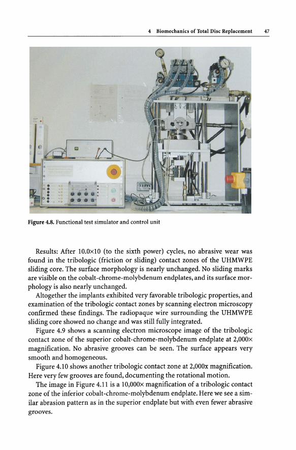
For the functional or simulator test, the small size 2 implants were used as in the Kiel and Cleveland dynamic testing, together with the most commonly used sliding core, the medium size 9.5mm sliding core. The test duration was set a 1O.OxlO (to the sixth power) cycles. Additionally, a scanning electron microscopy examination of all components was performed.
The superior and inferior endplates were attached to the simulator adapter by means of acrylic bone cement. Then the UHMWPE sliding core was positioned. The dynamic test was performed at a maximum load of 2.5 kN and a minimum load of 0.5 kN (sinusoidal) with the following functional movements Fig. 4.7 (Table 4.7).
The fluid test medium was calf serum (25±20/0) diluted with deionized water, at 37 degrees Celsius ± 1 degree Celsius. Figure 4.8 shows the simulator together with its control unit.
Table 4.7. Test Conditions
X-axis
Y-axis
Z-axis
Sagittal rotation (flexion/extension)
Axial rotation
Lateral bending
Frequency: 1 HzO, 1 Hz.
Figure 4.7. Simulator Test
+4 degrees/-2 degrees
+ 1 degree/-l degree
+2 degrees/-2 degrees
.... : , ....
4 Biomechanics of Total Disc Replacement 47
Figure 4.8. Functional test simulator and control unit
Results: After 10.0xlO (to the sixth power) cycles, no abrasive wear was found in the tribologic (friction or sliding) contact zones of the UHMWPE sliding core. The surface morphology is nearly unchanged. No sliding marks are visible on the cobalt-chrome-molybdenum endplates, and its surface morphology is also nearly unchanged.
Altogether the implants exhibited very favorable tribologic properties, and examination of the tribologic contact zones by scanning electron microscopy confirmed these findings. The radiopaque wire surrounding the UHMWPE sliding core showed no change and was still fully integrated.
Figure 4.9 shows a scanning electron microscope image of the tribologic contact zone of the superior cobalt-chrome-molybdenum endplate at 2,000x magnification. No abrasive grooves can be seen. The surface appears very smooth and homogeneous.
Figure 4.10 shows another tribologic contact zone at 2,000x magnification. Here very few grooves are found, documenting the rotational motion.
The image in Figure 4.11 is a 10,000X magnification of a tribologic contact zone of the inferior cobalt -chrome-molybdenum endplate. Here we see a similar abrasion pattern as in the superior endplate but with even fewer abrasive grooves.

48 H.D. LINK AND A. KELLER
Figure 4.9. Scanning electron microscopic image of the tribologic contact zone of the superior cobalt-chromemolybdenum endplate at 2,OOO-power magnification
Figure 4.10. Another tribologic contact zone at 2,OOO-power magnification. Here very few grooves are found, documenting the rotational motion
Figure 4.11. 1O,OOO-power magnification of a tribologic contact zone of the inferior cobalt -chromemolybdenum endplate
---10FM 3 44 046 S
---1~ 3 44 048 8
---2t'1'1 3 44 cr.5S 8

Figure 4.12. The superior polar area of the UHMWPE sliding core at 200-power magnification
Figure 4.13. The superior polar area of the UHMWPE sliding core at I,OOO-power magnification
Figure 4.14. The superior polar area of the UHMWPE sliding core at 2,OOO-power magnification
4 Biomechanics of Total Disc Replacement 49

50 H.D. LINK AND A. KELLER
Figure 4.15. A tribologic contact area of the inferior aspect of the UHMWPE sliding core at 200-power magnification
Figure 4.16. A tribologic contact area of the inferior aspect of the UHMWPE sliding core at 2,OOO-power magnification
A few micron-size impurities may also be seen between the crystals. These impurities are due to the casting process and are responsible for the abrasive grooves. They are usually found under extreme magnification in the tribologic contact zone in cast metal components of hip or knee implant systems.
Figures 4.12,4.13, and 4.14 show the superior polar area of the UHMWPE sliding core at 200x, I,OOOx, and 2,OOOx magnification.
Figures 4.15 and 4.16 show a tribologic contact area of the inferior aspect of the UHMWPE sliding core at 200-power and 2,OOO-power magnification.
The examination of the surfaces of the sliding core revealed only fine abrasive grooves and abrasive flags (which might later become debris) of very limited size. Further examination of the margins of the UHMWPE sliding core reveals circular abrasive grooves. At higher magnification, only a few surface

4 Biomechanics of Total Disc Replacement SI
irregularities measuring 20llm are visible. The conclusion was that there was no abrasive wear over 80-90% of the tribologic contact area. Examination detected only extremely mild abrasive wear of negligible volume. The results of this tribologic examination are very favorable, especially in light of the demanding functional testing with lO million cycles. This degree of abrasive wear, visible only after 10 million cycles, and visible using electron microscopy is not felt by tribologic engineers to be clinically significant.
~. . DIscussion
The theoretical and biomechanical evaluations of the LINK® SB Charitt?M Artificial Disc indicate that the weakest link of the prosthesis, the UHMWPE sliding core, can be expected to withstand the loads transmitted through the lumbar spine. However, clinical follow-up and biomechanical test have demonstrated that the safety margin in the sliding core is not sufficiently large to compensate for every error in component size selection or prosthesis placement. Especially in cases where too small an implant is poorly positioned, the cumulative effect of both problems can possibly lead to polyethylene destruction. It is reassuring that the anterior column of the lumbar spine appears to be one place in the human body where periprosthetic osteolysis is not a major factor, due to lower ranges of motion and an absence of synovium compared to the hip and the knee joint.
The correlation between poor placement and implant destruction is not new and can be found in the literature on total diarthrodial joint arthroplasty. To achieve a long-term fully functional disc arthroplasty, the spinal surgeon must make every effort to avoid the two well-known early errors, selection of too small an implant and mal-alignment of the artificial disc.
Intra-operative fluoroscopy in two planes allows surgeons to recognize possible shortcomings and enables them to correct such errors before the patient leaves the operating room. If the issues mentioned in the previous sections are taken into consideration and with good operative indications, the patient receiving an artificial disc can generally expect to benefit from a motion-preserving arthroplasty at least to the degree as conventional total joint recipients. If the artificial disc should subsequently fail, posterior spinal fusion and pedicle screws, usually with the artificial disc left in place, still remains a salvage option.

S2 H.D. LINK AND A. KELLER
I Referentes
Ahrens, JE (1999) Mechanical evaluation of the SB Charite Artificial Disc: estimation of permanent deformation. Internal Report
Barbour PSM, Barton DC, Fisher J (1997) The influence of stress conditions on the wear of UHMWPE for total joint replacement. Journal of Material Science: Material in Medicine 8: 603-611
Bogduk N (1997) Clinical anatomy of the lumbar spine and sacrum, 3rd edn. Churchill Livingstone, London Edinburgh, pp 71-73
Digas G et al. (2001) Increased femoral head penetration using polyethylene sterilized with ethylene oxide. Poster exhibition, AAOS, San Francisco
Goldring SR, J asty M, Roelke MS, Rourke CM, Bringhurst FR, Harris WH (1986) Formation of a synovial-like membrane at the bone-cement interface. Arthritis Rheumatism 29(7): 836-842
Lee K-Y et al. (1998) Viscoelastic recovery of creep-deformed ultra-high molecular weight polyethylene (UHMWPE). ASTM Special Technical Publication 1307:30-36
McAfee PC et al. (2000) Biologic study of ingrowth - SB Charite. IDE Investigators Meeting, New Orleans
Sibbit WL Jr (1999) The normal and the diseased joint. In: Bronner F, Worel RV (eds) Orthopaedics. Principles of Basic and Clinical Science. CRC Press, Florida, pp 141-163
Staudte HW, Lindenfelser R (1998) Personal communications Wilke H-J, Neef P, Caimi M, Hoogland T, Claes L (1999) New Intradiscal Pressure Measure
ments in vivo During Daily Acitivities. Spine 24(8): 755-762