Embed Size (px)
Citation preview

7/26/2019 4 Composite Slurry Wall and Liner
http://slidepdf.com/reader/full/4-composite-slurry-wall-and-liner 1/10
Geo-Frontiers 2011 Dallas TX
March 13-16, 2011
Composite Slurry Wall and Liner—A Full Scale Test
D. Berthier
1
; C. R. Ryan
2
, M. ASCE, P.E., D. G.E; P. J. P. Vincent
1
, MIE Aust1Menard Bachy, 13-15 Lyon Park Road, 2113, Lyon Park Road, NSW, Australia, PH
(61) 2 9491 7100, FAX (61) 9491 7111, email [email protected] 2Geo-Solutions Inc., 1250 Fifth Ave., New Kensington PA 15068; PH (724) 335-
7273; FAX (724) 335-7271, email: [email protected]
ABSTRACT
As part of the plan to increase the capacity of the Port of Brisbane,
reclamation of a total area of 235 ha is in progress. The main geotechnical issue at thesite is the extremely soft material dredged from the Brisbane River and Moreton Bay
shipping channels. Over part of the reclamation area, Menard Bachy was selected bythe Port of Brisbane Corporation to carry out deep soft ground consolidation, usingthe method of Vacuum Consolidation. In 2007, a trial area of 1.5 ha was first
implemented. Following successful completion of the trial, a second and larger project was begun in 2009. The new single cell area of 9.3 ha is currently under
vacuum depressurization and the soil consolidation is expected to be complete by
early 2011.A significant feature in the vacuum system adopted is the 15m deep soil-
bentonite cut-off wall incorporating a high-density polyethylene (HDPE) liner, whichis required at the periphery, to isolate the vacuum areas over the depth of the
permeable layers in the subsurface profile. To ensure the confinement required for the
depressurization, the slurry wall and incorporated liner are joined to a surface capHDPE liner to complete an air and water tight seal around and over the block of soil.
The initial trial incorporating the deep cut-off wall was a first in Australia andwas a success in terms of both outcome and execution with depressurization, under
the vacuum membrane, being maintained constantly in the range of -0.80/-0.70 bars
over a long period of time of 18 months. Confinement work on the current project,which is taking place over a significantly larger scale and using improved technique,
is currently in progress.The ability of Soil-Bentonite slurry walls incorporating HDPE liners to
perform as air-tight and water-tight barriers under high pressure differential (0.8 to
0.7 bars) and subjected to significant deformation has been tested on these large scale
projects. The barrier system has proven to be effective for considerable periods oftime.
INTRODUCTION
The purpose of the projects in Brisbane, Australia was to improve soft soils
for a future expansion of the port facilities (Boyle, De Bok et al., 2007). Muddredged from the harbor had been previously placed in large spoil areas inside

7/26/2019 4 Composite Slurry Wall and Liner
http://slidepdf.com/reader/full/4-composite-slurry-wall-and-liner 2/10
containment dikes and allowed to dewater over time. Clayey deposits were still very
soft after a period of several years of draining under their own weight. Moreover, theexisting ground under the sea bed consists of soft compressible clay to significant
depths (up to 45m). The projects are using a technology called VacuumConsolidation to pre-consolidate the soils in advance of construction (Masse,
Spaulding et al., 2001). Vacuum Consolidation is an evolution of conventionalsurcharge consolidation and also uses a pattern of vertical drains to accelerate thereduction in water content and thus force accelerated settlement of soft materials.
Vacuum Consolidation requires that the block of soil treated be completely confinedso that atmospheric pressure can be used to increase stress within the material which
in turn will induce its accelerated consolidation.
The seal for the bottom of the Vacuum enclosure is usually, as was the case
here, a natural low permeability formation such as a clay layer. An HDPE liner isinstalled over the treated area to seal the top surface. Finally, the perimeter of the
vacuum cell needs to be sealed to prevent transmission of water below the water table
and infiltration of air above it. On the Port of Brisbane project, the numerousinterbedded layers of sand within the upper clay layer combined with the predicted
variation in ground water table level over time due to the settlement induced by theconsolidation process dictated the use of a flexible cut off wall (soil bentonite)
coupled with an HDPE liner over the upper 8-10 meters. A sketch of the Brisbane
vacuum and peripheral wall layout is shown below (Fig. 1).
Figure 1. Simplified cross section of Vacuum layout
Once the areas were capped and the vertical barrier liners material were joined
to the horizontal capping liners, the entire area was subjected to a vacuum of 0.8 bars,
where quality monitoring was provided by instrumentation designed to detect andlocate defects in the system.

7/26/2019 4 Composite Slurry Wall and Liner
http://slidepdf.com/reader/full/4-composite-slurry-wall-and-liner 3/10
There were two areas treated by Vacuum Consolidation, one trial in 2007 of
1.5Ha involving the use of a 750m long cut off wall over an approximate area of7,000m
2. In 2009, a full scale production project of 9.3Ha was performed requiring
the installation of a 1,250m long cut off wall enclosing an approximate area of19,000m
2 (Berthier, Ameratunga et al., 2009). The trial is the L-shaped area shown
on the left picture below (Fig. 2); the second (production) area is shown on the picture on the right below.
Figure 2. Aerial views of the Brisbane site, trial (left), production area (right)
An interesting aspect of these vacuum projects was that they afforded the
opportunity to test the behavior of the barrier systems over a considerable area andthroughout an extended pumping duration. Further, different methods of placing and
jointing of the HDPE liner were used in the two projects, providing additionalopportunity to evaluate the relative effectiveness of both systems.
Importantly, the data presented herein provide confidence in the lapped
jointing of the liner material in the slurry wall backfill under considerable stress andstrains, whilst affording considerable savings over other systems.
COMPOSITE SLURRY WALLS
Most slurry walls are backfilled with a homogeneous blend of soil-bentonite
(SB) or soil-cement-bentonite (SCB) or cement-bentonite (CB) mixtures. Thesemixtures are designed to stop the lateral movement of groundwater. Occasionally,
due to site conditions which might include possible gas permeation, desiccation or
severe chemical contamination, any of which might cause concern as to the
effectiveness of the conventional backfill blends, there might be a need for further protection. In a small number of cases, an additional barrier may be inserted into thewall for extra safety. Materials used for the secondary barrier have included plastic
and steel sheet piles but most commonly, high density polyethylene (HDPE) liner
material is used. Examples of projects where composite slurry walls have been usedinclude:
Methane containments at landfills

7/26/2019 4 Composite Slurry Wall and Liner
http://slidepdf.com/reader/full/4-composite-slurry-wall-and-liner 4/10
Desert conditions where flash floods might apply water quickly to adesiccated wall.
Highly contaminated groundwater containments where conventional blendsmight fail.
Different methods have been used to establish continuity between the plasticsheets and these methods can have a significant impact on the cost of the project.
One method uses an interlocking joint similar to a sheet pile. For the interlockingsystem, the sheets are slid into position vertically, usually using a temporary steel
frame. (Fig. 3)
Figure 3. Installation of liner in slurry wall using temporary steel frame
A second method is to overlap the panels with no physical connection. With thismethod, the pressure of the backfill provides the seal between the two sheets (Fig. 4).

7/26/2019 4 Composite Slurry Wall and Liner
http://slidepdf.com/reader/full/4-composite-slurry-wall-and-liner 5/10
Figure 4. Liner being placed with overlapped joints
CONSTRUCTION METHODS USED AT THE PORT OF BRISBANE
The trench for the cut-off was excavated to a depth of approximately 15
meters with an extended-stick 80 ton excavator. Bentonite slurry was used to support
the excavation through the extremely weak clays and saturated sands as shown below(Fig. 5).
Figure 5. Excavating the trench supported by bentonite slurry
7/26/2019 4 Composite Slurry Wall and Liner
http://slidepdf.com/reader/full/4-composite-slurry-wall-and-liner 6/10
During the trial project in 2007, the liner was placed using adjacent vertical
sheets 10 meters wide. The base of the liner was weighted and each panel waslowered into the slurry with an approximate 2.0 meters overlap over the previous
panel. Panels were 8 meters deep, which was sufficient to extend below the sea level.Once the panels were placed, the trench was backfilled with soil-bentonite mixed
material. Panels being placed during the trial are shown below (Fig. 6).
Figure 6. Placing HDPE panels vertically with overlap
For the larger second project, a horizontal roller was developed which allowedfor an increase in placement productivity and reduced the number of overlap joints
required (Fig. 7). The depth of the HDPE liner was 7 meters and only one overlap
was required every 200 meters of wall.

7/26/2019 4 Composite Slurry Wall and Liner
http://slidepdf.com/reader/full/4-composite-slurry-wall-and-liner 7/10
Figure 7. Placing the HDPE liner with a horizontal roller.
PROJECT DATA
The interesting aspect of these two projects is that they represented a very
unusual test of a slurry wall system constructed under full scale conditions and
operating over long periods of time. The cells were subjected to vacuum pressure for periods exceeding 18 months (Trial) and 10 months (currently still under way for the
Main area) and extensive data were collected from the instrumentation internal to the blocks at various points around the site. Vacuum depression was measured beneath
the overlying HDPE membrane and at various depths within the Vertical
Transmission Pipes to ensure the depression was applied throughout the entire soil profile and the results are shown in (Fig. 8).

7/26/2019 4 Composite Slurry Wall and Liner
http://slidepdf.com/reader/full/4-composite-slurry-wall-and-liner 8/10
Figure 8. Vacuum pressures at various elevations vs. time on production project
The above plot for the trial section shows that the pressures were lowered to
approximately negative 0.7 to 0.8 atmospheres and maintained over 18 months.Interestingly, when some vacuum pumps breakdowns occurred, there was an
immediate reaction which translated in the loss of depression but vacuum was
restored quickly after pump repair was completed.
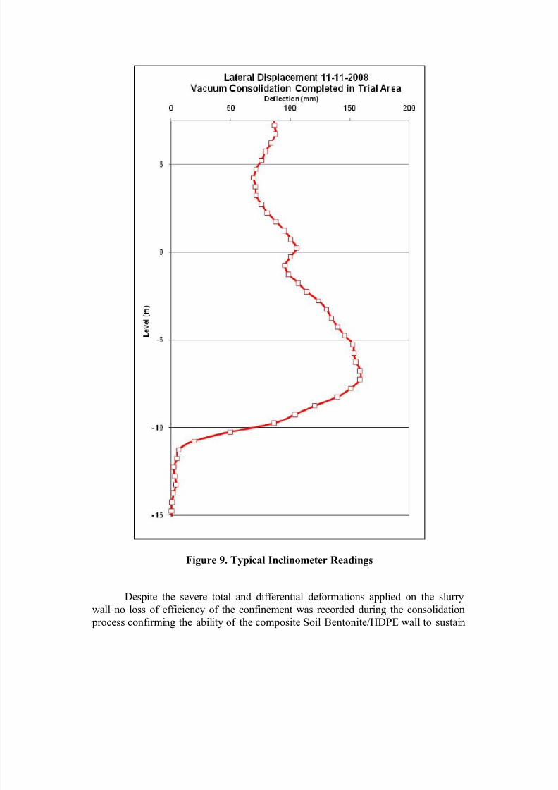
As a result of the pressure application to the cells, they demonstratedsignificant vertical and lateral deformations along their boundaries. Vertical
settlements due to consolidation exceeded 2.5 meters and in the vicinity of the
composite slurry wall there were several inclinometers which measured horizontalwall deformations up to 200mm. Typical inclinometer data are shown on the
following plot (Fig. 9).
7/26/2019 4 Composite Slurry Wall and Liner
http://slidepdf.com/reader/full/4-composite-slurry-wall-and-liner 9/10
Figure 9. Typical Inclinometer Readings
Despite the severe total and differential deformations applied on the slurry
wall no loss of efficiency of the confinement was recorded during the consolidation
process confirming the ability of the composite Soil Bentonite/HDPE wall to sustain

7/26/2019 4 Composite Slurry Wall and Liner
http://slidepdf.com/reader/full/4-composite-slurry-wall-and-liner 10/10
such displacements whilst maintaining extremely low permeability (between 10-8
m/s
and 10-9
m/s).
CONCLUSIONS
The implementation of vacuum consolidation incorporating a 15m deep soil bentonite cut-off wall, a first in Australia, has proved to be very successful. De- pressurization under the vacuum membrane was constantly retained, in the range of -
0.80/-0.70 bars (atmospheres) throughout the extended vacuum pumping phase.
The Port of Brisbane Vacuum Consolidation projects represented an unusual
opportunity to evaluate a full-scale test of a pressurized slurry wall system. Twomethods of installing the liner material were used and evaluated.
Conclusions from this project are as follows:
The slurry wall system was an effective way of providing lateral air-tight andwater-tight containments, both above and below the water table.
The overlapping method of creating the joints formed an effective seal, even
under conditions of extreme stress and deformation.
Both the vertical and horizontal roller methods of HDPE sheet installation
resulted in air-tight installations.
REFERENCES
Berthier, D. Boyle, P. Ameratunga, J. De Bok, C. and Vincent, P. “A successful trial
of vacuum consolidation at the Port of Brisbane”, 2009 ISGI SingaporeBoyle, P, Amaratunga, J, De Bok, C, and Tranberg, B, “Planning for the Future-
Ground improvement trials at Port of Brisbane”, Proc. Coasts and Ports
Conference-PIANC, Melbourne, 2007.Masse, F. Spaulding, C. Wong, I.C. Varaksin, S. “Vacuum consolidation – A review
of 10 years of successful development”, Geo-Odyssey, Blacksburg VA, USA(2001).