Embed Size (px)
Citation preview

Introduction 1
Safety instructions 2
Description 3
Installation 4
Parameter assignment/Addressing
5
Configuring 6
Maintenance, service and disposal
7Interrupt, error, and system messages
8
Troubleshooting/FAQs 9
Technical data 10
Dimension sheets 11
Appendix A
ESD directives B
List of abbreviations C
SENTRON
Expansion module PAC PROFIBUS DP
Manual
06/2007 A5E01168846B-02
Safety Guidelines This manual contains notices you have to observe in order to ensure your personal safety, as well as to prevent damage to property. The notices referring to your personal safety are highlighted in the manual by a safety alert symbol, notices referring only to property damage have no safety alert symbol. These notices shown below are graded according to the degree of danger.
DANGER indicates that death or severe personal injury will result if proper precautions are not taken.
WARNING indicates that death or severe personal injury may result if proper precautions are not taken.
CAUTION with a safety alert symbol, indicates that minor personal injury can result if proper precautions are not taken.
CAUTION without a safety alert symbol, indicates that property damage can result if proper precautions are not taken.
NOTICE indicates that an unintended result or situation can occur if the corresponding information is not taken into account.
If more than one degree of danger is present, the warning notice representing the highest degree of danger will be used. A notice warning of injury to persons with a safety alert symbol may also include a warning relating to property damage.
Qualified Personnel The device/system may only be set up and used in conjunction with this documentation. Commissioning and operation of a device/system may only be performed by qualified personnel. Within the context of the safety notes in this documentation qualified persons are defined as persons who are authorized to commission, ground and label devices, systems and circuits in accordance with established safety practices and standards.
Prescribed Usage Note the following:
WARNING This device may only be used for the applications described in the catalog or the technical description and only in connection with devices or components from other manufacturers which have been approved or recommended by Siemens. Correct, reliable operation of the product requires proper transport, storage, positioning and assembly as well as careful operation and maintenance.
Trademarks All names identified by ® are registered trademarks of the Siemens AG. The remaining trademarks in this publication may be trademarks whose use by third parties for their own purposes could violate the rights of the owner.
Disclaimer of Liability We have reviewed the contents of this publication to ensure consistency with the hardware and software described. Since variance cannot be precluded entirely, we cannot guarantee full consistency. However, the information in this publication is reviewed regularly and any necessary corrections are included in subsequent editions.
Siemens AG Automation and Drives Postfach 48 48 90327 NÜRNBERG GERMANY
Ordernumber: A5E01168846B-02 Ⓟ 08/2007
Copyright © Siemens AG 2007. Technical data subject to change
PAC PROFIBUS DP Manual, 06/2007, A5E01168846B-02 3
Table of contents 1 Introduction................................................................................................................................................ 5
1.1 Purpose of this document ..............................................................................................................5 1.2 Orientation aids..............................................................................................................................5 1.3 Manual version...............................................................................................................................6 1.4 Scope of supply .............................................................................................................................6 1.5 Contents of the CD for the SENTRON PAC power meter.............................................................6 1.6 Technical support...........................................................................................................................7 1.7 Further documentation...................................................................................................................8
2 Safety instructions ..................................................................................................................................... 9 2.1 Safety instructions..........................................................................................................................9
3 Description............................................................................................................................................... 11 3.1 Area of application .......................................................................................................................11 3.2 Features .......................................................................................................................................11 3.3 Tasks............................................................................................................................................12 3.4 Structure.......................................................................................................................................13 3.5 PROFIBUS functions ...................................................................................................................14
4 Installation ............................................................................................................................................... 15 4.1 Procedure for installation and commissioning .............................................................................15 4.2 Unpacking ....................................................................................................................................16 4.3 Installation and connection ..........................................................................................................17 4.4 Equipotential bonding ..................................................................................................................20 4.5 Measures to be performed prior to start-up .................................................................................21 4.6 Disassembly.................................................................................................................................21
5 Parameter assignment/Addressing.......................................................................................................... 23 5.1 Cyclic data exchange...................................................................................................................23 5.1.1 Introduction ..................................................................................................................................23 5.1.2 Basic type 1..................................................................................................................................24 5.1.3 Basic type 2..................................................................................................................................24 5.1.4 Freely definable basic type ..........................................................................................................25 5.1.5 Digital status information in the cyclic channel ............................................................................26 5.1.6 Control bytes................................................................................................................................27 5.1.7 Measured variables......................................................................................................................29 5.1.8 Working measured variables in double and float format .............................................................33 5.1.9 Limit values ..................................................................................................................................34 5.1.10 Digital input statuses and output statuses ...................................................................................35
Table of contents
PAC PROFIBUS DP 4 Manual, 06/2007, A5E01168846B-02
6 Configuring .............................................................................................................................................. 37 6.1 Default settings ........................................................................................................................... 37 6.2 Configuration scenarios .............................................................................................................. 37 6.3 Changing the address ................................................................................................................. 38 6.4 Configuring by means of the GSD file......................................................................................... 39
7 Maintenance, service and disposal .......................................................................................................... 47 7.1 Cleaning ...................................................................................................................................... 47 7.2 Repair.......................................................................................................................................... 48 7.3 Disposal....................................................................................................................................... 48
8 Interrupt, error, and system messages .................................................................................................... 49 8.1 Diagnostics concept .................................................................................................................... 49 8.2 Slave diagnostics ........................................................................................................................ 49 8.3 Diagnostics LED.......................................................................................................................... 50 8.4 Structure of the device statuses.................................................................................................. 51 8.5 Structure of the device diagnostics ............................................................................................. 52 8.6 Device diagnostic messages ...................................................................................................... 54 8.7 Initializing the module.................................................................................................................. 55
9 Troubleshooting/FAQs............................................................................................................................. 59 9.1 Power failure ............................................................................................................................... 59
10 Technical data ......................................................................................................................................... 61 10.1 Standards.................................................................................................................................... 61 10.2 Technical data............................................................................................................................. 62 10.3 Communication interface ............................................................................................................ 64 10.4 Labeling....................................................................................................................................... 65
11 Dimension sheets .................................................................................................................................... 69 11.1 Dimension sheets........................................................................................................................ 69
A Appendix.................................................................................................................................................. 71 B ESD directives ......................................................................................................................................... 73
B.1 Electrostatic sensitive devices (ESD) ......................................................................................... 73 C List of abbreviations................................................................................................................................. 75
C.1 Abbreviations .............................................................................................................................. 75 Glossary .................................................................................................................................................. 77 Index........................................................................................................................................................ 79
PAC PROFIBUS DP Manual, 06/2007, A5E01168846B-02 5
Introduction 11.1 Purpose of this document
This manual is intended for: ● Planners ● Plant operators ● Commissioning engineers ● Service and maintenance personnel This manual contains: ● Details of the design of the PAC PROFIBUS DP expansion module ● Permissible conditions of use for the PAC PROFIBUS DP expansion module
Required basic knowledge General knowledge in the fields of automation and electrical engineering is required to understand this manual.
1.2 Orientation aids
General information The manual includes the following orientation aids: ● Table of contents ● List of figures and tables ● List of abbreviations ● Glossary ● Index
Introduction 1.3 Manual version
PAC PROFIBUS DP 6 Manual, 06/2007, A5E01168846B-02
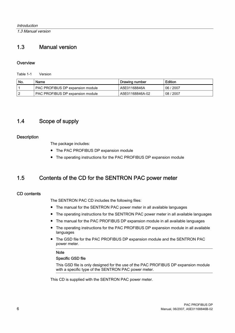
1.3 Manual version
Overview
Table 1-1 Version
No. Name Drawing number Edition 1 PAC PROFIBUS DP expansion module A5E01168846A 06 / 2007 2 PAC PROFIBUS DP expansion module A5E01168846A-02 08 / 2007
1.4 Scope of supply
Description The package includes: ● The PAC PROFIBUS DP expansion module ● The operating instructions for the PAC PROFIBUS DP expansion module
1.5 Contents of the CD for the SENTRON PAC power meter
CD contents The SENTRON PAC CD includes the following files: ● The manual for the SENTRON PAC power meter in all available languages ● The operating instructions for the SENTRON PAC power meter in all available languages ● The manual for the PAC PROFIBUS DP expansion module in all available languages ● The operating instructions for the PAC PROFIBUS DP expansion module in all available
languages ● The GSD file for the PAC PROFIBUS DP expansion module and the SENTRON PAC
power meter.
Note Specific GSD file This GSD file is only designed for the use of the PAC PROFIBUS DP expansion module with a specific type of the SENTRON PAC power meter.
This CD is supplied with the SENTRON PAC power meter.
Introduction 1.6 Technical support
PAC PROFIBUS DP Manual, 06/2007, A5E01168846B-02 7
1.6 Technical support
Contact for technical problems and other questions Help is available from: ● Service and support contacts in your region - worldwide ● Online service and support ● Technical support
Contacts in the region Contacts in your region can provide support worldwide.
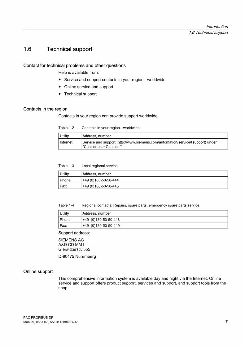
Table 1-2 Contacts in your region - worldwide
Utility Address, number Internet: Service and support (http://www.siemens.com/automation/service&support) under
"Contact us > Contacts"
Table 1-3 Local regional service
Utility Address, number Phone: +49 (0)180-50-50-444 Fax: +49 (0)180-50-50-445
Table 1-4 Regional contacts: Repairs, spare parts, emergency spare parts service
Utility Address, number Phone: +49 (0)180-50-50-448 Fax: +49 (0)180-50-50-449
Support address: SIEMENS AG A&D CD MM1 Gleiwitzerstr. 555 D-90475 Nuremberg
Online support This comprehensive information system is available day and night via the Internet. Online service and support offers product support, services and support, and support tools from the shop.
Introduction 1.7 Further documentation
PAC PROFIBUS DP 8 Manual, 06/2007, A5E01168846B-02
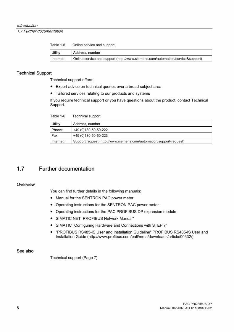
Table 1-5 Online service and support
Utility Address, number Internet: Online service and support (http://www.siemens.com/automation/service&support)
Technical Support Technical support offers: ● Expert advice on technical queries over a broad subject area ● Tailored services relating to our products and systems If you require technical support or you have questions about the product, contact Technical Support.
Table 1-6 Technical support
Utility Address, number Phone: +49 (0)180-50-50-222 Fax: +49 (0)180-50-50-223 Internet: Support request (http://www.siemens.com/automation/support-request)
1.7 Further documentation
Overview You can find further details in the following manuals: ● Manual for the SENTRON PAC power meter ● Operating instructions for the SENTRON PAC power meter ● Operating instructions for the PAC PROFIBUS DP expansion module ● SIMATIC NET PROFIBUS Network Manual" ● SIMATIC "Configuring Hardware and Connections with STEP 7" ● "PROFIBUS RS485-IS User and Installation Guideline" PROFIBUS RS485-IS User and
Installation Guide (http://www.profibus.com/pall/meta/downloads/article/00332/)
See also Technical support (Page 7)
PAC PROFIBUS DP Manual, 06/2007, A5E01168846B-02 9
Safety instructions 22.1 Safety instructions
General safety notes
WARNING
Danger! High voltage During operation of the SENTRON PAC power meter, certain parts of the device are at hazardous voltage levels. If you do not follow the safety information provided on the device, in the operating instructions, and in the manual, this could result in death, serious injury and severe damage to property. Always observe the following five safety rules when installing and carrying out all other tasks: • Disconnect the system • Protect against reconnection. • Make sure the equipment is de-energized. • Ground and short-circuit. • Cover or enclose adjacent components that are still live
CAUTION Short-circuits can cause damage to the power supply A short-circuit can destroy the power supply to the SENTRON PAC power meter. Avoid short-circuits.

Safety instructions 2.1 Safety instructions
PAC PROFIBUS DP 10 Manual, 06/2007, A5E01168846B-02
PAC PROFIBUS DP Manual, 06/2007, A5E01168846B-02 11
Description 33.1 Area of application
The PAC PROFIBUS DP expansion module is designed for use with a SENTRON PAC power meter.
Area of application of the PAC PROFIBUS DP expansion module The PAC PROFIBUS DP expansion module connects the SENTRON PAC power meter to the PROFIBUS network. This integrates the SENTRON PAC power meter into power management systems and automation systems. The PAC PROFIBUS DP expansion module therefore has to communicate with the SENTRON PAC power meter and the PROFIBUS DP master.
NOTICE Intended use of the PAC PROFIBUS DP expansion module The PAC PROFIBUS DP expansion module is only intended for use with a SENTRON PAC power meter. The guidelines for the SENTRON PAC power meter also apply to the PAC PROFIBUS DP expansion module.
3.2 Features You can use the PAC PROFIBUS DP expansion module to access the measuring stations during operation.
Description 3.3 Tasks
PAC PROFIBUS DP 12 Manual, 06/2007, A5E01168846B-02
Overview Features include: ● Communication based on the master-slave principle ● Function: PROFIBUS DP slave ● Configuration via class 1 master ● Cyclic data transfer ● Separate GSD file for power meter, e.g., SENTRON PAC3200. This ensures correct
project planning. ● Automatic baud rate detection ● Watchdog function
The PROFIBUS DP slave uses the watchdog function to monitor data traffic to ensure that the PROFIBUS DP master is enabled and that data are being transferred.
3.3 Tasks
Description The tasks of the PAC PROFIBUS DP expansion module are as follows: ● To supply values measured by the SENTRON PAC power meter to the PROFIBUS DP
master ● To receive information, e.g., commands, from the PROFIBUS DP master and send them
to the SENTRON PAC power meter. ● To ensure galvanic isolation between the SENTRON PAC power meter and the
PROFIBUS
Description 3.4 Structure
PAC PROFIBUS DP Manual, 06/2007, A5E01168846B-02 13
3.4 Structure
Structure of the PAC PROFIBUS DP expansion module
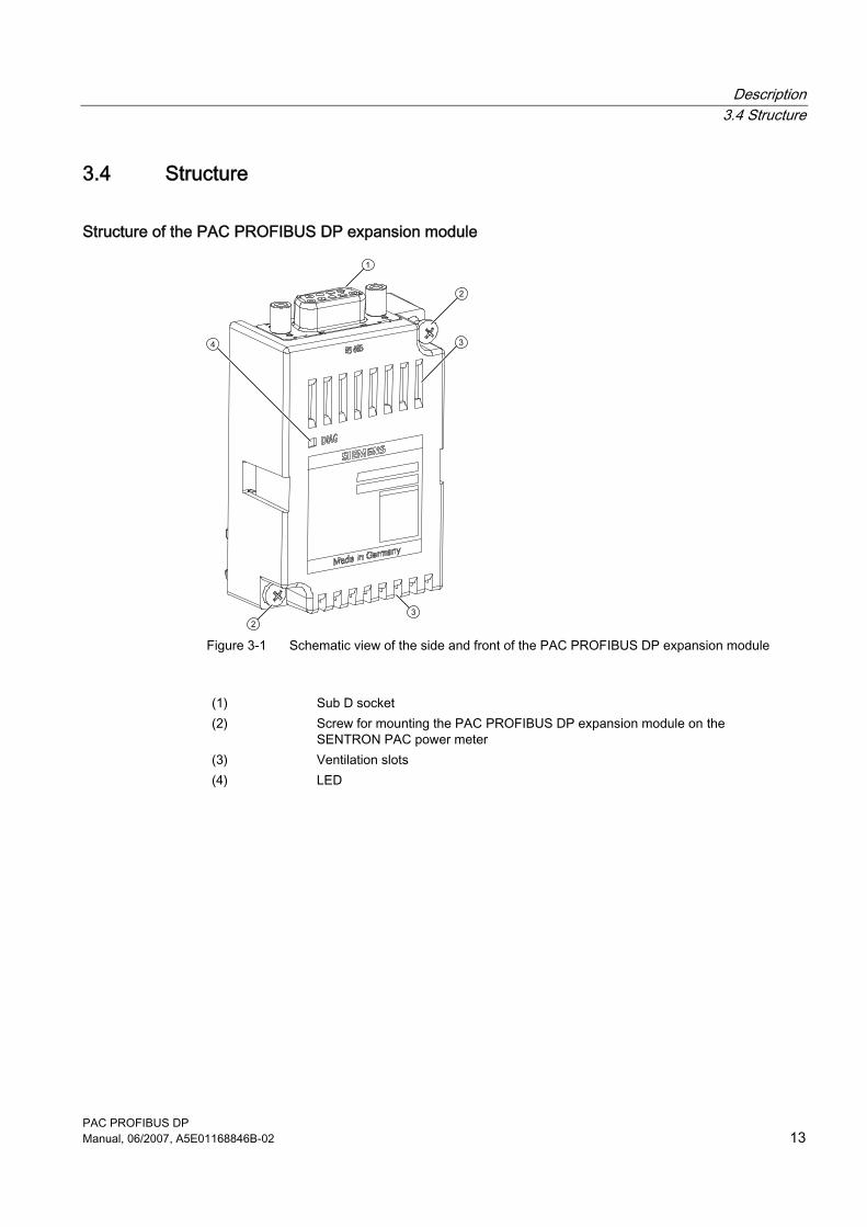
Figure 3-1 Schematic view of the side and front of the PAC PROFIBUS DP expansion module
(1) Sub D socket (2) Screw for mounting the PAC PROFIBUS DP expansion module on the
SENTRON PAC power meter (3) Ventilation slots (4) LED
Description 3.5 PROFIBUS functions
PAC PROFIBUS DP 14 Manual, 06/2007, A5E01168846B-02
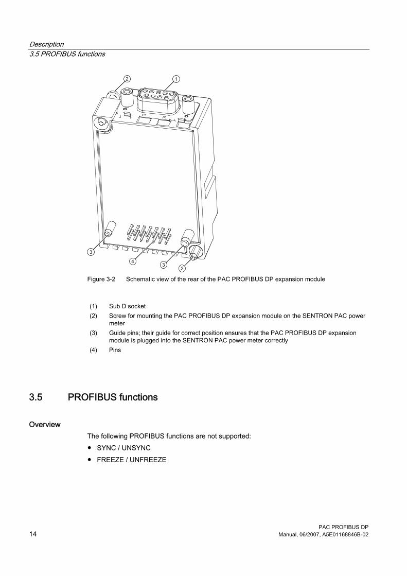
Figure 3-2 Schematic view of the rear of the PAC PROFIBUS DP expansion module
(1) Sub D socket (2) Screw for mounting the PAC PROFIBUS DP expansion module on the SENTRON PAC power
meter (3) Guide pins; their guide for correct position ensures that the PAC PROFIBUS DP expansion
module is plugged into the SENTRON PAC power meter correctly (4) Pins
3.5 PROFIBUS functions
Overview The following PROFIBUS functions are not supported: ● SYNC / UNSYNC ● FREEZE / UNFREEZE
PAC PROFIBUS DP Manual, 06/2007, A5E01168846B-02 15
Installation 44.1 Procedure for installation and commissioning
The following system configuration information must be available: ● Installation location of the device ● Baud rate ● Planned PROFIBUS address
Procedure 1. Mount the SENTRON PAC poewr meter and the PAC PROFIBUS DP expansion module. 2. Connect the SENTRON PAC power meter. 3. Connect the PAC PROFIBUS DP expansion module to the PROFIBUS network. 4. Set the language on the SENTRON PAC power meter. 5. Parameterize the SENTRON PAC power meter. 6. Set the planned PROFIBUS address on the SENTRON PAC power meter. 7. Configure the PAC PROFIBUS DP expansion module. The STEP 7 hardware
configuration, for example, can be used as the configuring tool. – Assign the SENTRON PAC power meter to the PROFIBUS network. – Link the device-specific GSD file for the PAC PROFIBUS DP expansion module. – Parameterize the SENTRON PAC power meter. – Transfer the parameter assignment to the PROFIBUS DP master.
8. Check all connections and settings. 9. Apply supply voltage to the SENTRON PAC power meter. The SENTRON PAC power
meter and expansion module are then ready for operation.
Installation 4.2 Unpacking
PAC PROFIBUS DP 16 Manual, 06/2007, A5E01168846B-02
See also Unpacking (Page 16) Installation and connection (Page 17) Equipotential bonding (Page 20) Measures to be performed prior to start-up (Page 21) Cyclic data exchange (Page 23) Default settings (Page 37) Configuration scenarios (Page 37) Changing the address (Page 38) Configuring by means of the GSD file (Page 39) Contents of the CD for the SENTRON PAC power meter (Page 6)
4.2 Unpacking Observe the ESD guidelines. Open the packaging with care. Do not use excessive force.
Checks After receiving the module, and before installing it, you should make the following checks: ● Check the packaging for damage. ● Make sure that the package contents are complete. ● Check the module for external damage. Please contact your Siemens sales partner in the following cases: ● The packaging is damaged ● The contents of the package are not complete ● The module is damaged
Storage Store the PAC PROFIBUS DP expansion module in a dry place.
See also Electrostatic sensitive devices (ESD) (Page 73)
Installation 4.3 Installation and connection
PAC PROFIBUS DP Manual, 06/2007, A5E01168846B-02 17
4.3 Installation and connection
NOTICE Avoid condensation Sudden fluctuations in temperature can lead to condensation. Condensation can affect the function of the PAC PROFIBUS DP expansion module. Store the PAC PROFIBUS DP expansion module in the operating room for at least 2 hours before commencing installation.
Tools To install the PAC PROFIBUS DP expansion module you will need the following tool: ● A Z1 cross-tip screwdriver, 2.9 mm, cal ISO 6789
Assembly Install the PAC PROFIBUS DP expansion module before operating the SENTRON PAC. Observe the ESD guidelines.
CAUTION Faulty sub D connector and faulty connector to the SENTRON PAC power meter Dirty or bent pins can affect the function of the connectors. The connectors can be destroyed. Do not allow the pins to become dirty. Make sure that: • There are no metal parts between the pins. • There are no metal parts adhering to the pins. • The pins do not bend. Do not touch the pins.
NOTICE Danger of overheating If the ventilation slots are covered, the PAC PROFIBUS DP expansion module can overheat. Make sure that the ventilation slots are not covered.
Installation 4.3 Installation and connection
PAC PROFIBUS DP 18 Manual, 06/2007, A5E01168846B-02
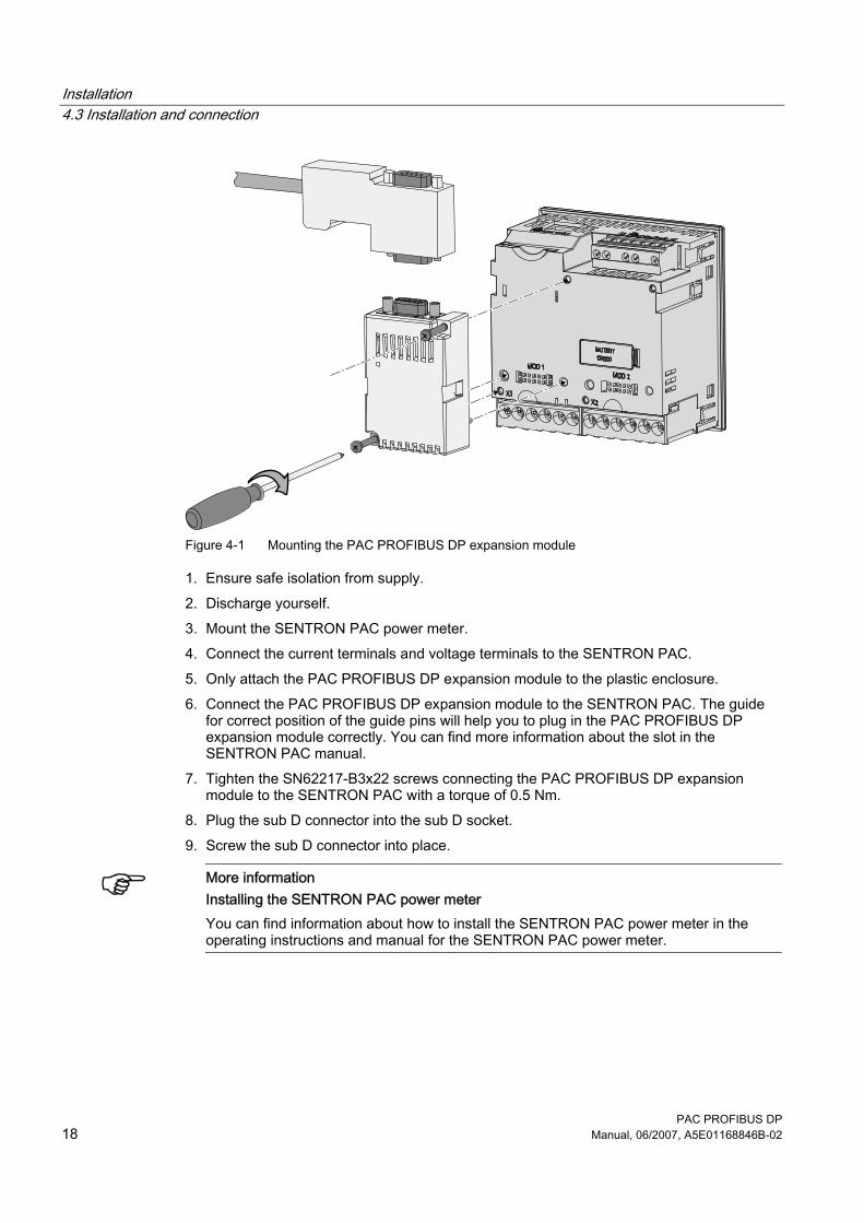
Figure 4-1 Mounting the PAC PROFIBUS DP expansion module
1. Ensure safe isolation from supply. 2. Discharge yourself. 3. Mount the SENTRON PAC power meter. 4. Connect the current terminals and voltage terminals to the SENTRON PAC. 5. Only attach the PAC PROFIBUS DP expansion module to the plastic enclosure. 6. Connect the PAC PROFIBUS DP expansion module to the SENTRON PAC. The guide
for correct position of the guide pins will help you to plug in the PAC PROFIBUS DP expansion module correctly. You can find more information about the slot in the SENTRON PAC manual.
7. Tighten the SN62217-B3x22 screws connecting the PAC PROFIBUS DP expansion module to the SENTRON PAC with a torque of 0.5 Nm.
8. Plug the sub D connector into the sub D socket. 9. Screw the sub D connector into place.
More information
Installing the SENTRON PAC power meter You can find information about how to install the SENTRON PAC power meter in the operating instructions and manual for the SENTRON PAC power meter.
Installation 4.3 Installation and connection
PAC PROFIBUS DP Manual, 06/2007, A5E01168846B-02 19
NOTICE
Damage due to moisture Moisture or wetness can affect the operating capability of the PAC PROFIBUS DP expansion module. Make sure that no moisture or wetness can find its way into the PAC PROFIBUS DP expansion module. Clean the PAC PROFIBUS DP expansion module using a dry, lint-free cloth only. Do not operate the PAC PROFIBUS DP expansion module in an environment affected by high humidity or wetness. Note the environmental requirements of the SENTRON PAC power meter.
Bus termination
Note Bus terminating resistor There is no bus terminating resistor in the PAC PROFIBUS DP expansion module. Bus termination is provided by the PROFIBUS adaptor plug, which includes a bus terminating resistor. You can find more information in the operating instructions for the PROFIBUS adaptor plug.
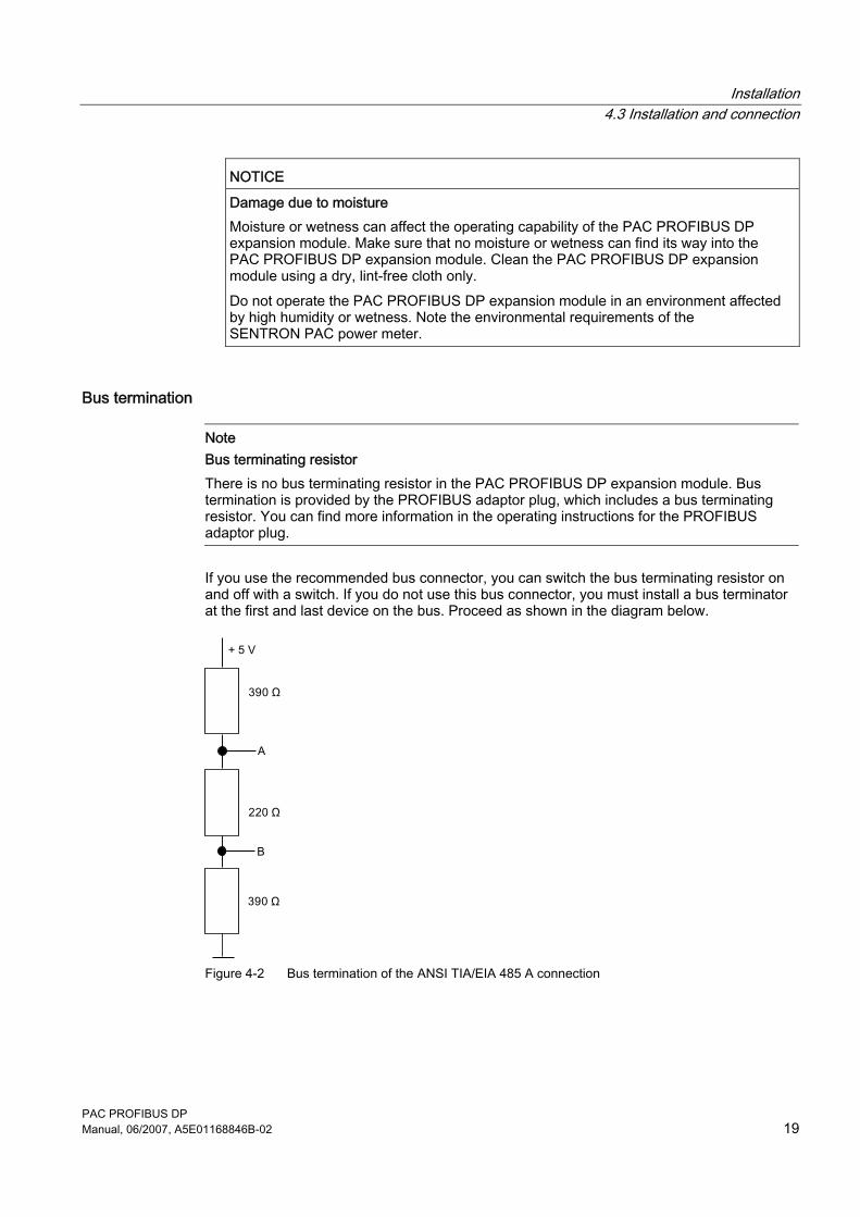
If you use the recommended bus connector, you can switch the bus terminating resistor on and off with a switch. If you do not use this bus connector, you must install a bus terminator at the first and last device on the bus. Proceed as shown in the diagram below.
Figure 4-2 Bus termination of the ANSI TIA/EIA 485 A connection
Installation 4.4 Equipotential bonding
PAC PROFIBUS DP 20 Manual, 06/2007, A5E01168846B-02
More information Bus connectors and PROFIBUS cables You can find information about the bus connector and PROFIBUS cables, etc., in the catalog. The cable length depends on the baud rate. At 12 Mbps the maximum type A cable length is 100 m. You can find more information about cable lengths for PROFIBUS communication in section 22.1 of the standard IEC 61158-2:2004.
See also Disassembly (Page 21) Safety instructions (Page 9) Electrostatic sensitive devices (ESD) (Page 73) Unpacking (Page 16) Measures to be performed prior to start-up (Page 21)
4.4 Equipotential bonding
Equipotential bonding of the PAC PROFIBUS DP expansion module The PAC PROFIBUS DP expansion module has a non-metal housing. You should therefore carry out the equipotential bonding of the PAC PROFIBUS DP expansion module in accordance with the PROFIBUS installation guidelines.
For further information Refer to the "SIMATIC NET PROFIBUS Network Manual".
See also Further documentation (Page 8)
Installation 4.5 Measures to be performed prior to start-up
PAC PROFIBUS DP Manual, 06/2007, A5E01168846B-02 21
4.5 Measures to be performed prior to start-up
CAUTION Impairment and endangering of operation Damaged components can impair and endanger operation. Never use damaged components.
NOTICE Formation of condensation Store the device in the service room for at least two hours before applying voltage to the device for the first time. This will equalize the temperature and prevent the formation of condensation.
Checks Once you have correctly installed the PAC PROFIBUS DP expansion module, you should carry out the following checks: 1. Check that the PAC PROFIBUS DP expansion module is connected to the
SENTRON PAC power meter correctly. 2. Check that the connector of the PROFIBUS cable is plugged into the sub D socket of the
PAC PROFIBUS DP expansion module correctly and screwed down tightly. 3. Check that the ventilation slots are not covered.
4.6 Disassembly
Disassembling 1. Ensure safe isolation from supply. 2. Observe the ESD Guidelines. Discharge yourself. Only attach the PAC PROFIBUS DP
expansion module to the plastic enclosure. 3. Unfasten the screws securing the sub D connector into the sub D socket. 4. Pull the sub D connector out of the sub D socket. 5. Unscrew the PAC PROFIBUS DP expansion module from the SENTRON PAC power
meter. 6. Remove the PAC PROFIBUS DP expansion module from the SENTRON PAC power
meter. 7. If necessary, disassemble the SENTRON PAC power meter.
Installation 4.6 Disassembly
PAC PROFIBUS DP 22 Manual, 06/2007, A5E01168846B-02
More information
Disassembling the SENTRON PAC power meter You can find information about how to disassemble the SENTRON PAC power meter in the manual for the SENTRON PAC power meter.
See also Installation and connection (Page 17) Electrostatic sensitive devices (ESD) (Page 73) Technical support (Page 7) Further documentation (Page 8)
PAC PROFIBUS DP Manual, 06/2007, A5E01168846B-02 23
Parameter assignment/Addressing 55.1 Cyclic data exchange
5.1.1 Introduction
Description In cyclic data exchange, each message frame transfers a fixed number of user data. Cyclic data exchange is especially suitable for transferring information that is required continuously and quickly. The time interval between two message frames depends on: ● The number of nodes ● The data volume ● The baud rate All available data types that PROFIBUS can transfer are defined in the GSD file for the associated SENTRON PAC power meter. For time-saving commissioning and efficient data transfer, there are two basic types with predefined measured variables. The user can also define individual measured variables to be transferred.
Choosing the basic type You can configure each SENTRON PAC power meter individually. During the configuration process you use the PROFIBUS DP configuring tool to select: ● The GSD file ● A suitable combination of basic type 1, basic type 2 and measured variables
Note Note the quantity structure The maximum quantity structure for PROFIBUS is 244 bytes.
See also Measured variables (Page 29) Standards (Page 61) Further documentation (Page 8)
Parameter assignment/Addressing 5.1 Cyclic data exchange
PAC PROFIBUS DP 24 Manual, 06/2007, A5E01168846B-02
5.1.2 Basic type 1
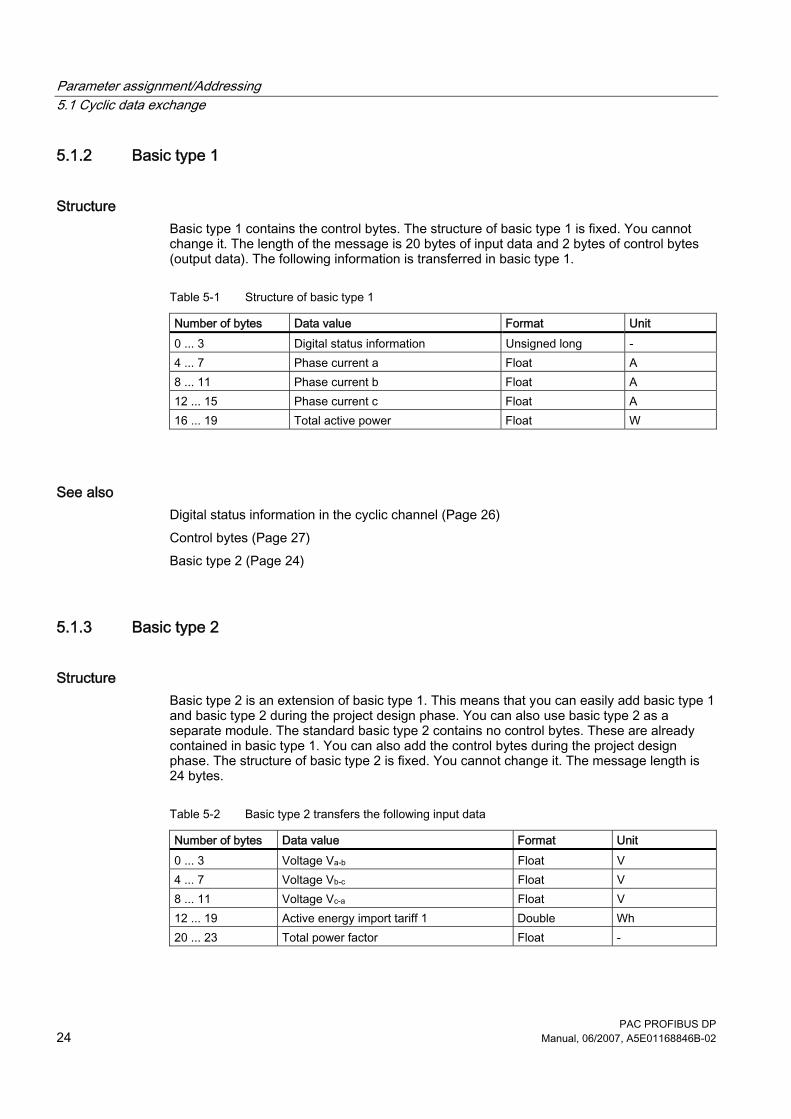
Structure Basic type 1 contains the control bytes. The structure of basic type 1 is fixed. You cannot change it. The length of the message is 20 bytes of input data and 2 bytes of control bytes (output data). The following information is transferred in basic type 1.
Table 5-1 Structure of basic type 1
Number of bytes Data value Format Unit 0 ... 3 Digital status information Unsigned long - 4 ... 7 Phase current a Float A 8 ... 11 Phase current b Float A 12 ... 15 Phase current c Float A 16 ... 19 Total active power Float W
See also Digital status information in the cyclic channel (Page 26) Control bytes (Page 27) Basic type 2 (Page 24)
5.1.3 Basic type 2
Structure Basic type 2 is an extension of basic type 1. This means that you can easily add basic type 1 and basic type 2 during the project design phase. You can also use basic type 2 as a separate module. The standard basic type 2 contains no control bytes. These are already contained in basic type 1. You can also add the control bytes during the project design phase. The structure of basic type 2 is fixed. You cannot change it. The message length is 24 bytes.
Table 5-2 Basic type 2 transfers the following input data
Number of bytes Data value Format Unit 0 ... 3 Voltage Va-b Float V 4 ... 7 Voltage Vb-c Float V 8 ... 11 Voltage Vc-a Float V 12 ... 19 Active energy import tariff 1 Double Wh 20 ... 23 Total power factor Float -
Parameter assignment/Addressing 5.1 Cyclic data exchange
PAC PROFIBUS DP Manual, 06/2007, A5E01168846B-02 25
See also Basic type 1 (Page 24)
5.1.4 Freely definable basic type
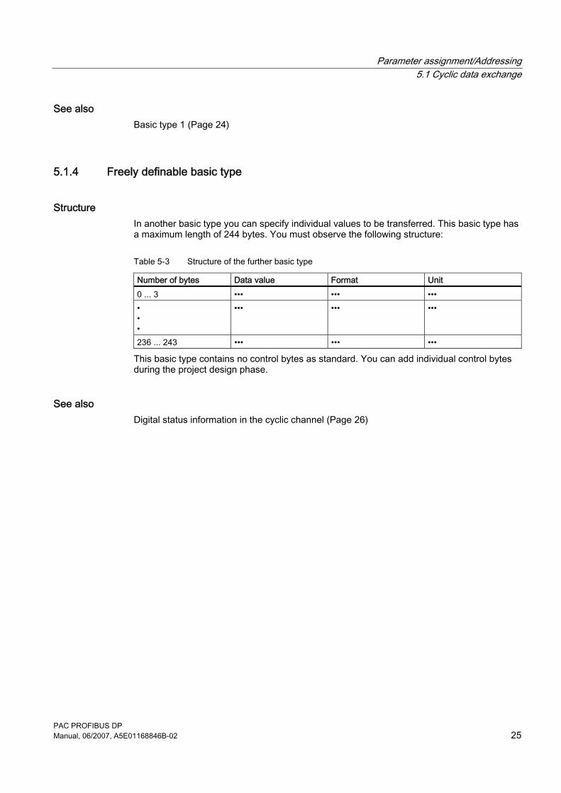
Structure In another basic type you can specify individual values to be transferred. This basic type has a maximum length of 244 bytes. You must observe the following structure:
Table 5-3 Structure of the further basic type
Number of bytes Data value Format Unit 0 ... 3 ••• ••• ••• • • •
••• ••• •••
236 ... 243 ••• ••• •••
This basic type contains no control bytes as standard. You can add individual control bytes during the project design phase.
See also Digital status information in the cyclic channel (Page 26)
Parameter assignment/Addressing 5.1 Cyclic data exchange
PAC PROFIBUS DP 26 Manual, 06/2007, A5E01168846B-02
5.1.5 Digital status information in the cyclic channel
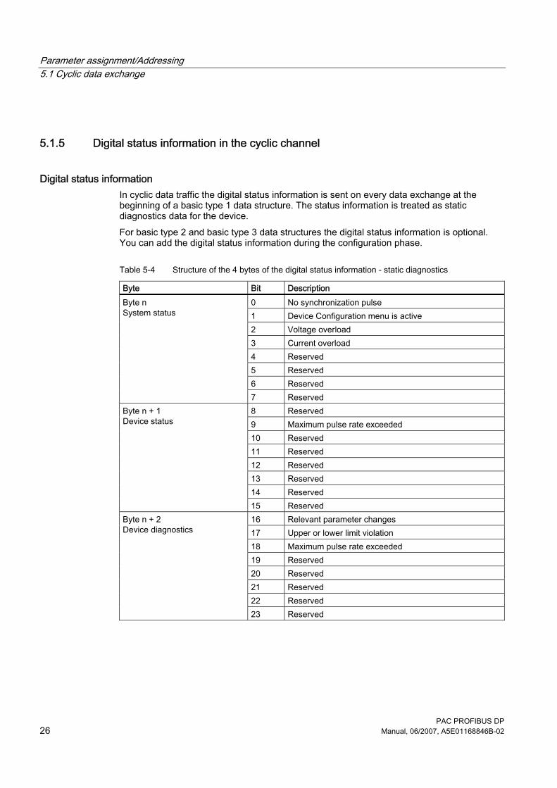
Digital status information In cyclic data traffic the digital status information is sent on every data exchange at the beginning of a basic type 1 data structure. The status information is treated as static diagnostics data for the device. For basic type 2 and basic type 3 data structures the digital status information is optional. You can add the digital status information during the configuration phase.
Table 5-4 Structure of the 4 bytes of the digital status information - static diagnostics
Byte Bit Description 0 No synchronization pulse 1 Device Configuration menu is active 2 Voltage overload 3 Current overload 4 Reserved 5 Reserved 6 Reserved
Byte n System status
7 Reserved 8 Reserved 9 Maximum pulse rate exceeded 10 Reserved 11 Reserved 12 Reserved 13 Reserved 14 Reserved
Byte n + 1 Device status
15 Reserved 16 Relevant parameter changes 17 Upper or lower limit violation 18 Maximum pulse rate exceeded 19 Reserved 20 Reserved 21 Reserved 22 Reserved
Byte n + 2 Device diagnostics
23 Reserved
Parameter assignment/Addressing 5.1 Cyclic data exchange
PAC PROFIBUS DP Manual, 06/2007, A5E01168846B-02 27
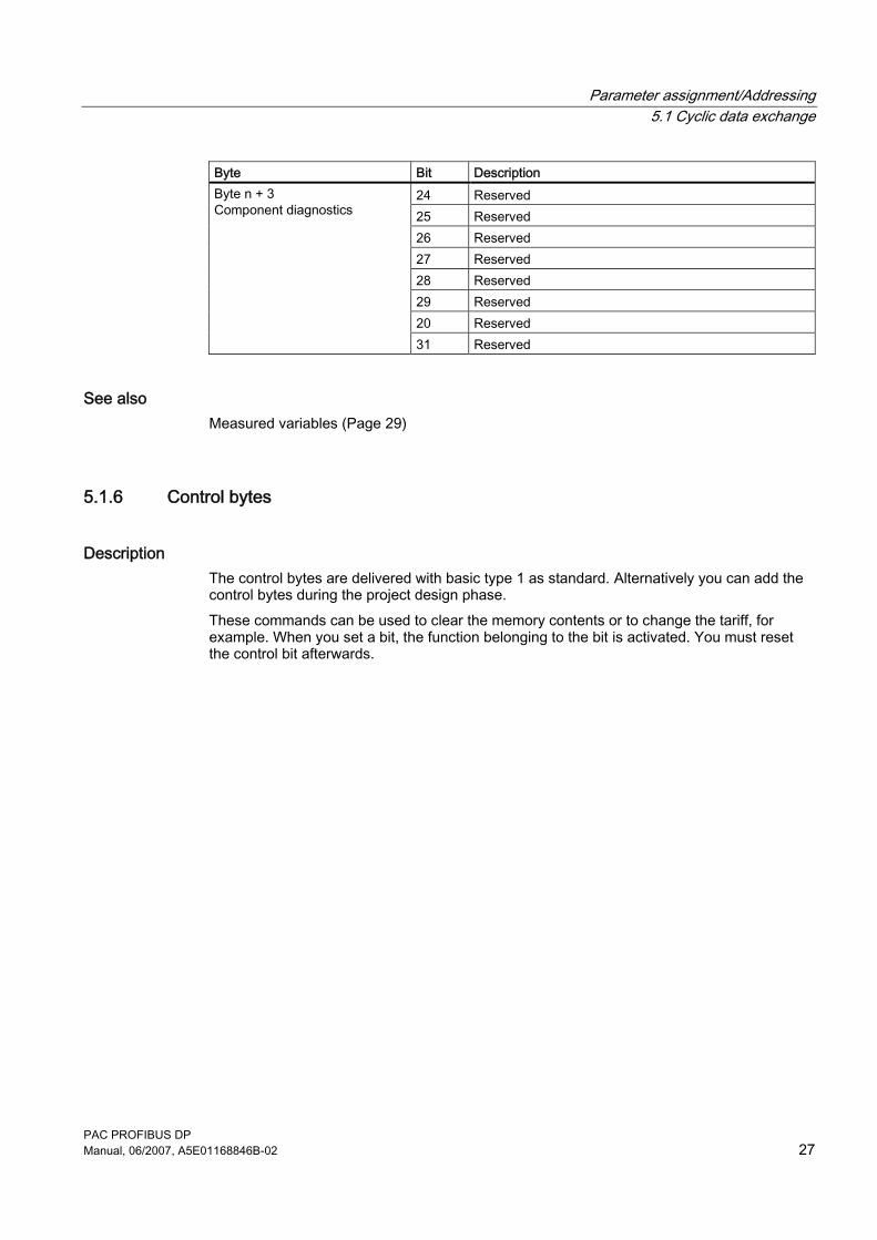
Byte Bit Description 24 Reserved 25 Reserved 26 Reserved 27 Reserved 28 Reserved 29 Reserved 20 Reserved
Byte n + 3 Component diagnostics
31 Reserved
See also Measured variables (Page 29)
5.1.6 Control bytes
Description The control bytes are delivered with basic type 1 as standard. Alternatively you can add the control bytes during the project design phase. These commands can be used to clear the memory contents or to change the tariff, for example. When you set a bit, the function belonging to the bit is activated. You must reset the control bit afterwards.
Parameter assignment/Addressing 5.1 Cyclic data exchange
PAC PROFIBUS DP 28 Manual, 06/2007, A5E01168846B-02
Structure
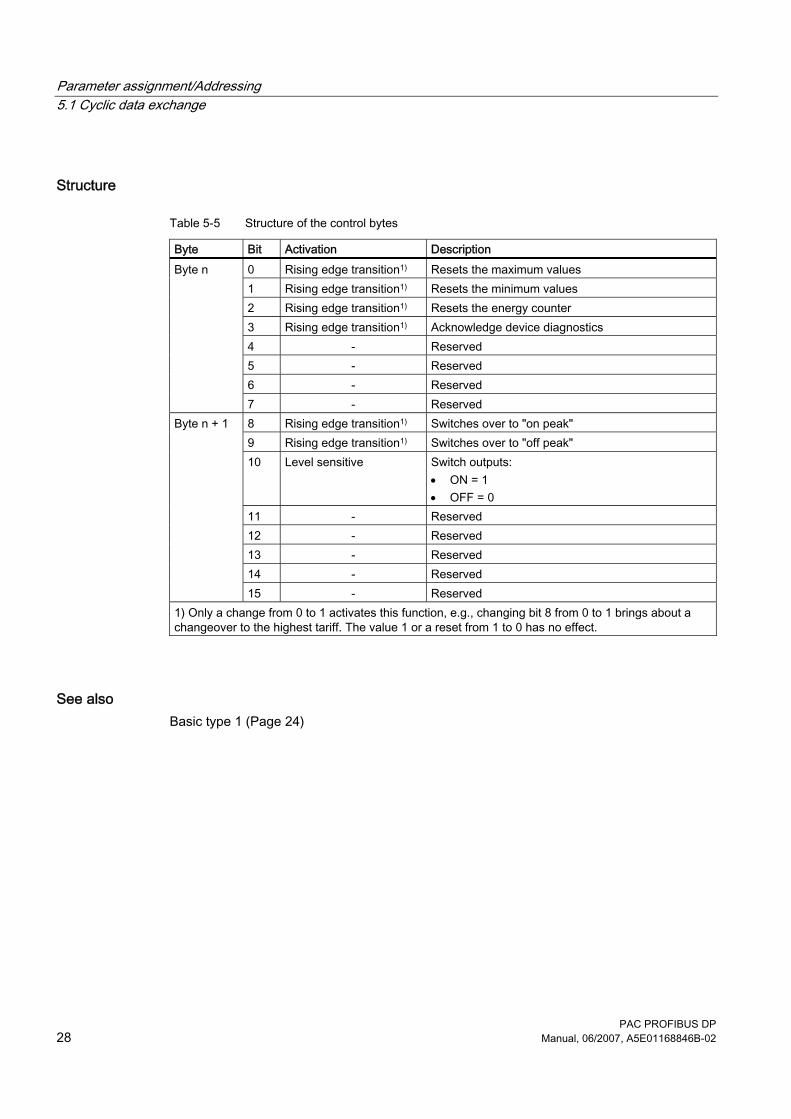
Table 5-5 Structure of the control bytes
Byte Bit Activation Description 0 Rising edge transition1) Resets the maximum values 1 Rising edge transition1) Resets the minimum values 2 Rising edge transition1) Resets the energy counter 3 Rising edge transition1) Acknowledge device diagnostics 4 - Reserved 5 - Reserved 6 - Reserved
Byte n
7 - Reserved 8 Rising edge transition1) Switches over to "on peak" 9 Rising edge transition1) Switches over to "off peak" 10 Level sensitive Switch outputs:
• ON = 1 • OFF = 0
11 - Reserved 12 - Reserved 13 - Reserved 14 - Reserved
Byte n + 1
15 - Reserved 1) Only a change from 0 to 1 activates this function, e.g., changing bit 8 from 0 to 1 brings about a changeover to the highest tariff. The value 1 or a reset from 1 to 0 has no effect.
See also Basic type 1 (Page 24)
Parameter assignment/Addressing 5.1 Cyclic data exchange
PAC PROFIBUS DP Manual, 06/2007, A5E01168846B-02 29
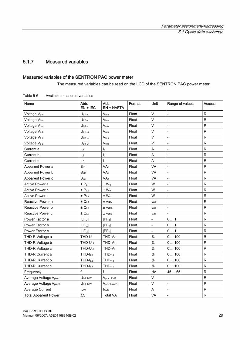
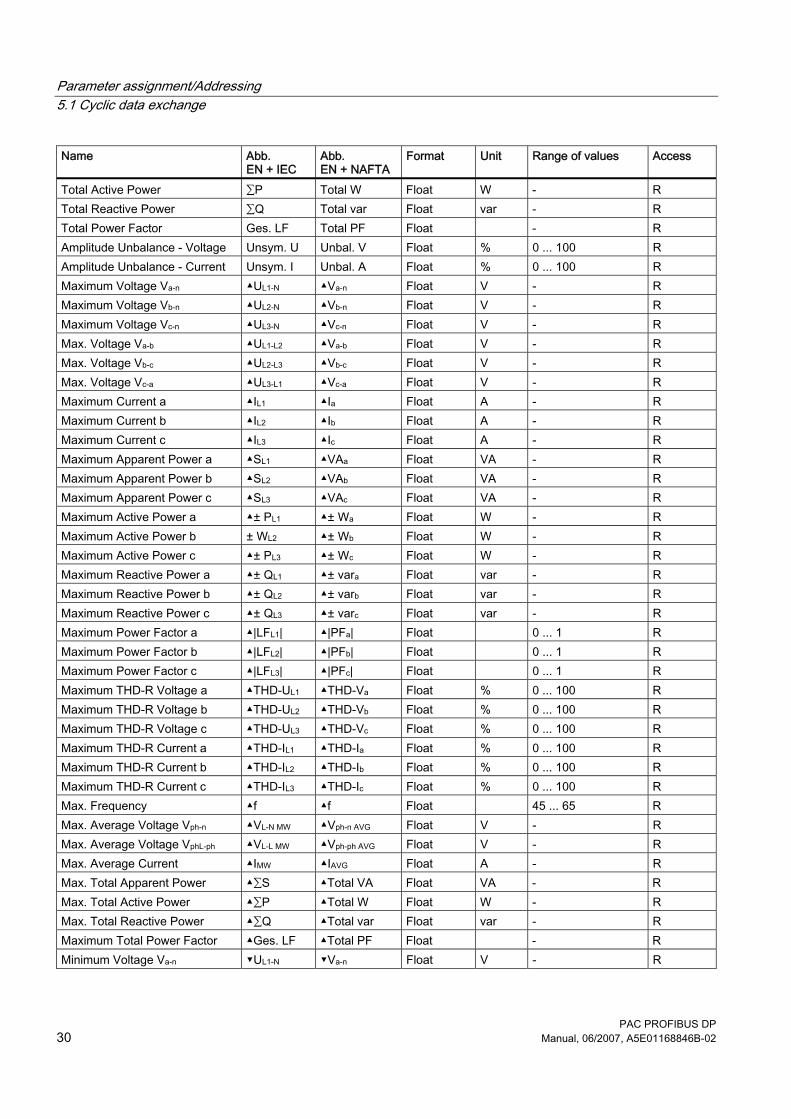
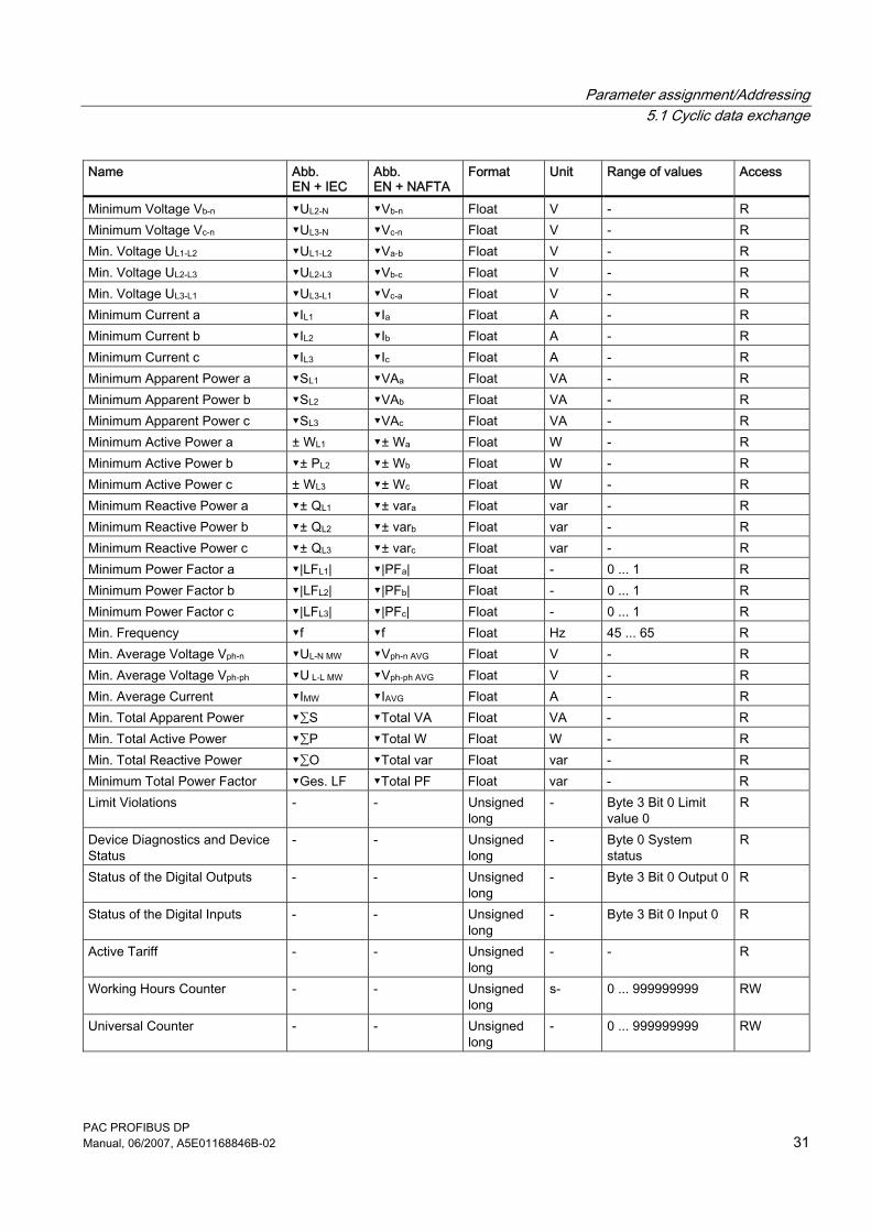
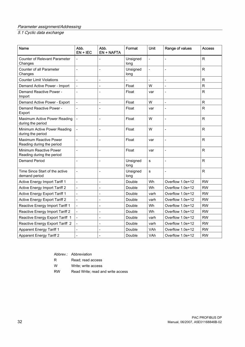
5.1.7 Measured variables
Measured variables of the SENTRON PAC power meter The measured variables can be read on the LCD of the SENTRON PAC power meter.
Table 5-6 Available measured variables
Name Abb. EN + IEC
Abb. EN + NAFTA
Format Unit Range of values Access
Voltage Va-n UL1-N Va-n Float V - R Voltage Vb-n UL2-N Vb-n Float V - R Voltage Vc-n UL3-N Vc-n Float V - R Voltage Va-b UL1-L2 Va-b Float V - R Voltage Vb-c UL2-L3 Vb-c Float V - R Voltage Vc-a UL3-L1 Vc-a Float V - R Current a IL1 Ia Float A - R Current b IL2 Ib Float A - R Current c IL3 Ic Float A - R Apparent Power a SL1 VAa Float VA - R Apparent Power b SL2 VAb Float VA - R Apparent Power c SL3 VAc Float VA - R Active Power a ± PL1 ± Wa Float W - R Active Power b ± PL2 ± Wb Float W - R Active Power c ± PL3 ± Wc Float W - R Reactive Power a ± QL1 ± vara Float var - R Reactive Power b ± QL2 ± varb Float var - R Reactive Power c ± QL3 ± varc Float var - R Power Factor a |LFL1| |PFa| Float - 0 ... 1 R Power Factor b |LFL2| |PFb| Float - 0 ... 1 R Power Factor c |LFL3| |PFc| Float - 0 ... 1 R THD-R Voltage a THD-UL1 THD-Va Float % 0 ... 100 R THD-R Voltage b THD-UL2 THD-Vb Float % 0 ... 100 R THD-R Voltage c THD-UL3 THD-Vc Float % 0 ... 100 R THD-R Current a THD-IL1 THD-Ia Float % 0 ... 100 R THD-R Current b THD-IL2 THD-Ib Float % 0 ... 100 R THD-R Current c THD-IL3 THD-Ic Float % 0 ... 100 R Frequency f f Float Hz 45 ... 65 R Average Voltage Vph-n UL-L MW Vph-n AVG Float V - R Average Voltage Vph-ph UL-L MW Vph-ph AVG Float V - R Average Current IMW IAVG Float A - R Total Apparent Power ∑S Total VA Float VA - R
Parameter assignment/Addressing 5.1 Cyclic data exchange
PAC PROFIBUS DP 30 Manual, 06/2007, A5E01168846B-02
Name Abb. EN + IEC
Abb. EN + NAFTA
Format Unit Range of values Access
Total Active Power ∑P Total W Float W - R Total Reactive Power ∑Q Total var Float var - R Total Power Factor Ges. LF Total PF Float - R Amplitude Unbalance - Voltage Unsym. U Unbal. V Float % 0 ... 100 R Amplitude Unbalance - Current Unsym. I Unbal. A Float % 0 ... 100 R Maximum Voltage Va-n ▲UL1-N ▲Va-n Float V - R Maximum Voltage Vb-n ▲UL2-N ▲Vb-n Float V - R Maximum Voltage Vc-n ▲UL3-N ▲Vc-n Float V - R Max. Voltage Va-b ▲UL1-L2 ▲Va-b Float V - R Max. Voltage Vb-c ▲UL2-L3 ▲Vb-c Float V - R Max. Voltage Vc-a ▲UL3-L1 ▲Vc-a Float V - R Maximum Current a ▲IL1 ▲Ia Float A - R Maximum Current b ▲IL2 ▲Ib Float A - R Maximum Current c ▲IL3 ▲Ic Float A - R Maximum Apparent Power a ▲SL1 ▲VAa Float VA - R Maximum Apparent Power b ▲SL2 ▲VAb Float VA - R Maximum Apparent Power c ▲SL3 ▲VAc Float VA - R Maximum Active Power a ▲± PL1 ▲± Wa Float W - R Maximum Active Power b ± WL2 ▲± Wb Float W - R Maximum Active Power c ▲± PL3 ▲± Wc Float W - R Maximum Reactive Power a ▲± QL1 ▲± vara Float var - R Maximum Reactive Power b ▲± QL2 ▲± varb Float var - R Maximum Reactive Power c ▲± QL3 ▲± varc Float var - R Maximum Power Factor a ▲|LFL1| ▲|PFa| Float 0 ... 1 R Maximum Power Factor b ▲|LFL2| ▲|PFb| Float 0 ... 1 R Maximum Power Factor c ▲|LFL3| ▲|PFc| Float 0 ... 1 R Maximum THD-R Voltage a ▲THD-UL1 ▲THD-Va Float % 0 ... 100 R Maximum THD-R Voltage b ▲THD-UL2 ▲THD-Vb Float % 0 ... 100 R Maximum THD-R Voltage c ▲THD-UL3 ▲THD-Vc Float % 0 ... 100 R Maximum THD-R Current a ▲THD-IL1 ▲THD-Ia Float % 0 ... 100 R Maximum THD-R Current b ▲THD-IL2 ▲THD-Ib Float % 0 ... 100 R Maximum THD-R Current c ▲THD-IL3 ▲THD-Ic Float % 0 ... 100 R Max. Frequency ▲f ▲f Float 45 ... 65 R Max. Average Voltage Vph-n ▲VL-N MW ▲Vph-n AVG Float V - R Max. Average Voltage VphL-ph ▲VL-L MW ▲Vph-ph AVG Float V - R Max. Average Current ▲IMW ▲IAVG Float A - R Max. Total Apparent Power ▲∑S ▲Total VA Float VA - R Max. Total Active Power ▲∑P ▲Total W Float W - R Max. Total Reactive Power ▲∑Q ▲Total var Float var - R Maximum Total Power Factor ▲Ges. LF ▲Total PF Float - R Minimum Voltage Va-n ▼UL1-N ▼Va-n Float V - R
Parameter assignment/Addressing 5.1 Cyclic data exchange
PAC PROFIBUS DP Manual, 06/2007, A5E01168846B-02 31
Name Abb. EN + IEC
Abb. EN + NAFTA
Format Unit Range of values Access
Minimum Voltage Vb-n ▼UL2-N ▼Vb-n Float V - R Minimum Voltage Vc-n ▼UL3-N ▼Vc-n Float V - R Min. Voltage UL1-L2 ▼UL1-L2 ▼Va-b Float V - R Min. Voltage UL2-L3 ▼UL2-L3 ▼Vb-c Float V - R Min. Voltage UL3-L1 ▼UL3-L1 ▼Vc-a Float V - R Minimum Current a ▼IL1 ▼Ia Float A - R Minimum Current b ▼IL2 ▼Ib Float A - R Minimum Current c ▼IL3 ▼Ic Float A - R Minimum Apparent Power a ▼SL1 ▼VAa Float VA - R Minimum Apparent Power b ▼SL2 ▼VAb Float VA - R Minimum Apparent Power c ▼SL3 ▼VAc Float VA - R Minimum Active Power a ± WL1 ▼± Wa Float W - R Minimum Active Power b ▼± PL2 ▼± Wb Float W - R Minimum Active Power c ± WL3 ▼± Wc Float W - R Minimum Reactive Power a ▼± QL1 ▼± vara Float var - R Minimum Reactive Power b ▼± QL2 ▼± varb Float var - R Minimum Reactive Power c ▼± QL3 ▼± varc Float var - R Minimum Power Factor a ▼|LFL1| ▼|PFa| Float - 0 ... 1 R Minimum Power Factor b ▼|LFL2| ▼|PFb| Float - 0 ... 1 R Minimum Power Factor c ▼|LFL3| ▼|PFc| Float - 0 ... 1 R Min. Frequency ▼f ▼f Float Hz 45 ... 65 R Min. Average Voltage Vph-n ▼UL-N MW ▼Vph-n AVG Float V - R Min. Average Voltage Vph-ph ▼U L-L MW ▼Vph-ph AVG Float V - R Min. Average Current ▼IMW ▼IAVG Float A - R Min. Total Apparent Power ▼∑S ▼Total VA Float VA - R Min. Total Active Power ▼∑P ▼Total W Float W - R Min. Total Reactive Power ▼∑O ▼Total var Float var - R Minimum Total Power Factor ▼Ges. LF ▼Total PF Float var - R Limit Violations - - Unsigned
long - Byte 3 Bit 0 Limit
value 0 R
Device Diagnostics and Device Status
- - Unsigned long
- Byte 0 System status
R
Status of the Digital Outputs - - Unsigned long
- Byte 3 Bit 0 Output 0 R
Status of the Digital Inputs - - Unsigned long
- Byte 3 Bit 0 Input 0 R
Active Tariff - - Unsigned long
- - R
Working Hours Counter - - Unsigned long
s- 0 ... 999999999 RW
Universal Counter - - Unsigned long
- 0 ... 999999999 RW
Parameter assignment/Addressing 5.1 Cyclic data exchange
PAC PROFIBUS DP 32 Manual, 06/2007, A5E01168846B-02
Name Abb. EN + IEC
Abb. EN + NAFTA
Format Unit Range of values Access
Counter of Relevant Parameter Changes
- - Unsigned long
- - R
Counter of all Parameter Changes
- - Unsigned long
- - R
Counter Limit Violations - - - - - R Demand Active Power - Import - - Float W - R Demand Reactive Power - Import
- - Float var - R
Demand Active Power - Export - - Float W - R Demand Reactive Power - Export
- - Float var - R
Maximum Active Power Reading during the period
- - Float W - R
Minimum Active Power Reading during the period
- - Float W - R
Maximum Reactive Power Reading during the period
- - Float var - R
Minimum Reactive Power Reading during the period
- - Float var - R
Demand Period - - Unsigned long
s - R
Time Since Start of the active demand period
- - Unsigned long
s - R
Active Energy Import Tariff 1 - - Double Wh Overflow 1.0e+12 RW Active Energy Import Tariff 2 - - Double Wh Overflow 1.0e+12 RW Active Energy Export Tariff 1 - - Double varh Overflow 1.0e+12 RW Active Energy Export Tariff 2 - - Double varh Overflow 1.0e+12 RW Reactive Energy Import Tariff 1 - - Double Wh Overflow 1.0e+12 RW Reactive Energy Import Tariff 2 - - Double Wh Overflow 1.0e+12 RW Reactive Energy Export Tariff 1 - - Double varh Overflow 1.0e+12 RW Reactive Energy Export Tariff 2 - - Double varh Overflow 1.0e+12 RW Apparent Energy Tariff 1 - - Double VAh Overflow 1.0e+12 RW Apparent Energy Tariff 2 - - Double VAh Overflow 1.0e+12 RW
Abbrev.: Abbreviation R Read; read access W Write; write access RW Read Write; read and write access
Parameter assignment/Addressing 5.1 Cyclic data exchange
PAC PROFIBUS DP Manual, 06/2007, A5E01168846B-02 33
See also Introduction (Page 23) Working measured variables in double and float format (Page 33) Configuring by means of the GSD file (Page 39) Limit values (Page 34) Digital status information in the cyclic channel (Page 26) Digital input statuses and output statuses (Page 35)
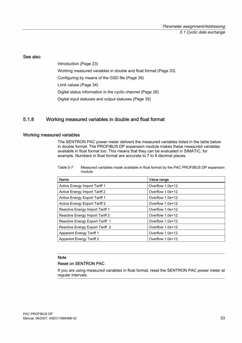
5.1.8 Working measured variables in double and float format
Working measured variables The SENTRON PAC power meter delivers the measured variables listed in the table below in double format. The PROFIBUS DP expansion module makes these measured variables available in float format too. This means that they can be evaluated in SIMATIC, for example. Numbers in float format are accurate to 7 to 8 decimal places.
Table 5-7 Measured variables made available in float format by the PAC PROFIBUS DP expansion module
Name Value range Active Energy Import Tariff 1 Overflow 1.0e+12 Active Energy Import Tariff 2 Overflow 1.0e+12 Active Energy Export Tariff 1 Overflow 1.0e+12 Active Energy Export Tariff 2 Overflow 1.0e+12 Reactive Energy Import Tariff 1 Overflow 1.0e+12 Reactive Energy Import Tariff 2 Overflow 1.0e+12 Reactive Energy Export Tariff 1 Overflow 1.0e+12 Reactive Energy Export Tariff 2 Overflow 1.0e+12 Apparent Energy Tariff 1 Overflow 1.0e+12 Apparent Energy Tariff 2 Overflow 1.0e+12
Note Reset on SENTRON PAC If you are using measured variables in float format, reset the SENTRON PAC power meter at regular intervals.
Parameter assignment/Addressing 5.1 Cyclic data exchange
PAC PROFIBUS DP 34 Manual, 06/2007, A5E01168846B-02
See also Measured variables (Page 29)
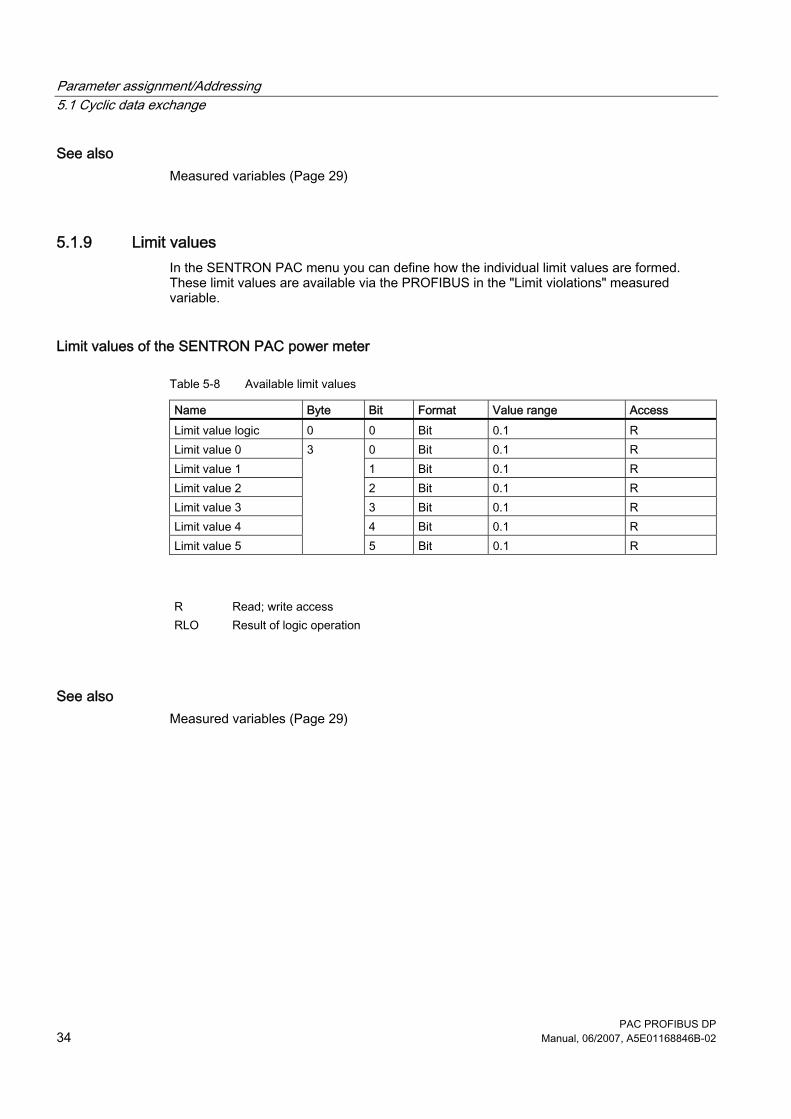
5.1.9 Limit values In the SENTRON PAC menu you can define how the individual limit values are formed. These limit values are available via the PROFIBUS in the "Limit violations" measured variable.
Limit values of the SENTRON PAC power meter
Table 5-8 Available limit values
Name Byte Bit Format Value range Access Limit value logic 0 0 Bit 0.1 R Limit value 0 0 Bit 0.1 R Limit value 1 1 Bit 0.1 R Limit value 2 2 Bit 0.1 R Limit value 3 3 Bit 0.1 R Limit value 4 4 Bit 0.1 R Limit value 5
3
5 Bit 0.1 R
R Read; write access RLO Result of logic operation
See also Measured variables (Page 29)
Parameter assignment/Addressing 5.1 Cyclic data exchange
PAC PROFIBUS DP Manual, 06/2007, A5E01168846B-02 35
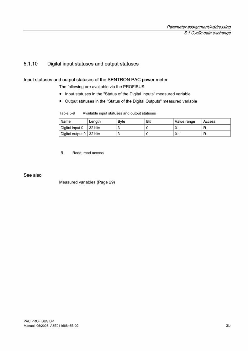
5.1.10 Digital input statuses and output statuses
Input statuses and output statuses of the SENTRON PAC power meter The following are available via the PROFIBUS: ● Input statuses in the "Status of the Digital Inputs" measured variable ● Output statuses in the "Status of the Digital Outputs" measured variable
Table 5-9 Available input statuses and output statuses
Name Length Byte Bit Value range Access Digital input 0 32 bits 3 0 0.1 R Digital output 0 32 bits 3 0 0.1 R
R Read; read access
See also Measured variables (Page 29)

Parameter assignment/Addressing 5.1 Cyclic data exchange
PAC PROFIBUS DP 36 Manual, 06/2007, A5E01168846B-02
PAC PROFIBUS DP Manual, 06/2007, A5E01168846B-02 37
Configuring 66.1 Default settings
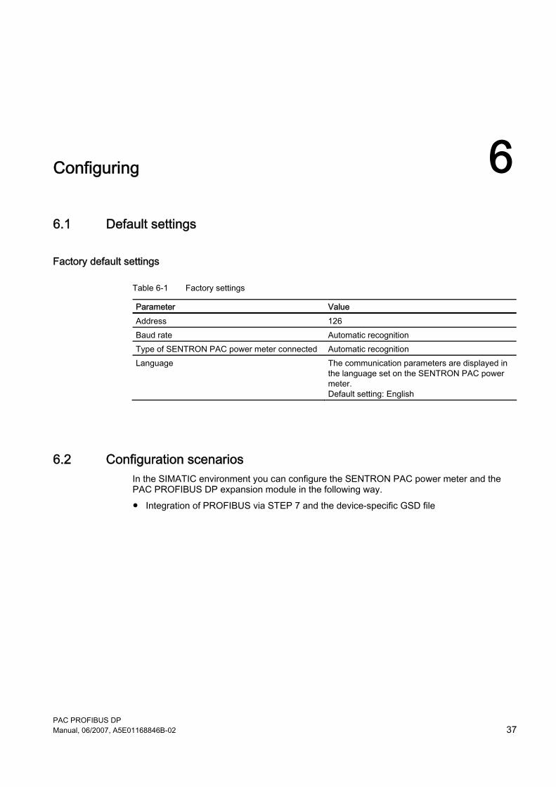
Factory default settings
Table 6-1 Factory settings
Parameter Value Address 126 Baud rate Automatic recognition Type of SENTRON PAC power meter connected Automatic recognition Language The communication parameters are displayed in
the language set on the SENTRON PAC power meter. Default setting: English
6.2 Configuration scenarios In the SIMATIC environment you can configure the SENTRON PAC power meter and the PAC PROFIBUS DP expansion module in the following way. ● Integration of PROFIBUS via STEP 7 and the device-specific GSD file
Configuring 6.3 Changing the address
PAC PROFIBUS DP 38 Manual, 06/2007, A5E01168846B-02
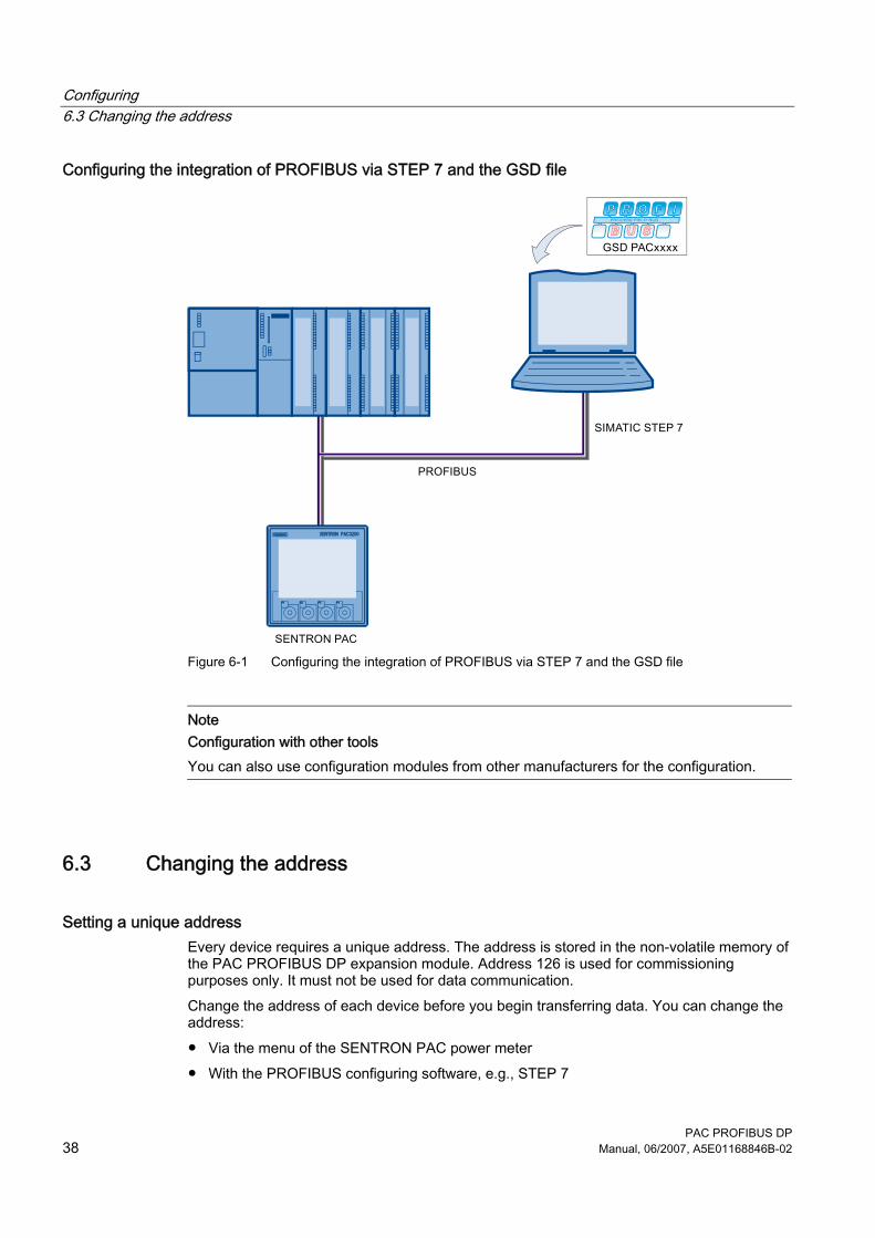
Configuring the integration of PROFIBUS via STEP 7 and the GSD file
Figure 6-1 Configuring the integration of PROFIBUS via STEP 7 and the GSD file
Note Configuration with other tools You can also use configuration modules from other manufacturers for the configuration.
6.3 Changing the address
Setting a unique address Every device requires a unique address. The address is stored in the non-volatile memory of the PAC PROFIBUS DP expansion module. Address 126 is used for commissioning purposes only. It must not be used for data communication. Change the address of each device before you begin transferring data. You can change the address: ● Via the menu of the SENTRON PAC power meter ● With the PROFIBUS configuring software, e.g., STEP 7
Configuring 6.4 Configuring by means of the GSD file
PAC PROFIBUS DP Manual, 06/2007, A5E01168846B-02 39
CAUTION
Address change on device immediately valid When you change the address of the PROFIBUS DP slave on the SENTRON PAC, the new address is accepted as soon as you quit the "Change Address" menu. Reconfigure the PROFIBUS DP master with the new address. Communication is interrupted until this change takes effect.
6.4 Configuring by means of the GSD file
Task of the GSD file The GSD file is a text file in ASCII format. It describes: ● The device features ● The communication characteristics The GSD file makes this data available to the master. The GSD file is the basis for the configuration of a device. PROFIBUS devices have a unique PROFIBUS ID number and a GSD file. The GSD file is matched to the SENTRON PAC power meter. This supports correct project planning and differentiation between devices at a project level.
Language of the GSD file The GSD file is language-dependent.
Table 6-2 GSD file extensions
Language-dependent GSD file extension Language GSE English (ANSI) GSG German GSF French GSI Italian GSP Portuguese GSS Spanish GSD Language-neutral (English IEC)
Configuring 6.4 Configuring by means of the GSD file
PAC PROFIBUS DP 40 Manual, 06/2007, A5E01168846B-02
Configuring by means of the GSD file, based on STEP 7
Table 6-3 Procedure
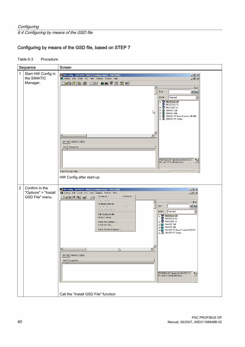
Sequence Screen 1 Start HW Config in
the SIMATIC Manager.
HW Config after start-up
2 Confirm in the "Options" > "Install GSD File" menu.
Call the "Install GSD File" function
Configuring 6.4 Configuring by means of the GSD file
PAC PROFIBUS DP Manual, 06/2007, A5E01168846B-02 41
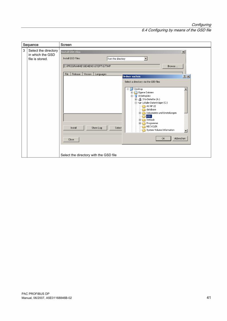
Sequence Screen 3 Select the directory
in which the GSD file is stored.
Select the directory with the GSD file
Configuring 6.4 Configuring by means of the GSD file
PAC PROFIBUS DP 42 Manual, 06/2007, A5E01168846B-02
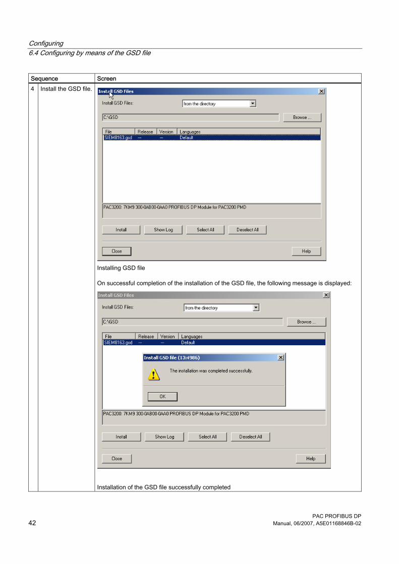
Sequence Screen 4 Install the GSD file.
Installing GSD file
On successful completion of the installation of the GSD file, the following message is displayed:
Installation of the GSD file successfully completed
Configuring 6.4 Configuring by means of the GSD file
PAC PROFIBUS DP Manual, 06/2007, A5E01168846B-02 43
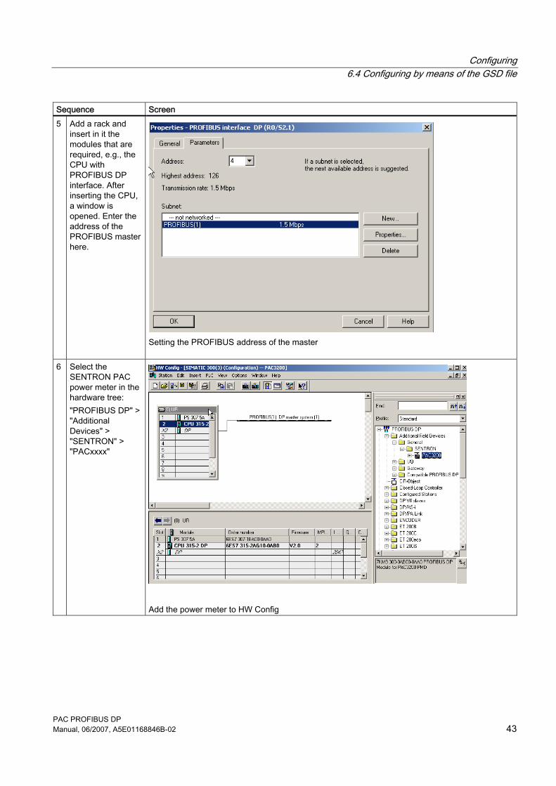
Sequence Screen 5 Add a rack and
insert in it the modules that are required, e.g., the CPU with PROFIBUS DP interface. After inserting the CPU, a window is opened. Enter the address of the PROFIBUS master here.
Setting the PROFIBUS address of the master
6 Select the SENTRON PAC power meter in the hardware tree: "PROFIBUS DP" > "Additional Devices" > "SENTRON" > "PACxxxx"
Add the power meter to HW Config
Configuring 6.4 Configuring by means of the GSD file
PAC PROFIBUS DP 44 Manual, 06/2007, A5E01168846B-02
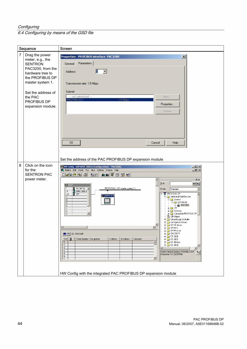
Sequence Screen 7 Drag the power
meter, e.g., the SENTRON PAC3200, from the hardware tree to the PROFIBUS DP master system 1. Set the address of the PAC PROFIBUS DP expansion module.
Set the address of the PAC PROFIBUS DP expansion module
8 Click on the icon for the SENTRON PAC power meter.
HW Config with the integrated PAC PROFIBUS DP expansion module
Configuring 6.4 Configuring by means of the GSD file
PAC PROFIBUS DP Manual, 06/2007, A5E01168846B-02 45
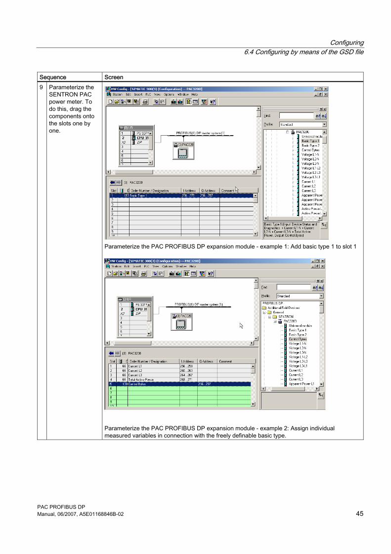
Sequence Screen 9 Parameterize the
SENTRON PAC power meter. To do this, drag the components onto the slots one by one.
Parameterize the PAC PROFIBUS DP expansion module - example 1: Add basic type 1 to slot 1
Parameterize the PAC PROFIBUS DP expansion module - example 2: Assign individual measured variables in connection with the freely definable basic type.
Configuring 6.4 Configuring by means of the GSD file
PAC PROFIBUS DP 46 Manual, 06/2007, A5E01168846B-02
NOTICE Only one set of control bytes There can only be one set of control bytes per device. If you add basic type 1 during the parameterization stage, then you must not add control bytes separately.
NOTICE Do not use the universal module Because of the predefined data types and the available measured values, the use of the STEP 7 universal module in the configuration is not supported.
See also Default settings (Page 37) Contents of the CD for the SENTRON PAC power meter (Page 6) Technical support (Page 7) Measured variables (Page 29)
PAC PROFIBUS DP Manual, 06/2007, A5E01168846B-02 47
Maintenance, service and disposal 77.1 Cleaning
Description The PAC PROFIBUS DP expansion module is maintenance-free.
NOTICE Damage due to detergents Detergents can damage the device. Do not use detergents.
NOTICE Faulty connector Be careful not to bend the pins of the connector. Bent pins can destroy the connector.
1. Use only a dry, lint-free, antistatic cloth to clean the housing. 2. Clean the pins carefully using a brush.
Maintenance, service and disposal 7.2 Repair
PAC PROFIBUS DP 48 Manual, 06/2007, A5E01168846B-02
7.2 Repair
Procedure
CAUTION Loss of certification and warranty If you open the module, the module certification will be lost and the Siemens warranty will be invalidated. Only the manufacturer is permitted to carry out repairs on the module. Return faulty or damaged modules to Siemens for repair or replacement.
If the module is faulty or damaged, proceed as follows: 1. Discharge yourself. 2. Remove the module. 3. Pack the module in a suitable manner to prevent it from being damaged during transport. 4. Return the module to Siemens. You can obtain the address from:
– Your Siemens sales partner – Technical support
See also Electrostatic sensitive devices (ESD) (Page 73) Disassembly (Page 21) Technical support (Page 7)
7.3 Disposal
Disposal and recycling Dispose of or recycle the module in accordance with the applicable laws and regulations in your country.
PAC PROFIBUS DP Manual, 06/2007, A5E01168846B-02 49
Interrupt, error, and system messages 88.1 Diagnostics concept
Diagnostic information The following PROFIBUS DP diagnostic information is available: 1. Slave diagnostics in accordance with standard 2. Enhanced diagnostics
– Device diagnostics
8.2 Slave diagnostics
Structure of the slave diagnostics
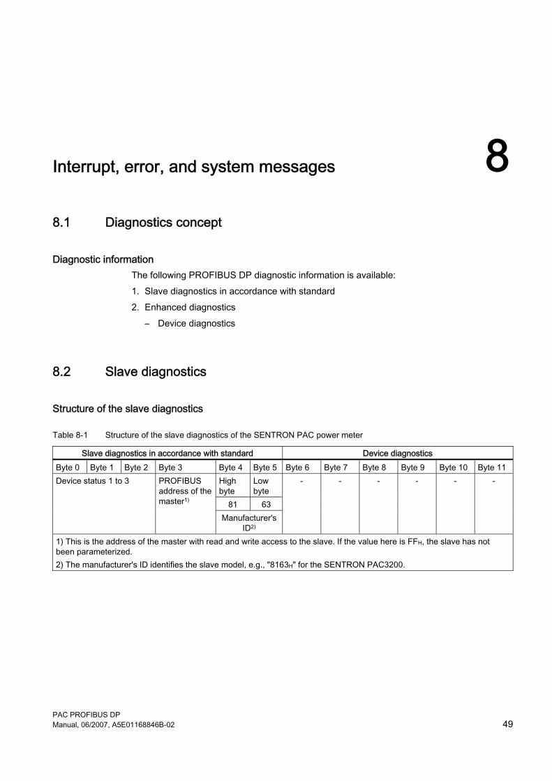
Table 8-1 Structure of the slave diagnostics of the SENTRON PAC power meter
Slave diagnostics in accordance with standard Device diagnostics Byte 0 Byte 1 Byte 2 Byte 3 Byte 4 Byte 5 Byte 6 Byte 7 Byte 8 Byte 9 Byte 10 Byte 11
High byte
Low byte
81 63
Device status 1 to 3 PROFIBUS address of the master1)
Manufacturer's ID2)
- - - - - -
1) This is the address of the master with read and write access to the slave. If the value here is FFH, the slave has not been parameterized. 2) The manufacturer's ID identifies the slave model, e.g., "8163H" for the SENTRON PAC3200.
Interrupt, error, and system messages 8.3 Diagnostics LED
PAC PROFIBUS DP 50 Manual, 06/2007, A5E01168846B-02
8.3 Diagnostics LED
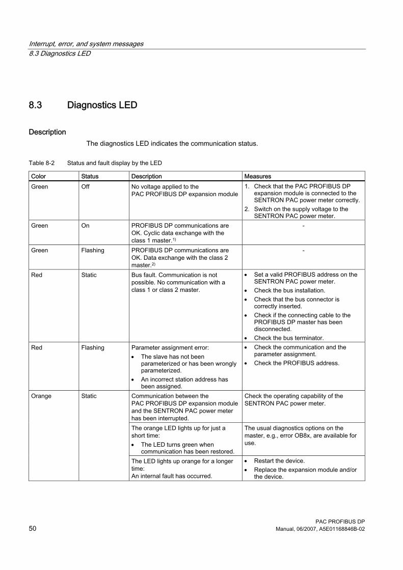
Description The diagnostics LED indicates the communication status.
Table 8-2 Status and fault display by the LED
Color Status Description Measures Green Off No voltage applied to the
PAC PROFIBUS DP expansion module 1. Check that the PAC PROFIBUS DP
expansion module is connected to the SENTRON PAC power meter correctly.
2. Switch on the supply voltage to the SENTRON PAC power meter.
Green On PROFIBUS DP communications are OK. Cyclic data exchange with the class 1 master.1)
-
Green Flashing PROFIBUS DP communications are OK. Data exchange with the class 2 master.2)
-
Red Static Bus fault. Communication is not possible. No communication with a class 1 or class 2 master.
• Set a valid PROFIBUS address on the SENTRON PAC power meter.
• Check the bus installation. • Check that the bus connector is
correctly inserted. • Check if the connecting cable to the
PROFIBUS DP master has been disconnected.
• Check the bus terminator. Red Flashing Parameter assignment error:
• The slave has not been parameterized or has been wrongly parameterized.
• An incorrect station address has been assigned.
• Check the communication and the parameter assignment.
• Check the PROFIBUS address.
Communication between the PAC PROFIBUS DP expansion module and the SENTRON PAC power meter has been interrupted.
Check the operating capability of the SENTRON PAC power meter.
The orange LED lights up for just a short time: • The LED turns green when
communication has been restored.
The usual diagnostics options on the master, e.g., error OB8x, are available for use.
Orange Static
The LED lights up orange for a longer time: An internal fault has occurred.
• Restart the device. • Replace the expansion module and/or
the device.
Interrupt, error, and system messages 8.4 Structure of the device statuses
PAC PROFIBUS DP Manual, 06/2007, A5E01168846B-02 51
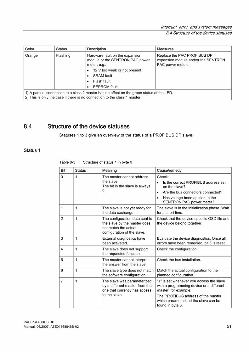
Color Status Description Measures Orange Flashing Hardware fault on the expansion
module or the SENTRON PAC power meter, e.g.: • 12 V too weak or not present • SRAM fault • Flash fault • EEPROM fault
Replace the PAC PROFIBUS DP expansion module and/or the SENTRON PAC power meter.
1) A parallel connection to a class 2 master has no effect on the green status of the LED. 2) This is only the case if there is no connection to the class 1 master.
8.4 Structure of the device statuses Statuses 1 to 3 give an overview of the status of a PROFIBUS DP slave.
Status 1
Table 8-3 Structure of status 1 in byte 0
Bit Status Meaning Cause/remedy 0 1 The master cannot address
the slave. The bit in the slave is always 0.
Check: • Is the correct PROFIBUS address set
on the slave? • Are the bus connectors connected? • Has voltage been applied to the
SENTRON PAC power meter? 1 1 The slave is not yet ready for
the data exchange. The slave is in the initialization phase. Wait for a short time.
2 1 The configuration data sent to the slave by the master does not match the actual configuration of the slave.
Check that the device-specific GSD file and the device belong together.
3 1 External diagnostics have been activated.
Evaluate the device diagnostics. Once all errors have been remedied, bit 3 is reset.
4 1 The slave does not support the requested function.
Check the configuration.
5 1 The master cannot interpret the answer from the slave.
Check the bus installation.
6 1 The slave type does not match the software configuration.
Match the actual configuration to the planned configuration.
7 1 The slave was parameterized by a different master from the one that currently has access to the slave.
"1" is set whenever you access the slave with a programming device or a different master, for example. The PROFIBUS address of the master which parameterized the slave can be found in byte 3.
Interrupt, error, and system messages 8.5 Structure of the device diagnostics
PAC PROFIBUS DP 52 Manual, 06/2007, A5E01168846B-02
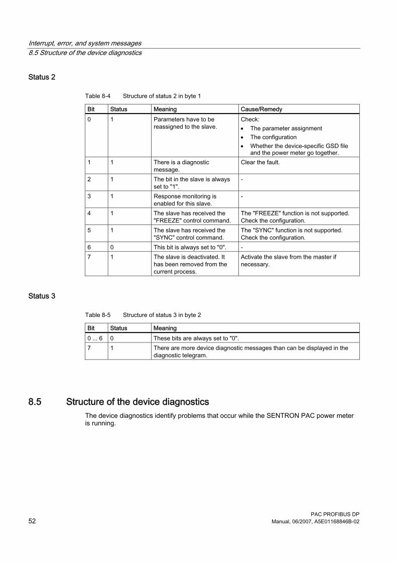
Status 2
Table 8-4 Structure of status 2 in byte 1
Bit Status Meaning Cause/Remedy 0 1 Parameters have to be
reassigned to the slave. Check: • The parameter assignment • The configuration • Whether the device-specific GSD file
and the power meter go together. 1 1 There is a diagnostic
message. Clear the fault.
2 1 The bit in the slave is always set to "1".
-
3 1 Response monitoring is enabled for this slave.
-
4 1 The slave has received the "FREEZE" control command.
The "FREEZE" function is not supported. Check the configuration.
5 1 The slave has received the "SYNC" control command.
The "SYNC" function is not supported. Check the configuration.
6 0 This bit is always set to "0". - 7 1 The slave is deactivated. It
has been removed from the current process.
Activate the slave from the master if necessary.
Status 3
Table 8-5 Structure of status 3 in byte 2
Bit Status Meaning 0 ... 6 0 These bits are always set to "0". 7 1 There are more device diagnostic messages than can be displayed in the
diagnostic telegram.
8.5 Structure of the device diagnostics The device diagnostics identify problems that occur while the SENTRON PAC power meter is running.
Interrupt, error, and system messages 8.5 Structure of the device diagnostics
PAC PROFIBUS DP Manual, 06/2007, A5E01168846B-02 53
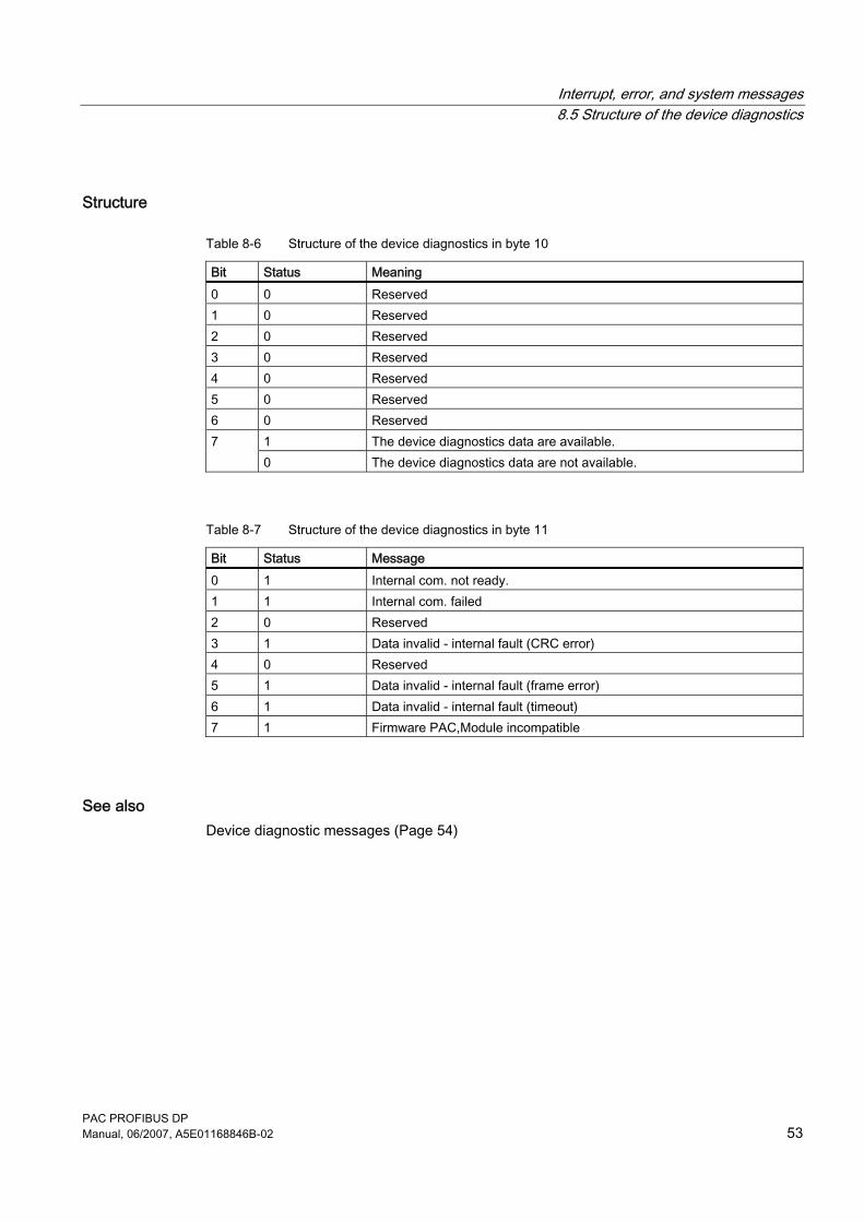
Structure
Table 8-6 Structure of the device diagnostics in byte 10
Bit Status Meaning 0 0 Reserved 1 0 Reserved 2 0 Reserved 3 0 Reserved 4 0 Reserved 5 0 Reserved 6 0 Reserved
1 The device diagnostics data are available. 7 0 The device diagnostics data are not available.
Table 8-7 Structure of the device diagnostics in byte 11
Bit Status Message 0 1 Internal com. not ready. 1 1 Internal com. failed 2 0 Reserved 3 1 Data invalid - internal fault (CRC error) 4 0 Reserved 5 1 Data invalid - internal fault (frame error) 6 1 Data invalid - internal fault (timeout) 7 1 Firmware PAC,Module incompatible
See also Device diagnostic messages (Page 54)
Interrupt, error, and system messages 8.6 Device diagnostic messages
PAC PROFIBUS DP 54 Manual, 06/2007, A5E01168846B-02
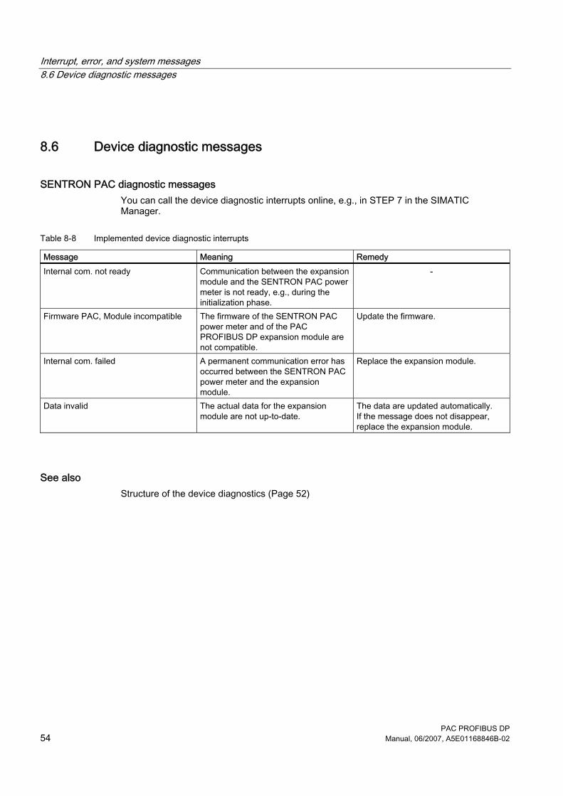
8.6 Device diagnostic messages
SENTRON PAC diagnostic messages You can call the device diagnostic interrupts online, e.g., in STEP 7 in the SIMATIC Manager.
Table 8-8 Implemented device diagnostic interrupts
Message Meaning Remedy Internal com. not ready Communication between the expansion
module and the SENTRON PAC power meter is not ready, e.g., during the initialization phase.
-
Firmware PAC, Module incompatible The firmware of the SENTRON PAC power meter and of the PAC PROFIBUS DP expansion module are not compatible.
Update the firmware.
Internal com. failed A permanent communication error has occurred between the SENTRON PAC power meter and the expansion module.
Replace the expansion module.
Data invalid The actual data for the expansion module are not up-to-date.
The data are updated automatically. If the message does not disappear, replace the expansion module.
See also Structure of the device diagnostics (Page 52)
Interrupt, error, and system messages 8.7 Initializing the module
PAC PROFIBUS DP Manual, 06/2007, A5E01168846B-02 55
8.7 Initializing the module
Starting communication between the PAC PROFIBUS DP expansion module and the SENTRON PAC power meter
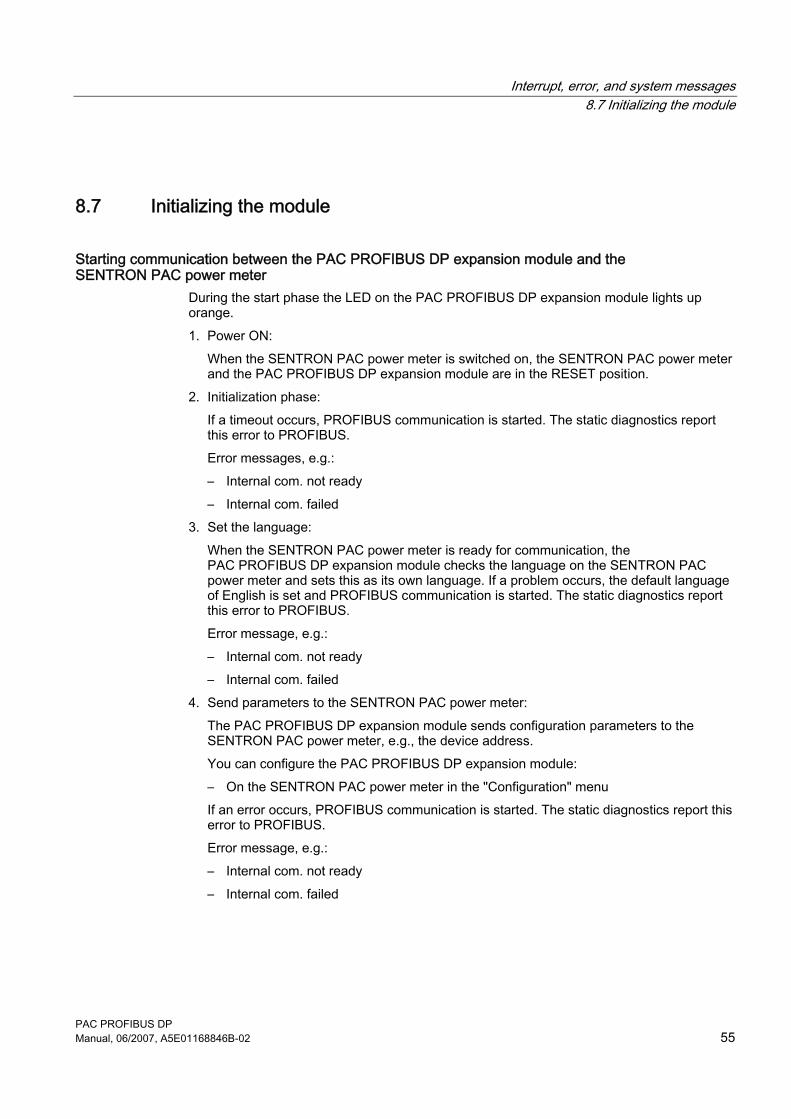
During the start phase the LED on the PAC PROFIBUS DP expansion module lights up orange. 1. Power ON:
When the SENTRON PAC power meter is switched on, the SENTRON PAC power meter and the PAC PROFIBUS DP expansion module are in the RESET position.
2. Initialization phase: If a timeout occurs, PROFIBUS communication is started. The static diagnostics report this error to PROFIBUS. Error messages, e.g.: – Internal com. not ready – Internal com. failed
3. Set the language: When the SENTRON PAC power meter is ready for communication, the PAC PROFIBUS DP expansion module checks the language on the SENTRON PAC power meter and sets this as its own language. If a problem occurs, the default language of English is set and PROFIBUS communication is started. The static diagnostics report this error to PROFIBUS. Error message, e.g.: – Internal com. not ready – Internal com. failed
4. Send parameters to the SENTRON PAC power meter: The PAC PROFIBUS DP expansion module sends configuration parameters to the SENTRON PAC power meter, e.g., the device address. You can configure the PAC PROFIBUS DP expansion module: – On the SENTRON PAC power meter in the "Configuration" menu If an error occurs, PROFIBUS communication is started. The static diagnostics report this error to PROFIBUS. Error message, e.g.: – Internal com. not ready – Internal com. failed
Interrupt, error, and system messages 8.7 Initializing the module
PAC PROFIBUS DP 56 Manual, 06/2007, A5E01168846B-02
5. Retrieve data from the SENTRON PAC power meter: When all parameters have been sent to the SENTRON PAC power meter, the communication module loads the measured values and status bytes from the SENTRON PAC power meter into its memory. If an error occurs, PROFIBUS communication is started. The static diagnostics report this error to PROFIBUS. Error message, e.g.: – Data invalid.
6. The PAC PROFIBUS DP expansion module reads these data cyclically from the SENTRON PAC power meter.

Interrupt, error, and system messages 8.7 Initializing the module
PAC PROFIBUS DP Manual, 06/2007, A5E01168846B-02 57

PAC PROFIBUS DP Manual, 06/2007, A5E01168846B-02 59
Troubleshooting/FAQs 99.1 Power failure
Data With the exception of the measurement data, all critical data for the expansion module are retained, e.g., PROFIBUS address, serial number, etc.
Actions after rectifying the power failure Switch on the power supply again.

Troubleshooting/FAQs 9.1 Power failure
PAC PROFIBUS DP 60 Manual, 06/2007, A5E01168846B-02
PAC PROFIBUS DP Manual, 06/2007, A5E01168846B-02 61
Technical data 1010.1 Standards
Description
Table 10-1 The device meets the following standards
Standard Title IEC 61158-2:2004 "Digital data communications for measurement and control - Fieldbus for use in industrial
control systems - Part 2: Physical layer specification and service definition" IEC 61158-3:2003 "Digital data communications for measurement and control - Fieldbus for use in industrial
control systems - Part 3: Data link service definition" IEC 61158-4:2004 "Digital data communications for measurement and control - Fieldbus for use in industrial
control systems - Part 4: Data link protocol specification" IEC 61158-5:2004 "Digital data communications for measurement and control - Fieldbus for use in industrial
control systems - Part 5: Application layer service definition" IEC 61158-6:2004 "Digital data communications for measurement and control - Fieldbus for use in industrial
control systems - Part 6: Application layer protocol specification" IEC 61784-1:2004 PROFIBUS Standard
Note Other standards In addition to the above-mentioned standards, those listed in the "SENTRON PAC3200" manual also apply.
Technical data 10.2 Technical data
PAC PROFIBUS DP 62 Manual, 06/2007, A5E01168846B-02
10.2 Technical data
Mechanical data
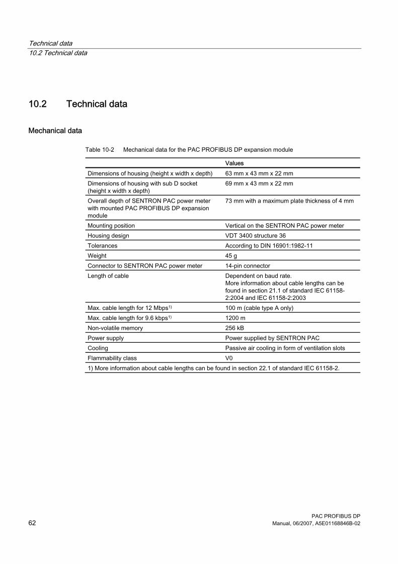
Table 10-2 Mechanical data for the PAC PROFIBUS DP expansion module
Values Dimensions of housing (height x width x depth) 63 mm x 43 mm x 22 mm Dimensions of housing with sub D socket (height x width x depth)
69 mm x 43 mm x 22 mm
Overall depth of SENTRON PAC power meter with mounted PAC PROFIBUS DP expansion module
73 mm with a maximum plate thickness of 4 mm
Mounting position Vertical on the SENTRON PAC power meter Housing design VDT 3400 structure 36 Tolerances According to DIN 16901:1982-11 Weight 45 g Connector to SENTRON PAC power meter 14-pin connector Length of cable Dependent on baud rate.
More information about cable lengths can be found in section 21.1 of standard IEC 61158-2:2004 and IEC 61158-2:2003
Max. cable length for 12 Mbps1) 100 m (cable type A only) Max. cable length for 9.6 kbps1) 1200 m Non-volatile memory 256 kB Power supply Power supplied by SENTRON PAC Cooling Passive air cooling in form of ventilation slots Flammability class V0 1) More information about cable lengths can be found in section 22.1 of standard IEC 61158-2.
Technical data 10.2 Technical data
PAC PROFIBUS DP Manual, 06/2007, A5E01168846B-02 63
Electrical data
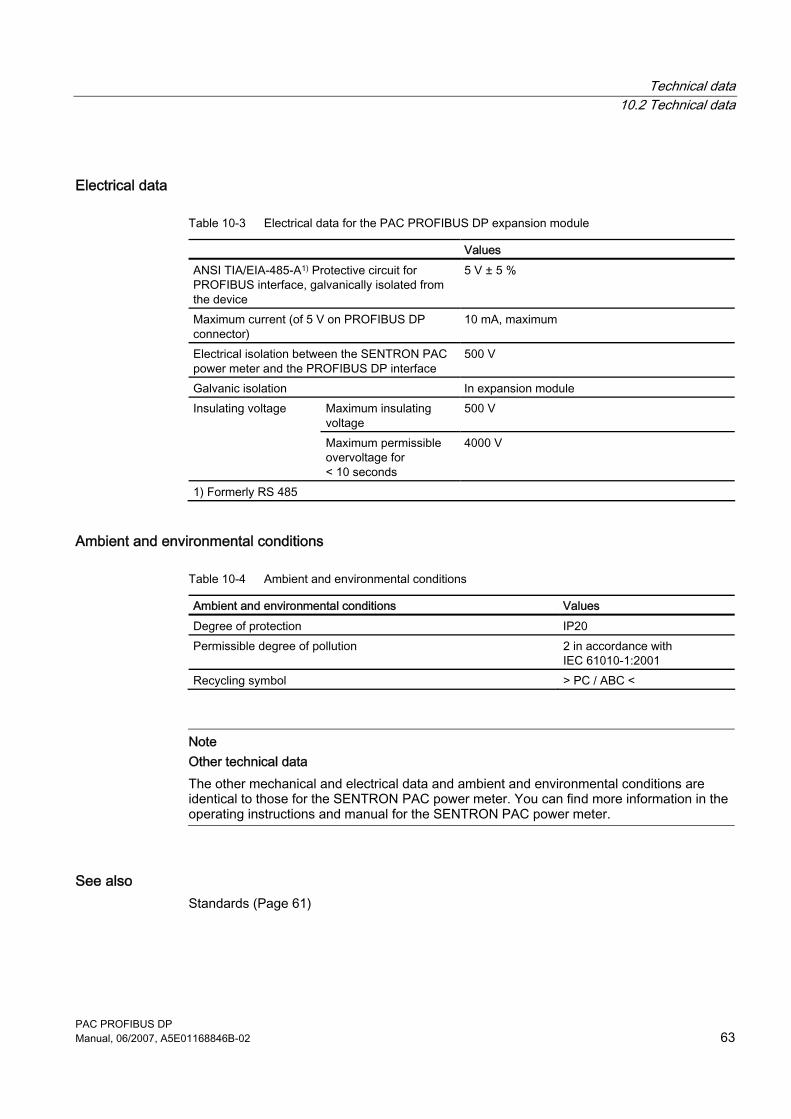
Table 10-3 Electrical data for the PAC PROFIBUS DP expansion module
Values ANSI TIA/EIA-485-A1) Protective circuit for PROFIBUS interface, galvanically isolated from the device
5 V ± 5 %
Maximum current (of 5 V on PROFIBUS DP connector)
10 mA, maximum
Electrical isolation between the SENTRON PAC power meter and the PROFIBUS DP interface
500 V
Galvanic isolation In expansion module Maximum insulating voltage
500 V Insulating voltage
Maximum permissible overvoltage for < 10 seconds
4000 V
1) Formerly RS 485
Ambient and environmental conditions
Table 10-4 Ambient and environmental conditions
Ambient and environmental conditions Values Degree of protection IP20 Permissible degree of pollution 2 in accordance with
IEC 61010-1:2001 Recycling symbol > PC / ABC <
Note Other technical data The other mechanical and electrical data and ambient and environmental conditions are identical to those for the SENTRON PAC power meter. You can find more information in the operating instructions and manual for the SENTRON PAC power meter.
See also Standards (Page 61)
Technical data 10.3 Communication interface
PAC PROFIBUS DP 64 Manual, 06/2007, A5E01168846B-02
10.3 Communication interface
Technical data
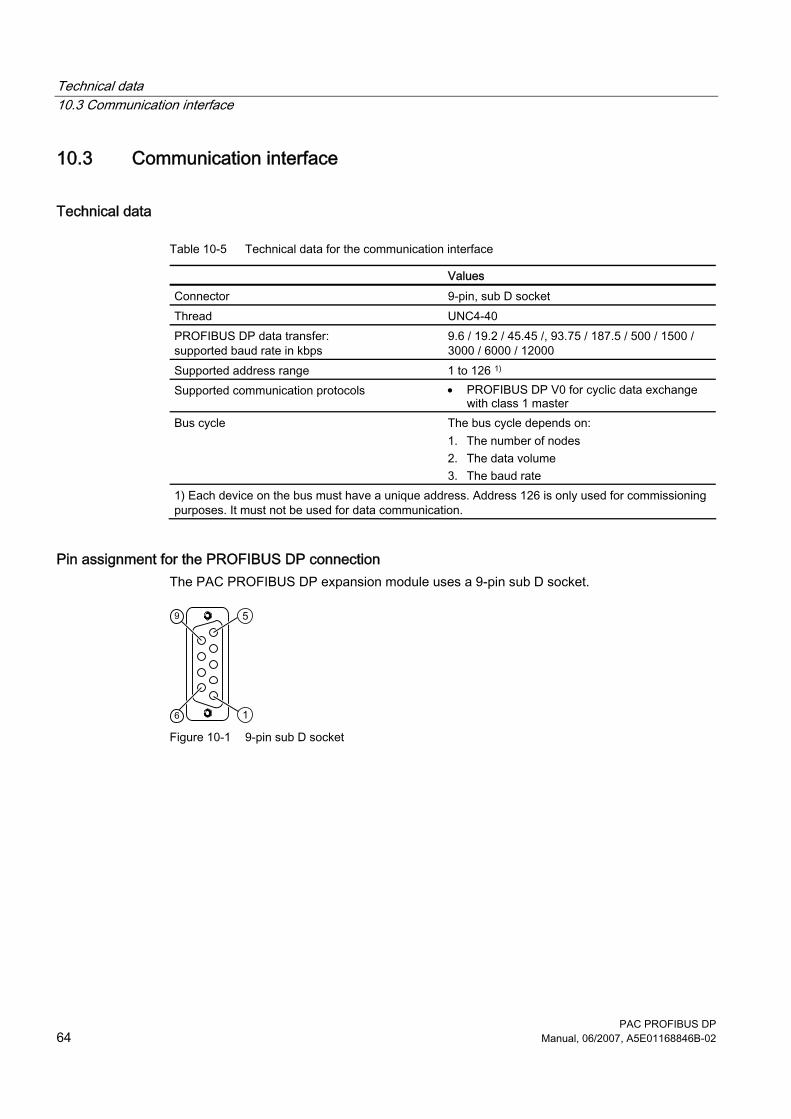
Table 10-5 Technical data for the communication interface
Values Connector 9-pin, sub D socket Thread UNC4-40 PROFIBUS DP data transfer: supported baud rate in kbps
9.6 / 19.2 / 45.45 /, 93.75 / 187.5 / 500 / 1500 / 3000 / 6000 / 12000
Supported address range 1 to 126 1) Supported communication protocols • PROFIBUS DP V0 for cyclic data exchange
with class 1 master Bus cycle The bus cycle depends on:
1. The number of nodes 2. The data volume 3. The baud rate
1) Each device on the bus must have a unique address. Address 126 is only used for commissioning purposes. It must not be used for data communication.
Pin assignment for the PROFIBUS DP connection The PAC PROFIBUS DP expansion module uses a 9-pin sub D socket.
Figure 10-1 9-pin sub D socket
Technical data 10.4 Labeling
PAC PROFIBUS DP Manual, 06/2007, A5E01168846B-02 65
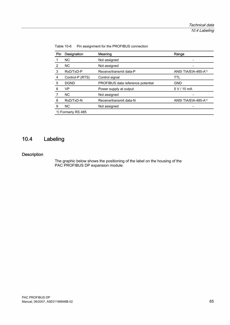
Table 10-6 Pin assignment for the PROFIBUS connection
Pin Designation Meaning Range 1 NC Not assigned - 2 NC Not assigned - 3 RxD/TxD-P Receive/transmit data-P ANSI TIA/EIA-485-A1) 4 Control-P (RTS) Control signal TTL 5 DGND PROFIBUS data reference potential GND 6 VP Power supply at output 5 V / 10 mA 7 NC Not assigned - 8 RxD/TxD-N Receive/transmit data-N ANSI TIA/EIA-485-A1) 9 NC Not assigned - 1) Formerly RS 485
10.4 Labeling
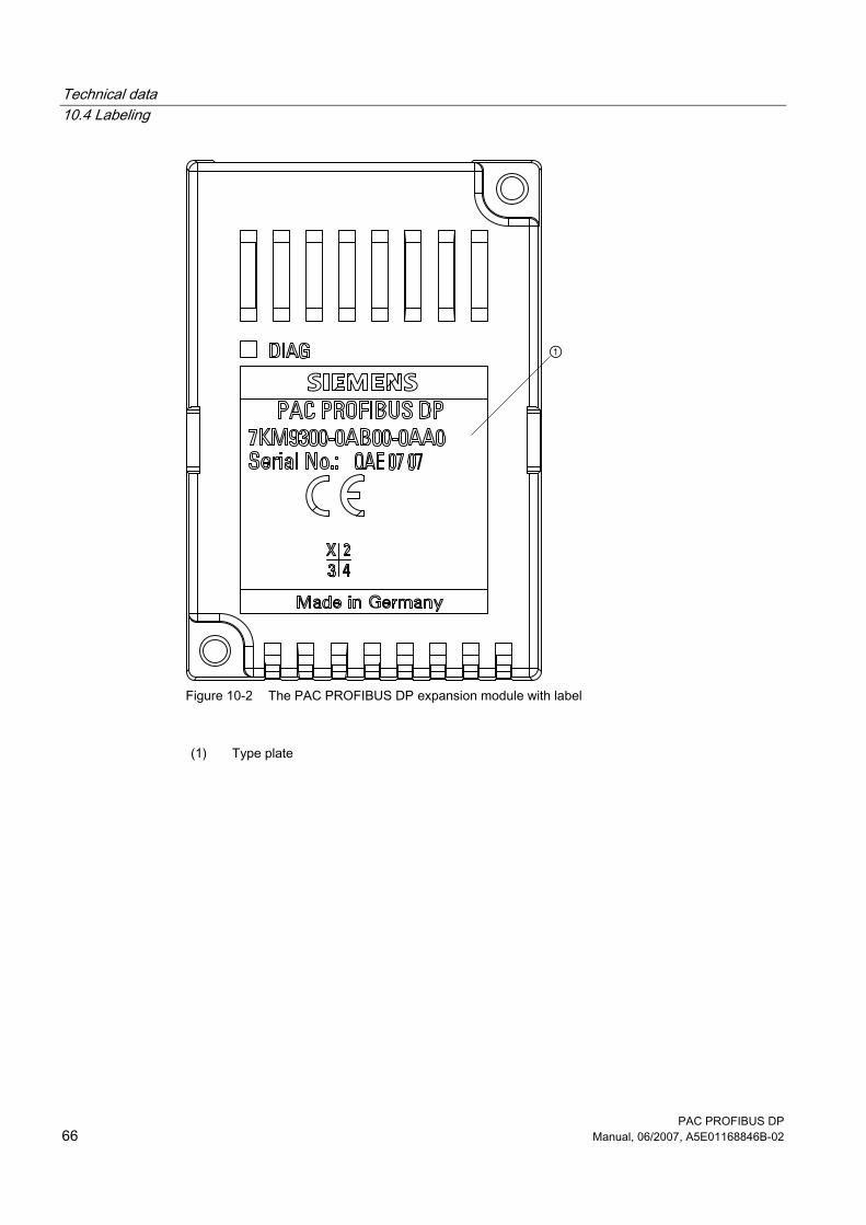
Description The graphic below shows the positioning of the label on the housing of the PAC PROFIBUS DP expansion module.
Technical data 10.4 Labeling
PAC PROFIBUS DP 66 Manual, 06/2007, A5E01168846B-02
Figure 10-2 The PAC PROFIBUS DP expansion module with label
(1) Type plate
Technical data 10.4 Labeling
PAC PROFIBUS DP Manual, 06/2007, A5E01168846B-02 67
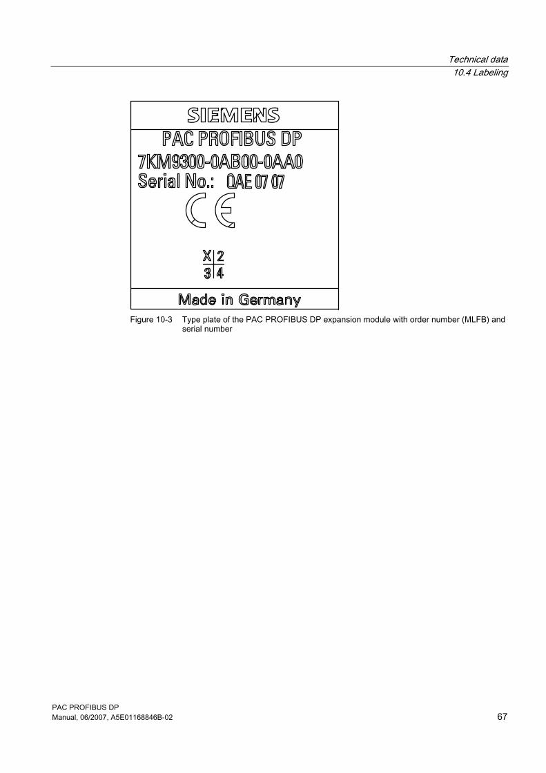
Figure 10-3 Type plate of the PAC PROFIBUS DP expansion module with order number (MLFB) and
serial number

PAC PROFIBUS DP Manual, 06/2007, A5E01168846B-02 69
Dimension sheets 1111.1 Dimension sheets
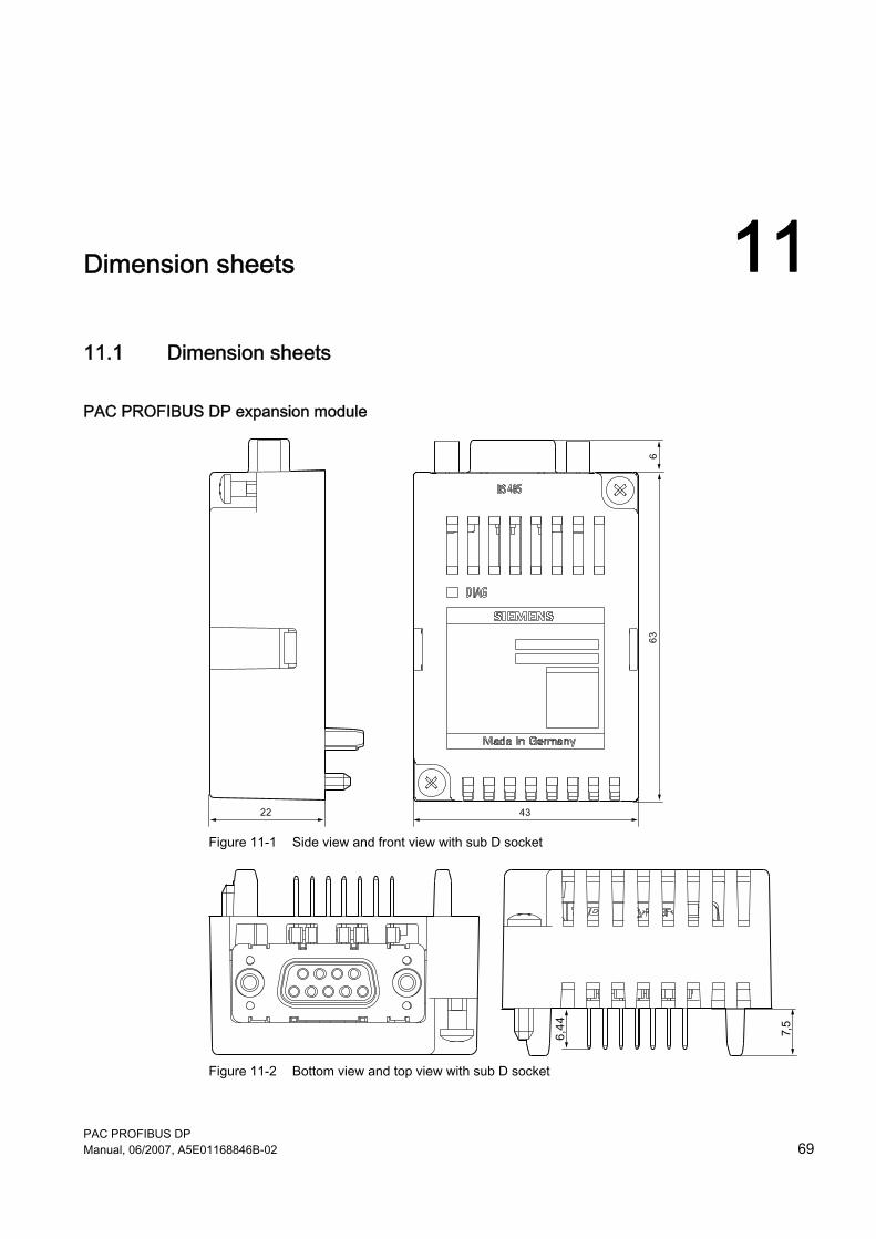
PAC PROFIBUS DP expansion module
Figure 11-1 Side view and front view with sub D socket
Figure 11-2 Bottom view and top view with sub D socket

Dimension sheets 11.1 Dimension sheets
PAC PROFIBUS DP 70 Manual, 06/2007, A5E01168846B-02
PAC PROFIBUS DP Manual, 06/2007, A5E01168846B-02 71
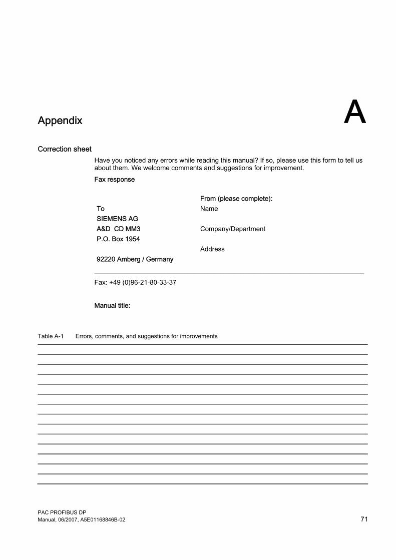
Appendix ACorrection sheet
Have you noticed any errors while reading this manual? If so, please use this form to tell us about them. We welcome comments and suggestions for improvement. Fax response
From (please complete): To SIEMENS AG A&D CD MM3 P.O. Box 1954 92220 Amberg / Germany
Name Company/Department Address
_________________________________________________________________________________ Fax: +49 (0)96-21-80-33-37 Manual title:
Table A-1 Errors, comments, and suggestions for improvements

Appendix
PAC PROFIBUS DP 72 Manual, 06/2007, A5E01168846B-02
PAC PROFIBUS DP Manual, 06/2007, A5E01168846B-02 73
ESD directives BB.1 Electrostatic sensitive devices (ESD)
ESD components are destroyed by voltage and energy far below the limits of human perception. Voltages of this kind occur as soon as a device or an assembly is touched by a person who is not electrostatically discharged. ESD components which have been subject to such voltage are usually not recognized immediately as being defective, because the malfunction does not occur until after a longer period of operation.
ESD Guidelines
CAUTION Electrostatic sensitive devices Electronic modules contain components that can be destroyed by electrostatic discharge. These modules can be easily destroyed or damaged by improper handling. • You must discharge your body electrostatically immediately before touching an
electronic component. To do this, touch a conductive, grounded object, e.g., a bare metal part of a switch cabinet or the water pipe.
• Always hold the component by the plastic enclosure. • Electronic modules should not be brought into contact with electrically insulating
materials such as plastic film, plastic parts, insulating table supports or clothing made of synthetic fibers.
• Always place electrostatic sensitive devices on conductive bases. • Always store and transport electronic modules or components in ESD-safe conductive
packaging, e.g. metallized plastic or metal containers. Leave the component in its packaging until installation.
CAUTION Storage and transport If you have to store or transport the component in non-conductive packaging, you must first pack the component in ESD-safe, conductive material, e.g., conductive foam rubber, ESD bag.
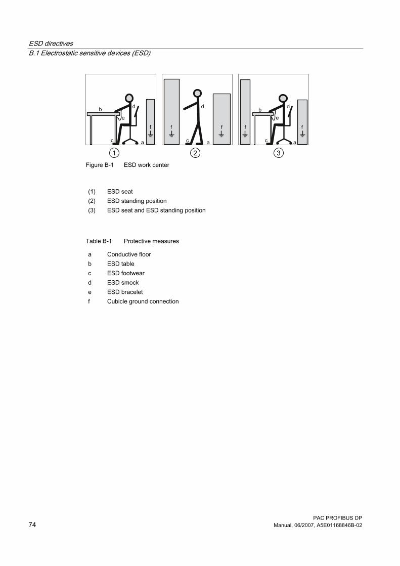
The diagrams below illustrate the required ESD protective measures for electrostatic sensitive devices.
ESD directives B.1 Electrostatic sensitive devices (ESD)
PAC PROFIBUS DP 74 Manual, 06/2007, A5E01168846B-02
Figure B-1 ESD work center
(1) ESD seat (2) ESD standing position (3) ESD seat and ESD standing position
Table B-1 Protective measures
a Conductive floor b ESD table c ESD footwear d ESD smock e ESD bracelet f Cubicle ground connection
PAC PROFIBUS DP Manual, 06/2007, A5E01168846B-02 75
List of abbreviations CC.1 Abbreviations
Overview
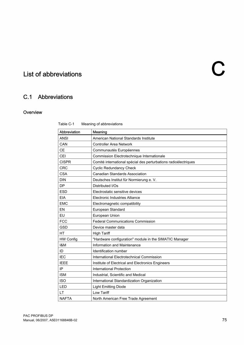
Table C-1 Meaning of abbreviations
Abbreviation Meaning ANSI American National Standards Institute CAN Controller Area Network CE Communautés Européennes CEI Commission Electrotechnique Internationale CISPR Comité international spécial des perturbations radioélectriques CRC Cyclic Redundancy Check CSA Canadian Standards Association DIN Deutsches Institut für Normierung e. V. DP Distributed I/Os ESD Electrostatic sensitive devices EIA Electronic Industries Alliance EMC Electromagnetic compatibility EN European Standard EU European Union FCC Federal Communications Commission GSD Device master data HT High Tariff HW Config "Hardware configuration" module in the SIMATIC Manager I&M Information and Maintenance ID Identification number IEC International Electrotechnical Commission IEEE Institute of Electrical and Electronics Engineers IP International Protection ISM Industrial, Scientific and Medical ISO International Standardization Organization LED Light Emitting Diode LT Low Tariff NAFTA North American Free Trade Agreement
List of abbreviations C.1 Abbreviations
PAC PROFIBUS DP 76 Manual, 06/2007, A5E01168846B-02
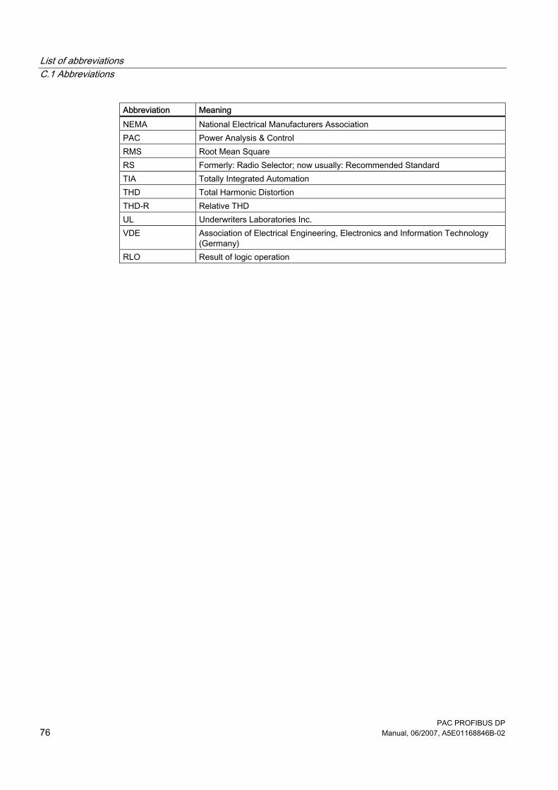
Abbreviation Meaning NEMA National Electrical Manufacturers Association PAC Power Analysis & Control RMS Root Mean Square RS Formerly: Radio Selector; now usually: Recommended Standard TIA Totally Integrated Automation THD Total Harmonic Distortion THD-R Relative THD UL Underwriters Laboratories Inc. VDE Association of Electrical Engineering, Electronics and Information Technology
(Germany) RLO Result of logic operation
PAC PROFIBUS DP Manual, 06/2007, A5E01168846B-02 77
Glossary
Baud rate The baud rate is the rate of data transmission. It indicates the number of bits transferred in one second.
Bus Shared transmission path over which all bus nodes are connected. It has two defined ends. In the case of PROFIBUS, the bus is a twisted pair or optical fiber cable.
Bus system All nodes physically connected to a bus cable form a bus system.
Diagnostics The detection, localization, visualization and further evaluation of errors, disturbances and messages. Diagnostics offers monitoring functions that automatically run while the system is in operation. This reduces startup times and standstill times. Plant availability increases.
Equipotential bonding Electrical connection (equipotential bonding conductor) which brings the bodies of electronic equipment and foreign conductive bodies to an equal or approximately equal potential. This prevents disruptive or dangerous voltages between these bodies.
FREEZE FREEZE is a control command from the PROFIBUS DP master to a group of PROFIBUS DP slaves. Upon receiving the FREEZE control command, the PROFIBUS DP slave freezes the inputs at their current states and transfers them to the PROFIBUS DP master in cycles. The PROFIBUS DP slave freezes its input status again after each new FREEZE command. The input data will be cyclically transferred to the PROFIBUS DP master again only after the PROFIBUS DP master has issued the UNFREEZE control command.
Glossary
PAC PROFIBUS DP 78 Manual, 06/2007, A5E01168846B-02
Master When a master is in possession of the token, it can send data to other nodes and request data from other nodes.
Node Device which can send, receive or amplify data on the bus, e.g., PROFIBUS DP master, PROFIBUS DP slave.
PROFIBUS PROCESS FIELDBUS, a European process and fieldbus standard defined in the PROFIBUS standard EN 50170, Volume 2 PROFIBUS. Specifies the functional, electrical and mechanical characteristics of a serial bit stream fieldbus system. PROFIBUS is a bus system that connects PROFIBUS-compatible automation systems and field devices together at the cell level and field level.
PROFIBUS address Every bus node receives a unique PROFIBUS address. The bus node is identified on PROFIBUS with this address. The factory address setting for the PAC PROFIBUS DP expansion module is address 126. Addresses 1 to 126 are permissible.
Slave A slave can only exchange data after being requested to by the master.
SYNC With the SYNC control command the PROFIBUS DP master prompts the PROFIBUS DP slave to freeze the output statuses at their value at that moment. With the subsequent frames, the PROFIBUS DP slave stores the output data, but the output statuses remain unchanged. After each new SYNC control command, the PROFIBUS DP slave sets the outputs it has saved as output data. The outputs are not updated cyclically again until the PROFIBUS DP master has sent an UNSYNC control command.
PAC PROFIBUS DP Manual, 06/2007, A5E01168846B-02 79
Index
A Active energy export, 32 Active energy import, 32 Active energy import tariff 1, 24 Active power
Total, 24 Address, 35, 36, 59
Change, 36 Address range
Supported, 59 Ambient conditions, 59 ANSI TIA/EIA 485 A connection, 19 ANSI TIA/EIA 485 A protective circuit, 58 Apparent energy, 32 Apply supply voltage, 15 Area of application, 11 Assembly, 15, 17 Avoid condensation, 16
B Basic type, 23 Basic type 1, 23, 24, 27 Basic type 2, 23, 24
Length of message, 24 Baud rate, 11, 15, 20, 23, 35, 59
Supported, 59 Bottom view, 63 Bus connector, 19, 49 Bus cycle, 59 Bus fault, 48 Bus installation, 49 Bus terminating resistor, 19 Bus termination, 19 Bus traffic, 12
C Cable length, 20 CD
Contents, 6 Change tariff, 27
Cleaning, 19, 45 Clear memory contents, 27 Commands, 27 Commissioning, 36 Communication, 48, 51, 52 Communication error
Permanent, 51 Communication interface, 59 Communication parameters, 35 Communication protocols
Supported, 59 Communication status, 47 Component diagnostics, 26 Condensation, 21 Conductive floor, 68 Configuration, 11, 25 Configure, 15 Connector, 59
Defective, 45 Connector to SENTRON PAC power meter, 58 Contact
Technical problems, 7 Contacts
In your region, 7 Contents
CD, 6 Control bytes, 27 Cooling, 58 Correction sheet, 65 Cross-tip screwdriver, 17 Cubicle ground connection, 68 Current terminals, 18 Cyclic data exchange, 23, 25 Cyclic data transfer, 11
Index
PAC PROFIBUS DP 80 Manual, 06/2007, A5E01168846B-02
D Danger of overheating, 17 Data exchange
Cyclic, 23 Data invalid, 51 Data volume, 23 Default settings, 35 Degree of protection, 59 Detergents
Damage, 45 Device diagnostic interrupts, 51 Device diagnostics, 26, 27, 47, 49, 50
Structure, 50 Device status, 26 Diagnostic messages, 51 Diagnostic telegram, 50 Diagnostics LED, 47 Digital data communications for measurement and control, 57 Digital input, 33 Digital output, 33 Digital status information, 24, 25 Dimensions of housing, 57 Disassembly, 21 Discharge, 18, 45, 67 Disconnect the system, 9 Disposal, 46 Double format, 32
E Edge transition, 27 Electrical data, 58 Electrical isolation, 58 Electrostatic sensitive devices, 67 Endangering of operation, 20 Energy counter
Reset, 27 Enhanced diagnostics, 47 Environmental conditions, 59 Equipotential bonding, 20 ESD bracelet, 68 ESD footwear, 68 ESD Guidelines, 16, 17, 21, 67 ESD protective measures, 67 ESD seat, 68 ESD smock, 68 ESD standing position, 68 ESD table, 68
F Factory settings, 35 Fault display, 47 Features, 11 Firmware incompatible, 51 Flammability class, 58 Float format, 32 Fluctuations of temperature, 16 Front view, 63 Further basic type
Structure, 25
G Galvanic isolation, 12, 58 Ground, 9, 20 GSD file, 6, 11, 15, 23, 35, 49
Language, 37 Guide pin, 13, 18
H Hardware fault, 48 Housing design, 58 Humidity, 19 HW Config, 38
I Initialization phase, 49, 52 Input data, 24 Installation guidelines, 20 Installation location, 15 Insulating voltage, 58
maximum, 58 Intended use, 11
L Labeling, 60 Language, 35 LED, 13, 47, 48, 52 Length of cable, 58 Level sensitive, 27 Limit values, 33 Loss of warranty, 45
Index
PAC PROFIBUS DP Manual, 06/2007, A5E01168846B-02 81
M Make sure the equipment is de-energized., 9 Manufacturer's ID, 47 Master, 47, 49 Master-slave principle, 11 Maximum values
Reset, 27 Measured values, 53 Measured variables, 23, 27 Mechanical data, 57 Message frame, 23 Minimum values
Reset, 27 Moisture, 19 Mounting position, 58
N Non-volatile memory, 58 Number of nodes, 23
O Off peak, 27 On peak, 27 Online support, 7 Order number, 62 Orientation aids, 5 Overall depth, 58 Overvoltage
Maximum permissible, 58
P Packaging, 16 Parameter assignment, 48, 53 Parameter assignment error, 48 Parameterize, 15 Parameters for configuration, 52 Perform checks, 16 Permissible degree of pollution, 59 Phase current, 24 Pin, 13, 17, 45 PIN assignment, 60 Power failure, 55 Power meter, 52 Power on, 52 Power supply, 58 PROFIBUS adaptor plug, 19 PROFIBUS address, 15, 48, 49, 55
PROFIBUS address of the master, 47 PROFIBUS cable, 20 PROFIBUS connection, 60 PROFIBUS DP master, 37 PROFIBUS DP Master, 12, 15 PROFIBUS DP slave, 12, 37 PROFIBUS functions, 13 PROFIBUS ID number, 37 PROFIBUS network, 15 Pulse rate, 26
Q Quantity structure, 23
R Reactive energy export, 32 Reactive energy import, 32 Recycling, 46 Recycling symbol, 59 Repair, 45 Required basic knowledge, 5 Response monitoring, 50 RS 485, 19 RS 485 protective circuit, 58
S Safe isolation from supply, 18 Safety notes, 9 Safety rules, 9 Secure against reconnection, 9 Serial number, 62 Set language, 15, 52 Short-circuit, 9 Side view, 63 SIMATIC environment, 35 SIMATIC Manager, 38 Slave, 47, 48, 49 Slave diagnostics in accordance with standard, 47 Status 1, 49 Status 2, 49 Status 3, 50 Status bytes, 53 Status display, 47 STEP 7, 35, 51 Storage, 16 Storage, 67 Structure, 12 Sub D connector, 17, 18, 21
Index
PAC PROFIBUS DP 82 Manual, 06/2007, A5E01168846B-02
Sub D socket, 13, 18, 21, 58, 59, 63 Support
Address, 7 Online, 7 Technical, 8 Technical, 46
Support address, 7 Switch outputs, 27 Synchronization pulse, 25 System status, 25
T Tariff
Changeover, 27 Tasks, 12 Technical data, 59 Technical problems
Contact, 7 Technical support, 8, 46 Temperature compensation, 21 Thread, 59 Tightening torque, 18 Tolerances, 58 Tools, 17 Top view, 63 Total power factor, 24 Transport, 67 Type of power meter connected, 35 Type plate, 61
U Unpacking, 16 Update firmware, 51
V Ventilation slots, 13, 17, 21, 58 Voltage, 24, 55 Voltage terminals, 18
W Watchdog function, 12 Weight, 58 Wetness, 19 Working measured variables, 32


![BU 2700 PROFIBUS DP Busschnittstelle - NORD€¦ · Sicherheit/PROFIBUS DP [BU 2700]/Bestimmungsgemäße Ver wendung PROFIBUS DP @ 8\mod_1461835577600_6.docx @ 2249428 @ 2 @ 1 2.1](https://img.pdfslide.net/doc/110x75/5eab6d581394d0309b74d9e9/bu-2700-profibus-dp-busschnittstelle-nord-sicherheitprofibus-dp-bu-2700bestimmungsgeme.jpg)