Embed Size (px)
Citation preview
DDEC VI ELECTRONIC CONTROLS APPLICATION AND INSTALLATION
4 INPUTS AND OUTPUTS
Section Page
4.1 INPUTS ................................................................................................... 4-3
4.2 SWITCH INPUTS RECEIVED OVER J1939 DATA LINK ....................... 4-27
4.3 DIGITAL OUTPUTS – CPC ..................................................................... 4-29
4.4 ANALOG OUTPUTS – CPC ................................................................... 4-49
4.5 PWM OUTPUT — CPC .......................................................................... 4-51
All information subject to change without notice. (Rev. 03/07) 4-17SA827 0703 Copyright © 2007 DETROIT DIESEL CORPORATION

INPUTS AND OUTPUTS
THIS PAGE INTENTIONALLY LEFT BLANK
4-2 All information subject to change without notice. (Rev. 03/07)7SA827 0703 Copyright © 2007 DETROIT DIESEL CORPORATION
DDEC VI ELECTRONIC CONTROLS APPLICATION AND INSTALLATION
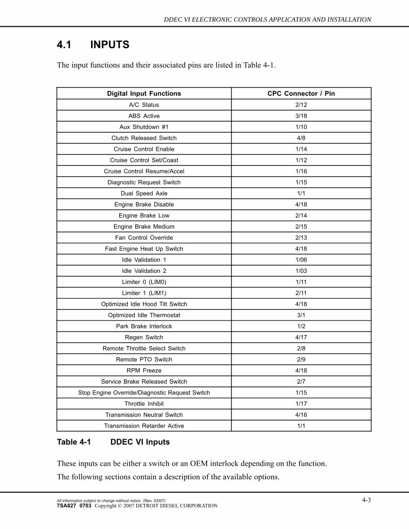
4.1 INPUTS
The input functions and their associated pins are listed in Table 4-1.
Digital Input Functions CPC Connector / PinA/C Status 2/12
ABS Active 3/18
Aux Shutdown #1 1/10
Clutch Released Switch 4/8
Cruise Control Enable 1/14
Cruise Control Set/Coast 1/12
Cruise Control Resume/Accel 1/16
Diagnostic Request Switch 1/15
Dual Speed Axle 1/1
Engine Brake Disable 4/18
Engine Brake Low 2/14
Engine Brake Medium 2/15
Fan Control Override 2/13
Fast Engine Heat Up Switch 4/18
Idle Validation 1 1/06
Idle Validation 2 1/03
Limiter 0 (LIM0) 1/11
Limiter 1 (LIM1) 2/11
Optimized Idle Hood Tilt Switch 4/18
Optimized Idle Thermostat 3/1
Park Brake Interlock 1/2
Regen Switch 4/17
Remote Throttle Select Switch 2/8
Remote PTO Switch 2/9
RPM Freeze 4/18
Service Brake Released Switch 2/7
Stop Engine Override/Diagnostic Request Switch 1/15
Throttle Inhibit 1/17
Transmission Neutral Switch 4/16
Transmission Retarder Active 1/1
Table 4-1 DDEC VI Inputs
These inputs can be either a switch or an OEM interlock depending on the function.
The following sections contain a description of the available options.
All information subject to change without notice. (Rev. 03/07) 4-37SA827 0703 Copyright © 2007 DETROIT DIESEL CORPORATION
INPUTS AND OUTPUTS
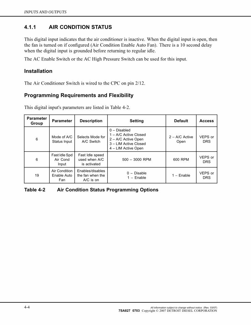
4.1.1 AIR CONDITION STATUS
This digital input indicates that the air conditioner is inactive. When the digital input is open, thenthe fan is turned on if configured (Air Condition Enable Auto Fan). There is a 10 second delaywhen the digital input is grounded before returning to regular idle.
The AC Enable Switch or the AC High Pressure Switch can be used for this input.
Installation
The Air Conditioner Switch is wired to the CPC on pin 2/12.
Programming Requirements and Flexibility
This digital input's parameters are listed in Table 4-2.
ParameterGroup Parameter Description Setting Default Access
6 Mode of A/CStatus Input
Selects Mode forA/C Switch
0 – Disabled1 – A/C Active Closed2 – A/C Active Open3 – LIM Active Closed4 – LIM Active Open
2 – A/C ActiveOpen
VEPS orDRS
6Fast Idle SpdAir CondInput
Fast Idle speedused when A/Cis activated
500 – 3000 RPM 600 RPM VEPS orDRS
19Air ConditionEnable Auto
Fan
Enables/disablesthe fan when the
A/C is on
0 – Disable1 – Enable 1 – Enable VEPS or
DRS
Table 4-2 Air Condition Status Programming Options
4-4 All information subject to change without notice. (Rev. 03/07)7SA827 0703 Copyright © 2007 DETROIT DIESEL CORPORATION
DDEC VI ELECTRONIC CONTROLS APPLICATION AND INSTALLATION
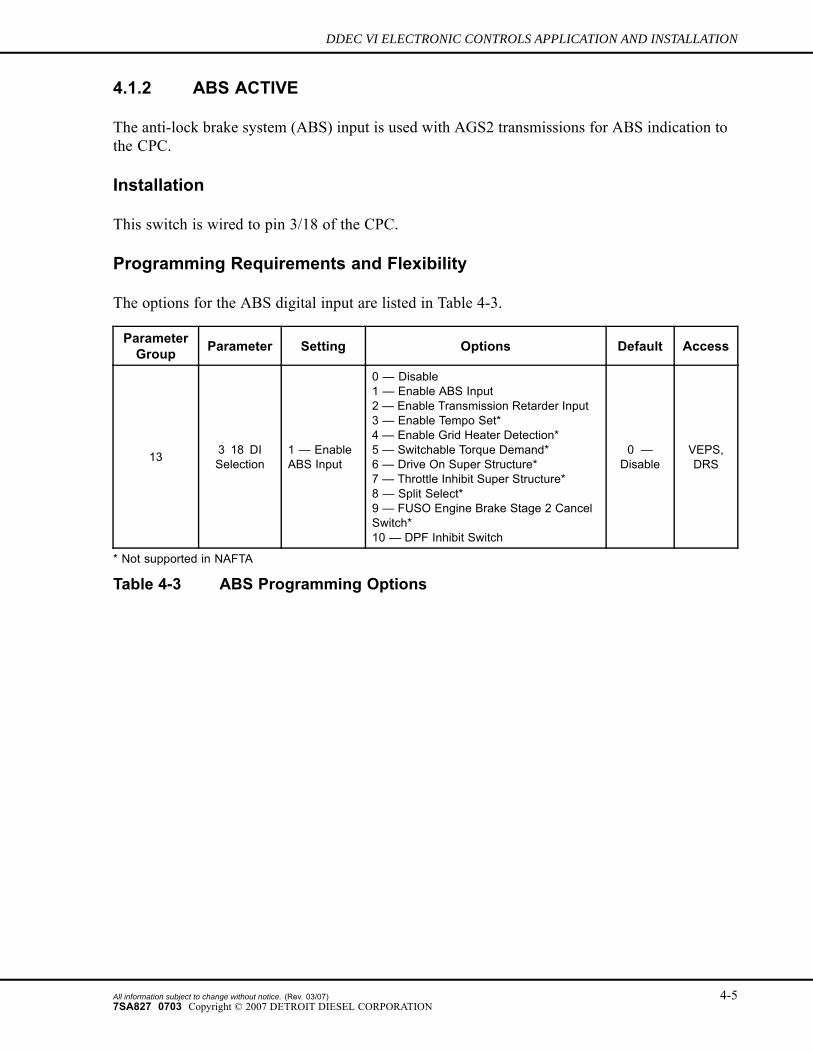
4.1.2 ABS ACTIVE
The anti-lock brake system (ABS) input is used with AGS2 transmissions for ABS indication tothe CPC.
Installation
This switch is wired to pin 3/18 of the CPC.
Programming Requirements and Flexibility
The options for the ABS digital input are listed in Table 4-3.
ParameterGroup Parameter Setting Options Default Access
13 3 18 DISelection
1 — EnableABS Input
0 — Disable1 — Enable ABS Input2 — Enable Transmission Retarder Input3 — Enable Tempo Set*4 — Enable Grid Heater Detection*5 — Switchable Torque Demand*6 — Drive On Super Structure*7 — Throttle Inhibit Super Structure*8 — Split Select*9 — FUSO Engine Brake Stage 2 CancelSwitch*10 — DPF Inhibit Switch
0 —Disable
VEPS,DRS
* Not supported in NAFTA
Table 4-3 ABS Programming Options
All information subject to change without notice. (Rev. 03/07) 4-57SA827 0703 Copyright © 2007 DETROIT DIESEL CORPORATION
INPUTS AND OUTPUTS
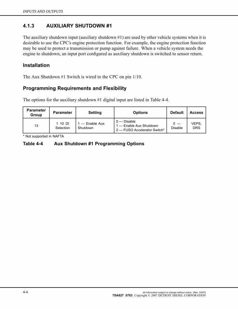
4.1.3 AUXILIARY SHUTDOWN #1
The auxiliary shutdown input (auxiliary shutdown #1) are used by other vehicle systems when it isdesirable to use the CPC's engine protection function. For example, the engine protection functionmay be used to protect a transmission or pump against failure. When a vehicle system needs theengine to shutdown, an input port configured as auxiliary shutdown is switched to sensor return.
Installation
The Aux Shutdown #1 Switch is wired to the CPC on pin 1/10.
Programming Requirements and Flexibility
The options for the auxiliary shutdown #1 digital input are listed in Table 4-4.
ParameterGroup Parameter Setting Options Default Access
13 1 10 DISelection
1 — Enable AuxShutdown
0 — Disable1 — Enable Aux Shutdown2 — FUSO Accelerator Switch*
0 —Disable
VEPS,DRS
* Not supported in NAFTA
Table 4-4 Aux Shutdown #1 Programming Options
4-6 All information subject to change without notice. (Rev. 03/07)7SA827 0703 Copyright © 2007 DETROIT DIESEL CORPORATION
DDEC VI ELECTRONIC CONTROLS APPLICATION AND INSTALLATION
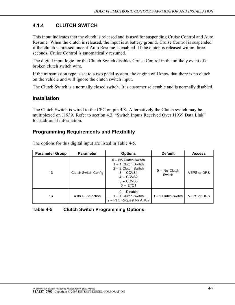
4.1.4 CLUTCH SWITCH
This input indicates that the clutch is released and is used for suspending Cruise Control and AutoResume. When the clutch is released, the input is at battery ground. Cruise Control is suspendedif the clutch is pressed once if Auto Resume is enabled. If the clutch is released within threeseconds, Cruise Control is automatically resumed.
The digital input logic for the Clutch Switch disables Cruise Control in the unlikely event of abroken clutch switch wire.
If the transmission type is set to a two pedal system, the engine will know that there is no clutchon the vehicle and will ignore the clutch switch input.
The Clutch Switch is a normally closed switch. It is customer selectable and is normally disabled.
Installation
The Clutch Switch is wired to the CPC on pin 4/8. Alternatively the Clutch switch may bemultiplexed on J1939. Refer to section 4.2, “Switch Inputs Received Over J1939 Data Link”for additional information.
Programming Requirements and Flexibility
The options for this digital input are listed in Table 4-5.
Parameter Group Parameter Options Default Access
13 Clutch Switch Config
0 – No Clutch Switch1 – 1 Clutch Switch2 – 2 Clutch Switch
3 – CCVS14 – CCVS25 – CCVS36 – ETC1
0 – No ClutchSwitch VEPS or DRS
13 4 08 DI Selection0 – Disable
1 – 1 Clutch Switch2 – PTO Request for AGS2
1 – 1 Clutch Switch VEPS or DRS
Table 4-5 Clutch Switch Programming Options
All information subject to change without notice. (Rev. 03/07) 4-77SA827 0703 Copyright © 2007 DETROIT DIESEL CORPORATION
INPUTS AND OUTPUTS
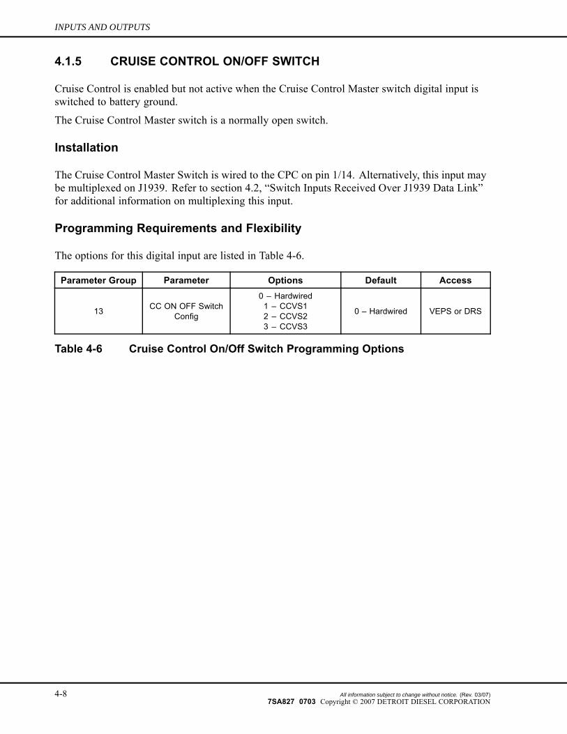
4.1.5 CRUISE CONTROL ON/OFF SWITCH
Cruise Control is enabled but not active when the Cruise Control Master switch digital input isswitched to battery ground.
The Cruise Control Master switch is a normally open switch.
Installation
The Cruise Control Master Switch is wired to the CPC on pin 1/14. Alternatively, this input maybe multiplexed on J1939. Refer to section 4.2, “Switch Inputs Received Over J1939 Data Link”for additional information on multiplexing this input.
Programming Requirements and Flexibility
The options for this digital input are listed in Table 4-6.
Parameter Group Parameter Options Default Access
13 CC ON OFF SwitchConfig
0 – Hardwired1 – CCVS12 – CCVS23 – CCVS3
0 – Hardwired VEPS or DRS
Table 4-6 Cruise Control On/Off Switch Programming Options
4-8 All information subject to change without notice. (Rev. 03/07)7SA827 0703 Copyright © 2007 DETROIT DIESEL CORPORATION
DDEC VI ELECTRONIC CONTROLS APPLICATION AND INSTALLATION
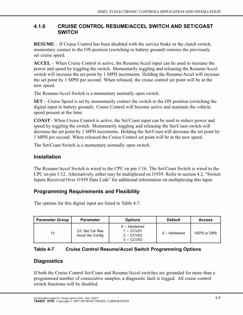
4.1.6 CRUISE CONTROL RESUME/ACCEL SWITCH AND SET/COASTSWITCH
RESUME – If Cruise Control has been disabled with the service brake or the clutch switch,momentary contact to the ON position (switching to battery ground) restores the previouslyset cruise speed.
ACCEL – When Cruise Control is active, the Resume/Accel input can be used to increase thepower and speed by toggling the switch. Momentarily toggling and releasing the Resume/Accelswitch will increase the set point by 1 MPH increments. Holding the Resume/Accel will increasethe set point by 1 MPH per second. When released, the cruise control set point will be at thenew speed.
The Resume/Accel Switch is a momentary normally open switch.
SET – Cruise Speed is set by momentarily contact the switch to the ON position (switching thedigital input to battery ground). Cruise Control will become active and maintain the vehiclespeed present at the time.
COAST– When Cruise Control is active, the Set/Coast input can be used to reduce power andspeed by toggling the switch. Momentarily toggling and releasing the Set/Coast switch willdecrease the set point by 1 MPH increments. Holding the Set/Coast will decrease the set point by1 MPH per second. When released the Cruise Control set point will be at the new speed.
The Set/Coast Switch is a momentary normally open switch.
Installation
The Resume/Accel Switch is wired to the CPC on pin 1/16. The Set/Coast Switch is wired to theCPC on pin 1/12. Alternatively, either may be multiplexed on J1939. Refer to section 4.2, “SwitchInputs Received Over J1939 Data Link” for additional information on multiplexing this input.
Programming Requirements and Flexibility
The options for this digital input are listed in Table 4-7.
Parameter Group Parameter Options Default Access
13 CC Set Cst ResAccel Sw Config
0 – Hardwired1 – CCVS12 – CCVS23 – CCVS3
0 – Hardwired VEPS or DRS
Table 4-7 Cruise Control Resume/Accel Switch Programming Options
Diagnostics
If both the Cruise Control Set/Coast and Resume/Accel switches are grounded for more than aprogrammed number of consecutive samples, a diagnostic fault is logged. All cruise controlswitch functions will be disabled.
All information subject to change without notice. (Rev. 03/07) 4-97SA827 0703 Copyright © 2007 DETROIT DIESEL CORPORATION
INPUTS AND OUTPUTS
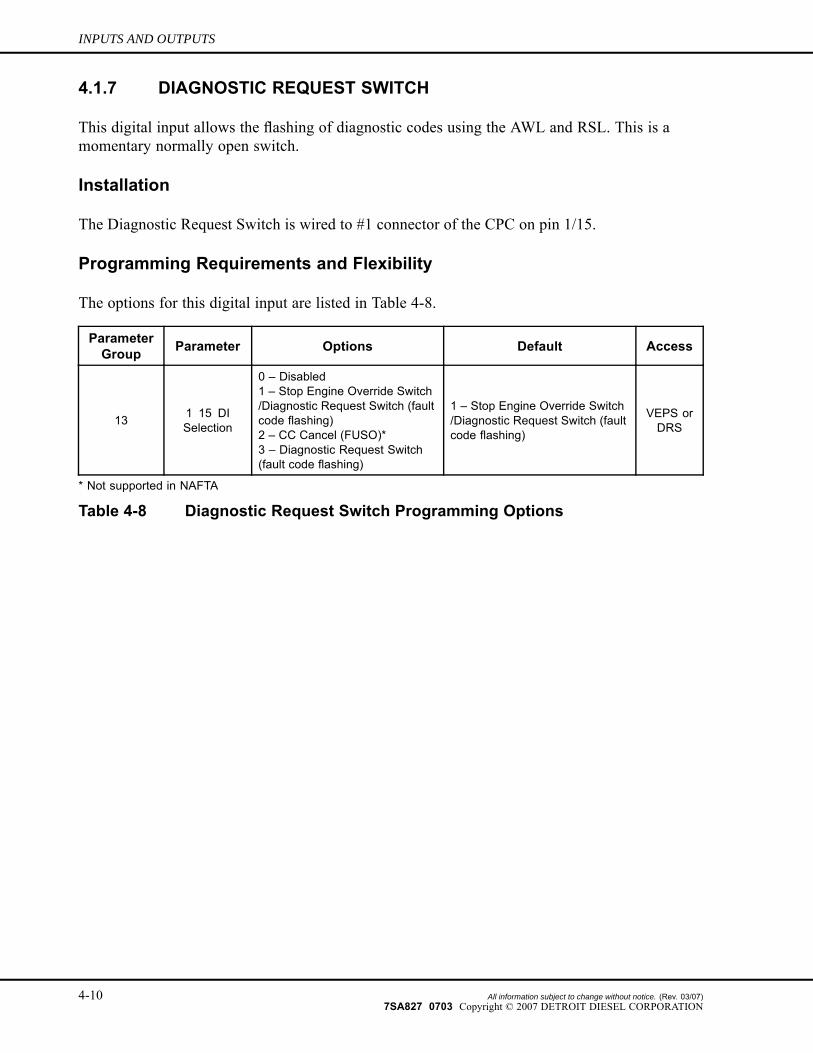
4.1.7 DIAGNOSTIC REQUEST SWITCH
This digital input allows the flashing of diagnostic codes using the AWL and RSL. This is amomentary normally open switch.
Installation
The Diagnostic Request Switch is wired to #1 connector of the CPC on pin 1/15.
Programming Requirements and Flexibility
The options for this digital input are listed in Table 4-8.
ParameterGroup Parameter Options Default Access
13 1 15 DISelection
0 – Disabled1 – Stop Engine Override Switch/Diagnostic Request Switch (faultcode flashing)2 – CC Cancel (FUSO)*3 – Diagnostic Request Switch(fault code flashing)
1 – Stop Engine Override Switch/Diagnostic Request Switch (faultcode flashing)
VEPS orDRS
* Not supported in NAFTA
Table 4-8 Diagnostic Request Switch Programming Options
4-10 All information subject to change without notice. (Rev. 03/07)7SA827 0703 Copyright © 2007 DETROIT DIESEL CORPORATION
DDEC VI ELECTRONIC CONTROLS APPLICATION AND INSTALLATION
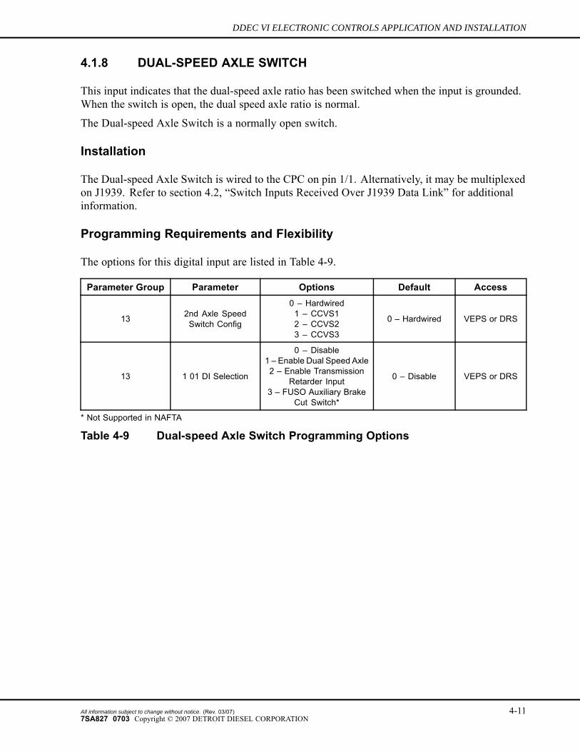
4.1.8 DUAL-SPEED AXLE SWITCH
This input indicates that the dual-speed axle ratio has been switched when the input is grounded.When the switch is open, the dual speed axle ratio is normal.
The Dual-speed Axle Switch is a normally open switch.
Installation
The Dual-speed Axle Switch is wired to the CPC on pin 1/1. Alternatively, it may be multiplexedon J1939. Refer to section 4.2, “Switch Inputs Received Over J1939 Data Link” for additionalinformation.
Programming Requirements and Flexibility
The options for this digital input are listed in Table 4-9.
Parameter Group Parameter Options Default Access
13 2nd Axle SpeedSwitch Config
0 – Hardwired1 – CCVS12 – CCVS23 – CCVS3
0 – Hardwired VEPS or DRS
13 1 01 DI Selection
0 – Disable1 – Enable Dual Speed Axle2 – Enable Transmission
Retarder Input3 – FUSO Auxiliary Brake
Cut Switch*
0 – Disable VEPS or DRS
* Not Supported in NAFTA
Table 4-9 Dual-speed Axle Switch Programming Options
All information subject to change without notice. (Rev. 03/07) 4-117SA827 0703 Copyright © 2007 DETROIT DIESEL CORPORATION
INPUTS AND OUTPUTS
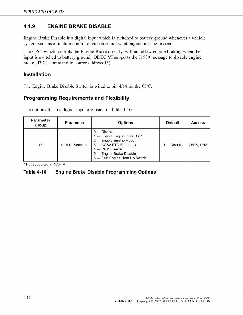
4.1.9 ENGINE BRAKE DISABLE
Engine Brake Disable is a digital input which is switched to battery ground whenever a vehiclesystem such as a traction control device does not want engine braking to occur.
The CPC, which controls the Engine Brake directly, will not allow engine braking when theinput is switched to battery ground. DDEC VI supports the J1939 message to disable enginebrake (TSC1 command to source address 15).
Installation
The Engine Brake Disable Switch is wired to pin 4/18 on the CPC.
Programming Requirements and Flexibility
The options for this digital input are listed in Table 4-10.
ParameterGroup Parameter Options Default Access
13 4 18 DI Selection
0 — Disable1 — Enable Engine Door Bus*2 — Enable Engine Hood3 — AGS2 PTO Feedback4 — RPM Freeze5 — Engine Brake Disable6 — Fast Engine Heat Up Switch
0 — Disable VEPS, DRS
* Not supported in NAFTA
Table 4-10 Engine Brake Disable Programming Options
4-12 All information subject to change without notice. (Rev. 03/07)7SA827 0703 Copyright © 2007 DETROIT DIESEL CORPORATION
DDEC VI ELECTRONIC CONTROLS APPLICATION AND INSTALLATION
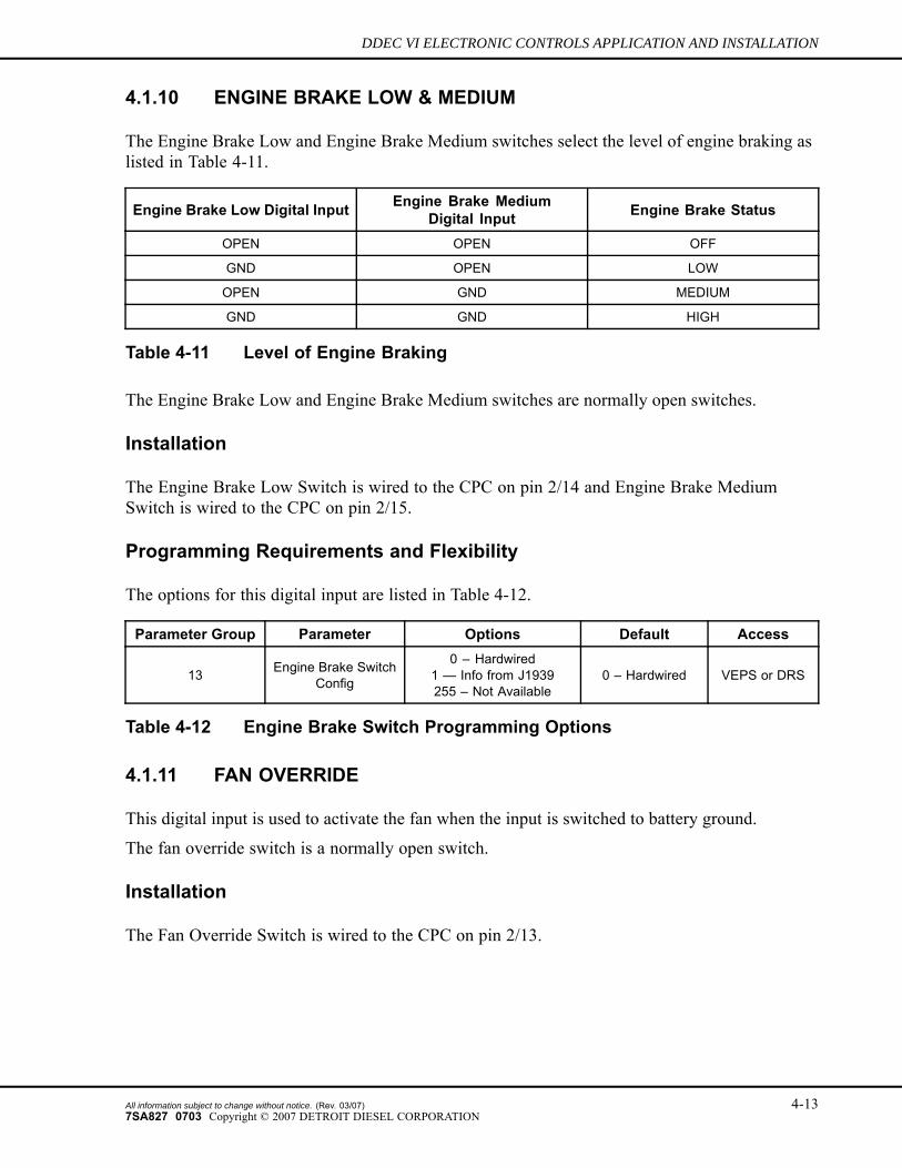
4.1.10 ENGINE BRAKE LOW & MEDIUM
The Engine Brake Low and Engine Brake Medium switches select the level of engine braking aslisted in Table 4-11.
Engine Brake Low Digital Input Engine Brake MediumDigital Input Engine Brake Status
OPEN OPEN OFF
GND OPEN LOW
OPEN GND MEDIUM
GND GND HIGH
Table 4-11 Level of Engine Braking
The Engine Brake Low and Engine Brake Medium switches are normally open switches.
Installation
The Engine Brake Low Switch is wired to the CPC on pin 2/14 and Engine Brake MediumSwitch is wired to the CPC on pin 2/15.
Programming Requirements and Flexibility
The options for this digital input are listed in Table 4-12.
Parameter Group Parameter Options Default Access
13 Engine Brake SwitchConfig
0 – Hardwired1 — Info from J1939255 – Not Available
0 – Hardwired VEPS or DRS
Table 4-12 Engine Brake Switch Programming Options
4.1.11 FAN OVERRIDE
This digital input is used to activate the fan when the input is switched to battery ground.
The fan override switch is a normally open switch.
Installation
The Fan Override Switch is wired to the CPC on pin 2/13.
All information subject to change without notice. (Rev. 03/07) 4-137SA827 0703 Copyright © 2007 DETROIT DIESEL CORPORATION
INPUTS AND OUTPUTS
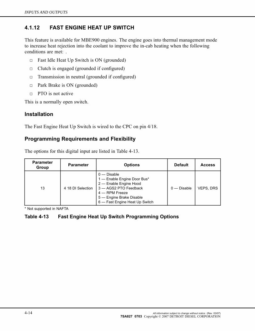
4.1.12 FAST ENGINE HEAT UP SWITCH
This feature is available for MBE900 engines. The engine goes into thermal management modeto increase heat rejection into the coolant to improve the in-cab heating when the followingconditions are met: .
□ Fast Idle Heat Up Switch is ON (grounded)
□ Clutch is engaged (grounded if configured)
□ Transmission in neutral (grounded if configured)
□ Park Brake is ON (grounded)
□ PTO is not active
This is a normally open switch.
Installation
The Fast Engine Heat Up Switch is wired to the CPC on pin 4/18.
Programming Requirements and Flexibility
The options for this digital input are listed in Table 4-13.
ParameterGroup Parameter Options Default Access
13 4 18 DI Selection
0 — Disable1 — Enable Engine Door Bus*2 — Enable Engine Hood3 — AGS2 PTO Feedback4 — RPM Freeze5 — Engine Brake Disable6 — Fast Engine Heat Up Switch
0 — Disable VEPS, DRS
* Not supported in NAFTA
Table 4-13 Fast Engine Heat Up Switch Programming Options
4-14 All information subject to change without notice. (Rev. 03/07)7SA827 0703 Copyright © 2007 DETROIT DIESEL CORPORATION
DDEC VI ELECTRONIC CONTROLS APPLICATION AND INSTALLATION
4.1.13 IDLE VALIDATION 1 & IDLE VALIDATION 2
The Idle Validation Switch consists of two contacts. Idle Validation 1 is normally closed andindicates that the accelerator pedal is in the idle position when the input is grounded. IdleValidation 2 is normally open and indicates that the accelerator pedal is not in the idle positionwhen it is grounded.
NOTE:An Idle Validation Switch is required.
Installation
The Idle Validation 1 Switch is wired to the CPC on pin 1/6. The Idle Validation 2 Switch iswired to the CPC on pin 1/3.
4.1.14 LIMITERS FOR TORQUE, ENGINE SPEED, AND VEHICLE SPEED
These inputs indicate that the engine is being limited to a torque, engine speed or vehicle speed.These limiters are Limiter 0 (LIM0) and Limiter 1 (LIM1).
Installation
Limiter 0 is wired to the CPC on pin 1/11, Limiter 1 on pin 2/11.
Programming Requirements and Flexibility
Refer to section 5.17, “Limiters,” for more information.
All information subject to change without notice. (Rev. 03/07) 4-157SA827 0703 Copyright © 2007 DETROIT DIESEL CORPORATION
INPUTS AND OUTPUTS
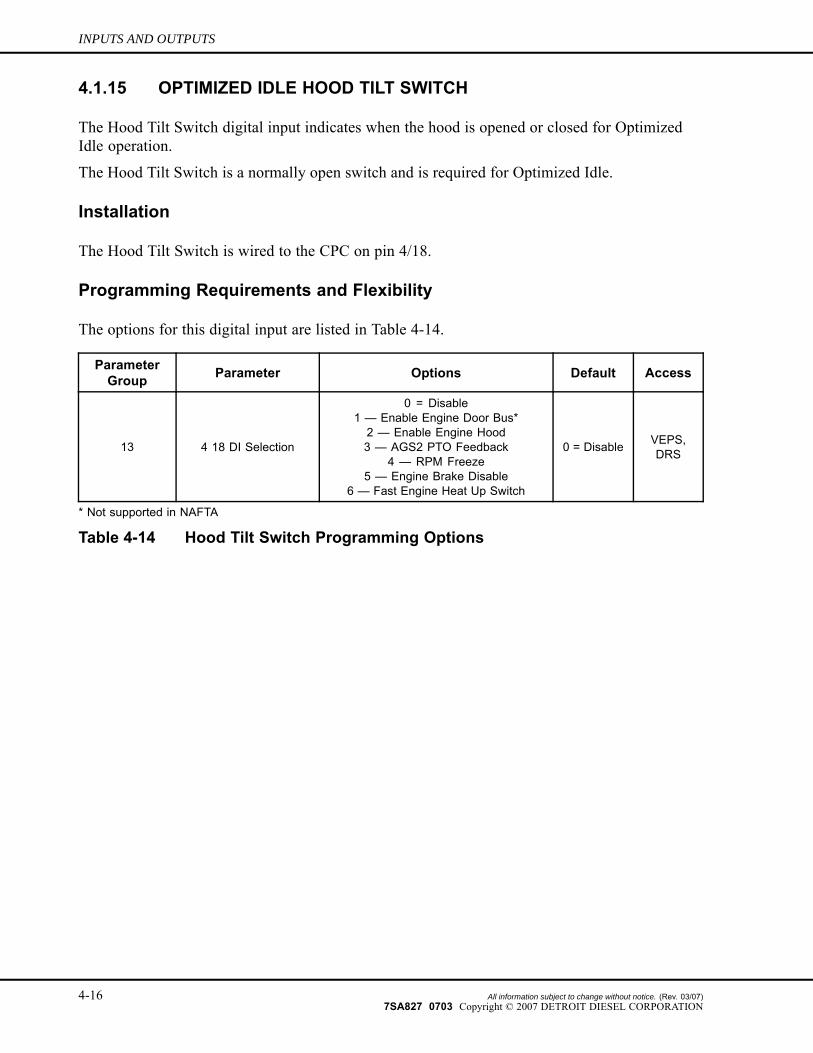
4.1.15 OPTIMIZED IDLE HOOD TILT SWITCH
The Hood Tilt Switch digital input indicates when the hood is opened or closed for OptimizedIdle operation.
The Hood Tilt Switch is a normally open switch and is required for Optimized Idle.
Installation
The Hood Tilt Switch is wired to the CPC on pin 4/18.
Programming Requirements and Flexibility
The options for this digital input are listed in Table 4-14.
ParameterGroup Parameter Options Default Access
13 4 18 DI Selection
0 = Disable1 — Enable Engine Door Bus*2 — Enable Engine Hood3 — AGS2 PTO Feedback
4 — RPM Freeze5 — Engine Brake Disable
6 — Fast Engine Heat Up Switch
0 = Disable VEPS,DRS
* Not supported in NAFTA
Table 4-14 Hood Tilt Switch Programming Options
4-16 All information subject to change without notice. (Rev. 03/07)7SA827 0703 Copyright © 2007 DETROIT DIESEL CORPORATION
DDEC VI ELECTRONIC CONTROLS APPLICATION AND INSTALLATION
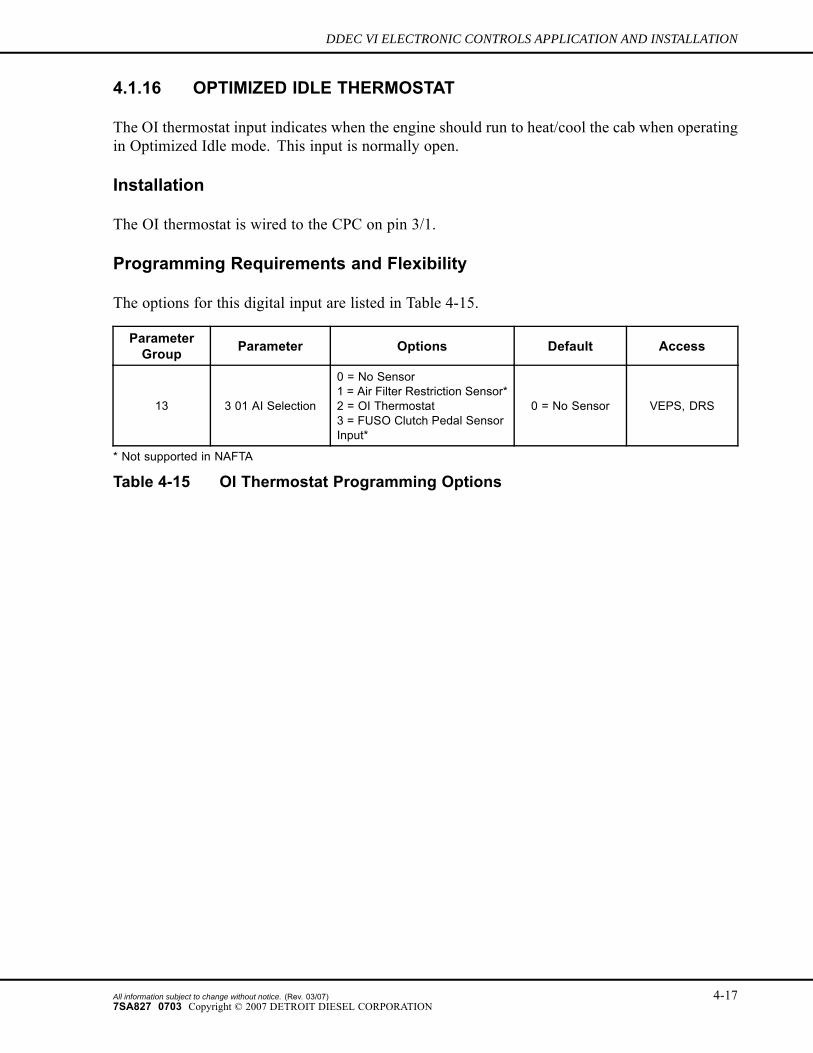
4.1.16 OPTIMIZED IDLE THERMOSTAT
The OI thermostat input indicates when the engine should run to heat/cool the cab when operatingin Optimized Idle mode. This input is normally open.
Installation
The OI thermostat is wired to the CPC on pin 3/1.
Programming Requirements and Flexibility
The options for this digital input are listed in Table 4-15.
ParameterGroup Parameter Options Default Access
13 3 01 AI Selection
0 = No Sensor1 = Air Filter Restriction Sensor*2 = OI Thermostat3 = FUSO Clutch Pedal SensorInput*
0 = No Sensor VEPS, DRS
* Not supported in NAFTA
Table 4-15 OI Thermostat Programming Options
All information subject to change without notice. (Rev. 03/07) 4-177SA827 0703 Copyright © 2007 DETROIT DIESEL CORPORATION
INPUTS AND OUTPUTS
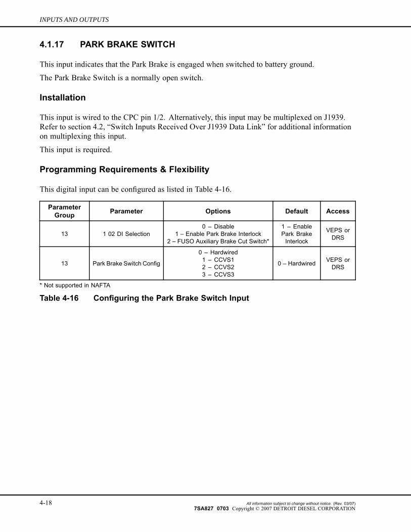
4.1.17 PARK BRAKE SWITCH
This input indicates that the Park Brake is engaged when switched to battery ground.
The Park Brake Switch is a normally open switch.
Installation
This input is wired to the CPC pin 1/2. Alternatively, this input may be multiplexed on J1939.Refer to section 4.2, “Switch Inputs Received Over J1939 Data Link” for additional informationon multiplexing this input.
This input is required.
Programming Requirements & Flexibility
This digital input can be configured as listed in Table 4-16.
ParameterGroup Parameter Options Default Access
13 1 02 DI Selection0 – Disable
1 – Enable Park Brake Interlock2 – FUSO Auxiliary Brake Cut Switch*
1 – EnablePark BrakeInterlock
VEPS orDRS
13 Park Brake Switch Config
0 – Hardwired1 – CCVS12 – CCVS23 – CCVS3
0 – Hardwired VEPS orDRS
* Not supported in NAFTA
Table 4-16 Configuring the Park Brake Switch Input
4-18 All information subject to change without notice. (Rev. 03/07)7SA827 0703 Copyright © 2007 DETROIT DIESEL CORPORATION
DDEC VI ELECTRONIC CONTROLS APPLICATION AND INSTALLATION
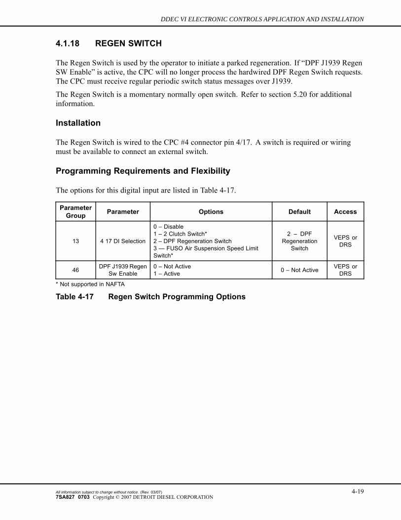
4.1.18 REGEN SWITCH
The Regen Switch is used by the operator to initiate a parked regeneration. If “DPF J1939 RegenSW Enable” is active, the CPC will no longer process the hardwired DPF Regen Switch requests.The CPC must receive regular periodic switch status messages over J1939.
The Regen Switch is a momentary normally open switch. Refer to section 5.20 for additionalinformation.
Installation
The Regen Switch is wired to the CPC #4 connector pin 4/17. A switch is required or wiringmust be available to connect an external switch.
Programming Requirements and Flexibility
The options for this digital input are listed in Table 4-17.
ParameterGroup Parameter Options Default Access
13 4 17 DI Selection
0 – Disable1 – 2 Clutch Switch*2 – DPF Regeneration Switch3 — FUSO Air Suspension Speed LimitSwitch*
2 – DPFRegeneration
Switch
VEPS orDRS
46 DPF J1939 RegenSw Enable
0 – Not Active1 – Active 0 – Not Active VEPS or
DRS
* Not supported in NAFTA
Table 4-17 Regen Switch Programming Options
All information subject to change without notice. (Rev. 03/07) 4-197SA827 0703 Copyright © 2007 DETROIT DIESEL CORPORATION
INPUTS AND OUTPUTS
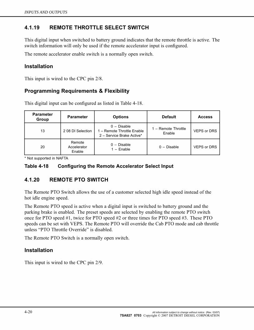
4.1.19 REMOTE THROTTLE SELECT SWITCH
This digital input when switched to battery ground indicates that the remote throttle is active. Theswitch information will only be used if the remote accelerator input is configured.
The remote accelerator enable switch is a normally open switch.
Installation
This input is wired to the CPC pin 2/8.
Programming Requirements & Flexibility
This digital input can be configured as listed in Table 4-18.
ParameterGroup Parameter Options Default Access
13 2 08 DI Selection0 – Disable
1 – Remote Throttle Enable2 – Service Brake Active*
1 – Remote ThrottleEnable VEPS or DRS
20Remote
AcceleratorEnable
0 – Disable1 – Enable 0 – Disable VEPS or DRS
* Not supported in NAFTA
Table 4-18 Configuring the Remote Accelerator Select Input
4.1.20 REMOTE PTO SWITCH
The Remote PTO Switch allows the use of a customer selected high idle speed instead of thehot idle engine speed.
The Remote PTO speed is active when a digital input is switched to battery ground and theparking brake is enabled. The preset speeds are selected by enabling the remote PTO switchonce for PTO speed #1, twice for PTO speed #2 or three times for PTO speed #3. These PTOspeeds can be set with VEPS. The Remote PTO will override the Cab PTO mode and cab throttleunless “PTO Throttle Override” is disabled.
The Remote PTO Switch is a normally open switch.
Installation
This input is wired to the CPC pin 2/9.
4-20 All information subject to change without notice. (Rev. 03/07)7SA827 0703 Copyright © 2007 DETROIT DIESEL CORPORATION
DDEC VI ELECTRONIC CONTROLS APPLICATION AND INSTALLATION
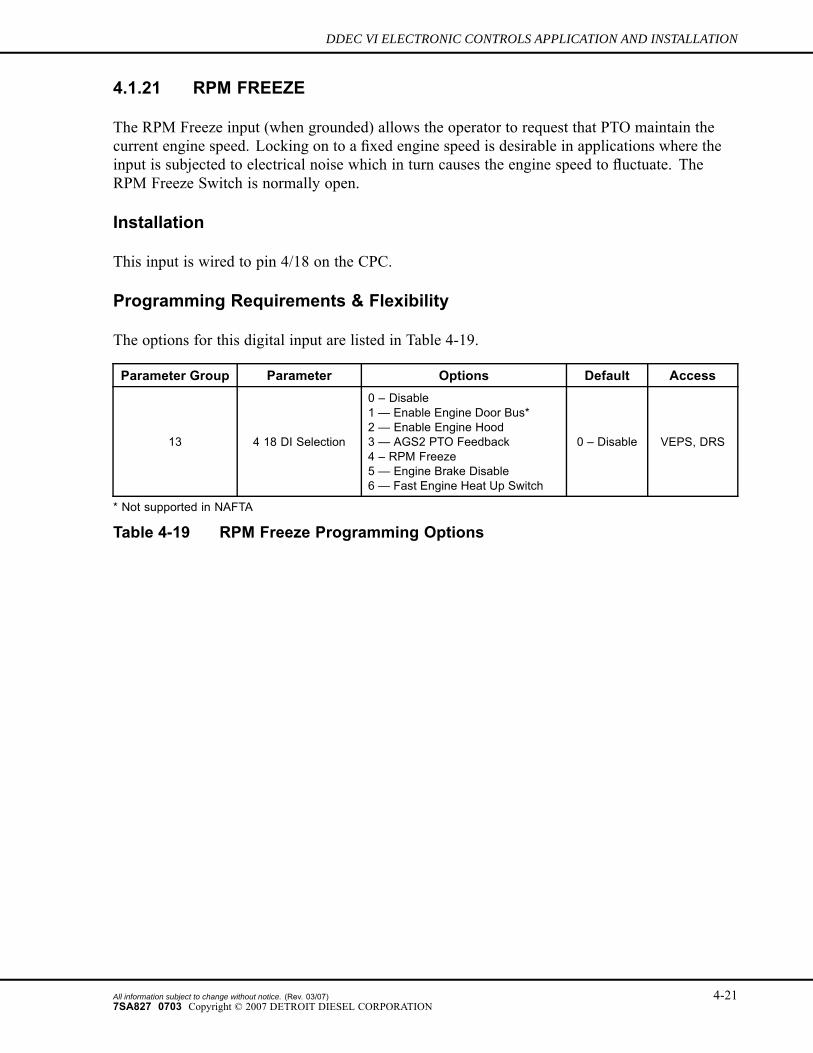
4.1.21 RPM FREEZE
The RPM Freeze input (when grounded) allows the operator to request that PTO maintain thecurrent engine speed. Locking on to a fixed engine speed is desirable in applications where theinput is subjected to electrical noise which in turn causes the engine speed to fluctuate. TheRPM Freeze Switch is normally open.
Installation
This input is wired to pin 4/18 on the CPC.
Programming Requirements & Flexibility
The options for this digital input are listed in Table 4-19.
Parameter Group Parameter Options Default Access
13 4 18 DI Selection
0 – Disable1 — Enable Engine Door Bus*2 — Enable Engine Hood3 — AGS2 PTO Feedback4 – RPM Freeze5 — Engine Brake Disable6 — Fast Engine Heat Up Switch
0 – Disable VEPS, DRS
* Not supported in NAFTA
Table 4-19 RPM Freeze Programming Options
All information subject to change without notice. (Rev. 03/07) 4-217SA827 0703 Copyright © 2007 DETROIT DIESEL CORPORATION
INPUTS AND OUTPUTS
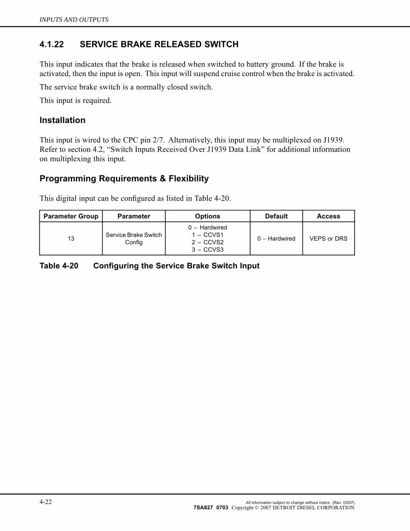
4.1.22 SERVICE BRAKE RELEASED SWITCH
This input indicates that the brake is released when switched to battery ground. If the brake isactivated, then the input is open. This input will suspend cruise control when the brake is activated.
The service brake switch is a normally closed switch.
This input is required.
Installation
This input is wired to the CPC pin 2/7. Alternatively, this input may be multiplexed on J1939.Refer to section 4.2, “Switch Inputs Received Over J1939 Data Link” for additional informationon multiplexing this input.
Programming Requirements & Flexibility
This digital input can be configured as listed in Table 4-20.
Parameter Group Parameter Options Default Access
13 Service Brake SwitchConfig
0 – Hardwired1 – CCVS12 – CCVS23 – CCVS3
0 – Hardwired VEPS or DRS
Table 4-20 Configuring the Service Brake Switch Input
4-22 All information subject to change without notice. (Rev. 03/07)7SA827 0703 Copyright © 2007 DETROIT DIESEL CORPORATION
DDEC VI ELECTRONIC CONTROLS APPLICATION AND INSTALLATION
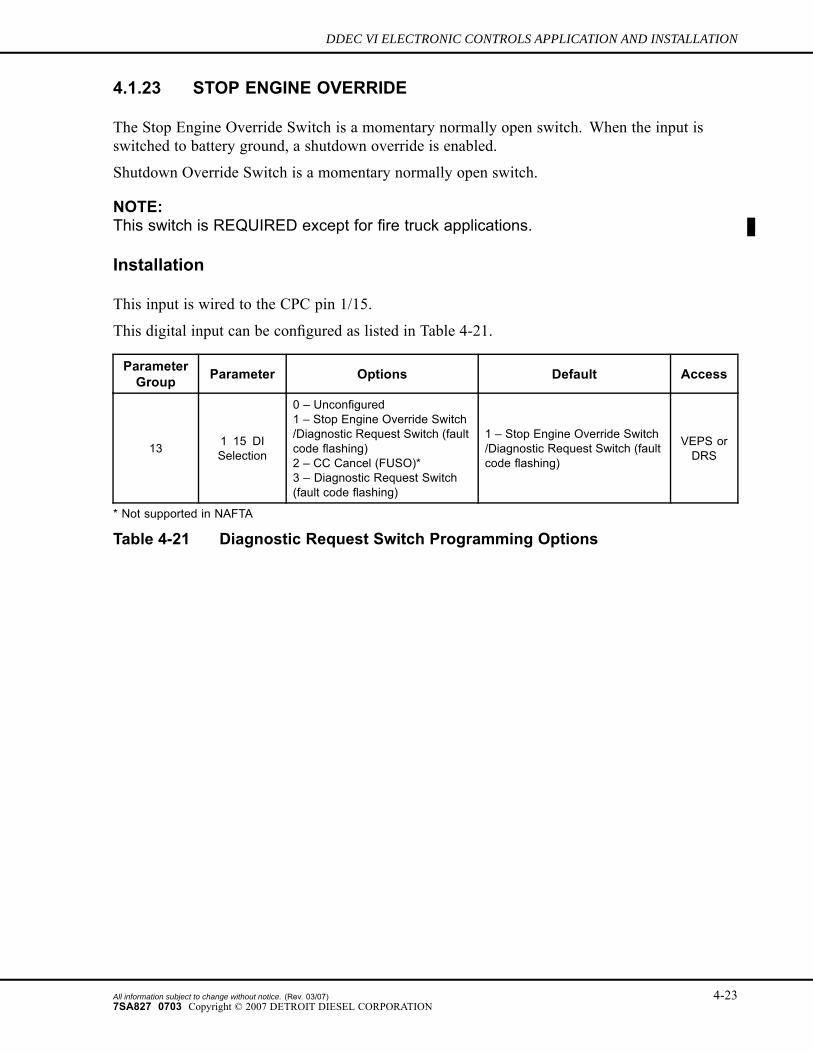
4.1.23 STOP ENGINE OVERRIDE
The Stop Engine Override Switch is a momentary normally open switch. When the input isswitched to battery ground, a shutdown override is enabled.
Shutdown Override Switch is a momentary normally open switch.
NOTE:This switch is REQUIRED except for fire truck applications.
Installation
This input is wired to the CPC pin 1/15.
This digital input can be configured as listed in Table 4-21.
ParameterGroup Parameter Options Default Access
13 1 15 DISelection
0 – Unconfigured1 – Stop Engine Override Switch/Diagnostic Request Switch (faultcode flashing)2 – CC Cancel (FUSO)*3 – Diagnostic Request Switch(fault code flashing)
1 – Stop Engine Override Switch/Diagnostic Request Switch (faultcode flashing)
VEPS orDRS
* Not supported in NAFTA
Table 4-21 Diagnostic Request Switch Programming Options
All information subject to change without notice. (Rev. 03/07) 4-237SA827 0703 Copyright © 2007 DETROIT DIESEL CORPORATION
INPUTS AND OUTPUTS
4.1.24 THROTTLE INHIBIT
If the Throttle Inhibit Switch is switched to battery ground, the engine will not respond to thefoot pedal or remote throttle.
If the Throttle Inhibit Switch is grounded while the vehicle speed is greater than X mph, thethrottle inhibit function will be disabled until the switch is validated again.
The Throttle Inhibit Switch is a normally open switch.
Installation
The Throttle Inhibit Switch is wired to the CPC on pin 1/17.
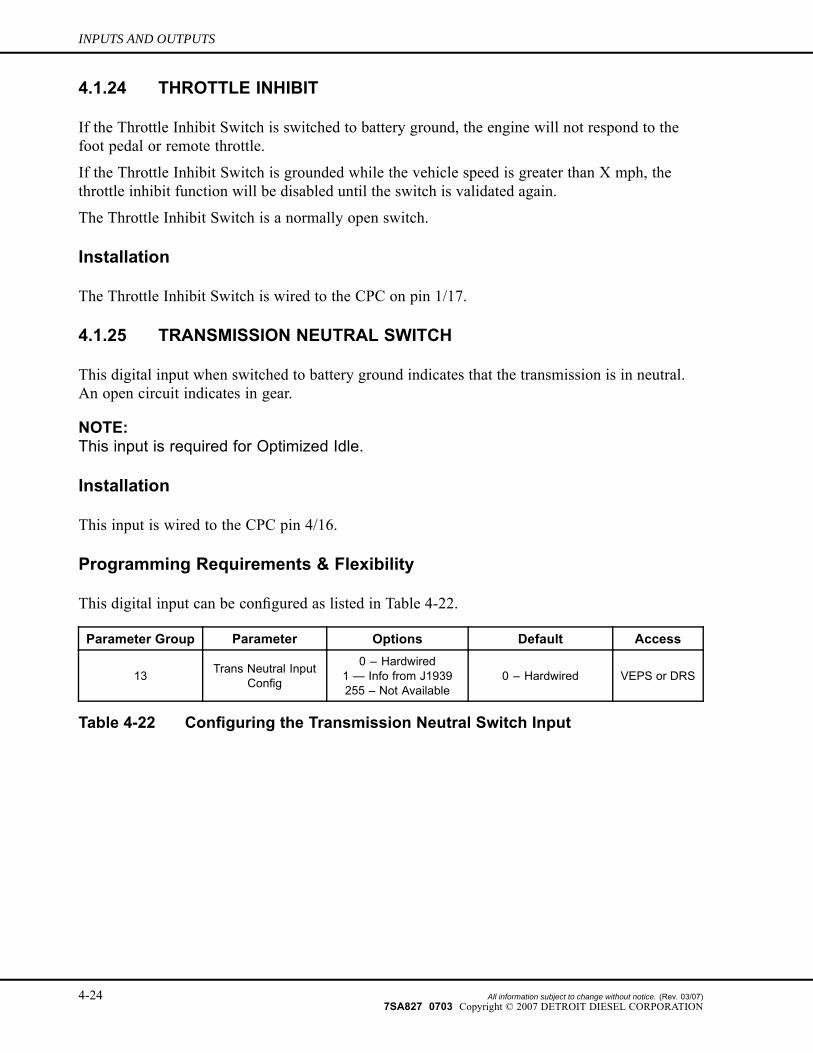
4.1.25 TRANSMISSION NEUTRAL SWITCH
This digital input when switched to battery ground indicates that the transmission is in neutral.An open circuit indicates in gear.
NOTE:This input is required for Optimized Idle.
Installation
This input is wired to the CPC pin 4/16.
Programming Requirements & Flexibility
This digital input can be configured as listed in Table 4-22.
Parameter Group Parameter Options Default Access
13 Trans Neutral InputConfig
0 – Hardwired1 — Info from J1939255 – Not Available
0 – Hardwired VEPS or DRS
Table 4-22 Configuring the Transmission Neutral Switch Input
4-24 All information subject to change without notice. (Rev. 03/07)7SA827 0703 Copyright © 2007 DETROIT DIESEL CORPORATION
DDEC VI ELECTRONIC CONTROLS APPLICATION AND INSTALLATION
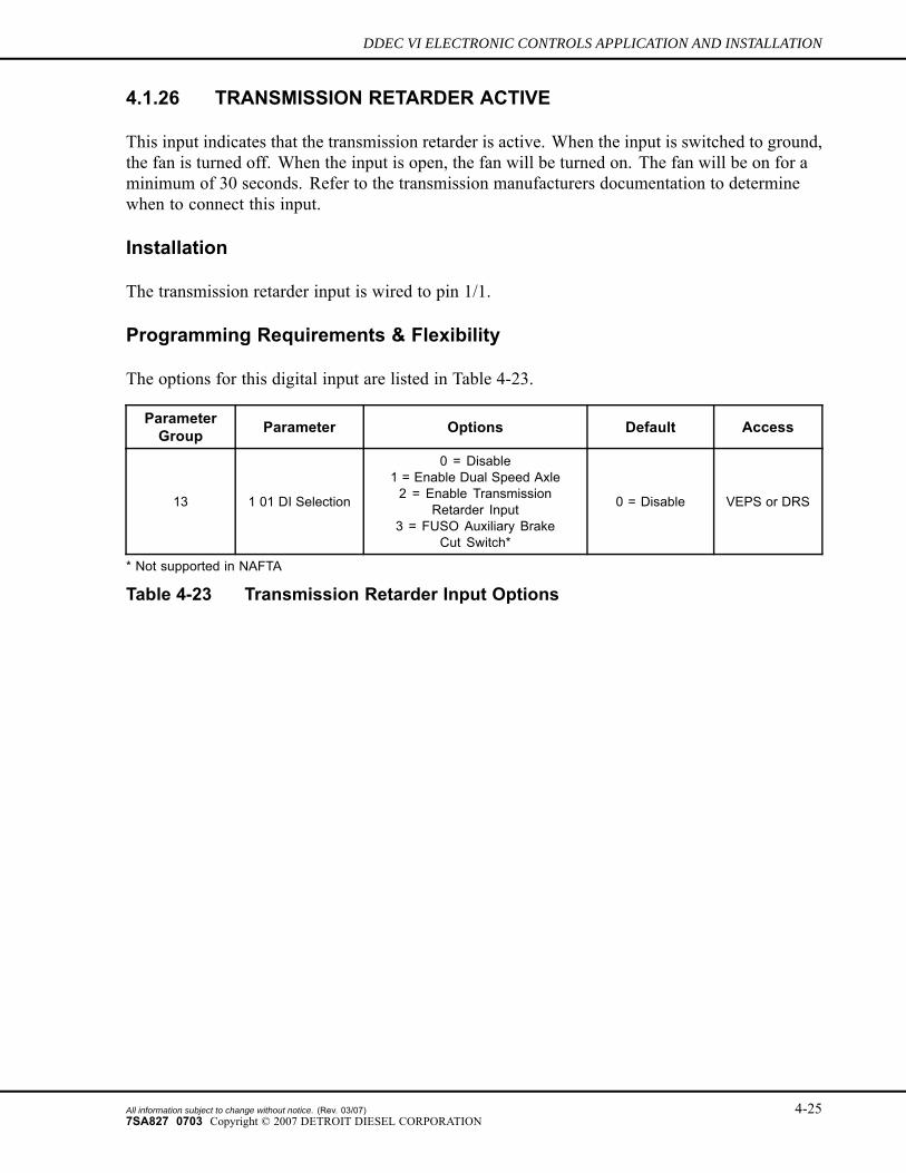
4.1.26 TRANSMISSION RETARDER ACTIVE
This input indicates that the transmission retarder is active. When the input is switched to ground,the fan is turned off. When the input is open, the fan will be turned on. The fan will be on for aminimum of 30 seconds. Refer to the transmission manufacturers documentation to determinewhen to connect this input.
Installation
The transmission retarder input is wired to pin 1/1.
Programming Requirements & Flexibility
The options for this digital input are listed in Table 4-23.
ParameterGroup Parameter Options Default Access
13 1 01 DI Selection
0 = Disable1 = Enable Dual Speed Axle2 = Enable Transmission
Retarder Input3 = FUSO Auxiliary Brake
Cut Switch*
0 = Disable VEPS or DRS
* Not supported in NAFTA
Table 4-23 Transmission Retarder Input Options
All information subject to change without notice. (Rev. 03/07) 4-257SA827 0703 Copyright © 2007 DETROIT DIESEL CORPORATION

INPUTS AND OUTPUTS
THIS PAGE INTENTIONALLY LEFT BLANK
4-26 All information subject to change without notice. (Rev. 03/07)7SA827 0703 Copyright © 2007 DETROIT DIESEL CORPORATION
DDEC VI ELECTRONIC CONTROLS APPLICATION AND INSTALLATION
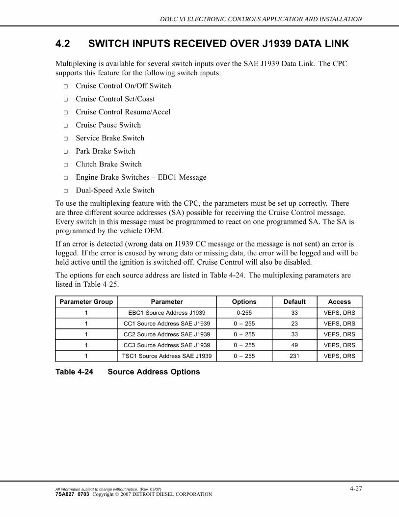
4.2 SWITCH INPUTS RECEIVED OVER J1939 DATA LINK
Multiplexing is available for several switch inputs over the SAE J1939 Data Link. The CPCsupports this feature for the following switch inputs:
□ Cruise Control On/Off Switch
□ Cruise Control Set/Coast
□ Cruise Control Resume/Accel
□ Cruise Pause Switch
□ Service Brake Switch
□ Park Brake Switch
□ Clutch Brake Switch
□ Engine Brake Switches – EBC1 Message
□ Dual-Speed Axle Switch
To use the multiplexing feature with the CPC, the parameters must be set up correctly. Thereare three different source addresses (SA) possible for receiving the Cruise Control message.Every switch in this message must be programmed to react on one programmed SA. The SA isprogrammed by the vehicle OEM.
If an error is detected (wrong data on J1939 CC message or the message is not sent) an error islogged. If the error is caused by wrong data or missing data, the error will be logged and will beheld active until the ignition is switched off. Cruise Control will also be disabled.
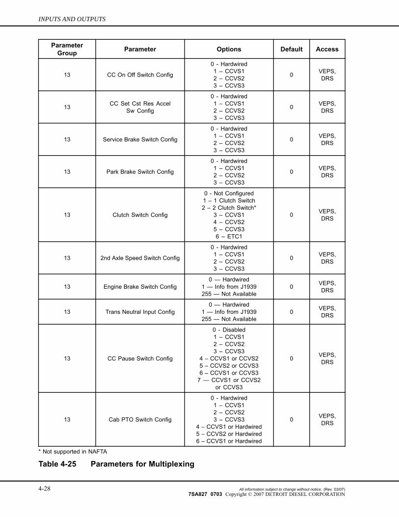
The options for each source address are listed in Table 4-24. The multiplexing parameters arelisted in Table 4-25.
Parameter Group Parameter Options Default Access1 EBC1 Source Address J1939 0-255 33 VEPS, DRS
1 CC1 Source Address SAE J1939 0 – 255 23 VEPS, DRS
1 CC2 Source Address SAE J1939 0 – 255 33 VEPS, DRS
1 CC3 Source Address SAE J1939 0 – 255 49 VEPS, DRS
1 TSC1 Source Address SAE J1939 0 – 255 231 VEPS, DRS
Table 4-24 Source Address Options
All information subject to change without notice. (Rev. 03/07) 4-277SA827 0703 Copyright © 2007 DETROIT DIESEL CORPORATION
INPUTS AND OUTPUTS
ParameterGroup Parameter Options Default Access
13 CC On Off Switch Config
0 - Hardwired1 – CCVS12 – CCVS23 – CCVS3
0 VEPS,DRS
13 CC Set Cst Res AccelSw Config
0 - Hardwired1 – CCVS12 – CCVS23 – CCVS3
0 VEPS,DRS
13 Service Brake Switch Config
0 - Hardwired1 – CCVS12 – CCVS23 – CCVS3
0 VEPS,DRS
13 Park Brake Switch Config
0 - Hardwired1 – CCVS12 – CCVS23 – CCVS3
0 VEPS,DRS
13 Clutch Switch Config
0 - Not Configured1 – 1 Clutch Switch2 – 2 Clutch Switch*
3 – CCVS14 – CCVS25 – CCVS36 – ETC1
0 VEPS,DRS
13 2nd Axle Speed Switch Config
0 - Hardwired1 – CCVS12 – CCVS23 – CCVS3
0 VEPS,DRS
13 Engine Brake Switch Config0 — Hardwired
1 — Info from J1939255 — Not Available
0 VEPS,DRS
13 Trans Neutral Input Config0 — Hardwired
1 — Info from J1939255 — Not Available
0 VEPS,DRS
13 CC Pause Switch Config
0 - Disabled1 – CCVS12 – CCVS23 – CCVS3
4 – CCVS1 or CCVS25 – CCVS2 or CCVS36 – CCVS1 or CCVS37 — CCVS1 or CCVS2
or CCVS3
0 VEPS,DRS
13 Cab PTO Switch Config
0 - Hardwired1 – CCVS12 – CCVS23 – CCVS3
4 – CCVS1 or Hardwired5 – CCVS2 or Hardwired6 – CCVS1 or Hardwired
0 VEPS,DRS
* Not supported in NAFTA
Table 4-25 Parameters for Multiplexing
4-28 All information subject to change without notice. (Rev. 03/07)7SA827 0703 Copyright © 2007 DETROIT DIESEL CORPORATION
DDEC VI ELECTRONIC CONTROLS APPLICATION AND INSTALLATION
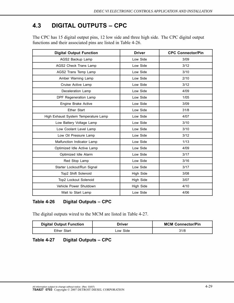
4.3 DIGITAL OUTPUTS – CPC
The CPC has 15 digital output pins, 12 low side and three high side. The CPC digital outputfunctions and their associated pins are listed in Table 4-26.
Digital Output Function Driver CPC Connector/PinAGS2 Backup Lamp Low Side 3/09
AGS2 Check Trans Lamp Low Side 3/12
AGS2 Trans Temp Lamp Low Side 3/10
Amber Warning Lamp Low Side 2/10
Cruise Active Lamp Low Side 3/12
Deceleration Lamp Low Side 4/09
DPF Regeneration Lamp Low Side 1/05
Engine Brake Active Low Side 3/09
Ether Start Low Side 31/8
High Exhaust System Temperature Lamp Low Side 4/07
Low Battery Voltage Lamp Low Side 3/10
Low Coolant Level Lamp Low Side 3/10
Low Oil Pressure Lamp Low Side 3/12
Malfunction Indicator Lamp Low Side 1/13
Optimized Idle Active Lamp Low Side 4/09
Optimized Idle Alarm Low Side 3/17
Red Stop Lamp Low Side 3/16
Starter Lockout/Run Signal Low Side 3/17
Top2 Shift Solenoid High Side 3/08
Top2 Lockout Solenoid High Side 3/07
Vehicle Power Shutdown High Side 4/10
Wait to Start Lamp Low Side 4/06
Table 4-26 Digital Outputs – CPC
The digital outputs wired to the MCM are listed in Table 4-27.
Digital Output Function Driver MCM Connector/PinEther Start Low Side 31/8
Table 4-27 Digital Outputs – CPC
All information subject to change without notice. (Rev. 03/07) 4-297SA827 0703 Copyright © 2007 DETROIT DIESEL CORPORATION
INPUTS AND OUTPUTS
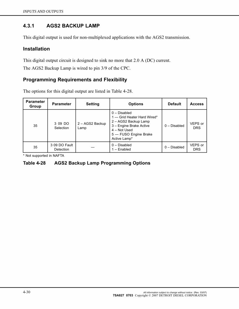
4.3.1 AGS2 BACKUP LAMP
This digital output is used for non-multiplexed applications with the AGS2 transmission.
Installation
This digital output circuit is designed to sink no more that 2.0 A (DC) current.
The AGS2 Backup Lamp is wired to pin 3/9 of the CPC.
Programming Requirements and Flexibility
The options for this digital output are listed in Table 4-28.
ParameterGroup Parameter Setting Options Default Access
35 3 09 DOSelection
2 – AGS2 BackupLamp
0 – Disabled1 — Grid Heater Hard Wired*2 – AGS2 Backup Lamp3 – Engine Brake Active4 – Not Used5 — FUSO Engine BrakeActive Lamp*
0 – Disabled VEPS orDRS
35 3 09 DO FaultDetection — 0 – Disabled
1 – Enabled 0 – Disabled VEPS orDRS
* Not supported in NAFTA
Table 4-28 AGS2 Backup Lamp Programming Options
4-30 All information subject to change without notice. (Rev. 03/07)7SA827 0703 Copyright © 2007 DETROIT DIESEL CORPORATION
DDEC VI ELECTRONIC CONTROLS APPLICATION AND INSTALLATION
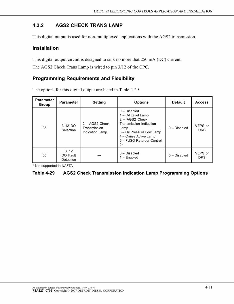
4.3.2 AGS2 CHECK TRANS LAMP
This digital output is used for non-multiplexed applications with the AGS2 transmission.
Installation
This digital output circuit is designed to sink no more that 250 mA (DC) current.
The AGS2 Check Trans Lamp is wired to pin 3/12 of the CPC.
Programming Requirements and Flexibility
The options for this digital output are listed in Table 4-29.
ParameterGroup Parameter Setting Options Default Access
35 3 12 DOSelection
2 – AGS2 CheckTransmissionIndication Lamp
0 – Disabled1 – Oil Level Lamp2 – AGS2 CheckTransmission IndicationLamp3 – Oil Pressure Low Lamp4 – Cruise Active Lamp5 – FUSO Retarder Control2*
0 – Disabled VEPS orDRS
353 12
DO FaultDetection
— 0 – Disabled1 – Enabled 0 – Disabled VEPS or
DRS
* Not supported in NAFTA
Table 4-29 AGS2 Check Transmission Indication Lamp Programming Options
All information subject to change without notice. (Rev. 03/07) 4-317SA827 0703 Copyright © 2007 DETROIT DIESEL CORPORATION
INPUTS AND OUTPUTS
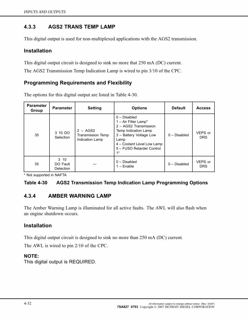
4.3.3 AGS2 TRANS TEMP LAMP
This digital output is used for non-multiplexed applications with the AGS2 transmission.
Installation
This digital output circuit is designed to sink no more that 250 mA (DC) current.
The AGS2 Transmission Temp Indication Lamp is wired to pin 3/10 of the CPC.
Programming Requirements and Flexibility
The options for this digital output are listed in Table 4-30.
ParameterGroup Parameter Setting Options Default Access
35 3 10 DOSelection
2 – AGS2Transmission TempIndication Lamp
0 – Disabled1 – Air Filter Lamp*2 – AGS2 TransmissionTemp Indication Lamp3 – Battery Voltage LowLamp4 – Coolant Level Low Lamp5 – FUSO Retarder Control1*
0 – Disabled VEPS orDRS
353 10
DO FaultDetection
— 0 – Disabled1 – Enable 0 – Disabled VEPS or
DRS
* Not supported in NAFTA
Table 4-30 AGS2 Transmission Temp Indication Lamp Programming Options
4.3.4 AMBER WARNING LAMP
The Amber Warning Lamp is illuminated for all active faults. The AWL will also flash whenan engine shutdown occurs.
Installation
This digital output circuit is designed to sink no more than 250 mA (DC) current.
The AWL is wired to pin 2/10 of the CPC.
NOTE:This digital output is REQUIRED.
4-32 All information subject to change without notice. (Rev. 03/07)7SA827 0703 Copyright © 2007 DETROIT DIESEL CORPORATION
DDEC VI ELECTRONIC CONTROLS APPLICATION AND INSTALLATION
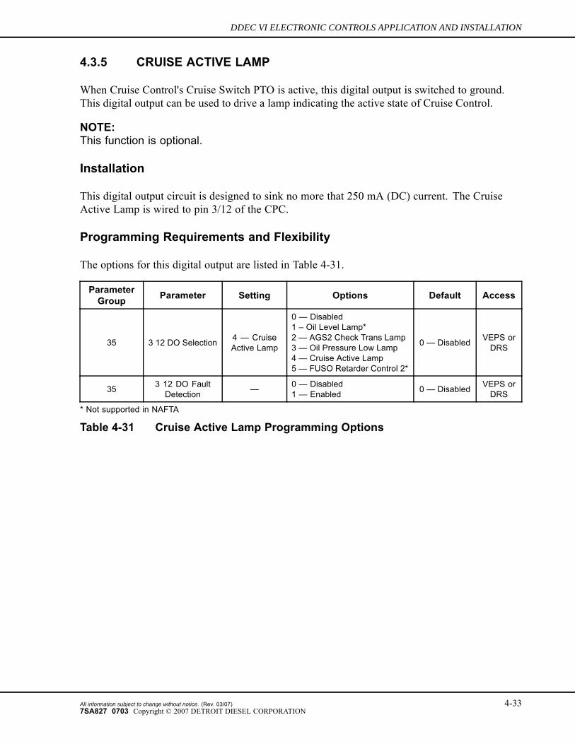
4.3.5 CRUISE ACTIVE LAMP
When Cruise Control's Cruise Switch PTO is active, this digital output is switched to ground.This digital output can be used to drive a lamp indicating the active state of Cruise Control.
NOTE:This function is optional.
Installation
This digital output circuit is designed to sink no more that 250 mA (DC) current. The CruiseActive Lamp is wired to pin 3/12 of the CPC.
Programming Requirements and Flexibility
The options for this digital output are listed in Table 4-31.
ParameterGroup Parameter Setting Options Default Access
35 3 12 DO Selection 4 — CruiseActive Lamp
0 — Disabled1 – Oil Level Lamp*2 — AGS2 Check Trans Lamp3 — Oil Pressure Low Lamp4 — Cruise Active Lamp5 — FUSO Retarder Control 2*
0 — Disabled VEPS orDRS
35 3 12 DO FaultDetection — 0 — Disabled
1 — Enabled 0 — Disabled VEPS orDRS
* Not supported in NAFTA
Table 4-31 Cruise Active Lamp Programming Options
All information subject to change without notice. (Rev. 03/07) 4-337SA827 0703 Copyright © 2007 DETROIT DIESEL CORPORATION
INPUTS AND OUTPUTS
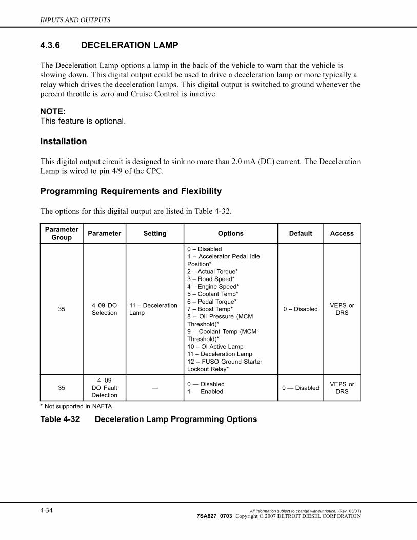
4.3.6 DECELERATION LAMP
The Deceleration Lamp options a lamp in the back of the vehicle to warn that the vehicle isslowing down. This digital output could be used to drive a deceleration lamp or more typically arelay which drives the deceleration lamps. This digital output is switched to ground whenever thepercent throttle is zero and Cruise Control is inactive.
NOTE:This feature is optional.
Installation
This digital output circuit is designed to sink no more than 2.0 mA (DC) current. The DecelerationLamp is wired to pin 4/9 of the CPC.
Programming Requirements and Flexibility
The options for this digital output are listed in Table 4-32.
ParameterGroup Parameter Setting Options Default Access
35 4 09 DOSelection
11 – DecelerationLamp
0 – Disabled1 – Accelerator Pedal IdlePosition*2 – Actual Torque*3 – Road Speed*4 – Engine Speed*5 – Coolant Temp*6 – Pedal Torque*7 – Boost Temp*8 – Oil Pressure (MCMThreshold)*9 – Coolant Temp (MCMThreshold)*10 – OI Active Lamp11 – Deceleration Lamp12 – FUSO Ground StarterLockout Relay*
0 – Disabled VEPS orDRS
354 09
DO FaultDetection
— 0 — Disabled1 — Enabled 0 — Disabled VEPS or
DRS
* Not supported in NAFTA
Table 4-32 Deceleration Lamp Programming Options
4-34 All information subject to change without notice. (Rev. 03/07)7SA827 0703 Copyright © 2007 DETROIT DIESEL CORPORATION
DDEC VI ELECTRONIC CONTROLS APPLICATION AND INSTALLATION
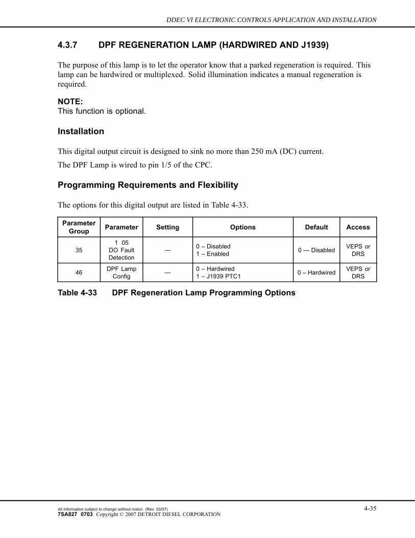
4.3.7 DPF REGENERATION LAMP (HARDWIRED AND J1939)
The purpose of this lamp is to let the operator know that a parked regeneration is required. Thislamp can be hardwired or multiplexed. Solid illumination indicates a manual regeneration isrequired.
NOTE:This function is optional.
Installation
This digital output circuit is designed to sink no more than 250 mA (DC) current.
The DPF Lamp is wired to pin 1/5 of the CPC.
Programming Requirements and Flexibility
The options for this digital output are listed in Table 4-33.
ParameterGroup Parameter Setting Options Default Access
351 05
DO FaultDetection
— 0 – Disabled1 – Enabled 0 — Disabled VEPS or
DRS
46 DPF LampConfig — 0 – Hardwired
1 – J1939 PTC1 0 – Hardwired VEPS orDRS
Table 4-33 DPF Regeneration Lamp Programming Options
All information subject to change without notice. (Rev. 03/07) 4-357SA827 0703 Copyright © 2007 DETROIT DIESEL CORPORATION
INPUTS AND OUTPUTS
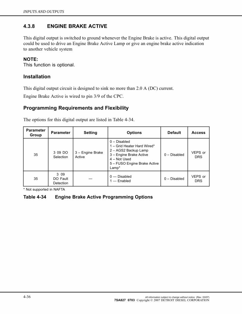
4.3.8 ENGINE BRAKE ACTIVE
This digital output is switched to ground whenever the Engine Brake is active. This digital outputcould be used to drive an Engine Brake Active Lamp or give an engine brake active indicationto another vehicle system
NOTE:This function is optional.
Installation
This digital output circuit is designed to sink no more than 2.0 A (DC) current.
Engine Brake Active is wired to pin 3/9 of the CPC.
Programming Requirements and Flexibility
The options for this digital output are listed in Table 4-34.
ParameterGroup Parameter Setting Options Default Access
35 3 09 DOSelection
3 – Engine BrakeActive
0 – Disabled1 – Grid Heater Hard Wired*2 – AGS2 Backup Lamp3 – Engine Brake Active4 – Not Used5 – FUSO Engine Brake ActiveLamp*
0 – Disabled VEPS orDRS
353 09
DO FaultDetection
— 0 — Disabled1 — Enabled 0 – Disabled VEPS or
DRS
* Not supported in NAFTA
Table 4-34 Engine Brake Active Programming Options
4-36 All information subject to change without notice. (Rev. 03/07)7SA827 0703 Copyright © 2007 DETROIT DIESEL CORPORATION
DDEC VI ELECTRONIC CONTROLS APPLICATION AND INSTALLATION
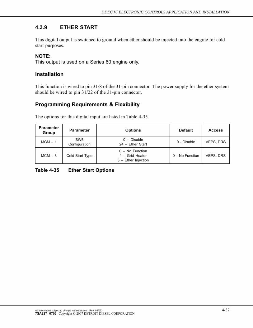
4.3.9 ETHER START
This digital output is switched to ground when ether should be injected into the engine for coldstart purposes.
NOTE:This output is used on a Series 60 engine only.
Installation
This function is wired to pin 31/8 of the 31-pin connector. The power supply for the ether systemshould be wired to pin 31/22 of the 31-pin connector.
Programming Requirements & Flexibility
The options for this digital input are listed in Table 4-35.
ParameterGroup Parameter Options Default Access
MCM – 1 SW6Configuration
0 – Disable24 – Ether Start 0 - Disable VEPS, DRS
MCM – 8 Cold Start Type0 – No Function1 – Grid Heater3 – Ether Injection
0 – No Function VEPS, DRS
Table 4-35 Ether Start Options
All information subject to change without notice. (Rev. 03/07) 4-377SA827 0703 Copyright © 2007 DETROIT DIESEL CORPORATION
INPUTS AND OUTPUTS
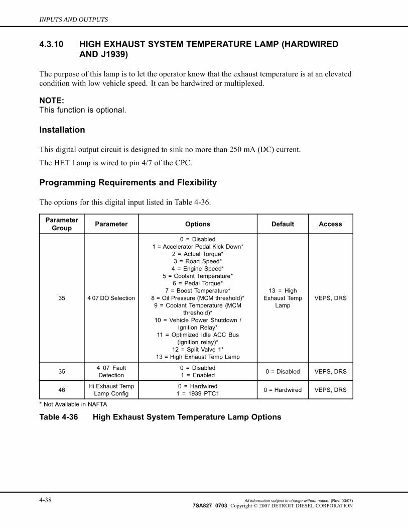
4.3.10 HIGH EXHAUST SYSTEM TEMPERATURE LAMP (HARDWIREDAND J1939)
The purpose of this lamp is to let the operator know that the exhaust temperature is at an elevatedcondition with low vehicle speed. It can be hardwired or multiplexed.
NOTE:This function is optional.
Installation
This digital output circuit is designed to sink no more than 250 mA (DC) current.
The HET Lamp is wired to pin 4/7 of the CPC.
Programming Requirements and Flexibility
The options for this digital input listed in Table 4-36.
ParameterGroup Parameter Options Default Access
35 4 07 DO Selection
0 = Disabled1 = Accelerator Pedal Kick Down*
2 = Actual Torque*3 = Road Speed*4 = Engine Speed*
5 = Coolant Temperature*6 = Pedal Torque*
7 = Boost Temperature*8 = Oil Pressure (MCM threshold)*9 = Coolant Temperature (MCM
threshold)*10 = Vehicle Power Shutdown /
Ignition Relay*11 = Optimized Idle ACC Bus
(ignition relay)*12 = Split Valve 1*
13 = High Exhaust Temp Lamp
13 = HighExhaust Temp
LampVEPS, DRS
35 4 07 FaultDetection
0 = Disabled1 = Enabled 0 = Disabled VEPS, DRS
46 Hi Exhaust TempLamp Config
0 = Hardwired1 = 1939 PTC1 0 = Hardwired VEPS, DRS
* Not Available in NAFTA
Table 4-36 High Exhaust System Temperature Lamp Options
4-38 All information subject to change without notice. (Rev. 03/07)7SA827 0703 Copyright © 2007 DETROIT DIESEL CORPORATION
DDEC VI ELECTRONIC CONTROLS APPLICATION AND INSTALLATION
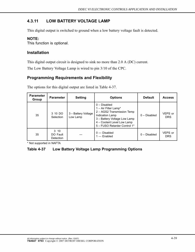
4.3.11 LOW BATTERY VOLTAGE LAMP
This digital output is switched to ground when a low battery voltage fault is detected.
NOTE:This function is optional.
Installation
This digital output circuit is designed to sink no more than 2.0 A (DC) current.
The Low Battery Voltage Lamp is wired to pin 3/10 of the CPC.
Programming Requirements and Flexibility
The options for this digital output are listed in Table 4-37.
ParameterGroup Parameter Setting Options Default Access
35 3 10 DOSelection
3 – Battery VoltageLow Lamp
0 – Disabled1 – Air Filter Lamp*2 – AGS2 Transmission TempIndication Lamp3 – Battery Voltage Low Lamp4 – Coolant Level Low Lamp5 – FUSO Retarder Control 1*
0 – Disabled VEPS orDRS
353 10
DO FaultDetection
— 0 — Disabled1 — Enabled 0 – Disabled VEPS or
DRS
* Not supported in NAFTA
Table 4-37 Low Battery Voltage Lamp Programming Options
All information subject to change without notice. (Rev. 03/07) 4-397SA827 0703 Copyright © 2007 DETROIT DIESEL CORPORATION
INPUTS AND OUTPUTS
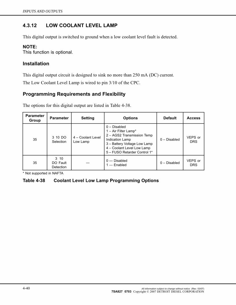
4.3.12 LOW COOLANT LEVEL LAMP
This digital output is switched to ground when a low coolant level fault is detected.
NOTE:This function is optional.
Installation
This digital output circuit is designed to sink no more than 250 mA (DC) current.
The Low Coolant Level Lamp is wired to pin 3/10 of the CPC.
Programming Requirements and Flexibility
The options for this digital output are listed in Table 4-38.
ParameterGroup Parameter Setting Options Default Access
35 3 10 DOSelection
4 – Coolant LevelLow Lamp
0 – Disabled1 – Air Filter Lamp*2 – AGS2 Transmission TempIndication Lamp3 – Battery Voltage Low Lamp4 – Coolant Level Low Lamp5 – FUSO Retarder Control 1*
0 – Disabled VEPS orDRS
353 10
DO FaultDetection
— 0 — Disabled1 — Enabled 0 – Disabled VEPS or
DRS
* Not supported in NAFTA
Table 4-38 Coolant Level Low Lamp Programming Options
4-40 All information subject to change without notice. (Rev. 03/07)7SA827 0703 Copyright © 2007 DETROIT DIESEL CORPORATION
DDEC VI ELECTRONIC CONTROLS APPLICATION AND INSTALLATION
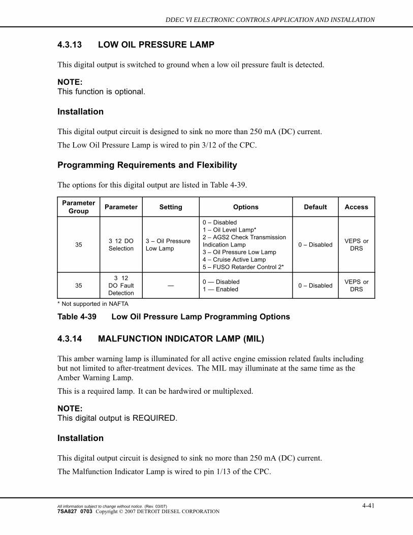
4.3.13 LOW OIL PRESSURE LAMP
This digital output is switched to ground when a low oil pressure fault is detected.
NOTE:This function is optional.
Installation
This digital output circuit is designed to sink no more than 250 mA (DC) current.
The Low Oil Pressure Lamp is wired to pin 3/12 of the CPC.
Programming Requirements and Flexibility
The options for this digital output are listed in Table 4-39.
ParameterGroup Parameter Setting Options Default Access
35 3 12 DOSelection
3 – Oil PressureLow Lamp
0 – Disabled1 – Oil Level Lamp*2 – AGS2 Check TransmissionIndication Lamp3 – Oil Pressure Low Lamp4 – Cruise Active Lamp5 – FUSO Retarder Control 2*
0 – Disabled VEPS orDRS
353 12
DO FaultDetection
— 0 — Disabled1 — Enabled 0 – Disabled VEPS or
DRS
* Not supported in NAFTA
Table 4-39 Low Oil Pressure Lamp Programming Options
4.3.14 MALFUNCTION INDICATOR LAMP (MIL)
This amber warning lamp is illuminated for all active engine emission related faults includingbut not limited to after-treatment devices. The MIL may illuminate at the same time as theAmber Warning Lamp.
This is a required lamp. It can be hardwired or multiplexed.
NOTE:This digital output is REQUIRED.
Installation
This digital output circuit is designed to sink no more than 250 mA (DC) current.
The Malfunction Indicator Lamp is wired to pin 1/13 of the CPC.
All information subject to change without notice. (Rev. 03/07) 4-417SA827 0703 Copyright © 2007 DETROIT DIESEL CORPORATION
INPUTS AND OUTPUTS
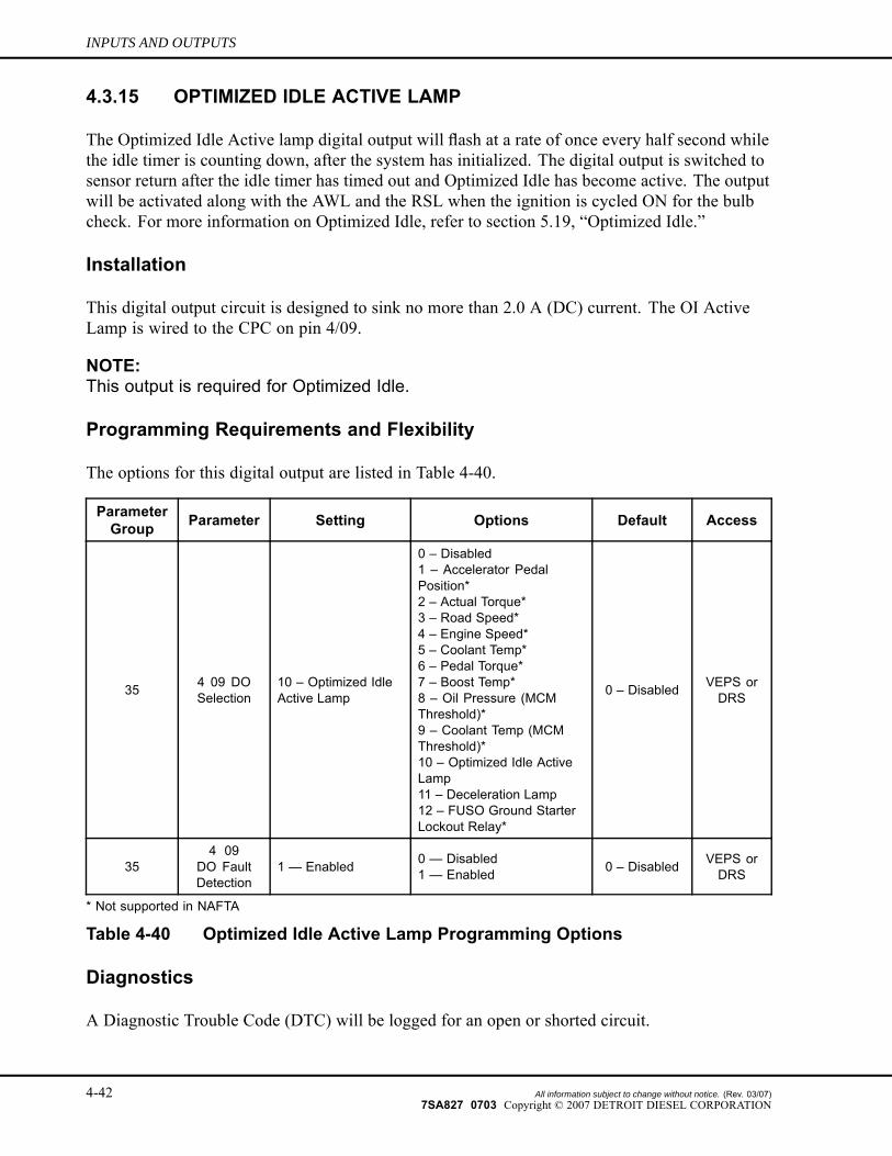
4.3.15 OPTIMIZED IDLE ACTIVE LAMP
The Optimized Idle Active lamp digital output will flash at a rate of once every half second whilethe idle timer is counting down, after the system has initialized. The digital output is switched tosensor return after the idle timer has timed out and Optimized Idle has become active. The outputwill be activated along with the AWL and the RSL when the ignition is cycled ON for the bulbcheck. For more information on Optimized Idle, refer to section 5.19, “Optimized Idle.”
Installation
This digital output circuit is designed to sink no more than 2.0 A (DC) current. The OI ActiveLamp is wired to the CPC on pin 4/09.
NOTE:This output is required for Optimized Idle.
Programming Requirements and Flexibility
The options for this digital output are listed in Table 4-40.
ParameterGroup Parameter Setting Options Default Access
35 4 09 DOSelection
10 – Optimized IdleActive Lamp
0 – Disabled1 – Accelerator PedalPosition*2 – Actual Torque*3 – Road Speed*4 – Engine Speed*5 – Coolant Temp*6 – Pedal Torque*7 – Boost Temp*8 – Oil Pressure (MCMThreshold)*9 – Coolant Temp (MCMThreshold)*10 – Optimized Idle ActiveLamp11 – Deceleration Lamp12 – FUSO Ground StarterLockout Relay*
0 – Disabled VEPS orDRS
354 09
DO FaultDetection
1 — Enabled 0 — Disabled1 — Enabled 0 – Disabled VEPS or
DRS
* Not supported in NAFTA
Table 4-40 Optimized Idle Active Lamp Programming Options
Diagnostics
A Diagnostic Trouble Code (DTC) will be logged for an open or shorted circuit.
4-42 All information subject to change without notice. (Rev. 03/07)7SA827 0703 Copyright © 2007 DETROIT DIESEL CORPORATION
DDEC VI ELECTRONIC CONTROLS APPLICATION AND INSTALLATION
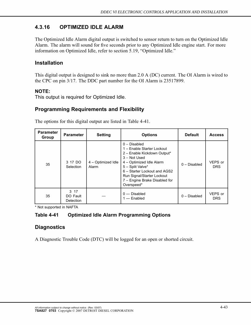
4.3.16 OPTIMIZED IDLE ALARM
The Optimized Idle Alarm digital output is switched to sensor return to turn on the Optimized IdleAlarm. The alarm will sound for five seconds prior to any Optimized Idle engine start. For moreinformation on Optimized Idle, refer to section 5.19, “Optimized Idle.”
Installation
This digital output is designed to sink no more than 2.0 A (DC) current. The OI Alarm is wired tothe CPC on pin 3/17. The DDC part number for the OI Alarm is 23517899.
NOTE:This output is required for Optimized Idle.
Programming Requirements and Flexibility
The options for this digital output are listed in Table 4-41.
ParameterGroup Parameter Setting Options Default Access
35 3 17 DOSelection
4 – Optimized IdleAlarm
0 – Disabled1 – Enable Starter Lockout2 – Enable Kickdown Output*3 – Not Used4 – Optimized Idle Alarm5 – Split Valve*6 – Starter Lockout and AGS2Run Signal/Starter Lockout7 – Engine Brake Disabled forOverspeed*
0 – Disabled VEPS orDRS
353 17
DO FaultDetection
— 0 — Disabled1 — Enabled 0 – Disabled VEPS or
DRS
* Not supported in NAFTA
Table 4-41 Optimized Idle Alarm Programming Options
Diagnostics
A Diagnostic Trouble Code (DTC) will be logged for an open or shorted circuit.
All information subject to change without notice. (Rev. 03/07) 4-437SA827 0703 Copyright © 2007 DETROIT DIESEL CORPORATION
INPUTS AND OUTPUTS
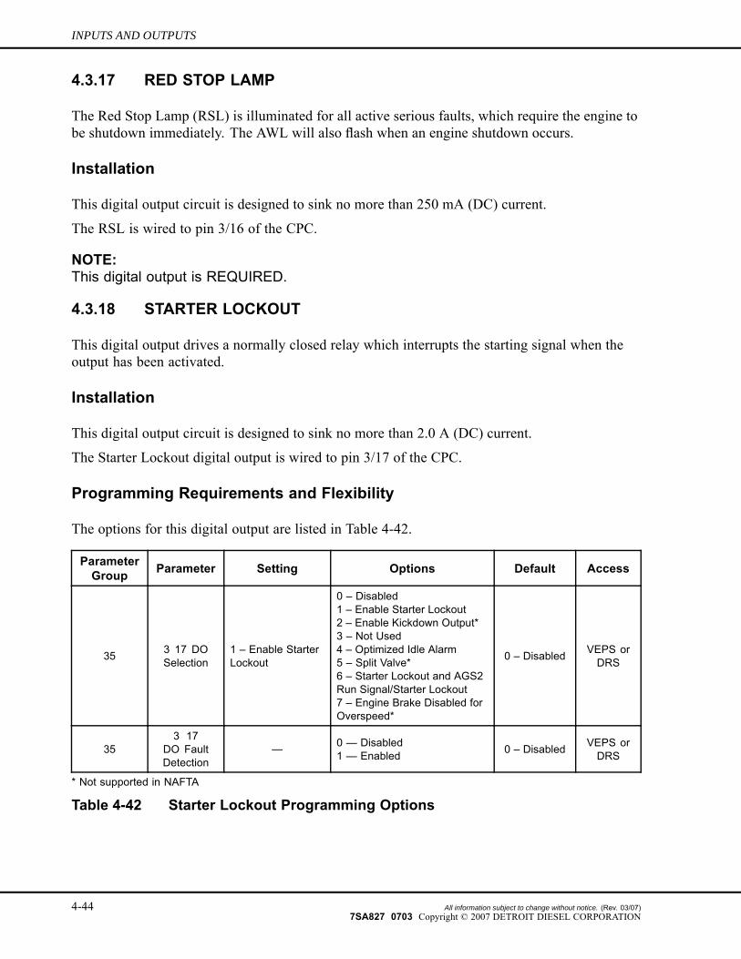
4.3.17 RED STOP LAMP
The Red Stop Lamp (RSL) is illuminated for all active serious faults, which require the engine tobe shutdown immediately. The AWL will also flash when an engine shutdown occurs.
Installation
This digital output circuit is designed to sink no more than 250 mA (DC) current.
The RSL is wired to pin 3/16 of the CPC.
NOTE:This digital output is REQUIRED.
4.3.18 STARTER LOCKOUT
This digital output drives a normally closed relay which interrupts the starting signal when theoutput has been activated.
Installation
This digital output circuit is designed to sink no more than 2.0 A (DC) current.
The Starter Lockout digital output is wired to pin 3/17 of the CPC.
Programming Requirements and Flexibility
The options for this digital output are listed in Table 4-42.
ParameterGroup Parameter Setting Options Default Access
35 3 17 DOSelection
1 – Enable StarterLockout
0 – Disabled1 – Enable Starter Lockout2 – Enable Kickdown Output*3 – Not Used4 – Optimized Idle Alarm5 – Split Valve*6 – Starter Lockout and AGS2Run Signal/Starter Lockout7 – Engine Brake Disabled forOverspeed*
0 – Disabled VEPS orDRS
353 17
DO FaultDetection
— 0 — Disabled1 — Enabled 0 – Disabled VEPS or
DRS
* Not supported in NAFTA
Table 4-42 Starter Lockout Programming Options
4-44 All information subject to change without notice. (Rev. 03/07)7SA827 0703 Copyright © 2007 DETROIT DIESEL CORPORATION
DDEC VI ELECTRONIC CONTROLS APPLICATION AND INSTALLATION
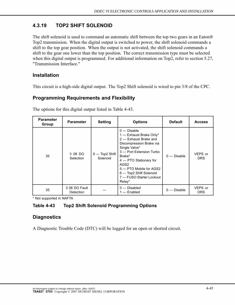
4.3.19 TOP2 SHIFT SOLENOID
The shift solenoid is used to command an automatic shift between the top two gears in an Eaton®Top2 transmission. When the digital output is switched to power, the shift solenoid commands ashift to the top gear position. When the output is not activated, the shift solenoid commands ashift to the gear one lower than the top position. The correct transmission type must be selectedwhen this digital output is programmed. For additional information on Top2, refer to section 5.27,"Transmission Interface."
Installation
This circuit is a high-side digital output. The Top2 Shift solenoid is wired to pin 3/8 of the CPC.
Programming Requirements and Flexibility
The options for this digital output listed in Table 4-43.
ParameterGroup Parameter Setting Options Default Access
35 3 08 DOSelection
6 — Top2 ShiftSolenoid
0 — Disable1 — Exhaust Brake Only*2 — Exhaust Brake andDecompression Brake viaSingle Valve*3 — Port Extension TurboBrake*4 — PTO Stationary forAGS25 — PTO Mobile for AGS26 — Top2 Shift Solenoid7 — FUSO Starter LockoutRelay*
0 — Disable VEPS orDRS
35 3 08 DO FaultDetection — 0 — Disabled
1 — Enabled 0 — Disable VEPS orDRS
* Not supported in NAFTA
Table 4-43 Top2 Shift Solenoid Programming Options
Diagnostics
A Diagnostic Trouble Code (DTC) will be logged for an open or shorted circuit.
All information subject to change without notice. (Rev. 03/07) 4-457SA827 0703 Copyright © 2007 DETROIT DIESEL CORPORATION
INPUTS AND OUTPUTS
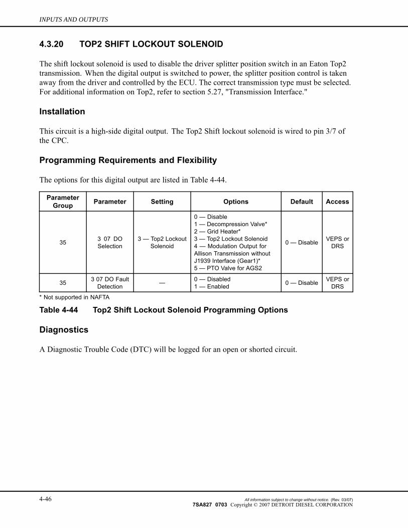
4.3.20 TOP2 SHIFT LOCKOUT SOLENOID
The shift lockout solenoid is used to disable the driver splitter position switch in an Eaton Top2transmission. When the digital output is switched to power, the splitter position control is takenaway from the driver and controlled by the ECU. The correct transmission type must be selected.For additional information on Top2, refer to section 5.27, "Transmission Interface."
Installation
This circuit is a high-side digital output. The Top2 Shift lockout solenoid is wired to pin 3/7 ofthe CPC.
Programming Requirements and Flexibility
The options for this digital output are listed in Table 4-44.
ParameterGroup Parameter Setting Options Default Access
35 3 07 DOSelection
3 — Top2 LockoutSolenoid
0 — Disable1 — Decompression Valve*2 — Grid Heater*3 — Top2 Lockout Solenoid4 — Modulation Output forAllison Transmission withoutJ1939 Interface (Gear1)*5 — PTO Valve for AGS2
0 — Disable VEPS orDRS
35 3 07 DO FaultDetection — 0 — Disabled
1 — Enabled 0 — Disable VEPS orDRS
* Not supported in NAFTA
Table 4-44 Top2 Shift Lockout Solenoid Programming Options
Diagnostics
A Diagnostic Trouble Code (DTC) will be logged for an open or shorted circuit.
4-46 All information subject to change without notice. (Rev. 03/07)7SA827 0703 Copyright © 2007 DETROIT DIESEL CORPORATION
DDEC VI ELECTRONIC CONTROLS APPLICATION AND INSTALLATION
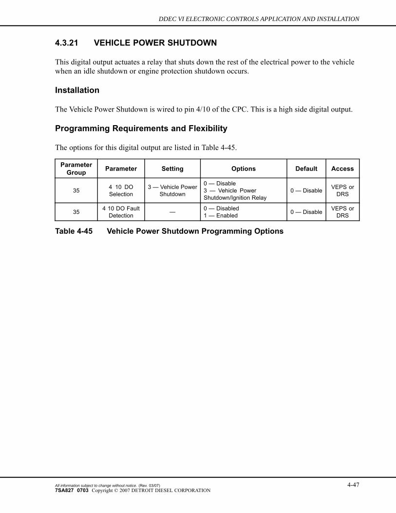
4.3.21 VEHICLE POWER SHUTDOWN
This digital output actuates a relay that shuts down the rest of the electrical power to the vehiclewhen an idle shutdown or engine protection shutdown occurs.
Installation
The Vehicle Power Shutdown is wired to pin 4/10 of the CPC. This is a high side digital output.
Programming Requirements and Flexibility
The options for this digital output are listed in Table 4-45.
ParameterGroup Parameter Setting Options Default Access
35 4 10 DOSelection
3 — Vehicle PowerShutdown
0 — Disable3 — Vehicle PowerShutdown/Ignition Relay
0 — Disable VEPS orDRS
35 4 10 DO FaultDetection — 0 — Disabled
1 — Enabled 0 — Disable VEPS orDRS
Table 4-45 Vehicle Power Shutdown Programming Options
All information subject to change without notice. (Rev. 03/07) 4-477SA827 0703 Copyright © 2007 DETROIT DIESEL CORPORATION
INPUTS AND OUTPUTS
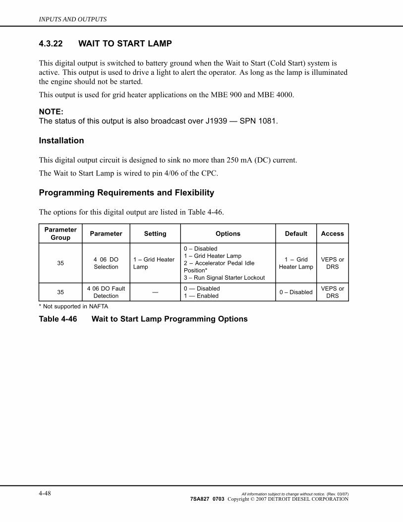
4.3.22 WAIT TO START LAMP
This digital output is switched to battery ground when the Wait to Start (Cold Start) system isactive. This output is used to drive a light to alert the operator. As long as the lamp is illuminatedthe engine should not be started.
This output is used for grid heater applications on the MBE 900 and MBE 4000.
NOTE:The status of this output is also broadcast over J1939 — SPN 1081.
Installation
This digital output circuit is designed to sink no more than 250 mA (DC) current.
The Wait to Start Lamp is wired to pin 4/06 of the CPC.
Programming Requirements and Flexibility
The options for this digital output are listed in Table 4-46.
ParameterGroup Parameter Setting Options Default Access
35 4 06 DOSelection
1 – Grid HeaterLamp
0 – Disabled1 – Grid Heater Lamp2 – Accelerator Pedal IdlePosition*3 – Run Signal Starter Lockout
1 – GridHeater Lamp
VEPS orDRS
35 4 06 DO FaultDetection — 0 — Disabled
1 — Enabled 0 – Disabled VEPS orDRS
* Not supported in NAFTA
Table 4-46 Wait to Start Lamp Programming Options
4-48 All information subject to change without notice. (Rev. 03/07)7SA827 0703 Copyright © 2007 DETROIT DIESEL CORPORATION
DDEC VI ELECTRONIC CONTROLS APPLICATION AND INSTALLATION
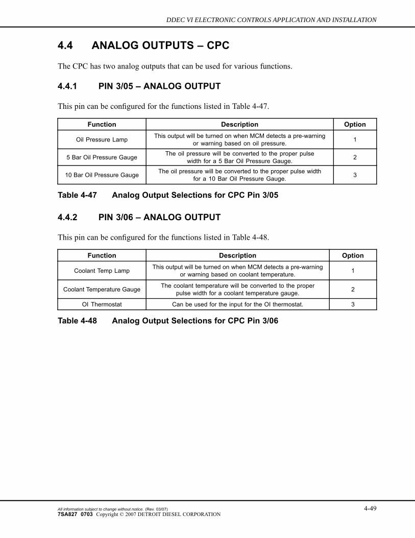
4.4 ANALOG OUTPUTS – CPC
The CPC has two analog outputs that can be used for various functions.
4.4.1 PIN 3/05 – ANALOG OUTPUT
This pin can be configured for the functions listed in Table 4-47.
Function Description Option
Oil Pressure Lamp This output will be turned on when MCM detects a pre-warningor warning based on oil pressure. 1
5 Bar Oil Pressure Gauge The oil pressure will be converted to the proper pulsewidth for a 5 Bar Oil Pressure Gauge. 2
10 Bar Oil Pressure Gauge The oil pressure will be converted to the proper pulse widthfor a 10 Bar Oil Pressure Gauge. 3
Table 4-47 Analog Output Selections for CPC Pin 3/05
4.4.2 PIN 3/06 – ANALOG OUTPUT
This pin can be configured for the functions listed in Table 4-48.
Function Description Option
Coolant Temp Lamp This output will be turned on when MCM detects a pre-warningor warning based on coolant temperature. 1
Coolant Temperature Gauge The coolant temperature will be converted to the properpulse width for a coolant temperature gauge. 2
OI Thermostat Can be used for the input for the OI thermostat. 3
Table 4-48 Analog Output Selections for CPC Pin 3/06
All information subject to change without notice. (Rev. 03/07) 4-497SA827 0703 Copyright © 2007 DETROIT DIESEL CORPORATION
INPUTS AND OUTPUTS
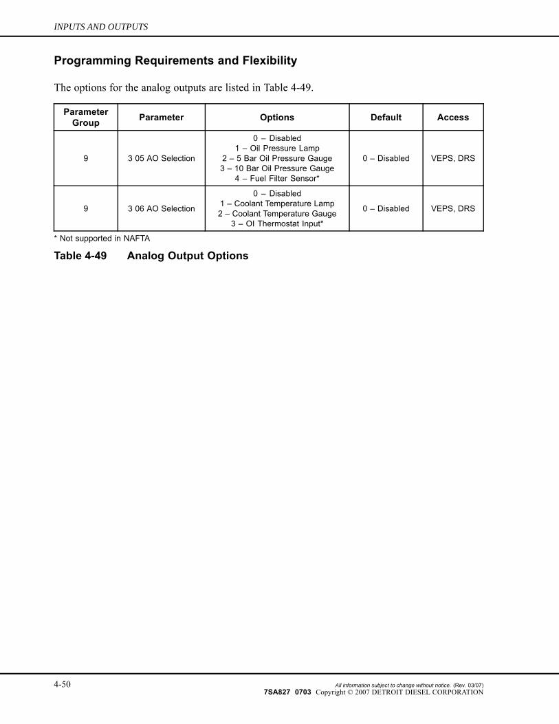
Programming Requirements and Flexibility
The options for the analog outputs are listed in Table 4-49.
ParameterGroup Parameter Options Default Access
9 3 05 AO Selection
0 – Disabled1 – Oil Pressure Lamp
2 – 5 Bar Oil Pressure Gauge3 – 10 Bar Oil Pressure Gauge
4 – Fuel Filter Sensor*
0 – Disabled VEPS, DRS
9 3 06 AO Selection
0 – Disabled1 – Coolant Temperature Lamp2 – Coolant Temperature Gauge
3 – OI Thermostat Input*
0 – Disabled VEPS, DRS
* Not supported in NAFTA
Table 4-49 Analog Output Options
4-50 All information subject to change without notice. (Rev. 03/07)7SA827 0703 Copyright © 2007 DETROIT DIESEL CORPORATION
DDEC VI ELECTRONIC CONTROLS APPLICATION AND INSTALLATION
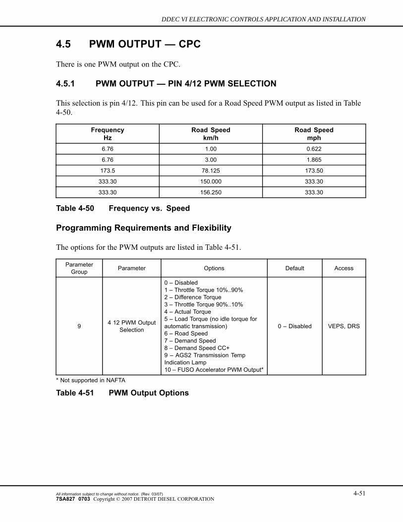
4.5 PWM OUTPUT — CPC
There is one PWM output on the CPC.
4.5.1 PWM OUTPUT — PIN 4/12 PWM SELECTION
This selection is pin 4/12. This pin can be used for a Road Speed PWM output as listed in Table4-50.
FrequencyHz
Road Speedkm/h
Road Speedmph
6.76 1.00 0.622
6.76 3.00 1.865
173.5 78.125 173.50
333.30 150.000 333.30
333.30 156.250 333.30
Table 4-50 Frequency vs. Speed
Programming Requirements and Flexibility
The options for the PWM outputs are listed in Table 4-51.
ParameterGroup Parameter Options Default Access
9 4 12 PWM OutputSelection
0 – Disabled1 – Throttle Torque 10%..90%2 – Difference Torque3 – Throttle Torque 90%..10%4 – Actual Torque5 – Load Torque (no idle torque forautomatic transmission)6 – Road Speed7 – Demand Speed8 – Demand Speed CC+9 – AGS2 Transmission TempIndication Lamp10 – FUSO Accelerator PWM Output*
0 – Disabled VEPS, DRS
* Not supported in NAFTA
Table 4-51 PWM Output Options
All information subject to change without notice. (Rev. 03/07) 4-517SA827 0703 Copyright © 2007 DETROIT DIESEL CORPORATION

INPUTS AND OUTPUTS
THIS PAGE INTENTIONALLY LEFT BLANK
4-52 All information subject to change without notice. (Rev. 03/07)7SA827 0703 Copyright © 2007 DETROIT DIESEL CORPORATION