Embed Size (px)
Citation preview

1
EQ015R2
4 POINT MANUALLEVELING SYSTEM Installation/Operation/Warranty Guide
Effective March 2021
2
(800) 846-9659EQSystems.us
4 Point Manual Leveling SystemInstallation, Troubleshooting & Warranty Guide AM, AJ, SM, HM, SL, DP Hydraulic Leg Assemblies
Effective January 2021Revised March 2017
Contents
Required Tools & Parts Page 3
Installation Page 4 & 5
Manifold & Connections Page 5
Hydraulic Fluid & Purging Page 6 - 8
Operation Page 8 & 9
Manual Override Pages 9 - 12
Troubleshooting Pages 13 & 14
Warranty Pages 15 & 16
Diagrams Appendix
EQ015R2
3
Eq Systems 4 Point Leveling SystemInstallation Guide
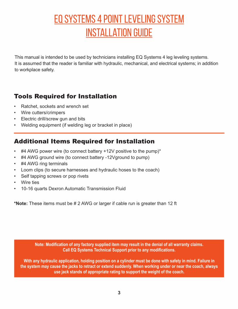
Tools Required for Installation
Additional Items Required for Installation
• Ratchet, sockets and wrench set • Wire cutters/crimpers • Electric drill/screw gun and bits• Welding equipment (if welding leg or bracket in place)
• #4 AWG power wire (to connect battery +12V positive to the pump)*• #4 AWG ground wire (to connect battery -12Vground to pump)• #4 AWG ring terminals• Loom clips (to secure harnesses and hydraulic hoses to the coach)• Self tapping screws or pop rivets • Wire ties• 10-16 quarts Dexron Automatic Transmission Fluid
*Note: These items must be # 2 AWG or larger if cable run is greater than 12 ft
Note: Modification of any factory supplied item may result in the denial of all warranty claims.Call EQ Systems Technical Support prior to any modifications.
With any hydraulic application, holding position on a cylinder must be done with safety in mind. Failure in the system may cause the jacks to retract or extend suddenly. When working under or near the coach, always
use jack stands of appropriate rating to support the weight of the coach.
This manual is intended to be used by technicians installing EQ Systems 4 leg leveling systems.It is assumed that the reader is familiar with hydraulic, mechanical, and electrical systems; in additionto workplace safety.
4
Installation
Reference Chart for Installing Jack Legs
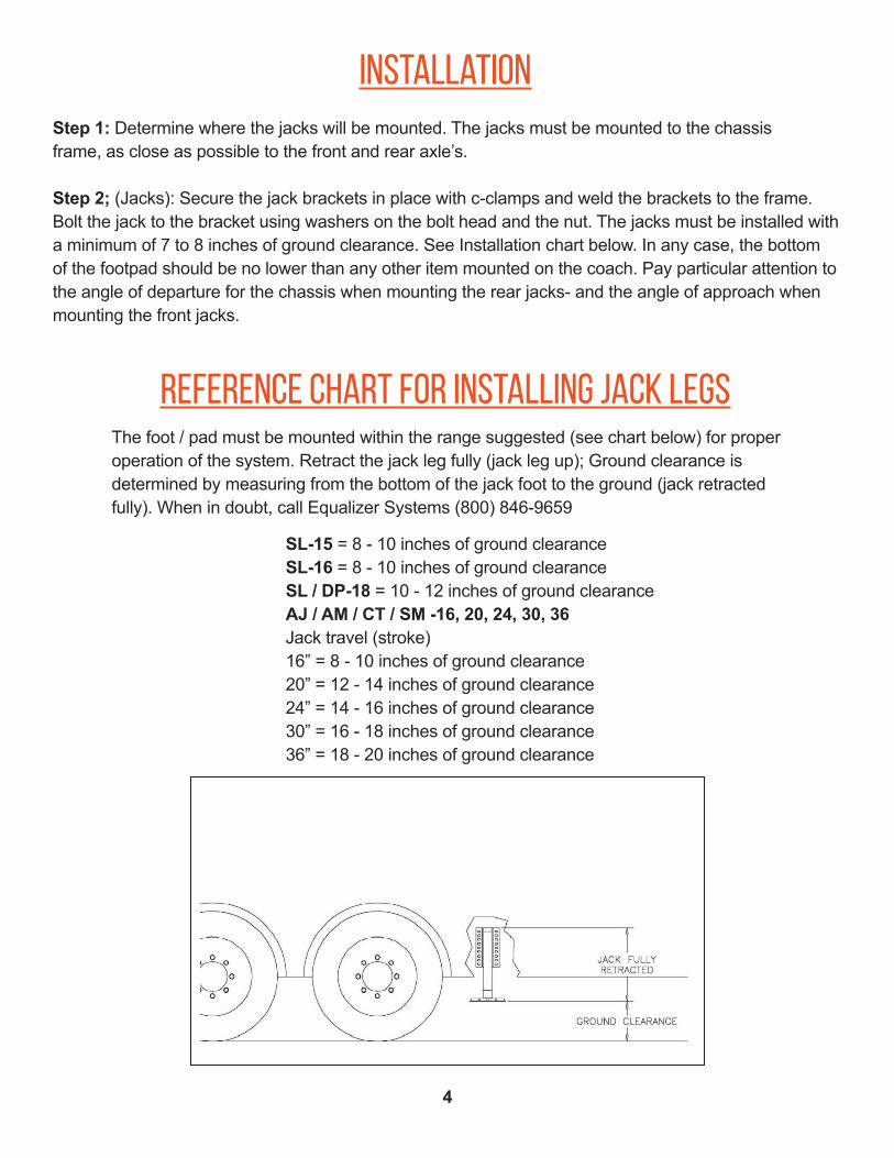
Step 1: Determine where the jacks will be mounted. The jacks must be mounted to the chassisframe, as close as possible to the front and rear axle’s.
Step 2; (Jacks): Secure the jack brackets in place with c-clamps and weld the brackets to the frame. Bolt the jack to the bracket using washers on the bolt head and the nut. The jacks must be installed with a minimum of 7 to 8 inches of ground clearance. See Installation chart below. In any case, the bottom of the footpad should be no lower than any other item mounted on the coach. Pay particular attention to the angle of departure for the chassis when mounting the rear jacks- and the angle of approach when mounting the front jacks.
The foot / pad must be mounted within the range suggested (see chart below) for proper operation of the system. Retract the jack leg fully (jack leg up); Ground clearance is determined by measuring from the bottom of the jack foot to the ground (jack retracted fully). When in doubt, call Equalizer Systems (800) 846-9659
SL-15 = 8 - 10 inches of ground clearanceSL-16 = 8 - 10 inches of ground clearanceSL / DP-18 = 10 - 12 inches of ground clearanceAJ / AM / CT / SM -16, 20, 24, 30, 36Jack travel (stroke)16” = 8 - 10 inches of ground clearance20” = 12 - 14 inches of ground clearance24” = 14 - 16 inches of ground clearance30” = 16 - 18 inches of ground clearance36” = 18 - 20 inches of ground clearance
5
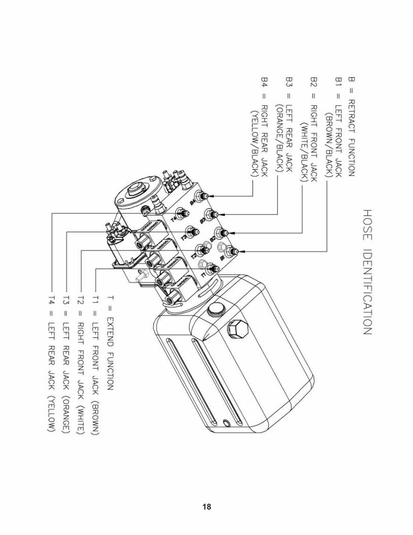
Installation of hoses to the manifold
Step 3 (Pump): Install the pump kit on the coach. The pump must be mounted in a location that is reasonable to route all of the hydraulic hoses to the manifold. It must be accessible for filling the reservoir and monitoring the fill level. Take note if the unit is equipped with the manual override option. The pump handle, cartridge valves and directional valves must be accessible to manually override the system. If the pump is equipped with the manual override screw on the end of the motor, than be sure to allow access to that side of the pump. In most applications, a side storage compartment will provide the ideal location. An additional mounting box or tray may be used on other style vehicles.
Step 4 (Fittings): Install the hydraulic adaptor fittings in the top and bottom of each jack and install the fittings into the manifold. The straight thread o-ring side always goes to the cylinder or manifold. The tapered side will get the hose attached to it. When installing straight fittings into the leg or manifold, tighten to 15 lbs-ft. When using 90 degree fittings, turn until finger tight, position correctly, then tighten the jam nut to 15 lbs-ft.
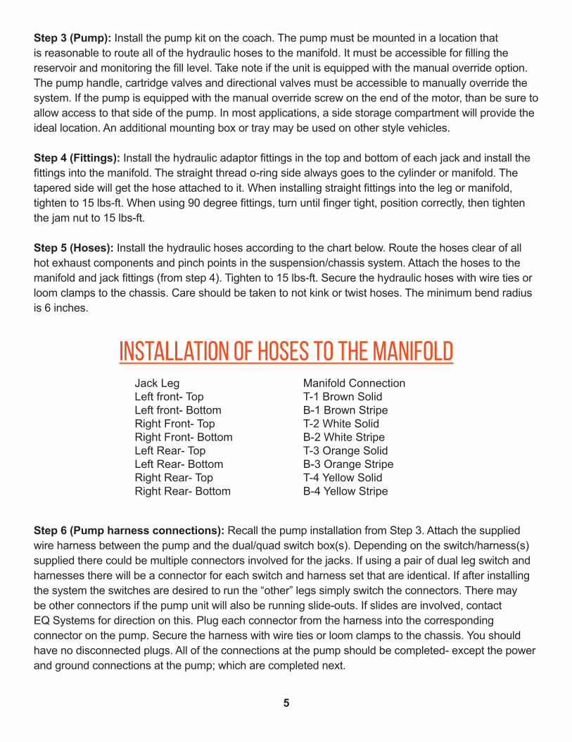
Step 5 (Hoses): Install the hydraulic hoses according to the chart below. Route the hoses clear of all hot exhaust components and pinch points in the suspension/chassis system. Attach the hoses to the manifold and jack fittings (from step 4). Tighten to 15 lbs-ft. Secure the hydraulic hoses with wire ties or loom clamps to the chassis. Care should be taken to not kink or twist hoses. The minimum bend radius is 6 inches.
Step 6 (Pump harness connections): Recall the pump installation from Step 3. Attach the supplied wire harness between the pump and the dual/quad switch box(s). Depending on the switch/harness(s) supplied there could be multiple connectors involved for the jacks. If using a pair of dual leg switch and harnesses there will be a connector for each switch and harness set that are identical. If after installing the system the switches are desired to run the “other” legs simply switch the connectors. There maybe other connectors if the pump unit will also be running slide-outs. If slides are involved, contactEQ Systems for direction on this. Plug each connector from the harness into the corresponding connector on the pump. Secure the harness with wire ties or loom clamps to the chassis. You should have no disconnected plugs. All of the connections at the pump should be completed- except the power and ground connections at the pump; which are completed next.
Jack Leg Manifold Connection Left front- Top T-1 Brown Solid Left front- Bottom B-1 Brown Stripe Right Front- Top T-2 White Solid Right Front- Bottom B-2 White Stripe Left Rear- Top T-3 Orange Solid Left Rear- Bottom B-3 Orange Stripe Right Rear- Top T-4 Yellow Solid Right Rear- Bottom B-4 Yellow Stripe
6
power connections foruni-directional motor pump - 1551
Purge Instructions for Uni-Directional Pump- 1551
Step 7 (Pump +12V): Attach a # 4 gauge wire (# 2 gauge if the run is over 12ft.) between the positive +12v terminal on the battery and the terminal (this terminal will have a yellow or red fused wire attached to it) at the motor solenoid on the pump. This supply may be fused at the source with a 150-amp circuit breaker. This +12v supply must be a dedicated and isolated circuit (not shared with other devices).
Step 8 (Pump -12V): Attach a # 4 gauge wire (# 2 gauge if the run is over 12ft.) between the negative -12v terminal on the battery and the ground stud on the pump. This is the preferred method of grounding. If grounding the pump to the chassis, both the cable from the pump to the frame and the battery negative to the frame must meet the requirement above. The connections must be sound, free of paint and not susceptible to corrosion. It is not acceptable to allow the pump mounting bolts to be the sole grounding connection.
These units can be identified by a single motor solenoidor the # 1551 on the pump data label
Step 9 Retraction Purge: The retraction side of the cylinders is the first to be purged of air. Fill the reservoir fully with Dexron Transmission fluid. This is the same fluid used in GM vehicles. Begin to purge the retraction side of the system by pushing the switch (If equipped with a keyed switch, the key must be in the on position) to Trailer Down for each jack(s).The jacks may be run in pairs (front pair & rear pair). You will know when the retraction side of the hydraulic circuit is pressurized when the fluid level in the reservoir stops and the pump changes sound (bypass mode). Release the switch(s) when this occurs. Refill the reservoir to full.
Full Purge: Next, cycle the system by lowering each jack to the ground, by pressing the switch to the Trailer UP position. Do not allow the jack to lift the coach. After all jacks are in contact with the ground, press the switch(s) to retract all of the jacks. Refill the reservoir to full. Next run the jacks in pairs (front pair & rear pair) to full extension by holding the switches (front pair or rear pair) in the Trailer Up position simultaneously. Monitor the fluid level and check all fittings for leakage. Retract the jacks by pressing the rocker switches to the Trailer down position (this should be done in pairs). Recheck the reservoir and fill to full. Note the fluid level in the reservoir is at maximum when all jacks are fully retracted and minimum when jacks are fully extended. This full extension and retraction in pairs should be repeated 3-4 times.• Allowing the air to dissipate through the reservoir and maintaining the reservoir fluid level will get things working faster.
7
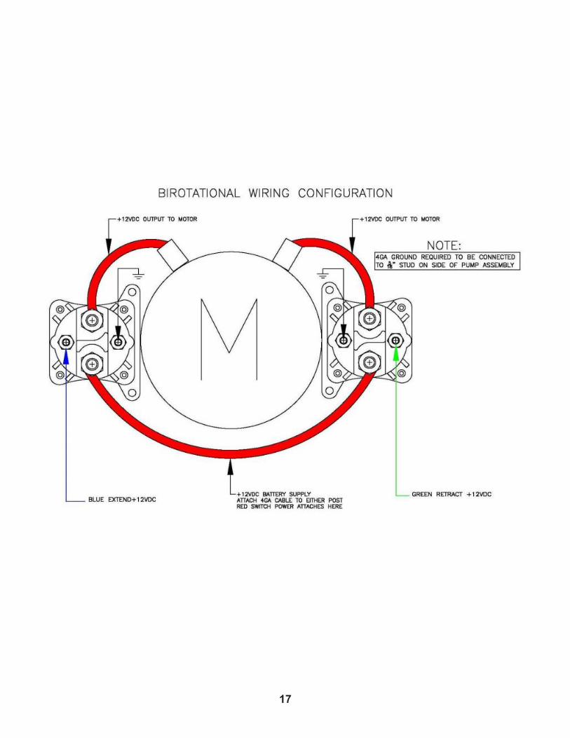
Power Connections for Bi Rotational Pump
Purging of Bi Rotational pumps- 2390, 2532, 2542, 3043
Step 7 (Pump +12v):
Pump # 2390, 2532, 2542: Attach a # 4 gauge wire (# 2 gauge if the run is over 12ft.) between the positive +12v terminal on the battery and the terminal on the motor solenoid. This terminal will have a cable that joins both of the motor solenoids. This terminal also will have a red or yellow fused wire attached to it. This supply may be fused at the source with a 120-amp circuit breaker. This +12v supply must be a dedicated and isolated circuit (not shared with other devices).
Pump # 3043: This unit will have a single reversing contactor. The positive battery connection is made to the + terminal on this contactor. There will also be a fused wire- red or yellow at this terminal. Use # 6 or # 4 gauge wire for this supply.
Step 8 (Pump -12V): Attach a # 4 gauge wire (# 2 gauge if the run is over 12ft.) between the negative -12v terminal on the battery and the ground stud on the pump. This is the preferred method of grounding. If grounding the pump to the chassis, both the cable from the pump to the frame and the battery negative to the frame must meet the requirement above. The connections must be sound, free of paint and not susceptible to corrosion. It is not acceptable to allow the pump mounting bolts to be the sole grounding connection.
Step 9: This procedure must be performed both with the initial installation & running of hydraulic systemand following installation of the pump assembly and jack(s). This step applies only to systems that are equipped with the Bi-Rotational pump. All electrical and hose connections must be completed before thepurging process. You must follow this procedure strictly. Any deviation from the process will cause the purging process to become difficult and time consuming.
Fill the reservoir with ATF Dexron.
1. Remove the fitting that is installed into port G-1, or attach a hose to the coupler. Place into a clean container. This will allow retract side air to escape to atmosphere.
2. Run the pump to extend the jacks(s) (This is done by pressing the rocker switch(s) to the Trailer Up position). Maintain the fluid level in the reservoir between 1/4 and 1/2 full. Do not allow thereservoir to run empty. If jacks(s) will not fully extend, crack loose the upper hose(s) at the jack(s) and run the pump to extend until air is expelled. Use Caution - hydraulic fluid will be under high pressure. Retighten the hoses and complete the extension of the jack(s). Maintain the fluid level as described above.
8
Equalizer Systems Operation
• The reservoir fluid level will be greatest when all jacks are fully retracted; the fluid level will be lowest when all jacks are fully extended
• Maintain the fluid level at least ¾ full when the jacks are retracted.
• It does no good to run the pump and try to move the jacks when the reservoir is full of foam. Pumping foam will only reintroduce air into the system and will prolong the
• process unnecessarily.
• Allowing the air to dissipate through the reservoir and maintaining the reservoir fluid level will get things working faster.
3. Reinstall the fitting or plug into G-1 or remove the hose attached to the coupler. (See # 1 above)
4. Run the pump to retract the jack(s) (this is done by pressing the rocker switch(s) in the trailer down position) Check instructions for operation for more on this. Maintain the fluid level as above.Do not fill the reservoir to full until after the legs are fully retracted.
5. IMPORTANT - If fluid in reservoir appears to be aerated (foaming), allow unit to rest until foam dissipates (approx 5-10 minutes).
6. Fully extend and retract jack(s) a minimum of 3 times. Allow any foam in the reservoir to dissipate as needed. Maintain the fluid level in the reservoir as needed.
*It is always the responsibility of the vehicle operator to visuallyconfirm that the jacks are fully retracted and safe for travel*
Keyed Switch:A keyed switch is located at the switchgear assembly(s). The key needs to be turned to the “on” position for operation. This keyed switch is a security feature intended to help minimize the possibility of unauthorized system operation. The keyed switch should only be turned to the on position when it is desired to operate the jacks. At all other times, the keyed switch must be turned to the “off” position and the key removed. This includes when the trailer/vehicle is parked with the jacks in any position(extended or retracted). During transport of the vehicle, the keyed switch must be turned to the off position and the key removed.
Additional Notes Regarding Purging
9
Manual Override Procedure for 4 Jack System
Pump #s 2390, 2532, 2542, 2015, 2017
Basic Operation:There is a rocker switch for each jackleg. Your system will either have two switchgear assemblies, both with two rocker switches, or you will have one switchgear assembly with 4 rocker switches.
Identify the rocker switch for the jack(s) that you want to run and operate the rocker switch. Push‘Trailer Up’ to extend the jack and lift the trailer, or operate the switch in the ‘Trailer Down’ position toretract the jack(s) and lower the trailer.
The jacks may be operated individually, in pairs, or in any multiples- as long as they are operated in the same direction (extend or retract).
The Recommended Process of Extending the Jacks to Lift and Level the Trailer:Extend the front jacks as a pair by pressing the rocker switches for the front jacks in the “Trailer Up”position. When the front jacks are planted, move to the rear jacks. Run them as a pair- “Trailer Down”until they are planted. Then operate the jacks individually or in pairs to level the vehicle. Care should be taken to insure that over extending any individual jack(s) does not cause stress or twisting of the vehicle.
To Lower the Trailer, (Retract the jacks):Prior to lowering the vehicle (retracting the jacks) check around and under the unit.This is basically the reverse order of extending the jacks. Use the rocker switches in pairs by pressing the rocker switch(s) in the “Trailer Down” position. Care should be taken to avoid twisting the trailer as it is being lowered. Fully retract the jacks prior to moving the vehicle.
Most systems manufactured after January 2012 have some type of override system that will allow the operation of the jacks if there is a failure of the power supply, control circuit, or motor failure. It is in place to restore the vehicle to transportable so that the issue can be dealt with at a later time and place. It is not designed to be used for general operation. It is recommended that if the failure is simply a dead battery, that the batteries be charged so that the system can be operated normally rather than going through the following procedure(s).
• Your hydraulic motor may be equipped with a manual override output shaft. Youmust use a drill with a 7/16” socket driver.
•The drill must be capable of producing a minimum of 2000 r.p.m. f or the pump to develop appropriate pressure output.
10
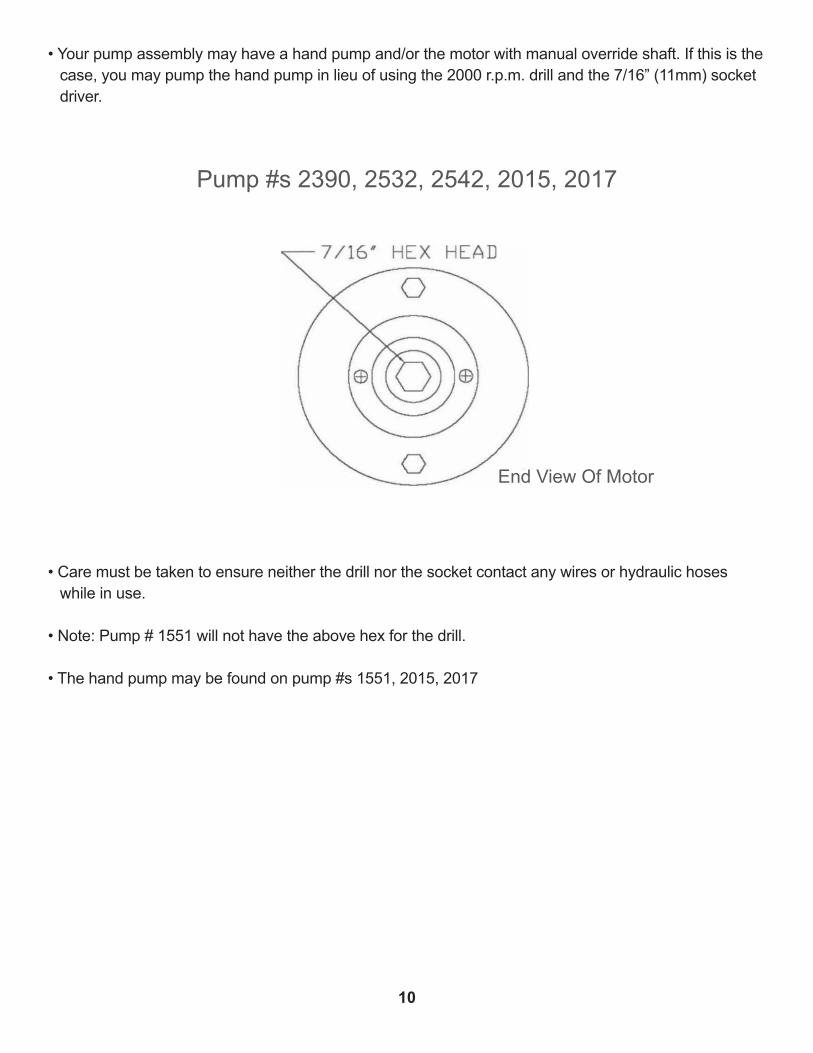
• Your pump assembly may have a hand pump and/or the motor with manual override shaft. If this is the case, you may pump the hand pump in lieu of using the 2000 r.p.m. drill and the 7/16” (11mm) socket driver.
• Care must be taken to ensure neither the drill nor the socket contact any wires or hydraulic hoses while in use.
• Note: Pump # 1551 will not have the above hex for the drill. • The hand pump may be found on pump #s 1551, 2015, 2017
Pump #s 2390, 2532, 2542, 2015, 2017
End View Of Motor
11
Retracting your jack(s) using the manual override (if Equipped)
Uni-Directional PumpsPump #s 2015, 2017, 1551
The individual cartridge valves are clustered together on the side of the pump manifold. They are labeled 1 thru 4. Locate the screws on the appropriate cartridge valve(s). Using a small flat blade screwdriver or 1/8” Allen wrench, turn the screw(s) clockwise until seated in. Locate Valve DV-2. This will have either an Allen override screw or a red knurled knob. This valve will be on the opposite side of the manifold from the cluster of cartridge valves. If equipped with the Allen screw type, turn the Allen screw in until seated. If equipped with the red knurled knob, pull the red knob out and turn 1/4 turn clockwise. The knob will remain in the ‘out’ position.
To retract: locate DV-1. This valve will be on the side of the manifold adjacent to the cluster of cartridge valves. Pull the red knob out and turn 1/4 turn clockwise. The knob will remain in the ‘out’ position.
If equipped with override hex on motor:Remove the black plastic cap from the end of the motor (Can use a small flat head screwdriver).Place the drill with the 7/16in socket on the manual override shaft located at the end of the motor. Run drill in a clockwise direction at 2000 r.p.m.(minimum). The jack(s) will retract.
If equipped with Hand Pump:Insert handle into hand pump and operate back and forth until jacks are fully retracted. This will takemultiple operations to fully retract the jacks. It may take 50 strokes prior to getting the jacks to move.
Following manual override operation, failure to return all valves to normal position may cause one or more jack legs to drift down from their retracted (stowed) position. For cartridge valves, rotate the center screw fully counter-clockwise. For directional valves, rotate the red knob until it ‘snaps’ back to thenormal position - or return the Allen screw to the original “out” counter-clockwise position.
*Note: The normal operating position of the screw in the cartridge valve(s) is the counter-clockwise ‘out’ position. The only time the valve should be shifted manually is when attempting to operate jack(s) via manual override.
**Note: The normal operating position of the red knob on the directional valve(s) is the ‘in’ position. The only time the valve should be shifted manually is when attempting to operate jack(s) via manual override.
To Extend The Jack(s):To extend the jack(s), follow all of the above steps EXCEPT DO NOT manually shift directional valve DV1 as described in step # 3 above.
12
To operate your jack(s) using the manual override (with bi-rotational motor)
Manual Override for Bi-Rotational Style Pumps
Pump #s 2390, 2532, 2542, 3043
• Your hydraulic pump may be equipped with a Bi-Rotational motor. You will use a 2000 r.p.m. drill and a 7/16” socket or 1/4” Allen drive
• Care must be taken to ensure neither the drill nor the socket contact any wires or hydraulic hoses while in use.
Locate the individual cartridge valves that are clustered together on the side of the pump manifold. They are labeled 1 thru 4. Locate the screws on the appropriate cartridge valve(s). Using a small flat blade screwdriver or 1/8” Allen wrench (depending on valve type), turn the screw(s) clockwise until seated in. The pump may or may not have a DV-2 valve on the opposite side of the manifold. If it does have this valve, turn the screw clockwise until seated in as above.
Remove the black plastic cap from the end of the motor. Use a small flat head screwdriver. Place the drill with the 7/16” socket on the manual override shaft located at the end of the motor. The 3043 pump will have a foil sticker override which will need a ¼ Allen drive with the drill..
To retract your jack(s) run the drill in the counter-clockwise direction.
To extend your jack(s), run the drill in the clockwise direction.
When manual override is complete, return the cartridge valve(s) to the normal position(s). Reinstall black plastic cap on motor.
Following manual override operation, failure to return all valves to normal position may cause one or more jack legs to drift down from their retracted (stowed) position. For cartridge valves, rotate the center screw fully counter-clockwise. For directional valves, rotate the red knob until it ‘snaps’ back to the normal position - or return the Allen screw to the original “out” counterclockwise position.
*Note* The normal operating position of the screw in the cartridge valve is the counterclockwise ‘out’ position. The only time the valve should be shifted manually is when attempting to operate jack(s) via manual override.
13
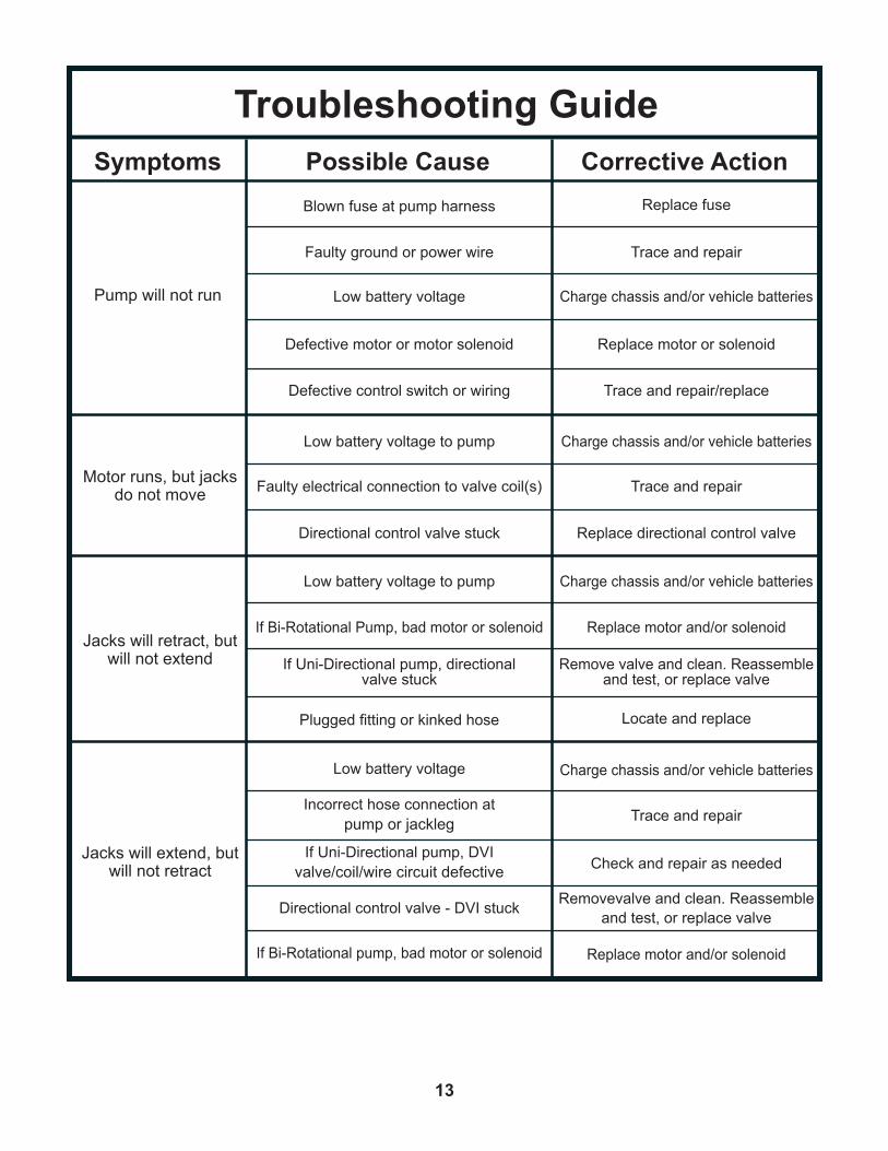
Troubleshooting GuideSymptoms
Pump will not run
Blown fuse at pump harness Replace fuse
Faulty ground or power wire Trace and repair
Low battery voltage Charge chassis and/or vehicle batteries
Defective motor or motor solenoid Replace motor or solenoid
Defective control switch or wiring Trace and repair/replace
Low battery voltage to pump Charge chassis and/or vehicle batteries
Faulty electrical connection to valve coil(s) Trace and repair
Directional control valve stuck Replace directional control valve
Low battery voltage to pump Charge chassis and/or vehicle batteries
If Bi-Rotational Pump, bad motor or solenoid Replace motor and/or solenoid
If Uni-Directional pump, directionalvalve stuck
Remove valve and clean. Reassembleand test, or replace valve
Plugged fitting or kinked hose Locate and replace
Low battery voltage Charge chassis and/or vehicle batteries
Incorrect hose connection atpump or jackleg Trace and repair
If Uni-Directional pump, DVIvalve/coil/wire circuit defective Check and repair as needed
Directional control valve - DVI stuck Removevalve and clean. Reassembleand test, or replace valve
If Bi-Rotational pump, bad motor or solenoid Replace motor and/or solenoid
Motor runs, but jacks do not move
Jacks will retract, but will not extend
Jacks will extend, but will not retract
Possible Cause Corrective Action

14
Symptoms
Jack(s) will notsupport
vehicle weight
External fluid loss Tighten fittings or replace component
Internal fluid bypass (cylinder) Replace cylinder
Manifold valve not holding fluid pressure Replace valve
Manifold valve override screwin improper position Return screw to proper (out) position
Air in hydraulic system Extend and retract jacks fully to purge
External fluid leak Tighten fittings or replace component
Valve- DV2 override screw in improper position Return screw to proper (out) position
Valve- DV2 defective Replace Valve
Defective hydraulic cylinder Replace hydraulic cylinder
Air in hydraulic systemExtend and retract jacks fully
to purge
Extend and retract jacks fullyto purge
Extend and retract jacks fullyto purge
Low fluid level Add fluid (dexron ATF) as needed
Air in hydraulic system
Air in hydraulic system
Improper restrictor fitting at top of jack Install proper fitting
Jacks will not stayin the retracted
position
Jacks operate‘jerky’ or ‘mushy’
Jacks pulsate or are‘jerky’ in retraction
(under load)
Possible Cause Corrective Action
If your problem is not listed, call EQ Systems at (800) 846-9659Prior Authorization for warranty is required

15
1. Only warranty claims with prior written or verbal authorization from EQ Systems will be recognized, all other claims will be denied.
2. EQ Systems warrants slide out and leveling system components for a period of one year from the date of original sale of the vehicle. This warranty covers defects in material and workmanship only. EQ Systems is not liable for any damage due to abuse, neglect, misuse, negligence, misapplication, error of operation, accidental or purposeful damage or damage due to an “act of God” such as, wind or rain damage, flood, lightning or other natural occurrence of the like. EQ Systems limited warranty is applicable to the EQ Systems components only and does not apply to the vehicle, apparatus or property to which it is attached. Warranty parts will be shipped at no charge if the repair is authorized by an EQ Systems representative. Purchased components used in authorized warranty repairs will be reimbursed at the original purchase price.
3. Labor and freight expenses due to warrantable parts defects or workmanship will be reimbursed for a period of one year from the date of original sale of the vehicle. Freight expenses will either be prepaid by EQ Systems or reimbursed at the UPS Ground rate only. Any additional shipping charges or requirements are the obligation of the vehicle owner or service center performing the warranty repair. The owner or service center’s obligation may include overseas shipping charges, border fees, brokerage fees and any other additional fee of the like.
4. Warranty labor will be reimbursed only for claims that have prior written or verbal authorization from an EQ Systems representative. Warranty labor compensation is required to correspond with the “Warranty Parts Replacement Time Guideline” published by EQ Systems. Any warranty repair not listed on this guideline will require prior authorization from an EQ Systems representative. A reasonable time allowance will be determined by the EQ Systems representative. Any warranty repair that is not listed on this guideline that is performed without prior authorization will be denied without exception. Time associated with learning about the repair or excessive diagnostic and installation time will not be reimbursed. Warranty labor will be reimbursed at the authorized service center’s published shop rate if the rate is reasonable for that region. Overtime labor will not be reimbursed without exception.
5. Labor, parts and freight credit (if applicable) will be sent after the parts are tested and the warranty claim is validated. Returned parts that are found to be in normal operating condition are not warrantable and will be charged to the owner or service center. EQ Systems reserves the right to charge back the service center for labor claim payments previously submitted if the installation of the warranted part is found to be inadequate at a later date.
6. Claims will be denied if the date submitted is greater than 30 days from the repair date.
7. Prior authorization is required before parts may be sent back to EQ Systems. A Return Authorization Number is required for items to be accepted.
EQ Systems Limited Warranty PolicyMarch 2017
16
8. Complete systems are not warranted unless authorized by an EQ Systems representative. There are absolutely no exceptions to this clause.
9. Warranty coverage for parts or systems sold by non-authorized resellers (such as live or internet auctions) will be at the discretion of EQ Systems.
10. EQ Systems is not liable for loss of time, manufacturing costs, labor, material, loss of profits, direct or indirect damages incurred by the vehicle manufacturer.
11. Excessive warranty labor resulting from inadequate access to the EQ Systems product will not be reimbursed.
12. EQ Systems will not pay a markup on warranty parts unless required by law.
13. Travel expenses, hotel, telephone, fuel or any other expenses of the like are not covered under warranty.
Replacement Parts:1. Replacement parts are warranted under the same guidelines listed above for the remainder of the original warranty or 90 days, whichever is longer. Proof of warranty repair date and original vehicle purchase date are required.
No additional warranties, expressed or implied, are authorized by EQ SystemsThis warranty voids all previous issues.Questions concerning this warranty should be directed to:
EQ Systems55169 CR 3 NorthElkhart, IN 46515
(800) 846-9659(574) 266-6083 fax
To activate your warranty,please visit our website at EQSystems.us/activate-warranty
EQ015R2
17
18
19