Embed Size (px)
Citation preview

European Commission
Research Programme of the Research Fund for Coal and Steel
STEEL-EARTH
STEEL-BASED APPLICATIONS IN EARTHQUAKE-PRONE AREAS
PRECASTEEL
PREFABRICATED STEEL STRUCTURES FOR LOW-RISE
BUILDINGS IN SEISMIC AREAS
TECHNICAL SHEET
FERRIERE NORD SpA CONTRIBUTION
Authors: dr. Loris Bianco
ing. Roberta Mallardo
ing. Pietro Filipuzzi

STEEL-EARTH project - WP1 - Technical sheet
1
TABLE OF CONTENTS
1. Introduction ........................................................................................................................................ 2
2. Design objectives ............................................................................................................................... 2
3. Design inputs ...................................................................................................................................... 3
4. Specific design concept ...................................................................................................................... 5
5. Design methodology .......................................................................................................................... 6
6. Details ................................................................................................................................................ 8
7. Comparison between r.c. wall and steel bracing systems ................................................................ 10
ANNEX 1 .............................................................................................................................................. 14
ANNEX 2 .............................................................................................................................................. 23
ANNEX 3 .............................................................................................................................................. 32

STEEL-EARTH project - WP1 - Technical sheet
2
1. Introduction
The following paragraphs explains the main scope of Ferriere Nord SpA (FeNO) contribution on
Precasteel research, about the analysis of precast double-slab r.c. wall as alternative bracing system in
low-rise steel commercial buildings situated in seismic areas, in particular the definition of shear wall
configurations and load levels with reference to an innovative simplified pre-design procedure.
One of the parts of the project research that has deeply developed by FeNO was focused on the
comparison between reinforced concrete walls solutions towards concentric and eccentric steel bracing
systems, underlining their capacity of dissipating seismic energy and consequently the influence in
terms of cost of construction.
2. Design objectives
The mentioned simplified design approach has the aim to accelerate and make easier all the decisions
that has to be taken about feasibility of a project and, the last but not the least, provide an economic
estimation of the investment.
On the basis of a preliminary statistical data analysis, structural configurations were defined fixing
geometries (bays length, storey number, floor configuration or roof slope) in order to be consistent
with housed activities, industrial or commercial, and to be competitive with concrete market shares.
The selected structural solutions for commercial building activities were iteratively designed varying
geometrical parameters and resisting static schemes in order to define the optimum steel and steel-
concrete composite solutions.
The iterative design of many structures, integrated with the cost analysis, was transformed in a
complete performance analysis where structural performance (assessed applying Eurocode design
framework) were harmonized with construction costs. The cost model considered information coming
from three different countries (Italy - Southern Europe; Germany - Central Europe; Romania - Eastern
Europe), in such a way to adopt standardized reference values and to individuate in which national
markets some solutions can be competitive or not.
Concerning commercial buildings, the solutions derived from the statistical analysis and from the cost
analysis were in general a modular solution in which two main structures were coupled and devoted to
different roles:
- a gravity structure to sustain vertical loads;
- a bracing structure to sustain seismic loads.
The refined numerical simulations and the studies for optimizing the structural performance of
commercial building solutions where devoted to the assessment of real seismic performance of
different horizontal bracing systems. The following structural configurations were analysed:
- commercial buildings equipped with concentrically braced steel frames (UniCAM);
- commercial buildings equipped with eccentrically braced steel frames (UniCAM);
- commercial buildings equipped with prefabricated reinforced concrete walls (FeNO);
- commercial buildings equipped with high dissipative rubber bearings between gravity structure and
prefabricated reinforced concrete walls.
The final part of the research was focused on the definition of a design method (procedure) suitable for
supporting practitioners and engineers in the use of solutions studied in Precasteel, in order to create
an innovative and high quality software for the valorisation and utilization of structural solutions
herein considered. The automated software became an internet application that every practitioner and
engineer can use from its office in order to preliminary design a complete structure for industrial and
commercial activities using Precasteel solutions. The web application works as a user-friendly
graphical interface, that starting from a finite set of parameterized and optimized set of data, supplies
the drawings and estimation of the cost of the structure, floors, roof and connections for industrial and
commercial buildings.
STEEL-EARTH project - WP1 - Technical sheet
3
3. Design inputs
The definition of a pre-design procedure for commercial buildings, that is able to provide designers
some solutions about r.c. walls as alternative bracing systems, is based on some hypothesis concerning
geometrical parameters and specific load levels:
Geometrical hypothesis:
- wall inter-storey height:
H = 6 - 8 m (one-storey buildings);
H = 4 - 5 - 6 m (two-storey buildings);
- wall width:
B = 8 - 10 - 12 m (one-storey buildings);
B = 4 - 5 - 6 m (two-storey buildings);
- wall thickness:
s = 0.20 - 0.25 - 0.30 - 0.35 - 0.40 m.
Load hypothesis:
- maximum base shear horizontal loads (earthquake, wind) for a single r.c. wall:
Vb = 500 - 1000 - 1500 - 2000 kN;
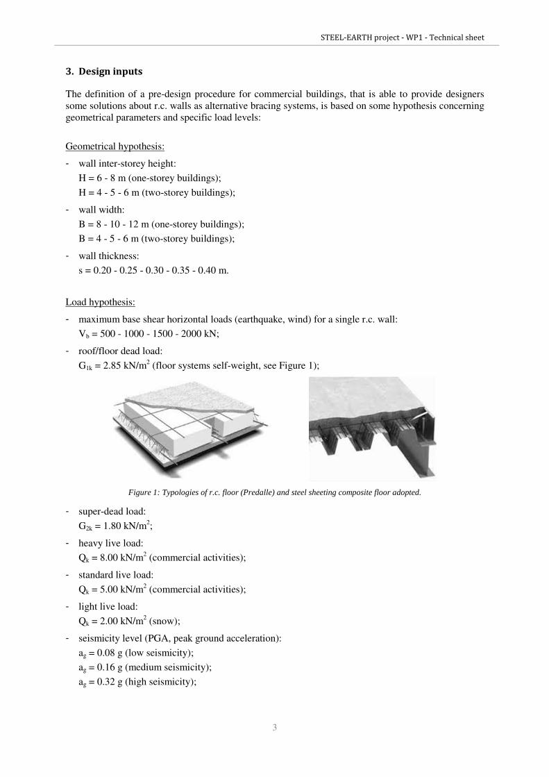
- roof/floor dead load:
G1k = 2.85 kN/m2 (floor systems self-weight, see Figure 1);
Figure 1: Typologies of r.c. floor (Predalle) and steel sheeting composite floor adopted.
- super-dead load:
G2k = 1.80 kN/m2;
- heavy live load:
Qk = 8.00 kN/m2 (commercial activities);
- standard live load:
Qk = 5.00 kN/m2 (commercial activities);
- light live load:
Qk = 2.00 kN/m2 (snow);
- seismicity level (PGA, peak ground acceleration):
ag = 0.08 g (low seismicity);
ag = 0.16 g (medium seismicity);
ag = 0.32 g (high seismicity);

STEEL-EARTH project - WP1 - Technical sheet
4
- r.c. walls are designed to resist both seismic and wind actions, assuming four different distributions
of the storey forces (distributions A, B, C, D, as explained in Figure 2). In the case of wind, the
base shear was distributed so that the force applied at the first storey is twice the one applied at the
roof level; in the case of seismic actions, by assuming the first vibration mode to be linear, the base
shear was distributed according to the following formulas (where M represents storey seismic
mass):
⋅⋅+⋅
⋅=
HMHM
HMVF b
21
11
2
⋅⋅+⋅
⋅⋅=
HMHM
HMVF b
21
22
2
2
Figure 2: Distribution of horizontal forces.

STEEL-EARTH project - WP1 - Technical sheet
5
4. Specific design concept
The definition of the mentioned pre-design method for r.c. walls as alternative bracing systems in steel
commercial buildings is based especially on some hypothesis concerning the idealization of the
structural behavior:
- simplified static schemes, obtained by extracting substructures with lower complexity but still able
to describe the behavior of the whole structure;
- substructures are regular in plant and in elevation, in terms both of the distribution of seismic
masses and stiffness;
- floor systems, columns and walls are designed separately considering vertical loads for the first two
and horizontal actions (seismic and wind actions) for the third (see Figure 3);
Figure 3: Decoupling of vertical and horizontal loads.
- floor systems are supposed as rigid diaphragms;
- foundation structures are considered and modeled as ideal rigid constraints;
- linear elastic analyses;
- static seismic analyses to pre-design ductile walls (ULS), simplified dynamic seismic analyses to
give an estimation about influence area/wall (considering lumped masses for each storey);
- overturning vibration modes are avoided by technical joints (gaps between architectural modules)
and a symmetrical disposition of the walls;
- ductile walls are uncoupled (i.e. C or L plan shapes for staircases);
- shear wall deformation is taken into account through a refined wall stiffness model (Timoshenko
model);
- limitations imposed by Eurocodes are considered in order to obtain structural performances
consistent with standard provisions.

STEEL-EARTH project - WP1 - Technical sheet
6
5. Design methodology
In order to obtain the minimum number of seismic-resistant walls, able to withstand assigned base
shears Vb and given a specific commercial building area, the following procedure is adopted.
The first vibration mode is assumed to be linear, consistently with the previous storey force
distributions adopted, and may be expressed as:
= 1......
1
n
i
naT
i = 1, ..., n (storey number).
Being K the translational stiffness matrix of the walls and M the mass matrix corresponding to a unit
area, the fundamental period T of the system can be estimated from the expression:
AKaa
MaaT ⋅
⋅
⋅⋅= π2
where A is the unknown wall influence area.
The influence area A of the single wall may be evaluated by solving the following nonlinear equation,
obtained by equating the assigned Vb to the base shear expected:
( )( )TS
Maa
MraAV db ⋅
⋅
⋅⋅=
2
where Sd is the design spectrum.
This approach is valid only for type “A”, “C” and “D” distribution of static forces (see Figure 4), in
which base shear is due to seismic actions; for distribution type “B” the forces are originated by wind
and the analysis the influence area A of the single wall is unpredictable because it requires knowing
the exact form of the building and the surfaces exposed to wind. The obtained results are referred to
the design spectra suggested by Eurocode 8 for soil Type B.
Figure 4: Simplified approach to estimate the influence area A of a single wall.
STEEL-EARTH project - WP1 - Technical sheet
7
Then, to sum up, the input steps that a designer has to follow are:
a) fixing the maximum base shear horizontal loads (earthquake, wind) for a single r.c. wall;
b) choosing the intensity of live load applied to commercial building structures (heavy, standard, light
live load);
c) defining the site seismicity level (PGA, peak ground acceleration);
d) assuming a distribution of the storey forces (A, B, C or D) with reference to the numbers of the
stories and the nature of actions (wind or seismic);
e) fixing the ductility class of the structure (DCH and DCM for dissipative structures, DCL for r.c.
structures that does not dissipate energy under cyclic loads generated by an earthquake);
f) estimation of behavior factor (q) of the structure with reference to ductility class and geometrical
properties of the r.c. wall (storey height, width, thickness).
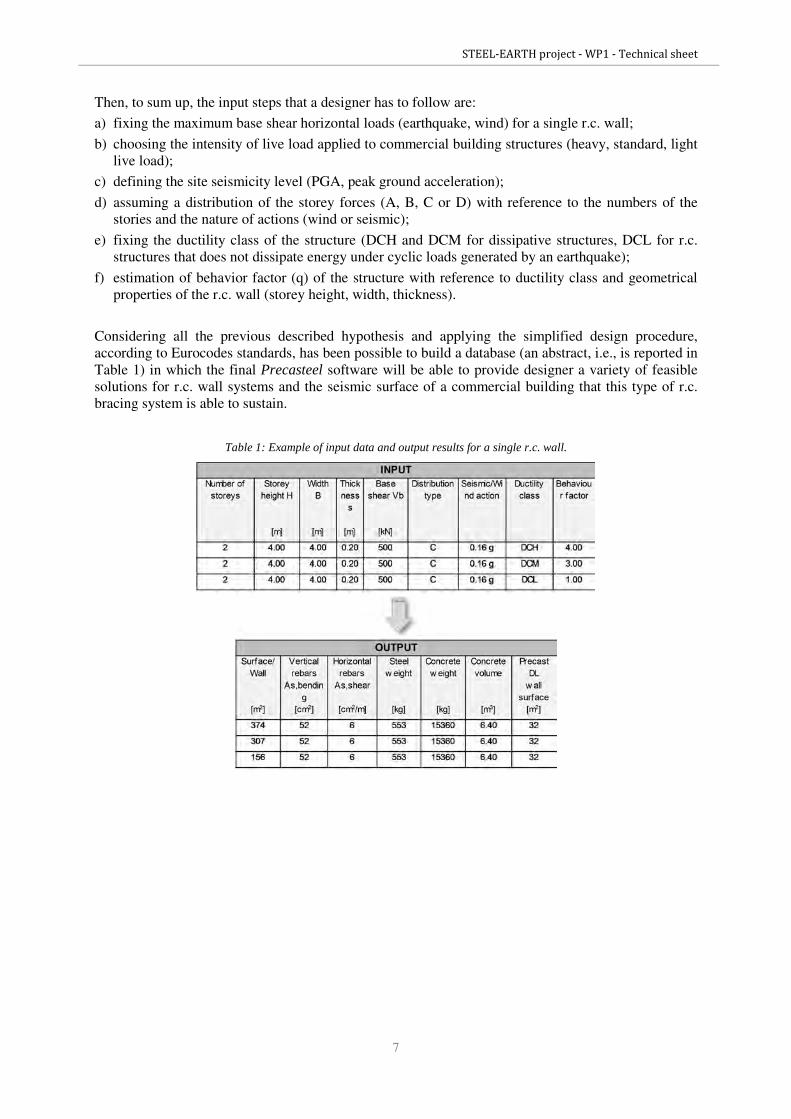
Considering all the previous described hypothesis and applying the simplified design procedure,
according to Eurocodes standards, has been possible to build a database (an abstract, i.e., is reported in
Table 1) in which the final Precasteel software will be able to provide designer a variety of feasible
solutions for r.c. wall systems and the seismic surface of a commercial building that this type of r.c.
bracing system is able to sustain.
Table 1: Example of input data and output results for a single r.c. wall.
STEEL-EARTH project - WP1 - Technical sheet
8
6. Details
Pre-design procedure of r.c. walls as bracing systems is easy, intuitive and fast, also in the definition
of the structural details suggested and prescribed by Eurocodes, in particular:
- Eurocode 8 for details about critical regions and confined zones of the walls for ductility classes
DCH and DCM;
- Eurocode 2 for details about low dissipative r.c. structures (DCL) or isolated structures by specific
devices.
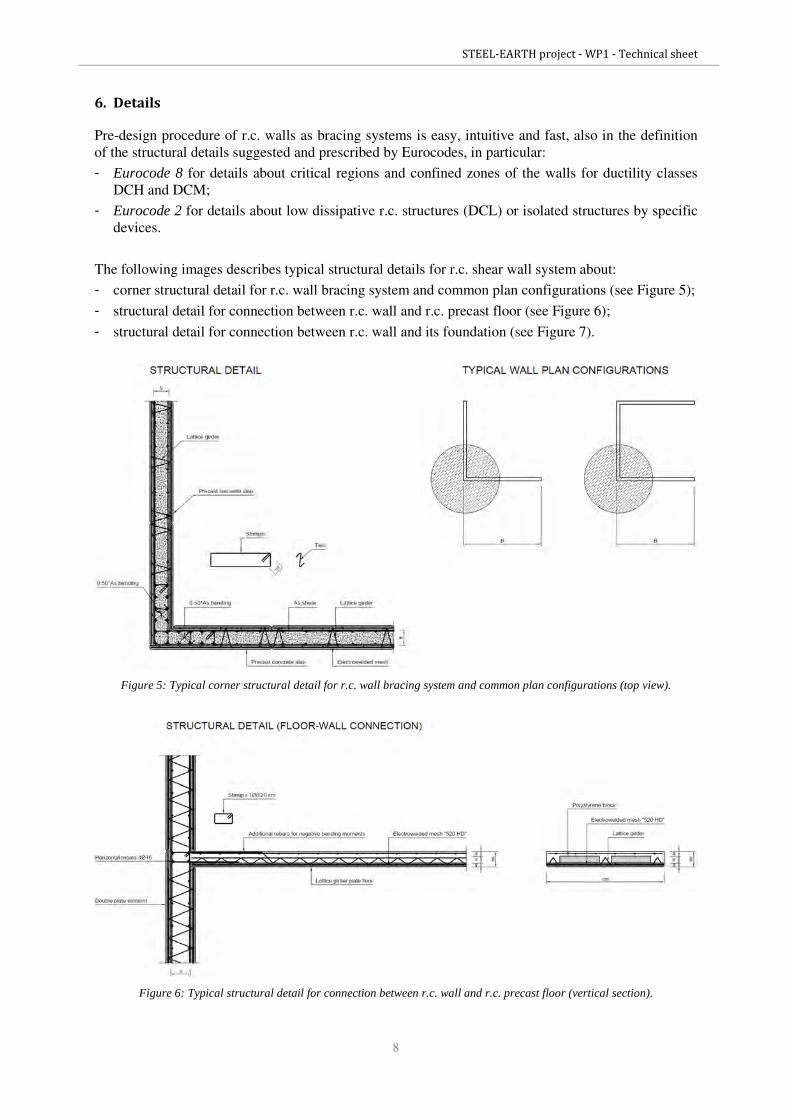
The following images describes typical structural details for r.c. shear wall system about:
- corner structural detail for r.c. wall bracing system and common plan configurations (see Figure 5);
- structural detail for connection between r.c. wall and r.c. precast floor (see Figure 6);
- structural detail for connection between r.c. wall and its foundation (see Figure 7).
Figure 5: Typical corner structural detail for r.c. wall bracing system and common plan configurations (top view).
Figure 6: Typical structural detail for connection between r.c. wall and r.c. precast floor (vertical section).
STEEL-EARTH project - WP1 - Technical sheet
9
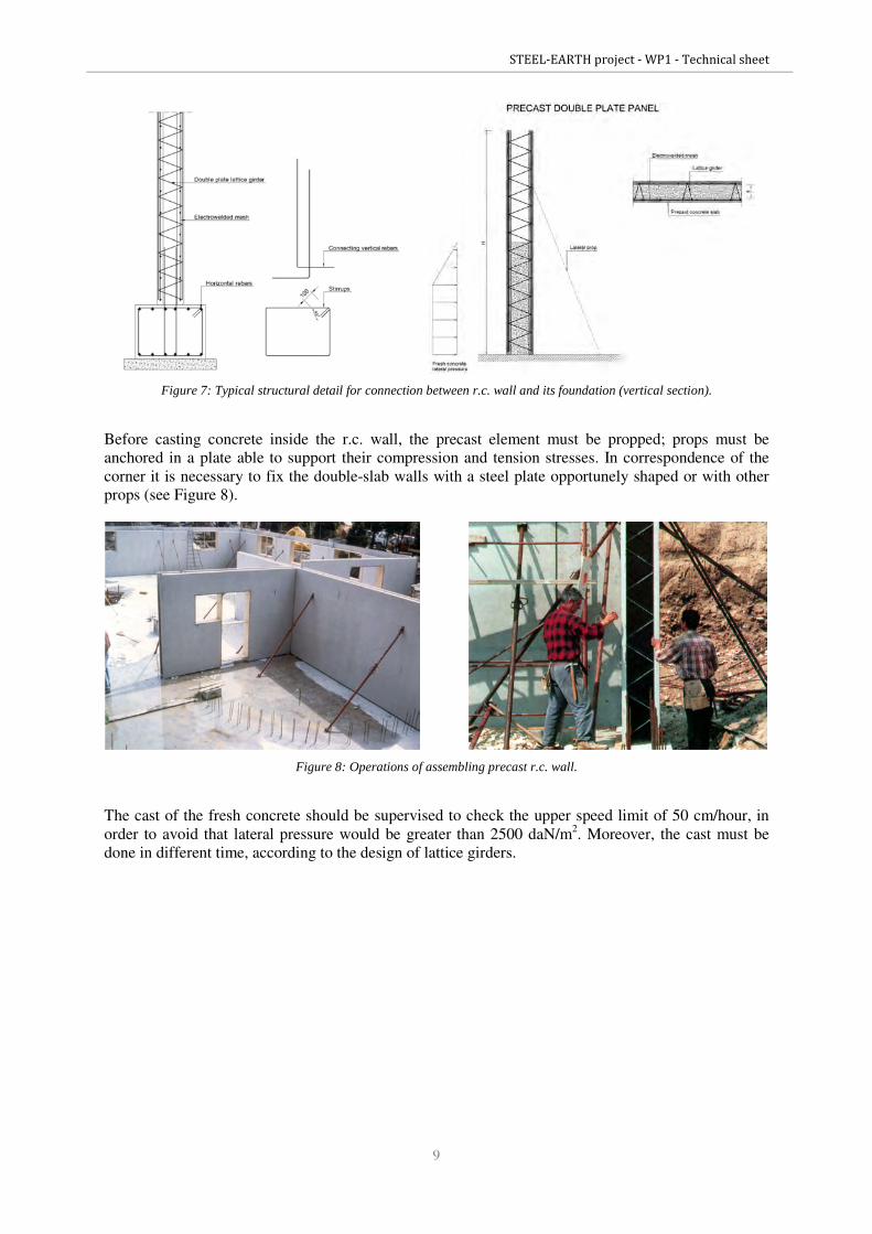
Figure 7: Typical structural detail for connection between r.c. wall and its foundation (vertical section).
Before casting concrete inside the r.c. wall, the precast element must be propped; props must be
anchored in a plate able to support their compression and tension stresses. In correspondence of the
corner it is necessary to fix the double-slab walls with a steel plate opportunely shaped or with other
props (see Figure 8).
Figure 8: Operations of assembling precast r.c. wall.
The cast of the fresh concrete should be supervised to check the upper speed limit of 50 cm/hour, in
order to avoid that lateral pressure would be greater than 2500 daN/m2. Moreover, the cast must be
done in different time, according to the design of lattice girders.

STEEL-EARTH project - WP1 - Technical sheet
10
For what concerns structural details about connections between the main steel structure (beams,
columns) and r.c. walls, there are two possible ways of detailing:
Connection decoupling horizontal and vertical loads
In this case we need an additional auxiliary beam, that transfers gravity loads towards the main steel
columns, so that we can connect our r.c. bracing system to the steel frame decoupling vertical and
horizontal loads (see Figure 9).
Figure 9: Typical connection between steel structure and r.c. walls, decoupling horizontal and vertical loads (top view).
Connection for both horizontal and vertical loads
In this case we don’t need an additional auxiliary beam and we can connect directly our r.c. bracing
system to the steel frame; then, it is possible for the walls support even vertical loads without
compromise their seismic behaviour (see Figure 10).
Figure 10: Typical connection between steel structure and r.c. walls for both horizontal and vertical loads.
Connections between steel structure (beams, columns) and r.c. walls as bracing systems could be
realized in an easy way by chemical or mechanical anchors, after the erection of the r.c. structure.
Another way to realize this kind of joints is the classical bolted connection, shaped and included in the
formwork before the concrete pour. If the main structure is isolated by dissipative devices, at each
floor there are specific steel joints to prevent hammering between wall systems and floor structures.
STEEL-EARTH project - WP1 - Technical sheet
11
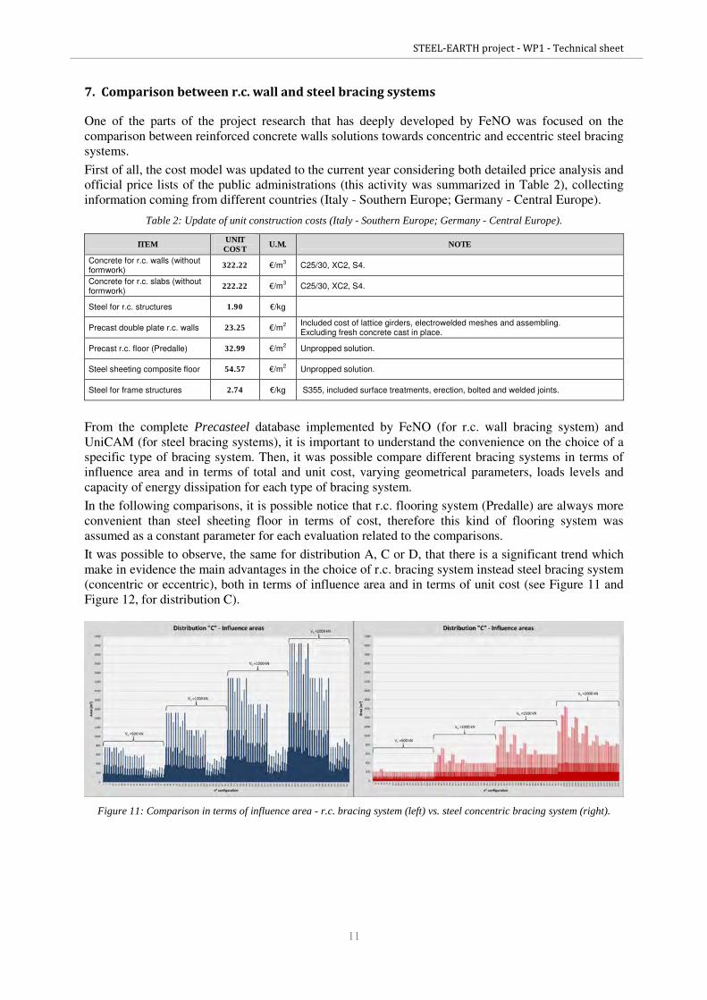
7. Comparison between r.c. wall and steel bracing systems
One of the parts of the project research that has deeply developed by FeNO was focused on the
comparison between reinforced concrete walls solutions towards concentric and eccentric steel bracing
systems.
First of all, the cost model was updated to the current year considering both detailed price analysis and
official price lists of the public administrations (this activity was summarized in Table 2), collecting
information coming from different countries (Italy - Southern Europe; Germany - Central Europe).
Table 2: Update of unit construction costs (Italy - Southern Europe; Germany - Central Europe).
ITEM UNIT
COST U.M. NOTE
Concrete for r.c. walls (without formwork)
322.22 €/m3 C25/30, XC2, S4.
Concrete for r.c. slabs (without formwork)
222.22 €/m3 C25/30, XC2, S4.
Steel for r.c. structures 1.90 €/kg
Precast double plate r.c. walls 23.25 €/m2
Included cost of lattice girders, electrowelded meshes and assembling. Excluding fresh concrete cast in place.
Precast r.c. floor (Predalle) 32.99 €/m2 Unpropped solution.
Steel sheeting composite floor 54.57 €/m2 Unpropped solution.
Steel for frame structures 2.74 €/kg S355, included surface treatments, erection, bolted and welded joints.
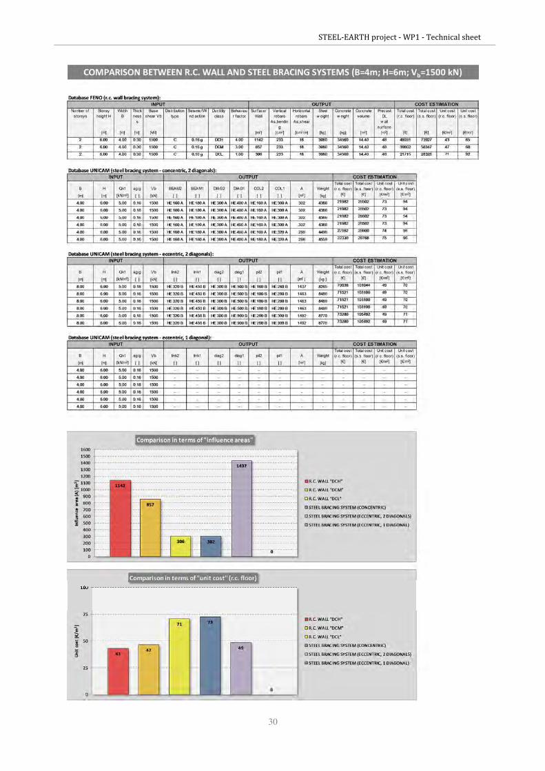
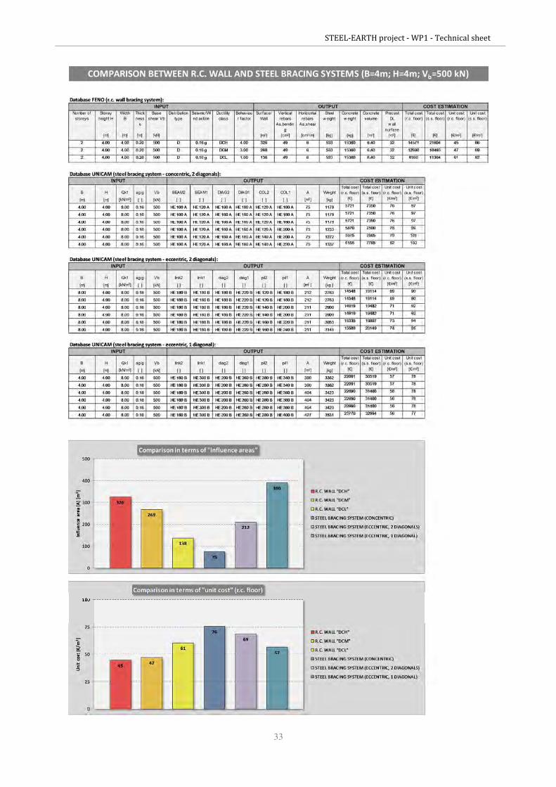
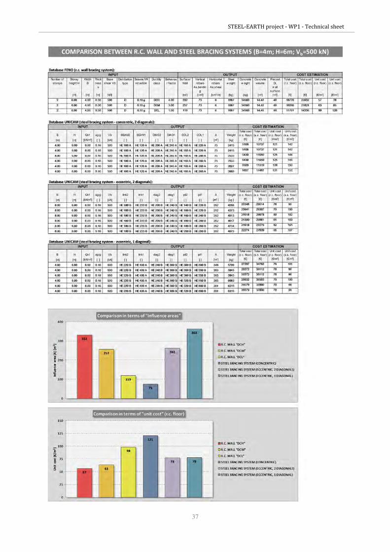
From the complete Precasteel database implemented by FeNO (for r.c. wall bracing system) and
UniCAM (for steel bracing systems), it is important to understand the convenience on the choice of a
specific type of bracing system. Then, it was possible compare different bracing systems in terms of
influence area and in terms of total and unit cost, varying geometrical parameters, loads levels and
capacity of energy dissipation for each type of bracing system.
In the following comparisons, it is possible notice that r.c. flooring system (Predalle) are always more
convenient than steel sheeting floor in terms of cost, therefore this kind of flooring system was
assumed as a constant parameter for each evaluation related to the comparisons.
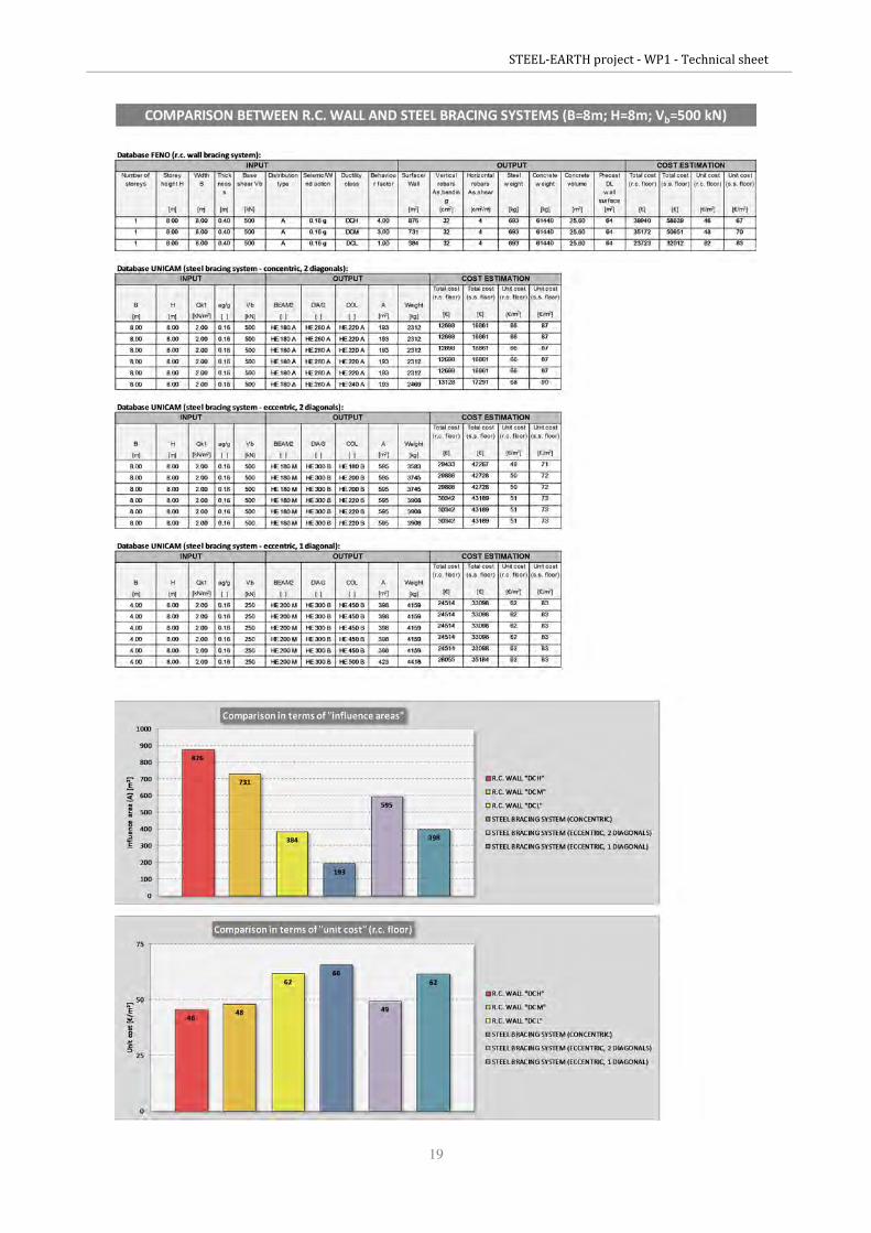
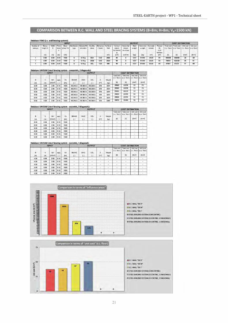
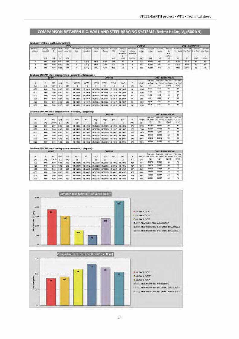
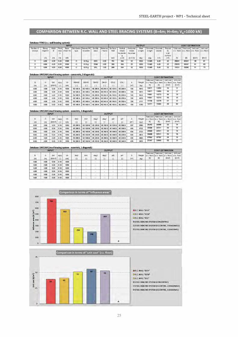
It was possible to observe, the same for distribution A, C or D, that there is a significant trend which
make in evidence the main advantages in the choice of r.c. bracing system instead steel bracing system
(concentric or eccentric), both in terms of influence area and in terms of unit cost (see Figure 11 and
Figure 12, for distribution C).
Figure 11: Comparison in terms of influence area - r.c. bracing system (left) vs. steel concentric bracing system (right).

STEEL-EARTH project - WP1 - Technical sheet
12
Figure 12: Comparison in terms of unit cost - r.c. bracing system (top) vs. steel concentric bracing system (bottom).
Moreover, comparing all the possible configurations for r.c. and steel bracing system, it is worth
noticing that steel bracing systems do not always resist in the complete range of shear base force Vb =
500÷2000 kN, but they are often limited on the upper forces due to design limits in terms of geometry
of the commercial steel profiles.
To confirm what FeNO noticed and discovered about the general convenience in the choice of r.c. wall
bracing system instead of steel bracing system (concentric or eccentric), in the following Table 3 is
exposed the activity of database sampling and comparison results (extracting 72 cases on a population
of 972 configurations; see Annex 1, 2, 3 for more extended and complete evaluations) finalized to give
an estimation about the mentioned convenience. This activity of database sampling was conducted
fixing some parameter about geometry and load levels, to evaluate the most representative bracing
configurations:
- wall inter-storey height:
H = 6 - 8 m (one-storey buildings);
H = 4 - 6 m (two-storey buildings);
- wall width:
B = 8 m (one-storey buildings);
B = 4 m (two-storey buildings);
- seismicity level (PGA, peak ground acceleration):
ag = 0.16 g (medium seismicity).
STEEL-EARTH project - WP1 - Technical sheet
13
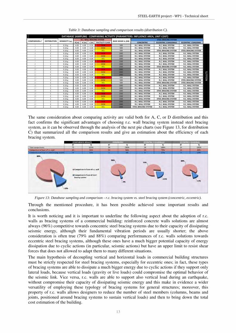
Table 3: Database sampling and comparison results (distribution C).
DATABASE SAMPLING - COMPARING ACTIVITY (PARAMETERS: INFLUENCE AREA, UNIT COST)
COMPARISON n° DISTRIBUTION SEISMICITY (ag) R.C. WALL BRACING SYSTEM
BASE SHEAR Vb [kN] STEEL BRACING SYSTEM
B [m] H [m] s [m] DUCTILITY CLASS CONCENTRIC ECCENTRIC 2 DIAGONALS ECCENTRIC 1 DIAGONAL
1 C 0.16 g 4.00 4.00 0.20 DCH 500 R.C. WALL SYSTEM R.C. WALL SYSTEM R.C. WALL SYSTEM
RE
SU
LT
S
2 C 0.16 g 4.00 4.00 0.20 DCM 500 R.C. WALL SYSTEM R.C. WALL SYSTEM R.C. WALL SYSTEM
3 C 0.16 g 4.00 4.00 0.20 DCL 500 R.C. WALL SYSTEM STEEL BRACING SYSTEM STEEL BRACING SYSTEM
4 C 0.16 g 4.00 4.00 0.20 DCH 1000 R.C. WALL SYSTEM R.C. WALL SYSTEM R.C. WALL SYSTEM
5 C 0.16 g 4.00 4.00 0.20 DCM 1000 R.C. WALL SYSTEM R.C. WALL SYSTEM R.C. WALL SYSTEM
6 C 0.16 g 4.00 4.00 0.20 DCL 1000 R.C. WALL SYSTEM R.C. WALL SYSTEM R.C. WALL SYSTEM
7 C 0.16 g 4.00 4.00 0.20 DCH 1500 R.C. WALL SYSTEM R.C. WALL SYSTEM R.C. WALL SYSTEM
8 C 0.16 g 4.00 4.00 0.20 DCM 1500 R.C. WALL SYSTEM R.C. WALL SYSTEM R.C. WALL SYSTEM
9 C 0.16 g 4.00 4.00 0.20 DCL 1500 R.C. WALL SYSTEM STEEL BRACING SYSTEM R.C. WALL SYSTEM
10 C 0.16 g 4.00 4.00 0.20 DCH 2000 R.C. WALL SYSTEM R.C. WALL SYSTEM R.C. WALL SYSTEM
11 C 0.16 g 4.00 4.00 0.20 DCM 2000 R.C. WALL SYSTEM R.C. WALL SYSTEM R.C. WALL SYSTEM
12 C 0.16 g 4.00 4.00 0.20 DCL 2000 R.C. WALL SYSTEM R.C. WALL SYSTEM R.C. WALL SYSTEM
13 C 0.16 g 4.00 6.00 0.30 DCH 500 R.C. WALL SYSTEM R.C. WALL SYSTEM R.C. WALL SYSTEM
14 C 0.16 g 4.00 6.00 0.30 DCM 500 R.C. WALL SYSTEM R.C. WALL SYSTEM STEEL BRACING SYSTEM
15 C 0.16 g 4.00 6.00 0.30 DCL 500 R.C. WALL SYSTEM STEEL BRACING SYSTEM STEEL BRACING SYSTEM
16 C 0.16 g 4.00 6.00 0.30 DCH 1000 R.C. WALL SYSTEM R.C. WALL SYSTEM R.C. WALL SYSTEM
17 C 0.16 g 4.00 6.00 0.30 DCM 1000 R.C. WALL SYSTEM R.C. WALL SYSTEM R.C. WALL SYSTEM
18 C 0.16 g 4.00 6.00 0.30 DCL 1000 R.C. WALL SYSTEM STEEL BRACING SYSTEM R.C. WALL SYSTEM
19 C 0.16 g 4.00 6.00 0.30 DCH 1500 R.C. WALL SYSTEM R.C. WALL SYSTEM R.C. WALL SYSTEM
20 C 0.16 g 4.00 6.00 0.30 DCM 1500 R.C. WALL SYSTEM R.C. WALL SYSTEM R.C. WALL SYSTEM
21 C 0.16 g 4.00 6.00 0.30 DCL 1500 R.C. WALL SYSTEM STEEL BRACING SYSTEM R.C. WALL SYSTEM
22 C 0.16 g 4.00 6.00 0.30 DCH 2000 R.C. WALL SYSTEM R.C. WALL SYSTEM R.C. WALL SYSTEM
23 C 0.16 g 4.00 6.00 0.30 DCM 2000 R.C. WALL SYSTEM R.C. WALL SYSTEM R.C. WALL SYSTEM
24 C 0.16 g 4.00 6.00 0.30 DCL 2000 STEEL BRACING SYSTEM R.C. WALL SYSTEM R.C. WALL SYSTEM
The same consideration about comparing activity are valid both for A, C, or D distribution and this
fact confirms the significant advantages of choosing r.c. wall bracing system instead steel bracing
system, as it can be observed through the analysis of the next pie charts (see Figure 13, for distribution
C) that summarized all the comparison results and give an estimation about the efficiency of each
bracing system.
Figure 13: Database sampling and comparison - r.c. bracing system vs. steel bracing system (concentric, eccentric).
Through the mentioned procedure, it has been possible achieved some important results and
conclusions.
It is worth noticing and it is important to underline the following aspect about the adoption of r.c.
walls as bracing systems of a commercial building: reinforced concrete walls solutions are almost
always (96%) competitive towards concentric steel bracing systems due to their capacity of dissipating
seismic energy, although their fundamental vibration periods are usually shorter; the above
consideration is often true (79% and 88%) comparing performances of r.c. walls solutions towards
eccentric steel bracing systems, although these ones have a much bigger potential capacity of energy
dissipation due to cyclic actions (in particular, seismic actions) but have an upper limit to resist shear
forces that does not allowed to adapt them to many different situations.
The main hypothesis of decoupling vertical and horizontal loads in commercial building structures
must be strictly respected for steel bracing systems, especially for eccentric ones; in fact, these types
of bracing systems are able to dissipate a much bigger energy due to cyclic actions if they support only
lateral loads, because vertical loads (gravity or live loads) could compromise the optimal behavior of
the seismic link. Vice versa, r.c. walls are able to support also vertical load during an earthquake,
without compromise their capacity of dissipating seismic energy and this make in evidence a wider
versatility of employing these typology of bracing systems for general structures; moreover, this
property of r.c. walls allows designers to reduce the number of steel members (columns, beams and
joints, positioned around bracing systems to sustain vertical loads) and then to bring down the total
cost estimation of the building.
STEEL-EARTH project - WP1 - Technical sheet
14
ANNEX 1
COMPARISON BETWEEN R.C. WALL AND STEEL BRACING SYSTEMS
Distribution “A”

STEEL-EARTH project - WP1 - Technical sheet
15

STEEL-EARTH project - WP1 - Technical sheet
16
STEEL-EARTH project - WP1 - Technical sheet
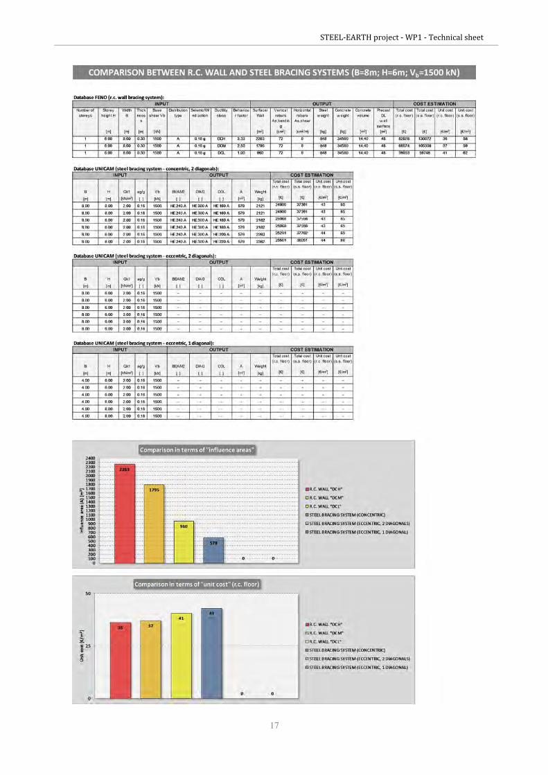
17

STEEL-EARTH project - WP1 - Technical sheet
18
STEEL-EARTH project - WP1 - Technical sheet
19

STEEL-EARTH project - WP1 - Technical sheet
20
STEEL-EARTH project - WP1 - Technical sheet
21

STEEL-EARTH project - WP1 - Technical sheet
22

STEEL-EARTH project - WP1 - Technical sheet
23
ANNEX 2
COMPARISON BETWEEN R.C. WALL AND STEEL BRACING SYSTEMS
Distribution “C”
STEEL-EARTH project - WP1 - Technical sheet
24
STEEL-EARTH project - WP1 - Technical sheet
25

STEEL-EARTH project - WP1 - Technical sheet
26

STEEL-EARTH project - WP1 - Technical sheet
27

STEEL-EARTH project - WP1 - Technical sheet
28

STEEL-EARTH project - WP1 - Technical sheet
29
STEEL-EARTH project - WP1 - Technical sheet
30

STEEL-EARTH project - WP1 - Technical sheet
31

STEEL-EARTH project - WP1 - Technical sheet
32
ANNEX 3
COMPARISON BETWEEN R.C. WALL AND STEEL BRACING SYSTEMS
Distribution “D”
STEEL-EARTH project - WP1 - Technical sheet
33

STEEL-EARTH project - WP1 - Technical sheet
34

STEEL-EARTH project - WP1 - Technical sheet
35

STEEL-EARTH project - WP1 - Technical sheet
36
STEEL-EARTH project - WP1 - Technical sheet
37

STEEL-EARTH project - WP1 - Technical sheet
38

STEEL-EARTH project - WP1 - Technical sheet
39

STEEL-EARTH project - WP1 - Technical sheet
40