Embed Size (px)
Citation preview

Item #33273
4 X 4 X 6 240 VOLT
POWDER COATING BOOTH INSTRUCTIONS

2 Eastwood Technical Assistance: 800.343.9353 >> [email protected]
The HOTCOAT POWDER COATING OVEN is a full-sized commercial unit designed for professional powder coating shops but is an excellent addition for any well-equipped home-based business. A highly efficient, 3 heating element system requires readily available 220 Volt AC power at only 39 Amps and requires no outside venting for use anywhere convenience. Generous interior dimensions with quick temperature ramp-up and recovery allow for rapid production turnaround times.
SPECIFICATIONSHeating Element Power Requirements: 240 Volt AC, 60Hz, 39-Amp, 8,500 Watt, Single Phase
Fan Power Requirement: 120 Volt AC, 60Hz, 6Amp
Interior Dimensions: 68.5” [1.73m] high x 40.5” [1.02m] wide x 44.5” [1.13m] deep (71 cubic feet) [2 cubic meters]
Exterior Dimensions: 72-1/2” [1.84m] high x 48-1/8” [1.2m] wide x 48-1/4” [1.2m] deep (Cabinet only, no external appendages)
READ INSTRUCTIONS • Thoroughly read and understand these product instructions before using the Oven.
• Keep these product instructions for future reference.
FIRE OR EXPLOSION HAZARD!• Never apply powder coating in or in front of an operating oven. Always operate the oven in a well–ventilated area.
FIRE HAZARD• Never allow the Oven to operate unattended. Always disconnect Oven from the electrical power supply before leaving it unattended.
ELECTRICAL SHOCK HAZARD!• Never use the HotCoat Oven outdoors when it is raining or in wet or damp areas, as it may cause an electric shock.
• Connect only to a 240VAC, 60Hz, 40 Amp circuit meeting all applicable local electrical codes.
ENTRAPMENT HAZARD!• DO NOT allow children, persons or animals access to the oven. The door is latched from the Outside Only and cannot be unlatched from
the inside!
DANGER indicates a hazardous situation which, if not avoided, will result in death or serious injury.
WARNING indicates a hazardous situation which, if not avoided, could result in death or serious injury.
CAUTION indicates a hazardous situation which, if not avoided, could result in minor or moderate injury.
NOTICE is used to address practices not related to personal injury.
SAFETY INFORMATIONThe following explanations are displayed in this manual, on the labeling, and on all other information provided with this product:

To order parts and supplies: 800.343.9353 >> eastwood.com 3
INJURY HAZARD!• This Oven must be located only on a flat, level and secure surface. Do not locate the Oven on an elevated platform, table, bench, roof or
other non-secure location
• DO NOT attempt to stand or sit on the Oven Cabinet. It may cause collapse resulting in serious injury.
BURN HAZARD• The Oven generates high internal heat during operation. All interior walls and door surfaces will reach 400 F [204 C] during operation.
Use extreme caution when Oven is open to avoid burns.
• Always wear appropriate heat-resistant work gloves and protective clothing while placing items in or removing items from Oven.
• Allow sufficient time for cooling before touching parts.
FIRE HAZARD!• DO NOT use the Oven as a storage area. Items placed inside may be forgotten and cause a fire if Oven is started.
• DO NOT store items on top of the Oven cabinet.
• To provide proper ventilation for cooling and prevent overheating, the Oven must be placed at a minimum of 3’ (31 cm) from the nearest
wall, in a well–ventilated area. DO NOT allow the ventilation fan intake to be blocked or possible permanent damage could occur.
OVEN SITE LOCATION
• Select an area with adequate ventilation and air circulation. A minimum of 3’ [90 cm] of free space must be maintained around all sides and above the Oven. This is to allow for adequate ventilation and to allow room for a person to access all sides for maintenance purposes. Do not store objects behind or along the Oven.
• The temperature environment for proper operation must be between 32°F and 120°F [0°C and 49°C]. The Oven may not function properly in excessive ambient temperature conditions.
• Keep all lines, cords, and hoses out of the path between the powder application station and the Oven door to avoid a potential tripping hazard or where damage could occur.
FIRE HAZARD! Install ONLY on a solid, level, bare and clean concrete floor surface. DO NOT install over painted or coated concrete, tile, vinyl,
asphalt wood or any other material that will be melted or ignited by exposure to high temperatures transmitted through the floor.
EXPLOSION HAZARD! The oven must be installed in an area that is free from flammable and explosive dust, fumes and gasses.
The Hot Coat M446 Powdercoating Oven generates heat during operation. Sufficient space must be provided around the unit for
exterior cabinet cooling and ventilation air circulation.

4 Eastwood Technical Assistance: 800.343.9353 >> [email protected]
OVEN SET-UP• Prepare Oven to accept coated parts:
- The Use of an Eastwood # 33274 Rolling Rack or Equivalent is Required – Some means of support is required for parts placement in the oven. A Rolling Rack is the preferred method as parts may be placed on a grounded rack for coating and rolled into the Oven for curing. A built-in guide rail system is provided on the floor of the Oven for this purpose and to provide protection for the Heating Elements. As an alternative, a metal hanging rack may be fabricated for this purpose. NOTE: Any rolling or hanging rack MUST be constructed of materials able to withstand constant exposure to 400 F [204°C].
ELECTRICAL CONNECTION• 240 Volt, 60Hz, 50-amp, Single Phase voltage and amperage requirements.
• The 240 Volt wiring connections are made at the Upper Terminals of the Control Box.
• The voltage variation between the rated input voltage requirements and that of the actual input voltage supply must not exceed +/- 10%. If greater varia-tion exists, a step-up or step-down transformer must be installed.
• The power supply wiring must be adequately sized to prevent low voltage at the Oven. Low voltage will cause failure to reach temperature, and excessive tripping of circuit breakers. The wire gauge must be increased for longer wire runs to accommodate the increased resistance inherent in longer runs. Refer to the National Electric Code to determine the proper wire gauge for specific wire run lengths. Low voltage can also be caused by low supply voltage from the power company, or from other equipment running on the same line.
• For safety reasons, install a disconnect switch in the line from the electrical panel to the Oven within reach of the Oven. Alternatively, a dedicated 40 AMP 240 Volt outlet may be located within reach of the Oven.
• When the installed disconnect switch is off, or the unit unplugged from an outlet, all power to the Oven should be fully disconnected before any service or repairs are attempted.
All wiring must be done by a licensed electrician, in accordance with all National Electric Code, state and local requirements. For best performance, the Oven must be installed on a dedicated circuit, with circuit breaker or fuse protection.
When the Oven Control Power Switch (A) switch is ON, the Oven can start and stop automatically as it will be controlled by the Temperature Controller.
CONTROL PANEL FEATURES AND FUNCTIONS (FIG 1)
[A] Power Switch
[B] Heating Element Power Switch
[C] Circulating Fan Power Switch
[D] Temperature Controller
[E] Emergency STOP Switch – Cuts ALL Control Box Power when pushed in
FIG. 1
Before starting the Oven for the first time, the following check MUST be done:
• Check oven interior for foreign objects. Oven and Heating Elements must be clean and free from any packing material.
• Check surrounding area and oven exterior for any remaining packing materials or presence of any flammable items.
A
B
C
D
E

To order parts and supplies: 800.343.9353 >> eastwood.com 5
OVEN STARTUP1. Check that the Emergency STOP Button [E] is pulled out.
2. Turn on the POWER Switch [A] of the Control Panel. - Indicator lamp illuminates.
3. Set the HEAT Switch [B] of the Control Panel to “ON”. - The RED upper Digital Display [D] shows the initial Oven ambient temperature then quickly climbing. - The lower GREEN Digital Display shows “400” [D]. - Center indicator lamp illuminates.
4. Set the FAN Switch [C] of the Control Panel to “ON”. - Fan will run. Lower indicator lamp illuminates.
5. If any of the above functions are not performing, depress the STOP Button [E] immediately and determine cause.
6. When the correct function of Oven Controls has been verified, proceed to OVEN OPERATION.
OVEN OPERATION
FULL USE OF OVEN• Start Oven as described above.
• Allow Oven temperature to climb and reach 400°F (as indicated in the RED digi-tal display) [D] (FIG 2). This should require less than 20 minutes when starting with a 70°F ambient temperature.
The temperature can be overridden to a lower or higher set point (example 350°F/450°F) however after the power to the Temperature Controller [D] is shut off and turned on the next time, it will default back to 400°F.
The temperature cannot be overridden to exceed 450°F
TO OVERRIDE: - Press the (▲) Key on the Temperature Controller [D] to raise the temperature set
point then press the “SET” Key to lock it in.
- Press the (▼) Key Temperature Controller [D] to lower the temperature set point then press the “SET” Key to lock it in.
FIG. 2
The Oven may emit burning odors during the first use.
The Temperature Controller [D] is pre-set at the factory to go to and hold 400°F. Expect a +/- 6 F temperature fluctuation with the door kept closed and during powder cure.
MAINTENANCE• The oven walls and floor should be dusted and swept out carefully to remove
any loose powder that may have fallen off parts before the curing process. Use extreme care not to damage the Heating Elements.
• Always disconnect power at the main disconnect when Oven use is complete. DO NOT rely on simply setting Fan and Heating Element or Emergency Switches to off.
• Keep Oven Door closed and latched when not in use.
OVEN REPAIR
HEATING ELEMENT REPLACEMENT:
- With a #2 Philips screwdriver, remove the 3 retaining screws and pull the Heating Element straight out (FIG 3). The electrical connections are of the spade connector type and require no tools.
- Push the replacement terminals onto the spade terminals of the wires. Insulate with a fiberglass sleeve or High temperature tape.
- Push the wires and Heating Element ends into the holes until the metal flange is flush against the Oven wall.
- Make sure the Element is aligned and secure with the previously removed screws.
- Reconnect Oven power and test Heating Element.
6 Eastwood Technical Assistance: 800.343.9353 >> [email protected]
FIG. 3
FIG. 4
SHOCK HAZARD! DO NOT rely on shutting off Control Heating Element Switches or
Emergency Stop! Disconnect all power to the Oven. Before begin-ning, disconnect power at the breaker or power disconnect.
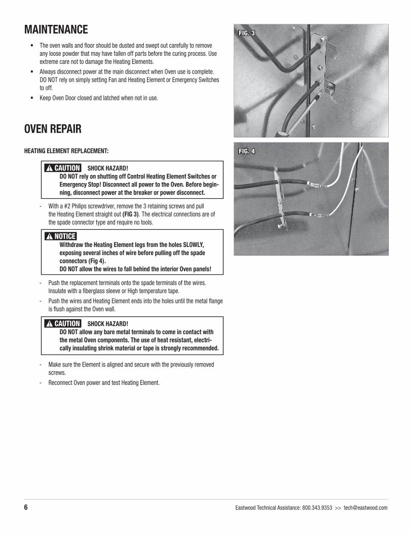
Withdraw the Heating Element legs from the holes SLOWLY, exposing several inches of wire before pulling off the spade connectors (Fig 4). DO NOT allow the wires to fall behind the interior Oven panels!
SHOCK HAZARD! DO NOT allow any bare metal terminals to come in contact with
the metal Oven components. The use of heat resistant, electri-cally insulating shrink material or tape is strongly recommended.

To order parts and supplies: 800.343.9353 >> eastwood.com 7
FAN REPLACEMENT - Disconnect all power to the Oven. Before beginning, disconnect power at the
breaker or power disconnect.
- Working from the inside of the Oven and using a Hex Key (Not Included) to loosen the setscrew, remove the Squirrel Cage Fan from the Motor Shaft (FIG 5).
- Remove the screws retaining the cover on the underside of the Fan Motor Housing, loosen the screws and remove the wire connection, spade lugs from the terminals (FIG 6).
- With a medium Philips screwdriver, remove the 3 retaining screws and pull the Fan Motor from the outside wall of the Oven (FIG 7).
- Insert the motor shaft through the hole in the Oven wall and secure with the previously removed screws.
- Reconnect the wire terminals to the motor connections and replace the cover.
- Working again from inside the Oven, insert the Squirrel Cage Fan into the hole while aligning the set-screw with the flat of the motor shaft.
- Make sure the Squirrel Cage Fan is flush and tighten the setscrew.
- Reconnect Oven power and test the Fan.
HEATING SWITCH CONTACTOR REPLACEMENT - Disconnect all power to the Oven. Before beginning, disconnect
power at the breaker or power disconnect.
- Loosen the screws retaining the cover of the Control Box and slide it up and off by the Keyhole Slots (FIG 8).
- Loosen and remove the terminal connections on the Heating Switch Contactor.
- Remove mounting screws and the Heating Element Contactor Switch (FIG 9). - Replace the Heating Element Contactor Switch.
- Reconnect the terminal connections.
- Replace the Cover.
- Reconnect Oven power and test Heating Elements.
SHOCK HAZARD! DO NOT rely on shutting off Control Heating Element Switches or
Emergency Stop!
FIG. 5
FIG. 6
FIG. 7
FIG. 8 FIG. 9
SHOCK HAZARD! DO NOT rely on shutting off Control Heating Element Switches or
Emergency Stop! Disconnect all power to the Oven. Before begin-ning, disconnect power at the breaker or power disconnect.

8 Eastwood Technical Assistance: 800.343.9353 >> [email protected]
FAN OR HEATING ELEMENT SWITCH REPLACEMENT- Disconnect all power to the Oven. Before beginning, disconnect power at the
breaker or power disconnect.
CAUTION! SHOCK HAZARD: DO NOT rely on shutting off Control Heating Element Switches or Emergency Stop! Disconnect all power to the Oven. Before begin-ning, disconnect power at the breaker or power disconnect
- Loosen the screws retaining the cover of the Control Box and slide it up and off by the Keyhole Slots (FIG 8).
- Loosen and remove the terminal connections on the Fan or Heating Element Switch.
- Unthread the flat retaining nut from the outside surface of the cover and remove the Fan or Heating Element Switch from the Control Box Cover (FIG 10).
- Replace the Fan or Heating Element Switch.
- Reconnect the terminal connections.
- Replace the Cover.
- Reconnect Oven power and test Fan or Heating Element Switch.
TEMPERATURE CONTROLLER REPLACEMENT- Disconnect all power to the Oven. Before beginning, disconnect power at the
breaker or power disconnect.
CAUTION! SHOCK HAZARD: DO NOT rely on shutting off Control Heating Element Switches or Emergency Stop! Disconnect all power to the Oven. Before begin-ning, disconnect power at the breaker or power disconnect.
- Loosen the screws retaining the cover of the Control Box and slide it up and off by the Keyhole Slots (Fig 8).
- Loosen and remove the terminal connections on the Temperature Controller (FIG 11).
- With a flat blade screwdriver, unlatch retainer and remove the Temperature Controller (FIG 12) from the Control Box Cover by pushing it through the front.
- Replace the Temperature Controller.
- Reconnect the terminal connections.
- Replace the Cover.
- Reconnect Oven power and test Temperature Controller.
DOOR GASKET REPLACEMENT- Oven must be off and fully cooled before beginning.
- Using a pencil, mark the cabinet frame at the edge of the Gasket. Also mark screw locations before removing (FIG 13).
- Loosen and remove the Phillips head screws attaching the Gasket to the Cabinet.
- Pull damaged gasket away.
- Set replacement Gasket against cabinet frame referring to the previous pencil marks.
- Using previously removed screws and referencing pencil marks, install the replacement Gasket.
FIG. 10
FIG. 11
FIG. 12
FIG. 13

To order parts and supplies: 800.343.9353 >> eastwood.com 9
DOOR HINGE ADJUSTMENTOver time and with frequent usage, the Door Hinges may begin to wear and allow the door to sag a small amount. This is generally evident by some latch misalignment and the lower right corner of the Door contacting the floor when being operated. They may be easily adjusted to restore proper fit.
- Oven must be off and fully cooled before beginning.
- With the Door closed and the latch open, measure the space between the lower left corner of the Door and the floor and note the dimension.
- Taking the noted dimension from the left side, add an additional 1/2 the amount for wedging height. For example: if the left door corner to floor is 1/2”, create a wedge of 3/4”.
Very slightly loosen the screws attaching the upper Hinge to the side of the cabinet.
- At the same time, have the assistant lift up on the right side of the door and insert the stacked material under the lower right front corner of the Door for support.
- Insert shim metal stock material between the upper Hinge and the cabinet and tighten screws.
- Remove the wedging material from under right front corner of the door, check for operation of Door and repeat above procedure, adding shim material if necessary.
Use only non-flammable metal shim stock material.
Do Not loosen all Hinge screws at once. Start at the upper Hinge, make adjustments and move to the lower Hinge as required.
The help of an assistant is strongly recommended for this procedure.
#6 sheetmetal screws are used. If screw holes in the Cabinet have become enlarged and will not tighten, #8 sheetmetal screws may be substituted.

To order parts and supplies: 800.343.9353 >> eastwood.com 11
PROBLEM CAUSE CORRECTION
GREEN Lamp Does Not Illuminate When Switch (A) is Set to “ON”
No Power Check 220 VAC, 60Hz, power source and connection to entire Oven unit.
Power supply circuit breaker to entire Oven is tripped Reset circuit breaker.
Emergency STOP Switch (E) is pushed in Pull Emergency STOP Switch (E) out.
Oven Controller (D) is faulty. Replace Oven Controller (D).
Heating Elements Fail To Heat
No Power Check 220 VAC, 60Hz, power source and connection to entire Oven unit.
Power supply circuit breaker to entire Oven is tripped Reset circuit breaker.
Emergency STOP Switch (E) is pushed in Pull Emergency STOP Switch (E) out.
A Heating Element is faulty. With all power disconnected, check for resistance in Heating Element. If open, replace Heating Element.
A Heating Switch Contactor is faulty Check for continuity of Contactor, If open, replace Heating Switch Contactor.
The Heat On Switch is faulty Check for continuity of Switch, If open, replace Heat On Switch.
Oven Controller (D) is faulty. Replace Oven Controller (D).
Oven Fails to Reach Curing Temperature
Input voltage too low Determine the cause of low input voltage condition or consult a licensed electrician for diagnosis.
Oven being operated in excessively low (under 32°F [0°C]) ambient temperature conditions
Do not operate Oven until ambient temperature conditions are favorable.
Oven Controller (D) is faulty Replace Oven Controller (D).
Heating Ele-ments Will Not Shut Off
A Heating Switch Contactor is faulty and stuck in the closed (ON) position. Disconnect Oven from power supply. Replace Heating Switch Contactor.
TROUBLESHOOTING AND DIAGNOSTICS

REPLACEMENT PARTS#32820 Heating Relay Contactor
#32821 Electrical Enclosure
#32822 High Temperature Wire
#32823 Distribution Terminal Block
#32824 Control Panel, On-Off Toggle Switch
#32825 Oven Heating Element
#32826 Emergency Stop Switch
#32827 2 Gauge Connection Wire
#32831 Oven Controller
#32832 Oven Door Seal
#32833 Oven Door Hinge
#32834 Circulation Fan Motor
#32835 Oven Door Latch
© Copyright 2020 Eastwood Automotive Group LLC 6/20 Instruction item #33273Q Rev 1
If you have any questions about the use of this product, please contact The Eastwood Technical Assistance Service Department: 800.343.9353 >> email: [email protected]
PDF version of this manual is available at eastwood.comThe Eastwood Company 263 Shoemaker Road, Pottstown, PA 19464, USA 800.343.9353 eastwood.com