Embed Size (px)
Citation preview
Epsilon 4User's GuideUser's Guide
Epsilon 4User's Guide
Page 1
EDITION NOTICE: 4023 001 16461, October 2017This is the original publication of Edition 1 of this document, to be used with theEpsilon 4 instrument.
ACKNOWLEDGMENTS
All registered and unregistered trademarks, domain names and copyrights hereinare the property of their respective owners.
DISCLAIMER
The information provided herein is supplied under a non-exclusive licenseauthorizing its use solely for and in conjunction with PANalytical's products.Although diligent care has been used to ensure that the information is accurate,nothing contained herein can be construed to imply any representation orwarranty as to the accuracy, currency or completeness of this information.
COPYRIGHT NOTICE
© 2017, PANalytical B.V., Almelo, The Netherlands
PANalytical B.V.Lelyweg 17602 EA, AlmeloThe NetherlandsTel: +31 546 534444Fax: +31 546 534598Internet: www.PANalytical.com
Page 2
General pages

Table of contentsChapter 1. Introduction. . . . . . . . . . . . . . . . . . . . . . . . . . . . . . . . . . . . . . . . . . . . . . . 7
1.1 General. . . . . . . . . . . . . . . . . . . . . . . . . . . . . . . . . . . . . . . . . . . . . . . . . . . . . . . 7
1.2 Intended use. . . . . . . . . . . . . . . . . . . . . . . . . . . . . . . . . . . . . . . . . . . . . . . . . . . 7
1.3 Recommended Skill Levels. . . . . . . . . . . . . . . . . . . . . . . . . . . . . . . . . . . . . . . . 7
Chapter 2. Safety. . . . . . . . . . . . . . . . . . . . . . . . . . . . . . . . . . . . . . . . . . . . . . . . . . . . . 9
2.1 Introduction to safety aspects. . . . . . . . . . . . . . . . . . . . . . . . . . . . . . . . . . . . . 9
2.1.1 Authorized personnel. . . . . . . . . . . . . . . . . . . . . . . . . . . . . . . . . . . . . . . 9
2.1.2 Safety guarantee. . . . . . . . . . . . . . . . . . . . . . . . . . . . . . . . . . . . . . . . . . . 9
2.1.3 Alerts and labels. . . . . . . . . . . . . . . . . . . . . . . . . . . . . . . . . . . . . . . . . . 10
2.2 Safety standards. . . . . . . . . . . . . . . . . . . . . . . . . . . . . . . . . . . . . . . . . . . . . . . 10
2.3 PANalytical's Approach. . . . . . . . . . . . . . . . . . . . . . . . . . . . . . . . . . . . . . . . . 11
2.4 User responsibilities. . . . . . . . . . . . . . . . . . . . . . . . . . . . . . . . . . . . . . . . . . . . 11
2.4.1 What to do in case of an emergency. . . . . . . . . . . . . . . . . . . . . . . . . . 12
2.5 General hazards. . . . . . . . . . . . . . . . . . . . . . . . . . . . . . . . . . . . . . . . . . . . . . . 13
2.5.1 Ionizing radiation. . . . . . . . . . . . . . . . . . . . . . . . . . . . . . . . . . . . . . . . . 13
2.5.2 Toxic material. . . . . . . . . . . . . . . . . . . . . . . . . . . . . . . . . . . . . . . . . . . . . 14
2.5.3 Flammable material. . . . . . . . . . . . . . . . . . . . . . . . . . . . . . . . . . . . . . . . 16
2.5.4 Earth leakage current. . . . . . . . . . . . . . . . . . . . . . . . . . . . . . . . . . . . . . 16
2.6 Safety measures. . . . . . . . . . . . . . . . . . . . . . . . . . . . . . . . . . . . . . . . . . . . . . . 16
2.6.1 HT keyswitch. . . . . . . . . . . . . . . . . . . . . . . . . . . . . . . . . . . . . . . . . . . . . 16
2.6.2 X-RAYS lamps. . . . . . . . . . . . . . . . . . . . . . . . . . . . . . . . . . . . . . . . . . . . . 16
2.6.3 Double independent safety loops. . . . . . . . . . . . . . . . . . . . . . . . . . . . 16
2.6.4 Xsafe. . . . . . . . . . . . . . . . . . . . . . . . . . . . . . . . . . . . . . . . . . . . . . . . . . . . 17
2.6.5 Safe use of the instrument. . . . . . . . . . . . . . . . . . . . . . . . . . . . . . . . . . 17
Chapter 3. System description. . . . . . . . . . . . . . . . . . . . . . . . . . . . . . . . . . . . . . . . . 21
3.1 Introduction. . . . . . . . . . . . . . . . . . . . . . . . . . . . . . . . . . . . . . . . . . . . . . . . . . 21
3.2 Location of components. . . . . . . . . . . . . . . . . . . . . . . . . . . . . . . . . . . . . . . . 21
3.3 Optical path. . . . . . . . . . . . . . . . . . . . . . . . . . . . . . . . . . . . . . . . . . . . . . . . . . 22
Chapter 4. Installation. . . . . . . . . . . . . . . . . . . . . . . . . . . . . . . . . . . . . . . . . . . . . . . 23
4.1 Introduction. . . . . . . . . . . . . . . . . . . . . . . . . . . . . . . . . . . . . . . . . . . . . . . . . . 23
4.2 Unpack the instrument. . . . . . . . . . . . . . . . . . . . . . . . . . . . . . . . . . . . . . . . . 23
4.2.1 Examine the external impact indicators. . . . . . . . . . . . . . . . . . . . . . . . 26
Page 3
4.3 Install the instrument. . . . . . . . . . . . . . . . . . . . . . . . . . . . . . . . . . . . . . . . . . . 26
4.4 Let the instrument become stable. . . . . . . . . . . . . . . . . . . . . . . . . . . . . . . . . 27
4.4.1 Do an X-ray leakage test. . . . . . . . . . . . . . . . . . . . . . . . . . . . . . . . . . . . 28
4.5 Install the software. . . . . . . . . . . . . . . . . . . . . . . . . . . . . . . . . . . . . . . . . . . . . 28
4.5.1 Install the USB driver. . . . . . . . . . . . . . . . . . . . . . . . . . . . . . . . . . . . . . . 29
4.6 Supply connections. . . . . . . . . . . . . . . . . . . . . . . . . . . . . . . . . . . . . . . . . . . . . 30
Chapter 5. Operate the instrument. . . . . . . . . . . . . . . . . . . . . . . . . . . . . . . . . . . . . 31
5.1 Introduction. . . . . . . . . . . . . . . . . . . . . . . . . . . . . . . . . . . . . . . . . . . . . . . . . . 31
5.2 Control panel. . . . . . . . . . . . . . . . . . . . . . . . . . . . . . . . . . . . . . . . . . . . . . . . . 31
5.2.1 POWER button and indicator. . . . . . . . . . . . . . . . . . . . . . . . . . . . . . . . 32
5.2.2 HT keyswitch and HT ENABLED indicator. . . . . . . . . . . . . . . . . . . . . . 32
5.2.3 LID LOCKED indicator. . . . . . . . . . . . . . . . . . . . . . . . . . . . . . . . . . . . . . 32
5.2.4 MEASURING indicator. . . . . . . . . . . . . . . . . . . . . . . . . . . . . . . . . . . . . . 32
5.3 Switch on the instrument. . . . . . . . . . . . . . . . . . . . . . . . . . . . . . . . . . . . . . . . 32
5.4 Switch off the instrument. . . . . . . . . . . . . . . . . . . . . . . . . . . . . . . . . . . . . . . 33
5.5 Backup the userdata. . . . . . . . . . . . . . . . . . . . . . . . . . . . . . . . . . . . . . . . . . . . 33
Chapter 6. Measure samples. . . . . . . . . . . . . . . . . . . . . . . . . . . . . . . . . . . . . . . . . . 35
6.1 Measurement overview. . . . . . . . . . . . . . . . . . . . . . . . . . . . . . . . . . . . . . . . . 35
6.2 Sample types. . . . . . . . . . . . . . . . . . . . . . . . . . . . . . . . . . . . . . . . . . . . . . . . . . 36
6.3 Sample loading. . . . . . . . . . . . . . . . . . . . . . . . . . . . . . . . . . . . . . . . . . . . . . . . 36
6.4 Sample tray. . . . . . . . . . . . . . . . . . . . . . . . . . . . . . . . . . . . . . . . . . . . . . . . . . . 37
6.5 Load samples. . . . . . . . . . . . . . . . . . . . . . . . . . . . . . . . . . . . . . . . . . . . . . . . . . 37
6.6 Measure large samples. . . . . . . . . . . . . . . . . . . . . . . . . . . . . . . . . . . . . . . . . . 39
Chapter 7. User maintenance. . . . . . . . . . . . . . . . . . . . . . . . . . . . . . . . . . . . . . . . . . 43
7.1 Introduction. . . . . . . . . . . . . . . . . . . . . . . . . . . . . . . . . . . . . . . . . . . . . . . . . . 43
7.2 Test of the safety integrity. . . . . . . . . . . . . . . . . . . . . . . . . . . . . . . . . . . . . . . 43
7.3 Clean the instrument. . . . . . . . . . . . . . . . . . . . . . . . . . . . . . . . . . . . . . . . . . . 44
7.4 Clean the dust filters of the air inlet. . . . . . . . . . . . . . . . . . . . . . . . . . . . . . . 45
7.5 Maintain the gas systems. . . . . . . . . . . . . . . . . . . . . . . . . . . . . . . . . . . . . . . . 46
7.5.1 Replace the cylinder of the helium gas. . . . . . . . . . . . . . . . . . . . . . . . 46
7.5.2 Leakage test of the gas system. . . . . . . . . . . . . . . . . . . . . . . . . . . . . . . 49
7.6 Consumable materials. . . . . . . . . . . . . . . . . . . . . . . . . . . . . . . . . . . . . . . . . . 50
Chapter 8. Troubleshooting. . . . . . . . . . . . . . . . . . . . . . . . . . . . . . . . . . . . . . . . . . . 51
8.1 Introduction. . . . . . . . . . . . . . . . . . . . . . . . . . . . . . . . . . . . . . . . . . . . . . . . . . 51
Page 4
Table of contents

8.2 Instrument does not switch on. . . . . . . . . . . . . . . . . . . . . . . . . . . . . . . . . . . 51
8.2.1 Replace the mains power fuses. . . . . . . . . . . . . . . . . . . . . . . . . . . . . . 51
8.3 HT generator does not switch on. . . . . . . . . . . . . . . . . . . . . . . . . . . . . . . . . 52
8.3.1 Reset Xsafe. . . . . . . . . . . . . . . . . . . . . . . . . . . . . . . . . . . . . . . . . . . . . . . 52
Chapter 9. Disposal instructions. . . . . . . . . . . . . . . . . . . . . . . . . . . . . . . . . . . . . . . . 53
9.1 WEEE directive. . . . . . . . . . . . . . . . . . . . . . . . . . . . . . . . . . . . . . . . . . . . . . . . 53
9.2 Hazardous substances. . . . . . . . . . . . . . . . . . . . . . . . . . . . . . . . . . . . . . . . . . 53
9.2.1 Beryllium. . . . . . . . . . . . . . . . . . . . . . . . . . . . . . . . . . . . . . . . . . . . . . . . 53
9.2.2 Lead. . . . . . . . . . . . . . . . . . . . . . . . . . . . . . . . . . . . . . . . . . . . . . . . . . . . 53
9.2.3 X-ray tube. . . . . . . . . . . . . . . . . . . . . . . . . . . . . . . . . . . . . . . . . . . . . . . 54
9.2.4 Detector. . . . . . . . . . . . . . . . . . . . . . . . . . . . . . . . . . . . . . . . . . . . . . . . . 54
9.2.5 Beam stop. . . . . . . . . . . . . . . . . . . . . . . . . . . . . . . . . . . . . . . . . . . . . . . 54
9.2.6 Base plate. . . . . . . . . . . . . . . . . . . . . . . . . . . . . . . . . . . . . . . . . . . . . . . . 54
Index. . . . . . . . . . . . . . . . . . . . . . . . . . . . . . . . . . . . . . . . . . . . . . . . . . . . . . . . . . . . . 57
Page 5

Page 6
Table of contents

Chapter 1. Introduction
1.1 GeneralThis User's Guide gives a description of the hardware and instructions that arerelated to safety, operation, user maintenance and disposal of these systems:
• 9430 042 00400 Epsilon 4 (10 W)
• 9430 042 00400 Epsilon 4 (15 W)
Read this User's Guide together with the Epsilon 4 Quick Start Guides.
For more information, refer to the Epsilon 4 Help that is supplied with thesoftware.
1.2 Intended useThe Epsilon 4 instrument together with the Epsilon software is designed to doroutine X‑ray measurements and analyses over a long period of time.
It is expected that the system will mostly be used by laboratory or factorypersonnel.
The system must not be used for purposes other than intended.
If the equipment is used in a manner not specified by the manufacturer, theprotection provided by the equipment may be impaired.
1.3 Recommended Skill LevelsThe system may be operated by personnel with various skill levels. A person mayonly operate the system after adequate training is received for the required skilllevel.
The skill levels are:
Operator
• Does not need in-depth knowledge of X-ray theory or applications.
• Must have knowledge of the visible hardware, such as how to switch theinstrument on/off and how to use the sample changer for loading andunloading samples.
• Must be able to follow instructions on how to measure samples usingapplications and how to execute pre-defined tests.
Page 7

Application engineer
• Must have a thorough knowledge of the analysis process.
• Must have enough knowledge of the hardware to know the limits of whatcan or cannot be done when using the system.
• Must know how to set up and maintain applications.
• Must know how to develop applications for specific application areas.
System engineer
• Must have enough knowledge to set up and maintain the system, bothhardware and software.
• Responsible for maintaining the password mechanism, global variables(names of filters and targets, global compound database, monitors, etc.).
• Must have an understanding of the function of the main aspects of theanalysis procedure including but not limited to applications, monitors andsample lists.
• Must have enough knowledge of the hardware to start “safe” actions (notoverruling security).
• Must know the actions to take when the system indicates a malfunction.
Page 8
Chapter 1. Introduction

Chapter 2. Safety
2.1 Introduction to safety aspectsPlease take the time to read this chapter before you start to use your instrument.
This chapter is designed to help you to maintain and operate the analytical X-rayinstrument in accordance with very high safety standards. It outlines how to keepthe instrument in a safe condition, and how to avoid accidents. Therefore, it isimportant that you read this information in order to become familiar with thesafety aspects of the PANalytical instrument.
A PANalytical instrument is perfectly safe as long as it has been correctly installedand is operated according to the instructions given in this User's Guide.
If at any time there is a conflict between the safety information contained in thischapter and any relevant local (national or regional) rules, the local rules alwaystake precedence.
2.1.1 Authorized personnel
NOTE: Authorized Personnel = Person who is trained, educated and authorizedby the PANalytical organization to execute service work to a specified leveland product area.
Procedures given in this User's Guide can be done by the user. The installation,maintenance and repair procedures of the instrument that are not in this User'sGuide must only be done by ‘Authorized Personnel’.
All repairs, adjustments and alignments to any part of the instrument must obeyall applicable local regulations.
2.1.2 Safety guarantee
A PANalytical instrument is covered by the PANalytical safety guarantee when it isdelivered. It remains covered throughout its life as long as the instrument ismaintained and repaired by PANalytical service engineers.
WARNING GENERAL HAZARD
NO UNAUTHORIZED ALTERATIONS AND/OR ADDITIONS MAY BE MADE TO THESYSTEM.
Page 9
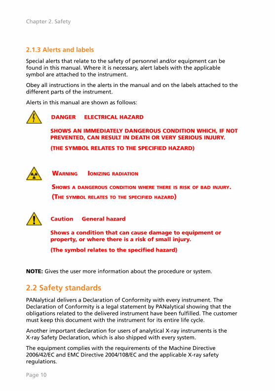
2.1.3 Alerts and labels
Special alerts that relate to the safety of personnel and/or equipment can befound in this manual. Where it is necessary, alert labels with the applicablesymbol are attached to the instrument.
Obey all instructions in the alerts in the manual and on the labels attached to thedifferent parts of the instrument.
Alerts in this manual are shown as follows:
DANGER ELECTRICAL HAZARD
SHOWS AN IMMEDIATELY DANGEROUS CONDITION WHICH, IF NOTPREVENTED, CAN RESULT IN DEATH OR VERY SERIOUS INJURY.
(THE SYMBOL RELATES TO THE SPECIFIED HAZARD)
WARNING IONIZING RADIATION
SHOWS A DANGEROUS CONDITION WHERE THERE IS RISK OF BAD INJURY.(THE SYMBOL RELATES TO THE SPECIFIED HAZARD)
Caution General hazard
Shows a condition that can cause damage to equipment orproperty, or where there is a risk of small injury.
(The symbol relates to the specified hazard)
NOTE: Gives the user more information about the procedure or system.
2.2 Safety standardsPANalytical delivers a Declaration of Conformity with every instrument. TheDeclaration of Conformity is a legal statement by PANalytical showing that theobligations related to the delivered instrument have been fulfilled. The customermust keep this document with the instrument for its entire life cycle.
Another important declaration for users of analytical X-ray instruments is theX‑ray Safety Declaration, which is also shipped with every system.
The equipment complies with the requirements of the Machine Directive2006/42/EC and EMC Directive 2004/108/EC and the applicable X-ray safetyregulations.
Page 10
Chapter 2. Safety

Refer to the applicable standards, normative documents and directives in theDeclaration of Conformity and the X-ray Safety Declaration of the instrument.
2.3 PANalytical's ApproachPANalytical manufactures and supplies analytical X‑ray instruments that fulfill theappropriate international product regulations. This approach results in:
• Specification of the worldwide lowest radiation level: less than 1 µSv/h at10 cm distance from the outside surface of the instrument.
• Risk calculations and assessments with respect to the use of the instrumentshowing that the absorbed dose stays easily within the ICRP (InternationalCommission on Radiological Protection) level for public. This level is 1 mSv/year.
• Overall risk assessment with respect to the safety of the instrument.
• Instrument design, production and documentation certified by notifiedbodies PTB and/or CSA. See the Declaration of Conformity and the X‑raySafety Declaration for detailed information.
• PANalytical's environmental policy deployed across the whole organization.The following measures are taken:
a. Information about environmental aspects of third party products iscollected from the suppliers.
b. Design rules are implemented to reduce energy consumption, packagingmaterials, and weight.
c. Environmental information is supplied together with the instrument inorder to inform service employees and users (people using the system).
• Emission of sound, produced by the instrument during normal operation, incompliance with the requirements of the Machine Directive.
• Instrument design measures to ensure safety with respect to moving parts,such as preventive precautions and warning labels on the instrument and inthe manuals.
Assurance of these processes is achieved by organizational requirements such asISO 9001, ISO 14001, radiation safety board inspections and audits.
2.4 User responsibilitiesIn this section, the responsibilities of the user are listed, which are required tokeep the instrument at the classified safety level.
1. The user must ensure that the instrument is correctly installed. The user’s sitefacilities must meet the specifications in the pre-installation and installation
Page 11
information. Additionally, the facilities must meet the applicable safetyrequirements. Remember that:
a. a suitable ground (earth) must be available.
b. the table must be adequate for the instrument.
2. Installation and maintenance must be carried out by personnel authorized byPANalytical.
3. Safety devices must NEVER be made inoperative.
4. The user must ensure that people using the system are fully instructed in thesafety procedures.
5. The user must ensure that the system is operated according to the locallyapplicable safety regulations.
6. All X‑ray analysis systems must be monitored regularly (based on a local riskassessment) using a suitable radiation monitor.
7. If the instrument is left unattended in an unsafe condition, remove the HT(high-tension) key, disconnect the mains power supply and attach a “DO NOTOPERATE” warning notice to the front panel.
8. When generating X‑rays, the fail-safe warning lamp X‑RAYS ON must be on.This lamp must be clearly visible to everyone in the area.
9. In some countries, a warning lamp must be mounted outside the room, andthe international warning sign must be displayed.
10. After installation or any maintenance/repair procedure, the user and theservice engineer must verify that the safety interlocks function correctly.
11. For troubleshooting, checking the system after repair, or application support,a PANalytical service engineer or application specialist can perform remotesupport on the instrument.
Before starting and performing remote support, the user must take properprecautions to ensure that the instrument can be operated safely withoutlocal intervention.
12. Although the instrument is designed and tested to be safe, maintenance is ofvital importance. Information about user level maintenance is provided inthis guide. Any further maintenance must be performed by the authorizedservice engineer.
2.4.1 What to do in case of an emergency
If an emergency, or a suspected exposure to radiation from an analytical X‑rayinstrument occurs, the following must be done:
1. Switch off the instrument and ensure that it cannot be switched on again.
Page 12
Chapter 2. Safety
2. Take any medical/remedial first aid steps required.
3. Do not take any remedial action to cure the fault that caused the accidentand/or exposure.
NOTE: In the case of an X‑ray exposure incident, assessment of the absorbeddose is more difficult if the fault is corrected.
4. Put a sign on the instrument to indicate that the instrument must not beused or altered in any way.
5. You must notify the following about the occurrence:
• The user
• The (Radiation) Safety officer
• The local PANalytical representative
NOTE: If it is an X‑ray exposure accident and it exceeded the level set inlocal regulations, refer the exposed person for medicalexamination.
2.5 General hazards
2.5.1 Ionizing radiation
Generally, worldwide legislation forbids the use of ionizing radiation. Its use isallowed only when it is justified. This means that it can only be used after specialpermission has been given by the relevant authority.
Protection against ionizing radiation is a safety aspect that is covered in theapplicable standards. The basic principle is to reduce the radiation outside theinstrument to a level that is as low as reasonably achievable (ALARA principle).
When properly operated within the specifications, the radiation level at adistance of 10 cm from the outside surface of the instrument is less than 1 µSv/h.
WARNING IONIZING RADIATION
X-RAYS ARE HARMFUL. THE INSTRUMENT PRODUCES X-RAYS WHICH CAN BEDANGEROUS TO HEALTH IF THE PROPER PRECAUTIONS ARE NOT TAKEN.IT IS IMPORTANT FOR THE HEALTH AND SAFETY OF THE USER THAT THERECOMMENDATIONS GIVEN IN THE INSTRUMENT MANUALS ARE CAREFULLYOBSERVED.LOCAL SAFETY REGULATIONS MUST BE STRICTLY COMPLIED WITH.
Page 13
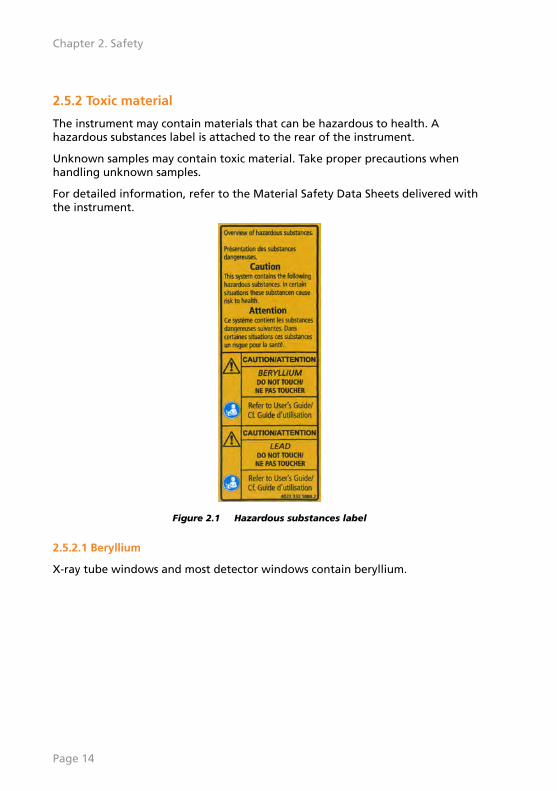
2.5.2 Toxic material
The instrument may contain materials that can be hazardous to health. Ahazardous substances label is attached to the rear of the instrument.
Unknown samples may contain toxic material. Take proper precautions whenhandling unknown samples.
For detailed information, refer to the Material Safety Data Sheets delivered withthe instrument.
Figure 2.1 Hazardous substances label
2.5.2.1 Beryllium
X-ray tube windows and most detector windows contain beryllium.
Page 14
Chapter 2. Safety
WARNING TOXIC MATERIAL
BERYLLIUM AND COMPOUNDS OF BERYLLIUM (FOR EXAMPLE BERYLLIUMOXIDE) ARE POISONOUS.
• DO NOT TOUCH, SWALLOW OR BREATHE IN BERYLLIUM.
• DO NOT GET BERYLLIUM ON YOUR BARE SKIN. ALWAYS WEARGLOVES WHEN YOU TOUCH ITEMS THAT CONTAIN BERYLLIUM.
• IF THERE ARE DUST OR FUMES OF BERYLLIUM, USE A DUST MASKAND PROTECTIVE CLOTHING.
DISPOSAL OF BERYLLIUM MUST OBEY ALL APPLICABLE LOCALREGULATIONS.REFER TO THE SAFETY INFORMATION IN THIS DOCUMENT AND THE RELATEDMATERIAL SAFETY DATA SHEET FOR MORE DETAILS.
2.5.2.2 Lead
Lead is used as a shielding material for X‑rays.
WARNING TOXIC MATERIAL
LEAD AND COMPOUNDS OF LEAD (FOR EXAMPLE LEAD OXIDE) AREPOISONOUS.
• DO NOT TOUCH, SWALLOW OR BREATHE IN LEAD.
• DO NOT GET LEAD ON YOUR BARE SKIN. ALWAYS WEAR GLOVESWHEN YOU TOUCH ITEMS THAT CONTAIN LEAD.
• IF THERE ARE DUST OR FUMES OF LEAD, USE A DUST MASK ANDPROTECTIVE CLOTHING.
DISPOSAL OF LEAD MUST OBEY ALL APPLICABLE LOCAL REGULATIONS.REFER TO THE SAFETY INFORMATION IN THIS DOCUMENT AND THE RELATEDMATERIAL SAFETY DATA SHEET FOR MORE DETAILS.
Page 15

2.5.3 Flammable material
WARNING FLAMMABLE MATERIAL
THE END-USER IS AT ALL TIMES RESPONSIBLE FOR TREATING (THESUBSTANCES OR MATERIALS USED FOR FABRICATING) ITS SAMPLES WITH ALLDUE CARE AND DILIGENCE. PANALYTICAL CANNOT BE HELD LIABLE FORANY DAMAGE RESULTING FROM THE USE OF FLAMMABLE, COMBUSTIBLE OROTHER HAZARDOUS SUBSTANCES OR MATERIALS IN (THE PREPARATION OF)ANY SAMPLES.
2.5.4 Earth leakage current
The leakage current of instruments permanently connected to the mains supplyvoltage may, under some circumstances, exceed 10 mA. Therefore, depending onthe local regulations (based on the risk of a broken earth connection), a secondearth (ground) connection to the instrument may be required.
2.6 Safety measuresThe following sections explain several safety measures and their incorporationinto the instrument.
2.6.1 HT keyswitch
All systems are equipped with an HT keyswitch on the control panel. Theremovable HT key helps the local radiation safety officer to control who uses thesystem.
The HT key must be removed to prevent unauthorized use of the system.However, normal mains power remains available for other functions.
2.6.2 X-RAYS lamps
When the X‑RAYS lamps are on, the instrument is generating X‑rays. TheX‑RAYS lamps are part of the safety circuit. If one of the lamps is defective, nohigh voltage can be generated meaning that no X‑rays can be produced.
Only when the system senses that all conditions are safe will the X‑RAYS lamp goon and high tension be applied to the X‑ray tube. If an X‑RAYS lamp fails, the HTgenerator is switched off and cannot be switched on.
2.6.3 Double independent safety loops
Double independent safety loops are required to ensure fail‑safe operation of theinstrument. It is important to check these loops (vital for X‑ray safety) regularlyand adequately, and to document the results of the checks.
Page 16
Chapter 2. Safety

2.6.4 Xsafe
The user is protected from unexpected exposure to X-rays by the Xsafe safetysystem. This system consists of an electronic board which permanently monitorsvarious switches throughout the instrument to ensure that it is safe for X‑rays tobe generated.
The X‑ray tube in an instrument is powered by a high voltage power supply. Thesafety circuits automatically ensure that the high voltage and X‑rays areimmediately switched off if the instrument becomes unsafe.
To ensure the correct functioning of the Xsafe system, the operation of the safetyswitches must be checked at least once a year. Some safety switches areautomatically tested while the instrument is in use. However, other safetyfeatures may not be used as often as once a year.
NOTE: The Epsilon 4 has no visual indication of the Xsafe status.
2.6.5 Safe use of the instrument
During normal operation of the instrument with all panels in position, there areno safety risks for the operator.
The next sections show possible safety risks from the instrument during samplehandling.
Page 17

2.6.5.1 Alerts and hazards
1 2 1
1. Ionizing radiation: X‑RAYS lamp 2. X-ray beams when energized
Figure 2.2 Front
Page 18
Chapter 2. Safety

1 2 1
1. Ionizing radiation:X‑RAYS lamp
2. Toxic material: system containshazardous substances
Figure 2.3 Rear
Page 19
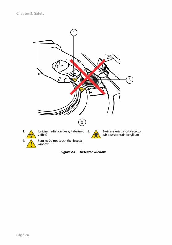
1
2
3
1. Ionizing radiation: X‑ray tube (notvisible)
3. Toxic material: most detectorwindows contain beryllium
2. Fragile: Do not touch the detectorwindow
Figure 2.4 Detector window
Page 20
Chapter 2. Safety
Chapter 3. System description
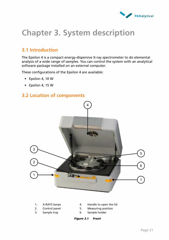
3.1 IntroductionThe Epsilon 4 is a compact energy-dispersive X-ray spectrometer to do elementalanalysis of a wide range of samples. You can control the system with an analyticalsoftware package installed on an external computer.
These configurations of the Epsilon 4 are available:
• Epsilon 4, 10 W
• Epsilon 4, 15 W
3.2 Location of components
3
2
5
6
4
11
1. X-RAYS lamps 4. Handle to open the lid2. Control panel 5. Measuring position3. Sample tray 6. Sample holder
Figure 3.1 Front
Page 21
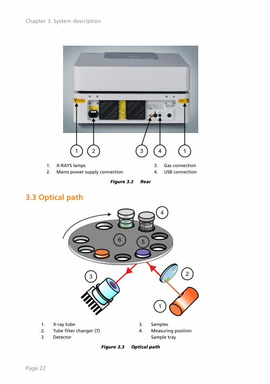
1 12 43
1. X-RAYS lamps 3. Gas connection2. Mains power supply connection 4. USB connection
Figure 3.2 Rear
3.3 Optical path
1
2
4
3
1
2
4
3
1
2
4
3
56
1. X-ray tube 3. Samples2. Tube filter changer (7) 4. Measuring position3 Detector Sample tray
Figure 3.3 Optical path
Page 22
Chapter 3. System description

Chapter 4. Installation
4.1 IntroductionBefore you install the system, make sure that the supplies are installed and agreewith the requirements in the Epsilon 4 Pre-installation manual.
If it is necessary to move the instrument, refer to the Epsilon 4 Pre-installationManual for the requirements about storage, transport and installation.
If you are not sure, always contact your local PANalytical representative.
When the instrument is installed for the first time, a PANalytical service engineermust do the X-ray leakage test. If the instrument is moved, the X-ray leakage testis the responsibility of the customer. We recommend that the X-ray leakage test isdone by a person trained in X-ray safety.
WARNING IONIZING RADIATION
X-RAYS ARE HARMFUL. THE INSTRUMENT PRODUCES X-RAYS WHICH CAN BEDANGEROUS TO HEALTH IF THE PROPER PRECAUTIONS ARE NOT TAKEN.IT IS IMPORTANT FOR THE HEALTH AND SAFETY OF THE USER THAT THERECOMMENDATIONS GIVEN IN THE INSTRUMENT MANUALS ARE CAREFULLYOBSERVED.LOCAL SAFETY REGULATIONS MUST BE STRICTLY COMPLIED WITH.
4.2 Unpack the instrumentNOTE: Keep the original packaging for future transportation.
1. Examine the external impact indicators. Refer to Section 4.2.1.
2. Use a forklift or trolley to move the crate on the pallet as close as possible tothe installation location.
3. Remove the lid of the crate.
4. Remove all sides of the crate.
5. Remove the cardboard box with parts from the pallet.
6. Make sure that all the parts are supplied. Refer to the Packing List in theenvelope. If some parts are missing, contact your local PANalyticalorganization immediately.
7. Open the cardboard box with the instrument.
Page 23

8. Remove the 4 corner buffers.
9. Open the foil.
10. Lift the instrument from the cardboard box. The weight of the Epsilon 4 is~ 47 kg.
WARNING LIFTING HAZARD
THE EPSILON 4 IS HEAVY. IT MUST BE LIFTED BY AT LEAST 2 PERSONS.
Figure 4.1 Lift the instrument with 2 persons
11. Move the instrument to the final installation location with 2 persons. Theinstallation location must have a strong surface, for example, a table.
NOTE: Keep 20 cm space behind the instrument for the airflow and toconnect or disconnect the mains power supply.
Figure 4.2 Installation position
Page 24
Chapter 4. Installation
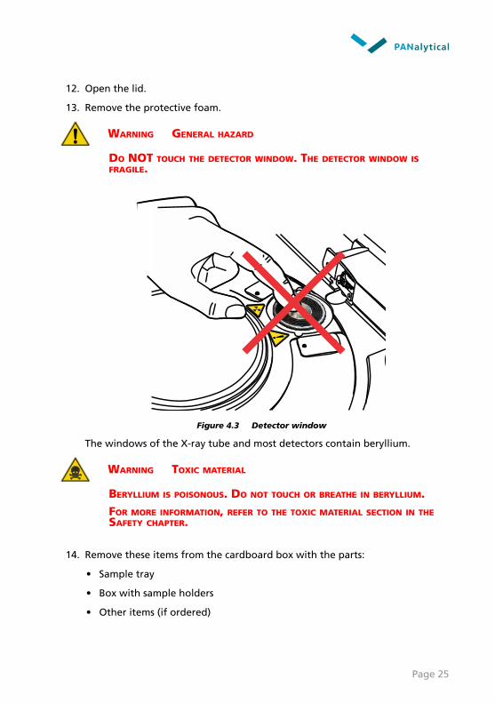
12. Open the lid.
13. Remove the protective foam.
WARNING GENERAL HAZARD
DO NOT TOUCH THE DETECTOR WINDOW. THE DETECTOR WINDOW ISFRAGILE.
Figure 4.3 Detector window
The windows of the X-ray tube and most detectors contain beryllium.
WARNING TOXIC MATERIAL
BERYLLIUM IS POISONOUS. DO NOT TOUCH OR BREATHE IN BERYLLIUM.FOR MORE INFORMATION, REFER TO THE TOXIC MATERIAL SECTION IN THESAFETY CHAPTER.
14. Remove these items from the cardboard box with the parts:
• Sample tray
• Box with sample holders
• Other items (if ordered)
Page 25

4.2.1 Examine the external impact indicators
1. When the instrument is delivered to your site, examine the crates and/orcartons, and any impact indicators that are attached to them.
NOTE: If an impact indicator was attached to a crate or carton beforeshipping, this is shown on the shipping documents.
2. If an impact indicator is activated or missing, or a crate/carton has visibledamage, do as follows.
a. You can accept the shipment, but record the activated or missing indicatorand any visible crate or carton damage on the delivery document.
NOTE: The recorded results of the impact indicator can help with anydamage claims procedure.
b. Contact PANalytical's local organization or agent/representative about thedamaged crate and activated or missing indicator the same day.
3. Store the delivery document for future reference.
4. If you have accepted the shipment, make sure that a customer supportengineer of PANalytical unpacks the instrument and examines it for internaldamage as soon as possible.
4.3 Install the instrument1. Put the sample holders in the sample tray.
Figure 4.4 Put the sample holders in the sample tray
2. Put the sample tray onto the sample changer.
Page 26
Chapter 4. Installation
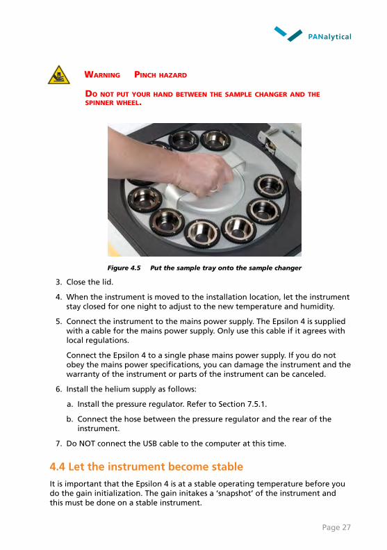
WARNING PINCH HAZARD
DO NOT PUT YOUR HAND BETWEEN THE SAMPLE CHANGER AND THESPINNER WHEEL.
Figure 4.5 Put the sample tray onto the sample changer
3. Close the lid.
4. When the instrument is moved to the installation location, let the instrumentstay closed for one night to adjust to the new temperature and humidity.
5. Connect the instrument to the mains power supply. The Epsilon 4 is suppliedwith a cable for the mains power supply. Only use this cable if it agrees withlocal regulations.
Connect the Epsilon 4 to a single phase mains power supply. If you do notobey the mains power specifications, you can damage the instrument and thewarranty of the instrument or parts of the instrument can be canceled.
6. Install the helium supply as follows:
a. Install the pressure regulator. Refer to Section 7.5.1.
b. Connect the hose between the pressure regulator and the rear of theinstrument.
7. Do NOT connect the USB cable to the computer at this time.
4.4 Let the instrument become stableIt is important that the Epsilon 4 is at a stable operating temperature before youdo the gain initialization. The gain initakes a ‘snapshot’ of the instrument andthis must be done on a stable instrument.
Page 27
1. Close the lid.
2. Press the POWER button to switch on the instrument.
3. Turn the HT keyswitch clockwise to switch on the HT generator.
4. If the instrument is installed for the first time, a PANalytical service engineermust do the X-ray leakage test.
5. Do the X-ray leakage test. Refer to Section 4.4.1.
NOTE: We recommend that the X-ray leakage test is done by a persontrained in X-ray safety.
6. Wait 2 hours until the Epsilon 4 is stable.
4.4.1 Do an X-ray leakage test
In the section PANalytical’s Approach, PANalytical tells that their instrumentsagree with the most strict regulations for ionizing radiation: < 1 µSv/h at adistance of 10 cm from the outside surface of the instrument. Refer to Section 2.3.
An X-ray leakage test is done for each instrument and the X-ray radiation level ismeasured before shipment. Our instruments are intrinsically safe when they areoperated and maintained correctly.
But also if it is not necessary in local regulations, PANalytical recommends thatyou do an X-ray leakage test of the instrument regularly. This is speciallyimportant during the installation, when the instrument is moved or when theinstrument does not get maintenance regularly.
Always use a calibrated X-ray radiation survey meter.
4.5 Install the softwareIf the computer is supplied with the instrument, the software is already installed.If the computer is not supplied with the instrument, you must install the softwareas follows:
1. Put the Epsilon software DVD in the computer. The installation menu startsautomatically.
2. If the installation menu does not show, start SETUP.EXE in the root of theDVD.
3. In the installation menu, click Install Epsilon Controller Software.
NOTE: The Epsilon Controller Software is necessary if the instrument will bedirectly connected to the computer.
4. Do the instructions of the wizard.
5. In the installation menu, click Install Epsilon Software.
Page 28
Chapter 4. Installation

6. Do the instructions of the wizard.
7. When all necessary services are installed, click Exit.
8. Connect the USB cable to the computer. Use the USB cable supplied with thesystem, because it has a ferrite bead layer to prevent EMC interference.
9. Install the USB driver. Refer to Section 4.5.1.
4.5.1 Install the USB driver
1. Examine if MS Windows on the computer is 64-bit or 32-bit as follows:
a. Press the ⊞ Win + Pause/Break key to open the System window.
b. Examine the System type field in the System section to find if you havea 64-bit or a 32-bit operating system.
2. Make sure that you have administrator rights.
3. Open the Device Manager:
a. Press the ⊞ Win + R key to open the Run window.
b. In the Open field, enter “devmgmt.msc”.
c. Click OK.
4. Double-click Epsilon.
5. Select the Driver tab.
6. Click Update Driver.
7. Select Browse my computer for driver software.
8. Go to the Epsilon software disk.
9. Double-click the USB folder (located in Epsilon\Disk1).
10. Double-click the correct folder:
a. If MS Windows on the computer is 64-bit, double-click x64 (64bit).
b. If MS Windows on the computer is 32-bit, double-click x86 (32bit).
11. Click OK.
12. Click Next.
13. Acknowledge the Security warning and the install the driver.
14. Click Close.
Page 29

4.6 Supply connections
87
1
6
100 - 240 Vac ± 10 %50 - 60 Hz
, + PEø
2
3
4 5
1. Mains power supply, with earth (plugtype is related to country)
5. USB cable
2. Power strip 5-way (Euro) 6. Pressure regulator for helium3. USB cable type A (computer) to type B
(instrument), with ferrite bead7. 10 m rubber hose for helium
4. Internet connection 8. Helium cylinder
Figure 4.6 Epsilon 4 supply connections
Page 30
Chapter 4. Installation

Chapter 5. Operate the instrument
5.1 Introduction
Caution General hazard
Before you operate the instrument, obey these instructions:
• The instrument must be safely in position.
• To prevent accidents, the floor around the instrumentmust be dry and there must be no dirt or grease.
5.2 Control panel
9
7
1 2
8
3 4 5 6
1. HT ENABLED indicator 6. mA indicator2. POWER indicator 7. X-rays warning3. LID LOCKED indicator 8. POWER button4. MEASURING indicator 9. HT keyswitch5. kV indicator
Figure 5.1 Control panel
Page 31

5.2.1 POWER button and indicator
When you press the POWER button, the instrument switches to the ON condition.In this condition, all instrument systems except the HT supply are in operation.
The instrument is in the ON condition when the POWER indicator is on.
When you press the POWER button again, the instrument switches to the OFFcondition. In this condition, the HT supply is off but the peripherals are inoperation.
The instrument is in the OFF condition when the POWER indicator is off.
5.2.2 HT keyswitch and HT ENABLED indicator
When you turn the HT keyswitch clockwise, the HT generator goes on. If thesafety loops are closed, the HT generator is automatically set to standby settings.
When the HT generator is in the ON condition, the indicators are as follows:
• The HT ENABLED indicator is on.
• The kV and mA indicators on the control panel show the settings.
• The X-RAYS lamps on the sides of the instrument are on.
When you turn the HT keyswitch counter-clockwise, the HT generator goes off.
The HT keyswitch is also used to reset the Xsafe system. Refer to Section 8.3.1.
If the HT key is removed from the instrument and an unsafe condition is sensed,you cannot switch the high tension on again.
NOTE: The HT key can be removed and kept in a safe place.
5.2.3 LID LOCKED indicator
When the LID LOCKED indicator is off, it is safe to open the lid.
When the sample changer moves or samples are measured, the lid is locked andthe LID LOCKED indicator is on.
5.2.4 MEASURING indicator
During a measurement, the MEASURING indicator is on.
5.3 Switch on the instrument1. Connect the instrument to the mains power supply.
Page 32
Chapter 5. Operate the instrument

2. If a helium gas cylinder is installed, do as follows:
a. Open the main valve of the gas cylinder. The gas cylinder pressure gaugemust show a pressure of approximately 20 MPa.
b. Slowly open the reduction valve until the output pressure gauge shows apressure of 0.08 MPa.
3. Connect the USB cable between the computer and the instrument.
4. Press the POWER button to switch on the instrument.
5. Turn the HT keyswitch clockwise to switch on the HT generator.
6. If the instrument was moved, do the X-ray leakage test. Refer to Section4.4.1.
NOTE: We recommend that the X-ray leakage test is done by a persontrained in X-ray safety.
7. Wait until the temperature is stable.
When you use the instrument for the first time or when the instrument hasbeen switched off for a long period of time, we recommend a warm-up timeof 2 hours.
8. Start the Epsilon software.
5.4 Switch off the instrument1. Close the Epsilon software.
2. Turn the HT keyswitch counter-clockwise to switch off the HT generator.
3. Press the POWER button to switch off the instrument.
4. If a cylinder with helium gas is installed, close the main valve on the cylinder.
5. If it is necessary for the instrument to be switched off for a long period oftime, you can also switch off the mains power supply to the instrument.
5.5 Backup the userdataYou should make regular backups of your userdata to prevent accidental loss orhardware and media failure. Always keep a minimum of one backup off-site in asafe location.
1. Start the Epsilon software.
2. Go to System > Backup userdata to show the Backup userdata window.
3. In the Source field, select the folder "...\panalytical\epsilon\userdata".
Page 33
4. In the Destination field, select a destination folder, for example "...\epsilon-userdata-backup".
NOTE: You only have to specify the source folder and the destination folderthe first time. After that, these are automatically used as default.
5. Click Backup.
Every backup creates a new subfolder in the Destination folder with this format:
YYYYMMDDHHMMSS
where YYYY = year, MM = month, DD = day, HH = hour, MM = minutes,SS = seconds
Page 34
Chapter 5. Operate the instrument

Chapter 6. Measure samples
6.1 Measurement overviewThese steps are necessary to do a measurement:
1. Open the lid.
2. Load one or more samples.
3. If you want to measure “large samples”, first put protection foil on top ofthe measuring position. Refer to Section 6.6.
4. Close the lid.
5. To measure a sample with a measurement program, do as follows:
a. Start the Epsilon software.
b. Create an application.
c. Go to Measure > Measure application.
d. Select the application.
e. Click Measure to start the measurement.
f. Select the position on the sample changer. The sample automaticallymoves to the measuring position and the measurement is done as given inthe analytical software.
6. To measure a sample manually, do as follows:
a. Start the Epsilon software.
b. Go to Measure > Manual control.
c. In the Sample changer field, enter the position of the sample.
d. Click Move.
e. The sample automatically moves to the measuring position and themeasurement is done as given in the analytical software.
The On-line status window opens during a measurement. It shows thestatus of the measurement and the temporary results.
Page 35
6.2 Sample typesYou can measure these sample types with the Epsilon 4:
• Solid samples.
These samples must be between 27 and 51.5 mm diameter with a maximumheight of 10 cm.
• Liquid samples.
These samples are usually 10 ml. They must be put in the special ‘P1 liquidcell’. The liquid cells must be put in steel sample holders.
6.3 Sample loadingYou must load samples manually or with a robot arm when you have aninstrument with automation kit.
WARNING TOXIC MATERIAL
IF YOU MEASURE UNKNOWN OR TOXIC SAMPLES, REFER TO THE MATERIALSAFETY DATA SHEET ABOUT HANDLING INSTRUCTIONS.
WARNING FLAMMABLE MATERIAL
THE USER IS ALWAYS RESPONSIBLE TO USE ITS SAMPLES, AND ITSMATERIALS TO PREPARE THESE SAMPLES, VERY CAREFULLY AND CORRECTLY.PANALYTICAL IS NOT LEGALLY RESPONSIBLE FOR DAMAGE THAT IS CAUSEDBY FLAMMABLE SAMPLES, OR BY OTHER HAZARDOUS MATERIALS IN THESAMPLES OR THAT ARE USED WHEN THE SAMPLES ARE PREPARED.
Page 36
Chapter 6. Measure samples

Caution General hazard
To prevent contamination of the measurement chamber andoptical path, obey these instructions:
• Only use sample cups that are approved for use inPANalytical instruments.
• For liquid cups, make sure that the cup lid is safely inposition.
• Do not keep temperature sensitive samples in theinstrument for a long period.
If a pressed powder sample breaks or a liquid sample leaks inthe measurement chamber or the optical path, immediatelyswitch off the instrument. Do not clean the contaminated parts.A PANalytical service engineer must clean the measurementchamber and the optical path.
6.4 Sample tray
Figure 6.1 Sample tray layout
NOTE: The sample positions are on the sample tray.
6.5 Load samples1. Open the lid.
2. Put the sample holders on the sample tray.
Page 37

3. Put the sample tray with sample holders onto the sample changer.
WARNING PINCH HAZARD
DO NOT PUT YOUR HAND BETWEEN THE SAMPLE CHANGER AND THESPINNER WHEEL.
Figure 6.2 Put the sample tray onto the sample changer
4. Put the sample in a sample cup of the correct size.
5. Put the sample cup in a sample holder on the sample tray.
6. Do steps 4 and 5 again for all samples that you want to measure.
Figure 6.3 Put sample cups in the sample holders
7. Close the lid.
Page 38
Chapter 6. Measure samples

6.6 Measure large samplesWhen you want to measure large samples, you must protect the measuringposition with a protection foil.
NOTE: Only use the protection foil on top of the measuring position when youmeasure in Large Sample mode.
1. Start the Epsilon software.
2. Go to System > Enter “Large Sample” mode. The beam stopautomatically moves away from the measuring position.
3. Do the instructions on the screen.
WARNING GENERAL HAZARD
DO NOT TOUCH THE DETECTOR WINDOW. THE DETECTOR WINDOW ISFRAGILE.
Figure 6.4 Detector window
The windows of the X-ray tubes and most detectors are made of beryllium.
Page 39
WARNING TOXIC MATERIAL
BERYLLIUM IS POISONOUS. DO NOT TOUCH OR BREATHE IN BERYLLIUM.FOR MORE INFORMATION, REFER TO THE TOXIC MATERIAL SECTION IN THESAFETY CHAPTER.
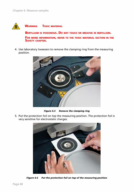
4. Use laboratory tweezers to remove the clamping ring from the measuring
position.
Figure 6.5 Remove the clamping ring
5. Put the protection foil on top the measuring position. The protection foil isvery sensitive for electrostatic charges.
Figure 6.6 Put the protection foil on top of the measuring position
Page 40
Chapter 6. Measure samples

6. Put the clamping ring around the measuring position.
7. Carefully push the clamping ring down.
8. Remove the paper frame.
Figure 6.7 Remove the paper frame
9. Use the laboratory tweezers to put small holes in the protection foil, on topof the four holes of the measuring position.
NOTE: The holes are necessary to release helium gas and air duringmeasurements.
Figure 6.8 Put small holes in the protection foil
10. Put the sample on top of the protection foil.
11. Close the lid.
Page 41
12. Turn the HT keyswitch clockwise to switch on the HT generator.
13. Start the measurement.
14. Wait until the measurement is completed.
15. Make sure that the HT is in the standby settings.
16. Turn the HT keyswitch counter-clockwise to switch off the HT generator.
17. Open the lid.
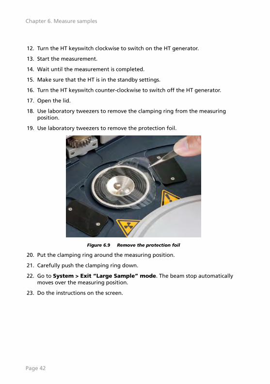
18. Use laboratory tweezers to remove the clamping ring from the measuringposition.
19. Use laboratory tweezers to remove the protection foil.
Figure 6.9 Remove the protection foil
20. Put the clamping ring around the measuring position.
21. Carefully push the clamping ring down.
22. Go to System > Exit “Large Sample” mode. The beam stop automaticallymoves over the measuring position.
23. Do the instructions on the screen.
Page 42
Chapter 6. Measure samples
Chapter 7. User maintenance
7.1 IntroductionFollow the safety precautions of this User's Guide when you do any of theseprocedures. Refer to Chapter 2.
WARNING GENERAL HAZARD
IF THE SYSTEM IS IN AN UNSAFE CONDITION AND YOU GO TO A DIFFERENTROOM, DO AS FOLLOWS:
• DISCONNECT THE SYSTEM FROM THE MAINS POWER SUPPLY.
• PUT A WARNING NOTICE ON THE INSTRUMENT.
• REMOVE THE HT KEY.
To do these procedures, it can be necessary to move the instrument from itsnormal operating position.
Table 7.1 Maintenance schedule
Maintenance procedure Maintenance interval Reference
Test of the safety integrity Every year Refer to Section 7.2.
Clean the instrument When necessary Refer to Section 7.3.
Clean the dust filters of the air inlet When necessary Refer to Section 7.4.
Replace the gas cylinder When necessary Refer to Section 7.5.1.
7.2 Test of the safety integrityThis test is necessary to make sure that the HT keyswitch, Xsafe and safety loopswork correctly and to move the related switches.
1. Press the POWER button to switch on the instrument.
2. Wait until the initialization is finished.
3. Turn the HT keyswitch clockwise to switch on the HT generator.
4. Make sure that the X-RAYS lamps go on.
5. Turn the HT keyswitch counter-clockwise to switch off the HT generator.
6. Make sure that the X-RAYS lamps go off.
7. After 5 seconds, turn the HT keyswitch clockwise.
8. Start the Epsilon software.
Page 43
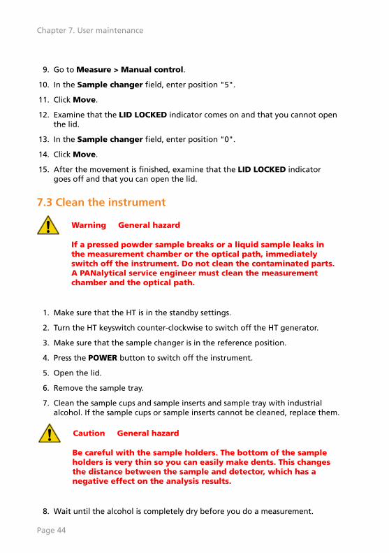
9. Go to Measure > Manual control.
10. In the Sample changer field, enter position "5".
11. Click Move.
12. Examine that the LID LOCKED indicator comes on and that you cannot openthe lid.
13. In the Sample changer field, enter position "0".
14. Click Move.
15. After the movement is finished, examine that the LID LOCKED indicatorgoes off and that you can open the lid.
7.3 Clean the instrument
Warning General hazard
If a pressed powder sample breaks or a liquid sample leaks inthe measurement chamber or the optical path, immediatelyswitch off the instrument. Do not clean the contaminated parts.A PANalytical service engineer must clean the measurementchamber and the optical path.
1. Make sure that the HT is in the standby settings.
2. Turn the HT keyswitch counter-clockwise to switch off the HT generator.
3. Make sure that the sample changer is in the reference position.
4. Press the POWER button to switch off the instrument.
5. Open the lid.
6. Remove the sample tray.
7. Clean the sample cups and sample inserts and sample tray with industrialalcohol. If the sample cups or sample inserts cannot be cleaned, replace them.
Caution General hazard
Be careful with the sample holders. The bottom of the sampleholders is very thin so you can easily make dents. This changesthe distance between the sample and detector, which has anegative effect on the analysis results.
8. Wait until the alcohol is completely dry before you do a measurement.
Page 44
Chapter 7. User maintenance

9. Disconnect all cables at the rear of the instrument.
10. Make sure that there is no damage or leakage at the rear of the instrument.
11. Clean the outer side of the instrument with a moist cloth.
12. Clean the inner side of the instrument with a lint-free cloth. Do not clean theoptical path.
Figure 7.1 Clean the inner side
13. Put the sample tray onto the sample changer.
14. Close the lid.
15. Connect all cables at the rear of the instrument.
16. Press the POWER button to switch on the instrument.
17. If helium is installed, make sure that it operates correctly.
18. Turn the HT keyswitch clockwise to switch on the HT generator.
7.4 Clean the dust filters of the air inlet
CAUTION GENERAL HAZARD
Replace the dust filters of the air inlets regularly. If there is duston the air inlets, the fans cannot decrease the temperature ofthe components and the electrical circuits can become damaged.
1. Remove the two black covers with dust filters from the rear of the
instrument.
Page 45
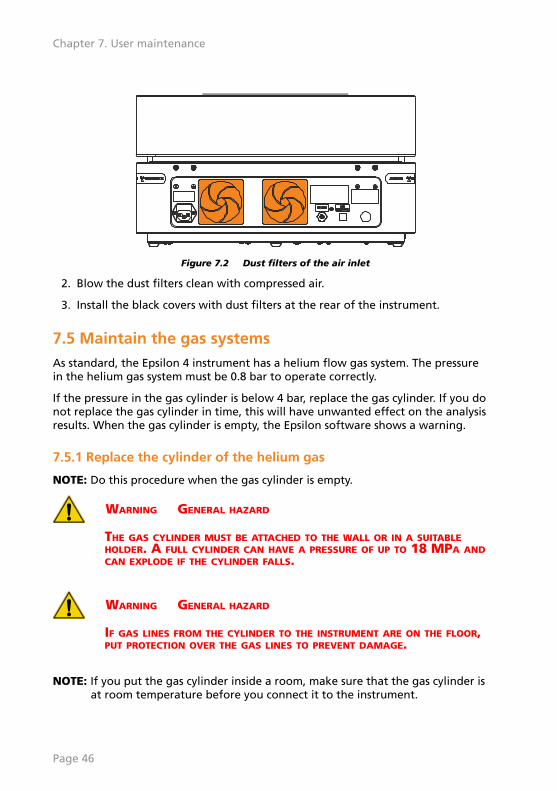
Figure 7.2 Dust filters of the air inlet
2. Blow the dust filters clean with compressed air.
3. Install the black covers with dust filters at the rear of the instrument.
7.5 Maintain the gas systemsAs standard, the Epsilon 4 instrument has a helium flow gas system. The pressurein the helium gas system must be 0.8 bar to operate correctly.
If the pressure in the gas cylinder is below 4 bar, replace the gas cylinder. If you donot replace the gas cylinder in time, this will have unwanted effect on the analysisresults. When the gas cylinder is empty, the Epsilon software shows a warning.
7.5.1 Replace the cylinder of the helium gas
NOTE: Do this procedure when the gas cylinder is empty.
WARNING GENERAL HAZARD
THE GAS CYLINDER MUST BE ATTACHED TO THE WALL OR IN A SUITABLEHOLDER. A FULL CYLINDER CAN HAVE A PRESSURE OF UP TO 18 MPA ANDCAN EXPLODE IF THE CYLINDER FALLS.
WARNING GENERAL HAZARD
IF GAS LINES FROM THE CYLINDER TO THE INSTRUMENT ARE ON THE FLOOR,PUT PROTECTION OVER THE GAS LINES TO PREVENT DAMAGE.
NOTE: If you put the gas cylinder inside a room, make sure that the gas cylinder isat room temperature before you connect it to the instrument.
Page 46
Chapter 7. User maintenance
4
5
2 1
6 7
3
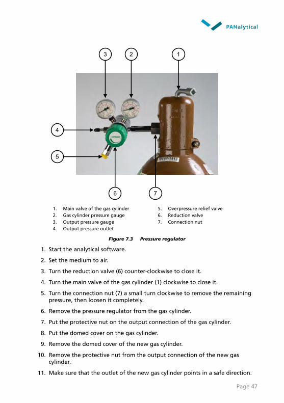
1. Main valve of the gas cylinder 5. Overpressure relief valve2. Gas cylinder pressure gauge 6. Reduction valve3. Output pressure gauge 7. Connection nut4. Output pressure outlet
Figure 7.3 Pressure regulator
1. Start the analytical software.
2. Set the medium to air.
3. Turn the reduction valve (6) counter-clockwise to close it.
4. Turn the main valve of the gas cylinder (1) clockwise to close it.
5. Turn the connection nut (7) a small turn clockwise to remove the remainingpressure, then loosen it completely.
6. Remove the pressure regulator from the gas cylinder.
7. Put the protective nut on the output connection of the gas cylinder.
8. Put the domed cover on the gas cylinder.
9. Remove the domed cover of the new gas cylinder.
10. Remove the protective nut from the output connection of the new gascylinder.
11. Make sure that the outlet of the new gas cylinder points in a safe direction.
Page 47
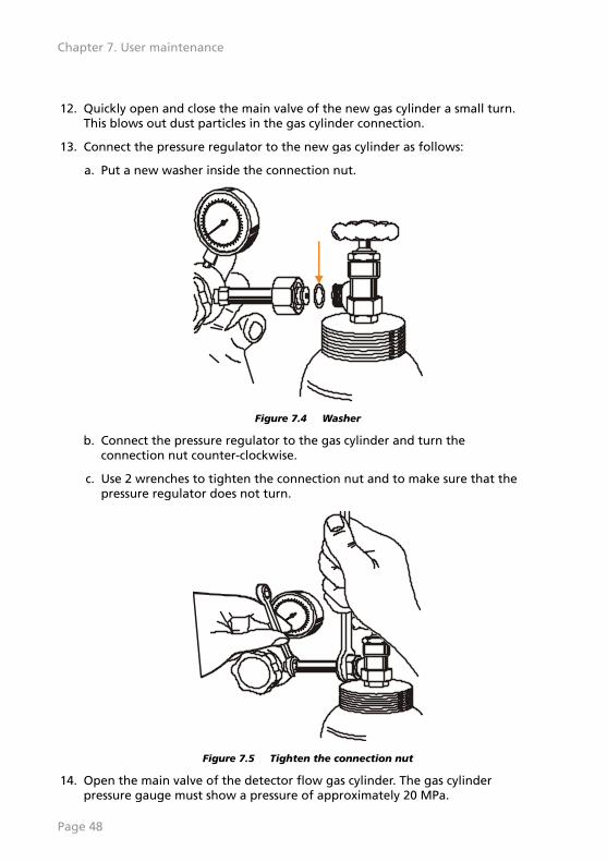
12. Quickly open and close the main valve of the new gas cylinder a small turn.This blows out dust particles in the gas cylinder connection.
13. Connect the pressure regulator to the new gas cylinder as follows:
a. Put a new washer inside the connection nut.
Figure 7.4 Washer
b. Connect the pressure regulator to the gas cylinder and turn theconnection nut counter-clockwise.
c. Use 2 wrenches to tighten the connection nut and to make sure that thepressure regulator does not turn.
Figure 7.5 Tighten the connection nut
14. Open the main valve of the detector flow gas cylinder. The gas cylinderpressure gauge must show a pressure of approximately 20 MPa.
Page 48
Chapter 7. User maintenance

15. Do a leakage test of the gas system. Refer to Section 7.5.2.
If there is no leak, continue with the next step.
16. Slowly open the reduction valve of the detector flow gas cylinder until theoutput pressure gauge (4) shows a pressure of 0.08 MPa.
17. Set the medium to helium.
7.5.2 Leakage test of the gas system
Do a leakage test of the gas system each time a gas cylinder is connected to theinstrument.
1. Close the main valve of the gas cylinder.
2. Close the reduction valve.
3. Slowly open the main valve of the gas cylinder.
4. Write down the pressure value.
5. Close the main valve of the gas cylinder.
6. Keep the main valve of the gas cylinder closed for approximately 30 minutes.
7. After approximately 30 minutes, compare the pressure value with thepressure value of step 4.
If the pressure value is the same, there is no leak.
If the pressure has decreased, there is a leak in the connection between thegas cylinder and the pressure regulator. Repair the leak.
7.5.2.1 Repair a leak in the gas system
1. Turn the reduction valve (6) counter-clockwise to close it.
2. Turn the main valve of the gas cylinder (1) clockwise to close it.
3. Turn the connection nut (7) a small turn clockwise to remove the remainingpressure, then loosen it completely.
4. Remove the pressure regulator from the gas cylinder.
5. Use petroleum ether to carefully clean the coupling.
6. Connect the pressure regulator to the gas cylinder and turn the connectionnut counter-clockwise.
7. Open the main valve of the gas cylinder.
8. Do a leakage test of the gas system again.
Page 49

7.6 Consumable materialsTable 7.2 Consumable materials for maintenance
Item Ordering code
Protection foil for optical path 9430 500 07101
Dust filter (1) 5322 784 02871
Dust filters (set of 25) 5322 784 04251
Sample tray bearing ring 5332 000 03291
Page 50
Chapter 7. User maintenance

Chapter 8. Troubleshooting
8.1 IntroductionThis chapter gives the most common problems with the system and theirsolutions.
If a problem is not in this chapter, or if the solution did not remove it, collect allrelevant information about the problem and contact your local PANalyticalservice organization.
If possible, a PANalytical service engineer uses remote support to find a solutionfor the problem. During a remote support session, your aid can be necessary. If aremote support session did not remove the problem, a service visit can benecessary.
8.2 Instrument does not switch onTable 8.1 Possible causes for instrument does not switch on
Cause Solution Reference
The instrument is not switched on. Switch on the instrument. Refer to Section 5.3.
A fuse has blown in the mains powersupply.
Replace the fuse. Refer to Section 8.2.1.
8.2.1 Replace the mains power fuses
There are two 5 A, 250 V slow-blow mains fuses above the mains power supplysocket of the instrument. These fuses must only be replaced by AuthorizedPersonnel.
1. Disconnect the instrument from the mains power supply.
2. Use a flat screwdriver to pull the fuse holder out off the socket.
3. Remove the fuses from the fuse holder.
4. Put the new fuses in the fuse holder.
5. Push the fuse holder back into the socket.
6. Connect the instrument to the mains power supply.
7. If the fuses blow again, do as follows:
a. Disconnect the instrument from the mains power supply.
b. Contact your local PANalytical service organization.
Page 51
8.3 HT generator does not switch onIf the HT generator does not switch on, there is usually a problem in the HT safetycircuit.
Table 8.2 Possible causes for HT generator does not switch on
Cause Solution Reference
HT keyswitch is in the OFF position. Turn the HT keyswitchclockwise.
Refer to Section 5.2.2.
1 or more of the X-RAYS lamps on thecorners of the instrument is defective.
Contact your localPANalytical serviceorganization.
Xsafe is activated. Reset Xsafe. Refer to Section 8.3.1.
8.3.1 Reset Xsafe
NOTE: The Epsilon 4 has no visual indication of the Xsafe status.
When you think that the Xsafe system is activated, do as follows:
1. Turn the HT keyswitch counter-clockwise to switch off the HT generator.
2. Turn the HT keyswitch clockwise to switch on the HT generator.
3. Switch on the instrument. Refer to Section 5.3.
Page 52
Chapter 8. Troubleshooting

Chapter 9. Disposal instructions
9.1 WEEE directiveThe instrument complies with the WEEE Directive (Waste of Electrical andElectronic Equipment), identified by this alert symbol on the instrument:
Figure 9.1 WEEE directive alert symbol
The function of the European WEEE Directive is to decrease the quantity of wastefrom electrical and electronic equipment, and to decrease the hazardoussubstances of this waste to protect human health and the environment.
9.2 Hazardous substancesWhen you dispose of hazardous materials, obey all applicable and localregulations to prevent damage to the environment. You can also send thehazardous materials back to PANalytical for disposal. Use a recorded shippingmethod.
On the instrument, the hazardous materials are identified with a label.
If you are not sure about the correct disposal procedure, contact your localPANalytical representative.
9.2.1 Beryllium
The windows of X-ray tubes and most detectors contain beryllium (Be).
WARNING TOXIC MATERIAL
BERYLLIUM IS POISONOUS. DO NOT TOUCH OR BREATHE IN BERYLLIUM.FOR MORE INFORMATION, REFER TO THE TOXIC MATERIAL SECTION IN THESAFETY CHAPTER.
9.2.2 Lead
The base plate and the beam stop contain lead (Pb).
Page 53
WARNING TOXIC MATERIAL
LEAD IS POISONOUS. DO NOT TOUCH OR BREATHE IN L.FOR MORE INFORMATION, REFER TO THE TOXIC MATERIAL SECTION IN THESAFETY CHAPTER.
9.2.3 X-ray tube
The window of the C-Tech X-ray tube contains beryllium (Be).
For disposal instructions, refer to the Tube Instruction Manual supplied with theX-ray tube.
9.2.4 Detector
The window of the silicon drift detector contains beryllium (Be).
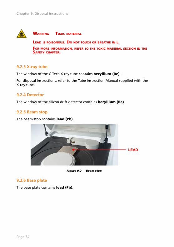
9.2.5 Beam stop
The beam stop contains lead (Pb).
LEAD
Figure 9.2 Beam stop
9.2.6 Base plate
The base plate contains lead (Pb).
Page 54
Chapter 9. Disposal instructions

LEAD
Figure 9.3 Base plate
Page 55

Page 56
Chapter 9. Disposal instructions

IndexA
Alerts and hazards. . . . . . . 18Alerts and labels. . . . . . . . 10Authorized personnel. . . . . 9
BBackup userdata. . . . . . . . 33Beryllium. . . . . . . . . . . 53, 14
Detector. . . . . . . . . . . . . 54X-ray tube. . . . . . . . . . . 54
CClean. . . . . . . . . . . . . . . . . . . .
Dust filter. . . . . . . . . . . . 45Instrument. . . . . . . . . . . 44
Components. . . . . . . . . . . . 21Optical path. . . . . . . . . . 22
Consumable materials. . . . 50Control panel. . . . . . . . . . . 31
DDisposal. . . . . . . . . . . . . . . 53
Base plate. . . . . . . . . . . 54Beam stop. . . . . . . . . . . 54Beryllium. . . . . . . . . . . . 53Detector. . . . . . . . . . . . . 54Lead. . . . . . . . . . . . . . . . 53WEEE directive. . . . . . . . 53X-ray tube. . . . . . . . . . . 54
Double independent safetyloops. . . . . . . . . . . . . . . . . . 16Dust filter. . . . . . . . . . . . . . 45
EEmergency. . . . . . . . . . . . . 12External impact indicators. 26
GGas systems. . . . . . . . . . . . . 46
Gas cylinder. . . . . . . . . . 49Replace gas cylinder. . . 46Leakage test. . . . . . . . . 49Maintenance. . . . . . . . . 46Pressure regulator. . . . . 47
HHazard. . . . . . . . . . . . . . . . 13
Earth leakage current. . 16Flammable material. . . 16Ionizing radiation. . . . . 13Toxic material. . . . . . . . 14Beryllium. . . . . . . . . . . . 14Lead. . . . . . . . . . . . . . . . 15
Hazardous substances. 53, 14HT ENABLED indicator. . . . 32HT generator. . . . . . . . . . . . . .
Does not switch on. . . . 52HT keyswitch. . . . . . . . 16, 32
IInstallation. . . . . . . . . . . . . 23
External impact indicators. . . . . . . . . . . . . . . . . . . . . 26Software. . . . . . . . . . . . 28USB driver. . . . . . . . . . . 29Unpack. . . . . . . . . . . . . . 23X-ray leakage test. . . . . 28
Instrument does not switchon. . . . . . . . . . . . . . . . . . . . 51
LLarge samples. . . . . . . . . . . 39Lead. . . . . . . . . . . . . . . 53, 15LID LOCKED indicator. . . . 32
MMains power fuses. . . . . . . 51Maintenance schedule. . . . 43Measurement overview. . . 35
Large samples. . . . . . . . 39MEASURING indicator. . . . 32
OOptical path. . . . . . . . . . . . 22
PPOWER button. . . . . . . . . . 32POWER indicator. . . . . . . . 32Pressure regulator. . . . . . . 47
RReplace. . . . . . . . . . . . . . . . . .
Replace gas cylinder. . . 46Mains power fuses. . . . . 51
Page 57
Reset. . . . . . . . . . . . . . . . . . . . Xsafe. . . . . . . . . . . . . . . 52
SSafety aspects. . . . . . . . . . . . 9Safety guarantee. . . . . . . . . 9Safety integrity test. . . . . . 43Safety measures. . . . . . . . . 16Safety standards. . . . . . . . . 10Sample loading. . . . . . . . . 36Sample tray. . . . . . . . . . . . 37Sample types. . . . . . . . . . . 36Skill levels. . . . . . . . . . . . . . . 7
Application engineer. . . 8Operator. . . . . . . . . . . . . 7System engineer. . . . . . . 8
Switch off instrument. . . . 33Switch on instrument. . . . 32
UUser responsibilities. . . . . . 11
WWEEE directive. . . . . . . . . . 53
XX-ray leakage test. . . . . . . 28X-RAYS lamps. . . . . . . . . . . 16Xsafe. . . . . . . . . . . . . . . 52, 17
Page 58
Index