Embed Size (px)
Citation preview

4× 4multiple-input multiple-output coherent microwavephotonic link with optical independent sideband and
optical orthogonal modulation(Invited Paper)
Xiang Chen and Jianping Yao*
Microwave Photonics Research Laboratory, School of Electrical Engineering and Computer Science,University of Ottawa, Ottawa, Ontario K1N 6N5, Canada
*Corresponding author: [email protected] October 14, 2016; accepted December 15, 2016; posted online January 9, 2017
A 4 × 4 multiple-input multiple-output coherent microwave photonic (MWP) link to transmit four wirelesssignals with an identical microwave center frequency over a single optical wavelength based on optical indepen-dent sideband (OISB) modulation and optical orthogonal modulation with an improved spectral efficiency isproposed and experimentally demonstrated. At the transmitter, the OISB modulation and optical orthogonalmodulation are implemented to generate an OISB signal using a dual-parallel Mach–Zehnder modulator (DP-MZM) driven by four microwave orthogonal frequency-division multiplexing (OFDM) signals with an identicalmicrowave center frequency. At the receiver, the OISB signal is coherently detected at a coherent receiver where afree-running local oscillator (LO) laser source is employed.Digital signal processing is then used to recover the fourOFDMsignals, to eliminate the phase noise from the transmitter laser source and theLO laser source, and to cancelthe unstable wavelength difference between the wavelengths of the transmitter laser source and the LO lasersource. Error-free transmission of three 16 quadrature amplitude modulation (16-QAM) 1 Gbps OFDM signalsand one 16-QAM 1.5 Gbps OFDM signal at a microwave center frequency of 2.91 GHz over a 10 km single-modefiber is experimentally demonstrated.
OCIS codes: 060.0060, 060.5625, 060.2840.doi: 10.3788/COL201715.010008.
The transmission of microwave signals over an opticalfiber, or a microwave photonic (MWP) link, has been con-sidered as a simple, low cost, and low-power-consumptionsolution for broadband wireless signal transmission[1,2].Such links also enable a centralized radio access network(C-RAN) architecture, which can reduce the network com-plexity and system cost, offering improved network perfor-mance via coordinated multipoints and improved networkenergy efficiency[3]. In addition, in a C-RAN the central sta-tions (CSs) are located in physically secured locations, thusinternet protocol security for the links between theCSs andthe core network is no longer needed. On the other hand, tomeet the requirement of a huge amount of mobile and wire-less local area network data and enable multiple-inputmultiple-output (MIMO)—a key technology for thefifth-generation (5G), MWP links are required to transmitmultiple wireless signals over a single fiber. One solution isto transmit digitized in-phase (I) and quadrature (Q) com-ponents ofmultiple wireless signals in a binary sequence viatime-division multiplexing (TDM), which is widely used intoday’s mobile fronthaul[3–5]. Although such a techniquecan offer excellent robustness against noise, the spectral ef-ficiency is very low since ON-OFF-keying (OOK) modula-tion format is employed[5]. In addition, the use of TDMinherently limits the performance in terms of the latencyof the system. To improve the bandwidth efficiency anddecrease the latency, the transmission of multiple wireless
signals via frequency-divisionmultiplexing (FDM) in a sin-gle wavelength has been proposed[6–8]. The main disadvant-age of the two solutions[3–8] is that at the remote radio head(RRH) electrical local oscillators (ELOs) with differentfrequencies for different wireless signals used to realize fre-quency conversion are required, making the RRH verycostly. To avoid using ELOs at the RRH several schemeshave been proposed[9,10]. In Ref. [9], a simple 2 × 2 MIMOorthogonal frequency division multiplex (OFDM) MWPlink employing single-sideband modulation was proposedthat can tolerate the chromatic dispersion existing in thefiber link. To cancel the high peak-to-average-power ratiodue to theOFDMmodulation[9], single-sideband single-car-rier modulation, which has a lower peak-to-average-powerratio, was employed[10]. For both schemes, to realize a 2 × 2MIMO MWP link, multiple optical wavelengths to carrydifferent wireless signals have to be employed[9,10]. Thus,multiple optical wavelengths, multiple modulators, andmultiple photodiodes (PDs) have to be used, which wouldmake the system complicated and costly. In addition, thespectral efficiency for each channel (each wavelength) isvery low. To simplify the system, increase the spectral ef-ficiency, and avoid using ELOs at the RRH, several MIMOoptical-wireless integration systems have been proposedin which optical polarization multiplexing has to beemployed. For example, a 2 × 2 MIMO MWP link imple-mented using two orthogonally polarized optical light
COL 15(1), 010008(2017) CHINESE OPTICS LETTERS January 10, 2017
1671-7694/2017/010008(7) 010008-1 © 2017 Chinese Optics Letters

waves to carry two microwave signals was reported[11–13].Recently, we proposed two schemes to transmit two inde-pendent microwave vector signals with an identical micro-wave center frequency in a single wavelength basedon coherent detection for a 2 × 2 MIMO MWP link[14,15].However, there are several disadvantages for the twoschemes in Refs. [14,15]. First, in Ref. [14], the phase noiseintroduced by the transmitter laser source was not can-celled, which may degrade the transmission performance.Second, in Refs. [14,15], an unmodulated optical carrierthat has a polarization state orthogonal to the modulatedoptical signal is transmitted to the receiver side for coherentdetection. Since the two orthogonal polarization states areused, polarization multiplexing cannot be implemented,whichwould reduce the transmission capacity anddecreasethe optical energy efficiency. In addition, in Ref. [14], sincethe unmodulated optical carrier from the transmitter isused as an optical local oscillator (LO) for coherent detec-tion, it has to be amplified at the receiver by an optical am-plifier to satisfy the power level needed for coherentdetection, which may add an additional noise to the link.In this Letter, anMWP link to transmit four wireless sig-
nals with an identical microwave center frequency withoutusing FDM over a single optical wavelength based on op-tical independent sideband (OISB)modulation and opticalorthogonal modulation incorporating optical coherent de-tection and digital signal processing (DSP) is proposed andexperimentally demonstrated. In the proposed scheme,four independent microwave signals are transmitted tothe receiver, which enables 4 × 4 MIMO and no ELOsare neededat theRRH for frequency conversion.Comparedwith the schemes in Refs. [3–8], due to the use of OISBmodulation, optical orthogonal modulation and coherentdetection that can detect both the phase and intensity in-formation of optical signals are employed, the spectral ef-ficiency and the number of transmitted wireless signals foreach channel (or wavelength) is increased. In addition, theLO is not from the transmitter, no optical amplifier isneeded, and no additional noise from the optical amplifierwill be introduced. Furthermore, since the remote LO is re-placed by an LO at the receiver side, polarization multi-plexing can be employed that would enable 8 × 8MIMO. In addition, since the four microwave signals arewith an identical microwave center frequency, more micro-wave signals using FDM could be transmitted, thus thedata rate could be further increased. Finally, the phasenoise and unstable frequency difference introduced bythe transmitter laser source and the LO laser source arecancelled by a DSP-based phase noise cancellation unit.A proof-of-concept experiment is performed. Three 1 GbpsOFDM signals and a 1.5 Gbps OFDM signal all with 16quadrature amplitude modulation (16-QAM) at an identi-cal microwave carrier frequency of 2.91 GHz modulated ona single optical carrier are transmitted over a 10 km single-mode fiber (SMF).When the received optical power is only−20.3 dBm, the raw bit error rates (BERs) of the fourwireless signals are still less than 3 × 10⁻³, which enables
error-free transmission if the state-of-the-art forward errorcorrection (FEC) technique is employed.
Figure 1 shows the schematic of the proposed coherentMWP link based onOISBmodulation and optical orthogo-nal modulation. A continuous-wave (CW) light from alaser diode (LD) is sent to a dual-parallel Mach–Zehndermodulator (DP-MZM), which consists of three MZMs(two sub-MZMs, sub-MZM1and sub-MZM2, and onemainMZM). The main MZM is biased at the quadrature pointand the sub-MZM2 is biased at the null point while sub-MZM1 is low biased. Two microwave signals are appliedto theDP-MZMvia the two electrodes.At the output of theDP-MZM, two optical pilot tones, an optical carrier and anOISB signal that contains four microwave OFDM signals,are generated. Each sideband carries two OFDM signalswhose optical subcarriers are orthogonal. After a 10 kmSMF transmission, the OISB signal is coherently detectedat the receiver. After DSP, the four microwave OFDM sig-nals are separated and the phase noise and unstable fre-quency difference between the transmitter laser sourceand the LO laser source are cancelled. In the signal process-ing unit, no ELOs are needed.
Figure 2 shows the principle of the dual independentsideband generation with four real OFDM signals. First,four baseband real OFDM signals, which are individuallyvector mapped, are generated. Note, the modulation for-mat, the symbol rate, the bandwidth, and the number ofsubcarriers of each real OFDM signal can be different. Sec-ond, the four baseband OFDM signals S1ðtÞ, S2ðtÞ, S3ðtÞ,and S4ðtÞ, modulate the RF carriers in a complex sinusoi-dal form. S1ðtÞ is carried by the positive frequency carrierin the form of expðjωRFtÞ, S2ðtÞ is carried by the carrier
Fig. 1. Schematic diagram of the proposed coherent MWP linkbased on OISB modulation and optical orthogonal modulation.PC: polarization controller.
COL 15(1), 010008(2017) CHINESE OPTICS LETTERS January 10, 2017
010008-2
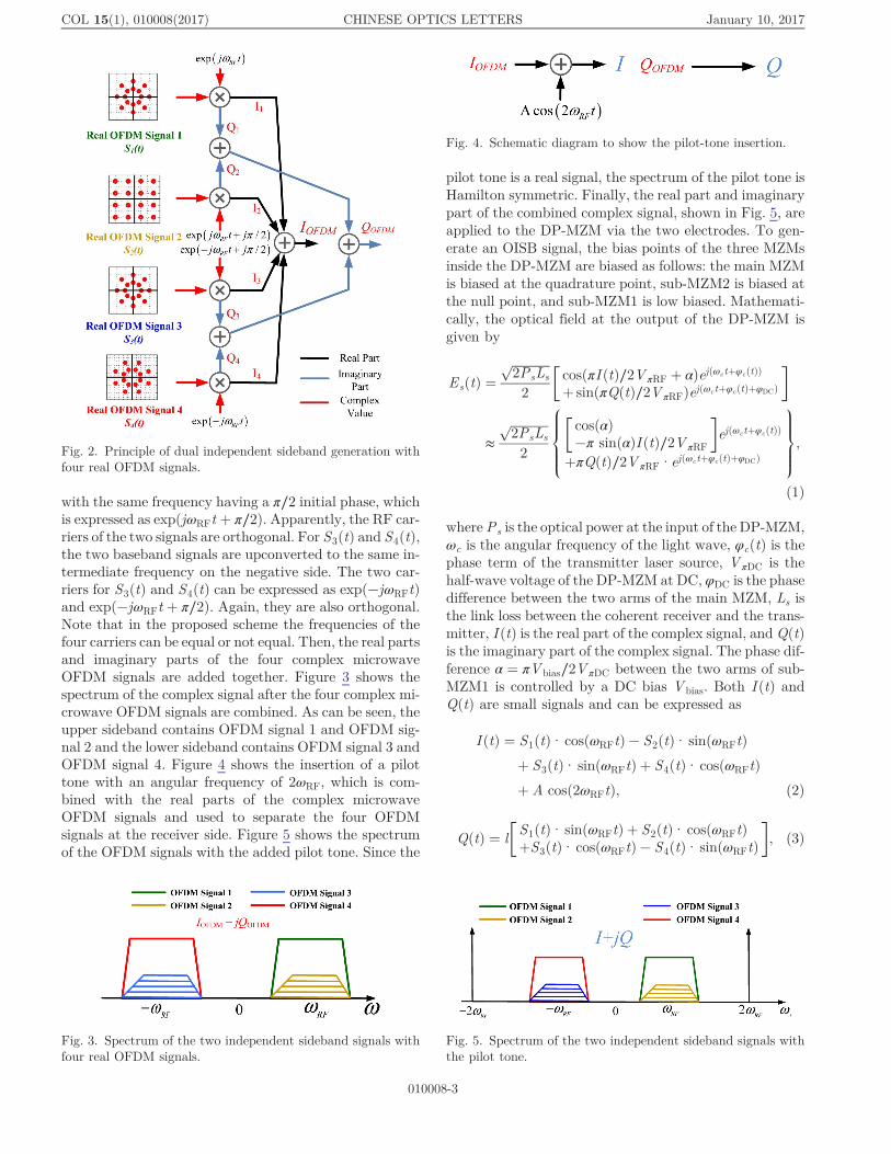
with the same frequency having a π∕2 initial phase, whichis expressed as expðjωRFt þ π∕2Þ. Apparently, the RF car-riers of the two signals are orthogonal. For S3ðtÞ and S4ðtÞ,the two baseband signals are upconverted to the same in-termediate frequency on the negative side. The two car-riers for S3ðtÞ and S4ðtÞ can be expressed as expð−jωRFtÞand expð−jωRFt þ π∕2Þ. Again, they are also orthogonal.Note that in the proposed scheme the frequencies of thefour carriers can be equal or not equal. Then, the real partsand imaginary parts of the four complex microwaveOFDM signals are added together. Figure 3 shows thespectrum of the complex signal after the four complex mi-crowave OFDM signals are combined. As can be seen, theupper sideband contains OFDM signal 1 and OFDM sig-nal 2 and the lower sideband contains OFDM signal 3 andOFDM signal 4. Figure 4 shows the insertion of a pilottone with an angular frequency of 2ωRF, which is com-bined with the real parts of the complex microwaveOFDM signals and used to separate the four OFDMsignals at the receiver side. Figure 5 shows the spectrumof the OFDM signals with the added pilot tone. Since the
pilot tone is a real signal, the spectrum of the pilot tone isHamilton symmetric. Finally, the real part and imaginarypart of the combined complex signal, shown in Fig. 5, areapplied to the DP-MZM via the two electrodes. To gen-erate an OISB signal, the bias points of the three MZMsinside the DP-MZM are biased as follows: the main MZMis biased at the quadrature point, sub-MZM2 is biased atthe null point, and sub-MZM1 is low biased. Mathemati-cally, the optical field at the output of the DP-MZM isgiven by
EsðtÞ ¼�������������2PsLs
p2
�cosðπI ðtÞ∕2V πRF þ αÞejðωctþφcðtÞÞ
þ sinðπQðtÞ∕2V πRFÞejðωctþφcðtÞþφDCÞ
�
≈�������������2PsLs
p2
8>><>>:
�cosðαÞ−π sinðαÞI ðtÞ∕2V πRF
�ejðωctþφcðtÞÞ
þπQðtÞ∕2V πRF·ejðωctþφcðtÞþφDCÞ
9>>=>>;;
(1)
where Ps is the optical power at the input of the DP-MZM,ωc is the angular frequency of the light wave, φcðtÞ is thephase term of the transmitter laser source, V πDC is thehalf-wave voltage of the DP-MZM at DC, φDC is the phasedifference between the two arms of the main MZM, Ls isthe link loss between the coherent receiver and the trans-mitter, I ðtÞ is the real part of the complex signal, and QðtÞis the imaginary part of the complex signal. The phase dif-ference α ¼ πV bias∕2V πDC between the two arms of sub-MZM1 is controlled by a DC bias V bias. Both I ðtÞ andQðtÞ are small signals and can be expressed as
I ðtÞ ¼ S1ðtÞ·cosðωRFtÞ− S2ðtÞ·sinðωRFtÞþ S3ðtÞ·sinðωRFtÞ þ S4ðtÞ·cosðωRFtÞþ A cosð2ωRFtÞ; (2)
QðtÞ ¼ l�S1ðtÞ·sinðωRFtÞ þ S2ðtÞ·cosðωRFtÞþS3ðtÞ·cosðωRFtÞ− S4ðtÞ·sinðωRFtÞ
�; (3)
Fig. 2. Principle of dual independent sideband generation withfour real OFDM signals.
Fig. 3. Spectrum of the two independent sideband signals withfour real OFDM signals.
Fig. 4. Schematic diagram to show the pilot-tone insertion.
Fig. 5. Spectrum of the two independent sideband signals withthe pilot tone.
COL 15(1), 010008(2017) CHINESE OPTICS LETTERS January 10, 2017
010008-3

where S1ðtÞ, S2ðtÞ, S3ðtÞ, and S4ðtÞ are the four basebandreal OFDM signals, ωRF is the center frequency of thefour microwave OFDM signals, A is the amplitude ofthe electrical pilot tone, and l is an attenuation factor.To generate an OISB signal, the optical power forthe two optical sidebands at the output of sub-MZM1(½π sinðαÞI ðtÞ∕2V πRF� exp½jðωct þ φcðtÞÞ�) and sub-MZM2(½πQðtÞ∕2V πRF� exp½jðωct þ φcðtÞ þ φDCÞ�) should beequal, thus l should be equal to sinðαÞ, which is done inthe system by decreasing the electrical power of QðtÞ.Since the main MZM is biased at the quadrature point,φDC can be equal to either π∕2 or −π∕2. Figure 6 showsthe optical spectrum of the OISB signal at the outputof the DP-MZM when φDC is equal to −π∕2. It can be seenthat the signals shown in Fig. 5 are frequency upconvertedto ωc. In addition, optical orthogonal modulation is real-ized. Each sideband contains two OFDM signals whoseoptical subcarriers are orthogonal. Figure 7 shows theoptical spectrum of the OISB signal at the output ofthe DP-MZM when φDC is equal to π∕2. The only differ-ence between the signals shown in Figs. 6 and 7 is that thepositions of the signals at the lower and the upper side-bands are swapped. In addition, to separate the four mi-crowave OFDM signals at the receiver side, the opticalcarrier is partially suppressed to make it have a poweridentical to that of either of the two pilot tones. In thefollowing analysis, we assume that φDC is equal to π∕2.After transmission over an SMF, the optical signal is
coherently detected by a coherent receiver while a free-running LO laser source is used as an LO source. Theoptical field of the light wave from the LO laser sourceis given by
ELOðtÞ ¼������������2PLO
pejðωLOtþφLOðtÞÞ; (4)
where PLO is the optical power, φLOðtÞ is the phase term,and ωLO is the angular frequency.
The optical signal from the transmitter and the lightwave from the LO laser source are co-polarized and areapplied to a 90° optical hybrid. At the four outputs ofthe 90° optical hybrid, we have four optical signals withthe electrical fields given by
E1 ¼����L
pðEs þ ELOÞ; (5)
E2 ¼����L
pðEs − ELOÞ; (6)
E3 ¼����L
pðEs þ ELOejπ∕2Þ; (7)
E4 ¼����L
pðEs − ELOejπ∕2Þ; (8)
where L is the insertion loss caused by the 90° opticalhybrid.
By applying E1 and E2, and E3 and E4, to two balancedphotodetectors we have two output photocurrentsgiven by
IPD1 ¼ 2RL��������������������PsPLOLs
pðIEC1 þ IPR1 þ IPL1
þ S lower1 þ Supper1Þ; (9)
IEC1 ¼ cosðαÞ cos½ðΔωÞt þ φðtÞ�;IPR1 ¼ −0.5AB cos½ðΔωÞt þ φðtÞ þ 2ωRFt�;IPL1 ¼ −0.5AB cos½ðΔωÞt þ φðtÞ− 2ωRFt�;
S lower1 ¼ −BS1ðtÞ cos½ðΔωÞt þ φðtÞ− ωRFt�− BS2ðtÞ·sin½ðΔωÞt þ φðtÞ− ωRFt�;
Supper1 ¼ −BS3ðtÞ sin½ðΔωÞt þ φðtÞ þ ωRFt�− BS4ðtÞ cos½ðΔωÞt þ φðtÞ þ ωRFt�;
B ¼ πl∕2V πRF ¼ π sinðαÞ∕2V πRF;
and
IPD2 ¼ 2RL��������������������PsPLOLs
pðIEC2 þ IPR2 þ IPL2
þ S lower2 þ Supper2Þ; (10)
IEC2 ¼ cosðαÞ sin½ðΔωÞt þ φðtÞ�;IPR2 ¼ −0.5AB sin½ðΔωÞt þ φðtÞ þ 2ωRFt�;IPL2 ¼ −0.5AB sin½ðΔωÞt þ φðtÞ− 2ωRFt�;
S lower2 ¼ −BS1ðtÞ sin½ðΔωÞt þ φðtÞ− ωRFt�þ BS2ðtÞ cos½ðΔωÞt þ φðtÞ− ωRFt�;
Supper2 ¼ BS3ðtÞ cos½ðΔωÞt þ φðtÞ þ ωRFt�− BS4ðtÞ sin½ðΔωÞt þ φðtÞ þ ωRFt�;
B ¼ πl∕2V πRF ¼ π sinðαÞ∕2V πRF;
where Δω ¼ ωc − ωLO is the frequency difference betweenthe transmitter and the LO laser sources, φðtÞ is the phasenoise introduced by the transmitter laser source and theLOlaser source, φðtÞ ¼ φcðtÞ− φLOðtÞ, andR is the responsiv-ity of the PD. As can be seen, the photocurrent IPD1 con-tains one electrical carrier (IEC1), one left pilot tone (IPL1),
Fig. 6. Optical spectrum at the output of the DP-MZM forφDC ¼ −π∕2.
Fig. 7. Optical spectrum at the output of the DP-MZM forφDC ¼ π∕2.
COL 15(1), 010008(2017) CHINESE OPTICS LETTERS January 10, 2017
010008-4
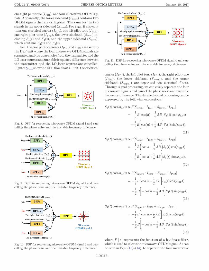
one right pilot tone (IPR1), and fourmicrowave OFDM sig-nals. Apparently, the lower sideband (Slower1) contains twoOFDM signals that are orthogonal. The same for the twosignals in the upper sideband (Supper1). For IPD2, it also con-tains one electrical carrier (IEC2), one left pilot tone (IPL2),one right pilot tone (IPR2), the lower sideband (Slower2) in-cluding S1ðtÞ and S2ðtÞ, and the upper sideband (Supper2),which contains S3ðtÞ and S4ðtÞ.Then, the two photocurrents (IPD1 and IPD2) are sent to
the DSP unit where the four microwave OFDM signals areseparated and the phase noise from the transmitter and theLO laser sources andunstable frequency difference betweenthe transmitter and the LO laser sources are cancelled.Figures 8–11 show theDSP flow charts. First, the electrical
carrier (IEC1), the left pilot tone (IPL1), the right pilot tone(IPR1), the lower sideband (S lower1), and the uppersideband (Supper1) are separated via electrical filters.Through signal processing, we can easily separate the fourmicrowave signals and cancel the phase noise and unstablefrequency difference. The detailed signal processing can beexpressed by the following expressions.
S1ðtÞ cosðωRFtÞ ∝ F ½S lower1·IEC1 þ S lower1·IPL1�
¼ −12B�cosðαÞ− 1
2AB
�S1ðtÞ cosðωRFtÞ
−12B�cosðαÞ þ 1
2AB
�S2ðtÞ sinðωRFtÞ;
(11)
S2ðtÞ cosðωRFtÞ ∝ F ½S lower1·IEC2 þ S lower1·IPL2�
¼ −12B�cos α−
12AB
�S2ðtÞ cosðωRFtÞ
−12B�cos αþ 1
2AB
�S1ðtÞ sinðωRFtÞ;
(12)
S3ðtÞ cosðωRFtÞ ∝ F ½Supper1·IEC2 þ Supper1·IPR2�
¼ −12B�cos α−
12AB
�S3ðtÞ cosðωRFtÞ
−12B�− cos α−
12AB
�S4ðtÞ sinðωRFtÞ;
(13)
S4ðtÞ cosðωRFtÞ ∝ F ½Supper1·IEC1 þ Supper·IPR1�
¼ −12B�cos α−
12AB
�S4ðtÞ cosðωRFtÞ
−12B�− cos α−
12AB
�S3ðtÞ sinðωRFtÞ;
(14)
where F [·] represents the function of a bandpass filter,which is used to select themicrowave OFDM signal. As canbe seen in Eqs. (11)–(14), to separate the four microwave
Fig. 8. DSP for recovering microwave OFDM signal 1 and can-celling the phase noise and the unstable frequency difference.
Fig. 9. DSP for recovering microwave OFDM signal 2 and can-celling the phase noise and the unstable frequency difference.
Fig. 10. DSP for recovering microwave OFDM signal 3 and can-celling the phase noise and the unstable frequency difference.
Fig. 11. DSP for recovering microwave OFDM signal 4 and can-celling the phase noise and the unstable frequency difference.
COL 15(1), 010008(2017) CHINESE OPTICS LETTERS January 10, 2017
010008-5

OFDM signals, cosðαÞ should be equal to −0.5BA. Thus,the power for the electrical carrier and either of the pilottones is controlled equally. Note that the upper sideband,lower sideband, the carriers, and the pilot tones have thesame phase noise and unstable frequency difference intro-duced from the transmitter and the LO laser sources;through microwave mixing between a sideband and oneof the pilot tones or carriers, the phase noise andthe unstable frequency difference can be cancelled. Ascan be seen from Eqs. (11)–(14), the four microwaveOFDM signals are free from the phase noise and unstablefrequency difference.To verify that the proposed coherent MWP link can
transmit, detect, and separate the four microwave OFDMsignals, an experiment is performed based on thesetup shown in Fig. 1. A linearly-polarized CW light at1550.435 nm from a tunable laser source (TLS, AgilentN7714A) with a linewidth of 100 kHz and an optical powerof 16 dBm is sent to the DP-MZM (JDSU) via a polariza-tion controller (PC1). The two signals I ðtÞ andQðtÞ appliedto the DP-MZM are generated by an arbitrary waveformgenerator (AWG,KeysightM8915A) with a program com-posed according to the flow chart shown in Fig. 2 andloaded to the AWG to generate the two signals. BothI ðtÞ andQðtÞ contain four different microwave OFDM sig-nals with an identical center frequency at 2.91 GHz. Themodulation format for three of the four OFDM signals(OFDM Signal 1, OFDM Signal 3, and OFDM Signal 4)is star 16-QAM. The data rate is 1 Gbps each. The otherOFDM signal (OFDM Signal 2) is a rectangular 16-QAMwith a data rate of 1.5Gbps. In the signal I ðtÞ the frequencyof the electrical pilot tone is 5.82 GHz and the amplitude is0.3548 V. As indicated, since cosðαÞ should be equal to−0.5AB, thus α should be equal to −1.527. Sub-MZM1is low biased to introduce a phase shift of −1.527 andsub-MZM2 is biased at the null point, while the mainMZM is biased at the quadrature point (φDC ¼ π∕2).The DP-MZM has a bandwidth of 10 GHz and a half-wavevoltage of around 6.33 V. Then, the generated OISB signal(the lower sideband carries OFDM Signal 1 and OFDMSignal 2, while the upper sideband carries OFDM Signal3 and OFDM Signal 4) with two optical pilot tones andan optical carrier are sent to the coherent receiver over a10 km SMF. At the receiver, coherent detection (DiscoverySemiconductors DP-QPSK 40/100 Gbps CoherentReceiver Lab Buddy) with a free running LO laser source(TLS, Yokogawa AQ2201) operating at 1550.485 nm isperformed to detect the optical signal. The LO laser sourcehas a linewidth of 1 MHz and an optical power of 9 dBm.Through tuning PC2 and PC3, the light wave from the LOlaser source is co-polarized with the received optical signal.Note that in a practical system, PC2 can be replaced by adynamic PC, to accommodate the random polarizationstate of the input optical signal[16]. At the output of thecoherent receiver two photocurrents are generated thatare sampled by a digital storage oscilloscope (AgilentDSO-X 93204A) with a sampling rate of 80 GSa/s. Then,the signal is processed offline in a computer.
We would like to point out that, according to the analy-sis [Eqs. (11) and (14)], the signal processing functions canbe realized using pure analog signal processing where ana-log circuits function as splitters, bandpass filters, andmixers, thus, a high speed analog-to-digital converter(ADC) is not needed. In addition, since no ELOs areneeded at the receiver the system, complexity and costwould be significantly reduced.
Figure 12 shows the spectrum of the photocurrent ofIPD1. As indicated in Fig. 6 or Fig. 7, the lower sidebandcontains one 1 Gbps microwave OFDM signal and one1.5 Gbps microwave OFDM signal (Signal 1 and Signal2), and the upper sideband contains two 1 Gbps micro-wave OFDM signals (Signal 3 and Signal 4).
To verify the performance of the coherent MWP link,the error vector magnitude (EVMs) and estimated BERsof the four microwave OFDM signals as a function of re-ceived optical power are measured back-to-back and with10 km fiber transmission. Figure 13 shows the EVMs atdifferent received optical power levels for the four OFDMsignals and Fig. 14 shows the BERs at different receivedoptical power levels for the four OFDM signals. As can beseen, after 10 km transmission, even the received optical
Fig. 12. Spectrum of the signal at the output of the coherentreceiver (IPD1).
Fig. 13. EVMs at different received optical power levels for thefour OFDM signals, S1: Signal 1, S2: Signal 2, S3: Signal 3, S4:Signal 4.
COL 15(1), 010008(2017) CHINESE OPTICS LETTERS January 10, 2017
010008-6

power is only −20.3 dBm; the raw BERs for the micro-wave OFDM signals are still less than 3 × 10⁻³ (FECthreshold, 6.7% overhead), which would enable error-freetransmission. The power penalty caused by the fibertransmission is less than 1 dB, which is small and canbe ignored. The corresponding constellations of the signalsare shown in Fig. 15. As can be seen, the constellations areclear after 10 km transmission, which confirms that thefour microwave OFDM signals are well separated andthe phase noise and the unstable frequency differenceare effectively cancelled. In addition, it can be seen thatthe power penalty caused by the 10 km SMF transmissionis very small, about 1 dB, and can be ignored.
In conclusion, a 4 × 4 coherent MWP link based onOISB modulation and optical orthogonal modulation isproposed and experimentally demonstrated. The proposedscheme is able to support the transmission of four micro-wave OFDM signals with an identical center frequencywithout using electrical FDM and optical wavelength-division multiplexing. If polarization multiplexing is em-ployed, the data transmission capacity would be doubled,that is, eight microwave signals can be transmitted, whichwould enable 8 × 8 MIMO. In the proposed scheme, noELOs are needed for frequency conversion at the receiver,which simplifies significantly the system. In addition, sincethe OISB modulation and optical orthogonal modulationare employed, the spectral efficiency is improved. The pro-posed approach is experimentally evaluated. Three 1 GbpsOFDM signals and one 1.5 Gbps OFDM signal at an iden-tical microwave carrier frequency of 2.91 GHz are trans-mitted over a 10 km SMF. The estimated BERs show thaterror-free transmission is ensured even for a low receivedoptical power of−20.3 dBm and the power penalty causedby the 10 km fiber is small and can be ignored.
This work was supported by the Natural Sciences andEngineering Research Council of Canada (NSERC).
References1. J. P. Yao, J. Lightwave Technol. 27, 314 (2009).2. J. Capmany and D. Novak, Nat. Photonics 1, 319 (2007).3. A. Pizzinat, P. Chanclou, F. Saliou, and T. Diallo, J. Lightwave
Technol. 33, 1077 (2015).4. J. Wang, Z. Yu, K. Ying, J. Zhang, F. Lu, M. Xu, and G.-K. Chang,
in Proceedings of Optical Fiber Communication Conference (2016),paper W1H.2.
5. X. Liu, H. Zeng, N. Chand, and F. Effenberger, J. Lightwave Tech-nol. 34, 1556 (2016).
6. X. Liu, F. Effenberger, N. Chand, L. Zhou, and H. Lin, inProceedings of Asia Communications Photonics Conference(2014), paper AF4B.5.
7. X. Liu, F. Effenberger, N. Chand, L. Zhou, andH. Lin, inProceedingsof Optical Fiber Communication Conference (2015), paper M2J.2.
8. M. Zhu, X. Liu, N. Chand, F. Effenberger, and G.-K. Chang, inProceedings of Optical Fiber Communication Conference (2015),paper M2J.3.
9. H.-T. Huang, C.-T. Lin, Y.-T. Chiang, C.-C. Wei, and C.-H. Ho, J.Lightwave Technol. 32, 3660 (2014).
10. C.-T. Lin, C.-H. Ho, H.-T. Huang, and Y.-H. Cheng, Opt. Lett. 39,1358 (2014).
11. J. Yu, X. Li, and N. Chi, Opt. Express 21, 22885 (2013).12. J. Xiao, J. Yu, X. Li, Y. Xu, Z. Zhang, and L. Chen, Opt. Lett. 40,
998 (2015).13. N. P. Diamantopoulos, S. Inudo, Y. Yoshida, A. Maruta, A. Kanno,
P. T. Dat, T. Kawanishi, R. Maruyama, N. Kuwaki, S. Matsuo, andK. Kitayama, in Proceedings of Optical Fiber CommunicationConference (2015), paper W4G.2.
14. Y. Chen, T. Shao, A.Wen, and J. P. Yao, Opt. Lett. 39, 1509 (2014).15. X. Chen and J. P. Yao, J. Lightwave Technol. 29, 3091 (2015).16. X. S. Yao, L. S. Yan, B. Zhang, A. E. Willner, and J. Jiang, Opt.
Express 15, 7407 (2007).
-23 -22 -21 -20 -19 -18 -1710-4
10-3
10-2
Received Optical Power (dBm)
Bit
Err
or R
ate
S1 w/ 10 kmS2 w/ 10 kmS3 w/ 10 kmS4 w/ 10 kmS1 w/o 10 kmS2 w/o 10 kmS3 w/o 10 kmS4 w/o 10 km
3x10⁻³
Fig. 14. BERs at different received optical power levels for thefour OFDM signals, S1: Signal 1, S2: Signal 2, S3: Signal 3, S4:Signal 4.
Fig. 15. Measured constellations for the recovered microwaveOFDM signals (fiber length: 10 km, the received opticalpower: −20.3 dBm). (a) Signal 1, (b) Signal 2, (c) Signal 3,and (d) Signal 4.
COL 15(1), 010008(2017) CHINESE OPTICS LETTERS January 10, 2017
010008-7


![Novel Design for Photonic Crystal Ring Resonators Based ...jopn.miau.ac.ir/article_3046_01eb01affabdaa909e9328069782f311.pdf · employing photonic crystals [4]. In recent years, photonic](https://img.pdfslide.net/doc/110x75/5e7ed386707cf3599e6c8522/novel-design-for-photonic-crystal-ring-resonators-based-jopnmiauacirarticle304601eb01affabd.jpg)