Embed Size (px)
Citation preview
�92 CEMENT INTERNATIONAL 4 5/2006 4 VOL. 4
PROC
ESSI
NG
ZUSAMMENFASSUNG
Long distance belt conveyors have always been a challenge
for drive and control applications. There are several methods
of applying the drive. Different drive systems have to be
provided to suit the topographical conditions, the material
to be transported, the environmental requirements and the
operating methods. This article describes the drive system
for a downhill conveyor between the quarry area and the raw
material section of a cement plant in Switzerland. Because
of the operational requirements the drive had to have an
adjustable speed and should be capable of regenerating the
power on the downhill section. A new technique, the Active
Front End (AFE) technology, was applied and is described in
detail. Nowadays all operating processes are monitored by
sophisticated control systems. One of the big advantages
claimed for this technology is that it is “extremely network
friendly”. The article also describes how all the environmen-
tal requirements are fulfilled by the use of a tube conveyor
and examines the energy balance from the aspect of the
active power taken out of the network and the regenerative
power fed back into the network.3
Auslegung und Betrieb von Gurtförderanlagen über große
Förderlängen waren schon immer große ingenieurtech-
nische Herausforderungen sowohl für die Antriebsgestal-
tung als auch für die Steuerung. In Abhängigkeit von den
topografischen Bedingungen, vom zu transportierenden
Material, von der Erfüllung sowohl umwelt- als auch
betriebstechnischer Anforderungen, können verschiedene
Antriebssysteme eingesetzt werden. In diesem Beitrag wird
für eine Gurtförderanlage mit einem abwärts fördernden
Steckenabschnitt zwischen dem Tagebau und dem Roh-
materiallager eines schweizerischen Zementwerks das
Antriebssystem beschrieben. Aufgrund der betrieblichen
Erfordernisse wurden die Antriebe mit veränderlicher
Geschwindigkeit ausgelegt und sind für den abwärts för-
dernden Streckenabschnitt auch zur Energierückgewinnung
geeignet. Dabei gelangte die neue, als Activ-Front-End-
Technologie bezeichnete Antriebstechnik zur Anwendung,
die im Detail beschrieben wird. Alle Betriebsabläufe werden
heutzutage mit intelligenten Kontrollsystemen überwacht.
Einer der großen Vorteile, die für die Anwendung dieses
neuen Antriebssystems sprechen, ist seine große „Netz-
freundlichkeit“. Der Beitrag berichtet auch über die zahl-
reichen umwelttechnischen Auflagen, die erfüllt werden
mussten und gewährt einen Blick auf die Energiebilanz, die
sowohl die aktive Versorgung der Antriebe aus dem Netz,
als auch die regenerative Energielieferung in das Netzwerk
enthält.3
SUMMARY
4Dipl.-Ing. P. Lüchinger, Cement Vigier, Péry, Dipl.-Ing. U. Maier, ALRO Antriebstechnik GmbH,Rudolfstetten, Dipl.-Ing. R.A. Errath, ABB Schweiz AG, Baden-Dättwil, Switzerland
*) Revised version of a lecture given by the second author at the IEEE-IAS/PCATechnical Cement Conference held in Phoenix, Missouri, USA in April 2006.(English text supplied by the author)
Luechinger.indd 92 17.10.2006 9:33:41 Uhr
�Reprint from Cement International | May 2006 CEMENT INTERNATIONAL 4 5/2006 4 VOL. 4 93
PROC
ESSI
NG
Active Front End technology (AFE) as applied to a downhillconveyor*)
Activ-Front-End-Technologie (AFE) im Einsatz bei einem abwärts förderndenGurtförderer
1 Introduction
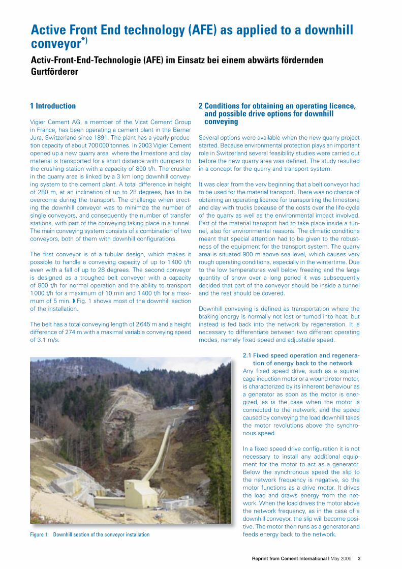
Vigier Cement AG, a member of the Vicat Cement Groupin France, has been operating a cement plant in the BernerJura, Switzerland since 1891. The plant has a yearly produc-tion capacity of about 700000 tonnes. In 2003 Vigier Cementopened up a new quarry area where the limestone and claymaterial is transported for a short distance with dumpers tothe crushing station with a capacity of 800 t/h. The crusherin the quarry area is linked by a 3 km long downhill convey-ing system to the cement plant. A total difference in heightof 280 m, at an inclination of up to 28 degrees, has to beovercome during the transport. The challenge when erect-ing the downhill conveyor was to minimize the number ofsingle conveyors, and consequently the number of transferstations, with part of the conveying taking place in a tunnel.The main conveying system consists of a combination of twoconveyors, both of them with downhill configurations.
The first conveyor is of a tubular design, which makes itpossible to handle a conveying capacity of up to 1400 t/heven with a fall of up to 28 degrees. The second conveyoris designed as a troughed belt conveyor with a capacityof 800 t/h for normal operation and the ability to transport1000 t/h for a maximum of 10 min and 1400 t/h for a maxi-mum of 5 min. Fig. 1 shows most of the downhill sectionof the installation.
The belt has a total conveying length of 2645 m and a heightdifference of 274 m with a maximal variable conveying speedof 3.1 m/s.
2 Conditions for obtaining an operating licence,and possible drive options for downhillconveying
Several options were available when the new quarry projectstarted. Because environmental protection plays an importantrole in Switzerland several feasibility studies were carried outbefore the new quarry area was defined. The study resultedin a concept for the quarry and transport system.
It was clear from the very beginning that a belt conveyor hadto be used for the material transport. There was no chance ofobtaining an operating licence for transporting the limestoneand clay with trucks because of the costs over the life-cycleof the quarry as well as the environmental impact involved.Part of the material transport had to take place inside a tun-nel, also for environmental reasons. The climatic conditionsmeant that special attention had to be given to the robust-ness of the equipment for the transport system. The quarryarea is situated 900 m above sea level, which causes veryrough operating conditions, especially in the wintertime. Dueto the low temperatures well below freezing and the largequantity of snow over a long period it was subsequentlydecided that part of the conveyor should be inside a tunneland the rest should be covered.
Downhill conveying is defined as transportation where thebraking energy is normally not lost or turned into heat, butinstead is fed back into the network by regeneration. It isnecessary to differentiate between two different operatingmodes, namely fixed speed and adjustable speed.
2.1 Fixed speed operation and regenera-tion of energy back to the network
Any fixed speed drive, such as a squirrelcage induction motor or a wound rotor motor,is characterized by its inherent behaviour asa generator as soon as the motor is ener-gized, as is the case when the motor isconnected to the network, and the speedcaused by conveying the load downhill takesthe motor revolutions above the synchro-nous speed.
In a fixed speed drive configuration it is notnecessary to install any additional equip-ment for the motor to act as a generator.Below the synchronous speed the slip tothe network frequency is negative, so themotor functions as a drive motor. It drivesthe load and draws energy from the net-work. When the load drives the motor abovethe network frequency, as in the case of adownhill conveyor, the slip will become posi-tive. The motor then runs as a generator andfeeds energy back to the network.Figure 1: Downhill section of the conveyor installation
Luechinger.indd 93 17.10.2006 9:33:45 Uhr
� Reprint from Cement International | May 2006 94 CEMENT INTERNATIONAL 4 5/2006 4 VOL. 4
PROC
ESSI
NGUnder adjustable speed conditions the drive must have four-quadrant characteristics in order to run like a motor or a gen-erator. Older configurations have used, and are still using,network input circuits equipped with thyristors. These inputcircuits are relatively simple, because they are network com-mutated. The operative function does fulfil the requirementsin terms of adjustable speed and also of regeneration. How-ever, if the network is disconnected during the regenerativeperiod, i.e. if the MV breaker opens for some reason, thenthe equipment will lose the commutation and cause a shortcircuit in the input thyristor bridge. Short circuits alwaysinvolve burnt fuses.
Modern configurations use an “Active Front End” (AFE) cir-cuit. Equipment with this configuration does not have thenegative behaviour mentioned with the thyristors. There areno burnt fuses if the system becomes disconnected fromthe network and the equipment will be ready again as soonas the power is restored.
2.2 Stopping the conveyor by braking the drive2.2.1 Fixed speed drivesSquirrel cage induction motors have very restricted brakingcapabilities and are only used on smaller installations. Theonly options are either to switch the motor off and brake witha mechanical brake, or else brake with a reverse current. Thelatter procedure is not used very often because reverse-cur-rent braking applies a heavy reverse torque at the instant ofswitching over, and the belt may start to slip, with the resultthat the current to the network is higher than permitted.
The wound rotor motor has more options for controlledbraking. This configuration operates with higher power, andworks on a medium voltage level. The motor is equippedwith a secondary starter and a DC injection brake. The brak-ing torque can be adjusted to suit the requirements.
2.2.2 Adjustable speed drivesThe modern state-of-the-art downhill configuration is basedon an adjustable speed drive with four-quadrant (4Q) char-acteristics, which means acceleration and braking in the for-ward direction, and acceleration and braking in the reversedirection. With the 4Q drive system there is no change inpolarity of the torque when the speed of a running drive isreduced to zero. The change in speed will always causesmooth reactions in the belt. The speed can be decreased
to zero. It is even possible to hold the position at zero speedwith a 4Q drive.
A low voltage version is generally utilized for the smallertransport systems. MV equipment is used for larger down-hill conveyors, with capacities in the range of 800 kW andabove, especially if the belt conveyor is long. The energy canbe regenerated to the network.
3 Case study from Cement Vigier
The first question when planning a drive system for a con-veyor is whether it should be driven by fixed speed motorsor variable speed drives. To answer this question, it is nec-essary to identify the additional capital costs for the vari-able speed drives, and compare them with the advantagesachieved and with the operating and service costs. It is alsonecessary to compare the respective service lives of theconveying system, the belt, the mechanical componentsand the structure.
3.1 Basic requirements for belt conveyor systemsThe belt is the most expensive and most exposed com-ponent of a conveyor. In addition to the selection of an ad-equate drive system, it is necessary to ensure that the stresson the belt is kept within the design limits. This basic require-ment must be maintained for all possible operating condi-tions, including emergency situations.
The load sharing of the different drives has to be coordinatedin such a way that all the associated drives develop a similartorque even under partial load conditions and during starting/stopping procedures, but especially under full load or in emer-gency situations. It has to be ensured that the torque peakstransmitted to the belt are never greater than 20 to 30 %of the required torque, regardless of whether such peaksoccur in the acceleration, operational or deceleration phases.The drive system for the belt must be able to allow a main-tenance speed of 10 % of the nominal speed in both direc-tions. Torque peaks must be controlled and limited to a per-mitted magnitude for all the mechanical components suchas gearboxes, couplings, shafts etc. Possible belt slippinghas to be monitored.
The belt must be started and stopped very gently and in a con-trolled manner so that the belt is not overstressed. This can
be achieved with an S-shaped acceleration anddeceleration ramp. In cases where the belt con-veyor is very long it may even be necessary tostart the drives on the head end before the oneson the tail end in order to tighten the belt first.
The service speed is normally approximately10 % of the nominal belt speed. A separate low-speed motor system is required if DOL motorsare used. With the variable-speed drive sys-tem all speeds can be achieved with the sameequipment.
3.2 Conveyor brakingDepending on the topology no braking duringoperation is required for horizontal conveyingsystems. If the terrain is ascending and descend-ing it may be necessary to use partial brakingwhile the belt is being loaded and unloaded.Downhill conveyors require continuous braking
Parameter UnitTube beltconveyor
Troughed beltconveyor
Tube beltconveyor
Distance between centres m 244.46 2 397 550
Difference in altitude m -81 -193 +4.1
Max. slope degrees 28 5 –
Nominal tube diameter mm 400 – 400
Belt width mm 1 600 1 200 1 600
Trough – –Three-part,40 degrees
–
Belt type – EP1000/4 ST1800 –
Idler diameter mm 108 133 –
Installed motor power kW 2 x 160 3 x 160 1 x 160; 1 x 55
Vertical curves m 3 x 120 – –
Horizontal curves m – 5 x 2 000 –
Belt speed m/s 3 3 3
Table 1: List of the technical parameters for the three belt conveyors
Luechinger.indd 94 17.10.2006 9:33:48 Uhr
�Reprint from Cement International | May 2006 CEMENT INTERNATIONAL 4 5/2006 4 VOL. 4 95
PROC
ESSI
NG
during operation if the friction losses are smaller than theenergy regenerated by the load.
Every downhill belt conveyor has to be equipped with anemergency brake. This has to be activated if one of the pull-ropes, and with it the corresponding emergency switch, isoperated as well as in cases where excessive speed canoccur. An electrical braking system cannot fulfil the safetystandards because of possible power loss or defects in theelectrical system. An electrical brake system is often usedas the main brake during normal operation to decelerate theconveyor from high to zero speed in order to avoid exces-sive wear of the mechanical brake, while the mechanical discbrake takes over the shutdown and emergency situations.When sizing the mechanical brake it has to be borne in mindthat it is necessary to brake the fully loaded conveyor frommaximum speed to zero speed.
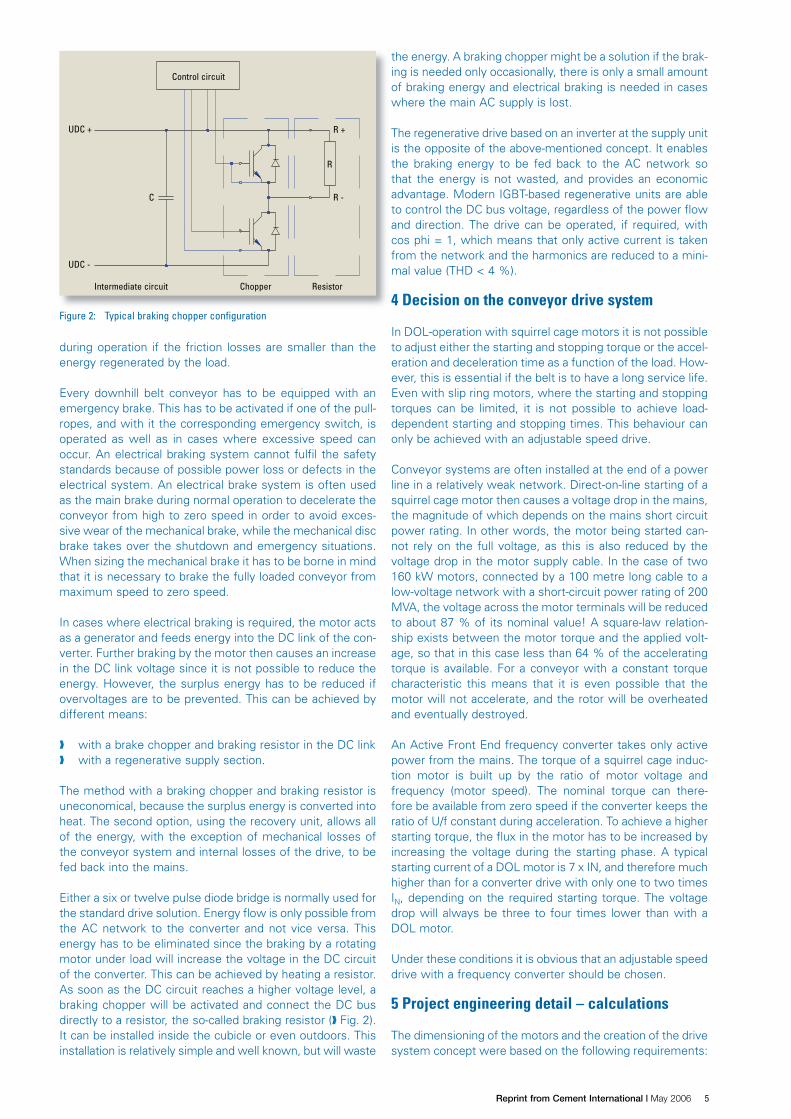
In cases where electrical braking is required, the motor actsas a generator and feeds energy into the DC link of the con-verter. Further braking by the motor then causes an increasein the DC link voltage since it is not possible to reduce theenergy. However, the surplus energy has to be reduced ifovervoltages are to be prevented. This can be achieved bydifferent means:
with a brake chopper and braking resistor in the DC link with a regenerative supply section.
The method with a braking chopper and braking resistor isuneconomical, because the surplus energy is converted intoheat. The second option, using the recovery unit, allows allof the energy, with the exception of mechanical losses ofthe conveyor system and internal losses of the drive, to befed back into the mains.
Either a six or twelve pulse diode bridge is normally used forthe standard drive solution. Energy flow is only possible fromthe AC network to the converter and not vice versa. Thisenergy has to be eliminated since the braking by a rotatingmotor under load will increase the voltage in the DC circuitof the converter. This can be achieved by heating a resistor.As soon as the DC circuit reaches a higher voltage level, abraking chopper will be activated and connect the DC busdirectly to a resistor, the so-called braking resistor ( Fig. 2).It can be installed inside the cubicle or even outdoors. Thisinstallation is relatively simple and well known, but will waste
the energy. A braking chopper might be a solution if the brak-ing is needed only occasionally, there is only a small amountof braking energy and electrical braking is needed in caseswhere the main AC supply is lost.
The regenerative drive based on an inverter at the supply unitis the opposite of the above-mentioned concept. It enablesthe braking energy to be fed back to the AC network sothat the energy is not wasted, and provides an economicadvantage. Modern IGBT-based regenerative units are ableto control the DC bus voltage, regardless of the power flowand direction. The drive can be operated, if required, withcos phi = 1, which means that only active current is takenfrom the network and the harmonics are reduced to a mini-mal value (THD < 4 %).
4 Decision on the conveyor drive system
In DOL-operation with squirrel cage motors it is not possibleto adjust either the starting and stopping torque or the accel-eration and deceleration time as a function of the load. How-ever, this is essential if the belt is to have a long service life.Even with slip ring motors, where the starting and stoppingtorques can be limited, it is not possible to achieve load-dependent starting and stopping times. This behaviour canonly be achieved with an adjustable speed drive.
Conveyor systems are often installed at the end of a powerline in a relatively weak network. Direct-on-line starting of asquirrel cage motor then causes a voltage drop in the mains,the magnitude of which depends on the mains short circuitpower rating. In other words, the motor being started can-not rely on the full voltage, as this is also reduced by thevoltage drop in the motor supply cable. In the case of two160 kW motors, connected by a 100 metre long cable to alow-voltage network with a short-circuit power rating of 200MVA, the voltage across the motor terminals will be reducedto about 87 % of its nominal value! A square-law relation-ship exists between the motor torque and the applied volt-age, so that in this case less than 64 % of the acceleratingtorque is available. For a conveyor with a constant torquecharacteristic this means that it is even possible that themotor will not accelerate, and the rotor will be overheatedand eventually destroyed.
An Active Front End frequency converter takes only activepower from the mains. The torque of a squirrel cage induc-tion motor is built up by the ratio of motor voltage andfrequency (motor speed). The nominal torque can there-fore be available from zero speed if the converter keeps theratio of U/f constant during acceleration. To achieve a higherstarting torque, the flux in the motor has to be increased byincreasing the voltage during the starting phase. A typicalstarting current of a DOL motor is 7 x IN, and therefore muchhigher than for a converter drive with only one to two timesIN, depending on the required starting torque. The voltagedrop will always be three to four times lower than with aDOL motor.
Under these conditions it is obvious that an adjustable speeddrive with a frequency converter should be chosen.
5 Project engineering detail – calculations
The dimensioning of the motors and the creation of the drivesystem concept were based on the following requirements:
Figure 2: Typical braking chopper configuration
Intermediate circuit Chopper Resistor
UDC -
UDC +
Control circuit
C
R +
R -
R
Luechinger.indd 95 17.10.2006 9:33:49 Uhr
� Reprint from Cement International | May 2006 96 CEMENT INTERNATIONAL 4 5/2006 4 VOL. 4
PROC
ESSI
NG
creation of the simulation and calculation model for allpossible operating and loading conditions, includingsimulation of starting, stopping and emergency stoppingscenarios,
power trip under full, half and empty loading conditions, maximum allowed belt tension, in terms of mechanical
belt stress and belt slip limits, maximum utilization of equal drive components and
motor sizes in order to minimize the number of spareparts components,
allowance for future increases in performance.
The result of the study led to the following concept:
Downhill conveyor 1:Tube conveyor, with two motors on a common drum at thetail end.
Downhill Conveyor 2:Troughed belt conveyor in the tunnel, with a total of threemotors – two motors on the common first drum and onemotor on the second drum.
All five motors were of the same power with the same physi-cal dimensions.
Each drive system consisted of a frequency converter driv-ing a squirrel cage motor of 160 kW, a disc brake betweenthe motor and gear unit (the purpose of the disc brake is tohold the loaded belt when it is out of operation, when it isstationary, and, if there is a power dip, to brake the drivesystem safely to zero speed), a gear unit and a load cellto measure the torque, in order to avoid over-tension andstresses in the belt.
Under normal operating conditions the motors run at a pre-defined speed. The speed can be decreased below the nomi-nal speed, for whatever reason, but can also be increasedabove the nominal speed in order to fill up an empty stock-pile, etc. During the belt starting and stopping procedure thetorque developed by the drive follows the S reference curve,
and no excessive belt stresses are produced. Special atten-tion is given to the dynamical belt stress parameters duringthe starting and stopping procedures.
The drive power is determined by the following calculation:
(1)
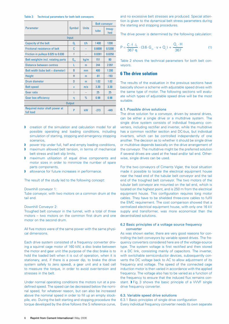
Table 2 shows the technical parameters for both belt con-veyors.
6 The drive solution
The results of the evaluation in the previous sections havebasically shown a scheme with adjustable speed drives withthe same type of motor. The following sections will evalu-ate which types of adjustable speed drive will be the mostsuitable.
6.1. Possible drive solutionsThe drive solution for a conveyor, driven by several drives,can be either a single drive or a multidrive system. Thesingle drive system consists of individual frequency con-verters, including rectifier and inverter, while the multidrivehas a common rectifier section and DC-bus, but individualinverters, which can be controlled independently of oneanother. The decision as to whether it should be single driveor multidrive depends basically on the drive arrangement ofthe conveyor. The multidrive might be the preferred solutionif several drives are used at the head and/or tail end. Other-wise, single drives can be used.
For the two conveyors of Ciments Vigier, the local situationmade it possible to locate the electrical equipment housenear the head end of the tubular belt conveyor and the tailend of the troughed belt conveyor. The two motors of thetubular belt conveyor are mounted on the tail end, which islocated on the highest point, and is 250 m from the electricalequipment house. This configuration requires long motorcables. They have to be shielded three-core cables to fulfilthe EMC requirement. The cost comparison showed that acentralized electrical equipment house, with only one 16 kVsupply and transformer, was more economical than thedecentralized solutions.
6.2 Basic principles of a voltage source frequencyconverter
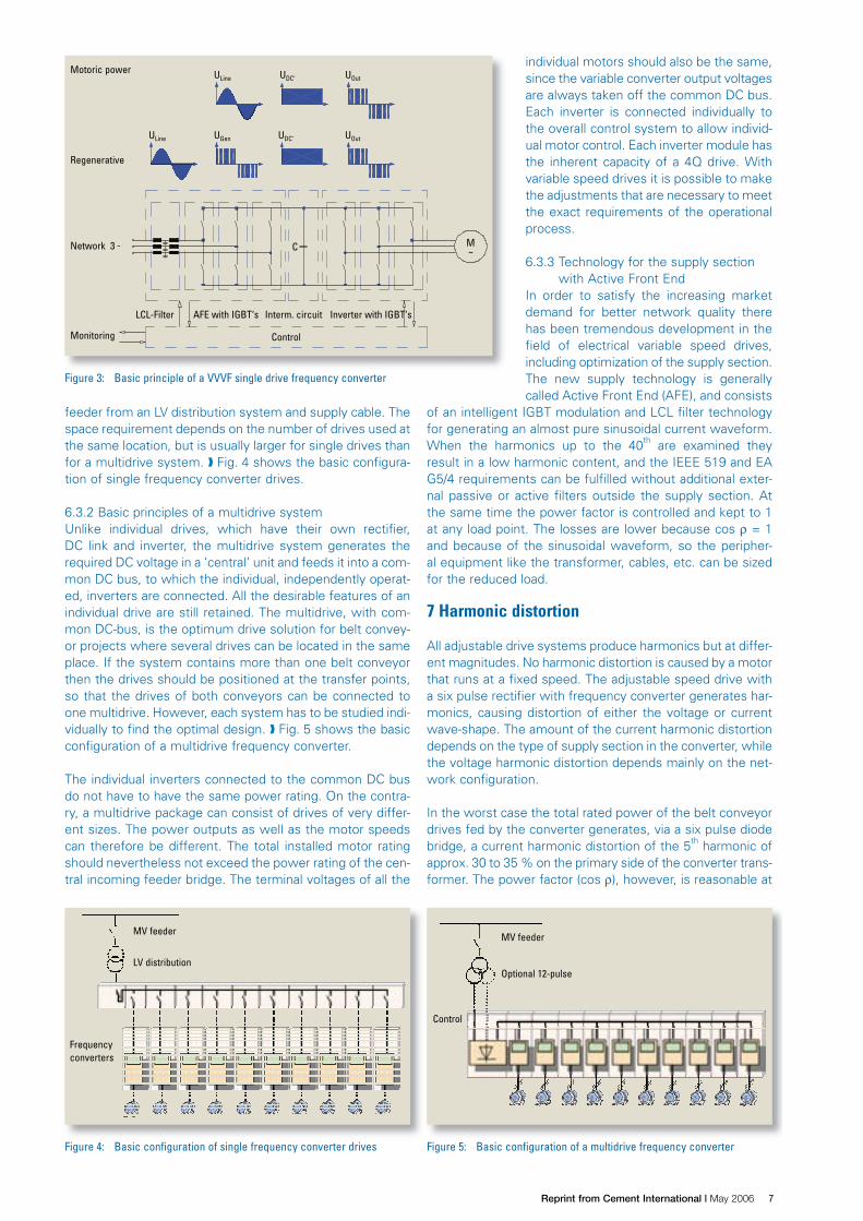
As was shown earlier, there are very good reasons for con-trolling the belt conveyors by variable speed drives. The fre-quency converters considered here are of the voltage-sourcetype. The system voltage is first rectified and then storedin a DC link, consisting mainly of capacitors. The inverter,with switchable semiconductor devices, subsequently con-verts the DC voltage back to AC to allow adjustment of itsfrequency and voltage. The speed of the connected cageinduction motor is then varied in accordance with the appliedfrequency. The voltage also has to be varied as a function ofthe frequency to ensure that the induced flux remains con-stant. Fig. 3 shows the basic principle of a VVVF singledrive frequency converter.
6.3. Variable speed drive solutions6.3.1 Basic principles of single drive configurationEvery individual frequency converter needs its own separate
Table 2: Technical parameters for both belt conveyors
Parameter Symbol UnitsBelt conveyor
tubetroug-
hed
Input
Capacity of the belt Qt t/h 1 400 1200
Frictional resistance of belt C – 0.6000 0.5200
Friction in pulleys 0.025 to 0.030 f – 0.0281 0.0250
Belt weight/m incl. rotating parts Gm kg/m 151 80
Distance between centres L m 244 2 397
Belt width (tube belt = diameter) B mm 400 1 200
Height H m -81 -193
Drum diameter D m 1.02 1.02
Belt speed v m/s 3.30 3.30
Gear ratio i – 25 25
Gear box efficiency η % 0.98 0.98
Output
Required motor shaft power atfull load
P kW -273 -449
Luechinger.indd 96 17.10.2006 9:33:50 Uhr
�Reprint from Cement International | May 2006 CEMENT INTERNATIONAL 4 5/2006 4 VOL. 4 97
PROC
ESSI
NG
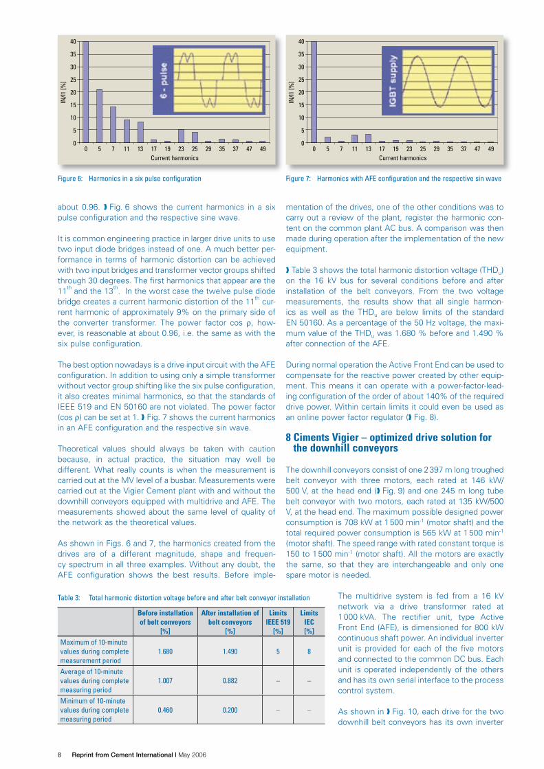
feeder from an LV distribution system and supply cable. Thespace requirement depends on the number of drives used atthe same location, but is usually larger for single drives thanfor a multidrive system. Fig. 4 shows the basic configura-tion of single frequency converter drives.
6.3.2 Basic principles of a multidrive systemUnlike individual drives, which have their own rectifier,DC link and inverter, the multidrive system generates therequired DC voltage in a ‘central’ unit and feeds it into a com-mon DC bus, to which the individual, independently operat-ed, inverters are connected. All the desirable features of anindividual drive are still retained. The multidrive, with com-mon DC-bus, is the optimum drive solution for belt convey-or projects where several drives can be located in the sameplace. If the system contains more than one belt conveyorthen the drives should be positioned at the transfer points,so that the drives of both conveyors can be connected toone multidrive. However, each system has to be studied indi-vidually to find the optimal design. Fig. 5 shows the basicconfiguration of a multidrive frequency converter.
The individual inverters connected to the common DC busdo not have to have the same power rating. On the contra-ry, a multidrive package can consist of drives of very differ-ent sizes. The power outputs as well as the motor speedscan therefore be different. The total installed motor ratingshould nevertheless not exceed the power rating of the cen-tral incoming feeder bridge. The terminal voltages of all the
individual motors should also be the same,since the variable converter output voltagesare always taken off the common DC bus.Each inverter is connected individually tothe overall control system to allow individ-ual motor control. Each inverter module hasthe inherent capacity of a 4Q drive. Withvariable speed drives it is possible to makethe adjustments that are necessary to meetthe exact requirements of the operationalprocess.
6.3.3 Technology for the supply sectionwith Active Front End
In order to satisfy the increasing marketdemand for better network quality therehas been tremendous development in thefield of electrical variable speed drives,including optimization of the supply section.The new supply technology is generallycalled Active Front End (AFE), and consists
of an intelligent IGBT modulation and LCL filter technologyfor generating an almost pure sinusoidal current waveform.When the harmonics up to the 40th are examined theyresult in a low harmonic content, and the IEEE 519 and EAG5/4 requirements can be fulfilled without additional exter-nal passive or active filters outside the supply section. Atthe same time the power factor is controlled and kept to 1at any load point. The losses are lower because cos ρ = 1and because of the sinusoidal waveform, so the peripher-al equipment like the transformer, cables, etc. can be sizedfor the reduced load.
7 Harmonic distortion
All adjustable drive systems produce harmonics but at differ-ent magnitudes. No harmonic distortion is caused by a motorthat runs at a fixed speed. The adjustable speed drive witha six pulse rectifier with frequency converter generates har-monics, causing distortion of either the voltage or currentwave-shape. The amount of the current harmonic distortiondepends on the type of supply section in the converter, whilethe voltage harmonic distortion depends mainly on the net-work configuration.
In the worst case the total rated power of the belt conveyordrives fed by the converter generates, via a six pulse diodebridge, a current harmonic distortion of the 5th harmonic ofapprox. 30 to 35 % on the primary side of the converter trans-former. The power factor (cos ρ), however, is reasonable at
Figure 3: Basic principle of a VVVF single drive frequency converter
Monitoring Control
LCL-Filter
Regenerative
ULine
C M
AFE with IGBT‘s Interm. circuit Inverter with IGBT‘s
Network 3
Motoric power UDC‘ UOut
ULine UGen UDC‘ UOut
Figure 4: Basic configuration of single frequency converter drives
Frequencyconverters
MV feeder
LV distribution
Figure 5: Basic configuration of a multidrive frequency converter
Control
MV feeder
Optional 12-pulse
Luechinger.indd 97 17.10.2006 9:33:51 Uhr
� Reprint from Cement International | May 2006 98 CEMENT INTERNATIONAL 4 5/2006 4 VOL. 4
PROC
ESSI
NG
about 0.96. Fig. 6 shows the current harmonics in a sixpulse configuration and the respective sine wave.
It is common engineering practice in larger drive units to usetwo input diode bridges instead of one. A much better per-formance in terms of harmonic distortion can be achievedwith two input bridges and transformer vector groups shiftedthrough 30 degrees. The first harmonics that appear are the11th and the 13th. In the worst case the twelve pulse diodebridge creates a current harmonic distortion of the 11th cur-rent harmonic of approximately 9% on the primary side ofthe converter transformer. The power factor cos ρ, how-ever, is reasonable at about 0.96, i.e. the same as with thesix pulse configuration.
The best option nowadays is a drive input circuit with the AFEconfiguration. In addition to using only a simple transformerwithout vector group shifting like the six pulse configuration,it also creates minimal harmonics, so that the standards ofIEEE 519 and EN 50160 are not violated. The power factor(cos ρ) can be set at 1. Fig. 7 shows the current harmonicsin an AFE configuration and the respective sin wave.
Theoretical values should always be taken with cautionbecause, in actual practice, the situation may well bedifferent. What really counts is when the measurement iscarried out at the MV level of a busbar. Measurements werecarried out at the Vigier Cement plant with and without thedownhill conveyors equipped with multidrive and AFE. Themeasurements showed about the same level of quality ofthe network as the theoretical values.
As shown in Figs. 6 and 7, the harmonics created from thedrives are of a different magnitude, shape and frequen-cy spectrum in all three examples. Without any doubt, theAFE configuration shows the best results. Before imple-
mentation of the drives, one of the other conditions was tocarry out a review of the plant, register the harmonic con-tent on the common plant AC bus. A comparison was thenmade during operation after the implementation of the newequipment.
Table 3 shows the total harmonic distortion voltage (THDu)on the 16 kV bus for several conditions before and afterinstallation of the belt conveyors. From the two voltagemeasurements, the results show that all single harmon-ics as well as the THDu are below limits of the standardEN 50160. As a percentage of the 50 Hz voltage, the maxi-mum value of the THDu was 1.680 % before and 1.490 %after connection of the AFE.
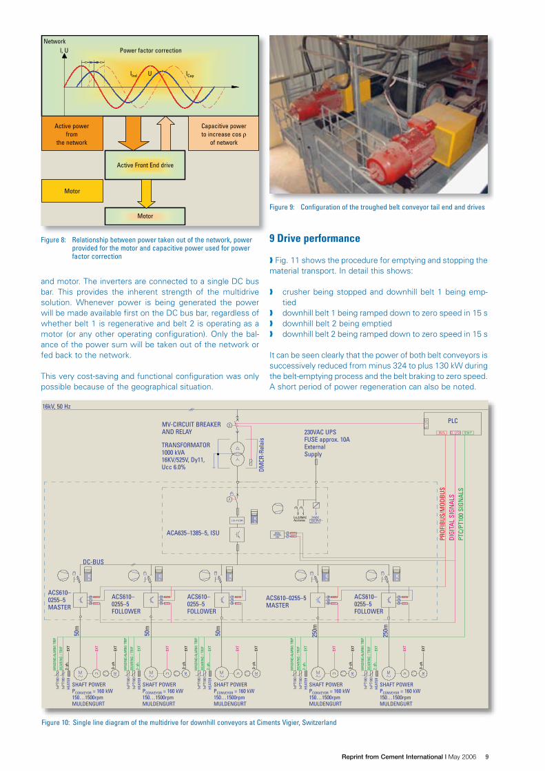
During normal operation the Active Front End can be used tocompensate for the reactive power created by other equip-ment. This means it can operate with a power-factor-lead-ing configuration of the order of about 140% of the requireddrive power. Within certain limits it could even be used asan online power factor regulator ( Fig. 8).
8 Ciments Vigier – optimized drive solution forthe downhill conveyors
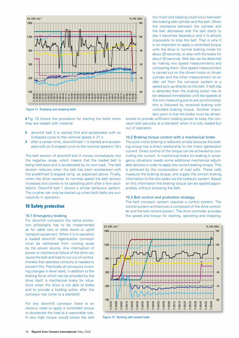
The downhill conveyors consist of one 2397 m long troughedbelt conveyor with three motors, each rated at 146 kW/500 V, at the head end ( Fig. 9) and one 245 m long tubebelt conveyor with two motors, each rated at 135 kW/500V, at the head end. The maximum possible designed powerconsumption is 708 kW at 1500 min-1 (motor shaft) and thetotal required power consumption is 565 kW at 1500 min-1
(motor shaft). The speed range with rated constant torque is150 to 1500 min-1 (motor shaft). All the motors are exactlythe same, so that they are interchangeable and only onespare motor is needed.
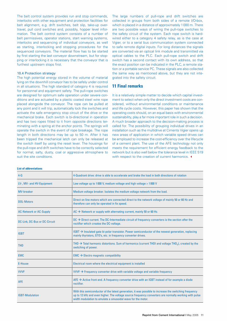
The multidrive system is fed from a 16 kVnetwork via a drive transformer rated at1000 kVA. The rectifier unit, type ActiveFront End (AFE), is dimensioned for 800 kWcontinuous shaft power. An individual inverterunit is provided for each of the five motorsand connected to the common DC bus. Eachunit is operated independently of the othersand has its own serial interface to the processcontrol system.
As shown in Fig. 10, each drive for the twodownhill belt conveyors has its own inverter
Table 3: Total harmonic distortion voltage before and after belt conveyor installation
Before installationof belt conveyors
[%]
After installation ofbelt conveyors
[%]
LimitsIEEE 519
[%]
LimitsIEC[%]
Maximum of 10-minutevalues during completemeasurement period
1.680 1.490 5 8
Average of 10-minutevalues during completemeasuring period
1.007 0.882 – –
Minimum of 10-minutevalues during completemeasuring period
0.460 0.200 – –
Figure 6: Harmonics in a six pulse configuration
40
35
30
25
20
15
10
5
00 5 7 11 13 17 19 23 25 29 35 37 47 49
Current harmonics
IN/l1
[%]
Figure 7: Harmonics with AFE configuration and the respective sin wave
40
35
30
25
20
15
10
5
00 5 7 11 13 17 19 23 25 29 35 37 47 49
Current harmonics
IN/l1
[%]
Luechinger.indd 98 17.10.2006 9:33:53 Uhr
�Reprint from Cement International | May 2006 CEMENT INTERNATIONAL 4 5/2006 4 VOL. 4 99
PROC
ESSI
NG
and motor. The inverters are connected to a single DC busbar. This provides the inherent strength of the multidrivesolution. Whenever power is being generated the powerwill be made available first on the DC bus bar, regardless ofwhether belt 1 is regenerative and belt 2 is operating as amotor (or any other operating configuration). Only the bal-ance of the power sum will be taken out of the network orfed back to the network.
This very cost-saving and functional configuration was onlypossible because of the geographical situation.
Figure 8: Relationship between power taken out of the network, powerprovided for the motor and capacitive power used for powerfactor correction
Motor
NetworkPower factor correction
Active Front End drive
Active powerfrom
the network
Motor
Capacitive powerto increase cos ρ
of network
l, U
lInd U lCap
Figure 9: Configuration of the troughed belt conveyor tail end and drives
9 Drive performance
Fig. 11 shows the procedure for emptying and stopping thematerial transport. In detail this shows:
crusher being stopped and downhill belt 1 being emp-tied
downhill belt 1 being ramped down to zero speed in 15 s downhill belt 2 being emptied downhill belt 2 being ramped down to zero speed in 15 s
It can be seen clearly that the power of both belt conveyors issuccessively reduced from minus 324 to plus 130 kW duringthe belt-emptying process and the belt braking to zero speed.A short period of power regeneration can also be noted.
Figure 10: Single line diagram of the multidrive for downhill conveyors at Ciments Vigier, Switzerland
NPBA
24VD
C
24VD
C
NPBA
M~
230V
>>T
EXT.
M
~ ~~M
NTAC
24VD
C
NPBA
24VD
C
NTAC
24VD
C
3x50
0V 230V
>>T
~M
EXT.
M
S
230V
>>T NTAC
24VD
C
3x50
0V
3x50
0V
EXT.
~MM
S
49
50G
51
50
27
V AAA M~
B
M~
NPBA
24VD
C
~M
~ ~
NTAC
24VD
C
NPBA
24VD
C23
0V
>>T
EXT.
M
M
>>T
230V
3x50
0V 24VD
C
~M
EXT.
M
NTAC
S
3x50
0V B
230 V / 50 Hz 230 V / 50 Hz 24 VDC
49 50 51 2750G
Emergency stopDisableStart/stopReset
Common faultReadyRunning
N-RefT-Limit
N-ActI-ActT-Act
Ext. emergency stopcat. 4, stop by ramp
Simatic S7by others
UPS (by others)
Converter trafo1 000 KVA16 KV/50 HzUk = 6%3 x 500 V/50 Hz
Supply 16 KV, 50 Hz
by others
by others
1x
secu
ndar
yw
indi
ngm
ax.t
emp.
alar
m/tr
ipBu
chho
lzpr
otec
tion
UndervoltageThermal protectionInst. overcurrentGround over currentA.C. time overcurrent
Cable length max. 50 m Prof
ibus
Supply section(ISU)ACA 635-1385-5
5 drivesectionACA 610-0325-5
Motor cablelength50 m
Common DC-Bus
Master-slave
Motor cablelength250 m
Master-slave
Master-slave
Down hill conveyor 2 Down hill conveyor 1
Luechinger.indd 99 17.10.2006 9:33:54 Uhr
Figure 10: Single line diagram of the multidrive for downhill conveyors at Ciments Vigier, Switzerland
16kV, 50 Hz
MV-CIRCUIT BREAKERAND RELAY
TRANSFORMATOR1000 kVA16KV/525V, Dy11,Ucc 6.0% D
MCR
-Rel
ais
230VAC UPSFUSE approx. 10AExternalSupply
PLC
ACA635–1385–5, ISU
PRO
FIB
US/
MO
DB
US
DIG
ITA
L SI
GN
ALS
PTC/
PT10
0 SI
GN
ALS
DC-BUS
ACS610–0255–5MASTER
ACS610–0255–5FOLLOWER
ACS610–0255–5FOLLOWER
ACS610–0255–5MASTER
ACS610–0255–5FOLLOWER
50m
50m
250m
50m
250m
WIN
DIN
G AL
ARM
/ TR
IP
BEA
RIN
G /
TRIP
1xPT
100
1xPT
100
HEA
TER
2–ph
.EX
T
EXT
3–ph
.
EXT
SHAFT POWERPCONVEYOR = 160 kW150…1500rpmMULDENGURT
WIN
DIN
G AL
ARM
/ TR
IP
BEA
RIN
G /
TRIP
1xPT
100
1xPT
100
HEA
TER
2–ph
.EX
T
SHAFT POWERPCONVEYOR = 160 kW150…1500rpmMULDENGURT
EXT
3–ph
.
EXT
WIN
DIN
G AL
ARM
/ TR
IP
BEA
RIN
G /
TRIP
1xPT
100
1xPT
100
HEA
TER
2–ph
.EX
T
SHAFT POWERPCONVEYOR = 160 kW150…1500rpmMULDENGURT
EXT
3–ph
.
EXT
WIN
DIN
G AL
ARM
/ TR
IP
BEA
RIN
G /
TRIP
1xPT
100
1xPT
100
HEA
TER
2–ph
.EX
T
SHAFT POWERPCONVEYOR = 160 kW150…1500rpmMULDENGURT
EXT
3–ph
.
EXT
WIN
DIN
G AL
ARM
/ TR
IP
BEA
RIN
G /
TRIP
1xPT
100
1xPT
100
HEA
TER
2–ph
.EX
T
SHAFT POWERPCONVEYOR = 160 kW150…1500rpmMULDENGURT
EXT
3–ph
.
EXT
10 Reprint from Cement International | May 2006 100 CEMENT INTERNATIONAL 4 5/2006 4 VOL. 4
PROC
ESSI
NG
Figure 11: Emptying and stopping belts
1 800
1 300
800
300
-200
-700
190
140
90
40
-10
-60
11:3
6:00
11:3
6:28
11:3
6:56
11:3
7:25
11:3
7:53
11:3
8:22
11:3
8:50
11:3
9:19
11:3
9:47
11:4
0:16
11:4
0:44
11:4
1:12
11:4
1:41
11:4
2:09
11:4
2:38
11:4
3:06
11:4
3:35
11:4
4:03
11:4
4:32
11:4
5:00
11:4
5:28
11:4
5:57
11:4
6:25
11:4
6:54
11:4
7:22
11:4
7:50
11:4
8:19
11:4
8:47
11:4
9:16
11:4
9:44
11:5
0:13
11:5
0:41
11:5
1:09
11:5
1:38
11:5
2:06
11:5
2:35
t/h; kW; min-1 %; kN; kNm
Figure 12: Starting with loaded belts
1 800
1 300
800
300
-200
-700
190
140
90
40
-10
-60
11:0
3:53
11:0
4:00
11:0
4:07
11:0
4:13
11:0
4:20
11:0
4:26
11:0
4:33
11:0
4:39
11:0
4:46
11:0
4:53
11:0
4:59
11:0
5:06
11:0
5:12
11:0
5:19
11:0
5:25
11:0
5:32
11:0
5:38
11:0
5:45
11:0
5:52
11:0
5:58
t/h; kW; min-1 %; kN; kNm
Fig. 12 shows the procedure for starting the belts whenthey are loaded with material:
downhill belt 2 is started first and accelerated with anS-shaped curve to the nominal speed in 21 s
after a certain time, downhill belt 1 is started and acceler-ated with an S-shaped curve to the nominal speed in 18 s
The belt tension of downhill belt 2 moves immediately intothe negative range, which means that the loaded belt isbeing held back and is accelerated by its own load., The belttension reduces when the belt has been accelerated withthe predefined S-shaped ramp, as explained above. Finally,when the drive reaches its nominal speed the belt tensionincreases and comes to its operating point after a few oscil-lations. Downhill belt 1 shows a similar behaviour pattern.The crusher can only be started up when both belts are suc-cessfully in operation.
10 Safety protection
10.1 Emergency brakingFor downhill conveyors the same protec-tion philosophy has to be implementedas for cable cars or other down or uphilltransport equipment. When it is in operationa loaded downhill regenerative conveyormust be restrained from running awayby the power source. Any interruption ofpower or mechanical failure of the drive cancause the belt and load to run out of control.A brake that operates correctly is needed toprevent this. Practically all conveyors involv-ing changes in level need, in addition to thebraking force which can be provided by thedrive itself, a mechanical brake for situa-tions when the drive is not able to brakeand to provide a holding action after theconveyor has come to a standstill.
For any downhill conveyor there is anobvious need to apply a controlled torqueto decelerate the load at a reasonable rate.A very high torque would stress the belt
too much and slipping could occur betweenthe braking belt cylinder and the belt. Whenthe resistance between the cylinder andthe belt decreases and the belt starts toslip it becomes hazardous and it is almostimpossible to stop the belt. That is why itis so important to apply a controlled torquewith the drive in normal braking mode forabout 20 seconds, or else with the brake forabout 20 seconds. Belt slip can be detectedby making two speed measurements andcomparing them. One speed measurementis carried out on the driven motor or drivencylinder and the other measurement on anidler roll from the conveyor system or aspeed pick-up directly on the belt. If belt slipis detected then the braking action has tobe released immediately until the speeds atthe two measuring points are synchronized;this is followed by renewed braking withcontrolled braking torque. Another impor-tant point is that the brake must be dimen-
sioned to provide sufficient holding power to keep the con-veyor belt securely at a standstill when it is fully loaded butout of operation.
10.2 Braking torque control with a mechanical brakeThe pure motor braking is relatively simple because the brak-ing torque has a direct relationship to the motor (generator)current. Direct control of the torque can be achieved by con-trolling the current. A mechanical brake for braking in emer-gency situations needs some additional mechanical adjust-able devices in order to apply the correct braking torque. Thisis achieved by the incorporation of load cells. These cellsmeasure the braking torque, and supply the correct brakinginformation to the disc brake via the hydraulic system. Basedon this information the braking torque can be applied appro-priately without stressing the belt.
10.3 Belt control and protection strategyThe belt conveyor system requires a control system. Thecontrol system architecture is composed of the drive control-ler and the belt control system. The drive controller providesthe speed and torque for starting, operating and stopping.
Luechinger.indd 100 17.10.2006 9:33:58 Uhr
11Reprint from Cement International | May 2006 CEMENT INTERNATIONAL 4 5/2006 4 VOL. 4 101
PROC
ESSI
NG
The belt control system provides run and stop commands,interlocks with other equipment and protection facilities forbelt alignment, e.g. drift switches, belt slip, take-up over-travel, pull cord switches and, possibly, hopper level infor-mation. The belt control system consists of a number ofbelt permissives, operator stations, start warning systems,interlocks and sequencing of individual conveyors, as wellas starting, interlocking and stopping procedures for thesequenced conveyors. The material flow has to be startedby first starting the last conveyor downstream, but for stop-ping or interlocking it is necessary that the conveyor that isfurthest upstream stops first.
10.4 Protection strategyThe high potential energy stored in the volume of materiallying on the downhill conveyor has to be safely under controlin all situations. The high standard of category 4 is requiredfor personnel and equipment safety. The pull-rope switchesare designed for optimum safe operation under severe con-ditions and are actuated by a plastic coated steel wire ropeplaced alongside the conveyor. The rope can be pulled atany point and it will trip, automatically lock the switches andactivate the safe emergency stop circuit of the drive or themechanical brake. Each switch is bi-directional in operationand has two ropes fitted to it from opposite directions ter-minating with a spring at the anchor points. The springs willoperate the switch in the event of rope breakage. The ropelength in both directions may be up to 50 m. After it hasbeen tripped the mechanical latch can only be released atthe switch itself by using the reset lever. The housings forthe pull-rope and drift switches have to be correctly selectedfor normal, salty, dusty, coal or aggressive atmosphere tosuit the site conditions.
The large numbers of pull-rope and drift switches arecollected in groups from both sides of a remote I/O-box,which is placed in a distance of approximately 1000 m. Thereare two possible ways of wiring the pull-rope switches tothe safety circuit of the system. Each rope switch is hard-wired either to a category 4 safety relay, as is the case atVigier, or to a serial bus communication system connectedto safe remote digital inputs. For long distances the signalsare converted via an optical link module and transmitted viaoptical cables to the PLC. Each pull-rope switch and driftswitch has a second contact with its own address, so thatthe exact position can be indicated in the PLC, a remote sta-tion or a portable service PC. These signals are also collectedthe same way as mentioned above, but they are not inte-grated into the safety circuit.
11 Final remarks
It is a relatively simple matter to decide which capital invest-ment to select when only the direct investment costs are con-sidered, without environmental conditions or maintenanceand life cycle costs. However, this paper has shown that theoperating costs should, on an equal basis with environmentalsustainability, play a far more important role in such a decision.A much broader approach to the decision-making process iscalled for. The possibility of grouping individual drives in aninstallation such as the multidrive at Ciments Vigier opens upnew areas of application in which variable speed drives canbe employed to increase the cost-efficiency over the lifecycleof a cement plant. The use of the AFE technology not onlymeets the requirement for efficient energy feedback to thenetwork but is also well below the tolerance level in IEEE 519with respect to the creation of current harmonics. 3
List of abbreviations
4-Q 4-Quadrant drive: drive is able to accelerate and brake the load in both directions of rotation
LV-, MV- and HV-Equipment Low voltage up to 1 000 V, medium voltage and high voltage > 1 000 V
MV-breaker Medium voltage breaker. Isolates the medium voltage network from the load.
DOL-MotorsDirect on line motors which are connected direct to the network voltage of mainly 50 or 60 Hz andtherefore can only be operated in fix speed.
AC-Network or AC-Supply AC ‡ Network or supply with alternating current, mainly 50 or 60 Hz.
DC-Link, DC-Bus or DC-CircuitDC ‡ Direct current. The DC-Intermediate circuit of frequency converters is the section after therectifier which creates the DC-voltage.
IGBTIGBT ‡ Insulated gate bi-polar transistor. Power semiconductor of the newest generation, replacingmainly thyristors, GTO’s, etc. in frequency converter drives.
THDTHD ‡ Total harmonic distortions. Sum of harmonics (current THDI and voltage THDU), created by theswitching of power.
EMC EMC ‡ Electro magnetic compatibility
E-House Electrical room where the electrical equipment is installed
VVVF VVVF ‡ Frequency converter drive with variable voltage and variable frequency
AFEAFE ‡ Active front end. A frequency converter drive with an IGBT instead of for example a dioderectifier.
IGBT-ModulationWith this semiconductor of the latest generation, it was possible to increase the switching frequencyup to 12 kHz and even higher. The voltage source frequency converters are normally working with pulsewidth modulation to emulate a sinusoidal wave for the motor.
Luechinger.indd 101 17.10.2006 9:33:59 Uhr


![3.3kV, 6.6kV屋内用避雷器...3.3kV 2500A 16kV 45kV 6.9kV以上 17kV以下 20kV以下 17kV以下 8.4kV 6.6kV 2500A 22kV 60kV 13.9kV以上 30kV以下[33kV以下] 33kV以下[38kV以下]](https://img.pdfslide.net/doc/110x75/5f0e954d7e708231d43ff074/33kv-66kvcee-33kv-2500a-16kv-45kv-69kv-17kv.jpg)