Embed Size (px)
Citation preview
5-30 GPM (19-114 L/min)
Fuel MeterModels:
M30-G6N, M30-L6N, M30-G8N, M30-L8N, M30-G8B, M30-L8B
Product Owner’s Manual EN
921529-01 Rev C04/2020
Please save these instructions for future reference. Read carefully before attempting to assemble, install, operate or maintain the product described.
Protect yourself and others by observing all safety information. Failure to comply with instructions could result in personal injury and/or property damage.
Please refer to back cover for information regarding this product’s warranty and other important information.
Thank you for choosing a Great Plains Industries product, and congratulations on your purchase!
Headquartered in the heartland of the U.S., GPI strives for integrity, innovation, continuous improvement, and dependability—values you will immediately recognize when using our products.
The maintenance policies and procedures outlined in this manual emphasize our commitment to safety and our dedication to you as a customer. By working together, we can ensure years of reliable, quality service.
SAVE FOR YOUR RECORDS
Model #: ___________________
Serial #: ___________________
Purch. Date: _______________
DO NOT RETURN THIS PRODUCT TO THE STORE!
Please contact Great Plains Industries, Inc. before returning any product. If you are missing parts, or experience problems with your installation, contact our Customer Support Department. We will be happy to assist you.
Call: 800-835-0113 or 316-686-7361
Email: [email protected]
SAFETY /
SPECIFIC
ATION
SA
SSEMB
LY / IN
STALLATIO
NO
PERATIO
NTR
OU
BLESH
OO
TING
MA
INTEN
AN
CE /
REPA
IRG
ETTING
STAR
TED
tools.eps
box.eps
magnify_2.eps
warning symbol.eps
measure.eps
plug.eps
oil.eps
megaphone.eps
biohaz.eps
Battery_Caution1.eps
Caution.eps
Crush_Caution1.eps
Electrical_Caution.eps
Face_protection.eps
Fall_Hazard.eps
Fall_protection.eps
GearHand_Hazard.eps
Head_protection.eps
Heavy_Hazard.eps
Hot_surface.eps
Recycle.eps
Resp_protection1.eps
Resp_protection2.eps
Temp_Caution1.eps
body_protection.eps
chemical_Caution.eps
ear_protection1.eps
explosive_caution.eps
eye_protection1.eps
foot_protection.eps
hand_protection.eps
BEFORE YOU BEGIN
Usage Requirements
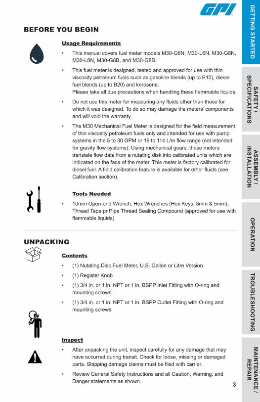
• This manual covers fuel meter models M30-G6N, M30-L6N, M30-G8N, M30-L8N, M30-G8B, and M30-G8B.
• This fuel meter is designed, tested and approved for use with thin viscosity petroleum fuels such as gasoline blends (up to E15), diesel fuel blends (up to B20) and kerosene. Please take all due precautions when handling these flammable liquids.
• Do not use this meter for measuring any fluids other than those for which it was designed. To do so may damage the meters’ components and will void the warranty.
• The M30 Mechanical Fuel Meter is designed for the field measurement of thin viscosity petroleum fuels only and intended for use with pump systems in the 5 to 30 GPM or 19 to 114 L/m flow range (not intended for gravity flow systems). Using mechanical gears, these meters translate flow data from a nutating disk into calibrated units which are indicated on the face of the meter. This meter is factory calibrated for diesel fuel. A field calibration feature is available for other fluids (see Calibration section).
Tools Needed
• 10mm Open-end Wrench, Hex Wrenches (Hex Keys, 3mm & 5mm), Thread Tape pr Pipe Thread Sealing Compound (approved for use with flammable liquids)
UNPACKING
Contents
• (1) Nutating Disc Fuel Meter, U.S. Gallon or Litre Version
• (1) Register Knob
• (1) 3/4 in. or 1 in. NPT or 1 in. BSPP Inlet Fitting with O-ring and mounting screws
• (1) 3/4 in. or 1 in. NPT or 1 in. BSPP Outlet Fitting with O-ring and mounting screws
Inspect
• After unpacking the unit, inspect carefully for any damage that may have occurred during transit. Check for loose, missing or damaged parts. Shipping damage claims must be filed with carrier.
• Review General Safety Instructions and all Caution, Warning, and Danger statements as shown. 3
4
MA
INTE
NA
NC
E /
REP
AIR
TRO
UB
LESH
OO
TIN
GO
PER
ATIO
NG
ETTI
NG
STA
RTE
DA
SSEM
BLY
/ IN
STA
LLAT
ION
SAFE
TY /
SPEC
IFIC
ATIO
NS
GENERAL SAFETY INSTRUCTIONSIMPORTANT: It is your responsibility to:
• Know and follow applicable national, state and local safety codes pertaining to installing and operating electrical equipment for use with flammable liquids.
• Know and follow all safety precautions when handling petroleum fuels.
• Ensure that all equipment operators have access to adequate instructions concerning safe operating and maintenance procedures.
Observe all safety precautions concerning safe handling of petroleum fuels.To prevent physical injury or property damage, observe precautions against fire or explosion when dispensing
fuel. Do not operate the meter in the presence of any source of ignition including running or hot engines, lighted tobacco products, gas or electric heaters, or any type of electronic device. A spark can ignite fuel vapors.
Avoid prolonged skin contact with petroleum fuels. Use protective goggles, gloves and aprons in case of
splashing or spills. Change saturated clothing and wash skin promptly with soap and water.
Any components such as hose, nozzle, or pump added to your meter must be statically grounded and approved for
use with petroleum fuels.
This product shall not be used for pumping fuel or other liquids into aircraft.
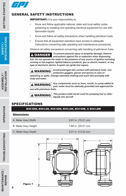
SPECIFICATIONSM30-G6N, M30-L6N, M30-G8N, M30-L8N, M30-G8B, & M30-L8Bf
Dimensions
A. Meter Assy Width 5.91 in. (15.01 cm)
B. Meter Assy Height 7.88 in. (20.01 cm)
C. Meter Assy Depth 5.21 in. (13.23 cm)
Figure 1
C
B
A

5
GETTIN
G STA
RTED
ASSEM
BLY /
INSTA
LLATION
OPER
ATION
TRO
UB
LESHO
OTIN
GM
AIN
TENA
NC
E / R
EPAIR
SAFETY /
SPECIFIC
ATION
S
SPECIFICATIONS (CONTINUED)M30-G6N, M30-G8N, & M30-
G8B (GALLON MODEL)M30-L6N, M30-L8N, &
M30-L8B (LITRE MODEL)
Unit of Measure U.S. Gallon Litre
Flow Range 5 to 30 GPM 19 to 114 L/min
Operating Temperature -20° F to 125° F -29° C to 52° C
Typical Accuracy ± 2%
Technology Nutating Disc
Housing, Cover, Fittings Aluminum
Maximum Working Pressure
50 PSIG / 3.4 bar
Pressure Drop (at Max. Flow)
Diesel: 7.0 PSI / 0.5 bar
Unleaded: 5.0 PSi / 0.3 bar
Inlet/Outlet Threads 3/4 in. NPT or 1 in. NPT or 1 in. BSPP
Maxium Batch Total 999.9
Maximum Cumulative Total
999,999.9
Weight 8.1 lbs 3.7 kg
Maximum Dimensions
Width: 5.9 in. 15.0 cm
Height: 7.9 in. 20.0 cm
Depth: 5.3 in 13.3 cm
Wetted Materials
Nutator Assembly PBT (Polybutylene Terephthalate), Stainless Steel
Seals NBR (Nitrile Butadiene Rubber)
Mag-Drive Acetal, Stainless Steel, Neodymium (Nickel Plated)
Approvals
NOTE: Accuracy is factory calibrated using diesel fuel. Field calibration is available on all models.
MA
INTE
NA
NC
E /
REP
AIR
TRO
UB
LESH
OO
TIN
GO
PER
ATIO
NG
ETTI
NG
STA
RTE
D
6
ASS
EMB
LY /
INST
ALL
ATIO
NSA
FETY
/ SP
ECIF
ICAT
ION
S
DECLARATION OF CONFORMITYWe declare, that the product:
Product Name: M30 Mechanical Fuel Meter
Model Numbers: M30-G*N, M30-L*N, M30-G*B, M30-L*B
Conforms with the requirements of the Directive (s) below by compliance with the Standards subsequently listed:
1. Council Directive 2014/34/EU relating to equipment and protective systems intended for use in potentially explosive atmospheres,
ISO 80079-36: 2016, Non-electrical equipment for explosive atmospheres- Basic methods and requirements.
ISO 80079-37:2016, Non -electrical equipment for explosive atmospheres-Non electrical type of protection constructional safety “c”.
I the undersigned, hereby declare that the equipment specified above conforms to the above Directive(s) and Standard(s).
Signature:
Full Name: Victor Lukic
Position: President
Great Plains Industries, Inc.
Place: Wichita, KS USA
January 2020
921529-11
7
GETTIN
G STA
RTED
OPER
ATION
TRO
UB
LESHO
OTIN
GM
AIN
TENA
NC
E / R
EPAIR
SAFETY /
SPECIFIC
ATION
SA
SSEMB
LY / IN
STALLATIO
N
INSTALLATION INSTRUCTIONSYour system must be installed on a vented tank. If the tank is unvented, your local dealer or distributor can
supply a pressure cap.If the meter is located in a rigid piping system where the fluid is trapped (for example, by gravity, valves or
nozzles) thermal expansion of the fluid can create pressure spikes that can damage a meter. Install a thermal relief valve or otherwise allow for thermal expansion of the fluid.
Before InstallingNOTE: All threaded fuel connections must be sealed with thread tape or a pipe thread sealing compound approved for use with petroleum fuels and tightened securely to prevent leakage.
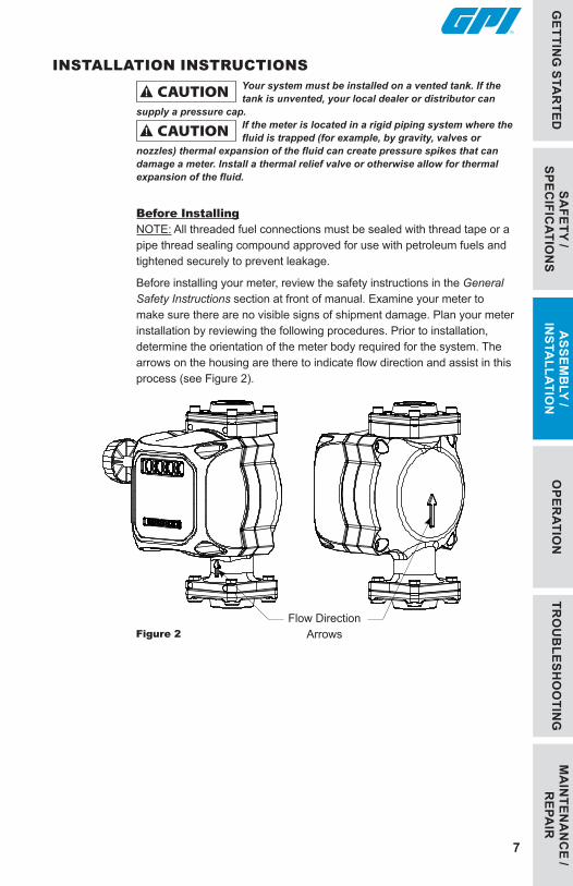
Before installing your meter, review the safety instructions in the General Safety Instructions section at front of manual. Examine your meter to make sure there are no visible signs of shipment damage. Plan your meter installation by reviewing the following procedures. Prior to installation, determine the orientation of the meter body required for the system. The arrows on the housing are there to indicate flow direction and assist in this process (see Figure 2).
Figure 2Flow Direction
Arrows

MA
INTE
NA
NC
E /
REP
AIR
TRO
UB
LESH
OO
TIN
GSA
FETY
/ SP
ECIF
ICAT
ION
SG
ETTI
NG
STA
RTE
D
8
OPE
RAT
ION
ASS
EMB
LY /
INST
ALL
ATIO
N
Change Register Orientation
NOTE: If the meter is plumbed in any orientation other than bottom-up flow, the register may need to be reoriented.
1. Using a 3mm L-hex wrench, remove the (4) screws that hold register in place
2. Rotate the register to the desired orientation, making sure the O-ring is fully seated (see Figure 3).
3. Reattach the register using the (4) screws previously removed (see Figure 3).
INSTALLATION INSTRUCTIONS (CONTINUED)
Figure 3
Figure 4a
O-ring
Position Lug (4)

9
GETTIN
G STA
RTED
SAFETY /
SPECIFIC
ATION
SO
PERATIO
NM
AIN
TENA
NC
E / R
EPAIR
TRO
UB
LESHO
OTIN
GA
SSEMB
LY / IN
STALLATIO
N
INSTALLATION INSTRUCTIONS (CONTINUED)
Figure 4a Figure 4b Figure 4c
Modular Connection Types
Installation Meter - Threaded Connection
1. Remove protective plugs from the meter inlet and outlet ports.
2. Wrap threaded male connections with thread tape or use a pipe sealant compound compatible with petroleum fuels.
3. Install the meter using appropriately sized fittings. “INLET” and “OUTLET” threads are labeled to assist piping connections.
4. Install other system components on the meter and tighten snugly.
Installation Meter - Modular Connection
1. Using a 5mm hex wrench and 10mm open-end wrench, remove inlet and outlet fitting. They will not be used in the modular connection (see Figure 4a).
2. Using 5mm hex wrench, remove the outlet of modular pump and reattach it to the outlet flange of the meter, making sure the O-ring is fully seated (see Figure 4b).
3. Using the hex bolts removed in step 1, attach meter inlet flange to pump outlet flange, making sure O-ring is fully seated (see Figure 4b.
NOTE: If modular filter adapter is also used in set-up, first attach filter adapter to pump outlet then attach the meter and filter to the filter adapter (see Figure 4c).
4. Install other system components on the meter and tighten snugly.
OutletFitting
IntletFitting
OutletFitting
Meter
FilterAdapter
Pump
Filter
MA
INTE
NA
NC
E /
REP
AIR
OPE
RAT
ION
ASS
EMB
LY /
INST
ALL
ATIO
NSA
FETY
/ SP
ECIF
ICAT
ION
SG
ETTI
NG
STA
RTE
D
10
TRO
UB
LESH
OO
TIN
G
OPERATION (CONTINUED)Always follow safety precautions when operating this equipment. Review the General Safety Instructions at
front of manual.
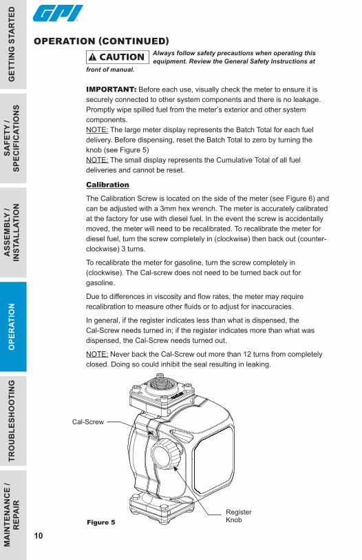
IMPORTANT: Before each use, visually check the meter to ensure it is securely connected to other system components and there is no leakage. Promptly wipe spilled fuel from the meter’s exterior and other system components.NOTE: The large meter display represents the Batch Total for each fuel delivery. Before dispensing, reset the Batch Total to zero by turning the knob (see Figure 5)NOTE: The small display represents the Cumulative Total of all fuel deliveries and cannot be reset.
Calibration
The Calibration Screw is located on the side of the meter (see Figure 6) and can be adjusted with a 3mm hex wrench. The meter is accurately calibrated at the factory for use with diesel fuel. In the event the screw is accidentally moved, the meter will need to be recalibrated. To recalibrate the meter for diesel fuel, turn the screw completely in (clockwise) then back out (counter-clockwise) 3 turns.
To recalibrate the meter for gasoline, turn the screw completely in (clockwise). The Cal-screw does not need to be turned back out for gasoline.
Due to differences in viscosity and flow rates, the meter may require recalibration to measure other fluids or to adjust for inaccuracies.
In general, if the register indicates less than what is dispensed, the Cal-Screw needs turned in; if the register indicates more than what was dispensed, the Cal-Screw needs turned out.
NOTE: Never back the Cal-Screw out more than 12 turns from completely closed. Doing so could inhibit the seal resulting in leaking.
Figure 5
Cal-Screw
Register Knob
11
GETTIN
G STA
RTED
SAFETY /
SPECIFIC
ATION
SA
SSEMB
LY / IN
STALLATIO
NO
PERATIO
N
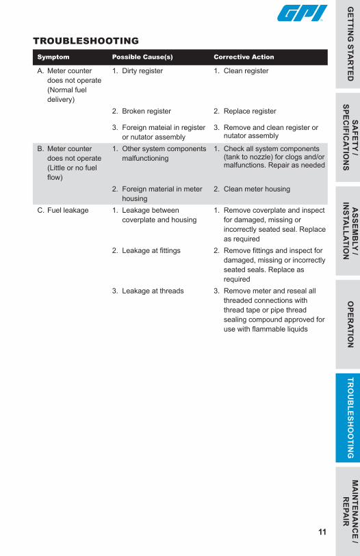
Symptom Possible Cause(s) Corrective Action
A. Meter counter does not operate (Normal fuel delivery)
1. Dirty register 1. Clean register
2. Broken register 2. Replace register
3. Foreign mateial in register or nutator assembly
3. Remove and clean register or nutator assembly
B. Meter counter does not operate (Little or no fuel flow)
1. Other system components malfunctioning
1. Check all system components (tank to nozzle) for clogs and/or malfunctions. Repair as needed
2. Foreign material in meter housing
2. Clean meter housing
C. Fuel leakage 1. Leakage between coverplate and housing
1. Remove coverplate and inspect for damaged, missing or incorrectly seated seal. Replace as required
2. Leakage at fittings 2. Remove fittings and inspect for damaged, missing or incorrectly seated seals. Replace as required
3. Leakage at threads 3. Remove meter and reseal all threaded connections with thread tape or pipe thread sealing compound approved for use with flammable liquids
TROUBLESHOOTING
MA
INTEN
AN
CE /
REPA
IRTR
OU
BLESH
OO
TING
TRO
UB
LESH
OO
TIN
GO
PER
ATIO
NA
SSEM
BLY
/ IN
STA
LLAT
ION
SAFE
TY /
SPEC
IFIC
ATIO
NS
GET
TIN
G S
TAR
TED
12
MAINTENANCENOTE: This meter is designed for minimum maintenance. Inspect meter and components regularly for fuel leaks. Keep the meter exterior clean to help identify leaks.
IMPORTANT: This fuel meter is designed, tested and approved for use with thin viscosity petroleum fuels such as gasoline blends (up to E15), diesel fuel blends (up to B20) and kerosene (see BEFORE YOU BEGIN: Usage Requirements at front of manual). Use of the meter with unauthorized fluids will void the warranty.
Clean Register and Nutator Assembly
1. Turn the system off and disconnect from power. Remove the coverplate and O-ring, and inspect for damage (see Figure 6). If O-ring is damaged, replace.
2. Remove (2) register screws and register from cover plate. Clean register with a soft-bristled brush and solvent. If the register is very dirty, compressed air may be used. Replace register.
3. Remove the gearplate and O-ring from the backshell, and inspect for damage (see Figure 6). If O-ring is damaged, replace.
4. Remove (2) nutator assembly screws and nutator assembly from back shell. Clean nutator assembly with a soft-bristled brush and solvent. If the nutator assembly is very dirty, compressed air may be used. Replace nutator assembly.
5. Coat the O-rings lightly with grease. Reinstall meter components. Ensure the O-rings are properly seated and tighten securely.
MA
INTE
NA
NC
E /
REP
AIR
13
GETTIN
G STA
RTED
SAFETY /
SPECIFIC
ATION
SA
SSEMB
LY / IN
STALLATIO
NO
PERATIO
NTR
OU
BLESH
OO
TING
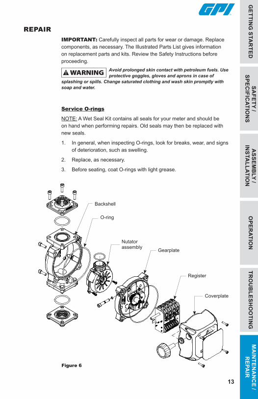
REPAIRIMPORTANT: Carefully inspect all parts for wear or damage. Replace components, as necessary. The Illustrated Parts List gives information on replacement parts and kits. Review the Safety Instructions before proceeding.
Avoid prolonged skin contact with petroleum fuels. Use protective goggles, gloves and aprons in case of
splashing or spills. Change saturated clothing and wash skin promptly with soap and water.
Service O-rings
NOTE: A Wet Seal Kit contains all seals for your meter and should be on hand when performing repairs. Old seals may then be replaced with new seals.
1. In general, when inspecting O-rings, look for breaks, wear, and signs of deterioration, such as swelling.
2. Replace, as necessary.
3. Before seating, coat O-rings with light grease.
MA
INTEN
AN
CE /
REPA
IR
Figure 6
������������������������
O-ring
Backshell
Nutator assembly
Coverplate
Register
Gearplate
14
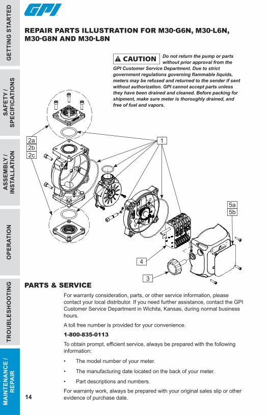
REPAIR PARTS ILLUSTRATION FOR M30-G6N, M30-L6N, M30-G8N AND M30-L8N
PARTS & SERVICEFor warranty consideration, parts, or other service information, please contact your local distributor. If you need further assistance, contact the GPI Customer Service Department in Wichita, Kansas, during normal business hours.
A toll free number is provided for your convenience.
1-800-835-0113
To obtain prompt, efficient service, always be prepared with the following information:
• The model number of your meter.
• The manufacturing date located on the back of your meter.
• Part descriptions and numbers.
For warranty work, always be prepared with your original sales slip or other evidence of purchase date.
Do not return the pump or parts without prior approval from the
GPI Customer Service Department. Due to strict government regulations governing flammable liquids, meters may be refused and returned to the sender if sent without authorization. GPI cannot accept parts unless they have been drained and cleaned. Before packing for shipment, make sure meter is thoroughly drained, and free of fuel and vapors.
TRO
UB
LESH
OO
TIN
GO
PER
ATIO
NA
SSEM
BLY
/ IN
STA
LLAT
ION
SAFE
TY /
SPEC
IFIC
ATIO
NS
GET
TIN
G S
TAR
TED
MA
INTE
NA
NC
E /
REP
AIR
������������������������
2a 1
4
3
5b
2b
5a
2c
15
GETTIN
G STA
RTED
SAFETY /
SPECIFIC
ATION
SA
SSEMB
LY / IN
STALLATIO
NO
PERATIO
NTR
OU
BLESH
OO
TING
MA
INTEN
AN
CE /
REPA
IR
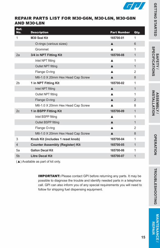
REPAIR PARTS LIST FOR M30-G6N, M30-L6N, M30-G8N AND M30-L8NRef.No.
Description
Part Number
Qty.
1 M30 Seal Kit 165700-01 1
O-rings (various sizes) ▲ 6
Grommet ▲ 1
2a 3/4 in NPT Fitting Kit 165700-08 1
Inlet NPT fitting ▲ 1
Outlet NPT fitting ▲ 1
Flange O-ring ▲ 2
M6-1.0 X 20mm Hex Head Cap Screw ▲ 8
2b 1 in NPT Fitting Kit 165700-02 1
Inlet NPT fitting ▲ 1
Outlet NPT fitting ▲ 1
Flange O-ring ▲ 2
M6-1.0 X 20mm Hex Head Cap Screw ▲ 8
2c 1 in BSPP Fitting Kit 165700-09 1
Inlet BSPP fitting ▲ 1
Outlet BSPP fitting ▲ 1
Flange O-ring ▲ 2
M6-1.0 X 20mm Hex Head Cap Screw ▲ 8
3 Knob Kit (includes 1 reset knob) 165700-04 1
4 Counter Assembly (Register) Kit 165700-05 1
5a Gallon Decal Kit 165700-06 1
5b Litre Decal Kit 165700-07 1
(▲) Available as part of kit only.
IMPORTANT: Please contact GPI before returning any parts. It may be possible to diagnose the trouble and identify needed parts in a telephone call. GPI can also inform you of any special requirements you will need to follow for shipping fuel dispensing equipment.
© 2020 Great Plains Industries, Inc., All Rights Reserved.Great Plains Industries, Inc. / 800-835-0113 / GPI.net
921529-01 Rev C04/2020
GPI® FOUR-YEAR LIMITED WARRANTY
Great Plains Industries, Inc. 5252 E. 36th Street North, Wichita, KS USA 67220-3205, hereby provides a limited warranty against defects in material and workmanship on all products manufactured by Great Plains Industries, Inc. This product includes a 4 year warranty from date of purchase as evidenced by the original sales receipt. A 54 month warranty from product date of manufacture will apply in cases where the original sales receipt is not available. Reference product labeling for the warranty expiration date based on 54 months from date of manufacture. Manufacturer’s sole obligation under the foregoing warranties will be limited to either, at manufacturer’s option, replacing or repairing defective goods (subject to limitations hereinafter provided) or refunding the purchase price for such goods theretofore paid by the buyer, and buyer’s exclusive remedy for breach of any such warranties will be enforcement of such obligations of manufacturer. The warranty shall extend to the purchaser of this product and to any person to whom such product is transferred during the warranty period. This warranty shall not apply if:
A. the product has been altered or modified outside the warrantor’s duly appointed representative;
B. the product has been subjected to neglect, misuse, abuse or damage or has been installed or operated other than in accordance with the manufacturer’s operating instructions.
To make a claim against this warranty, contact the GPI Customer Service Department at
316-686-7361 or 800-835-0113.Or by mail at:Great Plains Industries, Inc.5252 E. 36th St. NorthWichita, KS, USA 67220-3205
The company will guide you through a product troubleshooting process to determine appropriate corrective actions.GREAT PLAINS INDUSTRIES, INC., EXCLUDES LIABILITY UNDER THIS WARRANTY FOR DIRECT, INDIRECT, INCIDENTAL AND CONSEQUENTIAL DAMAGES INCURRED IN THE USE OR LOSS OF USE OF THE PRODUCT WARRANTED HEREUNDER.The company herewith expressly disclaims any warranty of merchantability or fitness for any particular purpose other than for which it was designed.This warranty gives you specific rights and you may also have other rights which vary from U.S. state to U.S. state.Note: In compliance with MAGNUSON-MOSS CONSUMER WARRANTY ACT – Part 702 (governs the resale availability of the warranty terms).


![IN-LINE ULTRASONIC FLOWMETER - Omega Engineering · Overload Flow Rate qs [GPM] 130 220350530 13208801585 Nominal Flow Rate qp [GPM] 65110 175 265440 1100660 ... Meter Body: Cast](https://img.pdfslide.net/doc/110x75/5c91f5ae09d3f26a458bae04/in-line-ultrasonic-flowmeter-omega-engineering-overload-flow-rate-qs-gpm.jpg)


![[GPM 083] Mi-14[1].GPM](https://img.pdfslide.net/doc/110x75/577d20571a28ab4e1e9298ca/gpm-083-mi-141gpm.jpg)