Embed Size (px)
Citation preview

5 CHAPTER 5

Published by the Range Safety OfficePatrick Air Force BaseFlorida 32925-3238

Chapter 5: Facilities and Structures Documentation, Design, Construction, Test, and Inspection Requirements 31 October 1997
CONTENTS
5-iii
Glossary of Abbreviations, Acronyms, and Definitions ......................................................................................... 5-v
Referenced Documents ..................................................................................................................................... 5-viii
5.1 INTRODUCTION........................................................................................................................................... 5-15.1.1 Purpose of the Chapter....................................................................................................................... 5-15.1.2 Applicability........................................................................................................................................ 5-1
5.2 RESPONSIBILITIES AND AUTHORITIES ..................................................................................................... 5-15.2.1 Systems Safety, 45th Space Wing and 30th Space Wing.................................................................... 5-15.2.2 Range Users ...................................................................................................................................... 5-25.2.3 Supporting Agencies .......................................................................................................................... 5-2
5.2.3.1 Civil Engineer Squadron, 45th Space Wing, and Civil Engineer Group, 30th Space Wing ........ 5-25.2.3.2 Fire Marshal, 45th Space Wing and 30th Space Wing ............................................................. 5-25.2.3.3 Bioenvironmental Engineering, 45th Space Wing and 30th Space Wing .................................. 5-25.2.3.4 Operations Safety ................................................................................................................... 5-3
5.3 FACILITIES AND STRUCTURES DESIGN AND CONSTRUCTION SITE POLICIES...................................... 5-35.3.1 Design, Construction, and Modification Policy..................................................................................... 5-35.3.2 Location Planning Requirements ........................................................................................................ 5-35.3.3 Construction Site Safety Policy........................................................................................................... 5-3
5.3.3.1 Compliance with Occupational Safety and Health Administration Regulations.......................... 5-35.3.3.2 Compliance with the United States Army Corps of Engineers Safety and Health Requirements Manual and Other Criteria .................................................... 5-3
5.4 DOCUMENTATION REQUIREMENTS .......................................................................................................... 5-45.4.1 Conventional and Critical Facility Determination ................................................................................. 5-45.4.2 Documentation Review and Approval Process .................................................................................... 5-45.4.3 Conventional Facilities and Structures Documentation Requirements ................................................. 5-4
5.4.3.1 Determining Criticality ............................................................................................................. 5-45.4.3.2 Conventional Facility Design Drawings and Specifications ....................................................... 5-45.4.3.3 Conventional Facility Demolition Plan...................................................................................... 5-4
5.4.4 Critical Facilities and Structures Documentation Requirements........................................................... 5-45.4.4.1 Critical Facility and Structure Design Criteria Document .......................................................... 5-45.4.4.2 Critical Facility and Structure Design Calculations ................................................................... 5-45.4.4.3 Hazard Analyses ..................................................................................................................... 5-45.4.4.4 Critical Facility and Structure Design Drawings and Specifications........................................... 5-55.4.4.5 Emergency and Critical Systems Design Drawings and Specifications..................................... 5-55.4.4.6 Test Plans and Test Reports ................................................................................................... 5-55.4.4.7 Critical Facility and Structure Demolition Plan ......................................................................... 5-55.4.4.8 Facility Safety Data Package................................................................................................... 5-5
5.5 CONVENTIONAL FACILITIES AND STRUCTURES ...................................................................................... 5-65.5.1 New, Rehabilitated, or Modified Conventional Facility and Structure Design Standards ....................... 5-65.5.2 Conventional Facility and Structure Elevators ..................................................................................... 5-65.5.3 Conventional Facility and Structure Life Safety Code Requirements.................................................... 5-6
5.5.3.1 Emergency Egress .................................................................................................................. 5-65.5.3.2 Emergency Lighting................................................................................................................. 5-6
5.5.4 Conventional Facility and Structure Electrical Equipment.................................................................... 5-65.5.5 Conventional Facility and Structure Personnel Anchorage and Anchorage Connectors........................ 5-65.5.6 WR Conventional Facility and Structure Seismic Design..................................................................... 5-75.5.7 Trailer Design..................................................................................................................................... 5-7
5.6 CRITICAL FACILITIES AND STRUCTURES.................................................................................................. 5-75.6.1 New, Rehabilitated, or Modified Critical Facilities and Structures General Design Requirements ......... 5-7
5.6.1.1 Critical Facility and Structure Design Standards ...................................................................... 5-75.6.1.2 Critical Facility and Structure Elevators ................................................................................... 5-75.6.1.3 Critical Facility and Structure Life Safety Code Requirements.................................................. 5-85.6.1.4 Critical Facility and Structure Structural Steel .......................................................................... 5-85.6.1.5 Critical Facility and Structure Design Load Criteria .................................................................. 5-85.6.1.6 Critical Facility and Structure Bonding and Grounding ............................................................. 5-95.6.1.7 Critical Facility and Structure Lightning Protection ................................................................... 5-95.6.1.8 Critical Facility and Structure Electrical Equipment .................................................................. 5-9
Eastern and Western Range 127-1 31 October 1997
CONTENTS
5-iv
5.6.1.9 Critical Facility and Structure Fencing.................................................................................... 5-115.6.1.10 Critical Facility and Structure Personnel Anchorage and Anchorage Connections................. 5-115.6.1.11 WR Critical Facility and Structure Seismic Design Requirements......................................... 5-12
5.6.2 Special Critical Facility Systems and Structures................................................................................ 5-125.6.2.1 Critical Facility and Structure Air Monitoring Systems ............................................................ 5-125.6.2.2 Guyed Towers....................................................................................................................... 5-135.6.2.3 Robot Systems...................................................................................................................... 5-135.6.2.4 Mobile Service Towers .......................................................................................................... 5-135.6.2.5 Hazardous Commodity Lockers............................................................................................. 5-135.6.2.6 Battery Storage and Processing Areas................................................................................... 5-13
5.6.3 Explosives Storage, Handling, and Processing Facilities................................................................... 5-135.6.3.1 Explosives Site Plans ............................................................................................................ 5-135.6.3.2 Explosives Storage, Handling, and Processing Facilities General Design Requirements......... 5-145.6.3.3 Explosives Facilities Area Warning Systems.......................................................................... 5-145.6.3.4 Hypergolic Propellant Main and Ready Storage Facilities....................................................... 5-155.6.3.5 Enclosed Hypergolic Propellant Processing Facilities............................................................. 5-17
5.7 FACILITY AND STRUCTURE EMERGENCY AND CRITICAL SYSTEMS TEST REQUIREMENTS............... 5-20
5.8 CRITICAL FACILITY AND STRUCTURE INITIAL INSPECTION REQUIREMENTS ..................................... 5-21
APPENDIX 5A: FACILITY SAFETY DATA PACKAGE........................................................................................ 5-22APPENDIX 5B: HAZARDOUS AREA CLASSIFICATION.................................................................................... 5-25
Chapter 5: Facilities and Structures Documentation, Design, Construction, Test, and Inspection Requirements 31 October 1997
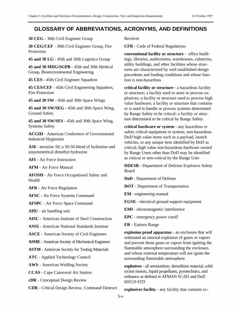
GLOSSARY OF ABBREVIATIONS, ACRONYMS, AND DEFINITIONS
5-v
30 CEG - 30th Civil Engineer Group
30 CEG/CEF - 30th Civil Engineer Group, FireProtection
45 and 30 LG - 45th and 30th Logistics Group
45 and 30 MDG/SGPB - 45th and 30th MedicalGroup, Bioenvironmental Engineering
45 CES - 45th Civil Engineer Squadron
45 CES/CEF - 45th Civil Engineering Squadron,Fire Protection
45 and 30 SW - 45th and 30th Space Wings
45 and 30 SW/SEG - 45th and 30th Space Wing,Ground Safety
45 and 30 SW/SES - 45th and 30th Space Wing,Systems Safety
ACGIH - American Conference of GovernmentalIndustrial Hygienists
A50 - aerozine 50; a 50-50 blend of hydrazine andunsymmetrical dimethyl hydrazine
AFI - Air Force Instruction
AFM - Air Force Manual
AFOSH - Air Force Occupational Safety andHealth
AFR - Air Force Regulation
AFSC - Air Force Systems Command
AFSPC - Air Force Space Command
AHU - air handling unit
AISC - American Institute of Steel Construction
ANSI - American National Standards Institute
ASCE - American Society of Civil Engineers
ASME - American Society of Mechanical Engineers
ASTM - American Society for Testing Materials
ATC - Applied Technology Council
AWS - American Welding Society
CCAS - Cape Canaveral Air Station
cDR - Conceptual Design Review
CDR - Critical Design Review, Command Destruct
Receiver
CFR - Code of Federal Regulations
conventional facility or structure - office build-ings, libraries, auditoriums, warehouses, cafeterias,utility buildings, and other facilities whose struc-tures are characterized by well established designprecedents and loading conditions and whose func-tion is non-hazardous
critical facility or structure - a hazardous facilityor structure; a facility used to store or process ex-plosives; a facility or structure used to process highvalue hardware; a facility or structure that containsor is used to handle or process systems determinedby Range Safety to be critical; a facility or struc-ture determined to be critical by Range Safety
critical hardware or system - any hazardous orsafety critical equipment or system; non-hazardousDoD high value items such as a payload, launchvehicles, or any unique item identified by DoD ascritical; high value non-hazardous hardware ownedby Range Users other than DoD may be identifiedas critical or non-critical by the Range User
DDESB - Department of Defense Explosive SafetyBoard
DoD - Department of Defense
DOT - Department of Transportation
EM - engineering manual
EGSE - electrical ground support equipment
EMI - electromagnetic interference
EPC - emergency power cutoff
ER - Eastern Range
explosion proof apparatus - an enclosure that willwithstand an internal explosion of gases or vaporsand prevent those gases or vapors from igniting theflammable atmosphere surrounding the enclosure,and whose external temperature will not ignite thesurrounding flammable atmosphere
explosives - all ammunition, demolition material, solidrocket motors, liquid propellants, pyrotechnics, andordnance as defined in AFMAN 91-201 and DoD6055.9-STD
explosives facility - any facility that contains ex-

Eastern and Western Range 127-1 31 October 1997
GLOSSARY OF ABBREVIATIONS, ACRONYMS, AND DEFINITIONS
5-vi
plosives or is quantity distance sited or licensed tocontain explosives
explosives quantity distance site plan - a formalplan required for explosive facilities and areas re-quired per AFM 91-201 and DoD-STD 6055.9detailing explosives quantity operating and storagelimits and restrictions, and resultant distance clear-ance requirements
FDR - Final Design Review
FM - Factory Mutual Corporation; frequencymodulation
FSDP - Facility Safety Data Package
ft - foot, feet
GN2 - gaseous nitrogen
h - hour, hours
hazardous facility or structure - a facility orstructure used to store, handle, or process hazard-ous materials or systems and/or perform hazardousoperations
hazardous materials - liquids, gases, or solids thatmay be toxic, reactive, or flammable or that maycause oxygen deficiency; either by themselves or incombination with other materials.
hazardous operations - those operations classifiedas hazardous according to the following criteria:(1) consideration of the potential or kinetic energyinvolved, (2) changes such as pressure, tempera-ture, and oxygen content in ambient environmentalconditions, (3) presence of hazardous materials.Hazardous operations include, but are not limitedto, the following types of operations: propellanttransport, transfer, handling and sampling; ord-nance transport, handling, checkout, installation,and connection; launch vehicle stages, payloads,and other critical loads hoists; pressure systemsoperating at pressures above 150 psig use andmaintenance; radioactive and toxic material stor-age, transport, and handling; confined space entryand cleaning; flight termination checkout (SeeChapter 4); radio frequency (RF) transmission;laser operations; cryogenic operations; energizedcircuit work. NOTE: Some low pressure systemsoperations such as those involving flight hardware,large volume systems, or those containing hazard-
ous commodities may be classified as hazardous byRange Safety.
hazard proof - a method of making electricalequipment safe for use in hazardous locations;these methods include explosion proofing, intrinsi-cally safe, purged and pressurized, and non-incendive and must be rated for the degree of haz-ard present
HVDS - Hypergolic Vapor Detection System
hydraulic - operating by water or other liquids un-der pressure
in. - inch, inches
intrinsically safe - incapable of producing suffi-cient energy to ignite an explosive atmosphere andtwo fault tolerant against failure with single faulttolerance against its most hazardous failure at 1.5times the maximum voltage or energy
IR - infrared
KSC - Kennedy Space Center
lb - pound, pounds
LEL - lower explosive limit
MIC - meets intent certification; a non-compliancedesignation used to indicate that an equivalent levelof safety is maintained despite not meeting the ex-act requirements stated in this document
MIL-HDBK - military handbook
MIL-SPEC - military specification
MIL-STD - military standard
MSPSP - Missile System Prelaunch Safety Pack-age; a data package demonstrating compliance withthe system safety requirements of Chapter 3, servesas a baseline for safety related information on thesystem throughout its life cycle
MMH - monomethyl hydrazine
N2H4 - hydrazine
NASA - National Aeronautics and Space Admini-stration
NEC - National Electrical Code
NFPA - National Fire Protection Association

Chapter 5: Facilities and Structures Documentation, Design, Construction, Test, and Inspection Requirements 31 October 1997
GLOSSARY OF ABBREVIATIONS, ACRONYMS, AND DEFINITIONS
5-vii
non-incendive - will not ignite group of gases orvapors for which it is rated; similar to “intrinsicallysafe,” but does not include failure tolerance ratings;used in rating electrical products for Class, Divi-sion 2 locations only
OSHA - Occupational Safety and Health Act
O&SHA - Operating and Support Hazard Analysis
PDB - Project Definition Book
PDR - Preliminary Design Review
PPE - Personal Protective Equipment
RAMP - Requirements Analysis Management Plan
RIDs - Review Item Discrepancies
safety critical facility - a hazardous facility or afacility that is used to store, handle, or processsystems determined to be safety critical by RangeSafety
SCAPE - Self-Contained Atmospheric ProtectiveEnsemble
SEAOC - Structural Engineers Association ofCalifornia
THC - Toxic Hazard Corridor
Toxic Hazard Corridor - a sector in which toxicmaterials may reach predetermined concentrationlevels
UDMH - Unsymmetrical Dimethyl Hydrazine
UEL - upper explosive limit
UL - Underwriters Laboratories
USAF - United States Air Force
UT - ultrasonic testing; umbilical tower of a launchpad
UV - ultraviolet
WR - Western Range
Eastern and Western Range 127-1 31 October 1997
REFERENCED DOCUMENTS
5-viii
29 CFR 1910, Occupational Safety and HealthStandards
29 CFR 1926, Safety and Health Regulations forConstruction
29 CFR 1910.23, Guarding Floor and WallOpenings and Holes
29 CFR 1910.106, Flammable and CombustibleLiquids
29 CFR 1926.104, Safety Belts, Lifelines, andLanyards
AFI 32-1065, Grounding Systems
AFI 32-2001, The Fire Protection Operations andFire Prevention Program
AFM 88, Air Force Civil Engineering SeriesManuals
AFM 88-3, Chapter 1, "Structural Design CriteriaLoads"
AFM 88-3, Chapter 13, “Seismic Design ForBuilding”
AFM 88-3, Chapter 14, "Design Criteria for Fa-cilities in Areas Subject to Typhoons and Hurri-canes"
AFM 88-9, Chapter 3, "Electrical Design, Light-ning, and Static Electricity Protection"
AFMAN 91-201, Explosives Safety Standards
AFOSH 91 and 127, Air Force OccupationalSafety and Health (Safety Series)
AFOSH 91-25, Confined Spaces
AFOSH 91-66, General Industrial Operations
AFOSH 127-43, Flammable and CombustibleLiquids
AFR 88-22, Structures to Resist the Effects of Ac-cidental Explosions
AISC, Manual of Steel Construction-AllowableStress Design
AISC Manual S337, Specification for AllowableStress Design of Simple Shear Connections
AISC Manual S329, High Strength Fasteners
ANSI/ASME A10.14, Construction and Demoli-
tion Operation-Requirements for Safety Belts,Harnesses, Lanyards, and Lifelines for Construc-tion and Demolition Use
ANSI/ASME A17.1, Safety Code for Elevatorsand Escalators
ANSI/ASME A17.2, Inspectors Manual for Ele-vators and Escalators
ANSI/ASME Z359.1, Safety Requirements forPersonnel Fall Arrest Systems, Subsystems, andComponents
ANSI/EIA/TIA 222, Structural Standards forSteel Antenna Towers and Antenna SupportingStructures
ANSI/RIA R15.06, Design, Installation, Testing,and Operation Requirements for Industrial Robotsand Robot Systems
ASCE 7-95, Minimum Design Loads for Buildingsand Other Structures
ASTM A36/A36M-96, Standard Specification forCarbon Structural Steel
ASTM A53-96, Standard Specification for Pipe,Steel, Black and Hot Dipped, Zinc-Coated, Weld-less and Seamless
ASTM A307-94, Standard Specification for Car-bon Steel Bolts and Studs, 60,000 psi TensileStrength
ASTM A325-96, Standard Specification forStructural Bolts, Steel, Heat Treated, 120/105 ksiMinimum Tensile Strength
ASTM A325 M-93, Standard Specification forHigh Strength Bolts for Structural Steel Joints(Metric)
ASTM A490-93, Standard Specification for HeatTreated Steel Structural Bolts, 150 ksi MinimumTensile Strength
ASTM A490M-93, Standard Specification forHigh-Strength-Strength Steel Bolts, Classes 10.9and 10.9.3 for Structural Steel Joints (Metric)
ASTM A500-93, Standard Specification for Cold-Formed Welded and Seamless Carbon Steel
Chapter 5: Facilities and Structures Documentation, Design, Construction, Test, and Inspection Requirements 31 October 1997
REFERENCED DOCUMENTS
5-ix
Structural Tubing in Rounds and Shapes
ASTM A501-93, Standard Specification for Hot-Formed Welded and Seamless Carbon SteelStructural Tubing
ASTM E1444, Magnetic Particle Inspection
ATC 3-06, Tentative Provisions for the Develop-ment of Seismic Regulations for Buildings, Na-tional Bureau of Standards
AWS D1.1, Structural Welding Code Steel
DoDI-4145.26, DoD Contractors’ Safety Re-quirements for Ammunition and Explosives
DoD 4145.26-M, DoD Contractors’ Safety Man-ual for Ammunition and Explosives
DoD 6055.9-STD, Ammunition and ExplosivesSafety Standards
EM 385-1-1, US Army Corps of Engineers Safetyand Health Requirements Manual
KSC-STD-C-0001, Recommendations for Protec-tive Coating Procedures and Materials for Exte-rior Structural Steel in Hypergolic Storage Fa-cilities
KSC-STD-E-0012, Standard for Bonding andGrounding
MIL-B-5087, Bonding, Electrical, and LightningProtection for Aerospace Systems
MIL-HDBK-419, Grounding, Bonding, andShielding for Electronic Equipment and Facilities
MIL-HDBK-1008, Fire Protection for FacilitiesEngineering, Design, and Construction
MIL-HDBK-1190, Facility Planning & DesignGuide
MIL-STD-188/124, Grounding, Bonding, andShielding for Electronic Equipment and Facilities
MIL-STD-410E, Non-Destructive ExaminationPersonnel Qualification and Certification
MIL-STD-810, Environmental Test Methods andEngineering Guidelines
MIL-STD-882, System Safety Program Require-ments
MIL-STD-1472, Human Engineering Design
Criteria for Military Systems, Equipment, and Fa-cilities
MIL-STD-1542, Electromagnetic Compatibilityand Grounding Requirements for Space SystemFacilities
MIL-STD-2154, Ultrasonic Inspection forWrought Metals
NEC Article 480, Storage Batteries
NEC Article 500, Hazardous (Classified) Loca-tions
NEC Section 500-3, Hazardous AtmosphericGroups
NEC Article 504, Intrinsically Safe Systems
NFPA 15, Water Spray Fixed Systems for FireProtection
NFPA 30 Flammable and Combustible LiquidsCode
NFPA 70, National Electric Code
NFPA 77, Static Electricity
NFPA 101, Life Safety Code
NFPA 780, Lightning Protection Systems
NFPA 496, Purges and Pressurized Enclosuresfor Electrical Equipment
NFPA 497, Recommended Standard Practice forClassification of Class 1 Hazardous Locations(Classified) for Electrical Installations in Chemi-cal Process Areas
SEAOC, Recommended Lateral Force Require-ments and Tentative Commentary
SNT-TC-1A, American Society for Non-Destructive Testing Standards
Society for Non-Destructive Testing Standards
Standard Building Code
Uniform Building Code
UL 913, Construction and Testing: IntrinsicallySafe Apparatus and Associated Apparatus

CHAPTER 5FACILITIES AND STRUCTURES DOCUMENTATION,
DESIGN, CONSTRUCTION, TEST, ANDINSPECTION REQUIREMENTS
5-1
5.1 INTRODUCTION
5.1.1 Purpose of the Chapter
Chapter 5 specifies minimum design, test, inspec-tion and data requirements for the construction andmodification of conventional and critical facilitiesand structures at the Eastern Range (ER) andWestern Range (WR). The following major topicsare addressed:
5.2 Responsibilities and Authorities5.3 Facilities and Structures Design and Con-
struction Site Policies5.4 Documentation Requirements5.5 Conventional Facilities and Structures5.6 Critical Facilities and Structures5.7 Facility and Structure Emergency and Criti-
cal Systems Test Requirements5.8 Critical Facilities and Structures Initial In-
spection Requirements
5.1.2 Applicability
All ER and WR facilities and structures are subjectto the requirements of this document regardless ofreal property accountability or ownership, includ-ing Department of Defense (DoD), National Aero-nautics and Space Administration (NASA), andcommercial users.
5.2 RESPONSIBILITIES AND AUTHORITIES
5.2.1 Systems Safety, 45th Space Wing and30th Space Wing
Any design standard having a reference to the"authority having jurisdiction" shall be interpretedto mean the 45th and 30th Space Wing, SystemsSafety (SES) with the exception of the NationalFire Protection Association (NFPA) standards, butnot NFPA 70, the National Electrical Code(NEC). NOTE: Unless otherwise noted, all refer-ences to Range Safety in this Chapter refer to 45SW/SES or 30 SW/SES. Range Safety is responsi-ble for the following:
a. Reviewing and approving the design, con-struction, modification, or demolition of all facili-ties and structures on the Ranges
b. Assisting Civil Engineering (45 CES and 30CEG), in preparing explosive quantity distance siteplans and for submitting them (with Civil Engi-neering assistance), to the Department of DefenseExplosive Safety Board (DDESB) through engi-neering and safety channels for review and ap-proval.
c. In conjunction with Civil Engineering (45 CESand 30 CEG), reviewing and approving facility orstructure modification or operational changes that

Eastern and Western Range 127-1 31 October 1997
5-2
affect explosive site plans or hazard level of thefacility
d. Approving the movement or relocation of ahazardous operation and/or system into a facility orstructure even if the facility or structure has beenused for similar operations in the past
e. In conjunction with Bioenvironmental Engi-neering (45 and 30 MDG/SGPB) and the Fire Mar-shal, (45 CES/CEF, 30 CEG/CEF) reviewing andapproving the performance characteristics of hy-pergolic propellant vapor control foam and deliverysystem design
f. In conjunction with Bioenvironmental Engi-neering (45 and 30 MDG/SGPB), reviewing andapproving the requirements for and design of airmonitoring systems
g. Performing surveillance and support of haz-ardous and safety critical operations as applicableto this Chapter. NOTE: Certain areas covered byAFI 31-101, Chapter 10, “Standard for DoD SpaceLift Operations Systems are exempted.
5.2.2 Range Users
Range Users are responsible for the following:
a. Ensuring that all facilities and structures undertheir jurisdiction are designed, constructed, modi-fied, and demolished in accordance with the provi-sions of this Chapter
b. Ensuring construction site safetyc. Coordinating with Bioenvironmental Engi-
neering (45 and 30 MDG/SGPB) in the design ofscrubbers and incinerators, hypergolic propellantvapor control foam and delivery systems, and airmonitoring systems
d. Coordinating with the Fire Marshal (45CES/CEF and 30 CEG/CEF) in the design of fireprotection systems and conduct of fire protectionactivities
e. Assisting in the preparation of explosive siteplans
5.2.3 Supporting Agencies
5.2.3.1 Civil Engineer Squadron, 45th SpaceWing, and Civil Engineer Group, 30th SpaceWing
The Civil Engineer Squadron, 45th Space Wing(45 CES) and the Civil Engineer Group, 30thSpace Wing (30 CEG) are responsible for the fol-lowing: NOTE: Unless otherwise noted, theseagencies will be referred to as Civil Engineering.
a. Preparing explosive site plans in coordinationwith the Range User and Range Safety, and assist-ing Range Safety to submit them to the DDESBthrough engineering and safety channels. NOTE:The DDESB is responsible for reviewing and ap-proving explosive site plans.
b. Obtaining permits for scrubbers and incinera-tors
c. In conjunction with Range Safety, reviewingand approving facility and structure modification oroperational changes that affect explosive site plans
5.2.3.2 Fire Marshal, 45th Space Wing and30th Space Wing
Any design standard in the NFPA standards withthe exception of NFPA 70, having a reference tothe "authority having jurisdiction" shall be inter-preted to mean the 45th or 30th Space Wing, FireMarshal (45 CES/CEF and 30 CEG/CEF).NOTE: Unless otherwise noted, these agencies willbe referred to as the Fire Marshal. The Fire Mar-shals are responsible for the following:
a. Providing necessary information to Civil En-gineering and Range Safety in regard to Range fa-cilities and structures fire protection requirements
b. Coordinating with Range Safety to ensure thatfacilities and structures on the Ranges meet na-tional fire protection standards
c. Reviewing and approving fire protection plansin accordance with AFI 32-2001
d. Conducting fire protection activities in accor-dance with MIL-HDBK-1008
e. In conjunction with Range Safety and Bioenvi-ronmental Engineering, reviewing and approvingthe performance characteristics of hypergolic pro-pellant vapor control foam and delivery systemsdesign
5.2.3.3 Bioenvironmental Engineering, 45thSpace Wing and 30th Space Wing
Bioenvironmental Engineering, 45th Space Wing(45 MDG/SGPB) and 30th Space Wing (30MDG/SGPB) are responsible for the following:NOTE: Unless otherwise noted, these agencies willbe referred to as Bioenvironmental Engineering.
a. Reviewing and approving the design ofscrubbers and incinerators
b. In conjunction with Range Safety and the FireMarshal (45 CES/CEF and 30 CES/CEF), review-
Chapter 5: Facilities and Structures Documentation, Design, Construction, Test, and Inspection Requirements 31 October 1997
5-3
ing and approving the performance characteristicsof hypergolic propellant vapor control foam anddelivery systems design
c. In conjunction with Range Safety, reviewingand approving the requirements for and design ofair monitoring systems
5.2.3.4 Operations Safety
The Range Support Contractor at the ER and the30th Space Wing Ground Safety Section (30SW/SEG) at the WR shall be referred to as Op-erations Safety. Operations Safety is responsiblefor inspecting new and modified facilities andstructures prior to initial startup operations in ac-cordance with AFMAN 91-201 and DoD 6055.9-STD.
5.3 FACILITIES AND STRUCTURESDESIGN AND CONSTRUCTION SITE
POLICIES
5.3.1 Design, Construction, and Modifica-tion Policy
All facilities and structures designed, constructed,and modified for use on the Ranges shall meet thestandards and provisions established in Chapters 3and 5 of this document and in other nationally rec-ognized codes and standards, including applicablestate regulations.
5.3.2 Location Planning Requirements
During the planning phase for construction ormodification of facilities, the following require-ments shall be taken into consideration:
a. The impact of the new facility operations toexisting and planned near-by facilities, base can-tonment areas, and off-base population centers aswell as the impact of existing and planned near-byfacilities on the new facility operations shall be ad-dressed.
b. Facilities shall not be located inside an exist-ing explosive safety clear zone unless the facility isrelated to the existing explosive-sited facility.
c. Overflight hazards shall be considered andcritical facilities should not be located immediatelydownrange of existing launch sites.
d. Location of facilities shall address operationalimpact from hypergolic transfer and storage opera-tion in near-by facilities.
e. Location of facilities that may contain hyper-golic commodities shall address Toxic Hazard Cor-ridors (THC) (see Chapter 6) and the potential im-pact on the general public and near-by facilities.
f. RF hazards shall be addressed.
5.3.3 Construction Site Safety Policy
With the exception of item d below, constructionsite safety shall be the sole responsibility of theRange User or contractor when the constructioncontract is issued by one of the following:
a. The United States Army Corps of Engineersb. A Range User or contractor where the ac-
countability of a 45/30 SW facility or work area istransferred to another Range User or contractor forconstruction and modification purposes
c. A United States Department of Transportation(DOT) commercial contractor or other non-UnitedStates Air Force (USAF) agencies, such as NASA,involved in construction activities on their own ac-countable facilities and launch complexes
d. All construction activities conducted within orin the vicinity of sites used to store or handle haz-ardous systems, high value equipment, or flighthardware shall be monitored by Range Safety withthe authority to impose a hold (stop work) whenunsafe conditions exist. However, the Range Useror contractor shall continue to have ultimate re-sponsibility for safety on the site.
5.3.3.1 Compliance with Occupational Safetyand Health Administration Regulations
Construction site activities on the Ranges shallcomply with Occupational Safety and Health Ad-ministration (OSHA) General Industry and Con-struction Standards (29 CFR 1910 and 1926).NOTE: Range Safety shall assume no liability forRange User or contractor compliance or noncom-pliance with OSHA requirements.
5.3.3.2 Compliance with the United StatesArmy Corps of Engineers Safety and HealthRequirements Manual and Other Criteria
Construction site activities on the Ranges should beperformed in accordance with EM 385-1-1 and thecriteria stated below. NOTE: Range Safety shallassume no liability for Range User or contractorcompliance or noncompliance with this documentor criteria.
Eastern and Western Range 127-1 31 October 1997
5-4
a. The construction contractor project superin-tendent or a designated representative should be atthe work site when work is being performed andshould serve as the single point of contact on allquestions concerning job site safety.
b. Safety violations should result in ContractAdministrator actions, including stopping work.
c. Accidents and injuries should be reported tothe Administrative Contracting Officer.
1. Serious mishaps should be reported as soonas possible.
2. The Administrative Contracting Officershould notify 45 or 30 SW/SEG, Ground Safety, ofserious accidents and injuries.
5.4 DOCUMENTATION REQUIREMENTS
5.4.1 Conventional and Critical Facility De-termination
All facilities, facility systems, and structures shallbe evaluated by the Range User to determine if theyare critical.
5.4.2 Documentation Review and ApprovalProcess
a. Unless otherwise agreed to by Range Safetyand the Range User or otherwise stated in thisChapter, the facility design engineering documentsdescribed in this section shall be submitted toRange Safety for review and approval 30 daysprior to the following design review meetings: in-troductory; conceptual (30 percent); Preliminary(60 percent); Critical (90 percent); and Final (100percent). NOTE 1: The introductory documenta-tion shall include, but is not limited to, such pre-liminary facility design documents as RequirementsAnalysis Management Plans (RAMPs) and ProjectDefinition Books (PDBs) NOTE 2: All facility de-sign engineering drawing and specification packagesshall have a space or block on the first drawing sheetreserved for the approval signature of the 45 SW/SESor 30 SW/SEG reviewing official. NOTE 3: All Re-view Item Discrepancies (RIDs) shall be addressedat each design review and resolved as soon as pos-sible.
b. Documentation requiring the review and ap-proval of Civil Engineering shall be submitted inaccordance with schedules jointly agreed upon bythe Range User and Civil Engineering.
c. Documentation requiring the review and ap-proval of Bioenvironmental Engineering shall be
submitted in accordance with schedules jointlyagreed upon by the Range User and Bioenviron-mental Engineering.
d. Documentation requiring the review and ap-proval of the Fire Marshal shall be submitted inaccordance with MIL-HDBK-1008.
5.4.3 Conventional Facilities and Struc-tures Documentation Requirements
5.4.3.1 Determining Criticality
Range Users shall submit documentation justifyingthe non-critical determination. This document-ationshall be submitted at the introductory and concep-tual (30 percent) design reviews.
5.4.3.2 Conventional Facility Design Drawingsand Specifications
Facility design engineering drawings and technicalspecification packages for conventional facilitiesshall be submitted.
5.4.3.3 Conventional Facility Demolition Plan
If applicable, a demolition plan shall be submit-ted.
5.4.4 Critical Facilities and StructuresDocumentation Requirements
5.4.4.1 Critical Facility and Structure DesignCriteria Document
a. Prior to facility and structure design, designcriteria that clearly state Range User requirementsand identify the essential features and functionsrequired in the facility shall be submitted.
b. The design criteria document shall be revisedperiodically to reflect the current status of designrequirements as they are developed.
5.4.4.2 Critical Facility and Structure DesignCalculations
a. The design of all structural steel buildings andother structures shall be based on documented, de-tailed, design calculations.
b. Seismic design analysis is required for WRfacilities, structures, and installed equipment.
c. Trailer anchoring analysis shall be submitted.d. The above design calculations and analyses
shall be submitted when completed.
5.4.4.3 Hazard Analyses
Hazard analyses of facilities, structures, and emer-gency and critical systems shall be conducted inaccordance with Appendix 1B, System Safety Pro-
Chapter 5: Facilities and Structures Documentation, Design, Construction, Test, and Inspection Requirements 31 October 1997
5-5
gram, as jointly tailored by Range Safety and theRange User.
5.4.4.4 Critical Facility and Structure DesignDrawings and Specifications
Facility and design engineering drawings and tech-nical specification packages for critical facilitiesshall be submitted.
5.4.4.5 Emergency and Critical Systems De-sign Drawings and Specifications
The following applicable emergency and critical sys-tems design drawings and specifications shall be sub-mitted for review and approval to Range Safety andother agencies as noted: NOTE: Design drawings andspecifications for other emergency and critical systemsnot identified below may be required by Range Safety.
a. Lightning protectionb. Bonding and groundingc. Robotsd. Emergency eyewash and showers (Bioen-
vironmental Engineering)e. Air monitoring systems (Bioenvironmental
Engineering)f. Area warning systemsg. Ventilation systemsh. Drain and sump systems (Civil Engineering
and Bioenvironmental Engineering)i. Scrubbers and incinerators (Civil Engineering
and Bioenvionmental Engineering)j. Liquid level indicatorsk. Conductive floorsl. Hazardous vapor detection systems (Bioen-
vironmental Engineering)m. Vapor control systemsn. Room purge systemso. Emergency Power Cutoff Systemsp. Emergency Monitor and Control Panelq. Personnel anchorage and anchorage con-
nectorsr. Elevatorss. Fire Protection System (Fire Marshal)
5.4.4.6 Test Plans and Test Reports
5.4.4.6.1 Test Plans.a. Test plans for the following applicable sys-
tems shall be submitted for review and approval toRange Safety and the other agencies noted 45 cal-endar days prior to the test: NOTE: Test plans forother systems may be required as identified byRange Safety.
1. Lightning protection in accordance withMIL-STD-1542
2. Bonding and grounding in accordance withMIL-STD-1542
3. Robots in accordance with ANSI/RIAR15.06
4. Emergency eyewash and showers (Bio-environmental Engineering)
5. Air monitoring systems (BioenvironmentalEngineering)
6. Area warning systems7. Ventilation systems8. Drain and sump systems (Civil Engineer-
ing and Bioenvironmental Engineering)9. Scrubbers/incinerators (Civil Engineering
and Bioenvironmental Engineering)10. Liquid level indicators11. Conductive floors12. Vapor control systems13. Hazardous vapor detection systems (Bio-
environmental Engineering)14. Room purge systems15. Technical Power Cutoffs16. Emergency Power Cutoff Systems17. Emergency Monitor and Control Panels18. Elevators in accordance with ASME/
ANSI A17.1 and A17.219. Integrated end-to-end test of interrelated
systems20. Personnel anchorage and anchorage con-
nectorsb. The test plan for the fire protection system
shall be submitted for review and approval to theFire Marshal 45 calendar days prior to the test.
5.4.4.6.2 Test Reports. Test reports shall besubmitted to Range Safety and the other agenciesnoted above for review and approval at least 45days prior to activation of the facility.
5.4.4.7 Critical Facility and Structure Demoli-tion Plan
If applicable, a demolition plan shall be submitted.
5.4.4.8 Facility Safety Data Package
A Facility Safety Data Package (FSDP) providingdetailed descriptions of the hazardous and criticalsystems in a facility or structure designated ascritical shall be provided. Content requirements arefound in Appendix 5A. As an alternate, a design
Eastern and Western Range 127-1 31 October 1997
5-6
package that contains all the elements specified inAppendix 5A is acceptable.
5.5 CONVENTIONAL FACILITIES ANDSTRUCTURES
5.5.1 New, Rehabilitated, or Modified Con-ventional Facility and Structure De-sign Standards
At a minimum, the design of new, rehabilitated, ormodified conventional facilities and structures onthe Ranges shall comply with or be equivalent tothe applicable standards of the current editions ofthe following documents:
a. MIL-HDBK-1190b. MIL-HDBK-1008c. Standard Building Code (ER only)d. Uniform Building Codee. 29 CFR 1910f. 29 CFR 1926g. AFOSH 127 Series and 91 Seriesh. AFM 88 Series Manualsi. ANSI/ASCE-7
5.5.2 Conventional Facility and StructureElevators
a. All elevators in conventional facilities andstructures shall be designed, built, and installed inaccordance with ASME/ANSI A17.1.
b. All elevators in conventional facilities andstructures shall be inspected, tested, and maintainedin accordance with ASME/ANSI A17.1. andASME/ANSI A17.2.
5.5.3 Conventional Facility and StructureLife Safety Code Requirements
The provisions of NFPA 101, the Life Safety Code,shall be incorporated in the design of each conven-tional facility and structure at the Ranges.
5.5.3.1 Emergency Egress
All emergency egress doors shall be equipped withpanic hardware and shall not be locked in a mannerthat would bar emergency egress.
5.5.3.2 Emergency Lighting
Emergency lighting shall be designed and installedin all locations such as windowless rooms and of-fices, stairways, and exit corridors from which per-sonnel egress would be hazardous in the event of apower failure.
5.5.4 Conventional Facility and StructureElectrical Equipment
At a minimum, electrical equipment and its instal-lation shall comply with the requirements of themost recent edition of the NEC (NFPA 70) or theregulations of OSHA, whichever are more restric-tive.
5.5.5 Conventional Facility and StructurePersonnel Anchorage and AnchorageConnectors
a. Consideration shall be given to the use of fixedplatforms in lieu of extensive use of personnel tie-offs.
b. If the design process determines that personneltie-offs are necessary, then fixed, permanently in-stalled anchorage connectors shall be used.
c. Personnel anchorage and anchorage connec-tors shall be designed and tested in accordance withANSI A10.14 and ANSI Z359.1.
d. Anchorage and anchorage connectors shall bedesigned to withstand a static load of 5000 lb perperson.
e. Design analysis shall consider all possiblevectors of forces induced by a fall.
f. Anchorage and anchorage connectors shall beload tested initially to 5000 lb static and shall notrequire re-testing except for causes such as corro-sion, damage, replacement, modification, repair, orexposure to launch heating.
g. Anchorage and anchorage connectors shall bestenciled or tagged with the maximum number ofpersons and/or total weight allowed to be attachedto the anchor at a given time using 5000 lb per per-son. NOTE: Such markings may be stenciled onthe surrounding structure.
h. Anchorage and anchorage connectors shall bestenciled or tagged with test weight and date.NOTE: Such markings may be stenciled on thesurrounding structure.
i. Anchorage and anchorage connectors shall belocated as close as possible to the work point aspractical.
j. Anchorage and anchorage connectors shall belocated as high as practical to limit the distance ofpotential fall.
k. Anchorage and anchorage connectors shall belocated so that an individual can attach to the con-nectors at waist height or above.
Chapter 5: Facilities and Structures Documentation, Design, Construction, Test, and Inspection Requirements 31 October 1997
5-7
l. Anchorage and anchorage connectors shall belocated so that they do not endanger fluid or gaslines, electrical cabling, critical hardware, or flightcomponents when the lifeline or lanyard is attached,in use, or under load. NOTE: To preclude theabove conditions, shielding or guarding of the com-ponents or system in question may be required.
m. Safety swivel hoist rings shall be the preferredanchorage connector rather than eye bolts.
5.5.6 WR Conventional Facility and Struc-ture Seismic Design
AFM 88-3, Chapter 13, places the WR in SeismicZone 4. NOTE: Local geologic structure deter-mines zone designation 1 through 4, considering thepotential severity, frequency, and damage from aseismic event. This designation means that the WRis located in the most severe seismic region. Theprobability of being exposed to a great earthquakeis large enough to require taking specific mitigatingmeasures in design.
a. Seismic design of all new or modified facili-ties, structures, installed equipment shall be in ac-cordance with AFM 88-3, Chapter 13 and SectionsA and B. Where specific design guidance is notprovided in these manuals, industry standards suchas those of the Seismology Committee StructuralEngineers Association of California (SEAOC),UBC, and Applied Technology Council (ATC 3-06) shall be used.
b. Seismic design shall consider both the verticaland horizontal component of seismic loading.
c. Facilities, structures, installed equipment, andtrailers that must remain operational after a seismicevent shall be designed in accordance with an im-portance factor of I of 1.5 in accordance with AFM88-3, Chapter 13.
d. Equipment installed in facilities needed forpost-earthquake recovery shall be designed to re-main operational after a seismic event.
e. Installed equipment that has the potential, di-rectly or by propagation, to cause the followingevents shall be restrained to restrict movement andwithstand a seismic event, but need not remain op-erational after a seismic event:
1. Severe personnel injury2. Catastrophic events3. Significant impact on space vehicle and/or
missile processing and launch capability. NOTE:
This criteria does not apply to commercial pro-grams.
5.5.7 Trailer Design
a. Trailers such as those used for offices, instru-mentation, shop, or storage, remaining in positionfor longer than 24 hours shall be anchored and sta-bilized.
b. Trailers shall be secured against wind loadsper the design criteria of AFM 88-3, Chapter 1 andANSI/ASCE-7.
5.6 CRITICAL FACILITIES ANDSTRUCTURES
5.6.1 New, Rehabilitated, or Modified Criti-cal Facilities and Structures GeneralDesign Requirements
5.6.1.1 Critical Facility and Structure DesignStandards
At a minimum, the design of new, rehabilitated, ormodified critical facilities and structures on theRanges shall comply with or be equivalent to theapplicable provisions of the current editions of thefollowing documents:
a. MIL-HDBK-1190b. MIL-HDBK-1008c. Standard Building Code (ER only)d. Uniform Building Codee. 29 CFR 1910f. 29 CFR 1926g. AFOSH 127 Series and 91 Seriesh. AFM 88 Series Manualsi. AFMAN 91-201 and DoD 6055.9-STDj. AFM 88-22k. MIL-STD-1472l. ANSI/ASCE-7
5.6.1.2 Critical Facility and Structure Elevators
a. All elevators in critical facilities on the Rangesshall be designed, built, and installed in accordancewith ASME/ANSI A17.1.
b. All elevators in critical facilities on the Rangesshall be inspected, tested, and maintained in accor-dance with ASME/ANSI A17.1. and ASME/ANSIA17.2.
c. All passenger elevators in critical facilitiesshall be built to the code requirements for generalpurpose elevators approved for freight elevators inaccordance with ASME/ANSI A17.1, Rule 207.l

Eastern and Western Range 127-1 31 October 1997
5-8
d. All freight elevators in critical facilities shallbe built to the code requirements for general pur-pose freight elevators approved for passengers inaccordance with ASME/ANSI A17.1, Rule 207.4.
e. All elevators in critical facilities shall beequipped with a public address (PA) speaker wherea PA system is available.
5.6.1.3 Critical Facility and Structure Life Safe-ty Code Requirements
The provisions of NFPA 101, the Life Safety Code,shall be incorporated in the design of all criticalfacilities and structures at the Ranges.
5.6.1.3.1 Emergency Egress.a. All side hinged doors that could be used as
a means of emergency egress from a high hazardfacility or structure shall be considered emergencyexits and shall swing in the direction of exit travel.
b. All emergency egress doors shall beequipped with panic hardware and shall not belocked in a manner that would bar emergencyegress.
5.6.1.3.2 Emergency Lighting. Emergencylighting shall be designed and installed in all loca-tions such as windowless rooms and offices, stair-ways, and exit corridors from which person-nelegress would be made hazardous in event of apower failure.
5.6.1.4 Critical Facility and Structure StructuralSteel
5.6.1.4.1 Critical Facility Structural Steel Gen-eral Design Requirements.
a. Critical structural steel facilities and struc-tures shall be designed in accordance with theAmerican Institute of Steel Constructions (AISC)“Manual of Steel Construction-Allowable StressDesign.”
b. Connections between structural membersshall be designed to use welded or bolted joints inaccordance with AISC M016 and S337.
5.6.1.4.2 Bolts and Fasteners.a. Permanent bolted structural joints shall use
high strength fasteners in accordance with AISCS329. EXCEPTION: ASTM A307 bolts may besubstituted for ASTM A325 and ASTM A490 fas-teners in those applications where stresses arevery low.
b. Joints using ASTM A307 and ASTM 325bolts in exterior applications shall use galvanized
fasteners. Joints using ASTM A490 heat treatedhigh strength bolts shall use plain fasteners that arecoated for corrosion protection.
c. ASTM A325 and ASTM A490 fastenersshall not be reused.
5.6.1.4.3 Welding.a. Welded connections shall use pre-qualified
welded joints in accordance with AISC M016,AISC S337, and AWS D1.1.
b. Welders, welding operators, and tackersshall be qualified in accordance with AWS D1.1.
c. All welds shall be inspected in accordancewith the following criteria:
1. 100 percent of all welds shall be visuallyinspected in accordance with AWS D1.1.
2. A random selection of 10 percent of allfillet welds shall be inspected using magnetic parti-cle testing techniques in accordance with ASTM-E1444 or the equivalent.
3. A random selection of 10 percent of allfull penetration welds shall be ultrasonically (UT)tested in accordance with MIL-STD-1699 or theequivalent.
(a) If rejectable discontinuities are found,then a second random 10 percent UT of these weldsshall be accomplished.
(b) If, on the second random 10 percent,UT rejectable discontinuities are uncovered, theremainder of the full penetration welds shall receivethe UT to determine the extent of the weld defects.
4. Nondestructive test personnel shall bequalified to SNT-TC-1A, Level 1 (under supervi-sion of a Level 2) or above.
5.6.1.4.4 Recommended Structural SteelMaterials.
a. ASTM A36 for plates and shapesb. ASTM A53 for pipec. ASTM A500 or ASTM A501 for structural
tubingd. Materials that are susceptible to stress cor-
rosion cracking shall be avoided.
5.6.1.5 Critical Facility and Structure DesignLoad Criteria
a. Design load assumptions for dead, live, andoperational wind loads shall be in accordance withAFM 88-3, Chapter 1.
b. Facilities and structures built in hurricane ar-eas shall be designed in accordance with AFM 88-3, Chapter 14 and/or American Society of Civil

Chapter 5: Facilities and Structures Documentation, Design, Construction, Test, and Inspection Requirements 31 October 1997
5-9
Engineers (ASCE) 7-95 or the most current edition.c. Unique loads such as equipment loads, impact
loads, launch environment loads (rocket engine ex-haust impingement, blast pressure, acoustics, orvibrations) shall be clearly defined and analyzed.
d. Minimum live loads for stairs, floor openingcovers, wall openings, handrails, fixed ladders, footwalks, and ramps shall be designed in accordancewith applicable sections of 29 CFR 1910 andASCE 7-95 or the most current edition.
e. As required, structural members shall be sizedto accept additional moments for the installation ofOSHA required personnel anchor points as de-scribed in 29 CFR 1926.502.
5.6.1.6 Critical Facility and Structure Bondingand Grounding
a. At a minimum, bonding and grounding re-quirements for all critical facilities and structuresshall comply with the requirements of ANSI/NFPA70. NOTE: The different types of facilities andstructures at the Ranges require varying degrees ofbonding and grounding beyond those specified byNFPA 70.
b. All facilities used to store, handle, or processordnance items or propellants shall be bonded andgrounded in accordance with AFMAN 91-201 andDoD 6055.9-STD.
c. Documents that may be used to designgrounding and bonding systems for the protectionof personnel and equipment from abnormal volt-ages are as follows:
1. MIL-STD-15422. MIL-B-50873. KSC-STD-E00124. MIL-STD-188/1245. AFMAN 91-201 and DoD 6055.9-STD,
Chapter 66. MIL-HDBK-4197. AFM 88-9, Chapter 38. ANSI/NFPA 77
5.6.1.7 Critical Facility and Structure LightningProtection
a. At a minimum, lightning protection require-ments for critical facilities and structures shallcomply with ANSI/NFPA 780.
b. Facilities and structures that require greaterprotection against direct or indirect lightning strikessuch as launch pads or explosives storage areas,shall also comply with the following:
1. AFM 88-9, Chapter 3, "Electrical Design,Lightning and Static Electricity Protection"
2. AFI 32-1065
Eastern and Western Range 127-1 31 October 1997
5-10
3. AFMAN 91-201 and DoD 6055.9-STD4. MIL-STD-1542
5.6.1.8 Critical Facility and Structure ElectricalEquipment
a. At a minimum, electrical equipment and itsinstallation in critical facilities and structures shallcomply with the requirements of the most recentedition of the NEC (NFPA 70) or the regulations ofthe OSHA, whichever are more restrictive.
b. Prior to being put into service, any electricalequipment that is not specifically labeled for thepurpose or conditions of operation intended by arecognized testing agency or that is not manufac-tured or installed to meet the electrical classifica-tion of the area in which the equipment is to be op-erated shall be approved by Range Safety.
5.6.1.8.1 Definition of Hazardous (Classified)Locations. Hazardous (classified) locations aredefined in Article 500 of the NEC; however, someexplosives and propellants are not covered. ForRange installations, the following paragraphs de-fine the minimum requirements to be applied in thedefinitions of locations in which explosives, pyro-technics, or propellants are or are expected to bepresent. These requirements shall be followed un-less less stringent classifications are justified andapproved as part of the design data submittal proc-ess. Range Safety and the Fire Marshal shall ap-prove all potential critical facility hazardous loca-tion designations. (See Appendix 5B for a flowpathfor classifying hazardous areas.)
a. Class 1, Division 11. Locations in which flammable liquids,
vapors, or gases may be present in air during nor-mal operations
2. Locations in which ignitable concentra-tions of such gases or vapors may exist frequentlybecause of repair or maintenance operations or be-cause of leakage
3. Locations in which the breakdown orfaulty operation of equipment or processes mightrelease ignitable concentrations of flammable gasesor vapors and might also cause simultaneous fail-ure of electrical equipment
4. As a baseline, these include the followinglocations:
(a) Within 25 ft of any vent opening unlessthe discharge is normally incinerated or scrubbed tononflammable conditions (less than 25 percent ofLower Explosive Limit (LEL)). This distance maybe increased if the vent flow rate creates a flamma-
bility concern at a distance greater than 25 ft.(b) Below grade locations in a Class 1, Divi-
sion 2 area.b. Class 1, Division 2
1. Locations in which volatile flammableliquids or flammable gases are handled, processedor used, but in which the liquids, vapors, or gaseswill normally be confined in closed containers orclosed systems from which they can escape only incase of accidental rupture or breakdown of suchcontainers or system or in case of abnormal opera-tion of equipment
2. Locations in which ignitable concentra-tions of gases or vapors are normally prevented bypositive mechanical ventilation and which mightbecome hazardous through failure or abnormal op-eration of ventilation equipment
3. Locations adjacent to a Class 1, Division1 location and to which ignitable concentrations ofgases or vapors might occasionally be communi-cated unless communication is prevented by ade-quate positive pressure ventilation from a source ofclean air, and effective safeguards against ventila-tion failure are provided. NOTE 1: This classifi-cation usually includes locations where volatileflammable liquids or flammable gases or vaporsare used but, in the judgment of Range Safety andthe Fire Marshal, would become hazardous only incase of an accident or of some unusual operatingcondition. The quantity of flammable material thatmight escape in case of an accident, the adequacyof ventilating equipment, the total area involved,and the record of the Range User with respect toexplosions or fires are all factors that merit consid-eration in determining the classification and extentof each location. NOTE 2: Piping without valves,checks, meters, and similar devices would not ordi-narily introduce a hazardous condition even thoughused for flammable liquids or gases. Locationsused for the storage of flammable liquids or of liq-uefied or compressed gases in sealed containerswould not normally be considered hazardous unlessalso subject to other hazardous conditions. NOTE3: As determined by Range Safety and the FireMarshal, locations may actively change classifica-tion depending upon the flammable fluid systemactivity and configuration. For these types of loca-tions, fixed or permanently installed electricalequipment shall be designed for the worst case haz-ardous environment. NOTE 4: Portable electricalequipment shall be designed for the worst case haz-ardous environment in which it will be used. Port-able equipment that is not designed for use in aparticular hazardous environment is not allowed in
Chapter 5: Facilities and Structures Documentation, Design, Construction, Test, and Inspection Requirements 31 October 1997
5-11
that environment or shall be locked out from use inthat environment.
4. As a baseline, Class 1, Division 2 loca-tions include the following equipment or areas:
(a) Storage vessels (including carts anddrums): 25 ft horizontally and below to grade and 4ft vertically above the vessel (25 ft in any directionfor hydrogen)
(b) Transfer lines: 25 ft horizontally andbelow to grade and 4 ft above the line (25 ft in anydirection for hydrogen)
(c) Launch vehicle (liquid fueled vehicle,stage, or payload): 100 ft radius horizontally fromand 25 ft vertically above (100 ft for hydrogen) thehighest leak or vent source and below the vehicle tograde
(d) Enclosed locations such as rooms, workbays, and launch complex clean rooms that areused to store and handle flammable and combusti-ble propellants when the concentration of vaporsinside the room resulting from a release of all fluidsstored and handled equals or exceeds the LEL.NOTE: The quantity of fluids used in the analysisshall be the maximum amount allowed in the explo-sives site plan.
c. Hazardous Commodity Groups. Hazard-ous commodities are grouped by similar character-istics. NOTE: These fuels shall be considered ig-nitable regardless of the ambient temperature. Thefollowing fuels shall be categorized as follows:
1. Group B: Liquid or gaseous hydrogen2. Group C: Hypergolic fuels such as N2H4,
MMH, UDMH, A503. Group D: Hydrocarbon fuels (RP and JP)4. Group D: Oxidizers. Oxidizers shall be
considered Group D hazardous substances in addi-tion to the fluids listed in Section 500-3 of theNEC.
d. Exposed Solid Propellants. The atmos-phere within 10 ft of exposed solid propellant shallbe classified as a Class 1, Division 2, Group Dlocation. Solid rocket motors are considered ex-posed in the following situations:
1. The motor nozzle is not attached and theaft end of the motor does not have a cover.
2. The motor nozzle is attached but does nothave a nozzle plug.
3. The unassembled motor segments do nothave front and rear covers.
4. The igniter is removed from the motor andcover is not provided.
5.6.1.8.2 Electrical Systems and EquipmentHazard Proofing. Electrical systems and equip-
ment used in hazardous locations shall be designedand listed for the locations in accordance with thefollowing requirements:
a. Explosion proof apparatus shall meet therequirements of the NEC for Class I, Division 1 or2, and be listed and labeled by a nationally recog-nized testing laboratory such as Underwriter's Lab-oratories (UL), Factory Mutual Corporation (FM).
b. Non-incendive apparatus shall meet the re-quirements of NEC Article 501, ANSI/ISA-S12.2,and are restricted to installation in Class I, Division2 locations only. They shall be listed and labeled bya nationally recognized testing laboratory such asUL or FM.
c. Intrinsically safe equipment intended for anyNEC Hazardous (Classified) location shall meet therequirements of NEC Article 504 and UL 913 andbe listed and labeled by a nationally recognizedtesting laboratory such as FM or UL.
d. The use of purged and pressurized electri-cal enclosures designed in accordance with NFPA496 for the purpose of eliminating or reducing thehazardous location classification as defined in Ar-ticle 500 of the NEC is acceptable with the fol-lowing additional requirements:
1. The purged and pressurized enclosureshall be maintained at a nominal 1/2 in. of waterunless a lower pressure is approved by RangeSafety. In no case shall the pressure in enclosuresbe less than 1/10 in. of water.
2. Rooms into which unprotected personnelmay enter shall be purged with air only.
3. Purged rooms and enclosures shall be pro-vided with an audible alarm set to trigger when thepressure drops below 1/4 in. water.
e. Equipment inspected and tested to othergovernment standards such as MIL-STD-810 maybe used if approved by Range Safety in coordina-tion with Civil Engineering.
f. Exterior Interconnecting Cable1. Exterior interconnecting cable installed in
the "open" is acceptable for interconnecting electri-cal equipment in a hazardous location. NOTE:Open refers to open trays or raceways that cannottrap gases when installing exterior type cable tointerconnect electrical equipment in a hazardouslocation.
2. Cable installation shall comply with therequirements of Article 504 of the NEC.
5.6.1.8.3 Backup Power Sources. Backup
Eastern and Western Range 127-1 31 October 1997
5-12
power sources shall be provided for critical loadrequirements when the loss of the normal powersource would cause injury and/or death to person-nel or loss of flight hardware.
5.6.1.9 Critical Facility and Structure Fencing
a. Fencing encompassing critical facilities shallhave emergency egress gates.
b. A sufficient number of gates shall be providedand located to preclude the necessity for personnelto egress toward or past any potential hazard.
c. If fencing can become electrically charged bylightning, falling electrical power lines, or compo-nent failure of adjacent electrical equipment, suchas substation transformers or switchgear, fencesshall be grounded and gates bonded.
5.6.1.10 Critical Facility and Structure Person-nel Anchorage and Anchorage Connections
a. Consideration shall be given to the use of fixedplatforms in lieu of extensive use of personnel tie-offs.
b. If the design process determines that personneltie-offs are necessary, then fixed permanently in-stalled anchorage connectors shall be used.
c. Personnel anchorage and anchorage connec-tors shall be designed and tested in accordance withANSI A10.14 and ANSI Z359.1.
d. Anchorage and anchorage connectors shall bedesigned to withstand a static load of 5000 lb perperson.
e. Design analysis shall consider all possiblevectors of forces induced by a fall.
f. Anchorage and anchorage connectors shall beload tested initially to 5000 lb static and shall notrequire retesting except for causes such as corro-sion, damage, replacement, modification, repair, orexposure to launch heating.
g. Anchorage and anchorage connectors shall bestenciled or tagged with the maximum number ofpersons and/or total weight allowed to be attachedto the anchor at a given time using 5000 lb per per-son. NOTE: Such markings may be stenciled onthe surrounding structure.
h. Anchorage and anchorage connectors shall bestenciled or tagged with test weight and date.NOTE: Such markings may be stenciled on thesurrounding structure.
i. Anchorage and anchorage connectors shall belocated as close as possible to the work point aspractical.
j. Anchorage and anchorage connectors shall belocated as high as practical to limit the distance ofpotential fall.
k. Anchorage and anchorage connectors shall belocated so that an individual can attach to the con-nector at waist height or above.
l. Anchorage and anchorage connectors shall belocated so that they do not endanger fluid or gaslines, electrical cabling, critical hardware, or flightcomponents when the lifeline or lanyard is attached,in use, or under load. NOTE: To preclude theabove conditions, shielding or guarding of the com-ponents or system in question may be required.
m. Safety swivel hoist rings shall be the preferredanchorage connector rather than eye bolts.
5.6.1.11 WR Critical Facility and StructureSeismic Design Requirements
AFM 88-3, Chapter 13, places the WR in SeismicZone 4. NOTE: Local geologic structure deter-mines zone designation 1 through 4, considering thepotential severity, frequency, and damage from aseismic event. This designation means that the WRis located in the most severe seismic region. Theprobability of being exposed to a great earthquakeis large enough to require taking specific mitigatingmeasures in design.
a. Seismic design of all new or modified facili-ties, structures, installed equipment shall be in ac-cordance with AFM 88-3, Chapter 13 and SectionsA and B. Where specific design guidance is notprovided in these manuals, industry standards suchas SEAOC, UBC, and ATC 3-06 shall be used.
b. Seismic design shall consider both the verticaland horizontal component of seismic loading.
c. Facilities, structures, installed equipment, andtrailers that must remain operational after a seismicevent shall be designed in accordance with an im-portance factor of 1 of 1.5 in accordance withAFM 88-3, Chapter 13.
d. Equipment installed in facilities needed forpost-earthquake recovery shall be designed to re-main operational after a seismic event.
e. Installed equipment that has the potential, di-rectly or by propagation, to cause the followingevents shall be restrained to restrict movement andwithstand a seismic event, but need not remain op-erational after a seismic event:
1. Severe personnel injury2. Catastrophic events3. Significant impact on space vehicle and/or
Chapter 5: Facilities and Structures Documentation, Design, Construction, Test, and Inspection Requirements 31 October 1997
5-13
missile processing and launch capability. NOTE:This criteria does not apply to commercial pro-grams.
4. Damage to high value flight hardware.NOTE: This criteria does not apply to commercialprograms.
5.6.2 Special Critical Facility Systems andStructures
The following requirements are for unique criticalfacility systems and structures. These requirementssupplement the general requirements in the New,Rehabilitated, or Modified Critical Facilities andStructures General Design Requirements sectionof this Chapter.
5.6.2.1 Critical Facility and Structure Air Moni-toring Systems
5.6.2.1.1 Critical Facility and Structure AirMonitoring System General Design Require-ments.
a. Locations in which there is a potential haz-ard of oxygen deficiency, toxicity, or flammabilitythat could result in personnel injury or death shallbe provided with air monitoring systems. Portablemonitoring units may be utilized prior to access inlieu of permanent systems with BioenvironmentalEngineering and Range Safety approval. NOTE:The following are examples of locations requiringair monitoring if personnel entry is required: (1)enclosed areas, rooms, and vehicle compartmentswhere pressurized inert gas systems are locatedand/or routed that could deplete or displace oxygen;(2) enclosed areas, rooms, and vehicle compart-ments where propellant systems are located and/orrouted; (3) storage tank entry points; (4) drain pits;and (5) tunnels.
b. Range Users, Bioenvironmental Engineer-ing, and Range Safety shall evaluate and identifylocations that require air monitoring systems.
c. AFOSH 91-25 and OSHA requirementsshall be complied with.
5.6.2.1.2 Air Monitoring Systems LocationsHaving Regular Access.
a. Continuous monitoring equipment with localand remote alarms and primary power and backupbattery power shall be installed in the hazardousarea.
b. The alarm shall be audible above ambientnoise levels and shall not be capable of being lo-cally silenced.
c. The remote alarm signal shall be transmittedto the blockhouse, operations control center, orRange Fire Station where 24 hr continuous moni-toring is provided.
d. Alarms at local and remote locations shallhave visual and audible signals.
5.6.2.1.3 Air Monitoring System LocationsHaving Infrequent or Temporary Access.
a. Local warning indicators including signs andportable flashers shall be provided.
b. Portable monitors with battery power thatprovide continuous monitoring with a local alarmmay be used.
5.6.2.1.4 Oxygen Deficiency Monitoring Sys-tems. For oxygen deficiency monitoring systems,alarms shall be activated in accordance with mini-mum OSHA requirements.
5.6.2.1.5 Toxicity Monitoring Systems. Fortoxicity monitoring systems, alarms shall be acti-vated at no greater than the threshold limit value ofthe particular vapor(s) being monitored as estab-lished by the American Conference of Governmen-tal Industrial Hygienists (ACGIH) and as acceptedby the Air Force Surgeon General.
5.6.2.1.6 Flammability Monitoring Systems.For flammability monitoring systems, alarms shallbe activated at 25 percent of the LEL.
5.6.2.1.7 Air Monitoring Equipment Calibra-tion. All air monitoring equipment shall be cali-brated annually unless otherwise directed by RangeSafety and Bioenvironmental Engineering.
5.6.2.2 Guyed Towers
Guyed towers shall be designed in accordance withANSI/EIA/TIA 222.
5.6.2.3 Robot Systems
Industrial robots and robot systems shall be de-signed, installed, tested, and operated in accordancewith ANSI/RIA R15.06.
5.6.2.4 Mobile Service Towers
For mobile service towers, the overturning momentdue to wind load shall not exceed two-thirds of thedead load stabilizing moment of the tower unlessthe structure is anchored to resist the excess mo-ment. NOTE: When the total friction force is in-sufficient to prevent sliding, anchorage shall beprovided to resist the excess sliding force.

Eastern and Western Range 127-1 31 October 1997
5-14
5.6.2.5 Hazardous Commodity Lockers
Lockers or cabinets positioned for the purpose ofstoring flammable, toxic reactive, or caustic mate-rials shall be designed in accordance with OSHA1910.106, NFPA 30, and AFOSH 127-43.
5.6.2.6 Battery Storage and Processing Areas
a. Battery shops shall be designed in accordancewith AFOSH 91-66 and Article 480 of the NEC.
b. Dedicated storage and processing areas for bat-teries that have the potential for venting hazardousfluids shall be designed with the following:
1. Emergency eyewash and shower systems2. A dedicated water system, hose and spray
attachment, and floor drain and containment systemfor electrolyte spill
3. A ventilation hood located directly above thebattery charging area and vented to a safe locationoutside the facility
4. Sufficient ventilation in the battery mainte-nance area to prevent accumulations of explosivevapor concentrations from exceeding 25 percent ofthe LEL
5. Floors constructed of a material compatiblewith the battery electrolyte and kept clean and dry
6. Battery racks constructed of a material re-sistant to corrosion due to contact with electrolyte
7. Separate areas for storage and servicing ofbatteries that have incompatible electrolytic solu-tions such as acid and alkaline
5.6.3 Explosives Storage, Handling, andProcessing Facilities
The following requirements are for facilities used tostore, handle, or process ordnance and/or pro-pellants. These requirements supplement the re-quirements in the New, Rehabilitated, or Modi-fied Critical Facilities and Structures GeneralDesign Requirements section of this Chapter.
5.6.3.1 Explosives Site Plans
a. All facilities, including launch complexes,used to store, handle, or process ordnance items orpropellants shall be properly sited and approved inaccordance with DoD quantity distance criteria andexplosives safety standards as specified in DoD6055.9-STD and implemented in AFMAN 91-201.
b. Preparation of site plans and construction offacilities affected by explosive criteria are the re-sponsibility of Civil Engineering in coordinationwith the Range User and Range Safety. Civil Engi-
neering shall assist Range Safety to submit siteplans to the DDESB through engineering safetychannels for review and approval.
c. A minimum of six months is required betweenthe time the site plan is forwarded through channelsto the DDESB and final approval. Final approvalfrom the DDESB shall be obtained prior to thestart of construction.
d. Any facility that contains explosives is consid-ered an explosives facility; however, certain classesor divisions of explosives in small quantities mayrequire only a Range Safety approved license. (SeeAFMAN 91-201 and DoD 6055.9-STD.) NOTE:Class/Division 1.1 explosives will not be approvedby license.
e. If Range Safety determines that a facilitymodification or operational change affects the ex-plosive site plan, the Range User shall provide thedocumentation required by AFMAN 91-201 andDoD 6055.9-STD to Range Safety and Civil Engi-neering for review and approval. An update to theexplosives site plan may be required. NOTE: If anupdate is required, a minimum of six months is re-quired between the time the site plan is forwardedthrough channels to the DDESB and final approval.Final approval from the DDESB must be obtainedprior to start of construction.
f. Movement or relocation of a hazardous opera-tion and/or system into a facility shall be approvedby Range Safety. NOTE: Even if the facility hasbeen used for similar operations in the past, RangeSafety review and approval is required.
g. Temporary buildings or trailers shall not beplaced inside an explosive safety clear zone withoutRange Safety approval.
5.6.3.2 Explosives Storage, Handling, andProcessing Facilities General Design Require-ments
a. Explosives storage, handling, and processingfacilities shall be designed and constructed in ac-cordance with AFMAN 91-201 and DoD 6055.9-STD.
b. When it is necessary to design explosives fa-cilities in such a manner as to ensure againstpropagation of explosions between adjacent roomsor nearby facilities, analysis and design of walls,doors, roofs, and other similar items shall conformto AFM 88-22.
Chapter 5: Facilities and Structures Documentation, Design, Construction, Test, and Inspection Requirements 31 October 1997
5-15
5.6.3.3 Explosives Facilities Area WarningSystems
5.6.3.3.1 Explosives Facilities Area WarningSystem General Requirements. NOTE: Dedi-cated explosives storage facilities not associatedwith operating areas may not require warning sys-tems meeting all of the following requirements. Fa-cilities used to store, handle, or process hazardousmaterials other than explosives may require areawarning systems meeting all or some of the re-quirements. Determination shall be made by RangeSafety on a case-by-case basis.
a. Each explosives facility shall have an areawarning system to alert personnel near, entering, orin the area as to the hazard status of that area.
b. The warning system shall consist of warninglights and audible signals augmented by public ad-dress (PA) announcements.
c. Each facility shall have an instruction signat the entry point explaining the area warning sys-tem.
d. The visual and audible warning systemsshall be visible and audible throughout the facilityin 360° in direction and for a distance of at least2500 ft.
e. Area warning systems shall be used at workareas within overall controlled areas such as fuel oroxidizer storage areas, mobile service towers, andtest cells to display locally controlled hazard status.Single flashing amber lights, activated during haz-ardous operations, may be used in these work ar-eas.
5.6.3.3.2 Explosives Facility Area WarningSystems Specific Requirements.
a. All area warning system electrical circuits(warning lights, audible alarms) shall be designedwith an independent backup power system that isactivated by an automatic transfer switch.
b. Permanently installed area warning lightsshall be designed to provide for flashing green,flashing amber, and flashing red lights to show thehazard status of the affected area.
c. Audible warning signals shall be provided inthe form of an audible horn or tone device and PAsystem. These signals shall be audible throughoutthe controlled areas and immediate vicinity.
1. Controlled area warning horns shall bepressure or electrically operated.
2. Warning horn and/or tone oscillator con-trols shall be easily accessible for emergency use.
3. Audible alarms shall be capable of bothlocal and remote activation.
4. Audible alarms shall sound both locallyand at the monitoring station.
5.6.3.4 Hypergolic Propellant Main and ReadyStorage Facilities
5.6.3.4.1 Hypergolic Propellant Storage Facil-ity Containment System.
a. Each storage tank shall be located in its ownreinforced concrete containment bay or compart-ment.
b. Each containment bay shall be capable ofholding at least four times the tank capacity.
c. The containment walls shall be designed towithstand the hydraulic pressure created when thebay is filled to the top with liquid. These walls shallbe at least 12 in. thick and constructed in accor-dance with AFM 88-22 unless engineering studiesdetermine that less protection is acceptable for pre-sent and known future requirements.
d. Storage facilities that contain multiple tanksand their containment bays shall be designed sothat the exterior walls of the structure are 12 in.higher than the interior bay walls. NOTE: Thisdesign will eliminate interior wall weirs and providecontrolled overflow into adjacent bays.
e. The floor area for each containment bayshall be kept to a minimum to reduce the potentialspill area and resulting evaporation rate to preventexposing the general public and near-by facilities.
f. Propellant transfer areas shall be capable ofcontaining four times the capacity of the largestmobile tanker to be used at the facility.
5.6.3.4.2 Hypergolic Propellant Storage Facil-ity Ventilation.
a. Open shed construction shall be used forfuels to provide adequate shade and weather pro-tection with maximum ventilation unless specificconditioning requirements require closed or con-fined storage.
b. Closed or confined areas shall have goodventilation. If natural ventilation is inadequate, amechanical exhaust ventilation system shall be pro-vided.
c. Forced draft ventilating systems shall be soarranged that a fire in the storage facility willautomatically cause shut down.
d. Remote manual controls shall be provided
Eastern and Western Range 127-1 31 October 1997
5-16
for ventilation systems.
5.6.3.4.3 Hypergolic Propellant Storage Facil-ity Compatibility.
a. Facilities and structures that may containhypergols shall be designed to provide isolation ofthe fuels and oxidizers.
b. Propellant transfer systems shall be designedto ensure that no single failure can cause mixing ofthe propellants.
c. Propellant transfer system design shall en-sure that all non-compatible fuels and oxidizers areseparated so that inadvertent operation of either theoxidizer or fuel subsystems cannot cause mixing ofthe propellants.
d. All incompatible propellant system connec-tions shall be keyed or sized so that it is physicallyimpossible to interconnect or cross connect them.
e. All hypergolic storage facilities and structuresshall be designed to protect against hypergols con-tacting incompatible, static producing, or absorbentmaterials. NOTE: Areas of concern include floors,the first 4 ft of walls, doors, trenches, plumbing,caulking, sealants, and other items.
f. If the compatibility of a particular materialis unknown, tests shall be performed by the RangeUser to develop compatibility data for review andapproval by Range Safety. NOTE: The NASAMaterials Test Laboratory is available to performthese tests.
g. All exterior structural steel used in a hyper-golic storage facility shall be coated with a hyper-golic compatible protective coating. Recommend-edcoating procedures and materials are contained inKSC-STD-C-0001.
h. Copper, bronze, or other alloys that mightform copper oxides should not be used in hydrazineareas. If these alloys are used, they shall be posi-tively protected by distance, sealing in a compatiblematerial, or use of a splash guard.
5.6.3.4.4 Hypergolic Propellant Storage Facil-ity Gravity Drain Sump Systems.
a. All hypergolic propellant storage facilitiesand structures shall be provided with a gravitydrain sump system.
b. The gravity drain and sump system shallprovide drain and containment capability for bothcontainment bay floors and propellant transferaprons.
c. Sump tanks shall be located below gradewith a capacity to hold four times the volume of the
largest mobile tanker to be used at the transfer sta-tion.
d. The drainage system from the containmentbay floors and the transfer apron to the contain-ment sump shall be underground and gravity fed.
e. Containment bay floors and transfer apronsshall be sloped to low point drain fittings.
f. Welded drain fixtures, piping, and sumptanks shall be fabricated from 304L stainless steel.
g. Sump tanks shall have an offload systemcapable of transferring the sump contents to eachof the following locations: a dedicated emergencystorage tank, a mobile waste tanker, and to grade.
h. The facility shall have the capability tosample the contents of each sump.
i. All drain valves shall be manually con-trolled.
j. All drain valves located below grade shall beprovided with valve extensions.
k. Gaseous nitrogen (GN2) purge interfacesshall be located at the drain system high points tofacilitate draining to the system low point.
5.6.3.4.5 Hypergolic Propellant Transfer Ar-eas. All hypergolic propellant storage facilitytransfer areas shall have concrete aprons, safetyshowers, wash down hoses, eyewashes, and wind-socks.
5.6.3.4.6 Hypergolic Propellant Storage Facil-ity Emergency Storage Tanks.
a. A dedicated emergency storage tank shall beprovided in hypergolic propellant storage facilities.
b. The capacity of the dedicated emergencystorage tank shall be equal to the largest storagetank, plus 10 percent.
c. A transfer system to move products fromany storage tank to the dedicated emergency stor-age tank shall be provided.
5.6.3.4.7 Hypergolic Facilities Scrubbers andIncinerators.
a. All routine venting shall go through a scrub-ber and/or incinerator.
b. The scrubber and/or incinerator design shallbe reviewed and approved by BioenvironmentalEngineering.
c. Scrubbers and/or incinerators shall be per-mitted for use through Civil Engineering.
5.6.3.4.8 Hypergolic Propellant Storage Facil-ity Fire Protection Systems. For storage of hyper-golic fuels such as N2H4, UDMH, MMH, A50, the
Chapter 5: Facilities and Structures Documentation, Design, Construction, Test, and Inspection Requirements 31 October 1997
5-17
following requirements supplement the general fireprotection requirements contained in MIL-HDBK-1008, AFMAN 91-201, DoD 6055.9-STD, andAFI 32-2001:
a. Fire Detection1. Optical fire detectors shall be used to de-
tect fires. Ultraviolet (UV), infrared (IR) or UV/IRcombination may be used to sense hydrazine fires.
2. The detectors shall be set and/or filtered tothe specific radiation wavelength of the fire to bedetected: N2H4, MMH, UDMH, or A50.
3. The detectors shall be capable of per-forming self-checks. NOTE: At a minimum, theseself-checks shall determine the internal status of thedetector as well as the cleanliness of the detectorwindow.
4. The detectors shall include manual remoteand automatic self-testing capability.
5. All possible sources for false alarms shallbe identified for the storage facility.
(a) The selection of detectors and the de-sign of the detection system shall reduce the prob-ability of these sources causing false alarms.
(b) Sources of false alarms that may re-quire evaluation include lightning, arc welding,wind, rain, humidity, solar radiation, sunshine, x-radiation, and black body radiation.
(c) Time delay, voting, cross-zoning, andother methods may be used to reduce false alarms.
b. Extinguishment Systems.1. The containment bays and transfer areas
shall be protected by an automatic and manuallyactivated water spray system in accordance withthe requirements of NFPA 15.
2. The water spray system shall be of thedeluge valve and open spray nozzle type.
3. The spray systems shall deliver a coarsespray of water not less than 0.5 gal/min/ft2 of theexposed vessel surface area.
4. The spray system shall deliver a coarsespray of water not less than 0.5 gal/min/ft2 of thetransfer apron area.
5. The deluge system shall be capable ofpreventing propagation of a fire from the affectedbay to adjacent bays.
6. A 0.5 sec response time of the delugesystem is required. NOTE: The response time isthe time from the sensing of a detectable event tothe beginning of the flow of water from the headsof the deluge system.
7. Automatic fire suppression systems maybe disengaged in the presence of high value nationalassets when the risk to personnel is minimal ormitigated, with the Fire Marshal and Range Safetyapproval.
5.6.3.4.9 Hypergolic Propellant Storage Facil-ity Leak Detection Systems. One of the followingleak detection systems shall be provided at the stor-age facility to detect hypergol leaks:
a. Liquid Level Sensing and Indicator Sys-tem
1. Each storage vessel shall be equipped witha mechanical liquid level sensing and indicatorsystem having remote readouts and alarm capabili-ties.
2. A programmable controller shall be pro-vided to interpret 1/16 in. liquid level deviationsand send an alarm to the Range Fire Station.
3. Readout of level and alarm shall be in-stalled on site.
b. Hypergolic Vapor Detection System1. A hypergolic vapor detection system
(HVDS) shall be provided to detect hypergolicleaks from storage vessels.
2. Continuous monitoring equipment withlocal and remote alarms and primary power andbackup battery power shall be installed in the hy-pergolic storage facility.
3. The alarm shall be audible above ambientnoise levels and shall not be capable of being lo-cally silenced.
4. The remote alarm signal shall be trans-mitted to the blockhouse, operations control center,or the Range Fire Station where 24-hr continuousmonitoring is provided.
5. Alarms at local and remote locations shallhave visual and audible signals.
6. The set point shall be determined on acase-by-case basis with a maximum set point of 25percent of the LEL.
5.6.3.4.10 Hypergolic Storage Facility VaporControl Systems. A facility vapor control systemis recommended and, if installed, shall meet thefollowing requirements:
a. A fixed foam vapor suppression system isprovided to control the amount of vapor releasedfrom a large hypergol leak or spill.
b. The system shall be manually controlled only.c. The system shall be installed in each con-
tainment bay and transfer area.
Eastern and Western Range 127-1 31 October 1997
5-18
d. The performance characteristics of the foamand delivery system design shall be reviewed andapproved by Range Safety, the Fire Marshal, andBioenvironmental Engineering.
5.6.3.4.11 Hypergolic Storage Facility Per-sonal Protective Equipment Support.
a. Provisions should be made to supply breath-ing air for Self-Contained Atmospheric ProtectiveEnsemble (SCAPE) suits used during hypergolictransfer operations.
b. Change areas for “suiting up” and stagingequipment and support personnel shall be provided.Communications support between these areas shallbe provided.
c. Facilities shall be available for decontamina-tion of equipment and personnel wearing personalprotective equipment after operations.
5.6.3.4.12 Hypergolic Storage Facility ControlRoom. There are no firm requirements for a con-trol room, but a remote room from which to con-duct operations in “shirt sleeves” is highly desir-able. Explosion-proof cameras are often used tomonitor the loading area.
a. If used, a control room should have commu-nications with transfer and support areas, cameramonitoring capability, and communication withbase support agencies, such as the fire department,hospital, weather, and command post.
b. If used, this room shall be shown to be pro-tected from hypergolic vapor leakage into the roomthrough wall openings, door seals, cracks, or otheropenings including ventilation systems intake.
5.6.3.5 Enclosed Hypergolic Propellant Proc-essing Facilities
The following design requirements are for enclosedareas used to transfer hypergolic propellants to andfrom upper stages and payloads during launchprocessing. The areas include off-pad facilities andenvironmental enclosures on launch complexes ex-cept as noted.
5.6.3.5.1 Enclosed Hypergolic Propellant Facil-ity Conductive Floors.
a. Enclosed facilities used for processing easilydetonated or ignited explosives sensitive to staticelectricity shall have conductive, non-sparkingfloors.
b. Conductive floors shall be designed in ac-cordance with DoD 4145.26-M. EXCEPTION: Theresistance from the facility ground to any point on
the floor shall be in accordance with AFMAN 91-201 and DoD 6055.9-STD.
c. Conductive floors shall be tested in accor-dance with DoD 4145.26-M.
5.6.3.5.2 Enclosed Hypergolic Propellant Pro-cessing Facility Containment Systems.
a. A containment system shall be provided forall areas where hypergolic transfer operations oc-cur.
b. The containment system shall have the ca-pability to hold four times the volume of the largesthypergolic container used in the transfer area.
c. The containment system area shall be keptto a minimum to reduce the potential spill area andresulting evaporation.
5.6.3.5.3 Enclosed Hypergolic Propellant Pro-cessing Facility Purge Systems.
a. Enclosed areas used to process hypergolsshall have a manually activated purge system.NOTE 1: The performance and efficiency criteriafor the purge system shall be reviewed and ap-proved by Range Safety during the conceptualphase of design. NOTE 2: The purge system isnormally activated after an accident (spill) has oc-curred, the situation is under control, and the emer-gency response team has decided to purge the toxicvapor to the atmosphere. b. Activating the purge system shall energizethe emergency exhaust fan for the selected area andset the corresponding air handling unit (AHU) inemergency mode.
1. The AHU shall go to maximum outside airintake.
2. The AHU shall close off its return airdamper.
3. The AHU shall open its exhaust damperand exhaust fan.
c. Manual purge station boxes shall be locatedon the exterior of the enclosed area immediatelyadjacent to the exit door.
1. Manual purge station boxes shall be singleaction type switches with normally open contacts.
2. The manual purge station boxes shall becovered to prevent inadvertent activation.
d. Enclosed hypergol operating areas shall bedesigned to operate at a lower pressure relative toadjoining rooms during propellant transfer.
5.6.3.5.4 Enclosed Hypergolic Propellant Pro-cessing Facility Compatibility.
a. Facilities that may contain hypergols shall
Chapter 5: Facilities and Structures Documentation, Design, Construction, Test, and Inspection Requirements 31 October 1997
5-19
be designed to provide isolation of the fuels andoxidizers.
b. Propellant transfer systems shall be designedto ensure that no single failure can cause mixing ofthe propellants.
c. The propellant transfer system design shallensure that all non-compatible fuels and oxidizersare separated so that inadvertent operation of eitherthe oxidizer or fuel subsystems cannot cause mix-ing of the propellants.
d. All incompatible propellant systems connec-tions shall be keyed or sized so that it is physicallyimpossible to interconnect or cross connect them.
e. All hypergolic processing areas shall be de-signed to protect against hypergols contacting in-compatible, static producing, or absorbent materials.NOTE: Areas of concern include floors, the first 4 ftof walls, doors, trenches, plumbing, caulking, sealants,and other areas.
f. If the compatibility of a particular materialis unknown, tests shall be performed by the RangeUser to develop compatibility data for review andapproval by Range Safety. NOTE: The NASAMaterials Test Laboratory is available to performthese tests.
g. Exhaust duct material shall be compatiblewith the vapors to be exhausted in the maximumpredicted concentration.
h. Copper, bronze, or other alloys that mightform copper oxides should not be used in hydrazineareas. If these alloys are used, they shall be posi-tively protected by distance, sealing in a compatiblecontainer, or use of a splash guard.
5.6.3.5.5 Enclosed Hypergolic Propellant Pro-cessing Facility Gravity Drain Sump Systems.
a. All hypergolic propellant processing areasshall be provided with a gravity drain sump system.
b. The gravity drain sump system shall providedrain and containment capability for transfer areasand temporary storage areas.
c. Sump tanks shall be located below gradewith a capacity to hold four times the volume of thelargest hypergol container to be used in the transferarea.
d. Welded piping and sump tanks shall be fab-ricated from 304L stainless steel unless otherwiseapproved by Range Safety.
e. Sump tanks shall have offload capability.f. The facility shall have the capability to
sample the contents of each sump.
g. All drain valves shall be manually controlled.h. All drain valves located below grade shall be
provided with valve extensions.i. GN2 purge interfaces shall be located at the
drain system high points to facilitate draining to thesystem low point.
j. Environmental enclosures on launch com-plexes shall be designed to provide the capability to"mop and sop" hypergolic spills at the transfer ar-eas. NOTE: The "mop and sop" system shall bedesigned to transfer spilled propellant from catchbasins, drip pans, and other areas to the interfacewith the facility gravity drain and sump system.
k. For off-pad facilities and structures, thedrainage system from the transfer and storage areasto the containment sump shall be underground andgravity fed.
l. For off-pad facilities and structures, transferand storage area floors shall be sloped to low pointdrain fittings.
5.6.3.5.6 Enclosed Hypergolic Propellant Pro-cessing Transfer Areas. All transfer areas shallhave safety showers, wash down hose, and eye-washes.
5.6.3.5.7 Enclosed Hypergolic Propellant Pro-cessing Facility Scrubbers and Incinerators.
a. All routine venting shall go through a scrub-ber and/or incinerator.
b. The scrubber and/or incinerator design shallbe reviewed and approved by BioenvironmentalEngineering.
c. Scrubbers and/or incinerators shall be per-mitted for use by Civil Engineering.
5.6.3.5.8 Enclosed Hypergolic Propellant Pro-cessing Fire Protection. The following require-ments for enclosed hypergolic fuels such as N2H4,UDMH, MMH, and A50 processing areas supple-ment the general fire protection requirements con-tained in MIL-HDBK-1008, AFMAN 91-201,DoD 6055.9-STD, and AFI 32-2001:
a. Fire Detection1. Optical fire detectors shall be used to de-
tect fires. UV, IR, or a UV/IR combination may beused to sense hydrazine fires.
2. The detectors shall be set and/or filtered tothe specific radiation wave length of the fire to bedetected: N2H4, MMH, UDMH, or A50.
3. The detectors shall be capable of per-forming self-checks.
(a) At a minimum, these self-checks shall
Eastern and Western Range 127-1 31 October 1997
5-20
determine the internal status (functional/non-functional) of the detector as well as the cleanlinessof the detector window.
(b) The detectors shall include manualremote and automatic self-testing capability.
4. All possible sources for false alarms shallbe identified for the processing area.
(a) The selection of detectors and the de-sign of the detection system shall reduce the prob-ability of these sources causing false alarms.
(b) Time delay, voting, cross-zoning andother methods may be used to reduce false alarms.
b. Extinguishment Systems.1. Processing areas shall be protected by a wa-
ter spray system in accordance with NFPA 15.2. The water spray system shall be of the
deluge valve and open spray nozzle type.3. The fire protection system shall be de-
signed to provide personnel protection from themost severe hazard anticipated during processingoperations.
4. The deluge system shall be capable ofpreventing propagation of a fire from the affectedbay to the adjacent bays.
5. A 0.5 sec response time of the delugesystem is required. NOTE: The response time isthe time from the sensing of a detectable event tothe beginning of the flow of water from the headsof the deluge system.
6. Automatic fire suppression systems maybe disengaged in the presence of high value nationalassets when the risk to personnel is minimal ormitigated, with the Fire Marshal and Range Safetyapproval.
5.6.3.5.9 Enclosed Hypergolic Propellant Pro-cessing Facility Vapor Detection Systems.
a. An HVDS shall be provided to detect hyper-gol leaks in processing areas.
b. Continuous monitoring equipment with localand remote alarms and primary power and backupbattery power shall be installed in the hypergolicpropellant processing facility.
c. The alarm shall be audible above ambientnoise levels and shall not be capable of being lo-cally silenced.
d. The remote alarm signal shall be transmittedto the blockhouse, operations control center, or theRange Fire Station where 24-hr continuous moni-toring is provided.
e. Alarms at local and remote locations shall
have visual and audible signals.f. The set point shall be determined on a case-
by-case basis with a maximum set point of 25 per-cent of the LEL.
5.6.3.5.10 Emergency Power Cutoff Sys-tems.
a. Each enclosed hypergolic propellant proc-essing area shall be equipped with an EmergencyPower Cutoff (EPC) system that permits manualshutdown of all nonessential electrical equipment inthe event of a leak or other emergency.
b. The EPC system shall meet the followingdesign requirements:
1. A manual EPC switch shall be located ateach exit from a processing area.
2. Actuation of any of the manual EPCswitches shall result in the following:
(a) Shutdown of the AHU for that area(b) Shutdown of all electrical equipment
except for one outlet receptacle (this outlet must bedesigned for use in a Class 1, Division 1 location)and those systems required for emergency response.NOTE: The following emergency response sys-tems shall not be shut down: emergency lights,crane, communication system, air monitoring sys-tem, purge system, and fire protection system.
3. A general alarm shall sound throughoutthe facility.
4. An alarm signal shall be sent to the facilityemergency monitor and control panel.
5. An alarm signal shall be sent to the RangeFire Station.
6. The manual EPC switch shall be a surfacemounted "slap" switch located immediately adja-cent to each exit.
(a) EPC switches shall be mounted 4.5feet above the floor.
(b) EPC switches shall be covered to pre-vent inadvertent actuation.
7. A single, twist lock outlet receptacle shall bemarked to indicate that it is not controlled by theEPC system.
8. All other outlet receptacles shall be markedto indicate that they are controlled by the EPCsystem.
5.6.3.5.11 Enclosed Hypergolic PropellantPro-cessing Facility Emergency Monitor andControl Panels.
a. An emergency control panel shall be pro-vided in the facility at a convenient location.

Chapter 5: Facilities and Structures Documentation, Design, Construction, Test, and Inspection Requirements 31 October 1997
5-21
b. The control panel shall provide the followingfunctions:
1. EPC system monitor2. Purge system monitor3. HVDS monitor4. Fire alarm monitor slaved from the master
fire alarm control panel5. EPC system test control6. Area warning lights control7. Push button silencing of all audible alarms
except fire alarms
5.6.3.5.12 Enclosed Hypergolic PropellantProcessing Facility Windsocks. Windsocksshall be provided adjacent to all enclosed hypergo-lic propellant processing facilities.
5.6.3.5.13 Enclosed Hypergolic PropellantProcessing Facility Personal Protective Equip-ment Support.
a. Provisions should be made to supply breath-ing air for SCAPE suits used during hypergolictransfer operations.
b. Change areas for “suiting up” and stagingequipment and support personnel shall be provided.Communication support between these areas shallbe provided.
c. Facilities shall be available for decontamina-tion of equipment and personnel wearing personalprotective equipment after operations.
5.6.3.5.14 Enclosed Hypergolic PropellantProcessing Facility Control Room. There are nofirm requirements for a control room, but a remoteroom from which to conduct operations in “shirtsleeves” is highly desirable. Explosion-proof cam-eras are often used to monitor the loading area.
a. If used, a control room should have commu-nications with transfer and support areas, cameramonitoring capability, and communication withbase support agencies, such as the fire department,hospital, weather, and command post.
b. If used, this room shall be shown to be pro-tected from hypergolic vapor leakage into the roomthrough wall openings, door seals, cracks, or otheropenings including ventilation systems intake.
5.7 FACILITY AND STRUCTURE EMER-GENCY AND CRITICAL SYSTEMS TEST
REQUIREMENTS
a. Prior to facility activation, the functional ca-pability of all emergency and critical systems in thefacility shall be demonstrated.
b. At a minimum, the following applicable emer-gency and critical systems shall be tested in accor-dance with approved test plans to verify compli-ance with the design requirements for the systemcontained in Sections 5.5 and 5.6 of this Chapter:
1. Fire protection system in accordance withNFPA
2. Elevators in accordance with ASME/ANSIA17.1 and A17.2.
3. Lightning protection system in accordancewith MIL-STD-1542
4. Bonding and grounding systems in accor-dance with MIL-STD-1542
5. Robot systems in accordance with ANSI/RIA R15.06
6. Emergency eyewash and showers7. Air monitoring system8. Area warning system9. Ventilation system10. Drain and sump system11. Scrubber/incinerator12. Liquid level indicator system for storage
tanks13. Conductive floors14. HVDS15. Vapor control system

Eastern and Western Range 127-1 31 October 1997
5-22
16. Room purge system17. Emergency Power Cutoff system19. Emergency Monitor and Control Panel20. Personnel anchorage and anchorage con-
nectorsc. As applicable, Range Users shall demonstrate
in one integrated end-to-end test the proper interac-tion of all systems that are interrelated.
5.8 CRITICAL FACILITY AND STRUC-TURE INITIAL INSPECTION
REQUIREMENTS
a. Prior to initial startup operations, OperationsSafety shall inspect new and modified facilities andstructures in accordance with AFMAN 91-201,DoD 6055.9-STD, and Range Safety Facility Acti-vation Compliance Checklists.
b. Inspection reports shall be forwarded to RangeSafety within 15 calendar days after the conduct ofthe inspection.
Chapter 5: Facilities and Structures Documentation, Design, Construction, Test, and Inspection Requirements 31 October 1997
APPENDIX 5AFACILITY SAFETY DATA PACKAGE
5-23
5A.1 INTRODUCTION
5A.1.1 Purpose
The Facility Safety Data Package (FSDP) providesa detailed description of the hazardous and criticalsystems of a facility assessed as critical. It is themedium from which final approval to activate thefacility is obtained from Range Safety.
5A.1.2 Content
a. This Appendix contains the content prepara-tion instructions for the data generated by the re-quirements delineated in this Chapter.
b. Critical systems, as identified in Chapter 3 ofthis document, that will be part of a facility designand not addressed in any program Missile SystemPrelaunch Safety Plan (MSPSP), shall be ad-dressed as part of the FSDP. Data requirementsfrom Appendix 3A shall be included in the FSDP,as applicable.
5A.1.3 Applicability
Except as noted, the FSDP is applicable to all fa-cilities that are assessed as critical. The FSDP shallbe submitted by the Range User responsible foroverseeing the construction for these facilities orthe construction contractor.
5A.1.4 Submittal Process
The FSDP submittal periods are as follows:a. Drafts shall be provided at least 45 days
prior to each of the introductory, conceptual, pre-liminary, critical and final (0, 30, 60, 90 and 100percent) design reviews.
b. The final submission shall be at least 45 daysprior to intended facility activation.
5A.1.5 Final Approval
The FSDP shall be approved prior to the activationof the facility.
5A.2 PREPARATION INSTRUCTIONS
5A.2.1 Content
The FSDP contains technical information on thefacility. Where applicable, previously approveddocumentation shall be referenced throughout thepackage.
5A.2.2 Data Requirements
a. The data requirement sections of this Chapterand Chapter 3 and Appendix 3A as applicable,contain the information required in this Appendix.
b. The FSDP describes all hazardous and criti-cal systems, subsystems, and their interfaces.
c. The FSDP provides verification of compli-ance with the design requirements of this Chapterand Chapter 3 as applicable, and the critical designcriteria agreed to in the project book and designcriteria document.
d. Summaries of the analyses, test plans, andtest results shall be provided in the FSDP as ap-pendixes. The actual analysis, test plans, and testresults shall be provided as separate documentationfor review and approval.
5A.2.3 Format
Contractor format is acceptable provided the in-formation below is provided.
5A.2.3.1 Table of Contents and Glossary
The FSDP shall contain a table of contents and aglossary.
5A.2.3.2 Introduction
The introduction section shall address the scopeand purpose of the FSDP.
5A.2.3.3 General Description
The general description section shall present anoverview of the facility and the major hazardousand critical systems as a prologue to the individualsystem descriptions. The following items are in-cluded in this section:
a. Layout of facilityb. Location of the facility at CCAS or VAFB
and explosives quantity distance siting informationif the facility requires explosive siting
c. Location of major systems in the facility andoutside the facility that provide direct support
d. Synopsis of each hazardous and critical sys-tem
5A.2.3.4 Critical Facility and Structure DesignCriteria Document
The final facility and structure design criteria shallbe provided as an appendix to the FSDP.

Eastern and Western Range 127-1 31 October 1997
APPENDIX 5AFACILITY SAFETY DATA PACKAGE
5-24
5A.2.3.5 Critical Facility and Structure DesignCalculations
The final design calculations for safety critical is-sues such as wind loading and the safety criticalportions of facilities such as blast walls, doors, andwindows shall be referenced, with a summary ofresults provided in the body of the FSDP. NOTE:When completed, the calculations shall be for-warded as a separate document for Range Safetyreview and approval.
5A.2.3.6 WR Seismic Analysis
For conventional and critical WR facilities, struc-tures, and installed equipment, seismic designanalysis shall be referenced with a summary of re-sults provided in the body of the FSDP. NOTE:When completed, the calculations shall be for-warded as a separate document for Range Safetyreview and approval.
5A.2.3.7 Trailer Anchoring Analysis
The trailer anchoring analysis shall be either refer-enced in, with a summary of results, or appended tothe FSDP.
5A.2.3.8 Hazard Analyses
Hazard analyses of facilities, structures, and emer-gency and critical systems shall be provided in ac-cordance with Appendix 1B, System Safety Pro-gram, as jointly tailored by Range Safety and theRange User. At a minimum, a summary of eachhazard analysis shall be provided in the FSDP.
5A.2.3.9 Demolition Plans
If applicable, demolition plans for conventional andcritical facilities shall be referenced in or appendedto the FSDP.
5A.2.3.10 Critical Facility and Structure De-sign Drawings and Specifications
Facility and design engineering drawings and tech-nical specification packages shall be referencedwith the latest revision dates.
5A.2.3.11 Individual System Descriptions
a. The individual system description sectioncontains a description of each hazardous and criti-cal system by giving an overview of each systemand then describing each item in terms of the fol-
lowing criteria:1. Nomenclature2. Function3. Location4. Operations5. Design parameters6. Acceptance testing7. Operating parameters8. Hazard analyses
b. Supporting data shall be included or summa-rized and referenced, as appropriate, with avail-ability upon request.
c. Tables, matrices, and sketches are required forcomponent data.
5A.2.3.12 Emergency and Critical SystemDesign Drawings and Specifications
Each of the following emergency and critical sys-tem design drawings and specifications shall bereferenced in the FSDP. NOTE: Design drawingsand specifications for other systems identified byRange Safety shall also be referenced.
a. Lightning protectionb. Bonding and groundingc. Robotsd. Emergency eyewash and showerse. Air monitoring systemsf. Area warning systemsg. Ventilation systemsh. Drain and sump systemsi. Scrubbers and incineratorsj. Liquid level indicatorsk. Conductive floorsl. Hazardous vapor detection systemsm. Vapor control systemsn. Room purge systemso. Technical Power Cutoffsp. Emergency Power Cutoff Systemsq. Emergency Monitor and Control Panelr. Personnel anchorage and anchorage connec-
torss. Elevatorst. Fire protection system
5A.2.3.13 Chapter 3 Data
Critical systems identified in Chapter 3 of thisdocument that will be a part of a facility design andwill not be addressed as part of any programMSPSP shall be addressed in the FSDP. As appli-

Chapter 5: Facilities and Structures Documentation, Design, Construction, Test, and Inspection Requirements 31 October 1997
APPENDIX 5AFACILITY SAFETY DATA PACKAGE
5-25
cable, data requirements from Appendix 3A shallbe included in the FSDP. Critical systems includethe following:
a. Material handling equipmentb. Systems with acoustic hazardsc. Ionizing radiation sourcesd. Non-ionizing radiation sourcese. Hazardous materialsf. Pressure systemsg. Ordnance systemsh. Electrical systemsi. Vehiclesj. Operations safety consolek. Hazardous and safety critical computing sys-
tems and software
5A.2.3.14 Test Plans and Test Results
Safety critical test plans and test reports shall besummarized in the FSDP. The actual plans andresults shall be referenced in or provided as an ap-pendix to the FSDP.
a. Lightning protection in accordance withMIL-STD-1542
b. Bonding and grounding in accordance withMIL-STD-1542
c. Robots in accordance with ANSI/RIAR15.06
d. Emergency eyewash and showerse. Air monitoring systemsf. Area warning systemsg. Ventilation systemsh. Drain and sump systemsi. Scrubbers/incineratorsj. Liquid level indicatorsk. Conductive floorsl. Vapor control systemsm. Hazardous vapor detection systemsn. Room purge systemso. Technical Power Cutoffsp. Emergency Power Cutoff Systemsq. Emergency Monitor and Control Panelsr. Elevators in accordance with ASME/
ANSI A17.1 and A17.2
s. Integrated end-to-end test of interrelatedsystems
t. Personnel anchorage and anchorage con-nectors
5A.2.3.15 Post-Activation Requirements
Post-activation requirements for use of a facilityshall be addressed. This section includes the fol-lowing topics:
a. Operational restrictions such as personnelloading, clear areas, and mandatory sequences ofuse
b. Critical maintenance requirements such asrecalibration of relief valves, servicing of hypergo-lic system, HVDS calibration, ordnance groundchecks, and conductive floor checks
5A.3 COMPLIANCE CHECKLIST
The compliance checklist section contains a check-list of all design, test, and data submittal require-ments in this Chapter and Chapter 3, as applicableand the critical facility, structure, and emergencyand critical system design criteria. The followingitems are included in this section:
a. Criteria/requirementb. Systemc. Complianced. Noncompliancee. Not applicable (with rationale)f. Resolutiong. Reference (verifying compliance)h. Approved Noncompliances. Copies of all
Range Safety approved noncompliances includingdeviations, waivers, and formal meets intent certifi-cations (MICs) shall be included.
5A.4 MODIFICATIONS TO THE FSDP
The change section contains a summary of allchanges to the last edition of the FSDP. Allchanges shall be highlighted using change bars orsimilar means of identification.

Eastern and Western Range 127-1 31 October 1997
APPENDIX 5BHAZARDOUS AREA CLASSIFICATION
5-26
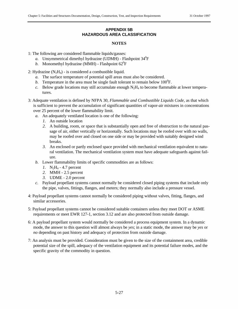
Chapter 5: Facilities and Structures Documentation, Design, Construction, Test, and Inspection Requirements 31 October 1997
APPENDIX 5BHAZARDOUS AREA CLASSIFICATION
5-27
NOTES
1: The following are considered flammable liquids/gasses:a. Unsymmetrical dimethyl hydrazine (UDMH) - Flashpoint 340Fb. Monomethyl hydrazine (MMH) - Flashpoint 620F
2: Hydrazine (N2H4) - is considered a combustible liquid.a. The surface temperature of potential spill areas must also be considered.b. Temperature in the area must be single fault tolerant to remain below 1000F.c. Below grade locations may still accumulate enough N2H4 to become flammable at lower tempera-
tures.
3: Adequate ventilation is defined by NFPA 30, Flammable and Combustible Liquids Code, as that whichis sufficient to prevent the accumulation of significant quantities of vapor-air mixtures in concentrationsover 25 percent of the lower flammability limit.a. An adequately ventilated location is one of the following:
1. An outside location2. A building, room, or space that is substantially open and free of obstruction to the natural pas-
sage of air, either vertically or horizontally. Such locations may be roofed over with no walls,may be roofed over and closed on one side or may be provided with suitably designed windbreaks.
3. An enclosed or partly enclosed space provided with mechanical ventilation equivalent to natu-ral ventilation. The mechanical ventilation system must have adequate safeguards against fail-ure.
b. Lower flammability limits of specific commodities are as follows:1. N2H4 - 4.7 percent2. MMH - 2.5 percent3. UDME - 2.0 percent
c. Payload propellant systems cannot normally be considered closed piping systems that include onlythe pipe, valves, fittings, flanges, and meters; they normally also include a pressure vessel.
4: Payload propellant systems cannot normally be considered piping without valves, fitting, flanges, andsimilar accessories.
5: Payload propellant systems cannot be considered suitable containers unless they meet DOT or ASMErequirements or meet EWR 127-1, section 3.12 and are also protected from outside damage.
6: A payload propellant system would normally be considered a process equipment system. In a dynamicmode, the answer to this question will almost always be yes; in a static mode, the answer may be yes orno depending on past history and adequacy of protection from outside damage.
7: An analysis must be provided. Consideration must be given to the size of the containment area, crediblepotential size of the spill, adequacy of the ventilation equipment and its potential failure modes, and thespecific gravity of the commodity in question.