Embed Size (px)
Citation preview
MIL-L-22624A (Wep)
MIL-L-22624 (Wep)15 August 1960
MILITARY SPECIFICATION
LINK, AMMUNITION, 20MM, MARK 6 MODS 4, 5, AND 6
(ASSEMBLY)
1. SCOPE
1.1 Scope. This specification covers the 20MM Ammu-nition Link Mark 6 Mods 4, 5, and 6, referred to hereinas the Link.
2. APPLICABLE DOCUMENTS
2.1 The following documents of the issue in effect ondate of invitation for bids form a part of this specifi-cation to the extent specified herein.
SPECIFICATIONS
Military
MIL-P-16232
STANDARDS
Federal
Federal Test MethodStandard No. 151
Military
MIL-STD-105
MIL-STD-129
Phosphate Coatings, Heavy,Manganese or Zinc Base (forFerrous Metals).
Metals; Test Methods
Sampling procedures andTables for Inspection byAttributes.
Marking for Shipment andStorage.
FSC 1305
Downloaded from http://www.everyspec.com
MIL-L-22624A
DRAWINGS
Bureau of Naval Weapons(Code Ident. 10001)
LD 522056
LD 615425
LD 615433LD 615434
LD 615435
LD 615436
LD 615437
LD 615438
982519
1445196
Pod, Gun, Mark 4 Mod 0(Assembly ).Link, Ammunition, 20MM, .Mark 6 Mod 4 (Assembly).Kit, Tool, Gun Pod Ammunition.Link, Cartridge, 20MM,Leading, Mark 6 Mod 5(Assembly).Link, Cartridge, 20MM,Trailing, Mark 6 Mod 6(Assembly ).20MM Link Packaging, Mark 6Mod 4.20MM Link Packaging, Mark 6Mod 5 Leading Link.20MM Link Packaging, Mark 6Mod 6 Trailing Link.Target Practice Round, 20MM,Mark 105 Mod 0.Dummy Round, 20MM, Mark 104Mod 0.
PUBLICATIONS
Bureau of Naval Weapons( Code Ident. 10001)
OP 2719 Gun Pod Mk 4 Mod 0; Descrip-tion, Operation, and Mainte-nance e.
(Copies of documents required by contractors in connec-tion with specific procurement functions should be obtainedfrom the procuring activity or as directed by the contract-ing officer.)
3. REQUIREMENTS
3.1 Preproduction sample. Unless otherwise specified inthe contract or order, a preproduction sample of linksshall be delivered for testing at a facility designatedin the contract or order (see 6.2). The links shall bedelivered as follows:
2
Downloaded from http://www.everyspec.com
MIL-L-22624A
(a) 486 links shall be Mod 4 links.(b) 36 links shall be Mod 5 links.(c) 36 links shall be Mod 6 links.
Fifty-two of the Mod 4 links shall be delivered unbelted.The remainder shall be belted into one belt of 60 links,seven belts of 50 links, one belt of 13 links, and onebelt of 11 links. The preproduction sample shall be manu-factured using the methods proposed for production. Anyproduction by the supplier prior to approval of the pre-production sample shall be at the suppliers risk.
3.2 Compliance with documents. Unless otherwise speci-fied, the link shall be in accordance with the require-ments specified herein and in the applicable documentslisted in section 2.
3.3 Materials. Materials used in the manufacture of thelink shall conform to the material specifications listedIn the applicable drawings (see section 2).
3.4 Construction. The link shall meet the requirementsspecified in 3.4 .1 to 3.4.8, inclusive. Nomenclature forlink component parts shall be as specified in Figure 1.
3.4.1 Round retention. When tested as specified in4.6.1.3, the link detent shall retain the stud simu-lating the ammunition round at the extractor groove.
3.4.2 Round separation. When tested as specified in4.6.1.4, the link shall permit the stud simulating theammunition round to separate from the link.
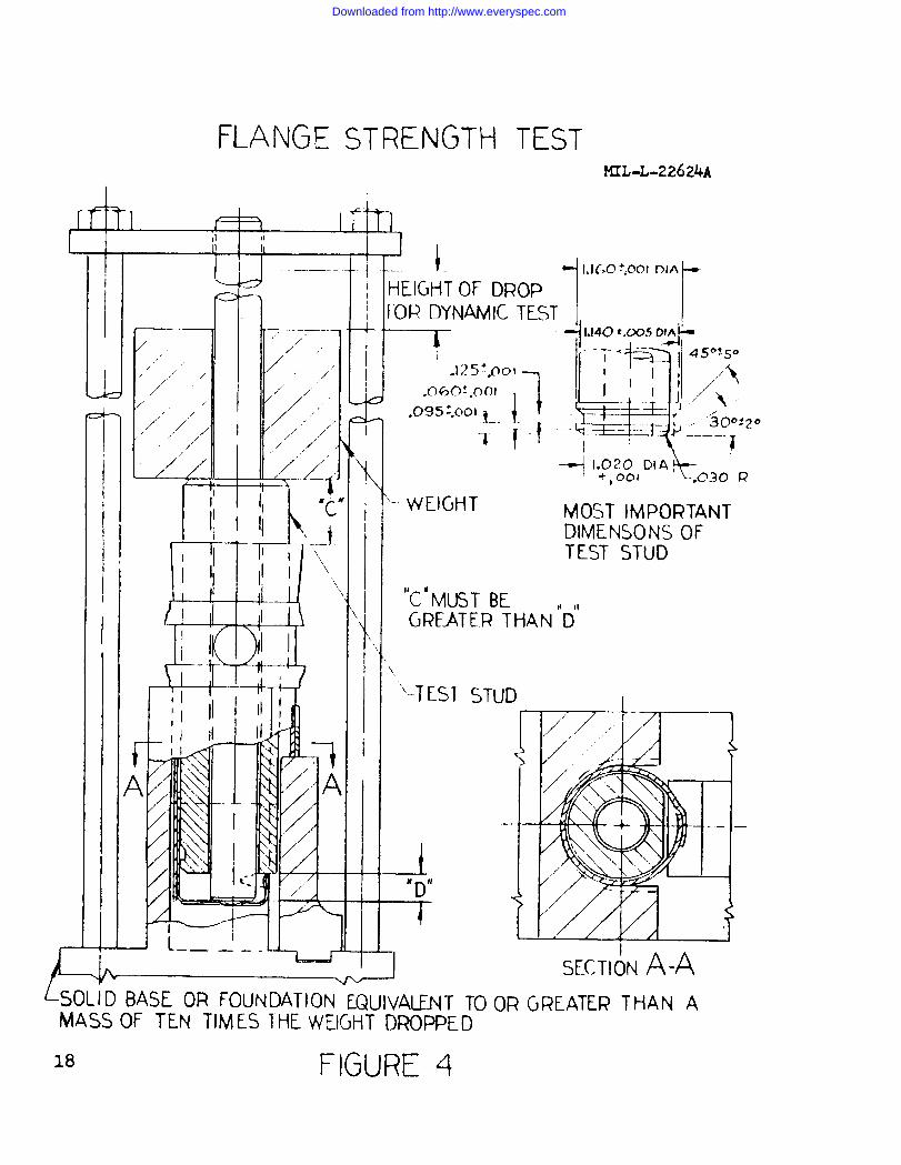
3.4.3 Flange strength. When the link is tested as speci-fied in 4.6.1.5 , the carrier flanges shall not be deformedto an extent that would permit them to pass beyond theextractor groove in the test stud.
3.4.4 Linking. The lug of any link shall engage com-pletely with the spring and rivet of any link when as-sembled using the linking tool assembly shown in drawingslisted in Lists of Drawings (LD) 615433.
3.4.5 Unlinking. The lug of one link shall not disengagefrom the spring and rivet of an adjacent link when thelinks are subjected to the test of 4.6.1.7 (a). Matingparts of two adjacent links shall disengage when thelinks are subjected to the test of 4.6.1.7 (b).
3
Downloaded from http://www.everyspec.com
MIL-L-22624A
3.4.6 Pitch distance. Pitch distance shall be defined asshown In Figure 1. The pitch distance for the Mark 6 Mod 4link shall be 1.601 inches plus or minus 0.024 inch.
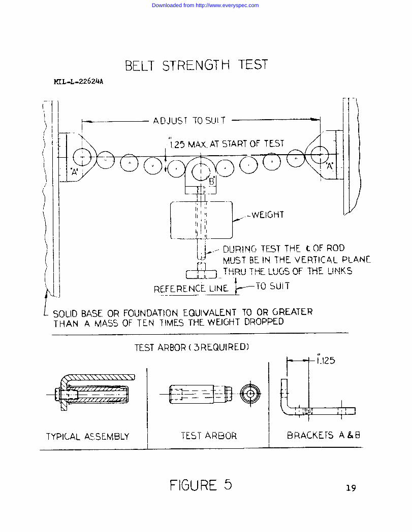
3.4.7 Belt strength. When tested as specified in 4.6.1.9,the ammunition belt formed by the links shall not separate.The increase in average pitch distance of the links shallnot exceed 0.010 inch.
3.4.8 Belt flexibility.
3.4.8.1 Twist. The belt formed by the links shall becapable of being twisted 360 degrees in not more than 13links.
3.4.8.2 Fanning. projectile end out. Belted links, loadedwith dummy ammunition rounds (see 3.7), shall be fanned ina circular pattern with the flanged ends of the carrierstouching. The diameter of the circle, measured across thetips of the projectiles, shall be not more than 40.0 inches.
3.4.8.3 Fanning. case end out. Twenty-five belted links,loaded with dummy ammunition rounds. shall be fanned in acircular pattern-on a smooth surface with the projectileends of the rounds pointing Inward. The loop formed shallnot exceed 20 inches overall (flanged end to flanged end).
3.4.8.4 Stacking. There shall be sufficient flexibilityin roll to assure feeding a loaded belt into a stacked con-figuration and withdrawing the belt from that configuration.Roll is defined as belt flexibility about the longitudinalcenterline of the individual links.
3.5 Performance characteristics. Links formed into beltsand loaded with 20MM, Mark 100 series ammunition shall becapable of fitting into and functioning with the Mark 4 GunPod and its components (Mark 11 Gun Mechanism and Mark 2Loader). See 3.7 and 3.8.
3.5.1 Belt feeding. Belted links shall be capable ofbeing withdrawn from the gun pod magazine or from stowagecontainers at the prescribed rate of fire of the gun. Thebelted links shall pass through feed chutes without catch-ing or binding.
3.5.2 Link positioning. The belted links of 3.5.1 shallengage the sides of the loader link guide rail and passbetween the guide rail and the loader sprockets withoutcatching or binding. During the loader ramming operation,
Downloaded from http://www.everyspec.com
MIL-L-22624A
the links shall permit stripping of ammunition rounds.
3.5.3 Link and case election. When an empty cartridgecase or a cartridge is ejected from the gun mechanismrevolver, the link receiving the case or cartridge shallunlink from its adjacent link. The link containing thecase or cartridge shall clear the loader without blockingsucceeding ejected links.
3.6 Environmental requirements.
3.6.1 Resistance to salt spray. Each link tested inaccordance with 4.6.1.2 shall be examined visually forevidence of rust. Rust staining and rust drainage shallnot be considered when measuring the area of rust spots.Each carrier assembly shall show not more than six rustspots, each measuring not more than 1/8 Inch in diameteror equivalent area. Each loop shall show not more thanthree rust spots of the specified diameter. Each lug andeach spring shall show not more than one rust spot of thespecified diameter. Not more than one rust spot, detect-able using a 15 power reading lens, Is permissible on therivet.
3.6.2 Temperature extremes. The belted links shall feedammunition into the loader, permit ramming of ammunitionrounds, accept and retain ejected cartridge cases or car-tridges, and unlink from adjacent links at any temperaturebetween minus 65 degrees Fahrenheit (F.) and plus 165degrees F.
3.7 Government-furnished property. The following, Inquantities specified in the contract or order, are re-quired to determine compliance of the link with the re-quirements of this specifications
(a) Target Practice Rounds, 20MM Mark 105Mod 0.
(b) Dummy Rounds, 20MM, Mark 104 Mod 0.
3.8 Government-loaned property. The following are re-quired to determine link conformance to the requirementsof this specification:
(a) Loader, Gun, 20MM, Mark 2 Mod 1.(b) Gun Mechanism, 20 MM, Mark 11 Mod 5.(c) Pod Assembly (for Gun Pod Mark 4
Mod 0).(d) Ejector Rack Assembly. Aero 7A-1.
5
Downloaded from http://www.everyspec.com
MIL-L-22624A
3.9 Packaging. packing and marking. Packaging, packingand marking of the link shall conform to the requirementsof section 5 of this specification.
3.10 Workmanship. Links shall be uniform in quality andtemper and shall be free from splits, cracks, scale,scrapes and other defects. The quality of workmanshipshall assure conformance to all requirements of thisspecification and the applicable documents listed in sec-tion 2.
4. QUALITY ASSURANCE PROVISIONS
4.1 Responisibility for inspection. Unless otherwise speci-fied in the contract or purchase order, the supplier Is re-sponsible for the performance of all inspection require-ments as specified herein. Except as otherwise specified,the supplier may utilize his own facilities or any commer-cial laboratory acceptable to the Government. The Govern-ment reserves the right to perform any of the inspectionsset forth In this specification where such inspections aredeemed necessary to assure that supplies and services con-form to prescribed requirements.
4.2 Classification of tests. The inspection and testingof the link shall be classified as follows:
(a) Preproduction tests.(b) Acceptance tests.
4.3 Lot. A lot shall consist of all links manufacturedby the same process at the same plant location andmitted for Government acceptance at the same time,that the lot size shall not exceed 25,000 links.
sub-except
4.4 Sampling. Unless otherwise specified herein,provisions set forth in Standard MIL-STD-105 shallthe establishment of sampling plans and proceduresinspection by attributes.
thegovernfor
4.5 Examination.
4.5.1 Components. Prior to assembly of the link, itshall be ascertained that all components procured underseparate documents have been inspected, tested, and ac-cepted In accordance with their respective documents.
4.5.2 Packing and marking. It shall be ascertained thatpacking and marking of the links conform to the require-ments of this specification.
6
Downloaded from http://www.everyspec.com
MIL-L-22624A
4.6 Tests.
4.6.1 Acceptance tests.
4.6.1.1 Visual and mechanical inspection. Link samplesselected in accordance with 4.4 shall be tested for con-formance to 3.2, 3.3, and 3.10. Lot quality shall bejudged as specified in 4.6.2.
4.6.1.2 Salt spray resistance test. After componentsof the Mod 4 link have received the phosphate coatingof Specification MIL-P-16232, 10 samples of the assembledlink shall be subjected to the test of Federal Test MethodStandard No. 151, Method 811.1. The link shall meet therequirements of 3.6.1. Test links shall not be reused forother tests nor shall they be delivered to the Governmentas units of production.
4.6.1.3 Round retention test. Ten Mod 4 links, 10 Mod 5links and 10 Mod 6 links shall be selected for the roundretention test. The test shall be performed using theequipment shown in Figure 3. The test fixture weight of2.0 pounds shall be allowed to fall freely a distance of4.0 inches and strike the test stud. The link shall meetthe requirements of 3.4.1.
4.6.1.4 Round separation test. The sample links and testequipment of 4.6.1.3 shall be reused for this test. Theweight shall be allowed to fall freely a distance of 11.0inches and strike the test stud. The link shall meet therequirements of 3.4.2.
4.6.1.5 Flange strength test. The test samples of 4.6.1.3and 4.6.1.4 shall be used with the equipment shown inFigure 4. The test fixture stud shall be positioned torest against the upper edges of the carrier detents. Theweight of 20.0 pounds shall be allowed to fall freely adistance of 30 inches and strike the stud. The link shallmeet the requirements of 3.4.3.
4.6.1.6 Linking test. Twenty Mod 4 links, 10 Mod 5 linksand 10 Mod links shall be selected for the linking test.The test shall be performed using the hand linking tool of3.4.4. Ten Mod 4 links shall be Joined as a single belt.The Mod 5 and Mod 6 links will be joined by a Mod 4 linkfor 10 groups of three. The lug slot of one link shall bepositioned to receive the spring and rivet of another link.The link shall meet the requirements of 3.4.4.
7
Downloaded from http://www.everyspec.com
MIL-L-22624A
4.6.1.7 Unlinking test. Link samples used in the testof 4.6. 1.6 shall be tested using the equipment shown inFigure 2. The test shall be performed in two stages, asfollows:
(a )
(b)
The test fixture weight of 2.0 poundsshall be allowed to fall freely a dis-tance of 3.0 inches and strike the teststud. Test samples unlinking from eachother are defective. If partial disen-gagement occurs, the links shall be re-stored to their original test positionfor test (b).
The same weight shall be allowed to fallfreely a distance of 12.0 inches. Testsamples failing to disengage completelyare defective.
4.6.1.8 Pitch distance test. Eleven Mod 4 links shallbe linked and loaded with dummy rounds (see 3.7) and sus-pended vertically from an appropriate holding device.
)The
pitch distance (defined as shown in Figure 1 shall bemeasured between the rivet of the second link and the rivetof the last link. The link shall meet the requirements of3.4.6.
4.6.1.9 Belt strength test. The belted links of 4.6.1.8shall be reused with the test equipment shown In Figure 5.The test arbors shall be used to attach the weight assemblyto the center link and to attach the first and last linksto their mounting brackets. Measure the distance from thebottom of the weight assembly to the reference line. Raisethe 8.0 pound weight 18 inches and release it. Again measurethe distance between the weight assembly and the referenceline. If the change in measurement exceeds 0.288 inch, theincrease in link pitch does not meet the requirements of3.4.7.
4.6.1.10 Twist test. Thirteen Mod 4 links shall be beltedand tested for conformance to 3.4.8.1.
4.6.1.11 Fanning test, projectile ends out. Sixty Mod 4links shall be belted, loaded with dummy rounds, and placedon a plane surface. The links shall be fanned in a circlewith the flanged ends of the carriers touching. The beltmay be separated to provide the number of belted links nec-essary to determine conformance to 3.4.8.2.
8
Downloaded from http://www.everyspec.com
MIL-L-22624A
4.6.1.12 Fanning test, case ends out. A 25 round beltseparated from the belt of 4.6.1.11 shall be used. The testshall be performed using a horizontal plane surface of plateglass or equivalent. The links shall be fanned in a circularpattern by applying manual pressure to each of the end links.Manual pressure shall be released slowly to minimize spring-back. The links shall then be examined for conformance to3.4.8.3.
4.6.1.13 Stacking test. Each Mark 6 Mod 4 link intendedfor delivery to the Government shall be belted into beltsof 50 links and the belt placed on a plane surface. Oneend of the belt shall be lifted from the surface, movedover the adjoining links and toward the opposite end of thebelt. If each link subassembly (Drawing 2471117) does notrotate completely, one at a time, as the belt is so liftedand drawn, the link does not meet the requirements of3.4.8.4. The tests shall be repeated by moving the oppo-site end of the belt over adjoining links. Defective linksshall be discarded and the tests shall be repeated.
4.6.2 Acceptance criteria. Lot quality for the accept-ance tests of 4.6.1.1 shall be judged in accordance withStandard MIL-STD-105, Acceptable Quality Level (AQL) 1.0percent defective. Failure of the link to meet the require-ments of 3.4.1 through 3.48.3 shall be cause for rejectionof the lot represented. Resubmittal of unacceptable lotsshall be as specified in the contract or order (see 6.2).
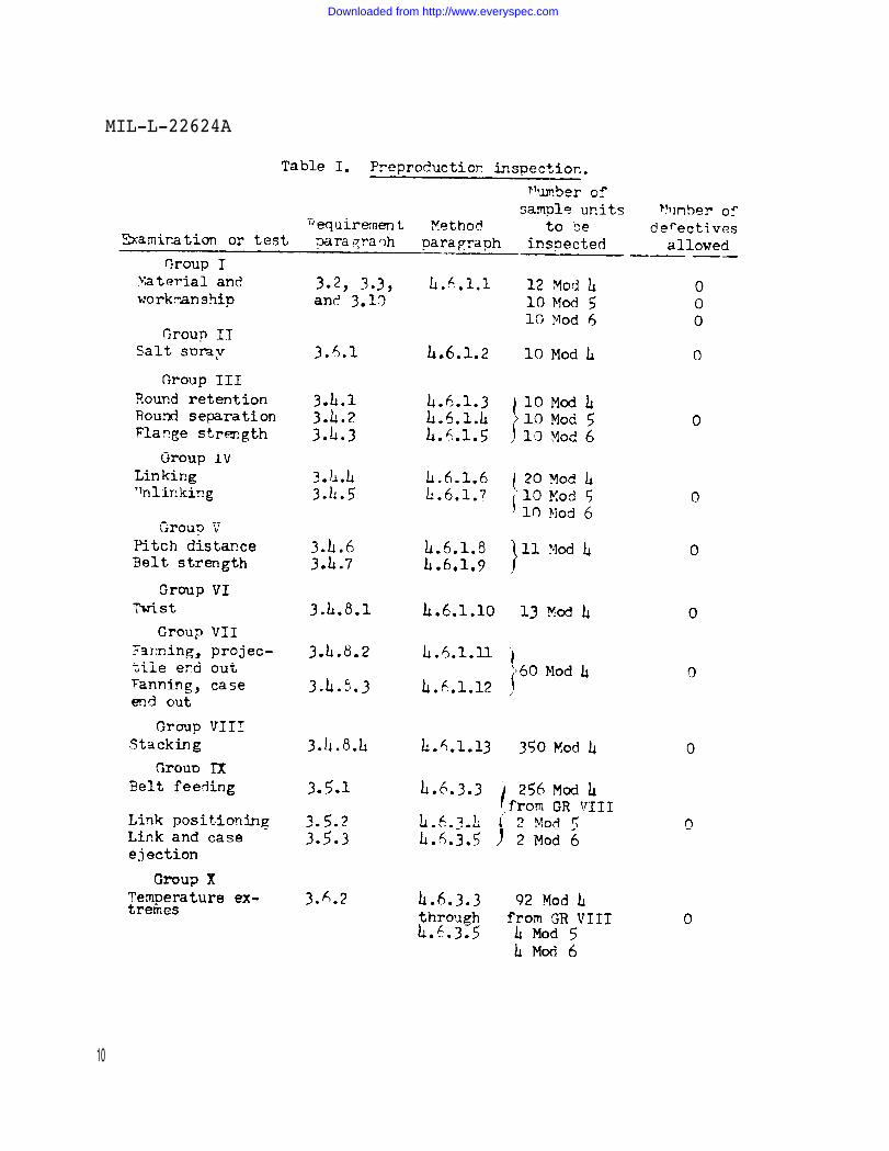
4.6.3 Reproduction tests. The preproduction tests shallinclude all of the acceptance tests of 4.6.1.1 to 4.6.1.13,inclusive, and the function tests of 4.6.3.3 to 4.6.3.5,inclusive. Preproduction tests shall be performed as speci-fied herein and in Table I.
4.6.3.1 Temperature-conditioning. The Government-loanedproperty of 3.8 (a), (b), and (c) shall be assembled intothe Gun Pod Mark 4 Mod 0. Link samples shall be beltedInto four belts of 25 links, each composed as follows: oneMod 5 leading
6link, followed in order by 23 Mod 4 links
and one Mod trailing link. The belts shall be loadedwith Mark 105 target practice rounds, except that eachleading link shall remain empty. TWO belts shall be loadedinto the ammunition magazine as specified in PublicationOP 2719, and the assembled gun pod shall be temperature-con-ditioned at minus 65 degrees F. plus 10.0 degrees F. minus 5.0degrees F. until all components have been thermally stabilizedat the specified temperature. The gun pod shall then be firedas specified in 4.6.3.3. After firing, any required gun podmaintenance shall be performed as specified in Publication
9
Downloaded from http://www.everyspec.com
MIL-L-22624A
10
Downloaded from http://www.everyspec.com
MIL-L-22624A
OP 2719. The two remaining belts shall be loaded into themagazine, and the gun pod shall be temperature-conditionedat 165 degrees F. plus 5.0 degrees F. minus 10.0 degrees F.until all components have been thermally stabilized at thespecified temperature. The gun pod shall be fired as speci-fied in 4.6.3.3.
4.6.3.2 Samples for ambient temperature testing. Samplelinks shall be belted into two belts of 130 links, eachcomposed as follows: one empty leading link, followed by128 Mod 4 links and one trailing link. The Mod 4 linksand the trailing link shall be loaded with Mark 105 targetpractice rounds. The belts shall be loaded into the ammu-nition magazine of the assembled gun pod and shall besubjected to the tests of 4.6.3.3, 4.6.3.4, and 4.6.3.5
4.6.3.3 Belt feeding test. The assembled gun pod shallbe prepared for firing as specified in Publication OP 2719.The gun mechanism shall be cycled and each pair of beltscomposed of 25 links shall be fired through the gun pod ina single burst. The belts composed of 130 links shall befired in three bursts of approximately 86 rounds per burst.Failure of any link to meet the requirements of 3.5.1 and3.6.2 shall be cause for rejection of the preproductionsample. The link shall not be judged defective if it isverified to the satisfaction of the Government representa-tive that a stoppage or other malfunction was caused by acomponent other than the links under test.
4.6.3.4 Link positioning test. Belted and loaded links,fired as specified in 4 .6.3.3, shall be tested for con.formance to 3.5.2 and 3.6.2. Failure to meet these re-quirements shall be cause for rejection of the preproduc-tion sample. The link shall not be judged defective if itis verified to the satisfaction of the Government repre-sentative that a malfunction was caused by a componentother than the links under test.
4.6.3.5 Link and case ejection test. Belted and loadedlinks, fired as specified in 4.6.3.3, shall be tested forconformance to 3.5.3 and 3.6.2. Failure to meet these re-quirements shall be cause for rejection of the preproduc-tion sample. The link shall not be judged defective if itis verified to the satisfaction of the Government representa-tive that a malfunction was caused by a component other thanthe links under test.
5. PREPARATION FOR DELIVERY
11
Downloaded from http://www.everyspec.com
MIL-L-22624A
5.1 Preservation and packaging. Preservation and packagingshall be level A, B, or C, as specified (see 6.2).
5.1.1 Level A.
5.1.1.1 Preservation application. The supplementary oilfinish of Specification MIL-P-16232, applied subsequent tophosphate coating, shall serve as the preservative for eachMod 4 link. Mod 5 and Mod 6 links shall be painted in ac-cordance with their applicable documents. No additionalpreservation is required for Mods 4, 5, and 6 links.
5.1.1.2 Unit packaging. Not applicable.
5.1.2. Level C.
5.1.2.1 Preservation application. Presentation applicationshall be as specified in 5.1.1.1.
5.1.2.2 Unit packaging. Not applicable.
5.2 Packing.
5.2.1 Level A.
5.2.1.1 Exterior containers. Mod 4 links, in numbers speci-fied in the contract or order (see 6.2), shall be beltedinto ammunition belts and packed into containers conformingto drawings listed in LD 615436. Mod 5 links, in quantitiesspecified in the contract or order, shall be packed intocontainers conforming to LD 615437. Mod 6 links, in quanti-ties specified in the contract or order, shall be packedinto containers conforming to LD 615438.
5.2.1.2 Cushioning. The pack shall incorporate sufficientcushioning material, bracing, or other adequate shock ab-sorbing devices, to ensure that the link will meet all ofthe requirements of section 3.
5.2.2. Level C.
5.2.2.1 Exterior containers. Links shall be packed toafford protection against damage during direct shipmentfrom the supply source to the first receiving activityfor immediate use. Shipping containers shall conform tothe carrier rules and regulations applicable to the modeof transportation.
12
Downloaded from http://www.everyspec.com
MIL-L-22624A
5.3 Marking.
5. 3.1 Special marking. None, unless otherwise specified.
5.3.2 Normal marking. In addition to the marking requiredby the contract or order, shipping containers shall bemarked in accordance with Standard MIL-STD-129.
6. NOTES
6.1 Intended use. The links covered by this specificationare intended for linking into 20MM ammunition belts for usewith the 20MM Aircraft Gun Mark 11 Mod 5.
6.2 Ordering data. Procurement documents should specifythe following:
(a)(b)
(c)
(d)(e)(f)(g)(h)(i)
(j)
Title, number and date of this specification.Size of preproduction sample if differentfrom 3.1.Facility designated to evaluate the prepro-duction sample.Government-furnished property (see 3.7).Government-loaned property (see 3.8).Lot size If different from 4.3.Procedure for resubmittal of rejected lots.Preservation, packaging and w.eking levels.Special marking of shipping containers ifrequired.Invocation of Specification MIL-Q-9858.
6.3 Reliability. Extreme care must be exercised in es-tablishing the production system and quality controlpractices for parts covered by this specification to assurean adequate overall gun system reliability. Each subsystemmust have considerably higher individual reliability thanthe overall 7,000 rounds per stoppage needed for the Mark 4Gun Pods of which this item is a part. These reliabilitiescannot be assured by an after the fact inspection to an AQLand are therefore beyond the written requirement of thespecification. However, it has been shown that high relia-bilities can be achieved even though inspection AQL’s arerelatively low (ammunition, for example) if a good productionsystem and control Is followed. To Illustrate the componentrequirement, the subsystems must perform to stoppage rates nogreater than those listed below if the 7,000 rounds per stoppage
13
Downloaded from http://www.everyspec.com
MIL-L-22624A
reliability level of the Mark 4 Gun Pod is to be maintained.
Item Stoppage/rounds fired
Ammunition 1/100,000Link 1/100,000Loader 1/20,000Gun 1/20,000Pod 1/50,000
14
Downloaded from http://www.everyspec.com
Downloaded from http://www.everyspec.com
Downloaded from http://www.everyspec.com
Downloaded from http://www.everyspec.com
Downloaded from http://www.everyspec.com
Downloaded from http://www.everyspec.com

Downloaded from http://www.everyspec.com
Downloaded from http://www.everyspec.com
Downloaded from http://www.everyspec.com