Embed Size (px)
DESCRIPTION
5 Planning Topics
Citation preview
1 © Nokia Siemens Networks Presentation / Author / DateCompany Confidential
Planning TopicsRadio Network Design for Roll-Outs (RNDR) PCI Planning PRACH Planning UL DM RS Planning TAC Planning
2 © Nokia Siemens Networks Presentation / Author / DateCompany Confidential
PCI Planning
3 © Nokia Siemens Networks Presentation / Author / DateCompany Confidential
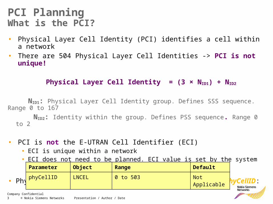
PCI PlanningWhat is the PCI?• Physical Layer Cell Identity (PCI) identifies a cell within a network• There are 504 Physical Layer Cell Identities -> PCI is not unique!
Physical Layer Cell Identity = (3 × NID1) + NID2
NID1: Physical Layer Cell Identity group. Defines SSS sequence. Range 0 to 167 NID2: Identity within the group. Defines PSS sequence. Range 0 to 2
• PCI is not the E-UTRAN Cell Identifier (ECI)• ECI is unique within a network• ECI does not need to be planned. ECI value is set by the system
• Physical Cell Identity is defined by the parameter phyCellID:
Parameter Object Range DefaultphyCellID LNCEL 0 to 503 Not Applicable
4 © Nokia Siemens Networks Presentation / Author / DateCompany Confidential
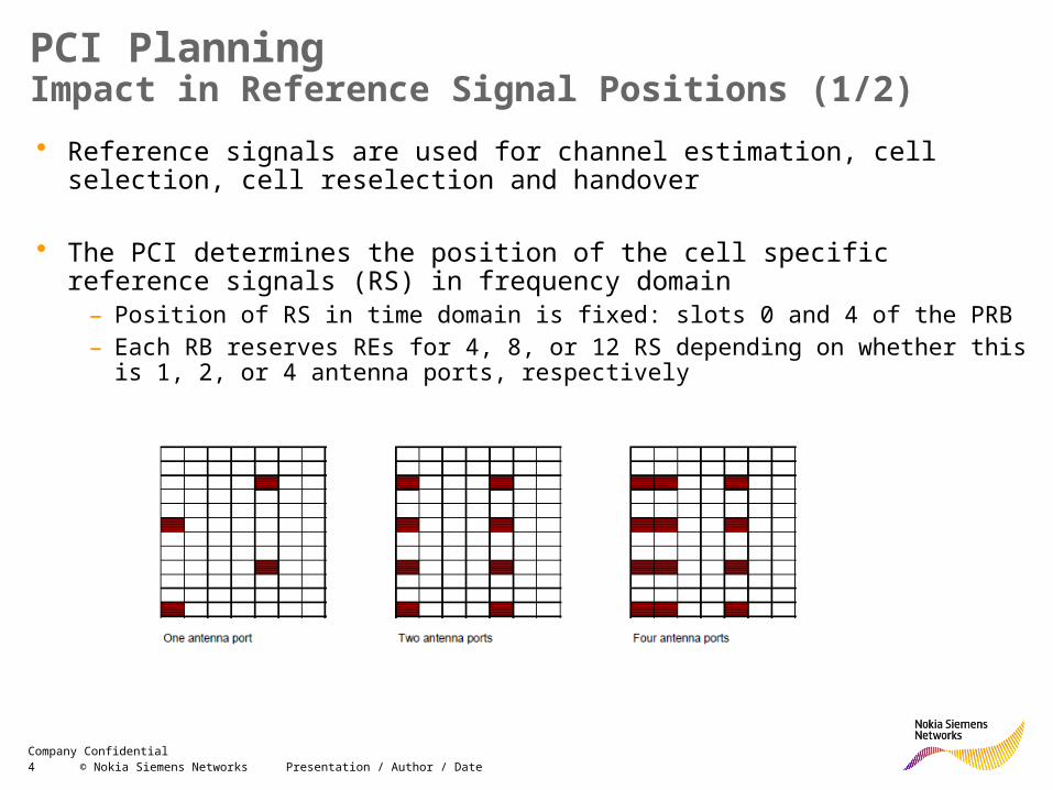
PCI PlanningImpact in Reference Signal Positions (1/2)• Reference signals are used for channel estimation, cell selection, cell reselection
and handover
• The PCI determines the position of the cell specific reference signals (RS) in frequency domain
– Position of RS in time domain is fixed: slots 0 and 4 of the PRB– Each RB reserves REs for 4, 8, or 12 RS depending on whether this is 1, 2, or 4
antenna ports, respectively
5 © Nokia Siemens Networks Presentation / Author / DateCompany Confidential
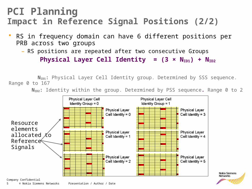
PCI PlanningImpact in Reference Signal Positions (2/2)• RS in frequency domain can have 6 different positions per PRB across two groups
– RS positions are repeated after two consecutive GroupsPhysical Layer Cell Identity = (3 × NID1) + NID2
NID1: Physical Layer Cell Identity group. Determined by SSS sequence. Range 0 to 167 NID2: Identity within the group. Determined by PSS sequence. Range 0 to 2
Resource elements allocated to Reference Signals
6 © Nokia Siemens Networks Presentation / Author / DateCompany Confidential
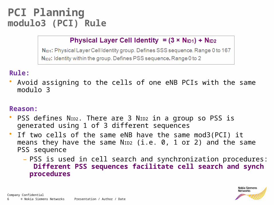
PCI Planningmodulo3 (PCI) Rule
Rule: • Avoid assigning to the cells of one eNB PCIs with the same modulo 3
Reason:• PSS defines NID2. There are 3 NID2 in a group so PSS is generated using 1 of 3
different sequences• If two cells of the same eNB have the same mod3(PCI) it means they have the
same NID2 (i.e. 0, 1 or 2) and the same PSS sequence – PSS is used in cell search and synchronization procedures: Different PSS
sequences facilitate cell search and synch procedures
7 © Nokia Siemens Networks Presentation / Author / DateCompany Confidential
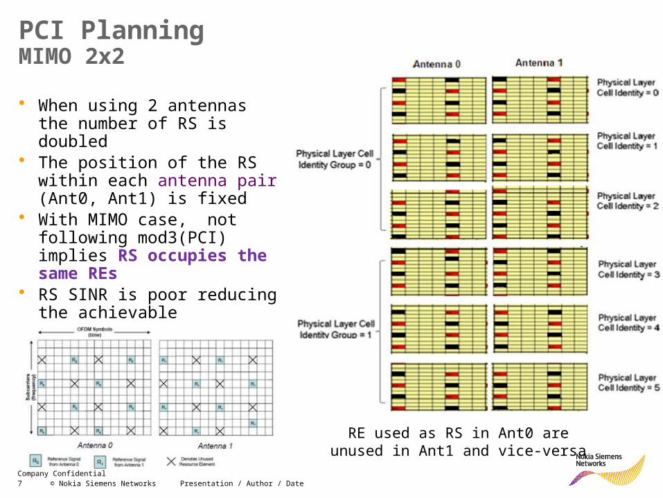
PCI PlanningMIMO 2x2
• When using 2 antennas the number of RS is doubled
• The position of the RS within each antenna pair (Ant0, Ant1) is fixed
• With MIMO case, not following mod3(PCI) implies RS occupies the same REs
• RS SINR is poor reducing the achievable throughput
RE used as RS in Ant0 are unused in Ant1 and vice-versa
8 © Nokia Siemens Networks Presentation / Author / DateCompany Confidential
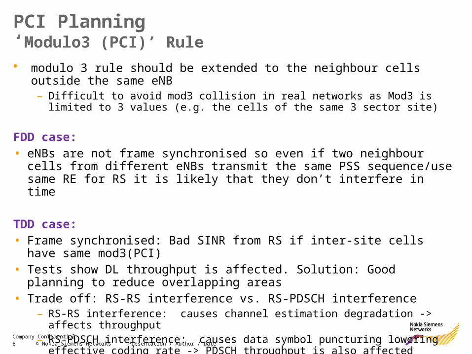
PCI Planning‘Modulo3 (PCI)’ Rule• modulo 3 rule should be extended to the neighbour cells outside the same eNB
– Difficult to avoid mod3 collision in real networks as Mod3 is limited to 3 values (e.g. the cells of the same 3 sector site)
FDD case:• eNBs are not frame synchronised so even if two neighbour cells from different
eNBs transmit the same PSS sequence/use same RE for RS it is likely that they don’t interfere in time
TDD case:• Frame synchronised: Bad SINR from RS if inter-site cells have same mod3(PCI)• Tests show DL throughput is affected. Solution: Good planning to reduce
overlapping areas• Trade off: RS-RS interference vs. RS-PDSCH interference
– RS-RS interference: causes channel estimation degradation -> affects throughput– RS-PDSCH interference: causes data symbol puncturing lowering effective coding rate
-> PDSCH throughput is also affected
10 © Nokia Siemens Networks Presentation / Author / DateCompany Confidential
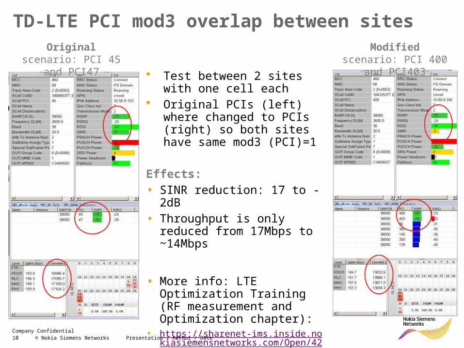
TD-LTE PCI mod3 overlap between sites
• Test between 2 sites with one cell each
• Original PCIs (left) where changed to PCIs (right) so both sites have same mod3 (PCI)=1
Effects: • SINR reduction: 17 to -2dB• Throughput is only reduced
from 17Mbps to ~14Mbps
• More info: LTE Optimization Training (RF measurement and Optimization chapter):
• https://sharenet-ims.inside.nokiasiemensnetworks.com/Open/426475080
Original scenario: PCI 45 and PCI47
Modified scenario: PCI 400 and PCI403
11 © Nokia Siemens Networks Presentation / Author / DateCompany Confidential
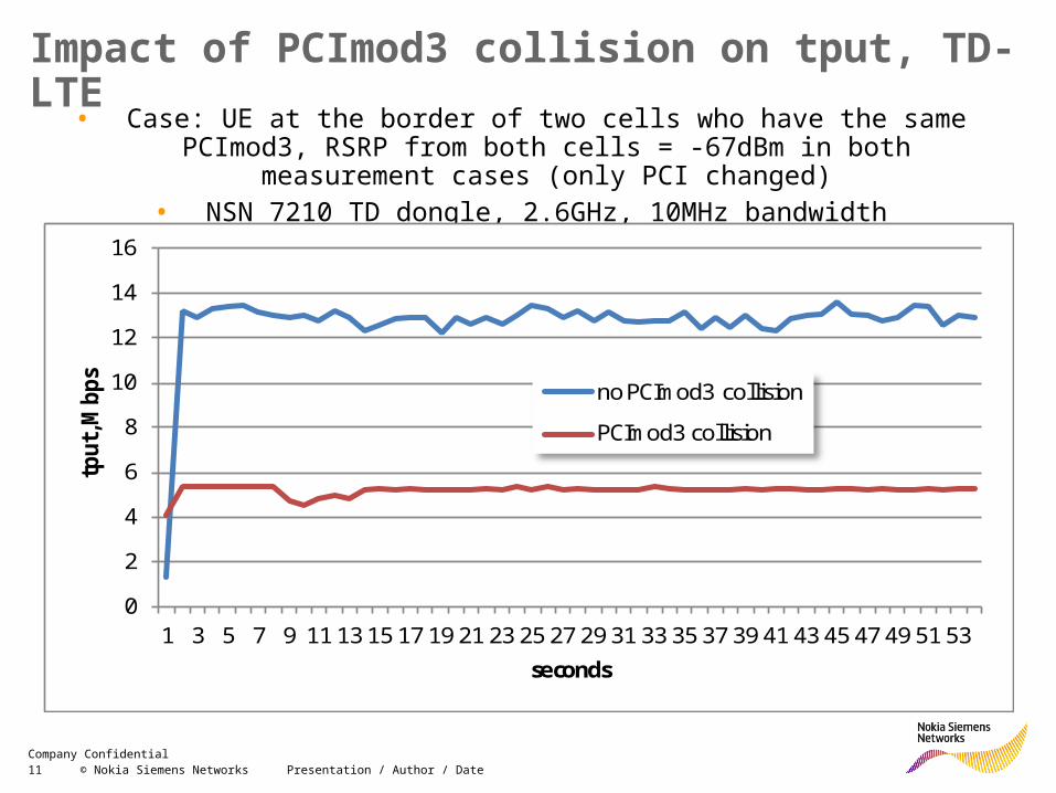
Impact of PCImod3 collision on tput, TD-LTE• Case: UE at the border of two cells who have the same PCImod3, RSRP
from both cells = -67dBm in both measurement cases (only PCI changed)• NSN 7210 TD dongle, 2.6GHz, 10MHz bandwidth
0
2
4
6
8
10
12
14
16
1 3 5 7 9 11 13 15 17 19 21 23 25 27 29 31 33 35 37 39 41 43 45 47 49 51 53
tput
, Mbp
s
seconds
no PCImod3 collision
PCImod3 collision
12 © Nokia Siemens Networks Presentation / Author / DateCompany Confidential
PCI Planning‘Modulo6(PCI)’ Rule
Rule: • If mod3(PCI) can’t be fulfilled, avoid assigning the same mod6(PCI) to the cells of
the same site
Reason:• 1Tx case: PSS sequence is not unique within the cells of a site but its position the
in frequency domain is still different -> not RS interference
• 2Tx case: RS to RS interference can not be avoided. The only way to avoid it when using MIMO2x2 is with the mod3(PCI) rule
Summary:• For 2Tx case the cells of the same site should have different mod3 (PCI). For 1Tx
case the mod6(PCI) should be different• Reason: To have frequency shifts for RS of different cells as they are frame-
synchronized (cells of the same site) and avoid RS interference in DL.
13 © Nokia Siemens Networks Presentation / Author / DateCompany Confidential
PCI Planning: ‘Modulo30(PCI)’ Rule‘Modulo 30’ Rule: • If mod6(PCI) can’t be fulfilled, avoid assigning the same module30(PCI) to the
cells of the same site
Reason: • mod30 is required in other planning areas like the UL Demodulation reference
signal planning
Example• There are 30 groups of sequences ‘u’ for PUSCH. Each cell within a site should
have sequences from different groups • If the PCIs for cells of the same site have different mod30 then ‘u’ (group
sequence number) is different and it is not necessary to plan the grpAssigPUSCH parameter
30modSCHgrpAssigPU PCIu
14 © Nokia Siemens Networks Presentation / Author / DateCompany Confidential
PCI PlanningRecommendations, wrap up
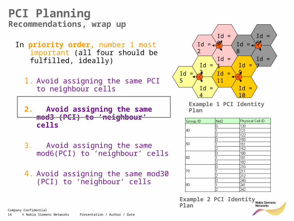
In priority order, number 1 most important (all four should be fulfilled, ideally)
1. Avoid assigning the same PCI to neighbour cells
2. Avoid assigning the same mod3 (PCI) to ‘neighbour’ cells
3. Avoid assigning the same mod6(PCI) to ‘neighbour’ cells
4. Avoid assigning the same mod30 (PCI) to ‘neighbour’ cells
Id = 5
Id = 4
Id = 3Id = 11
Id = 10
Id = 9
Id = 8
Id = 7
Id = 6Id = 2
Id = 1
Id = 0
Example 1 PCI Identity Plan
Example 2 PCI Identity Plan
15 © Nokia Siemens Networks Presentation / Author / DateCompany Confidential
PCI Planning6 sector sites• In 6 sectors sites is not possible to assign PCIs with different modulo 3 as we
have 6 cells and only 3 different possibilities
• If increasing sectorisation (from 3 to 6 sectors) then every second group of identities should be allocated within the initial plan
– To allow eNodeB to be allocated identities from two adjacent groups when the number of cells is increased from 3 to 6
Rule:• Planning should be done assigning PCIs from two consecutive groups and
avoiding that the consecutive cell (i+1) has the same modulo 3(PCI) • By assigning PCIs from two consecutive groups the ‘module6’ rule is followed
16 © Nokia Siemens Networks Presentation / Author / DateCompany Confidential
PCI Planning Methods
• Manual• Valid for small amount of sites (e.g. trials)• No need for additional tools, just follow the rules considering the site distance
and cell azimuths
• Atoll or other planning tools (e.g. Asset)• PCI planning supported – see next slide
• NetAct Optimizer• PCI planning supported
• NSN Internal tools (e.g. Alpha, MUSA)• Alpha: https://sharenet-ims.inside.nokiasiemensnetworks.com/Open/434150579• MUSA: https://sharenet-ims.inside.nokiasiemensnetworks.com/Open/428210505
17 © Nokia Siemens Networks Presentation / Author / DateCompany Confidential
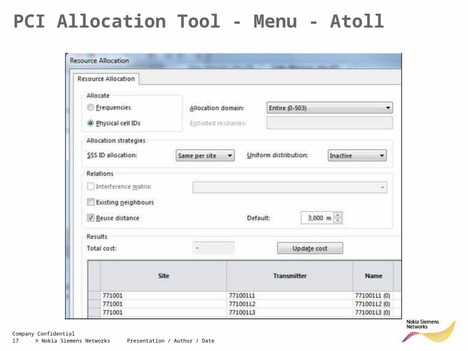
PCI Allocation Tool - Menu - Atoll
18 © Nokia Siemens Networks Presentation / Author / DateCompany Confidential
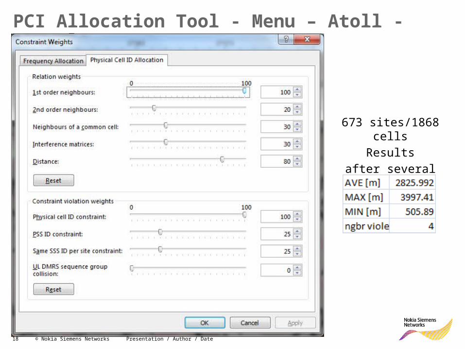
PCI Allocation Tool - Menu – Atoll - Example
673 sites/1868 cellsResults
after several hours
19 © Nokia Siemens Networks Presentation / Author / DateCompany Confidential
Minimum Re-use Distance for PCI Planning Achievable - Example
• Let take sample of network with certain average Inter Site Distance (ISD), 3 sector sites and all 504 PCI available.• PCI Allocation consume 1 secondary group per site => 168 groups
available and the radius of the ring containing 168 sites is the maximum achievable minimum PCI re-use distance.
• One site coverage area could be expressed as Site_area = 0.8 * ISD^2,
• Then 168 sites cover area S = 168 * Site_area = 168 * 0.8 * ISD^2,• The radius of such ring area is r = ISD*SQRT(168*0.8/3.14) = 6.5 *
ISD.
• The maximum achievable PCI re-use distance of 3 sector site network is about 6.5 * ISD
20 © Nokia Siemens Networks Presentation / Author / DateCompany Confidential
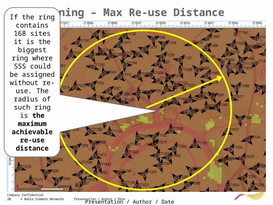
PCI Planning – Max Re-use Distance
Presentation / Author / Date
If the ring contains 168 sites it is the biggest ring where SSS
could be assigned
without re-use. The radius of such ring is
the maximum achievable
re-use distance
21 © Nokia Siemens Networks Presentation / Author / DateCompany Confidential
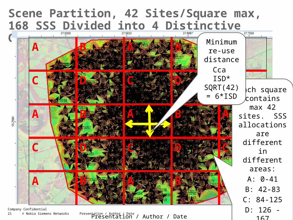
Scene Partition, 42 Sites/Square max, 168 SSS Divided into 4 Distinctive Groups A, B, C, D
Presentation / Author / Date
A B A B A
C D C D C
A B A B A
C DD C DD C
A B A B A
Each square contains max 42 sites. SSS allocations are
different in different areas:
A: 0-41B: 42-83
C: 84-125D: 126 - 167
Minimum re-use
distanceCca ISD* SQRT(42) = 6*ISD
22 © Nokia Siemens Networks Presentation / Author / DateCompany Confidential
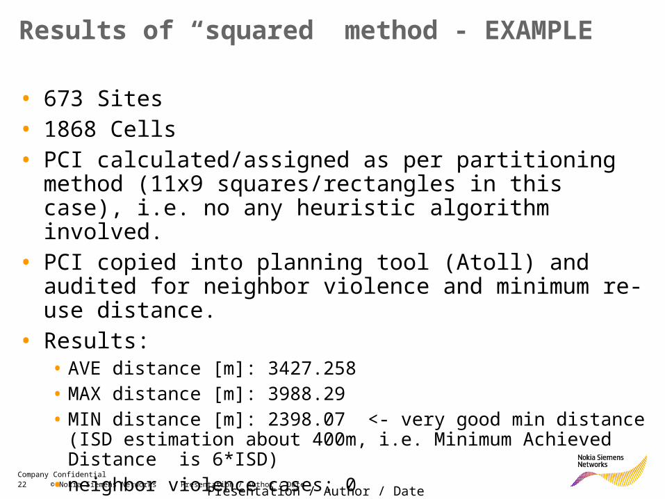
Results of “squared” method - EXAMPLE
• 673 Sites• 1868 Cells• PCI calculated/assigned as per partitioning method (11x9
squares/rectangles in this case), i.e. no any heuristic algorithm involved.
• PCI copied into planning tool (Atoll) and audited for neighbor violence and minimum re-use distance.
• Results: • AVE distance [m]: 3427.258 • MAX distance [m]: 3988.29 • MIN distance [m]: 2398.07 <- very good min distance (ISD estimation
about 400m, i.e. Minimum Achieved Distance is 6*ISD)• neighbor violence cases: 0
Presentation / Author / Date
23 © Nokia Siemens Networks Presentation / Author / DateCompany Confidential
PRACH Planning
24 © Nokia Siemens Networks Presentation / Author / DateCompany Confidential
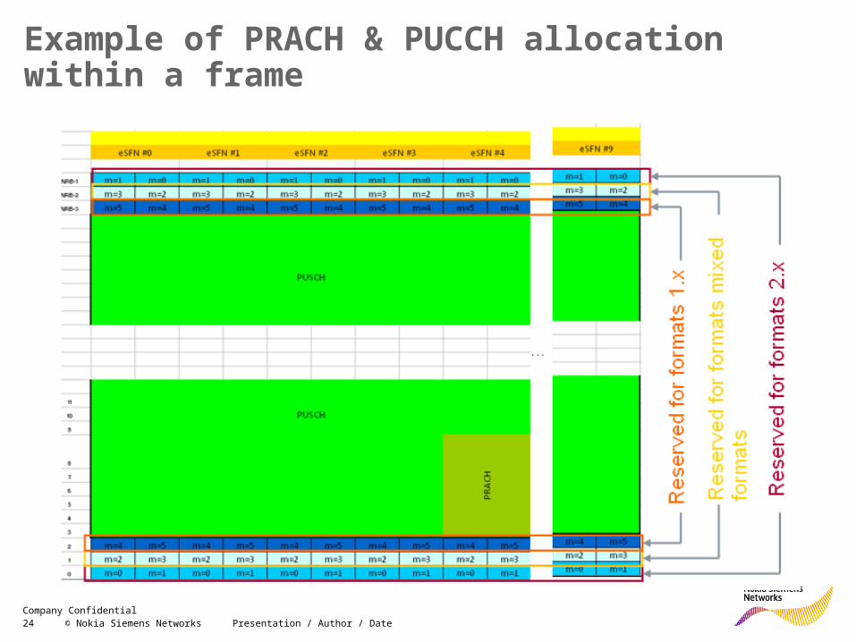
Example of PRACH & PUCCH allocation within a frame
25 © Nokia Siemens Networks Presentation / Author / DateCompany Confidential
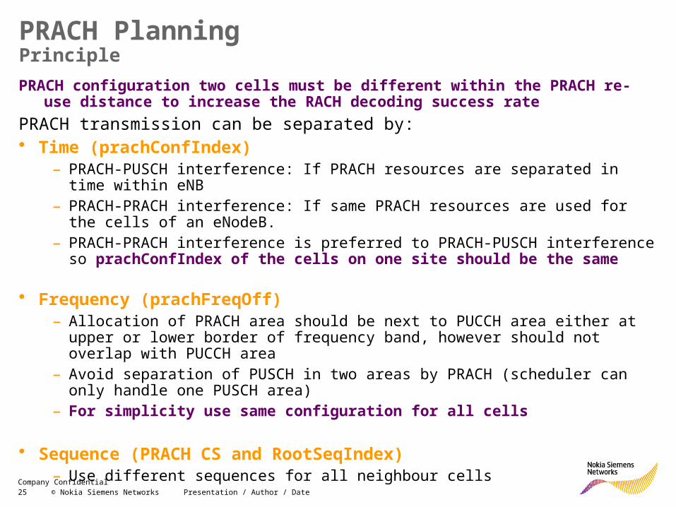
PRACH PlanningPrinciplePRACH configuration two cells must be different within the PRACH re-use distance to
increase the RACH decoding success ratePRACH transmission can be separated by:• Time (prachConfIndex)
– PRACH-PUSCH interference: If PRACH resources are separated in time within eNB– PRACH-PRACH interference: If same PRACH resources are used for the cells of an
eNodeB. – PRACH-PRACH interference is preferred to PRACH-PUSCH interference so
prachConfIndex of the cells on one site should be the same
• Frequency (prachFreqOff)– Allocation of PRACH area should be next to PUCCH area either at upper or lower
border of frequency band, however should not overlap with PUCCH area– Avoid separation of PUSCH in two areas by PRACH (scheduler can only handle one
PUSCH area)– For simplicity use same configuration for all cells
• Sequence (PRACH CS and RootSeqIndex)– Use different sequences for all neighbour cells
26 © Nokia Siemens Networks Presentation / Author / DateCompany Confidential
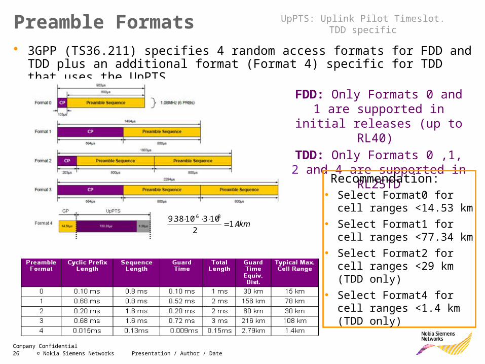
Preamble Formats• 3GPP (TS36.211) specifies 4 random access formats for FDD and TDD plus an
additional format (Format 4) specific for TDD that uses the UpPTS
• FDD: Only Formats 0 and 1 are supported in initial releases (up
to RL40) • TDD: Only Formats 0 ,1, 2 and
4 are supported in RL25TD
Recommendation: • Select Format0 for cell
ranges <14.53 km • Select Format1 for cell
ranges <77.34 km• Select Format2 for cell
ranges <29 km (TDD only)• Select Format4 for cell
ranges <1.4 km (TDD only)
UpPTS: Uplink Pilot Timeslot. TDD specific
km4.12
1031038.9 86
27 © Nokia Siemens Networks Presentation / Author / DateCompany Confidential
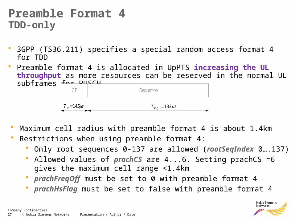
Preamble Format 4TDD-only
• 3GPP (TS36.211) specifies a special random access format 4 for TDD• Preamble format 4 is allocated in UpPTS increasing the UL throughput as more
resources can be reserved in the normal UL subframes for PUSCH
• Maximum cell radius with preamble format 4 is about 1.4km • Restrictions when using preamble format 4:
• Only root sequences 0-137 are allowed (rootSeqIndex 0….137)• Allowed values of prachCS are 4...6. Setting prachCS =6 gives the maximum
cell range <1.4km• prachFreqOff must be set to 0 with preamble format 4• prachHsFlag must be set to false with preamble format 4
SequenceCP
sT 5.14CP sT 133SEQ
28 © Nokia Siemens Networks Presentation / Author / DateCompany Confidential
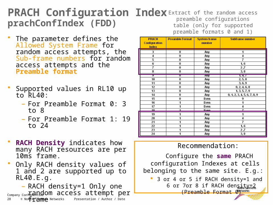
PRACH Configuration IndexprachConfIndex (FDD)• The parameter defines the Allowed
System Frame for random access attempts, the Sub-frame numbers for random access attempts and the Preamble format
• Supported values in RL10 up to RL40:– For Preamble Format 0: 3 to 8– For Preamble Format 1: 19 to 24
• RACH Density indicates how many RACH resources are per 10ms frame.
• Only RACH density values of 1 and 2 are supported up to RL40.E.g.
– RACH density=1 Only one random access attempt per frame
– RACH density=2 Two random access attempts per frame
Extract of the random access preamble configurations table (only for supported preamble formats 0 and 1)
Recommendation: Configure the same PRACH configuration
Indexes at cells belonging to the same site. E.g.:
3 or 4 or 5 if RACH density=1 and 6 or 7or 8 if RACH density=2 (Preamble Format 0)
29 © Nokia Siemens Networks Presentation / Author / DateCompany Confidential
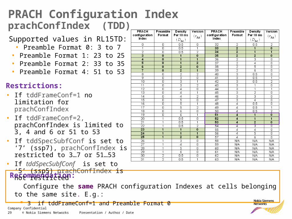
PRACH Configuration IndexprachConfIndex (TDD)
Supported values in RL15TD:• Preamble Format 0: 3 to 7
• Preamble Format 1: 23 to 25• Preamble Format 2: 33 to 35• Preamble Format 4: 51 to 53
Recommendation: Configure the same PRACH configuration Indexes at cells belonging to the same site. E.g.:
3 if tddFrameConf=1 and Preamble Format 0
Restrictions:• If tddFrameConf=1 no limitation for
prachConfIndex• If tddFrameConf=2, prachConfIndex is
limited to 3, 4 and 6 or 51 to 53• If tddSpecSubfConf is set to ‘7’ (ssp7),
prachConfIndex is restricted to 3…7 or 51…53
• If tddSpecSubfConf is set to ‘5’ (ssp5) prachConfIndex is not restricted
30 © Nokia Siemens Networks Presentation / Author / DateCompany Confidential
RACH Density
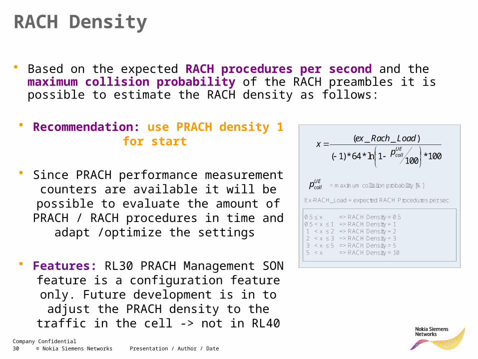
• Based on the expected RACH procedures per second and the maximum collision probability of the RACH preambles it is possible to estimate the RACH density as follows:
100*1001ln*64*)1(
)__(
UEcollpLoadRachexx
UEcollp = maximum collisiion probability [%]
Ex-RACH_Load = expected RACH Procedures per sec
0.5 ≤ x => RACH Density = 0.50.5 < x ≤ 1 => RACH Density = 1 1 < x ≤ 2 => RACH Density = 2 2 < x ≤ 3 => RACH Density = 3 3 < x ≤ 5 => RACH Density = 5 5 < x => RACH Density = 10
• Recommendation: use PRACH density 1 for start
• Since PRACH performance measurement counters are available it will be possible to evaluate the amount of PRACH / RACH
procedures in time and adapt /optimize the settings
• Features: RL30 PRACH Management SON feature is a configuration feature only. Future
development is in to adjust the PRACH density to the traffic in the cell -> not in RL40
31 © Nokia Siemens Networks Presentation / Author / DateCompany Confidential
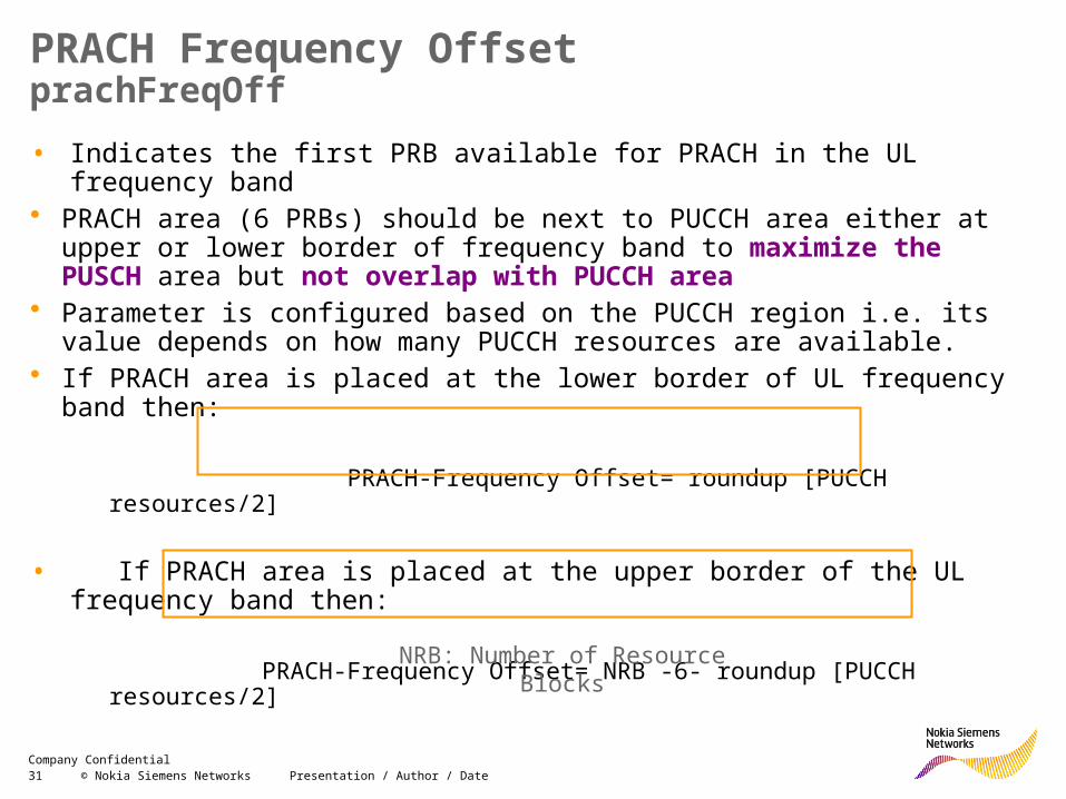
PRACH Frequency OffsetprachFreqOff• Indicates the first PRB available for PRACH in the UL frequency band• PRACH area (6 PRBs) should be next to PUCCH area either at upper or lower
border of frequency band to maximize the PUSCH area but not overlap with PUCCH area
• Parameter is configured based on the PUCCH region i.e. its value depends on how many PUCCH resources are available.
• If PRACH area is placed at the lower border of UL frequency band then:
PRACH-Frequency Offset= roundup [PUCCH resources/2]
• If PRACH area is placed at the upper border of the UL frequency band then:
PRACH-Frequency Offset= NRB -6- roundup [PUCCH resources/2]
• TDD specific: prachFreqOff =0 when preamble format 4 is usedNRB: Number of Resource Blocks
32 © Nokia Siemens Networks Presentation / Author / DateCompany Confidential
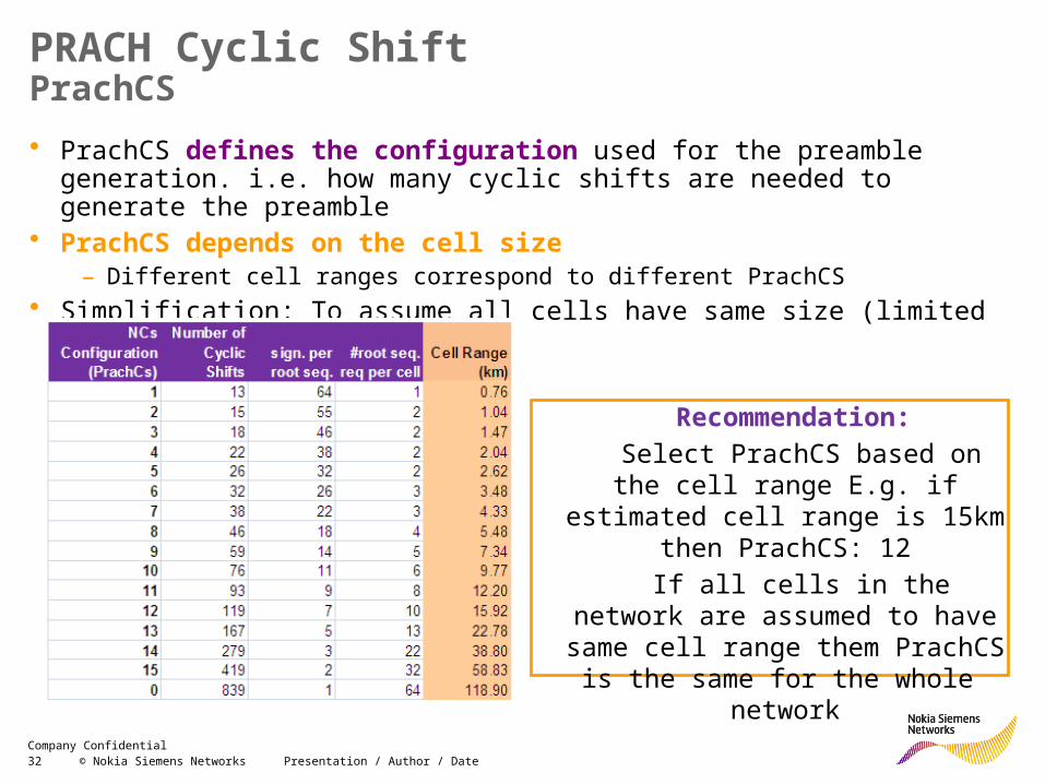
PRACH Cyclic ShiftPrachCS• PrachCS defines the configuration used for the preamble generation. i.e. how
many cyclic shifts are needed to generate the preamble• PrachCS depends on the cell size
– Different cell ranges correspond to different PrachCS• Simplification: To assume all cells have same size (limited by the prachConfIndex)
Recommendation: Select PrachCS based on the cell
range E.g. if estimated cell range is 15km then PrachCS: 12
If all cells in the network are assumed to have same cell range them
PrachCS is the same for the whole network
33 © Nokia Siemens Networks Presentation / Author / DateCompany Confidential
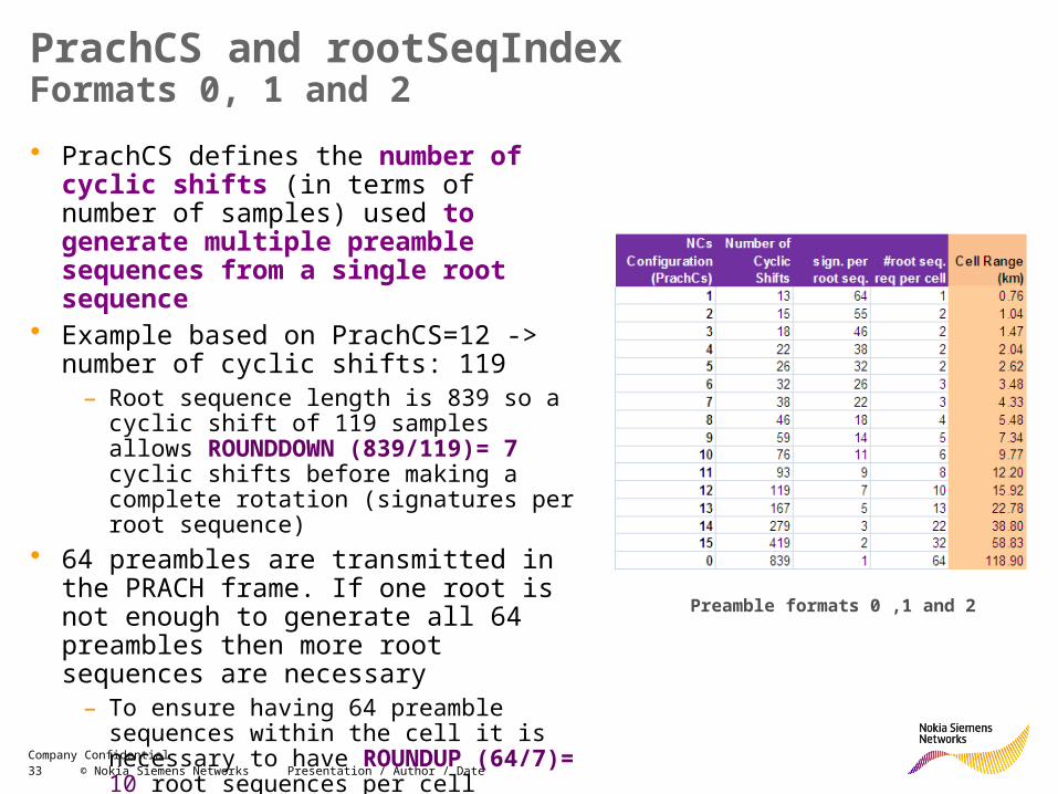
PrachCS and rootSeqIndexFormats 0, 1 and 2• PrachCS defines the number of cyclic
shifts (in terms of number of samples) used to generate multiple preamble sequences from a single root sequence
• Example based on PrachCS=12 -> number of cyclic shifts: 119
– Root sequence length is 839 so a cyclic shift of 119 samples allows ROUNDDOWN (839/119)= 7 cyclic shifts before making a complete rotation (signatures per root sequence)
• 64 preambles are transmitted in the PRACH frame. If one root is not enough to generate all 64 preambles then more root sequences are necessary
– To ensure having 64 preamble sequences within the cell it is necessary to have ROUNDUP (64/7)= 10 root sequences per cell
Preamble formats 0 ,1 and 2
34 © Nokia Siemens Networks Presentation / Author / DateCompany Confidential
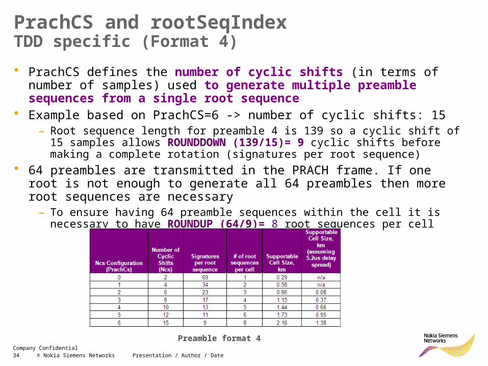
PrachCS and rootSeqIndexTDD specific (Format 4)• PrachCS defines the number of cyclic shifts (in terms of number of samples)
used to generate multiple preamble sequences from a single root sequence
• Example based on PrachCS=6 -> number of cyclic shifts: 15 – Root sequence length for preamble 4 is 139 so a cyclic shift of 15 samples allows
ROUNDDOWN (139/15)= 9 cyclic shifts before making a complete rotation (signatures per root sequence)
• 64 preambles are transmitted in the PRACH frame. If one root is not enough to generate all 64 preambles then more root sequences are necessary
– To ensure having 64 preamble sequences within the cell it is necessary to have ROUNDUP (64/9)= 8 root sequences per cell
Preamble format 4
35 © Nokia Siemens Networks Presentation / Author / DateCompany Confidential
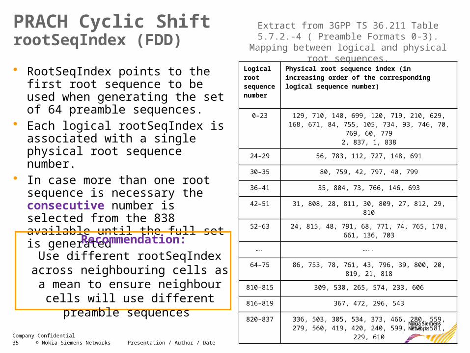
PRACH Cyclic ShiftrootSeqIndex (FDD)
• RootSeqIndex points to the first root sequence to be used when generating the set of 64 preamble sequences.
• Each logical rootSeqIndex is associated with a single physical root sequence number.
• In case more than one root sequence is necessary the consecutive number is selected from the 838 available until the full set is generated
Logical root sequence number
Physical root sequence index (in increasing order of the corresponding logical sequence number)
0–23 129, 710, 140, 699, 120, 719, 210, 629, 168, 671, 84, 755, 105, 734, 93, 746, 70, 769, 60, 779
2, 837, 1, 838
24–29 56, 783, 112, 727, 148, 691
30–35 80, 759, 42, 797, 40, 799
36–41 35, 804, 73, 766, 146, 693
42–51 31, 808, 28, 811, 30, 809, 27, 812, 29, 810
52–63 24, 815, 48, 791, 68, 771, 74, 765, 178, 661, 136, 703
…. …..
64–75 86, 753, 78, 761, 43, 796, 39, 800, 20, 819, 21, 818
810–815 309, 530, 265, 574, 233, 606
816–819 367, 472, 296, 543
820–837 336, 503, 305, 534, 373, 466, 280, 559, 279, 560, 419, 420, 240, 599, 258, 581, 229, 610
Extract from 3GPP TS 36.211 Table 5.7.2.-4 ( Preamble Formats 0-3). Mapping between logical
and physical root sequences.
Recommendation: Use different rootSeqIndex across neighbouring cells as a mean to ensure neighbour cells will use different preamble sequences
36 © Nokia Siemens Networks Presentation / Author / DateCompany Confidential
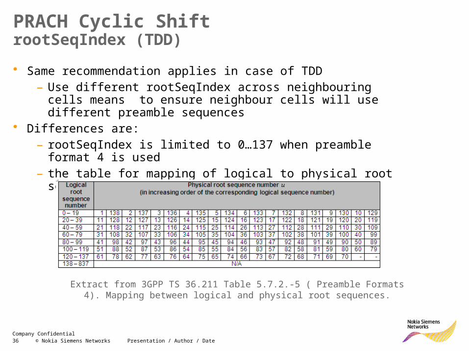
PRACH Cyclic ShiftrootSeqIndex (TDD)
• Same recommendation applies in case of TDD– Use different rootSeqIndex across neighbouring cells means to
ensure neighbour cells will use different preamble sequences • Differences are:
– rootSeqIndex is limited to 0…137 when preamble format 4 is used– the table for mapping of logical to physical root sequence numbers:
Extract from 3GPP TS 36.211 Table 5.7.2.-5 ( Preamble Formats 4). Mapping between logical and physical root sequences.
37 © Nokia Siemens Networks Presentation / Author / DateCompany Confidential
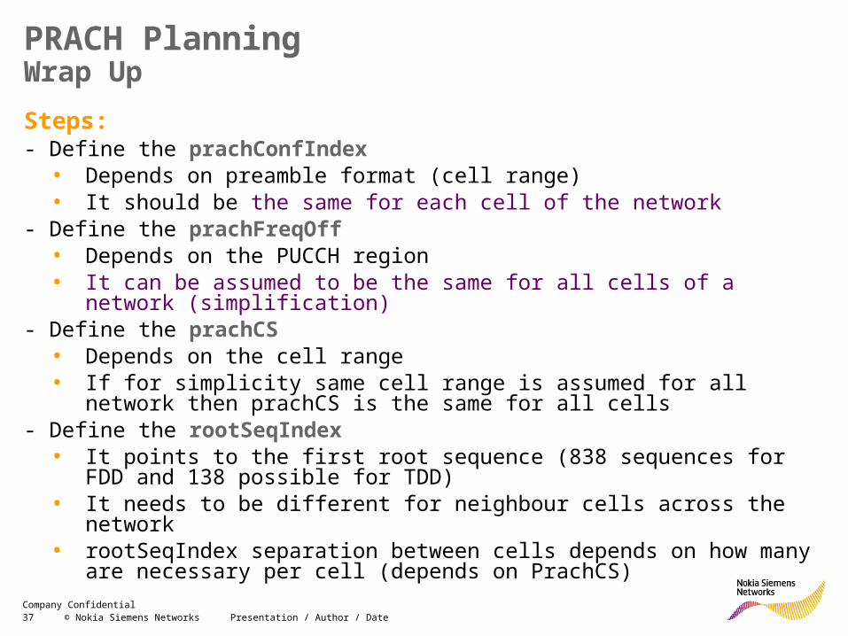
PRACH PlanningWrap UpSteps: - Define the prachConfIndex
• Depends on preamble format (cell range)• It should be the same for each cell of the network
- Define the prachFreqOff• Depends on the PUCCH region• It can be assumed to be the same for all cells of a network (simplification)
- Define the prachCS• Depends on the cell range• If for simplicity same cell range is assumed for all network then prachCS is the
same for all cells- Define the rootSeqIndex
• It points to the first root sequence (838 sequences for FDD and 138 possible for TDD)
• It needs to be different for neighbour cells across the network• rootSeqIndex separation between cells depends on how many are necessary
per cell (depends on PrachCS)
38 © Nokia Siemens Networks Presentation / Author / DateCompany Confidential
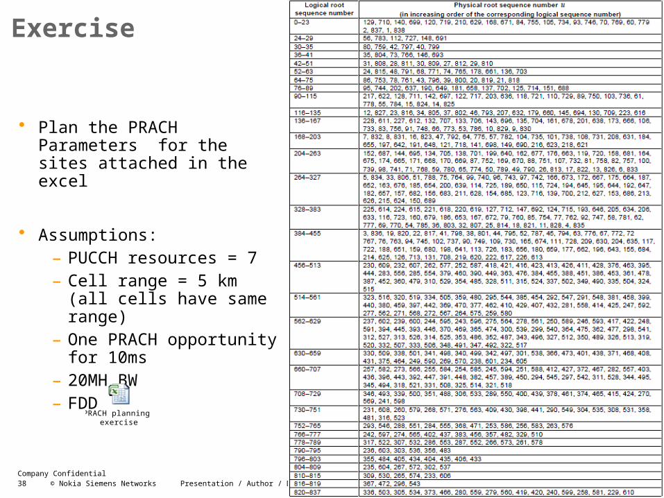
Exercise
• Plan the PRACH Parameters for the sites attached in the excel
• Assumptions:– PUCCH resources = 7– Cell range = 5 km (all cells
have same range)– One PRACH opportunity for
10ms– 20MH BW– FDD
PRACH planning exercise
39 © Nokia Siemens Networks Presentation / Author / DateCompany Confidential
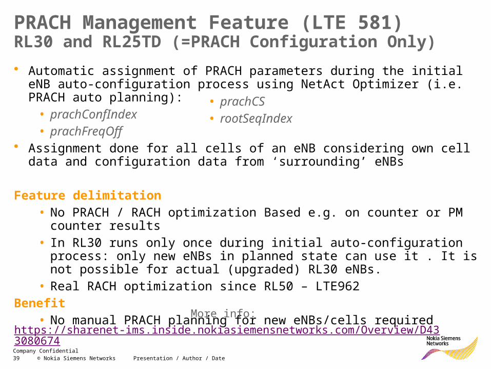
PRACH Management Feature (LTE 581)RL30 and RL25TD (=PRACH Configuration Only)• Automatic assignment of PRACH parameters during the initial eNB auto-
configuration process using NetAct Optimizer (i.e. PRACH auto planning): • prachConfIndex• prachFreqOff
• Assignment done for all cells of an eNB considering own cell data and configuration data from ‘surrounding’ eNBs
Feature delimitation• No PRACH / RACH optimization Based e.g. on counter or PM counter results• In RL30 runs only once during initial auto-configuration process: only new
eNBs in planned state can use it . It is not possible for actual (upgraded) RL30 eNBs.
• Real RACH optimization since RL50 – LTE962Benefit
• No manual PRACH planning for new eNBs/cells requiredMore info:
https://sharenet-ims.inside.nokiasiemensnetworks.com/Overview/D433080674
• prachCS• rootSeqIndex
40 © Nokia Siemens Networks Presentation / Author / DateCompany Confidential
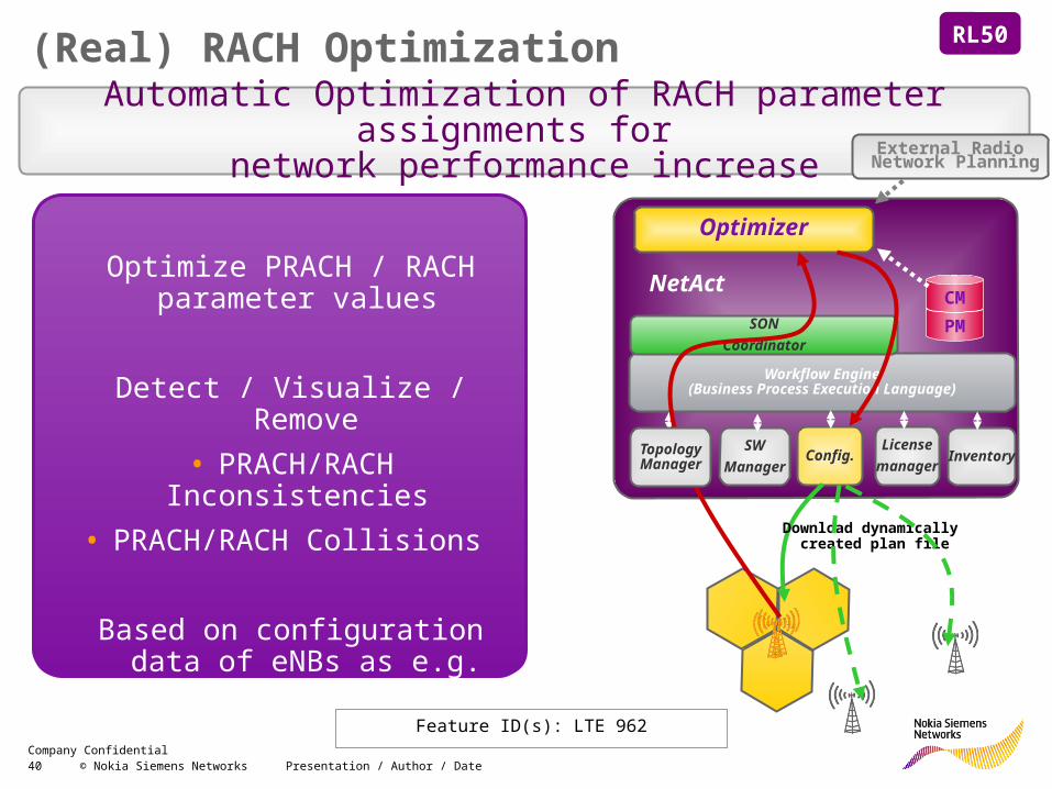
(Real) RACH Optimization
Feature ID(s): LTE 962
RL50
Automatic Optimization of RACH parameter assignments for network performance increase
Optimize PRACH / RACH parameter values
Detect / Visualize / Remove• PRACH/RACH Inconsistencies
• PRACH/RACH Collisions
Based on configuration data of eNBs as e.g. geo-location
Workflow Engine(Business Process Execution Language)
Optimizer
SWManager
Config.Licensemanager Inventory
SONCoordinator
NetActPMCM
TopologyManager
Download dynamically created plan file
External Radio Network Planning

41 © Nokia Siemens Networks Presentation / Author / DateCompany Confidential
- UlseqHop- UlGrpHop- grpAssigPUSCH- ulRsCs- Sequence Group Number (u)
UL Reference Signal Planning
42 © Nokia Siemens Networks Presentation / Author / DateCompany Confidential
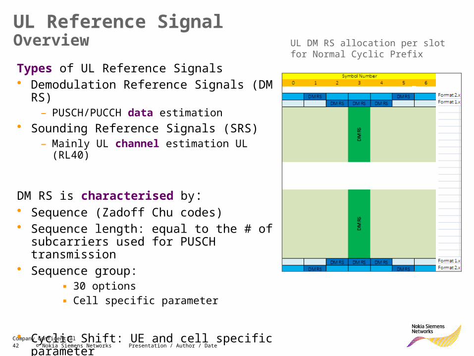
UL Reference SignalOverviewTypes of UL Reference Signals• Demodulation Reference Signals (DM RS)
– PUSCH/PUCCH data estimation• Sounding Reference Signals (SRS)
– Mainly UL channel estimation UL (RL40)
DM RS is characterised by:• Sequence (Zadoff Chu codes)• Sequence length: equal to the # of subcarriers
used for PUSCH transmission• Sequence group:
▪ 30 options▪ Cell specific parameter
• Cyclic Shift: UE and cell specific parameter
UL DM RS allocation per slot for Normal Cyclic Prefix
43 © Nokia Siemens Networks Presentation / Author / DateCompany Confidential
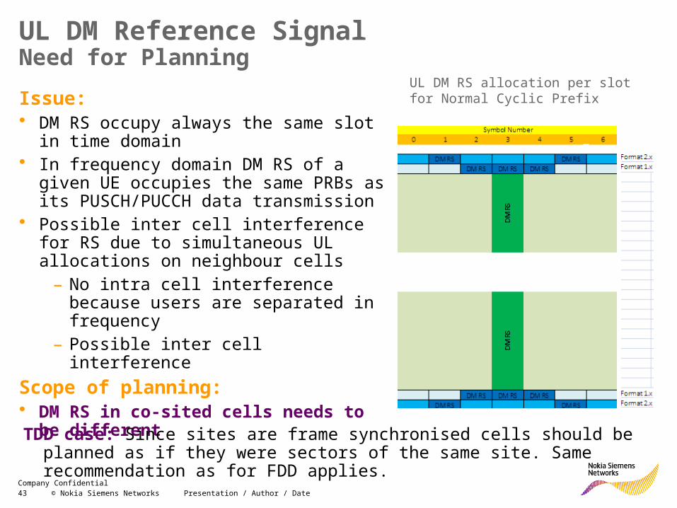
UL DM Reference SignalNeed for PlanningIssue: • DM RS occupy always the same slot in time
domain• In frequency domain DM RS of a given UE
occupies the same PRBs as its PUSCH/PUCCH data transmission
• Possible inter cell interference for RS due to simultaneous UL allocations on neighbour cells
– No intra cell interference because users are separated in frequency
– Possible inter cell interferenceScope of planning: • DM RS in co-sited cells needs to be
different
UL DM RS allocation per slot for Normal Cyclic Prefix
TDD case: Since sites are frame synchronised cells should be planned as if they were sectors of the same site. Same recommendation as for FDD applies.
45 © Nokia Siemens Networks Presentation / Author / DateCompany Confidential
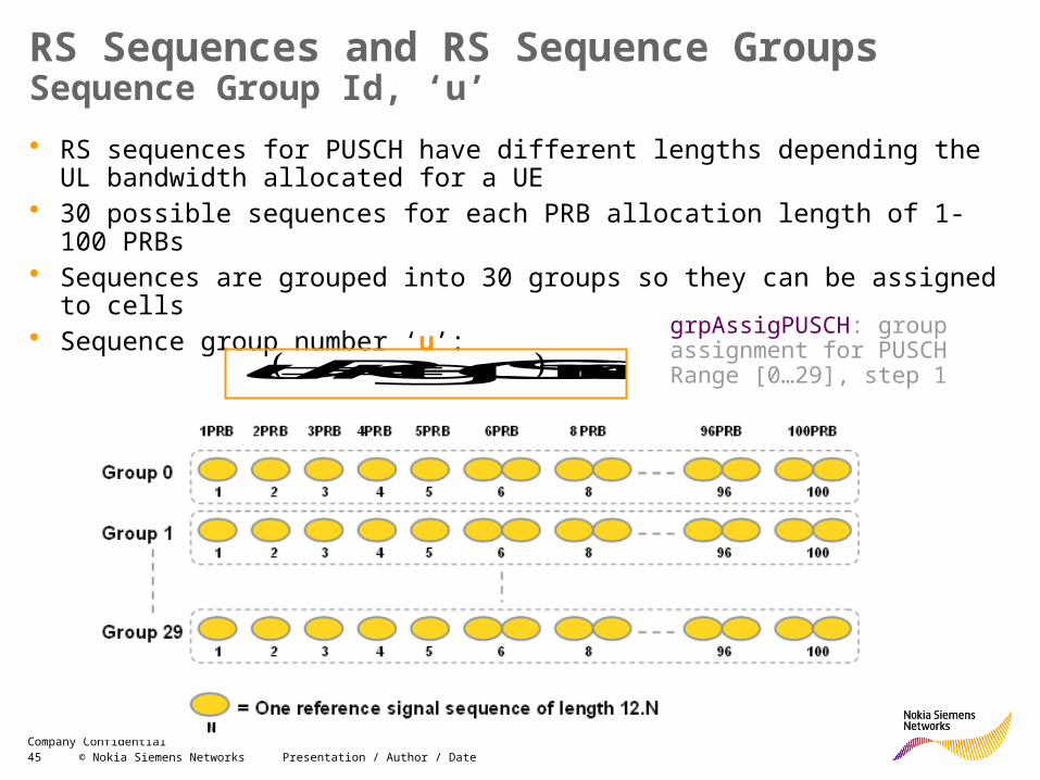
• RS sequences for PUSCH have different lengths depending the UL bandwidth allocated for a UE
• 30 possible sequences for each PRB allocation length of 1-100 PRBs• Sequences are grouped into 30 groups so they can be assigned to cells• Sequence group number ‘u’:
RS Sequences and RS Sequence Groups Sequence Group Id, ‘u’
30modSCHgrpAssigPU PCIu
grpAssigPUSCH: group assignment for PUSCH Range [0…29], step 1
46 © Nokia Siemens Networks Presentation / Author / DateCompany Confidential
Cyclic Shift
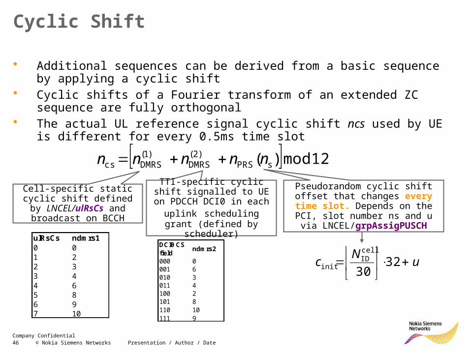
• Additional sequences can be derived from a basic sequence by applying a cyclic shift
• Cyclic shifts of a Fourier transform of an extended ZC sequence are fully orthogonal
• The actual UL reference signal cyclic shift ncs used by UE is different for every 0.5ms time slot
12mod)( sPRS)2(
DMRS)1(
DMRScs nnnnn
Cell-specific static cyclic shift defined by LNCEL/ulRsCs and broadcast on BCCH
TTI-specific cyclic shift signalled to UE on PDCCH
DCI0 in each uplink scheduling grant (defined by
scheduler)
Pseudorandom cyclic shift offset that changes every time slot. Depends
on the PCI, slot number ns and u via LNCEL/grpAssigPUSCH
ulRsCs ndmrs10 01 22 33 44 65 86 97 10
DCI0 CS field ndmrs2
000 0001 6010 3011 4100 2101 8110 10111 9
uNc
32
30
cellID
init
47 © Nokia Siemens Networks Presentation / Author / DateCompany Confidential
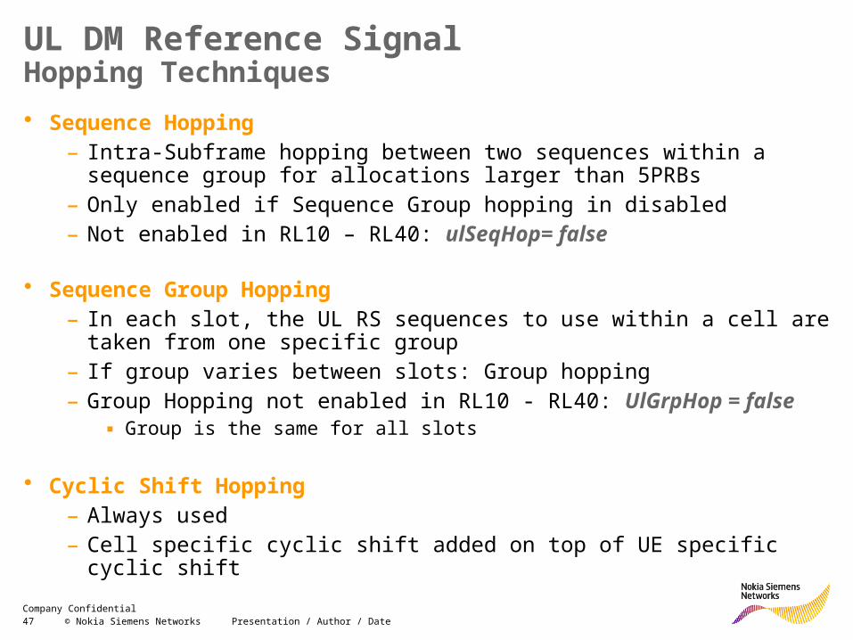
UL DM Reference SignalHopping Techniques• Sequence Hopping
– Intra-Subframe hopping between two sequences within a sequence group for allocations larger than 5PRBs
– Only enabled if Sequence Group hopping in disabled– Not enabled in RL10 – RL40: ulSeqHop= false
• Sequence Group Hopping– In each slot, the UL RS sequences to use within a cell are taken from one
specific group– If group varies between slots: Group hopping– Group Hopping not enabled in RL10 - RL40: UlGrpHop = false
▪ Group is the same for all slots
• Cyclic Shift Hopping– Always used– Cell specific cyclic shift added on top of UE specific cyclic shift
48 © Nokia Siemens Networks Presentation / Author / DateCompany Confidential
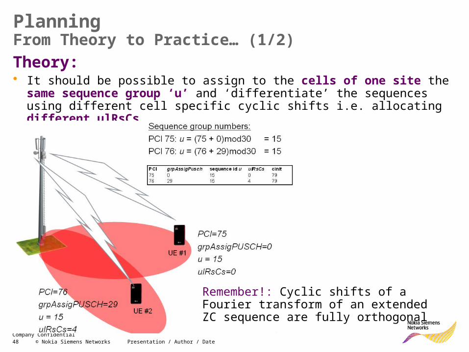
PlanningFrom Theory to Practice… (1/2)Theory: • It should be possible to assign to the cells of one site the same sequence
group ‘u’ and ‘differentiate’ the sequences using different cell specific cyclic shifts i.e. allocating different ulRsCs
Remember!: Cyclic shifts of a Fourier transform of an extended ZC sequence are fully orthogonal
49 © Nokia Siemens Networks Presentation / Author / DateCompany Confidential
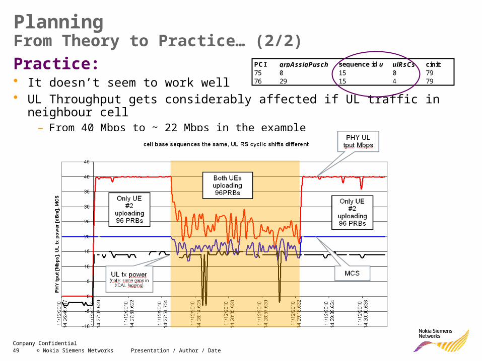
PlanningFrom Theory to Practice… (2/2)Practice: • It doesn’t seem to work well• UL Throughput gets considerably affected if UL traffic in neighbour cell
– From 40 Mbps to ~ 22 Mbps in the example
PCI grpAssigPusch sequence id u ulRsCs cinit75 0 15 0 7976 29 15 4 79
50 © Nokia Siemens Networks Presentation / Author / DateCompany Confidential
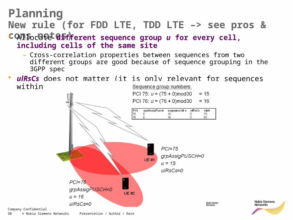
PlanningNew rule (for FDD LTE, TDD LTE –> see pros & cons notes)• Allocate different sequence group u for every cell, including cells of the
same site– Cross-correlation properties between sequences from two different groups are good
because of sequence grouping in the 3GPP spec• ulRsCs does not matter (it is only relevant for sequences within one seq group u)
51 © Nokia Siemens Networks Presentation / Author / DateCompany Confidential
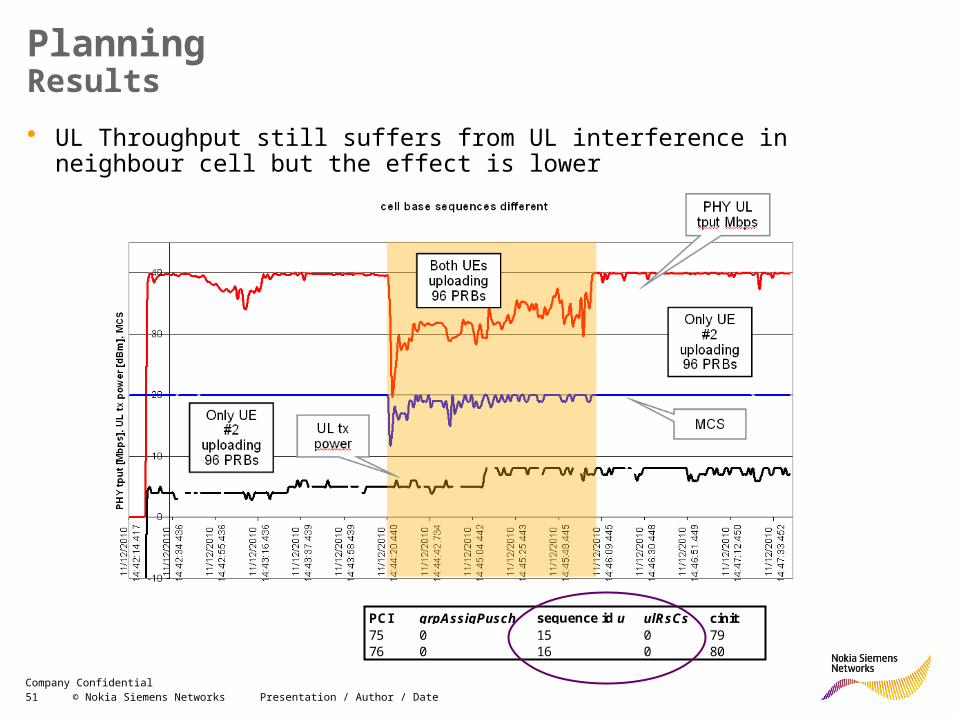
Planning Results• UL Throughput still suffers from UL interference in neighbour cell but the effect is
lower
PCI grpAssigPusch sequence id u ulRsCs cinit75 0 15 0 7976 0 16 0 80
52 © Nokia Siemens Networks Presentation / Author / DateCompany Confidential
Pros an cons of the ‘new’ planning rule
• [+]: Results seem to be better• [+]: Less parameters to plan, only PCI planning needed
– UlRsCs only relevant when using sequences of the same group– ‘u’ will be different if PCI modulo 3 rule is followed. In that case
‘grpAssigPUSCH’ value is not relevant
• [-]: Reduced group reuse distance compared to the case of assigning the same group per each site. This could be source of problem at dense TDD network which is synchronous.
– The case might require either to use old planning rule (same ‘u’ per site and different UlRsCs per cells of the site) or
– Combine new planning rule (different ‘u’ per cells of the site) along with UlRsCs management of neighboring sites.
30modSCHgrpAssigPU PCIu
53 © Nokia Siemens Networks Presentation / Author / DateCompany Confidential
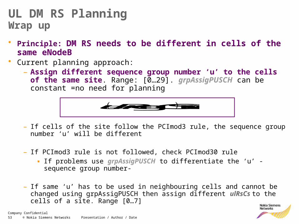
UL DM RS PlanningWrap up
– If cells of the site follow the PCImod3 rule, the sequence group number ‘u’ will be different
– If PCImod3 rule is not followed, check PCImod30 rule ▪ If problems use grpAssigPUSCH to differentiate the ‘u’ - sequence group
number-
– If same ‘u’ has to be used in neighbouring cells and cannot be changed using grpAssigPUSCH then assign different ulRsCs to the cells of a site. Range [0…7]
• Principle: DM RS needs to be different in cells of the same eNodeB• Current planning approach:
– Assign different sequence group number ‘u’ to the cells of the same site. Range: [0…29]. grpAssigPUSCH can be constant =no need for planning
30modSCHgrpAssigPU PCIu
54 © Nokia Siemens Networks Presentation / Author / DateCompany Confidential
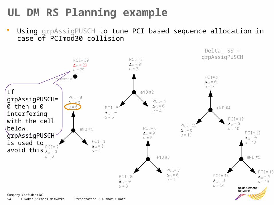
UL DM RS Planning example• Using grpAssigPUSCH to tune PCI based sequence allocation in case of
PCImod30 collision
Delta_ SS = grpAssigPUSCH
PCI = 1Dss = 0u = 1
eNB #1
eNB #2
eNB #3
eNB #4
eNB #5
PCI = 0Dss = 0u = 0
PCI = 2Dss = 0u = 2
PCI = 3Dss = 0u = 3
PCI = 4Dss = 0u = 4
PCI = 5Dss = 0u = 5
PCI = 9Dss = 0u = 9
PCI = 10Dss = 0u = 10
PCI = 11Dss = 0u = 11 PCI = 12
Dss = 0u = 12
PCI = 13Dss = 0u = 13
PCI = 14Dss = 0u = 14
PCI = 6Dss = 0u = 6
PCI = 7Dss = 0u = 7
PCI = 8Dss = 0u = 8
indoor eNB
PCI = 30Dss = 29u = 29
If grpAssigPUSCH=0 then u=0 interfering with the cell below. grpAssigPUSCH is used to avoid this
55 © Nokia Siemens Networks Presentation / Author / DateCompany Confidential
Tracking Area Planning
56 © Nokia Siemens Networks Presentation / Author / DateCompany Confidential
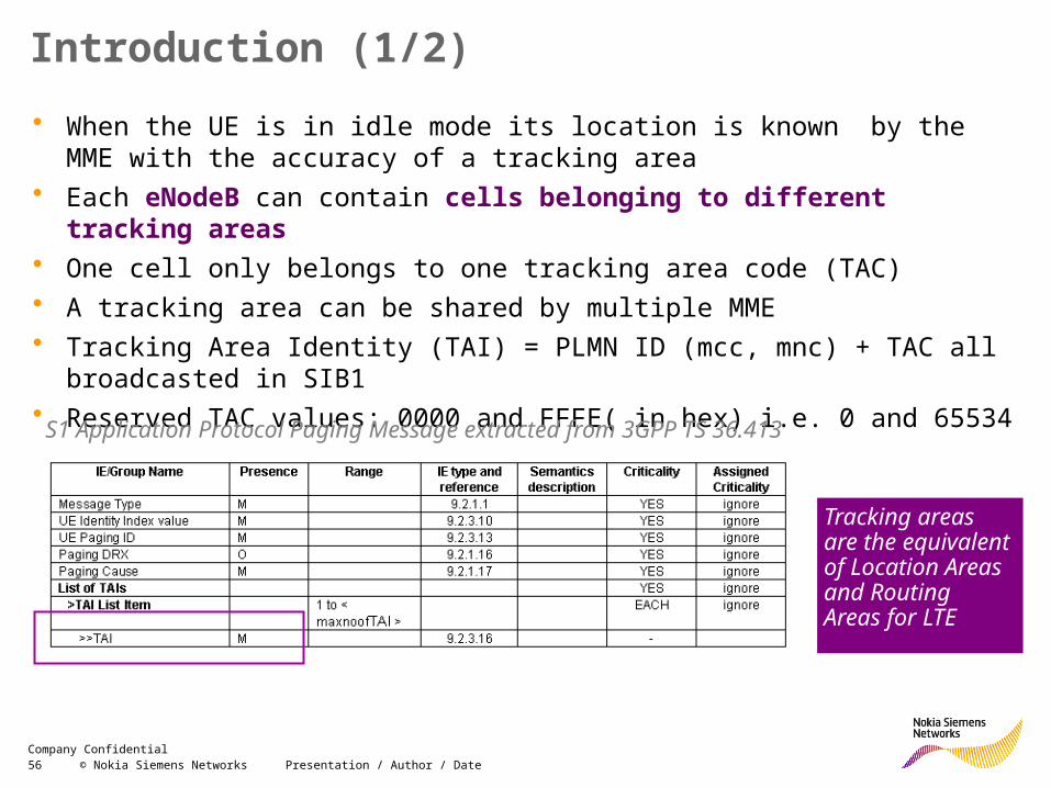
Introduction (1/2)• When the UE is in idle mode its location is known by the MME with the accuracy
of a tracking area• Each eNodeB can contain cells belonging to different tracking areas• One cell only belongs to one tracking area code (TAC)• A tracking area can be shared by multiple MME• Tracking Area Identity (TAI) = PLMN ID (mcc, mnc) + TAC all broadcasted in SIB1• Reserved TAC values: 0000 and FFFE( in hex) i.e. 0 and 65534
S1 Application Protocol Paging Message extracted from 3GPP TS 36.413
Tracking areas are the equivalent of Location Areas and Routing Areas for LTE
57 © Nokia Siemens Networks Presentation / Author / DateCompany Confidential
Introduction (2/2)
• The normal tracking area updating procedure is used when a UE moves into a tracking area within which it is not registered
• The periodic tracking area updating procedure is used to periodically notify the availability of the UE to the network (based upon T3412)
• Tracking area updates are also used for• registration during inter-system changes• MME load balancing
Further details in 3GPP TS 24.301
• Large tracking areas result in• Increased paging load• Reduced requirement for tracking area updates resulting from mobility
58 © Nokia Siemens Networks Presentation / Author / DateCompany Confidential
Planning Guidelines
• Tracking areas should be planned to be relatively large (100 eNodeB, 3 cells/eNodeB) rather than relatively small
• Their size should be reduced subsequently if the paging load > 500 pages/s• TA size impacts MME load. MME have to send messages to each and any eNB
inside the TA. The limitation works in a way more eNB per TA – less users feasible to page at the same time. 100 eNB allows about 60 paged users in parallel
• Tracking areas should not run close to and parallel to major roads nor railways. Likewise, boundaries should not traverse dense subscriber areas
• Cells which are located at a tracking area boundary and which experience large numbers of updates should be monitored to evaluate the impact of the update procedures
• Planning Recommendation: Use different LAC in LTE and 2G/3G (see next slide). This recommendation is aligned with the core planning recommendation and substitutes the old recommendation (only radio planning based) of having the same LAC in LTE and 2G/3G (see notes)
59 © Nokia Siemens Networks Presentation / Author / DateCompany Confidential
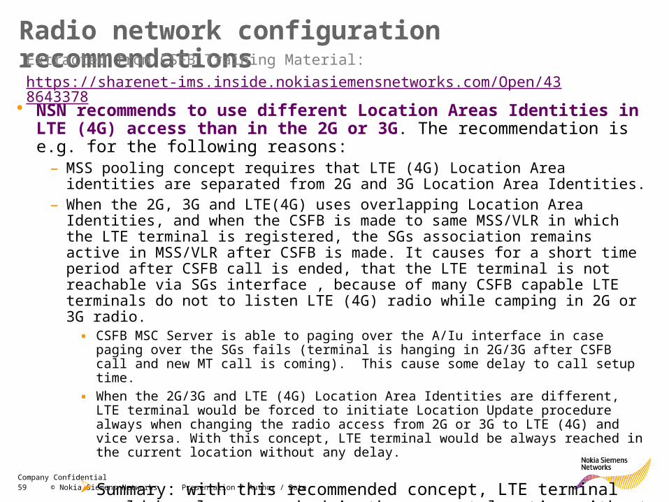
Radio network configuration recommendations
• NSN recommends to use different Location Areas Identities in LTE (4G) access than in the 2G or 3G. The recommendation is e.g. for the following reasons:
– MSS pooling concept requires that LTE (4G) Location Area identities are separated from 2G and 3G Location Area Identities.
– When the 2G, 3G and LTE(4G) uses overlapping Location Area Identities, and when the CSFB is made to same MSS/VLR in which the LTE terminal is registered, the SGs association remains active in MSS/VLR after CSFB is made. It causes for a short time period after CSFB call is ended, that the LTE terminal is not reachable via SGs interface , because of many CSFB capable LTE terminals do not to listen LTE (4G) radio while camping in 2G or 3G radio.
▪ CSFB MSC Server is able to paging over the A/Iu interface in case paging over the SGs fails (terminal is hanging in 2G/3G after CSFB call and new MT call is coming). This cause some delay to call setup time.
▪ When the 2G/3G and LTE (4G) Location Area Identities are different, LTE terminal would be forced to initiate Location Update procedure always when changing the radio access from 2G or 3G to LTE (4G) and vice versa. With this concept, LTE terminal would be always reached in the current location without any delay.
Summary: with this recommended concept, LTE terminal would be always reached in the current location without any delay.
Extracted from CSFB Training Material: https://sharenet-ims.inside.nokiasiemensnetworks.com/Open/438643378
60 © Nokia Siemens Networks Presentation / Author / DateCompany Confidential
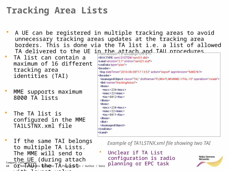
Tracking Area Lists
• A UE can be registered in multiple tracking areas to avoid unnecessary tracking areas updates at the tracking area borders. This is done via the TA list i.e. a list of allowed TA delivered to the UE in the attach and TAU procedures
• TA list can contain a maximum of 16 different tracking area identities (TAI)
• MME supports maximum 8000 TA lists
• The TA list is configured in the MME TA1LSTNX.xml file
• If the same TAI belongs to multiple TA Lists. The MME will send to the UE (during attach or TAU) the TA List with lowest value
Example of TA1LSTNX.xml file showing two TAI
• Unclear if TA List configuration is radio planning or EPC task
61 © Nokia Siemens Networks Presentation / Author / DateCompany Confidential
Tracking Area PlanningRAN sharing case• In case of RAN sharing, recommendation of re-using existing LA from 3G/2G is
not valid as TAC is the same for all PLMN Ids
• LNCEL: tac has multiplicity one i.e. no multiple entries possible• LNCEL: furtherPlmndIdL allows up to 5 entries
• Together with primary PLMN ID (LNBTS: mcc, mnc & mncLength) there can be up to 6 PLMN Ids)
• Feature RAN sharing Multi Operator Core Network (MOCN-LTE4) supported initially only 2 PLMNs, however RL40 allows up to 6 PLMNs.