Embed Size (px)
Citation preview

09-11 Dodge 2500 / 3500 4WD 5” Suspension Lift
Installation Instructions
RequIReD TooL LIST:
* Safety Glasses* Metric / Standard Wrenches & Sockets* Drill & Assorted Drill Bits* Floor Jack* Jack Stands* Measuring Tape* Torque Wrench* Pitman Arm Puller
www.skyjacker.com
I-D4519 REV2 12-10 Pg 1
Before beginning the installation, thoroughly & completely read these instructions & the enclosed driver’s WARNING NOTICE. Affix the WARNING decal in the passenger compartment in clear view of all occupants. Please refer to the Parts List to insure that all parts & hardware are received prior to the disassembly of the vehicle. If any parts are found to be missing, contact SKYJACKER® Customer Service at 318-388-0816 to obtain the needed items. If you have any questions or reservations about installing this lift kit, call SKYJACKER® Technical Assistance at 318-388-0816.
Make sure you park the vehicle on a level concrete or asphalt surface. Many times a vehicle is not level (side-to-side) from the factory & is usually not noticed until a lift kit has been installed, which makes the difference more visible. Using a measuring tape, measure the front & rear (both sides) from the ground up to the center of the fender opening above the axle. Record this information below for future reference.
Driver Side Front: Passenger Side Front:
Driver Side Rear: Passenger Side Rear:
IMPoRTANT NoTeS: • This lift is determined from the amount of lift to the front of the vehicle, while only lifting the
rear to a position level with the front. • If larger tires (10% more than the stock diameter) are installed, speedometer recalibration
will be necessary. Contact your local Dodge dealer or an authorized dealer for details.
• After installation a qualified alignment facility is required to align the vehicle to factory specifications.
• If after installation a front driveline vibration occurs, Part # IXR20K must be ordered. It is an indexing ring that rotates the transfer case to improve the driveline angle.

• Some models will come equipped with a larger Sterling rear axle. These models will require a larger rear U-bolt. Order rear U-bolt kit Part # U9B12R.
• Under no circumstances are SKYJACKER® coil springs to be used in conjunction with any type of coil spring tower, block, or spacer. The use of a coil spring tower, block, or spacer will allow the coil spring to exceed its designed stress & travel load allowing it to be
overstressed, oversprung, fatigued, & possibly broken. The SKYJACKER® warranty is void under any such application.
• For vehicles with a carrier bearing on the rear driveshaft, lowering brackets are available if a rear driveline vibration occurs. (Part # CBL3401 = 1" Drop & Part # CBL214 = 2 1/4" Drop)
I-D4519 Pg 2
Kit Box Breakdown:Part #: D45510 / D45529 ITEM# DESCRIPTION QTY
DUL253-L 03 DGE UPPER LINK 2-5"LIFT 2DLL45-L DODGE LWR LINK 4-5" 2DULRB3-B 03 DGE UPPER LINK RELOC BRK 2DTB50-B (D45510 Box) 10 DGE TRK BAR DROP BRKT,5" 1DTB53-B (D45529 Box) 03 DGE TRK BAR DROP BRKT,5" 1SBL20-L 2.5" SWAY BAR LWG BRKT-LEFT 1SBL20-R 2.5"SWAY BAR LWG BRKT-RIGHT 1DA309 2009 DODGE DROP PITMAN ARM 1BP60S BUMP STOP DODGE RAM 4-5" 2HB-D45510-LK (D45510 Box) HDWR BAG:5"2010 DGE LWR LKS 1HB-D4510-LK (D45529 Box) HDWR BAG: 5" DGE LWR LK 1HB-D4552-LK (D45529 Box) HDWR BAG/4-5" 2000 DODGE L 1HB-D4513-ULB HDWR BAG:UPR LK BRKTS/SBL20 1HB-D4513-BL HDWR BAG/BRAKE LINE BRKTS 1HB-DTB50-TB (D45510 Box) HDWR BAG: DTB50 TRK BAR BRK 1HB-DTB53-TB (D45529 Box) HDWR BAG FOR DTB53 1I-D4519 INSTRUCTION SHEET: D45529 1
Hardware Bag Breakdown:
HB-D45510-LK HARDWARE BAG
ITEM# DESCRIPTION QTY
2617 BUSHING DGE RAM LWR LNK 42618 BUSHING DGE RAM UPPR LNK 8LS20DL LINK SLEEVE,2K LOWER DODGE 2LS20DU LINK SLEEVE,2K UPPER DODGE 4LS2650 LINK SLEEVE 2.65" LOWER 2SP3643 LINK BUSHING DODGE / FORD 4ZF316 ZERK FITTING ALEMITE, 3/16" 8

Pg 3I-D4519
Hardware Bag Breakdown:
HB-D4513-uLB HARDWARe BAG
ITEM# DESCRIPTION QTY
916X5FTB 9/16 X 5 FINE THRD BOLT 2716X112FTB 7/16 X 1 1/2 FINE THRD BOLT 12LS20DU LINK SLEEVE,2K UPPER DODGE 2916FTN 9/16-18 NYLON INSERT LOCKNU 2716FTN 7/16-20 FINE N/I LOCK NUT 12916SAEW 9/16 SAE WASHERS 5716SAEW 7/16 SAE WASHER 24916X6FTB 9/16 X 6 FINE THRD BOLT 112USSW 1/2 USS WASHER 1916STVFTN 9/16-18 STOVER NUT,GRADE C 1
Hardware Bag Breakdown:
HB-D4513-BL HARDWARe BAG
ITEM# DESCRIPTION QTY
DBE23 BRAKE LINE BRKT,03 2500 DGE 2516X1FTB 5/16 X 1 FINE THRD BOLT 2516FTN 5/16" FINE THRD N/I LOCKNUT 2516SAEW 5/16 SAE WASHER 4
Hardware Bag Breakdown:
HB-D4552-LK HARDWARE BAG
ITEM# DESCRIPTION QTY
2617 BUSHING DGE RAM LWR LNK 82618 BUSHING DGE RAM UPPR LNK 8LS20DU LINK SLEEVE,2K UPPER DODGE 4LS20DL LINK SLEEVE,2K LOWER DODGE 4ZF316 ZERK FITTING ALEMITE, 3/16" 8
Hardware Bag Breakdown:
HB-D4510-LK HARDWARE BAG
ITEM# DESCRIPTION QTY
SP3643 LINK BUSHING,LOWER 4LS2650 LINK SLEEVE 2.65" LOWER 2

I-D4519 Pg 4
Hardware Box Breakdown:
H-BOX D4513 HARDWARE BOX
ITEM# DESCRIPTION QTY
WSP334S WEDGE SHIM PLATE FOR R334S 21206 1/2 X 6 TIE BOLTS PR W/NUTS 2916X312X11U 9/16 X 3 1/2 X 11 U-BOLT RD 47013 OEM STABILIZER,03 DODGE 1HB-916 HDWR BAG/ 8 - 9/16" NYLON 1
Hardware Bag Breakdown:
1206 HARDWARe BAG
ITEM# DESCRIPTION QTY
1206S 1/2 X 6 TIE BOLT 212TBN 1/2" TIE BOLT NUT 2
Part #: D4513 (Kit Box) ITEM# DESCRIPTION QTY
R334S ADD-A-LEAF,2003 DGE 3/4 4" 2H-BOX D4513 HDWR BOX: D4513 COMP BOX 1
Hardware Bag Breakdown:
HB-DTB50-TB HARDWARe BAG
ITEM# DESCRIPTION QTY
12X412FTB 1/2 X 4 1/2 FINE THD GRD. 8 112SAEW 1/2 SAE WASHER 212STVFTN 1/2" STOVER LKNUT, FINE THD 158X312FTB 5/8 X 3 1/2 FINE THD BLT,G8 158FTN 5/8-18 NYLON INSERT LOCKNUT 158SAEW 5/8 SAE WASHERS 2
Hardware Bag Breakdown:
HB-DTB53-TB HARDWARe BAG
ITEM# DESCRIPTION QTY
916X3FTB 9/16 X 3 FINE THREAD BOLT 112X412FTB 1/2 X 4 1/2 FINE THD GRD. 8 1916SAEW 9/16 SAE WASHERS 212SAEW 1/2 SAE WASHER 2916FTN 9/16-18 NYLON INSERT LOCKNU 112STVFTN 1/2" STOVER LKNUT, FINE THD 1
Hardware Bag Breakdown:
HB-7013 HARDWARe BAG
ITEM# DESCRIPTION QTY
HOURGLASS 5/8 HOURGLASS 5/8 SHOCK BUSHING 2142121 ES24 SLEEVE/402087 1.38" 1141509 ES25 SLEEVE/403646 1.50" 158SP 5/8" SPACER - 1 1/4" O.D. 112X5FTB 1/2 X 5 FINE THREAD BOLT/G8 112FTN 1/2-20 FINE N/I LOCK NUT 181004 TAPERED SLEEVE, 1/2"I.D. 112SAEW 1/2 SAE WASHER 112USSW 1/2 USS WASHER 1
Hardware Bag Breakdown:
HB-916 HARDWARe BAG
ITEM# DESCRIPTION QTY
916FTN 9/16-18 NYLON INSERT LOCKNU 8
Part #: D4513S (System Box) ITEM# DESCRIPTION QTY 916X312X11U 9/16 X 3 1/2 X 11 U-BOLT RD 47013 OEM STABILIZER,03 DODGE 1HB-916 HDWR BAG/ 8 - 9/16" NYLON 1
I-D4519 Pg 5
Part #: 7013 ITEM# DESCRIPTION QTY
7000WS WHITE STEERING DAMPER 1HB-7013 HARDWARE BAG FOR 7013 1HSS HYDRO SHOCK DECAL 1B10RS RED BOOT 1BTIE RED BOOT TIE 1
Part #: 7013 ITEM# DESCRIPTION QTY
7000WS WHITE STEERING DAMPER 1HB-7013 HARDWARE BAG FOR 7013 1HSS HYDRO SHOCK DECAL 1B10RS RED BOOT 1BTIE RED BOOT TIE 1

Hardware Bag Breakdown:
HB-7013 HARDWARe BAG
ITEM# DESCRIPTION QTY
HOURGLASS 5/8 HOURGLASS 5/8 SHOCK BUSHING 2142121 ES24 SLEEVE/402087 1.38" 1141509 ES25 SLEEVE/403646 1.50" 158SP 5/8" SPACER - 1 1/4" O.D. 112X5FTB 1/2 X 5 FINE THREAD BOLT/G8 112FTN 1/2-20 FINE N/I LOCK NUT 181004 TAPERED SLEEVE, 1/2"I.D. 112SAEW 1/2 SAE WASHER 112USSW 1/2 USS WASHER 1
Hardware Bag Breakdown:
HB-916 HARDWARe BAG
ITEM# DESCRIPTION QTY
916FTN 9/16-18 NYLON INSERT LOCKNU 8
I-D4519 Pg 6

Photo #1
Photo #2
Photo #3
Front Installation:
1. Secure & properly block the tires of the vehicle on a level concrete or asphalt surface.
2. Remove the upper shock nuts, retainers, & the three nuts on the upper shock tower brackets.
3. Lift the front of the vehicle & install jack stands under the frame behind the lower link rear brackets.
4. Remove the front tires & brakeline anchor bracket between the upper & lower links behind the coil spring.
5. Loosen the trackbar at the axle housing. Remove the frame end of the track bar from the frame mount & lower it down.
6. Remove the drag link from the pitman arm. Remove the pitman arm from the steering sector using a pitman arm puller. (See Photo # 1) Install the new Skyjacker drop pitman arm using the OEM lock washer & nut. Note: Do not reinstall the drag link to the pitman arm at this time.
7. Loosen the front sway bar bolts at the frame (Do not remove). Disconnect the sway bar end link from the sway bar mount on the axle. (See Photo # 2)
8. Remove the upper shock tower & lower shock bolt. Pull the shock up through the coil spring under the hood.
9. Lower the front axle down until the coil springs become loose & remove the coil spring, rubber isolator, & three-bolt tower ring. (See Photo # 3)
10. Locate the front rubber bump stop mounted on the frame rail behind the coil spring. Remove the bump stop from the pocket by using a large flat screwdriver or similar tool to pry them out. A pair of channel lock pliers can also be used to remove this bump stop by working it back & forth. (See Photo # 4)
11. At the front lower link adjustment cams, mark (with an ink marker, or scribe a mark) the vertical line on the cam & the reinforcement bracket for reference so you can realign the marks after installation. (See Photo # 5)
12. Install the drive-in grease fittings in each end of all the link arms by using a 1/4" socket over the grease fitting. Tap with a hammer until the grease fitting is flush.
I-D4519 Pg 7
Photo #4
Photo #5

13. Install the new Skyjacker poly bushings (Part # 2617) in each end of the larger lower links & (Part # 2618) in the smaller upper links. Be sure to slightly grease them prior to installation. Insert the 2.645" long sleeve in the larger lower links & the 2.375" long sleeve in the smaller upper links. Note: Some 2009 models & all 2010 models use a 18mm lower link bolt at the axle. If your model has this 18mm bolt, use the larger ID poly bushings (Part # SP3643) & 2.65" sleeves (Part # LS2650) to connect the new Skyjacker lower links to the axle. 14. Loosen & remove the upper & lower links from both sides. Replace
the lower links with the new Skyjacker lower links (one side at a time). Note: Do not tighten at this time. Note: On some models with the
Cummings Diesel the upper control arm bolt on the passenger side at the frame will need to be cut off in order to remove. Skyjacker has
provided a 9/16" x 6" fine thread replacement bolt to be used if neccessary.
15. Install the new Skyjacker upper control arm relocation bracket over the OEM bracket on the axle. Install the 9/16" x 5” fine thread bolt, washers, & nut into the OEM mounting hole. Note: Be sure to install the 2.375” crush sleeve on this bolt inside of the OEM bracket. (See Photo # 6)
16. Mark the two additional holes on each side of the bracket & drill using a 15/32” drill bit. Once drilled, install the 7/16" x 1 1/2” fine thread bolts, washers, & nuts. Note: If installing a Skyjacker Dual Shock Kit, be sure to install the bottom dual shock bracket at this time. (See Photo # 7)
17. When installing the new Skyjacker upper links, slide the front eye through the new Skyjacker upper relocation bracket enough to bolt the rear eye in the OEM frame mount. Position & bolt the front eye through the upper relocation bracket using OEM hardware. Note: Do not tighten at this time. Note: Install the upper links with the front eye of the link having the grease fitting pointing out the end & the rear eye of the link having the grease fitting pointing up.
18. Install the new Skyjacker track bar drop bracket into the OEM mount. Attach the bracket to the OEM mounting hole using the OEM hardware. (See Photo # 8)
19. Install the 1/2" x 4 1/2” fine thread bolt, washers, & nut into the bottom of the bracket, up through the OEM mount. (See Photo # 9)
20. To begin the coil spring installation, insert the OEM three-bolt tower ring in place inside the top of the coil spring tower. Start a couple of the nuts to hold the ring in place. Note: Do not tighten at this time. Note: If installing a dual shock kit, it is important to see those instructions at this time.
I-D4519
Photo #6
Pg 8
Photo #7
Photo #8
Photo #9

21. Install the new Skyjacker coil springs by placing the rubber isolator on top of the coil spring & aligning the coil spring so that the end of the bottom wraps are turned to the inside at the center of the axle. Lift up on a jack under the differential until the coil springs are securely in place & keeping a load on them to hold them in place.
22. Attach the new Skyjacker front brake line relocation bracket to the OEM position using the OEM hardware. Attach the OEM brakeline to new Skyjacker relocation bracket using the 5/16" x 1” fine thread bolt, washer, & nut with the washer under the nut. (See Photo # 10)
23. Remove the OEM steering stabilizer from the drag link & axle mount. Install the new Skyjacker steering stabilizer by inserting a poly bushing & steel sleeve into the shaft end of the steering stabilizer. Insert a poly bushing & the shorter sleeve into the body end of the steering stabilizer. Attach the red boot & secure it with the supplied plastic tie. Install the shaft end of the steering stabilizer to the drag link using the supplied hardware. (See Photo # 11) Insert the tapered sleeve into the tapered hole in the tie rod placing the small 1/2" washer on the 1/2" x 5" bolt & install through the drag link hole. Install the 5/8" spacer, the shaft end of the steering stabilizer, the large 1/2" washer, & the 1/2" self locking nut onto the bolt & tighten. Attach the body end of the stabilizer to the OEM mount using the OEM hardware.
24. Take the stud ends of the front sway bar end links & swing them back up to reattach. Remove the two bolts at the frame from each side of the sway bar & lower the bar down. Install the new Skyjacker sway bar lowering brackets with the offset sloping toward the front bumper using the OEM hardware at the top & the 7/16" x 1 1/2” fine threadbolts, washers, & nuts at the bottom. (See Photo # 12)
25. Install the front tires & lower the vehicle to the ground. Attach the drag link to the pitman arm.
26. Place the new Skyjacker poly bump stop in the OEM bump stop pocket. Using leverage against the bottom of the poly bump stop, force the bump stop into place. (See Photo # 13)
27. Raise the track bar & bolt it to the bottom of the new Skyjacker track bar drop bracket using the 9/16" x 3” fine thread bolt, washers, & nut for 2009 models or the 5/8" x 3 1/2” fine thread bolt, washers, & nut for 2010 models. (See Photo # 14) Note: It may be necessary to turn the steering wheel left or right in order to realign the holes when installing the bolt. Tighten the track bar bolt on the passenger side axle housing.
I-D4519 Pg 9
Photo #10
Photo #11
Photo #12
Front of Vehicle
Photo #13
Photo #14
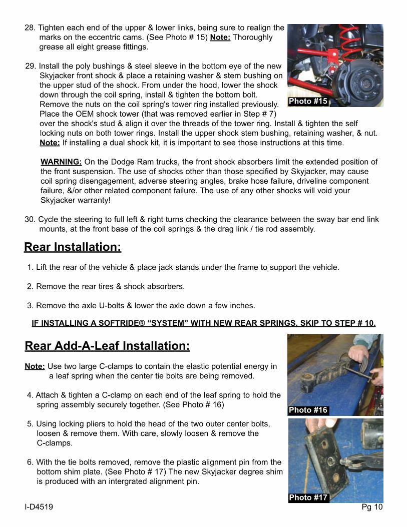
28. Tighten each end of the upper & lower links, being sure to realign the marks on the eccentric cams. (See Photo # 15) Note: Thoroughly grease all eight grease fittings.
29. Install the poly bushings & steel sleeve in the bottom eye of the new Skyjacker front shock & place a retaining washer & stem bushing on the upper stud of the shock. From under the hood, lower the shock down through the coil spring, install & tighten the bottom bolt. Remove the nuts on the coil spring's tower ring installed previously. Place the OEM shock tower (that was removed earlier in Step # 7) over the shock's stud & align it over the threads of the tower ring. Install & tighten the self
locking nuts on both tower rings. Install the upper shock stem bushing, retaining washer, & nut. Note: If installing a dual shock kit, it is important to see those instructions at this time.
WARNING: On the Dodge Ram trucks, the front shock absorbers limit the extended position of the front suspension. The use of shocks other than those specified by Skyjacker, may cause coil spring disengagement, adverse steering angles, brake hose failure, driveline component failure, &/or other related component failure. The use of any other shocks will void your Skyjacker warranty!
30. Cycle the steering to full left & right turns checking the clearance between the sway bar end link mounts, at the front base of the coil springs & the drag link / tie rod assembly.
1. Lift the rear of the vehicle & place jack stands under the frame to support the vehicle.
2. Remove the rear tires & shock absorbers.
3. Remove the axle U-bolts & lower the axle down a few inches.
IF INSTALLING A SOFTRIDE® “SYSTEM” WITH NEW REAR SPRINGS, SKIP TO STEP # 10.
Rear Add-A-Leaf Installation:
Note: Use two large C-clamps to contain the elastic potential energy in a leaf spring when the center tie bolts are being removed.
4. Attach & tighten a C-clamp on each end of the leaf spring to hold the spring assembly securely together. (See Photo # 16)
5. Using locking pliers to hold the head of the two outer center bolts, loosen & remove them. With care, slowly loosen & remove the C-clamps.
6. With the tie bolts removed, remove the plastic alignment pin from the bottom shim plate. (See Photo # 17) The new Skyjacker degree shim is produced with an intergrated alignment pin.
Photo #15
I-D4519 Pg 10
Rear Installation:
Photo #16
Photo #17

I-D4519 Pg 11
7. Insert the new Skyjacker tie bolts through the new Skyjacker axle wedge shim (thick end installs towards the rear bumper), two bottom OEM shim plates, OEM bottom overload leaf, new Skyjacker add-a-leaf, & through the OEM leaf spring pack. (See Photo # 18) Note: Do not use the center tie bolts to draw the leaf spring leaves together. FAILURE OF ANY COMPONENT CAN CAUSE AN
EXPLOSIVE DISASSEMBLY & POSSIBLE INJURY!
8. Place one C-clamp on each side of the center bolts & tighten evenly. Once the C-clamps have drawn the leaves securely together, hold
the center tie bolt heads with locking pliers & torque the nuts to 41 Ft. Lbs.
9. Remove the C-clamps & cut off the excess length of the tie bolts. (Skip to Step # 12)
Rear Leaf Spring Installation:10. Safely support the fuel tank & loosen the vent & fill hoses on the filler neck. Loosen (Do not
remove) the front fuel tank strap bolt. Disconnect & remove the rear bolt & strap. Carefully slide the fuel tank toward the center of the vehicle to acquire sufficient room to access the driver side front spring eye bolt. Remove the spring eye bolts & OEM leaf springs from the vehicle. Note: It will be necessary on the driver side, to pry the gas tank away from the frame allowing more room to remove & reinstall the front OEM leaf spring eye bolt. Do not pry on the gas tank too much or lower it down too much because the fitting at the top may be broken off.
11. Install the new Skyjacker leaf springs with the thick end of the wedge shim towards the rear bumper. Reconnect the rear fuel tank strap & bolt. Tighten the front strap bolt & the vent & fill hoses on the filler neck.
12. Raise the rear axle, aligning the leaf spring pins with the axle housing. (See Photo # 19) Install & tighten the new Skyjacker U-bolts evenly.
13. Install the new Skyjacker rear shock absorbers & rear tires.
14. Remove the jack stands & lower the vehicle to the ground. (See Photo # 20)
Photo #18
Photo #19
Photo #20
Available Accessory:Dual Steering Stabilizer Part # 7239

I-D4519 Pg 12
FINAL NoTeS:
• After the installation is complete, double check that all nuts & bolts are tight. Refer to the following chart below again for the proper torque specifications. (Do not retighten the nuts & bolts where thread lock compound was used.) • With the vehicle placed on the ground, cycle the steering lock to lock & inspect the steering, suspension, brake lines, front & rear drivelines, fuel lines, & wiring harnesses for proper operation, tightness, & adequate clearance.
• Rotate the driveshafts & check for interference at the differential yoke & cardan joint. If necessary, lightly dress the casting(s) &/or U-joint tabs in order to eliminate the binding.
• Have the headlights readjusted to the proper settings. • Have a qualified alignment center realign the front end to the factory specifications. • Retorque all the bolts after the first 100 miles.
Seat Belts Save Lives, Please Wear Your Seat Belt.
TORQUE SPECIFICATIONS
INCH SYSTEMBolt Size Grade 5 Grade 85/16 15 FT LB 20 FT LB3/8 30 FT LB 35 FT LB7/16 45 FT LB 60 FT LB1/2 65 FT LB 90 FT LB9/16 95 FT LB 130 FTLB5/8 135 FT LB 175 FT LB3/4 185 FT LB 280 FT LB
METRIC SYSTEMBolt Size Class 8.8 Class 10.9 6MM 5 FT LB 9 FT LB8MM 18 FT LB 23 FT LB10MM 32 FT LB 45 FT LB12 MM 55 FT LB 75 FT LB14MM 85 FT LB 120 FT LB16MM 130 FT LB 165 FT LB18MM 170 FT LB 240 FT LB
• The above specifications are not to be used when the bolt is being installed with a bushing.