Embed Size (px)
Citation preview
Gensler500 S. FigueroaLos Angeles, CA90071
McCARTHY COOK
06/19/2017
ISSUE FOR CONSTRUCTION - (REVISION)
3RD FLOOR COMMON AREAS
35 N. LAKE ST.PASADENA, CA 91101
05.9
085.
019
3
RD
FLO
OR
CO
MM
ON
AR
EA
S
IS
SU
E F
OR
CO
NS
TR
UC
TIO
N -
(R
EV
ISIO
N)
06/1
9/20
17
McCARTHY COOK35 N. LAKE ST.PASADENA, CA 91101
GENSLER PROJECT NUMBER: 05.9085.019
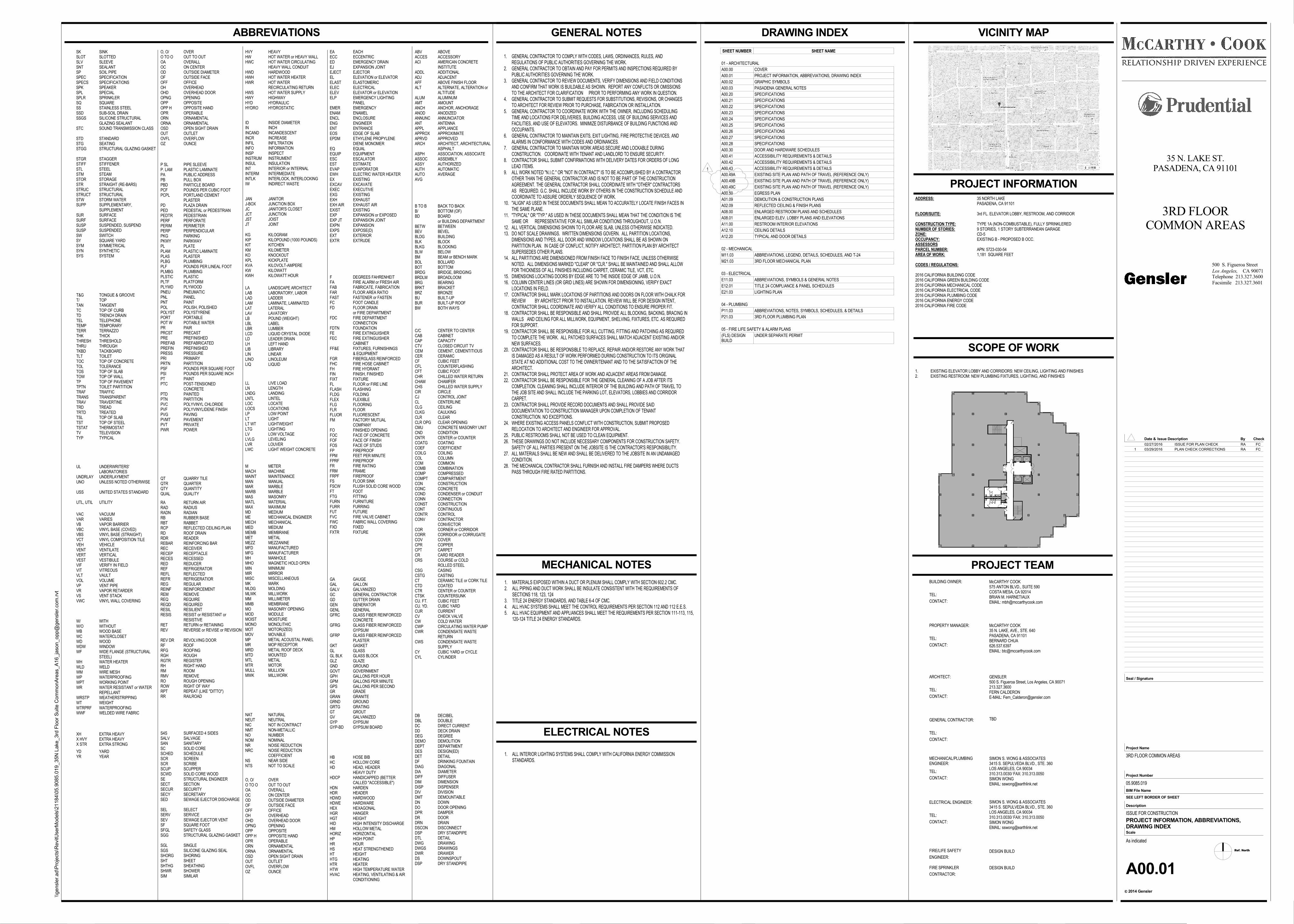
ADDRESS: 35 NORTH LAKEPASADENA, CA 91101
FLOOR/SUITE: 3rd FL. ELEVATOR LOBBY, RESTROOM, AND CORRIDOR
CONSTRUCTION TYPE: TYPE 1A (NON-COMBUSTABLE), FULLY SPRINKLEREDNUMBER OF STORIES: 9 STORIES, 1 STORY SUBTERRANEAN GARAGEZONE: CD-5OCCUPANCY: EXISTING B - PROPOSED B OCC.ASSESSORSPARCEL NUMBER: APN: 5723-030-54AREA OF WORK: 1,181 SQUARE FEET
CODES / REGULATIONS:
2016 CALIFORNIA BUILDING CODE2016 CALIFORNIA GREEN BUILDING CODE2016 CALIFORNIA MECHANICAL CODE2016 CALIFORNIA ELECTRICAL CODE2016 CALIFORNIA PLUMBING CODE2016 CALIFORNIA ENERGY CODE2016 CALIFORNIA FIRE CODE
McCARTHY COOK575 ANTON BLVD., SUITE 590COSTA MESA, CA 92014BRIAN M. HARNETIAUXEMAIL: [email protected]
BUILDING OWNER:
TEL:
CONTACT:
PROPERTY MANAGER:
TEL:
CONTACT:
GENSLER500 S. Figueroa Street, Los Angeles, CA 90071213.327.3600FERN CALDERONE-MAIL: [email protected]
ARCHITECT:
TEL:
CONTACT:
TBDGENERAL CONTRACTOR:
TEL:
CONTACT:
SIMON S. WONG & ASSOCIATES3415 S. SEPULVEDA BLVD., STE. 360LOS ANGELES, CA 90034310.313.0030/ FAX: 310.313.0050SIMON WONGEMAIL: [email protected]
MECHANICAL/PLUMBINGENGINEER:
TEL:
CONTACT:
DESIGN BUILDFIRE/LIFE SAFETY
ENGINEER:
DESIGN BUILDFIRE SPRINKLER
CONTRACTOR:
ELECTRICAL ENGINEER:
TEL:
CONTACT:
McCARTHY COOK35 N. LAKE, AVE., STE. 640PASADENA, CA 91101BERNARD CHUA626.537.6397EMAIL: [email protected]
SIMON S. WONG & ASSOCIATES3415 S. SEPULVEDA BLVD., STE. 360LOS ANGELES, CA 90034310.313.0030/ FAX: 310.313.0050SIMON WONGEMAIL: [email protected]
1. EXISTING ELEVATOR LOBBY AND CORRIDORS: NEW CEILING, LIGHTING AND FINISHES2. EXISTING RESTROOM: NEW PLUMBING FIXTURES, LIGHTING, AND FINISHES
1. GENERAL CONTRACTOR TO COMPLY WITH CODES, LAWS, ORDINANCES, RULES, ANDREGULATIONS OF PUBLIC AUTHORITIES GOVERNING THE WORK.
2. GENERAL CONTRACTOR TO OBTAIN AND PAY FOR PERMITS AND INSPECTIONS REQUIRED BYPUBLIC AUTHORITIES GOVERNING THE WORK.
3. GENERAL CONTRACTOR TO REVIEW DOCUMENTS, VERIFY DIMENSIONS AND FIELD CONDITIONSAND CONFIRM THAT WORK IS BUILDABLE AS SHOWN. REPORT ANY CONFLICTS OR OMISSIONSTO THE ARCHITECT FOR CLARIFICATION PRIOR TO PERFORMING ANY WORK IN QUESTION.
4. GENERAL CONTRACTOR TO SUBMIT REQUESTS FOR SUBSTITUTIONS, REVISIONS, OR CHANGESTO ARCHITECT FOR REVIEW PRIOR TO PURCHASE, FABRICATION OR INSTALLATION.
5. GENERAL CONTRACTOR TO COORDINATE WORK WITH THE OWNER, INCLUDING SCHEDULINGTIME AND LOCATIONS FOR DELIVERIES, BUILDING ACCESS, USE OF BUILDING SERVICES ANDFACILITIES, AND USE OF ELEVATORS. MINIMIZE DISTURBANCE OF BUILDING FUNCTIONS ANDOCCUPANTS.
6. GENERAL CONTRACTOR TO MAINTAIN EXITS, EXIT LIGHTING, FIRE PROTECTIVE DEVICES, ANDALARMS IN CONFORMANCE WITH CODES AND ORDINANCES.
7. GENERAL CONTRACTOR TO MAINTAIN WORK AREAS SECURE AND LOCKABLE DURINGCONSTRUCTION. COORDINATE WITH TENANT AND LANDLORD TO ENSURE SECURITY.
8. CONTRACTOR SHALL SUBMIT CONFIRMATIONS WITH DELIVERY DATES FOR ORDERS OF LONGLEAD ITEMS.
9. ALL WORK NOTED "N.I.C." OR "NOT IN CONTRACT" IS TO BE ACCOMPLISHED BY A CONTRACTOROTHER THAN THE GENERAL CONTRACTOR AND IS NOT TO BE PART OF THE CONSTRUCTIONAGREEMENT. THE GENERAL CONTRACTOR SHALL COORDINATE WITH "OTHER" CONTRACTORSAS REQUIRED. G.C. SHALL INCLUDE WORK BY OTHERS IN THE CONSTRUCTION SCHEDULE ANDCOORDINATE TO ASSURE ORDERLY SEQUENCE OF WORK.
10. "ALIGN" AS USED IN THESE DOCUMENTS SHALL MEAN TO ACCURATELY LOCATE FINISH FACES INTHE SAME PLANE.
11. "TYPICAL" OR "TYP." AS USED IN THESE DOCUMENTS SHALL MEAN THAT THE CONDITION IS THESAME OR REPRESENTATIVE FOR ALL SIMILAR CONDITIONS THROUGHOUT, U.O.N.
12. ALL VERTICAL DIMENSIONS SHOWN TO FLOOR ARE SLAB, UNLESS OTHERWISE INDICATED.13. DO NOT SCALE DRAWINGS. WRITTEN DIMENSIONS GOVERN. ALL PARTITION LOCATIONS,
DIMENSIONS AND TYPES, ALL DOOR AND WINDOW LOCATIONS SHALL BE AS SHOWN ONPARTITION PLAN. IN CASE OF CONFLICT, NOTIFY ARCHITECT; PARTITION PLAN BY ARCHITECTSUPERSEDES OTHER PLANS.
14. ALL PARTITIONS ARE DIMENSIONED FROM FINISH FACE TO FINISH FACE, UNLESS OTHERWISENOTED. ALL DIMENSIONS MARKED "CLEAR" OR "CLR." SHALL BE MAINTAINED AND SHALL ALLOWFOR THICKNESS OF ALL FINISHES INCLUDING CARPET, CERAMIC TILE, VCT, ETC.
15. DIMENSIONS LOCATING DOORS BY EDGE ARE TO THE INSIDE EDGE OF JAMB, U.O.N.16. COLUMN CENTER LINES (OR GRID LINES) ARE SHOWN FOR DIMENSIONING, VERIFY EXACT
LOCATIONS IN FIELD.17. CONTRACTOR SHALL MARK LOCATIONS OF PARTITIONS AND DOORS ON FLOOR WITH CHALK FOR
REVIEW BY ARCHITECT PRIOR TO INSTALLATION. REVIEW WILL BE FOR DESIGN INTENT,CONTRACTOR SHALL COORDINATE AND VERIFY ALL CONDITIONS TO ENSURE PROPER FIT.
18. CONTRACTOR SHALL BE RESPONSIBLE AND SHALL PROVIDE ALL BLOCKING, BACKING, BRACING INWALLS AND CEILING FOR ALL MILLWORK, EQUIPMENT, SHELVING, FIXTURES, ETC. AS REQUIREDFOR SUPPORT.
19. CONTRACTOR SHALL BE RESPONSIBLE FOR ALL CUTTING, FITTING AND PATCHING AS REQUIREDTO COMPLETE THE WORK. ALL PATCHED SURFACES SHALL MATCH ADJACENT EXISTING AND/ORNEW SURFACES.
20. CONTRACTOR SHALL BE RESPONSIBLE TO REPLACE, REPAIR AND/OR RESTORE ANY WORK THATIS DAMAGED AS A RESULT OF WORK PERFORMED DURING CONSTRUCTION TO ITS ORIGINALSTATE AT NO ADDITIONAL COST TO THE OWNER/TENANT AND TO THE SATISFACTION OF THEARCHITECT.
21. CONTRACTOR SHALL PROTECT AREA OF WORK AND ADJACENT AREAS FROM DAMAGE.22. CONTRACTOR SHALL BE RESPONSIBLE FOR THE GENERAL CLEANING OF A JOB AFTER ITS
COMPLETION. CLEANING SHALL INCLUDE INTERIOR OF THE BUILDING AND PATH OF TRAVEL TOTHE JOB SITE AND SHALL INCLUDE THE PARKING LOT, ELEVATORS, LOBBIES AND CORRIDORCARPET.
23. CONTRACTOR SHALL PROVIDE RECORD DOCUMENTS AND SHALL PROVIDE SAIDDOCUMENTATION TO CONSTRUCTION MANAGER UPON COMPLETION OF TENANTCONSTRUCTION. NO EXCEPTIONS.
24. WHERE EXISTING ACCESS PANELS CONFLICT WITH CONSTRUCTION, SUBMIT PROPOSEDRELOCATION TO ARCHITECT AND ENGINEER FOR APPROVAL.
25. PUBLIC RESTROOMS SHALL NOT BE USED TO CLEAN EQUIPMENT.26. THESE DRAWINGS DO NOT INCLUDE NECESSARY COMPONENTS FOR CONSTRUCTION SAFETY.
SAFETY OF ALL PARTIES PRESENT ON THE JOBSITE IS THE CONTRACTOR'S RESPONSIBILITY.27. ALL MATERIALS SHALL BE NEW AND SHALL BE DELIVERED TO THE JOBSITE IN AN UNDAMAGED
CONDITION.28. THE MECHANICAL CONTRACTOR SHALL FURNISH AND INSTALL FIRE DAMPERS WHERE DUCTS
PASS THROUGH FIRE RATED PARTITIONS.
1. MATERIALS EXPOSED WITHIN A DUCT OR PLENUM SHALL COMPLY WITH SECTION 602.2 CMC.2. ALL PIPING AND DUCT WORK SHALL BE INSULATE CONSISTENT WITH THE REQUIREMENTS OF
SECTIONS 118, 123, 1243. TITLE 24 ENERGY STANDARDS, AND TABLE 6-4 OF CMC.4. ALL HVAC SYSTEMS SHALL MEET THE CONTROL REQUIREMENTS PER SECTION 112 AND 112 E.E.S.5. ALL HVAC EQUIPMENT AND APPLIANCES SHALL MEET THE REQUIREMENTS PER SECTION 111-113, 115,
120-124 TITLE 24 ENERGY STANDARDS.
1. ALL INTERIOR LIGHTING SYSTEMS SHALL COMPLY WITH CALIFORNIA ENERGY COMMISSIONSTANDARDS.
C/CCABCAPCTVCEMCERCFCFLCFTCHRCHAMCHSCIRCJCLCLGCLKGCLRCLR OPGCMUCNDCNTRCOATGCOEFCOILGCOLCOMCOMBCOMPCOMPTCONCONCCONDCONNCONSTCONTCONTRCONV
CORCORRCOVCPRCPTCRCRS
CSGCSTGCTCTDCTRCTSKCU. FT.CU. YD.CURCVCWCWPCWR
CWS
CYCYL
CENTER TO CENTERCABINETCAPACITYCLOSED CIRCUIT TVCEMENT, CEMENTITIOUSCERAMICCUBIC FEETCOUNTERFLASHINGCUBIC FOOTCHILLED WATER RETURNCHAMFERCHILLED WATER SUPPLYCIRCLECONTROL JOINTCENTERLINECEILINGCAULKINGCLEARCLEAR OPENINGCONCRETE MASONRY UNITCONDITIONCENTER or COUNTERCOATINGCOEFFICIENTCOILINGCOLUMNCOMMONCOMBINATIONCOMPRESSEDCOMPARTMENTCONSTRUCTIONCONCRETECONDENSER or CONDUITCONNECTIONCONSTRUCTIONCONTINUOUSCONTROLCONTRACTORCONVECTORCORNER or CORRIDORCORRIDOR or CORRUGATECOVERCOPPERCARPETCARD READERCOURSE or COLDROLLED STEELCASINGCASTINGCERAMIC TILE or CORK TILECOATEDCENTER or COUNTERCOUNTERSUNKCUBIC FEETCUBIC YARDCURRENTCHECK VALVECOLD WATERCIRCULATING WATER PUMPCONDENSATE WASTERETURNCONDENSATE WASTESUPPLYCUBIC YARD or CYCLECYLINDER
FFAFABFARFASTFCFD
FDC
FDTNFEFEC
FF&E
FGRFHCFHFINFIXTFLFLASHFLDGFLEXFLGFLRFLUORFM
FOFOCFOFFOSFPFPMFPRFFRFRMFRPFFSFSCWFTFTGFURNFURRFUTFVCFWCFXDFXTR
DEGREES FAHRENHEITFIRE ALARM or FRESH AIRFABRICATE, FABRICATIONFLOOR AREA RATIOFASTENER or FASTENFOOT CANDLEFLOOR DRAINor FIRE DEPARTMENTFIRE DEPARTMENTCONNECTIONFOUNDATIONFIRE EXTINGUISHERFIRE EXTINGUISHERCABINETFIXTURES, FURNISHINGS& EQUIPMENTFIBERGLASS REINFORCEDFIRE HOSE CABINETFIRE HYDRANTFINISH, FINISHEDFIXTUREFLOOR or FIRE LINEFLASHINGFOLDINGFLEXIBLEFLOORINGFLOORFLUORESCENTFACTORY MUTUALCOMPANYFINISHED OPENINGFACE OF CONCRETEFACE OF FINISHFACE OF STUDSFIREPROOFFEET PER MINUTEFIREPROOFFIRE RATINGFRAMEFIREPROOFFLOOR SINKFLUSH SOLID CORE WOODFOOTFITTINGFURNITUREFURRINGFUTUREFIRE VALVE CABINETFABRIC WALL COVERINGFIXEDFIXTURE
HBHCHD
HDCP
HDNHDRHDWDHDWEHEXHGRHGTHIDHMHORIZHPHRHSHTHTGHTRHTWHVAC
HOSE BIBHOLLOW COREHEAD, HEADERHEAVY DUTYHANDICAPPED (BETTERCALLED "ACCESSIBLE")HARDENHEADERHARDWOODHARDWAREHEXAGONALHANGERHEIGHTHIGH INTENSITY DISCHARGEHOLLOW METALHORIZONTALHIGH POINTHOURHEAT STRENGTHENEDHEIGHTHEATINGHEATERHIGH TEMPERATURE WATERHEATING, VENTILATING & AIRCONDITIONING
LANDSCAPE ARCHITECTLABORATORY, LABORLADDERLAMINATE, LAMINATEDLATERALLAVATORYPOUND (WEIGHT)LABELLUMBERLIQUID CRYSTAL DIODELEADER DRAINLEFT HANDLIBRARYLINEARLINOLEUMLIQUID
LALABLADLAMLATLAVLBLBLLBRLCDLDLHLIBLINLINOLIQ
MMACHMAINTMANMARMARBMASMATLMAXMDMEMECHMEDMEMBMETMEZZMFDMFGMHMHOMINMIRMISCMKMLDGMLWKMMMMBMOMODMOISTMONOMOTMOVMPMRMRDMTDMTLMTRMULLMWK
METERMACHINEMAINTENANCEMANUALMARBLEMARBLEMASONRYMATERIALMAXIMUMMEDIUMMECHANICAL ENGINEERMECHANICALMEDIUMMEMBRANEMETALMEZZANINEMANUFACTUREDMANUFACTURERMANHOLEMAGNETIC HOLD OPENMINIMUMMIRRORMISCELLANEOUSMARKMOLDINGMILLWORKMILLIMETERMEMBRANEMASONRY OPENINGMODULEMOISTUREMONOLITHICMOTOR(IZED)MOVABLEMETAL ACOUSTAL PANELMOP RECEPTORMETAL ROOF DECKMOUNTEDMETALMOTORMULLIONMILLWORK
S4SSALVSANSCSCHEDSCRSCRSCUPSCWDSESECTSECURSECYSED
SELSERVSEVSFSFGLSGG
SGLSGSSHORGSHTSHTHGSHWRSIM
SURFACED 4 SIDESSALVAGESANITARYSOLID CORESCHEDULESCREENSCRIBESCUPPERSOLID CORE WOODSTRUCTURAL ENGINEERSECTIONSECURITYSECRETARYSEWAGE EJECTOR DISCHARGE
SELECTSERVICESEWAGE EJECTOR VENTSQUARE FOOTSAFETY GLASSSTRUCTURAL GLAZING GASKET
SINGLESILICONE GLAZING SEALSHORINGSHEETSHEATHINGSHOWERSIMILAR
W/W/OWBWCWDWDWWF
WHWLDWMWPWPTWR
WRSTPWTWTRPRFWWF
WITHWITHOUTWOOD BASEWATERCLOSETWOODWINDOWWIDE FLANGE (STRUCTURALSTEEL)WATER HEATERWELDWIRE MESHWATERPROOFINGWORKING POINTWATER RESISTANT or WATERREPELLANTWEATHERSTRIPPINGWEIGHTWATERPROOFINGWELDED WIRE FABRIC
ABVACCESACI
ADDLADJAFFALT
ALUMAMTANCHANODANNUNCANTAPPLAPPROXAPRVDARCH
ASPHASSOCASSYAUTHAUTOAVG
ABOVEACCESSORYAMERICAN CONCRETEINSTITUTEADDITIONALADJACENTABOVE FINISH FLOORALTERNATE, ALTERATION orALTITUDEALUMINUMAMOUNTANCHOR, ANCHORAGEANODIZEDANNUNCIATORANTENNAAPPLIANCEAPPROXIMATEAPPROVEDARCHITECT, ARCHITECTURALASPHALTASSOCIATION, ASSOCIATEASSEMBLYAUTHORIZEDAUTOMATICAVERAGE
B TO BB/BD
BETWBEVBLDGBLKBLKGBLWBMBOLBOTBRDGBRDLMBRGBRKTBRZBUBURBW
BACK TO BACKBOTTOM (OF)BOARDor BUILDING DEPARTMENTBETWEENBEVELBUILDINGBLOCKBLOCKINGBELOWBEAM or BENCH MARKBOLLARDBOTTOMBRIDGE, BRIDGINGBROADLOOMBEARINGBRACKETBRONZEBUILT-UPBUILT-UP ROOFBOTH WAYS
GAGALGALVGCGDGENGENLGFRC
GFRG
GFRP
GKTGLGL BLKGLZGNDGOVTGPHGPMGPSGRGRANGRNDGRTGGTGVGYPGYP-BD
GAUGEGALLONGALVANIZEDGENERAL CONTRACTORGUTTER DRAINGENERATORGENERALGLASS FIBER REINFORCEDCONCRETEGLASS FIBER REINFORCEDGYPSUMGLASS FIBER REINFORCEDPLASTERGASKETGLASSGLASS BLOCKGLAZEGROUNDGOVERNMENTGALLONS PER HOURGALLONS PER MINUTEGALLONS PER SECONDGRADEGRANITEGROUNDGRATINGGROUTGALVANIZEDGYPSUMGYPSUM BOARD
IDININCANDINCRINFILINFOINSPINSTRUMINSULINTINTERMINTLKIW
INSIDE DIAMETERINCHINCANDESCENTINCREASEINFILTRATIONINFORMATIONINSPECTINSTRUMENTINSULATIONINTERIOR or INTERNALINTERMEDIATEINTERLOCK, INTERLOCKINGINDIRECT WASTE
JANJ-BOXJCJCTJSTJT
JANITORJUNCTION BOXJANITOR'S CLOSETJUNCTIONJOISTJOINT
KGKIPKITKMKOKPLKVAKWKWH
KILOGRAMKILOPOUND (1000 POUNDS)KITCHENKILOMETERKNOCKOUTKICKPLATEKILOVOLT-AMPEREKILOWATTKILOWATT HOUR
LIVE LOADLENGTHLANDINGLINTELLOCATELOCATIONSLOW POINTLIGHTLIGHTWEIGHTLIGHTINGLOW VOLTAGELEVELINGLOUVERLIGHT WEIGHT CONCRETE
LLLNLNDGLNTLLOCLOCSLPLTLT WTLTGLVLVLGLVRLWC
NATNEUTNICNMTNONOMNRNRC
NSNTS
NATURALNEUTRALNOT IN CONTRACTNON-METALLICNUMBERNOMINALNOISE REDUCTIONNOISE REDUCTIONCOEFFICIENTNEAR SIDENOT TO SCALE
P SLP. LAMPAPBPBDPCFPCPL
PDPEDPEDTRPERFPERIMPERPPKGPKWYPLPLAMPLASPLBGPLFPLMBGPLSTICPLTFPLYWDPNEUPNLPNTPOLPOLYSTPORTPOT WPRPRCSTPREPREFABPREFINPRESSPRIPRTNPSFPSIPTPTC
PTDPTNPVCPVFPVGPVMTPVTPWR
PIPE SLEEVEPLASTIC LAMINATEPUBLIC ADDRESSPULL BOXPARTICLE BOARDPOUNDS PER CUBIC FOOTPORTLAND CEMENTPLASTERPLAZA DRAINPEDESTAL or PEDESTRIANPEDESTRIANPERFORATEPERIMETERPERPENDICULARPARKINGPARKWAYPLATEPLASTIC LAMINATEPLASTERPLUMBINGPOUNDS PER LINEAL FOOTPLUMBINGPLASTICPLATFORMPLYWOODPNEUMATICPANELPAINTPOLISH, POLISHEDPOLYSTYRENEPORTABLEPOTABLE WATERPAIRPRECASTPREFINISHEDPREFABRICATEDPREFINISHEDPRESSUREPRIMARYPARTITIONPOUNDS PER SQUARE FOOTPOUNDS PER SQUARE INCHPAINTPOST-TENSIONEDCONCRETEPAINTEDPARTITIONPOLYVINYL CHLORIDEPOLYVINYLIDENE FINISHPAVINGPAVEMENTPRIVATEPOWER
QTQTRQTYQUAL
QUARRY TILEQUARTERQUANTITYQUALITY
RARADRADNRBRBTRCPRDRDRREBARRECRECEPRECESREDREFREFLREFRREGREINFREMREQREQDRESILRESIS
RETREV
REV DRRFRFGRGHRGTRRHRMRMVROROWRPTRR
RETURN AIRRADIUSRADIANRUBBER BASERABBETREFLECTED CEILING PLANROOF DRAINREADERREINFORCING BARRECEIVERRECEPTACLERECESSEDREDUCERREFRIGERATORREFLECTEDREFRIGERATIORREGULARREINFORCEMENTREMOVEREQUIREREQUIREDRESILIENTRESIST or RESISTANT orRESISTIVERETURN or RETAININGREVERSE or REVISE or REVISION
REVOLVING DOORROOFROOFINGROUGHREGISTERRIGHT HANDROOMREMOVEROUGH OPENINGRIGHT OF WAYREPEAT (LIKE "DITTO")RAILROAD
T>/TANTCTDTELTEMPTERRTHKTHRESHTHRUTKBDTLTTOCTOLTOSTOWTPTPTNTRAFTRANSTRAVTRDTRTDTSLTSTTSTATTVTYP
TONGUE & GROOVETOPTANGENTTOP OF CURBTRENCH DRAINTELEPHONETEMPORARYTERRAZZOTHICKTHRESHOLDTHROUGHTACKBOARDTOILETTOP OF CONCRETETOLERANCETOP OF SLABTOP OF WALLTOP OF PAVEMENTTOILET PARTITIONTRAFFICTRANSPARENTTRAVERTINETREADTREATEDTOP OF SLABTOP OF STEELTHERMOSTATTELEVISIONTYPICAL
UL
UNDRLAYUNO
USS
UTL, UTIL
UNDERWRITERS'LABORATORIESUNDERLAYMENTUNLESS NOTED OTHERWISE
UNITED STATES STANDARD
UTILITY
VACVARVBVBCVBSVCTVEHVENTVERTVESTVIFVITVLTVOLVPVRVSVWC
VACUUMVARIESVAPOR BARRIERVINYL BASE (COVED)VINYL BASE (STRAIGHT)VINYL COMPOSITION TILEVEHICLEVENTILATEVERTICALVESTIBULEVERIFY IN FIELDVITREOUSVAULTVOLUMEVENT PIPEVAPOR RETARDERVENT STACKVINYL WALL COVERING
XHX HVYX STR
EXTRA HEAVYEXTRA HEAVYEXTRA STRONG
YDYR
YARDYEAR
DBDBLDCDDDEGDEMODEPTDESDETDFDIAGDIADIFFDIMDISPDIVDMTDNDODPRDRDRNDSCONDSPDTLDWGDWGSDWRDSDSP
DECIBELDOUBLEDIRECT CURRENTDECK DRAINDEGREEDEMOLITIONDEPARTMENTDESIGN(ED)DETAILDRINKING FOUNTAINDIAGONALDIAMETERDIFFUSERDIMENSIONDISPENSERDIVISIONDEMOUNTABLEDOWNDOOR OPENINGDAMPERDOORDRAINDISCONNECTDRY STANDPIPEDETAILDRAWINGDRAWINGSDRAWERDOWNSPOUTDRY STANDPIPE
EACHECCENTRICEMERGENCY DRAINEXPANSION JOINTEJECTORELEVATION or ELEVATORELASTOMERICELECTRICALELEVATOR or ELEVATIONEMERGENCY LIGHTINGPANELEMERGENCYENAMELENCLOSUREENGINEERENTRANCEEDGE OF SLABETHYLENE PROPYLENEDIENE MONOMEREQUALEQUIPMENTESCALATORESTIMATEEVAPORATORELECTRIC WATER HEATEREXISTINGEXCAVATEEXECUTIVEEXISTINGEXHAUSTEXHAUST AIREXISTINGEXPANSION or EXPOSEDEXPANSION JOINTEXPANSIONEXPOSE(D)EXTERIOREXTRUDE
EAECCEDEJEJECTELELASTELECELEVELP
EMERENAMENCLENGENTEOSEPDM
EQEQUIPESCESTEVAPEWHEXEXCAVEXECEXGEXHEXH AIREXISTEXPEXP JTEXPNEXPSEXTEXTR
HVYHWHWC
HWDHWHHWR
HWSHWYHYDHYDRO
HEAVYHOT WATER or HEAVY WALLHOT WATER CIRCULATINGHEAVY WALL CONDUITHARDWOODHOT WATER HEATERHOT WATERRECIRCULATING RETURNHOT WATER SUPPLYHIGHWAYHYDRAULICHYDROSTATIC
O, O/O TO OOAOCODOFOFFOHOHDOPNGOPPOPP HOPRORNORNAOSDOUTOVFLOZ
OVEROUT TO OUTOVERALLON CENTEROUTSIDE DIAMETEROUTSIDE FACEOFFICEOVERHEADOVERHEAD DOOROPENINGOPPOSITEOPPOSITE HANDOPERABLEORNAMENTALORNAMENTALOPEN SIGHT DRAINOUTLETOVERFLOWOUNCE
O, O/O TO OOAOCODOFOFFOHOHDOPNGOPPOPP HOPRORNORNAOSDOUTOVFLOZ
OVEROUT TO OUTOVERALLON CENTEROUTSIDE DIAMETEROUTSIDE FACEOFFICEOVERHEADOVERHEAD DOOROPENINGOPPOSITEOPPOSITE HANDOPERABLEORNAMENTALORNAMENTALOPEN SIGHT DRAINOUTLETOVERFLOWOUNCE
SKSLOTSLVSNTSPSPECSPECSSPKSPLSPLRSQSSSSDSSGS
STC
STDSTGSTGG
STGRSTIFFSTLSTMSTORSTRSTRUCSTRUCTSTWSUPP
SURSURFSUSPSUSPSWSYSYMSYNSYS
SINKSLOTTEDSLEEVESEALANTSOIL PIPESPECIFICATIONSPECIFICATIONSSPEAKERSPECIALSPRINKLERSQUARESTAINLESS STEELSUB-SOIL DRAINSILICONE STRUCTURALGLAZING SEALANTSOUND TRANSMISSION CLASS
STANDARDSEATINGSTRUCTURAL GLAZING GASKET
STAGGERSTIFFENERSTEELSTEAMSTORAGESTRAIGHT (RE-BARS)STRUCTURALSTRUCTURALSTORM WATERSUPPLEMENTARY,SUPPLEMENTSURFACESURFACESUSPENDED, SUSPENDSUSPENDEDSWITCHSQUARE YARDSYMMETRICALSYNTHETICSYSTEM
Ref. North
CA 90071Los Angeles,
2014 Gensler
Project Number
BIM File Name
Scale
Description
c
Project Name
Seal / Signature
Check
Facsimile 213.327.3601
Telephone 213.327.3600
Date & By
500 S. Figueroa Street
Issue Description
SEE LEFT BORDER OF SHEET
\\ge
nsl
er.
ad\P
roje
cts
\RevitU
serM
od
els
\21
184
\05
.90
85.0
19
_35
N L
ake
_3rd
Flo
or
Su
ite C
om
mo
nA
reas_A
16_ja
son_o
pp@
gen
sle
r.com
.rvt
As indicated
35 N. LAKE ST.PASADENA, CA 91101
3RD FLOORCOMMON AREAS
3RD FLOOR COMMON AREAS
05.9085.019
ISSUE FOR CONSTRUCTION
A00.01
PROJECT INFORMATION, ABBREVIATIONS,DRAWING INDEX
SHEET NUMBER SHEET NAME
01 - ARCHITECTURAL
A00.00 COVER
A00.01 PROJECT INFORMATION, ABBREVIATIONS, DRAWING INDEX
A00.02 GRAPHIC SYMBOLS
A00.03 PASADENA GENERAL NOTES
A00.20 SPECIFICATIONS
A00.21 SPECIFICATIONS
A00.22 SPECIFICATIONS
A00.23 SPECIFICATIONS
A00.24 SPECIFICATIONS
A00.25 SPECIFICATIONS
A00.26 SPECIFICATIONS
A00.27 SPECIFICATIONS
A00.28 SPECIFICATIONS
A00.30 DOOR AND HARDWARE SCHEDULES
A00.41 ACCESSIBILITY REQUIREMENTS & DETAILS
A00.42 ACCESSIBILITY REQUIREMENTS & DETAILS
A00.43 ACCESSIBILITY REQUIREMENTS & DETAILS
A00.49A EXISTING SITE PLAN AND PATH OF TRAVEL (REFERENCE ONLY)
A00.49B EXISTING SITE PLAN AND PATH OF TRAVEL (REFERENCE ONLY)
A00.49C EXISTING SITE PLAN AND PATH OF TRAVEL (REFERENCE ONLY)
A00.50 EGRESS PLAN
A01.09 DEMOLITION & CONSTRUCTION PLANS
A02.09 REFLECTED CEILING & FINISH PLANS
A08.00 ENLARGED RESTROOM PLANS AND SCHEDULES
A08.01 ENLARGED ELEV. LOBBY PLANS AND ELEVATIONS
A11.00 RESTROOM INTERIOR ELEVATIONS
A12.10 CEILING DETAILS
A12.20 TYPICAL AND DOOR DETAILS
02 - MECHANICAL
M11.03 ABBREVIATIONS, LEGEND, DETAILS, SCHEDULES, AND T-24
M21.03 3RD FLOOR MECHANICAL PLAN
03 - ELECTRICAL
E11.03 ABBREVIATIONS, SYMBOLS & GENERAL NOTES
E12.01 TITLE 24 COMPLIANCE & PANEL SCHEDULES
E21.03 LIGHTING PLAN
04 - PLUMBING
P11.03 ABBREVIATIONS, NOTES, SYMBOLS, SCHEDULES, & DETAILS
P21.03 3RD FLOOR PLUMBING PLAN
05 - FIRE LIFE SAFETY & ALARM PLANS
(FLS) DESIGNBUILD
UNDER SEPARATE PERMIT
MECHANICAL NOTES
ELECTRICAL NOTES
VICINITY MAP
SCOPE OF WORK
PROJECT INFORMATION
PROJECT TEAM
DRAWING INDEXABBREVIATIONS GENERAL NOTES
1
02/27/2016 ISSUE FOR PLAN CHECK RA FC
1 03/29/2016 PLAN CHECK CORRECTIONS RA FC
Ref. North
CA 90071Los Angeles,
2014 Gensler
Project Number
BIM File Name
Scale
Description
c
Project Name
Seal / Signature
Check
Facsimile 213.327.3601
Telephone 213.327.3600
Date & By
500 S. Figueroa Street
Issue Description
SEE LEFT BORDER OF SHEET
\\ge
nsl
er.
ad\P
roje
cts
\RevitU
serM
od
els
\21
184
\05
.90
85.0
19
_35
N L
ake
_3rd
Flo
or
Su
ite C
om
mo
nA
reas_A
16_ja
son_o
pp@
gen
sle
r.com
.rvt
35 N. LAKE ST.PASADENA, CA 91101
3RD FLOORCOMMON AREAS
3RD FLOOR COMMON AREAS
05.9085.019
ISSUE FOR CONSTRUCTION
A00.02
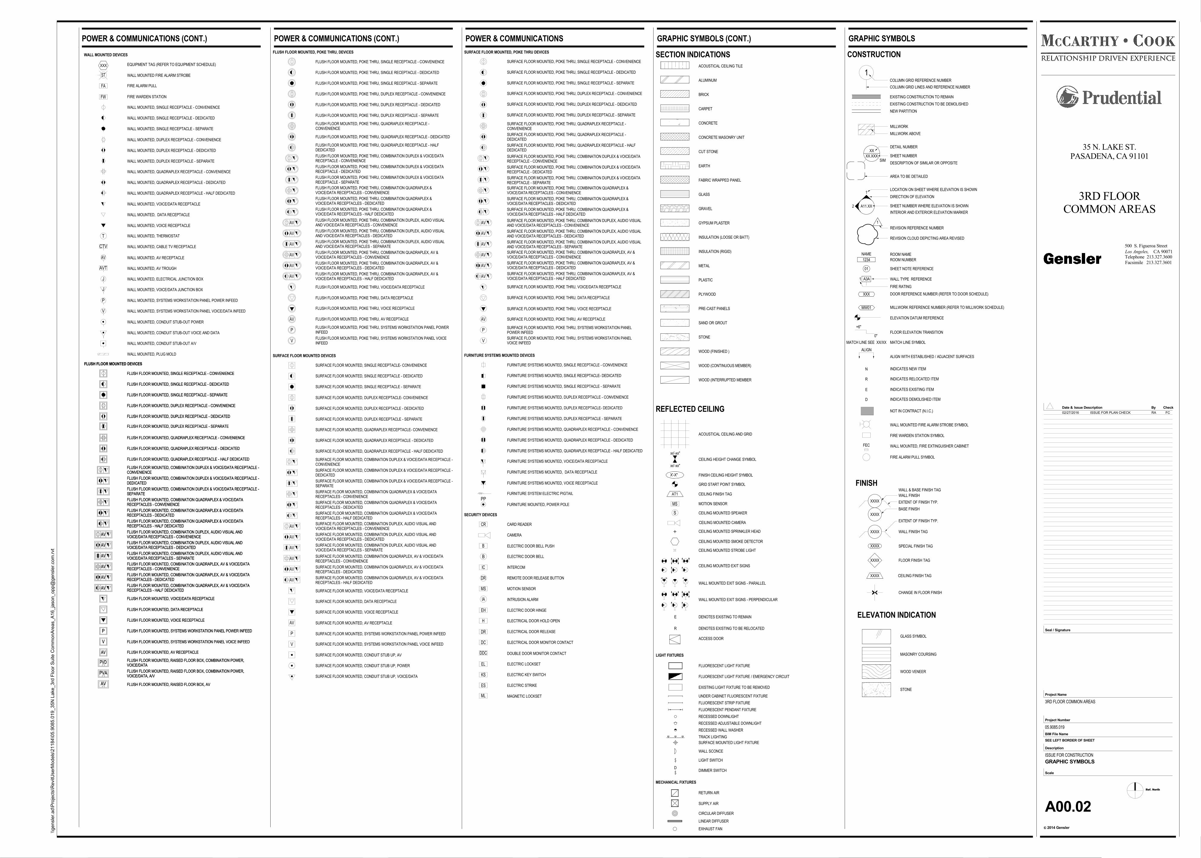
GRAPHIC SYMBOLS
GRAPHIC SYMBOLS (CONT.) GRAPHIC SYMBOLS
ELEVATION INDICATION
GLASS SYMBOL
MASONRY COURSING
WOOD VENEER
STONE
SECTION INDICATIONS
ACOUSTICAL CEILING TILE
ALUMINUM
BRICK
CARPET
CONCRETE
CONCRETE MASONRY UNIT
CUT STONE
EARTH
FABRIC WRAPPED PANEL
GLASS
GRAVEL
GYPSUM PLASTER
INSULATION (LOOSE OR BATT)
INSULATION (RIGID)
METAL
PLYWOOD
PRE-CAST PANELS
SAND OR GROUT
STONE
WOOD (FINISHED )
WOOD (CONTINUOUS MEMBER)
WOOD (INTERRUPTED MEMBER
PLASTIC
FINISH
WALL FINISH
XXXX WALL FINISH TAG
EXTENT OF FINISH TYP.
XXXX SPECIAL FINISH TAG
XXXX FLOOR FINISH TAG
CHANGE IN FLOOR FINISH
XXXX CEILING FINISH TAG
XXXX
XXXX
BASE FINISH
WALL & BASE FINISH TAG
EXTENT OF FINISH TYP.MS
S
FINISH CEILING HEIGHT SYMBOL
GRID START POINT SYMBOL
MOTION SENSOR
CEILING MOUNTED SPEAKER
CEILING MOUNTED CAMERA
CEILING MOUNTED SPRINKLER HEAD
CEILING MOUNTED SMOKE DETECTOR
E DENOTES EXISTING TO REMAIN
R DENOTES EXISTING TO BE RELOCATED
ACCESS DOOR
REFLECTED CEILING
CEILING MOUNTED STROBE LIGHT
ACOUSTICAL CEILING AND GRID
CEILING HEIGHT CHANGE SYMBOL
xx'-xx"
xx'-xx"
X'-X"
AT1 CEILING FINISH TAG
CEILING MOUNTED EXIT SIGNS
WALL MOUNTED EXIT SIGNS - PARALLEL
WALL MOUNTED EXIT SIGNS - PERPENDICULAR
LIGHT FIXTURES
FLUORESCENT LIGHT FIXTURE
FLUORESCENT LIGHT FIXTURE / EMERGENCY CIRCUIT
EXISTING LIGHT FIXTURE TO BE REMOVED
UNDER CABINET FLUORESCENT FIXTURE
FLUORESCENT STRIP FIXTURE
FLUORESCENT PENDANT FIXTURE
RECESSED DOWNLIGHT
RECESSED ADJUSTABLE DOWNLIGHT
RECESSED WALL WASHER
TRACK LIGHTING
SURFACE MOUNTED LIGHT FIXTURE
WALL SCONCE
LIGHT SWITCH
DDIMMER SWITCH
MECHANICAL FIXTURES
RETURN AIR
SUPPLY AIR
CIRCULAR DIFFUSER
LINEAR DIFFUSER
EXHAUST FAN
FEC
XX
XX.XXXSIM
A11.XX
1
1
1
NEW PARTITION
EXISTING CONSTRUCTION TO REMAIN
EXISTING CONSTRUCTION TO BE DEMOLISHED
MILLWORK ABOVE
MILLWORK
COLUMN GRID LINES AND REFERENCE NUMBER
COLUMN GRID REFERENCE NUMBER
DETAIL NUMBER
SHEET NUMBER
DESCRIPTION OF SIMILAR OR OPPOSITE
AREA TO BE DETAILED
LOCATION ON SHEET WHERE ELEVATION IS SHOWN
DIRECTION OF ELEVATION
INTERIOR AND EXTERIOR ELEVATION MARKER
ROOM NAME
ROOM NUMBER
SHEET NOTE REFERENCE
WALL TYPE REFERENCE
DOOR REFERENCE NUMBER (REFER TO DOOR SCHEDULE)
MW01 MILLWORK REFERENCE NUMBER (REFER TO MILLWORK SCHEDULE)
ELEVATION DATUM REFERENCE
MATCH LINE SYMBOL
ALIGN WITH ESTABLISHED / ADJACENT SURFACES
FIRE WARDEN STATION SYMBOL
WALL MOUNTED FIRE ALARM STROBE SYMBOL
FIRE ALARM PULL SYMBOL
WALL MOUNTED, FIRE EXTINGUISHER CABINET
REVISION REFERENCE NUMBER
REVISION CLOUD DEPICTING AREA REVISED
CONSTRUCTION
+6"
0"
XXX
NAME
1234
01
A3A1
ALIGN
MATCH LINE SEE XX/XX
2 SHEET NUMBER WHERE ELEVATION IS SHOWN
FIRE RATING
FLOOR ELEVATION TRANSITION
INDICATES NEW ITEMN
INDICATES RELOCATED ITEMR
INDICATES EXISTING ITEME
INDICATES DEMOLISHED ITEMD
NOT IN CONTRACT (N.I.C.)
FW
ST
FA
V
P
J
J
AVT
AV
CTV
T
WALL MOUNTED DEVICES
XXX EQUIPMENT TAG (REFER TO EQUIPMENT SCHEDULE)
WALL MOUNTED FIRE ALARM STROBE
FIRE ALARM PULL
FIRE WARDEN STATION
WALL MOUNTED, SINGLE RECEPTACLE - CONVENIENCE
WALL MOUNTED, DUPLEX RECEPTACLE - CONVENIENCE
WALL MOUNTED, QUADRAPLEX RECEPTACLE - CONVENIENCE
WALL MOUNTED, VOICE/DATA RECEPTACLE
WALL MOUNTED, DATA RECEPTACLE
WALL MOUNTED, VOICE RECEPTACLE
WALL MOUNTED, THERMOSTAT
WALL MOUNTED, CABLE TV RECEPTACLE
WALL MOUNTED, AV RECEPTACLE
WALL MOUNTED, AV TROUGH
WALL MOUNTED, ELECTRICAL JUNCTION BOX
WALL MOUNTED, VOICE/DATA JUNCTION BOX
WALL MOUNTED, SYSTEMS WORKSTATION PANEL POWER INFEED
WALL MOUNTED, SYSTEMS WORKSTATION PANEL VOICE/DATA INFEED
WALL MOUNTED, CONDUIT STUB-OUT POWER
WALL MOUNTED, CONDUIT STUB-OUT VOICE AND DATA
WALL MOUNTED, CONDUIT STUB-OUT A/V
WALL MOUNTED, PLUG MOLD
WALL MOUNTED, SINGLE RECEPTACLE - DEDICATED
WALL MOUNTED, DUPLEX RECEPTACLE - DEDICATED
WALL MOUNTED, QUADRAPLEX RECEPTACLE - DEDICATED
WALL MOUNTED, SINGLE RECEPTACLE - SEPARATE
WALL MOUNTED, DUPLEX RECEPTACLE - SEPARATE
WALL MOUNTED, QUADRAPLEX RECEPTACLE - HALF DEDICATED
AV
PVA
PVD
AV
V
P
AV
AV
AV
AV
AV
AV
FLUSH FLOOR MOUNTED DEVICES
FLUSH FLOOR MOUNTED, SINGLE RECEPTACLE - CONVENIENCE
FLUSH FLOOR MOUNTED, DUPLEX RECEPTACLE - CONVENIENCE
FLUSH FLOOR MOUNTED, QUADRAPLEX RECEPTACLE - CONVENIENCE
FLUSH FLOOR MOUNTED, COMBINATION DUPLEX & VOICE/DATA RECEPTACLE -CONVENIENCE
FLUSH FLOOR MOUNTED, COMBINATION QUADRAPLEX & VOICE/DATARECEPTACLES - CONVENIENCE
FLUSH FLOOR MOUNTED, COMBINATION DUPLEX, AUDIO VISUAL ANDVOICE/DATA RECEPTACLES - CONVENIENCE
FLUSH FLOOR MOUNTED, COMBINATION QUADRAPLEX, AV & VOICE/DATARECEPTACLES - CONVENIENCE
FLUSH FLOOR MOUNTED, VOICE/DATA RECEPTACLE
FLUSH FLOOR MOUNTED, DATA RECEPTACLE
FLUSH FLOOR MOUNTED, VOICE RECEPTACLE
FLUSH FLOOR MOUNTED, SYSTEMS WORKSTATION PANEL POWER INFEED
FLUSH FLOOR MOUNTED, SYSTEMS WORKSTATION PANEL VOICE INFEED
FLUSH FLOOR MOUNTED, AV RECEPTACLE
FLUSH FLOOR MOUNTED, RAISED FLOOR BOX, COMBINATION POWER,VOICE/DATA
FLUSH FLOOR MOUNTED, RAISED FLOOR BOX, COMBINATION POWER,VOICE/DATA, A/V
FLUSH FLOOR MOUNTED, RAISED FLOOR BOX, AV
FLUSH FLOOR MOUNTED, SINGLE RECEPTACLE - DEDICATED
FLUSH FLOOR MOUNTED, SINGLE RECEPTACLE - SEPARATE
FLUSH FLOOR MOUNTED, DUPLEX RECEPTACLE - DEDICATED
FLUSH FLOOR MOUNTED, DUPLEX RECEPTACLE - SEPARATE
FLUSH FLOOR MOUNTED, QUADRAPLEX RECEPTACLE - DEDICATED
FLUSH FLOOR MOUNTED, QUADRAPLEX RECEPTACLE - HALF DEDICATED
FLUSH FLOOR MOUNTED, COMBINATION DUPLEX & VOICE/DATA RECEPTACLE -DEDICATED
FLUSH FLOOR MOUNTED, COMBINATION DUPLEX & VOICE/DATA RECEPTACLE -SEPARATE
FLUSH FLOOR MOUNTED, COMBINATION QUADRAPLEX & VOICE/DATARECEPTACLES - DEDICATED
FLUSH FLOOR MOUNTED, COMBINATION QUADRAPLEX & VOICE/DATARECEPTACLES - HALF DEDICATED
FLUSH FLOOR MOUNTED, COMBINATION DUPLEX, AUDIO VISUAL ANDVOICE/DATA RECEPTACLES - DEDICATED
FLUSH FLOOR MOUNTED, COMBINATION DUPLEX, AUDIO VISUAL ANDVOICE/DATA RECEPTACLES - SEPARATE
FLUSH FLOOR MOUNTED, COMBINATION QUADRAPLEX, AV & VOICE/DATARECEPTACLES - DEDICATED
FLUSH FLOOR MOUNTED, COMBINATION QUADRAPLEX, AV & VOICE/DATARECEPTACLES - HALF DEDICATED
AV
PVA
PVD
AV
V
P
AV
AV
AV
AV
AV
AV
FLUSH FLOOR MOUNTED DEVICES
FLUSH FLOOR MOUNTED, SINGLE RECEPTACLE - CONVENIENCE
FLUSH FLOOR MOUNTED, DUPLEX RECEPTACLE - CONVENIENCE
FLUSH FLOOR MOUNTED, QUADRAPLEX RECEPTACLE - CONVENIENCE
FLUSH FLOOR MOUNTED, COMBINATION DUPLEX & VOICE/DATA RECEPTACLE -CONVENIENCE
FLUSH FLOOR MOUNTED, COMBINATION QUADRAPLEX & VOICE/DATARECEPTACLES - CONVENIENCE
FLUSH FLOOR MOUNTED, COMBINATION DUPLEX, AUDIO VISUAL ANDVOICE/DATA RECEPTACLES - CONVENIENCE
FLUSH FLOOR MOUNTED, COMBINATION QUADRAPLEX, AV & VOICE/DATARECEPTACLES - CONVENIENCE
FLUSH FLOOR MOUNTED, VOICE/DATA RECEPTACLE
FLUSH FLOOR MOUNTED, DATA RECEPTACLE
FLUSH FLOOR MOUNTED, VOICE RECEPTACLE
FLUSH FLOOR MOUNTED, SYSTEMS WORKSTATION PANEL POWER INFEED
FLUSH FLOOR MOUNTED, SYSTEMS WORKSTATION PANEL VOICE INFEED
FLUSH FLOOR MOUNTED, AV RECEPTACLE
FLUSH FLOOR MOUNTED, RAISED FLOOR BOX, COMBINATION POWER,VOICE/DATA
FLUSH FLOOR MOUNTED, RAISED FLOOR BOX, COMBINATION POWER,VOICE/DATA, A/V
FLUSH FLOOR MOUNTED, RAISED FLOOR BOX, AV
FLUSH FLOOR MOUNTED, SINGLE RECEPTACLE - DEDICATED
FLUSH FLOOR MOUNTED, SINGLE RECEPTACLE - SEPARATE
FLUSH FLOOR MOUNTED, DUPLEX RECEPTACLE - DEDICATED
FLUSH FLOOR MOUNTED, DUPLEX RECEPTACLE - SEPARATE
FLUSH FLOOR MOUNTED, QUADRAPLEX RECEPTACLE - DEDICATED
FLUSH FLOOR MOUNTED, QUADRAPLEX RECEPTACLE - HALF DEDICATED
FLUSH FLOOR MOUNTED, COMBINATION DUPLEX & VOICE/DATA RECEPTACLE -DEDICATED
FLUSH FLOOR MOUNTED, COMBINATION DUPLEX & VOICE/DATA RECEPTACLE -SEPARATE
FLUSH FLOOR MOUNTED, COMBINATION QUADRAPLEX & VOICE/DATARECEPTACLES - DEDICATED
FLUSH FLOOR MOUNTED, COMBINATION QUADRAPLEX & VOICE/DATARECEPTACLES - HALF DEDICATED
FLUSH FLOOR MOUNTED, COMBINATION DUPLEX, AUDIO VISUAL ANDVOICE/DATA RECEPTACLES - DEDICATED
FLUSH FLOOR MOUNTED, COMBINATION DUPLEX, AUDIO VISUAL ANDVOICE/DATA RECEPTACLES - SEPARATE
FLUSH FLOOR MOUNTED, COMBINATION QUADRAPLEX, AV & VOICE/DATARECEPTACLES - DEDICATED
FLUSH FLOOR MOUNTED, COMBINATION QUADRAPLEX, AV & VOICE/DATARECEPTACLES - HALF DEDICATED
V
P
AV
AV
AV
AV
AV
AV
AV
FLUSH FLOOR MOUNTED, POKE THRU, DEVICES
FLUSH FLOOR MOUNTED, POKE THRU, SINGLE RECEPTACLE - CONVENIENCE
FLUSH FLOOR MOUNTED, POKE THRU, DUPLEX RECEPTACLE - CONVENIENCE
FLUSH FLOOR MOUNTED, POKE THRU, QUADRAPLEX RECEPTACLE -CONVENIENCE
FLUSH FLOOR MOUNTED, POKE THRU, COMBINATION DUPLEX & VOICE/DATARECEPTACLE - CONVENIENCE
FLUSH FLOOR MOUNTED, POKE THRU, COMBINATION QUADRAPLEX &VOICE/DATA RECEPTACLES - CONVENIENCE
FLUSH FLOOR MOUNTED, POKE THRU, COMBINATION DUPLEX, AUDIO VISUALAND VOICE/DATA RECEPTACLES - CONVENIENCE
FLUSH FLOOR MOUNTED, POKE THRU, COMBINATION QUADRAPLEX, AV &VOICE/DATA RECEPTACLES - CONVENIENCE
FLUSH FLOOR MOUNTED, POKE THRU, VOICE/DATA RECEPTACLE
FLUSH FLOOR MOUNTED, POKE THRU, DATA RECEPTACLE
FLUSH FLOOR MOUNTED, POKE THRU, VOICE RECEPTACLE
FLUSH FLOOR MOUNTED, POKE THRU, AV RECEPTACLE
FLUSH FLOOR MOUNTED, POKE THRU, SYSTEMS WORKSTATION PANEL POWERINFEED
FLUSH FLOOR MOUNTED, POKE THRU, SYSTEMS WORKSTATION PANEL VOICEINFEED
FLUSH FLOOR MOUNTED, POKE THRU, SINGLE RECEPTACLE - DEDICATED
FLUSH FLOOR MOUNTED, POKE THRU, SINGLE RECEPTACLE - SEPARATE
FLUSH FLOOR MOUNTED, POKE THRU, DUPLEX RECEPTACLE - DEDICATED
FLUSH FLOOR MOUNTED, POKE THRU, DUPLEX RECEPTACLE - SEPARATE
FLUSH FLOOR MOUNTED, POKE THRU, QUADRAPLEX RECEPTACLE - DEDICATED
FLUSH FLOOR MOUNTED, POKE THRU, QUADRAPLEX RECEPTACLE - HALFDEDICATED
FLUSH FLOOR MOUNTED, POKE THRU, COMBINATION DUPLEX & VOICE/DATARECEPTACLE - DEDICATED
FLUSH FLOOR MOUNTED, POKE THRU, COMBINATION DUPLEX & VOICE/DATARECEPTACLE - SEPARATE
FLUSH FLOOR MOUNTED, POKE THRU, COMBINATION QUADRAPLEX &VOICE/DATA RECEPTACLES - DEDICATED
FLUSH FLOOR MOUNTED, POKE THRU, COMBINATION QUADRAPLEX &VOICE/DATA RECEPTACLES - HALF DEDICATED
FLUSH FLOOR MOUNTED, POKE THRU, COMBINATION DUPLEX, AUDIO VISUALAND VOICE/DATA RECEPTACLES - DEDICATED
FLUSH FLOOR MOUNTED, POKE THRU, COMBINATION DUPLEX, AUDIO VISUALAND VOICE/DATA RECEPTACLES - SEPARATE
FLUSH FLOOR MOUNTED, POKE THRU, COMBINATION QUADRAPLEX, AV &VOICE/DATA RECEPTACLES - DEDICATED
FLUSH FLOOR MOUNTED, POKE THRU, COMBINATION QUADRAPLEX, AV &VOICE/DATA RECEPTACLES - HALF DEDICATED
V
P
AV
AV
AV
AV
AV
AV
AV
SURFACE FLOOR MOUNTED, POKE THRU DEVICES
SURFACE FLOOR MOUNTED, POKE THRU, SINGLE RECEPTACLE - CONVENIENCE
SURFACE FLOOR MOUNTED, POKE THRU, DUPLEX RECEPTACLE - CONVENIENCE
SURFACE FLOOR MOUNTED, POKE THRU, QUADRAPLEX RECEPTACLE -CONVENIENCE
SURFACE FLOOR MOUNTED, POKE THRU, COMBINATION DUPLEX & VOICE/DATARECEPTACLE - CONVENIENCE
SURFACE FLOOR MOUNTED, POKE THRU, COMBINATION QUADRAPLEX &VOICE/DATA RECEPTACLES - CONVENIENCE
SURFACE FLOOR MOUNTED, POKE THRU, COMBINATION DUPLEX, AUDIO VISUALAND VOICE/DATA RECEPTACLES - CONVENIENCE
SURFACE FLOOR MOUNTED, POKE THRU, COMBINATION QUADRAPLEX, AV &VOICE/DATA RECEPTACLES - CONVENIENCE
SURFACE FLOOR MOUNTED, POKE THRU, VOICE/DATA RECEPTACLE
SURFACE FLOOR MOUNTED, POKE THRU, DATA RECEPTACLE
SURFACE FLOOR MOUNTED, POKE THRU, VOICE RECEPTACLE
SURFACE FLOOR MOUNTED, POKE THRU, AV RECEPTACLE
SURFACE FLOOR MOUNTED, POKE THRU, SYSTEMS WORKSTATION PANELPOWER INFEED
SURFACE FLOOR MOUNTED, POKE THRU, SYSTEMS WORKSTATION PANELVOICE INFEED
SURFACE FLOOR MOUNTED, POKE THRU, SINGLE RECEPTACLE - DEDICATED
SURFACE FLOOR MOUNTED, POKE THRU, DUPLEX RECEPTACLE - DEDICATED
SURFACE FLOOR MOUNTED, POKE THRU, QUADRAPLEX RECEPTACLE -DEDICATED
SURFACE FLOOR MOUNTED, POKE THRU, COMBINATION DUPLEX & VOICE/DATARECEPTACLE - DEDICATED
SURFACE FLOOR MOUNTED, POKE THRU, COMBINATION QUADRAPLEX &VOICE/DATA RECEPTACLES - DEDICATED
SURFACE FLOOR MOUNTED, POKE THRU, COMBINATION DUPLEX, AUDIO VISUALAND VOICE/DATA RECEPTACLES - DEDICATED
SURFACE FLOOR MOUNTED, POKE THRU, COMBINATION QUADRAPLEX, AV &VOICE/DATA RECEPTACLES - DEDICATED
SURFACE FLOOR MOUNTED, POKE THRU, SINGLE RECEPTACLE - SEPARATE
SURFACE FLOOR MOUNTED, POKE THRU, DUPLEX RECEPTACLE - SEPARATE
SURFACE FLOOR MOUNTED, POKE THRU, QUADRAPLEX RECEPTACLE - HALFDEDICATED
SURFACE FLOOR MOUNTED, POKE THRU, COMBINATION DUPLEX & VOICE/DATARECEPTACLE - SEPARATE
SURFACE FLOOR MOUNTED, POKE THRU, COMBINATION QUADRAPLEX &VOICE/DATA RECEPTACLES - HALF DEDICATED
SURFACE FLOOR MOUNTED, POKE THRU, COMBINATION DUPLEX, AUDIO VISUALAND VOICE/DATA RECEPTACLES - SEPARATE
SURFACE FLOOR MOUNTED, POKE THRU, COMBINATION QUADRAPLEX, AV &VOICE/DATA RECEPTACLES - HALF DEDICATED
AV
AV
V
P
AV
AV
AV
AV
AV
SURFACE FLOOR MOUNTED DEVICES
SURFACE FLOOR MOUNTED, SINGLE RECEPTACLE- CONVENIENCE
SURFACE FLOOR MOUNTED, DUPLEX RECEPTACLE- CONVENIENCE
SURFACE FLOOR MOUNTED, QUADRAPLEX RECEPTACLE- CONVENIENCE
SURFACE FLOOR MOUNTED, COMBINATION DUPLEX & VOICE/DATA RECEPTACLE -CONVENIENCE
SURFACE FLOOR MOUNTED, COMBINATION QUADRAPLEX & VOICE/DATARECEPTACLES - CONVENIENCE
SURFACE FLOOR MOUNTED, COMBINATION DUPLEX, AUDIO VISUAL ANDVOICE/DATA RECEPTACLES - CONVENIENCE
SURFACE FLOOR MOUNTED, COMBINATION QUADRAPLEX, AV & VOICE/DATARECEPTACLES - CONVENIENCE
SURFACE FLOOR MOUNTED, VOICE/DATA RECEPTACLE
SURFACE FLOOR MOUNTED, DATA RECEPTACLE
SURFACE FLOOR MOUNTED, VOICE RECEPTACLE
SURFACE FLOOR MOUNTED, AV RECEPTACLE
SURFACE FLOOR MOUNTED, SYSTEMS WORKSTATION PANEL POWER INFEED
SURFACE FLOOR MOUNTED, SYSTEMS WORKSTATION PANEL VOICE INFEED
SURFACE FLOOR MOUNTED, CONDUIT STUB UP, AV
SURFACE FLOOR MOUNTED, CONDUIT STUB UP, POWER
SURFACE FLOOR MOUNTED, CONDUIT STUB UP, VOICE/DATA
SURFACE FLOOR MOUNTED, SINGLE RECEPTACLE - DEDICATED
SURFACE FLOOR MOUNTED, DUPLEX RECEPTACLE - DEDICATED
SURFACE FLOOR MOUNTED, QUADRAPLEX RECEPTACLE - DEDICATED
SURFACE FLOOR MOUNTED, COMBINATION DUPLEX & VOICE/DATA RECEPTACLE -DEDICATED
SURFACE FLOOR MOUNTED, SINGLE RECEPTACLE - SEPARATE
SURFACE FLOOR MOUNTED, DUPLEX RECEPTACLE - SEPARATE
SURFACE FLOOR MOUNTED, QUADRAPLEX RECEPTACLE - HALF DEDICATED
SURFACE FLOOR MOUNTED, COMBINATION DUPLEX & VOICE/DATA RECEPTACLE -SEPARATE
SURFACE FLOOR MOUNTED, COMBINATION QUADRAPLEX & VOICE/DATARECEPTACLES - DEDICATED
SURFACE FLOOR MOUNTED, COMBINATION DUPLEX, AUDIO VISUAL ANDVOICE/DATA RECEPTACLES - DEDICATED
SURFACE FLOOR MOUNTED, COMBINATION QUADRAPLEX, AV & VOICE/DATARECEPTACLES - DEDICATED
SURFACE FLOOR MOUNTED, COMBINATION QUADRAPLEX & VOICE/DATARECEPTACLES - HALF DEDICATED
SURFACE FLOOR MOUNTED, COMBINATION DUPLEX, AUDIO VISUAL ANDVOICE/DATA RECEPTACLES - SEPARATE
SURFACE FLOOR MOUNTED, COMBINATION QUADRAPLEX, AV & VOICE/DATARECEPTACLES - HALF DEDICATED
PP
FURNITURE SYSTEMS MOUNTED DEVICES
FURNITURE SYSTEMS MOUNTED, SINGLE RECEPTACLE - CONVENIENCE
FURNITURE SYSTEMS MOUNTED, DUPLEX RECEPTACLE - CONVENIENCE
FURNITURE SYSTEMS MOUNTED, QUADRAPLEX RECEPTACLE - CONVENIENCE
FURNITURE SYSTEMS MOUNTED, VOICE/DATA RECEPTACLE
FURNITURE SYSTEMS MOUNTED, DATA RECEPTACLE
FURNITURE SYSTEMS MOUNTED, VOICE RECEPTACLE
FURNITURE SYSTEM ELECTRIC PIGTAIL
FURNITURE MOUNTED, POWER POLE
FURNITURE SYSTEMS MOUNTED, SINGLE RECEPTACLE- DEDICATED
FURNITURE SYSTEMS MOUNTED, SINGLE RECEPTACLE - SEPARATE
FURNITURE SYSTEMS MOUNTED, DUPLEX RECEPTACLE- DEDICATED
FURNITURE SYSTEMS MOUNTED, DUPLEX RECEPTACLE - SEPARATE
FURNITURE SYSTEMS MOUNTED, QUADRAPLEX RECEPTACLE - DEDICATED
FURNITURE SYSTEMS MOUNTED, QUADRAPLEX RECEPTACLE - HALF DEDICATED
ML
ES
KS
EL
DC
DDC
DR
H
EH
IA
MS
DR
IC
B
B
CR
SECURITY DEVICES
CARD READER
ELECTRIC DOOR BELL PUSH
ELECTRIC DOOR BELL
INTERCOM
REMOTE DOOR RELEASE BUTTON
MOTION SENSOR
INTRUSION ALARM
ELECTRIC DOOR HINGE
ELECTRICAL DOOR HOLD OPEN
ELECTRICAL DOOR RELEASE
ELECTRICAL DOOR MONITOR CONTACT
DOUBLE DOOR MONITOR CONTACT
ELECTRIC LOCKSET
ELECTRIC KEY SWITCH
ELECTRIC STRIKE
MAGNETIC LOCKSET
CAMERA
POWER & COMMUNICATIONS (CONT.) POWER & COMMUNICATIONS (CONT.) POWER & COMMUNICATIONS
02/27/2016 ISSUE FOR PLAN CHECK RA FC
Ref. North
CA 90071Los Angeles,
2014 Gensler
Project Number
BIM File Name
Scale
Description
c
Project Name
Seal / Signature
Check
Facsimile 213.327.3601
Telephone 213.327.3600
Date & By
500 S. Figueroa Street
Issue Description
SEE LEFT BORDER OF SHEET
\\ge
nsl
er.
ad\P
roje
cts
\RevitU
serM
od
els
\21
184
\05
.90
85.0
19
_35
N L
ake
_3rd
Flo
or
Su
ite C
om
mo
nA
reas_A
16_ja
son_o
pp@
gen
sle
r.com
.rvt
35 N. LAKE ST.PASADENA, CA 91101
3RD FLOORCOMMON AREAS
3RD FLOOR COMMON AREAS
05.9085.019
ISSUE FOR CONSTRUCTION
A00.03
PASADENA GENERAL NOTES
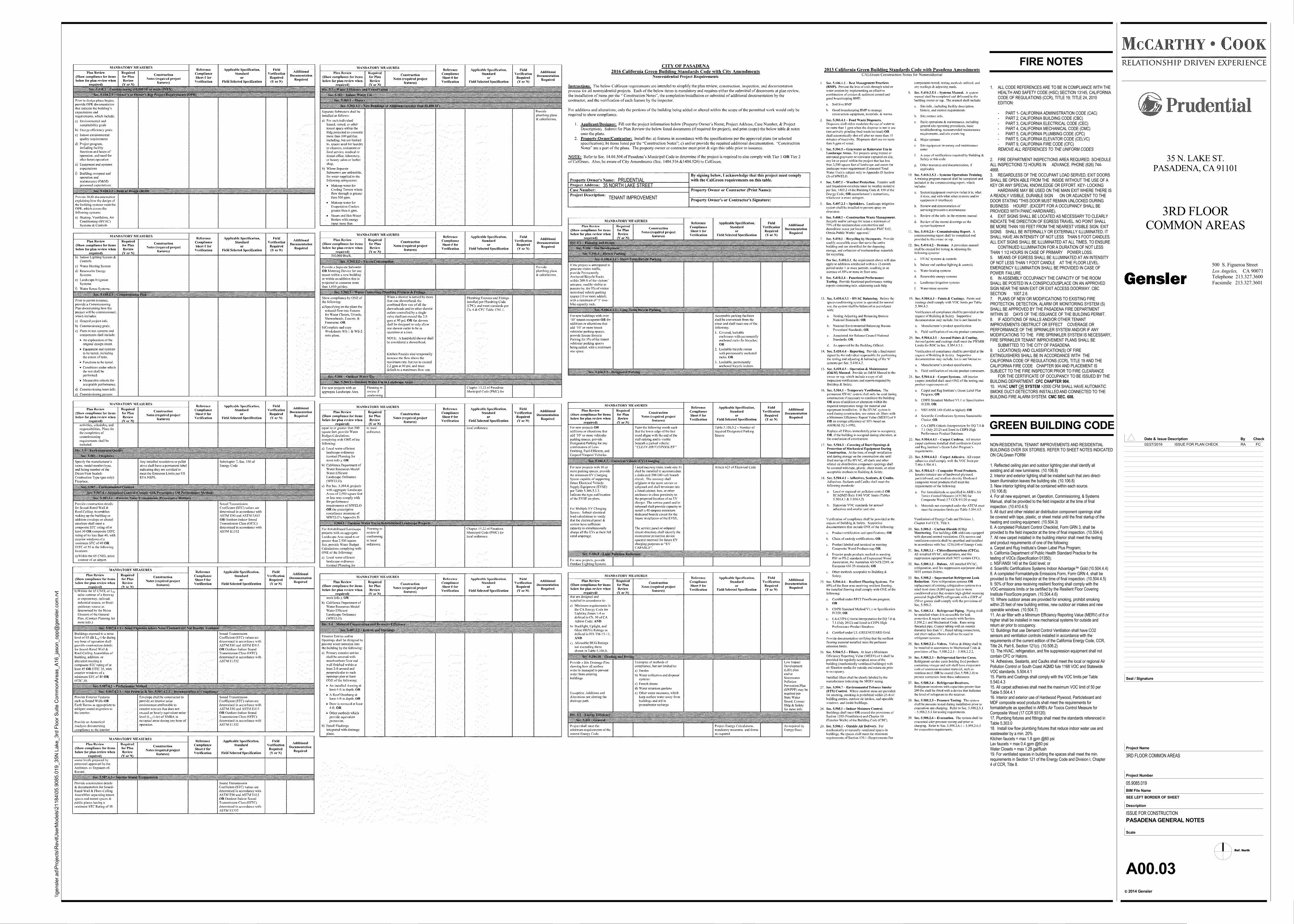
1. ALL CODE REFERENCES ARE TO BE IN COMPLIANCE WITH THEHEALTH AND SAFETY CODE (HSC) SECTION 13145, CALIFORNIACODE OF REGULATIONS (CCR), TITLE 19; TITLE 24, 2010EDITION:
- PART 1- CALIFORNIA ADMINISTRATION CODE (CAC)- PART 2, CALIFORNIA BUILDING CODE (CBC)- PART 3, CALIFORNIA ELECTRICAL CODE (CEC)- PART 4, CALIFORNIA MECHANICAL CODE (CMC)- PART 5, CALIFORNIA PLUMBING CODE (CPC)- PART 5, CALIFORNIA ELEVATOR CODE (CELVC)- PART 9, CALIFORNIA FIRE CODE (CFC)REMOVE ALL REFERENCES TO THE UNIFORM CODES
2. FIRE DEPARTMENT INSPECTIONS AREA REQUIRED. SCHEDULEALL INSPECTIONS 72 HOURS IN ADVANCE. PHONE (626) 744-4668.3. REGARDLESS OF THE OCCUPANT LOAD SERVED, EXIT DOORSSHALL BE OPEN ABLE FROM THE INSIDE WITHOUT THE USE OF AKEY OR ANY SPECIAL KNOWLEDGE OR EFFORT. KEY- LOCKING
HARDWARE MAY BE USED ON THE MAIN EXIT WHERE THERE ISA READILY VISIBLE, DURABLE SIGN ON OR ADJACENT TO THEDOOR STATING "THIS DOOR MUST REMAIN UNLOCKED DURINGBUSINESS HOURS". (EXCEPT FOR A OCCUPANCY SHALL BEPROVIDED WITH PANIC HARDWARE).4. EXIT SIGNS SHALL BE LOCATED AS NECESSARY TO CLEARLYINDICATE THE DIRECTION OF EGRESS TRAVEL. NO POINT SHALLBE MORE THAN 100 FEET FROM THE NEAREST VISIBLE SIGN. EXITSIGNS SHALL BE INTERNALLY OR EXTERNALLY ILLUMINATED, ITSHALL HAVE AN INTENSITY OF NOT LESS THAN 5 FOOT CANDLES.ALL EXIT SIGNS SHALL BE ILLUMINATED AT ALL TIMES, TO ENSURE
CONTINUED ILLUMINATION FOR A DURATION OF NOT LESSTHAN 1 1/2 HOURS IN CASE OF PRIMARY POWER LOSS.5. MEANS OF EGRESS SHALL BE ILLUMINATED AT AN INTENSITYOF NOT LESS THAN 1 FOOT CANDLE AT THE FLOOR LEVEL.EMERGENCY ILLUMINATION SHALL BE PROVIDED IN CASE OFPOWER FAILURE.6. IN ASSEMBLY OCCUPANCY THE CAPACITY OF THE ROOMSHALL BE POSTED IN A CONSPICUOUS PLACE ON AN APPROVEDSIGN NEAR THE MAIN EXIT OR EXIT ACCESS DOORWAY. CBCSECTION 1007.2.6.7. PLANS OF NEW OR MODIFICATIONS TO EXISTING FIREPROTECTION, DETECTION, ALARM OR MONITORING SYSTEM (S)SHALL BE APPROVED BY THE PASADENA FIRE DEPARTMENTWITHIN 30 DAYS OF THE ISSUANCE OF THE BUILDING PERMIT.8. IF ADDITIONS OF WALLS AND/OR OTHER TENANTIMPROVEMENTS OBSTRUCT OR EFFECT COVERAGE ORPERFORMANCE OF THE SPRINKLER SYSTEM AND/OR IF ANYMODIFICATIONS TO THE FIRE SPRINKLER SYSTEM IS NECESSARY,FIRE SPRINKLER TENANT IMPROVEMENT PLANS SHALL BE
SUBMITTED TO THE CITY OF PASADENA.9. LOCATION(S) AND CLASSIFICATION(S) OF FIREEXTINGUISHERS SHALL BE IN ACCORDANCE WITH THECALIFORNIA CODE OF REGULATIONS (CCR), TITLE 19 AND THECALIFORNIA FIRE CODE CHAPTER 904 AND PLACEMENT ISSUBJECT TO THE FIRE INSPECTOR PRIOR TO FIRE CLEARANCE
FOR THE CERTIFICATE OF OCCUPANCY TO BE ISSUED BY THEBUILDING DEPARTMENT. CFC CHAPTER 904.10. HVAC UNIT OR SYSTEM >2000 CFM SHALL HAVE AUTOMATICSMOKE DUCT-DETECTORS INSTALLED AND CONNECTED TO THEBUILDING FIRE ALARM SYSTEM. CMC SEC. 608.
FIRE NOTES
NON-RESIDENTIAL TENANT IMPROVEMENTS AND RESIDENTIALBUILDINGS OVER SIX STORIES. REFER TO SHEET NOTES INDICATEDON CALGreen FORM
1. Reflected ceiling plan and outdoor lighting plan shall identify allexisting and all new luminaires. (10.106.8)2. Interior and exterior lighting shall be installed such that zero direct-beam illumination leaves the building site. (10.106.8)3. New interior lighting shall be contained within each source.(10.106.8)4. For all new equipment, an Operation, Commissioning, & SystemsManual, shall be provided to the field inspector at the time of finalinspection. (10.410.4.5)5. All duct and other related air distribution component openings shallbe covered with tape, plastic, or sheet metal until the final startup of theheating and cooling equipment. (10.504.3)6. A completed Pollutant Control Checklist, Form GRN 3, shall beprovided to the field inspector at the time of final inspection. (10.504.4)7. All new carpet installed in the building interior shall meet the testingand product requirements of one of the following:a. Carpet and Rug Institute’s Green Label Plus Program;b. California Department of Public Health Standard Practice for thetesting of VOCs (Specification 01350);c. NSF/ANSI 140 at the Gold level; ord. Scientific Certifications Systems Indoor Advantage™ Gold (10.504.4.4)8. A completed Formaldehyde Emissions Form, Form GRN 4, shall beprovided to the field inspector at the time of final inspection. (10.504.4.5)9. 50% of floor area receiving resilient flooring shall comply with theVOC-emissions limits or be certified by the Resilient Floor CoveringInstitute FloorScore program. (10.504.4.6)10. Where outdoor areas are provided for smoking, prohibit smokingwithin 25 feet of new building entries, new outdoor air intakes and newoperable windows. (10.504.7)11. An air filter with a Minimum Efficiency Reporting Value (MERV) of 8 orhigher shall be installed in new mechanical systems for outside andreturn air prior to occupancy.12. Buildings that use Demand Control Ventilation shall have CO2sensors and ventilation controls installed in accordance with therequirements of the current edition of the California Energy Code, CCR,Title 24, Part 6, Section 121(c). (10.506.2)13. The HVAC, refrigeration, and fire suppression equipment shall notcontain CFC or Halons.14. Adhesives, Sealants, and Caulks shall meet the local or regional AirPollution Control or South Coast AQMD fule 1168 VOC and StatewideVOC standards. 5.504.4.115. Paints and Coatings shall comply with the VOC limits per Table5.540.4.315. All carpet adhesives shall meet the maximum VOC limit of 50 perTable 5.504.4.116. Interior and exterior use of Hardwood Plywood, Particleboard andMDF composite wood products shall meet the requirements forformaldehyde as specified in ARB's Air Toxics Control Measure forComposite Wood (17 CCR 93120)17. Plumbing fixtures and fittings shall meet the standards referenced inTable 5.303.018. Install low flow plumbing fixtures that reduce indoor water use andwastewater by a min. 20%Kitchen faucets = max 1.8 gpm @60 psiLav faucets = max 0.4 gpm @60 psiWater Closets = max 1.28 gal/flush19. For ventilated spaces in building the spaces shall meet the min.requirements in Section 121 of the Energy Code and Division I, Chapter4 of CCR, Title 8.
GREEN BUILDING CODE
35 NORTH LAKE STREETPRUDENTIAL
TENANT IMPROVEMENT
02/27/2016 ISSUE FOR PLAN CHECK RA FC
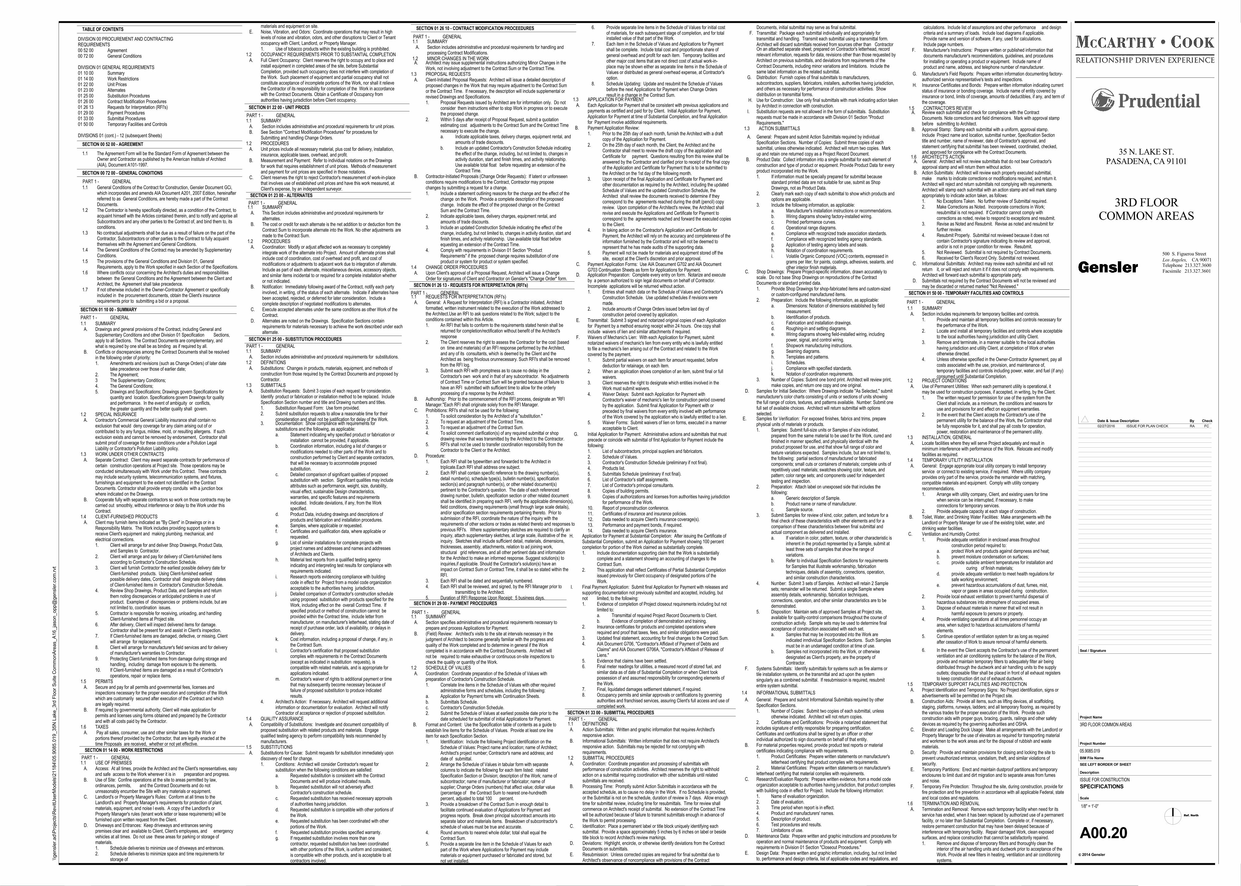
TABLE OF CONTENTS
DIVISION 00 PROCUREMENT AND CONTRACTINGREQUIREMENTS00 52 00 Agreement00 72 00 General Conditions
DIVISION 01 GENERAL REQUIREMENTS01 10 00 Summary01 14 00 Work Restrictions01 22 00 Unit Prices01 23 00 Alternates01 25 00 Substitution Procedures01 26 00 Contract Modification Procedures01 26 13 Requests for Interpretation (RFI's)01 29 00 Payment Procedures01 33 00 Submittal Procedures01 50 00 Temporary Facilities and Controls
DIVISIONS 01 (cont.) - 12 (subsequent Sheets)
SECTION 00 52 00 - AGREEMENT
1.1 The Agreement Form will be the Standard Form of Agreement between theOwner and Contractor as published by the American Institute of Architect(AIA), Document A101-1997.
SECTION 00 72 00 - GENERAL CONDITIONS
1.1 General Conditions of the Contract for Construction, Gensler Document GCi,which incorporates and amends AIA Document A201, 2007 Edition, hereinafterreferred to as General Conditions, are hereby made a part of the ContractDocuments.
1.2 The Contractor is hereby specifically directed, as a condition of the Contract, toacquaint himself with the Articles contained therein, and to notify and apprise allSubcontractors and any other parties to the Contract of, and bind them to, itsconditions.
1.3 No contractual adjustments shall be due as a result of failure on the part of theContractor, Subcontractors or other parties to the Contract to fully acquaintthemselves with the Agreement and General Conditions.
1.4 The General Conditions of the Contract may be amended by SupplementaryConditions.
1.5 The provisions of the General Conditions and Division 01, GeneralRequirements, apply to the Work specified in each Section of the Specifications.
1.6 Where conflicts occur concerning the Architect's duties and responsibilitiesbetween the General Conditions and the Agreement between the Client andArchitect, the Agreement shall take precedence.
1.7 If not otherwise included in the Owner-Contractor Agreement or specificallyincluded in the procurement documents, obtain the Client's insurancerequirements prior to submitting a bid or a proposal.
SECTION 01 10 00 - SUMMARY
1.1 SUMMARY A. Drawings and general provisions of the Contract, including General and
Supplementary Conditions and other Division 01 Specification Sections,apply to all Sections. The Contract Documents are complementary, andwhat is required by one shall be as binding as if required by all.
B. Conflicts or discrepancies among the Contract Documents shall be resolvedin the following order of priority:1. Amendments and revisions (such as Change Orders) of later date
take precedence over those of earlier date;2. The Agreement;3 The Supplementary Conditions;4. The General Conditions;5. Drawings and Specifications; Drawings govern Specifications for
quantity and location. Specifications govern Drawings for qualityand performance. In the event of ambiguity or conflicts, the greater quantity and the better quality shall govern.
1.2 SPECIAL INSURANCE A. Contractor's Commercial General Liability insurance shall contain no
exclusion that would deny coverage for any claim arising out of orcontributed to by any fungus, mildew, mold, or resulting allergens. If suchexclusion exists and cannot be removed by endorsement, Contractor shallsubmit proof of coverage for these conditions under a Pollution LegalLiability or Contractor's Pollution Liability policy.
1.3 WORK UNDER OTHER CONTRACTS A. Separate Contract: Client may award separate contracts for performance of
certain construction operations at Project site. Those operations may beconducted simultaneously with Work under this Contract. These contractsmay include security systems, telecommunication systems, and fixtures,furnishings and equipment to the extent not identified in the ContractDocuments. Contractor shall provide empty conduits with a junction boxwhere indicated on the Drawings.
B. Cooperate fully with separate contractors so work on those contracts may becarried out smoothly, without interference or delay to the Work under thisContract.
1.4 CLIENT-FURNISHED PRODUCTS A. Client may furnish items indicated as "By Client" in Drawings or in a
Responsibility Matrix. The Work includes providing support systems toreceive Client's equipment and making plumbing, mechanical, andelectrical connections.1. Client will arrange for and deliver Shop Drawings, Product Data,
and Samples to Contractor.2. Client will arrange and pay for delivery of Client-furnished items
according to Contractor's Construction Schedule.3. Client will furnish Contractor the earliest possible delivery date for
Client-furnished products. Using Client-furnished earliest possible delivery dates, Contractor shall designate delivery datesof Client-furnished items in Contractor's Construction Schedule.
4. Review Shop Drawings, Product Data, and Samples and return them noting discrepancies or anticipated problems in use of product. Examples of discrepancies or problems include, but arenot limited to, coordination issues.
5. Contractor is responsible for receiving, unloading, and handlingClient-furnished items at Project site.
6. After delivery, Client will inspect delivered items for damage. Contractor shall be present for and assist in Client's inspection.
7. If Client-furnished items are damaged, defective, or missing, Clientwill arrange for replacement.
8. Client will arrange for manufacturer's field services and for deliveryof manufacturer's warranties to Contractor.
9. Protecting Client-furnished items from damage during storage andhandling, including damage from exposure to the elements.
10. If Client-furnished items are damaged as a result of Contractor'soperations, repair or replace items.
1.5 PERMITS A. Secure and pay for all permits and governmental fees, licenses and
inspections necessary for the proper execution and completion of the Workwhich are customarily secured after execution of the Contract and whichare legally required.
B. If required by governmental authority, Client will make application forpermits and licenses using forms obtained and prepared by the Contractorand with all costs paid by the Contractor.
1.6 TAXES A. Pay all sales, consumer, use and other similar taxes for the Work or
portions thereof provided by the Contractor, that are legally enacted at thetime Proposals are received, whether or not yet effective.
SECTION 01 14 00 - WORK RESTRICTIONS
1.1 USE OF PREMISES A. Access: At all times, provide the Architect and the Client's representatives, easy
and safe access to the Work wherever it is in preparation and progress. B. Use of Site: Confine operations at the site to areas permitted by law,
ordinances, permits, and the Contract Documents and do notunreasonably encumber the Site with any materials or equipment.
C. Landlord's or Property Manager's Rules: Conform at all times to theLandlord's and Property Manager's requirements for protection of plant,materials, equipment, and noise l evels. A copy of the Landlord's orProperty Manager's rules (tenant work letter or lease requirements) will befurnished upon written request from the Client.
D. Driveways and Entrances: Keep driveways and entrances servingpremises clear and available to Client, Client's employees, and emergencyvehicles at all times. Do not use these areas for parking or storage ofmaterials.1. Schedule deliveries to minimize use of driveways and entrances.2. Schedule deliveries to minimize space and time requirements for
storage of
materials and equipment on site. E. Noise, Vibration, and Odors: Coordinate operations that may result in high
levels of noise and vibration, odors, and other disruptions to Client or Tenantoccupancy with Client, Landlord, or Property Manager.1. Use of tobacco products within the existing building is prohibited.
1.2 OCCUPANCY REQUIREMENTS PRIOR TO SUBSTANTIAL COMPLETION A. Full Client Occupancy: Client reserves the right to occupy and to place and
install equipment in completed areas of the site, before SubstantialCompletion, provided such occupancy does not interfere with completion ofthe Work. Such placement of equipment and partial occupancy shall notconstitute acceptance of incomplete portions of the Work, nor shall it relievethe Contractor of its responsibility for completion of the Work in accordancewith the Contract Documents. Obtain a Certificate of Occupancy fromauthorities having jurisdiction before Client occupancy.
SECTION 01 22 00 - UNIT PRICES
1.1 SUMMARY A. Section includes administrative and procedural requirements for unit prices. B. See Section "Contract Modification Procedures" for procedures for
Submitting and handling Change Orders.1.2 PROCEDURES A. Unit prices include all necessary material, plus cost for delivery, installation,
insurance, applicable taxes, overhead, and profit. B. Measurement and Payment: Refer to individual notations on the Drawings
for work that requires establishment of unit prices. Methods of measurementand payment for unit prices are specified in those notations.
C. Client reserves the right to reject Contractor's measurement of work-in-placethat involves use of established unit prices and have this work measured, atClient's expense, by an independent surveyor.
SECTION 01 23 00 - ALTERNATES
1.1 SUMMARY A. This Section includes administrative and procedural requirements for
alternates. B. The cost or credit for each alternate is the net addition to or deduction from the
Contract Sum to incorporate alternate into the Work. No other adjustments aremade to the Contract Sum.
1.2 PROCEDURES A. Coordination: Modify or adjust affected work as necessary to completely
integrate work of the alternate into Project. Amount of alternate prices shallinclude cost of coordination, cost of overhead and profit, and cost ofmodifications or adjustments to adjacent work due to integration of alternate.Include as part of each alternate, miscellaneous devices, accessory objects,and similar items incidental to or required for a complete installation whetheror not indicated.
B. Notification: Immediately following award of the Contract, notify each partyinvolved, in writing, of the status of each alternate. Indicate if alternates havebeen accepted, rejected, or deferred for later consideration. Include acomplete description of negotiated modifications to alternates.
C. Execute accepted alternates under the same conditions as other Work of theContract.
D. Alternates are noted on the Drawings. Specification Sections containrequirements for materials necessary to achieve the work described under eachalternate.
SECTION 01 25 00 - SUBSTITUTION PROCEDURES
1.1 SUMMARY A. Section includes administrative and procedural requirements for substitutions.1.2 DEFINITIONS A. Substitutions: Changes in products, materials, equipment, and methods of
construction from those required by the Contract Documents and proposed byContractor.
1.3 SUBMITTALS A. Substitution Requests: Submit 3 copies of each request for consideration.
Identify product or fabrication or installation method to be replaced. IncludeSpecification Section number and title and Drawing numbers and titles.1. Substitution Request Form: Use form provided.2. Submit substitution requests to allow a reasonable time for their
consideration and shall not be justification for delay of the Work.
SECTION 01 26 10 - CONTRACT MODIFICATION PROCEEDURES
1.1 SUMMARY A. Section includes administrative and procedural requirements for handling and
processing Contract Modifications.1.2 MINOR CHANGES IN THE WORK
A. Architect may issue supplemental instructions authorizing Minor Changes in theWork, not involving adjustment to the Contract Sum or the Contract Time.
1.3 PROPOSAL REQUESTS A. Client-Initiated Proposal Requests: Architect will issue a detailed description of
proposed changes in the Work that may require adjustment to the Contract Sumor the Contract Time. If necessary, the description will include supplemental orrevised Drawings and Specifications.1. Proposal Requests issued by Architect are for information only. Do not
consider them instructions either to stop Work in progress or to executethe proposed change.
2. Within 5 days after receipt of Proposal Request, submit a quotation estimating cost adjustments to the Contract Sum and the Contract Timenecessary to execute the change.a. Indicate applicable taxes, delivery charges, equipment rental, and
amounts of trade discounts.b. Include an updated Contractor's Construction Schedule indicating
the effect of the change, including, but not limited to, changes inactivity duration, start and finish times, and activity relationship.Use available total float before requesting an extension of the Contract Time.
B. Contractor-Initiated Proposals (Change Order Requests): If latent or unforeseenconditions require modifications to the Contract, Contractor may proposechanges by submitting a request for a change.1. Include a statement outlining reasons for the change and the effect of the
change on the Work. Provide a complete description of the proposed change. Indicate the effect of the proposed change on the Contract Sum and the Contract Time.
2. Indicate applicable taxes, delivery charges, equipment rental, and amounts of trade discounts.
3. Include an updated Construction Schedule indicating the effect of the change, including, but not limited to, changes in activity duration, start andfinish times, and activity relationship. Use available total float before equesting an extension of the Contract Time.
4. Comply with requirements in Division 01 Section "Product Requirements" if the proposed change requires substitution of one product or system for product or system specified.
1.4 CHANGE ORDER PROCEDURES A. Upon Client's approval of a Proposal Request, Architect will issue a Change
Order for signatures of Client and Contractor on Gensler's "Change Order" form.
SECTION 01 26 13 - REQUESTS FOR INTERPRETATION (RFI's)
SECTION 01 29 00 - PAYMENT PROCEDURES
1.1 SUMMARY A. Section specifies administrative and procedural requirements necessary to
prepare and process Applications for Payment. B. (Field) Review: Architect's visits to the site at intervals necessary in the
judgment of Architect to become generally familiar with the progress andquality of the Work completed and to determine in general if the Workcompleted is in accordance with the Contract Documents. Architect willnot be required to make exhaustive or continuous on-site inspections tocheck the quality or quantity of the Work.
1.2 SCHEDULE OF VALUES A. Coordination: Coordinate preparation of the Schedule of Values with
preparation of Contractor's Construction Schedule.1. Correlate line items in the Schedule of Values with other required
administrative forms and schedules, including the following:a. Application for Payment forms with Continuation Sheets.b. Submittals Schedule.c. Contractor's Construction Schedule.2. Submit the Schedule of Values at earliest possible date prior to the
date scheduled for submittal of initial Applications for Payment. B. Format and Content: Use the Specification table of contents as a guide to
establish line items for the Schedule of Values. Provide at least one lineitem for each Specification Section.1. Identification: Include the following Project identification on the
Schedule of Values: Project name and location; name of Architect;Architect's project number; Contractor's name and address; anddate of submittal.
2. Arrange the Schedule of Values in tabular form with separate columns to indicate the following for each item listed: related Specification Section or Division; description of the Work; name ofsubcontractor; name of manufacturer or fabricator; name of supplier; Change Orders (numbers) that affect value; dollar value(percentage of the Contract Sum to nearest one-hundredth percent, adjusted to total 100 percent.
3. Provide a breakdown of the Contract Sum in enough detail to facilitate continued evaluation of Applications for Payment and progress reports. Break down principal subcontract amounts intoseparate labor and materials items. Breakdown of subcontractor'sschedule of values must be true and accurate.
4. Round amounts to nearest whole dollar; total shall equal the Contract Sum.
5. Provide a separate line item in the Schedule of Values for each part of the Work where Applications for Payment may include materials or equipment purchased or fabricated and stored, but not yet installed.
installed value of that part of the Work.7. Each item in the Schedule of Values and Applications for Payment
shall be complete. Include total cost and proportionate share of general overhead and profit for each item. Temporary facilities and other major cost items that are not direct cost of actual work-in-place may be shown either as separate line items in the Schedule ofValues or distributed as general overhead expense, at Contractor's option.
8. Schedule Updating: Update and resubmit the Schedule of Values before the next Applications for Payment when Change Orders result in a change in the Contract Sum.
1.3 APPLICATION FOR PAYMENT A. Each Application for Payment shall be consistent with previous applications and
payments as certified and paid for by Client. Initial Application for Payment,Application for Payment at time of Substantial Completion, and final Applicationfor Payment involve additional requirements.
B. Payment Application Review:1. Prior to the 25th day of each month, furnish the Architect with a draft
copy of the Application for Payment.2. On the 25th day of each month, the Client, the Architect and the
Contractor shall meet to review the draft copy of the application and Certificate for payment. Questions resulting from this review shall beanswered by the Contractor and clarified prior to receipt of the final copyof the Application and Certificate for Payment that is to be submitted tothe Architect on the 1st day of the following month.
3. Upon receipt of the final Application and Certificate for Payment and other documentation as required by the Architect, including the updatedSchedule of Values and the updated Construction Schedule, the Architect shall review the documents received to determine if they correspond to the agreements reached during the draft (pencil) copy review. Upon completion of the Architect's review, the Architect shall revise and execute the Applications and Certificate for Payment to correspond to the agreements reached and forward the executed copiesto the Client.
4. In taking action on the Contractor's Application and Certificate for Payment, the Architect will rely on the accuracy and completeness of theinformation furnished by the Contractor and will not be deemed to represent that he has made audits of the supporting data.
5. Payment will not be made for materials and equipment stored off the site, except at the Client's discretion and prior approval.
C. Payment Application Forms: Use AIA Doacument G702 and AIA DocumentG703 Continuation Sheets as form for Applications for Payment.
D. Application Preparation: Complete every entry on form. Notarize and executeby a person authorized to sign legal documents on behalf of Contractor.Incomplete applications will be returned without action.1. Entries shall match data on the Schedule of Values and Contractor's
Construction Schedule. Use updated schedules if revisions were made.
2. Include amounts of Change Orders issued before last day of construction period covered by application.
E. Transmittal: Submit 3 signed and notarized original copies of each Applicationfor Payment by a method ensuring receipt within 24 hours. One copy shallinclude waivers of lien and similar attachments if required.
F. Waivers of Mechanic's Lien: With each Application for Payment, submitnotarized waivers of mechanic's lien from every entity who is lawfully entitledto file a mechanic's lien arising out of the Contract and related to the Workcovered by the payment.1. Submit partial waivers on each item for amount requested, before
deduction for retainage, on each item.2. When an application shows completion of an item, submit final or full
waivers.3. Client reserves the right to designate which entities involved in the
Work must submit waivers.4. Waiver Delays: Submit each Application for Payment with
Contractor's waiver of mechanic's lien for construction period covered by the application. Submit final Application for Payment with or preceded by final waivers from every entity involved with performance of the Work covered by the application who is lawfully entitled to a lien.
5. Waiver Forms: Submit waivers of lien on forms, executed in a manner acceptable to Client.
G. Initial Application for Payment: Administrative actions and submittals that mustprecede or coincide with submittal of first Application for Payment include thefollowing:1. List of subcontractors, principal suppliers and fabricators.2. Schedule of Values.3. Contractor's Construction Schedule (preliminary if not final).4. Products list.5. Submittals Schedule (preliminary if not final).6. List of Contractor's staff assignments.7. List of Contractor's principal consultants.8. Copies of building permits.9. Copies of authorizations and licenses from authorities having jurisdiction
for performance of the Work.10. Report of preconstruction conference.11. Certificates of insurance and insurance policies.12. Data needed to acquire Client's insurance coverage(s).13. Performance and payment bonds, if required.14. Data needed to acquire Client's insurance.
H. Application for Payment at Substantial Completion: After issuing the Certificate ofSubstantial Completion, submit an Application for Payment showing 100 percentcompletion for portion of the Work claimed as substantially complete.1. Include documentation supporting claim that the Work is substantially
complete and a statement showing an accounting of changes to the Contract Sum.
2. This application shall reflect Certificates of Partial Substantial Completion issued previously for Client occupancy of designated portions of the Work.
I. Final Payment Application: Submit final Application for Payment with releases andsupporting documentation not previously submitted and accepted, including, butnot limited, to the following:1. Evidence of completion of Project closeout requirements including but not
limited to:a. Transmittal of required Project Record Documents to Client.b. Evidence of completion of demonstration and training.
2. Insurance certificates for products and completed operations where required and proof that taxes, fees, and similar obligations were paid.
3. Updated final statement, accounting for final changes to the Contract Sum.4. AIA Document G706, "Contractor's Affidavit of Payment of Debts and
Claims" and AIA Document G706A, "Contractor's Affidavit of Release of Liens."
5. Evidence that claims have been settled.6. Final meter readings for utilities, a measured record of stored fuel, and
similar data as of date of Substantial Completion or when Client took possession of and assumed responsibility for corresponding elements ofthe Work.
7. Final, liquidated damages settlement statement, if required.8. Occupancy permits and similar approvals or certifications by governing
authorities and franchised services, assuring Client's full access and use ofcompleted work.
SECTION 01 33 00 - SUBMITTAL PROCEDURES
1.1 DEFINITIONS A. Action Submittals: Written and graphic information that requires Architect's
responsive action. B. Informational Submittals: Written information that does not require Architect's
responsive action. Submittals may be rejected for not complying withrequirements.
1.2 SUBMITTAL PROCEDURES A. Coordination: Coordinate preparation and processing of submittals with
performance of construction activities. Architect reserves the right to withholdaction on a submittal requiring coordination with other submittals until relatedsubmittals are received.
B. Processing Time: Promptly submit Action Submittals in accordance with theaccepted schedule, as to cause no delay in the Work. If no Schedule is provided,or the Submittal is not on the schedule, duration of review is 7 days. Allow enoughtime for submittal review, including time for resubmittals. Time for review shallcommence on Architect's receipt of submittal. No extension of the Contract Timewill be authorized because of failure to transmit submittals enough in advance ofthe Work to permit processing.
C. Identification: Place a permanent label or title block uniquely identifying eachsubmittal. Provide a space approximately 5 inches by 6 inches on label or besidetitle block to record Architect's review markings.
D. Deviations: Highlight, encircle, or otherwise identify deviations from the ContractDocuments on submittals.
E. Resubmission: Unless corrected copies are required for final submittal due toArchitect's observance of noncompliance with provisions of the Contract
On an attached separate sheet, prepared on Contractor's letterhead, recordrelevant information, requests for data, revisions other than those requested byArchitect on previous submittals, and deviations from requirements of theContract Documents, including minor variations and limitations. Include thesame label information as the related submittal.
G. Distribution: Furnish copies of final submittals to manufacturers,subcontractors, suppliers, fabricators, installers, authorities having jurisdiction,and others as necessary for performance of construction activities. Showdistribution on transmittal forms.
H. Use for Construction: Use only final submittals with mark indicating action takenby Architect in connection with construction.
I. Substitution requests are not allowed in the form of submittals. Substitutionrequests must be made in accordance with Division 01 Section "ProductRequirements."
1.3 ACTION SUBMITTALS
A. General: Prepare and submit Action Submittals required by individualSpecification Sections. Number of Copies: Submit three copies of eachsubmittal, unless otherwise indicated. Architect will return two copies. Markup and retain one returned copy as a Project Record Document.
B. Product Data: Collect information into a single submittal for each element ofconstruction and type of product or equipment. Provide Product Data for everyproduct incorporated into the Work.1. If information must be specially prepared for submittal because
standard printed data are not suitable for use, submit as Shop Drawings, not as Product Data.
2. Clearly mark each copy of each submittal to show which products and options are applicable.
3. Include the following information, as applicable:a. Manufacturer's installation instructions or recommendations.b. Wiring diagrams showing factory-installed wiring.c. Printed performance curves.d. Operational range diagrams.e. Compliance with recognized trade association standards.f. Compliance with recognized testing agency standards.g. Application of testing agency labels and seals.h. Notation of coordination requirements.i. Volatile Organic Compound (VOC) contents, expressed in
grams per liter, for paints, coatings, adhesives, sealants, and other interior finish materials.
C. Shop Drawings: Prepare Project-specific information, drawn accurately toscale. Do not base Shop Drawings on reproductions of the ContractDocuments or standard printed data.1. Provide Shop Drawings for shop-fabricated items and custom-sized
or custom-configured manufactured items.2. Preparation: Include the following information, as applicable:
a. Dimensions: Notation of dimensions established by field measurement.
b. Identification of products.c. Fabrication and installation drawings.d. Roughing-in and setting diagrams.e. Wiring diagrams showing field-installed wiring, including
power, signal, and control wiring.f. Shopwork manufacturing instructions.g. Seaming diagrams.h. Templates and patterns.i. Schedules.j. Compliance with specified standards.k. Notation of coordination requirements.
3. Number of Copies: Submit one bond print. Architect will review print,make copies, and return one copy and one original.
D. Samples for Initial Selection: Where Drawings indicate "As Selected," submitmanufacturer's color charts consisting of units or sections of units showingthe full range of colors, textures, and patterns available. Number: Submit onefull set of available choices. Architect will return submittal with optionsselected.
E. Samples for Verification: For exposed finishes, fabrics and trims, preparephysical units of materials or products.1. Samples: Submit full-size units or Samples of size indicated,
prepared from the same material to be used for the Work, cured andfinished in manner specified, and physically identical with the product proposed for use, and that show full range of color and texture variations expected. Samples include, but are not limited to,the following: partial sections of manufactured or fabricated components; small cuts or containers of materials; complete units ofrepetitively used materials; swatches showing color, texture, and pattern; color range sets; and components used for independent testing and inspection.
2. Preparation: Attach label on unexposed side that includes the following:a. Generic description of Sample.b. Product name or name of manufacturer.c. Sample source.
3. Submit Samples for review of kind, color, pattern, and texture for a final check of these characteristics with other elements and for a comparison of these characteristics between final submittal and actual component as delivered and installed.a. If variation in color, pattern, texture, or other characteristic is
inherent in the product represented by a Sample, submit atleast three sets of samples that show the range of variations.
b. Refer to individual Specification Sections for requirementsfor Samples that illustrate workmanship, fabrication techniques, details of assembly, connections, operation, and similar construction characteristics.
4. Number: Submit 3 sets of Samples. Architect will retain 2 Samplesets; remainder will be returned. Submit a single Sample where assembly details, workmanship, fabrication techniques, connections, operation, and other similar characteristics are to bedemonstrated.
5. Disposition: Maintain sets of approved Samples at Project site, available for quality-control comparisons throughout the course ofconstruction activity. Sample sets may be used to determine final acceptance of construction associated with each set.a. Samples that may be incorporated into the Work are
indicated inndividual Specification Sections. Such Samplesmust be in an undamaged condition at time of use.
b. Samples not incorporated into the Work, or otherwise designated as Client's property, are the property of Contractor.
F. Systems Submittals: Identify submittals for systems such as fire alarms ortile installation systems, on the transmittal and act upon the systemsingularly as a combined submittal. If resubmission is required, resubmitentire system submittal.
1.4 INFORMATIONAL SUBMITTALS
A. General: Prepare and submit Informational Submittals required by otherSpecification Sections.1. Number of Copies: Submit two copies of each submittal, unless
otherwise indicated. Architect will not return copies.2. Certificates and Certifications: Provide a notarized statement that includes signature of entity responsible for preparing certification. Certificates and certifications shall be signed by an officer or other individual authorized to sign documents on behalf of that entity.
B. For material properties required, provide product test reports or material certificates indicating compliance with requirements.1. Product Certificates: Prepare written statements on manufacturer's
letterhead certifying that product complies with requirements.2. Material Certificates: Prepare written statements on manufacturer's letterhead certifying that material complies with requirements.
C. Research/Evaluation Reports: Prepare written evidence, from a model codeorganization acceptable to authorities having jurisdiction, that product complieswith building code in effect for Project. Include the following information:1. Name of evaluation organization.2. Date of evaluation.3. Time period when report is in effect.4. Product and manufacturers' names.5. Description of product.6. Test procedures and results.7. Limitations of use.
D. Maintenance Data: Prepare written and graphic instructions and procedures foroperation and normal maintenance of products and equipment. Comply withrequirements in Division 01 Section "Closeout Procedures."
E. Design Data: Prepare written and graphic information, including, but not limitedto, performance and design criteria, list of applicable codes and regulations, and
G. Manufacturer's Field Reports: Prepare written information documenting factory-authorized service representative's tests and inspections.
H. Insurance Certificates and Bonds: Prepare written information indicating currentstatus of insurance or bonding coverage. Include name of entity covered byinsurance or bond, limits of coverage, amounts of deductibles, if any, and term ofthe coverage.
1.5 CONTRACTOR'S REVIEW A. Review each submittal and check for compliance with the Contract
Documents. Note corrections and field dimensions. Mark with approval stampbefore submitting to Architect.
B. Approval Stamp: Stamp each submittal with a uniform, approval stamp.Include Project name and location, submittal number, Specification Sectiontitle and number, name of reviewer, date of Contractor's approval, andstatement certifying that submittal has been reviewed, coordinated, checked,and approved for compliance with the Contract Documents.
1.6 ARCHITECT'S ACTION A. General: Architect will not review submittals that do not bear Contractor's
approval stamp and will return them without action. B. Action Submittals: Architect will review each properly executed submittal,
make marks to indicate corrections or modifications required, and return it.Architect will reject and return submittals not complying with requirements.Architect will stamp each submittal with an action stamp and will mark stampappropriately to indicate action taken, as follows:1. No Exceptions Taken. No further review of Submittal required.2. Make Corrections as Noted. Incorporate corrections in Work;
resubmittal is not required. If Contractor cannot comply with corrections as noted, revise to respond to exceptions and resubmit.
3. Revise as Noted and Resubmit. Revise as noted and resubmit forfurther review.
4. Resubmit Properly. Submittal not reviewed because it does not contain Contractor's signature indicating its review and approval, and/or is not in proper condition for review. Resubmit.
5. Not Reviewed. Submittal is not required by Contract Documents.6. Received for Client's Record Only. Submittal not reviewed.
C. Informational Submittals: Architect may review each submittal and will notreturn it, or will reject and return it if it does not comply with requirements.Architect will forward each submittal to appropriate party.
D. Submittals not required by the Contract Documents will not be reviewed andmay be discarded or returned marked "Not Reviewed."
SECTION 01 50 00 - TEMPORARY FACILITIES AND CONTROLS
1.1 SUMMARY A. Section includes requirements for temporary facilities and controls.
1. Provide and maintain all temporary facilities and controls necessary for the performance of the Work.
2. Locate and install all temporary facilities and controls where acceptableto the local authorities having jurisdiction and utility Client.
3. Remove and terminate, in a manner suitable to the local authorities having jurisdiction and utility Client, at completion of Work or when otherwise directed.
4. Unless otherwise specified in the Owner-Contractor Agreement, pay allcosts associated with the use, provision, and maintenance of, temporary facilities and controls including power, water, and fuel (if any)consumed until Substantial Completion.
1.2 PROJECT CONDITIONS A. Use of Permanent Utilities: When each permanent utility is operational, it
may be used for construction purposes, if accepted, in writing, by the Client.1. The written request for permission for use of the system from the
Client shall include, as a minimum, the conditions and reasons foruse and provisions for and effect on equipment warranties.
2. In the event that the Client accepts the Contractor's use of the permanent utility for the balance of the Work, the Contractor shall be fully responsible for it, and shall pay all costs for operation, power, restoration and maintenance of the permanent utility.
1.3 INSTALLATION, GENERAL A. Locate facilities where they will serve Project adequately and result in
minimum interference with performance of the Work. Relocate and modifyfacilities as required.
1.4 TEMPORARY UTILITY INSTALLATION A. General: Engage appropriate local utility company to install temporary
service or connect to existing service, if required. Where utility companyprovides only part of the service, provide the remainder with matching,compatible materials and equipment. Comply with utility companyrecommendations.1. Arrange with utility company, Client, and existing users for time
when service can be interrupted, if necessary, to make connections for temporary services.
2. Provide adequate capacity at each stage of construction. B. Toilet, Water, and Drinking Water Facilities: Make arrangements with the
Landlord or Property Manager for use of the existing toilet, water, anddrinking water facilities.
C. Ventilation and Humidity Control:1. Provide adequate ventilation in enclosed areas throughout
construction period required to:a. protect Work and products against dampness and heat;b. prevent moisture condensation on surfaces;c. provide suitable ambient temperatures for installation and
curing of finish materials;d. provide adequate ventilation to meet health regulations for
safe working environment;e. prevent hazardous accumulations of dust, fumes, mist,
vapor or gases in areas occupied during construction.2. Provide local exhaust ventilation to prevent harmful dispersal of
hazardous substances into atmosphere of occupied areas.3. Dispose of exhaust materials in manner that will not result in
harmful exposure to persons or property.4. Provide ventilating operations at all times personnel occupy an
area, when subject to hazardous accumulations of harmful elements.
5. Continue operation of ventilation system for as long as required after cessation of Work to assure removal of harmful elements.
6. In the event the Client accepts the Contractor's use of the permanent ventilation and air conditioning systems for the balance of the Work, provide and maintain temporary filters to adequately filter air being distributed through the ductwork and air handling units to the supply outlets; disposable filter shall be placed in front of all exhaust registers to keep construction dirt out of exhaust ductwork.
1.5 TEMPORARY SUPPORT FACILITIES AND PROTECTION A. Project Identification and Temporary Signs: No Project identification, signs or
advertisements will be permitted on the Project site. B. Construction Aids: Provide all items, such as lifting devices, all scaffolding,
staging, platforms, runways, ladders; and all temporary flooring, as required bythe various trades for the proper execution of the Work. Provide suchconstruction aids with proper guys, bracing, guards, railings and other safetydevices as required by the governing authorities and OSHA.
C. Elevator and Loading Dock Usage: Make all arrangements with the Landlord orProperty Manager for the use of elevators as required for transporting materialand workmen to the work areas and for the disposal of rubbish and wastematerials.
D. Security: Provide and maintain provisions for closing and locking the site toprevent unauthorized entrance, vandalism, theft, and similar violations ofsecurity.
E. Temporary Partitions: Erect and maintain dustproof partitions and temporaryenclosures to limit dust and dirt migration and to separate areas from fumesand noise.
F. Temporary Fire Protection: Throughout the site, during construction, provide forfire protection and fire prevention in accordance with all applicable Federal, stateand local codes and regulations.
1.6 TERMINATION AND REMOVAL A. Termination and Removal: Remove each temporary facility when need for its
service has ended, when it has been replaced by authorized use of a permanentfacility, or no later than Substantial Completion. Complete or, if necessary,restore permanent construction that may have been delayed because ofinterference with temporary facility. Repair damaged Work, clean exposedsurfaces, and replace construction that cannot be satisfactorily repaired.1. Remove and dispose of temporary filters and thoroughly clean the
interior of the air handling units and ductwork prior to acceptance of the Work. Provide all new filters in heating, ventilation and air conditioning systems.
3. Documentation: Show compliance with requirements for substitutions and the following, as applicable:a. Statement indicating why specified product or fabrication or
installation cannot be provided, if applicable.b. Coordination information, including a list of changes or
modifications needed to other parts of the Work and to construction performed by Client and separate contractors,that will be necessary to accommodate proposed substitution.
c. Detailed comparison of significant qualities of proposed substitution with section. Significant qualities may includeattributes such as performance, weight, size, durability, visual effect, sustainable Design characteristics, warranties, and specific features and requirements indicated. Indicate deviations, if any, from the Work specified.
d. Product Data, including drawings and descriptions of products and fabrication and installation procedures.
e. Samples, where applicable or requested.f. Certificates and qualification data, where applicable or
requested.g. List of similar installations for complete projects with
project names and addresses and names and addressesof Architects and Clients.
h. Material test reports from a qualified testing agency indicating and interpreting test results for compliance withrequirements indicated.
i. Research reports evidencing compliance with building code in effect for Project from a model code organizationacceptable to the authorities having jurisdiction.
j. Detailed comparison of Contractor's construction scheduleusing proposed substitution with products specified for theWork, including effect on the overall Contract Time. If specified product or method of construction cannot be provided within the Contract time, include letter from manufacturer, on manufacturer's letterhead, stating date ofreceipt of purchase order, lack of availability, or delays indelivery.
k. Cost information, including a proposal of change, if any, inthe Contract Sum.
l. Contractor's certification that proposed substitution complies with requirements in the Contract Documents (except as indicated in substitution requests), is compatible with related materials, and is appropriate for applications indicated.
m. Contractor's waiver of rights to additional payment or timethat may subsequently become necessary because of failure of proposed substitution to produce indicated results.
4. Architect's Action: If necessary, Architect will request additional information or documentation for evaluation. Architect will notify Contractor of acceptance or rejection of proposed substitution.
1.4 QUALITY ASSURANCE A. Compatibility of Substitutions: Investigate and document compatibility of
proposed substitution with related products and materials. Engagequalified testing agency to perform compatibility tests recommended bymanufacturers.
1.5 SUBSTITUTIONS A. Substitutions for Cause: Submit requests for substitution immediately upon
discovery of need for change.1. Conditions: Architect will consider Contractor's request for
substitution when the following conditions are satisfied:a. Requested substitution is consistent with the Contract
Documents and will produce indicated results.b. Requested substitution will not adversely affect
Contractor's construction schedule.c. Requested substitution has received necessary approvals
of authorities having jurisdiction.d. Requested substitution is compatible with other portions of
the Work.e. Requested substitution has been coordinated with other
portions of the Work.f. Requested substitution provides specified warranty.g. If requested substitution involves more than one
contractor, requested substitution has been coordinated with other portions of the Work, is uniform and consistent,is compatible with other products, and is acceptable to allcontractors involved.
6. Provide separate line items in the Schedule of Values for initial costof materials, for each subsequent stage of completion, and for total
1.1 REQUESTS FOR INTERPRETATION (RFI's) A. General: A Request for Interpretation (RFI) is a Contractor initiated, Architect
formatted, written instrument related to the execution of the Work addressed tothe Architect.Use an RFI to ask questions related to the Work; subject to theconditions contained within this Article.1. An RFI that fails to conform to the requirements stated herein shall be
returned for completion/rectification without benefit of the Architect's response
2. The Client reserves the right to assess the Contractor for the cost (based on time and materials) of an RFI response performed by the Architect, and any of its consultants, which is deemed by the Client and the Architect as being frivolous orunnecessary. Such RFI's shall be removed from the RFI log.
3. Submit each RFI with promptness as to cause no delay in the Contractor's own work and in that of any subcontractor. No adjustments of Contract Time or Contract Sum will be granted because of failure to have an RFI submitted with sufficient time to allow for the orderly processing of a response by the Architect.
B. Authorship: Prior to the commencement of the RFI process, designate an "RFI Manager."Each RFI shall originate solely from the RFI Manager.
C. Prohibitions: RFI's shall not be used for the following:1. To solicit consideration by the Architect of a "substitution."2. To request an adjustment of the Contract Time.3. To request an adjustment of the Contract Sum.4. To solicit comment clarification(s) of any required submittal or shop
drawing review that was transmitted by the Architect to the Contractor.5. RFI's shall not be used to transfer coordination responsibility from the
Contractor to the Client or the Architect. D. Procedure:
1. Each RFI shall be typewritten and forwarded to the Architect in triplicate.Each RFI shall address one subject.
2. Each RFI shall contain specific reference to the drawing number(s), detail number(s), schedule type(s), bulletin number(s), specification section(s) and paragraph number(s), or other related document(s) pertinent to the Contractor's question. The date of each referenced drawing number, bulletin, specification section or other related document shall be identified.In preparing each RFI, verify the applicable dimension(s),field conditions, drawing requirements (small through large scale details), and/or specification section requirements pertaining thereto. Prior to submission of the RFI, coordinate the nature of the inquiry with the requirements of other sections or trades as related thereto and responses toprevious RFI's. Where supplementary sketches are required to clarify an inquiry, attach supplementary sketches, at large scale, illustrative of theinquiry. Sketches shall include sufficient detail, materials, dimensions, thicknesses, assembly, attachments, relation to ad joining work, structural grid references, and all other pertinent data and information for the Architect to make an informed response. Suggest solution(s) to inquiries,if applicable. Should the Contractor's solution(s) have an impact on Contract Sum or Contract Time, it shall be so stated within the RFI.
3. Each RFI shall be dated and sequentially numbered.4. Each RFI shall be reviewed, and signed, by the RFI Manager prior to
transmitting to the Architect.5. Duration of RFI Response Upon Receipt: 5 business days.
Documents, initial submittal may serve as final submittal. F. Transmittal: Package each submittal individually and appropriately for
transmittal and handling. Transmit each submittal using a transmittal form.Architect will discard submittals received from sources other than Contractor
calculations. Include list of assumptions and other performance and designcriteria and a summary of loads. Include load diagrams if applicable.Provide name and version of software, if any, used for calculations.Include page numbers.
F. Manufacturer's Instructions: Prepare written or published information thatdocuments manufacturer's recommendations, guidelines, and proceduresfor installing or operating a product or equipment. Include name ofproduct and name, address, and telephone number of manufacturer.
PART 1 - GENERAL
PART 1 - GENERAL
PART 1 - GENERAL
PART 1 - GENERAL
PART 1 - GENERAL
PART 1 - GENERAL
PART 1 - GENERAL
PART 1 - GENERAL
PART 1 - GENERAL
PART 1 - GENERAL
PART 1 - GENERAL
Ref. North
CA 90071Los Angeles,
2014 Gensler
Project Number
BIM File Name
Scale
Description
c
Project Name
Seal / Signature
Check
Facsimile 213.327.3601
Telephone 213.327.3600
Date & By
500 S. Figueroa Street
Issue Description
SEE LEFT BORDER OF SHEET
\\ge
nsl
er.
ad\P
roje
cts
\RevitU
serM
od
els
\21
184
\05
.90
85.0
19
_35
N L
ake
_3rd
Flo
or
Su
ite C
om
mo
nA
reas_A
16_ja
son_o
pp@
gen
sle
r.com
.rvt
1/8" = 1'-0"
35 N. LAKE ST.PASADENA, CA 91101
3RD FLOORCOMMON AREAS
3RD FLOOR COMMON AREAS
05.9085.019
ISSUE FOR CONSTRUCTION
A00.20
SPECIFICATIONS
02/27/2016 ISSUE FOR PLAN CHECK RA FC
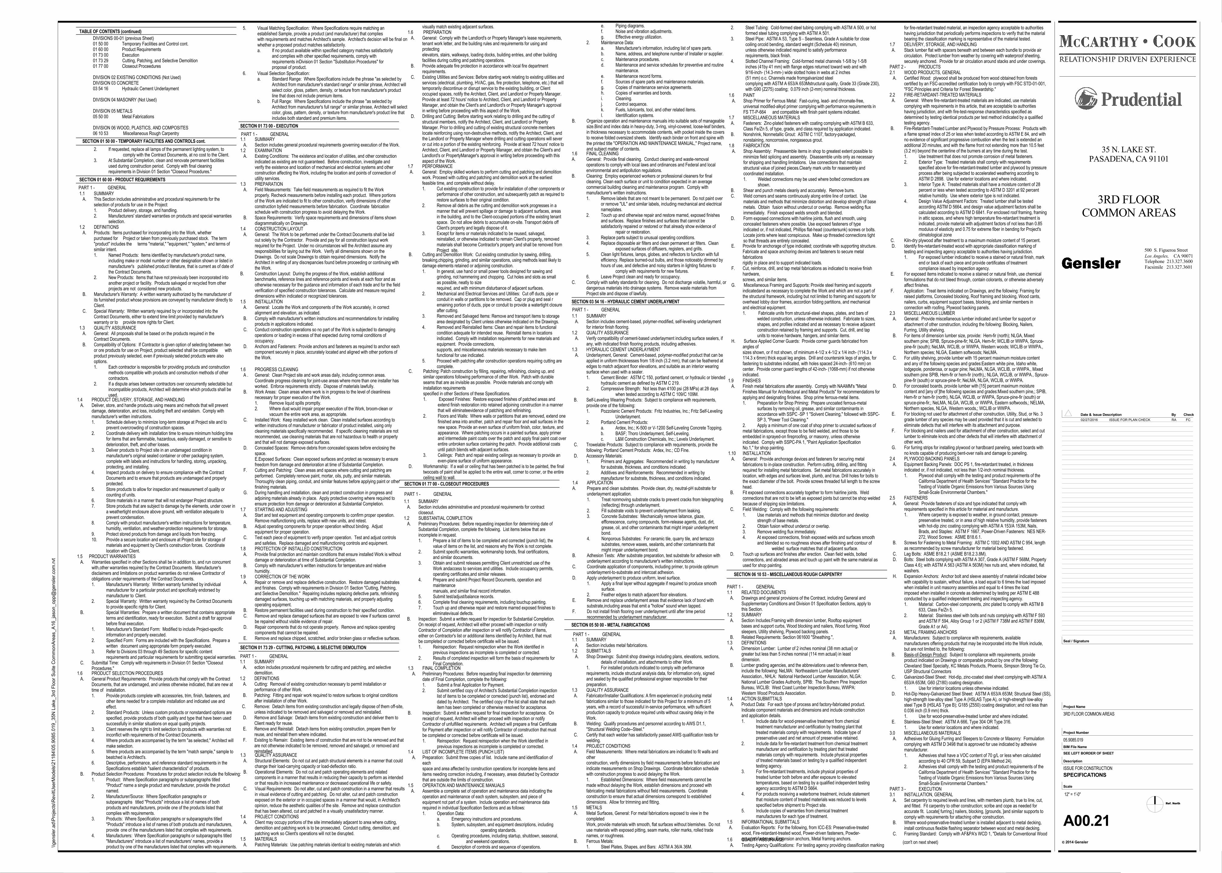
SECTION 01 73 00 - EXECUTION
SECTION 01 73 29 - CUTTING, PATCHING, & SELECTIVE DEMOLITION
SECTION 01 77 00 - CLOSEOUT PROCEDURES
SECTION 03 54 16 - HYDRAULIC CEMENT UNDERLAYMENT
SECTION 05 50 00 - METAL FABRICATIONS
TABLE OF CONTENTS (continued)
SECTION 01 60 00 - PRODUCT REQUIREMENTS
1.1 SUMMARY A. This Section includes administrative and procedural requirements for the
selection of products for use in the Project:1. Product delivery, storage, and handling.2. Manufacturers' standard warranties on products and special warranties
selection.1.2 DEFINITIONS A. Products: Items purchased for incorporating into the Work, whether
purchased for Project or taken from previously purchased stock. The term"product" includes the terms "material," "equipment," "system," and terms ofsimilar intent.1. Named Products: Items identified by manufacturer's product name,
including make or model number or other designation shown or listed inmanufacturer's published product literature, that is current as of date ofthe Contract Documents.
2. New Products: Items that have not previously been incorporated into another project or facility. Products salvaged or recycled from other projects are not considered new products.
B. Manufacturer's Warranty: A written warranty authorized by the manufacturer ofits furnished product whose provisions are conveyed by manufacturer directly toClient.
C. Special Warranty: Written warranty required by or incorporated into theContract Documents, either to extend time limit provided by manufacturer'swarranty or to provide more rights for Client.
1.3 QUALITY ASSURANCE A. General: All proposals shall be based on the products required in the
Contract Documents. B. Compatibility of Options: If Contractor is given option of selecting between two
or ore products for use on Project, product selected shall be compatible withproduct previously selected, even if previously selected products were alsooptions.1. Each contractor is responsible for providing products and construction
methods compatible with products and construction methods of other contractors.
2. If a dispute arises between contractors over concurrently selectable butincompatible products, Architect will determine which products shall beused.
DIVISIONS 00-01 (previous Sheet)01 50 00 Temporary Facilities and Control cont.01 60 00 Product Requirements01 73 00 Execution01 73 29 Cutting, Patching, and Selective Demolition01 77 00 Closeout Proceedures
DIVISION 02 EXISTING CONDITIONS (Not Used)DIVISION 03 CONCRETE03 54 16 Hydraulic Cement Underlayment
DIVISION 04 MASONRY (Not Used)
DIVISION 05 METALS05 50 00 Metal Fabrications
DIVISION 06 WOOD, PLASTICS, AND COMPOSITES06 10 53 Miscellaneous Rough Carpentry
1.4 PRODUCT DELIVERY, STORAGE, AND HANDLING A. Deliver, store, and handle products using means and methods that will prevent
damage, deterioration, and loss, including theft and vandalism. Comply withmanufacturer's written instructions.1. Schedule delivery to minimize long-term storage at Project site and to
prevent overcrowding of construction spaces.2. Coordinate delivery with installation time to ensure minimum holding time
for items that are flammable, hazardous, easily damaged, or sensitive todeterioration, theft, and other losses.
3. Deliver products to Project site in an undamaged condition in manufacturer's original sealed container or other packaging system, complete with labels and instructions for handling, storing, unpacking, protecting, and installing.
4. Inspect products on delivery to ensure compliance with the Contract Documents and to ensure that products are undamaged and properly protected.
5. Store products to allow for inspection and measurement of quality or counting of units.
6. Store materials in a manner that will not endanger Project structure.7. Store products that are subject to damage by the elements, under cover in
a weathertight enclosure above ground, with ventilation adequate to prevent condensation.
8. Comply with product manufacturer's written instructions for temperature, humidity, ventilation, and weather-protection requirements for storage.
9. Protect stored products from damage and liquids from freezing.10. Provide a secure location and enclosure at Project site for storage of
materials and equipment by Client's construction forces. Coordinate location with Client.
1.5 PRODUCT WARRANTIES A. Warranties specified in other Sections shall be in addition to, and run concurrent
with,other warranties required by the Contract Documents. Manufacturer'sdisclaimers and limitations on product warranties do not relieve Contractor ofobligations under requirements of the Contract Documents.1. Manufacturer's Warranty: Written warranty furnished by individual
manufacturer for a particular product and specifically endorsed by manufacturer to Client.
2. Special Warranty: Written warranty required by the Contract Documents to provide specific rights for Client.
B. Special Warranties: Prepare a written document that contains appropriate terms and identification, ready for execution. Submit a draft for approval before final execution.
1. Manufacturer's Standard Form: Modified to include Project-specific information and properly executed.
2. Specified Form: Forms are included with the Specifications. Prepare a written document using appropriate form properly executed.
3. Refer to Divisions 03 through 49 Sections for specific content requirements and particular requirements for submitting special warranties.
C. Submittal Time: Comply with requirements in Division 01 Section "CloseoutProcedures."
1.6 PRODUCT SELECTION PROCEDURES A. General Product Requirements: Provide products that comply with the Contract
Documents, that are undamaged, and unless otherwise indicated, that are new at time of installation.1. Provide products complete with accessories, trim, finish, fasteners, and
other items needed for a complete installation and indicated use and effect.
2. Standard Products: Unless custom products or nonstandard options arespecified, provide products of both quality and type that have been usedsuccessfully in similar situations on equal quality projects.
3. Client reserves the right to limit selection to products with warranties not inconflict with requirements of the Contract Documents.
4. Where products are accompanied by the term "as selected," Architect will make selection.
5. Where products are accompanied by the term "match sample," sample to beatched is Architect's.
6. Descriptive, performance, and reference standard requirements in theSpecifications establish "salient characteristics" of products.
B. Product Selection Procedures: Procedures for product selection include the following:1. Product: Where Specification paragraphs or subparagraphs titled
"Product" name a single product and manufacturer, provide the product named.
2. Manufacturer/Source: Where Specification paragraphs or subparagraphs titled "Products" introduce a list of names of both products and manufacturers, provide one of the products listed that complies with requirements.
3. Products: Where Specification paragraphs or subparagraphs titled "Products" introduce a list of names of both products and manufacturers, provide one of the manufacturers listed that complies with requirements.
4. Manufacturers: Where Specification paragraphs or subparagraphs titled"Manufacturers" introduce a list of manufacturers' names, provide a product by one of the manufacturers listed that complies with requirements.
6. Visual Selection Specification:a. Standard Range: Where Specifications include the phrase "as selected by
Architect from manufacturer's standard range" or similar phrase, Architect willselect color, gloss, pattern, density, or texture from manufacturer's productline that does not include premium items.
b. Full Range: Where Specifications include the phrase "as selected byArchitect from manufacturer's full range" or similar phrase, Architect will selectcolor, gloss, pattern, density, or texture from manufacturer's product line thatincludes both standard and premium items.
1.1 SUMMARY A. Section includes general procedural requirements governing execution of the Work.1.2 EXAMINATION A. Existing Conditions: The existence and location of utilities, and other construction
indicated as existing are not guaranteed. Before construction, investigate andverify the existence and location of mechanical and electrical systems and otherconstruction affecting the Work, including the location and points of connection ofutility services.
1.3 PREPARATION A. Field Measurements: Take field measurements as required to fit the Work
properly. Recheck measurements before installing each product. Where portionsof the Work are indicated to fit to other construction, verify dimensions of otherconstruction byfield measurements before fabrication. Coordinate fabricationschedule with construction progress to avoid delaying the Work.
B. Space Requirements: Verify space requirements and dimensions of items showndiagrammatically on Drawings.
1.4 CONSTRUCTION LAYOUT A. General: The Work to be performed under the Contract Documents shall be laid
out solely by the Contractor. Provide and pay for all construction layout workrequired for the Project. Under no circumstances will the Architect assume anyresponsibilities for laying out the Work. Verify all dimensions shown on theDrawings. Do not scale Drawings to obtain required dimensions. Notify theArchitect in writing of any discrepancies found before proceeding or continuing withthe Work.
B. Construction Layout: During the progress of the Work, establish additionalbenchmarks, reference lines and reference points and levels at each floor and asotherwise necessary for the guidance and information of each trade and for the fieldverification of specified construction tolerances. Calculate and measure requireddimensions within indicated or recognized tolerances.
1.5 INSTALLATION A. General: Locate the Work and components of the Work accurately, in correct
alignment and elevation, as indicated. B. Comply with manufacturer's written instructions and recommendations for installing
products in applications indicated. C. Conduct construction operations so no part of the Work is subjected to damaging
operations or loading in excess of that expected during normal conditions ofoccupancy.
D. Anchors and Fasteners: Provide anchors and fasteners as required to anchor eachcomponent securely in place, accurately located and aligned with other portions ofthe Work.
1.6 PROGRESS CLEANING A . General: Clean Project site and work areas daily, including common areas.
Coordinate progress cleaning for joint-use areas where more than one installer hasworked. Enforce requirements strictly. Dispose of materials lawfully.
B. Work Areas: Clean areas where work is in progress to the level of cleanlinessnecessary for proper execution of the Work.1. Remove liquid spills promptly.2. Where dust would impair proper execution of the Work, broom-clean or
vacuum the entire work area, as appropriate. C. Installed Work: Keep installed work clean. Clean installed surfaces according to
written instructions of manufacturer or fabricator of product installed, using onlycleaning materials specifically recommended. If specific cleaning materials are notrecommended, use cleaning materials that are not hazardous to health or propertyand that will not damage exposed surfaces.
D. Concealed Spaces: Remove debris from concealed spaces before enclosing thespace.E.Exposed Surfaces: Clean exposed surfaces and protect as necessary to ensurefreedom from damage and deterioration at time of Substantial Completion.
F. Cutting and Patching: Clean areas and spaces where cutting and patching areperformed. Completely remove paint, mortar, oils, putty, and similar materials.Thoroughly clean piping, conduit, and similar features before applying paint or otherfinishing materials.
G. During handling and installation, clean and protect construction in progress andadjoining materials already in place. Apply protective covering where required toensure protection from damage or deterioration at Substantial Completion.
1.7 STARTING AND ADJUSTING A. Start and test equipment and operating components to confirm proper operation.
Remove malfunctioning units, replace with new units, and retest. B. Adjust operating components for proper operation without binding. Adjust
equipment for proper operation. C. Test each piece of equipment to verify proper operation. Test and adjust controls
and safeties. Replace damaged and malfunctioning controls and equipment.1.8 PROTECTION OF INSTALLED CONSTRUCTION A. Provide final protection and maintain conditions that ensure installed Work is without
damage or deterioration at time of Substantial Completion. B. Comply with manufacturer's written instructions for temperature and relative
humidity.1.9 CORRECTION OF THE WORK A. Repair or remove and replace defective construction. Restore damaged substrates
and finishes. Comply with requirements in Division 01 Section "Cutting, Patching,and Selective Demolition." Repairing includes replacing defective parts, refinishingdamaged surfaces, touching up with matching materials, and properly adjustingoperating equipment.
B. Restore permanent facilities used during construction to their specified condition. C. Remove and replace damaged surfaces that are exposed to view if surfaces cannot
be repaired without visible evidence of repair. D. Repair components that do not operate properly. Remove and replace operating
components that cannot be repaired. E. Remove and replace chipped, scratched, and/or broken glass or reflective surfaces.
1.1 SUMMARY A. ection includes procedural requirements for cutting and patching, and selective
demolition.1.2 DEFINITIONS A. Cutting: Removal of existing construction necessary to permit installation or
performance of other Work. B. Patching: Fitting and repair work required to restore surfaces to original conditions
after installation of other Work. C. Remove: Detach items from existing construction and legally dispose of them off-site,
unless indicated to be removed and salvaged or removed and reinstalled. D. Remove and Salvage: Detach items from existing construction and deliver them to
Client ready for reuse. E. Remove and Reinstall: Detach items from existing construction, prepare them for
reuse, and reinstall them where indicated. F. Existing to Remain: Existing items of construction that are not to be removed and that
are not otherwise indicated to be removed, removed and salvaged, or removed andreinstalled.
1.3 QUALITY ASSURANCE A. Structural Elements: Do not cut and patch structural elements in a manner that could
change their load-carrying capacity or load-deflection ratio. B. Operational Elements: Do not cut and patch operating elements and related
components in a manner that results in reducing their capacity to perform as intendedor that results in increased maintenance or decreased operational life or safety.
C. Visual Requirements: Do not alter, cut and patch construction in a manner that resultsin visual evidence of cutting and patching. Do not alter, cut and patch constructionexposed on the exterior or in occupied spaces in a manner that would, in Architect'sopinion, reduce the aesthetic qualities of the site. Remove and replace constructionthat has been altered, cut and patched in a visually unsatisfactory manner.
1.4 PROJECT CONDITIONS A. Client may occupy portions of the site immediately adjacent to area where cutting,
demolition and patching work is to be prosecuted. Conduct cutting, demolition, andpatching work so Client's operations will not be disrupted.
1.5 MATERIALS A. Patching Materials: Use patching materials identical to existing materials and which
A. General: Comply with the Landlord's or Property Manager's lease requirements,tenant work letter, and the building rules and requirements for using andprotectingelevators, stairs, walkways, loading docks, building entries, and other buildingfacilities during cutting and patching operations.
B. Provide adequate fire protection in accordance with local fire departmentrequirements.
C. Existing Utilities and Services: Before starting work relating to existing utilities andservices (electrical, plumbing, HVAC, gas, fire protection, telephone, etc.) that willtemporarily discontinue or disrupt service to the existing building, or Clientoccupied spaces, notify the Architect, Client, and Landlord or Property Manager.Provide at least 72 hours' notice to Architect, Client, and Landlord or PropertyManager, and obtain the Client's and Landlord's or Property Manager's approvalin writing before proceeding with this aspect of the Work.
D. Drilling and Cutting: Before starting work relating to drilling and the cutting ofstructural members, notify the Architect, Client, and Landlord or PropertyManager. Prior to drilling and cutting of existing structural concrete memberslocate reinforcing using non-destructive methods, notify the Architect, Client, andthe Landlord or Property Manager where drilling and cutting operations will severor cut into a portion of the existing reinforcing. Provide at least 72 hours' notice toArchitect, Client, and Landlord or Property Manager, and obtain the Client's andLandlord's or PropertyManager's approval in writing before proceeding with thisaspect of the Work.
1.7 PERFORMANCE A. General: Employ skilled workers to perform cutting and patching and demolition
work. Proceed with cutting and patching and demolition work at the earliestfeasible time, and complete without delay.1. Cut existing construction to provide for installation of other components or
performance of other construction, and subsequently patch as required torestore surfaces to their original condition.
2. Remove all debris as the cutting and demolition work progresses in a manner that will prevent spillage or damage to adjacent surfaces, areasin the building, and to the Client-occupied portions of the existing tenantspace. Do not allow debris to accumulate on-site. Transport debris off Client's property and legally dispose of it.
3. Except for items or materials indicated to be reused, salvaged, reinstalled, or otherwise indicated to remain Client's property, removed materials shall become Contractor's property and shall be removed fromProject site.
B. Cutting and Demolition Work: Cut existing construction by sawing, drilling, breaking,chipping, grinding, and similar operations, using methods least likely todamage elements retained or adjoining construction.1. In general, use hand or small power tools designed for sawing and
grinding, not hammering and chopping. Cut holes and slots as small as possible, neatly to sizerequired, and with minimum disturbance of adjacent surfaces.
2. Mechanical and Electrical Services and Utilities: Cut off ducts, pipe or conduit in walls or partitions to be removed. Cap or plug and seal remaining portion of ducts, pipe or conduit to provide a watertight closureafter cutting.
3. Removed and Salvaged Items: Remove and transport items to storage area designated by Client unless otherwise indicated on the Drawings.
4. Removed and Reinstalled Items: Clean and repair items to functional condition adequate for intended reuse. Reinstall items in locations indicated. Comply with installation requirements for new materials andequipment. Provide connections,supports, and miscellaneous materials necessary to make item functional for use indicated.
5. Proceed with patching after construction operations requiring cutting arecomplete.
C. Patching: Patch construction by filling, repairing, refinishing, closing up, andsimilar operations following performance of other Work. Patch with durableseams that are as invisible as possible. Provide materials and comply withinstallation requirementsspecified in other Sections of these Specifications.1. Exposed Finishes: Restore exposed finishes of patched areas and
extend finish restoration into retained adjoining construction in a mannerthat will eliminateevidence of patching and refinishing.
2. Floors and Walls: Where walls or partitions that are removed, extend onefinished area into another, patch and repair floor and wall surfaces in thenew space. Provide an even surface of uniform finish, color, texture, andappearance. Where patching occurs in a painted surface, apply primer and intermediate paint coats over the patch and apply final paint coat overentire unbroken surface containing the patch. Provide additional coats until patch blends with adjacent surfaces.
3. Ceilings: Patch and repair existing ceilings as necessary to provide aneven-plane surface of uniform appearance.
D. Workmanship: If a wall or ceiling that has been patched is to be painted, the finaltwocoats of paint shall be applied to the entire wall, corner to corner, or the entireceiling wall to wall.
1.1 SUMMARY A. Section includes administrative and procedural requirements for contract
closeout.1.2 SUBSTANTIAL COMPLETION A. Preliminary Procedures: Before requesting inspection for determining date of
Substantial Completion, complete the following. List items below that areincomplete in request.1. Prepare a list of items to be completed and corrected (punch list), the
value of items on the list, and reasons why the Work is not complete.2. Submit specific warranties, workmanship bonds, final certifications,
and similar documents.3. Obtain and submit releases permitting Client unrestricted use of the
Work andaccess to services and utilities. Include occupancy permits,operating certificates,and similar releases.
4. Prepare and submit Project Record Documents, operation and maintenancemanuals, and similar final record information.
5. Submit test/adjust/balance records.6. Complete final cleaning requirements, including touchup painting.7. Touch up and otherwise repair and restore marred exposed finishes to
eliminatevisual defects. B. Inspection: Submit a written request for inspection for Substantial Completion.
On receipt of request, Architect will either proceed with inspection or notifyContractor of Completion after inspection or will notify Contractor of items,either on Contractor's list or additional items identified by Architect, that mustbe completed or corrected before certificate will be issued.1. Reinspection: Request reinspection when the Work identified in
previous inspections as incomplete is completed or corrected.2. Results of completed inspection will form the basis of requirements for
Final Completion.1.3 FINAL COMPLETION A. Preliminary Procedures: Before requesting final inspection for determining
date of Final Completion, complete the following:1. Submit a final Application for Payment.2. Submit certified copy of Architect's Substantial Completion inspection
list of items to be completed or corrected (punch list), endorsed anddated by Architect. The certified copy of the list shall state that eachitem has been completed or otherwise resolved for acceptance.
B. Inspection: Submit a written request for final inspection for acceptance. Onreceipt of request, Architect will either proceed with inspection or notifyContractor of unfulfilled requirements. Architect will prepare a final Certificatefor Payment after inspection or will notify Contractor of construction that mustbe completed or corrected before certificate will be issued.1. Reinspection: Request reinspection when the Work identified in
previous inspections as incomplete is completed or corrected.1.4 LIST OF INCOMPLETE ITEMS (PUNCH LIST) A. Preparation: Submit three copies of list. Include name and identification of
eachspace and area affected by construction operations for incomplete items anditems needing correction including, if necessary, areas disturbed by Contractorthat are outside the limits of construction.
1.5 OPERATION AND MAINTENANCE MANUALS A. Assemble a complete set of operation and maintenance data indicating the
operation and maintenance of each system, subsystem, and piece ofequipment not part of a system. Include operation and maintenance datarequired in individual Specification Sections and as follows:1. Operation Data:
a. Emergency instructions and procedures.b. System, subsystem, and equipment descriptions, including
operating standards.c. Operating procedures, including startup, shutdown, seasonal,
and weekend operations.d. Description of controls and sequence of operations.
e. Piping diagrams.f. Noise and vibration adjustments.g. Effective energy utilization.
2. Maintenance Data:a. Manufacturer's information, including list of spare parts.b. Name, address, and telephone number of Installer or supplier.c. Maintenance procedures.d. Maintenance and service schedules for preventive and routine
maintenance.e. Maintenance record forms.f. Sources of spare parts and maintenance materials.g. Copies of maintenance service agreements.h. Copies of warranties and bonds.i. Cleaning.j. Control sequence.k. Fuels, lubricants, tool, and other related items.l. Identification systems.
B. Organize operation and maintenance manuals into suitable sets of manageablesize.Bind and index data in heavy-duty, 3-ring, vinyl-covered, loose-leaf binders,in thickness necessary to accommodate contents, with pocket inside the coversto receive folded oversized sheets. Identify each binder on front and spine withthe printed title "OPERATION AND MAINTENANCE MANUAL," Project name, and subject matter of contents.
1.6 FINAL CLEANINGA. General: Provide final cleaning. Conduct cleaning and waste-removal
operations to comply with local laws and ordinances and Federal and localenvironmental and antipollution regulations.
B. Cleaning: Employ experienced workers or professional cleaners for finalcleaning. Clean each surface or unit to condition expected in an averagecommercial building cleaning and maintenance program. Comply withmanufacturer's written instructions.1. Remove labels that are not meant to be permanent. Do not paint over
or remove "UL" and similar labels, including mechanical and electrical nameplates.
2. Touch up and otherwise repair and restore marred, exposed finishes and surfaces. Replace finishes and surfaces that cannot be satisfactorily repaired or restored or that already show evidence of
repair or restoration.3. Replace parts subject to unusual operating conditions.4. Replace disposable air filters and clean permanent air filters. Clean
exposed surfaces of diffusers, registers, and grills.5. Clean light fixtures, lamps, globes, and reflectors to function with full
efficiency. Replace burned-out bulbs, and those noticeably dimmed by hours of use, and defective and noisy starters in lighting fixtures to
comply with requirements for new fixtures.6. Leave Project clean and ready for occupancy.
C. Comply with safety standards for cleaning. Do not discharge volatile, harmful, ordangerous materials into drainage systems. Remove waste materials fromProject site and dispose of lawfully.
1.1 SUMMARY A. Section includes cement-based, polymer-modified, self-leveling underlayment
for interior finish flooring.1.2 QUALITY ASSURANCE A. Verify compatibility of cement-based underlayment including surface sealers, if
any, with indicated finish flooring products, including adhesives.1.3 HYDRAULIC CEMENT UNDERLAYMENT A. Underlayment, General: Cement-based, polymer-modified product that can be
applied in uniform thicknesses from 1/8 inch (3.2 mm), that can be feathered atedges to match adjacent floor elevations, and suitable as an interior wearingsurface when used with a sealer.1. Cement Binder: ASTM C 150, portland cement, or hydraulic or blended
hydraulic cement as defined by ASTM C 219.2. Compressive Strength: Not less than 4100 psi (28 MPa) at 28 days
when tested according to ASTM C 109/C 109M. B. Self-Leveling Wearing Products: Subject to compliance with requirements,
provide one of the following:1. Pozzolanic Cement Products: Fritz Industries, Inc.; Fritz Self-Leveling
Underlayment.2. Portland Cement Products:
a. Ardex, Inc.; K-500 or V-1200 Self-Leveling Concrete Topping.b. BASF; Thoro Underlayment, Self-Leveling.c. L&M Construction Chemicals, Inc.; Levelx Underlayment.
C. Trowelable Products: Subject to compliance with requirements, provide thefollowing: Portland Cement Products: Ardex, Inc.; CD Fine.
D. Accessory Materials:1. Primers and Aggregates: Recommended in writing by manufacturer
for substrate, thickness, and conditions indicated.2. Additives and Reinforcements: Recommended in writing by
manufacturer for substrate, thickness, and conditions indicated.1.4 APPLICATIONA. Prepare and clean substrates. Provide clean, dry, neutral-pH substrate for
underlayment application.1. Treat nonmoving substrate cracks to prevent cracks from telegraphing
(reflecting) through underlayment.2. Fill substrate voids to prevent underlayment from leaking.3. Concrete Substrates: Mechanically remove laitance, glaze,
efflorescence, curing compounds, form-release agents, dust, dirt, grease, oil, and other contaminants that might impair underlayment bond.
4. Nonporous Substrates: For ceramic tile, quarry tile, and terrazzo substrates, remove waxes, sealants, and other contaminants that might impair underlayment bond.
B. Adhesion Tests: After substrate preparation, test substrate for adhesion withunderlayment according to manufacturer's written instructions.
C. Coordinate application of components, including primer, to provide optimumunderlayment-to-substrate and intercoat adhesion.
D. Apply underlayment to produce uniform, level surface.1. Apply a final layer without aggregate if required to produce smooth
surface.2. Feather edges to match adjacent floor elevations.
E. Remove and replace underlayment areas that evidence lack of bond withsubstrate,including areas that emit a "hollow" sound when tapped.
F. Do not install finish flooring over underlayment until after time period recommended by underlayment manufacturer.
1.1 SUMMARY A. Section includes metal fabrications.1.2 SUBMITTALS A. Shop Drawings: Submit shop drawings including plans, elevations, sections,
details of installation, and attachments to other Work.1. For installed products indicated to comply with performancerequirements, include structural analysis data, for information only, signedand sealed by the qualified professional engineer responsible for theirpreparation.
1.3 QUALITY ASSURANCE A. Fabricator/Installer Qualifications: A firm experienced in producing metal
fabrications similar to those indicated for this Project for a minimum of 5years, with a record of successful in-service performance, with sufficientproduction capacity to produce required units without causing delay in theWork.
B. Welding: Qualify procedures and personnel according to AWS D1.1,"Structural Welding Code--Steel."
C. Certify that each welder has satisfactorily passed AWS qualification tests forwelding.
1.4 PROJECT CONDITIONS A. Field Measurements: Where metal fabrications are indicated to fit walls and
otherconstruction, verify dimensions by field measurements before fabrication andindicate measurements on Shop Drawings. Coordinate fabrication schedulewith construction progress to avoid delaying the Work.1. Established Dimensions: Where field measurements cannot bemade without delaying the Work, establish dimensions and proceed withfabricating metal fabrications without field measurements. Coordinateconstruction to ensure that actual dimensions correspond to establisheddimensions. Allow for trimming and fitting.
1.5 METALS A. Metal Surfaces, General: For metal fabrications exposed to view in the
completedWork, provide materials with smooth, flat surfaces without blemishes. Do notuse materials with exposed pitting, seam marks, roller marks, rolled tradenames, or roughness.
B. Ferrous Metals:1. Steel Plates, Shapes, and Bars: ASTM A 36/A 36M.
2. Steel Tubing: Cold-formed steel tubing complying with ASTM A 500, or hotformed steel tubing complying with ASTM A 501.
3. Steel Pipe: ASTM A 53, Type S - Seamless, Grade A suitable for close coiling orcold bending, standard weight (Schedule 40) minimum,unless otherwise indicated required to satisfy performancerequirements, black finish.
4. Slotted Channel Framing: Cold-formed metal channels 1-5/8 by 1-5/8 inches (41by 41 mm) with flange edges returned toward web and with9/16-inch- (14.3-mm-) wide slotted holes in webs at 2 inches(51 mm) o.c. Channels made fromgalvanized steelcomplying with ASTM A 653/A 653Mstructural quality, Grade 33 (Grade 230),with G90 (Z275) coating; 0.079 inch (2-mm) nominal thickness.
1.6 PAINT A. Shop Primer for Ferrous Metal: Fast-curing, lead- and chromate-free,
universal modified-alkyd primer complying with performance requirements inFS TT-P-664 and compatible with finish paint systems indicated.
1.7 MISCELLANEOUS MATERIALS A. Fasteners: Zinc-plated fasteners with coating complying with ASTM B 633,
Class Fe/Zn 5, of type, grade, and class required by application indicated. B. Nonshrink, Nonmetallic Grout: ASTM C 1107, factory-packaged,
nonstaining, noncorrosive, nongaseous grout.1.8 FABRICATION A. Shop Assembly: Preassemble items in shop to greatest extent possible to
minimize field splicing and assembly. Disassemble units only as necessaryfor shipping and handling limitations. Use connections that maintainstructural value of joined pieces.Clearly mark units for reassembly andcoordinated installation.1. Welded connections may be used where bolted connections are
shown. B. Shear and punch metals cleanly and accurately. Remove burrs. C. Weld corners and seams continuously along entire line of contact. Use
materials and methods that minimize distortion and develop strength of basemetals. Obtain fusion without undercut or overlap. Remove welding fluximmediately. Finish exposed welds smooth and blended.
D. Form exposed connections with hairline joints, flush and smooth, usingconcealed fasteners where possible. Use exposed fasteners of typeindicated or, if not indicated, Phillips flat-head (countersunk) screws or bolts.Locate joints where least conspicuous. Make up threaded connections tightso that threads are entirely concealed.
E. Provide for anchorage of type indicated; coordinate with supporting structure.Fabricate and space anchoring devices and fasteners to secure metalfabricationsrigidly in place and to support indicated loads.
F. Cut, reinforce, drill, and tap metal fabrications as indicated to receive finishhardware,screws, and similar items.
G. Miscellaneous Framing and Supports: Provide steel framing and supportsindicatedand as necessary to complete the Work and which are not a part ofthe structural framework, including but not limited to framing and supports foroverhead lobby door frames, accordion folding partitions, and mechanicaland electrical equipment.1. Fabricate units from structural-steel shapes, plates, and bars of
welded construction, unless otherwise indicated. Fabricate to sizes, shapes, and profiles indicated and as necessary to receive adjacent construction retained by framing and supports. Cut, drill, and tap units to receive hardware, hangers, and similar items.
H. Surface Applied Corner Guards: Provide corner guards fabricated fromangles ofsizes shown, or if not shown, of minimum 4-1/2 x 4-1/2 x 1/4 inch- (114.3 x114.3 x 6mm) thick equal leg angles. Drill and countersink legs of angles, forfastening to substrates indicated, with holes spaced 24-inch- (610 mm) oncenter. Provide corner guard lengths of 42-inch- (1068-mm) if not otherwiseindicated.
1.9 FINISHES A. Finish metal fabrications after assembly. Comply with NAAMM's "Metal
Finishes Manual for Architectural and Metal Products" for recommendations forapplying and designating finishes. Shop prime ferrous-metal items.1. Preparation for Shop Priming: Prepare uncoated ferrous-metal
surfaces by removing oil, grease, and similar contaminants in accordance with SSPC -SP 1 "Solvent Cleaning," followed with SSPC-SP 3, "Power Tool Cleaning."
2. Apply a minimum of one coat of shop primer to uncoated surfaces of metal fabrications, except those to be field welded, and those to be embedded in sprayed-on fireproofing, or masonry, unless otherwise indicated. Comply with SSPC-PA 1, "Paint Application Specification No.1," for shop painting.
1.10 INSTALLATION A. General: Provide anchorage devices and fasteners for securing metal
fabrications to in-place construction. Perform cutting, drilling, and fittingrequired for installing metal fabrications. Set metal fabrications accurately inlocation, with edges and surfaces level, plumb, and true. Drill holes for bolts tothe exact diameter of the bolt. Provide screws threaded full length to the screwhead.
B. Fit exposed connections accurately together to form hairline joints. Weldconnections that are not to be left as exposed joints but cannot be shop weldedbecause of shipping size limitations.
C. Field Welding: Comply with the following requirements:1. Use materials and methods that minimize distortion and develop
strength of base metals.2. Obtain fusion without undercut or overlap.3. Remove welding flux immediately.4. At exposed connections, finish exposed welds and surfaces smooth
and blended so no roughness shows after finishing and contour of welded surface matches that of adjacent surface.
D. Touch up surfaces and finishes after erection. Clean field welds, boltedconnections, and abraded areas and touch up paint with the same material asused for shop painting.
PART 1 - GENERAL1.1 RELATED DOCUMENTS A. Drawings and general provisions of the Contract, including General and
Supplementary Conditions and Division 01 Specification Sections, apply tothis Section.
1.2 SUMMARY A. Section Includes:Framing with dimension lumber, Rooftop equipment
bases and support curbs, Wood blocking and nailers, Wood furring, Woodsleepers, Utility shelving, Plywood backing panels.
B. Related Requirements: Section 061600 "Sheathing.",1.3 DEFINITIONS A. Dimension Lumber: Lumber of 2 inches nominal (38 mm actual) or
greater but less than 5 inches nominal (114 mm actual) in leastdimension.
B. Lumber grading agencies, and the abbreviations used to reference them,include the following: NeLMA: Northeastern Lumber Manufacturers'Association., NHLA: National Hardwood Lumber Association, NLGA:National Lumber Grades Authority, SPIB: The Southern Pine InspectionBureau, WCLIB: West Coast Lumber Inspection Bureau, WWPA:Western Wood Products Association.
1.4 ACTION SUBMITTALS A. Product Data: For each type of process and factory-fabricated product.
Indicate component materials and dimensions and include constructionand application details.1. Include data for wood-preservative treatment from chemical
treatment manufacturer and certification by treating plant that treated materials comply with requirements. Indicate type of preservative used and net amount of preservative retained.
2. Include data for fire-retardant treatment from chemical treatment manufacturer and certification by treating plant that treated materials comply with requirements. Include physical properties of treated materials based on testing by a qualified independent testing agency.
3. For fire-retardant treatments, include physical properties of treated lumber both before and after exposure to elevated temperatures, based on testing by a qualified independent testingagency according to ASTM D 5664.
4. For products receiving a waterborne treatment, include statementthat moisture content of treated materials was reduced to levels specified before shipment to Project site.
5. Include copies of warranties from chemical treatment manufacturers for each type of treatment.
1.5 INFORMATIONAL SUBMITTALS A. Evaluation Reports: For the following, from ICC-ES: Preservative-treated
wood, Fire-retardant-treated wood, Power-driven fasteners, Powder-actuated fasteners, Expansion anchors, Metal framing anchors.
for fire-retardant treated material, an inspection agency acceptable to authoritieshaving jurisdiction that periodically performs inspections to verify that the materialbearing the classification marking is representative of the material tested.
1.7 DELIVERY, STORAGE, AND HANDLING A. Stack lumber flat with spacers beneath and between each bundle to provide air
circulation. Protect lumber from weather by covering with waterproof sheeting,securely anchored. Provide for air circulation around stacks and under coverings.
PART 2 - PRODUCTS2.1 WOOD PRODUCTS, GENERAL A. Certified Wood: plywood shall be produced from wood obtained from forests
certified by an FSC-accredited certification body to comply with FSC STD-01-001,"FSC Principles and Criteria for Forest Stewardship."
2.2 FIRE-RETARDANT-TREATED MATERIALS A. General: Where fire-retardant-treated materials are indicated, use materials
complying with requirements in this article, that are acceptable to authoritieshaving jurisdiction, and with fire-test-response characteristics specified asdetermined by testing identical products per test method indicated by a qualifiedtesting agency.
B. Fire-Retardant-Treated Lumber and Plywood by Pressure Process: Products witha flame spread index of 25 or less when tested according to ASTM E 84, and withno evidence of significant progressive combustion when the test is extended anadditional 20 minutes, and with the flame front not extending more than 10.5 feet(3.2 m) beyond the centerline of the burners at any time during the test.1. Use treatment that does not promote corrosion of metal fasteners.2. Exterior Type: Treated materials shall comply with requirements
specified above for fire-retardant-treated lumber and plywood by pressureprocess after being subjected to accelerated weathering according to ASTM D 2898. Use for exterior locations and where indicated.
3. Interior Type A: Treated materials shall have a moisture content of 28 percent or less when tested according to ASTM D 3201 at 92 percent relative humidity. Use where exterior type is not indicated.
4. Design Value Adjustment Factors: Treated lumber shall be tested according ASTM D 5664, and design value adjustment factors shall be calculated according to ASTM D 6841. For enclosed roof framing, framingin attic spaces, and where high temperature fire-retardant treatment is indicated, provide material with adjustment factors of not less than 0.85modulus of elasticity and 0.75 for extreme fiber in bending for Project's climatological zone
C. Kiln-dry plywood after treatment to a maximum moisture content of 15 percent. D. Identify fire-retardant-treated wood with appropriate classification marking of
testing and inspecting agency acceptable to authorities having jurisdiction.1. For exposed lumber indicated to receive a stained or natural finish, mark
end or back of each piece and provide certificates of treatment compliance issued by inspection agency.
E. For exposed items indicated to receive a stained or natural finish, use chemicalformulations that do not bleed through, contain colorants, or otherwise adverselyaffect finishes.
F. Application: Treat items indicated on Drawings, and the following: Framing for raised platforms, Concealed blocking, Roof framing and blocking, Wood cants,nailers, curbs, equipment support bases, blocking, and similar members inconnection with roofing, Plywood backing panels.
2.3 MISCELLANEOUS LUMBER A. General: Provide miscellaneous lumber indicated and lumber for support or
attachment of other construction, including the following: Blocking, Nailers,Furring, Utility shelving.
B. For items of dimension lumber size, provide: Hem-fir (north); NLGA, Mixedsouthern pine; SPIB, Spruce-pine-fir; NLGA, Hem-fir; WCLIB or WWPA, Spruce-pine-fir (south); NeLMA, WCLIB, or WWPA, Western woods; WCLIB or WWPA.,Northern species; NLGA, Eastern softwoods; NeLMA.
C. For utility shelving, provide lumber with 15 percent maximum moisture contentand any of the following species and grades:Eastern white pine, Idaho white,lodgepole, ponderosa, or sugar pine; NeLMA, NLGA, WCLIB, or WWPA., Mixedsouthern pine SPIB, Hem-fir or hem-fir (north),; NLGA, WCLIB, or WWPA., Spruce-pine-fir (south) or spruce-pine-fir; NeLMA, NLGA, WCLIB, or WWPA.
D. For concealed boards, provide lumber with [15] percent maximum moisturecontent and [any of ]the following species and grades:Mixed southern pine,; SPIB,Hem-fir or hem-fir (north), NLGA, WCLIB, or WWPA, Spruce-pine-fir (south) orspruce-pine-fir,; NeLMA, NLGA, WCLIB, or WWPA, Eastern softwoods,; NELMA,Northern species, NLGA, Western woods,; WCLIB or WWPA.
E. For blocking not used for attachment of other construction, Utility, Stud, or No. 3grade lumber of any species may be used provided that it is cut and selected toeliminate defects that will interfere with its attachment and purpose.
F. For blocking and nailers used for attachment of other construction, select and cutlumber to eliminate knots and other defects that will interfere with attachment ofother work.
G. For furring strips for installing plywood or hardboard paneling, select boards withno knots capable of producing bent-over nails and damage to paneling.
2.4 PLYWOOD BACKING PANELS A. Equipment Backing Panels: DOC PS 1, fire-retardant treated, in thickness
indicated or, if not indicated, not less than 1/2-inch nominal thickness.1. Plywood shall comply with the testing and product requirements of the
California Department of Health Services' "Standard Practice for the Testing of Volatile Organic Emissions from Various Sources Using Small-Scale Environmental Chambers."
2.5 FASTENERS A. General: Provide fasteners of size and type indicated that comply with
requirements specified in this article for material and manufacture.1. Where carpentry is exposed to weather, in ground contact, pressure-
preservative treated, or in area of high relative humidity, provide fastenerswith hot-dip zinc coating complying with ASTM A 153/A 153M, Nails, Brads, and Staples: ASTM F 1667, Power-Driven Fasteners: NES NER-272, Wood Screws: ASME B18.6.1.
B. Screws for Fastening to Metal Framing: ASTM C 1002 AND ASTM C 954, lengthas recommended by screw manufacturer for material being fastened.
C. Lag Bolts: ASME B18.2.1 (ASME B18.2.3.8M). D. Bolts: Steel bolts complying with ASTM A 307, Grade A (ASTM F 568M, Property
Class 4.6); with ASTM A 563 (ASTM A 563M) hex nuts and, where indicated, flatwashers.
H. Expansion Anchors: Anchor bolt and sleeve assembly of material indicated belowwith capability to sustain, without failure, a load equal to 6 times the load imposedwhen installed in unit masonry assemblies and equal to 4 times the loadimposed when installed in concrete as determined by testing per ASTM E 488conducted by a qualified independent testing and inspecting agency.1. Material: Carbon-steel components, zinc plated to comply with ASTM B
633, Class Fe/Zn 5.2. Material: Stainless steel with bolts and nuts complying with ASTM F 593
and ASTM F 594, Alloy Group 1 or 2 (ASTM F 738M and ASTM F 836M, Grade A1 or A4).
2.6 METAL FRAMING ANCHORS A. Manufacturers: Subject to compliance with requirements, available
manufacturers offering products that may be incorporated into the Work include,but are not limited to, the following:
B. Basis-of-Design Product: Subject to compliance with requirements, provideproduct indicated on Drawings or comparable product by one of the following:Cleveland Steel Specialty, KC Metals Products, Phoenix, Simpson Strong Tie Co,USP Structural Connectors
C. Galvanized-Steel Sheet: Hot-dip, zinc-coated steel sheet complying with ASTM A653/A 653M, G60 (Z180) coating designation.1. Use for interior locations unless otherwise indicated.
D. Hot-Dip Heavy-Galvanized Steel Sheet: ASTM A 653/A 653M; Structural Steel (SS),high-strength low-alloy steel Type A (HSLAS Type A), or high-strength low-alloysteel Type B (HSLAS Type B); G185 (Z550) coating designation; and not less than0.036 inch (0.9 mm) thick.1. Use for wood-preservative-treated lumber and where indicated.
E. Stainless-Steel Sheet: ASTM A 666, Type 304 OR Type 316.1. Use for exterior locations and where indicated.
3.0 MISCELLANEOUS MATERIALS A. Adhesives for Gluing Furring and Sleepers to Concrete or Masonry: Formulation
complying with ASTM D 3498 that is approved for use indicated by adhesivemanufacturer.1. Adhesives shall have a VOC content of 70 g/L or less when calculated
according to 40 CFR 59, Subpart D (EPA Method 24).2. Adhesives shall comply with the testing and product requirements of the
California Department of Health Services' "Standard Practice for the Testing of Volatile Organic Emissions from Various Sources Using Small-Scale Environmental Chambers."
PART 3 - EXECUTION3.1 INSTALLATION, GENERAL A. Set carpentry to required levels and lines, with members plumb, true to line, cut,
and fitted. Fit carpentry to other construction; scribe and cope as needed foraccurate fit. Locate[ furring,] nailers, blocking, [grounds, ]and similar supports tocomply with requirements for attaching other construction.
B. Where wood-preservative-treated lumber is installed adjacent to metal decking,install continuous flexible flashing separator between wood and metal decking.
C. Framing Standard: Comply with AF&PA's WCD 1, "Details for Conventional Wood
SECTION 06 10 53 - MISCELLANEOUS ROUGH CARPENTRY
2. If requested, replace all lamps of the permanent lighting system, to comply with the Contract Documents, at no cost to the Client.
3. At Substantial Completion, clean and renovate permanent facilities used during construction period. Comply with final cleaning requirements in Division 01 Section "Closeout Procedures."
SECTION 01 50 00 - TEMPORARY FACILITIES AND CONTROLS cont.
5. Visual Matching Specification: Where Specifications require matching anestablished Sample, provide a product (and manufacturer) that complies with requirements and matches Architect's sample. Architect's decision will be final onwhether a proposed product matches satisfactorily.a. If no product available within specified category matches satisfactorily
and complies with other specified requirements, comply with requirements inDivision 01 Section "Substitution Procedures" for proposal of product.
visually match existing adjacent surfaces.1.6 PREPARATION
1.6 QUALITY ASSURANCE A. Testing Agency Qualifications: For testing agency providing classification marking
(con't on next sheet)
PART 1 - GENERAL
PART 1 - GENERAL
PART 1 - GENERAL
PART 1 - GENERAL
PART 1 - GENERAL
PART 1 - GENERAL
Ref. North
CA 90071Los Angeles,
2014 Gensler
Project Number
BIM File Name
Scale
Description
c
Project Name
Seal / Signature
Check
Facsimile 213.327.3601
Telephone 213.327.3600
Date & By
500 S. Figueroa Street
Issue Description
SEE LEFT BORDER OF SHEET
\\ge
nsl
er.
ad\P
roje
cts
\RevitU
serM
od
els
\21
184
\05
.90
85.0
19
_35
N L
ake
_3rd
Flo
or
Su
ite C
om
mo
nA
reas_A
16_ja
son_o
pp@
gen
sle
r.com
.rvt
12" = 1'-0"
35 N. LAKE ST.PASADENA, CA 91101
3RD FLOORCOMMON AREAS
3RD FLOOR COMMON AREAS
05.9085.019
ISSUE FOR CONSTRUCTION
A00.21
SPECIFICATIONS
02/27/2016 ISSUE FOR PLAN CHECK RA FC
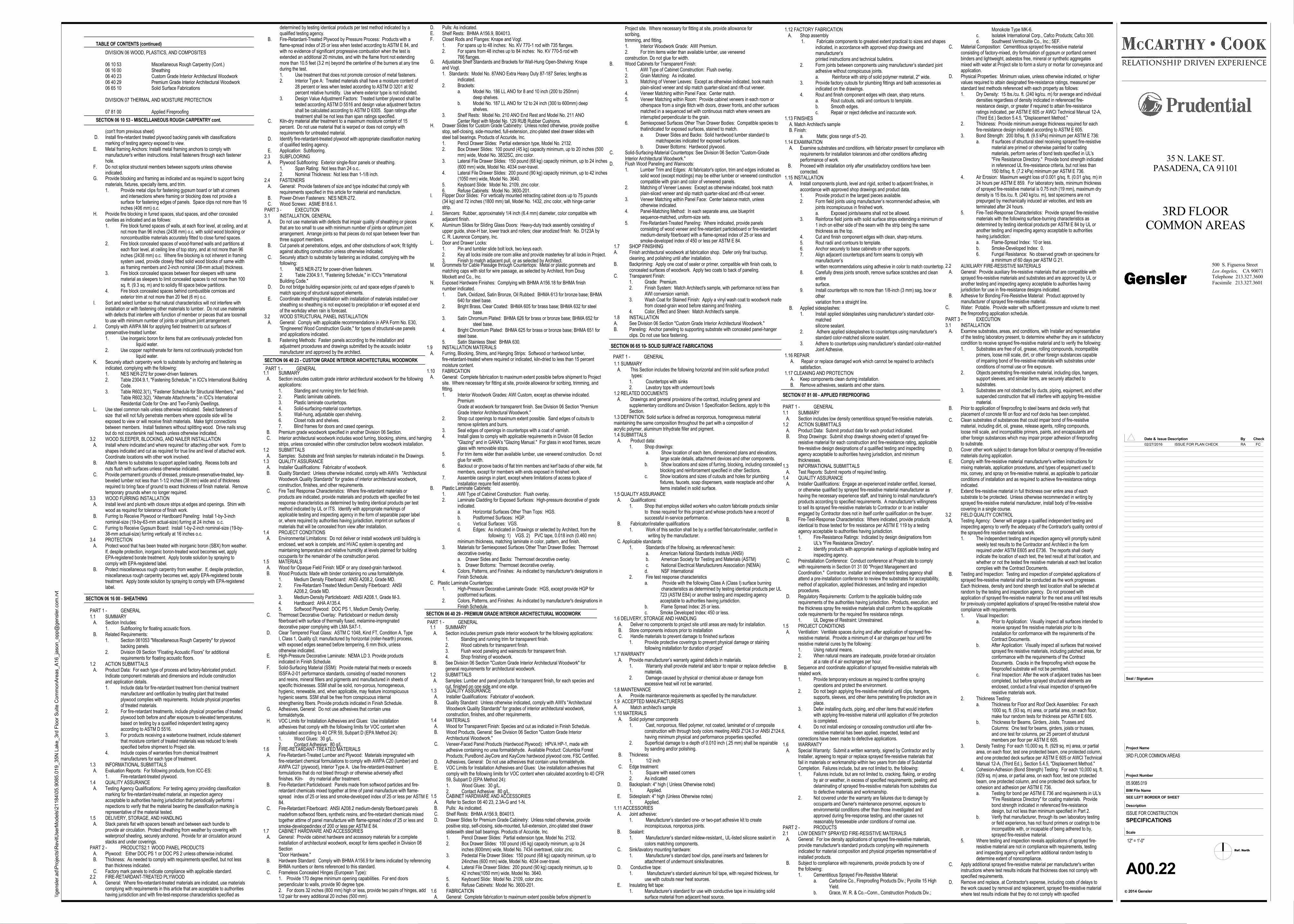
1.1 SUMMARY A. Section includes custom grade interior architectural woodwork for the following
applications:1. Standing and running trim for field finish.2. Plastic laminate cabinets.3. Plastic laminate countertops.4. Solid-surfacing-material countertops.5. Wall-hung, adjustable open shelving.6. Closet rods and shelves.7. Blind frames for doors and cased openings.
B. Premium grade woodwork specified in another Division 06 Section. C. Interior architectural woodwork includes wood furring, blocking, shims, and hanging
strips, unless concealed within other construction before woodwork installation.1.2 SUBMITTALS A. Samples: Substrate and finish samples for materials indicated in the Drawings.1.3 QUALITY ASSURANCE A. Installer Qualifications: Fabricator of woodwork. B. Quality Standard: Unless otherwise indicated, comply with AWI's "Architectural
Woodwork Quality Standards" for grades of interior architectural woodwork,construction, finishes, and other requirements.
C. Fire Test Response Characteristics: Where fire-retardant materials orproducts are indicated, provide materials and products with specified fire testresponse characteristics as determined by testing identical products per testmethod indicated by UL or ITS. Identify with appropriate markings ofapplicable testing and inspecting agency in the form of separable paper labelor, where required by authorities having jurisdiction, imprint on surfaces ofmaterials that will be concealed from view after installation.
1.4 PROJECT CONDITIONS A. Environmental Limitations: Do not deliver or install woodwork until building is
enclosed, wet work is complete, and HVAC system is operating andmaintaining temperature and relative humidity at levels planned for buildingoccupants for the remainder of the construction period.
1.5 MATERIALS A. Wood for Opaque Field Finish: MDF or any closed-grain hardwood. B. Wood Products: Made with binder containing no urea formaldehyde.
1. Medium Density Fiberboard: ANSI A208.2, Grade MD.2. Fire-Retardant-Treated Medium Density Fiberboard: ANSI
A208.2, Grade MD.3. Medium-Density Particleboard: ANSI A208.1, Grade M-3.4. Hardboard: AHA A135.4.5. Softwood Plywood: DOC PS 1, Medium Density Overlay.
C. Thermoset Decorative Overlay: Particleboard or medium density fiberboard with surface of thermally fused, melamine-impregnateddecorative paper complying with LMA SAT-1.
D. Clear Tempered Float Glass: ASTM C 1048, Kind FT, Condition A, TypeI, Class 1, Quality q3; manufactured by horizontal (roller-hearth) process,with exposed edges seamed before tempering, 6 mm thick, unlessotherwise indicated.
E. High-Pressure Decorative Laminate: NEMA LD 3. Provide productsindicated in Finish Schedule.
F. Solid-Surfacing Material (SSM): Provide material that meets or exceedsISSFA-2-01 performance standards, consisting of reacted monomersand resins, mineral fillers and pigments and manufactured in sheets ofspecific thicknesses. SSM shall be solid, non-porous, homogeneous,hygienic, renewable, and, when applicable, may feature inconspicuoushygienic seams. SSM shall be free from conspicuous internalstrengthening fibers. Provide products indicated in Finish Schedule.
G. Adhesives, General: Do not use adhesives that contain ureaformaldehyde.
H. VOC Limits for Installation Adhesives and Glues: Use installationadhesives that comply with the following limits for VOC content whencalculated according to 40 CFR 59, Subpart D (EPA Method 24):1. Wood Glues: 30 g/L.2. Contact Adhesive: 80 g/L.
1.6 FIRE-RETARDANT-TREATED MATERIALS A. Fire-Retardant-Treated Lumber and Plywood: Materials impregnated with
fire-retardant chemical formulations to comply with AWPA C20 (lumber) andAWPA C27 (plywood), Interior Type A. Use fire-retardant-treatmentformulations that do not bleed through or otherwise adversely affectfinishes. Kiln- dry material after treatment.
B. Fire-Retardant Particleboard: Panels made from softwood particles and fire-retardant chemicals mixed together at time of panel manufacture with flame-spread index of 25 or less and smoke-developed index of 25 or less per ASTM E84.
C. Fire-Retardant Fiberboard: ANSI A208.2 medium-density fiberboard panelsmadefrom softwood fibers, synthetic resins, and fire-retardant chemicals mixedtogether attime of panel manufacture with flame-spread index of 25 or less andsmoke-developedindex of 200 or less per ASTM E 84.
1.7 CABINET HARDWARE AND ACCESSORIES A. General: Provide cabinet hardware and accessory materials for a complete
installation of architectural woodwork, except for items specified in Division 08Section"Door Hardware."
B. Hardware Standard: Comply with BHMA A156.9 for items indicated by referencingBHMA numbers or items referenced to this standard.
C. Frameless Concealed Hinges (European Type):1. Provide 170 degree minimum opening capabilities. For end doorsperpendicular to walls, provide 90 degree type.2. For doors 32 inches (800 mm) high or less, provide two pairs of hinges, add1/2 pair for every additional 20 inches (500 mm).
G. Adjustable Shelf Standards and Brackets for Wall-Hung Open-Shelving: Knapeand Vogt.1. Standards: Model No. 87ANO Extra Heavy Duty 87-187 Series; lengths as
indicated.2. Brackets:
a. Model No. 186 LL ANO for 8 and 10 inch (200 to 250mm) deep shelves.
b. Model No. 187 LL ANO for 12 to 24 inch (300 to 600mm) deep shelves.
3. Shelf Rests: Model No. 210 ANO End Rest and Model No. 211 ANO Center Rest with Model No. 129 RUB Rubber Cushions.
H. Drawer Slides for Custom Grade Cabinetry: Unless noted otherwise, provide positivestop, self-closing, side-mounted, full-extension, zinc-plated steel drawer slides withsteel ball bearings. Products of Accuride, Inc.1. Pencil Drawer Slides: Partial extension type, Model No. 2132.2. Box Drawer Slides: 100 pound (45 kg) capacity minimum, up to 20 inches (500
mm) wide, Model No. 3832SC, zinc color.3. Lateral File Drawer Slides: 150 pound (68 kg) capacity minimum, up to 24 inches
(600 mm) wide, Model No. 4034 over-travel.4. Lateral File Drawer Slides: 200 pound (90 kg) capacity minimum, up to 42 inches
(1050 mm) wide, Model No. 3640.5. Keyboard Slide: Model No. 2109, zinc color.6. Refuse Cabinets: Model No. 3600-201.
I. Flipper Door Slides: For vertically mounted retracting cabinet doors up to 75 pounds(34 kg) and 72 inches (1800 mm) tall, Model No. 1432, zinc color, with hinge carrierstrip.
J. Silencers: Rubber, approximately 1/4 inch (6.4 mm) diameter, color compatible withadjacent finish.
K. Aluminum Slides for Sliding Glass Doors: Heavy-duty track assembly consisting ofupper guide, shoe-H bar, lower track and rollers; clear anodized finish: No. D123A byC. R. Laurence Company, Inc.
L. Door and Drawer Locks:1. Pin and tumbler slide bolt lock, two keys each.2. Key all locks inside one room alike and provide masterkey for all locks in Project.3. Finish to match adjacent pull, or as selected by Architect.
M. Grommets for Cable Passage through Countertops: Metal or plastic grommets andmatching caps with slot for wire passage, as selected by Architect, from DougMockett and Co., Inc.
N. Exposed Hardware Finishes: Complying with BHMA A156.18 for BHMA finishnumber indicated.1. Dark, Oxidized, Satin Bronze, Oil Rubbed: BHMA 613 for bronze base; BHMA
640 for steel base.2. Bright Brass, Clear Coated: BHMA 605 for brass base; BHMA 632 for steel
base.3. Satin Chromium Plated: BHMA 626 for brass or bronze base; BHMA 652 for
steel base.4. Bright Chromium Plated: BHMA 625 for brass or bronze base; BHMA 651 for
steel base.5. Satin Stainless Steel: BHMA 630.
1.9 INSTALLATION MATERIALS A. Furring, Blocking, Shims, and Hanging Strips: Softwood or hardwood lumber,
fire-retardant-treated where required or indicated, kiln-dried to less than 15 percentmoisture content.
1.10 FABRICATION A. General: Complete fabrication to maximum extent possible before shipment to Project
site. Where necessary for fitting at site, provide allowance for scribing, trimming, andfitting.1. Interior Woodwork Grades: AWI Custom, except as otherwise indicated.
PremiumGrade at woodwork for transparent finish. See Division 06 Section "PremiumGrade Interior Architectural Woodwork."
2. Shop cut openings to maximum extent possible. Sand edges of cutouts toremove splinters and burrs.
3. Seal edges of openings in countertops with a coat of varnish.4. Install glass to comply with applicable requirements in Division 08 Section
"Glazing" and in GANA's "Glazing Manual." For glass in wood frames, secureglass with removable stops.
5. For trim items wider than available lumber, use veneered construction. Do notglue for width.
6. Backout or groove backs of flat trim members and kerf backs of other wide, flatmembers, except for members with ends exposed in finished work.
7. Assemble casings in plant, except where limitations of access to place ofinstallation require field assembly.
B. Plastic Laminate Cabinets:1. AWI Type of Cabinet Construction: Flush overlay.2. Laminate Cladding for Exposed Surfaces: High-pressure decorative of grade
indicated.a. Horizontal Surfaces Other Than Tops: HGS.b. Postformed Surfaces: HGP.c. Vertical Surfaces: VGS.d. Edges: As indicated in Drawings or selected by Architect, from the
following: 1) VGS. 2) PVC tape, 0.018 inch (0.460 mm)minimum thickness, matching laminate in color, pattern, and finish.
3. Materials for Semiexposed Surfaces Other Than Drawer Bodies: Thermosetdecorative overlay.a. Drawer Sides and Backs: Thermoset decorative overlay.b. Drawer Bottoms: Thermoset decorative overlay.
4. Colors, Patterns, and Finishes: As indicated by manufacturer's designations inFinish Schedule.
C. Plastic Laminate Countertops:1. High-Pressure Decorative Laminate Grade: HGS, except provide HGP for
postformed surfaces.2. Colors, Patterns, and Finishes: As indicated by manufacturer's designations in
Finish Schedule.PART 1 - GENERAL1.1 SUMMARY A. Section Includes:
1. Subflooring for floating acoustic floors. B. Related Requirements:
1. Section 061053 "Miscellaneous Rough Carpentry" for plywood backing panels.
2. Division 09 Section “Floating Acoustic Floors” for additional requirements for floating acoustic floors.
1.2 ACTION SUBMITTALS A. Product Data: For each type of process and factory-fabricated product.
Indicate component materials and dimensions and include constructionand application details.1. Include data for fire-retardant treatment from chemical treatment
manufacturer and certification by treating plant that treated plywood complies with requirements. Include physical propertiesof treated materials.
2. For fire-retardant treatments, include physical properties of treatedplywood both before and after exposure to elevated temperatures,based on testing by a qualified independent testing agency according to ASTM D 5516.
3. For products receiving a waterborne treatment, include statement that moisture content of treated materials was reduced to levels specified before shipment to Project site.
4. Include copies of warranties from chemical treatment manufacturers for each type of treatment.
1.3 INFORMATIONAL SUBMITTALS A. Evaluation Reports: For following products, from ICC-ES:
1. Fire-retardant-treated plywood.1.4 QUALITY ASSURANCE A. Testing Agency Qualifications: For testing agency providing classification
marking for fire-retardant-treated material, an inspection agencyacceptable to authorities having jurisdiction that periodically performs inspections to verify that the material bearing the classification marking isrepresentative of the material tested.
1.5 DELIVERY, STORAGE, AND HANDLING A. Stack panels flat with spacers beneath and between each bundle to
provide air circulation. Protect sheathing from weather by covering withwaterproof sheeting, securely anchored. Provide for air circulation aroundstacks and under coverings.
PART 2 - PRODUCTS2.1 WOOD PANEL PRODUCTS A. Plywood: Either DOC PS 1 or DOC PS 2 unless otherwise indicated. B. Thickness: As needed to comply with requirements specified, but not less
than thickness indicated. C. Factory mark panels to indicate compliance with applicable standard.2.2 FIRE-RETARDANT-TREATED PLYWOOD A. General: Where fire-retardant-treated materials are indicated, use materials
complying with requirements in this article that are acceptable to authoritieshaving jurisdiction and with fire-test-response characteristics specified as
G. Provide blocking and framing as indicated and as required to support facingmaterials, fixtures, specialty items, and trim.1. Provide metal clips for fastening gypsum board or lath at corners
and intersections where framing or blocking does not provide a surface for fastening edges of panels. Space clips not more than 16inches (406 mm) o.c.
H. Provide fire blocking in furred spaces, stud spaces, and other concealedcavities as indicated and as follows:1. Fire block furred spaces of walls, at each floor level, at ceiling, and at
not more than 96 inches (2438 mm) o.c. with solid wood blocking ornoncombustible materials accurately fitted to close furred spaces.
2. Fire block concealed spaces of wood-framed walls and partitions ateach floor level, at ceiling line of top story, and at not more than 96inches (2438 mm) o.c. Where fire blocking is not inherent in framingsystem used, provide closely fitted solid wood blocks of same widthas framing members and 2-inch nominal (38-mm actual) thickness.
3. Fire block concealed spaces between floor sleepers with same material as sleepers to limit concealed spaces to not more than 100sq. ft. (9.3 sq. m) and to solidly fill space below partitions.
4. Fire block concealed spaces behind combustible cornices and exterior trim at not more than 20 feet (6 m) o.c.
I. Sort and select lumber so that natural characteristics will not interfere withinstallation or with fastening other materials to lumber. Do not use materialswith defects that interfere with function of member or pieces that are toosmallto use with minimum number of joints or optimum joint arrangement.
J. Comply with AWPA M4 for applying field treatment to cut surfaces ofpreservative-treated lumber.1. Use inorganic boron for items that are continuously protected from
liquid water.2. Use copper naphthenate for items not continuously protected from
liquid water. K. Securely attach carpentry work to substrate by anchoring and fastening as
indicated, complying with the following:1. NES NER-272 for power-driven fasteners.2. Table 2304.9.1, "Fastening Schedule," in ICC's International Building
Code.3. Table R602.3(1), "Fastener Schedule for Structural Members," and
Table R602.3(2), "Alternate Attachments," in ICC's International Residential Code for One- and Two-Family Dwellings.
L. Use steel common nails unless otherwise indicated. Select fasteners ofsize that will not fully penetrate members where opposite side will beexposed to view or will receive finish materials. Make tight connectionsbetween members. Install fasteners without splitting wood. Drive nails snugbut do not countersink nail heads unless otherwise indicated.
3.2 WOOD SLEEPER, BLOCKING, AND NAILER INSTALLATION A. Install where indicated and where required for attaching other work. Form to
shapes indicated and cut as required for true line and level of attached work.Coordinate locations with other work involved.
B. Attach items to substrates to support applied loading. Recess bolts andnuts flush with surfaces unless otherwise indicated.
C. Provide permanent grounds of dressed, pressure-preservative-treated, key-beveled lumber not less than 1-1/2 inches (38 mm) wide and of thicknessrequired to bring face of ground to exact thickness of finish material. Removetemporary grounds when no longer required.
3.3 WOOD FURRING INSTALLATION A. Install level and plumb with closure strips at edges and openings. Shim with
wood as required for tolerance of finish work. B. Furring to Receive Plywood or Hardboard Paneling: Install 1-by-3-inch
nominal-size (19-by-63-mm actual-size) furring at 24 inches o.c. C. Furring to Receive Gypsum Board: Install 1-by-2-inch nominal-size (19-by-
38-mm actual-size) furring vertically at 16 inches o.c.3.4 PROTECTION A. Protect wood that has been treated with inorganic boron (SBX) from weather.
If, despite protection, inorganic boron-treated wood becomes wet, applyEPA-registered borate treatment. Apply borate solution by spraying tocomply with EPA-registered label.
B. Protect miscellaneous rough carpentry from weather. If, despite protection,miscellaneous rough carpentry becomes wet, apply EPA-registered boratetreatment. Apply borate solution by spraying to comply with EPA-registeredlabel.
TABLE OF CONTENTS (continued)
DIVISION 06 WOOD, PLASTICS, AND COMPOSITES
06 10 53 Miscellaneous Rough Carpentry (Cont.)06 16 00 Sheathing06 40 23 Custom Grade Interior Architectural Woodwork
06 40 29 Premium Grade Interior Architectural Woodwork06 65 10 Solid Surface Fabrications
DIVISION 07 THERMAL AND MOISTURE PROTECTION
07 81 00 Applied Fireproofing
C. Kiln-dry material after treatment to a maximum moisture content of 15percent. Do not use material that is warped or does not comply withrequirements for untreated material.
D. Identify fire-retardant-treated plywood with appropriate classification markingof qualified testing agency.
E. Application: Subflooring.2.3 SUBFLOORING A. Plywood Subflooring: Exterior single-floor panels or sheathing.
1. Span Rating: Not less than 24 o.c..2. Nominal Thickness: Not less than 1-1/8 inch.
2.4 FASTENERS A. General: Provide fasteners of size and type indicated that comply with
requirements specified in this article for material and manufacture. B. Power-Driven Fasteners: NES NER-272. C. Wood Screws: ASME B18.6.1.PART 3 - EXECUTION3.1 INSTALLATION, GENERAL A. Do not use materials with defects that impair quality of sheathing or pieces
that are too small to use with minimum number of joints or optimum jointarrangement. Arrange joints so that pieces do not span between fewer thanthree support members.
B. Cut panels at penetrations, edges, and other obstructions of work; fit tightlyagainst abutting construction unless otherwise indicated.
C. Securely attach to substrate by fastening as indicated, complying with thefollowing:1. NES NER-272 for power-driven fasteners.2. Table 2304.9.1, "Fastening Schedule," in ICC's "InternationalBuilding Code."
D. Do not bridge building expansion joints; cut and space edges of panels tomatch spacing of structural support elements.
E. Coordinate sheathing installation with installation of materials installed oversheathing so sheathing is not exposed to precipitation or left exposed at endof the workday when rain is forecast.
3.2 WOOD STRUCTURAL PANEL INSTALLATION A. General: Comply with applicable recommendations in APA Form No. E30,
"Engineered Wood Construction Guide," for types of structural-use panelsand applications indicated.
B. Fastening Methods: Fasten panels according to the installation andadjustment procedures and drawings submitted by the acoustic isolatormanufacturer and approved by the architect.
1.1 SUMMARY A. Section includes premium grade interior woodwork for the following applications:
1. Standing and running trim for transparent finish.2. Wood cabinets for transparent finish.3. Flush wood paneling and wainscots for transparent finish.4. Shop finishing of woodwork.
B. See Division 06 Section "Custom Grade Interior Architectural Woodwork" forgeneral requirements for architectural woodwork.
1.2 SUBMITTALS A. Samples: Lumber and panel products for transparent finish, for each species and
cut, finished on one side and one edge.1.3 QUALITY ASSURANCE A. Installer Qualifications: Fabricator of woodwork. B. Quality Standard: Unless otherwise indicated, comply with AWI's "Architectural
Woodwork Quality Standards" for grades of interior architectural woodwork,construction, finishes, and other requirements.
1.4 MATERIALS A. Wood for Transparent Finish: Species and cut as indicated in Finish Schedule. B. Wood Products, General: See Division 06 Section "Custom Grade Interior
Architectural Woodwork." C. Veneer-Faced Panel Products (Hardwood Plywood): HPVA HP-1, made with
adhesive containing no urea formaldehyde. Available Product: Columbia ForestProducts; PureBond JayCore and KayCore hardwood plywood core, FSC Certified.
D. Adhesives, General: Do not use adhesives that contain urea formaldehyde. E. VOC Limits for Installation Adhesives and Glues: Use installation adhesives that
comply with the following limits for VOC content when calculated according to 40 CFR59, Subpart D (EPA Method 24):1. Wood Glues: 30 g/L.2. Contact Adhesive: 80 g/L.
1.5 CABINET HARDWARE AND ACCESSORIES A. Refer to Section 06 40 23, 2.3A-G and 1-N. B. Pulls: As indicated. C. Shelf Rests: BHMA A156.9, B04013. D. Drawer Slides for Premium Grade Cabinetry: Unless noted otherwise, provide
positive stop, self-closing, side-mounted, full-extension, zinc-plated steel drawerslideswith steel ball bearings. Products of Accuride, Inc.1. Pencil Drawer Slides: Partial extension type, Model No. 2132.2. Box Drawer Slides: 100 pound (45 kg) capacity minimum, up to 24
inches (600mm) wide, Model No. 7434 overtravel, color zinc.3. Pedestal File Drawer Slides: 150 pound (68 kg) capacity minimum, up to
24inches (600 mm) wide, Model No. 4034 over-travel.4. Lateral File Drawer Slides: 200 pound (90 kg) capacity minimum, up to
42 inches(1050 mm) wide, Model No. 3640.5. Keyboard Slide: Model No. 2109, color zinc.6. Refuse Cabinets: Model No. 3600-201.
1.6 FABRICATION A. General: Complete fabrication to maximum extent possible before shipment to
B. Wood Cabinets for Transparent Finish:1. AWI Type of Cabinet Construction: Flush overlay.2. Grain Matching: As indicated.3. Matching of Veneer Leaves: Except as otherwise indicated, book match
plain-sliced veneer and slip match quarter-sliced and rift-cut veneer.4. Veneer Matching within Panel Face: Center match.5. Veneer Matching within Room: Provide cabinet veneers in each room or
otherspace from a single flitch with doors, drawer fronts, and other surfaces matched in a sequenced set with continuous match where veneers are interrupted perpendicular to the grain.
6. Semiexposed Surfaces Other Than Drawer Bodies: Compatible species to thatindicated for exposed surfaces, stained to match.a. Drawer Sides and Backs: Solid hardwood lumber standard to
matchspecies indicated for exposed surfaces.b. Drawer Bottoms: Hardwood plywood.
C. Solid-Surfacing-Material Countertops: See Division 06 Section "Custom-GradeInterior Architectural Woodwork."
D. Flush Wood Paneling and Wainscots:1. Lumber Trim and Edges: At fabricator's option, trim and edges indicated as
solid wood (except moldings) may be either lumber or veneered constructioncompatible with grain and color of veneered panels.
2. Matching of Veneer Leaves: Except as otherwise indicated, book matchplain-sliced veneer and slip match quarter-sliced and rift-cut veneer.
3. Veneer Matching within Panel Face: Center balance match, unless otherwise indicated.
4. Panel-Matching Method: In each separate area, use blueprintsequence-matched, uniform-size sets.
5. Fire-Retardant-Treated Paneling: Where indicated, provide panels consisting of wood veneer and fire-retardant particleboard or fire-retardant medium-density fiberboard with a flame-spread index of 25 or less and smoke-developed index of 450 or less per ASTM E 84.
1.7 SHOP FINISHINGA. Finish architectural woodwork at fabrication shop. Defer only final touchup,
cleaning, and polishing until after installation.B. Backpriming: Apply one coat of sealer or primer, compatible with finish coats, to
concealed surfaces of woodwork. Apply two coats to back of paneling.C. Transparent Finish:
1. Grade: Premium.2. Finish System: Match Architect's sample, with performance not less than
AWI conversion varnish.3. Wash Coat for Stained Finish: Apply a vinyl wash coat to woodwork made
from closed-grain wood before staining and finishing.4. Color, Effect and Sheen: Match Architect's sample.
1.8 INSTALLATIONA. See Division 06 Section "Custom Grade Interior Architectural Woodwork."B. Paneling: Anchor paneling to supporting substrate with concealed panel-hanger
clips. Do not use face fastening.
1.1 SUMMARY A. This Section includes the following horizontal and trim solid surface product types: 1. Countertops with sinks
2. Lavatory tops with undermount bowls1.2 RELATED DOCUMENTS A. Drawings and general provisions of the contract, including general and
supplementary conditions and Division 1 Specification Sections, apply to thisSection.
1.3 DEFINITION: Solid surface is defined as nonporous, homogeneous materialmaintaining the same composition throughout the part with a composition ofacrylic polymer, aluminum trihydrate filler and pigment.1.4 SUBMITTALS A. Product data:
1. Shop drawings: a. Show location of each item, dimensioned plans and elevations,
large scale details, attachment devices and other components. b. Show locations and sizes of furring, blocking, including concealed
blocking and reinforcement specified in other Sections. c. Show locations and sizes of cutouts and holes for plumbing
fixtures, faucets, soap dispensers, waste receptacle and other items installed in solid surface.
1.5 QUALITY ASSURANCE A. Qualifications:
1. Shop that employs skilled workers who custom fabricate products similar to those required for this project and whose products have a record of
successful in-service performance. B. Fabricator/installer qualifications
1. Work of this section shall be by a certified fabricator/installer, certified in writing by the manufacturer. C. Applicable standards:
1. Standards of the following, as referenced herein: a. American National Standards Institute (ANSI) b. American Society for Testing and Materials (ASTM) c. National Electrical Manufacturers Association (NEMA) d. NSF International
2. Fire test response characteristics a. Provide with the following Class A (Class I) surface burning characteristics as determined by testing identical products per UL
723 (ASTM E84) or another testing and inspecting agency acceptable to authorities having jurisdiction.
b. Flame Spread Index: 25 or less. c. Smoke Developed Index: 450 or less.1.6 DELIVERY, STORAGE AND HANDLING A. Deliver no components to project site until areas are ready for installation. B. Store components indoors prior to installation C. Handle materials to prevent damage to finished surfaces
1. Provide protective coverings to prevent physical damage or staining following installation for duration of project'
1.7 WARRANTY A. Provide manufacturer’s warranty against defects in materials.
1. Warranty shall provide material and labor to repair or replace defective materials.
2. Damage caused by physical or chemical abuse or damage from excessive heat will not be warranted.
1.8 MAINTENANCE A. Provide maintenance requirements as specified by the manufacturer.1.9 ACCEPTED MANUFACTURERSA. Match architect's sample1.10 MATERIALS A. Solid polymer components
1. Cast, nonporous, filled polymer, not coated, laminated or of composite construction with through body colors meeting ANSI Z124.3 or ANSI Z124.6, having minimum physical and performance properties specified.
2. Superficial damage to a depth of 0.010 inch (.25 mm) shall be repairable by sanding and/or polishing.
B. Thickness:1. 1/2 inch
C. Edge treatment:1. Square with eased corners2. As indicated
D. Backsplash: 4" high ( Unless Otherwise noted)1. Applied.
E. Sidesplash: 4" high (Unless Otherwise notes)1. Applied.
1.11 ACCESSORIES A. Joint adhesive:
1. Manufacturer’s standard one- or two-part adhesive kit to createinconspicuous, nonporous joints.
B. Sealant:1. Manufacturer’s standard mildew-resistant,, UL-listed silicone sealant in
colors matching components. C. Sink/lavatory mounting hardware:
1. Manufacturer’s standard bowl clips, panel inserts and fasteners forattachment of undermount sinks/lavatories.
D. Conductive tape:1. Manufacturer’s standard aluminum foil tape, with required thickness, for
use with cutouts near heat sources. E. Insulating felt tape:
1. Manufacturer’s standard for use with conductive tape in insulating solidsurface material from adjacent heat source.
1.12 FACTORY FABRICATION A. Shop assembly
1. Fabricate components to greatest extent practical to sizes and shapes indicated, in accordance with approved shop drawings and
manufacturer’s printed instructions and technical bulletins.
2. Form joints between components using manufacturer’s standard joint adhesive without conspicuous joints. a. Reinforce with strip of solid polymer material, 2" wide.
3. Provide factory cutouts for plumbing fittings and bath accessories as indicated on the drawings.
4. Rout and finish component edges with clean, sharp returns. a. Rout cutouts, radii and contours to template. b. Smooth edges. c. Repair or reject defective and inaccurate work.1.13 FINISHES A. Match Architect's sample B. Finish:
a. Matte; gloss range of 5–20.1.14 EXAMINATION A. Examine substrates and conditions, with fabricator present for compliance with
requirements for installation tolerances and other conditions affectingperformance of work.
B. Proceed with installation only after unsatisfactory conditions have beencorrected.
1.15 INSTALLATION A. Install components plumb, level and rigid, scribed to adjacent finishes, in
accordance with approved shop drawings and product data.1. Provide product in the largest pieces available.2. Form field joints using manufacturer’s recommended adhesive, with
joints inconspicuous in finished work. a. Exposed joints/seams shall not be allowed.
3. Reinforce field joints with solid surface strips extending a minimum of1 inch on either side of the seam with the strip being the same thickness as the top.
4. Cut and finish component edges with clean, sharp returns.5. Rout radii and contours to template.6. Anchor securely to base cabinets or other supports.7. Align adjacent countertops and form seams to comply with
manufacturer’s written recommendations using adhesive in color to match countertop.
8. Carefully dress joints smooth, remove surface scratches and cleanentire
surface.9. Install countertops with no more than 1/8-inch (3 mm) sag, bow or
othervariation from a straight line.
B. Applied sidesplashes:1. Install applied sidesplashes using manufacturer’s standard color-
matched silicone sealant.
2. Adhere applied sidesplashes to countertops using manufacturer’sstandard color-matched silicone sealant.
3. Adhere to countertops using manufacturer’s standard color-matchedJoint Adhesive.
1.16 REPAIR A. Repair or replace damaged work which cannot be repaired to architect’s
satisfaction.1.17 CLEANING AND PROTECTION A. Keep components clean during installation. B. Remove adhesives, sealants and other stains.
SECTION 07 81 00 - APPLIED FIREPROOFING
PART 1 - GENERAL1.1 SUMMARY A. Section includes low density cementitious sprayed fire-resistive materials.1.2 ACTION SUBMITTALS A. Product Data: Submit product data for each product indicated. B. Shop Drawings: Submit shop drawings showing extent of sprayed fire-
resistive material for each construction and fire-resistance rating, applicablefire-resistive design designations of a qualified testing and inspectingagency acceptable to authorities having jurisdiction, and minimumthicknesses.
1.3 INFORMATIONAL SUBMITTALS A. Test Reports: Submit reports of required testing.1.4 QUALITY ASSURANCE A. Installer Qualifications: Engage an experienced installer certified, licensed,
or otherwise qualified by sprayed fire-resistive material manufacturer ashaving the necessary experience staff, and training to install manufacturer'sproducts according to specified requirements. A manufacturer's willingnessto sell its sprayed fire-resistive materials to Contractor or to an installerengaged by Contractor does not in itself confer qualification on the buyer.
B. Fire-Test-Response Characteristics: Where indicated, provide productsidentical to those tested for fire resistance per ASTM E 119 by a testingagency acceptable to authorities having jurisdiction.1. Fire-Resistance Ratings: Indicated by design designations from
UL's "Fire Resistance Directory".2. Identify products with appropriate markings of applicable testing and
inspecting agency. C. Preinstallation Conference: Conduct conference at Project site to comply
with requirements in Section 01 31 00 "Project Management andCoordination." Contractor, installer and independent testing agency shallattend a pre-installation conference to review the substrates for acceptability,method of application, applied thicknesses, and testing and inspectionprocedures.
D. Regulatory Requirements: Conform to the applicable building coderequirements of the authorities having jurisdiction. Products, execution, andthe thickness spray fire resistive materials shall conform to the applicablecode requirements for the required fire resistance ratings.1. UL Degree of Restraint: Unrestrained.
1.5 PROJECT CONDITIONS A. Ventilation: Ventilate spaces during and after application of sprayed fire-
resistive material. Provide a minimum of 4 air changes per hour until fireresistive material cures by the following:1. Using natural means.2. When natural means are inadequate, provide forced-air circulation
at a rate of 4 air exchanges per hour. B. Sequence and coordinate application of sprayed fire-resistive materials with
related work.1. Provide temporary enclosure as required to confine spraying
operations and protect the environment.2. Do not begin applying fire-resistive material until clips, hangers,
supports, sleeves, and other items penetrating fire protection are inplace.
3. Defer installing ducts, piping, and other items that would interfere with applying fire-resistive material until application of fire protectionis completed.
4. Do not install enclosing or concealing construction until after fire-resistive material has been applied, inspected, tested and
corrections have been made to defective applications.1.6 WARRANTY A. Special Warranty: Submit a written warranty, signed by Contractor and by
Installer, agreeing to repair or replace sprayed fire-resistive materials thatfail in materials or workmanship within two years from date of SubstantialCompletion. Failures include, but are not limited to, the following:1. Failures include, but are not limited to, cracking, flaking, or eroding
by air or weather, in excess of specified requirements; peeling; anddelaminating of sprayed fire-resistive materials from substrates dueto defective materials and workmanship.
2. Not covered under the warranty are failures due to damage by occupants and Owner's maintenance personnel, exposure to environmental conditions other than those investigated and approved during fire-response testing, and other causes not reasonably foreseeable under conditions of normal use.
PART 2 - PRODUCTS2.1 LOW DENSITY SPRAYED FIRE-RESISTIVE MATERIALS A. General: For low density applications of sprayed fire-resistive materials,
provide manufacturer's standard products complying with requirementsindicated for material composition and physical properties representative ofinstalled products.
B. Subject to compliance with requirements, provide products by one of the following:1. Cementitious Sprayed Fire-Resistive Material:
a. Carboline Co., Fireproofing Products Div.; Pyrolite 15 HighYield.
b. Grace, W. R. & Co.--Conn., Construction Products Div.;
C. Material Composition: Cementitious sprayed fire-resistive materialconsisting of factory-mixed, dry formulation of gypsum or portland cementbinders and lightweight, asbestos free, mineral or synthetic aggregatesmixed with water at Project site to form a slurry or mortar for conveyance andapplication.
D. Physical Properties: Minimum values, unless otherwise indicated, or highervalues required to attain designated fire-resistance ratings, measured perstandard test methods referenced with each property as follows:1. Dry Density: 15 lbs./cu. ft. (240 kg/cu. m) for average and individual
densities regardless of density indicated in referenced fire-resistance design, or greater if required to attain fire-resistance ratings indicated, per ASTM E 605 or AWCI Technical Manual 12-A,(Third Ed.) Section 5.4.5, "Displacement Method."
2. Thickness: Provide minimum average thickness required for eachfire-resistance design indicated according to ASTM E 605.
3. Bond Strength: 200 lbf/sq. ft. (9.5 kPa) minimum per ASTM E 736:a. If surfaces of structural steel receiving sprayed fire-resistive
material are primed or otherwise painted for coating materials, perform series of bond tests specified in UL's "Fire Resistance Directory." Provide bond strength indicatedin referenced UL fire-resistance criteria, but not less than 150 lbf/sq. ft. (7.2 kPa) minimum per ASTM E 736.
4. Air Erosion: Maximum weight loss of 0.001 g/sq. ft. (0.01 g/sq. m) in24 hours per ASTM E 859. For laboratory tests, minimum thicknessof sprayed fire-resistive material is 0.75 inch (19 mm), maximum drydensity is 15 lbs./cu. ft. (240 kg/cu. m), test specimens are not prepurged by mechanically induced air velocities, and tests are terminated after 24 hours.
5. Fire-Test-Response Characteristics: Provide sprayed fire-resistivematerials with the following surface-burning characteristics as determined by testing identical products per ASTM E 84 by UL or another testing and inspecting agency acceptable to authorities having jurisdiction:a. Flame-Spread Index: 10 or less.b. Smoke-Developed Index: 0.6. Fungal Resistance: No observed growth on specimens for
a minimum of 60 days per ASTM G 21.2.2 AUXILIARY FIRE-RESISTIVE MATERIALS A. General: Provide auxiliary fire-resistive materials that are compatible with
sprayed fire-resistive materials and substrates and are approved by UL oranother testing and inspecting agency acceptable to authorities havingjurisdiction for use in fire-resistance designs indicated.
B. Adhesive for Bonding Fire-Resistive Material: Product approved bymanufacturer of sprayed fire-resistive material.
C. Water: Potable. Provide water with sufficient pressure and volume to meetthe fireproofing application schedule.
PART 3 - EXECUTION3.1 INSTALLATION A. Examine substrates, areas, and conditions, with Installer and representative
of the testing laboratory present, to determine whether they are in satisfactorycondition to receive sprayed fire-resistive material and to verify the following:1. Substrates are free of oil, grease, rolling compounds, incompatible
primers, loose mill scale, dirt, or other foreign substances capableof impairing bond of fire-resistive materials with substrates under conditions of normal use or fire exposure.
2. Objects penetrating fire-resistive material, including clips, hangers,support sleeves, and similar items, are securely attached to substrates.
3. Substrates are not obstructed by ducts, piping, equipment, and othersuspended construction that will interfere with applying fire-resistivematerial.
B. Prior to application of fireproofing to steel beams and decks verify thatplacement of concrete fill on floor and roof decks has been completed.
C. Clean substrates of substances that could impair bond of fire-resistivematerial, including dirt, oil, grease, release agents, rolling compounds,loose mill scale, and incompatible primers, paints, and encapsulants andother foreign substances which may impair proper adhesion of fireproofingto substrate.
D. Cover other work subject to damage from fallout or overspray of fire-resistivematerials during application.
E. Comply with fire-resistive material manufacturer's written instructions formixing materials, application procedures, and types of equipment used tomix, convey, and spray on fire-resistive material, as applicable to particularconditions of installation and as required to achieve fire-resistance ratingsindicated.
F. Extend fire-resistive material in full thickness over entire area of eachsubstrate to be protected. Unless otherwise recommended in writing bysprayed fire-resistive material manufacturer, install body of fire-resistivecovering in a single course.
3.2 FIELD QUALITY CONTROL A. Testing Agency: Owner will engage a qualified independent testing and
inspecting agency to verify the adequacy of the Contractor's quality control ofthe sprayed-fire resistive materials work.1. The independent testing and inspection agency will promptly submit
weekly test results to the Contractor and Architect in the form required under ASTM E605 and E736. The reports shall clearly indicate the location of each test, the test result at that location, andwhether or not the tested fire resistive materials at each test locationcomplies with the Contract Documents.
B. Testing and Inspection: Testing and inspection of completed applications ofsprayed fire-resistive material shall be conducted as the work progresses.Each thickness, density and bond strength test location shall be selected atrandom by the testing and inspection agency. Do not proceed withapplication of sprayed fire-resistive material for the next area until test resultsfor previously completed applications of sprayed fire-resistive material showcompliance with requirements.1. Visual Inspection:
a. Prior to Application: Visually inspect all surfaces intended toreceive sprayed fire resistive materials prior to its installation for conformance with the requirements of the Contract Documents.
b. After Application: Visually inspect all surfaces that receivedsprayed fire resistive materials, including patched areas, forconformance with the requirements of the Contract Documents. Cracks in the fireproofing which expose the fireproofed substrate will not be permitted.
c. Final Inspection: After the work of adjacent trades has beencompleted, but before sprayed structural elements are enclosed, conduct a final visual inspection of sprayed-fireresistive materials work.
2. Thickness Testing:a. Thickness for Floor and Roof Deck Assemblies: For each
1000 sq. ft. (93 sq. m) area, or partial area, on each floor, make four random tests for thickness per ASTM E 605.
b. Thickness for Beams, Girders, Joists, Trusses and Columns: One test for beams, girders, joists or trusses, and one test for columns, per 25 percent of structural members per floor per ASTM E 605.
3. Density Testing: For each 10,000 sq. ft. (929 sq. m) area, or partialarea, on each floor, test one protected beam, one protected column,and one protected deck surface per ASTM E 605 or AWCI TechnicalManual 12-A, (Third Ed.), Section 5.4.5, "Displacement Method."
4. Cohesion-Adhesion (Bond Strength) Testing: For each 10,000 sq. ft.(929 sq. m) area, or partial area, on each floor, test one protected beam, one protected column, and one protected deck surface, for cohesion and adhesion per ASTM E 736.a. Testing for bond per ASTM E 736 and requirements in UL's
"Fire Resistance Directory" for coating materials. Provide bond strength indicated in referenced fire-resistance design, but not less than minimum specified in Part 2.
b. Verify that manufacturer, through its own laboratory testingor field experience, has not found primers or coatings to beincompatible with, or incapable of being adhered to by, sprayed fire-resistive material.
5. Where testing and inspection reveals applications of sprayed fire-resistive material are not in compliance with requirements, testingand inspecting agency will perform additional random testing to determine extent of noncompliance.
C. Apply additional sprayed fire-resistive material per manufacturer's written instructions where test results indicate that thickness does not comply withspecified requirements.
D. Remove and replace, at Contractor's expense, including costs of delays tothe work caused by removal and replacement, sprayed fire-resistive materialwhere test results indicate that they do not comply with specified
SECTION 06 16 00 - SHEATHING
SECTION 06 40 23 - CUSTOM GRADE INTERIOR ARCHITECTURAL WOODWORK
SECTION 06 40 29 - PREMIUM GRADE INTERIOR ARCHITECTURAL WOODWORK
SECTION 06 65 10- SOLID SURFACE FABRICATIONS
SECTION 06 10 53 - MISCELLANEOUS ROUGH CARPENTRY cont.
(con't from previous sheet) D. Install fire-retardent treated plywood backing panels with classifications
marking of testing agency exposed to view. E. Metal framing Anchors: Installl metal framing anchors to comply with
manufacturer's written instructions. Install fasteners through each fastenerhole.
F. Do not splice structural members between supports unless otherwiseindicated.
determined by testing identical products per test method indicated by aqualified testing agency.
B. Fire-Retardant-Treated Plywood by Pressure Process: Products with aflame-spread index of 25 or less when tested according to ASTM E 84, andwith no evidence of significant progressive combustion when the test isextended an additional 20 minutes, and with the flame front not extendingmore than 10.5 feet (3.2 m) beyond the centerline of the burners at any timeduring the test.1. Use treatment that does not promote corrosion of metal fasteners.2. Interior Type A: Treated materials shall have a moisture content of
28 percent or less when tested according to ASTM D 3201 at 92 percent relative humidity. Use where exterior type is not indicated.
3. Design Value Adjustment Factors: Treated lumber plywood shall betested according ASTM D 5516 and design value adjustment factorsshall be calculated according to ASTM D 6305. Span ratings after treatment shall be not less than span ratings specified.
D. Pulls: As indicated. E. Shelf Rests: BHMA A156.9, B04013. F. Closet Rods and Flanges: Knape and Vogt.
1. For spans up to 48 inches: No. KV 770-1 rod with 735 flanges.2. For spans from 48 inches up to 84 inches: No. KV 770-5 rod with
766 flanges.
Project site. Where necessary for fitting at site, provide allowance forscribing,trimming, and fitting.1. Interior Woodwork Grade: AWI Premium.2. For trim items wider than available lumber, use veneered construction. Do not glue for width.
Monokote Type MK-6.c. Isolatek International Corp., Cafco Products; Cafco 300.d. Southwest Vermiculite Co., Inc.; 5EF.
PART 1 - GENERAL
PART 1 - GENERAL
PART 1 - GENERAL
Ref. North
CA 90071Los Angeles,
2014 Gensler
Project Number
BIM File Name
Scale
Description
c
Project Name
Seal / Signature
Check
Facsimile 213.327.3601
Telephone 213.327.3600
Date & By
500 S. Figueroa Street
Issue Description
SEE LEFT BORDER OF SHEET
\\ge
nsl
er.
ad\P
roje
cts
\RevitU
serM
od
els
\21
184
\05
.90
85.0
19
_35
N L
ake
_3rd
Flo
or
Su
ite C
om
mo
nA
reas_A
16_ja
son_o
pp@
gen
sle
r.com
.rvt
12" = 1'-0"
35 N. LAKE ST.PASADENA, CA 91101
3RD FLOORCOMMON AREAS
3RD FLOOR COMMON AREAS
05.9085.019
ISSUE FOR CONSTRUCTION
A00.22
SPECIFICATIONS
02/27/2016 ISSUE FOR PLAN CHECK RA FC
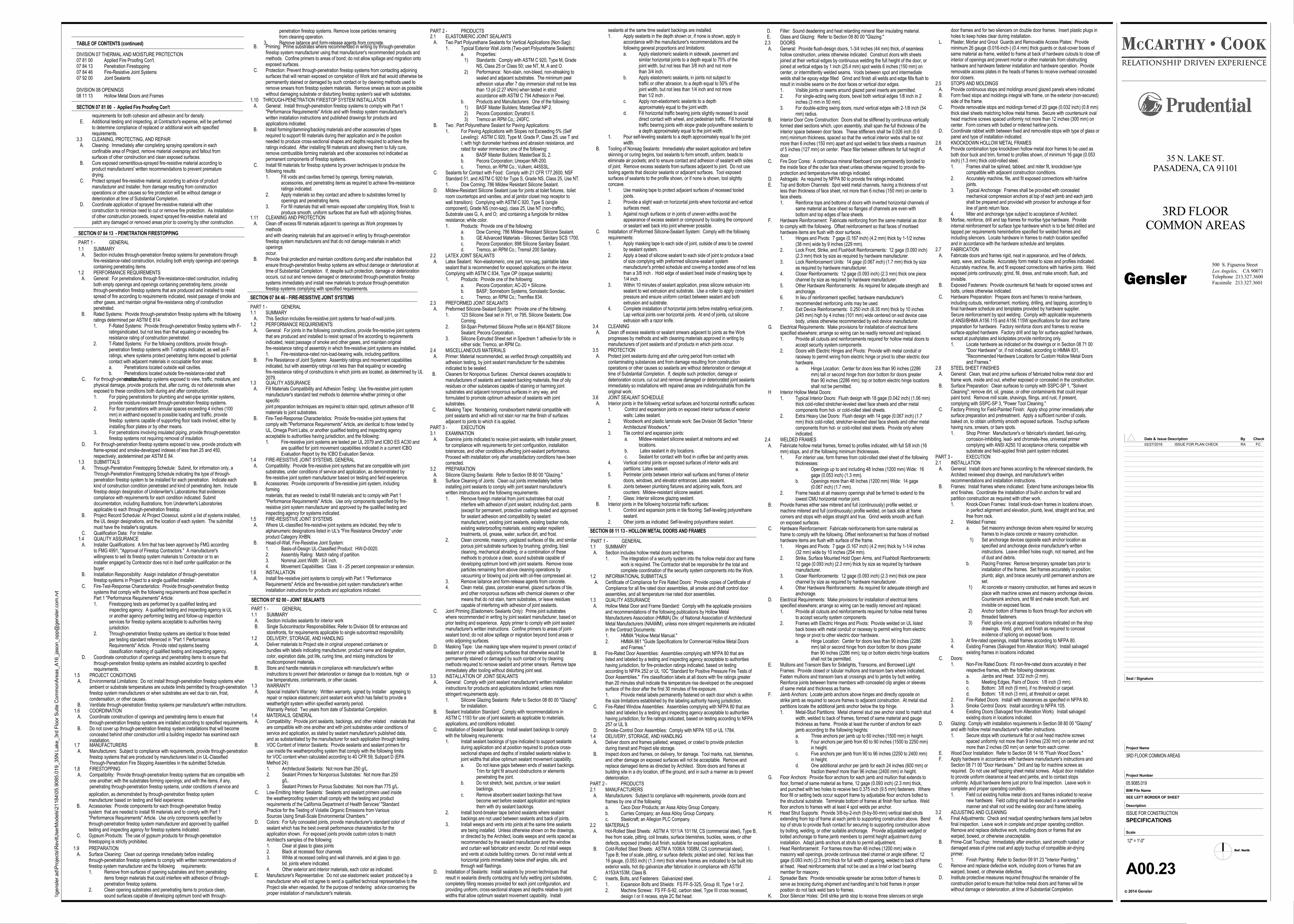
TABLE OF CONTENTS (continued)
SECTION 08 11 13 - HOLLOW METAL DOORS AND FRAMES
DIVISION 07 THERMAL AND MOISTURE PROTECTION07 81 00 Applied Fire Proofing Con't.07 84 13 Penetration Firestopping07 84 46 Fire-Resistive Joint Systems07 92 00 Joint Sealants
DIVISION 08 OPENINGS08 11 13 Hollow Metal Doors and Frames
d. Fill horizontal traffic bearing joints slightly recessed to avoid direct contact with wheel, and pedestrian traffic. Fill horizontal traffic bearing joints with slope grade polyurethane sealants to a depth approximately equal to the joint width.
1. Pour self-leveling sealants to a depth approximately equal to the joint width.
B. Tooling of Nonsag Sealants: Immediately after sealant application and beforeskinning or curing begins, tool sealants to form smooth, uniform, beads toeliminate air pockets; and to ensure contact and adhesion of sealant with sidesof joint. Remove excess sealants from surfaces adjacent to joint. Do not usetooling agents that discolor sealants or adjacent surfaces. Tool exposedsurfaces of sealants to the profile shown, or if none is shown, tool slightlyconcave.1. Use masking tape to protect adjacent surfaces of recessed tooled
joints.2. Provide a slight wash on horizontal joints where horizontal and vertical
surfaces meet.3. Against rough surfaces or in joints of uneven widths avoid the
appearance of excess sealant or compound by locating the compound or sealant well back into joint wherever possible.
C. Installation of Preformed Silicone-Sealant System: Comply with the followingrequirements:1. Apply masking tape to each side of joint, outside of area to be covered
by sealant system.2. Apply a bead of silicone sealant to each side of joint to produce a bead
of size complying with preformed silicone-sealant system manufacturer's printed schedule and covering a bonded area of not lessthan a 3/8 inch . Hold edge of sealant bead inside of masking tape by 1/4 inch .
3. Within 10 minutes of sealant application, press silicone extrusion into sealant to wet extrusion and substrate. Use a roller to apply consistent pressure and ensure uniform contact between sealant and both extrusion and substrate.
4. Complete installation of horizontal joints before installing vertical joints.Lap vertical joints over horizontal joints. At end of joints, cut silicone extrusion with a razor knife.
3.4 CLEANING A. Clean off excess sealants or sealant smears adjacent to joints as the Work
progresses by methods and with cleaning materials approved in writing bymanufacturers of joint sealants and of products in which joints occur.
3.5 PROTECTION A. Protect joint sealants during and after curing period from contact with
contaminating substances and from damage resulting from constructionoperations or other causes so sealants are without deterioration or damage attime of Substantial Completion. If, despite such protection, damage ordeterioration occurs, cut out and remove damaged or deteriorated joint sealantsimmediately so installations with repaired areas are indistinguishable from theoriginal work.
3.6 JOINT SEALANT SCHEDULE A. Interior joints in the following vertical surfaces and horizontal nontraffic surfaces:
1. Control and expansion joints on exposed interior surfaces of exterior walls: Latex sealant.
2. Woodwork and plastic laminate work: See Division 06 Section "Interior Architectural Woodwork."
3. Tile control and expansion joints: a. Mildew-resistant silicone sealant at restrooms and wet
locations. b. Latex sealant in dry locations. c. Sealant for contact with food in coffee bar and pantry areas.
4. Vertical control joints on exposed surfaces of interior walls and partitions: Latex sealant.
5. Perimeter joints between interior wall surfaces and frames of interior doors, windows, and elevator entrances: Latex sealant.
6. Joints between plumbing fixtures and adjoining walls, floors, and counters: Mildew-resistant silicone sealant.
7. Glass: Interior silicone glazing sealant. B. Interior joints in the following horizontal traffic surfaces:
1. Control and expansion joints in tile flooring: Self-leveling polyurethane sealant.
2. Other joints as indicated: Self-leveling polyurethane sealant.
1.1 SUMMARY A. Section includes hollow metal doors and frames.
1. The integration of a security system into the hollow metal door and framework is required. The Contractor shall be responsible for the total and complete coordination of the security system components into the Work.
1.2 INFORMATIONAL SUBMITTALS A. Certificate of Compliance for Fire Rated Doors: Provide copies of Certificate of
Compliance for all fire rated door assemblies, all smoke and draft control doorassemblies, and all temperature rise rated door assemblies.
1.3 QUALITY ASSURANCE A. Hollow Metal Door and Frame Standard: Comply with the applicable provisions
and recommendations of the following publications by Hollow MetalManufacturers Association (HMMA) Div. of National Association of ArchitecturalMetal Manufacturers (NAAMM), unless more stringent requirements are indicatedin the Contract Documents:1. HMMA "Hollow Metal Manual."2. HMMA 861 "Guide Specifications for Commercial Hollow Metal Doors
and Frames." B. Fire-Rated Door Assemblies: Assemblies complying with NFPA 80 that are
listed and labeled by a testing and inspecting agency acceptable to authoritieshaving jurisdiction, for fire-protection ratings indicated, based on testingaccording to NFPA 252 or UL 10C "Standard for Positive Pressure Fire Tests ofDoor Assemblies." Fire classification labels at all doors with fire ratings greaterthan 20 minutes shall indicate the temperature rise developed on the unexposedsurface of the door after the first 30 minutes of fire exposure.1. Provide metal labels permanently fastened on each door which is withinthe size limitations established by the labeling authority having jurisdiction.
C. Fire-Rated Window Assemblies: Assemblies complying with NFPA 80 that arelisted and labeled by a testing and inspecting agency acceptable to authoritieshaving jurisdiction, for fire ratings indicated, based on testing according to NFPA257 or UL 9.
D. Smoke-Control Door Assemblies: Comply with NFPA 105 or UL 1784.1.4 DELIVERY, STORAGE, AND HANDLING A. Deliver doors and frames palleted, wrapped, or crated to provide protection
during transit and Project site storage. B. Inspect doors and frames, on delivery, for damage. Tool marks, rust, blemishes,
and other damage on exposed surfaces will not be acceptable. Remove andreplace damaged items as directed by Architect. Store doors and frames atbuilding site in a dry location, off the ground, and in such a manner as to preventdeterioration.
PART 2 - PRODUCTS2.1 MANUFACTURERS A. Manufacturers: Subject to compliance with requirements, provide doors and
frames by one of the following:a. Ceco Door Products; an Assa Abloy Group Company.b. Curries Company; an Assa Abloy Group Company.c. Steelcraft; an Allegion PLC Company.
2.2 MATERIALS A. Hot-Rolled Steel Sheets: ASTM A 1011/A 1011M, CS (commercial steel), Type B,
free from scale, pitting, coil breaks, surface blemishes, buckles, waves, or otherdefects, exposed (matte) dull finish, suitable for exposed applications.
B. Cold-Rolled Steel Sheets: ASTM A 1008/A 1008M, CS (commercial steel), Type B; free of scale, pitting, or surface defects; pickled and oiled. Not less than16 gauge, (0.053 inch) (1.3 mm) thick where frames are indicated to be built intoexterior walls, hot dip galvanize after fabrication in compliance with ASTMA153/A153M, Class B.
C. Inserts, Bolts, and Fasteners: Galvanized steel.1. Expansion Bolts and Shields: FS FF-S-325, Group III, Type 1 or 2.
2. Machine Screws: FS FF-S-92, carbon steel, Type III cross recessed, design I or II recess, style 2C flat head.
SECTION 07 84 13 - PENETRATION FIRESTOPPING
SECTION 07 92 00 - JOINT SEALANTS
SECTION 07 84 46 - FIRE-RESISTIVE JOINT SYSTEMS
1.1 SUMMARY A. Section includes through-penetration firestop systems for penetrations through
fire-resistance-rated construction, including both empty openings and openingscontaining penetrating items.
1.2 PERFORMANCE REQUIREMENTS A. General: For penetrations through fire-resistance-rated construction, including
both empty openings and openings containing penetrating items, providethrough-penetration firestop systems that are produced and installed to resistspread of fire according to requirements indicated, resist passage of smoke andother gases, and maintain original fire-resistance rating of constructionpenetrated.
B. Rated Systems: Provide through-penetration firestop systems with the followingratings determined per ASTM E 814:1. F-Rated Systems: Provide through-penetration firestop systems with F-
ratingsindicated, but not less than that equaling or exceeding fire-resistance rating of construction penetrated.
2. T-Rated Systems: For the following conditions, provide through-penetration firestop systems with T-ratings indicated, as well as F-ratings, where systems protect penetrating items exposed to potential contact with adjacent materials in occupiable floor areas:a. Penetrations located outside wall cavities.b. Penetrations located outside fire-resistance-rated shaft
enclosures. C. For through-penetration firestop systems exposed to view, traffic, moisture, andphysical damage, provide products that, after curing, do not deteriorate whenexposed to these conditions both during and after construction.1. For piping penetrations for plumbing and wet-pipe sprinkler systems,
provide moisture-resistant through-penetration firestop systems.2. For floor penetrations with annular spaces exceeding 4 inches (100
mm) in widthand exposed to possible loading and traffic, provide firestop systems capable of supporting floor loads involved, either by installing floor plates or by other means.
3. For penetrations involving insulated piping, provide through-penetrationfirestop systems not requiring removal of insulation.
D. For through-penetration firestop systems exposed to view, provide products withflame-spread and smoke-developed indexes of less than 25 and 450,respectively, asdetermined per ASTM E 84.
1.3 SUBMITTALS A. Through-Penetration Firestopping Schedule: Submit, for information only, a
Through-Penetration Firestopping Schedule indicating the type of through-penetration firestop system to be installed for each penetration. Indicate eachkind of construction condition penetrated and kind of penetrating item. Includefirestop design designation of Underwriter's Laboratories that evidencescompliance with requirements for each condition indicated. Submitdocumentation, including illustrations, from Underwriter's Laboratories applicable to each through-penetration firestop.
B. Project Record Schedule: At Project Closeout, submit a list of systems installed,the UL design designations, and the location of each system. The submittalmust have the Installer's signature.
C. Qualification Data: For Installer.1.4 QUALITY ASSURANCE A. Installer Qualifications: A firm that has been approved by FMG according
to FMG 4991, "Approval of Firestop Contractors." A manufacturer'swillingness to sell its firestop system materials to Contractor or to aninstaller engaged by Contractor does not in itself confer qualification on thebuyer.
B. Installation Responsibility: Assign installation of through-penetrationfirestop systems in Project to a single qualified installer.
C. Fire-Test-Response Characteristics: Provide through-penetration firestopsystems that comply with the following requirements and those specified inPart 1 "Performance Requirements" Article:1. Firestopping tests are performed by a qualified testing and
inspecting agency. A qualified testing and inspecting agency is ULor another agency performing testing and follow-up inspection services for firestop systems acceptable to authorities having jurisdiction.
2. Through-penetration firestop systems are identical to those testedper testing standard referenced in "Part 1 Performance Requirements" Article. Provide rated systems bearing classification marking of qualified testing and inspecting agency.
D. Coordinate construction of openings and penetrating items to ensure thatthrough-penetration firestop systems are installed according to specifiedrequirements.
1.5 PROJECT CONDITIONS A. Environmental Limitations: Do not install through-penetration firestop systems when
ambient or substrate temperatures are outside limits permitted by through-penetrationfirestop system manufacturers or when substrates are wet due to rain, frost,condensation, or other causes.
B. Ventilate through-penetration firestop systems per manufacturer's written instructions.1.6 COORDINATION A. Coordinate construction of openings and penetrating items to ensure that
through-penetration firestop systems are installed according to specified requirements. B. Do not cover up through-penetration firestop system installations that will become
concealed behind other construction until a building inspector has examined eachinstallation.
1.7 MANUFACTURERS A. Manufacturers: Subject to compliance with requirements, provide through-penetration
firestop systems that are produced by manufacturers listed in UL-ClassifiedThrough-Penetration Fire Stopping Assemblies in the submitted Schedule.
1.8 FIRESTOPPING A. Compatibility: Provide through-penetration firestop systems that are compatible with
one another; with the substrates forming openings; and with the items, if any,penetrating through-penetration firestop systems, under conditions of service and
application, as demonstrated by through-penetration firestop systemmanufacturer based on testing and field experience.
B. Accessories: Provide components for each through-penetration firestopsystem that are needed to install fill materials and to comply with Part 1"Performance Requirements" Article. Use only components specified bythrough-penetration firestop system manufacturer and approved by qualifiedtesting and inspecting agency for firestop systems indicated.
C. Gypsum Products: The use of gypsum products for through-penetrationfirestopping is strictly prohibited.
1.9 PREPARATION A. Surface Cleaning: Clean out openings immediately before installing
through-penetration firestop systems to comply with written recommendations offirestop system manufacturer and the following requirements:1. Remove from surfaces of opening substrates and from penetrating
items foreign materials that could interfere with adhesion of through-penetration firestop systems.
2. Clean opening substrates and penetrating items to produce clean, sound surfaces capable of developing optimum bond with through-
B. Priming: Prime substrates where recommended in writing by through-penetrationfirestop system manufacturer using that manufacturer's recommended products andmethods. Confine primers to areas of bond; do not allow spillage and migration ontoexposed surfaces.
C. Protection: Prevent through-penetration firestop systems from contacting adjoiningsurfaces that will remain exposed on completion of Work and that would otherwise bepermanently stained or damaged by such contact or by cleaning methods used toremove smears from firestop system materials. Remove smears as soon as possiblewithout damaging substrate or disturbing firestop system's seal with substrates.
1.10 THROUGH-PENETRATION FIRESTOP SYSTEM INSTALLATION A. General: Install through-penetration firestop systems to comply with Part 1
"Performance Requirements" Article and with firestop system manufacturer'swritten installation instructions and published drawings for products andapplications indicated.
B. Install forming/damming/backing materials and other accessories of typesrequired to support fill materials during their application and in the positionneeded to produce cross-sectional shapes and depths required to achieve fireratings indicated. After installing fill materials and allowing them to fully cure,remove combustible forming materials and other accessories not indicated aspermanent components of firestop systems.
C. Install fill materials for firestop systems by proven techniques to produce thefollowing results:1. Fill voids and cavities formed by openings, forming materials,
accessories, and penetrating items as required to achieve fire-resistanceratings indicated.
2. Apply materials so they contact and adhere to substrates formed by openings and penetrating items.
3. For fill materials that will remain exposed after completing Work, finish toproduce smooth, uniform surfaces that are flush with adjoining finishes.
1.11 CLEANING AND PROTECTION A. Clean off excess fill materials adjacent to openings as Work progresses by
methodsand with cleaning materials that are approved in writing by through-penetrationfirestop system manufacturers and that do not damage materials in whichopeningsoccur.
B. Provide final protection and maintain conditions during and after installation thatensure through-penetration firestop systems are without damage or deterioration attime of Substantial Completion. If, despite such protection, damage or deteriorationoccurs, cut out and remove damaged or deteriorated through-penetration firestopsystems immediately and install new materials to produce through-penetrationfirestop systems complying with specified requirements.
1.1 SUMMARY A. This Section includes fire-resistive joint systems for head-of-wall joints.1.2 PERFORMANCE REQUIREMENTS A. General: For joints in the following constructions, provide fire-resistive joint systems
that are produced and installed to resist spread of fire according to requirementsindicated, resist passage of smoke and other gases, and maintain originalfire-resistance rating of assembly in which fire-resistive joint systems are installed.1. Fire-resistance-rated non-load-bearing walls, including partitions.
B. Fire Resistance of Joint Systems: Assembly ratings and movement capabilitiesindicated, but with assembly ratings not less than that equaling or exceedingfire-resistance rating of constructions in which joints are located, as determined by UL2079.
1.3 QUALITY ASSURANCE A. Fill Materials Compatibility and Adhesion Testing: Use fire-resistive joint system
manufacturer's standard test methods to determine whether priming or otherspecificjoint preparation techniques are required to obtain rapid, optimum adhesion of fillmaterials to joint substrates.
B. Fire-Test-Response Characteristics: Provide fire-resistive joint systems thatcomply with "Performance Requirements" Article, are identical to those tested byUL, Omega Point Labs, or another qualified testing and inspecting agencyacceptable to authorities having jurisdiction, and the following:1. Fire-resistive joint systems are tested per UL 2079 and ICBO ES AC30 and
are qualified for joint movement capabilities indicated in a current ICBO Evaluation Report by the ICBO Evaluation Service.
1.4 FIRE-RESISTIVE JOINT SYSTEMS, GENERAL A. Compatibility: Provide fire-resistive joint systems that are compatible with joint
substrates, under conditions of service and application, as demonstrated byfire-resistive joint system manufacturer based on testing and field experience.
B. Accessories: Provide components of fire-resistive joint system, includingformingmaterials, that are needed to install fill materials and to comply with Part 1"Performance Requirements" Article. Use only components specified by fire-resistive joint system manufacturer and approved by the qualified testing andinspecting agency for systems indicated.
1.5 FIRE-RESISTIVE JOINT SYSTEMS A. Where UL-classified fire-resistive joint systems are indicated, they refer to
alphanumeric designations listed in UL's "Fire Resistance Directory" underproduct Category XHBN.
B. Head-of-Wall, Fire-Resistive Joint System:1. Basis-of-Design UL-Classified Product: HW-D-0020.2. Assembly Rating: Match rating of partition.3. Nominal Joint Width: 3/4 inch.4. Movement Capabilities: Class II - 25 percent compression or extension.
1.6 INSTALLATION A. Install fire-resistive joint systems to comply with Part 1 "Performance
Requirements" Article and fire-resistive joint system manufacturer's writteninstallation instructions for products and applications indicated.
PART 1 - GENERAL1.1 SUMMARY A. Section includes sealants for interior work B. Single Subcontractor Responsibilities: Refer to Division 08 for entrances and
storefronts, for requirements applicable to single subcontract responsibility.1.2 DELIVERY, STORAGE, AND HANDLING A. Deliver materials to Project site in original unopened containers or
bundles with labels indicating manufacturer, product name and designation,color, expiration date, pot life, curing time, and mixing instructions formulticomponent materials.
B. Store and handle materials in compliance with manufacturer's writteninstructions to prevent their deterioration or damage due to moisture, high orlow temperatures, contaminants, or other causes.
1.3 WARRANTY A. Special Installer's Warranty: Written warranty, signed by Installer agreeing to
repair or replace elastomeric joint sealant work which has failed to provide aweathertight system within specified warranty period.Warranty Period: Two years from date of Substantial Completion.
1.4 MATERIALS, GENERAL A. Compatibility: Provide joint sealants, backings, and other related materials that
are compatible with one another and with joint substrates under conditions ofservice and application, as stated by sealant manufacturer's published data,and as substantiated by the manufacturer for each application through testing.
B. VOC Content of Interior Sealants: Provide sealants and sealant primers foruse inside the weatherproofing system that comply with the following limitsfor VOC content when calculated according to 40 CFR 59, Subpart D (EPAMethod 24):1. Architectural Sealants: Not more than 250 g/L.2. Sealant Primers for Nonporous Substrates: Not more than 250
g/L.3. Sealant Primers for Porous Substrates: Not more than 775 g/L.
C. Low-Emitting Interior Sealants: Sealants and sealant primers used insidethe weatherproofing system shall comply with the testing and productrequirements of the California Department of Health Services' "StandardPractice for the Testing of Volatile Organic Emissions from VariousSources Using Small-Scale Environmental Chambers."
D. Colors: For fully concealed joints, provide manufacturer's standard color ofsealant which has the best overall performance characteristics for theapplication shown. For exposed joints provide custom colors to matchArchitect's samples of the following:1. Clear at glass to glass joints2. Black at recessed floor channels3. White at recessed ceiling and wall channels, and at glass to gyp.
bd. joints where indicated.4. Other exterior and interior materials, each color as indicated.
E. Manufacturer's Representative: Do not use elastomeric sealant produced by amanufacturer who will not agree to send a qualified technical representative to theProject site when requested, for the purpose of rendering advice concerning theproper installation of manufacturer's materials.
2.1 ELASTOMERIC JOINT SEALANTS A. Two Part Polyurethane Sealants for Vertical Applications (Non-Sag):
1. Typical Exterior Wall Joints (Two-part Polyurethane Sealants):a. Properties: 1) Standards: Comply with ASTM C 920, Type M, Grade
NS, Class 25 or Class 50; use NT, M, A and O. 2) Performance: Non-stain, non-bleed, non-streaking to
sealed and adjacent substrates. The minimum peeladhesion value after 7 day immersion shall not be lessthan 13 pli (2.27 kN/m) when tested in strict accordance with ASTM C 794 Adhesion in Peel.
b. Products and Manufacturers: One of the following: 1) BASF Master Builders; MasterSeal NP 2. 2) Pecora Corporation; Dynatrol II. 3) Tremco an RPM Co,; 240FC.
B. Two‑Part Polyurethane Sealant for Paving Applications:1. For Paving Applications with Slopes not Exceeding 5% (Self
Leveling): ASTM C 920, Type M, Grade P, Class 25; use T andI; with high durometer hardness and abrasion resistance, andrated for water immersion; one of the following:a. BASF Master Builders; MasterSeal SL 2.b. Pecora Corporation; Urexpan NR-200.c. Tremco, an RPM Co.; Vulkem, 445SSL.
C. Sealants for Contact with Food: Comply with 21 CFR 177.2600, NSFStandard 51, and ASTM C 920 for Type S, Grade NS, Class 25, Use NT.1. Dow Corning; 786 Mildew Resistant Silicone Sealant.
D. Mildew-Resistant Silicone Sealant (use for joints at toilet fixtures, toiletroom countertops and vanities, and at janitor closet mop receptor towall transition): Complying with ASTM C 920, Type S (singlecomponent), Grade NS (non-sag), class 25, Use NT (non-traffic),Substrate uses G, A, and O; and containing a fungicide for mildewresistance; white color.1. Products: Provide one of the following:
a. Dow Corning; 786 Mildew Resistant Silicone Sealant.b. GE Advanced Materials - Silicones; Sanitary SCS 1700.c. Pecora Corporation; 898 Silicone Sanitary Sealant.d. Tremco, an RPM Co.; Tremsil 200 Sanitary.
2.2 LATEX JOINT SEALANTS A. Latex Sealant: Non-elastomeric, one part, non-sag, paintable latex
sealant that is recommended for exposed applications on the interior.Complying with ASTM C 834, Type OP (opaque sealants):1. Products: Provide one of the following:
a. Pecora Corporation; AC-20 + Silicone.b. BASF; Sonneborn Systems, Sonolastic Sonolac.c. Tremco, an RPM Co.; Tremflex 834.
2.3 PREFORMED JOINT SEALANTS A. Preformed Silicone-Sealant System: Provide one of the following.
1. 123 Silicone Seal set in 791, or 795, Silicone Sealants; DowCorning.
2. Sil-Span Preformed Silicone Profile set in 864-NST Silicone Sealant; Pecora Corporation.
3. Silicone Extruded Sheet set in Spectrem 1 adhesive for bite ineither side; Tremco, an RPM Co.
2.4 MISCELLANEOUS MATERIALS A. Primer: Material recommended, as verified through compatibility and
adhesion testing, by joint sealant manufacturer for the substratesindicated to be sealed.
B. Cleaners for Nonporous Surfaces: Chemical cleaners acceptable tomanufacturers of sealants and sealant backing materials, free of oilyresidues or other substances capable of staining or harming jointsubstrates and adjacent nonporous surfaces in any way, andformulated to promote optimum adhesion of sealants with jointsubstrates.
C. Masking Tape: Nonstaining, nonabsorbent material compatible withjoint sealants and which will not stain nor mar the finish of surfacesadjacent to joints to which it is applied.
PART 3 - EXECUTION3.1 EXAMINATION A. Examine joints indicated to receive joint sealants, with Installer present,
for compliance with requirements for joint configuration, installationtolerances, and other conditions affecting joint-sealant performance.Proceed with installation only after unsatisfactory conditions have beencorrected.
3.2 PREPARATION A. Silicone Glazing Sealants: Refer to Section 08 80 00 "Glazing." B. Surface Cleaning of Joints: Clean out joints immediately before
installing joint sealants to comply with joint sealant manufacturer'swritten instructions and the following requirements:1. Remove foreign material from joint substrates that could
interfere with adhesion of joint sealant, including dust, paints(except for permanent, protective coatings tested and approvedfor sealant adhesion and compatibility by sealant manufacturer), existing joint sealants, existing backer rods, existing waterproofing materials, existing water repellent treatments, oil, grease, water, surface dirt, and frost.
2. Clean concrete, masonry, unglazed surfaces of tile, and similarporous joint substrate surfaces by brushing, grinding, blast cleaning, mechanical abrading, or a combination of these methods to produce a clean, sound substrate capable of developing optimum bond with joint sealants. Remove looseparticles remaining from above cleaning operations by vacuuming or blowing out joints with oil-free compressed air.
3. Remove laitance and form-release agents from concrete.4. Clean metal, glass, porcelain enamel, glazed surfaces of tile,
and other nonporous surfaces with chemical cleaners or othermeans that do not stain, harm substrates, or leave residuescapable of interfering with adhesion of joint sealants.
C. Joint Priming (Elastomeric Sealants Only): Prime joint substrates where recommended in writing by joint sealant manufacturer, based onprior testing and experience. Apply primer to comply with joint sealantmanufacturer's written instructions. Confine primers to areas of joint-sealant bond; do not allow spillage or migration beyond bond areas oronto adjoining surfaces.
D. Masking Tape: Use masking tape where required to prevent contact ofsealant or primer with adjoining surfaces that otherwise would bepermanently stained or damaged by such contact or by cleaningmethods required to remove sealant and primer smears. Remove tapeimmediately after tooling without disturbing joint seal.
3.3 INSTALLATION OF JOINT SEALANTS A. General: Comply with joint sealant manufacturer's written installation
instructions for products and applications indicated, unless morestringent requirements apply.1. Silicone Glazing Sealants: Refer to Section 08 80 00 "Glazing"
for installation. B. Sealant Installation Standard: Comply with recommendations in
ASTM C 1193 for use of joint sealants as applicable to materials,applications, and conditions indicated.
C. Installation of Sealant Backings: Install sealant backings to complywith the following requirements:1. Install sealant backings of type indicated to support sealants
during application and at position required to produce cross-sectional shapes and depths of installed sealants relative tojoint widths that allow optimum sealant movement capability.a. Do not leave gaps between ends of sealant backings.
Trim for tight fit around obstructions or elements penetrating the joint.
b. Do not stretch, twist, puncture, or tear sealant backings.
c. Remove absorbent sealant backings that have become wet before sealant application and replace them with dry sealant backings.
2. Install bond-breaker tape behind sealants where sealant backings are not used between sealants and back of joints.
3. Install weeps and vents into joints at the same time sealantsare being installed. Unless otherwise shown on the drawings,or directed by the Architect, locate weeps and vents spaced asrecommended by the sealant manufacturer and the window and curtain wall fabricator and erector. Do not install weeps and vents at outside building corners. Do not install vents athorizontal joints immediately below shelf angles, sills, and through wall flashings.
D. Installation of Sealants: Install sealants by proven techniques thatresult in sealants directly contacting and fully wetting joint substrates,completely filling recesses provided for each joint configuration, andproviding uniform, cross-sectional shapes and depths relative to jointwidths that allow optimum sealant movement capability. Install
2.6 KNOCKDOWN HOLLOW METAL FRAMES A. Provide combination type knockdown hollow metal door frames to be used as
both door buck and trim, formed to profiles shown, of minimum 16 gage (0.053inch) (1.3 mm) thick cold-rolled steel.1. Frames shall be splined, tabbed, and miter fit, knockdown type
compatible with adjacent construction conditions.2. Accurately machine, file, and fit exposed connections with hairline
joints.3. Typical Anchorage: Frames shall be provided with concealed
mechanical compression anchors at top of each jamb and each jambshall be prepared and provided with provision for anchorage at floorline of jamb return face.
4. Miter and anchorage type subject to acceptance of Architect. B. Mortise, reinforce, drill and tap frames for mortise type hardware. Provide
internal reinforcement for surface type hardware which is to be field drilled andtapped per requirements hereinbefore specified for welded frames andincluding silencers. Locate hardware in frames to match location specifiedand in accordance with the hardware schedule and templates.
2.7 FABRICATION A. Fabricate doors and frames rigid, neat in appearance, and free of defects,
warp, wave, and buckle. Accurately form metal to sizes and profiles indicated.Accurately machine, file, and fit exposed connections with hairline joints. Weldexposed joints continuously; grind, fill, dress, and make smooth, flush, andinvisible.
B. Exposed Fasteners: Provide countersunk flat heads for exposed screws andbolts, unless otherwise indicated.
C. Hardware Preparation: Prepare doors and frames to receive hardware,including cutouts, reinforcement, mortising, drilling, and tapping, according tofinal hardware schedule and templates provided by hardware supplier.Secure reinforcement by spot welding. Comply with applicable requirementsof ANSI/BHMA A156.115 and A156.115W specifications for door and framepreparation for hardware. Factory reinforce doors and frames to receivesurface-applied hardware. Factory drill and tap for surface-applied hardware,except at pushplates and kickplates provide reinforcing only.1. Locate hardware as indicated on the drawings or in Section 08 71 00
"Door Hardware" or, if not indicated, according to HMMA 831, "Recommended Hardware Locations for Custom Hollow Metal Doorsand Frames."
2.8 STEEL SHEET FINISHES A. General: Clean, treat and prime surfaces of fabricated hollow metal door and
frame work, inside and out, whether exposed or concealed in the construction. B. Surface Preparation: Clean surfaces to comply with SSPC-SP 1, "Solvent
Cleaning"; remove dirt, oil, grease, or other contaminants that could impairpaint bond. Remove mill scale, shavings, filings, and rust, if present,complying with SSPC-SP 3, "Power Tool Cleaning."
C. Factory Priming for Field-Painted Finish: Apply shop primer immediately aftersurface preparation and pretreatment. Apply a sufficient number of coats,baked on, to obtain uniformly smooth exposed surfaces. Touchup surfaceshaving runs, smears, or bare spots.1. Shop Primer: Manufacturer's or fabricator's standard, fast-curing,
corrosion-inhibiting, lead- and chromate-free, universal primer complying with ANSI A250.10 acceptance criteria; compatible withsubstrate and field-applied finish paint system indicated.
PART 3 - EXECUTION2.1 INSTALLATION A. General: Install doors and frames according to the referenced standards, the
Architect reviewed shop drawings, and manufacturer's writtenrecommendations and installation instructions.
B. Frames: Install frames where indicated. Extend frame anchorages below fillsand finishes. Coordinate the installation of built-in anchors for wall andpartition construction as required with other work.1. Knock-Down Frames: Install knock-down frames in locations shown,
in perfect alignment and elevation, plumb, level, straight and true, andfree from rack.
2. Welded Frames:a. Set masonry anchorage devices where required for securing
frames to in-place concrete or masonry construction. 1) Set anchorage devices opposite each anchor location as
specified and anchorage device manufacturer's written instructions. Leave drilled holes rough, not reamed, and freeof dust and debris.
b. Placing Frames: Remove temporary spreader bars prior toinstallation of the frames. Set frames accurately in position;plumb; align, and brace securely until permanent anchors areset.
1) At concrete or masonry construction, set frames and secure inplace with machine screws and masonry anchorage devices.Countersink anchors, and fill and make smooth, flush, andinvisible on exposed faces.
2) Anchor bottom of frames to floors through floor anchors withthreaded fasteners.
3) Field splice only at approved locations indicated on the shopdrawings. Weld, grind, and finish as required to conceal evidence of splicing on exposed faces.
3. At fire-rated openings, install frames according to NFPA 80.4. Existing Frames (Salvaged from Alteration Work): Install salvaged
existing frames in locations indicated. C. Doors:
1. Non-Fire Rated Doors: Fit non-fire-rated doors accurately in their respective frames, with the following clearances:a. Jambs and Head: 3/32 inch (2 mm).b. Meeting Edges, Pairs of Doors: 1/8 inch (3 mm).c. Bottom: 3/8 inch (9 mm), if no threshold or carpet.d. Bottom: 1/8 inch (3 mm), at threshold or carpet.
2. Fire-Rated Doors: Install with clearances as specified in NFPA 80.3. Smoke Control Doors: Install according to NFPA 105.4. Existing Doors (Salvaged from Alteration Work): Install salvaged
existing doors in locations indicated. D. Glazing: Comply with installation requirements in Section 08 80 00 "Glazing"
and with hollow metal manufacturer's written instructions.1. Secure stops with countersunk flat or oval head machine screws
spaced uniformly not more than 9 inches (230 mm) on center and notmore than 2 inches (50 mm) on center from each corner.
E. Wood Door Installation: Refer to Section 08 14 16 "Flush Wood Doors." F. Apply hardware in accordance with hardware manufacturer's instructions and
Section 08 71 00 "Door Hardware." Drill and tap for machine screws asrequired. Do not use self tapping sheet metal screws. Adjust door installationto provide uniform clearance at head and jambs, and to contact stopsuniformly. Adjust hardware items just prior to final inspection. Leave work incomplete and proper operating condition.1. Field cut existing hollow metal doors and frames indicated to receive
new hardware. Field cutting shall be executed in a workmanlike manner and shall not void the existing door and frame labeling.
3.2 ADJUSTING AND CLEANING A. Final Adjustments: Check and readjust operating hardware items just before
final inspection. Leave work in complete and proper operating condition.Remove and replace defective work, including doors or frames that arewarped, bowed, or otherwise unacceptable.
B. Prime-Coat Touchup: Immediately after erection, sand smooth rusted ordamaged areas of prime coat and apply touchup of compatible air-dryingprimer.1. Finish Painting: Refer to Section 09 91 23 "Interior Painting."
C. Remove and replace defective work, including doors or frames that arewarped, bowed, or otherwise defective.
D. Institute protective measures required throughout the remainder of theconstruction period to ensure that hollow metal doors and frames will bewithout damage or deterioration, at time of Substantial Completion.
D. Astragals: As required by NFPA 80 to provide fire ratings indicated. E. Top and Bottom Channels: Spot weld metal channels, having a thickness of not
less than thickness of face sheet, not more than 6 inches (150 mm) on center toface sheets.1. Reinforce tops and bottoms of doors with inverted horizontal channels of
same material as face sheet so flanges of channels are even with bottom and top edges of face sheets.
F. Hardware Reinforcement: Fabricate reinforcing from the same material as doorto comply with the following. Offset reinforcement so that faces of mortisedhardware items are flush with door surfaces.1. Hinges and Pivots: 7 gage (0.167 inch) (4.2 mm) thick by 1-1/2 inches
(38 mm) wide by 9 inches (229 mm).2. Lock Front, Strike, and Flushbolt Reinforcements: 12 gage (0.093 inch)
(2.3 mm) thick by size as required by hardware manufacturer.3. Lock Reinforcement Units: 14 gage (0.067 inch) (1.7 mm) thick by size
as required by hardware manufacturer.4. Closer Reinforcements: 12 gage (0.093 inch) (2.3 mm) thick one piece
channel by size as required by hardware manufacturer.5. Other Hardware Reinforcements: As required for adequate strength and
anchorage.6. In lieu of reinforcement specified, hardware manufacturer's
recommended reinforcing units may be used.7. Exit Device Reinforcements: 0.250 inch (6.35 mm) thick by 10 inches
(245 mm) high by 4 inches (101 mm) wide centered on exit device casebody, unless otherwise recommended by exit device manufacturer.
G. Electrical Requirements: Make provisions for installation of electrical itemsspecified elsewhere; arrange so wiring can be readily removed and replaced.1. Provide all cutouts and reinforcements required for hollow metal doors to
accept security system components.2. Doors with Electric Hinges and Pivots: Provide with metal conduit or
raceway to permit wiring from electric hinge or pivot to other electric doorhardware.a. Hinge Location: Center for doors less than 90 inches (2286
mm) tall or second hinge from door bottom for doors greater than 90 inches (2286 mm); top or bottom electric hinge locationsshall not be permitted.
H Interior Hollow Metal Doors:1. Typical Interior Doors: Flush design with 18 gage (0.042 inch) (1.06 mm)
thick cold-rolled stretcher-leveled steel face sheets and other metal components from hot- or cold-rolled steel sheets.
2. Extra Heavy Use Doors: Flush design with 14 gage (0.067 inch) (1.7 mm) thick cold-rolled, stretcher-leveled steel face sheets and other metalcomponents from hot- or cold-rolled steel sheets. Provide only where indicated.
2.4 WELDED FRAMES A. Fabricate hollow metal frames, formed to profiles indicated, with full 5/8 inch (16
mm) stops, and of the following minimum thicknesses.1. For interior use, form frames from cold-rolled steel sheet of the following
thicknesses:a. Openings up to and including 48 Inches (1200 mm) Wide: 16
gage (0.053 inch) (1.3 mm).b. Openings more than 48 Inches (1200 mm) Wide: 14 gage
(0.067 inch) (1.7 mm).2. Frame heads at all masonry openings shall be formed to extend to the
lowest CMU horizontal mortar joint. B. Provide frames either saw mitered and full (continuously) profile welded, or
machine mitered and full (continuously) profile welded, on back side at framecorners and stops with edges straight and true. Grind welds smooth and flushon exposed surfaces.
C. Hardware Reinforcement: Fabricate reinforcements from same material asframe to comply with the following. Offset reinforcement so that faces of mortisedhardware items are flush with surface of the frame.1. Hinges and Pivots: 7 gage (0.167 inch) (4.2 mm) thick by 1-1/4 inches
(32 mm) wide by 10 inches (254 mm).2. Strike, Surface Mounted Hold Open Arms, and Flushbolt Reinforcements:
12 gage (0.093 inch) (2.3 mm) thick by size as required by hardware manufacturer.
3. Closer Reinforcements: 12 gage (0.093 inch) (2.3 mm) thick one piecechannel by size as required by hardware manufacturer.
4. Other Hardware Reinforcements: As required for adequate strength andanchorage.
D. Electrical Requirements: Make provisions for installation of electrical itemsspecified elsewhere; arrange so wiring can be readily removed and replaced.1. Provide all cutouts and reinforcements required for hollow metal frames
to accept security system components.2. Frames with Electric Hinges and Pivots: Provide welded on UL listed
back boxes with metal conduit or raceway to permit wiring from electric hinge or pivot to other electric door hardware.a. Hinge Location: Center for doors less than 90 inches (2286
mm) tall or second hinge from door bottom for doors greater than 90 inches (2286 mm); top or bottom electric hinge locationsshall not be permitted.
E. Mullions and Transom Bars for Sidelights, Transoms, and Borrowed LightFrames: Provide closed or tubular mullions and transom bars where indicated.Fasten mullions and transom bars at crossings and to jambs by butt welding.Reinforce joints between frame members with concealed clip angles or sleevesof same metal and thickness as frame.
F. Jamb Anchors: Locate jamb anchors above hinges and directly opposite onstrike jamb as required to secure frames to adjacent construction. At metal studpartitions locate the additional jamb anchor below the top hinge.1. Metal-Stud Partitions: Metal channel stud zee anchor sized to match stud
width, welded to back of frames, formed of same material and gauge thickness as frame. Provide at least the number of anchors for each jamb according to the following heights:a. Three anchors per jamb up to 60 inches (1500 mm) in height.b. Four anchors per jamb from 60 to 90 inches (1500 to 2250 mm)
in height.c. Five anchors per jamb from 90 to 96 inches (2250 to 2400 mm)
in height.d. One additional anchor per jamb for each 24 inches (600 mm) or
fraction thereof more than 96 inches (2400 mm) in height. G. Floor Anchors: Provide floor anchors for each jamb and mullion that extends to
floor, formed of same material as frame, 12 gage (0.093 inch) (2.3 mm) thick,and punched with two holes to receive two 0.375 inch (9.5 mm) fasteners. Wherefloor fill or setting beds occur support frame by adjustable floor anchors bolted tothe structural substrate. Terminate bottom of frames at finish floor surface. Weldfloor anchors to frames with at least 4 spot welds per anchor.
H. Head Strut Supports: Provide 3/8-by-2-inch (9-by-50-mm) vertical steel strutsextending from top of frame at each jamb to supporting construction above. Bendtop of struts to provide flush contact for securing to supporting construction aboveby bolting, welding, or other suitable anchorage. Provide adjustable wedged orbolted anchorage to frame jamb members to permit height adjustment duringinstallation. Adapt jamb anchors at struts to permit adjustment.
I. Head Reinforcement: For frames more than 48 inches (1200 mm) wide inmasonry wall openings, provide continuous steel channel or angle stiffener, 12gage (0.093 inch) (2.3 mm) thick for full width of opening, welded to back of frameat head. Head reinforcements shall not be used as a lintel or load bearingmember for masonry.
J. Spreader Bars: Provide removable spreader bar across bottom of frames to serve as bracing during shipment and handling and to hold frames in properposition do not tack weld bars to frames.
K. Door Silencer Holes: Drill strike jamb stop to receive three silencers on single
requirements for both cohesion and adhesion and for density. E. Additional testing and inspecting, at Contractor's expense, will be performed
to determine compliance of replaced or additional work with specifiedrequirements.
3.3 CLEANING, PROTECTING, AND REPAIR A. Cleaning: Immediately after completing spraying operations in each
confinable area of Project, remove material overspray and fallout fromsurfaces of other construction and clean exposed surfaces.
B. Cure exposed cementitious-sprayed fire-resistive material according toproduct manufacturers' written recommendations to prevent prematuredrying.
C. Protect sprayed fire-resistive material, according to advice of productmanufacturer and Installer, from damage resulting from constructionoperations or other causes so fire protection will be without damage ordeterioration at time of Substantial Completion.
D. Coordinate application of sprayed fire-resistive material with otherconstruction to minimize need to cut or remove fire protection. As installationof other construction proceeds, inspect sprayed fire-resistive material andpatch any damaged or removed areas prior to covering by other construction.
SECTION 07 81 00 - Applied Fire Proofing Con't
PART 1 - GENERAL
penetration firestop systems. Remove loose particles remaining from cleaning operation.
3. Remove laitance and form-release agents from concrete.
PART 1 - GENERAL
PART 2 - PRODUCTS sealants at the same time sealant backings are installed.1. Apply sealants in the depth shown or, if none is shown, apply in
accordance with the manufacturer's recommendations and the following general proportions and limitations:a. Apply elastomeric sealants in sidewalk, pavement and
similar horizontal joints to a depth equal to 75% of the joint width, but not less than 3/8 inch and not more than 3/4 inch.
b. Apply elastomeric sealants, in joints not subject to traffic or other abrasion, to a depth equal to 50% of the joint width, but not less than 1/4 inch and not more than 1/2 inch .
c. Apply non-elastomeric sealants to a depth approximately equal to the joint width.
PART 1 - GENERAL
D. Filler: Sound deadening and heat retarding mineral fiber insulating material. E. Glass and Glazing: Refer to Section 08 80 00 "Glazing."2.3 DOORS A. General: Provide flush-design doors, 1-3/4 inches (44 mm) thick, of seamless
hollow construction, unless otherwise indicated. Construct doors with sheetsjoined at their vertical edges by continuous welding the full height of the door, orjoined at vertical edges by 1 inch (25.4 mm) spot welds 6 inches (150 mm) oncenter, or intermittently welded seams. Voids between spot and intermediatewelds shall be epoxy edge filled Grind and finish all welds and edge fills flush toresult in invisible seams on the door faces or vertical door edges.1. Visible joints or seams around glazed panel inserts are permitted.2. For single-acting swing doors, bevel both vertical edges 1/8 inch in 2
inches (3 mm in 50 mm).3. For double-acting swing doors, round vertical edges with 2-1/8 inch (54
mm) radius. B. Interior Door Core Construction: Doors shall be stiffened by continuous vertically
formed steel sections which, upon assembly, shall span the full thickness of theinterior space between door faces. These stiffeners shall be 0.026 inch (0.6mm) minimum thickness, spaced so that the vertical interior webs shall be notmore than 6 inches (150 mm) apart and spot welded to face sheets a maximumof 5 inches (127 mm) on center. Place filler between stiffeners for full height ofdoor.
C. Fire Door Cores: A continuous mineral fiberboard core permanently bonded tothe inside face of the outer face sheet unless otherwise required to provide fire-protection and temperature-rise ratings indicated.
door frames and for two silencers on double door frames. Insert plastic plugs inholes to keep holes clear during installation.
L. Plaster, Mortar and Grout Guards and Removable Access Plates: Provideminimum 26 gauge (0.016-inch-) (0.4 mm) thick guards or dust-cover boxes ofsame material as frame, welded to frame at back of hardware cutouts to close offinterior of openings and prevent mortar or other materials from obstructinghardware and hardware fastener installation and hardware operation. Provideremovable access plates in the heads of frames to receive overhead concealeddoor closers.
2.5 STOPS AND MOLDINGS A. Provide continuous stops and moldings around glazed panels where indicated. B. Form fixed stops and moldings integral with frame, on the exterior (non-secured)
side of the frame. C. Provide removable stops and moldings formed of 20 gage (0.032 inch) (0.8 mm)
thick steel sheets matching hollow metal frames. Secure with countersunk ovalhead machine screws spaced uniformly not more than 12 inches (300 mm) oncenter. Form corners with butted or mitered hairline joints.
D. Coordinate rabbet width between fixed and removable stops with type of glass orpanel and type of installation indicated.
Ref. North
CA 90071Los Angeles,
2014 Gensler
Project Number
BIM File Name
Scale
Description
c
Project Name
Seal / Signature
Check
Facsimile 213.327.3601
Telephone 213.327.3600
Date & By
500 S. Figueroa Street
Issue Description
SEE LEFT BORDER OF SHEET
\\ge
nsl
er.
ad\P
roje
cts
\RevitU
serM
od
els
\21
184
\05
.90
85.0
19
_35
N L
ake
_3rd
Flo
or
Su
ite C
om
mo
nA
reas_A
16_ja
son_o
pp@
gen
sle
r.com
.rvt
12" = 1'-0"
35 N. LAKE ST.PASADENA, CA 91101
3RD FLOORCOMMON AREAS
3RD FLOOR COMMON AREAS
05.9085.019
ISSUE FOR CONSTRUCTION
A00.23
SPECIFICATIONS
02/27/2016 ISSUE FOR PLAN CHECK RA FC
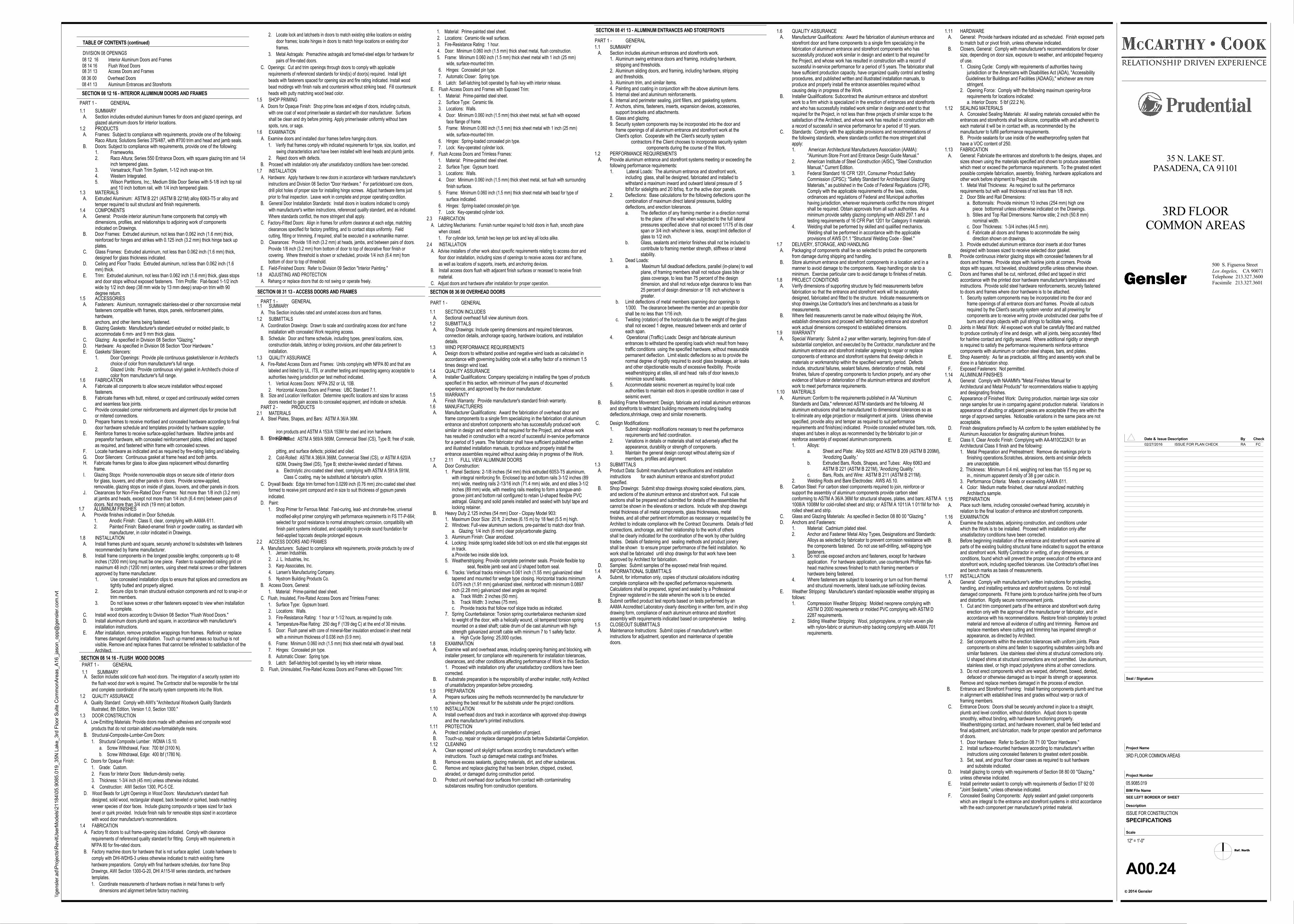
08 14 16 Flush Wood Doors08 31 13 Access Doors and Frames
08 41 13 Aluminum Entrances and Storefronts
TABLE OF CONTENTS (continued)
1. Jensen Industries.2. J. L. Industries, Inc.3. Karp Associates, Inc.4. Larsen's Manufacturing Company.5. Nystrom Building Products Co.
B. Access Doors, General:1. Material: Prime-painted steel sheet.
C. Flush, Insulated, Fire-Rated Access Doors and Trimless Frames:1. Surface Type: Gypsum board.2. Locations: Walls.3. Fire-Resistance Rating: 1 hour or 1-1/2 hours, as required by code.4. Temperature-Rise Rating: 250 deg F (139 deg C) at the end of 30 minutes.5. Door: Flush panel with core of mineral-fiber insulation enclosed in sheet metal
with a minimum thickness of 0.036 inch (0.9 mm).6. Frame: Minimum 0.060 inch (1.5 mm) thick sheet metal with drywall bead.7. Hinges: Concealed pin type.8. Automatic Closer: Spring type.9. Latch: Self-latching bolt operated by key with interior release.
D. Flush, Uninsulated, Fire-Rated Access Doors and Frames with Exposed Trim:
1. Material: Prime-painted steel sheet.2. Locations: Ceramic-tile wall surfaces.3. Fire-Resistance Rating: 1 hour.4. Door: Minimum 0.060 inch (1.5 mm) thick sheet metal, flush construction.5. Frame: Minimum 0.060 inch (1.5 mm) thick sheet metal with 1 inch (25 mm)
wide, surface-mounted trim.6. Hinges: Concealed pin type.7. Automatic Closer: Spring type.8. Latch: Self-latching bolt operated by flush key with interior release.
E. Flush Access Doors and Frames with Exposed Trim:1. Material: Prime-painted steel sheet.2. Surface Type: Ceramic tile.3. Locations: Walls.4. Door: Minimum 0.060 inch (1.5 mm) thick sheet metal, set flush with exposed
face flange of frame.5. Frame: Minimum 0.060 inch (1.5 mm) thick sheet metal with 1 inch (25 mm)
wide, surface-mounted trim.6. Hinges: Spring-loaded concealed pin type.7. Lock: Key-operated cylinder lock.
F. Flush Access Doors and Trimless Frames:1. Material: Prime-painted steel sheet.2. Surface Type: Gypsum board.3. Locations: Walls.4. Door: Minimum 0.060 inch (1.5 mm) thick sheet metal, set flush with surrounding
finish surfaces.5. Frame: Minimum 0.060 inch (1.5 mm) thick sheet metal with bead for type of
surface indicated.6. Hinges: Spring-loaded concealed pin type.7. Lock: Key-operated cylinder lock.
2.3 FABRICATIONA. Latching Mechanisms: Furnish number required to hold doors in flush, smooth plane
when closed.1. For cylinder lock, furnish two keys per lock and key all locks alike.
2.4 INSTALLATIONA. Advise installers of other work about specific requirements relating to access door and
floor door installation, including sizes of openings to receive access door and frame,as well as locations of supports, inserts, and anchoring devices.
B. Install access doors flush with adjacent finish surfaces or recessed to receive finishmaterial.
C. Adjust doors and hardware after installation for proper operation.
SECTION 08 14 16 - FLUSH WOOD DOORS
SECTION 08 36 00 OVERHEAD DOORS
1.1 SECTION INCLUDES A. Sectional overhead full view aluminum doors.1.2 SUBMITTALS A. Shop Drawings: Include opening dimensions and required tolerances,
connection details, anchorage spacing, hardware locations, and installationdetails.
1.3 WIND PERFORMANCE REQUIREMENTS A. Design doors to withstand positive and negative wind loads as calculated in
accordance with governing building code wit a saftey factor of a minimum 1.5times design wind load.
1.4 QUALITY ASSURANCE A. Installer Qualifications: Company specializing in installing the types of products
specified in this section, with minimum of five years of documentedexperience, and approved by the door manufacturer.
1.5 WARRANTY A. Finish Warranty: Provide manufacturer's standard finish warranty.1.6 MANUFACTURERS A. Manufacturer Qualifications: Award the fabrication of overhead door and
frame components to a single firm specializing in the fabrication of aluminumentrance and storefront components who has successfully produced worksimilar in design and extent to that required for the Project, and whose workhas resulted in construction with a record of successful in-service performancefor a period of 5 years. The fabricator shall have sufficient published writtenand illustrated installation manuals, to produce and properly install theentrance assemblies required without ausing delay in progress of the Work.
1.7 2.11 FULL VIEW ALUMINUM DOORS A. Door Construction:
1. Panel Sections: 2-1/8 inches (54 mm) thick extruded 6053-T5 aluminum, with integral reinforcing fin. Enclosed top and bottom rails 3-1/2 inches (89 mm) wide, meeting rails 2-13/16 inch (71.4 mm) wide, and end stiles 3-1/2 inches (89 mm) wide, with meeting rails meeting to form a tongue-and- groove joint and bottom rail configured to retain U-shaped flexible PVC astragal. Glazing and solid panels installed and sealed with butyl tape and locking retainer.
B. Heavy Duty 2.125 inches (54 mm) Door - Clopay Model 903:1. Maximum Door Size: 20 ft, 2 inches (6.15 m) by 18 feet (5.5 m) high.
2. Windows: Full-view aluminum sections, pre-painted to match door finish. a. Glazing: 1/4 inch (6 mm) clear polycarbonate glazing.
3. Aluminum Finish: Clear anodized.4. Locking: Inside spring loaded slide bolt lock on end stile that engages slot in track. a.Provide two inside slide lock.5. Weatherstripping: Provide complete perimeter seals. Provide flexible top
seal, flexible jamb seal and U shaped bottom seal. 6. Tracks: Vertical tracks minimum 0.061 inch (1.55 mm) galvanized steel
tapered and mounted for wedge type closing. Horizontal tracks minimum 0.075 inch (1.91 mm) galvanized steel, reinforced with minimum 0.0897 inch (2.28 mm) galvanized steel angles as required: a. Track Width: 2 inches (50 mm). b. Track Width: 3 inches (75 mm). c. Provide tracks that follow roof slope tracks as indicated.7. Spring Counterbalance: Torsion spring counterbalance mechanism sized to weight of the door, with a helically wound, oil tempered torsion spring mounted on a steel shaft; cable drum of die cast aluminum with high strength galvanized aircraft cable with minimum 7 to 1 safety factor. a. High Cycle Spring: 25,000 cycles.
1.8 EXAMINATION A. Examine wall and overhead areas, including opening framing and blocking, with
installer present, for compliance with requirements for installation tolerances,clearances, and other conditions affecting performance of Work in this Section.1. Proceed with installation only after unsatisfactory conditions have beencorrected.
B. If substrate preparation is the responsibility of another installer, notify Architectof unsatisfactory preparation before proceeding.
1.9 PREPARATION A. Prepare surfaces using the methods recommended by the manufacturer for
achieving the best result for the substrate under the project conditions.1.10 INSTALLATION A. Install overhead doors and track in accordance with approved shop drawings
and the manufacturer's printed instructions.1.11 PROTECTION A. Protect installed products until completion of project. B. Touch-up, repair or replace damaged products before Substantial Completion.1.12 CLEANING A. Clean exposed unit skylight surfaces according to manufacturer's written
instructions. Touch up damaged metal coatings and finishes. B. Remove excess sealants, glazing materials, dirt, and other substances. C. Remove and replace glazing that has been broken, chipped, cracked,
abraded, or damaged during construction period. D. Protect unit overhead door surfaces from contact with contaminating
substances resulting from construction operations.
SECTION 08 41 13 - ALUMINUM ENTRANCES AND STOREFRONTS
1.1 SUMMARY A. Section includes aluminum entrances and storefronts work.
1. Aluminum swing entrance doors and framing, including hardware, stripping and thresholds.2. Aluminum sliding doors, and framing, including hardware, stripping and thresholds.3. Aluminum trim, and similar items.4. Painting and coating in conjunction with the above aluminum items.5. Internal steel and aluminum reinforcements.6. Internal and perimeter sealing, joint fillers, and gasketing systems.7. Anchors, shims, fasteners, inserts, expansion devices, accessories, support brackets and attachments.8. Glass and glazing.9. Security system components may be incorporated into the door and frame openings of all aluminum entrance and storefront work at the Client's option. Cooperate with the Client's security system
contractors if the Client chooses to incorporate security system components during the course of the Work.
1.2 PERFORMANCE REQUIREMENTS A. Provide aluminum entrance and storefront systems meeting or exceeding the
following performance requirements:1. Lateral Loads: The aluminum entrance and storefront work,
including glass, shall be designed, fabricated and installed to withstand a maximum inward and outward lateral pressure of 5 lbf/sf.for sidelights and 20 lbf/sq. ft.or the active door panels.
2. Deflections: Base calculations for the following deflections upon thecombination of maximum direct lateral pressures, building deflections, and erection tolerances.
a. The deflection of any framing member in a direction normalto the plane of the wall when subjected to the full lateral pressures specified above shall not exceed 1/175 of its clearspan or 3/4 inch whichever is less, except limit deflection ofglass to 1/2 inch.
b. Glass, sealants and interior finishes shall not be included tocontribute to framing member strength, stiffness or lateralstability.
3. Dead Loads: a. Maximum full deadload deflections, parallel (in-plane) to wall
plane, of framing members shall not reduce glass bite or glass coverage, to less than 75 percent of the design dimension, and shall not reduce edge clearance to less than25 percent of design dimension or 1/8 inch whichever is greater.
b. Limit deflections of metal members spanning door openings to 1/300. The clearance between the member and an operable doorshall be no less than 1/16 inch.
c. Twisting (rotation) of the horizontals due to the weight of the glassshall not exceed 1 degree, measured between ends and center ofeach span.
4. Operational (Traffic) Loads: Design and fabricate aluminum entrances to withstand the operating loads which result from heavytraffic conditions using the specified hardware, without measurablepermanent deflection. Limit elastic deflections so as to provide thenormal degree of rigidity required to avoid glass breakage, air leaksand other objectionable results of excessive flexibility. Provide weatherstripping at stiles, sill and head rails of door leaves,to minimize sound leaks.
5. Accommodate seismic movement as required by local code authorities to maintain exit doors in operable condition in case of seismic event.
B. Building Frame Movement: Design, fabricate and install aluminum entrancesand storefronts to withstand building movements including loadingdeflections,shrinkage, creep and similar movements.
08 36 00 Overhead Doors
DIVISION 08 OPENINGS
A. Section includes solid core flush wood doors. The integration of a security system intothe flush wood door work is required. The Contractor shall be responsible for the totaland complete coordination of the security system components into the Work.
1.2 QUALITY ASSURANCEA. Quality Standard: Comply with AWI's "Architectural Woodwork Quality Standards
Illustrated, 8th Edition, Version 1.0, Section 1300."1.3 DOOR CONSTRUCTION
A. Low-Emitting Materials: Provide doors made with adhesives and composite woodproducts that do not contain added urea-formaldehyde resins.
B. Structural-Composite-Lumber-Core Doors:1. Structural Composite Lumber: WDMA I.S.10.
a. Screw Withdrawal, Face: 700 lbf (3100 N).b. Screw Withdrawal, Edge: 400 lbf (1780 N).
C. Doors for Opaque Finish:1. Grade: Custom.2. Faces for Interior Doors: Medium-density overlay.3. Thickness: 1-3/4 inch (45 mm) unless otherwise indicated.4. Construction: AWI Section 1300, PC-5 CE.
D. Wood Beads for Light Openings in Wood Doors: Manufacturer's standard flushdesigned, solid wood, rectangular shaped, back beveled or quirked, beads matchingveneer species of door faces. Include glazing compounds or tapes sized for backbevel or quirk provided. Include finish nails for removable stops sized in accordancewith wood door manufacturer's recommendations.
1.4 FABRICATIONA. Factory fit doors to suit frame-opening sizes indicated. Comply with clearance
requirements of referenced quality standard for fitting. Comply with requirements inNFPA 80 for fire-rated doors.
B. Factory machine doors for hardware that is not surface applied. Locate hardware tocomply with DHI-WDHS-3 unless otherwise indicated to match existing framehardware preparations. Comply with final hardware schedules, door frame ShopDrawings, AWI Section 1300-G-20, DHI A115-W series standards, and hardwaretemplates.1. Coordinate measurements of hardware mortises in metal frames to verify
dimensions and alignment before factory machining.
C. Openings: Cut and trim openings through doors to comply with applicablerequirements of referenced standards for kind(s) of door(s) required. Install lightbeads with fasteners spaced for opening size and fire rating indicated. Install woodbead moldings with finish nails and countersink without striking bead. Fill countersunkheads with putty matching wood bead color.
1.5 SHOP PRIMINGA. Doors for Opaque Finish: Shop prime faces and edges of doors, including cutouts,
with one coat of wood primer/sealer as standard with door manufacturer. Surfacesshall be clean and dry before priming. Apply primer/sealer uniformly without barespots, runs, or sags.
1.6 EXAMINATIONA. Examine doors and installed door frames before hanging doors.
1. Verify that frames comply with indicated requirements for type, size, location, andswing characteristics and have been installed with level heads and plumb jambs.
2. Reject doors with defects.B. Proceed with installation only after unsatisfactory conditions have been corrected.
1.7 INSTALLATIONA. Hardware: Apply hardware to new doors in accordance with hardware manufacturer's
instructions and Division 08 Section "Door Hardware." For particleboard core doors,drill pilot holes of proper size for installing hinge screws. Adjust hardware items justprior to final inspection. Leave work in complete and proper operating condition.
B. General Door Installation Standards: Install doors in locations indicated to complywith manufacturer's written instructions, referenced quality standard, and as indicated.Where standards conflict, the more stringent shall apply.
C. Factory-Fitted Doors: Align in frames for uniform clearance at each edge, matchingclearances specified for factory prefitting, and to contact stops uniformly. Fieldcutting, fitting or trimming, if required, shall be executed in a workmanlike manner.
D. Clearances: Provide 1/8 inch (3.2 mm) at heads, jambs, and between pairs of doors.Provide 1/8 inch (3.2 mm) from bottom of door to top of decorative floor finish orcovering. Where threshold is shown or scheduled, provide 1/4 inch (6.4 mm) frombottom of door to top of threshold.
E. Field-Finished Doors: Refer to Division 09 Section "Interior Painting."1.8 ADJUSTING AND PROTECTION
A. Rehang or replace doors that do not swing or operate freely.
SECTION 08 31 13 - ACCESS DOORS AND FRAMES
1.1 SUMMARYA. This Section includes rated and unrated access doors and frames.
1.2 SUBMITTALSA. Coordination Drawings: Drawn to scale and coordinating access door and frame
installation with concealed Work requiring access.B. Schedule: Door and frame schedule, including types, general locations, sizes,
construction details, latching or locking provisions, and other data pertinent toinstallation.
1.3 QUALITY ASSURANCEA. Fire-Rated Access Doors and Frames: Units complying with NFPA 80 and that are
labeled and listed by UL, ITS, or another testing and inspecting agency acceptable toauthorities having jurisdiction per test method indicated.1. Vertical Access Doors: NFPA 252 or UL 10B.2. Horizontal Access Doors and Frames: UBC Standard 7.1.
B. Size and Location Verification: Determine specific locations and sizes for accessdoors needed to gain access to concealed equipment, and indicate on schedule.
2.1 MATERIALSA. Steel Plates, Shapes, and Bars: ASTM A 36/A 36M.
iron products and ASTM A 153/A 153M for steel and iron hardware.B. Steel Sheet:1. Hot-Rolled: ASTM A 569/A 569M, Commercial Steel (CS), Type B; free of scale,
pitting, and surface defects; pickled and oiled.2. Cold-Rolled: ASTM A 366/A 366M, Commercial Steel (CS), or ASTM A 620/A
620M, Drawing Steel (DS), Type B; stretcher-leveled standard of flatness.a. Electrolytic zinc-coated steel sheet, complying with ASTM A 591/A 591M,
Class C coating, may be substituted at fabricator's option.
C. Drywall Beads: Edge trim formed from 0.0299 inch (0.76 mm) zinc-coated steel sheetformed to receive joint compound and in size to suit thickness of gypsum panelsindicated.
D. Paint:1. Shop Primer for Ferrous Metal: Fast-curing, lead- and chromate-free, universal
modified-alkyd primer complying with performance requirements in FS TT-P-664;selected for good resistance to normal atmospheric corrosion, compatibility withfinish paint systems indicated, and capability to provide sound foundation forfield-applied topcoats despite prolonged exposure.
2.2 ACCESS DOORS AND FRAMESA. Manufacturers: Subject to compliance with requirements, provide products by one of
SECTION 08 12 16 - INTERIOR ALUMINUM DOORS AND FRAMES
1.1 SUMMARY A. Section includes extruded aluminum frames for doors and glazed openings, and
glazed aluminum doors for interior locations.1.2 PRODUCTS A. Frames: Subject to compliance with requirements, provide one of the following:
Raco Altura; Solutions Series 375/487, with #700 trim and head and jamb seals. B. Doors: Subject to compliance with requirements, provide one of the following:
1. Frameworks.2. Raco Altura; Series 550 Entrance Doors, with square glazing trim and 1/4
inch tempered glass.3. Versatrack; Flush Trim System, 1-1/2 inch snap-on trim.4. Western Integrated.5. Wilson Partitions, Inc.; Medium Stile Door Series with 5-1/8 inch top rail
and 10 inch bottom rail, with 1/4 inch tempered glass.1.3 MATERIALS A. Extruded Aluminum: ASTM B 221 (ASTM B 221M) alloy 6063-T5 or alloy and
temper required to suit structural and finish requirements.1.4 COMPONENTS A. General: Provide interior aluminum frame components that comply with
dimensions, profiles, and relationships to adjoining work of componentsindicated on Drawings.
B. Door Frames: Extruded aluminum, not less than 0.062 inch (1.6 mm) thick,reinforced for hinges and strikes with 0.125 inch (3.2 mm) thick hinge back upplates.
C. Glass Frames: Extruded aluminum, not less than 0.062 inch (1.6 mm) thick,designed for glass thickness indicated.
D. Ceiling and Floor Tracks: Extruded aluminum, not less than 0.062 inch (1.6mm) thick.
E. Trim: Extruded aluminum, not less than 0.062 inch (1.6 mm) thick, glass stopsand door stops without exposed fasteners. Trim Profile: Flat-faced 1-1/2 inchwide by 1/2 inch deep (38 mm wide by 13 mm deep) snap-on trim with 90degree return.
1.5 ACCESSORIES A. Fasteners: Aluminum, nonmagnetic stainless-steel or other noncorrosive metal
fasteners compatible with frames, stops, panels, reinforcement plates,hardware,anchors, and other items being fastened.
B. Glazing Gaskets: Manufacturer's standard extruded or molded plastic, toaccommodate 6 mm- and 9 mm thick glass.
C. Glazing: As specified in Division 08 Section "Glazing." D. Hardware: As specified in Division 08 Section "Door Hardware." E. Gaskets/ Silencers:
1. Door Openings: Provide pile continuous gasket/silencer in Architect's choice of color from manufacturer's full range.
2. Glazed Units: Provide continuous vinyl gasket in Architect's choice of color from manufacturer's full range.
1.6 FABRICATION A. Fabricate all components to allow secure installation without exposed
fasteners. B. Fabricate frames with butt, mitered, or coped and continuously welded corners
and seamless face joints. C. Provide concealed corner reinforcements and alignment clips for precise butt
or mitered connections. D. Prepare frames to receive mortised and concealed hardware according to final
door hardware schedule and templates provided by hardware supplier. E. Reinforce frames to receive surface-applied hardware. Machine jambs and
preparefor hardware, with concealed reinforcement plates, drilled and tappedas required, and fastened within frame with concealed screws.
F. Locate hardware as indicated and as required by fire-rating listing and labeling. G. Door Silencers: Continuous gasket at frame head and both jambs.
1.8 INSTALLATION A. Install frames plumb and square, securely anchored to substrates with fasteners
recommended by frame manufacturer. B. Install frame components in the longest possible lengths; components up to 48
inches (1200 mm) long must be one piece. Fasten to suspended ceiling grid onmaximum 48 inch (1200 mm) centers, using sheet metal screws or other fastenersapproved by frame manufacturer.1. Use concealed installation clips to ensure that splices and connections are
tightly butted and properly aligned.2. Secure clips to main structural extrusion components and not to snap-in or
trim members.3. Do not leave screws or other fasteners exposed to view when installation
is complete. C. Install wood doors according to Division 08 Section "Flush Wood Doors." D. Install aluminum doors plumb and square, in accordance with manufacturer's
installation instructions. E. After installation, remove protective wrappings from frames. Refinish or replace
frames damaged during installation. Touch up marred areas so touchup is not visible. Remove and replace frames that cannot be refinished to satisfaction of theArchitect.
1.7 ALUMINUM FINISHES A. Provide finishes indicated in Door Schedule.
1. Anodic Finish: Class II, clear, complying with AAMA 611.2. Painted Finish: Baked-enamel finish or powder coating, as standard with manufacturer, in color indicated in Drawings.
H. Fabricate frames for glass to allow glass replacement without dismantlingframe.
I. Glazing Stops: Provide nonremovable stops on secure side of interior doorsfor glass, louvers, and other panels in doors. Provide screw-applied,removable, glazing stops on inside of glass, louvers, and other panels in doors.
J. Clearances for Non-Fire-Rated Door Frames: Not more than 1/8 inch (3.2 mm)at jambs and heads, except not more than 1/4 inch (6.4 mm) between pairs ofdoors. Not more than 3/4 inch (19 mm) at bottom.
08 12 16 Interior Aluminum Doors and Frames
PART 1 - GENERAL
PART 1 - GENERAL
PART 2 - PRODUCTS
1.9 WARRANTY A. Special Warranty: Submit a 2 year written warranty, beginning from date of
substantial completion, and executed by the Contractor, manufacturer and thealuminum entrance and storefront installer agreeing to repair or replacecomponents of entrance and storefront systems that develop defects inmaterials or workmanship within the specified warranty period. Defectsinclude, structural failures, sealant failures, deterioration of metals, metalfinishes, failure of operating components to function properly, and any otherevidence of failure or deterioration of the aluminum entrance and storefrontwork to meet performance requirements.
1.10 MATERIALS A. Aluminum: Conform to the requirements published in AA "Aluminum
Standards and Data," referenced ASTM standards and the following. Allaluminum extrusions shall be manufactured to dimensional tolerances so asto eliminate any edge projection or misalignment at joints. Unless otherwisespecified, provide alloy and temper as required to suit performancerequirements and finish(es) indicated. Provide concealed extruded bars, rods,shapes and tubes in alloys as recommended by the fabricator to join orreinforce assembly of exposed aluminum components.1. Alloys: a. Sheet and Plate: Alloy 5005 and ASTM B 209 (ASTM B 209M),
'Anodizing Quality.' b. Extruded Bars, Rods, Shapes, and Tubes: Alloy 6063 and
ASTM B 221 (ASTM B 221M), 'Anodizing Quality.' c. Bars, Rods, and Wire: ASTM B 211 (ASTM B 211M).
2. Welding Rods and Bare Electrodes: AWS A5.10. B. Carbon Steel: For carbon steel components required to join, reinforce or
support the assembly of aluminum components provide carbon steelconforming to ASTM A 36/A 36M for structural shapes, plates, and bars; ASTM A1008/A 1008M for cold-rolled sheet and strip; or ASTM A 1011/A 1 011M for hot-rolled sheet and strip.
C. Glass and Glazing Materials: As specified in Section 08 80 00 "Glazing." D. Anchors and Fasteners:
1. Material: Cadmium plated steel.2. Anchor and Fastener Metal Alloy Types, Designations and Standards:
Alloys as selected by fabricator to prevent corrosion resistance withthe components fastened. Do not use self-drilling, self-tapping typefasteners.
1.6 QUALITY ASSURANCE A. Manufacturer Qualifications: Award the fabrication of aluminum entrance and
storefront door and frame components to a single firm specializing in thefabrication of aluminum entrance and storefront components who hassuccessfully produced work similar in design and extent to that required forthe Project, and whose work has resulted in construction with a record ofsuccessful in-service performance for a period of 5 years. The fabricator shallhave sufficient production capacity, have organized quality control and testingprocedures, and published written and illustrated installation manuals, toproduce and properly install the entrance assemblies required withoutcausing delay in progress of the Work.
B. Installer Qualifications: Subcontract the aluminum entrance and storefrontwork to a firm which is specialized in the erection of entrances and storefrontsand who has successfully installed work similar in design and extent to thatrequired for the Project, in not less than three projects of similar scope to thesatisfaction of the Architect, and whose work has resulted in construction witha record of successful in service performance for a period of 10 years.
C. Standards: Comply with the applicable provisions and recommendations ofthe following standards, where standards conflict the more stringent shallapply:1. American Architectural Manufacturers Association (AAMA):
"Aluminum Store Front and Entrance Design Guide Manual."2. American Institute of Steel Construction (AISC), "Steel Construction
Manual," Current Edition.3. Federal Standard 16 CFR 1201, Consumer Product Safety
Commission (CPSC): "Safety Standard for Architectural Glazing Materials," as published in the Code of Federal Regulations (CFR).Comply with the applicable requirements of the laws, codes, ordinances and regulations of Federal and Municipal authorities having jurisdiction, wherever requirements conflict the more stringentshall be required. Obtain approvals from all such authorities. As aminimum provide safety glazing complying with ANSI Z97.1 and testing requirements of 16 CFR Part 1201 for Category II materials.
4. Welding shall be performed by skilled and qualified mechanics. Welding shall be performed in accordance with the applicable provisions of AWS D1.1 "Structural Welding Code - Steel."
1.7 DELIVERY, STORAGE, AND HANDLING A. Packaging of components shall be so selected to protect the components
from damage during shipping and handling. B. Store aluminum entrance and storefront components in a location and in a
manner to avoid damage to the components. Keep handling on site to aminimum. Exercise particular care to avoid damage to finishes of metals.
1.8 PROJECT CONDITIONS A. Verify dimensions of supporting structure by field measurements before
fabrication so that the entrance and storefront work will be accuratelydesigned, fabricated and fitted to the structure. Indicate measurements onshop drawings.Use Contractor's lines and benchmarks as a basis formeasurements.
B. Where field measurements cannot be made without delaying the Work,establish dimensions and proceed with fabricating entrance and storefrontwork actual dimensions correspond to established dimensions.
C. Design Modifications:1. Submit design modifications necessary to meet the performance
requirements and field coordination.2. Variations in details or materials shall not adversely affect the
appearance, durability or strength of components.3. Maintain the general design concept without altering size of
members, profiles and alignment.1.3 SUBMITTALS A. Product Data: Submit manufacturer's specifications and installation
instructions for each aluminum entrance and storefront productspecified.
B. Shop Drawings: Submit shop drawings showing scaled elevations, plans,and sections of the aluminum entrance and storefront work. Full scalesections shall be prepared and submitted for details of the assemblies thatcannot be shown in the elevations or sections. Include with shop drawingsmetal thickness of all metal components, glass thicknesses, metalfinishes, and all other pertinent information as necessary or requested by theArchitect to indicate compliance with the Contract Documents. Details of fieldconnections, anchorage, and their relationship to the work of othersshall be clearly indicated for the coordination of the work by other buildingtrades. Details of fastening and sealing methods and product joineryshall be shown to ensure proper performance of the field installation. Nowork shall be fabricated until shop drawings for that work have beenapproved by Architect for fabrication.
D. Samples: Submit samples of the exposed metal finish required.1.4 INFORMATIONAL SUBMITTALS A. Submit, for information only, copies of structural calculations indicating
complete compliance with the specified performance requirements.Calculations shall be prepared, signed and sealed by a ProfessionalEngineer registered in the state wherein the work is to be erected.
B. Submit certified product test reports based on tests performed by anAAMA Accredited Laboratory clearly describing in written form, and in shopdrawing form, compliance of each aluminum entrance and storefrontassembly with requirements indicated based on comprehensive testing.
1.5 CLOSEOUT SUBMITTALS A. Maintenance Instructions: Submit copies of manufacturer's written
instructions for adjustment, operation and maintenance of operabledoors.
damaged components. Fit frame joints to produce hairline joints free of burrsand distortion. Rigidly secure nonmovement joints.1. Cut and trim component parts of the entrance and storefront work during erection only with the approval of the manufacturer or fabricator, and in accordance with his recommendations. Restore finish completely to protect material and remove all evidence of cutting and trimming. Remove and replace members where cutting and trimming has impaired strength or appearance, as directed by Architect.2. Set components within the erection tolerances with uniform joints. Place components on shims and fasten to supporting substrates using bolts and similar fasteners. Use stainless steel shims at structural connections only. U shaped shims at structural connections are not permitted. Use aluminum, stainless steel, or high impact polystyrene shims at other connections.3. Do not erect components which are warped, deformed, bowed, dented, defaced or otherwise damaged as to impair its strength or appearance.Remove and replace members damaged in the process of erection.
B. Entrance and Storefront Framing: Install framing components plumb and truein alignment with established lines and grades without warp or rack offraming members.
C. Entrance Doors: Doors shall be securely anchored in place to a straight,plumb and level condition, without distortion. Adjust doors to operatesmoothly, without binding, with hardware functioning properly.Weatherstripping contact, and hardware movement, shall be field tested andfinal adjustment, and lubrication, made for proper operation and performanceof doors.1. Door Hardware: Refer to Section 08 71 00 "Door Hardware."2. Install surface-mounted hardware according to manufacturer's written instructions using concealed fasteners to greatest extent possible.3. Set, seal, and grout floor closer cases as required to suit hardware and substrate indicated.
D. Install glazing to comply with requirements of Section 08 80 00 "Glazing,"unless otherwise indicated.
E. Install perimeter sealant to comply with requirements of Section 07 92 00"Joint Sealants," unless otherwise indicated.
F. Concealed Sealing Components: Apply sealant and gasket componentswhich are integral to the entrance and storefront systems in strict accordancewith the each component per manufacturer's printed material.
1.11 HARDWARE A. General: Provide hardware indicated and as scheduled. Finish exposed parts
to match butt or pivot finish, unless otherwise indicated. B. Closers, General: Comply with manufacturer's recommendations for closer
size, depending on door size, exposure to weather, and anticipated frequencyof use.1. Closing Cycle: Comply with requirements of authorities having jurisdiction or the Americans with Disabilities Act (ADA), "Accessibility Guidelines for Buildings and Facilities (ADAAG)," whichever are more stringent.2. Opening Force: Comply with the following maximum opening-force requirements for locations indicated: a. Interior Doors: 5 lbf (22.2 N).
1.12 SEALING MATERIALSA. Concealed Sealing Materials: All sealing materials concealed within theentrances and storefronts shall be silicone, compatible with and adherent toeach material it will be in contact with, as recommended by themanufacturer to fulfill performance requirements.B. Provide sealants for use inside of the weatherproofing system that have a VOC content of 250.
1.13 FABRICATION A. General: Fabricate the entrances and storefronts to the designs, shapes, and
sizes shown using the materials specified and shown to produce assemblieswhich meet or exceed the performance requirements. To the greatest extentpossible complete fabrication, assembly, finishing, hardware applications andother work before shipment to Project site.1. Metal Wall Thickness: As required to suit the performance requirements but with wall thickness of not less than 1/8 inch.2. Door Stile and Rail Dimensions: a. Bottomrails: Provide minimum 10 inches (254 mm) high one piece bottomrail unless otherwise indicated on the Drawings. b. Stiles and Top Rail Dimensions: Narrow stile; 2 inch (50.8 mm) nominal width. c. Door Thickness: 1-3/4 inches (44.5 mm). d. Fabricate all doors and frames to accommodate the swing direction shown on drawings.3. Provide extruded aluminum entrance door inserts at door frames designed with bosses sized to receive selected door gasket.
B. Provide continuous interior glazing stops with concealed fasteners for alldoors and frames. Provide stops with hairline joints at corners. Providestops with square, not beveled, shouldered profile unless otherwise shown.
C. Doors and frames shall be cut, reinforced, drilled and tapped in strictaccordance with the printed door hardware manufacturer's templates andinstructions. Provide solid steel hardware reinforcements, securely fastenedto doors and frames where door hardware is to be attached.1. Security system components may be incorporated into the door and frame openings of all entrance doors and frames. Provide all cutouts required by the Client's security system vendor and all prewiring for components are to receive wiring provide unobstructed clear paths free of burrs and sharp objects with pull strings to facilitate wiring.
D. Joints in Metal Work: All exposed work shall be carefully fitted and matchedto produce continuity of line and design, with all joints, being accurately fittedfor hairline contact and rigidly secured. Where additional rigidity or strengthis required to satisfy the performance requirements reinforce entrancecomponents with aluminum or carbon steel shapes, bars, and plates.
E. Shop Assembly: As far as practicable, all fitting and assembly work shall bedone in a fabrication shop.
F. Exposed Fasteners: Not permitted.1.14 ALUMINUM FINISHES A. General: Comply with NAAMM's "Metal Finishes Manual for
Architectural and Metal Products" for recommendations relative to applyingand designating finishes.
C. Appearance of Finished Work: During production, maintain large size colorrange samples for use in comparing against production material. Variations inappearance of abutting or adjacent pieces are acceptable if they are within therange of approved samples. Noticeable variations in the same piece are notacceptable.
D. Finish designations prefixed by AA conform to the system established by theAluminum Association for designating aluminum finishes.
E. Class II, Clear Anodic Finish: Complying with AA-M10C22A31 for anArchitectural Class II finish and the following:1. Metal Preparation and Pretreatment: Remove die markings prior to finishing operations.Scratches, abrasions, dents and similar defects are unacceptable.2. Thickness: Minimum 0.4 mil, weighing not less than 15.5 mg per sq. in., minimum apparent density of 38 g per cubic in.3. Performance Criteria: Meets or exceeding AAMA 611.4. Color: Medium matte finished, clear natural anodized matching Architect's sample.
1.15 PREPARATION A. Place such items, including concealed overhead framing, accurately in
relation to the final location of entrance and storefront components.1.16 EXAMINATION A. Examine the substrates, adjoining construction, and conditions under
which the Work is to be installed. Proceed with installation only afterunsatisfactory conditions have been corrected.
B. Before beginning installation of the entrance and storefront work examine allparts of the existing building structural frame indicated to support the entranceand storefront work. Notify Contractor in writing, of any dimensions, orconditions, found which will prevent the proper execution of the entrance andstorefront work, including specified tolerances. Use Contractor's offset linesand bench marks as basis of measurements.
1.17 INSTALLATION A. General: Comply with manufacturer's written instructions for protecting,
handling, and installing entrance and storefront systems. Do not install
3. Do not use exposed anchors and fasteners, except for hardware application. For hardware application, use countersunk Phillips flat-head machine screws finished to match framing members or hardware being fastened.
4. Where fasteners are subject to loosening or turn out from thermaland structural movements, lateral loads,use self-locking devices.
E. Weather Stripping: Manufacturer's standard replaceable weather stripping asfollows:1. Compression Weather Stripping: Molded neoprene complying with
ASTM D 2000 requirements or molded PVC complying with ASTM D2287 requirements.
2. Sliding Weather Stripping: Wool, polypropylene, or nylon woven pilewith nylon-fabric or aluminum-strip backing complying with AAMA 701requirements.
2. Locate lock and latchsets in doors to match existing strike locations on existingdoor frames; locate hinges in doors to match hinge locations on existing doorframes.
3. Metal Astragals: Premachine astragals and formed-steel edges for hardware forpairs of fire-rated doors.
PART 1 - GENERAL
1.1 SUMMARY
PART 1 - GENERAL
PART 1 - GENERAL
Ref. North
CA 90071Los Angeles,
2014 Gensler
Project Number
BIM File Name
Scale
Description
c
Project Name
Seal / Signature
Check
Facsimile 213.327.3601
Telephone 213.327.3600
Date & By
500 S. Figueroa Street
Issue Description
SEE LEFT BORDER OF SHEET
\\ge
nsl
er.
ad\P
roje
cts
\RevitU
serM
od
els
\21
184
\05
.90
85.0
19
_35
N L
ake
_3rd
Flo
or
Su
ite C
om
mo
nA
reas_A
16_ja
son_o
pp@
gen
sle
r.com
.rvt
12" = 1'-0"
35 N. LAKE ST.PASADENA, CA 91101
3RD FLOORCOMMON AREAS
3RD FLOOR COMMON AREAS
05.9085.019
ISSUE FOR CONSTRUCTION
A00.24
SPECIFICATIONS
02/27/2016 ISSUE FOR PLAN CHECK RA FC
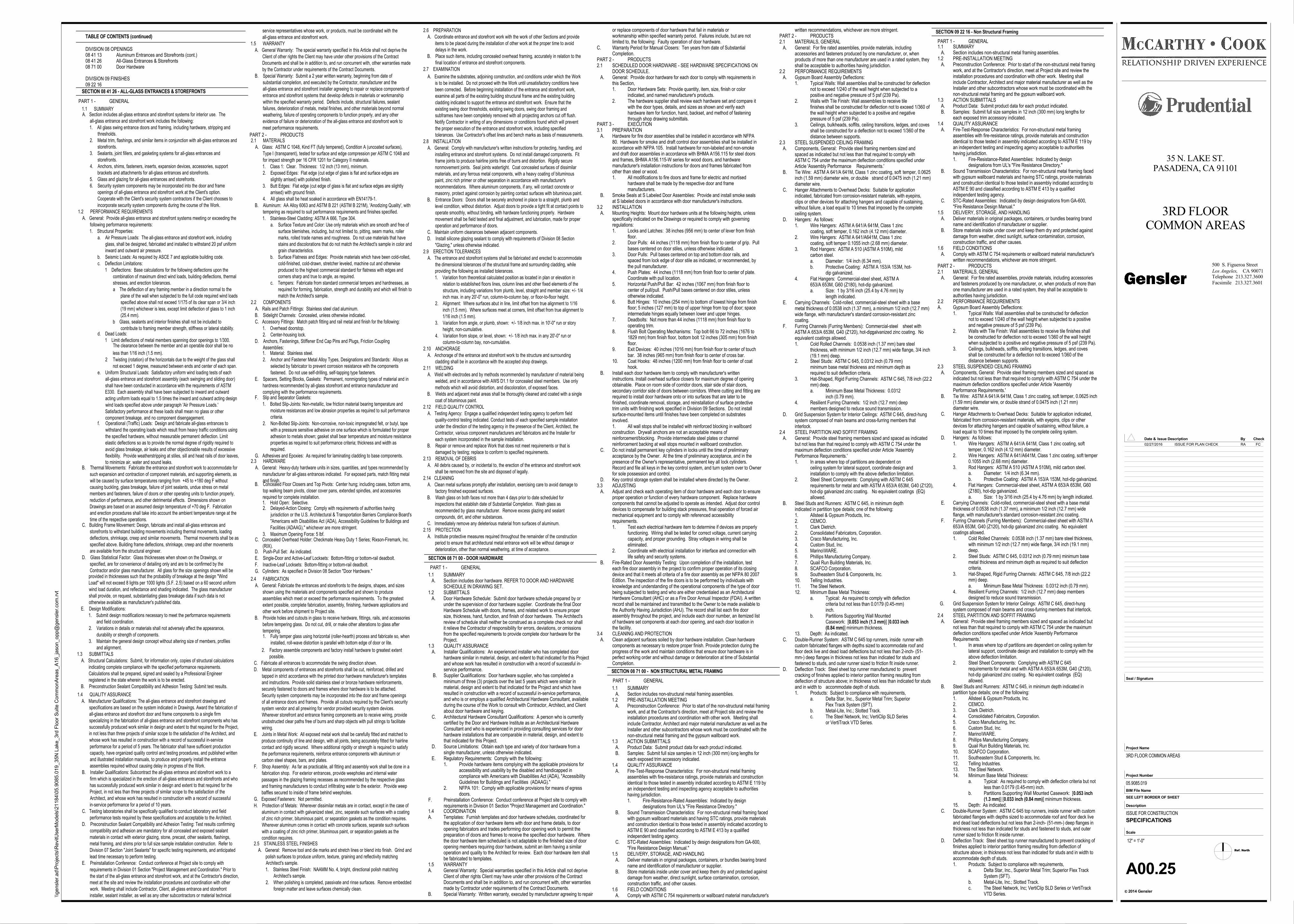
TABLE OF CONTENTS (continued)
DIVISION 08 OPENINGS08 41 13 Aluminum Entrances and Storefronts (cont.)08 41 26 All-Glass Entrances & Storefronts08 71 00 Door Hardware
DIVISION 09 FINISHES09 22 16
performance for a period of 5 years. The fabricator shall have sufficient productioncapacity, have organized quality control and testing procedures, and published writtenand illustrated installation manuals, to produce and properly install the entranceassemblies required without causing delay in progress of the Work.
B. Installer Qualifications: Subcontract the all-glass entrance and storefront work to afirm which is specialized in the erection of all-glass entrances and storefronts and whohas successfully produced work similar in design and extent to that required for theProject, in not less than three projects of similar scope to the satisfaction of theArchitect, and whose work has resulted in construction with a record of successfulin-service performance for a period of 10 years.
C. Testing laboratories shall be specifically qualified to conduct laboratory and fieldperformance tests required by these specifications and acceptable to the Architect.
D. Preconstruction Sealant Compatibility and Adhesion Testing: Test results confirmingcompatibility and adhesion are mandatory for all concealed and exposed sealantmaterials in contact with exterior glazing, stone, precast, other sealants, flashings,metal framing, and shims prior to full size sample installation construction. Refer toDivision 07 Section "Joint Sealants" for specific testing requirements, and anticipatedlead time necessary to perform testing.
E. Preinstallation Conference: Conduct conference at Project site to comply withrequirements in Division 01 Section "Project Management and Coordination." Prior tothe start of the all-glass entrance and storefront work, and at the Contractor's direction,meet at the site and review the installation procedures and coordination with otherwork. Meeting shall include Contractor, Client, all-glass entrance and storefrontinstaller, sealant installer, as well as any other subcontractors or material technical
service representatives whose work, or products, must be coordinated with theall-glass entrance and storefront work.
1.5 WARRANTYA. General Warranty: The special warranty specified in this Article shall not deprive the
Client of other rights the Client may have under other provisions of the ContractDocuments and shall be in addition to, and run concurrent with, other warranties madeby the Contractor under requirements of the Contract Documents.
B. Special Warranty: Submit a 2 year written warranty, beginning from date ofsubstantial completion, and executed by the Contractor, manufacturer and theall-glass entrance and storefront installer agreeing to repair or replace components ofentrance and storefront systems that develop defects in materials or workmanshipwithin the specified warranty period. Defects include, structural failures, sealantfailures, deterioration of metals, metal finishes, and other materials beyond normalweathering, failure of operating components to function properly, and any otherevidence of failure or deterioration of the all-glass entrance and storefront work tomeet performance requirements.
2.1 MATERIALSA. Glass: ASTM C 1048, Kind FT (fully tempered), Condition A (uncoated surfaces),
Type I (transparent), tested for surface and edge compression per ASTM C 1048 andfor impact strength per 16 CFR 1201 for Category II materials.1. Class 1: Clear. Thickness: 1/2 inch (13 mm), minimum.2. Exposed Edges: Flat edge (cut edge of glass is flat and surface edges are
slightly arrised) with polished finish.3. Butt Edges: Flat edge (cut edge of glass is flat and surface edges are slightly
arrised) with ground finish.4. All glass shall be heat soaked in accordance with EN14179-1.
B. Aluminum: AA Alloy 6063 and ASTM B 221 (ASTM B 221M), 'Anodizing Quality', withtempering as required to suit performance requirements and finishes specified.1. Stainless-Steel Cladding: ASTM A 666, Type 304.
a. Surface Texture and Color: Use only materials which are smooth and free ofsurface blemishes, including, but not limited to, pitting, seam marks, rollermarks, rolled trade names and roughness. Do not use materials that havestains and discolorations that do not match the Architect's sample in color andgrain characteristics.
b. Surface Flatness and Edges: Provide materials which have been cold-rolled,cold-finished, cold-drawn, stretcher leveled, machine cut and otherwiseproduced to the highest commercial standard for flatness with edges andcorners sharp and true to angle, as required.
c. Tempers: Fabricate from standard commercial tempers and hardnesses, asrequired for forming, fabrication, strength and durability and which will finish tomatch the Architect's sample.
2.2 COMPONENTSA. Rails and Patch Fittings: Stainless steel clad aluminum.B. Sidelight Channels: Concealed, unless otherwise indicated.C. Accessory Fittings: Match patch fitting and rail metal and finish for the following:
1. Overhead doorstop.2. Center-housing lock.
D. Anchors, Fastenings, Stiffener End Cap Pins and Plugs, Friction CouplingAssemblies:1. Material: Stainless steel.2. Anchor and Fastener Metal Alloy Types, Designations and Standards: Alloys as
selected by fabricator to prevent corrosion resistance with the componentsfastened. Do not use self-drilling, self-tapping type fasteners.
E. Spacers, Setting Blocks, Gaskets: Permanent, nonmigrating types of material and inhardness recommended by all-glass storefront and entrance manufacturer andcomplying with the performance requirements.
F. Slip and Separator Gaskets:1. Bolted Slip-Joints: Non-metallic, low friction material bearing temperature and
moisture resistances and low abrasion properties as required to suit performancecriteria.
2. Non-Bolted Slip-Joints: Non-corrosive, non-toxic impregnated felt, or butyl, tapewith a pressure sensitive adhesive on one surface which is formulated for properadhesion to metals shown; gasket shall bear temperature and moisture resistanceproperties as required to suit performance criteria; thickness and width asrequired.
G. Adhesives and Epoxies: As required for laminating cladding to base components.2.3 HARDWARE
A. General: Heavy-duty hardware units in sizes, quantities, and types recommended bymanufacturer for all-glass entrances indicated. For exposed parts, match fitting metaland finish.
B. Concealed Floor Closers and Top Pivots: Center hung; including cases, bottom arms,top walking beam pivots, closer cover pans, extended spindles, and accessoriesrequired for complete installation.1. Hold Open: Selective.2. Delayed-Action Closing: Comply with requirements of authorities having
jurisdiction or the U.S. Architectural & Transportation Barriers Compliance Board's"Americans with Disabilities Act (ADA), Accessibility Guidelines for Buildings andFacilities (ADAAG)," whichever are more stringent.
3. Maximum Opening Force: 5 lbf.C. Concealed Overhead Holder: Checkmate Heavy Duty 1 Series; Rixson-Firemark, Inc.
(RIX).D. Push-Pull Set: As indicated.E. Single-Door and Active-Leaf Locksets: Bottom-fitting or bottom-rail deadbolt.F. Inactive-Leaf Locksets: Bottom-fitting or bottom-rail deadbolt.G. Cylinders: As specified in Division 08 Section "Door Hardware."
2.4 FABRICATIONA. General: Fabricate the entrances and storefronts to the designs, shapes, and sizes
shown using the materials and components specified and shown to produceassemblies which meet or exceed the performance requirements. To the greatestextent possible, complete fabrication, assembly, finishing, hardware applications andother work before shipment to Project site.
B. Provide holes and cutouts in glass to receive hardware, fittings, rails, and accessoriesbefore tempering glass. Do not cut, drill, or make other alterations to glass aftertempering.1. Fully temper glass using horizontal (roller-hearth) process and fabricate so, when
installed, roll-wave distortion is parallel with bottom edge of door or lite.
2. Factory assemble components and factory install hardware to greatest extentpossible.
C. Fabricate all entrances to accommodate the swing direction shown.D. Metal components of entrances and storefronts shall be cut, reinforced, drilled and
tapped in strict accordance with the printed door hardware manufacturer's templatesand instructions. Provide solid stainless steel or bronze hardware reinforcements,securely fastened to doors and frames where door hardware is to be attached.Security system components may be incorporated into the door and frame openingsof all entrance doors and frames. Provide all cutouts required by the Client's securitysystem vendor and all prewiring for vendor provided security system devices.Wherever storefront and entrance framing components are to receive wiring, provideunobstructed clear paths free of burrs and sharp objects with pull strings to facilitatewiring.
E. Joints in Metal Work: All exposed metal work shall be carefully fitted and matched toproduce continuity of line and design, with all joints, being accurately fitted for hairlinecontact and rigidly secured. Where additional rigidity or strength is required to satisfythe performance requirements, reinforce entrance components with aluminum orcarbon steel shapes, bars, and plates.
F. Shop Assembly: As far as practicable, all fitting and assembly work shall be done in afabrication shop. For exterior entrances, provide weepholes and internal waterpassages in the glazing framing recesses as recommended by the respective glassand framing manufacturers to conduct infiltrating water to the exterior. Provide weepbaffles secured to inside of frame behind weepholes.
G. Exposed Fasteners: Not permitted.H. Protection of Metals: Wherever dissimilar metals are in contact, except in the case of
aluminum in contact with galvanized steel, zinc, separate such surfaces with a coatingof zinc rich primer, bituminous paint, or separation gaskets as the condition requires.Wherever aluminum comes in contact with concrete surfaces, separate such surfaceswith a coating of zinc rich primer, bituminous paint, or separation gaskets as thecondition requires.
2.5 STAINLESS STEEL FINISHESA. General: Remove tool and die marks and stretch lines or blend into finish. Grind and
polish surfaces to produce uniform, texture, graining and reflectivity matchingArchitect's sample.1. Stainless Steel Finish: NAAMM No. 4, bright, directional polish matching
Architect's sample.2. When polishing is completed, passivate and rinse surfaces. Remove embedded
foreign matter and leave surfaces chemically clean.
2.6 PREPARATIONA. Coordinate entrance and storefront work with the work of other Sections and provide
items to be placed during the installation of other work at the proper time to avoiddelays in the work.
B. Place such items, including concealed overhead framing, accurately in relation to thefinal location of entrance and storefront components.
2.7 EXAMINATION
A. Examine the substrates, adjoining construction, and conditions under which the Workis to be installed. Do not proceed with the Work until unsatisfactory conditions havebeen corrected. Before beginning installation of the entrance and storefront work,examine all parts of the existing building structural frame and the existing buildingcladding indicated to support the entrance and storefront work. Ensure that theexisting swing door thresholds, existing swing doors, swing door framing andsubframes have been completely removed with all projecting anchors cut off flush.Notify Contractor in writing of any dimensions or conditions found which will preventthe proper execution of the entrance and storefront work, including specifiedtolerances. Use Contractor's offset lines and bench marks as basis of measurements.
2.8 INSTALLATIONA. General: Comply with manufacturer's written instructions for protecting, handling, and
installing entrance and storefront systems. Do not install damaged components. Fitframe joints to produce hairline joints free of burrs and distortion. Rigidly securenonmovement joints. Seal joints watertight. Coat concealed surfaces of dissimilarmaterials, and any ferrous metal components, with a heavy coating of bituminouspaint, zinc rich primer or other separation in accordance with manufacturer'srecommendations. Where aluminum components, if any, will contact concrete ormasonry, protect against corrosion by painting contact surfaces with bituminous paint.
B. Entrance Doors: Doors shall be securely anchored in place to a straight, plumb andlevel condition, without distortion. Adjust doors to provide a tight fit at contact points tooperate smoothly, without binding, with hardware functioning properly. Hardwaremovement shall be field tested and final adjustment, and lubrication, made for properoperation and performance of doors.
C. Maintain uniform clearances between adjacent components.D. Install silicone glazing sealant to comply with requirements of Division 08 Section
"Glazing," unless otherwise indicated.2.9 ERECTION TOLERANCES
A. The entrance and storefront systems shall be fabricated and erected to accommodatethe dimensional tolerances of the structural frame and surrounding cladding, whileproviding the following as installed tolerances.1. Variation from theoretical calculated position as located in plan or elevation in
relation to established floors lines, column lines and other fixed elements of thestructure, including variations from plumb, level, straight and member size: +/- 1/4inch max. in any 20'-0" run, column-to-column bay, or floor-to-floor height.
2. Alignment: Where surfaces abut in line, limit offset from true alignment to 1/16inch (1.5 mm). Where surfaces meet at corners, limit offset from true alignment to1/16 inch (1.5 mm).
3. Variation from angle, or plumb, shown: +/- 1/8 inch max. in 10'-0" run or storyheight, non-cumulative.
4. Variation from slope, or level, shown: +/- 1/8 inch max. in any 20'-0" run orcolumn-to-column bay, non-cumulative.
2.10 ANCHORAGEA. Anchorage of the entrance and storefront work to the structure and surrounding
cladding shall be in accordance with the accepted shop drawings.2.11 WELDING
A. Weld with electrodes and by methods recommended by manufacturer of material beingwelded, and in accordance with AWS D1.1 for concealed steel members. Use onlymethods which will avoid distortion, and discoloration, of exposed faces.
B. Welds and adjacent metal areas shall be thoroughly cleaned and coated with a singlecoat of bituminous paint.
2.12 FIELD QUALITY CONTROLA. Testing Agency: Engage a qualified independent testing agency to perform field
quality-control testing indicated. Conduct tests of each specified sample installationunder the direction of the testing agency in the presence of the Client, Architect, theContractor, various component manufacturers and fabricators and the Installer foreach system incorporated in the sample installation.
B. Repair or remove and replace Work that does not meet requirements or that isdamaged by testing; replace to conform to specified requirements.
2.13 REMOVAL OF DEBRISA. All debris caused by, or incidental to, the erection of the entrance and storefront work
shall be removed from the site and disposed of legally.2.14 CLEANING
A. Clean metal surfaces promptly after installation, exercising care to avoid damage tofactory finished exposed surfaces.
B. Wash glass on both faces not more than 4 days prior to date scheduled forinspections that establish date of Substantial Completion. Wash glass asrecommended by glass manufacturer. Remove excess glazing and sealantcompounds, dirt, and other substances.
C. Immediately remove any deleterious material from surfaces of aluminum.2.15 PROTECTION
A. Institute protective measures required throughout the remainder of the constructionperiod to ensure that architectural metal entrance work will be without damage ordeterioration, other than normal weathering, at time of acceptance.
SECTION 08 71 00 - DOOR HARDWARE
1.1 SUMMARY A. Section includes door hardware. REFER TO DOOR AND HARDWARE
SCHEDULE IN DRAWING SET.1.2 SUBMITTALS A. Door Hardware Schedule: Submit door hardware schedule prepared by or
under the supervision of door hardware supplier. Coordinate the final DoorHardware Schedule with doors, frames, and related work to ensure propersize, thickness, hand, function, and finish of door hardware. The Architect'sreview of schedule shall neither be construed as a complete check nor shallit relieve the Contractor of responsibility for errors, deviations, or omissionsfrom the specified requirements to provide complete door hardware for theProject.
1.3 QUALITY ASSURANCE A. Installer Qualifications: An experienced installer who has completed door
hardware similar in material, design, and extent to that indicated for this Projectand whose work has resulted in construction with a record of successful in-service performance.
B. Supplier Qualifications: Door hardware supplier, who has completed aminimum of three (3) projects over the last 5 years which were similar inmaterial, design and extent to that indicated for the Project and which haveresulted in construction with a record of successful in-service performance,and who is or employs a qualified Architectural Hardware Consultant, availableduring the course of the Work to consult with Contractor, Architect, and Clientabout door hardware and keying.
C. Architectural Hardware Consultant Qualifications: A person who is currentlycertified by the Door and Hardware Institute as an Architectural HardwareConsultant and who is experienced in providing consulting services for doorhardware installations that are comparable in material, design, and extent tothat indicated for this Project.
D. Source Limitations: Obtain each type and variety of door hardware from asingle manufacturer, unless otherwise indicated.
E. Regulatory Requirements: Comply with the following:1. Provide hardware items complying with the applicable provisions for
accessibility and usability by the disabled and handicapped in compliance with Americans with Disabilities Act (ADA), "AccessibilityGuidelines for Buildings and Facilities (ADAAG)."
2. NFPA 101: Comply with applicable provisions for means of egressdoors.
F. Preinstallation Conference: Conduct conference at Project site to comply withrequirements in Division 01 Section "Project Management and Coordination."
1.4 COORDINATIONA. Templates: Furnish templates and door hardware schedules, coordinated for
the application of door hardware items with door and frame details, to dooropening fabricators and trades performing door opening work to permit thepreparation of doors and frames to receive the specified door hardware. Wherethe door hardware item scheduled is not adaptable to the finished size of dooropening members requiring door hardware, submit an item having a similaroperation and quality to the Architect for review. Each door hardware item shallbe fabricated to templates.
1.5 WARRANTYA. General Warranty: Special warranties specified in this Article shall not deprive
Client of other rights Client may have under other provisions of the ContractDocuments and shall be in addition to, and run concurrent with, other warrantiesmade by Contractor under requirements of the Contract Documents.
B. Special Warranty: Written warranty, executed by manufacturer agreeing to repair
SECTION 08 41 26 - ALL-GLASS ENTRANCES & STOREFRONTS
1.1 SUMMARYA. Section includes all-glass entrance and storefront systems for interior use. The
all-glass entrance and storefront work includes the following:1. All glass swing entrance doors and framing, including hardware, stripping and
thresholds.2. Metal trim, flashings, and similar items in conjunction with all-glass entrances and
storefronts.3. Sealants, joint fillers, and gasketing systems for all-glass entrances and
storefronts.4. Anchors, shims, fasteners, inserts, expansion devices, accessories, support
brackets and attachments for all-glass entrances and storefronts.5. Glass and glazing for all-glass entrances and storefronts.6. Security system components may be incorporated into the door and frame
openings of all-glass entrance and storefront work at the Client's option.Cooperate with the Client's security system contractors if the Client chooses toincorporate security system components during the course of the Work.
1.2 PERFORMANCE REQUIREMENTSA. General: Provide all-glass entrance and storefront systems meeting or exceeding the
following performance requirements:1. Structural Properties:
a. Air Pressure Loads: The all-glass entrance and storefront work, includingglass, shall be designed, fabricated and installed to withstand 20 psf uniforminward and outward air pressure.
b. Seismic Loads: As required by ASCE 7 and applicable building code.c. Deflection Limitations:
1 Deflections: Base calculations for the following deflections upon thecombination of maximum direct wind loads, building deflections, thermalstresses, and erection tolerances.a The deflection of any framing member in a direction normal to the
plane of the wall when subjected to the full code required wind loadsspecified above shall not exceed 1/175 of its clear span or 3/4 inch(19 mm) whichever is less, except limit deflection of glass to 1 inch(25.4 mm).
b Glass, sealants and interior finishes shall not be included tocontribute to framing member strength, stiffness or lateral stability.
d. Dead Loads:1 Limit deflections of metal members spanning door openings to 1/300.
The clearance between the member and an operable door shall be no
less than 1/16 inch (1.5 mm).2 Twisting (rotation) of the horizontals due to the weight of the glass shall
not exceed 1 degree, measured between ends and center of each span.e. Uniform Structural Loads: Satisfactory uniform wind loading tests of each
all-glass entrance and storefront assembly (each swinging and sliding door)shall have been conducted in accordance with the requirements of ASTME330. Each assembly shall have been subjected to inward and outwardacting uniform loads equal to 1.5 times the inward and outward acting designwind loads specified above under paragraph 'Air Pressure Loads.'Satisfactory performance at these loads shall mean no glass or othercomponent breakage, and no component disengagement.
f. Operational (Traffic) Loads: Design and fabricate all-glass entrances towithstand the operating loads which result from heavy traffic conditions usingthe specified hardware, without measurable permanent deflection. Limitelastic deflections so as to provide the normal degree of rigidity required toavoid glass breakage, air leaks and other objectionable results of excessiveflexibility. Provide weatherstripping at stiles, sill and head rails of door leaves,to minimize air, water and sound leaks.
B. Thermal Movements: Fabricate the entrance and storefront work to accommodate forsuch expansion and contraction of component materials, and supporting elements, aswill be caused by surface temperatures ranging from +45 to +180 deg F withoutcausing buckling, glass breakage, failure of joint sealants, undue stress on metalmembers and fasteners, failure of doors or other operating units to function properly,reduction of performance, and other detrimental effects. Dimensions shown onDrawings are based on an assumed design temperature of +70 deg F. Fabricationand erection procedures shall take into account the ambient temperature range at thetime of the respective operations.
C. Building Frame Movement: Design, fabricate and install all-glass entrances andstorefronts to withstand building movements including thermal movements, loadingdeflections, shrinkage, creep and similar movements. Thermal movements shall be asspecified above. Building frame deflections, shrinkage, creep and other movementsare available from the structural engineer.
D. Glass Statistical Factor: Glass thicknesses when shown on the Drawings, orspecified, are for convenience of detailing only and are to be confirmed by theContractor and/or glass manufacturer. All glass for the size openings shown will be
provided in thicknesses such that the probability of breakage at the design "WindLoad" will not exceed 8 lights per 1000 lights (S.F. 2.5) based on a 60 second uniformwind load duration, and reflectance and shading indicated. The glass manufacturershall provide, on request, substantiating glass breakage data if such data is nototherwise available as manufacturer's published data.
E. Design Modifications:1. Submit design modifications necessary to meet the performance requirements
and field coordination.2. Variations in details or materials shall not adversely affect the appearance,
durability or strength of components.3. Maintain the general design concept without altering size of members, profiles
and alignment.1.3 SUBMITTALS
A. Structural Calculations: Submit, for information only, copies of structural calculationsindicating complete compliance with the specified performance requirements.Calculations shall be prepared, signed and sealed by a Professional Engineerregistered in the state wherein the work is to be erected.
B. Preconstruction Sealant Compatibility and Adhesion Testing: Submit test results.
1.4 QUALITY ASSURANCEA. Manufacturer Qualifications: The all-glass entrance and storefront drawings and
specifications are based on the system indicated in Drawings. Award the fabrication ofall-glass entrance and storefront door and frame components to a single firmspecializing in the fabrication of all-glass entrance and storefront components who hassuccessfully produced work similar in design and extent to that required for the Project,in not less than three projects of similar scope to the satisfaction of the Architect, andwhose work has resulted in construction with a record of successful in-service
PART 1 - GENERAL
PART 2 - PRODUCTS
PART 1 - GENERAL
PART 3 - EXECUTION3.1 PREPARATION A. Hardware for fire door assemblies shall be installed in accordance with NFPA
80. Hardware for smoke and draft control door assemblies shall be installed inaccordance with NFPA 105. Install hardware for non-labeled and non-smokeand draft door assemblies in accordance with BHMA A156.115 for steel doorsand frames, BHMA A156.115-W series for wood doors, and hardwaremanufacturer's installation instructions for doors and frames fabricated fromother than steel or wood.1. All modifications to fire doors and frame for electric and mortised
hardware shall be made by the respective door and frame manufacturers.
B. Smoke Seals at S Labeled Door Assemblies: Provide and install smoke sealsat S labeled doors in accordance with door manufacturer's instructions.
3.2 INSTALLATION A. Mounting Heights: Mount door hardware units at the following heights, unless
specifically indicated on the Drawings or required to comply with governingregulations:1. Locks and Latches: 38 inches (956 mm) to center of lever from finish
floor.2. Door Pulls: 44 inches (1118 mm) from finish floor to center of grip. Pull
bases centered on door stiles, unless otherwise indicated.3. Door Pulls: Pull bases centered on top and bottom door rails, and
spaced from lock edge of door stile as indicated, or recommended, by the pull manufacturer.
4. Push Plates: 44 inches (1118 mm) from finish floor to center of plate. Coordinate with pull location.
5. Horizontal Push/Pull Bar: 42 inches (1067 mm) from finish floor to center of pull/pull. Push/Pull bases centered on door stiles, unless otherwise indicated.
6. Butt Hinges: 10 inches (254 mm) to bottom of lowest hinge from finish floor; 5 inches (127 mm) to top of upper hinge from top of door; space intermediate hinges equally between lower and upper hinges.
7. Deadbolts: Not more than 44 inches (1118 mm) from finish floor to operating trim.
8. Flush Bolt Operating Mechanisms: Top bolt 66 to 72 inches (1676 to 1829 mm) from finish floor, bottom bolt 12 inches (305 mm) from finishfloor.
9. Exit Devices: 40 inches (1016 mm) from finish floor to center of touch bar. 38 inches (965 mm) from finish floor to center of cross bar.
10. Coat Hooks: 48 inches (1200 mm) from finish floor to center of coat hook.
B. Install each door hardware item to comply with manufacturer's writteninstructions. Install overhead surface closers for maximum degree of openingobtainable. Place on room side of corridor doors, stair side of stair doors,secondary corridor side of doors between corridors. Where cutting and fitting arerequired to install door hardware onto or into surfaces that are later to befinished, coordinate removal, storage, and reinstallation of surface protectivetrim units with finishing work specified in Division 09 Sections. Do not installsurface-mounted items until finishes have been completed on substratesinvolved.1. All wall stops shall be installed with reinforced blocking in wallboardconstruction. Drywall anchors are not an acceptable means ofreinforcement/blocking. Provide intermediate steel plates or channelreinforcement backing at wall stops mounted in wallboard construction.
C. Do not install permanent key cylinders in locks until the time of preliminaryacceptance by the Owner. At the time of preliminary acceptance, and in thepresence of the Owner's representative, permanent key all lock cylinders.Record and file all keys in the key control system, and turn system over to Ownerfor sole possession and control.
D. Key control storage system shall be installed where directed by the Owner.3.3 ADJUSTING A. Adjust and check each operating item of door hardware and each door to ensure
proper operation or function of every hardware component. Replace hardwarecomponents that cannot be adjusted to operate as intended. Adjust door controldevices to compensate for building stack pressures, final operation of forced airmechanical equipment and to comply with referenced accessibilityrequirements.1. Test each electrical hardware item to determine if devices are properly
functioning. Wiring shall be tested for correct voltage, current carrying capacity, and proper grounding. Stray voltages in wiring shall be eliminated.
2. Coordinate with electrical installation for interface and connection with life safety and security systems.
B. Fire-Rated Door Assembly Testing: Upon completion of the installation, testeach fire door assembly in the project to confirm proper operation of its closingdevice and that it meets all criteria of a fire door assembly as per NFPA 80 2007Edition. The inspection of the fire doors is to be performed by individuals withknowledge and understanding of the operational components of the type of doorbeing subjected to testing and who are either credentialed as an ArchitecturalHardware Consultant (AHC) or as a Fire Door Annual Inspector (FDAI). A writtenrecord shall be maintained and transmitted to the Owner to be made available tothe Authority Having Jurisdiction (AHJ). The record shall list each fire doorassembly throughout the project, and include each door number, an itemized listof hardware set components at each door opening, and each door location inthe facility.
3.4 CLEANING AND PROTECTION A. Clean adjacent surfaces soiled by door hardware installation. Clean hardware
components as necessary to restore proper finish. Provide protection during theprogress of the work and maintain conditions that ensure door hardware is inperfect working order and without damage or deterioration at time of SubstantialCompletion.
1.1 SUMMARY A. Section includes non-structural metal framing assemblies.1.2 PRE-INSTALLATION MEETING A. Preconstruction Conference: Prior to start of the non-structural metal framing
work, and at the Contractor's direction, meet at Project site and review theinstallation procedures and coordination with other work. Meeting shallinclude Contractor, Architect and major material manufacturer as well as theInstaller and other subcontractors whose work must be coordinated with thenon-structural metal framing and the gypsum wallboard work.
1.3 ACTION SUBMITTALS A. Product Data: Submit product data for each product indicated. B. Samples: Submit full size samples in 12 inch (300 mm) long lengths for
each exposed trim accessory indicated.1.4 QUALITY ASSURANCE A. Fire-Test-Response Characteristics: For non-structural metal framing
assemblies with fire-resistance ratings, provide materials and constructionidentical to those tested in assembly indicated according to ASTM E 119 byan independent testing and inspecting agency acceptable to authoritieshaving jurisdiction.1. Fire-Resistance-Rated Assemblies: Indicated by design
designations from UL's "Fire Resistance Directory." B. Sound Transmission Characteristics: For non-structural metal framing faced
with gypsum wallboard materials and having STC ratings, provide materialsand construction identical to those tested in assembly indicated according toASTM E 90 and classified according to ASTM E 413 by a qualifiedindependent testing agency.
C. STC-Rated Assemblies: Indicated by design designations from GA-600,"Fire Resistance Design Manual."
1.5 DELIVERY, STORAGE, AND HANDLING A. Deliver materials in original packages, containers, or bundles bearing brand
name and identification of manufacturer or supplier. B. Store materials inside under cover and keep them dry and protected against
damage from weather, direct sunlight, surface contamination, corrosion,construction traffic, and other causes.
1.6 FIELD CONDITIONS A. Comply with ASTM C 754 requirements or wallboard material manufacturer's
SECTION 08 71 00 - NON STRUCTURAL METAL FRAMING
PART 1 - GENERAL
or replace components of door hardware that fail in materials orworkmanship within specified warranty period. Failures include, but are notlimited to, the following: Faulty operation of door hardware.
C. Warranty Period for Manual Closers: Ten years from date of SubstantialCompletion.
PART 2 - PRODUCTS2.1 SCHEDULED DOOR HARDWARE - SEE HARDWARE SPECIFICATIONS ON
DOOR SCHEDULE. A. General: Provide door hardware for each door to comply with requirements in
this Section,1. Door Hardware Sets: Provide quantity, item, size, finish or color
indicated, and named manufacturer's products.2. The hardware supplier shall review each hardware set and compare it
with the door types, details, and sizes as shown and verify each hardware item for function, hand, backset, and method of fasteningthrough shop drawing submittals.
2. Steel Studs: ASTM C 645, 0.0312 inch (0.79 mm) minimum base metal thickness and minimum depth as required to suit deflection criteria.
3. Hat-Shaped, Rigid Furring Channels: ASTM C 645, 7/8 inch (22.2mm) deep.a. Minimum Base Metal Thickness: 0.0312
inch (0.79 mm).4. Resilient Furring Channels: 1/2 inch (12.7 mm) deep
members designed to reduce sound transmission. D. Grid Suspension System for Interior Ceilings: ASTM C 645, direct-hung
system composed of main beams and cross-furring members thatinterlock.
2.4 STEEL PARTITION AND SOFFIT FRAMING A. General: Provide steel framing members sized and spaced as indicated
but not less than that required to comply with ASTM C 754 under themaximum deflection conditions specified under Article 'AssemblyPerformance Requirements.'1. In areas where top of partitions are dependent on
ceiling system for lateral support, coordinate design and installation to comply with the above deflection limitation.
2. Steel Sheet Components: Complying with ASTM C 645 requirements for metal and with ASTM A 653/A 653M, G40 (Z120),hot-dip galvanized zinc coating. No equivalent coatings (EQ)allowed.
B. Steel Studs and Runners: ASTM C 645, in minimum depthindicated in partition type details; one of the following:1. Allsteel & Gypsum Products, Inc.2. CEMCO.1. Clark Dietrich.2. Consolidated Fabricators, Corporation.3. Craco Manufacturing, Inc.4. Custom Stud, Inc.5. Marino\WARE.6. Phillips Manufacturing Company.7. Quail Run Building Materials, Inc.8. SCAFCO Corporation.9. Southeastern Stud & Components, Inc.10. Telling Industries.11. The Steel Network.12. Minimum Base Metal Thickness:
a. Typical: As required to comply with deflection criteria but not less than 0.0179 (0.45-mm) inch.
b. Partitions Supporting Wall Mounted Casework: [0.053 inch (1.3 mm)] [0.033 inch (0.84 mm)] minimum thickness.
13. Depth: As indicated. C. Double-Runner System: ASTM C 645 top runners, inside runner with
custom fabricated flanges with depths sized to accommodate roof andfloor deck live and dead load deflections but not less than 2-inch- (51-mm-) deep flanges in thickness not less than indicated for studs andfastened to studs, and outer runner sized to friction fit inside runner.
D. Deflection Track: Steel sheet top runner manufactured to preventcracking of finishes applied to interior partition framing resulting fromdeflection of structure above; in thickness not less than indicated for studsand in width to accommodate depth of studs.1. Products: Subject to compliance with requirements,
a. Delta Star, Inc., Superior Metal Trim; Superior Flex Track System (SFT).
b. Metal-Lite, Inc.; Slotted Track.c. The Steel Network, Inc; VertiClip SLD Series
or VertiTrack VTD Series.
written recommendations, whichever are more stringent.PART 2 - PRODUCTS2.1 MATERIALS, GENERAL A. General: For fire rated assemblies, provide materials, including
accessories and fasteners produced by one manufacturer, or, whenproducts of more than one manufacturer are used in a rated system, theyshall be acceptable to authorities having jurisdiction.
2.2 PERFORMANCE REQUIREMENTS A. Gypsum Board Assembly Deflections:
1. Typical Walls: Wall assemblies shall be constructed for deflectionnot to exceed 1/240 of the wall height when subjected to a positive and negative pressure of 5 psf (239 Pa).
2. Walls with Tile Finish: Wall assemblies to receive tile finishes shall be constructed for deflection not to exceed 1/360 ofthe wall height when subjected to a positive and negative pressure of 5 psf (239 Pa).
3. Ceilings, bulkheads, soffits, ceiling transitions, ledges, and covesshall be constructed for a deflection not to exceed 1/360 of thedistance between supports.
2.3 STEEL SUSPENDED CEILING FRAMING A. Components, General: Provide steel framing members sized and
spaced as indicated but not less than that required to comply withASTM C 754 under the maximum deflection conditions specified underArticle 'Assembly Performance Requirements.'
B. Tie Wire: ASTM A 641/A 641M, Class 1 zinc coating, soft temper, 0.0625inch (1.59 mm) diameter wire, or double strand of 0.0475 inch (1.21 mm)diameter wire.
C. Hanger Attachments to Overhead Decks: Suitable for applicationindicated, fabricated from corrosion-resistant materials, with eyepins,clips or other devices for attaching hangers and capable of sustaining,without failure, a load equal to 10 times that imposed by the completeceiling system.
D. Hangers: As follows:1. Wire Hangers: ASTM A 641/A 641M, Class 1 zinc
coating, soft temper, 0.162 inch (4.12 mm) diameter.2. Wire Hangers: ASTM A 641/A641M, Class 1 zinc
coating, soft temper 0.1055 inch (2.68 mm) diameter.3. Rod Hangers: ASTM A 510 (ASTM A 510M), mild
carbon steel.a. Diameter: 1/4 inch (6.34 mm).b. Protective Coating: ASTM A 153/A 153M, hot-
dip galvanized.4. Flat Hangers: Commercial-steel sheet, ASTM A
653/A 653M, G60 (Z180), hot-dip galvanized.a. Size: 1 by 3/16 inch (25.4 by 4.76 mm) by
length indicated. E. Carrying Channels: Cold-rolled, commercial-steel sheet with a base
metal thickness of 0.0538 inch (1.37 mm), a minimum 1/2 inch (12.7 mm)wide flange, with manufacturer's standard corrosion-resistant zinccoating.
F. Furring Channels (Furring Members): Commercial-steel sheet withASTM A 653/A 653M, G40 (Z120), hot-dip galvanized zinc coating. Noequivalent coatings allowed.1. Cold Rolled Channels: 0.0538 inch (1.37 mm) bare steel
thickness, with minimum 1/2 inch (12.7 mm) wide flange, 3/4 inch(19.1 mm) deep.
1.1 SUMMARY A. Section includes non-structural metal framing assemblies.1.2 PRE-INSTALLATION MEETING A. Preconstruction Conference: Prior to start of the non-structural metal framing
work, and at the Contractor's direction, meet at Project site and review theinstallation procedures and coordination with other work. Meeting shallinclude Contractor, Architect and major material manufacturer as well as theInstaller and other subcontractors whose work must be coordinated with thenon-structural metal framing and the gypsum wallboard work.
1.3 ACTION SUBMITTALS A. Product Data: Submit product data for each product indicated. B. Samples: Submit full size samples in 12 inch (300 mm) long lengths for
each exposed trim accessory indicated.1.4 QUALITY ASSURANCE A. Fire-Test-Response Characteristics: For non-structural metal framing
assemblies with fire-resistance ratings, provide materials and constructionidentical to those tested in assembly indicated according to ASTM E 119 byan independent testing and inspecting agency acceptable to authoritieshaving jurisdiction.1. Fire-Resistance-Rated Assemblies: Indicated by design
designations from UL's "Fire Resistance Directory." B. Sound Transmission Characteristics: For non-structural metal framing faced
with gypsum wallboard materials and having STC ratings, provide materialsand construction identical to those tested in assembly indicated according toASTM E 90 and classified according to ASTM E 413 by a qualifiedindependent testing agency.
C. STC-Rated Assemblies: Indicated by design designations from GA-600,"Fire Resistance Design Manual."
1.5 DELIVERY, STORAGE, AND HANDLING A. Deliver materials in original packages, containers, or bundles bearing brand
name and identification of manufacturer or supplier. B. Store materials inside under cover and keep them dry and protected against
damage from weather, direct sunlight, surface contamination, corrosion,construction traffic, and other causes.
1.6 FIELD CONDITIONS A. Comply with ASTM C 754 requirements or wallboard material manufacturer's
written recommendations, whichever are more stringent.PART 2 - PRODUCTS2.1 MATERIALS, GENERAL A. General: For fire rated assemblies, provide materials, including accessories
and fasteners produced by one manufacturer, or, when products of more thanone manufacturer are used in a rated system, they shall be acceptable toauthorities having jurisdiction.
2.2 PERFORMANCE REQUIREMENTSA. Gypsum Board Assembly Deflections:
1. Typical Walls: Wall assemblies shall be constructed for deflectionnot to exceed 1/240 of the wall height when subjected to a positiveand negative pressure of 5 psf (239 Pa).
2. Walls with Tile Finish: Wall assemblies to receive tile finishes shallbe constructed for deflection not to exceed 1/360 of the wall heightwhen subjected to a positive and negative pressure of 5 psf (239 Pa).
3. Ceilings, bulkheads, soffits, ceiling transitions, ledges, and covesshall be constructed for a deflection not to exceed 1/360 of the distance between supports.
2.3 STEEL SUSPENDED CEILING FRAMING A. Components, General: Provide steel framing members sized and spaced as
indicated but not less than that required to comply with ASTM C 754 under themaximum deflection conditions specified under Article 'AssemblyPerformance Requirements.'
B. Tie Wire: ASTM A 641/A 641M, Class 1 zinc coating, soft temper, 0.0625 inch(1.59 mm) diameter wire, or double strand of 0.0475 inch (1.21 mm)diameter wire.
C. Hanger Attachments to Overhead Decks: Suitable for application indicated,fabricated from corrosion-resistant materials, with eyepins, clips or otherdevices for attaching hangers and capable of sustaining, without failure, aload equal to 10 times that imposed by the complete ceiling system.
D. Hangers: As follows:1. Wire Hangers: ASTM A 641/A 641M, Class 1 zinc coating, soft
temper, 0.162 inch (4.12 mm) diameter.2. Wire Hangers: ASTM A 641/A641M, Class 1 zinc coating, soft temper
0.1055 inch (2.68 mm) diameter.3. Rod Hangers: ASTM A 510 (ASTM A 510M), mild carbon steel.
a. Diameter: 1/4 inch (6.34 mm).b. Protective Coating: ASTM A 153/A 153M, hot-dip galvanized.
4. Flat Hangers: Commercial-steel sheet, ASTM A 653/A 653M, G60 (Z180), hot-dip galvanized.a. Size: 1 by 3/16 inch (25.4 by 4.76 mm) by length indicated.
E. Carrying Channels: Cold-rolled, commercial-steel sheet with a base metalthickness of 0.0538 inch (1.37 mm), a minimum 1/2 inch (12.7 mm) wideflange, with manufacturer's standard corrosion-resistant zinc coating.
F. Furring Channels (Furring Members): Commercial-steel sheet with ASTM A653/A 653M, G40 (Z120), hot-dip galvanized zinc coating. No equivalentcoatings allowed.1. Cold Rolled Channels: 0.0538 inch (1.37 mm) bare steel thickness,
with minimum 1/2 inch (12.7 mm) wide flange, 3/4 inch (19.1 mm)deep.
2. Steel Studs: ASTM C 645, 0.0312 inch (0.79 mm) minimum base metal thickness and minimum depth as required to suit deflectioncriteria.
3. Hat-Shaped, Rigid Furring Channels: ASTM C 645, 7/8 inch (22.2 mm) deep.a. Minimum Base Metal Thickness: 0.0312 inch (0.79 mm).
4. Resilient Furring Channels: 1/2 inch (12.7 mm) deep members designed to reduce sound transmission.
G. Grid Suspension System for Interior Ceilings: ASTM C 645, direct-hungsystem composed of main beams and cross-furring members that interlock.
2.4 STEEL PARTITION AND SOFFIT FRAMING A. General: Provide steel framing members sized and spaced as indicated but
not less than that required to comply with ASTM C 754 under the maximumdeflection conditions specified under Article 'Assembly PerformanceRequirements.'1. In areas where top of partitions are dependent on ceiling system for
lateral support, coordinate design and installation to comply with theabove deflection limitation.
2. Steel Sheet Components: Complying with ASTM C 645 requirements for metal and with ASTM A 653/A 653M, G40 (Z120), hot-dip galvanized zinc coating. No equivalent coatings (EQ) allowed.
B. Steel Studs and Runners: ASTM C 645, in minimum depth indicated inpartition type details; one of the following:1. Allsteel & Gypsum Products, Inc.2. CEMCO.3. Clark Dietrich.4. Consolidated Fabricators, Corporation.5. Craco Manufacturing, Inc.6. Custom Stud, Inc.7. Marino\WARE.8. Phillips Manufacturing Company.9. Quail Run Building Materials, Inc.10. SCAFCO Corporation.11. Southeastern Stud & Components, Inc.12. Telling Industries.13. The Steel Network.14. Minimum Base Metal Thickness:
a. Typical: As required to comply with deflection criteria but notless than 0.0179 (0.45-mm) inch.
b. Partitions Supporting Wall Mounted Casework: [0.053 inch(1.3 mm)] [0.033 inch (0.84 mm)] minimum thickness.
15. Depth: As indicated. C. Double-Runner System: ASTM C 645 top runners, inside runner with custom
fabricated flanges with depths sized to accommodate roof and floor deck liveand dead load deflections but not less than 2-inch- (51-mm-) deep flanges inthickness not less than indicated for studs and fastened to studs, and outerrunner sized to friction fit inside runner.
D. Deflection Track: Steel sheet top runner manufactured to prevent cracking offinishes applied to interior partition framing resulting from deflection ofstructure above; in thickness not less than indicated for studs and in width toaccommodate depth of studs.1. Products: Subject to compliance with requirements,
a. Delta Star, Inc., Superior Metal Trim; Superior Flex Track System (SFT).
b. Metal-Lite, Inc.; Slotted Track.c. The Steel Network, Inc; VertiClip SLD Series or VertiTrack
VTD Series.
SECTION 09 22 16 - Non Structural Framing
PART 1 - GENERAL
Ref. North
CA 90071Los Angeles,
2014 Gensler
Project Number
BIM File Name
Scale
Description
c
Project Name
Seal / Signature
Check
Facsimile 213.327.3601
Telephone 213.327.3600
Date & By
500 S. Figueroa Street
Issue Description
SEE LEFT BORDER OF SHEET
\\ge
nsl
er.
ad\P
roje
cts
\RevitU
serM
od
els
\21
184
\05
.90
85.0
19
_35
N L
ake
_3rd
Flo
or
Su
ite C
om
mo
nA
reas_A
16_ja
son_o
pp@
gen
sle
r.com
.rvt
12" = 1'-0"
35 N. LAKE ST.PASADENA, CA 91101
3RD FLOORCOMMON AREAS
3RD FLOOR COMMON AREAS
05.9085.019
ISSUE FOR CONSTRUCTION
A00.25
SPECIFICATIONS
02/27/2016 ISSUE FOR PLAN CHECK RA FC
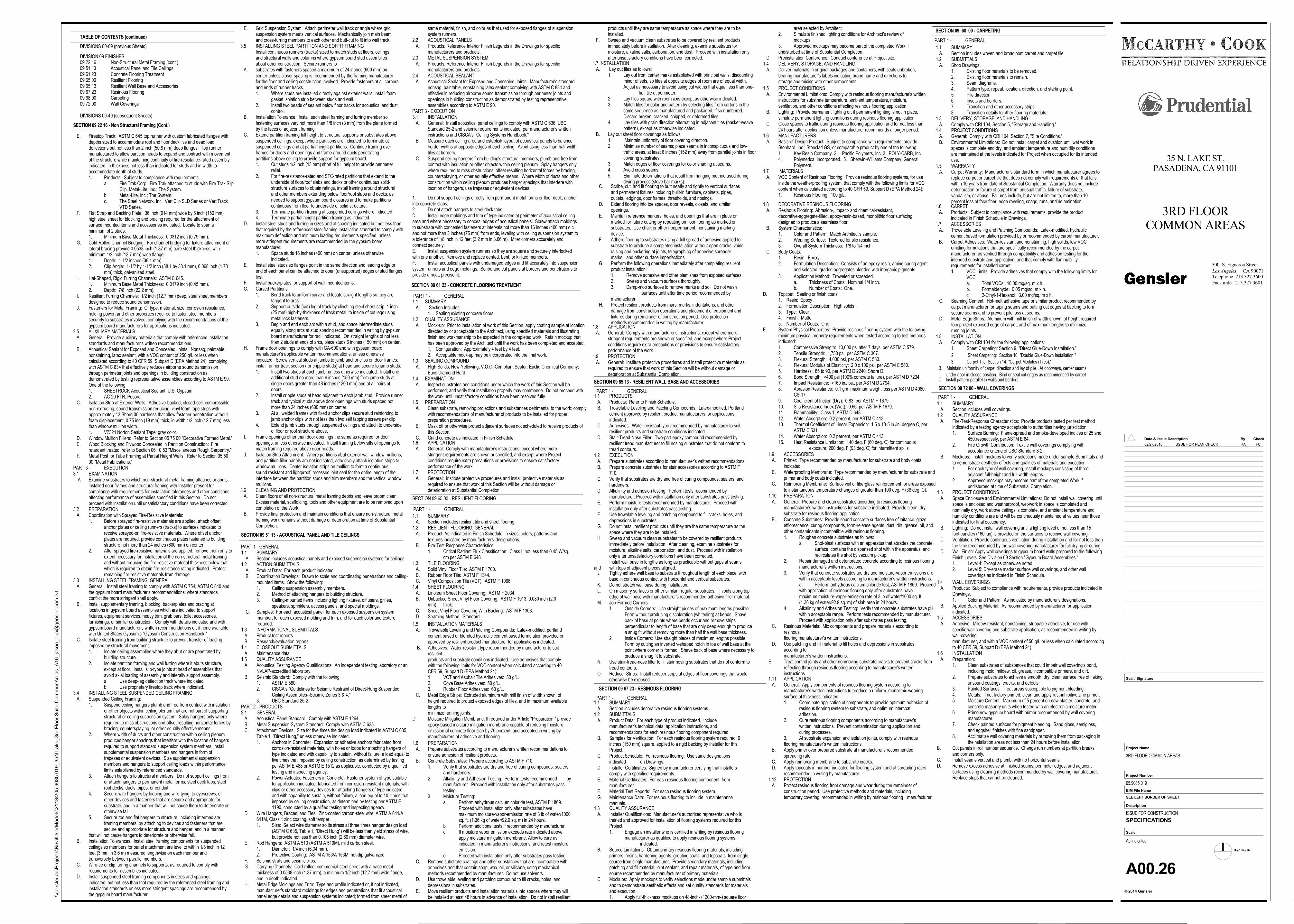
1. Cut studs 1/2 inch (13 mm) short of full height to provide perimeter relief.
2. For fire-resistance-rated and STC-rated partitions that extend to the underside of floor/roof slabs and decks or other continuous solid-structure surfaces to obtain ratings, install framing around structural and other members extending below floor/roof slabs and decks, as needed to support gypsum board closures and to make partitions continuous from floor to underside of solid structure.
3. Terminate partition framing at suspended ceilings where indicated.4. Terminate partial height partition framing as indicated.
D. Install steel studs and furring in sizes and at spacing indicated but not less thanthat required by the referenced steel framing installation standard to comply withmaximum deflection and minimum loading requirements specified, unlessmore stringent requirements are recommended by the gypsum boardmanufacturer:1. Space studs 16 inches (400 mm) on center, unless otherwise
indicated. E. Install steel studs so flanges point in the same direction and leading edge or
end of each panel can be attached to open (unsupported) edges of stud flangesfirst.
F. Install backerplates for support of wall mounted items. G. Curved Partitions:
1. Bend track to uniform curve and locate straight lengths so they are tangent to arcs.
2. Support outside (cut) leg of track by clinching steel sheet strip, 1 inch (25 mm) high-by-thickness of track metal, to inside of cut legs using metal lock fasteners.
3. Begin and end each arc with a stud, and space intermediate studs equally along arcs at stud spacing recommended in writing by gypsum board manufacturer for radii indicated. On straight lengths of not less than 2 studs at ends of arcs, place studs 6 inches (150 mm) on center.
H. Frame door openings to comply with GA-600 and with gypsum boardmanufacturer's applicable written recommendations, unless otherwiseindicated. Screw vertical studs at jambs to jamb anchor clips on door frames;install runner track section (for cripple studs) at head and secure to jamb studs.1. Install two studs at each jamb, unless otherwise indicated. Install one
additional stud no more than 6 inches (150 mm) from jamb studs at single doors greater than 48 inches (1200 mm) and at all pairs of doors.
2. Install cripple studs at head adjacent to each jamb stud. Provide runnertrack and typical studs above door openings with studs spaced not more than 24 inches (600 mm) on center.
3. At all welded frames with fixed anchor clips secure stud reinforcing to jamb anchor clips with not less than two self tapping screws per clip.
4. Extend jamb studs through suspended ceilings and attach to undersideof floor or roof structure above.
I. Frame openings other than door openings the same as required for dooropenings, unless otherwise indicated. Install framing below sills of openings tomatch framing required above door heads.
J. Isolation Strip Attachment: Where partitions abut exterior wall window mullions,and partition filler panels are not indicated, adhesively attach isolation strips towindow mullions. Center isolation strips on mullion to form a continuous,sound resistant and lightproof, recessed joint seal for the entire length of theinterface between the partition studs and trim members and the vertical windowmullions.
3.6 CLEANING AND PROTECTION A. Clean floors of all non-structural metal framing debris and leave broom clean.
Excess material, scaffolding, tools and other equipment are to be removed uponcompletion of the Work.
B. Provide final protection and maintain conditions that ensure non-structural metalframing work remains without damage or deterioration at time of SubstantialCompletion.
SECTION 09 51 13 - ACOUSTICAL PANEL AND TILE CEILINGS
PART 1 - GENERAL1.1 SUMMARY A. Section includes acoustical panels and exposed suspension systems for ceilings.1.2 ACTION SUBMITTALS A. Product Data: For each product indicated. B. Coordination Drawings: Drawn to scale and coordinating penetrations and ceiling-
mounted items. Show the following:1. Ceiling suspension assembly members.2. Method of attaching hangers to building structure.3. Ceiling-mounted items including lighting fixtures, diffusers, grilles,
speakers, sprinklers, access panels, and special moldings. C. Samples: For each acoustical panel, for each exposed suspension system
member, for each exposed molding and trim, and for each color and texturerequired.
1.3 INFORMATIONAL SUBMITTALS A. Product test reports. B. Research/evaluation reports.1.4 CLOSEOUT SUBMITTALS A. Maintenance data.1.5 QUALITY ASSURANCE A. Acoustical Testing Agency Qualifications: An independent testing laboratory or an
NVLAP-accredited laboratory. B. Seismic Standard: Comply with the following:
1. ASTM E 580.2. CISCA's "Guidelines for Seismic Restraint of Direct-Hung Suspended
Ceiling Assemblies--Seismic Zones 3 & 4."3. UBC Standard 25-2.
PART 2 - PRODUCTS2.1 GENERAL A. Acoustical Panel Standard: Comply with ASTM E 1264. B. Metal Suspension System Standard: Comply with ASTM C 635. C. Attachment Devices: Size for five times the design load indicated in ASTM C 635,
Table 1, "Direct Hung," unless otherwise indicated.1. Anchors in Concrete: Expansion or adhesive anchors fabricated from
corrosion-resistant materials, with holes or loops for attaching hangers of type indicated and with capability to sustain, without failure, a load equal tofive times that imposed by ceiling construction, as determined by testing per ASTM E 488 or ASTM E 1512 as applicable, conducted by a qualified testing and inspecting agency.
2. Power-Actuated Fasteners in Concrete: Fastener system of type suitable for application indicated, fabricated from corrosion-resistant materials, withclips or other accessory devices for attaching hangers of type indicated, and with capability to sustain, without failure, a load equal to 10 times thatimposed by ceiling construction, as determined by testing per ASTM E 1190, conducted by a qualified testing and inspecting agency.
D. Wire Hangers, Braces, and Ties: Zinc-coated carbon-steel wire; ASTM A 641/A641M, Class 1 zinc coating, soft temper.1. Size: Select wire diameter so its stress at three times hanger design load
(ASTM C 635, Table 1, "Direct Hung") will be less than yield stress of wire, but provide not less than 0.106 inch (2.69 mm) diameter wire.
E. Rod Hangers: ASTM A 510 (ASTM A 510M), mild carbon steel.1. Diameter: 1/4 inch (6.34 mm).2. Protective Coating: ASTM A 153/A 153M, hot-dip galvanized.
F. Seismic struts and seismic clips. G. Carrying Channels: Cold-rolled, commercial-steel sheet with a base metal
thickness of 0.0538 inch (1.37 mm), a minimum 1/2 inch (12.7 mm) wide flange,and in depth indicated.
H. Metal Edge Moldings and Trim: Type and profile indicated or, if not indicated, manufacturer's standard moldings for edges and penetrations that fit acousticalpanel edge details and suspension systems indicated; formed from sheet metal of
1. Do not support ceilings directly from permanent metal forms or floor deck; anchorinto concrete slabs.2. Do not attach hangers to steel deck tabs.D. Install edge moldings and trim of type indicated at perimeter of acoustical ceilingarea and where necessary to conceal edges of acoustical panels. Screw attach moldingsto substrate with concealed fasteners at intervals not more than 16 inches (400 mm) o.c.and not more than 3 inches (75 mm) from ends, leveling with ceiling suspension system toa tolerance of 1/8 inch in 12 feet (3.2 mm in 3.66 m). Miter corners accurately andconnect securely.E. Install suspension system runners so they are square and securely interlockedwith one another. Remove and replace dented, bent, or kinked members.F. Install acoustical panels with undamaged edges and fit accurately into suspensionsystem runners and edge moldings. Scribe and cut panels at borders and penetrations toprovide a neat, precise fit.
SECTION 09 61 23 - CONCRETE FLOORING TREATMENT
1.1 SUMMARY A. Section Includes:
1. Sealing existing concrete floors.1.2 QUALITY ASSURANCE A. Mock-up: Prior to installation of work of this Section, apply coating sample at location
directed by or acceptable to the Architect, using specified materials and illustratingfinish and workmanship to be expected in the completed work. Retain mockup thathas been approved by the Architect until the work has been completed and accepted.1. Configuration: Approximately 4 feet by 4 feet.2. Acceptable mock-up may be incorporated into the final work.
1.3 SEALING COMPOUND A. High Solids, Now-Yellowing, V.O.C.-Compliant Sealer: Euclid Chemical Company;
Euco Diamond Hard.1.4 EXAMINATION A. Inspect substrates and conditions under which the work of this Section will be
performed, and verify that installation properly may commence. Do not proceed withthe work until unsatisfactory conditions have been resolved fully.
1.5 PREPARATION A. Clean substrate, removing projections and substances detrimental to the work; comply
with recommendations of manufacturer of products to be installed for properpreparation procedures.
B. Mask off or otherwise protect adjacent surfaces not scheduled to receive products ofthis Section.
C. Grind concrete as indicated in Finish Schedule.
1.7 INSTALLATION A. Lay out tiles as follows:
1. Lay out from center marks established with principal walls, discountingminor offsets, so tiles at opposite edges of room are of equal width. Adjust as necessary to avoid using cut widths that equal less than one-
half tile at perimeter.2. Lay tiles square with room axis except as otherwise indicated.3. Match tiles for color and pattern by selecting tiles from cartons in the
same sequence as manufactured and packaged, if so numbered. Discard broken, cracked, chipped, or deformed tiles.
4. Lay tiles with grain direction alternating in adjacent tiles (basket-weavepattern), except as otherwise indicated.
B. Lay out sheet floor coverings as follows:1. Maintain uniformity of floor covering direction.2. Minimize number of seams; place seams in inconspicuous and low-
traffic areas, at least 6 inches (152 mm) away from parallel joints in floorcovering substrates.
3. Match edges of floor coverings for color shading at seams.4. Avoid cross seams.5. Eliminate deformations that result from hanging method used during
drying process (stove bar marks). C. Scribe, cut, and fit flooring to butt neatly and tightly to vertical surfaces
and permanent fixtures including built-in furniture, cabinets, pipes,outlets, edgings, door frames, thresholds, and nosings.
D. Extend flooring into toe spaces, door reveals, closets, and similaropenings.
E. Maintain reference markers, holes, and openings that are in place ormarked for future cutting by repeating on floor flooring as marked onsubstrates. Use chalk or other nonpermanent, nonstaining markingdevice.
F. Adhere flooring to substrates using a full spread of adhesive applied tosubstrate to produce a completed installation without open cracks, voids,raising and puckering at joints, telegraphing of adhesive spreadermarks, and other surface imperfections.
G. Perform the following operations immediately after completing resilientproduct installation:1. Remove adhesive and other blemishes from exposed surfaces.2. Sweep and vacuum surfaces thoroughly.3. Damp-mop surfaces to remove marks and soil. Do not wash
surfaces until after time period recommended bymanufacturer.
H. Protect resilient products from mars, marks, indentations, and otherdamage from construction operations and placement of equipment andfixtures during remainder of construction period. Use protectionmethods recommended in writing by manufacturer.
1.6 PREPARATION A. Prepare substrates according to manufacturer's written recommendations to
ensure adhesion of resilient products. B. Concrete Substrates: Prepare according to ASTM F 710.
1. Verify that substrates are dry and free of curing compounds, sealers,and hardeners.
2. Alkalinity and Adhesion Testing: Perform tests recommended bymanufacturer. Proceed with installation only after substrates passtesting.
3. Moisture Testing:a. Perform anhydrous calcium chloride test, ASTM F 1869.
Proceed with installation only after substrates have maximum moisture-vapor-emission rate of 3 lb of water/1000sq. ft. (1.36 kg of water/92.9 sq. m) in 24 hours.
b. Perform additional tests if recommended by manufacturer.c. If moisture vapor emission exceeds rate indicated above,
apply moisture mitigation membrane. Allow to cure as indicated in manufacturer's instructions, and retest moistureemission.
d. Proceed with installation only after substrates pass testing. C. Remove substrate coatings and other substances that are incompatible with
adhesives and that contain soap, wax, oil, or silicone, using mechanicalmethods recommended by manufacturer. Do not use solvents.
D. Use trowelable leveling and patching compound to fill cracks, holes, anddepressions in substrates.
E. Move resilient products and installation materials into spaces where they willbe installed at least 48 hours in advance of installation. Do not install resilient
1.1 SUMMARY A. Section includes resilient tile and sheet flooring.1.2 RESILIENT FLOORING, GENERAL A. Product: As indicated in Finish Schedule, in sizes, colors, patterns and
textures indicated by manufacturers' designations. B. Fire-Test-Response Characteristics:
1. Critical Radiant Flux Classification: Class I, not less than 0.45 W/sq.cm per ASTM E 648.
1.3 TILE FLOORING A. Solid Vinyl Floor Tile: ASTM F 1700. B. Rubber Floor Tile: ASTM F 1344. C. Vinyl Composition Tile (VCT): ASTM F 1066.1.4 SHEET FLOORING A. Linoleum Sheet Floor Covering: ASTM F 2034. B. Unbacked Sheet Vinyl Floor Covering: ASTM F 1913, 0.080 inch (2.0
mm) thick. C. Sheet Vinyl Floor Covering With Backing: ASTM F 1303. D. Seaming Method: Standard.
1.5 INSTALLATION MATERIALS A. Trowelable Leveling and Patching Compounds: Latex-modified, portland
cement based or blended hydraulic cement based formulation provided orapproved by resilient product manufacturer for applications indicated.
B. Adhesives: Water-resistant type recommended by manufacturer to suitresilientproducts and substrate conditions indicated. Use adhesives that complywith the following limits for VOC content when calculated according to 40CFR 59, Subpart D (EPA Method 24):1. VCT and Asphalt Tile Adhesives: 50 g/L.2. Cove Base Adhesives: 50 g/L.3. Rubber Floor Adhesives: 60 g/L.
C. Metal Edge Strips: Extruded aluminum with mill finish of width shown, ofheight required to protect exposed edges of tiles, and in maximum availablelengths tominimize running joints.
D. Moisture Mitigation Membrane: If required under Article "Preparation," provideepoxy-based moisture mitigation membrane capable of reducing moistureemission of concrete floor slab by 75 percent, and accepted in writing bymanufacturers of adhesive and flooring.
SECTION 09 65 00 - RESILIENT FLOORING
1.8 APPLICATION A. General: Comply with manufacturer's instructions, except where more
stringent requirements are shown or specified, and except where Projectconditions require extra precautions or provisions to ensure satisfactoryperformance of the work.
1.9 PROTECTION A. General: Institute protective procedures and install protective materials as
required to ensure that work of this Section will be without damage ordeterioration at Substantial Completion.
1.6 APPLICATION A. General: Comply with manufacturer's instructions, except where more
stringent requirements are shown or specified, and except where Projectconditions require extra precautions or provisions to ensure satisfactoryperformance of the work.
1.7 PROTECTION A. General: Institute protective procedures and install protective materials as
required to ensure that work of this Section will be without damage ordeterioration at Substantial Completion.
DIVISION 09 FINISHES09 22 16 Non-Structural Metal Framing (cont.)09 51 13 Acoustical Panel and Tile Ceilings09 61 23 Concrete Flooring Treatment09 65 00 Resilient Flooring09 65 13 Resilient Wall Base and Accessories09 67 23 Resinous Flooring09 68 00 Carpeting09 72 00 Wall Coverings
DIVISIONS 09-49 (subsequent Sheets)
TABLE OF CONTENTS (continued)
DIVISIONS 00-09 (previous Sheets)
E. Firestop Track: ASTM C 645 top runner with custom fabricated flanges withdepths sized to accommodate roof and floor deck live and dead loaddeflections but not less than 2 inch (50.8 mm) deep flanges. Top runnermanufactured to allow partition heads to expand and contract with movementof the structure while maintaining continuity of fire-resistance-rated assemblyindicated; in thickness not less than indicated for studs and in width toaccommodate depth of studs.1. Products: Subject to compliance with requirements
a. Fire Trak Corp.; Fire Trak attached to studs with Fire Trak SlipClip. Metal-Lite, Inc.; The System.
b. Metal-Lite, Inc.; The System.c. The Steel Network, Inc: VertiClip SLD Series or VertiTrack
VTD Series. F. Flat Strap and Backing Plate: 36 inch (914 mm) wide by 6 inch (150 mm)
high steel sheet for blocking and bracing required for the attachment ofsurface mounted items and accessories indicated. Locate to span aminimum of 2 studs.1. Minimum Base Metal Thickness: 0.0312 inch (0.79 mm).
G. Cold-Rolled Channel Bridging: For channel bridging for fixture attachment orlateral bracing provide 0.0538 inch (1.37 mm) bare steel thickness, withminimum 1/2 inch (12.7 mm) wide flange:1. Depth: 1-1/2 inches (38.1 mm).2. Clip Angle: 1-1/2 by 1-1/2 inch (38.1 by 38.1 mm), 0.068 inch (1.73
mm) thick, galvanized steel. H. Hat-Shaped, Rigid Furring Channels: ASTM C 645.
1. Minimum Base Metal Thickness: 0.0179 inch (0.45 mm).2. Depth: 7/8 inch (22.2 mm).
I. Resilient Furring Channels: 1/2 inch (12.7 mm) deep, steel sheet membersdesigned to reduce sound transmission.
J. Fasteners for Metal Framing: Of type, material, size, corrosion resistance,holding power, and other properties required to fasten steel memberssecurely to substrates involved; complying with the recommendations of thegypsum board manufacturers for applications indicated.
2.5 AUXILIARY MATERIALS A. General: Provide auxiliary materials that comply with referenced installation
standards and manufacturer's written recommendations. B. Acoustical Sealant for Exposed and Concealed Joints: Nonsag, paintable,
nonstaining, latex sealant, with a VOC content of 250 g/L or less whencalculated according to 40 CFR 59, Subpart D (EPA Method 24), complyingwith ASTM C 834 that effectively reduces airborne sound transmissionthrough perimeter joints and openings in building construction asdemonstrated by testing representative assemblies according to ASTM E 90.One of the following:1. SHEETROCK Acoustical Sealant; U.S. Gypsum.2. AC-20 FTR; Pecora.
C. Isolation Strip at Exterior Walls: Adhesive-backed, closed-cell, compressible,non-extruding, sound transmission reducing, vinyl foam tape strips withapproximately 13 Shore 00 hardness that allow fastener penetration withoutfoam displacement, 0.75 inch (19 mm) thick, in width 1/2 inch (12.7 mm) lessthan window mullion width.1. V7324 Norton Sealant Tape; gray color.
D. Window Mullion Fillers: Refer to Section 05 75 00 "Decorative Formed Metal." E. Wood Blocking and Plywood Concealed in Partition Construction: Fire
retardant treated, refer to Section 06 10 53 "Miscellaneous Rough Carpentry." F. Metal Post for Tube Framing at Partial Height Walls: Refer to Section 05 50
00 "Metal Fabrications."PART 3 - EXECUTION3.1 EXAMINATION A. Examine substrates to which non-structural metal framing attaches or abuts,
installed door frames and structural framing with Installer present forcompliance with requirements for installation tolerances and other conditionsaffecting performance of assemblies specified in this Section. Do notproceed with installation until unsatisfactory conditions have been corrected.
3.2 PREPARATION A. Coordination with Sprayed Fire-Resistive Materials:
1. Before sprayed fire-resistive materials are applied, attach offset anchor plates or ceiling runners (tracks) to surfaces indicated to receive sprayed-on fire-resistive materials. Where offset anchor plates are required, provide continuous plates fastened to buildingstructure not more than 24 inches (600 mm) on center.
2. After sprayed fire-resistive materials are applied, remove them only toextent necessary for installation of the non-structural metal framingand without reducing the fire-resistive material thickness below thatwhich is required to obtain fire-resistance rating indicated. Protectremaining fire-resistive materials from damage.
3.3 INSTALLING STEEL FRAMING, GENERAL A. General: Install steel framing to comply with ASTM C 754, ASTM C 840 and
the gypsum board manufacturer's recommendations, where standardsconflict the more stringent shall apply.
B. Install supplementary framing, blocking, backerplates and bracing atlocations in gypsum board assemblies which are indicated to supportfixtures, equipment services, heavy trim, grab bars, toilet accessories,furnishings, or similar construction. Comply with details indicated and withgypsum board manufacturer's written recommendations or, if none available,with United States Gypsum's "Gypsum Construction Handbook."
C. Isolate steel framing from building structure to prevent transfer of loadingimposed by structural movement.1. Isolate ceiling assemblies where they abut or are penetrated by
building structure.2. Isolate partition framing and wall furring where it abuts structure,
except at floor. Install slip-type joints at head of assemblies that avoid axial loading of assembly and laterally support assembly.a. Use deep-leg deflection track where indicated.b. Use proprietary firestop track where indicated.
3.4 INSTALLING STEEL SUSPENDED CEILING FRAMING A. Suspended Ceiling Framing:
1. Suspend ceiling hangers plumb and free from contact with insulationor other objects within ceiling plenum that are not part of supportingstructural or ceiling suspension system. Splay hangers only whererequired to miss obstructions and offset resulting horizontal forces bybracing, countersplaying, or other equally effective means.
2. Where width of ducts and other construction within ceiling plenumproduces hanger spacings that interfere with the location of hangersrequired to support standard suspension system members, installsupplemental suspension members and hangers in form of trapezes or equivalent devices. Size supplemental suspension members and hangers to support ceiling loads within performancelimits established by referenced standards.
3. Attach hangers to structural members. Do not support ceilings fromor attach hangers to permanent metal forms, steel deck tabs, steelroof decks, ducts, pipes, or conduit.
4. Secure wire hangers by looping and wire-tying, to eyescrews, or other devices and fasteners that are secure and appropriate for substrate, and in a manner that will not cause them to deteriorate orotherwise fail.
5. Secure rod and flat hangers to structure, including intermediate framing members, by attaching to devices and fasteners that are secure and appropriate for structure and hanger, and in a manner
that will not cause hangers to deteriorate or otherwise fail. B. Installation Tolerances: Install steel framing components for suspended
ceilings so members for panel attachment are level to within 1/8 inch in 12feet (3 mm in 3.6 m) measured lengthwise on each member andtransversely between parallel members.
C. Wire-tie or clip furring channels to supports, as required to comply withrequirements for assemblies indicated.
D. Install suspended steel framing components in sizes and spacingsindicated, but not less than that required by the referenced steel framing andinstallation standards unless more stringent spacings are recommended bythe gypsum board manufacturer.
SECTION 09 22 16 - Non Structural Framing (Cont.)
E. Grid Suspension System: Attach perimeter wall track or angle where gridsuspension system meets vertical surfaces. Mechanically join main beamand cross-furring members to each other and butt-cut to fit into wall track.
3.5 INSTALLING STEEL PARTITION AND SOFFIT FRAMINGInstall continuous runners (tracks) sized to match studs at floors, ceilings,and structural walls and columns where gypsum board stud assembliesabout other construction. Secure runners to
A. substrates with fasteners spaced a maximum of 24 inches (600 mm) oncenter unless closer spacing is recommended by the framing manufacturerfor the floor and ceiling construction involved. Provide fasteners at all cornersand ends of runner tracks.1. Where studs are installed directly against exterior walls, install foam
gasket isolation strip between studs and wall.2. Install two beads of sealant below floor tracks for acoustical and dust
control. B. Installation Tolerance: Install each steel framing and furring member so
fastening surfaces vary not more than 1/8 inch (3 mm) from the plane formedby the faces of adjacent framing.
C. Extend partition framing full height to structural supports or substrates abovesuspended ceilings, except where partitions are indicated to terminate atsuspended ceilings and at partial height partitions. Continue framing overframes for doors and openings and frame around ducts penetratingpartitions above ceiling to provide support for gypsum board.
same material, finish, and color as that used for exposed flanges of suspensionsystem runners.
2.2 ACOUSTICAL PANELS A. Products: Reference Interior Finish Legends in the Drawings for specific
manufacturers and products.2.3 METAL SUSPENSION SYSTEM A. Products: Reference Interior Finish Legends in the Drawings for specific
manufacturers and products.2.4 ACOUSTICAL SEALANT A. Acoustical Sealant for Exposed and Concealed Joints: Manufacturer's standard
nonsag, paintable, nonstaining latex sealant complying with ASTM C 834 andeffective in reducing airborne sound transmission through perimeter joints andopenings in building construction as demonstrated by testing representativeassemblies according to ASTM E 90.
PART 3 - EXECUTION3.1 INSTALLATION A. General: Install acoustical panel ceilings to comply with ASTM C 636, UBC
Standard 25-2 and seismic requirements indicated, per manufacturer's writteninstructions and CISCA's "Ceiling Systems Handbook."
B. Measure each ceiling area and establish layout of acoustical panels to balanceborder widths at opposite edges of each ceiling. Avoid using less-than-half-widthtiles at borders.
C. Suspend ceiling hangers from building's structural members, plumb and free fromcontact with insulation or other objects within ceiling plenum. Splay hangers onlywhere required to miss obstructions; offset resulting horizontal forces by bracing,countersplaying, or other equally effective means. Where width of ducts and otherconstruction within ceiling plenum produces hanger spacings that interfere withlocation of hangers, use trapezes or equivalent devices.
PART 1 - GENERAL
products until they are same temperature as space where they are to beinstalled.
F. Sweep and vacuum clean substrates to be covered by resilient productsimmediately before installation. After cleaning, examine substrates formoisture, alkaline salts, carbonation, and dust. Proceed with installation onlyafter unsatisfactory conditions have been corrected.
SECTION 09 65 13 - RESILIENT WALL BASE AND ACCESSORIES
SECTION 09 67 23 - RESINOUS FLOORING
1.1 PRODUCTS A. Products: Refer to Finish Schedule. B. Trowelable Leveling and Patching Compounds: Latex-modified, Portland
cement approved by resilient product manufacturers for applicationsindicated.
C. Adhesives: Water-resistant type recommended by manufacturer to suitresilient products and substrate conditions indicated.
D. Stair-Tread-Nose Filler: Two-part epoxy compound recommended byresilient tread manufacturer to fill nosing substrates that do not conform totread contours.
1.2 EXECUTION A. Prepare substrates according to manufacturer's written recommendations. B. Prepare concrete substrates for stair accessories according to ASTM F
710. C. Verify that substrates are dry and free of curing compounds, sealers, and
hardeners. D. Alkalinity and adhesion testing: Perform tests recommended by
manufacturer. Proceed with installation only after substrates pass testing. E. Perform moisture tests recommended by manufacturer. Proceed with
installation only after substrates pass testing. F. Use trowelable leveling and patching compound to fill cracks, holes, and
depressions in substrates. G. Do not install resilient products until they are the same temperature as the
space where they are to be installed. H. Sweep and vacuum clean substrates to be covered by resilient products
immediately before installation. After cleaning, examine substrates formoisture, alkaline salts, carbonation, and dust. Proceed with installationonly after unsatisfactory conditions have been corrected.
I. Install wall base in lengths as long as practicable without gaps at seamsand with tops of adjacent pieces aligned. J. Tightly adhere wall base to substrate throughout length of each piece, with
base in continuous contact with horizontal and vertical substrates. K. Do not stretch wall base during installation. L. On masonry surfaces or other similar irregular substrates, fill voids along top
edge of wall base with manufacturer's recommended adhesive filler material. M. Job-Formed Corners:
1. Outside Corners: Use straight pieces of maximum lengths possible. Form without producing discoloration (whitening) at bends. Shave back of base at points where bends occur and remove strips perpendicular to length of base that are only deep enough to produce a snug fit without removing more than half the wall base thickness.
2. Inside Corners: Use straight pieces of maximum lengths possible. Form by cutting an inverted v-shaped notch in toe of wall base at the point where corner is formed. Shave back of base where necessary toproduce a snug fit to substrate.
N. Use stair-tread-nose filler to fill stair nosing substrates that do not conform totread contours.
O. Reducer Strips: Install reducer strips at edges of floor coverings that wouldotherwise be exposed.
1.1 SUMMARY A. Section includes decorative resinous flooring systems.1.2 SUBMITTALS A. Product Data: For each type of product indicated. Include
manufacturer's technical data, application instructions, andrecommendations for each resinous flooring component required.
B. Samples for Verification: For each resinous flooring system required, 6inches (150 mm) square, applied to a rigid backing by Installer for thisProject.
C. Product Schedule: For resinous flooring. Use same designationsindicated on Drawings.
D. Installer Certificates: Signed by manufacturer certifying that installerscomply with specified requirements.
E. Material Certificates: For each resinous flooring component, frommanufacturer.
F. Material Test Reports: For each resinous flooring system. G. Maintenance Data: For resinous flooring to include in maintenance
manuals.1.3 QUALITY ASSURANCE A. Installer Qualifications: Manufacturer's authorized representative who is
trained and approved for installation of flooring systems required for thisProject.1. Engage an installer who is certified in writing by resinous flooring
manufacturer as qualified to apply resinous flooring systems indicated.
B. Source Limitations: Obtain primary resinous flooring materials, includingprimers, resins, hardening agents, grouting coats, and topcoats, from singlesource from single manufacturer. Provide secondary materials, includingpatching and fill material, joint sealant, and repair materials, of type and fromsource recommended by manufacturer of primary materials.
C. Mockups: Apply mockups to verify selections made under sample submittalsand to demonstrate aesthetic effects and set quality standards for materialsand execution.1. Apply full-thickness mockups on 48-inch- (1200-mm-) square floor
area selected by Architect.2. Simulate finished lighting conditions for Architect's review of
mockups.3. Approved mockups may become part of the completed Work if undisturbed at time of Substantial Completion.
D. Preinstallation Conference: Conduct conference at Project site.1.4 DELIVERY, STORAGE, AND HANDLING A. Deliver materials in original packages and containers, with seals unbroken,
bearing manufacturer's labels indicating brand name and directions forstorage and mixing with other components.
1.5 PROJECT CONDITIONS A. Environmental Limitations: Comply with resinous flooring manufacturer's written
instructions for substrate temperature, ambient temperature, moisture,ventilation, and other conditions affecting resinous flooring application.
B. Lighting: Provide permanent lighting or, if permanent lighting is not in place,simulate permanent lighting conditions during resinous flooring application.
C. Close spaces to traffic during resinous flooring application and for not less than24 hours after application unless manufacturer recommends a longer period.
1.6 MANUFACTURERS A. Basis-of-Design Product: Subject to compliance with requirements, provide
Stonhard, Inc.; Stonclad GS, or comparable product by one of the following:1. Key Resin Company. 2. Pacific Polymers, Inc. 3. POLY-CARB, Inc.4. Polymerica, Incorporated. 5. Sherwin-Williams Company; General
Polymers.1.7 MATERIALS A. VOC Content of Resinous Flooring: Provide resinous flooring systems, for use
inside the weatherproofing system, that comply with the following limits for VOCcontent when calculated according to 40 CFR 59, Subpart D (EPA Method 24):1. Resinous Flooring: 100 g/L.
1.8 DECORATIVE RESINOUS FLOORING A. Resinous Flooring: Abrasion-, impact- and chemical-resistant,
decorative-aggregate-filled, epoxy-resin-based, monolithic floor surfacingdesigned to produce a seamless floor.
B. System Characteristics:1. Color and Pattern: Match Architect's sample.2. Wearing Surface: Textured for slip resistance.3. Overall System Thickness: 1/8 to 1/4 inch.
C. Body Coats:1. Resin: Epoxy.2. Formulation Description: Consists of an epoxy resin, amine curing agent
and selected, graded aggregates blended with inorganic pigments.
3. Application Method: Troweled or screeded.a. Thickness of Coats: Nominal 1/4 inch.b. Number of Coats: One.
D. Topcoat: Sealing or finish coats.1. Resin: Epoxy .2. Formulation Description: High solids .3. Type: Clear .4. Finish: Matte.5. Number of Coats: One .
E. System Physical Properties: Provide resinous flooring system with the followingminimum physical property requirements when tested according to test methodsindicated:1. Compressive Strength: 10,000 psi after 7 days, per ASTM C 579.2. Tensile Strength: 1,750 ps, per ASTM C 307.3. Flexural Strength: 4,000 psi, per ASTM C 580.4. Flexural Modulus of Elasticity: 2.0 x 10⁶ psi, per ASTM C 580.5. Hardness: 85 to 90, per ASTM D 2240, Shore D.6. Bond Strength: >400 psi (100% concrete failure), per ASTM D 7234.7. Impact Resistance: >160 in./lbs., per ASTM D 2794.8. Abrasion Resistance: 0.1 gm maximum weight loss per ASTM D 4060,
CS-17.9. Coefficient of friction (Dry): 0.83, per ASTM F 1679.10. Slip Resistance Index (Wet): 0.66, per ASTM F 1679.11. Flammability: Class 1, ASTM D 648.12. Water Absorption: 0.2 percent, per ASTM C 413.13. Thermal Coefficient of Linear Expansion: 1.5 x 10⁻⁵ in./in. degree C, per
ASTM C 531.14. Water Absorption: 0.2 percent, per ASTM C 413.15. Heat Resistance Limitation: 140 deg. F (60 deg. C) for continuous
exposure; 200 deg. F (93 deg. C) for intermittent spills.1.9 ACCESSORIES A. Primer: Type recommended by manufacturer for substrate and body coats
indicated. B. Waterproofing Membrane: Type recommended by manufacturer for substrate and
primer and body coats indicated. C. Reinforcing Membrane: Surface veil of fiberglass reinforcement for areas exposed
to instantaneous temperature changes of greater than 100 deg. F (38 deg. C).1.10 PREPARATION A. General: Prepare and clean substrates according to resinous flooring
manufacturer's written instructions for substrate indicated. Provide clean, drysubstrate for resinous flooring application.
B. Concrete Substrates: Provide sound concrete surfaces free of laitance, glaze,efflorescence, curing compounds, form-release agents, dust, dirt, grease, oil, andother contaminants incompatible with resinous flooring.1. Roughen concrete substrates as follows:
a. Shot-blast surfaces with an apparatus that abrades the concrete surface, contains the dispensed shot within the apparatus, and recirculates the shot by vacuum pickup.
2. Repair damaged and deteriorated concrete according to resinous flooringmanufacturer's written instructions.
3. Verify that concrete substrates are dry and moisture-vapor emissions are within acceptable levels according to manufacturer's written instructions.a. Perform anhydrous calcium chloride test, ASTM F 1869. Proceed with application of resinous flooring only after substrates have maximum moisture-vapor-emission rate of 3 lb of water/1000 sq. ft. (1.36 kg of water/92.9 sq. m) of slab area in 24 hours.
4. Alkalinity and Adhesion Testing: Verify that concrete substrates have pH within acceptable range. Perform tests recommended by manufacturer. Proceed with application only after substrates pass testing.
C. Resinous Materials: Mix components and prepare materials according toresinousflooring manufacturer's written instructions.
D. Use patching and fill material to fill holes and depressions in substratesaccording tomanufacturer's written instructions.
E. Treat control joints and other nonmoving substrate cracks to prevent cracks fromreflecting through resinous flooring according to manufacturer's writteninstructions.
1.11 APPLICATION A. General: Apply components of resinous flooring system according to
manufacturer's written instructions to produce a uniform, monolithic wearingsurface of thickness indicated.1. Coordinate application of components to provide optimum adhesion of
resinous flooring system to substrate, and optimum intercoat adhesion.
2. Cure resinous flooring components according to manufacturer's written instructions. Prevent contamination during application and curing processes.
3. At substrate expansion and isolation joints, comply with resinous flooring manufacturer's written instructions.
B. Apply primer over prepared substrate at manufacturer's recommendedspreading rate.
C. Apply reinforcing membrane to substrate cracks. D. Apply topcoats in number indicated for flooring system and at spreading rates
recommended in writing by manufacturer.1.12 PROTECTION A. Protect resinous flooring from damage and wear during the remainder of
construction period. Use protective methods and materials, includingtemporary covering, recommended in writing by resinous flooring manufacturer.
PART 1 - GENERAL
PART 1 - GENERAL
PART 1 - GENERAL
SECTION 09 68 00 - CARPETING
1.1 SUMMARY A. Section includes woven and broadloom carpet and carpet tile.1.2 SUBMITTALS A. Shop Drawings:
1. Existing floor materials to be removed.2. Existing floor materials to remain.3. Seam diagrams.4. Pattern type, repeat, location, direction, and starting point.5. Pile direction.6. Insets and borders.7. Transition and other accessory strips.8. Transition details to other flooring materials.
1.3 DELIVERY, STORAGE, AND HANDLING A. Comply with CRI 104, Section 5, "Storage and Handling."1.4 PROJECT CONDITIONS A. General: Comply with CRI 104, Section 7, "Site Conditions." B. Environmental Limitations: Do not install carpet and cushion until wet work in
spaces is complete and dry, and ambient temperature and humidity conditionsare maintained at the levels indicated for Project when occupied for its intendeduse.
1.5 WARRANTY A. Carpet Warranty: Manufacturer's standard form in which manufacturer agrees to
replace carpet or carpet tile that does not comply with requirements or that failswithin 10 years from date of Substantial Completion. Warranty does not includedeterioration or failure of carpet from unusual traffic, failure of substrate,vandalism, or abuse. Failures include, but are not limited to, more than 10percent loss of face fiber, edge raveling, snags, runs, and delamination.
1.6 CARPET A. Products: Subject to compliance with requirements, provide the product
indicated in Finish Schedule in Drawings.1.7 ACCESSORIES A. Trowelable Leveling and Patching Compounds: Latex-modified, hydraulic
cement based formulation provided by or recommended by carpet manufacturer. B. Carpet Adhesives: Water-resistant and nonstaining, high solids, low VOC
emitting formulations that are specifically recommended by the carpetmanufacturer, as verified through compatibility and adhesion testing for theintended substrate and application, and that comply with flammabilityrequirements for installed carpet:1. VOC Limits: Provide adhesives that comply with the following limits for
VOCa. Total VOCs: 10.00 mg/sq. m x h.b. Formaldehyde: 0.05 mg/sq. m x h.c. 2-Ethyl-1-Hexanol: 3.00 mg/sq. m x h.
2. Sheet Carpeting: Section 10, "Double Glue-Down Installation."3. Carpet Tile: Section 14, "Carpet Modules (Tiles)."
B. Maintain uniformity of carpet direction and lay of pile. At doorways, center seamsunder door in closed position. Bind or seal cut edges as recommended by carpet
C. Install pattern parallel to walls and borders.
C. Seaming Cement: Hot-melt adhesive tape or similar product recommended bycarpet manufacturer for taping seams and butting cut edges at backing to formsecure seams and to prevent pile loss at seams.
D. Metal Edge Strips: Aluminum with mill finish of width shown, of height requiredtom protect exposed edge of carpet, and of maximum lengths to minimizerunning joints.
1.8 INSTALLATION A. Comply with CRI 104 for the following applications:
1. Sheet Carpeting: Section 9, "Direct Glue-Down Installation."
SECTION 09 72 00 - WALL COVERINGS
1.1 SUMMARY A. Section includes wall coverings.1.2 QUALITY ASSURANCE A. Fire-Test-Response Characteristics: Provide products tested per test method
indicated by a testing agency acceptable to authorities having jurisdiction:1. Surface Burning: Flame-spread and smoke-developed indices of 25 and
450,respectively, per ASTM E 84.2. Fire Growth Contribution: Textile wall coverings complying with
acceptance criteria of UBC Standard 8-2. B. Mockups: Install mockups to verify selections made under sample Submittals and
to demonstrate aesthetic effects and qualities of materials and execution.1. For each type of wall covering, install mockups consisting of three
adjacent full-height and full-width lengths.2. Approved mockups may become part of the completed Work if
undisturbed at time of Substantial Completion.1.3 PROJECT CONDITIONS A. Space Enclosure and Environmental Limitations: Do not install wall covering until
space is enclosed and weatherproof, wet-work in space is completed andnominally dry, work above ceilings is complete, and ambient temperature andhumidity conditions are and will be continuously maintained at values near thoseindicated for final occupancy.
B. Lighting: Do not install wall covering until a lighting level of not less than 15foot-candles (160 lux) is provided on the surfaces to receive wall covering.
C. Ventilation: Provide continuous ventilation during installation and for not less thanthe time recommended by the wall covering manufacturer for full drying or curing.
D. Wall Finish: Apply wall coverings to gypsum board walls prepared to the followingFinish Levels. See Division 09 Section "Gypsum Board Assemblies."1. Level 4: Except as otherwise noted.2. Level 5: Dry-erase marker surface wall coverings, and other wall
coverings as indicated in Finish Schedule.
1.4 WALL COVERINGS A. Products: Subject to compliance with requirements, provide products indicated in
Drawings.1. Color and Pattern: As indicated by manufacturer's designations.
B. Applied Backing Material: As recommended by manufacturer for applicationindicated.
1.5 ACCESSORIES A. Adhesive: Mildew-resistant, nonstaining, strippable adhesive, for use with
specific wall covering and substrate application, as recommended in writing bywall-coveringmanufacturer, and with a VOC content of 50 g/L or less when calculated accordingto 40 CFR 59, Subpart D (EPA Method 24).
1.6 INSTALLATION A. Preparation:
1. Clean substrates of substances that could impair wall covering's bond,including mold, mildew, oil, grease, incompatible primers, and dirt.
2. Prepare substrates to achieve a smooth, dry, clean surface free of flaking,unsound coatings, cracks, and defects.
3. Painted Surfaces: Treat areas susceptible to pigment bleeding.4. Metals: If not factory primed, clean and apply rust-inhibitive zinc primer.5. Moisture Content: Maximum of 5 percent on new plaster, concrete, and
concrete masonry units when tested with an electronic moisture meter.6. Prime new gypsum board with primer recommended by wall covering
manufacturer.7. Check painted surfaces for pigment bleeding. Sand gloss, semigloss,
and eggshell finishes with fine sandpaper.8. Acclimatize wall covering materials by removing them from packaging in
theinstallation areas not less than 24 hours before installation.B. Cut panels in roll number sequence. Change run numbers at partition breaks
and corners only.C. Install seams vertical and plumb, with no horizontal seams.D. Remove excess adhesive at finished seams, perimeter edges, and adjacent
surfaces using cleaning methods recommended by wall covering manufacturer.Replace strips that cannot be cleaned.
PART 1 - GENERAL
PART 1 - GENERAL
Ref. North
CA 90071Los Angeles,
2014 Gensler
Project Number
BIM File Name
Scale
Description
c
Project Name
Seal / Signature
Check
Facsimile 213.327.3601
Telephone 213.327.3600
Date & By
500 S. Figueroa Street
Issue Description
SEE LEFT BORDER OF SHEET
\\ge
nsl
er.
ad\P
roje
cts
\RevitU
serM
od
els
\21
184
\05
.90
85.0
19
_35
N L
ake
_3rd
Flo
or
Su
ite C
om
mo
nA
reas_A
16_ja
son_o
pp@
gen
sle
r.com
.rvt
As indicated
35 N. LAKE ST.PASADENA, CA 91101
3RD FLOORCOMMON AREAS
3RD FLOOR COMMON AREAS
05.9085.019
ISSUE FOR CONSTRUCTION
A00.26
SPECIFICATIONS
02/27/2016 ISSUE FOR PLAN CHECK RA FC
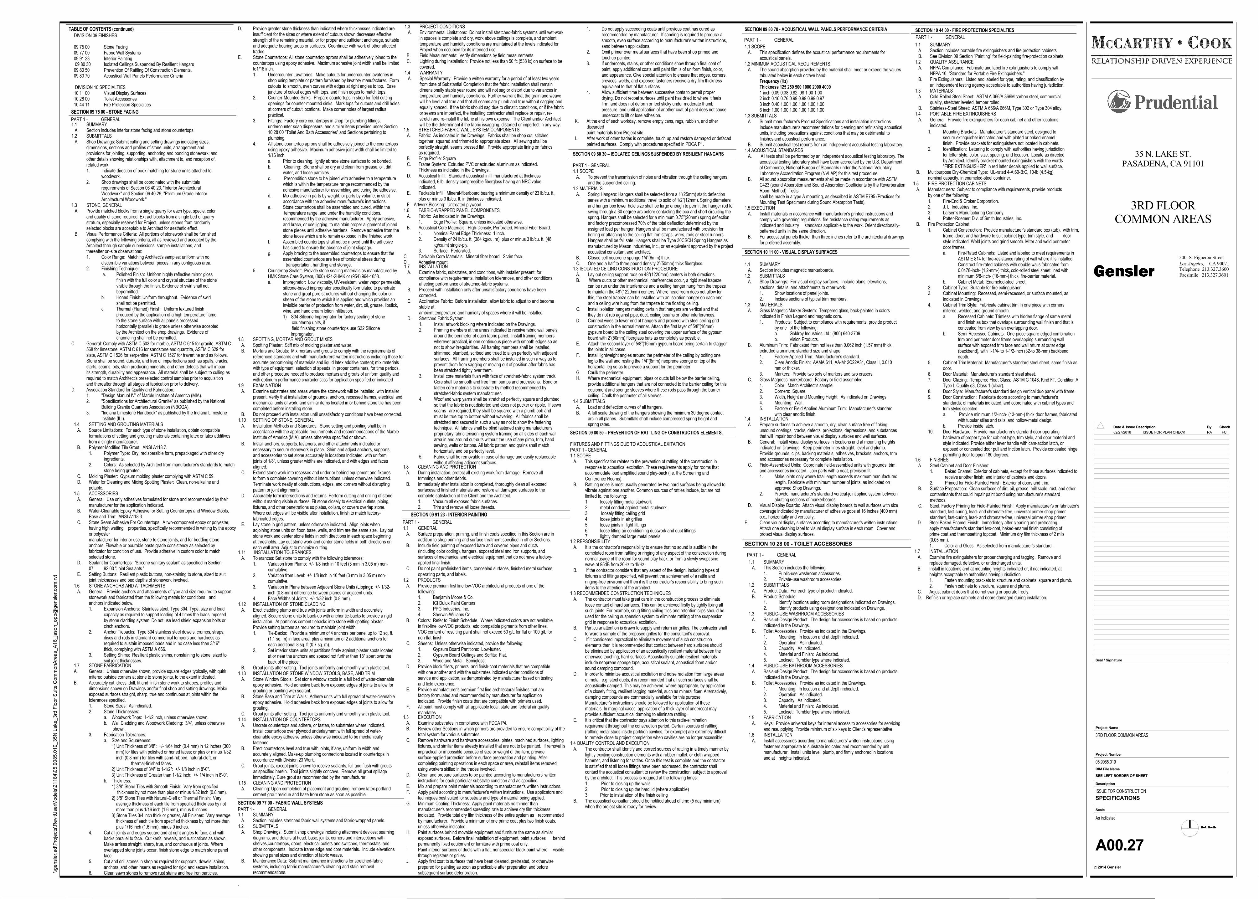
TABLE OF CONTENTS (continued)
SECTION 09 77 00 - FABRIC WALL SYSTEMS
SECTION 09 91 23 - INTERIOR PAINTING
DIVISION 09 FINISHES
09 75 00 Stone Facing09 77 00 Fabric Wall Systems09 91 23 Interior Painting 09 80 30 Isolated Ceilings Suspended By Resilient Hangars09 80 50 Prevention Of Rattling Of Construction Elements,09 80 70 Acoustical Wall Panels Performance Criteria
DIVISION 10 SPECIALTIES10 11 00 Visual Display Surfaces10 28 00 Toilet Accessories10 44 11 Fire Protection Specialties
1.4 SETTING AND GROUTING MATERIALS A. Source Limitations: For each type of stone installation, obtain compatible
formulations of setting and grouting materials containing latex or latex additivesfrom a single manufacturer.
B. Polymer-Modified Tile Grout: ANSI A118.7.1. Polymer Type: Dry, redispersible form, prepackaged with other dry
ingredients.2. Colors: As selected by Architect from manufacturer's standards to match
stone being grouted. C. Molding Plaster: Gypsum molding plaster complying with ASTM C 59. D. Water for Cleaning and Mixing Spotting Plaster: Clean, non-alkaline and
potable.1.5 ACCESSORIES A. General: Use only adhesives formulated for stone and recommended by their
manufacturer for the application indicated. B. Water-Cleanable Epoxy Adhesive for Setting Countertops and Window Stools,
Base and Trim: ANSI A118.3. C. Stone Seam Adhesive For Countertops: A two-component epoxy or polyester,
having high wetting properties, specifically recommended in writing by the epoxyor polyestermanufacturer for interior use, stone to stone joints, and for bedding stoneanchors. Flowable or pourable paste grade consistency as selected byfabricator for condition of use. Provide adhesive in custom color to matchselected stone.
D. Sealant for Countertops: 'Silicone sanitary sealant' as specified in Section07 92 00 "Joint Sealants."
E. Setting Buttons: Resilient plastic buttons, non-staining to stone, sized to suitjoint thicknesses and bed depths of stonework involved.
1.6 STONE ANCHORS AND ATTACHMENTS A. General: Provide anchors and attachments of type and size required to support
stonework and fabricated from the following metals for conditions andanchors indicated below.1. Expansion Anchors: Stainless steel, Type 304. Type, size and load
capacity as required to support loading of 4 times the loads imposed by stone cladding system. Do not use lead shield expansion bolts or cinch anchors.
2. Anchor Tiebacks: Type 304 stainless steel dowels, cramps, straps, discs and rods in standard commercial tempers and hardness as required to sustain imposed loads and in no case less than 3/16" thick, complying with ASTM A 666.
3. Setting Shims: Resilient plastic shims, nonstaining to stone, sized to suit joint thicknesses.
1.7 STONE FABRICATIONA. General: Unless otherwise shown, provide square edges typically, with quirk
mitered outside corners at stone to stone joints, to the extent indicated.B. Accurately cut, dress, drill, fit and finish stone work to shapes, profiles and
dimensions shown on Drawings and/or final shop and setting drawings. Makeexposed surfaces straight, sharp, true and continuous at joints within thetolerances specified.1. Stone Sizes: As indicated.2. Stone Thicknesses:
a. Woodwork Tops: 1-1/2 inch, unless otherwise shown.b. Wall Cladding and Woodwork Cladding: 3/4", unless otherwise shown.
3. Fabrication Tolerances:a. Size and Squareness: 1) Unit Thickness of 3/8": +/- 1/64 inch (0.4 mm) in 12 inches (300
mm) for tiles with polished or honed faces; or plus or minus 1/32 inch (0.8 mm) for tiles with sand-rubbed, natural-cleft, or
thermal-finished faces. 2) Unit Thickness of 3/4" to 1-1/2": +/- 1/8 inch in 8'-0". 3) Unit Thickness of Greater than 1-1/2 inch: +/- 1/4 inch in 8'-0".b. Thickness: 1) 3/8" Stone Tiles with Smooth Finish: Vary from specified thickness by not more than plus or minus 1/32 inch (0.8 mm). 2) 3/8" Stone Tiles with Natural-Cleft or Thermal Finish: Vary average thickness of each tile from specified thickness by not more than plus 1/16 inch (1.6 mm), minus 0 inches. 3) Stone Tiles 3/4 inch thick or greater, All Finishes: Vary average thickness of each tile from specified thickness by not more than plus 1/16 inch (1.6 mm), minus 0 inches.
4. Cut all joints and edges square and at right angles to face, and withbacks parallel to face. Cut kerfs, reveals, and rustications as shown.Make arrises straight, sharp, true, and continuous at joints. Whereoverlapped stone joints occur, finish stone edge to match stone panelface.
5. Cut and drill stones in shop as required for supports, dowels, shims,anchors, and other inserts as required for rigid and secure installation.
6. Clean sawn stones to remove rust stains and free iron particles.
D. Provide greater stone thickness than indicated where thicknesses indicated areinsufficient for the sizes or where extent of cutouts shown decreases effectivestrength of the remaining material, or for proper and sufficient anchorage, suitableand adequate bearing areas or surfaces. Coordinate with work of other affectedtrades.
E. Stone Countertops: All stone countertop aprons shall be adhesively joined to thecountertops using epoxy adhesive. Maximum adhesive joint width shall be limitedto1/16 inch.1. Undercounter Lavatories: Make cutouts for undercounter lavatories in
shop using template or pattern furnished by lavatory manufacturer. Formcutouts to smooth, even curves with edges at right angles to top. Ease juncture of cutout edges with tops, and finish edges to match tops.
2. Counter-Mounted Sinks: Prepare countertops in shop for field cutting openings for counter-mounted sinks. Mark tops for cutouts and drill holesat corners of cutout locations. Make corner holes of largest radius practical.
3. Fittings: Factory core countertops in shop for plumbing fittings, undercounter soap dispensers, and similar items provided under Section10 28 00 "Toilet And Bath Accessories" and Sections pertaining to plumbing.
4. All stone countertop aprons shall be adhesively joined to the countertopsusing epoxy adhesive. Maximum adhesive joint width shall be limited to1/16 inch.a. Prior to cleaning, lightly abrade stone surfaces to be bonded.b. Cleaning: Stone shall be dry and clean from grease, oil, dirt,
water, and loose particles.c. Precondition stone to be joined with adhesive to a temperature
which is within the temperature range recommended by the adhesive manufacturer for assembling and curing the adhesive.
d. Mix adhesive in parts by weight, or parts by volume, in strict accordance with the adhesive manufacturer's instructions.
e. Stone countertops shall be assembled and cured, within the temperature range, and under the humidity conditions, recommended by the adhesive manufacturer. Apply adhesive, and brace, or use jigging, to maintain proper alignment of joinedstone pieces until adhesive hardens. Remove adhesive from thestone faces which are to remain exposed in the finished work.
f. Assembled countertops shall not be moved until the adhesive has cured to ensure the absence of joint slippage.
g. Apply bracing to the assembled countertops to ensure that the assembled countertops are free of torsional stress during
transportation, handling and storage.5. Countertop Sealer: Provide stone sealing materials as manufactured by
HMK Stone Care System, (800) 424-2HMK or (954) 964-1658.a. Impregnator: Low viscosity, UV-resistant, water vapor permeable, silicone-based impregnator specifically formulated to penetrate
stone and grout pore structures without changing the color or sheen of the stone to which it is applied and which provides aninvisible barrier of protection from water, dirt, oil, grease, lipstick,wine, and hand cream lotion infiltration.1) S34 Silicone Impregnator for factory sealing of stone countertop units, if field finishing stone countertops use S32 Silicone Impregnator.
1.8 SPOTTING, MORTAR AND GROUT MIXES A. Spotting Plaster: Stiff mix of molding plaster and water. B. Mortars and Grouts: Mix mortars and grouts to comply with the requirements of
referenced standards and with manufacturers' written instructions including those foraccurate proportioning of materials and liquid latex additive content; mix materialswith type of equipment, selection of speeds, in proper containers, for time periods,and other procedure needed to produce mortars and grouts of uniform quality andwith optimum performance characteristics for application specified or indicated
1.9 EXAMINATION A. Examine substrates and areas where the stonework will be installed, with Installer
present. Verify that installation of grounds, anchors, recessed frames, electrical andmechanical units of work, and similar items located in or behind stone tile has beencompleted before installing stone.
B. Do not proceed with installation until unsatisfactory conditions have been corrected.1.10 SETTING OF STONE, GENERAL A. Installation Methods and Standards: Stone setting and pointing shall be in
accordance with the applicable requirements and recommendations of the MarbleInstitute of America (MIA), unless otherwise specified or shown.
1.11 INSTALLATION TOLERANCES A. Tolerances: Set stone to comply with the following tolerances:
1. Variation from Plumb: +/- 1/8 inch in 10 feet (3 mm in 3.05 m) non-cumulative.
2. Variation from Level: +/- 1/8 inch in 10 feet (3 mm in 3.05 m) non-cumulative.
3. Variation in Plane between Adjacent Stone Units (Lipping): +/- 1/32-inch (0.8-mm) difference between planes of adjacent units.
4. Face Widths of Joints: +/- 1/32 inch (0.8 mm).1.12 INSTALLATION OF STONE CLADDING A. Erect cladding plumb and true with joints uniform in width and accurately
aligned. Secure stone units to back-up with anchor tie-backs to provide a rigidinstallation. At partitions cement tiebacks into stone with spotting plaster.Provide setting buttons as required to maintain joint width.1. Tie-Backs: Provide a minimum of 4 anchors per panel up to 12 sq. ft.
(1.1 sq. m) in face area, plus a minimum of 2 additional anchors foreach additional 8 sq. ft.(0.7 sq. m).
2. Set interior stone units at partitions firmly against plaster spots locatedat or near the anchors and spaced not further than 18" apart over theback of the piece.
B. Grout joints after setting. Tool joints uniformly and smoothly with plastic tool.1.13 INSTALLATION OF STONE WINDOW STOOLS, BASE, AND TRIM A. Stone Window Stools: Set stone window stools in a full bed of water-cleanable
epoxy adhesive. Hold adhesive back from exposed edges of joints to allow forgrouting or pointing with sealant.
B. Stone Base and Trim at Walls: Adhere units with full spread of water-cleanableepoxy adhesive. Hold adhesive back from exposed edges of joints to allow forgrouting.
C. Grout joints after setting. Tool joints uniformly and smoothly with plastic tool.1.14 INSTALLATION OF COUNTERTOPS A. Uncrate countertops and adhere, or fasten, to substrates where indicated.
Install countertops over plywood underlayment with full spread of water-cleanable epoxy adhesive unless otherwise indicated to be mechanicallyfastened.
B. Erect countertops level and true with joints, if any, uniform in width andaccurately aligned. Make-up plumbing connections located in countertops inaccordance with Division 23 Work.
C. Grout joints, except joints shown to receive sealants, full and flush with groutsas specified herein. Tool joints slightly concave. Remove all grout spillageimmediately. Cure grout as recommended by the manufacturer.
1.15 CLEANING AND PROTECTION A. Cleaning: Upon completion of placement and grouting, remove latex-portland
cement grout residue and haze from stone as soon as possible.
1.1 SUMMARY A. Section includes stretched fabric wall systems and fabric-wrapped panels.1.2 SUBMITTALS A. Shop Drawings: Submit shop drawings including attachment devices; seaming
diagrams; and details at head, base, joints, corners and intersections withshelves,countertops, doors, electrical outlets and switches, thermostats, andother components. Indicate frame edge and core materials. Include elevationsshowing panel sizes and direction of fabric weave.
B. Maintenance Data: Submit maintenance instructions for stretched-fabricsystems, including fabric manufacturer's cleaning and stain removalrecommendations.
.
1.5 STRETCHED-FABRIC WALL SYSTEM COMPONENTS A. Fabric: As indicated in the Drawings. Fabrics shall be shop cut, stitched
together, squared and trimmed to appropriate sizes. All sewing shall beperfectly straight, seams pressed flat. Provide appropriate lining on fabricsas required.
B. Edge Profile: Square. C. Frame System: Extruded PVC or extruded aluminum as indicated.
Thickness as indicated in the Drawings. D. Acoustical Infill: Standard acoustical infill manufactured at thickness
indicated, 6 lb. density compressible fiberglass having an NRC valueindicated.
E. Tackable Infill: Mineral-fiberboard bearing a minimum density of 23 lb/cu. ft.,plus or minus 3 lb/cu. ft, in thickness indicated.
F. Artwork Blocking: Untreated plywood.1.6 FABRIC-WRAPPED PANEL COMPONENTS A. Fabric: As indicated in the Drawings.
1. Edge Profile: Square, unless indicated otherwise. B. Acoustical Core Materials: High-Density, Perforated, Mineral Fiber Board.
1. Nominal Panel Edge Thickness: 1 inch.2. Density of 24 lb/cu. ft. (384 kg/cu. m), plus or minus 3 lb/cu. ft. (48
kg/cu.m) single-ply.3. Surface: Perforated.
C. Tackable Core Materials: Mineral fiber board. Scrim face.D. Adhesive mount.1.7 INSTALLATION A. Examine fabric, substrates, and conditions, with Installer present, for
compliance with requirements, installation tolerances, and other conditionsaffecting performance of stretched-fabric systems.
B. Proceed with installation only after unsatisfactory conditions have beencorrected.
C. Acclimatize Fabric: Before installation, allow fabric to adjust to and becomestable atambient temperature and humidity of spaces where it will be installed.
D. Stretched Fabric System:1. Install artwork blocking where indicated on the Drawings.2. Framing members at the areas indicated to receive fabric wall panels
around the perimeter of each fabric panel. Install framing memberswherever practical, in one continuous piece with smooth edges so asnot to show irregularities. All framing members shall be installed,shimmed, plumbed, scribed and trued to align perfectly with adjacentsurfaces. All framing members shall be installed in such a way as toprevent them from sagging or moving out of position after fabric hasbeen stretched tightly over them.
3. Install core materials flush with face of stretched-fabric system track.Core shall be smooth and free from bumps and protrusions. Bond orfasten core materials to substrate by method recommended by stretched-fabric system manufacturer.
4. Woof and warp yarns shall be stretched perfectly square and plumbedso that the fabric is not distorted and does not pucker or ripple. If sewnseams are required, they shall be squared with a plumb bob andmust be true top to bottom without wavering. All fabrics shall be stretched and secured in such a way as not to show the fasteningtechnique. All fabrics shall be blind fastened using manufacturer'sproprietary fabric tensioning system framing on all sides of each wallarea in and around cut-outs without the use of any gimp, trim, handsewing, welts or batons. All fabric pattern and grains shall match horizontally and be perfectly level.
5. Fabric shall be removable in case of damage and easily replaceablewithout affecting adjacent surfaces.
1.1 GENERAL A. Surface preparation, priming, and finish coats specified in this Section are in
addition to shop priming and surface treatment specified in other Sections. B. Include field painting of exposed bare and covered pipes and ducts
(including color coding), hangers, exposed steel and iron supports, andsurfaces of mechanical and electrical equipment that do not have a factory-applied final finish.
C. Do not paint prefinished items, concealed surfaces, finished metal surfaces,operating parts, and labels.
1.2 PRODUCTS A. Provide premium first line low-VOC architectural products of one of the
following:1. Benjamin Moore & Co.2. ICI Dulux Paint Centers3. PPG Industries, Inc.4. Sherwin-Williams Co.
B. Colors: Refer to Finish Schedule. Where indicated colors are not availablein first-line low-VOC products, add compatible pigments from other lines.VOC content of resulting paint shall not exceed 50 g/L for flat or 100 g/L fornon-flat finish.
C. Sheens: Unless otherwise indicated, provide the following:1. Gypsum Board Partitions: Low-luster.2. Gypsum Board Ceilings and Soffits: Flat.3. Wood and Metal: Semigloss.
D. Provide block fillers, primers, and finish-coat materials that are compatiblewith one another and with the substrates indicated under conditions ofservice and application, as demonstrated by manufacturer based on testingand field experience.
E. Provide manufacturer's premium first line architectural finishes that arefactory formulated and recommended by manufacturer for applicationindicated. Provide finish coats that are compatible with primers used.
F. All paint must comply with all applicable local, state and federal air qualitymandates.
G. Minimum Coating Thickness: Apply paint materials no thinner thanmanufacturer's recommended spreading rate to achieve dry film thicknessindicated. Provide total dry film thickness of the entire system as recommendedby manufacturer. Provide a minimum of one prime coat plus two finish coats,unless otherwise indicated.
H. Paint surfaces behind movable equipment and furniture the same as similarexposed surfaces. Before final installation of equipment, paint surfaces behindpermanently fixed equipment or furniture with prime coat only.
I. Paint interior surfaces of ducts with a flat, nonspecular black paint where visiblethrough registers or grilles.
J. Apply first coat to surfaces that have been cleaned, pretreated, or otherwiseprepared for painting as soon as practicable after preparation and beforesubsequent surface deterioration.
B. Install anchors, supports, fasteners, and other attachments indicated ornecessary to secure stonework in place. Shim and adjust anchors, supports,and accessories to set stone accurately in locations indicated, with uniformjoints of 1/8", unless greater widths are indicated, and with edges and facesaligned.
C. Extend stone work into recesses and under or behind equipment and fixturesto form a complete covering without interruptions, unless otherwise indicated.Terminate work neatly at obstructions, edges, and corners without disruptingpattern or joint alignments.
D. Accurately form intersections and returns. Perform cutting and drilling of stonewithout marring visible surfaces. Fit stone closely to electrical outlets, piping,fixtures, and other penetrations so plates, collars, or covers overlap stone.Where cut edges will be visible after installation, finish to match factory-fabricated edges.
E. Lay stone in grid pattern, unless otherwise indicated. Align joints when adjoining stone units on floor, base, walls, and trim are the same size. Lay outstone work and center stone fields in both directions in each space beginningat thresholds. Lay out stone work and center stone fields in both directions oneach wall area. Adjust to minimize cutting.
1.8 CLEANING AND PROTECTION A. During installation, protect all existing work from damage. Remove all
trimmings and other debris. B. Immediately after installation is completed, thoroughly clean all exposed
surfacesand finished materials and restore all damaged surfaces to thecomplete satisfaction of the Client and the Architect.1. Vacuum all exposed fabric surfaces.2. Trim and remove all loose threads.
SECTION 10 28 00 - TOILET ACCESSORIES
1.1 SUMMARY A. This Section includes the following:
1. Public-use washroom accessories.2. Private-use washroom accessories.
1.2 SUBMITTALS A. Product Data: For each type of product indicated. B. Product Schedule:
1. Identify locations using room designations indicated on Drawings.2. Identify products using designations indicated on Drawings.
1.3 PUBLIC-USE WASHROOM ACCESSORIES A. Basis-of-Design Product: The design for accessories is based on products
indicated in the Drawings. B. Toilet Accessories: Provide as indicated in the Drawings.
1. Mounting: In location and at depth indicated.2. Operation: As indicated.3. Capacity: As indicated.4. Material and Finish: As indicated.5. Lockset: Tumbler type where indicated.
1.4 PUBLIC-USE BATHROOM ACCESSORIES A. Basis-of-Design Product: The design for accessories is based on products
indicated in the Drawings. B. Toilet Accessories: Provide as indicated in the Drawings.
1. Mounting: In location and at depth indicated.2. Operation: As indicated.3. Capacity: As indicated.4. Material and Finish: As indicated.5. Lockset: Tumbler type where indicated.
1.5 FABRICATION A. Keys: Provide universal keys for internal access to accessories for servicing
and resu pplying. Provide minimum of six keys to Client's representative.1.6 INSTALLATION A. Install accessories according to manufacturers' written instructions, using
fasteners appropriate to substrate indicated and recommended by unitmanufacturer. Install units level, plumb, and firmly anchored in locationsand at heights indicated.
SECTION 09 75 00 - STONE FACING
1.1 SUMMARY A. Section includes interior stone facing and stone countertops.1.2 SUBMITTALS A. Shop Drawings: Submit cutting and setting drawings indicating sizes,
dimensions, sections and profiles of stone units, arrangement andprovisions for jointing, supporting, anchoring and bonding stonework; andother details showing relationships with, attachment to, and reception of,related work.1. Indicate direction of book matching for stone units attached to
woodwork.2. Shop drawings shall be coordinated with the submittals
requirements of Section 06 40 23, "Interior Architectural Woodwork" and Section 06 40 29, "Premium Grade Interior Architectural Woodwork."
1.3 STONE, GENERAL A. Provide matched blocks from a single quarry for each type, specie, color
and quality of stone required. Extract blocks from a single bed of quarrystratum, especially reserved for Project, unless stones from randomlyselected blocks are acceptable to Architect for aesthetic effect.
B. Visual Performance Criteria: All portions of stonework shall be furnishedcomplying with the following criteria, all as reviewed and accepted by theArchitect through sample submissions, sample installations, andthereafter on-site observations:1. Color Range: Matching Architect's samples; uniform with no
discernible variations between pieces in any contiguous area.2. Finishing Technique:
a. Polished Finish: Uniform highly reflective mirror glossfinish with the full color and crystal structure of the stonevisible through the finish. Evidence of swirl shall not bepermitted.
b. Honed Finish: Uniform throughout. Evidence of swirlshall not be permitted.
c. Thermal (Flamed) Finish: Uniform textured finish produced by the application of a high temperature flameto the stone surface with all panels processed horizontally (parallel) to grade unless otherwise acceptedby the Architect on the shop drawings. Evidence of channeling shall not be permitted.
C. General: Comply with ASTM C 503 for marble, ASTM C 615 for granite, ASTM C568 for limestone, ASTM C 616 for sandstone and quartzite, ASTM C 629 forslate, ASTM C 1526 for serpentine, ASTM C 1527 for travertine and as follows.Stone shall be sound, durable, and free of imperfections such as spalls, cracks,starts, seams, pits, stain producing minerals, and other defects that will impairits strength, durability and appearance. All material shall be subject to culling asrequired to match Architect's preselected control samples prior to acquisitionand thereafter through all stages of fabrication prior to delivery.
D. Association Standard for Quality and Fabrication:1. "Design Manual IV" of Marble Institute of America (MIA).2. "Specifications for Architectural Granite" as published by the National
Building Granite Quarriers Association (NBGQA).3. "Indiana Limestone Handbook" as published by the Indiana Limestone
Institute (ILI).
1.3 EXECUTION A. Examine substrates in compliance with PDCA P4. B. Review other Sections in which primers are provided to ensure compatibility of the
total system for various substrates. C. Remove hardware and hardware accessories, plates, machined surfaces, lighting
fixtures, and similar items already installed that are not to be painted. If removal isimpractical or impossible because of size or weight of the item, providesurface-applied protection before surface preparation and painting. Aftercompleting painting operations in each space or area, reinstall items removedusing workers skilled in the trades involved.
D. Clean and prepare surfaces to be painted according to manufacturers' writteninstructions for each particular substrate condition and as specified.
E. Mix and prepare paint materials according to manufacturer's written instructions. F. Apply paint according to manufacturer's written instructions. Use applicators and
techniques best suited for substrate and type of material being applied.
1.3 PROJECT CONDITIONS A. Environmental Limitations: Do not install stretched-fabric systems until wet-work
in spaces is complete and dry, work above ceilings is complete, and ambienttemperature and humidity conditions are maintained at the levels indicated forProject when occupied for its intended use.
B. Field Measurements: Verify dimensions by field measurements. C. Lighting during Installation: Provide not less than 50 fc (538 lx) on surface to be
covered.1.4 WARRANTY A. Special Warranty: Provide a written warranty for a period of at least two years
from date of Substantial Completion that the fabric installation shall remaindimensionally stable year round and will not sag or distort due to variances intemperature and humidity conditions. Further warrant that the grain and weavewill be level and true and that all seams are plumb and true without sagging andequally spaced. If the fabric should sag due to climatic conditions, or if the fabricor seams are imperfect, the installing contractor shall replace or repair, re-stretch and re-install the fabric at his own expense. The Client and/or Architectwill be the determinant if the fabric issagging, distorted or imperfect in any way.
1. Do not apply succeeding coats until previous coat has cured as recommended by manufacturer. If sanding is required to produce a smooth, even surface according to manufacturer's written instructions, sand between applications.
2. Omit primer over metal surfaces that have been shop primed and touchup painted.
3. If undercoats, stains, or other conditions show through final coat of paint, apply additional coats until paint film is of uniform finish, color, and appearance. Give special attention to ensure that edges, corners, crevices, welds, and exposed fasteners receive a dry film thickness equivalent to that of flat surfaces.
4. Allow sufficient time between successive coats to permit proper drying. Do not recoat surfaces until paint has dried to where it feels firm, and does not deform or feel sticky under moderate thumb pressure, and until application of another coat of paint does not cause undercoat to lift or lose adhesion.
K. At the end of each workday, remove empty cans, rags, rubbish, and otherdiscardedpaint materials from Project site.
L. After work of other trades is complete, touch up and restore damaged or defacedpainted surfaces. Comply with procedures specified in PDCA P1.
SECTION 10 44 00 - FIRE PROTECTION SPECIALTIES
1.1 SUMMARY A. Section includes portable fire extinguishers and fire protection cabinets. B. See Division 09 Section "Painting" for field-painting fire-protection cabinets.1.2 QUALITY ASSURANCE A. NFPA Compliance: Fabricate and label fire extinguishers to comply with
NFPA 10, "Standard for Portable Fire Extinguishers." B. Fire Extinguishers: Listed and labeled for type, rating, and classification by
an independent testing agency acceptable to authorities having jurisdiction.1.3 MATERIALS A. Cold-Rolled Steel Sheet: ASTM A 366/A 366M carbon steel, commercial
quality, stretcher leveled, temper rolled. B. Stainless-Steel Sheet: ASTM A 666/A 666M, Type 302 or Type 304 alloy.1.4 PORTABLE FIRE EXTINGUISHERS A. General: Provide fire extinguishers for each cabinet and other locations
indicated.
1. Fire-End & Croker Corporation.2. J. L. Industries, Inc.3. Larsen's Manufacturing Company.4. Potter-Roemer; Div. of Smith Industries, Inc.
B. Fire Protection Cabinet:1. Cabinet Construction: Provide manufacturer's standard box (tub), with trim,
frame, door, and hardware to suit cabinet type, trim style, and door style indicated. Weld joints and grind smooth. Miter and weld perimeter door frames.a. Fire-Rated Cabinets: Listed and labeled to meet requirements in
ASTM E 814 for fire-resistance rating of wall where it is installed. Construct fire-rated cabinets with double walls fabricated from 0.0478-inch- (1.2-mm-) thick, cold-rolled steel sheet lined with minimum 5/8-inch- (16-mm-) thick, fire-barrier material.
b. Cabinet Metal: Enameled-steel sheet.2. Cabinet Type: Suitable for fire extinguisher.3. Cabinet Mounting: Recessed, semi-recessed, or surface mounted, as
indicated in Drawings.4. Cabinet Trim Style: Fabricate cabinet trim in one piece with corners
mitered, welded, and ground smooth.a. Recessed Cabinets: Trimless with hidden flange of same metal
and finish as box that overlaps surrounding wall finish and that isconcealed from view by an overlapping door.
b. Semi-Recessed Cabinets: One-piece square-edged combinationtrim and perimeter door frame overlapping surrounding wall surface with exposed trim face and wall return at outer edge (backbend), with 1-1/4- to 1-1/2-inch (32-to 38-mm) backbend depth.
5. Cabinet Trim Material: Manufacturer's standard steel sheet, same finish asdoor.
6. Door Material: Manufacturer's standard steel sheet.7. Door Glazing: Tempered Float Glass: ASTM C 1048, Kind FT, Condition A,
Type I, Quality q3, Class 1 (clear).8. Door Style: Manufacturer's standard design vertical duo panel with frame.9. Door Construction: Fabricate doors according to manufacturer's
standards, of materials indicated, and coordinated with cabinet types and trim styles selected.a. Provide minimum 1/2-inch- (13-mm-) thick door frames, fabricated
with tubular stiles and rails, and hollow-metal design.b. Provide inside latch.
10. Door Hardware: Provide manufacturer's standard door-operating hardware of proper type for cabinet type, trim style, and door material and style indicated. Provide either lever handle with cam-action latch, or exposed or concealed door pull and friction latch. Provide concealed hingepermitting door to open 180 degrees.
1.6 FINISHES A. Steel Cabinet and Door Finishes:
1. Baked Enamel: Exterior of cabinets, except for those surfaces indicated to receive another finish; and interior of cabinets and doors.
2. Primed for Field-Painted Finish: Exterior of doors and trim. B. Surface Preparation: Clean surfaces of dirt, oil, grease, mill scale, rust, and other
contaminants that could impair paint bond using manufacturer's standardmethods.
C. Steel, Factory Priming for Field-Painted Finish: Apply manufacturer's or fabricator'sstandard, fast-curing, lead- and chromate-free, universal primer shop primerstandard, fast-curing, lead- and chromate-free, universal primer shop primer
D. Steel Baked-Enamel Finish: Immediately after cleaning and pretreating, apply manufacturer's standard two-coat, baked-enamel finish consisting ofprime coat and thermosetting topcoat. Minimum dry film thickness of 2 mils(0.05 mm).1. Color and Gloss: As selected from manufacturer's standard.
1.7 INSTALLATION A. Examine fire extinguishers for proper charging and tagging. Remove and
replace damaged, defective, or undercharged units. B. Install in locations and at mounting heights indicated or, if not indicated, at
heights acceptable to authorities having jurisdiction.1. Fasten mounting brackets to structure and cabinets, square and plumb.2. Fasten cabinets to structure, square and plumb.
C. Adjust cabinet doors that do not swing or operate freely. D. Refinish or replace cabinets and doors damaged during installation.
1. Mounting Brackets: Manufacturer's standard steel, designed to secure extinguisher indicated and with plated or baked-enamel finish. Provide brackets for extinguishers not located in cabinets.
2. Identification: Lettering to comply with authorities having jurisdictionfor letter style, color, size, spacing, and location. Locate as directedby Architect. Identify bracket-mounted extinguishers with the words"FIRE EXTINGUISHER" in red letter decals applied to wall surface.
B. Multipurpose Dry-Chemical Type: UL-rated 4-A:60-B:C, 10-lb (4.5-kg)nominal capacity, in enameled-steel container.
1.5 FIRE-PROTECTION CABINETS A. Manufacturers: Subject to compliance with requirements, provide products
by one of the following:
PART 1 - GENERAL
PART 1 - GENERAL
PART 1 - GENERAL
PART 1 - GENERAL
PART 1 - GENERAL
1.3 ISOLATED CEILING CONSTRUCTION PROCEDURE A. Lay out ceiling support rods on 48”(1220mm) centers in both directions. B. Where ducts or other mechanical interferences occur, a rigid steel trapeze
can be run under the interference and a ceiling hanger hung from the trapezeto maintain the 48”(1220mm) centers. Where head room does not allow forthis, the steel trapeze can be installed with an isolation hanger on each endand a ceiling wire hung from the trapeze to the floating ceiling.
C. Install isolation hangers making certain that hangers are vertical and thatthey do not rub against pipe, duct, ceiling beams or other interferences.
D. Connect wires to lower end of hangers and proceed with steel ceiling gridconstruction in the normal manner. Attach the first layer of 5/8”(16mm)gypsum board to the ceiling steel covering the upper surface of the gypsumboard with 2”(50mm) fiberglass bats as completely as possible.
E. Attach the second layer of 5/8”(16mm) gypsum board being certain to staggerthe joints in all cases.
F. Install lightweight angles around the perimeter of the ceiling by bolting oneleg to the wall and resting the 1/4”(6mm) neoprene sponge on top of thehorizontal leg so as to provide a support for the perimeter.
G. Caulk the perimeter. H. Where mechanical equipment, pipes or ducts fall below the barrier ceiling,
provide additional hangers that are not connected to the barrier ceiling for thisequipment and sponge sleeves where these rods pass through the barrierceiling. Caulk the perimeter of all sleeves.
1.4 SUBMITTALS A. Load and deflection curves of all hangers. B. A full scale drawing of the hangers showing the minimum 30 degree contact
arc in all planes. Submittals shall include compressed spring height andspring rates.
SECTION 09 80 50 – PREVENTION OF RATTLING OF CONSTRUCTION ELEMENTS,
FIXTURES AND FITTINGS DUE TO ACOUSTICAL EXITATIONPART 1 - GENERAL1.1 SCOPE A. This specification relates to the prevention of rattling of the construction in
response to acoustical excitation. These requirements apply for rooms thataccommodate loud amplified sound play-back (i.e. the Screening andConference Rooms).
B. Rattling noise is most usually generated by two hard surfaces being allowed tovibrate against one another. Common sources of rattles include, but are notlimited to, the following:1. loosely fitting metal studwork2. metal conduit against metal studwork3. loosely fitting ceiling grid4. loose joints in air grilles5. loose joints in light fittings6. loose fitting air conditioning ductwork and duct fittings7. lightly damped large metal panels
SECTION 09 80 70 - ACOUSTICAL WALL PANELS PERFORMANCE CRITERIA
1.1 SCOPE A. This specification defines the acoustical performance requirements for
acoustical panels.1.2 MINIMUM ACOUSTICAL REQUIREMENTS A. The sound absorption provided by the material shall meet or exceed the values
tabulated below in each octave band:Frequency (Hz)Thickness 125 250 500 1000 2000 40001 inch 0.09 0.38 0.82 .98 1.00 1.002 inch 0.16 0.76 0.99 0.99 0.99 0.973 inch 0.40 1.00 1.00 1.00 1.00 1.006 inch 1.00 1.00 1.00 1.00 1.00 1.00
1.3 SUBMITTALS A. Submit manufacturer's Product Specifications and installation instructions.
Include manufacturer's recommendations for cleaning and refinishing acousticalunits, including precautions against conditions that may be detrimental tofinishes and acoustical performance.
B. Submit acoustical test reports from an independent acoustical testing laboratory.1.4 ACOUSTICAL STANDARDS A. All tests shall be performed by an independent acoustical testing laboratory. The
acoustical testing laboratory shall have been accredited by the U.S. Departmentof Commerce, National Bureau of Standards under the National VoluntaryLaboratory Accreditation Program (NVLAP) for this test procedure.
B. All sound absorption measurements shall be made in accordance with ASTMC423 (sound Absorption and Sound Absorption Coefficients by the ReverberationRoom Method). Testsshall be made in a type A mounting, as described in ASTM E795 (Practices forMounting Test Specimens during Sound Absorption Tests).
1.5 EXECUTION A. Install materials in accordance with manufacturer's printed instructions and
comply with governing regulations, fire resistance rating requirements asindicated and industry standards applicable to the work. Orient directionally-patterned units in the same direction.
B. For acoustical panels thicker than three inches refer to the architectural drawingsfor preferred assembly.
SECTION 10 11 00 - VISUAL DISPLAY SURFACES
1.1 SUMMARY A. Section includes magnetic markerboards.1.2 SUBMITTALS A. Shop Drawings: For visual display surfaces. Include plans, elevations,
sections, details, and attachments to other work.1. Show locations of panel joints.2. Include sections of typical trim members.
1.3 MATERIALS A. Glass Magnetic Marker System: Tempered glass, back-painted in colors
indicated in Finish Legend and magnetic core.1. Products: Subject to compliance with requirements, provide product
by one of the following:a. Goldray Industries Ltd.; (800) 640-3709.b. Vision Products.
B. Aluminum Trim: Fabricated from not less than 0.062 inch (1.57 mm) thick,extruded aluminum; standard size and shape.1. Factory-Applied Trim: Manufacturer's standard.2. Clear Anodic Finish: AAMA 611, AA-M12C22A31, Class II, 0.010
mm or thicker.3. Markers: Provide two sets of markers and two erasers.
C. Glass Magnetic markerboard: Factory or field assembled.1. Color: Match Architect's sample.2. Corners: Square.3. Width, Height and Mounting Height: As indicated on Drawings.4. Mounting: Wall.5. Factory or Field Applied Aluminum Trim: Manufacturer's standard
with clear anodic finish.1.4 INSTALLATION A. Prepare surfaces to achieve a smooth, dry, clean surface free of flaking,
unsound coatings, cracks, defects, projections, depressions, and substancesthat will impair bond between visual display surfaces and wall surfaces.
B. General: Install visual display surfaces in locations and at mounting heightsindicated on Drawings. Keep perimeter lines straight, level and plumb.Provide grounds, clips, backing materials, adhesives, brackets, anchors, trimand accessories necessary for complete installation.
C. Field-Assembled Units: Coordinate field-assembled units with grounds, trimand accessories indicated. Join parts with a neat, precision fit.1. Make joints only where total length exceeds maximum manufactured
length. Fabricate with minimum number of joints, as indicated on approved Shop Drawings.
2. Provide manufacturer's standard vertical-joint spline system betweenabutting sections of markerboards.
D. Visual Display Boards: Attach visual display boards to wall surfaces with sizecoverage indicated by manufacturer of adhesive gobs at 16 inches (400 mm)o.c., horizontally and vertically.
E. Clean visual display surfaces according to manufacturer's written instructions.Attach one cleaning label to visual display surface in each room. Cover andprotect visual display surfaces.
SECTION 09 80 30 – ISOLATED CEILINGS SUSPENDED BY RESILIENT HANGARS
PART 1 - GENERAL1.1 SCOPE A. To prevent the transmission of noise and vibration through the ceiling hangers
and the suspended ceiling.1.2 MATERIALS A. Spring Hangers: Hangers shall be selected from a 1”(25mm) static deflection
series with a minimum additional travel to solid of 1/2”(12mm). Spring diametersand hanger box lower hole size shall be large enough to permit the hanger rod toswing through a 30 degree arc before contacting the box and short circuiting thespring. Hangers shall be selected for a minimum 0.75”(20mm) spring deflectionand factory precompressed 70% of the total deflection determined by theassigned load per hanger. Hangers shall be manufactured with provision forbolting or attaching to the ceiling flat iron straps, wires, rods or steel runners.Hangers shall be fail safe. Hangers shall be Type 30CSCH Spring Hangers asmanufactured by Mason Industries, Inc., or an equivalent approved by the projectacoustical consultant and architect.
B. Closed cell neoprene sponge 1/4”(6mm) thick. C. One and a half to three pound density 2”(50mm) thick fiberglass.
1.2 REPSONSIBILITY A. It is the contractor’s responsibility to ensure that no sound is audible in the
completed room from rattling or ringing of any aspect of the construction duringnormal usage of the room for sound play back, or from a slowly swept sinewave at 95dB from 20Hz to 1kHz.
B. If the contractor considers that any aspect of the design, including types offixtures and fittings specified, will prevent the achievement of a rattle andringing-free environment then it is the contractor’s responsibility to bring suchitems to the attention of the architect.
1.3 RECOMMENDED CONSTRUCTION TECHNIQUES A. The contractor must take great care in the construction process to eliminate
loose contact of hard surfaces. This can be achieved firstly by tightly fixing allsuch joints. For example, snug fitting ceiling tiles and retention clips should beused for the ceiling suspension system to eliminate rattling of the suspensiongrid in response to acoustical excitation.
B. Particular attention is drawn to supply and return air grilles. The contractor shallforward a sample of the proposed grilles for the consultant’s approval.
C. If it considered impractical to eliminate movement of such constructionelements then it is recommended that contact between hard surfaces shouldbe eliminated by application of an acoustically resilient material between theotherwise touching, hard surfaces. Acoustically suitable resilient materialsinclude neoprene sponge tape, acoustical sealant, acoustical foam and/orsound damping compound.
D. In order to minimize acoustical excitation and noise radiation from large areasof metal, e.g. steel ducts, it is recommended that all such surfaces shall beacoustically damped. This may be achieved, where appropriate, by applicationof a closely fitting, resilient lagging material, such as mineral fiber. Alternatively,damping compounds are commercially available for this purpose.Manufacturer’s instructions should be followed for application of thesematerials. In marginal cases, application of a thick layer of undercoat mayprovide sufficient acoustical damping to eliminate rattling.
E. It is critical that the contractor pays attention to this rattle-eliminationrequirement throughout the construction period. Certain sources of rattling(rattling metal studs inside partition cavities, for example) are extremely difficultto remedy close to project completion when cavities are no longer accessible.
1.4 QUALITY CONTROL AND EXECUTION A. The contractor shall identify and correct sources of rattling in a timely manner by
lightly exciting construction elements with a rubber mallet, or cloth wrappedhammer, and listening for rattles. Once this test is complete and the contractoris satisfied that all loose fittings have been addressed, the contractor shallcontact the acoustical consultant to review the construction, subject to approvalby the architect. This process is required at the following times:1. Prior to closing up the walls2. Prior to closing up the hard lid (where applicable)3. Prior to installation of the finish ceiling
B. The acoustical consultant should be notified ahead of time (5 day minimum)when the project site is ready for review.
PART 1 - GENERAL
Ref. North
CA 90071Los Angeles,
2014 Gensler
Project Number
BIM File Name
Scale
Description
c
Project Name
Seal / Signature
Check
Facsimile 213.327.3601
Telephone 213.327.3600
Date & By
500 S. Figueroa Street
Issue Description
SEE LEFT BORDER OF SHEET
\\ge
nsl
er.
ad\P
roje
cts
\RevitU
serM
od
els
\21
184
\05
.90
85.0
19
_35
N L
ake
_3rd
Flo
or
Su
ite C
om
mo
nA
reas_A
16_ja
son_o
pp@
gen
sle
r.com
.rvt
As indicated
35 N. LAKE ST.PASADENA, CA 91101
3RD FLOORCOMMON AREAS
3RD FLOOR COMMON AREAS
05.9085.019
ISSUE FOR CONSTRUCTION
A00.27
SPECIFICATIONS
02/27/2016 ISSUE FOR PLAN CHECK RA FC
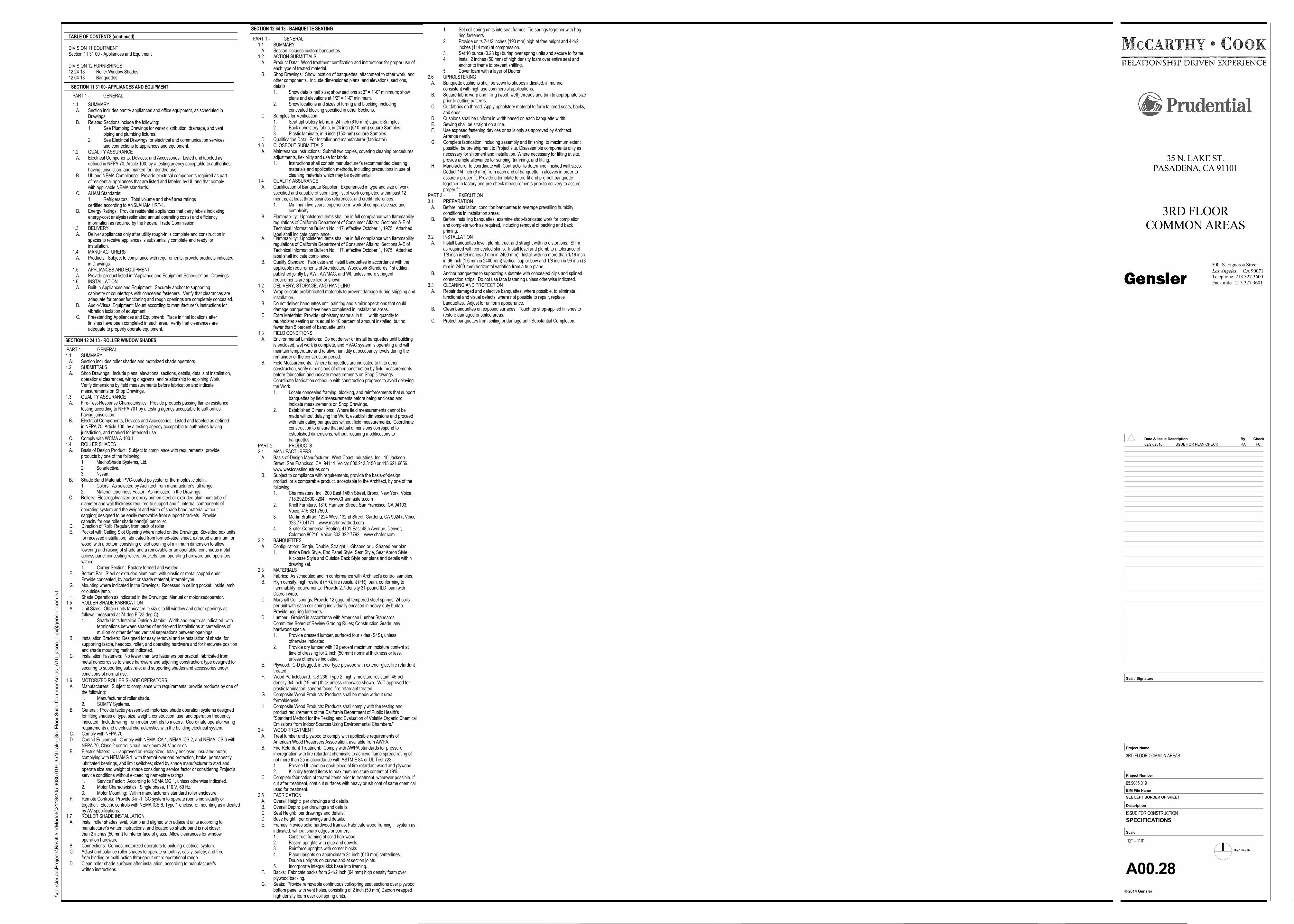
TABLE OF CONTENTS (continued)
SECTION 12 24 13 - ROLLER WINDOW SHADES
DIVISION 11 EQUITMENTSection 11 31 00 - Appliances and Equitment
DIVISION 12 FURNISHINGS12 24 13 Roller Window Shades12 64 13 Banquettes
1.1 SUMMARY A. Section includes roller shades and motorized shade operators.1.2 SUBMITTALS A. Shop Drawings: Include plans, elevations, sections, details, details of installation,
operational clearances, wiring diagrams, and relationship to adjoining Work.Verify dimensions by field measurements before fabrication and indicatemeasurements on Shop Drawings.
1.3 QUALITY ASSURANCE A. Fire-Test-Response Characteristics: Provide products passing flame-resistance
testing according to NFPA 701 by a testing agency acceptable to authoritieshaving jurisdiction.
B. Electrical Components, Devices and Accessories: Listed and labeled as definedin NFPA 70, Article 100, by a testing agency acceptable to authorities havingjurisdiction, and marked for intended use.
C. Comply with WCMA A 100.1.1.4 ROLLER SHADES A. Basis of Design Product: Subject to compliance with requirements, provide
products by one of the following:1. MechoShade Systems, Ltd.2. Solarfective.3. Nysan.
B. Shade Band Material: PVC-coated polyester or thermoplastic olefin.1. Colors: As selected by Architect from manufacturer's full range.2. Material Openness Factor: As indicated in the Drawings.
C. Rollers: Electrogalvanized or epoxy primed steel or extruded aluminum tube ofdiameter and wall thickness required to support and fit internal components ofoperating system and the weight and width of shade band material withoutsagging; designed to be easily removable from support brackets. Providecapacity for one roller shade band(s) per roller.
D. Direction of Roll: Regular, from back of roller. E. Pocket with Ceiling Slot Opening where noted on the Drawings: Six-sided box units
for recessed installation; fabricated from formed-steel sheet, extruded aluminum, orwood; with a bottom consisting of slot opening of minimum dimension to allowlowering and raising of shade and a removable or an openable, continuous metalaccess panel concealing rollers, brackets, and operating hardware and operatorswithin.1. Corner Section: Factory formed and welded.
F. Bottom Bar: Steel or extruded aluminum, with plastic or metal capped ends.Provide concealed, by pocket or shade material, internal-type.
G. Mounting where indicated in the Drawings: Recessed in ceiling pocket, inside jambor outside jamb.
H. Shade Operation as indicated in the Drawings: Manual or motorizedoperator.1.5 ROLLER SHADE FABRICATION A. Unit Sizes: Obtain units fabricated in sizes to fill window and other openings as
follows, measured at 74 deg F (23 deg C).1. Shade Units Installed Outside Jambs: Width and length as indicated, with
terminations between shades of end-to-end installations at centerlines of mullion or other defined vertical separations between openings.
B. Installation Brackets: Designed for easy removal and reinstallation of shade, forsupporting fascia, headbox, roller, and operating hardware and for hardware positionand shade mounting method indicated.
C. Installation Fasteners: No fewer than two fasteners per bracket, fabricated frommetal noncorrosive to shade hardware and adjoining construction; type designed forsecuring to supporting substrate; and supporting shades and accessories underconditions of normal use.
1.7 ROLLER SHADE INSTALLATION A. Install roller shades level, plumb and aligned with adjacent units according to
manufacturer's written instructions, and located so shade band is not closerthan 2 inches (50 mm) to interior face of glass. Allow clearances for windowoperation hardware.
B. Connections: Connect motorized operators to building electrical system. C. Adjust and balance roller shades to operate smoothly, easily, safety, and free
from binding or malfunction throughout entire operational range. D. Clean roller shade surfaces after installation, according to manufacturer's
written instructions.
1.6 MOTORIZED ROLLER SHADE OPERATORS A. Manufacturers: Subject to compliance with requirements, provide products by one of
the following:1. Manufacturer of roller shade.2. SOMFY Systems.
B. General: Provide factory-assembled motorized shade operation systems designedfor lifting shades of type, size, weight, construction, use, and operation frequencyindicated. Include wiring from motor controls to motors. Coordinate operator wiringrequirements and electrical characteristics with the building electrical system.
C. Comply with NFPA 70. D. Control Equipment: Comply with NEMA ICA 1, NEMA ICS 2, and NEMA ICS 6 with
NFPA 70, Class 2 control circuit, maximum 24-V ac or dc. E. Electric Motors: UL-approved or -recognized, totally enclosed, insulated motor,
complying with NEMAMG 1, with thermal-overload protection, brake, permanentlylubricated bearings, and limit switches; sized by shade manufacturer to start andoperate size and weight of shade considering service factor or considering Project'sservice conditions without exceeding nameplate ratings.1. Service Factor: According to NEMA MG 1, unless otherwise indicated.2. Motor Characteristics: Single phase, 110 V, 60 Hz.3. Motor Mounting: Within manufacturer's standard roller enclosure.
F. Remote Controls: Provide 3-in-1 IGC system to operate rooms individually ortogether. Electric controls with NEMA ICS 6, Type 1 enclosure, mounting as indicatedby AV specifications.
SECTION 12 64 13 - BANQUETTE SEATING
1.1 SUMMARY A. Section includes custom banquettes.1.2 ACTION SUBMITTALS A. Product Data: Wood treatment certification and instructions for proper use of
each type of treated material. B. Shop Drawings: Show location of banquettes, attachment to other work, and
other components. Include dimensioned plans, and elevations, sections,details.1. Show details half size; show sections at 3" = 1’-0" minimum; show
plans and elevations at 1/2" = 1'-0" minimum.2. Show locations and sizes of furring and blocking, including
concealed blocking specified in other Sections. C. Samples for Verification:
1. Seat upholstery fabric, in 24 inch (610-mm) square Samples.2. Back upholstery fabric, in 24 inch (610-mm) square Samples.3. Plastic laminate, in 6 inch (150-mm) square Samples.
D. Qualification Data: For Installer and manufacturer (fabricator).1.3 CLOSEOUT SUBMITTALS A. Maintenance Instructions: Submit two copies, covering cleaning procedures,
adjustments, flexibility and use for fabric.1. Instructions shall contain manufacturer's recommended cleaning
materials and application methods, including precautions in use ofcleaning materials which may be detrimental.
1.4 QUALITY ASSURANCE A. Qualification of Banquette Supplier: Experienced in type and size of work
specified and capable of submitting list of work completed within past 12months, at least three business references, and credit references.1. Minimum five years’ experience in work of comparable size and
complexity. B. Flammability: Upholstered items shall be in full compliance with flammability
regulations of California Department of Consumer Affairs: Sections A-E ofTechnical Information Bulletin No. 117, effective October 1, 1975. Attachedlabel shall indicate compliance.
A. Flammability: Upholstered items shall be in full compliance with flammabilityregulations of California Department of Consumer Affairs: Sections A-E ofTechnical Information Bulletin No. 117, effective October 1, 1975. Attachedlabel shall indicate compliance.
B. Quality Standard: Fabricate and install banquettes in accordance with theapplicable requirements of Architectural Woodwork Standards, 1st edition,published jointly by AWI, AWMAC, and WI, unless more stringentrequirements are specified or shown.
1.2 DELIVERY, STORAGE, AND HANDLING A. Wrap or crate prefabricated materials to prevent damage during shipping and
installation. B. Do not deliver banquettes until painting and similar operations that could
damage banquettes have been completed in installation areas. C. Extra Materials: Provide upholstery material in full‑width quantity to
reupholster seating units equal to 10 percent of amount installed, but nofewer than 5 percent of banquette units.
1.3 FIELD CONDITIONS A. Environmental Limitations: Do not deliver or install banquettes until building
is enclosed, wet work is complete, and HVAC system is operating and willmaintain temperature and relative humidity at occupancy levels during theremainder of the construction period.
B. Field Measurements: Where banquettes are indicated to fit to otherconstruction, verify dimensions of other construction by field measurementsbefore fabrication and indicate measurements on Shop Drawings.Coordinate fabrication schedule with construction progress to avoid delayingthe Work.1. Locate concealed framing, blocking, and reinforcements that support
banquettes by field measurements before being enclosed and indicate measurements on Shop Drawings.
2. Established Dimensions: Where field measurements cannot be made without delaying the Work, establish dimensions and proceedwith fabricating banquettes without field measurements. Coordinateconstruction to ensure that actual dimensions correspond to established dimensions, without requiring modifications to banquettes.
PART 2 - PRODUCTS2.1 MANUFACTURERS A. Basis-of-Design Manufacturer: West Coast Industries, Inc., 10 Jackson
Street, San Francisco, CA 94111, Voice: 800.243.3150 or 415.621.6656.www.westcoastindustries.com
B. Subject to compliance with requirements, provide the basis-of-designproduct, or a comparable product, acceptable to the Architect, by one of thefollowing:1. Chairmasters, Inc., 200 East 146th Street, Bronx, New York, Voice:
718.292.0600 x204. www.Chairmasters.com2. Knoll Furniture, 1810 Harrison Street, San Francisco, CA 94103,
Voice: 415.621.7500.3. Martin Brattrud, 1224 West 132nd Street, Gardena, CA 90247, Voice:
323.770.4171. www.martinbrattrud.com4. Shafer Commercial Seating, 4101 East 48th Avenue, Denver,
Colorado 80216, Voice: 303-322-7792. www.shafer.com2.2 BANQUETTES A. Configuration: Single, Double, Straight, L-Shaped or U-Shaped per plan.
1. Inside Back Style, End Panel Style, Seat Style, Seat Apron Style, Kickbase Style and Outside Back Style per plans and details withindrawing set.
2.3 MATERIALS A. Fabrics: As scheduled and in conformance with Architect's control samples. B. High density, high resilient (HR), fire resistant (FR) foam, conforming to
flammability requirements: Provide 2.7-density 31-pound ILD foam withDacron wrap.
C. Marshall Coil springs: Provide 12 gage oil-tempered steel springs, 24 coilsper unit with each coil spring individually encased in heavy-duty burlap.Provide hog ring fasteners.
D. Lumber: Graded in accordance with American Lumber StandardsCommittee Board of Review Grading Rules; Construction Grade, anyhardwood specie.1. Provide dressed lumber, surfaced four sides (S4S), unless
otherwise indicated.2. Provide dry lumber with 19 percent maximum moisture content at
time of dressing for 2 inch (50 mm) nominal thickness or less, unless otherwise indicated.
E. Plywood: C-D plugged, interior type plywood with exterior glue, fire retardanttreated.
F. Wood Particleboard: CS 236, Type 2, highly moisture resistant, 45-pcfdensity 3/4 inch (19 mm) thick unless otherwise shown. WIC approved forplastic lamination; sanded faces; fire retardant treated.
G. Composite Wood Products: Products shall be made without ureaformaldehyde.
H. Composite Wood Products: Products shall comply with the testing andproduct requirements of the California Department of Public Health's"Standard Method for the Testing and Evaluation of Volatile Organic ChemicalEmissions from Indoor Sources Using Environmental Chambers."
2.4 WOOD TREATMENT A. Treat lumber and plywood to comply with applicable requirements of
American Wood Preservers Association, available from AWPA. B. Fire Retardant Treatment: Comply with AWPA standards for pressure
impregnation with fire retardant chemicals to achieve flame spread rating ofnot more than 25 in accordance with ASTM E 84 or UL Test 723.1. Provide UL label on each piece of fire retardant wood and plywood.2. Kiln dry treated items to maximum moisture content of 19%.
C. Complete fabrication of treated items prior to treatment, wherever possible. Ifcut after treatment, coat cut surfaces with heavy brush coat of same chemicalused for treatment.
2.5 FABRICATION A. Overall Height: per drawings and details. B. Overall Depth: per drawings and details. C. Seat Height: per drawings and details. D. Base height: per drawings and details. E. Frames:Provide solid hardwood frames. Fabricate wood framing system as
indicated, without sharp edges or corners.1. Construct framing of solid hardwood.2. Fasten uprights with glue and dowels.3. Reinforce uprights with corner blocks.4. Place uprights on approximate 24 inch (610 mm) centerlines.
Double uprights on curves and at section joints.5. Incorporate integral kick base into framing.
F. Backs: Fabricate backs from 2-1/2 inch (64 mm) high density foam overplywood backing.
G. Seats: Provide removable continuous coil-spring seat sections over plywoodbottom panel with vent holes, consisting of 2 inch (50 mm) Dacron wrappedhigh density foam over coil spring units.
B. Anchor banquettes to supporting substrate with concealed clips and splinedconnection strips. Do not use face fastening unless otherwise indicated.
3.3 CLEANING AND PROTECTION A. Repair damaged and defective banquettes, where possible, to eliminate
functional and visual defects; where not possible to repair, replacebanquettes. Adjust for uniform appearance.
B. Clean banquettes on exposed surfaces. Touch up shop-applied finishes torestore damaged or soiled areas.
C. Protect banquettes from soiling or damage until Substantial Completion.
SECTION 11 31 00- APPLIANCES AND EQUIPMENT
1.1 SUMMARY A. Section includes pantry appliances and office equipment, as scheduled in
Drawings. B. Related Sections include the following:
1. See Plumbing Drawings for water distribution, drainage, and vent piping and plumbing fixtures.
2. See Electrical Drawings for electrical and communication servicesand connections to appliances and equipment.
1.2 QUALITY ASSURANCE A. Electrical Components, Devices, and Accessories: Listed and labeled as
defined in NFPA 70, Article 100, by a testing agency acceptable to authoritieshaving jurisdiction, and marked for intended use.
B. UL and NEMA Compliance: Provide electrical components required as partof residential appliances that are listed and labeled by UL and that complywith applicable NEMA standards.
C. AHAM Standards:1. Refrigerators: Total volume and shelf area ratings certified according to ANSI/AHAM HRF-1.
D. Energy Ratings: Provide residential appliances that carry labels indicatingenergy-cost analysis (estimated annual operating costs) and efficiencyinformation as required by the Federal Trade Commission.
1.3 DELIVERY A. Deliver appliances only after utility rough-in is complete and construction in
spaces to receive appliances is substantially complete and ready forinstallation.
1.4 MANUFACTURERS A. Products: Subject to compliance with requirements, provide products indicated
in Drawings.1.5 APPLIANCES AND EQUIPMENT A. Provide product listed in "Appliance and Equipment Schedule" on Drawings.1.6 INSTALLATION A. Built-in Appliances and Equipment: Securely anchor to supporting
cabinetry or countertops with concealed fasteners. Verify that clearances areadequate for proper functioning and rough openings are completely concealed.
B. Audio-Visual Equipment: Mount according to manufacturer's instructions forvibration isolation of equipment.
C. Freestanding Appliances and Equipment: Place in final locations afterfinishes have been completed in each area. Verify that clearances areadequate to properly operate equipment.
PART 1 - GENERAL
1. Set coil spring units into seat frames. Tie springs together with hogring fasteners.
2. Provide units 7-1/2 inches (190 mm) high at free height and 4-1/2 inches (114 mm) at compression.
3. Set 10 ounce (0.28 kg) burlap over spring units and secure to frame.4. Install 2 inches (50 mm) of high density foam over entire seat and
anchor to frame to prevent shifting.5. Cover foam with a layer of Dacron.
2.6 UPHOLSTERING A. Banquette cushions shall be sewn to shapes indicated, in manner
consistent with high use commercial applications. B. Square fabric warp and filling (woof, weft) threads and trim to appropriate size
prior to cutting patterns. C. Cut fabrics on thread. Apply upholstery material to form tailored seats, backs,
and ends. D. Cushions shall be uniform in width based on each banquette width. E. Sewing shall be straight on a line. F. Use exposed fastening devices or nails only as approved by Architect.
Arrange neatly. G. Complete fabrication, including assembly and finishing, to maximum extent
possible, before shipment to Project site. Disassemble components only asnecessary for shipment and installation. Where necessary for fitting at site,provide ample allowance for scribing, trimming, and fitting.
H. Manufacturer to coordinate with Contractor to determine finished wall sizes.Deduct 1/4 inch (6 mm) from each end of banquette in alcoves in order toassure a proper fit. Provide a template to pre-fit and pre-bolt banquettetogether in factory and pre-check measurements prior to delivery to assureproper fit.
PART 3 - EXECUTION3.1 PREPARATION A. Before installation, condition banquettes to average prevailing humidity
conditions in installation areas. B. Before installing banquettes, examine shop-fabricated work for completion
and complete work as required, including removal of packing and backpriming.
3.2 INSTALLATION A. Install banquettes level, plumb, true, and straight with no distortions. Shim
as required with concealed shims. Install level and plumb to a tolerance of1/8 inch in 96 inches (3 mm in 2400 mm). Install with no more than 1/16 inchin 96-inch (1.6 mm in 2400-mm) vertical cup or bow and 1/8 inch in 96-inch (3mm in 2400-mm) horizontal variation from a true plane.
PART 1 - GENERAL
PART 1 - GENERAL
Ref. North
CA 90071Los Angeles,
2014 Gensler
Project Number
BIM File Name
Scale
Description
c
Project Name
Seal / Signature
Check
Facsimile 213.327.3601
Telephone 213.327.3600
Date & By
500 S. Figueroa Street
Issue Description
SEE LEFT BORDER OF SHEET
\\ge
nsl
er.
ad\P
roje
cts
\RevitU
serM
od
els
\21
184
\05
.90
85.0
19
_35
N L
ake
_3rd
Flo
or
Su
ite C
om
mo
nA
reas_A
16_ja
son_o
pp@
gen
sle
r.com
.rvt
12" = 1'-0"
35 N. LAKE ST.PASADENA, CA 91101
3RD FLOORCOMMON AREAS
3RD FLOOR COMMON AREAS
05.9085.019
ISSUE FOR CONSTRUCTION
A00.28
SPECIFICATIONS
02/27/2016 ISSUE FOR PLAN CHECK RA FC
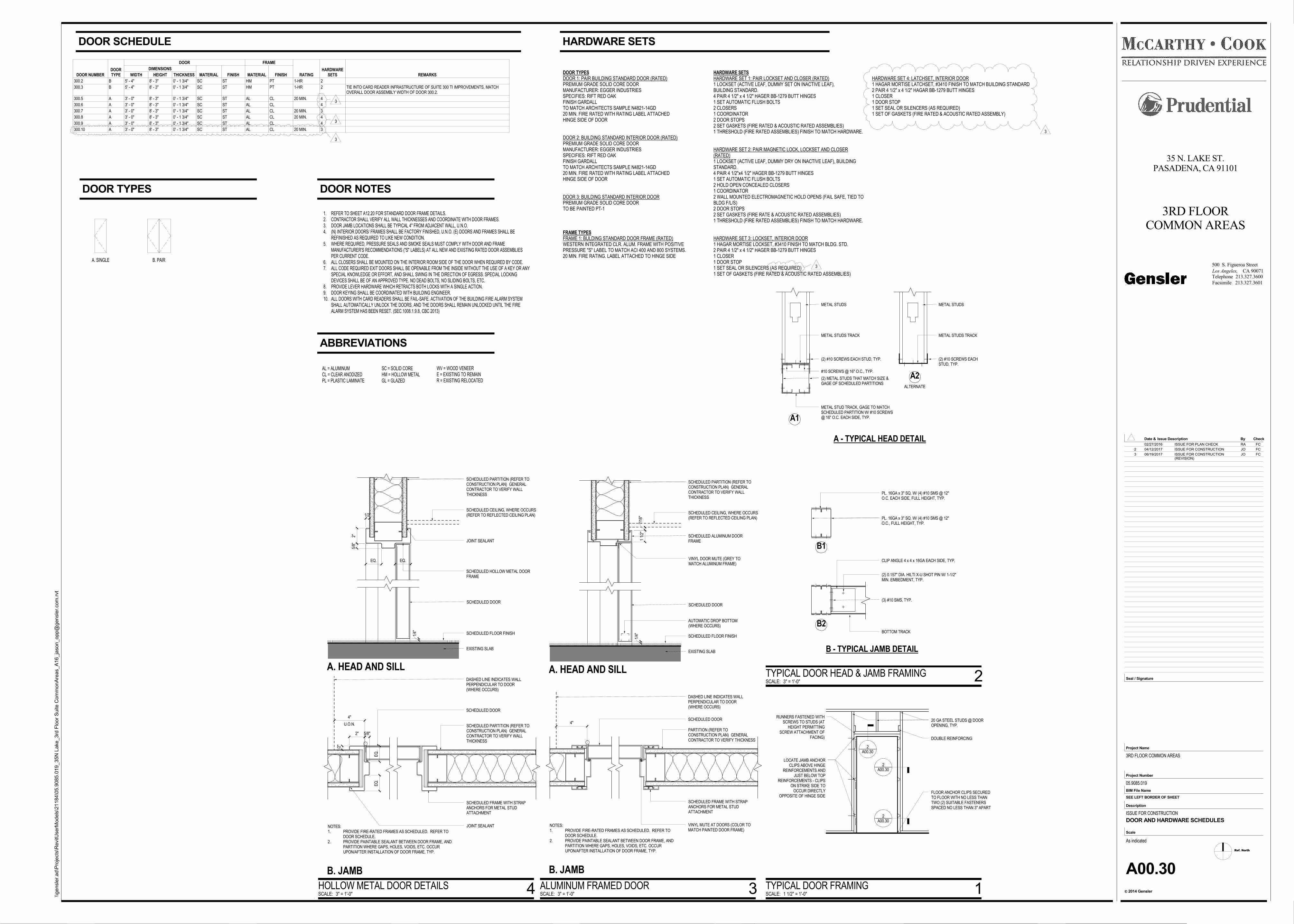
AL = ALUMINUMCL = CLEAR ANODIZEDPL = PLASTIC LAMINATE
SC = SOLID COREHM = HOLLOW METALGL = GLAZED
WV = WOOD VENEERE = EXISTING TO REMAINR = EXISTING RELOCATED
1. REFER TO SHEET A12.20 FOR STANDARD DOOR FRAME DETAILS.2. CONTRACTOR SHALL VERIFY ALL WALL THICKNESSES AND COORDINATE WITH DOOR FRAMES.3. DOOR JAMB LOCATIONS SHALL BE TYPICAL 4" FROM ADJACENT WALL, U.N.O.4. (N) INTERIOR DOORS/ FRAMES SHALL BE FACTORY FINISHED, U.N.O. (E) DOORS AND FRAMES SHALL BE
REFINISHED AS REQUIRED TO LIKE NEW CONDITION.5. WHERE REQUIRED, PRESSURE SEALS AND SMOKE SEALS MUST COMPLY WITH DOOR AND FRAME
MANUFACTURER'S RECOMMENDATIONS ("S" LABELS) AT ALL NEW AND EXISTING RATED DOOR ASSEMBLIESPER CURRENT CODE.
6. ALL CLOSERS SHALL BE MOUNTED ON THE INTERIOR ROOM SIDE OF THE DOOR WHEN REQUIRED BY CODE.7. ALL CODE REQUIRED EXIT DOORS SHALL BE OPENABLE FROM THE INSIDE WITHOUT THE USE OF A KEY OR ANY
SPECIAL KNOWLEDGE OR EFFORT, AND SHALL SWING IN THE DIRECTION OF EGRESS. SPECIAL LOCKINGDEVICES SHALL BE OF AN APPROVED TYPE. NO DEAD BOLTS, NO SLIDING BOLTS, ETC.
8. PROVIDE LEVER HARDWARE WHICH RETRACTS BOTH LOCKS WITH A SINGLE ACTION.9. DOOR KEYING SHALL BE COORDINATED WITH BUILDING ENGINEER.10. ALL DOORS WITH CARD READERS SHALL BE FAIL-SAFE. ACTIVATION OF THE BUILDING FIRE ALARM SYSTEM
SHALL AUTOMATICALLY UNLOCK THE DOORS, AND THE DOORS SHALL REMAIN UNLOCKED UNTIL THE FIREALARM SYSTEM HAS BEEN RESET. (SEC.1008.1.9.8, CBC 2013)
A. SINGLE B. PAIR
DOOR TYPESDOOR 1: PAIR BUILDING STANDARD DOOR (RATED)PREMIUM GRADE SOLID CORE DOORMANUFACTURER: EGGER INDUSTRIESSPECIFIES: RIFT RED OAKFINISH GARDALLTO MATCH ARCHITECTS SAMPLE N4821-14GD20 MIN. FIRE RATED WITH RATING LABEL ATTACHEDHINGE SIDE OF DOOR
DOOR 2: BUILDING STANDARD INTERIOR DOOR (RATED)PREMIUM GRADE SOLID CORE DOORMANUFACTURER: EGGER INDUSTRIESSPECIFIES: RIFT RED OAKFINISH GARDALLTO MATCH ARCHITECTS SAMPLE N4821-14GD20 MIN. FIRE RATED WITH RATING LABEL ATTACHEDHINGE SIDE OF DOOR
DOOR 3: BUILDING STANDARD INTERIOR DOORPREMIUM GRADE SOLID CORE DOORTO BE PAINTED PT-1
FRAME TYPESFRAME 1: BULDING STANDARD DOOR FRAME (RATED)WESTERN INTEGRATED CLR. ALUM. FRAME WITH POSITIVEPRESSURE "S" LABEL TO MATCH ACI 400 AND 800 SYSTEMS.20 MIN. FIRE RATING. LABEL ATTACHED TO HINGE SIDE
HARDWARE SETSHARDWARE SET 1: PAIR LOCKSET AND CLOSER (RATED)1 LOCKSET (ACTIVE LEAF, DUMMY SET ON INACTIVE LEAF),BUILDING STANDARD.4 PAIR 4 1/2" x 4 1/2" HAGER BB-1279 BUTT HINGES1 SET AUTOMATIC FLUSH BOLTS2 CLOSERS1 COORDINATOR2 DOOR STOPS2 SET GASKETS (FIRE RATED & ACOUSTIC RATED ASSEMBLIES)1 THRESHOLD (FIRE RATED ASSEMBLIES) FINISH TO MATCH HARDWARE.
HARDWARE SET 2: PAIR MAGNETIC LOCK, LOCKSET AND CLOSER(RATED)1 LOCKSET (ACTIVE LEAF, DUMMY DRY ON INACTIVE LEAF), BUILDINGSTANDARD.4 PAIR 4 1/2"x4 1/2" HAGER BB-1279 BUTT HINGES1 SET AUTOMATIC FLUSH BOLTS2 HOLD OPEN CONCEALED CLOSERS1 COORDINATOR2 WALL MOUNTED ELECTROMAGNETIC HOLD OPENS (FAIL SAFE, TIED TOBLDG F/L/S)2 DOOR STOPS2 SET GASKETS (FIRE RATE & ACOUSTIC RATED ASSEMBLIES)1 THRESHOLD (FIRE RATED ASSEMBLIES) FINISH TO MATCH HARDWARE.
HARDWARE SET 3: LOCKSET, INTERIOR DOOR1 HAGAR MORTISE LOCKSET, #3410 FINISH TO MATCH BLDG. STD.2 PAIR 4 1/2" x 4 1/2" HAGER BB-1279 BUTT HINGES1 CLOSER1 DOOR STOP1 SET SEAL OR SILENCERS (AS REQUIRED)1 SET OF GASKETS (FIRE RATED & ACOUSTIC RATED ASSEMBLIES)
HARDWARE SET 4: LATCHSET, INTERIOR DOOR1 HAGAR MORTISE LATCHSET, #3410 FINISH TO MATCH BUILDING STANDARD2 PAIR 4 1/2" x 4 1/2" HAGAR BB-1279 BUTT HINGES1 CLOSER1 DOOR STOP1 SET SEAL OR SILENCERS (AS REQUIRED)1 SET OF GASKETS (FIRE RATED & ACOUSTIC RATED ASSEMBLY)
SCHEDULED PARTITION (REFER TOCONSTRUCTION PLAN) GENERALCONTRACTOR TO VERIFY WALLTHICKNESS
DASHED LINE INDICATES WALLPERPENDICULAR TO DOOR(WHERE OCCURS)
SCHEDULED DOOR
SCHEDULED FRAME WITH STRAPANCHORS FOR METAL STUDATTACHMENT
NOTES:1. PROVIDE FIRE-RATED FRAMES AS SCHEDULED. REFER TO
DOOR SCHEDULE.2. PROVIDE PAINTABLE SEALANT BETWEEN DOOR FRAME, AND
PARTITION WHERE GAPS, HOLES, VOIDS, ETC. OCCURUPON/AFTER INSTALLATION OF DOOR FRAME, TYP.
JOINT SEALANT
SCHEDULED PARTITION (REFER TOCONSTRUCTION PLAN) GENERALCONTRACTOR TO VERIFY WALLTHICKNESS
SCHEDULED HOLLOW METAL DOORFRAME
EXISTING SLAB
SCHEDULED CEILING, WHERE OCCURS(REFER TO REFLECTED CEILING PLAN)
1/4" SCHEDULED FLOOR FINISH
SCHEDULED DOOR
A. HEAD AND SILL
B. JAMB
JOINT SEALANT
2"
1/2"
5/8"
EQ. EQ.
2" 5/8"
1/2"
EQ
.E
Q.
U.O.N.
4"
PARTITION (REFER TOCONSTRUCTION PLAN) GENERALCONTRACTOR TO VERIFY THICKNESS
DASHED LINE INDICATES WALLPERPENDICULAR TO DOOR(WHERE OCCURS)
SCHEDULED DOOR
SCHEDULED FRAME WITH STRAPANCHORS FOR METAL STUDATTACHMENT
4"
NOTES:1. PROVIDE FIRE-RATED FRAMES AS SCHEDULED. REFER TO
DOOR SCHEDULE.2. PROVIDE PAINTABLE SEALANT BETWEEN DOOR FRAME, AND
PARTITION WHERE GAPS, HOLES, VOIDS, ETC. OCCURUPON/AFTER INSTALLATION OF DOOR FRAME, TYP.
VINYL MUTE AT DOORS (COLOR TOMATCH PAINTED DOOR FRAME)
SCHEDULED PARTITION (REFER TOCONSTRUCTION PLAN) GENERALCONTRACTOR TO VERIFY WALLTHICKNESS
SCHEDULED ALUMINUM DOORFRAME
VINYL DOOR MUTE (GREY TOMATCH ALUMINUM FRAME)
EXISTING SLAB
SCHEDULED CEILING, WHERE OCCURS(REFER TO REFLECTED CEILING PLAN)
1/4" SCHEDULED FLOOR FINISH
1 1/
2"7/
16"
SCHEDULED DOOR
A. HEAD AND SILL
B. JAMB
AUTOMATIC DROP BOTTOM(WHERE OCCURS)
20 GA STEEL STUDS @ DOOROPENING, TYP.
DOUBLE REINFORCING
FLOOR ANCHOR CLIPS SECUREDTO FLOOR WITH NO LESS THANTWO (2) SUITABLE FASTENERSSPACED NO LESS THAN 3" APART
RUNNERS FASTENED WITHSCREWS TO STUDS (AT
HEIGHT PERMITTINGSCREW ATTACHMENT OF
FACING)
LOCATE JAMB ANCHORCLIPS ABOVE HINGE
REINFORCEMENTS ANDJUST BELOW TOP
REINFORCEMENTS - CLIPSON STRIKE SIDE TO
OCCUR DIRECTLYOPPOSITE OF HINGE SIDE
2A00.30
________________
2A00.30
________________
2A00.30
________________
METAL STUDS
METAL STUDS TRACK
(2) #10 SCREWS EACH STUD, TYP.
#10 SCREWS @ 16" O.C., TYP.
(2) METAL STUDS THAT MATCH SIZE &GAGE OF SCHEDULED PARTITIONS
METAL STUD TRACK, GAGE TO MATCHSCHEDULED PARTITION W/ #10 SCREWS@ 16" O.C. EACH SIDE, TYP.
METAL STUDS
METAL STUDS TRACK
(2) #10 SCREWS EACHSTUD, TYP.
A - TYPICAL HEAD DETAIL
A1
A2
PL. 16GA x 3" SQ. W/ (4) #10 SMS @ 12"O.C. EACH SIDE, FULL HEIGHT, TYP.
PL. 16GA x 3" SQ. W/ (4) #10 SMS @ 12"O.C., FULL HEIGHT, TYP.
CLIP ANGLE 4 x 4 x 16GA EACH SIDE, TYP.
(2) 0.157" DIA. HILTI X-U SHOT PIN W/ 1-1/2"MIN. EMBEDMENT, TYP.
(3) #10 SMS, TYP.
BOTTOM TRACK
B - TYPICAL JAMB DETAIL
ALTERNATE
B1
B2
Ref. North
CA 90071Los Angeles,
2014 Gensler
Project Number
BIM File Name
Scale
Description
c
Project Name
Seal / Signature
Check
Facsimile 213.327.3601
Telephone 213.327.3600
Date & By
500 S. Figueroa Street
Issue Description
SEE LEFT BORDER OF SHEET
\\ge
nsl
er.
ad\P
roje
cts
\RevitU
serM
od
els
\21
184
\05
.90
85.0
19
_35
N L
ake
_3rd
Flo
or
Su
ite C
om
mo
nA
reas_A
16_ja
son_o
pp@
gen
sle
r.com
.rvt
As indicated
35 N. LAKE ST.PASADENA, CA 91101
3RD FLOORCOMMON AREAS
3RD FLOOR COMMON AREAS
05.9085.019
ISSUE FOR CONSTRUCTION
A00.30
DOOR AND HARDWARE SCHEDULES
DOOR NUMBERDOORTYPE
DOOR FRAME
RATINGHARDWARE
SETS REMARKS
DIMENSIONS
MATERIAL FINISH MATERIAL FINISHWIDTH HEIGHT THICKNESS
300.2 B 5' - 4" 8' - 3" 0' - 1 3/4" SC ST HM PT 1-HR 2
300.3 B 5' - 4" 8' - 3" 0' - 1 3/4" SC ST HM PT 1-HR 2 TIE INTO CARD READER INFRASTRUCTURE OF SUITE 300 TI IMPROVEMENTS, MATCHOVERALL DOOR ASSEMBLY WIDTH OF DOOR 300.2.
300.5 A 3' - 0" 8' - 3" 0' - 1 3/4" SC ST AL CL 20 MIN. 4
300.6 A 3' - 0" 8' - 3" 0' - 1 3/4" SC ST AL CL 4
300.7 A 3' - 0" 8' - 3" 0' - 1 3/4" SC ST AL CL 20 MIN. 3
300.8 A 3' - 0" 8' - 3" 0' - 1 3/4" SC ST AL CL 20 MIN. 4
300.9 A 3' - 0" 8' - 3" 0' - 1 3/4" SC ST AL CL 4
300.10 A 3' - 0" 8' - 3" 0' - 1 3/4" SC ST AL CL 20 MIN. 3
DOOR SCHEDULE
DOOR TYPES DOOR NOTES
ABBREVIATIONS
HARDWARE SETS
SCALE: 3" = 1'-0"
HOLLOW METAL DOOR DETAILS 4 SCALE: 3" = 1'-0"
ALUMINUM FRAMED DOOR 3 SCALE: 1 1/2" = 1'-0"
TYPICAL DOOR FRAMING 1
SCALE: 3" = 1'-0"
TYPICAL DOOR HEAD & JAMB FRAMING 2
02/27/2016 ISSUE FOR PLAN CHECK RA FC
2 04/12/2017 ISSUE FOR CONSTRUCTION JO FC
3 06/19/2017 ISSUE FOR CONSTRUCTION(REVISION)
JO FC
3
3
3
3
3
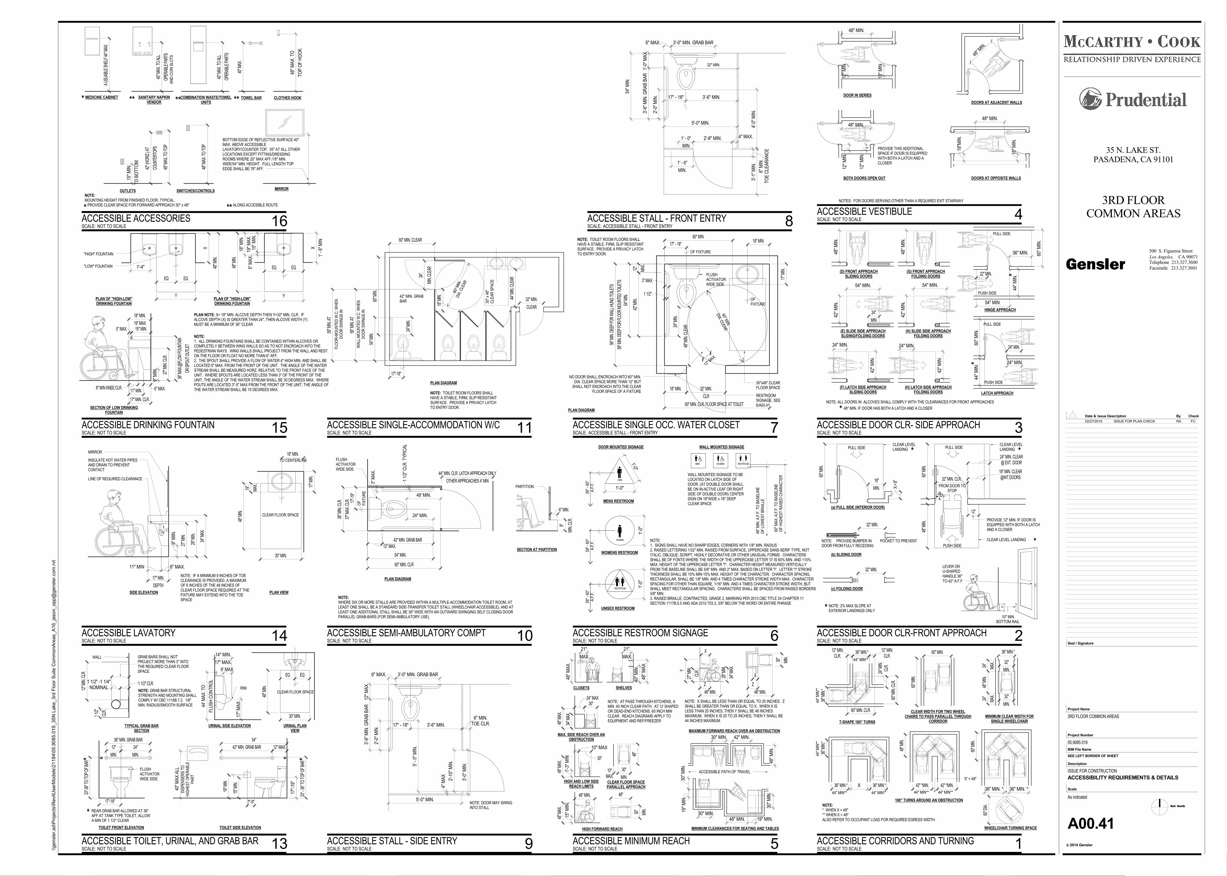
COMBINATION WASTE/TOWELUNITS
SANITARY NAPKINVENDOR
OUTLETSMIRROR
NOTE:MOUNTING HEIGHT FROM FINISHED FLOOR, TYPICAL. PROVIDE CLEAR SPACE FOR FORWARD APPROACH 30" x 48"
.
COUN
TERT
OPS
42" (
HORI
Z.) A
T
OPER
ABLE
PAR
TS
40" M
AX. T
O AL
L
OPE
RABL
E PA
RTS
40" M
AX. T
O AL
L
TOWEL BAR
40" M
AX.
CLOTHES HOOK
TOP
OF
HO
OK
48" M
AX
. TO
SWITCHES/CONTROLS
48" M
AX. T
O TO
P
TO B
OTT
OM
15"
MIN
.
BOTTOM EDGE OF REFLECTIVE SURFACE 40"MAX. ABOVE ACCESSIBLELAVATORY/COUNTER TOP. 35" AT ALL OTHERLOCATIONS EXCEPT FITTING/DRESSINGROOMS WHERE 20" MAX AFF./18" MIN.WIDE/54" MIN. HEIGHT. FULL LENGTH TOPEDGE SHALL BE 78" AFF.48
" MAX
. TO
TOP
AN
D C
OIN
SLO
TS
MEDICINE CABINET
A US
UABL
E SH
ELF
44" M
AX.
*
*
ALONG ACCESIBLE ROUTE**
** ** **
RESTROOMWOMENMEN
WALL MOUNTED SIGNAGE TO BELOCATED ON LATCH SIDE OFDOOR. (AT DOUBLE DOOR SHALLBE ON IN-ACTIVE LEAF OR RIGHTSIDE OF DOUBLE DOOR) CENTERSIGN ON 18"WIDE x 18" DEEPCLEAR SPACE
NOTE:1. SIGNS SHALL HAVE NO SHARP EDGES, CORNERS WITH 1/8" MIN. RADIUS2. RAISED LETTERING 1/32" MIN. RAISED FROM SURFACE, UPPERCASE SANS-SERIF TYPE, NOTITALIC, OBLIQUE, SCRIPT, HIGHLY DECORATIVE OR OTHER UNUSUAL FORMS. CHARACTERSSHALL BE OF FONTS WHERE THE WIDTH OF THE UPPERCASE LETTER 'O' IS 60% MIN. AND 110%MAX. HEIGHT OF THE UPPERCASE LETTER "I". CHARACTER HEIGHT MEASURED VERTICALLYFROM THE BASELINE SHALL BE 5/8" MIN. AND 2" MAX. BASED ON LETTER "I". LETTER "I" STROKETHICKNESS SHALL BE 10% MIN-15% MAX. HEIGHT OF THE CHARACTER. CHARACTER SPACING,RECTANGULAR, SHALL BE 1/8" MIN. AND 4 TIMES CHARACTER STROKE WIDTH MAX. CHARACTERSPACING FOR OTHER THAN SQUARE, 1/16" MIN. AND 4 TIMES CHARACTER STROKE WIDTH, BUTSHALL MEET RECTANGULAR SPACING. CHARACTERS SHALL BE SPACED FROM RAISED BORDERS3/8" MIN.3. RAISED BRAILLE, CONTRACTED, GRADE 2, MARKING PER 2013 CBC TITLE 24 CHAPTER 11SECTION 1117B.5.5 AND ADA 2010 703.3, 3/8" BELOW THE WORD OR ENTIRE PHRASE
UNISEX RESTROOM
WOMENS RESTROOM
MENS RESTROOM
58" -
60"
A.F
.F.
58" -
60"
A.F
.F.
58" -
60"
A.F
.F.
DOOR MOUNTED SIGNAGE WALL MOUNTED SIGNAGE
1'-0"
1'-0"
1'-0
"1'
-0"
.
48" M
IN. A
.F.F
. TO
BA
SE
LIN
EO
F LO
WE
ST
BR
AIL
LE
MEN
WOMEN
RESTROOM
.
60" M
AX
. A.F
.F. T
O B
AS
ELI
NE
OF
HIG
HE
ST
RA
ISE
D C
HA
RA
CTE
R
PLAN NOTE: X= 18" MIN. ALCOVE DEPTH THEN Y=32" MIN. CLR. IFALCOVE DEPTH (X) IS GREATER THAN 24", THEN ALCOVE WIDTH (Y)MUST BE A MINIMUM OF 36" CLEAR
1'-4"
19" MAX
18" MIN.
OR S
POUT
OUT
LET
36" M
AX.@
FLOW
FOU
NTAI
N
27" M
IN. C
LR.
9" M
IN.
6" MAX.8" MIN KNEE CLR.11" MIN.
5" MAX. 15" MIN.
48" M
IN. 1'
- 6"
MIN
X
Y
5" M
AX
.15
" MIN
.19
" MA
X.
18" M
IN.
PLAN OF "HIGH-LOW"DRINKING FOUNTAIN
"HIGH" FOUNTAIN
"LOW" FOUNTAIN
NOTE:1. ALL DRINKING FOUNTAINS SHALL BE CONTAINED WITHIN ALCOVES ORCOMPLETELY BETWEEN WING WALLS SO AS TO NOT ENCROACH INTO THEPEDESTRIAN WAYS. WING WALLS SHALL PROJECT FROM THE WALL AND RESTON THE FLOOR OR FLOAT NO MORE THAN 6" AFF.2. THE SPOUT SHALL PROVIDE A FLOW OF WATER 4" HIGH MIN. AND SHALL BELOCATED 5" MAX. FROM THE FRONT OF THE UNIT. THE ANGLE OF THE WATERSTREAM SHALL BE MEASURED HORZ. RELATIVE TO THE FRONT FACE OF THEUNIT. WHERE SPOUTS ARE LOCATED LESS THAN 3" OF THE FRONT OF THEUNIT, THE ANGLE OF THE WATER STREAM SHALL BE 30 DEGREES MAX. WHEREPOUTS ARE LOCATED 3"-5" MAX FROM THE FRONT OF THE UNIT, THE ANGLE OFTHE WATER STREAM SHALL BE 15 DEGREES MAX.
17" MIN. CLR.
Y
X
48" M
IN.
EQ EQ
EQ EQ
PLAN OF "HIGH-LOW"DRINKING FOUNTAIN
SECTION OF LOW DRINKINGFOUNTAIN
NOTE:WHERE SIX OR MORE STALLS ARE PROVIDED WITHIN A MULTIPLE-ACCOMMODATION TOILET ROOM, ATLEAST ONE SHALL BE A STANDARD SIDE-TRANSFER TOILET STALL (WHEELCHAIR ACCESSIBLE), AND ATLEAST ONE ADDITIONAL STALL SHALL BE 36" WIDE WITH AN OUTWARD SWINGING SELF CLOSING DOORPARALLEL GRAB-BARS (FOR SEMI-AMBULATORY USE).
12" MAX.42" MIN. GRAB BAR
37" M
AX. C
LR.
36" M
IN. C
LR.
54" MIN.
24" MIN.
48' MIN.
3" M
AX
.
1 1/
2" C
LR. T
YP
ICA
L
17"-1
9"
OF
FIX
TUR
E
FLUSHACTIVATORWIDE SIDE
PLAN DIAGRAM
60" MIN. CLR
OTHER APPROACHES 4' MIN
44" MIN. CLR. LATCH APPROACH ONLY
MIN
. CLR
.
9"
SECTION AT PARTITION
PARTITION
6" MIN.
30"x48" CLEARFLOOR SPACE
60" MIN
.
DIA. C
LEAR
12" MAX.
17" - 18"18" MIN.
24" M
IN.
48" M
IN. C
LEAR
17" M
IN.
18" MIN.
CLR
32" MIN.
3" MAX
1 1/2".
MAX
.
12".
42" M
IN.
54" M
IN.
60" MIN. CLR. FLOOR SPACE AT TOILET
60" MIN.
OF FIXTURE
OFFIXTURE
NO DOOR SHALL ENCROACH INTO 60" MIN.DIA. CLEAR SPACE MORE THAN 12" BUT
SHALL NOT ENCROACH INTO THE CLEARFLOOR SPACE OF A FIXTURE
NOTE: TOILET ROOM FLOORS SHALLHAVE A STABLE, FIRM, SLIP RESISTANTSURFACE. PROVIDE A PRIVACY LATCHTO ENTRY DOOR.
59" M
IN. D
EEP
FOR
FLOO
R M
OUNT
ED T
OILE
TS
56" M
IN. D
EEP
FOR
WAL
L HUN
G TO
ILETS
FLUSHACTIVATORWIDE SIDE
PLAN DIAGRAM
RESTROOMSIGNAGE. SEE6/A00.41
54"
12" MAX.42" MIN. GRAB BAR
19" M
IN
36" MIN. GRAB BAR
MIN.
12"
33"-3
6" T
O TO
P OF
BAR
17"-
19"
17"-18"
40" M
AX
ALL
DIS
PE
NS
ER
S T
OH
IGH
ES
T O
PE
RA
BLE
PA
RT
33" -
36" T
O TO
P OF
BAR
7"-9"
15" M
IN.
MIN.
24"
*
* REAR GRAB BAR ALLOWED AT 36"AFF AT TANK TYPE TOILET, ALLOWA MIN OF 1 1/2" CLEAR
TOILET SIDE ELEVATIONTOILET FRONT ELEVATION
FLUSHACTIVATORWIDE SIDE
*
17" MAX.
14" MIN.
17" M
AX
48" M
IN.
30" MIN.
6' MAX.
FLU
SH
CO
NTR
OL
44' M
AX
. TO RIM
CLEAR FLOOR SPACE
URINAL PLANVIEW
URINAL SIDE ELEVATION
EQ EQ
48"
MIN
.
(D) FRONT APPROACHSLIDING DOORS
48"
MIN
.
(G) FRONT APPROACHFOLDING DOORS
42"
MIN
.
54" MIN.
(E) SLIDE SIDE APPROACHSLIDING/FOLDING DOORS
42"
MIN
.
(H) SLIDE SIDE APPROACHFOLDING DOORS
54" MIN.
(F) LATCH SIDE APPROACHSLIDING DOORS
42"
MIN
.
24" MIN.
(H) LATCH SIDE APPROACHFOLDING DOORS
42"
MIN
.
24" MIN.
NOTE: ALL DOORS IN ALCOVES SHALL COMPLY WITH THE CLEARANCES FOR FRONT APPROACHES
MIN.
24".
54" MIN.
PUSH SIDE
44"
MIN
.
36" MIN. 60"
MIN
.
PULL SIDE
48" MIN. IF DOOR HAS BOTH A LATCH AND A CLOSER
HINGE APPROACH
PUSH SIDE
44"
MIN
.60
" M
IN.
PULL SIDE
LATCH APPROACH
24" MIN.
*
*
*
24" MIN.
22" MIN.
18"M
IN.
18"
MIN
.
48" MIN.
48" M
IN.
DOORS AT ADJACENT WALLS
DOORS AT OPPOSITE WALLS
48" MIN.
18"
MIN
.
12"
MIN
.
48" MIN.
12"
MIN
.
12"
MIN
.
PROVIDE THIS ADDITIONALSPACE IF DOOR IS EQUIPPEDWITH BOTH A LATCH AND ACLOSER
BOTH DOORS OPEN OUT
NOTES: FOR DOORS SERVING OTHER THAN A REQUIRED EXIT STAIRWAY
DOOR IN SERIES
60" M
IN.
(a) PULL SIDE (INTERIOR DOOR)
32" MIN.
NOTE: PROVIDE BUMPER IN POCKET TO PREVENTDOOR FROM FULLY RECEDING
(b) SLIDING DOOR
(c) FOLDING DOOR
32" MIN.
PULL SIDECLEAR LEVELLANDING
PUSH SIDE
CLEAR LEVEL LANDING
PROVIDE 12" MIN. IF DOOR ISEQUIPPED WITH BOTH A LATCHAND A CLOSER
NOTE: 2% MAX SLOPE ATEXTERIOR LANDINGS ONLY
48" M
IN.
60" M
IN.
12"
32" MIN. CLR. @INT.DOORS18" MIN. CLEAR
@ EXT. DOOR24" MIN. CLEAR
10" MINBOTTOM RAIL
LEVER ORU-SHAPEDHANDLE 36"TO 42" A.F.F
FROM DOOR TOSTOP90°
MIN.
18"
X >
8"
PULL SIDE
*
*
*CLEAR LEVELLANDING *
30"
MIN
.
48" MIN. 19" MIN.30" MIN.
19"
MIN
.30
" M
IN.
48"
MIN
.
30" MIN. 42" MIN.
ACCESSIBLE PATH OF TRAVEL
NOTE: X SHALL BE LESS THAN OR EQUAL TO 25 INCHES. ZSHALL BE GREATER THAN OR EQUAL TO X. WHEN X ISLESS THAN 20 INCHES, THEN Y SHALL BE 48 INCHESMAXIMUM. WHEN X IS 20 TO 25 INCHES, THEN Y SHALL BE44 INCHES MAXIMUM.
HIGH FORWARD REACH
24" MAX
34" M
AX.
48" M
AX.
30"
10" MAX
1'-3
" M
IN
48" M
AX. 30"
MAX. SIDE REACH OVER ANOBSTRUCTION
HIGH AND LOW SIDEREACH LIMITS
15"
MIN
.
48" M
AX.
48" MIN. 48"
MIN
.
30"
48" M
AX
.
MAX.
21".
MIN
.
30"
Y
X
Z
48" MIN.
X
Z
48" MIN.
MAXIMUM FORWARD REACH OVER AN OBSTRUCTION
48"
MAX.10"
MIN.
30"
CLEAR FLOOR SPACEPARALLEL APPROACH
CLOSETS
40"
MIN
.
48" M
AX
.
MAX.
21".
SHELVES
NOTE: AT PASS THROUGH KITCHENS, AMIN. 40 INCH CLEAR PATH. AT 'U' SHAPEDOR DEAD-END KITCHENS, 60 INCH MINCLEAR. REACH DIAGRAMS APPLY TOEQUIPMENT AND REF/FREEZER
CLR.
27" M
IN.
34" M
AX.
28" M
IN.
MINIMUM CLEARANCES FOR SEATING AND TABLES
T-SHAPE 180° TURNS
CLEAR WIDTH FOR TWO WHEELCHAIRS TO PASS PARALLEL THROUGH
CORRIDOR
180° TURNS AROUND AN OBSTRUCTION
WHEELCHAIR TURNING SPACE
NOTE:* WHEN X < 48"** WHEN X > 48"ALSO REFER TO OCCUPANT LOAD FOR REQUIRED EGRESS WIDTH.
44" MIN** 44" MIN** 44" MIN** 44" MIN**
44" M
IN**
60" D
IA.
42" *MIN. 42" *MIN.
48" M
IN.
36" MIN.* X 36" MIN.*
36" M
IN.*
36" M
IN.*
36" MIN.* 60" MIN.
36" MIN. * 36" MIN. *
60" M
IN.
44" M
IN**
44" MIN**CLR.
12" MIN.CLR.
12" MIN.
60" M
IN. C
LR.
CLR.
24" M
IN.
60" MIN. CLR.
'X' < 48"
60" M
IN.
36" MIN.*
MAX
.
24"
48" M
IN.
MAX
.
24"
MIN.
32"
MINIMUM CLEAR WIDTH FORSINGLE WHEELCHAIR
MIN.
32"
CLEAR FLOOR SPACE
INSULATE HOT WATER PIPESAND DRAIN TO PREVENTCONTACT
LINE OF REQUIRED CLEARANCE
18" MIN.
17" M
IN.
DEPTH
17" MIN.
11" MIN 6" MAX.
9" M
IN.
27" M
IN.
29" M
IN.
34" M
AX.
TO CENTERLINE
MAX
.
19".
48" M
IN.
30" MIN.
PLAN VIEWSIDE ELEVATION
NOTE: IF A MINIMUM 9 INCHES OF TOECLEARANCE IS PROVIDED, A MAXIMUMOF 6 INCHES OF THE 48 INCHES OFCLEAR FLOOR SPACE REQUIRED AT THEFIXTURE MAY EXTEND INTO THE TOESPACE
MIRROR
NOMINAL1 1/2" -1 1/4" 1 1/2" CLR.
WALL
TYPICAL GRAB BARSECTION
CLR.
1 1/2
"
.
GRAB BARS SHALL NOTPROJECT MORE THAN 3" INTOTHE REQUIRED CLEAR FLOORSPACE
NOTE: GRAB BAR STRUCTURALSTRENGTH AND MOUNTING SHALLCOMPLY W/ CBC 1115B.7.2. 1/8"MIN. RADIUS/SMOOTH SURFACE
12" M
IN. C
LR.
60" M
IN.
DIA
. CLE
AR
17"-18"
24" M
IN.
54" M
IN.
60" MIN. CLEAR
30" x
48"
CLE
AR
SP
AC
E
44" M
IN. C
LEAR
CLEAR
32" MIN.
MIN
. CLE
AR
34".
18" M
IN.
56" M
IN. A
T
60" M
IN.
59" M
IN. A
T
42" MIN. GRABBAR
FLO
OR
-MO
UN
TED
W.C
. WH
EN
DO
OR
SW
ING
S IN
WA
LL-M
OU
NTE
D W
.C. W
HE
ND
OO
R S
WIN
GS
IN
PLAN DIAGRAM
NOTE: TOILET ROOM FLOORS SHALLHAVE A STABLE, FIRM, SLIP RESISTANTSURFACE. PROVIDE A PRIVACY LATCHTO ENTRY DOOR.
32" MIN.
6" MAX. 3'-0" MIN. GRAB BAR
1'-0
" M
AX
.3'
-6" M
IN. G
RA
B B
AR
2'-0
" M
IN. 17" - 18" 3'-6" MIN.
5'-0" MIN.
2'-8" MIN.
4'-0
" M
IN.
3'-1
" M
IN.
54" M
IN.
MIN.
1' - 6"
MIN
1' - 0" 4" MAX.
TOE
CLE
AR
AN
CE
6" M
IN.
NOTE: DOOR MAY SWINGINTO STALL
6" MAX. 3'-0" MIN. GRAB BAR
12" M
AX
.
2'-0
" M
IN.
3'-6
" MIN
. GR
AB
BA
R
5' -
0" M
IN.
5'-0" MIN.
2'-1
0" M
IN.
3'-0
" M
IN.
3'-6" MIN.17" - 18" TOE CLR.6" MIN.
4" M
AX
Ref. North
CA 90071Los Angeles,
2014 Gensler
Project Number
BIM File Name
Scale
Description
c
Project Name
Seal / Signature
Check
Facsimile 213.327.3601
Telephone 213.327.3600
Date & By
500 S. Figueroa Street
Issue Description
SEE LEFT BORDER OF SHEET
\\ge
nsl
er.
ad\P
roje
cts
\RevitU
serM
od
els
\21
184
\05
.90
85.0
19
_35
N L
ake
_3rd
Flo
or
Su
ite C
om
mo
nA
reas_A
16_ja
son_o
pp@
gen
sle
r.com
.rvt
As indicated
35 N. LAKE ST.PASADENA, CA 91101
3RD FLOORCOMMON AREAS
3RD FLOOR COMMON AREAS
05.9085.019
ISSUE FOR CONSTRUCTION
A00.41
ACCESSIBILITY REQUIREMENTS & DETAILS
SCALE: NOT TO SCALE
ACCESSIBLE ACCESSORIES 16
SCALE: NOT TO SCALE
ACCESSIBLE RESTROOM SIGNAGE 6
SCALE: NOT TO SCALE
ACCESSIBLE DRINKING FOUNTAIN 15
SCALE: NOT TO SCALE
ACCESSIBLE SEMI-AMBULATORY COMPT 10
SCALE: ACCESSIBLE STALL - FRONT ENTRY
ACCESSIBLE SINGLE OCC. WATER CLOSET 7
SCALE: NOT TO SCALE
ACCESSIBLE TOILET, URINAL, AND GRAB BAR 13
SCALE: NOT TO SCALE
ACCESSIBLE DOOR CLR- SIDE APPROACH 3
SCALE: NOT TO SCALE
ACCESSIBLE VESTIBULE 4
SCALE: NOT TO SCALE
ACCESSIBLE DOOR CLR-FRONT APPROACH 2
SCALE: NOT TO SCALE
ACCESSIBLE MINIMUM REACH 5 SCALE: NOT TO SCALE
ACCESSIBLE CORRIDORS AND TURNING 1
SCALE: NOT TO SCALE
ACCESSIBLE LAVATORY 14
SCALE: NOT TO SCALE
ACCESSIBLE SINGLE-ACCOMMODATION W/C 11
SCALE: ACCESSIBLE STALL - FRONT ENTRY
ACCESSIBLE STALL - FRONT ENTRY 8
SCALE: NOT TO SCALE
ACCESSIBLE STALL - SIDE ENTRY 9
02/27/2016 ISSUE FOR PLAN CHECK RA FC
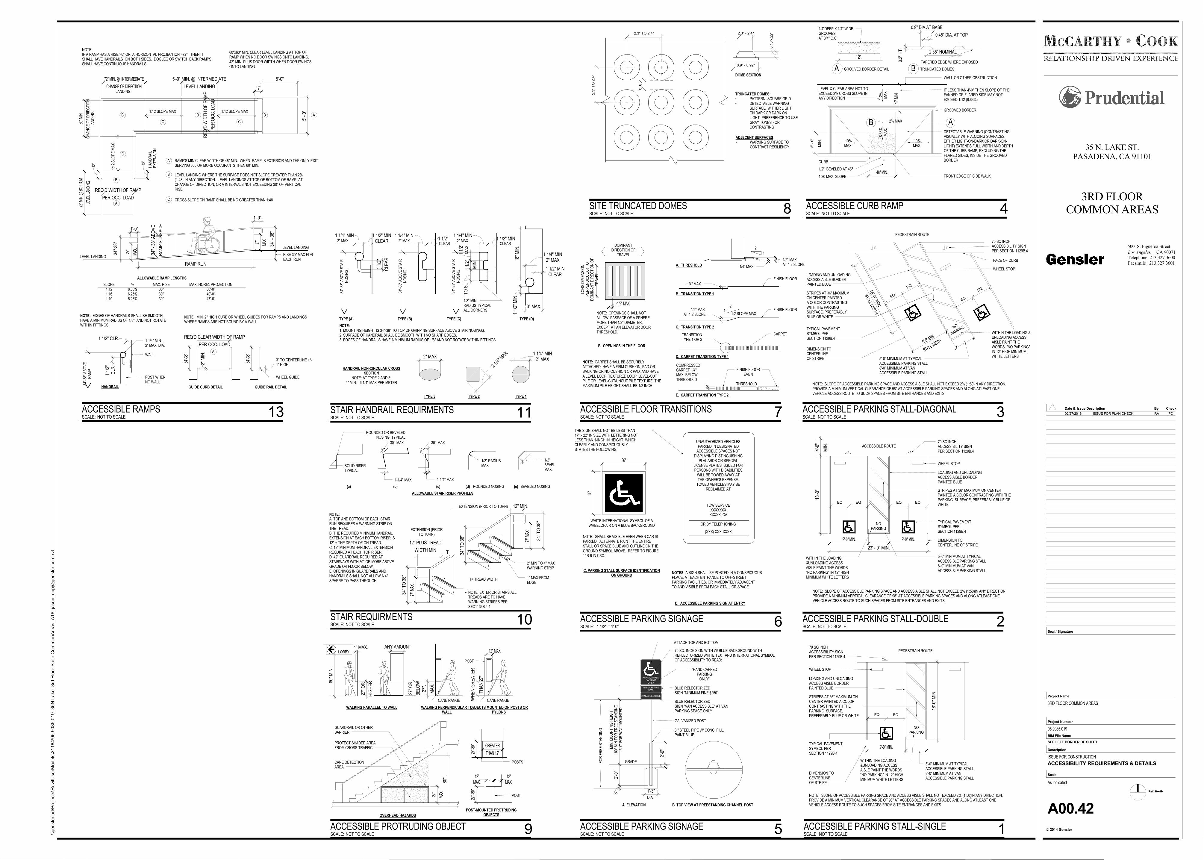
FINISH FLOOR
FINISH FLOOR
CARPET
21
1:2 SLOPE MAX
21
..
1/4" MAX.
1/2" MAX.AT 1:2 SLOPE
. .
1/4" MAX.
1/2" MAX.AT 1:2 SLOPE
FINISH FLOOREVEN
THRESHOLD.
COMPRESSEDCARPET 1/4"MAX. BELOWTHRESHOLD
NOTE: CARPET SHALL BE SECURELYATTACHED; HAVE A FIRM CUSHION, PAD ORBACKING OR NO CUSHION OR PAD; AND HAVEA LEVEL LOOP, TEXTURED LOOP, LEVEL-CUTPILE OR LEVEL-CUT/UNCUT PILE TEXTURE. THEMAXIMUM PILE HEIGHT SHALL BE 1/2 INCH
A. THRESHOLD
B. TRANSITION TYPE 1
C. TRANSITION TYPE 2
TRANSITIONTYPE 1 OR 2
D. CARPET TRANSITION TYPE 1
E. CARPET TRANSITION TYPE 2
F. OPENINGS IN THE FLOOR
DOMINANTDIRECTION OF
TRAVEL
.
1/2" MAX.
LON
G D
IME
NS
ION
PE
RP
EN
DIC
ULA
R T
OD
OM
INA
NT
DIR
EC
TIO
N O
FTR
AV
EL
NOTE: OPENINGS SHALL NOTALLOW PASSAGE OF A SPHEREMORE THAN 1/2" DIAMETER,EXCEPT AT AN ELEVATOR DOORTHRESHOLD.
FRONT EDGE OF SIDE WALK
CURB
1/2", BEVELED AT 45°
GROOVED BORDER
WALL OR OTHER OBSTRUCTION
A
10%MAX.
8.33
%M
AX
.2% MA
X.
10%MAX.
48" M
IN.
48" MIN.
1/4"DEEP X 1/4" WIDEGROOVESAT 3/4" O.C.
12".
GROOVED BORDER DETAILA
2.35" NOMINAL
TRUNCATED DOMESB
0.2"
HT
0.45" DIA. AT TOP
0.9" DIA.AT BASE
IF LESS THAN 4'-0" THEN SLOPE OF THEFANNED OR FLARED SIDE MAY NOTEXCEED 1:12 (8.88%)
B . 2% MAX
. .
DETECTABLE WARNING (CONTRASTINGVISUALLY WITH ADJOING SURFACES,EITHER LIGHT-ON-DARK OR DARK-ON-LIGHT) EXTENDS FULL WIDTH AND DEPTHOF THE CURB RAMP, EXCLUDING THEFLARED SIDES, INSIDE THE GROOVEDBORDER
.LEVEL & CLEAR AREA NOT TOEXCEED 2% CROSS SLOPE INANY DIRECTION
TAPERED EDGE WHERE EXPOSED
.
1:20 MAX. SLOPE
MIN
.
3' -
0"
NOTE:A. TOP AND BOTTOM OF EACH STAIRRUN REQUIRES A WARNING STRIP ONTHE TREAD.B. THE REQUIRED MINIMUM HANDRAILEXTENSION AT EACH BOTTOM RISER IS12" + THE DEPTH OF ON TREAD.C. 12" MINIMUM HANDRAIL EXTENSIONREQUIRED AT EACH TOP RISER.D. 42" GUARDRAIL REQUIRED ATSTAIRWAYS WITH 30" OR MORE ABOVEGRADE OR FLOOR BELOW.E. OPENINGS IN GUARDRAILS ANDHANDRAILS SHALL NOT ALLOW A 4"SPHERE TO PASS THROUGH.
SOLID RISERTYPICAL
ROUNDED OR BEVELEDNOSING, TYPICAL
(a) (b) (c)
1-1/4" MAX
30° MAX
1-1/4" MAX
30° MAX
(d) (e)ROUNDED NOSING BEVELED NOSING
1/2" RADIUSMAX.
1/2"BEVELMAX.
WIDTH MIN
12" PLUS TREAD
T
34" T
O 3
8" T= TREAD WIDTH*
*
*
* NOTE :EXTERIOR STAIRS ALLTREADS ARE TO HAVEWARNING STRIPES PERSEC1133B.4.4
1" MAX FROMEDGE
2" MIN TO 4" MAXWARNING STRIP
34" T
O 3
8"
12" MIN.
34" T
O 3
8"
EXTENSION (PRIORTO TURN)
EXTENSION (PRIOR TO TURN)
27" M
AX.
27" M
AX.
ALLOWABLE STAIR RISER PROFILES
NOTE: MIN. 2" HIGH CURB OR WHEEL GUIDES FOR RAMPS AND LANDINGSWHERE RAMPS ARE NOT BOUND BY A WALL
ALLOWABLE RAMP LENGTHS
SLOPE1:121:161:19
%8.33%6.25%5.26%
MAX. RISE30"30"30"
MAX. HORIZ. PROJECTION30'-0"40'-0"47'-6"
60"x60" MIN. CLEAR LEVEL LANDING AT TOP OFRAMP WHEN NO DOOR SWINGS ONTO LANDING.42" MIN. PLUS DOOR WIDTH WHEN DOOR SWINGSONTO LANDING
NOTE:IF A RAMP HAS A RISE >6" OR A HORIZONTAL PROJECTION >72", THEN ITSHALL HAVE HANDRAILS ON BOTH SIDES. DOGLEG OR SWITCH BACK RAMPSSHALL HAVE CONTINUOUS HANDRAILS
LEVEL LANDING
LEVEL LANDING RISE 30" MAX FOREACH RUN
1:12 SLOPE MAX34
"-38
"
1'-0"
1'-0"
34"
- 38"
2" M
IN.
5'-0"
RA
MP
SU
RFA
CE
34" -
38"
AB
OV
E
12"
1:12 SLOPE MAX1:
12 S
LOP
E M
AX
LEVEL LANDING
5'-0" MIN. @ INTERMEDIATE
CHANGE OF DIRECTION
72" MIN. @ INTERMEDIATE
LEVE
L LAN
DING
72" M
IN. @
BOT
TOM
.
PER OCC. LOAD
REQ'D CLEAR WIDTH OF RAMP
RAMP'S MIN CLEAR WIDTH OF 48" MIN. WHEN RAMP IS EXTERIOR AND THE ONLY EXITSERVING 300 OR MORE OCCUPANTS THEN 60" MIN.
A
A
PER OCC. LOAD
REQ'D WIDTH OF RAMP
A
B LEVEL LANDING WHERE THE SURFACE DOES NOT SLOPE GREATER THAN 2%(1:48) IN ANY DIRECTION. LEVEL LANDINGS AT TOP OF BOTTOM OF RAMP, ATCHANGE OF DIRECTION, OR A INTERVALS NOT EXCEEDING 30" OF VERTICALRISE
B B B
B
C CROSS SLOPE ON RAMP SHALL BE NO GREATER THAN 1:48
C C
C
60" M
IN.
HA
ND
RA
ILE
XTE
NS
ION
PE
R O
CC
. LO
AD
RE
Q'D
WID
TH O
F R
AM
P
WHEEL GUIDE
LANDINGC
HA
NG
E O
F D
RIE
CTI
ON
LAN
DIN
G12"
12"
RAMP RUN
A
GUIDE CURB DETAIL GUIDE RAIL DETAIL
3" TO CENTERLINE +/-1" HIGH
34"-3
8"
34"-3
8"
.
MAX
.
27"
MAX
.
27"
5' -
0"
HANDRAIL
1 1/4" MIN. -2" MAX. DIA.
34"-
38" A
BO
VE
RA
MP
1 1/2" CLR.
WALL
POST WHENNO WALL
CLR
1 1/
2"
NOTE: EDGES OF HANDRAILS SHALL BE SMOOTH,HAVE A MINIMUM RADIUS OF 1/8", AND NOT ROTATEWITHIN FITTINGS NOTE:
1. MOUNTING HEIGHT IS 34"-38" TO TOP OF GRIPPING SURFACE ABOVE STAIR NOSINGS.2. SURFACE OF HANDRAIL SHALL BE SMOOTH WITH NO SHARP EDGES.3. EDGES OF HANDRAILS HAVE A MINIMUM RADIUS OF 1/8" AND NOT ROTATE WITHIN FITTINGS
CLEAR1 1/2" MIN
1 1/
2" M
IN
3" MAX.
18"
MIN
.
MA
X1
1/2"
TO S
UIT
MIN
1 1/
2"
2" MAX1 1/4" MIN
2 1/4"
MAX
2" MAX
HANDRAIL NON-CIRCULAR CROSSSECTION
NOTE: AT TYPE 2 AND 3:4" MIN. - 6 1/4" MAX PERIMETER
TYPE (A)
34"-
38" A
BO
VE
STA
IRN
OS
ING
CLEAR1 1/2" MIN1 1/4" MIN -
34"-
38" A
BO
VE
STA
IRN
OS
ING
34"-
38" A
BO
VE
STA
IRN
OS
ING
2" MAX.1 1/4" MIN -
2" MAX. 1 1/2"CLEAR
1 1/4" MIN -2" MAX. 1 1/2" MIN
CLEAR
2" MAX1 1/4" MIN
CLE
AR
1 1/
2"
1/8" MIN.RADIUS TYPICALALL CORNERS
TYPE 1TYPE 2TYPE 3
TYPE (B) TYPE (C) TYPE (D)
NOPARKING
70 SQ INCHACCESSIBILITY SIGNPER SECTION 1129B.4
WHEEL STOP
WITHIN THE LOADING&UNLOADING ACCESSAISLE PAINT THE WORDS"NO PARKING" IN 12" HIGHMINIMUM WHITE LETTERS
5'-0" MINIMUM AT TYPICALACCESSIBLE PARKING STALL8'-0" MINIMUM AT VANACCESSIBLE PARKING STALL
LOADING AND UNLOADINGACCESS AISLE BORDERPAINTED BLUE
STRIPES AT 36" MAXIMUM ON CENTERPAINTED A COLOR CONTRASTING WITH THEPARKING SURFACE, PREFERABLY BLUE ORWHITE
TYPICAL PAVEMENTSYMBOL PERSECTION 1129B.4
DIMENSION TOCENTERLINE OF STRIPE
18'-0
"
ACCESSIBLE ROUTE
NOTE: SLOPE OF ACCESSIBLE PARKING SPACE AND ACCESS AISLE SHALL NOT EXCEED 2% (1:50)IN ANY DIRECTION.PROVIDE A MINIMUM VERTICAL CLEARANCE OF 98" AT ACCESSIBLE PARKING SPACES AND ALONG ATLEAST ONEVEHICLE ACCESS ROUTE TO SUCH SPACES FROM SITE ENTRANCES AND EXITS
9'-0" MIN. 9'-0" MIN.
MIN
.
4'-0
"
23' - 0" MIN.
EQ EQ EQ EQ
UNAUTHORIZED VEHICLESPARKED IN DESIGNATED
ACCESSIBLE SPACES NOTDISPLAYING DISTINGUISHING
PLACARDS OR SPECIALLICENSE PLATES ISSUED FORPERSONS WITH DISABILITIES
WILL BE TOWED AWAY ATTHE OWNER'S EXPENSE.
TOWED VEHICLES MAY BERECLAIMED AT
OR BY TELEPHONING
THE SIGN SHALL NOT BE LESS THAN17" x 22" IN SIZE WITH LETTERING NOTLESS THAN 1-INCH IN HEIGHT. WHICHCLEARLY AND CONSPICUOUSLYSTATES THE FOLLOWING:
NOTES: A SIGN SHALL BE POSTED IN A CONSPICUOUSPLACE, AT EACH ENTRANCE TO OFF-STREETPARKING FACILITIES, OR IMMEDIATELY ADJACENTTO AND VISIBLE FROM EACH STALL OR SPACE
D. ACCESSIBLE PARKING SIGN AT ENTRY
TOW SERVICEXXXXXXX
XXXXX, CA
(XXX) XXX-XXXX
NOPARKING
70 SQ INCHACCESSIBILITY SIGNPER SECTION 1129B.4
WHEEL STOP
LOADING AND UNLOADINGACCESS AISLE BORDERPAINTED BLUE
STRIPES AT 36" MAXIMUM ONCENTER PAINTED A COLORCONTRASTING WITH THEPARKING SURFACE,PREFERABLY BLUE OR WHITE
TYPICAL PAVEMENTSYMBOL PERSECTION 1129B.4
DIMENSION TOCENTERLINEOF STRIPE
PEDESTRAIN ROUTE
WITHIN THE LOADING&UNLOADING ACCESSAISLE PAINT THE WORDS"NO PARKING" IN 12" HIGHMINIMUM WHITE LETTERS
5'-0" MINIMUM AT TYPICALACCESSIBLE PARKING STALL8'-0" MINIMUM AT VANACCESSIBLE PARKING STALL
18'-0
" MIN
NOTE: SLOPE OF ACCESSIBLE PARKING SPACE AND ACCESS AISLE SHALL NOT EXCEED 2% (1:50)IN ANY DIRECTION.PROVIDE A MINIMUM VERTICAL CLEARANCE OF 98" AT ACCESSIBLE PARKING SPACES AND ALONG ATLEAST ONEVEHICLE ACCESS ROUTE TO SUCH SPACES FROM SITE ENTRANCES AND EXITS
9'-0" MIN. .
EQ EQ
HANDICAPPEDPARKING
ONLY
MINIMUM FINE$250
DIA
3"2'
-0"
GRADE
MIN
. MO
UN
TIN
G H
EIG
HT
80" M
IN F
OR
FR
EE
STA
ND
ING
3'-0
" FO
R W
ALL
MO
UN
TED
2'-0
"
FOR
FR
EE
STA
ND
ING
1'-3"
3 " STEEL PIPE W/ CONC. FILL.PAINT BLUE
GALVANIZED POST
BLUE RELECTORIZEDSIGN "MINIMUM FINE $250"
"HANDICAPPEDPARKING
ONLY"
70 SQ. INCH SIGN WITH W/ BLUE BACKGROUND WITHREFLECTORIZED WHITE TEXT AND INTERNATIONAL SYMBOLOF ACCESSIBILITY TO READ:
ATTACH TOP AND BOTTOM
A. ELEVATION B. TOP VIEW AT FREESTANDING CHANNEL POST
VAN ACCESSIBLE
BLUE RELECTORIZEDSIGN "VAN ACCESSIBLE" AT VANPARKING SPACE ONLY
.
4"
NO
PARKING
70 SQ INCHACCESSIBILITY SIGNPER SECTION 1129B.4
FACE OF CURB
WHEEL STOP
WITHIN THE LOADING &UNLOADING ACCESSAISLE PAINT THEWORDS "NO PARKING"IN 12" HIGH MINIMUMWHITE LETTERS
5'-0" MINIMUM AT TYPICALACCESSIBLE PARKING STALL8'-0" MINIMUM AT VANACCESSIBLE PARKING STALL
LOADING AND UNLOADINGACCESS AISLE BORDERPAINTED BLUE
STRIPES AT 36" MAXIMUMON CENTER PAINTEDA COLOR CONTRASTINGWITH THE PARKINGSURFACE, PREFERABLYBLUE OR WHITE
TYPICAL PAVEMENTSYMBOL PERSECTION 1129B.4
DIMENSION TOCENTERLINEOF STRIPE
NOTE: SLOPE OF ACCESSIBLE PARKING SPACE AND ACCESS AISLE SHALL NOT EXCEED 2% (1:50)IN ANY DIRECTION.PROVIDE A MINIMUM VERTICAL CLEARANCE OF 98" AT ACCESSIBLE PARKING SPACES AND ALONG ATLEAST ONEVEHICLE ACCESS ROUTE TO SUCH SPACES FROM SITE ENTRANCES AND EXITS
18'-0" MIN
STALL DEPTH
PEDESTRAIN ROUTE
.
STALL WIDTH9'-0" MIN.
EQ
EQ
EQ
EQ
36"
36"
WHITE INTERNATIONAL SYMBOL OF AWHEELCHAIR ON A BLUE BACKGROUND
C. PARKING STALL SURFACE IDENTIFICATIONON GROUND
NOTE: SHALL BE VISIBLE EVEN WHEN CAR ISPARKED. ALTERNATE PAINT THE ENTIRESTALL OR SPACE BLUE AND OUTLINE ON THEGROUND SYMBOL ABOVE. REFER TO FIGURE11B-6 IN CBC.
HIG
HE
R
27" O
R
4" MAX.LOBBY
80"
MIN
.
BE
LOW
27" O
R
ANY AMOUNT
CANE RANGE
MA
X.
27".
WALKING PERPENDICULAR TOWALL
WALKING PARALLEL TO WALL
PROTECT SHADED AREAFROM CROSS-TRAFFIC
CANE DETECTIONAREA
MAX
.
27"
80"
.
CANE RANGE
THA
N 2
7"
WH
EN
GR
EA
TER
OBJECTS MOUNTED ON POSTS ORPYLONS
12" MAX.
POST
MAX.12"
MAX.12"
27" -
80"
27"-8
0"
THAN 12"
GREATER
POST
POSTS
POST-MOUNTED PROTRUDINGOBJECTSOVERHEAD HAZARDS
GUARDRAIL OR OTHERBARRIER
DOME SECTION
TRUNCATED DOMES:• PATTERN -SQUARE GRID• DETECTABLE WARNING
SURFACE, WITHER LIGHTON DARK OR DARK ONLIGHT, PREFERENCE TO USEGRAY TONES FORCONTRASTING
ADJECENT SURFACES• WARNING SURFACE TO
CONTRAST RESILIENCY
2.3" - 2.4"2.3" TO 2.4"
2.3
" T
O 2
.4"
0.6
5"
0.1
8"-
.22"
0.9" - 0.92"
SCALE: NOT TO SCALE
ACCESSIBLE FLOOR TRANSITIONS 7
SCALE: NOT TO SCALE
ACCESSIBLE CURB RAMP 4
SCALE: NOT TO SCALE
STAIR REQUIRMENTS 10
SCALE: NOT TO SCALE
ACCESSIBLE RAMPS 13 SCALE: NOT TO SCALE
STAIR HANDRAIL REQUIRMENTS 11
Ref. North
CA 90071Los Angeles,
2014 Gensler
Project Number
BIM File Name
Scale
Description
c
Project Name
Seal / Signature
Check
Facsimile 213.327.3601
Telephone 213.327.3600
Date & By
500 S. Figueroa Street
Issue Description
SEE LEFT BORDER OF SHEET
\\ge
nsl
er.
ad\P
roje
cts
\RevitU
serM
od
els
\21
184
\05
.90
85.0
19
_35
N L
ake
_3rd
Flo
or
Su
ite C
om
mo
nA
reas_A
16_ja
son_o
pp@
gen
sle
r.com
.rvt
As indicated
35 N. LAKE ST.PASADENA, CA 91101
3RD FLOORCOMMON AREAS
3RD FLOOR COMMON AREAS
05.9085.019
ISSUE FOR CONSTRUCTION
A00.42
ACCESSIBILITY REQUIREMENTS & DETAILS
SCALE: NOT TO SCALE
ACCESSIBLE PARKING STALL-DOUBLE 2SCALE: 1 1/2" = 1'-0"
ACCESSIBLE PARKING SIGNAGE 6
SCALE: NOT TO SCALE
ACCESSIBLE PARKING STALL-SINGLE 1SCALE: NOT TO SCALE
ACCESSIBLE PARKING SIGNAGE 5
SCALE: NOT TO SCALE
ACCESSIBLE PARKING STALL-DIAGONAL 3
SCALE: NOT TO SCALE
ACCESSIBLE PROTRUDING OBJECT 9
SCALE: NOT TO SCALE
SITE TRUNCATED DOMES 8
02/27/2016 ISSUE FOR PLAN CHECK RA FC
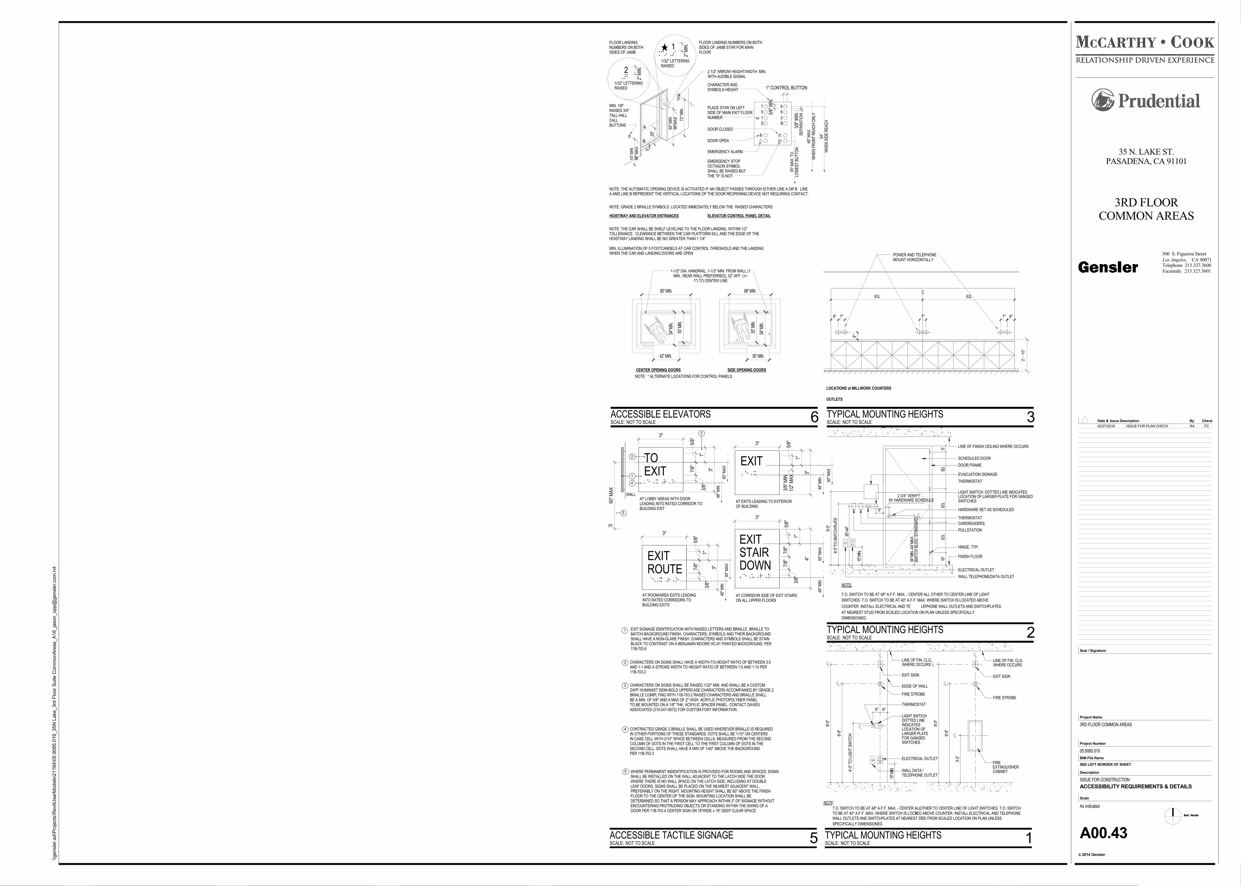
LINE OF FIN. CLG.WHERE OCCURS
EXIT SIGN
EDGE OF WALL
FIRE STROBE
THERMOSTAT
LIGHT SWTICHDOTTED LINEINDICATESLOCATION OFLARGER PLATEFOR GANGEDSWITCHES
ELECTRICAL OUTLET
WALL DATA /TELEPHONE OUTLET
LINE OF FIN. CLG.WHERE OCCURS
EXIT SIGN
FIRE STROBE
FIREEXTINGUISHERCABINET
NOTE:
T.O. SWITCH TO BE AT 48" A.F.F. MAX. - CENTER ALLOTHER TO CENTER LINE OF LIGHT SWITCHES. T.O. SWITCHTO BE AT 40" A.F.F. MAX. WHERE SWITCH IS LOCATED ABOVE COUNTER. INSTALL ELECTRICAL AND TELEPHONEWALL OUTLETS AND SWITCHPLATES AT NEAREST STUD FROM SCALED LOCATION ON PLAN UNLESS
SPECIFICALLY DIMENSIONED.8'
-0"
6 '-8
"
6" 6"
8'-0
"
6 '-8
"
3 '-2
"
15"M
IN.
4'-0
" TO
LIG
HT
SW
ITC
H
LINE OF FINISH CEILING WHERE OCCURS
HINGE, TYP.
SCHEDULED DOOR
LIGHT SWITCH. DOTTED LINE INDICATESLOCATION OF LARGER PLATE FOR GANGEDSWITCHES
FINISH FLOOR
DOOR FRAME
THERMOSTAT
HARDWARE SET AS SCHEDULED
ELECTRICAL OUTLET
WALL TELEPHONE/DATA OUTLET
NOTE:
T.O. SWITCH TO BE AT 48" A.F.F. MAX. - CENTER ALL OTHER TO CENTER LINE OF LIGHT
SWITCHES. T.O. SWITCH TO BE AT 40" A.F.F. MAX. WHERE SWITCH IS LOCATED ABOVE
COUNTER. INSTALL ELECTRICAL AND TE LEPHONE WALL OUTLETS AND SWITCHPLATES
AT NEAREST STUD FROM SCALED LOCATION ON PLAN UNLESS SPECIFICALLY
DIMENSIONED.
THERMOSTAT
EVACUATION SIGNAGE
CARDREADERS
PULLSTATION5'-0
"
4'-0 "
T.O .
S WIT
CH
PLAT
E
30"-
44"
15"M
IN.
3 4"M
IN.-4
4"M
AX
.
6"
W/ HARDWARE SCHEDULE2 3/4" VERIFY
5"EQ
.EQ
.E
Q.
10"
(MA
TCH
BLD
G. S
TAN
DA
RD
)
LOCATIONS at MILLWORK COUNTERS
OUTLETS
POWER AND TELEPHONEMOUNT HORIZONTALLY
7"
EQ EQ
8"
8" 7" 7" 8"
2' -
10"
3"
3"
1"
5/8"
1/2"
MA
X3/
8" M
IN
EXIT
3"
3"
1"
5/8"
EXIT 7/8"
3/8"
3
2 TO1
4
FF
5
WALL
60" M
AX
3"
3"
1"
5/8"
ROUTE 7/8"
3/8"
EXIT
EXIT 1"
3"
4"
5/8"
7/8"
7/8"
3/8"
STAIRDOWN
AT EXITS LEADING TO EXTERIOROF BUILDING
AT LOBBY AREAS WITH DOORLEADING INTO RATED CORRIDOR TOBUILDING EXIT
AT ROOM/AREA EXITS LEADINGINTO RATED CORRIDORS TOBUILDING EXITS
AT CORRIDOR SIDE OF EXIT STAIRSON ALL UPPER FLOORS
EXIT SIGNAGE IDENTIFICATION WITH RASIED LETTERS AND BRAILLE. BRAILLE TOMATCH BACKGROUND FINISH. CHARACTERS, SYMBOLS AND THEIR BACKGROUNDSHALL HAVE A NON-GLARE FINISH. CHARACTERS AND SYMBOLS SHALL BE STAINBLACK TO CONTRAST ON A BENJAMIN MOORE HC-81 PAINTED BACKGROUND, PER11B-703.6
CHARACTERS ON SIGNS SHALL HAVE A WIDTH-TO-HEIGHT RATIO OF BETWEEN 3:5AND 1:1 AND A STROKE WIDTH TO HEIGHT RATIO OF BETWEEN 1:5 AND 1:10 PER11B-703.2
CHARACTERS ON SIGNS SHALL BE RAISED 1/32" MIN. AND SHALL BE A CUSTOMZAPF HUMANIST DEMI-BOLD UPPERCASE CHARACTERS ACCOMPANIED BY GRADE 2BRAILLE COMPLYING WITH 11B-703.2 RAISED CHARACTERS AND BRAILLE SHALLBE A MIN. OF 5/8" AND A MAX OF 2" HIGH. ACRYLIC PHOTOPOLYMER PANELTO BE MOUNTED ON A 1/8" THK. ACRYLIC SPACER PANEL. CONTACT DAVIESASSOCIATES (310-247-9572) FOR CUSTOM FONT INFORMATION.
CONTRACTED GRADE 2 BRAILLE SHALL BE USED WHEREVER BRAILLE IS REQUIREDIN OTHER PORTIONS OF THESE STANDARDS. DOTS SHALL BE 1/10" ON CENTERSIN CASE CELL WITH 2/10" SPACE BETWEEN CELLS, MEASURED FROM THE SECONDCOLUMN OF DOTS IN THE FIRST CELL TO THE FIRST COLUMN OF DOTS IN THESECOND CELL. DOTS SHALL HAVE A MIN OF 1/40" ABOVE THE BACKGROUNDPER 11B-703.3
WHERE PERMANENT INDENTIFICATION IS PROVIDED FOR ROOMS AND SPACES, SIGNSSHALL BE INSTALLED ON THE WALL ADJACENT TO THE LATCH SIDE THE DOOR.WHERE THERE IS NO WALL SPACE ON THE LATCH SIDE, INCLUDING AT DOUBLELEAF DOORS, SIGNS SHALL BE PLACED ON THE NEAREST ADJACENT WALL,PREFERABLY ON THE RIGHT. MOUNTING HEIGHT SHALL BE 60" ABOVE THE FINISHFLOOR TO THE CENTER OF THE SIGN. MOUNTING LOCATION SHALL BEDETERMINED SO THAT A PERSON MAY APPROACH WITHIN 3" OF SIGNAGE WITHOUTENCOUNTERING PROTRUDING OBJECTS OR STANDING WITHIN THE SWING OF ADOOR PER 11B-703.4 CENTER SIGN ON 18"WIDE x 18" DEEP CLEAR SPACE
2
3
4
5
.
48" M
IN
.
48" M
IN
.
48" M
IN
.
48" M
IN
.
60" M
AX
.
60" M
AX
.
60" M
AX
.
60" M
AX
1
72" M
IN.
60" M
IN98
"MA
X
A
B
29"
5"
NOTE: THE AUTOMATIC OPENING DEVICE IS ACTIVATED IF AN OBJECT PASSES THROUGH EITHER LINE A OR B. LINEA AND LINE B REPRESENT THE VERTICAL LOCATIONS OF THE DOOR REOPENING DEVICE NOT REQUIRING CONTACT.
15" M
IN48
" MA
X
CENTER OPENING DOORS SIDE OPENING DOORS
1-1/2" DIA. HANDRAIL, 1-1/2" MIN. FROM WALL (1MIN., REAR WALL PREFERRED), 32" AFF. (+/-
1") TO CENTER LINE
80" MIN.
54" M
IN.
42" MIN.
50" M
IN.
68" MIN.
54" M
IN.
50" M
IN.
36" MIN.
2...... 2" M
IN.
1/32" LETTERINGRAISED
7
5
1
S
8
6
2
B
1" CONTROL BUTTON
5/8"
MIN
.
CHARACTER ANDSYMBOLS HEIGHT
3/8"
MIN
. .
48" M
AX
.W
HE
N F
RO
NT
RE
AC
H O
NLY
54"
WH
EN
SID
E R
EA
CH
.
35" M
AX
. TO
LOW
ES
T B
UTT
ON
PLACE STAR ON LEFTSIDE OF MAIN EXIT FLOORNUMBER
DOOR OPEN
DOOR CLOSED
EMERGENCY ALARM
EMERGENCY STOPOCTAGON SYMBOLSHALL BE RAISED BUTTHE "X" IS NOT
NOTE: GRADE 2 BRAILLE SYMBOLS LOCATED IMMEDIATELY BELOW THE RAISED CHARACTERS
2 1/2" ARROW HEIGHT/WIDTH MIN.WITH AUDIBLE SIGNAL
*
*
NOTE: * ALTERNATE LOCATIONS FOR CONTROL PANELS
FLOOR LANDINGNUMBERS ON BOTHSIDES OF JAMB
SE
PA
RA
TIO
N
ELEVATOR CONTROL PANEL DETAILHOISTWAY AND ELEVATOR ENTRANCES
MIN. 1/8"RAISED 3/4"TALL HALLCALLBUTTONS
NOTE: THE CAR SHALL BE SHELF LEVELING TO THE FLOOR LANDING, WITHIN 1/2"TOLLERANCE. CLEARANCE BETWEEN THE CAR PLATFORM SILL AND THE EDGE OF THEHOISTWAY LANDING SHALL BE NO GREATER THAN 1 1/4"
MIN. ILLUMINATION OF 5 FOOTCANDELS AT CAR CONTROL THRESHOLD AND THE LANDINGWHEN THE CAR AND LANDING DOORS ARE OPEN
.... 2" M
IN.
1/32" LETTERINGRAISED
1. . ....
FLOOR LANDING NUMBERS ON BOTHSIDES OF JAMB STAR FOR MAINFLOOR
Ref. North
CA 90071Los Angeles,
2014 Gensler
Project Number
BIM File Name
Scale
Description
c
Project Name
Seal / Signature
Check
Facsimile 213.327.3601
Telephone 213.327.3600
Date & By
500 S. Figueroa Street
Issue Description
SEE LEFT BORDER OF SHEET
\\ge
nsl
er.
ad\P
roje
cts
\RevitU
serM
od
els
\21
184
\05
.90
85.0
19
_35
N L
ake
_3rd
Flo
or
Su
ite C
om
mo
nA
reas_A
16_ja
son_o
pp@
gen
sle
r.com
.rvt
As indicated
35 N. LAKE ST.PASADENA, CA 91101
3RD FLOORCOMMON AREAS
3RD FLOOR COMMON AREAS
05.9085.019
ISSUE FOR CONSTRUCTION
A00.43
ACCESSIBILITY REQUIREMENTS & DETAILS
SCALE: NOT TO SCALE
TYPICAL MOUNTING HEIGHTS 1
SCALE: NOT TO SCALE
TYPICAL MOUNTING HEIGHTS 2
SCALE: NOT TO SCALE
TYPICAL MOUNTING HEIGHTS 3
SCALE: NOT TO SCALE
ACCESSIBLE TACTILE SIGNAGE 5
SCALE: NOT TO SCALE
ACCESSIBLE ELEVATORS 602/27/2016 ISSUE FOR PLAN CHECK RA FC
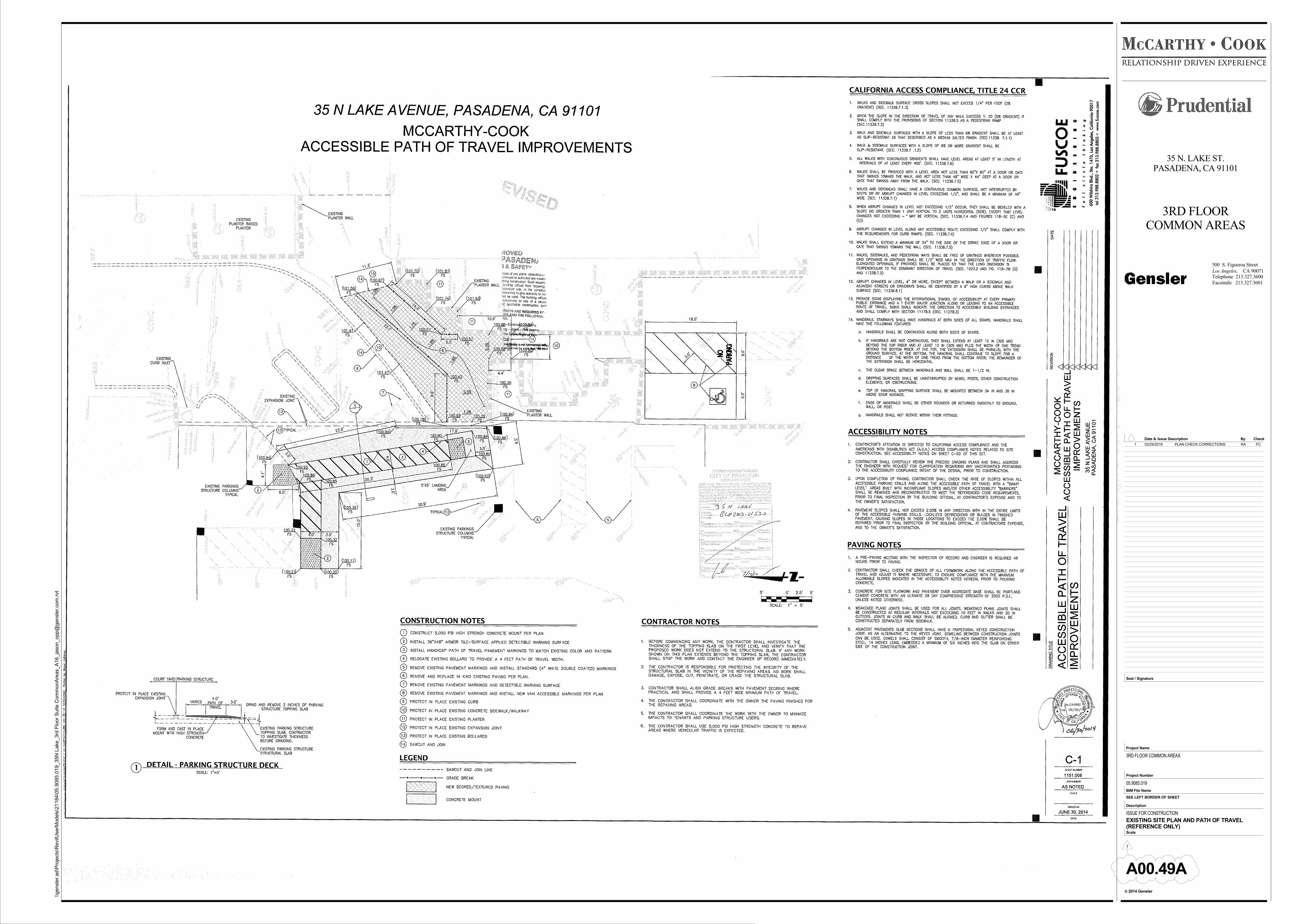
CA 90071Los Angeles,
2014 Gensler
Project Number
BIM File Name
Scale
Description
c
Project Name
Seal / Signature
Check
Facsimile 213.327.3601
Telephone 213.327.3600
Date & By
500 S. Figueroa Street
Issue Description
SEE LEFT BORDER OF SHEET
\\ge
nsl
er.
ad\P
roje
cts
\RevitU
serM
od
els
\21
184
\05
.90
85.0
19
_35
N L
ake
_3rd
Flo
or
Su
ite C
om
mo
nA
reas_A
16_ja
son_o
pp@
gen
sle
r.com
.rvt
35 N. LAKE ST.PASADENA, CA 91101
3RD FLOORCOMMON AREAS
3RD FLOOR COMMON AREAS
05.9085.019
ISSUE FOR CONSTRUCTION
A00.49A
EXISTING SITE PLAN AND PATH OF TRAVEL(REFERENCE ONLY)
1
1 03/29/2016 PLAN CHECK CORRECTIONS RA FC
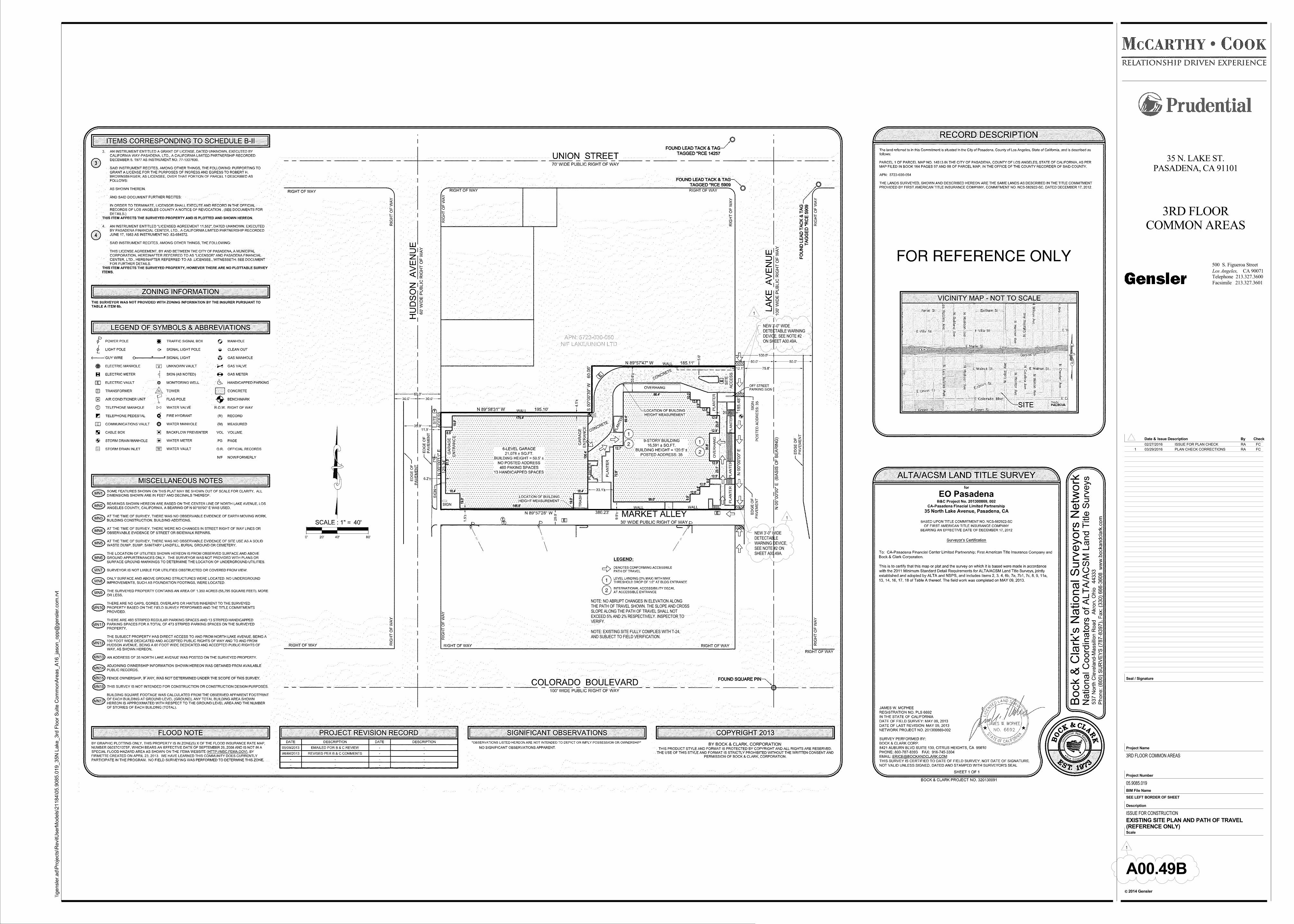
CA 90071Los Angeles,
2014 Gensler
Project Number
BIM File Name
Scale
Description
c
Project Name
Seal / Signature
Check
Facsimile 213.327.3601
Telephone 213.327.3600
Date & By
500 S. Figueroa Street
Issue Description
SEE LEFT BORDER OF SHEET
\\ge
nsl
er.
ad\P
roje
cts
\RevitU
serM
od
els
\21
184
\05
.90
85.0
19
_35
N L
ake
_3rd
Flo
or
Su
ite C
om
mo
nA
reas_A
16_ja
son_o
pp@
gen
sle
r.com
.rvt
35 N. LAKE ST.PASADENA, CA 91101
3RD FLOORCOMMON AREAS
3RD FLOOR COMMON AREAS
05.9085.019
ISSUE FOR CONSTRUCTION
A00.49B
EXISTING SITE PLAN AND PATH OF TRAVEL(REFERENCE ONLY)
1
NOTE: NO ABRUPT CHANGES IN ELEVATION ALONGTHE PATH OF TRAVEL SHOWN. THE SLOPE AND CROSSSLOPE ALONG THE PATH OF TRAVEL SHALL NOTEXCEED 5% AND 2% RESPECTIVELY. INSPECTOR TOVERIFY.
NOTE: EXISTING SITE FULLY COMPLIES WITH T-24,AND SUBJECT TO FIELD VERIFICATION.
NEW 3'-0" WIDEDETECTABLEWARNING DEVICE,SEE NOTE #2 ONSHEET A00.49A.
NEW 3'-0" WIDEDETECTABLE WARNINGDEVICE, SEE NOTE #2ON SHEET A00.49A.
1
1
02/27/2016 ISSUE FOR PLAN CHECK RA FC
1 03/29/2016 PLAN CHECK CORRECTIONS RA FC
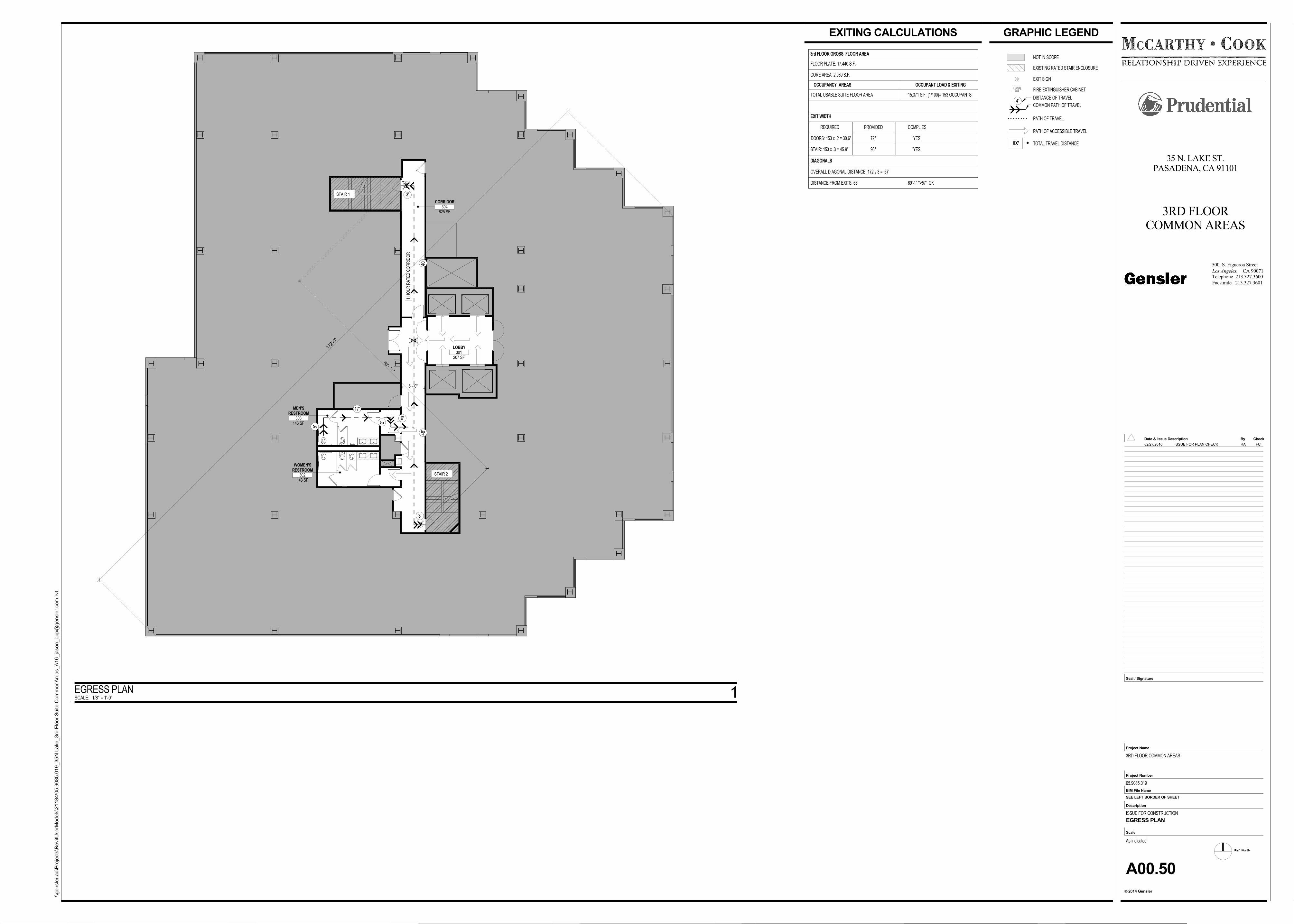
F.E.C.(N)
4'
48'
40'
3'
3'
5'
17'
2'
6'
EXISTING RATED STAIR ENCLOSURE
FIRE EXTINGUISHER CABINET
COMMON PATH OF TRAVEL
PATH OF ACCESSIBLE TRAVEL
NOT IN SCOPE
EXIT SIGN
PATH OF TRAVEL
DISTANCE OF TRAVEL
XX' TOTAL TRAVEL DISTANCE
OCCUPANCY AREAS OCCUPANT LOAD & EXITING
15,371 S.F. (1/100)= 153 OCCUPANTSTOTAL USABLE SUITE FLOOR AREA
REQUIRED
EXIT WIDTH
PROVIDED COMPLIES
DOORS: 153 x .2 = 30.6"
STAIR: 153 x .3 = 45.9"
72"
96"
YES
YES
OVERALL DIAGONAL DISTANCE: 172' / 3 = 57'
DISTANCE FROM EXITS: 68'
FLOOR PLATE: 17,440 S.F.
CORE AREA: 2,069 S.F.
3rd FLOOR GROSS FLOOR AREA
DIAGONALS
69'-11"'>57' OK
146 SF
MEN'SRESTROOM
303
1 H
OU
R R
ATE
D C
OR
RID
OR
172'-
0"
6' - 0"
207 SF
LOBBY301
625 SF
CORRIDOR304
STAIR 1
STAIR 2
143 SF
WOMEN'SRESTROOM
302
68' - 11"
Ref. North
CA 90071Los Angeles,
2014 Gensler
Project Number
BIM File Name
Scale
Description
c
Project Name
Seal / Signature
Check
Facsimile 213.327.3601
Telephone 213.327.3600
Date & By
500 S. Figueroa Street
Issue Description
SEE LEFT BORDER OF SHEET
\\ge
nsl
er.
ad\P
roje
cts
\RevitU
serM
od
els
\21
184
\05
.90
85.0
19
_35
N L
ake
_3rd
Flo
or
Su
ite C
om
mo
nA
reas_A
16_ja
son_o
pp@
gen
sle
r.com
.rvt
As indicated
35 N. LAKE ST.PASADENA, CA 91101
3RD FLOORCOMMON AREAS
3RD FLOOR COMMON AREAS
05.9085.019
ISSUE FOR CONSTRUCTION
A00.50
EGRESS PLAN
GRAPHIC LEGENDEXITING CALCULATIONS
SCALE: 1/8" = 1'-0"
EGRESS PLAN 1
02/27/2016 ISSUE FOR PLAN CHECK RA FC
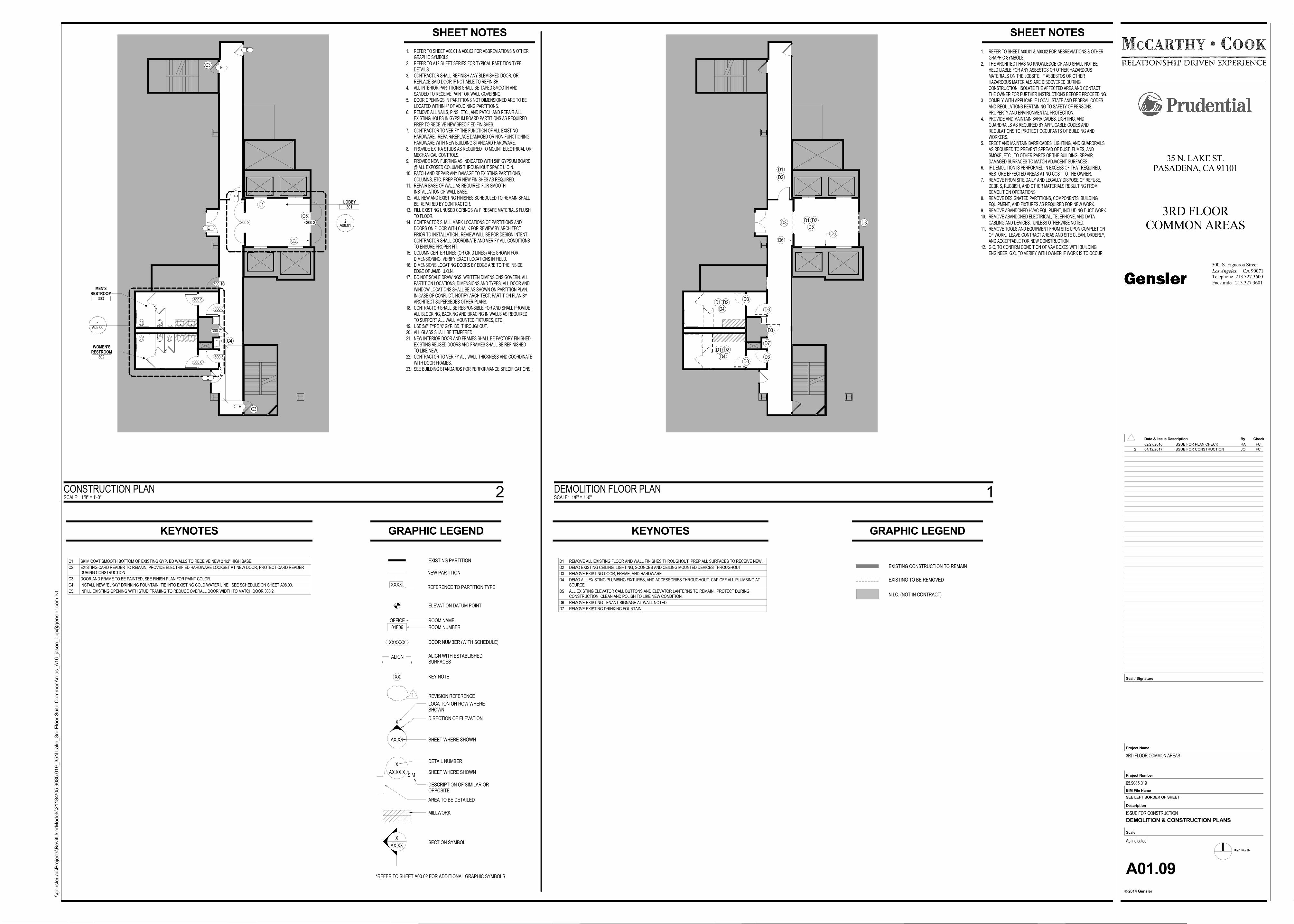
1. REFER TO SHEET A00.01 & A00.02 FOR ABBREVIATIONS & OTHERGRAPHIC SYMBOLS.
2. REFER TO A12 SHEET SERIES FOR TYPICAL PARTITION TYPEDETAILS.
3. CONTRACTOR SHALL REFINISH ANY BLEMISHED DOOR, ORREPLACE SAID DOOR IF NOT ABLE TO REFINISH.
4. ALL INTERIOR PARTITIONS SHALL BE TAPED SMOOTH ANDSANDED TO RECEIVE PAINT OR WALL COVERING.
5. DOOR OPENINGS IN PARTITIONS NOT DIMENSIONED ARE TO BELOCATED WITHIN 4" OF ADJOINING PARTITIONS.
6. REMOVE ALL NAILS, PINS, ETC., AND PATCH AND REPAIR ALLEXISTING HOLES IN GYPSUM BOARD PARTITIONS AS REQUIRED.PREP TO RECEIVE NEW SPECIFIED FINISHES.
7. CONTRACTOR TO VERIFY THE FUNCTION OF ALL EXISTINGHARDWARE. REPAIR/REPLACE DAMAGED OR NON-FUNCTIONINGHARDWARE WITH NEW BUILDING STANDARD HARDWARE.
8. PROVIDE EXTRA STUDS AS REQUIRED TO MOUNT ELECTRICAL ORMECHANICAL CONTROLS.
9. PROVIDE NEW FURRING AS INDICATED WITH 5/8" GYPSUM BOARD@ ALL EXPOSED COLUMNS THROUGHOUT SPACE U.O.N.
10. PATCH AND REPAIR ANY DAMAGE TO EXISTING PARTITIONS,COLUMNS, ETC. PREP FOR NEW FINISHES AS REQUIRED.
11. REPAIR BASE OF WALL AS REQUIRED FOR SMOOTHINSTALLATION OF WALL BASE.
12. ALL NEW AND EXISTING FINISHES SCHEDULED TO REMAIN SHALLBE REPAIRED BY CONTRACTOR.
13. FILL EXISTING UNUSED CORINGS W/ FIRESAFE MATERIALS FLUSHTO FLOOR.
14. CONTRACTOR SHALL MARK LOCATIONS OF PARTITIONS ANDDOORS ON FLOOR WITH CHALK FOR REVIEW BY ARCHITECTPRIOR TO INSTALLATION.. REVIEW WILL BE FOR DESIGN INTENT.CONTRACTOR SHALL COORDINATE AND VERIFY ALL CONDITIONSTO ENSURE PROPER FIT.
15. COLUMN CENTER LINES (OR GRID LINES) ARE SHOWN FORDIMENSIONING, VERIFY EXACT LOCATIONS IN FIELD.
16. DIMENSIONS LOCATING DOORS BY EDGE ARE TO THE INSIDEEDGE OF JAMB, U.O.N.
17. DO NOT SCALE DRAWINGS. WRITTEN DIMENSIONS GOVERN. ALLPARTITION LOCATIONS, DIMENSIONS AND TYPES, ALL DOOR ANDWINDOW LOCATIONS SHALL BE AS SHOWN ON PARTITION PLAN.IN CASE OF CONFLICT, NOTIFY ARCHITECT; PARTITION PLAN BYARCHITECT SUPERSEDES OTHER PLANS.
18. CONTRACTOR SHALL BE RESPONSIBLE FOR AND SHALL PROVIDEALL BLOCKING, BACKING AND BRACING IN WALLS AS REQUIREDTO SUPPORT ALL WALL MOUNTED FIXTURES, ETC.
19. USE 5/8" TYPE 'X' GYP. BD. THROUGHOUT.20. ALL GLASS SHALL BE TEMPERED.21. NEW INTERIOR DOOR AND FRAMES SHALL BE FACTORY FINISHED.
EXISTING REUSED DOORS AND FRAMES SHALL BE REFINISHEDTO LIKE NEW.
22. CONTRACTOR TO VERIFY ALL WALL THICKNESS AND COORDINATEWITH DOOR FRAMES.
23. SEE BUILDING STANDARDS FOR PERFORMANCE SPECIFICATIONS.
C1
________________1A08.00
________________2A08.01
MEN'SRESTROOM
303
E
300.3
300.10
300.6
300.7
LOBBY301
C2
E
300.8
300.9
300.5
14' -
4"
E
WOMEN'SRESTROOM
302
300.2
E
C3
C3
C4
E
E
C5D1 D2D3
D3
D3
D3
D3D3
D3
D4
D4
D1 D2
D1 D2
D5
D6
D7
D1
D2
D6
1. REFER TO SHEET A00.01 & A00.02 FOR ABBREVIATIONS & OTHERGRAPHIC SYMBOLS.
2. THE ARCHITECT HAS NO KNOWLEDGE OF AND SHALL NOT BEHELD LIABLE FOR ANY ASBESTOS OR OTHER HAZARDOUSMATERIALS ON THE JOBSITE. IF ASBESTOS OR OTHERHAZARDOUS MATERIALS ARE DISCOVERED DURINGCONSTRUCTION, ISOLATE THE AFFECTED AREA AND CONTACTTHE OWNER FOR FURTHER INSTRUCTIONS BEFORE PROCEEDING.
3. COMPLY WITH APPLICABLE LOCAL, STATE AND FEDERAL CODESAND REGULATIONS PERTAINING TO SAFETY OF PERSONS,PROPERTY AND ENVIRONMENTAL PROTECTION.
4. PROVIDE AND MAINTAIN BARRICADES, LIGHTING, ANDGUARDRAILS AS REQUIRED BY APPLICABLE CODES ANDREGULATIONS TO PROTECT OCCUPANTS OF BUILDING ANDWORKERS.
5. ERECT AND MAINTAIN BARRICADES, LIGHTING, AND GUARDRAILSAS REQUIRED TO PREVENT SPREAD OF DUST, FUMES, ANDSMOKE, ETC., TO OTHER PARTS OF THE BUILDING. REPAIRDAMAGED SURFACES TO MATCH ADJACENT SURFACES..
6. IF DEMOLITION IS PERFORMED IN EXCESS OF THAT REQUIRED,RESTORE EFFECTED AREAS AT NO COST TO THE OWNER.
7. REMOVE FROM SITE DAILY AND LEGALLY DISPOSE OF REFUSE,DEBRIS, RUBBISH, AND OTHER MATERIALS RESULTING FROMDEMOLITION OPERATIONS.
8. REMOVE DESIGNATED PARTITIONS, COMPONENTS, BUILDINGEQUIPMENT, AND FIXTURES AS REQUIRED FOR NEW WORK.
9. REMOVE ABANDONED HVAC EQUIPMENT, INCLUDING DUCT WORK.10. REMOVE ABANDONED ELECTRICAL, TELEPHONE, AND DATA
CABLING AND DEVICES, UNLESS OTHERWISE NOTED.11. REMOVE TOOLS AND EQUIPMENT FROM SITE UPON COMPLETION
OF WORK. LEAVE CONTRACT AREAS AND SITE CLEAN, ORDERLY,AND ACCEPTABLE FOR NEW CONSTRUCTION.
12. G.C. TO CONFIRM CONDITION OF VAV BOXES WITH BUILDINGENGINEER. G.C. TO VERIFY WITH OWNER IF WORK IS TO OCCUR.
SIM
X
REVISION REFERENCE
MILLWORK
DESCRIPTION OF SIMILAR OROPPOSITE
LOCATION ON ROW WHERESHOWN
AREA TO BE DETAILED
SHEET WHERE SHOWN
DETAIL NUMBER
SHEET WHERE SHOWN
DIRECTION OF ELEVATION
1
AX.XX
AX.XX.X
X
ALIGN
KEY NOTE
DOOR NUMBER (WITH SCHEDULE)
ALIGN WITH ESTABLISHEDSURFACES
XXXXXX
XX
ROOM NAME
ROOM NUMBER
ELEVATION DATUM POINT
04F06
OFFICE
SECTION SYMBOLAX.XX
X
*REFER TO SHEET A00.02 FOR ADDITIONAL GRAPHIC SYMBOLS
NEW PARTITION
REFERENCE TO PARTITION TYPEXXXX
EXISTING PARTITIONEXISTING CONSTRUCTION TO REMAIN
EXISTING TO BE REMOVED
N.I.C. (NOT IN CONTRACT)
Ref. North
CA 90071Los Angeles,
2014 Gensler
Project Number
BIM File Name
Scale
Description
c
Project Name
Seal / Signature
Check
Facsimile 213.327.3601
Telephone 213.327.3600
Date & By
500 S. Figueroa Street
Issue Description
SEE LEFT BORDER OF SHEET
\\ge
nsl
er.
ad\P
roje
cts
\RevitU
serM
od
els
\21
184
\05
.90
85.0
19
_35
N L
ake
_3rd
Flo
or
Su
ite C
om
mo
nA
reas_A
16_ja
son_o
pp@
gen
sle
r.com
.rvt
As indicated
35 N. LAKE ST.PASADENA, CA 91101
3RD FLOORCOMMON AREAS
3RD FLOOR COMMON AREAS
05.9085.019
ISSUE FOR CONSTRUCTION
A01.09
DEMOLITION & CONSTRUCTION PLANS
SCALE: 1/8" = 1'-0"
CONSTRUCTION PLAN 2
KEYNOTES
SHEET NOTES
SCALE: 1/8" = 1'-0"
DEMOLITION FLOOR PLAN 1
D1 REMOVE ALL EXISTING FLOOR AND WALL FINISHES THROUGHOUT. PREP ALL SURFACES TO RECEIVE NEW.
D2 DEMO EXISTING CEILING, LIGHTING, SCONCES AND CEILING MOUNTED DEVICES THROUGHOUT
D3 REMOVE EXISTING DOOR, FRAME, AND HARDWARE
D4 DEMO ALL EXISTING PLUMBING FIXTURES, AND ACCESSORIES THROUGHOUT. CAP OFF ALL PLUMBING ATSOURCE.
D5 ALL EXISTING ELEVATOR CALL BUTTONS AND ELEVATOR LANTERNS TO REMAIN. PROTECT DURINGCONSTRUCTION. CLEAN AND POLISH TO LIKE NEW CONDITION.
D6 REMOVE EXISTING TENANT SIGNAGE AT WALL NOTED.
D7 REMOVE EXISTING DRINKING FOUNTAIN.
C1 SKIM COAT SMOOTH BOTTOM OF EXISTING GYP. BD WALLS TO RECEIVE NEW 2 1/2" HIGH BASE.
C2 EXISTING CARD READER TO REMAIN, PROVIDE ELECTRIFIED HARDWARE LOCKSET AT NEW DOOR, PROTECT CARD READERDURING CONSTRUCTION
C3 DOOR AND FRAME TO BE PAINTED, SEE FINISH PLAN FOR PAINT COLOR.
C4 INSTALL NEW "ELKAY" DRINKING FOUNTAIN, TIE INTO EXISTING COLD WATER LINE. SEE SCHEDULE ON SHEET A08.00.
C5 INFILL EXISTING OPENING WITH STUD FRAMING TO REDUCE OVERALL DOOR WIDTH TO MATCH DOOR 300.2.
KEYNOTES
SHEET NOTES
GRAPHIC LEGEND GRAPHIC LEGEND
02/27/2016 ISSUE FOR PLAN CHECK RA FC
2 04/12/2017 ISSUE FOR CONSTRUCTION JO FC
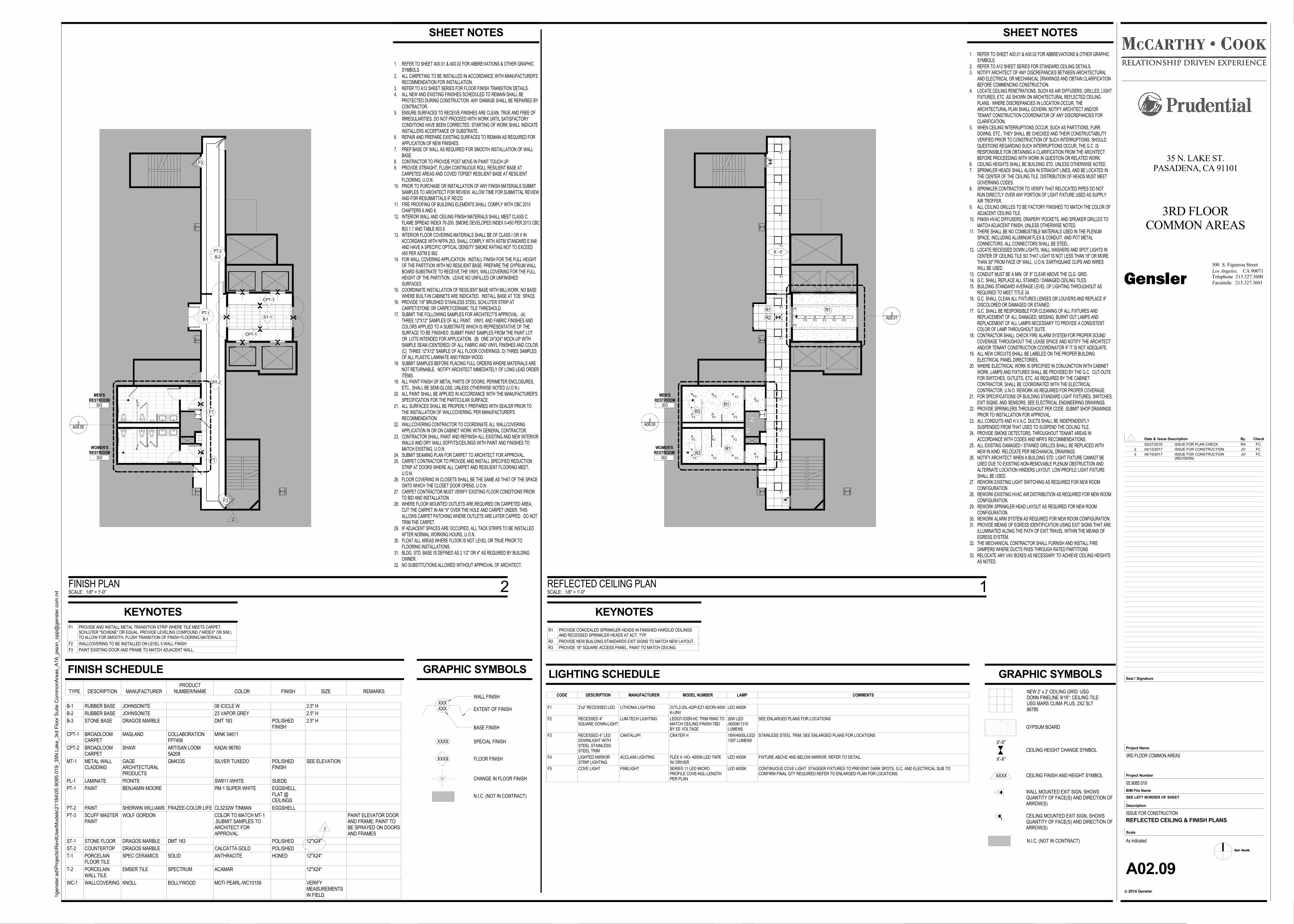
1. REFER TO SHEET A00.01 & A00.02 FOR ABBREVIATIONS & OTHER GRAPHICSYMBOLS.
2. REFER TO A12 SHEET SERIES FOR STANDARD CEILING DETAILS.3. NOTIFY ARCHITECT OF ANY DISCREPANCIES BETWEEN ARCHITECTURAL
AND ELECTRICAL OR MECHANICAL DRAWINGS AND OBTAIN CLARIFICATIONBEFORE COMMENCING CONSTRUCTION.
4. LOCATE CEILING PENETRATIONS, SUCH AS AIR DIFFUSERS, GRILLES, LIGHTFIXTURES, ETC. AS SHOWN ON ARCHITECTURAL REFLECTED CEILINGPLANS. WHERE DISCREPANCIES IN LOCATION OCCUR, THEARCHITECTURAL PLAN SHALL GOVERN. NOTIFY ARCHITECT AND/ORTENANT CONSTRUCTION COORDINATOR OF ANY DISCREPANCIES FORCLARIFICATION.
5. WHEN CEILING INTERRUPTIONS OCCUR, SUCH AS PARTITIONS, FURRDOWNS, ETC., THEY SHALL BE CHECKED AND THEIR CONSTRUCTABILITYVERIFIED PRIOR TO CONSTRUCTION OF SUCH INTERRUPTIONS. SHOULDQUESTIONS REGARDING SUCH INTERRUPTIONS OCCUR, THE G.C. ISRESPONSIBLE FOR OBTAINING A CLARIFICATION FROM THE ARCHITECTBEFORE PROCEEDING WITH WORK IN QUESTION OR RELATED WORK.
6. CEILING HEIGHTS SHALL BE BUILDING STD. UNLESS OTHERWISE NOTED.7. SPRINKLER HEADS SHALL ALIGN IN STRAIGHT LINES, AND BE LOCATED IN
THE CENTER OF THE CEILING TILE. DISTRIBUTION OF HEADS MUST MEETGOVERNING CODES.
8. SPRINKLER CONTRACTOR TO VERIFY THAT RELOCATED PIPES DO NOTRUN DIRECTLY OVER ANY PORTION OF LIGHT FIXTURE USED AS SUPPLYAIR TROFFER.
9. ALL CEILING GRILLES TO BE FACTORY FINISHED TO MATCH THE COLOR OFADJACENT CEILING TILE.
10. FINISH HVAC DIFFUSERS, DRAPERY POCKETS, AND SPEAKER GRILLES TOMATCH ADJACENT FINISH, UNLESS OTHERWISE NOTED.
11. THERE SHALL BE NO COMBUSTIBLE MATERIALS USED IN THE PLENUMSPACE, INCLUDING ALUMINUM FLEX & CONDUIT, AND POT METALCONNECTORS. ALL CONNECTORS SHALL BE STEEL.
12. LOCATE RECESSED DOWN LIGHTS, WALL WASHERS AND SPOT LIGHTS INCENTER OF CEILING TILE SO THAT LIGHT IS NOT LESS THAN 18" OR MORETHAN 30" FROM FACE OF WALL, U.O.N. EARTHQUAKE CLIPS AND WIRESWILL BE USED.
13. CONDUIT MUST BE A MIN. OF 8" CLEAR ABOVE THE CLG. GRID.14. G.C. SHALL REPLACE ALL STAINED / DAMAGED CEILING TILES.15. BUILDING STANDARD AVERAGE LEVEL OF LIGHTING THROUGHOUT AS
REQUIRED TO MEET TITLE 24.16. G.C. SHALL CLEAN ALL FIXTURES LENSES OR LOUVERS AND REPLACE IF
DISCOLORED OR DAMAGED OR STAINED.17. G.C. SHALL BE RESPONSIBLE FOR CLEANING OF ALL FIXTURES AND
REPLACEMENT OF ALL DAMAGED, MISSING, BURNT OUT LAMPS ANDREPLACEMENT OF ALL LAMPS NECESSARY TO PROVIDE A CONSISTENTCOLOR OF LAMP THROUGHOUT SUITE.
18. CONTRACTOR SHALL CHECK FIRE ALARM SYSTEM FOR PROPER SOUNDCOVERAGE THROUGHOUT THE LEASE SPACE AND NOTIFY THE ARCHITECTAND/OR TENANT CONSTRUCTION COORDINATOR IF IT IS NOT ADEQUATE.
19. ALL NEW CIRCUITS SHALL BE LABELED ON THE PROPER BUILDINGELECTRICAL PANEL DIRECTORIES.
20. WHERE ELECTRICAL WORK IS SPECIFIED IN CONJUNCTION WITH CABINETWORK, LAMPS AND FIXTURES SHALL BE PROVIDED BY THE G.C. CUT-OUTSFOR SWITCHES, OUTLETS, ETC. AS REQUIRED BY THE CABINETCONTRACTOR, SHALL BE COORDINATED WITH THE ELECTRICALCONTRACTOR, U.N.O. REWORK AS REQUIRED FOR PROPER COVERAGE.
21. FOR SPECIFICATIONS OF BUILDING STANDARD LIGHT FIXTURES, SWITCHES,EXIT SIGNS, AND SENSORS, SEE ELECTRICAL ENGINEERING DRAWINGS.
22. PROVIDE SPRINKLERS THROUGHOUT PER CODE. SUBMIT SHOP DRAWINGSPRIOR TO INSTALLATION FOR APPROVAL.
23. ALL CONDUITS AND H.V.A.C. DUCTS SHALL BE INDEPENDENTLYSUSPENDED FROM THAT USED TO SUSPEND THE CEILING TILE.
24. PROVIDE SMOKE DETECTORS, THROUGHOUT TENANT AREAS INACCORDANCE WITH CODES AND MFR'S RECOMMENDATIONS.
25. ALL EXISTING DAMAGED / STAINED GRILLES SHALL BE REPLACED WITHNEW IN KIND. RELOCATE PER MECHANICAL DRAWINGS.
26. NOTIFY ARCHITECT WHEN A BUILDING STD. LIGHT FIXTURE CANNOT BEUSED DUE TO EXISTING NON-REMOVABLE PLENUM OBSTRUCTION ANDALTERNATE LOCATION HINDERS LAYOUT, LOW PROFILE LIGHT FIXTURESHALL BE USED.
27. REWORK EXISTING LIGHT SWITCHING AS REQUIRED FOR NEW ROOMCONFIGURATION.
28. REWORK EXISTING HVAC AIR DISTRIBUTION AS REQUIRED FOR NEW ROOMCONFIGURATION.
29. REWORK SPRINKLER HEAD LAYOUT AS REQUIRED FOR NEW ROOMCONFIGURATION.
30. REWORK ALARM SYSTEM AS REQUIRED FOR NEW ROOM CONFIGURATION.31. PROVIDE MEANS OF EGRESS IDENTIFICATION USING EXIT SIGNS THAT ARE
ILLUMINATED ALONG THE PATH OF EXIT TRAVEL WITHIN THE MEANS OFEGRESS SYSTEM.
32. THE MECHANICAL CONTRACTOR SHALL FURNISH AND INSTALL FIREDAMPERS WHERE DUCTS PASS THROUGH RATED PARTITIONS
33. RELOCATE ANY VAV BOXES AS NECESSARY TO ACHIEVE CEILING HEIGHTSAS NOTED.
X'-X"
X'-X"
WALL MOUNTED EXIT SIGN, SHOWSQUANTITY OF FACE(S) AND DIRECTION OFARROW(S)
CEILING HEIGHT CHANGE SYMBOL
CEILING FINISH AND HEIGHT SYMBOL
CEILING MOUNTED EXIT SIGN, SHOWSQUANTITY OF FACE(S) AND DIRECTION OFARROW(S)
GYPSUM BOARD
XXXX
N.I.C. (NOT IN CONTRACT)
NEW 2' x 2' CEILING GRID: USGDONN FINELINE 9/16"; CEILING TILE:USG MARS CLIMA PLUS, 2X2 SLT86785
R1
MEN'SRESTROOM
303
________________3A08.01
F1
F1
F1
F1
F1
F1
F1
F1
F1
F1
F1
F3 F3 F3 F3 F3
F2 F2 F2
F2 F2 F2
F2 F2 F2
F2 F2 F2
F2
F2
F5
F5
F4
F4
R2
________________2A08.00
F1
R1
R1
R1WOMEN'SRESTROOM
302
R3
R3
8' - 5"
CHANGE IN FLOOR FINISH
EXTENT OF FINISH
BASE FINISH
WALL FINISH
XXXX
XXXX SPECIAL FINISH
FLOOR FINISH
XXX
N.I.C. (NOT IN CONTRACT)
XXX
B-1
PT-1
MEN'SRESTROOM
303
F1
CPT-2
________________3A08.00
B-2
F1
CPT-1
CPT-1
ST-1
PT-2
WOMEN'SRESTROOM
302
F3
F3
1. REFER TO SHEET A00.01 & A00.02 FOR ABBREVIATIONS & OTHER GRAPHICSYMBOLS.
2. ALL CARPETING TO BE INSTALLED IN ACCORDANCE WITH MANUFACTURER'SRECOMMENDATION FOR INSTALLATION.
3. REFER TO A12 SHEET SERIES FOR FLOOR FINISH TRANSITION DETAILS.4. ALL NEW AND EXISTING FINISHES SCHEDULED TO REMAIN SHALL BE
PROTECTED DURING CONSTRUCTION. ANY DAMAGE SHALL BE REPAIRED BYCONTRACTOR.
5. ENSURE SURFACES TO RECEIVE FINISHES ARE CLEAN, TRUE AND FREE OFIRREGULARITIES. DO NOT PROCEED WITH WORK UNTIL SATISFACTORYCONDITIONS HAVE BEEN CORRECTED. STARTING OF WORK SHALL INDICATEINSTALLERS ACCEPTANCE OF SUBSTRATE.
6. REPAIR AND PREPARE EXISTING SURFACES TO REMAIN AS REQUIRED FORAPPLICATION OF NEW FINISHES.
7. PREP BASE OF WALL AS REQUIRED FOR SMOOTH INSTALLATION OF WALLBASE.
8. CONTRACTOR TO PROVIDE POST MOVE-IN PAINT TOUCH UP.9. PROVIDE STRAIGHT, FLUSH CONTINUOUS ROLL RESILIENT BASE AT
CARPETED AREAS AND COVED TOPSET RESILIENT BASE AT RESILIENTFLOORING, U.O.N.
10. PRIOR TO PURCHASE OR INSTALLATION OF ANY FINISH MATERIALS SUBMITSAMPLES TO ARCHITECT FOR REVIEW. ALLOW TIME FOR SUBMITTAL REVIEWAND FOR RESUBMITTALS IF REQ'D.
11. FIRE PROOFING OF BUILDING ELEMENTS SHALL COMPLY WITH CBC 2010CHAPTERS 6 AND 8.
12. INTERIOR WALL AND CEILING FINISH MATERIALS SHALL MEET CLASS C:FLAME SPREAD INDEX 76-200: SMOKE DEVELOPED INDEX 0-450 PER 2013 CBC803.1.1 AND TABLE 803.9.
13. INTERIOR FLOOR COVERING MATERIALS SHALL BE OF CLASS I OR II INACCORDANCE WITH NFPA 253, SHALL COMPLY WITH ASTM STANDARD E 648AND HAVE A SPECIFIC OPTICAL DENSITY SMOKE RATING NOT TO EXCEED450 PER ASTM E 662
14. FOR WALL COVERING APPLICATION: INSTALL FINISH FOR THE FULL HEIGHTOF THE PARTITION WITH NO RESILIENT BASE. PREPARE THE GYPSUM WALLBOARD SUBSTRATE TO RECEIVE THE VINYL WALLCOVERING FOR THE FULLHEIGHT OF THE PARTITION. LEAVE NO UNFILLED OR UNFINISHEDSURFACES.
15. COORDINATE INSTALLATION OF RESILIENT BASE WITH MILLWORK. NO BASEWHERE BUILT-IN CABINETS ARE INDICATED. INSTALL BASE AT TOE SPACE.
16. PROVIDE 1/8" BRUSHED STAINLESS STEEL SCHLUTER STRIP ATCARPET/STONE OR CARPET/CERAMIC TILE THRESHOLD.
17. SUBMIT THE FOLLOWING SAMPLES FOR ARCHITECT'S APPROVAL: (A)THREE 12"X12" SAMPLES OF ALL PAINT. VINYL AND FABRIC FINISHES ANDCOLORS APPLIED TO A SUBSTRATE WHICH IS REPRESENTATIVE OF THESURFACE TO BE FINISHED. SUBMIT PAINT SAMPLES FROM THE PAINT LOTOR LOTS INTENDED FOR APPLICATION. (B) ONE 24"X24" MOCK-UP WITHSAMPLE SEAM (CENTERED) OF ALL FABRIC AND VINYL FINISHES AND COLOR.(C) THREE 12"X12" SAMPLE OF ALL FLOOR COVERINGS. D) THREE SAMPLESOF ALL PLASTIC LAMINATE AND FINISH WOOD.
18. SUBMIT SAMPLES BEFORE PLACING FULL ORDERS WHERE MATERIALS ARENOT RETURNABLE. NOTIFY ARCHITECT IMMEDIATELY OF LONG LEAD ORDERITEMS.
19. ALL PAINT FINISH OF METAL PARTS OF DOORS, PERIMETER ENCLOSURES,ETC., SHALL BE SEMI-GLOSS, UNLESS OTHERWISE NOTED (U.O.N.)
20. ALL PAINT SHALL BE APPLIED IN ACCORDANCE WITH THE MANUFACTURER'SSPECIFICATION FOR THE PARTICULAR SURFACE.
21. ALL SURFACES SHALL BE PROPERLY PREPARED WITH SEALER PRIOR TOTHE INSTALLATION OF WALLCOVERING, PER MANUFACTURER'SRECOMMENDATION.
22. WALLCOVERING CONTRACTOR TO COORDINATE ALL WALLCOVERINGAPPLICATION IN OR ON CABINET WORK WITH GENERAL CONTRACTOR.
23. CONTRACTOR SHALL PAINT AND REFINISH ALL EXISTING AND NEW INTERIORWALLS AND DRY WALL SOFFITS/CEILINGS WITH PAINT AND FINISHES TOMATCH EXISTING, U.O.N.
24. SUBMIT SEAMING PLAN FOR CARPET TO ARCHITECT FOR APPROVAL.25. CARPET CONTRACTOR TO PROVIDE AND INSTALL SPECIFIED REDUCTION
STRIP AT DOORS WHERE ALL CARPET AND RESILIENT FLOORING MEET,U.O.N.
26. FLOOR COVERING IN CLOSETS SHALL BE THE SAME AS THAT OF THE SPACEONTO WHICH THE CLOSET DOOR OPENS, U.O.N.
27. CARPET CONTRACTOR MUST VERIFY EXISTING FLOOR CONDITIONS PRIORTO BID AND INSTALLATION.
28. WHERE FLOOR MOUNTED OUTLETS ARE REQUIRED ON CARPETED AREA,CUT THE CARPET IN AN "X" OVER THE HOLE AND CARPET UNDER, THISALLOWS CARPET PATCHING WHERE OUTLETS ARE LATER CAPPED. DO NOTTRIM THE CARPET.
29. IF ADJACENT SPACES ARE OCCUPIED, ALL TACK STRIPS TO BE INSTALLEDAFTER NORMAL WORKING HOURS, U.O.N.
30. FLOAT ALL AREAS WHERE FLOOR IS NOT LEVEL OR TRUE PRIOR TOFLOORING INSTALLATIONS.
31. BLDG. STD. BASE IS DEFINED AS 2 1/2" OR 4" AS REQUIRED BY BUILDINGOWNER.
32. NO SUBSTITUTIONS ALLOWED WITHOUT APPROVAL OF ARCHITECT.
Ref. North
CA 90071Los Angeles,
2014 Gensler
Project Number
BIM File Name
Scale
Description
c
Project Name
Seal / Signature
Check
Facsimile 213.327.3601
Telephone 213.327.3600
Date & By
500 S. Figueroa Street
Issue Description
SEE LEFT BORDER OF SHEET
\\ge
nsl
er.
ad\P
roje
cts
\RevitU
serM
od
els
\21
184
\05
.90
85.0
19
_35
N L
ake
_3rd
Flo
or
Su
ite C
om
mo
nA
reas_A
16_ja
son_o
pp@
gen
sle
r.com
.rvt
As indicated
35 N. LAKE ST.PASADENA, CA 91101
3RD FLOORCOMMON AREAS
3RD FLOOR COMMON AREAS
05.9085.019
ISSUE FOR CONSTRUCTION
A02.09
REFLECTED CEILING & FINISH PLANS
LIGHTING SCHEDULE
R1 PROVIDE CONCEALED SPRINKLER HEADS IN FINISHED HARDLID CEILINGSAND RECESSED SPRINKLER HEADS AT ACT, TYP.
R2 PROVIDE NEW BUILDING STANDARDS EXIT SIGNS TO MATCH NEW LAYOUT.
R3 PROVIDE 18" SQUARE ACCESS PANEL, PAINT TO MATCH CEILING.
CODE DESCRIPTION MANUFACTURER MODEL NUMBER LAMP COMMENTS
F1 2'x2' RECESSED LED LITHONIA LIGHTING 2VTL2-20L-ADP-EZ1-82CRI-4000K-UNV
LED 4000K
F2 RECESSED 4"SQUARE DOWN-LIGHT
LUM-TECH LIGHTING LEDQT-535R-HC TRIM RING TOMATCH CEILING FINISH-TBDBY EE VOLTAGE
26W LED/4000K/1310LUMENS
SEE ENLARGED PLANS FOR LOCATIONS
F3 RECESSED 4" LEDDOWNLIGHT WITHSTEEL STAINLESSSTEEL TRIM
CANTALUPI CRATER H 18W/4000L/LED/1397 LUMENS
STAINLESS STEEL TRIM; SEE ENLARGED PLANS FOR LOCATIONS
F4 LIGHTED MIRRORSTRIP LIGHTING
ACCLAIM LIGHTING FLEX II- HO- 4000K-LED TAPEW/ DRIVER
LED 4000K FIXTURE ABOVE AND BELOW MIRROR. REFER TO DETAIL.
F5 COVE LIGHT FINELIGHT SERIES 11 LED MICROPROFILE COVE-NGL-LENGTHPER PLAN
LED 4000K CONTINUOUS COVE LIGHT. STAGGER FIXTURES TO PREVENT DARK SPOTS. G.C. AND ELECTRICAL SUB TOCONFIRM FINAL QTY REQUIRED.REFER TO ENLARGED PLAN FOR LOCATIONS.
KEYNOTES
SHEET NOTES
GRAPHIC SYMBOLS
SCALE: 1/8" = 1'-0"
REFLECTED CEILING PLAN 1
GRAPHIC SYMBOLS
SCALE: 1/8" = 1'-0"
FINISH PLAN 2
SHEET NOTES
F1 PROVIDE AND INSTALL METAL TRANSITION STRIP WHERE TILE MEETS CARPET.SCHLUTER "SCHIENE" OR EQUAL. PROVIDE LEVELING COMPOUND ("ARDEX" OR SIM.)TO ALLOW FOR SMOOTH, FLUSH TRANSITION OF FINISH FLOORING MATERIALS.
F2 WALLCOVERING TO BE INSTALLED ON LEVEL 5 WALL FINISH
F3 PAINT EXISTING DOOR AND FRAME TO MATCH ADJACENT WALL.
KEYNOTES
TYPE DESCRIPTION MANUFACTURERPRODUCT
NUMBER/NAME COLOR FINISH SIZE REMARKS
B-1 RUBBER BASE JOHNSONITE 08 ICICLE W 2.5" H
B-2 RUBBER BASE JOHNSONITE 23 VAPOR GREY 2.5" H
B-3 STONE BASE DRAGOS MARBLE DMT 183 POLISHEDFINISH
2.5" H
CPT-1 BROADLOOMCARPET
MASLAND COLLABORATIONFP7456
MINK 54611
CPT-2 BROADLOOMCARPET
SHAW ARTISAN LOOM5A208
KADAI 96760
MT-1 METAL WALLCLADDING
GAGEARCHITECTURALPRODUCTS
GM433S SILVER TUXEDO POLISHEDFINISH
SEE ELEVATION
PL-1 LAMINATE PIONITE SW811-WHITE SUEDE
PT-1 PAINT BENJAMIN MOORE PM-1 SUPER WHITE EGGSHELL,FLAT @CEILINGS
PT-2 PAINT SHERWIN WILLIAMS FRAZEE-COLOR LIFE CL3232W TINMAN EGGSHELL
PT-3 SCUFF MASTERPAINT
WOLF GORDON COLOR TO MATCH MT-1.SUBMIT SAMPLES TOARCHITECT FORAPPROVAL.
PAINT ELEVATOR DOORAND FRAME; PAINT TOBE SPRAYED ON DOORSAND FRAMES
ST-1 STONE FLOOR DRAGOS MARBLE DMT 183 POLISHED 12"X24"
ST-2 COUNTERTOP DRAGOS MARBLE CALCATTA GOLD POLISHED
T-1 PORCELAINFLOOR TILE
SPEC CERAMICS SOLID ANTHRACITE HONED 12"X24"
T-2 PORCELAINWALL TILE
EMSER TILE SPECTRUM ACAMAR 12"X24"
WC-1 WALLCOVERING KNOLL BOLLYWOOD MOTI PEARL-WC10159 VERIFYMEASUREMENTSIN FIELD.
FINISH SCHEDULE
02/27/2016 ISSUE FOR PLAN CHECK RA FC
2 04/12/2017 ISSUE FOR CONSTRUCTION JO FC
3 06/19/2017 ISSUE FOR CONSTRUCTION(REVISION)
JO FC
2
3
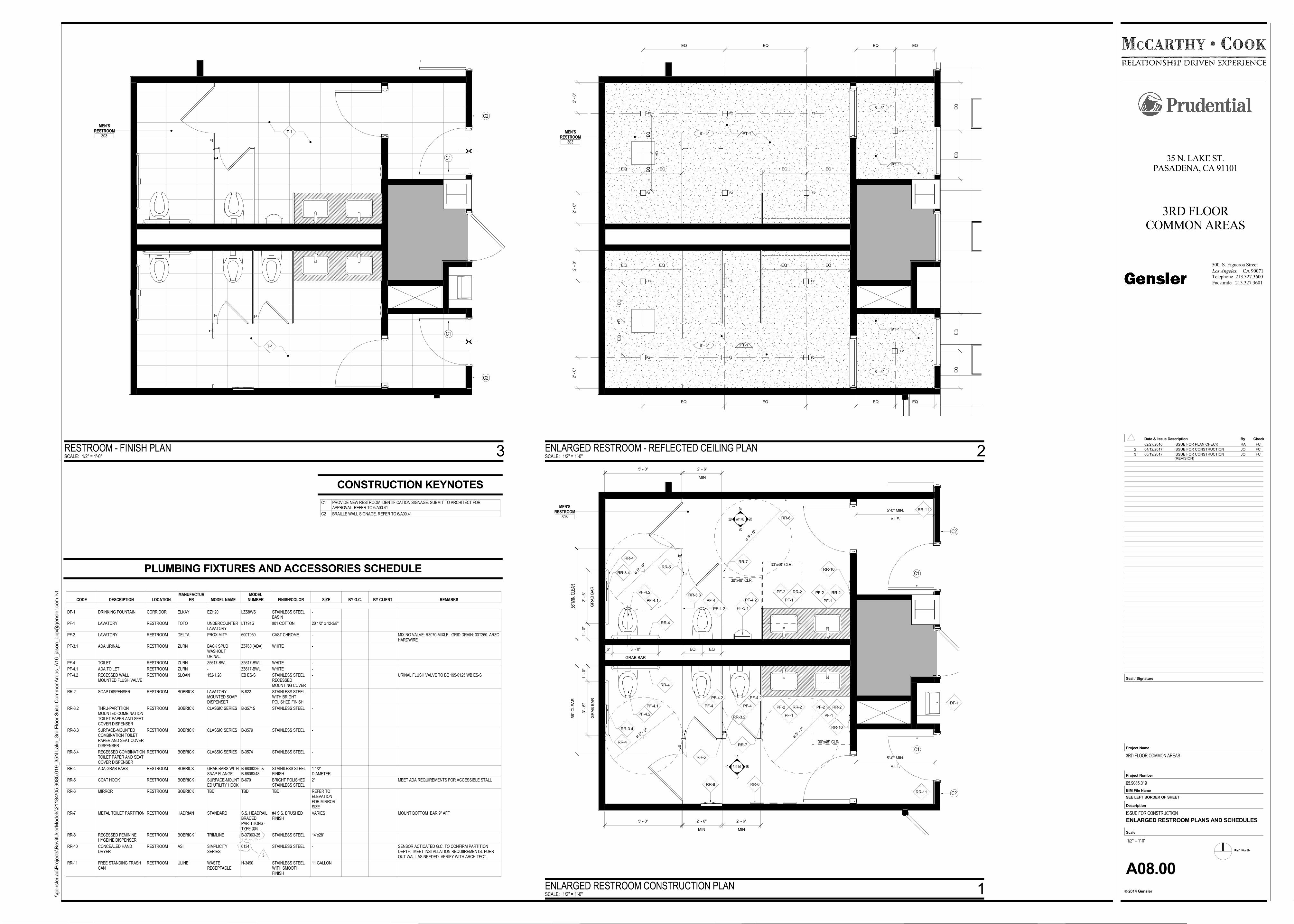
A11.00
2C
A11.00
1A
2D
1D
5' - 0"
MEN'SRESTROOM
303
56" M
IN. C
LEAR
GR
AB
BA
R
3' -
6"
1' -
0"
6"
GRAB BAR
3' - 0"
ø 5' -
0"
RR-4
RR-5
PF-4.2
PF-4.1
RR-3.4
MIN
2' - 6"
EQ EQ
RR-7
PF-3.1
30"x48" CLR.
30"x48" CLR.
PF-2
PF-1
RR-2 PF-2
PF-1
RR-2
2A
2B
RR-10
V.I.F.
5'-0" MIN. RR-11
RR-6
1' -
0"
GR
AB
BA
R
3' -
6"
56"
CLE
AR
ø 5' -
0"
RR-4
PF-4.2
PF-4.1
5' - 0"
MIN
2' - 6"
MIN
2' - 6"
RR-3.2
RR-5
RR-3.4
RR-6
30"x48" CLR.
RR-11
PF-2
PF-1
RR-2PF-2
PF-1
RR-2
V.I.F.
5'-0" MIN.
RR-10
PF-4
PF-4 PF-4
RR-7
RR-8
ø 5' -
0"
ø 5' -
0"
1B
1C
C1
C1
C2
C2
RR-4
RR-4
RR-3.3
PF-4.2
PF-4.2 PF-4.2
PF-4.2
DF-1
F2 F2 F2
F2 F2 F2
F2
F2
F2
F2
F2
F2
F2
F2
2' -
0"
2' -
0"
EQ EQ
EQ EQEQ EQ
EQ
EQ
EQ EQ
8' - 5"
8' - 5"
EQ EQ
2' -
0"
2' -
0"
EQ EQ
EQ EQ
EQ
EQ
EQ EQ
8' - 5"
8' - 5"
MEN'SRESTROOM
303
EQ
EQ
CL
EQ
EQ
CL
T-1
MEN'SRESTROOM
303
T-1
C1
C1
C2
C2
Ref. North
CA 90071Los Angeles,
2014 Gensler
Project Number
BIM File Name
Scale
Description
c
Project Name
Seal / Signature
Check
Facsimile 213.327.3601
Telephone 213.327.3600
Date & By
500 S. Figueroa Street
Issue Description
SEE LEFT BORDER OF SHEET
\\ge
nsl
er.
ad\P
roje
cts
\RevitU
serM
od
els
\21
184
\05
.90
85.0
19
_35
N L
ake
_3rd
Flo
or
Su
ite C
om
mo
nA
reas_A
16_ja
son_o
pp@
gen
sle
r.com
.rvt
1/2" = 1'-0"
35 N. LAKE ST.PASADENA, CA 91101
3RD FLOORCOMMON AREAS
3RD FLOOR COMMON AREAS
05.9085.019
ISSUE FOR CONSTRUCTION
A08.00
ENLARGED RESTROOM PLANS AND SCHEDULES
SCALE: 1/2" = 1'-0"
ENLARGED RESTROOM CONSTRUCTION PLAN 1
SCALE: 1/2" = 1'-0"
ENLARGED RESTROOM - REFLECTED CEILING PLAN 2SCALE: 1/2" = 1'-0"
RESTROOM - FINISH PLAN 3
CODE DESCRIPTION LOCATIONMANUFACTUR
ER MODEL NAMEMODEL
NUMBER FINISH/COLOR SIZE BY G.C. BY CLIENT REMARKS
DF-1 DRINKING FOUNTAIN CORRIDOR ELKAY EZH20 LZS8WS STAINLESS STEELBASIN
-
PF-1 LAVATORY RESTROOM TOTO UNDERCOUNTERLAVATORY
LT191G #01 COTTON 20 1/2" x 12-3/8"
PF-2 LAVATORY RESTROOM DELTA PROXIMITY 600T050 CAST CHROME - MIXING VALVE: R3070-MIXLF. GRID DRAIN: 33T260. ARZOHARDWIRE
PF-3.1 ADA URINAL RESTROOM ZURN BACK SPUDWASHOUTURINAL
Z5760 (ADA) WHITE -
PF-4 TOILET RESTROOM ZURN Z5617-BWL Z5617-BWL WHITE -
PF-4.1 ADA TOILET RESTROOM ZURN - Z5617-BWL WHITE -
PF-4.2 RECESSED WALLMOUNTED FLUSH VALVE
RESTROOM SLOAN 152-1.28 EB ES-S STAINLESS STEELRECESSEDMOUNTING COVER
- URINAL FLUSH VALVE TO BE 195-0125 WB ES-S
RR-2 SOAP DISPENSER RESTROOM BOBRICK LAVATORY -MOUNTED SOAPDISPENSER
B-822 STAINLESS STEELWITH BRIGHTPOLISHED FINISH
-
RR-3.2 THRU-PARTITIONMOUNTED COMBINATIONTOILET PAPER AND SEATCOVER DISPENSER
RESTROOM BOBRICK CLASSIC SERIES B-35715 STAINLESS STEEL -
RR-3.3 SURFACE-MOUNTEDCOMBINATION TOILETPAPER AND SEAT COVERDISPENSER
RESTROOM BOBRICK CLASSIC SERIES B-3579 STAINLESS STEEL -
RR-3.4 RECESSED COMBINATIONTOILET PAPER AND SEATCOVER DISPENSER
RESTROOM BOBRICK CLASSIC SERIES B-3574 STAINLESS STEEL -
RR-4 ADA GRAB BARS RESTROOM BOBRICK GRAB BARS WITHSNAP FLANGE
B-6806X36 &B-6806X48
STAINILESS STEELFINISH
1 1/2"DIAMETER
RR-5 COAT HOOK RESTROOM BOBRICK SURFACE-MOUNTED UTILITY HOOK
B-670 BRIGHT POLISHEDSTAINLESS STEEL
2" MEET ADA REQUIREMENTS FOR ACCESSIBLE STALL
RR-6 MIRROR RESTROOM BOBRICK TBD TBD TBD REFER TOELEVATIONFOR MIRRORSIZE
RR-7 METAL TOILET PARTITION RESTROOM HADRIAN STANDARD S.S. HEADRAILBRACEDPARTITIONS -TYPE 304
#4 S.S. BRUSHEDFINISH
VARIES MOUNT BOTTOM BAR 9" AFF
RR-8 RECESSED FEMININEHYGEINE DISPENSER
RESTROOM BOBRICK TRIMLINE B-37063-25 STAINLESS STEEL 14"x28"
RR-10 CONCEALED HANDDRYER
RESTROOM ASI SIMPLICITYSERIES
0134 STAINLESS STEEL - SENSOR ACTICATED G.C. TO CONFIRM PARTITIONDEPTH. MEET INSTALLATION REQUIIREMENTS. FURROUT WALL AS NEEDED. VERIFY WITH ARCHITECT.
RR-11 FREE STANDING TRASHCAN
RESTROOM ULINE WASTERECEPTACLE
H-3490 STAINLESS STEELWITH SMOOTHFINISH
11 GALLON
PLUMBING FIXTURES AND ACCESSORIES SCHEDULE
PT-1
PT-1
PT-1
PT-1
CONSTRUCTION KEYNOTES
C1 PROVIDE NEW RESTROOM IDENTIFICATION SIGNAGE. SUBMIT TO ARCHITECT FORAPPROVAL. REFER TO 6/A00.41
C2 BRAILLE WALL SIGNAGE. REFER TO 6/A00.41
02/27/2016 ISSUE FOR PLAN CHECK RA FC
2 04/12/2017 ISSUE FOR CONSTRUCTION JO FC
3 06/19/2017 ISSUE FOR CONSTRUCTION(REVISION)
JO FC
3
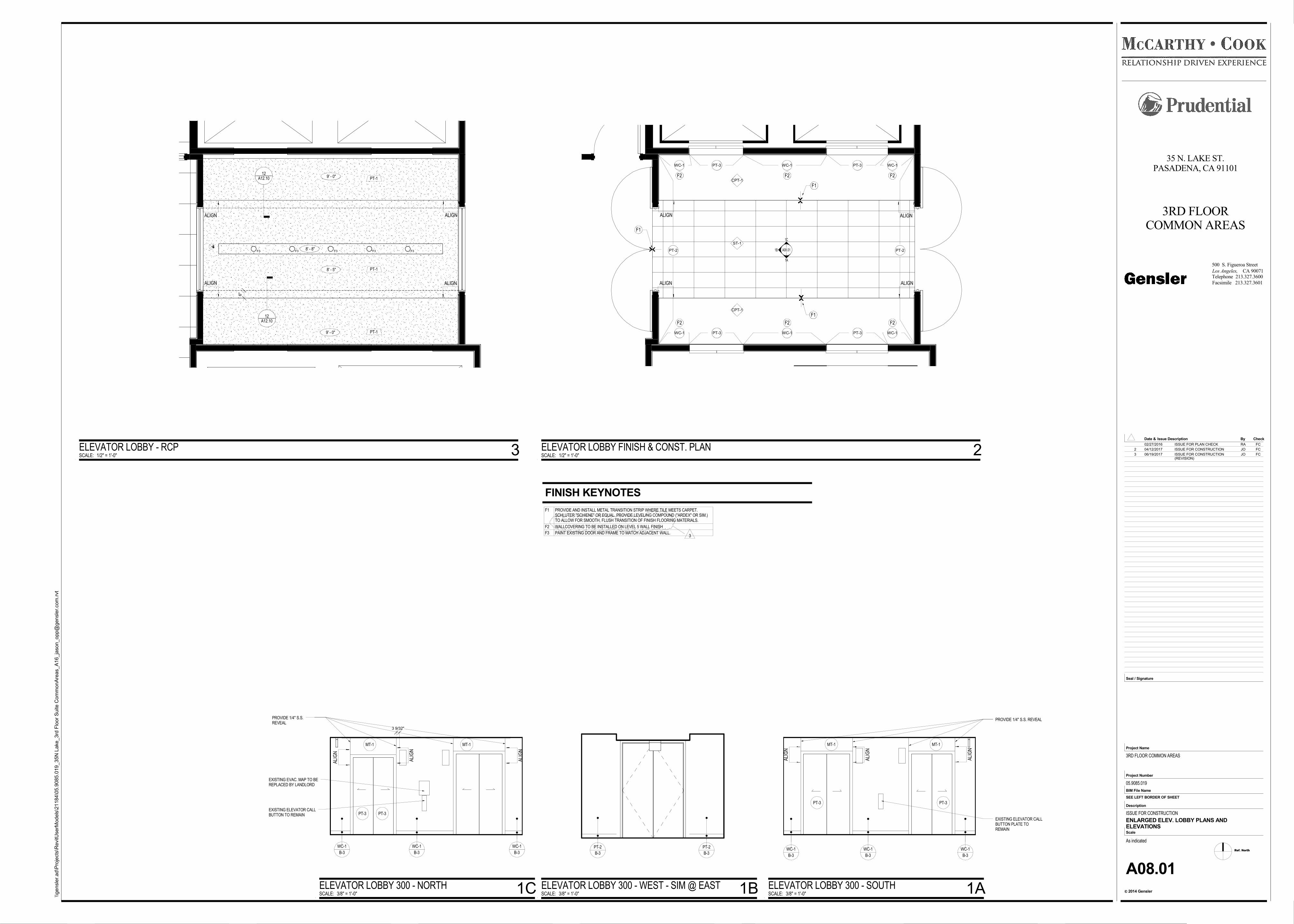
ALIGNALIGN
6"
ALIGN ALIGN
8' - 8"
8' - 5"
9' - 0"
9' - 0"
F3 F3 F3 F3 F3
12A12.10
________________
12A12.10
________________
PT-1
PT-1
PT-1
A08.01
1A
1C
1B
ST-1
PT-2
WC-1 PT-3 WC-1 PT-3 WC-1
PT-2
WC-1 PT-3 WC-1 PT-3 WC-1
CPT-1
ALIGNALIGN
ALIGN ALIGN
F1
F1
F2 F2 F2
F2F2F2
F1
CPT-1
ALI
GN
ALI
GN
ALI
GN
PROVIDE 1/4" S.S. REVEAL
EXISTING ELEVATOR CALLBUTTON PLATE TOREMAIN
WC-1
B-3
PT-3 PT-3
WC-1
B-3
WC-1
B-3
MT-1 MT-1
PT-2
B-3
PT-2
B-3
PROVIDE 1/4" S.S.REVEAL
EXISTING EVAC. MAP TO BEREPLACED BY LANDLORD
EXISTING ELEVATOR CALLBUTTON TO REMAIN
MT-1MT-1
3 9/32"
Ref. North
CA 90071Los Angeles,
2014 Gensler
Project Number
BIM File Name
Scale
Description
c
Project Name
Seal / Signature
Check
Facsimile 213.327.3601
Telephone 213.327.3600
Date & By
500 S. Figueroa Street
Issue Description
SEE LEFT BORDER OF SHEET
\\ge
nsl
er.
ad\P
roje
cts
\RevitU
serM
od
els
\21
184
\05
.90
85.0
19
_35
N L
ake
_3rd
Flo
or
Su
ite C
om
mo
nA
reas_A
16_ja
son_o
pp@
gen
sle
r.com
.rvt
As indicated
35 N. LAKE ST.PASADENA, CA 91101
3RD FLOORCOMMON AREAS
3RD FLOOR COMMON AREAS
05.9085.019
ISSUE FOR CONSTRUCTION
A08.01
ENLARGED ELEV. LOBBY PLANS ANDELEVATIONS
SCALE: 1/2" = 1'-0"
ELEVATOR LOBBY - RCP 3 SCALE: 1/2" = 1'-0"
ELEVATOR LOBBY FINISH & CONST. PLAN 2
SCALE: 3/8" = 1'-0"
ELEVATOR LOBBY 300 - SOUTH 1ASCALE: 3/8" = 1'-0"
ELEVATOR LOBBY 300 - WEST - SIM @ EAST 1BSCALE: 3/8" = 1'-0"
ELEVATOR LOBBY 300 - NORTH 1C
ALI
GN
ALI
GN
ALI
GN
WC-1
B-3
WC-1
B-3
WC-1
B-3
PT-3PT-3
F1 PROVIDE AND INSTALL METAL TRANSITION STRIP WHERE TILE MEETS CARPET.SCHLUTER "SCHIENE" OR EQUAL. PROVIDE LEVELING COMPOUND ("ARDEX" OR SIM.)TO ALLOW FOR SMOOTH, FLUSH TRANSITION OF FINISH FLOORING MATERIALS.
F2 WALLCOVERING TO BE INSTALLED ON LEVEL 5 WALL FINISH
F3 PAINT EXISTING DOOR AND FRAME TO MATCH ADJACENT WALL.
FINISH KEYNOTES
02/27/2016 ISSUE FOR PLAN CHECK RA FC
2 04/12/2017 ISSUE FOR CONSTRUCTION JO FC
3 06/19/2017 ISSUE FOR CONSTRUCTION(REVISION)
JO FC
3
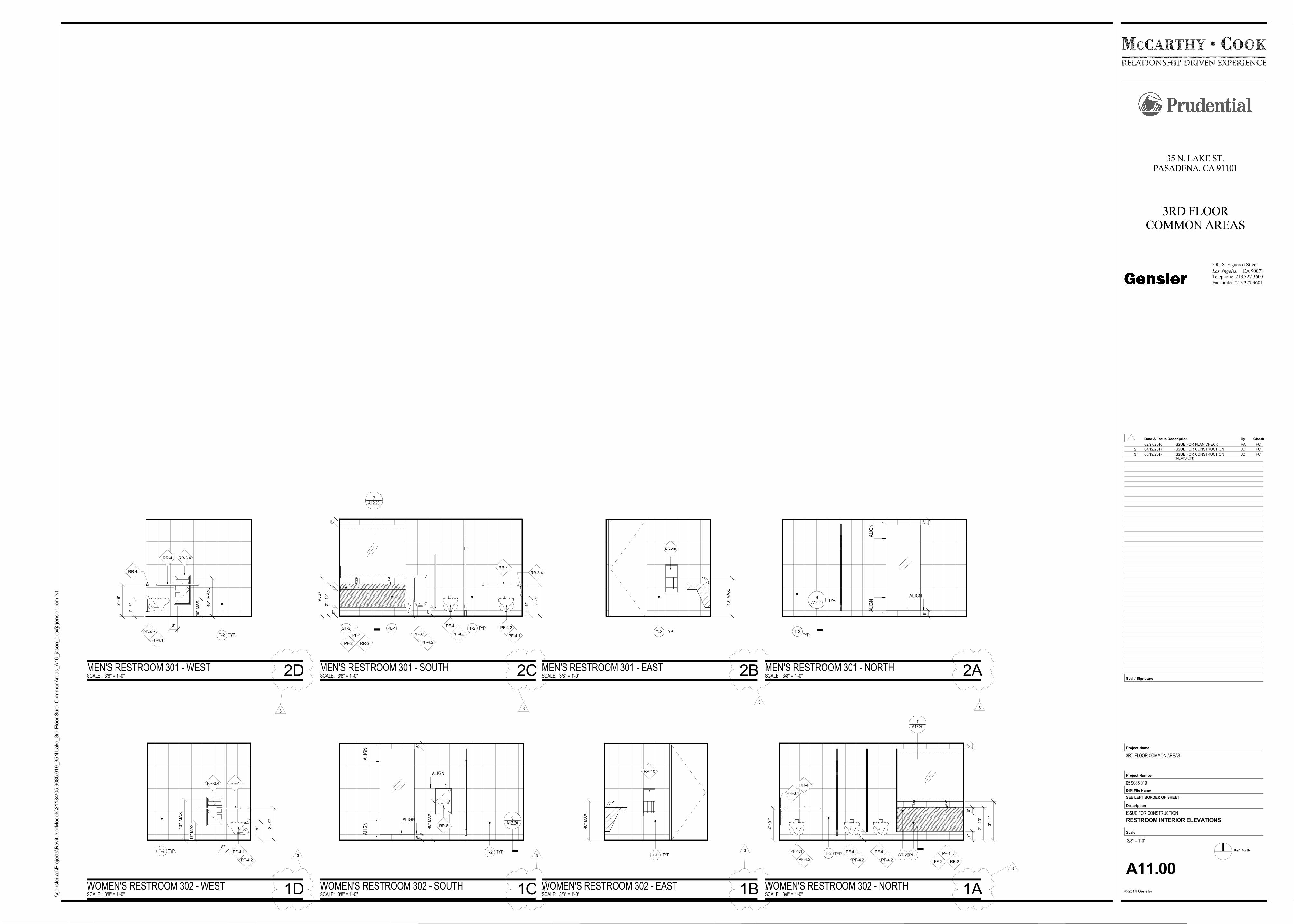
40"
MA
X.
T-2
RR-10
6"
6"
ALIGN
ALIGN
40"
MA
X.
T-2
9A12.20
________________
ALI
GN
ALI
GN
TYP.
RR-8
40"
MA
X.
RR-10
1' -
6"2' -
9"
8"
19"
MA
X.
40
" M
AX
.
RR-4
PF-4.2
PF-4.1
RR-3.4RR-4
T-2 TYP.
ALIGN
ALI
GN
6"
6"A
LIG
N
T-2
9A12.20
________________TYP.
T-2
2' -
9"
1'-
6"
8"
19"
MA
X.
40
" M
AX
.
PF-4.2
PF-4.1
RR-3.4 RR-4
1'-
6" 2' -
9"
9"
6"
3' -
4"
1' -
5"2' -
10"
6"
9"
7A12.20
________________
ST-2 PL-1 T-2 TYP. PF-4.2
PF-4.1
RR-3.4
RR-4
PF-4
PF-4.2PF-3.1
PF-4.2PF-2
PF-1
RR-2
6"
9"
9"
2' -
10"
6"
3' -
4"
2'-
9"
7A12.20
________________
PL-1ST-2
RR-4
PF-4.2
PF-4.1 PF-4
PF-4.2
PF-4
PF-4.2
RR-3.4
PF-2
PF-1
RR-2
Ref. North
CA 90071Los Angeles,
2014 Gensler
Project Number
BIM File Name
Scale
Description
c
Project Name
Seal / Signature
Check
Facsimile 213.327.3601
Telephone 213.327.3600
Date & By
500 S. Figueroa Street
Issue Description
SEE LEFT BORDER OF SHEET
\\ge
nsl
er.
ad\P
roje
cts
\RevitU
serM
od
els
\21
184
\05
.90
85.0
19
_35
N L
ake
_3rd
Flo
or
Su
ite C
om
mo
nA
reas_A
16_ja
son_o
pp@
gen
sle
r.com
.rvt
3/8" = 1'-0"
35 N. LAKE ST.PASADENA, CA 91101
3RD FLOORCOMMON AREAS
3RD FLOOR COMMON AREAS
05.9085.019
ISSUE FOR CONSTRUCTION
A11.00
RESTROOM INTERIOR ELEVATIONS
SCALE: 3/8" = 1'-0"
WOMEN'S RESTROOM 302 - EAST 1BSCALE: 3/8" = 1'-0"
WOMEN'S RESTROOM 302 - SOUTH 1C
SCALE: 3/8" = 1'-0"
MEN'S RESTROOM 301 - EAST 2BSCALE: 3/8" = 1'-0"
MEN'S RESTROOM 301 - WEST 2D SCALE: 3/8" = 1'-0"
MEN'S RESTROOM 301 - NORTH 2A
SCALE: 3/8" = 1'-0"
WOMEN'S RESTROOM 302 - WEST 1D
SCALE: 3/8" = 1'-0"
MEN'S RESTROOM 301 - SOUTH 2C
SCALE: 3/8" = 1'-0"
WOMEN'S RESTROOM 302 - NORTH 1A
T-2 TYP.TYP.TYP.
TYP.T-2 TYP.
02/27/2016 ISSUE FOR PLAN CHECK RA FC
2 04/12/2017 ISSUE FOR CONSTRUCTION JO FC
3 06/19/2017 ISSUE FOR CONSTRUCTION(REVISION)
JO FC
33
3
3
3 33
3
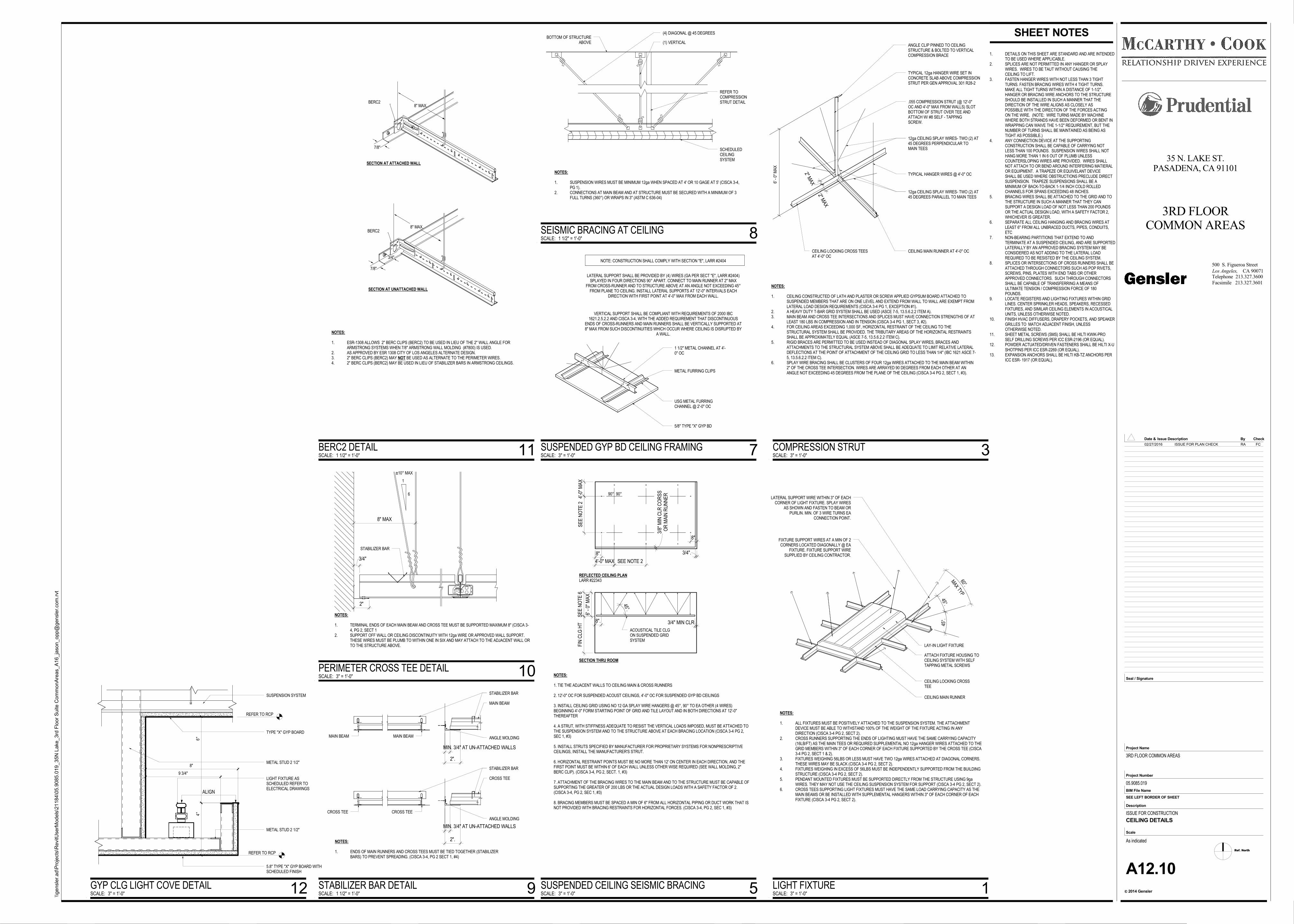
8".
4'-0" MAX SEE NOTE 2
SE
E N
OTE
24'
-0" M
AX
8".
3/4".
OR
MA
IN R
UN
NE
R3/
8" M
IN C
LR C
OR
SS
NOTES:
1. TIE THE ADJACENT WALLS TO CEILING MAIN & CROSS RUNNERS
2. 12'-0" OC FOR SUSPENDED ACOUST CEILINGS, 4'-0" OC FOR SUSPENDED GYP BD CEILINGS
3. INSTALL CEILING GRID USING NO 12 GA SPLAY WIRE HANGERS @ 45°, 90° TO EA OTHER (4 WIRES)BEGINNING 4'-0" FORM STARTING POINT OF GRID AND TILE LAYOUT AND IN BOTH DIRECTIONS AT 12'-0"THEREAFTER
4. A STRUT, WITH STIFFNESS ADEQUATE TO RESIST THE VERTICAL LOADS IMPOSED, MUST BE ATTACHED TOTHE SUSPENSION SYSTEM AND TO THE STRUCTURE ABOVE AT EACH BRACING LOCATION (CISCA 3-4 PG 2,SEC 1, #3)
5. INSTALL STRUTS SPECIFIED BY MANUFACTURER FOR PROPRIETARY SYSTEMS FOR NONPRESCRIPTIVECEILINGS, INSTALL THE MANUFACTURER'S STRUT.
6. HORIZONTAL RESTRAINT POINTS MUST BE NO MORE THAN 12' ON CENTER IN EACH DIRECTION, AND THEFIRST POINT MUST BE WITHIN 6' OF EACH WALL UNLESS OTHER WISE REQUIRED (SEE WALL MOLDING, 2"BERC CLIP). (CISCA 3-4, PG 2, SECT. 1, #3)
7. ATTACHMENT OF THE BRACING WIRES TO THE MAIN BEAM AND TO THE STRUCTURE MUST BE CAPABLE OFSUPPORTING THE GREATER OF 200 LBS OR THE ACTUAL DESIGN LOADS WITH A SAFETY FACTOR OF 2.(CISCA 3-4, PG 2, SEC 1, #3)
8. BRACING MEMBERS MUST BE SPACED A MIN OF 6" FROM ALL HORIZONTAL PIPING OR DUCT WORK THAT ISNOT PROVIDED WITH BRACING RESTRAINTS FOR HORIZONTAL FORCES. (CISCA 3-4, PG 2, SEC 1, #3)
90° 90°
FIN
CLG
HT 8".
ACOUSTICAL TILE CLGON SUSPENDED GRIDSYSTEM
3/4" MIN CLR
REFLECTED CEILING PLANLARR #22343
SECTION THRU ROOM
45°.
SE
E N
OTE
6
6' -
0" M
AX
NOTE: CONSTRUCTION SHALL COMPLY WITH SECTION "E", LARR #2404
LATERAL SUPPORT SHALL BE PROVIDED BY (4) WIRES (GA PER SECT "E", LARR #2404)SPLAYED IN FOUR DIRECTIONS 90° APART. CONNECT TO MAIN RUNNER AT 2" MAX
FROM CROSS-RUNNER AND TO STRUCTURE ABOVE AT AN ANGLE NOT EXCEEDING 45°FROM PLANE TO CEILING. INSTALL LATERAL SUPPORTS AT 12'-0" INTERVALS EACH
DIRECTION WITH FIRST POINT AT 4'-0" MAX FROM EACH WALL.
VERTICAL SUPPORT SHALL BE COMPLIANT WITH REQUIREMENTS OF 2000 IBC1621.2.5.2.2 AND CISCA 3-4, WITH THE ADDED REQUIREMENT THAT DISCONTINUOUS
ENDS OF CROSS-RUNNERS AND MAIN RUNNERS SHALL BE VERTICALLY SUPPORTED AT8" MAX FROM SUCH DISCONTINUITIES WHICH OCCUR WHERE CEILING IS DISRUPTED BY
A WALL.
1 1/2" METAL CHANNEL AT 4'-0" OC
METAL FURRING CLIPS
USG METAL FURRINGCHANNEL @ 2'-0" OC
5/8" TYPE "X" GYP BD
REFER TOCOMPRESSIONSTRUT DETAIL
(1) VERTICAL
(4) DIAGONAL @ 45 DEGREESBOTTOM OF STRUCTURE
ABOVE
SCHEDULEDCEILINGSYSTEM
NOTES:
1. SUSPENSION WIRES MUST BE MINIMUM 12ga WHEN SPACED AT 4' OR 10 GAGE AT 5' (CISCA 3-4,PG 1).
2. CONNECTIONS AT MAIN BEAM AND AT STRUCTURE MUST BE SECURED WITH A MINIMUM OF 3FULL TURNS (360°) OR WRAPS IN 3" (ASTM C 636-04)
MAIN BEAM
STABILIZER BAR
ANGLE MOLDINGMAIN BEAM
CROSS TEE
MAIN BEAM
CROSS TEE
NOTES:
1. ENDS OF MAIN RUNNERS AND CROSS TEES MUST BE TIED TOGETHER (STABILIZERBARS) TO PREVENT SPREADING. (CISCA 3-4, PG 2 SECT 1, #4)
MIN. 3/4" AT UN-ATTACHED WALLS
2".
CROSS TEE
STABILIZER BAR
ANGLE MOLDING
MIN. 3/4" AT UN-ATTACHED WALLS
2".
6
1
±10° MAX
STABILIZER BAR
NOTES:
1. TERMINAL ENDS OF EACH MAIN BEAM AND CROSS TEE MUST BE SUPPORTED MAXIMUM 8" (CISCA 3-4, PG 2, SECT 1
2. SUPPORT OFF WALL OR CEILING DISCONTINUITY WITH 12ga WIRE OR APPROVED WALL SUPPORT.THESE WIRES MUST BE PLUMB TO WITHIN ONE IN SIX AND MAY ATTACH TO THE ADJACENT WALL ORTO THE STRUCTURE ABOVE.
3/4"
2"
8" MAX
8" MAX.
7/8"
BERC2
SECTION AT ATTACHED WALL
7/8"
8" MAX.
3/4"
BERC2
SECTION AT UNATTACHED WALL
NOTES:
1. ESR-1308 ALLOWS 2" BERC CLIPS (BERC2) TO BE USED IN LIEU OF THE 2" WALL ANGLE FORARMSTRONG SYSTEMS WHEN 7/8" ARMSTRONG WALL MOLDING (#7800) IS USED.
2. AS APPROVED BY ESR 1308 CITY OF LOS ANGELES ALTERNATE DESIGN.3. 2" BERC CLIPS (BERC2) MAY NOT BE USED AS ALTERNATE TO THE PERIMETER WIRES.4. 2" BERC CLIPS (BERC2) MAY BE USED IN LIEU OF STABILIZER BARS IN ARMSTRONG CEILINGS.
1. DETAILS ON THIS SHEET ARE STANDARD AND ARE INTENDEDTO BE USED WHERE APPLICABLE.
2. SPLICES ARE NOT PERMITTED IN ANY HANGER OR SPLAYWIRES. WIRES TO BE TAUT WITHOUT CAUSING THECEILING TO LIFT.
3. FASTEN HANGER WIRES WITH NOT LESS THAN 3 TIGHTTURNS. FASTEN BRACING WIRES WITH 4 TIGHT TURNS.MAKE ALL TIGHT TURNS WITHIN A DISTANCE OF 1-1/2".HANGER OR BRACING WIRE ANCHORS TO THE STRUCTURESHOULD BE INSTALLED IN SUCH A MANNER THAT THEDIRECTION OF THE WIRE ALIGNS AS CLOSELY ASPOSSIBLE WITH THE DIRECTION OF THE FORCES ACTINGON THE WIRE. (NOTE: WIRE TURNS MADE BY MACHINEWHERE BOTH STRANDS HAVE BEEN DEFORMED OR BENT INWRAPPING CAN WAIVE THE 1-1/2" REQUIREMENT, BUT THENUMBER OF TURNS SHALL BE MAINTAINED AS BEING ASTIGHT AS POSSIBLE.)
4. ANY CONNECTION DEVICE AT THE SUPPORTINGCONSTRUCTION SHALL BE CAPABLE OF CARRYING NOTLESS THAN 100 POUNDS. SUSPENSION WIRES SHALL NOTHANG MORE THAN 1 IN 6 OUT OF PLUMB UNLESSCOUNTERSLOPING WIRES ARE PROVIDED. WIRES SHALLNOT ATTACH TO OR BEND AROUND INTERFERING MATIERALOR EQUIPMENT. A TRAPEZE OR EQUIVELANT DEVICESHALL BE USED WHERE OBSTRUCTIONS PRECLUDE DIRECTSUSPENSION. TRAPEZE SUSPENSIONS SHALL BE AMINIMUM OF BACK-TO-BACK 1-1/4 INCH COLD ROLLEDCHANNELS FOR SPANS EXCEEDING 48 INCHES.
5. BRACING WIRES SHALL BE ATTACHED TO THE GRID AND TOTHE STRUCTURE IN SUCH A MANNER THAT THEY CANSUPPORT A DESIGN LOAD OF NOT LESS THAN 200 POUNDSOR THE ACTUAL DESIGN LOAD, WITH A SAFETY FACTOR 2,WHICHEVER IS GREATER.
6. SEPARATE ALL CEILING HANGING AND BRACING WIRES ATLEAST 6" FROM ALL UNBRACED DUCTS, PIPES, CONDUITS,ETC
7. NON-BEARING PARTITIONS THAT EXTEND TO ANDTERMINATE AT A SUSPENDED CEILING, AND ARE SUPPORTEDLATERALLY BY AN APPROVED BRACING SYSTEM MAY BECONSIDERED AS NOT ADDING TO THE LATERAL LOADREQUIRED TO BE RESISTED BY THE CEILING SYSTEM.
8. SPLICES OR INTERSECTIONS OF CROSS RUNNERS SHALL BEATTACHED THROUGH CONNECTORS SUCH AS POP RIVETS,SCREWS, PINS, PLATES WITH END TABS OR OTHERAPPROVED CONNECTORS. SUCH THROUGH CONNECTORSSHALL BE CAPABLE OF TRANSFERRING A MEANS OFULTIMATE TENSION / COMPRESSION FORCE OF 180POUNDS.
9. LOCATE REGISTERS AND LIGHTING FIXTURES WITHIN GRIDLINES. CENTER SPRINKLER HEADS, SPEAKERS, RECESSEDFIXTURES, AND SIMILAR CEILING ELEMENTS IN ACOUSTICALUNITS, UNLESS OTHERWISE NOTED.
10. FINISH HVAC DIFFUSERS, DRAPERY POCKETS, AND SPEAKERGRILLES TO MATCH ADJACENT FINISH, UNLESSOTHERWISE NOTED.
11. SHEET METAL SCREWS (SMS) SHALL BE HILTI KWIK-PROSELF DRILLING SCREWS PER ICC ESR-2196 (OR EQUAL).
12. POWDER ACTUATED/DRIVEN FASTENERS SHALL BE HILTI X-USHOTPINS PER ICC ESR-2269 (OR EQUAL).
13. EXPANSION ANCHORS SHALL BE HILTI KB-TZ ANCHORS PERICC ESR- 1917 (OR EQUAL).
4"
6"
8"
REFER TO RCP
REFER TO RCP
9 3/4"
ALIGN
SUSPENSION SYSTEM
TYPE "X" GYP BOARD
METAL STUD 2 1/2"
LIGHT FIXTURE ASSCHEDULED REFER TOELECTRICAL DRAWINGS
METAL STUD 2 1/2"
5.8" TYPE "X" GYP BOARD WITHSCHEDULED FINISH
45°.
45°.
MAX TYP
60°.
LATERAL SUPPORT WIRE WITHIN 3" OF EACHCORNER OF LIGHT FIXTURE. SPLAY WIRES
AS SHOWN AND FASTEN TO BEAM ORPURLIN. MIN. OF 3 WIRE TURNS EA
CONNECTION POINT.
FIXTURE SUPPORT WIRES AT A MIN OF 2CORNERS LOCATED DIAGONALLY @ EA
FIXTURE. FIXTURE SUPPORT WIRESUPPLIED BY CEILING CONTRACTOR.
CEILING MAIN RUNNER
CEILING LOCKING CROSSTEE
LAY-IN LIGHT FIXTURE
ATTACH FIXTURE HOUSING TOCEILING SYSTEM WITH SELFTAPPING METAL SCREWS
NOTES:
1. ALL FIXTURES MUST BE POSITIVELY ATTACHED TO THE SUSPENSION SYSTEM. THE ATTACHMENTDEVICE MUST BE ABLE TO WITHSTAND 100% OF THE WEIGHT OF THE FIXTURE ACTING IN ANYDIRECTION (CISCA 3-4 PG 2, SECT 2).
2. CROSS RUNNERS SUPPORTING THE ENDS OF LIGHTING MUST HAVE THE SAME CARRYING CAPACITY(16LB/FT) AS THE MAIN TEES OR REQUIRED SUPPLEMENTAL NO 12ga HANGER WIRES ATTACHED TO THEGRID MEMBERS WITHIN 3" OF EACH CORNER OF EACH FIXTURE SUPPORTED BY THE CROSS TEE (CISCA3-4 PG 2, SECT 1 & 2).
3. FIXTURES WEIGHING 56LBS OR LESS MUST HAVE TWO 12ga WIRES ATTACHED AT DIAGONAL CORNERS.THESE WIRES MAY BE SLACK (CISCA 3-4 PG 2, SECT 2).
4. FIXTURES WEIGHING IN EXCESS OF 56LBS MUST BE INDEPENDENTLY SUPPORTED FROM THE BUILDINGSTRUCTURE (CISCA 3-4 PG 2, SECT 2).
5. PENDANT MOUNTED FIXTURES MUST BE SUPPORTED DIRECTLY FROM THE STRUCTURE USING 9gaWIRES. THEY MAY NOT USE THE CEILING SUSPENSION SYSTEM FOR SUPPORT (CISCA 3-4 PG 2, SECT 2).
6. CROSS TEES SUPPORTING LIGHT FIXTURES MUST HAVE THE SAME LOAD CARRYING CAPACITY AS THEMAIN BEAMS OR BE INSTALLED WITH SUPPLEMENTAL HANGERS WITHIN 3" OF EACH CORNER OF EACHFIXTURE (CISCA 3-4 PG 2, SECT 2).
2" MAX
2" MAX
ANGLE CLIP PINNED TO CEILINGSTRUCTURE & BOLTED TO VERTICALCOMPRESSION BRACE
TYPICAL 12ga HANGER WIRE SET INCONCRETE SLAB ABOVE COMPRESSIONSTRUT PER GEN APPROVAL 301 R28-2
.055 COMPRESSION STRUT (@ 12'-0"OC AND 4'-0" MAX FROM WALLS) SLOTBOTTOM OF STRUT OVER TEE ANDATTACH W/ #8 SELF - TAPPINGSCREW.
12ga CEILING SPLAY WIRES- TWO (2) AT45 DEGREES PERPENDICULAR TOMAIN TEES
12ga CEILING SPLAY WIRES- TWO (2) AT45 DEGREES PARALLEL TO MAIN TEES
TYPICAL HANGER WIRES @ 4'-0" OC
CEILING MAIN RUNNER AT 4'-0" OCCEILING LOCKING CROSS TEESAT 4'-0" OC
NOTES:
1. CEILING CONSTRUCTED OF LATH AND PLASTER OR SCREW APPLIED GYPSUM BOARD ATTACHED TOSUSPENDED MEMBERS THAT ARE ON ONE LEVEL AND EXTEND FROM WALL TO WALL ARE EXEMPT FROMLATERAL LOAD DESIGN REQUIREMENTS (CISCA 3-4 PG 1, EXCEPTION #1).
2. A HEAVY DUTY T-BAR GRID SYSTEM SHALL BE USED (ASCE 7-5, 13.5.6.2.2 ITEM A).3. MAIN BEAM AND CROSS TEE INTERSECTIONS AND SPLICES MUST HAVE CONNECTION STRENGTHS OF AT
LEAST 180 LBS IN COMPRESSION AND IN TENSION (CISCA 3-4 PG 1, SECT 3, #2).4. FOR CEILING AREAS EXCEEDING 1,000 SF, HORIZONTAL RESTRAINT OF THE CEILING TO THE
STRUCTURAL SYSTEM SHALL BE PROVIDED. THE TRIBUTARY AREAS OF THE HORIZONTAL RESTRAINTSSHALL BE APPROXIMATELY EQUAL (ASCE 7-5, 13.5.6.2.2 ITEM C).
5. RIGID BRACES ARE PERMITTED TO BE USED INSTEAD OF DIAGONAL SPLAY WIRES, BRACES ANDATTACHMENTS TO THE STRUCTURAL SYSTEM ABOVE SHALL BE ADEQUATE TO LIMIT RELATIVE LATERALDEFLECTIONS AT THE POINT OF ATTACHMENT OF THE CEILING GRID TO LESS THAN 1/4" (IBC 1621 ASCE 7-5, 13.5.6.2.2 ITEM C).
6. SPLAY WIRE BRACING SHALL BE CLUSTERS OF FOUR 12ga WIRES ATTACHED TO THE MAIN BEAM WITHIN2" OF THE CROSS TEE INTERSECTION. WIRES ARE ARRAYED 90 DEGREES FROM EACH OTHER AT ANANGLE NOT EXCEEDING 45 DEGREES FROM THE PLANE OF THE CEILING (CISCA 3-4 PG 2, SECT 1, #3).
6' -
0" M
AX
SHEET NOTES
Ref. North
CA 90071Los Angeles,
2014 Gensler
Project Number
BIM File Name
Scale
Description
c
Project Name
Seal / Signature
Check
Facsimile 213.327.3601
Telephone 213.327.3600
Date & By
500 S. Figueroa Street
Issue Description
SEE LEFT BORDER OF SHEET
\\ge
nsl
er.
ad\P
roje
cts
\RevitU
serM
od
els
\21
184
\05
.90
85.0
19
_35
N L
ake
_3rd
Flo
or
Su
ite C
om
mo
nA
reas_A
16_ja
son_o
pp@
gen
sle
r.com
.rvt
As indicated
35 N. LAKE ST.PASADENA, CA 91101
3RD FLOORCOMMON AREAS
3RD FLOOR COMMON AREAS
05.9085.019
ISSUE FOR CONSTRUCTION
A12.10
CEILING DETAILS
SCALE: 3" = 1'-0"
SUSPENDED CEILING SEISMIC BRACING 5
SCALE: 3" = 1'-0"
SUSPENDED GYP BD CEILING FRAMING 7
SCALE: 1 1/2" = 1'-0"
SEISMIC BRACING AT CEILING 8
SCALE: 1 1/2" = 1'-0"
STABILIZER BAR DETAIL 9
SCALE: 3" = 1'-0"
PERIMETER CROSS TEE DETAIL 10
SCALE: 1 1/2" = 1'-0"
BERC2 DETAIL 11
SCALE: 3" = 1'-0"
GYP CLG LIGHT COVE DETAIL 12 SCALE: 3" = 1'-0"
LIGHT FIXTURE 1
SCALE: 3" = 1'-0"
COMPRESSION STRUT 302/27/2016 ISSUE FOR PLAN CHECK RA FC
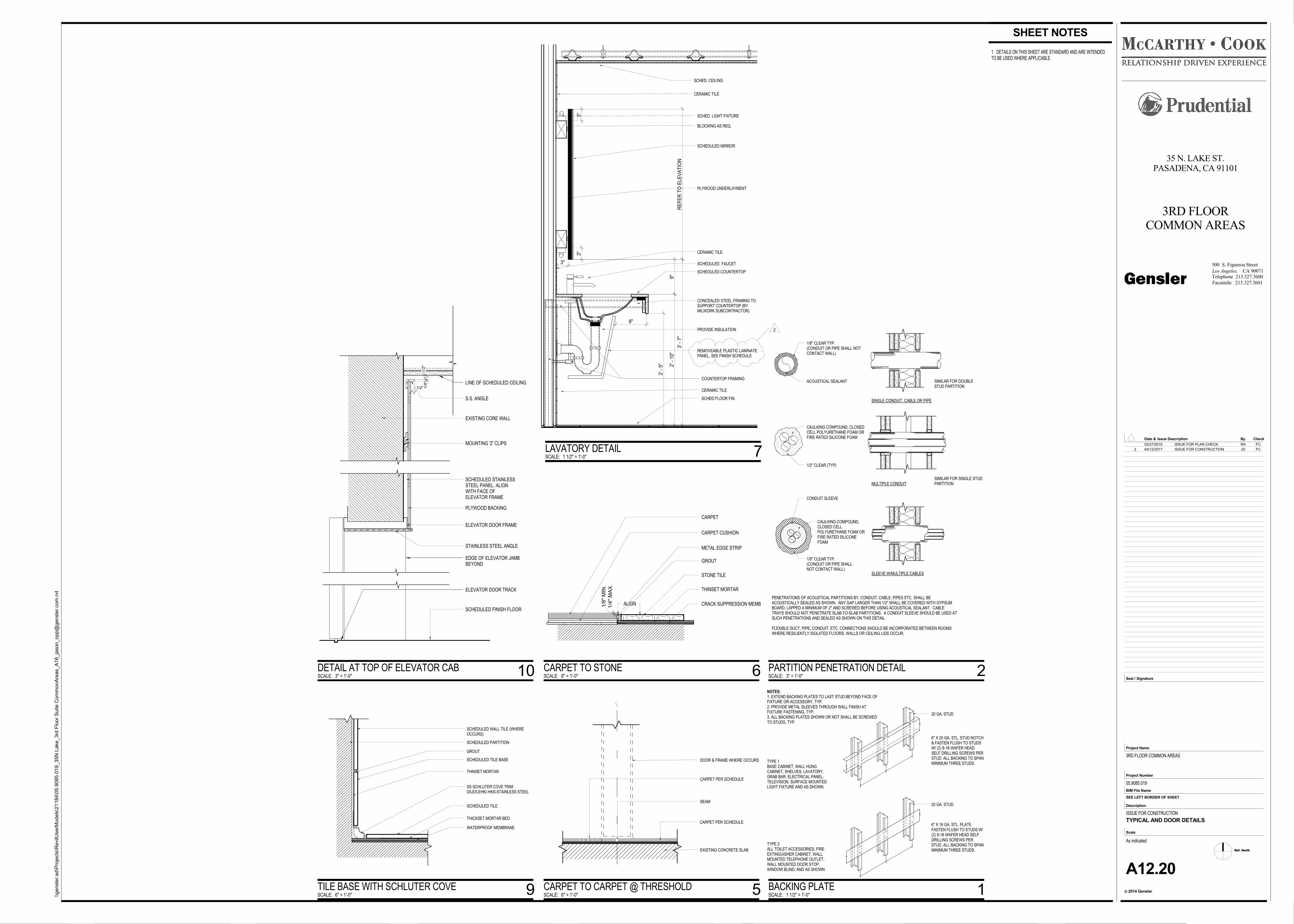
NOTES:1. EXTEND BACKING PLATES TO LAST STUD BEYOND FACE OFFIXTURE OR ACCESSORY, TYP.2. PROVIDE METAL SLEEVES THROUGH WALL FINISH ATFIXTURE FASTENING, TYP.3. ALL BACKING PLATES SHOWN OR NOT SHALL BE SCREWEDTO STUDS, TYP.
6" X 20 GA. STL. STUD NOTCH& FASTEN FLUSH TO STUDSW/ (2) 8-18 WAFER HEADSELF DRILLING SCREWS PERSTUD. ALL BACKING TO SPANMINIMUM THREE STUDS.
20 GA. STUD
20 GA. STUD
TYPE 2ALL TOILET ACCESSORIES, FIREEXTINGUISHER CABINET, WALLMOUNTED TELEPHONE OUTLET,WALL MOUNTED DOOR STOP,WINDOW BLIND, AND AS SHOWN.
TYPE 1BASE CABINET, WALL HUNGCABINET, SHELVES, LAVATORY,GRAB BAR, ELECTRICAL PANEL,TELEVISION, SURFACE MOUNTEDLIGHT FIXTURE AND AS SHOWN.
6" X 16 GA. STL. PLATEFASTEN FLUSH TO STUDS W/(2) 8-18 WAFER HEAD SELFDRILLING SCREWS PERSTUD. ALL BACKING TO SPANMINIMUM THREE STUDS.
SINGLE CONDUIT, CABLE OR PIPE
MULTIPLE CONDUIT
SLEEVE W/MULTIPLE CABLES
SIMILAR FOR SINGLE STUDPARTITION
SIMILAR FOR DOUBLESTUD PARTITION
PENETRATIONS OF ACOUSTICAL PARTITIONS BY, CONDUIT, CABLE, PIPES ETC. SHALL BEACOUSTICALLY SEALED AS SHOWN. ANY GAP LARGER THAN 1/2" SHALL BE COVERED WITH GYPSUMBOARD, LAPPED A MINIMUM OF 2" AND SCREWED BEFORE USING ACOUSTICAL SEALANT. CABLETRAYS SHOULD NOT PENETRATE SLAB-TO-SLAB PARTITIONS. A CONDUIT SLEEVE SHOULD BE USED ATSUCH PENETRATIONS AND SEALED AS SHOWN ON THIS DETAIL.
FLEXIBLE DUCT, PIPE, CONDUIT, ETC. CONNECTIONS SHOULD BE INCORPORATED BETWEEN ROOMSWHERE RESILIENTLY ISOLATED FLOORS, WALLS OR CEILING LIDS OCCUR.
1/8" CLEAR TYP.(CONDUIT OR PIPE SHALL NOTCONTACT WALL)
ACOUSTICAL SEALANT
CAULKING COMPOUND, CLOSEDCELL POLYURETHANE FOAM ORFIRE RATED SILICONE FOAM
1/2" CLEAR (TYP)
CONDUIT SLEEVE
1/8" CLEAR TYP.(CONDUIT OR PIPE SHALLNOT CONTACT WALL)
CAULKING COMPOUND,CLOSED CELLPOLYURETHANE FOAM ORFIRE RATED SILICONEFOAM
1. DETAILS ON THIS SHEET ARE STANDARD AND ARE INTENDEDTO BE USED WHERE APPLICABLE.
2' -
10"
8"
2' -
5"
3' -
7"
RE
FE
R T
O E
LEV
AT
ION
PROVIDE INSULATION
SCHEDULED FAUCET
SCHEDULED COUNTERTOP
SCHEDULED MIRROR
PLYWOOD UNDERLAYMENT
BLOCKING AS REQ.
CONCEALED STEEL FRAMING TOSUPPORT COUNTERTOP (BYMILWORK SUBCONTRACTOR)
CERAMIC TILE
CERAMIC TILE
SCHED FLOOR FIN.
COUNTERTOP FRAMING
REMOVEABLE PLASTIC LAMINATEPANEL, SEE FINISH SCHEDULE
3"
SCHED. LIGHT FIXTURE
9"
3"3"
SCHED. CEILING
CERAMIC TILE
EXISTING CORE WALL
SCHEDULED FINISH FLOOR
SCHEDULED STAINLESSSTEEL PANEL. ALIGNWITH FACE OFELEVATOR FRAME
PLYWOOD BACKING
ELEVATOR DOOR FRAME
MOUNTING 'Z' CLIPS
1/2"
1/2
"1/4
"
S.S. ANGLE
STAINLESS STEEL ANGLE
ELEVATOR DOOR TRACK
EDGE OF ELEVATOR JAMBBEYOND
LINE OF SCHEDULED CEILING
WATERPROOF MEMBRANE
THICKSET MORTAR BED
SCHEDULED TILE
GROUT
THINSET MORTAR
SCHEDULED TILE BASE
SCHEDULED WALL TILE (WHEREOCCURS)
SCHEDULED PARTITION
SS SCHLUTER COVE TRIMDILEX-EHK/-HKS-STAINLESS STEEL
CARPET
CARPET CUSHION
METAL EDGE STRIP
GROUT
STONE TILE
THINSET MORTAR
CRACK SUPPRESSION MEMBALIGN1/4
" M
AX
.1/8
" M
IN.
SEAM
CARPET PER SCHEDULE
CARPET PER SCHEDULE
EXISTING CONCRETE SLAB
DOOR & FRAME WHERE OCCURS
Ref. North
CA 90071Los Angeles,
2014 Gensler
Project Number
BIM File Name
Scale
Description
c
Project Name
Seal / Signature
Check
Facsimile 213.327.3601
Telephone 213.327.3600
Date & By
500 S. Figueroa Street
Issue Description
SEE LEFT BORDER OF SHEET
\\ge
nsl
er.
ad\P
roje
cts
\RevitU
serM
od
els
\21
184
\05
.90
85.0
19
_35
N L
ake
_3rd
Flo
or
Su
ite C
om
mo
nA
reas_A
16_ja
son_o
pp@
gen
sle
r.com
.rvt
As indicated
35 N. LAKE ST.PASADENA, CA 91101
3RD FLOORCOMMON AREAS
3RD FLOOR COMMON AREAS
05.9085.019
ISSUE FOR CONSTRUCTION
A12.20
TYPICAL AND DOOR DETAILS
SCALE: 1 1/2" = 1'-0"
BACKING PLATE 1
SCALE: 3" = 1'-0"
PARTITION PENETRATION DETAIL 2
SHEET NOTES
SCALE: 1 1/2" = 1'-0"
LAVATORY DETAIL 7
SCALE: 3" = 1'-0"
DETAIL AT TOP OF ELEVATOR CAB 10
SCALE: 6" = 1'-0"
TILE BASE WITH SCHLUTER COVE 9
SCALE: 6" = 1'-0"
CARPET TO STONE 6
SCALE: 6" = 1'-0"
CARPET TO CARPET @ THRESHOLD 5
02/27/2016 ISSUE FOR PLAN CHECK RA FC
2 04/12/2017 ISSUE FOR CONSTRUCTION JO FC
2
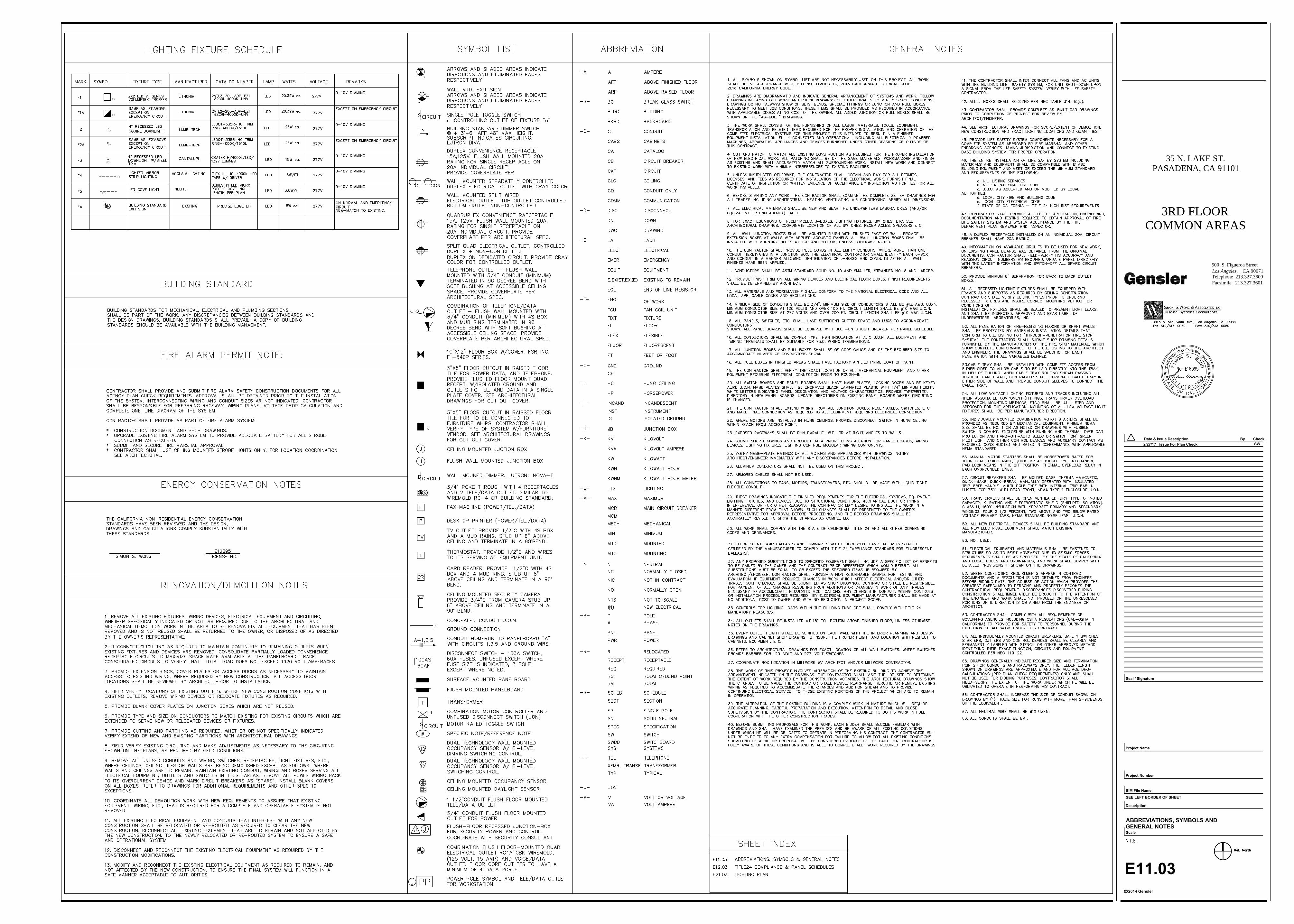
D
F1
F1
F2
F2
F3
F4
F5
E11.03
ABBREVIATIONS, SYMBOLS AND
GENERAL NOTES
CA 90071Los Angeles,
2014 Gensler
Project Number
BIM File Name
Scale
Description
c
Project Name
Seal / Signature
Check
Facsimile 213.327.3601Telephone 213.327.3600
Date & By
500 S. Figueroa Street
Issue Description
SEE LEFT BORDER OF SHEET
35 N. LAKE ST.PASADENA, CA 91101
3RD FLOORCOMMON AREAS
SW
Issue For Plan Check2/27/17
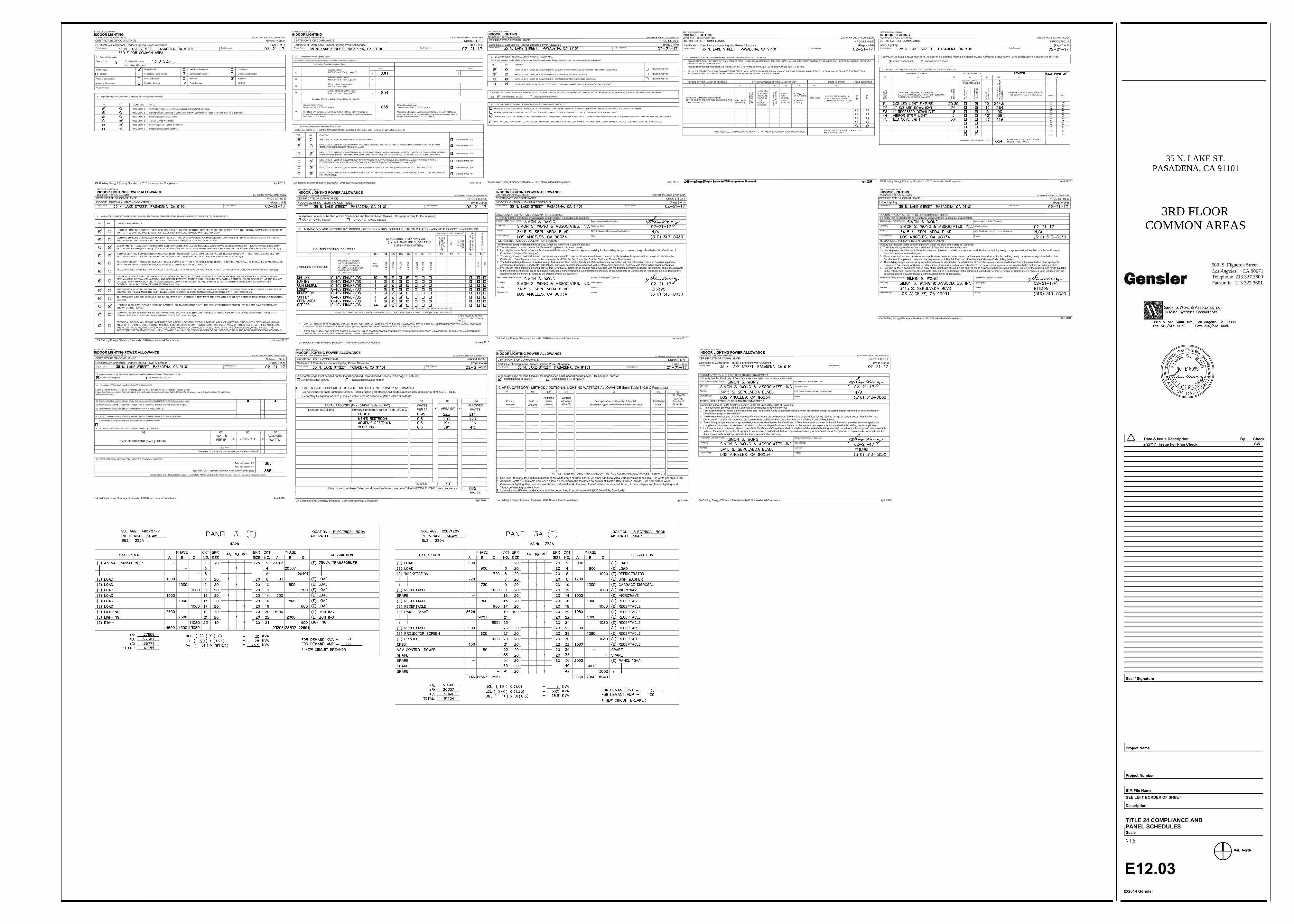
THE ACTUAL INDOOR LIGHTING POWER LISTED ON THE NEXT 2 PAGES INCLUDES ALL INSTALLED PERMANENT AND PLANNED PORTABLE LIGHTING SYSTEMS.
ALSO INCLUDE TRACK LIGHTING IN SCHEDULE, AND SUBMIT THE TRACK LIGHTING COMPLIANCE DOCUMENT (NRCC-LTI-05-E) WHEN LINE-VOLTAGE TRACK LIGHTING IS INSTALLED.
STATE OF CALIFORNIA
INDOOR LIGHTING
CEC-NRCC-LTI-01-E (Revised 04/16)
CALIFORNIA ENERGY COMMISSION
CERTIFICATE OF COMPLIANCE
NRCC-LTI-01-E
Certificate of Compliance - Indoor Lighting Power Allowance(Page 1 of 6)
Project Name: Date Prepared:
A. General Information
Climate Zone:Conditioned Floor Area:
Unconditioned Floor Area:
Building Type:
Schools
Phase of Construction:
Method of Compliance:
Nonresidential
Relocatable Public Schools
New Construction
Complete Building
High-Rise Residential
Conditioned Spaces
Addition
Area Category
Hotel/Motel
Unconditioned Spaces
Alteration
Tailored
Project Address:
B. Lighting Compliance Documents (select yes for each document included)
YES NOCOMP DOC TITLE
NRCC-LTI-01-E
NRCC-LTI-02-E
NRCC-LTI-03-E
NRCC-LTI-04-E
NRCC-LTI-05-E
NRCC-LTI-06-E
Certificate of Compliance. All Pages required on plans for all submittals.
Lighting Controls, Certificate of Compliance, and PAF Calculation. All Pages required on plans for all submittals.
Indoor Lighting Power Allowance
Tailored Method Worksheets
Line Voltage Track Lighting Worksheets
Indoor Lighting Existing Conditions
CA Building Energy Efficiency Standards - 2016 Nonresidential Compliance April 2016
STATE OF CALIFORNIA
INDOOR LIGHTING
CEC-NRCC-LTI-01-E (Revised 04/16)
CALIFORNIA ENERGY COMMISSION
CERTIFICATE OF COMPLIANCE
NRCC-LTI-01-E
Certificate of Compliance - Indoor Lighting Power Allowance(Page 2 of 6)
Project Name: Date Prepared:
C. Summary of Allowed Lighting Power
Conditioned and Unconditioned space Lighting must not be combined for compliance
Indoor Lighting Power for Conditioned Spaces
WattsWatts
+
+
-
=
+
-
=
01
02
03
04
05
Installed Lighting
NRCC-LTI-01-E, Table H, page 5
Portable Only for Offices
NRCC-LTI-01-E, Table G, page 4
Minus Lighting Control Credits
NRCC-LTI-02-E, page 2
Adjusted Installed Lighting Power
(row 1 plus row 2 minus row 3)
Allowed Lighting Power
Conditioned NRCC-LTI-03-E, page 1
Alterations with replacement luminaires that have at least 50/35%lower power
compared to the original existing luminaires, may instead use the allowed wattage
form NRCC-LTI-06, page 2
Complies ONLY if Installed < Allowed (Box 04 < Box 05)
Allowed Lighting Power
Unconditioned NRCC-LTI-03-E, page 1
Alterations with replacement luminaires that have at least 50/35%lower
power compared to the original existing luminaires, may instead use the
allowed wattage form NRCC-LTI-06, page 2
D. Declaration of Required Certificates of Installation
Declare by selecting yes for all of the Certificates that will be submitted. (Retain copies and verify forms are completed and signed.)
YES NO Form/Title
NRCI-LTI-01-E - MUST BE SUBMITTED FOR ALL BUILDINGS
NRCI-LTI-02-E - MUST BE SUBMITTED FOR A LIGHTING CONTROL SYSTEM, OR FOR AN ENERGY MANAGEMENT CONTROL SYSTEM
(EMCS), TO BE RECOGNIZED FOR COMPLIANCE.
NRCI-LTI-03-E - MUST BE SUBMITTED FOR A LINE VOLTAGE TRACK LIGHTING INTEGRAL CURRENT LIMITER, OR FOR A SUPPLEMENTARY
OVERCURRENT PROTECTION PANEL USED TO ENERGIZE ONLY LINE VOLTAGE LIGHTING, TO BE RECOGNIZED FOR COMPLIANCE.
NRCI-LTI-04-E - MUST BE SUBMITTED FOR TWO INTERLOCKED SYSTEM SERVING AN AUDITORIUM, A CONVENTION CENTER, A
CONFERENCE ROOM, A MULTIPURPOSE ROOM, OR A THEATER TO BE RECOGNIZED FOR COMPLIANCE.
NRCI-LTI-05-E - MUST BE SUBMITTED FOR A POWER ADJUSTMENT FACTOR (PAF) TO BE RECOGNIZED FOR COMPLIANCE.
NRCI-LTI-06-E - MUST BE SUBMITTED FOR ADDITIONAL WATTAGE INSTALLED IN A VIDEO CONFERENCING STUDIO TO BE RECOGNIZED
FOR COMPLIANCE.
FIELD INSPECTOR
FIELD INSPECTOR
FIELD INSPECTOR
FIELD INSPECTOR
FIELD INSPECTOR
FIELD INSPECTOR
CA Building Energy Efficiency Standards - 2016 Nonresidential Compliance April 2016
CA Building Energy Efficiency Standards - 2016 Nonresidential Compliance April 2016
STATE OF CALIFORNIA
INDOOR LIGHTING
CEC-NRCC-LTI-01-E (Revised 04/16)
CALIFORNIA ENERGY COMMISSION
CERTIFICATE OF COMPLIANCE
NRCC-LTI-01-E
Certificate of Compliance - Indoor Lighting Power Allowance(Page 3 of 6)
Project Name: Date Prepared:
YES NO Form/Title
FIELD INSPECTOR
FIELD INSPECTOR
FIELD INSPECTOR
E. DECLARATION OF REQUIRED CERTIFICATES OF ACCEPTANCE
Declare by selecting yes for all of the Certificates that will be submitted. (Retain copies and verify forms are completed and signed.)
NRCA-LTI-02-A - MUST BE SUBMITTED FOR OCCUPANCY SENSORS AND AUTOMATIC TIME SWITCH CONTROLS.
NRCA-LTI-03-A - MUST BE SUBMITTED FOR AUTOMATIC DAYLIGHT CONTROLS.
NRCA-LTI-04-A - MUST BE SUBMITTED FOR DEMAND RESPONSIVE LIGHTING CONTROLS
NRCA-LTI-05-A- MUST BE SUBMITTED FOR INSTITUTIONAL TUNING POWER ADJUSTMENT FACTOR (PAF)
A SEPARATE LIGHTING SCHEDULE MUST BE FILLED OUT FOR CONDITIONED AND UNCONDITIONED SPACES. INSTALLED LIGHTING POWER LISTED ON THIS LIGHTING SCHEDULE IS ONLY
FOR:
CONDITIONED SPACE UNCONDITIONED SPACE
F. INDOOR LIGHTING SCHEDULE AND FIELD INSPECTION ENERGY CHECKLIST
WHEN COMPLETE BUILDING METHOD IS USED FOR COMPLIANCE, LIST EACH DIFFERENT TYPE OF LUMINAIRE ON SEPARATE LINES.
WHEN AREA CATEGORY METHOD OR TAILORED METHOD IS USED FOR COMPLIANCE, LIST EACH DIFFERENT TYPE OF LUMINAIRE BY EACH DIFFERENT FUNCTION AREA ON SEPARATE LINES
STATE OF CALIFORNIA
INDOOR LIGHTING
CEC-NRCC-LTI-01-E (Revised 04/16) CALIFORNIA ENERGY COMMISSION
CERTIFICATE OF COMPLIANCE
NRCC-LTI-01-E
Certificate of Compliance - Indoor Lighting Power Allowance(Page 4 of 6)
Project Name: Date Prepared:
G. INSTALLED PORTABLE LUMINAIRES IN OFFICES - EXCEPTION TO SECTION 140.6(a)
- THIS SECTION SHALL BE FILLED OUT ONLY FOR PORTABLE LUMINAIRES IN OFFICES (As DEFINED IN §100.1). ALL OTHER PLANNED PORTABLE LUMINAIRES SHALL BE DOCUMENTED ON NEXT PAGE
OF THIS COMPLIANCE DOCUMENT.
- THIS SECTION IS USED TO DETERMINE IF GREATER THAN 0.3 WATTS OF PORTABLE LIGHTING IS PLANNED FOR ANY OFFICE.
- FILL OUT A SEPARATE LINE FOR EACH DIFFERENT OFFICE. SMALL OFFICES THAT ARE TYPICAL (HAVING THE SAME GENERAL AND PORTABLE LIGHTING) MAY BE GROUPED TOGETHER. THIS
ALLOWANCE SHALL NOT BE TRADED BETWEEN OFFICES HAVING DIFFERENT LIGHTING SYSTEMS.
OFFICE PORTABLE LUMINAIRE SCHEDULE OFFICE INSTALLED PORTABLE LUMINAIRE W/FT OFFICE LOCATION FIELD INSPECTOR
01 02 03 04 05 06 07 08 09 10
TOTAL INSTALLED PORTABLE LUMINAIRE WATTS THAT ARE GREATER THAN 0.3W/FT PER OFFICE:
WATTS PER
LUMINAIRE
NU
MB
ER
O
F
LU
MIN
AIR
ES
INSTALLED
PORTABLE
LUMINAIRE
WATTS IN
THIS
OFFICE
(G04/G05)
SQ
UA
RE
F
EE
T
OF
T
HIS
O
FF
IC
E
WATTS
PER
SQUARE
FOOT
(G04/G05)
IF G06< 0.3,
ENTER ZERO;
IF G06 > 0.3,
(G06-0.3)
(G05 x G07)
IDENTIFY OFFICE AREA IN
WHICH THESE PORTABLE
LUMINAIRES ARE INSTALLED
PA
SS
FA
IL
2
ENTER SUM TOTAL OF ALL PAGES INTO
NRCC-LTI-01-E; PAGE 2
Project Name: Date Prepared:
DOCUMENTATION AUTHOR'S DECLARATION STATEMENT
1. I certify that this Certificate of Compliance documentation is accurate and complete.
Documentation Author Name:
Documentation Author Signature:
Company:
Signature Date:
Address:
CEA Certification Identification (if applicable):
City/S tate/Zip:
Phone:
RESPONSIBLE PERSON'S DECLARATION STATEMENT
I certify the following under penalty of perjury, under the laws of the State of California:
1. The information provided on this Certificate of Compliance is true and correct.
2. I am eligible under Division 3 of the Business and Professions Code to accept responsibility for the building design or system design identified on this Certificate of
Compliance (responsible designer).
3. The energy features and performance specifications, materials components, and manufactured devices for the building design or system design identified on this
Certificate of Compliance conform to the requirements of Title 24, Part 1 and Part 6 of the California Code of Regulations.
4. The building design features or system design features identified on this Certificate of Compliance are consistent with the information provided on other applicable
compliance documents, worksheets, calculations, plans and specifications submitted to the enforcement agency for approval with this building permit application.
5. I will ensure that a completed signed copy of this Certificate of Compliance shall be made available with the building permit(s) issued for the building, and made available
to the enforcement agency for all applicable inspections. I understand that a completed signed copy of this Certificate of Compliance is required to be included with the
documentation the builder provides to the building owner at occupancy.
Responsible Designer Name:
Responsible Designer Signature:
Company :Date Signed:
Address:License:
City/State/Zip:Phone:
CA Building Energy Efficiency Standards - 2016 Nonresidential Compliance
April 2016
STATE OF CALIFORNIA
INDOOR LIGHTING
CEC-NRCC-LTI-01-E (Revised 04/16)
CALIFORNIA ENERGY COMMISSION
CERTIFICATE OF COMPLIANCE
NRCC-LTI-01-E
Indoor Lighting(Page 6 of 6)
CA Building Energy Efficiency Standards - 2016 Nonresidential Compliance April 2016
Project Name: Date Prepared:
STATE OF CALIFORNIA
INDOOR LIGHTING
CEC-NRCC-LTI-01-E (Revised 04/16) CALIFORNIA ENERGY COMMISSION
CERTIFICATE OF COMPLIANCE
NRCC-LTI-01-E
Indoor Lighting(Page 5 of 6)
A SEPARATE LIGHTING SCHEDULE MUST BE FILLED OUT FOR CONDITIONED AND UNCONDITIONED SPACES. INSTALLED LIGHTING POWER LISTED ON THIS LIGHTING SCHEDULE IS ONLY FOR:
CONDITIONED SPACE UNCONDITIONED SPACE
H. INDOOR LIGHTING SCHEDULE AND FIELD INSPECTION ENERGY CHECKLIST
LUMINAIRE SCHEDULE INSTALLED WATTS
1
01 02 03 04 05 06 07 08
HOW WATTAGE
WAS DETERMINED
NA
ME
O
R
IT
EM
T
AG
COMPLETE LUMINAIRE DESCRIPTION
(I.E, 3 LAMP FLUORESCENT TROFFER, F32T8, ONE
DIMMABLE ELECTRONIC BALLAST)
WA
TT
S P
ER
LU
MIN
AIR
E
CE
C D
EF
AU
LT
FR
OM
N
A8
AC
CO
RD
IN
G
TO §130.0(c)
COMPLETE LUMINAIRE DESCRIPTION
(I.E, LED, UNDER CABINET, FURNITURE MOUNTED
DIRECT/INDIRECT)
NU
MB
ER
LU
MIN
AIR
ES
TO
TA
L IN
ST
ALLE
D
WA
TT
S IN
T
HIS
A
RE
A
(H
03xH
05)
PRIMARY FUNCTION AREA IN WHICH
THESE LUMINAIRES ARE INSTALLED
PASS FAIL
INSTALLED WATTS PAGE TOTAL:
ENTER SUM TOTAL OF ALL PAGES INTO
NRCC-LTI-01-E; PAGE 2
Project Name: Date Prepared:
DOCUMENTATION AUTHOR'S DECLARATION STATEMENT
1. I certify that this Certificate of Compliance documentation is accurate and complete.
Documentation Author Name:
Documentation Author Signature:
Company:
Signature Date:
Address:
CEA Certification Identification (if applicable):
City/S tate/Zip:
Phone:
RESPONSIBLE PERSON'S DECLARATION STATEMENT
I certify the following under penalty of perjury, under the laws of the State of California:
1. The information provided on this Certificate of Compliance is true and correct.
2. I am eligible under Division 3 of the Business and Professions Code to accept responsibility for the building design or system design identified on this Certificate of
Compliance (responsible designer).
3. The energy features and performance specifications, materials components, and manufactured devices for the building design or system design identified on this
Certificate of Compliance conform to the requirements of Title 24, Part 1 and Part 6 of the California Code of Regulations.
4. The building design features or system design features identified on this Certificate of Compliance are consistent with the information provided on other applicable
compliance documents, worksheets, calculations, plans and specifications submitted to the enforcement agency for approval with this building permit application.
5. I will ensure that a completed signed copy of this Certificate of Compliance shall be made available with the building permit(s) issued for the building, and made available
to the enforcement agency for all applicable inspections. I understand that a completed signed copy of this Certificate of Compliance is required to be included with the
documentation the builder provides to the building owner at occupancy.
Responsible Designer Name:
Responsible Designer Signature:
Company :
Date Signed:
Address:
License:
City/State/Zip:Phone:
CA Building Energy Efficiency Standards - 2016 Nonresidential Compliance January 2016
STATE OF CALIFORNIA
INDOOR LIGHTING POWER ALLOWANCE
CEC-NRCC-LTI-02-E (Revised 04/16)CALIFORNIA ENERGY COMMISSION
CERTIFICATE OF COMPLIANCE
NRCC-LTI-02-E
INDOOR LIGHTING - LIGHTING CONTROLS(Page 3 of 3)
CA Building Energy Efficiency Standards - 2016 Nonresidential Compliance
January 2016
CA Building Energy Efficiency Standards - 2016 Nonresidential Compliance January 2016
Project Name: Date Prepared:
STATE OF CALIFORNIA
INDOOR LIGHTING POWER ALLOWANCE
CEC-NRCC-LTI-02-E (Revised 04/16)
CALIFORNIA ENERGY COMMISSION
CERTIFICATE OF COMPLIANCE
NRCC-LTI-02-E
INDOOR LIGHTING - LIGHTING CONTROLS(Page 2 of 3)
Project Name: Date Prepared:
STATE OF CALIFORNIA
INDOOR LIGHTING POWER ALLOWANCE
CEC-NRCC-LTI-02-E (Revised 04/16) CALIFORNIA ENERGY COMMISSION
CERTIFICATE OF COMPLIANCE
NRCC-LTI-02-E
INDOOR LIGHTING - LIGHTING CONTROLS(Page 1 of 3)
A. MANDATORY LIGHTING CONTROL DECLARATION STATEMENTS (INDICATE IF THE MEASURE APPLIES BY CHECKING YES OR NO BELOW.)
YES NO CONTROL REQUIREMENTS
LIGHTING SHALL BE CONTROLLED BY SELF-CONTAINED LIGHTING CONTROL DEVICES WHICH ARE CERTIFIED TO THE ENERGY COMMISSION ACCORDING
TO THE TITLE 20 APPLIANCE EFFICIENCY REGULATIONS IN ACCORDANCE WITH SECTION 110.9
LIGHTING SHALL BE CONTROLLED BY A LIGHTING CONTROL SYSTEM OR ENERGY MANAGEMENT CONTROL SYSTEM IN ACCORDANCE WITH §110.9. AN
INSTALLATION CERTIFICATE SHALL BE SUBMITTED IN ACCORDANCE WITH SECTION 130.4(b)
ONE OR MORE TRACK LIGHTING INTEGRAL CURRENT LIMITERS SHALL BE INSTALLED WHICH HAVE BEEN CERTIFIED TO THE ENERGY COMMISSION IN
ACCORDANCE WITH §110.9 AND §130.0. ADDITIONALLY, AN INSTALLATION CERTIFICATE SHALL BE SUBMITTED IN ACCORDANCE WITH SECTION 130.4(b)
A TRACK LIGHTING SUPPLEMENTARY OVERCURRENT PROTECTION PANEL SHALL BE INSTALLED IN ACCORDANCE WITH SECTION 110.9 AND SECTION
130.0 ADDITIONALLY, AN INSTALLATION CERTIFICATE SHALL BE INSTALLED IN ACCORDANCE WITH SECTION 130.4(b)
ALL LIGHTING CONTROLS AND EQUIPMENT SHALL COMPLY WITH THE APPLICABLE REQUIREMENTS IN §110.9 AND SHALL BE INSTALLED IN ACCORDANCE
WITH THE MANUFACTURER'S INSTRUCTIONS IN ACCORDANCE WITH SECTION 130.1
ALL LUMINAIRES SHALL BE FUNCTIONALLY CONTROLLED WITH MANUAL ON AND OFF LIGHTING CONTROLS IN ACCORDANCE WITH SECTION 130.1(a)
GENERAL LIGHTING SHALL BE SEPARATELY CONTROLLED FROM ALL OTHER LIGHTING SYSTEMS IN AN AREA. FLOOR AND WALL DISPLAY, WINDOW
DISPLAY, CASE DISPLAY, ORNAMENTAL, AND SPECIAL EFFECTS LIGHTING SHALL EACH BE SEPARATELY CONTROLLED ON CIRCUITS THAT ARE 20 AMPS
OR LESS. WHEN TRACK LIGHTING IS USED, GENERA, DISPLAY, ORNAMENTAL, AND SPECIAL EFFECTS LIGHTING SHALL EACH BE SEPARATELY
CONTROLLED; IN ACCORDANCE WITH SECTION 1301.1(a)4
THE GENERAL LIGHTING OF ANY ENCLOSED AREA 100 SQUARE FEET OR LARGER, WITH A CONNECTED LIGHTING LOAD THAT EXCEEDS 0.5 WATTS PER
SQUARE FOOT SHALL MEET THE MULTI-LEVEL LIGHTING CONTROL REQUIREMENTS IN ACCORDANCE WITH SECTION 130.1(b)
ALL INSTALLED INDOOR LIGHTING SHALL BE EQUIPPED WITH CONTROLS THAT MEET THE APPLICABLE SHUT-OFF CONTROL REQUIREMENTS IN SECTION
1301.1(c)
LIGHTING IN ALL DAYLIT ZONES SHALL BE CONTROLLED IN ACCORDANCE WITH THE REQUIREMENTS IN SECTION 1301.1(d) AND DAYLIT ZONES ARE
SHOWN ON THE PLANS.
LIGHTING POWER IN BUILDINGS LARGER THAN 10,000 SQUARE FEET SHALL BE CAPABLE OF BEING AUTOMATICALLY REDUCED IN RESPONSE TO A
DEMAND RESPONSIVE SIGNAL IN ACCORDANCE WITH SECTION 1301.1(e)
BEFORE AN OCCUPANCY PERMIT IS GRANTED FOR A NEWLY CONSTRUCTED BUILDING OR AREA, OR A NEW LIGHTING SYSTEM SERVING A BUILDING,
AREA, OR SITE IS OPERATED FOR NORMAL USE, INDOOR LIGHTING CONTROLS SERVING THE BUILD, AREA, OR SITE SHALL BE CERTIFIED AS MEETING
THE ACCEPTANCE REQUIREMENTS FOR CODE COMPLIANCE IN ACCORDANCE WITH SECTION 130.4(a). THE CONTROLS REQUIRED TO MEET THE
ACCEPTANCE REQUIREMENTS INCLUDE AUTOMATIC DAYLIGHT CONTROLS, AUTOMATIC SHUT-OFF CONTROLS, AND DEMAND RESPONSIVE CONTROLS.
A separate page must be filled out for Conditioned and Unconditioned Spaces. This page is only for the following:
CONDITIONED spacesUNCONDITIONED spaces
B. MANDATORY AND PRESCRIPTIVE INDOOR LIGHTING CONTROL SCHEDULE, PAF CALCULATION, AND FIELD INSPECTION CHECKLIST
LIGHTING CONTROL SCHEDULE
STANDARDS COMPLYING WITH
( ALL THAT APPLY, OR LEAVE
EMPTY IF EXEMPTED)
PAF CREDIT CALCULATION
2
WA
TT
S O
F
CO
NT
RO
LL
ED
LIG
HT
IN
G
PA
F
CO
NT
RO
L
CR
ED
IT
(1
1x1
2)
IF
A
CC
EP
TA
NC
E
TE
ST
R
EQ
UIR
ED
FIE
LD
IN
SP
EC
TO
R
0201 03 04 05 06 07 08 09 10 11 12 13 14 15
LOCATION IN BUILDING
TYPE/DESCRIPTION OF
LIGHTING CONTROL(I.E,
OCCUPANCY SENSOR,
AUTOMATIC TIME SWITCH,
DIMMER, AUTOMATIC
DAYLIGHT, ETC.)
# OF
UNITS
§130.1(a)
§130.0(b)
§130.1(c)
§130.1(d)
§130.1(e)
§140.6(a)2
§140.6(d)
PA
SS
FA
IL
IF MULTIPLE PAGES ARE USED, ENTER SUM TOTAL OF CONTROL CREDIT FOR ALL PAGES HERE(SUM OF ALL COLUMN 13):
CONTROL CREDIT PAGE TOTAL (SUM OF COLUMN 13):
ENTER CONTROL CREDIT
TOTAL INTO NRCC-LTI-01-E;
PAGE 1
1. §130.1(a) = MANUAL AREA CONTROLS; §130.0(b) = MULTI LEVEL; §130.1(c) = AUTO SHUT-OFF; §130.1(d) = MANDATORY DAYLIGHT;§130.1(e) = DEMAND RESPONSIVE; §140.6(d) = ADDITIONAL
LIGHTING CONTROLS INSTALLED TO EARN A PAF; §140.6(d) = PRESCRIPTIVE SECONDARY SIDELIT DAYLIGHT CONTROLS.
2. CHECK TABLE 140.6-A FOR CORRECT FACTOR. PAFs SHALL NOT BE TRADED BETWEEN CONDITIONED AND UNCONDITIONED SPACES. AS A CONDITION TO EAR A PAF, AN INSTALLATION
CERTIFICATE IS ALSO REQUIRED TO BE FILLED OUT, SIGNED AND SUBMITTED.
STATE OF CALIFORNIA
INDOOR LIGHTING POWER ALLOWANCE
CEC-NRCC-LTI-03-E (Revised 04/16)
CALIFORNIA ENERGY COMMISSION
CERTIFICATE OF COMPLIANCE
NRCC-LTI-03-E
Certificate of Compliance - Indoor Lighting Power Allowance(Page 2 of 4)
Project Name: Date Prepared:
A separate page must be filled out for Conditioned and Unconditioned Spaces. This page is only for:
CONDITIONED spacesUNCONDITIONED spaces
C - 2 AREA CATEGORY METHOD GENERAL LIGHTING POWER ALLOWANCE
- Do not include portable lighting for offices. Portable lighting for offices shall be documented only in section G of NRCC-LTI-01-E.
- Separately list lighting for each primary function area as defined in §100.1 of the Standards.
AREA CATEGORY (From §140.6 Table 140.6-C)WATTS
PER ft
2
X
2
ALLOWED
WATTS
Primary Function Area per Table 140.6-C
TOTALS
Enter sum total Area Category allowed watts into section C-1 of NRCC-LTI-03-E (this compliance
WATTS
AREA (ft )
Location in Building
=
01 02 03 04
STATE OF CALIFORNIA
INDOOR LIGHTING POWER ALLOWANCE
CEC-NRCC-LTI-03-E (Revised 04/16)
CALIFORNIA ENERGY COMMISSION
CERTIFICATE OF COMPLIANCE
NRCC-LTI-03-E
Certificate of Compliance - Indoor Lighting Power Allowance(Page 1 of 4)
Project Name:
Date Prepared:
A separate page must be filled out for Conditioned and Unconditioned Spaces. This page is only for:
CONDITIONED spaces UNCONDITIONED spaces
A. SUMMARY TOTALS OF LIGHTING POWER ALLOWANCES
If using Complete Building Method for compliance, use only the total in column (a) as total allowed building watts.
If using Area Category Method, Tailored Method, or a combination of Area Category and Tailored Method for compliance, use only total in column (b) as the total
allowed building watts
01 Complete Building Method Allowed Watts. Documented in section B of NRCC-LTI-03-E (below on this page)
02 Area Category Method Allowed Watts. Documented in section C-1 of NRCC-LTI-03-E (below on this page)
03 Tailored Method Allowed Watts. Documented in section A of NRCC-LTI-04-E
TOTAL ALLOWED BUILDING WATTS. Enter number into correct cell on NRCC-LTI-01, Page 2, Row 1
B. COMPLETE BUILDING METHOD LIGHTING POWER ALLOWANCE
Check here if building contains both conditioned an unconditioned areas.
0102 03 04
CA Building Energy Efficiency Standards - 2016 Nonresidential Compliance
April 2016
CA Building Energy Efficiency Standards - 2016 Nonresidential Compliance April 2016
TYPE OF BUILDING (From §140.6-B)
WATTS
PER ft
2
X
2
ALLOWED
WATTS
AREA (ft )=
Total Area:
Total Watts. Enter Total Watts into section A, row 1 (Above on this page)
C-1 AREA CATEGORY METHOD TOTAL LIGHTING POWER ALLOWANCES
Total Watts. Enter Total Watts into section A, row 2 (Above on this page)
Total from section C-2
Total from section C-3
For Alterations Only - Reduced lighting power option (Total Allowed Watts X 0.85). Enter this value into section A, row 2 if using this option
A separate page must be filled out for Conditioned and Unconditioned Spaces. This page is only for:
CONDITIONED spaces UNCONDITIONED spaces
C-AREA CATEGORY METHOD ADDITIONAL LIGHTING WATTAGE ALLOWANCE (from Table 140.6-C Footnotes)
2
Primary
Function
Sq Ft or
Linear ft
1
Additional
Watts
Allowed
Wattage
Allowance Description(s) and Quantity of Special
Luminaire Types in each Primary Function Area
Total Design
Watts
3
ALLOWED
WATTS
Smaller of
TOTALS – Enter into TOTAL AREA CATEGORY METHOD ADDITIONAL ALLOWANCES – Section C-1
1. Use linear feet only for additional allowance for white board or chalk board. All other additional Area Category allowances shall use watts per square foot.
STATE OF CALIFORNIA
INDOOR LIGHTING POWER ALLOWANCE
CEC-NRCC-LTI-03-E (Revised 04/16)CALIFORNIA ENERGY COMMISSION
CERTIFICATE OF COMPLIANCE
NRCC-LTI-03-E
Certificate of Compliance - Indoor Lighting Power Allowance(Page 3 of 4)
Project Name: Date Prepared:
CA Building Energy Efficiency Standards - 2016 Nonresidential Compliance
April 2016
04 or 06(02 x 03)
01
02
03
0405
06 07
2. Additional watts are available only when allowed according to the footnotes on bottom of Table 140.6-C, which include: Specialized task work;
Ornamental lighting; Precision commercial and industrial work; Per linear foot of white board or chalk board; Accent, display and feature lighting; and
Videoconferencing studio lighting.
3. Luminaire classification and wattage shall be determined in accordance with §130.0(c) of the Standards.
Project Name: Date Prepared:
DOCUMENTATION AUTHOR'S DECLARATION STATEMENT
1. I certify that this Certificate of Compliance documentation is accurate and complete.
Documentation Author Name:
Documentation Author Signature:
Company:
Signature Date:
Address:
CEA Certification Identification (if applicable):
City/S tate/Zip:
Phone:
RESPONSIBLE PERSON'S DECLARATION STATEMENT
I certify the following under penalty of perjury, under the laws of the State of California:
1. The information provided on this Certificate of Compliance is true and correct.
2. I am eligible under Division 3 of the Business and Professions Code to accept responsibility for the building design or system design identified on this Certificate of
Compliance (responsible designer).
3. The energy features and performance specifications, materials components, and manufactured devices for the building design or system design identified on this
Certificate of Compliance conform to the requirements of Title 24, Part 1 and Part 6 of the California Code of Regulations.
4. The building design features or system design features identified on this Certificate of Compliance are consistent with the information provided on other applicable
compliance documents, worksheets, calculations, plans and specifications submitted to the enforcement agency for approval with this building permit application.
5. I will ensure that a completed signed copy of this Certificate of Compliance shall be made available with the building permit(s) issued for the building, and made available
to the enforcement agency for all applicable inspections. I understand that a completed signed copy of this Certificate of Compliance is required to be included with the
documentation the builder provides to the building owner at occupancy.
Responsible Designer Name:Responsible Designer Signature:
Company :Date Signed:
Address:License:
City/State/Zip:Phone:
CA Building Energy Efficiency Standards - 2016 Nonresidential Compliance April 2016
STATE OF CALIFORNIA
INDOOR LIGHTING POWER ALLOWANCE
CEC-NRCC-LTI-03-E (Revised 04/16)
CALIFORNIA ENERGY COMMISSION
CERTIFICATE OF COMPLIANCE
NRCC-LTI-03-E
Certificate of Compliance - Indoor Lighting Power Allowance(Page 4 of 4)
E12.03
TITLE 24 COMPLIANCE AND
PANEL SCHEDULES
CA 90071Los Angeles,
2014 Gensler
Project Number
BIM File Name
Scale
Description
c
Project Name
Seal / Signature
Check
Facsimile 213.327.3601Telephone 213.327.3600
Date & By
500 S. Figueroa Street
Issue Description
SEE LEFT BORDER OF SHEET
35 N. LAKE ST.PASADENA, CA 91101
3RD FLOORCOMMON AREAS
SW
Issue For Plan Check2/27/17
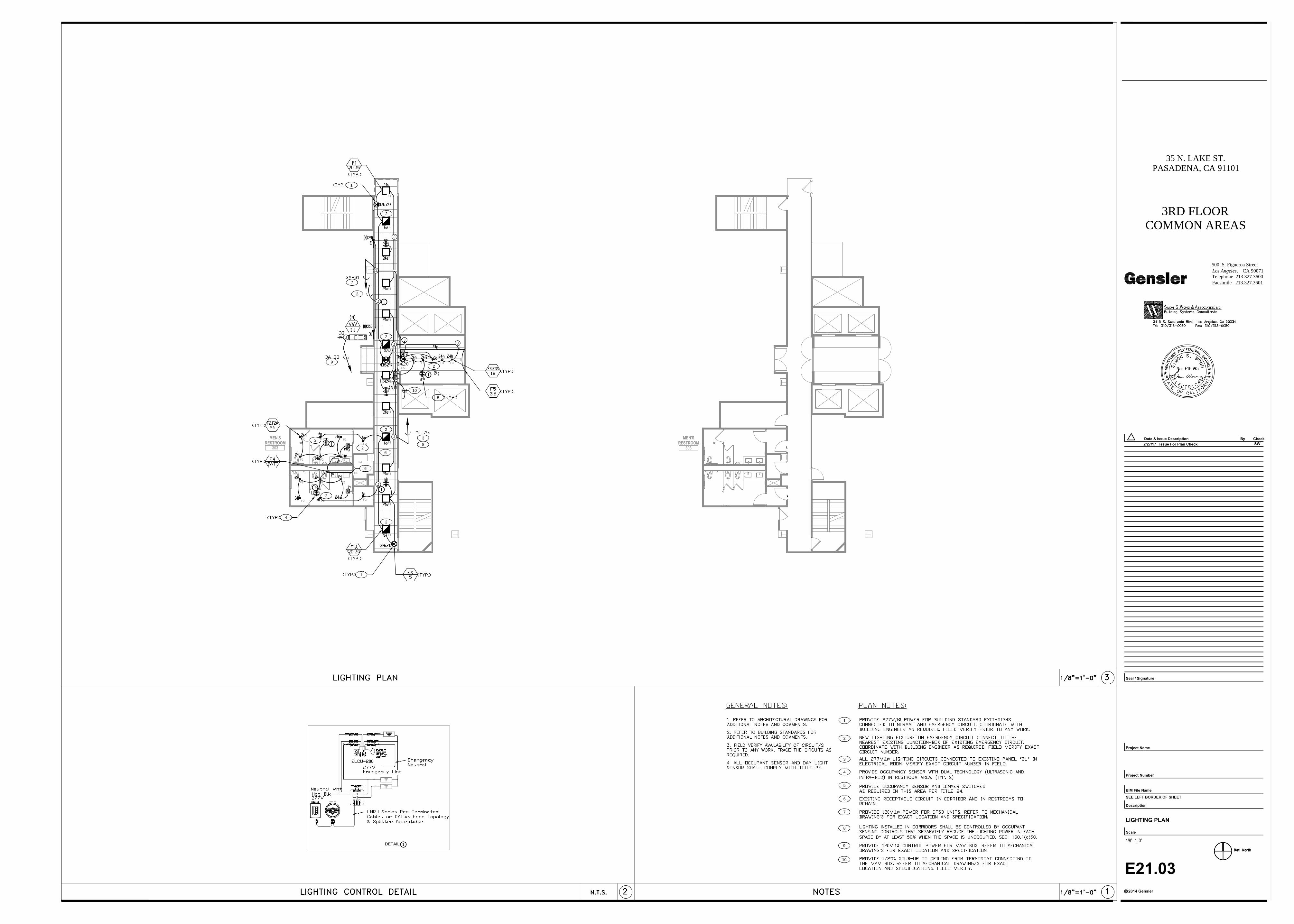
F2 F2
F2
F2
MEN'SRESTROOM
303
F1
F1
F1
F1
F1
F1
F1
F1
F1
F1
F1
F3 F3 F3 F3 F3
F2
F2 F2
F2 F2
F2 F2 F2
F2
F2
F5
F5
F4
F4
F1
MEN'SRESTROOM
303
5
3
2
1
4
Yel
Lighting
Load
(2)
Red
Lighting
Load
(1)
LMDC-100
DETAIL
6
7
3
J
J
J
J
J
4
1
1
2
2
2
2
2
2
2
J
6
6
5
J
J
7
2
8
8
2
9
9
10
10
E21.03
LIGHTING PLAN
CA 90071Los Angeles,
2014 Gensler
Project Number
BIM File Name
Scale
Description
c
Project Name
Seal / Signature
Check
Facsimile 213.327.3601Telephone 213.327.3600
Date & By
500 S. Figueroa Street
Issue Description
SEE LEFT BORDER OF SHEET
35 N. LAKE ST.PASADENA, CA 91101
3RD FLOORCOMMON AREAS
SW
Issue For Plan Check2/27/17
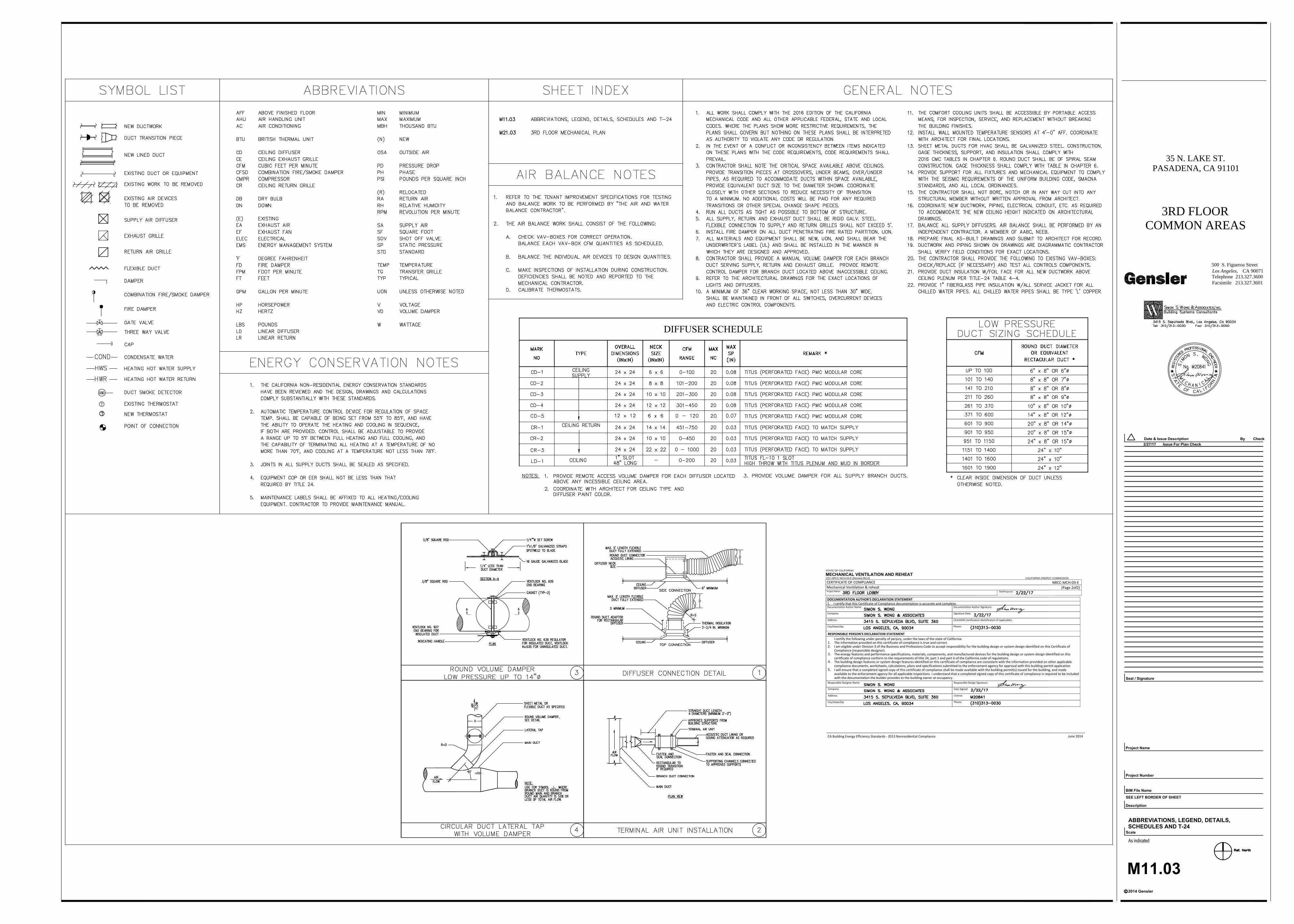
STATE OF CALIFORNIA
MECHANICAL VENTILATION AND REHEAT
CEC-NRCC-MCH-03-E (Revised 06/14) CALIFORNIA ENERGY COMMISSION
NRCC-MCH-03-E(Page 2of2)
DatePrepared:
DOCUMENTATION AUTHOR'S DECLARATION STATEMENT1. I certify that this Certificate of Compliance documentation is accurate and complete.Documentation Author Name: Documentation Author Signature:
Company: Signature Date:
Address: CEA/HERS Certification Identification (if applicable):
City/State/Zip: Phone:
RESPONSIBLE PERSON'S DECLARATION STATEMENTI certify the following under penalty of perjury, under the laws of the state of California:
1. The information provided on this certificate of compliance is true and correct.2. I am eligible under Division 3 of the Business and Professions Code to accept responsibility for the building design or system design identified on this Certificate of
Compliance (responsible designer).3. The energy features and performance specifications, materials, components, and manufactured devices for the building design or system design identified on this
certificate of compliance conform to the requirements of title 24, part 1 and part 6 of the California code of regulations.4. The building design features or system design features identified on this certificate of compliance are consistent with the information provided on other applicable
compliance documents, worksheets, calculations, plans and specifications submitted to the enforcement agency for approval with this building permit application5. I will ensure that a completed signed copy of this certificate of compliance shall be made available with the building permit(s) issued for the building, and made
available to the enforcement agency for all applicable inspections. I understand that a completed signed copy of this certificate of compliance is required to be includedwith the documentation the builder provides to the building owner at occupancy.
Responsible Designer Name: Responsible Design Signature:
Company: Date Signed:
Address: License:
City/State/Zip: Phone:
CA Building Energy Efficiency Standards - 2013 Nonresidential Compliance June 2014
CERTIFICATE OF COMPLIANCEMechanical Ventilation & reheatProject Name:
CA 90071Los Angeles,
2014 Gensler
Project Number
BIM File Name
Scale
Description
c
Project Name
Seal / Signature
Check
Facsimile 213.327.3601Telephone 213.327.3600
Date & By
500 S. Figueroa Street
Issue Description
SEE LEFT BORDER OF SHEET
35 N. LAKE ST.PASADENA, CA 91101
3RD FLOORCOMMON AREAS
Issue For Plan Check2/27/17
M11.03
ABBREVIATIONS, LEGEND, DETAILS,
SCHEDULES AND T-24
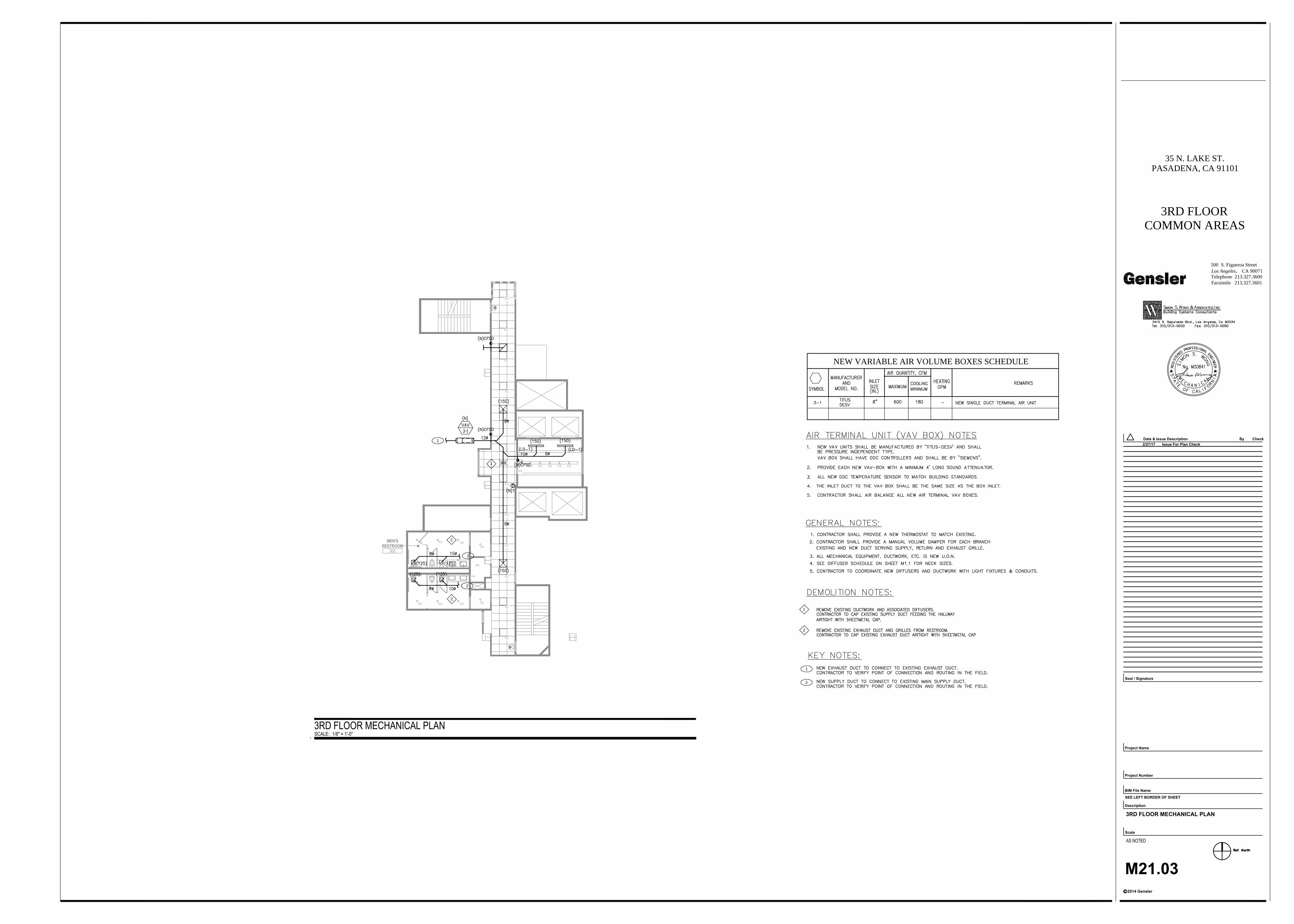
F2 F2
F2
F2
MEN'SRESTROOM
303
F1
F1
F1
F1
F1
F1
F1
F1
F1
F1
F1
F3 F3 F3 F3 F3
F2
F2 F2
F2 F2
F2 F2 F2
F2
F2
F5
F5
F4
F4
F1
1
2
2
1
2
2
1
2
1
2
NEW VARIABLE AIR VOLUME BOXES SCHEDULE
CA 90071Los Angeles,
2014 Gensler
Project Number
BIM File Name
Scale
Description
c
Project Name
Seal / Signature
Check
Facsimile 213.327.3601Telephone 213.327.3600
Date & By
500 S. Figueroa Street
Issue Description
SEE LEFT BORDER OF SHEET
35 N. LAKE ST.PASADENA, CA 91101
3RD FLOORCOMMON AREAS
Issue For Plan Check2/27/17
M21.03
3RD FLOOR MECHANICAL PLAN
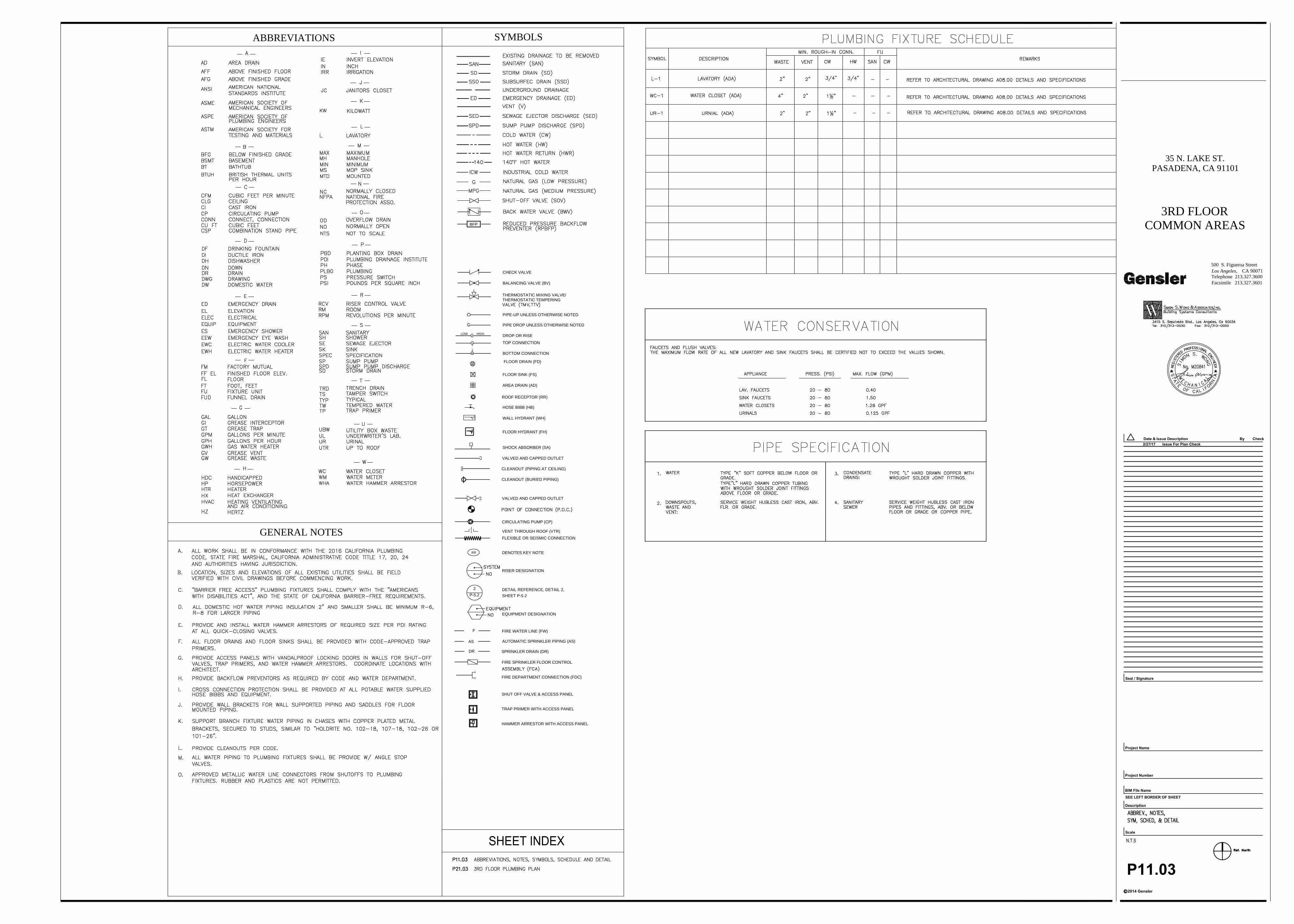
GENERAL NOTES
ABBREVIATIONS SYMBOLS
TRAP PRIMER WITH ACCESS PANEL
HAMMER ARRESTOR WITH ACCESS PANEL
SHUT OFF VALVE & ACCESS PANEL
RISER DESIGNATION
DENOTES KEY NOTE
SPRINKLER DRAIN (DR)
FIRE SPRINKLER FLOOR CONTROL
FIRE DEPARTMENT CONNECTION (FDC)
FIRE WATER LINE (FW)
AUTOMATIC SPRINKLER PIPING (AS)
EQUIPMENT DESIGNATION
DETAIL REFERENCE, DETAIL 2,
CIRCULATING PUMP (CP)
VENT THROUGH ROOF (VTR)
FLEXIBLE OR SEISMIC CONNECTION
VALVED AND CAPPED OUTLET
VALVED AND CAPPED OUTLET
CLEANOUT (BURIED PIPING)
CLEANOUT (PIPING AT CEILING)
SHOCK ABSORBER (SA)
FLOOR HYDRANT (FH)
##
DR
AS
F
SHEET P-5.2
2
P-5.2
ROOF RECEPTOR (RR)
WALL HYDRANT (WH)
BOTTOM CONNECTION
PIPE-UP UNLESS OTHERWISE NOTED
PIPE DROP UNLESS OTHERWISE NOTED
THERMOSTATIC TEMPERING
BALANCING VALVE (BV)
THERMOSTATIC MIXING VALVE/
LOW
HOSE BIBB (HB)
FLOOR SINK (FS)
AREA DRAIN (AD)
DROP OR RISE
FLOOR DRAIN (FD)
TOP CONNECTION
HIGH
CHECK VALVE
BFP
CA 90071Los Angeles,
2014 Gensler
Project Number
BIM File Name
Scale
Description
c
Project Name
Seal / Signature
Check
Facsimile 213.327.3601Telephone 213.327.3600
Date & By
500 S. Figueroa Street
Issue Description
SEE LEFT BORDER OF SHEET
35 N. LAKE ST.PASADENA, CA 91101
3RD FLOORCOMMON AREAS
Issue For Plan Check2/27/17
P11.03
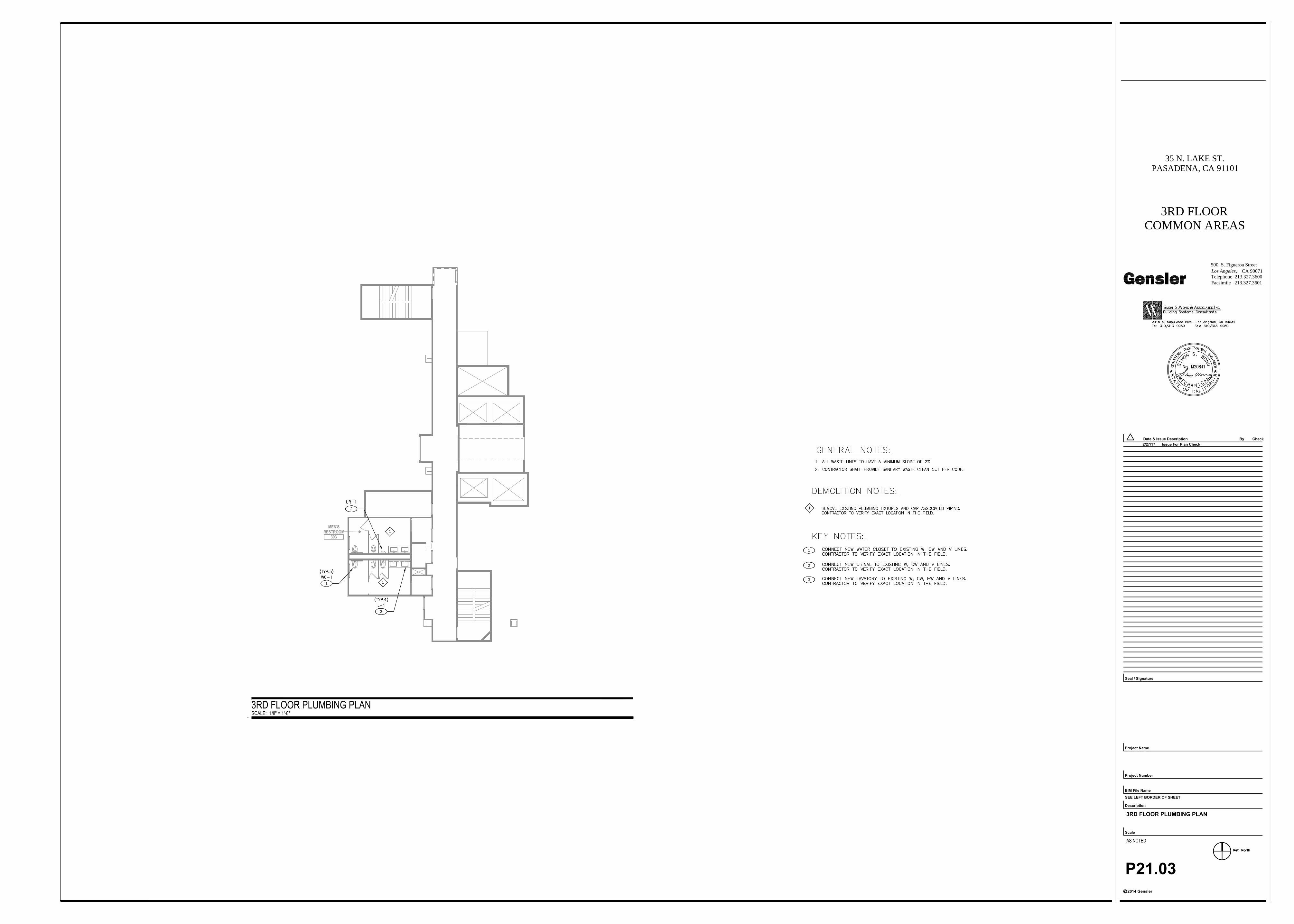
MEN'SRESTROOM
3031
1
2
3
1
1
1
2
3
CA 90071Los Angeles,
2014 Gensler
Project Number
BIM File Name
Scale
Description
c
Project Name
Seal / Signature
Check
Facsimile 213.327.3601Telephone 213.327.3600
Date & By
500 S. Figueroa Street
Issue Description
SEE LEFT BORDER OF SHEET
35 N. LAKE ST.PASADENA, CA 91101
3RD FLOORCOMMON AREAS
Issue For Plan Check2/27/17
P21.03
3RD FLOOR PLUMBING PLAN