Embed Size (px)
Citation preview
500kW Power ModuleSite Preparation and Installation
Power Module Site Preparation and Installation Guide
Schneider Electric Site Preparation and Installation
Page 2 CONTROLLED DISTRIBUTION © 2013 Schneider Electric. All rights reserved.
Safety information
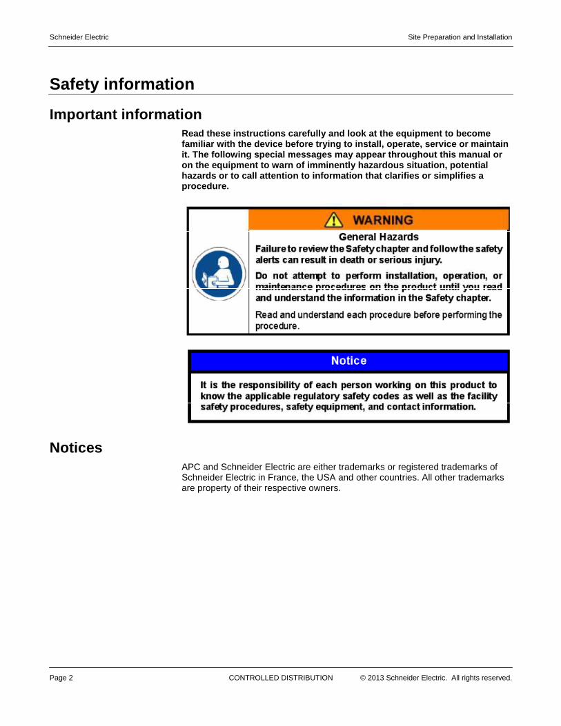
Important information Read these instructions carefully and look at the e quipment to become familiar with the device before trying to install, operate, service or maintain it. The following special messages may appear throu ghout this manual or on the equipment to warn of imminently hazardous si tuation, potential hazards or to call attention to information that cl arifies or simplifies a procedure.
Notices APC and Schneider Electric are either trademarks or registered trademarks of Schneider Electric in France, the USA and other countries. All other trademarks are property of their respective owners.
Site Preparation and Installation Schneider Electric
© 2013 Schneider Electric. All rights reserved. CONTROLLED DISTRIBUTION Page 3
Explanation of Hazard Alerts This manual and this product use industry standard of hazard alerts to notify the user about personal or equipment safety hazards. Human Safety alerts contain three elements:
• Signal Word and Color • Safety Text • Safety Icon (s)
Signal Words Signal words inform personnel of the level of hazard. Refer to the definitions that follow:
Signal Word Definitions
DANGER Indicates a hazardous situation, which, if not avoided, will result in death or serious injury.. This signal word is to be limited to the most extreme situations.
WARNING Indicates a hazardous situation, which, if not avoided, could result in death or serious injury.
CAUTION Indicates a hazardoud situation, which, if not avoided, may result in minor or moderate injury.
NOTICE Indicates a situation, which, if not avoided, could result in property damage.
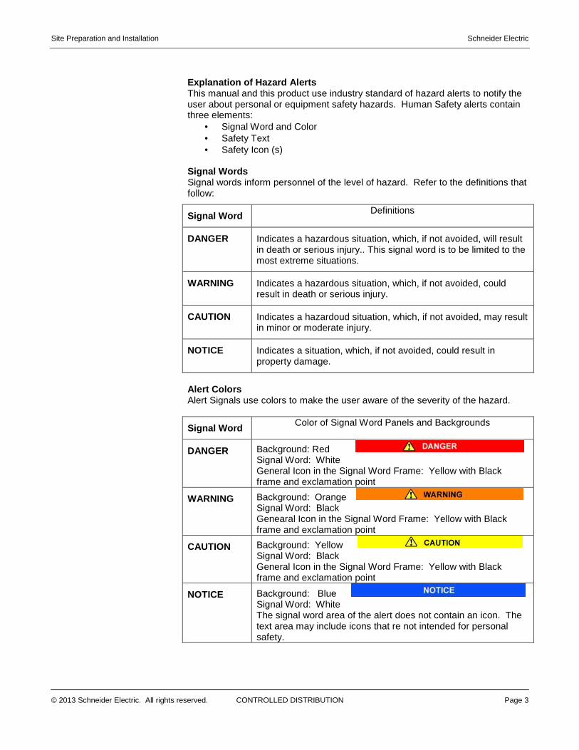
Alert Colors Alert Signals use colors to make the user aware of the severity of the hazard.
Signal Word Color of Signal Word Panels and Backgrounds
DANGER Background: Red Signal Word: White General Icon in the Signal Word Frame: Yellow with Black frame and exclamation point
WARNING Background: Orange Signal Word: Black Genearal Icon in the Signal Word Frame: Yellow with Black frame and exclamation point
CAUTION Background: Yellow Signal Word: Black General Icon in the Signal Word Frame: Yellow with Black frame and exclamation point
NOTICE Background: Blue Signal Word: White The signal word area of the alert does not contain an icon. The text area may include icons that re not intended for personal safety.
Schneider Electric Site Preparation and Installation
Page 4 CONTROLLED DISTRIBUTION © 2013 Schneider Electric. All rights reserved.
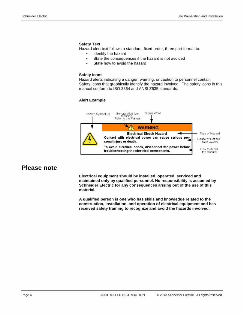
Safety Text Hazard alert text follows a standard, fixed-order, three part format to:
• Identify the hazard • State the consequences if the hazard is not avoided • State how to avoid the hazard
Safety Icons Hazard alerts indicating a danger, warning, or caution to personnel contain Safety Icons that graphically identify the hazard involved. The safety icons in this manual conform to ISO 3864 and ANSI Z535 standards.
Alert Example
Please note
Electrical equipment should be installed, operated, serviced and maintained only by qualified personnel. No responsi bility is assumed by Schneider Electric for any consequences arising out of the use of this material.
A qualified person is one who has skills and knowle dge related to the construction, installation, and operation of electr ical equipment and has received safety training to recognize and avoid the hazards involved.
Site Preparation and Installation Schneider Electric
© 2013 Schneider Electric. All rights reserved. CONTROLLED DISTRIBUTION Page 5
Table of Contents Safety information .............................................................................................2
Important information .................................................................................................. 2
Notices ..............................................................................................................2
Table of Contents ................................. ................................................................5
1. Safety Information ............................. ...............................................................7
2. Transportation, Lifting and Installation........ ..................................................9
2.1 Transportation Considerations ................................................................. 10
2.2 Load Distribution ...................................................................................... 10
2.3 Local and National Codes ........................................................................ 10
2.4 Overall Dimension and Weight ................................................................. 11
2.5 Lifting ........................................................................................................ 11
2.6 Stackability ............................................................................................... 12
2.7 Leveling .................................................................................................... 12
2.8 Positioning and Orientation ...................................................................... 12
2.9 Pad or Mounting Design ........................................................................... 13
2.10 Disclaimer ............................................................................................... 14
3. Site Requirements – Conditions ................. ................................................. 15
3.1 Zoning Regulations and Permitting Considerations ................................. 15
3.2 Wind Loading Capacity ............................................................................ 15
3.3 Weight Bearing Requirements ................................................................. 15
3.4 Uplift/Lateral Capacity of Foundation ....................................................... 16
3.5 Surface Requirements ............................................................................. 16
3.6 Water Drainage Requirements ................................................................. 16
3.7 Clearance Requirements ......................................................................... 16
3.7a Minimum Clearances Around Module: .............................................................. 16
3.8 Ingress/Egress Requirements .................................................................. 17
3.9 Environmental Considerations ................................................................. 17
3.10 Operating Specifications ........................................................................ 17
4. Base Anchors and Fixtures ...................... .................................................... 18
4.1 Hold-Down Fixtures for Single (non-stacked) Configuration .................... 18
5. Electrical Utility Connections ................. ...................................................... 20
5.1 Electrical Grounding & Lightning Protection ............................................ 20
5.2 Electrical Utility Connections .................................................................... 20
5.2a Electrical Requirements: ................................................................................... 21

Schneider Electric Site Preparation and Installation
Page 6 CONTROLLED DISTRIBUTION © 2013 Schneider Electric. All rights reserved.
5.3 Above Ground/Overhead Cable Installation ............................................ 22
5.4 Switchboard and Generator Wiring .......................................................... 22
6. Additional Considerations ...................... ...................................................... 25
6.1 Severe Weather Conditions and Natural Disasters ................................. 25
6.2 Physical Threat and Security ................................................................... 25
Site Preparation and Installation Schneider Electric
© 2013 Schneider Electric. All rights reserved. CONTROLLED DISTRIBUTION Page 7
1. Safety Information � All electrical changes and maintenance to and within the product must be
performed by a licensed electrician.
� All refrigerant system changes and maintenance to and within the product must be performed by a certified HVAC engineer that is approved to work with refrigerant systems (F-Gas Regulations) and on refrigerant lines.
� Refer to general safety instructions for each component inside the product.
� The product is not intended for human occupancy other than short duration access to carry out essential maintenance
� No user serviceable parts are behind panels that require tools to open.
� Consult your local planning office for applicable codes and to review necessary permitting guidelines for your specific site.
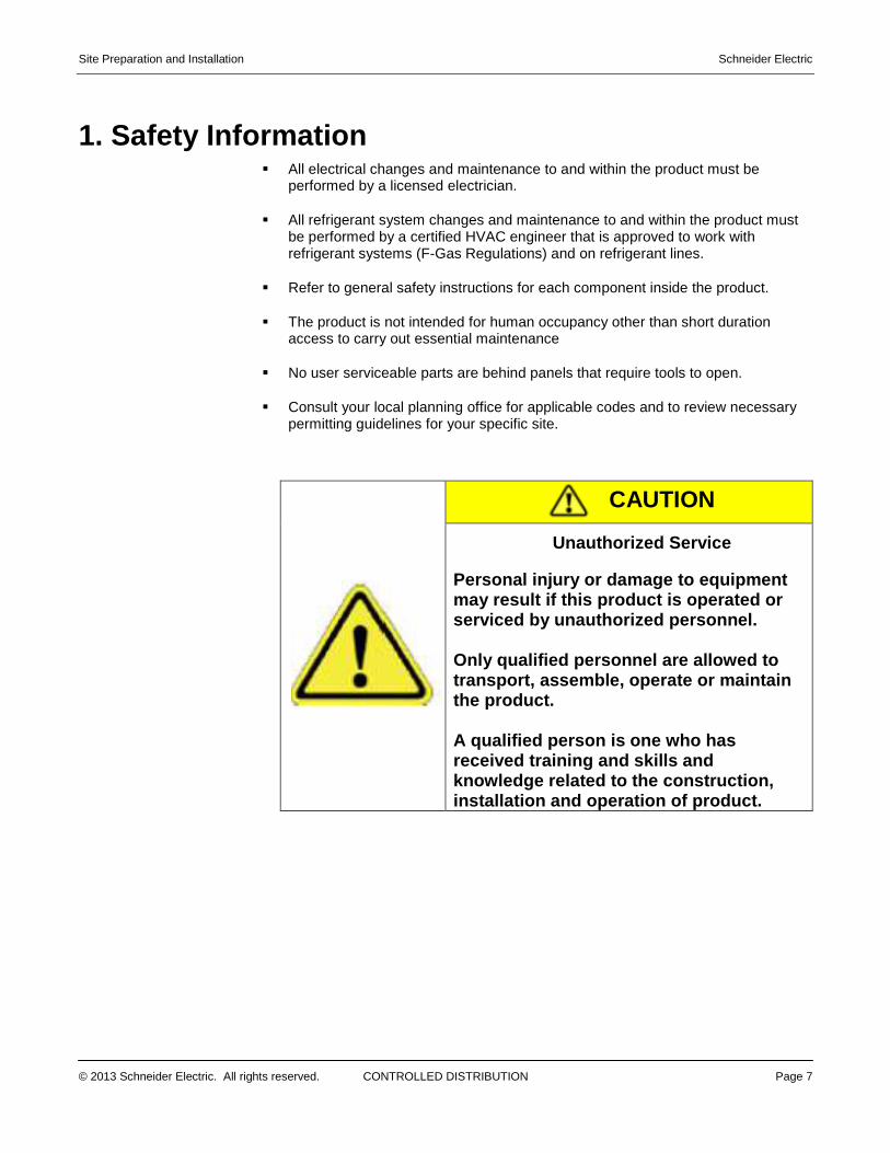
CAUTION
Unauthorized Service
Personal injury or damage to equipment may result if this product is operated or serviced by unauthorized personnel. Only qualified personnel are allowed to transport, assemble, operate or maintain the product. A qualified person is one who has received training and skills and knowledge related to the construction, installation and operation of product.
Schneider Electric Site Preparation and Installation
Page 8 CONTROLLED DISTRIBUTION © 2013 Schneider Electric. All rights reserved.
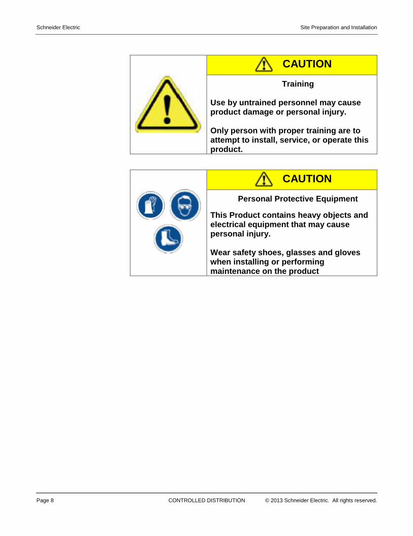
CAUTION
Training
Use by untrained personnel may cause product damage or personal injury. Only person with proper training are to attempt to install, service, or operate this product.
CAUTION
Personal Protective Equipment
This Product contains heavy objects and electrical equipment that may cause personal injury. Wear safety shoes, glasses and gloves when installing or performing maintenance on the product
Site Preparation and Installation Schneider Electric
© 2013 Schneider Electric. All rights reserved. CONTROLLED DISTRIBUTION Page 9
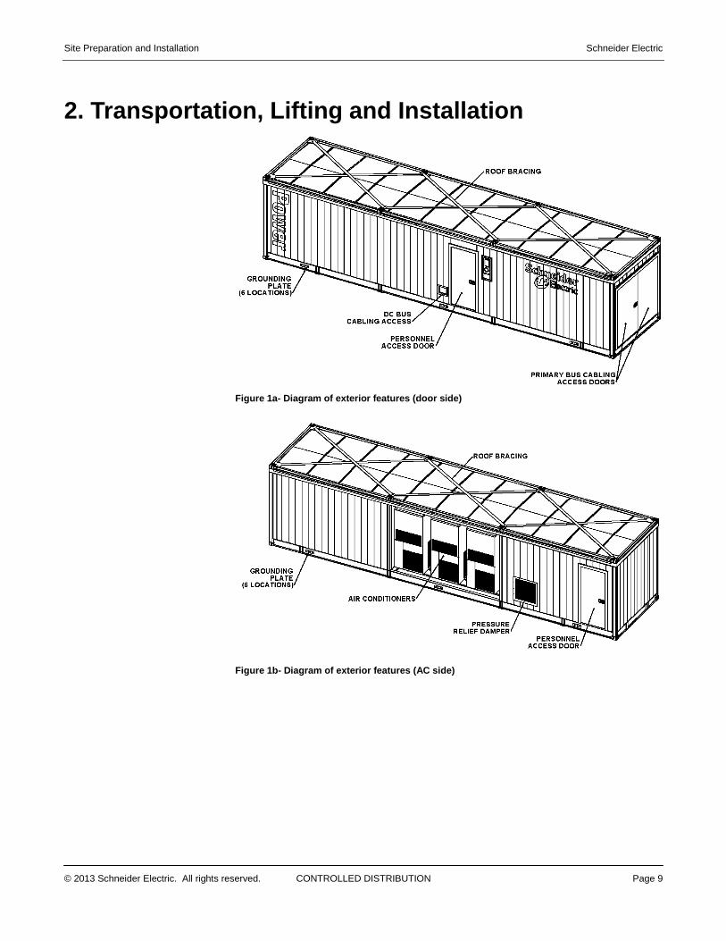
2. Transportation, Lifting and Installation
Figure 1a- Diagram of exterior features (door side)
Figure 1b- Diagram of exterior features (AC side)
Schneider Electric Site Preparation and Installation
Page 10 CONTROLLED DISTRIBUTION © 2013 Schneider Electric. All rights reserved.
2.1 Transportation Considerations Contact Schneider Electric for guidance before moving or decommissioning the Power Module. Be sure the following conditions are satisfied: � All input and output power lines are disconnected.
� UPS batteries are removed from the large UPS
� Small UPS inside of the primary switchboard is turned off.
� Any loose items are tied down or removed.
� Outside ground connections are removed.
� Outside tie-downs are removed.
� All doors are secured.
� No other outside attachments remain such as security cameras etc.
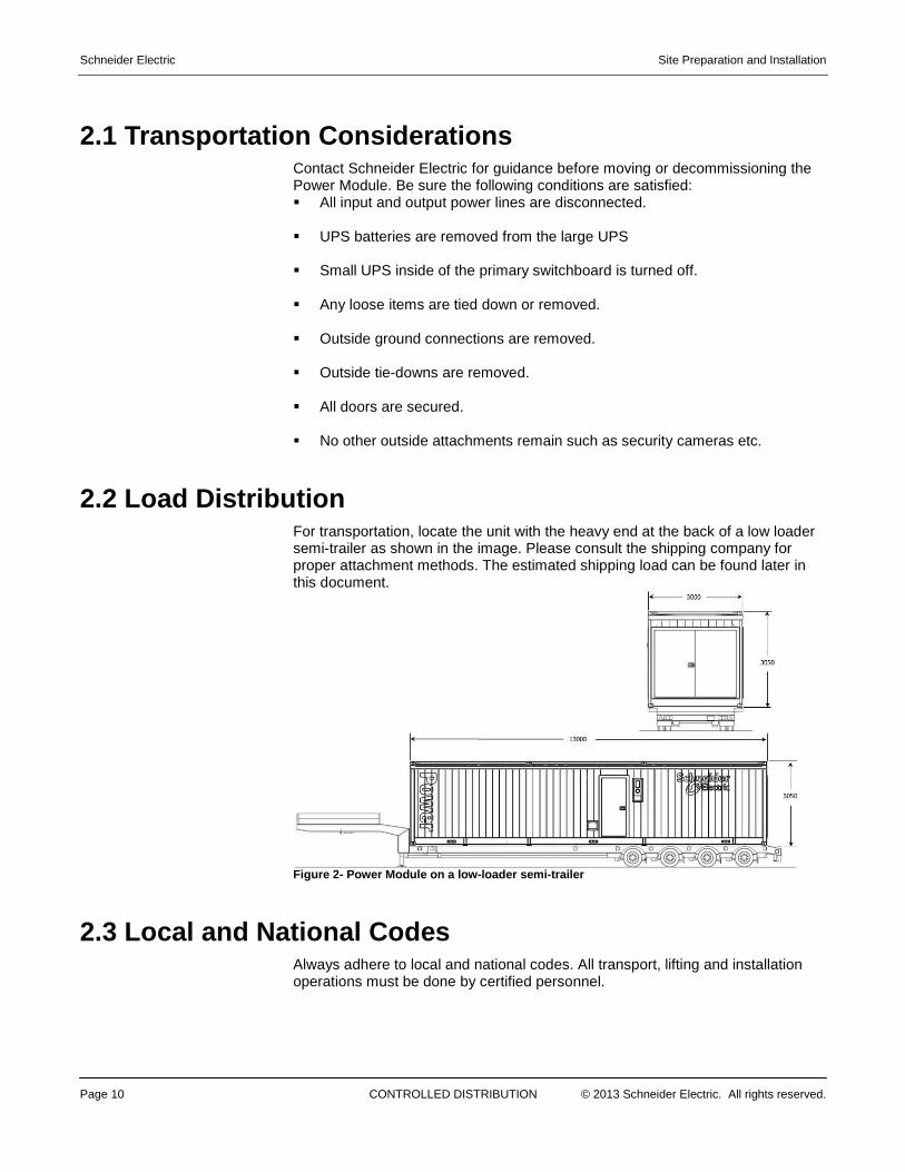
2.2 Load Distribution For transportation, locate the unit with the heavy end at the back of a low loader semi-trailer as shown in the image. Please consult the shipping company for proper attachment methods. The estimated shipping load can be found later in this document.
Figure 2- Power Module on a low-loader semi-trailer
2.3 Local and National Codes Always adhere to local and national codes. All transport, lifting and installation operations must be done by certified personnel.
Site Preparation and Installation Schneider Electric
© 2013 Schneider Electric. All rights reserved. CONTROLLED DISTRIBUTION Page 11
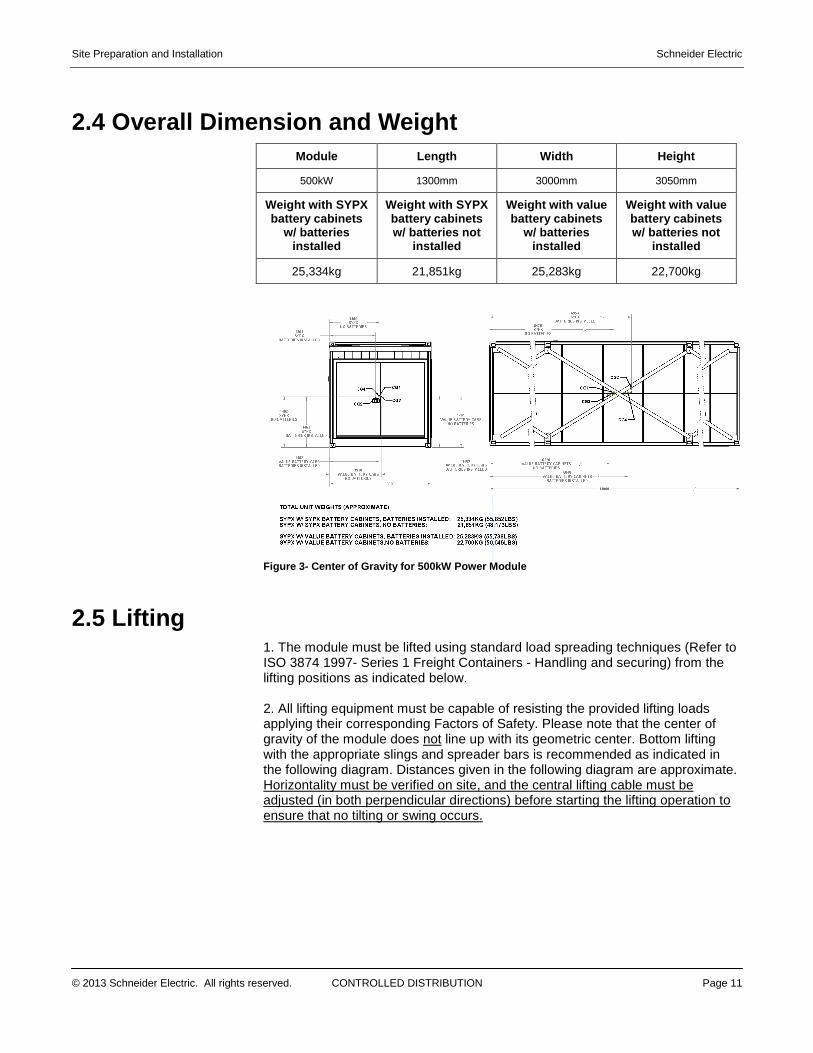
2.4 Overall Dimension and Weight Module Length Width Height
500kW 1300mm 3000mm 3050mm
Weight with SYPX battery cabinets
w/ batteries installed
Weight with SYPX battery cabinets w/ batteries not
installed
Weight with value battery cabinets
w/ batteries installed
Weight with value battery cabinets w/ batteries not
installed
25,334kg 21,851kg 25,283kg 22,700kg
Figure 3- Center of Gravity for 500kW Power Module
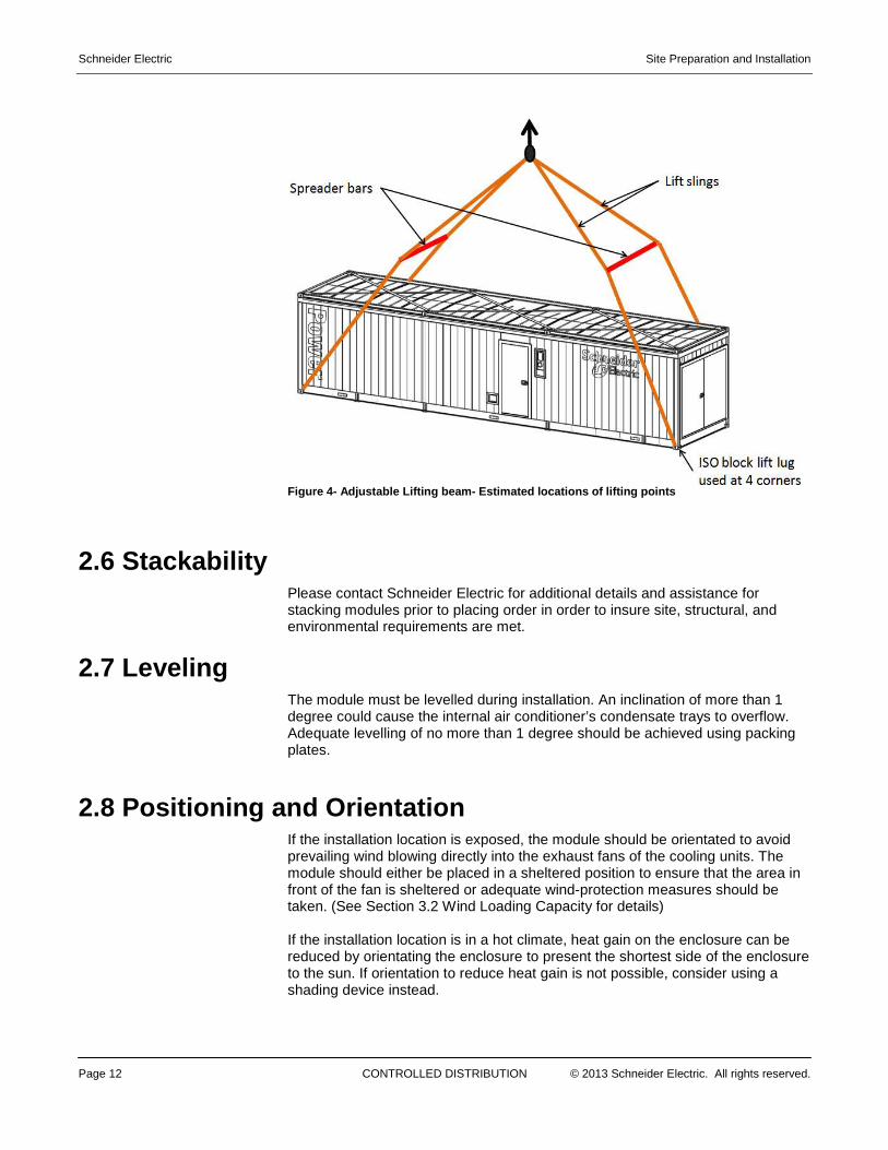
2.5 Lifting 1. The module must be lifted using standard load spreading techniques (Refer to ISO 3874 1997- Series 1 Freight Containers - Handling and securing) from the lifting positions as indicated below. 2. All lifting equipment must be capable of resisting the provided lifting loads applying their corresponding Factors of Safety. Please note that the center of gravity of the module does not line up with its geometric center. Bottom lifting with the appropriate slings and spreader bars is recommended as indicated in the following diagram. Distances given in the following diagram are approximate. Horizontality must be verified on site, and the central lifting cable must be adjusted (in both perpendicular directions) before starting the lifting operation to ensure that no tilting or swing occurs.
Schneider Electric Site Preparation and Installation
Page 12 CONTROLLED DISTRIBUTION © 2013 Schneider Electric. All rights reserved.
Figure 4- Adjustable Lifting beam- Estimated locati ons of lifting points
2.6 Stackability
Please contact Schneider Electric for additional details and assistance for stacking modules prior to placing order in order to insure site, structural, and environmental requirements are met.
2.7 Leveling The module must be levelled during installation. An inclination of more than 1 degree could cause the internal air conditioner’s condensate trays to overflow. Adequate levelling of no more than 1 degree should be achieved using packing plates.
2.8 Positioning and Orientation If the installation location is exposed, the module should be orientated to avoid prevailing wind blowing directly into the exhaust fans of the cooling units. The module should either be placed in a sheltered position to ensure that the area in front of the fan is sheltered or adequate wind-protection measures should be taken. (See Section 3.2 Wind Loading Capacity for details) If the installation location is in a hot climate, heat gain on the enclosure can be reduced by orientating the enclosure to present the shortest side of the enclosure to the sun. If orientation to reduce heat gain is not possible, consider using a shading device instead.

Site Preparation and Installation Schneider Electric
© 2013 Schneider Electric. All rights reserved. CONTROLLED DISTRIBUTION Page 13
In addition, the area should be free from obstruction to allow for large trailers to access to the site and for a crane to lift the module and place it on its support pad. Consideration should be given to obstructions such as adjacent buildings, trees, lamp posts, low and high voltage wires, etc., The module must not be located within 200m of the sea. For marine applications, contact Schneider Electric for additional details. Note : Insure that considerations are made in regards to the proximity and access to utility and/or generator power, drainage, network connections, water or chilled water, if applicable.
2.9 Pad or Mounting Design
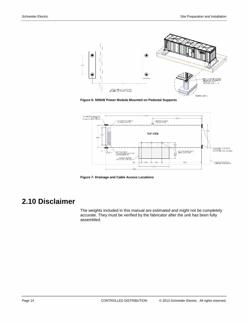
When planning to install your module on a concrete pad or pedestal supports (See Figure 5 and 6, respectively), in addition to adhering to the above specifications discussed in this document, it is advisable to work with a qualified general contractor and civil engineering firm to ensure proper design and construction of your mounting pad. As mentioned above, consideration should be given to location, extreme weather conditions, proximity to site resources, delivery, installation of the module or multiple modules, access to modules by personnel and equipment, and clearance around air conditioners and vents. Place module in a location that allows for water to drain away from the module (See Figure 7). Insure that your pad has the means to anchor the module and complies with local seismic requirements. The pad design must be able to support the weight of a fully loaded module. Accessibility of staff and contractors should also be considered and may include the need for steps or ramps to meet local and national codes. In addition to anchoring, the pad can also be used to run the cables under the product. Figure 7 shows where the electrical conduit and networking cables should emerge from the pad. Local regulations should be followed when designing the conduit in the pad.
Figure 5- 500kW Power Module mounted on pad
Schneider Electric Site Preparation and Installation
Page 14 CONTROLLED DISTRIBUTION © 2013 Schneider Electric. All rights reserved.
Figure 6- 500kW Power Module Mounted on Pedestal Su pports
Figure 7- Drainage and Cable Access Locations
2.10 Disclaimer The weights included in this manual are estimated and might not be completely accurate. They must be verified by the fabricator after the unit has been fully assembled.
Site Preparation and Installation Schneider Electric
© 2013 Schneider Electric. All rights reserved. CONTROLLED DISTRIBUTION Page 15
3. Site Requirements – Conditions
3.1 Zoning Regulations and Permitting Consideration s Prior to the installation of the module, it is important to determine any applicable specific zoning regulations or permitting requirements. Engaging with the Authority Having Jurisdiction (AHJ) early on in the site planning process along with the property owner, if applicable, will allow for a trouble-free installation of the module. It is the customer’s responsibility to determine, comprehend and adhere to all local and national code and regulations as they pertain to their specific site, the installation of the module, and the electrical power connections.
3.2 Wind Loading Capacity The product can be used in a wide range of locations according to the following maximum condition Wind: Very High. Maximum basic Speed of 68m/s (150mph) The foundation loads included in this report correspond to the critical combination of actions for the largest wind demand.
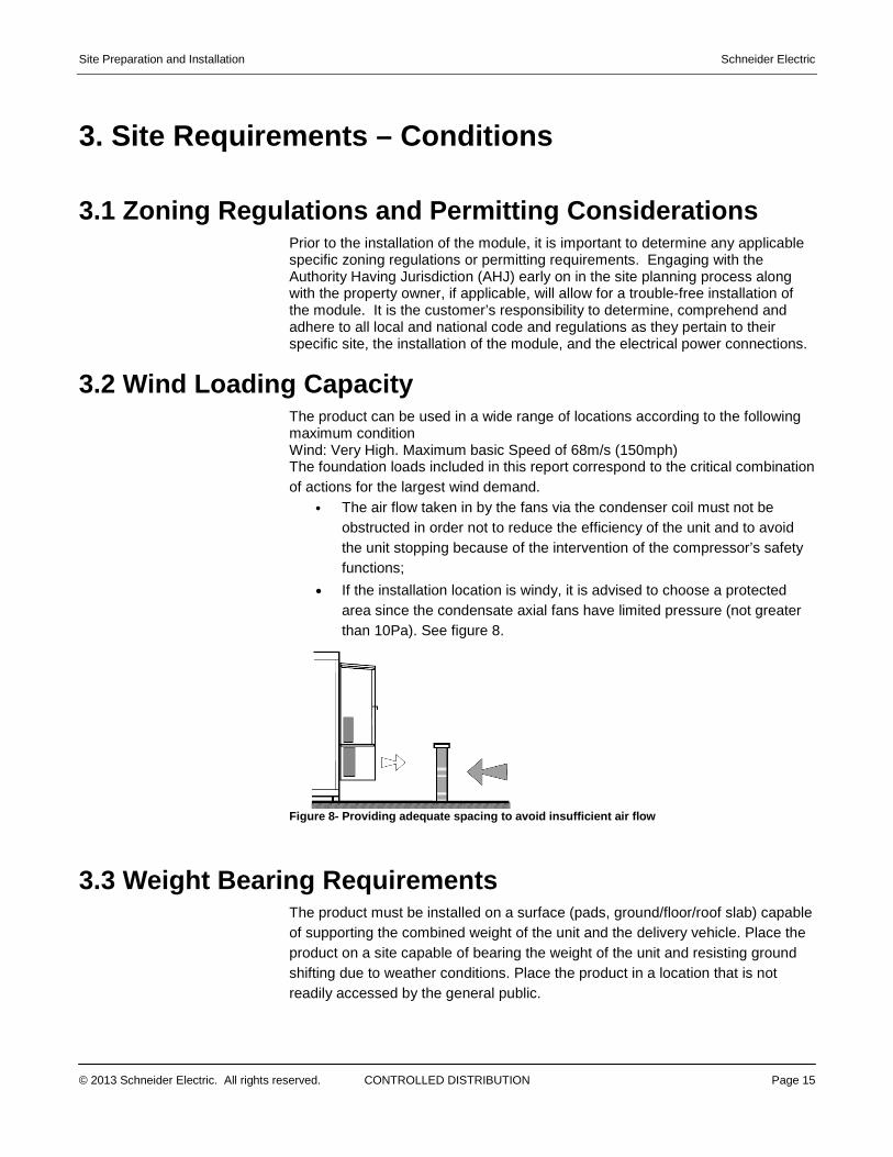
• The air flow taken in by the fans via the condenser coil must not be obstructed in order not to reduce the efficiency of the unit and to avoid the unit stopping because of the intervention of the compressor’s safety functions;
• If the installation location is windy, it is advised to choose a protected area since the condensate axial fans have limited pressure (not greater than 10Pa). See figure 8.
Figure 8- Providing adequate spacing to avoid insuf ficient air flow
3.3 Weight Bearing Requirements The product must be installed on a surface (pads, ground/floor/roof slab) capable of supporting the combined weight of the unit and the delivery vehicle. Place the product on a site capable of bearing the weight of the unit and resisting ground shifting due to weather conditions. Place the product in a location that is not readily accessed by the general public.
Schneider Electric Site Preparation and Installation
Page 16 CONTROLLED DISTRIBUTION © 2013 Schneider Electric. All rights reserved.
3.4 Uplift/Lateral Capacity of Foundation Due to high wind loads and seismic demand, the unit must be anchored down to the base at the indicated positions using adequate brackets or fixings. See section four for additional details on anchorage
3.5 Surface Requirements The product can be installed on adequately designed concrete pad or pads suitable for its dimensions, weight and base loads, or the finished floor of a building. Before installing, ensure the stability of the surface or the structure where the unit will be placed is maintained. Take care to make sure these adequate conditions remain constant over the expected lifetime of the module installation. All the bases must have adequate vertical support, and all ISO-block bases must be fastened down to the foundation (support structure) by adequate brackets or fixings. The end user must ensure that the supporting ground conditions are adequate. Foundation design should be completed by a local contractor. See additional consideration around pad design in Section 6.0.
3.6 Water Drainage Requirements For external installations, care must be taken to place the product in a location that is graded to drain water away from the module. Ground pads/slabs should be raised up above the surrounding ground surface level to prevent water ingress (min 150mm).
3.7 Clearance Requirements Proper clearances must be observed for all of the travel routes to and on the customer property. If a crane is used to place the container, the greater of the clearances required by the crane or tractor trailer needs to be considered and the area above and around the crane must be free of obstructions: overhead power lines, etc.
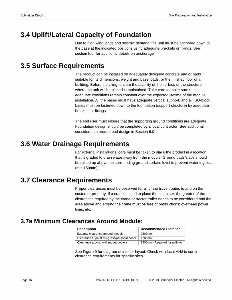
3.7a Minimum Clearances Around Module: Description Recommended Distance External clearance around module 2500mm Clearance at point of egress/personal doors 1200mm Clearance around wall mount coolers 1500mm (Required for airflow)
See Figure 9 for diagram of interior layout. Check with local AHJ to confirm clearance requirements for specific sites.
Site Preparation and Installation Schneider Electric
© 2013 Schneider Electric. All rights reserved. CONTROLLED DISTRIBUTION Page 17
Figure 9- Diagram of interior layout
3.8 Ingress/Egress Requirements Door Dimension (W X H)
Main Access Door 1000mm X 2100mm
3.9 Environmental Considerations Schneider Electric prefabricated enclosures are designed and manufactured to be installed in harsh environmental conditions. The module enclosure is designed and manufactured to protect the electrical equipment within from adverse weather conditions. Customers should never operate the module with the access doors open in order to avoid excess wind-driven dust and debris. Batteries should not be stored in high temperatures above 30° C for prolonged periods of time. Doing so will impact the overall health of the batteries.
3.10 Operating Specifications Condition Range
Ambient Temperature- min/max -20° C to 50° C
Internal Temperature 10° C to 35° C (Batteries shou ld be kept at 25° C)
Humidity – External / Humidity - Internal 0-100% / 20 to 80%
Altitude 0 – 1000m; above 1000m require derating of system
Audible Noise (pressure) <45 dB (A) @10m
Schneider Electric Site Preparation and Installation
Page 18 CONTROLLED DISTRIBUTION © 2013 Schneider Electric. All rights reserved.
4. Base Anchors and Fixtures
4.1 Hold-Down Fixtures for Single (non-stacked) Configuration
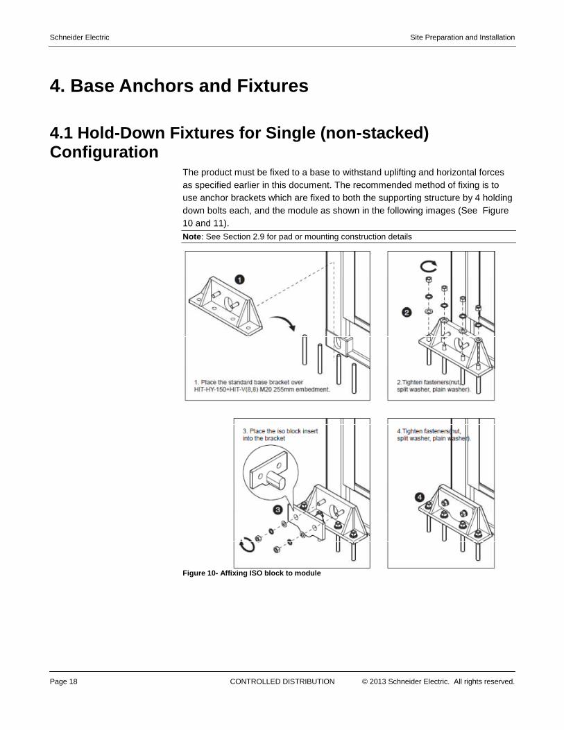
The product must be fixed to a base to withstand uplifting and horizontal forces as specified earlier in this document. The recommended method of fixing is to use anchor brackets which are fixed to both the supporting structure by 4 holding down bolts each, and the module as shown in the following images (See Figure 10 and 11). Note : See Section 2.9 for pad or mounting construction details
Figure 10- Affixing ISO block to module
Site Preparation and Installation Schneider Electric
© 2013 Schneider Electric. All rights reserved. CONTROLLED DISTRIBUTION Page 19
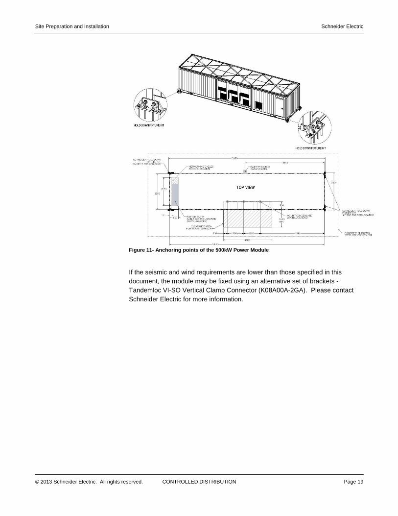
Figure 11- Anchoring points of the 500kW Power Modu le
If the seismic and wind requirements are lower than those specified in this document, the module may be fixed using an alternative set of brackets - Tandemloc VI-SO Vertical Clamp Connector (K08A00A-2GA). Please contact Schneider Electric for more information.
Schneider Electric Site Preparation and Installation
Page 20 CONTROLLED DISTRIBUTION © 2013 Schneider Electric. All rights reserved.
5. Electrical Utility Connections
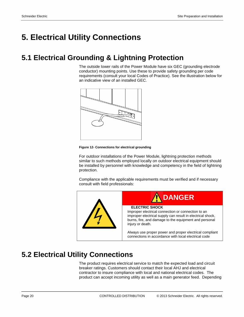
5.1 Electrical Grounding & Lightning Protection The outside lower rails of the Power Module have six GEC (grounding electrode conductor) mounting points. Use these to provide safety grounding per code requirements (consult your local Codes of Practice). See the illustration below for an indicative view of an installed GEC.
Figure 12- Connections for electrical grounding
For outdoor installations of the Power Module, lightning protection methods similar to such methods employed locally on outdoor electrical equipment should be installed by personnel with knowledge and competency in the field of lightning protection. Compliance with the applicable requirements must be verified and if necessary consult with field professionals:
DANGER
ELECTRIC SHOCK Improper electrical connection or connection to an improper electrical supply can result in electrical shock, burns, fire, and damage to the equipment and personal injury or death. Always use proper power and proper electrical compliant connections in accordance with local electrical code
5.2 Electrical Utility Connections The product requires electrical service to match the expected load and circuit breaker ratings. Customers should contact their local AHJ and electrical contractor to insure compliance with local and national electrical codes. The product can accept incoming utility as well as a main generator feed. Depending
Site Preparation and Installation Schneider Electric
© 2013 Schneider Electric. All rights reserved. CONTROLLED DISTRIBUTION Page 21
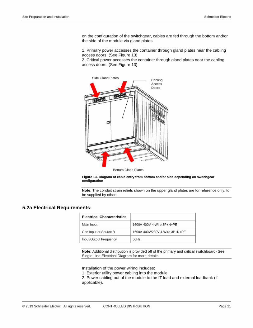
on the configuration of the switchgear, cables are fed through the bottom and/or the side of the module via gland plates. 1. Primary power accesses the container through gland plates near the cabling access doors. (See Figure 13) 2. Critical power accesses the container through gland plates near the cabling access doors. (See Figure 13)
Figure 13- Diagram of cable entry from bottom and/o r side depending on switchgear configuration
Note : The conduit strain reliefs shown on the upper gland plates are for reference only, to be supplied by others.
5.2a Electrical Requirements:
Electrical Characteristics
Main Input 1600A 400V 4-Wire 3P+N+PE
Gen Input or Source B 1600A 400V/230V 4-Wire 3P+N+PE
Input/Output Frequency 50Hz
Note : Additional distribution is provided off of the primary and critical switchboard- See Single Line Electrical Diagram for more details
Installation of the power wiring includes: 1. Exterior utility power cabling into the module 2. Power cabling out of the module to the IT load and external loadbank (if applicable).
Side Gland Plates
Bottom Gland Plates
Cabling Access Doors
Schneider Electric
Page 22
3. Power cabling and/or bus duct between the power module and the mechanical plant Note : Customers are responsible for determining the power wiring requirements for any chiller system. Contact Schneider Electric for guidance.
5.3 Above Ground/Overhead Cable Installation
For above ground cables use overhead cable ladders, conduit, or equivaleraised conductor means to route exterior wires to the Power Module. Ensure that all external wire entrances through the gland plates are sealed weather tight. Follow local and national codes.� Supply the module from a grounded 4� The min
aluminum� Size all conductors following local and national codes
5.4 Switchboard and Generator WiringThe primary bus switchboard is located along one module
Site Preparation and Installation
CONTROLLED DISTRIBUTION © 2013 Schneider Electric. All rights reserved.
3. Power cabling and/or bus duct between the power module and the mechanical
Customers are responsible for determining the power wiring requirements for any chiller system. Contact Schneider Electric for guidance.
Above Ground/Overhead Cable Installation For above ground cables use overhead cable ladders, conduit, or equivaleraised conductor means to route exterior wires to the Power Module. Ensure that all external wire entrances through the gland plates are sealed weather tight. Follow local and national codes.
Supply the module from a grounded 4-wire WYE service.The minimum temperature rating of conductors is 75 deg C. Use copper or aluminum conductors. Size all conductors following local and national codes
Switchboard and Generator Wiring The primary bus switchboard is located along one of the long sides of the module. The Bypass Input breaker switchboard on the right is optional.
WARNING
ELECTRIC SHOCK, EXPLOSION OR ARC FLASH HAZARD
Do not drill, cut or file metal over the top of switchboards. Failure to follow this can cause serious personal injury or death and equipment damage.
Site Preparation and Installation
Schneider Electric. All rights reserved.
3. Power cabling and/or bus duct between the power module and the mechanical
Customers are responsible for determining the power wiring requirements for any
For above ground cables use overhead cable ladders, conduit, or equivalent raised conductor means to route exterior wires to the Power Module. Ensure that all external wire entrances through the gland plates are sealed weather tight.
wire WYE service. imum temperature rating of conductors is 75 deg C. Use copper or
of the long sides of the Bypass Input breaker switchboard on the right is optional.
WARNING
ELECTRIC SHOCK, EXPLOSION OR
Do not drill, cut or file metal over the top
can cause serious personal injury or death and equipment
Site Preparation and Installation
© 2013 Schneider Electric. All rights reserved.
For circuit breaker wiring, refer to Schneider Electric Installation manuals for your specific switchgear and circuit breaker type.
CONTROLLED DISTRIBUTION
WARNING
ELECTRIC SHOCK AND FIRE HAZARD
All field electrical work must be performed by licensed electrician. All wiring must comply with all national and/or local electrical codes Failure to comply this can cause overloading of wiring, electric shock and fire hazard.
WARNING
PERSONNEL PROTECTIVE EQUIPMENT
LOCKOUT/TAGOUT
ELECTRIC SHOCK, EXPLOSION, OR ARC FLASH
Apply appropriate personal protective equipment (PPE) and follow safe electrical work practices. Turn off all power supplying this and remove all energy from the product per the facility’s Lockout/Tagout procedure b efore working on or inside the product. Always use a properly rated voltage sensing device to confirm power is off Replace all devices, doors, and covers before tu rning on power to the product Failure to follow above instructionresult in death or serious injury
For circuit breaker wiring, refer to Schneider Electric Installation manuals for your specific switchgear and circuit breaker type.
Schneider Electric
Page 23
WARNING
ELECTRIC SHOCK AND FIRE HAZARD
All field electrical work must be performed by licensed electrician. All wiring must comply with all applicable national and/or local electrical codes
Failure to comply this can cause overloading of wiring, electric shock and
WARNING
PERSONNEL PROTECTIVE
SHOCK, EXPLOSION, OR
Apply appropriate personal protective equipment (PPE) and follow safe
Turn off all power supplying this product and remove all energy from the product per the facility’s Lockout/Tagout
efore working on or inside the
Always use a properly rated voltage sensing device to confirm power is off .
Replace all devices, doors, and covers rning on power to the product .
instruction s can death or serious injury .
For circuit breaker wiring, refer to Schneider Electric Installation manuals for your
Schneider Electric Site Preparation and Installation
Page 24 CONTROLLED DISTRIBUTION © 2013 Schneider Electric. All rights reserved.
www.schneider-electric.com
Switchboard wiring procedure (all cabling enters the switchboard from the bottom):
1. For proper electrical installation please reference the mechanical switchgear
schematic. 2. Remove the bottom panel of the switchboard section 3. Drill/punch and deburr all required holes in the panel, taking care to stay
within the specified cable feed through area. 4. Re-install the bottom panel. 5. Install all conduit fittings into the panel. 6. Run the cables from their exterior entrance panel, then through the bottom
or top (depending on configuration) of the switchboard to the appropriate circuit breaker or landing area.
7. For circuit breakers, follow the cable preparation and installation guidelines as specified in the appropriate instruction bulletin.
Site Preparation and Installation Schneider Electric
© 2013 Schneider Electric. All rights reserved. CONTROLLED DISTRIBUTION Page 25
6. Additional Considerations 6.1 Severe Weather Conditions and Natural Disasters
� Earthquakes/Seismic Activity – In regions that are prone to earthquakes and seismic activity, customers should consult with a local AHJ and civil engineering firm to meet proper requirements and construction e.g. pad design and anchoring
� Flooding – Schneider Electric enclosures are designed to meet NEMA 4R / IP 56 standards. They are NOT designed to withstand standing water. When determining site location, please insure to select an area that is not prone to flooding. Consult with local flood plain maps or the equivalent.
� High Winds/ Tornados – In areas that are prone to high wind or tornado conditions, insure that the enclosure is properly anchored into the concrete to meet or exceed high wind/tornado requirements. In addition, insure the site around the enclosure is free from debris and material that could damage the enclosure in the event of a high wind incident.
� Hurricanes/Tsunamis - Consider the above recommendations in the event of possible flooding, high winds or a combination of both.
� Extreme High/Low Temperature Operations – Insure to consult with Schneider Electric early in the planning phases where the module will be temporarily exposed to extreme weather conditions. High temperature operations may require a temporary derating of the cooling system or an additional structure to mitigate direct sun light or blown sand which will require a vestibule. For extreme low temperatures, water, if applicable, may need to be treated or heated to prevent freezing or an additional internal heater added to maintain proper internal temperatures.
� Sand/Blown Dust & Debris – In environments such as deserts, customers need to consider during the planning phase how to address fine particulate such as sand. Vestibules are a common way to separate the critical environment from the outdoor elements. Main access doors should never be left open on modules as dust and other fine particulates can potentially cause problems with the operation of critical systems within the module.
6.2 Physical Threat and Security Depending upon your site location, additional security and physical threat measures may need to be taken into account to insure targeted availability of your solution. The networking switch in the PLC Cabinet provides the connections for monitoring (See Figures 14 and 15). Consider your location of your module in proximity to other mechanical devices, parking lots, access roads and paths, fuel storage and brush. Physical Security – Consider a barrier fence or piling to be erected to prevent easy and unrestricted access to the module and its connection points. Perimeter walls, fences, and security controlled gates should be considered as a passive means of restricting access. Heavier barriers should be considered to prevent
Schneider Electric Site Preparation and Installation
Page 26 CONTROLLED DISTRIBUTION © 2013 Schneider Electric. All rights reserved.
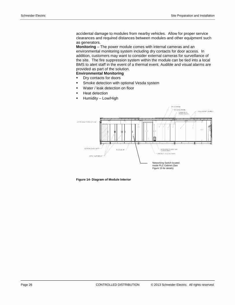
accidental damage to modules from nearby vehicles. Allow for proper service clearances and required distances between modules and other equipment such as generators. Monitoring – The power module comes with internal cameras and an environmental monitoring system including dry contacts for door access. In addition, customers may want to consider external cameras for surveillance of the site. The fire suppression system within the module can be tied into a local BMS to alert staff in the event of a thermal event. Audible and visual alarms are provided as part of the solution. Environmental Monitoring � Dry contacts for doors � Smoke detection with optional Vesda system � Water / leak detection on floor � Heat detection � Humidity – Low/High
Figure 14- Diagram of Module Interior
Networking Switch located inside PLC Cabinet (See Figure 15 for details)
Site Preparation and Installation Schneider Electric
© 2013 Schneider Electric. All rights reserved. CONTROLLED DISTRIBUTION Page 27
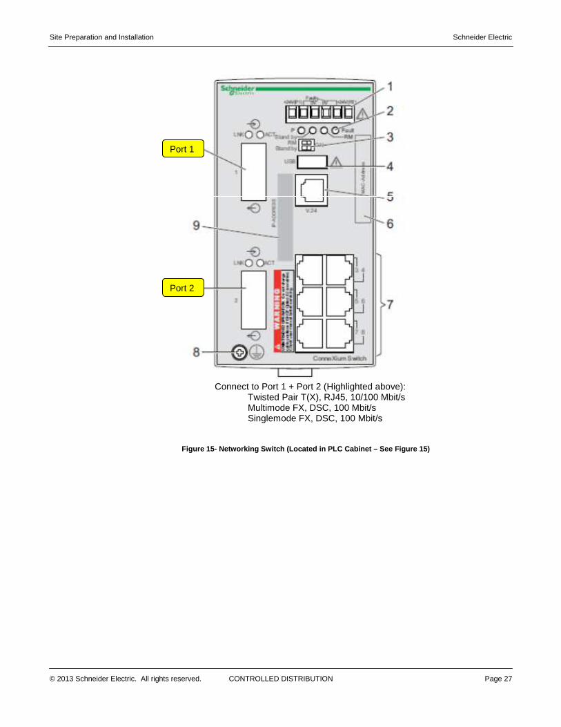
Connect to Port 1 + Port 2 (Highlighted above): Twisted Pair T(X), RJ45, 10/100 Mbit/s Multimode FX, DSC, 100 Mbit/s Singlemode FX, DSC, 100 Mbit/s
Figure 15- Networking Switch (Located in PLC Cabine t – See Figure 15)
Port 2
Port 1