Embed Size (px)
Citation preview

Instruction Manual • Bedienungsanleitung • Manuel d’utilisation • Manuale di Istruzioni
6e6 ®
®

2 SPEKTRUM DX6e • TRANSMITTER INSTRUCTION MANUAL
EN
WARNING: Read the ENTIRE instruction manual to become familiar with the features of the product before operating.
Failure to operate the product correctly can result in damage to the product, personal property and cause serious injury.
This is a sophisticated hobby product. It must be operated with caution and common sense and requires some basic mechanical ability. Failure to operate this Product in a safe and responsible manner could result in injury or damage to the product or other property. This product is not intended for use by children without direct adult supervision. Do not attempt disassembly, use with incompatible compo-nents or augment product in any way without the approval of Horizon Hobby, LLC. This manual contains instructions for safety, operation and maintenance. It is essential to read and follow all the instructions and warnings in the manual, prior to assembly, setup or use, in order to operate correctly and avoid damage or serious injury.
WARNING AGAINST COUNTERFEIT PRODUCTS Always purchase from a Horizon Hobby, LLC authorized dealer to ensure authentic high-quality Spektrum product. Horizon Hobby,
LLC disclaims all support and warranty with regards, but not limited to, compatibility and performance of counterfeit products or products
claiming compatibility with DSM or Spektrum technology.
NOTICE: This product is only intended for use with unmanned, hobby-grade, remote-controlled vehicles and aircraft. Horizon Hobby
disclaims all liability outside of the intended purpose and will not provide warranty service related thereto.
Age Recommendation: Not for Children under 14 years. This is not a toy.
Warranty RegistrationVisit spektrumrc.com today to register your product.
NOTICE: While DSMX allows you to use more than 40 transmitters simultaneously, when using DSM2 receivers, DSMX receivers in
DSM2 mode or transmitters in DSM2 mode, do not use more than 40 transmitters simultaneously.
General Notes • Models are hazardous when operated and maintained incorrectly. • Always install and operate a radio control system correctly. • Always pilot a model so the model is kept under control in all
conditions. • Please seek help from an experienced pilot or your local
hobby store. • Contact local or regional modeling organizations for guidance
and instructions about fl ying in your area. • When working with a model, always power on the transmitter
fi rst and power off the transmitter last. • After a model is bound to a transmitter and the model is set
up in the transmitter, always bind the model to the transmitter again to establish failsafe settings.
Pilot Safety• Always make sure all batteries are fully charged before fl ying. • Time fl ights so you can fl y safely within the time allotted by
your battery.• Perform a range check of the transmitter and the model
before fl ying the model. • Make sure all control surfaces correctly respond to transmitter
controls before fl ying. • Do NOT fl y a model near spectators, parking areas or any
other area that could result in injury to people or damage to property.
• Do NOT fl y during adverse weather conditions. Poor visibility, wind, moisture and ice can cause pilot disorientation and/or loss of control of a model.
• When a fl ying model does not respond correctly to controls, land the model and correct the cause of the problem.
NOTICE
All instructions, warranties and other collateral documents are subject to change at the sole discretion of Horizon Hobby, LLC. For up-to-date
product literature, visit horizonhobby.com and click on the support tab for this product.
Meaning of Special Language
The following terms are used throughout the product literature to indicate various levels of potential harm when operating this product:
NOTICE: Procedures, which if not properly followed, create a possibility of physical property damage AND little or no possibility of injury.
CAUTION: Procedures, which if not properly followed, create the probability of physical property damage AND a possibility of serious injury.
WARNING: Procedures, which if not properly followed, create the probability of property damage, collateral damage and serious injury OR create a high probability of superfi cial injury.

3SPEKTRUM DX6e • TRANSMITTER INSTRUCTION MANUAL
EN
TABLE OF CONTENTSBattery and Charging Precautions and Warnings ................4Box Contents ..........................................................................4Installing the transmitter Batteries.......................................5Installing Optional Lithium Ion Battery Pack ........................5Transmitter Functions ...........................................................6Main Screen ...........................................................................8Navigation ..............................................................................8Auto Switch Select ..................................................................8
SD Card ..................................................................................9Installing the SD Card ..............................................................9Registering the Transmitter with Spektrum ................................9Update Spektrum AirWare™ Software ....................................10
AR620 Receiver Specifi cations ...........................................11Binding .................................................................................11Programming Failsafe Positions .........................................12Model Type Programming Guide .........................................13System Setup .......................................................................14Model Select .........................................................................14Direct Model Access ..............................................................14Model Type ...........................................................................14Model Name .........................................................................15F-Mode Setup .......................................................................15Sailplane Flight Mode Setup ...................................................15Sailplane Flight Mode Table....................................................15
System Setup .......................................................................15Flight Mode Name Setup .......................................................16Channel Assignment..............................................................16Channel Input Confi guration ...................................................16Create New Model.................................................................17Delete Model ........................................................................17Copy Model ..........................................................................17Model Utilities .......................................................................17Model Reset .........................................................................18Sort Model List ......................................................................18Warnings ..............................................................................18Telemetry .............................................................................19Wireless Trainer ....................................................................21SYSTEM SETTINGS ...............................................................22User Name ...........................................................................22Contrast ...............................................................................22Backlight ..............................................................................22Mode ...................................................................................22Selecting a Language ............................................................23Inactive Alarm .......................................................................23System Sounds .....................................................................23Trim Display ..........................................................................23Extra Settings .......................................................................23Exporting the Serial Number to the SD Card ............................24Calibrate ...............................................................................24Calibrating the Transmitter .....................................................24Serial Number .......................................................................24Locating the Transmitter Spektrum AirWare Software Version ...24Transfer SD card ...................................................................25Import Model ........................................................................25Export Model ........................................................................25Update Spektrum AirWare Software ............................................Servo Setup .........................................................................26Travel Adjust .........................................................................26Sub-Trim ..............................................................................26Reverse ................................................................................26
Function list .........................................................................26Differential (ACRO and SAIL Types only) ..................................27Throttle Cut (ACRO and HELI Types only) .................................27Throttle Curve (ACRO and HELI Types only) .............................27D/R & Exponential .................................................................27Mixing ..................................................................................28Assigning a Mix to a Switch ...................................................28Back Mixing ..........................................................................29Range Test ............................................................................29Timer ...................................................................................29Telemetry .............................................................................30System Setup .......................................................................30Monitor.................................................................................30
ACRO (Airplane) ...................................................................31Acro Model Type ..................................................................31Recommended Servo Connections .........................................31Icon ......................................................................................31Aileron..................................................................................32Elevator ................................................................................32Elevon Servo Control .............................................................32Flap System ..........................................................................32ACRO Mixing ........................................................................32Swash Type ..........................................................................33Collective Type ......................................................................33Pitch Curve ...........................................................................33
HELI (Helicopter) ..................................................................33Heli Model Type ....................................................................33Swashplate ...........................................................................34Gyro .....................................................................................34Mixing .................................................................................34
Sail (Sailplane) .....................................................................35Sailplane Model Type .............................................................35Sailplane Type ......................................................................35Camber Preset ......................................................................35Camber System ....................................................................35Motor ...................................................................................35SAIL Mixing ..........................................................................36V-Tail Differential ...................................................................36
MULTI (Multirotor) ................................................................37Multirotor Model Type ............................................................37F-Mode Setup .......................................................................37Trim Setup ............................................................................37D/R & Exponential .................................................................38Motor Cut .............................................................................38Motor Curve .........................................................................38
Physical Transmitter Adjustments ......................................39Ratcheted Throttle – Smooth Throttle Adjustment ....................39Adjust Stick Tension ..............................................................39Control Stick Length Adjustment ...........................................39Safety plug ...........................................................................40Programming Conversion.......................................................40Calibrating ............................................................................40
Troubleshooting Guide .........................................................411-Year Limited Warranty .....................................................42Warranty and Service Contact Information ........................43FCC Information ...................................................................43FAA Information ...................................................................44AMA National Model Aircraft Safety Code ..........................44IC Information ......................................................................44Compliance Information for the European Union ...............44
4 SPEKTRUM DX6e • TRANSMITTER INSTRUCTION MANUAL
EN
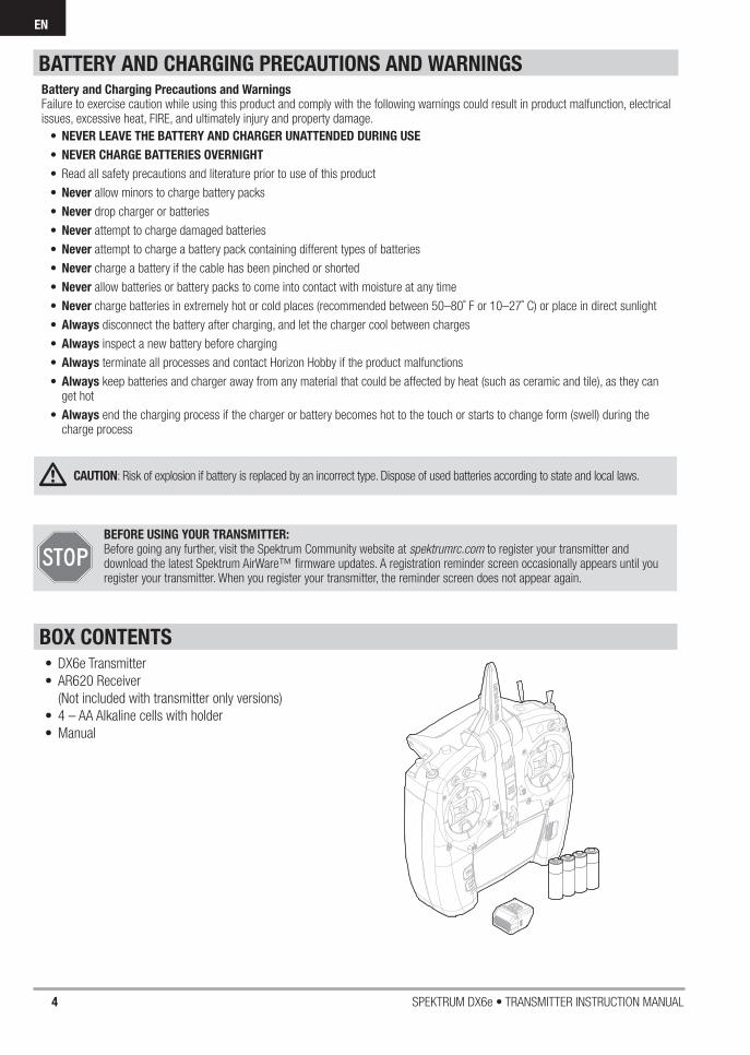
• DX6e Transmitter
• AR620 Receiver
(Not included with transmitter only versions)
• 4 – AA Alkaline cells with holder
• Manual
BEFORE USING YOUR TRANSMITTER: Before going any further, visit the Spektrum Community website at spektrumrc.com to register your transmitter and download the latest Spektrum AirWare™ fi rmware updates. A registration reminder screen occasionally appears until you register your transmitter. When you register your transmitter, the reminder screen does not appear again.
BOX CONTENTS
Battery and Charging Precautions and WarningsFailure to exercise caution while using this product and comply with the following warnings could result in product malfunction, electrical issues, excessive heat, FIRE, and ultimately injury and property damage.
• NEVER LEAVE THE BATTERY AND CHARGER UNATTENDED DURING USE
• NEVER CHARGE BATTERIES OVERNIGHT
• Read all safety precautions and literature prior to use of this product
• Never allow minors to charge battery packs
• Never drop charger or batteries
• Never attempt to charge damaged batteries
• Never attempt to charge a battery pack containing different types of batteries
• Never charge a battery if the cable has been pinched or shorted
• Never allow batteries or battery packs to come into contact with moisture at any time
• Never charge batteries in extremely hot or cold places (recommended between 50–80˚ F or 10–27˚ C) or place in direct sunlight
• Always disconnect the battery after charging, and let the charger cool between charges
• Always inspect a new battery before charging
• Always terminate all processes and contact Horizon Hobby if the product malfunctions
• Always keep batteries and charger away from any material that could be affected by heat (such as ceramic and tile), as they can get hot
• Always end the charging process if the charger or battery becomes hot to the touch or starts to change form (swell) during the charge process
BATTERY AND CHARGING PRECAUTIONS AND WARNINGS
CAUTION: Risk of explosion if battery is replaced by an incorrect type. Dispose of used batteries according to state and local laws.

5SPEKTRUM DX6e • TRANSMITTER INSTRUCTION MANUAL
EN
INSTALLING OPTIONAL LITHIUM ION BATTERY PACK
INSTALLING THE TRANSMITTER BATTERIES
1. Remove battery cover from the back of the transmitter.
2. Remove the AA battery holder and disconnect from the transmitter power port.
3. Remove the Rectangle shaped foam and fl at foam from the battery compartment.
4. Connect the battery pack (SPMA9602) to the transmitter power port.
5. Install the optional Lithium Ion battery pack into the transmitter.
6. Install the battery cover.
NOTICE: When installing a Lithium Ion battery pack, always set the battery chemistry to Lithium Ion in the Systems Setting screen to correctly set the low voltage alarm.
1. Remove battery cover from the back of the transmitter.
2. Install the included 4 AA batteries into the battery holder.
3. Install the battery cover.
The optional Li-Ion battery has an internal charger designed to quick charge at a rate of 0.5 amps. The charge port on the battery is not polarity-dependent.
NOTICE: Never connect an external battery charger to your DX6e transmitter.
Always charge the transmitter on a heat-resistant surface.
1. Power off your transmitter.
2. Connect the power supply (SPM9551) connector to the Li-Ion charge port located under the rubber fl ap on the battery door.
3. Connect the power supply to a power outlet using the appropriate adapter.
4. Disconnect the transmitter from the power supply once charging is complete and disconnect the power supply from the power outlet.
CAUTION: Never leave a charging battery unattended.
CAUTION: Never charge a battery overnight.
Battery Alarm
The System Settings Screen allows you to change the battery type and low voltage alarm settings. See “System Settings” for more information.
• An alarm will sound when the battery reaches the low voltage limit (6.4V for LiPo/Li-Ion).
CAUTION: Never change the low voltage limit for LiPo/Li-Ion batteries from 6.4V. Doing so could over-
discharge the battery and damage both battery and transmitter.
CHARGING THE LITHIUM ION BATTERY PACK

6 SPEKTRUM DX6e • TRANSMITTER INSTRUCTION MANUAL
EN
Function
1 LED
2Elevator Trim (Mode 2, 4)
Throttle Trim (Mode 1, 3)
3 Switch H
4 Switch G
5 Switch F
6
Throttle Tension Adjustment
Throttle Ratchet Adjustment
(Mode 1,3)
7
Throttle/Aileron Stick
(Mode 1)Elevator/Aileron Stick
(Mode 2) Throttle/Rudder Stick
(Mode 3)Elevator/Rudder Stick
(Mode 4)
Function
8Left/Right Gimbal Stick
Tension Adjustment
9Up/Down Gimbal Stick
Tension Adjustment
10Aileron Trim (Mode 1,2)
Rudder Trim (Mode 3,4)
11 Neck Strap Mount
12 Scroll wheel
13 LCD
14 Buzzer Grill
15 Back Button
16 Clear Button
17Rudder Trim (Mode 1,2)
Aileron Trim (Mode 3,4)
Function
18
Throttle Tension Adjustment
Throttle Ratchet Adjustment
(Mode 2,4)
19
Elevator/Rudder Stick
(Mode 1)Throttle/Rudder Stick
(Mode 2)Elevator/Aileron Stick
(Mode 3)Throttle/Aileron Stick
(Mode 4)
20Left/Right Gimbal Stick
Tension Adjustment
21Up/Down Gimbal Stick
Tension Adjustment
22 Switch D
23 Switch B
Function
24 Switch C
25 Bind/Switch I
26Elevator Trim (Mode 1,3)
Throttle Trim (Mode 2,4)
27 On/Off Switch
28 Antenna
The transmitter comes with a thin,
clear plastic fi lm applied to some
front panels for protection during
shipping. Humidity and use may
cause this fi lm to come off. Carefully
remove this fi lm as desired.
TRANSMITTER FUNCTIONS
1
4
5
2
3
6
7
8
9
10
11
12
1314
15
16
17
18
19
20
21
23
22
24
25
26
2728

7SPEKTRUM DX6e • TRANSMITTER INSTRUCTION MANUAL
EN
1
2
3
45
6
7
8
9
Function
1 Switch A
2 Handle
3 Saftey Plug
4 SD Card Opening
5Charge Port For use with
optional Lithium Ion Battery
6 Battery Cover
Function
7 Mode change door
8 Mode change slider
9 Antenna rotation tension
TRANSMITTER FUNCTIONS
Powering the DX6e On and Off
1. Press the power button to turn on the DX6e.
2. Press and hold the power button for about 4 seconds to power off the DX6e.

8 SPEKTRUM DX6e • TRANSMITTER INSTRUCTION MANUAL
EN
• Scroll the scroll wheel to move through the screen content or change programming values. Press the scroll wheel to make a selection.
• Use the Back button to go to the previous screen (for example, to go from the Mixing Screen to the Function List).
• Use the Clear button to return a selected value on a screen to the default setting.
• Direct Model Access enables you to access the Model Select screen without powering off the transmitter. Anytime the transmitter power is on, press the Clear and Back buttons to access the Model Select screen.
• Press and hold the scroll wheel while powering on the transmitter to show the System Setup list. No radio transmission occurs when a System Setup screen is displayed, preventing accidental damage to linkages and servos during changes to programming.
• At the main screen you can scroll to view the servo monitor.
• The Main Screen appears when you power on the transmitter. Press the scroll wheel once to display the Function List.
• When you want to change a value in a screen for a particular control position, move the control to the desired position to highlight the value you want to change, such as 0/1/2, up/down or left/right.
Enter, Choose or Exit
Move between options or change value in an option
Hold for 3 seconds and release to move to the Main Screen
Turn HoldPressTip: The tick mark below shows the current switch position.Rolling and clicking the scroll wheel turns the selected box black, indicating that the value or condition will act on that position.
Function
A Model Name
DSMX/DSM2 If not shown, this indicates “not bound”.
C Transmitter Battery Charge Level
D
Digital Battery Voltage (an alarm sounds and the screen fl ashes when battery charge gets down to 4.3V when using Alkaline Batteries or 6.4V for a LiPo/Li Ion battery.)
E Model Type
FElevator Trim (Modes 2 and 4) Throttle Trim (Modes 1 and 3)
GAileron Trim (Modes 1 and 2) Rudder Trim (Modes 3 and 4)
H Model Memory Timer
Function
IRudder Trim (Modes 1 and 2) Aileron Trim (Modes 3 and 4)
JThrottle Trim (Mode 2 and 4) Elevator Trim (Mode 1 and 3)
K Timer
MAIN SCREEN
NAVIGATION
Auto Switch Select
To easily select a switch in a function, such as a program mix, roll with the scroll wheel to highlight the switch selection box, and press the scroll wheel. The box around the switch should now fl ash. To select a switch, toggle the switch you wish to select. Verify the switch selection is now displayed as desired. When correct, press the scroll wheel to select this switch and complete the switch selection.
E
DCB
J
K
A
F
GI H
B

9SPEKTRUM DX6e • TRANSMITTER INSTRUCTION MANUAL
EN
SD CARDInstalling the SD Card
The SD Card (not included) enables you to:• Import (copy) models from any compatible Spektrum
AirWare™ transmitter
• Export (transfer) models to any SpektrumAirWare transmitter*
• Update Spektrum AirWare software in the transmitter
• Install/Update sound fi les
To install the SD Card:
1. Power off the transmitter.
2. Remove the battery door.
3. Press the SD Card into the card slot with the card label facing up as shown.
Registering the Transmitter with Spektrum
Exporting the transmitter serial number to the SD Card allows you to upload the serial number directly into the registration screen at www.spektrumrc.com.
To export the serial number:1. Press and hold the scroll wheel while powering the
transmitter on until the System Setup list appears.
2. Scroll to the System Settings menu. Press the scroll wheel once to open the menu.
3. Select NEXT on the System Settings and Extra Settings screens.
4. When the Serial Number screen appears, select EXPORT.
5. Power off the transmitter and remove the SD Card from the transmitter.
To Upload the serial number to www.spektrumrc.com:1. Insert the SD Card in your computer and check the contents of
the SD card on your computer for a “My_DX6e.xml” fi le.
2. In your favorite browser navigate to www.spektrumrc.com and fi nd the Product Registration link on the top of the page as shown.
3. If you do not already have an account, create one now. If you have an account login in with your secure login.
4. Once logged in go to the “My Spektrum” page. Fill out all relevant information. Once you select your transmitter model from the pull down menu you will be asked to upload the serial number.
5. Click on the Select button to navigate to the “My_DX6e.xml” fi le on the SD card that is in your computers SD card reader and select the fi le.
6. Click on the Upload from xml fi le... button and the serial number will populate into the Serial Number fi elds.
7. Click REGISTER at the bottom of the screen to fi nish registering your new Spektrum Transmitter.
Alternately you can copy the serial number from the .xml fi le and paste directly into the Serial Number fi eld.
Screen shots from www.spektrumrc.com are correct at time of printing but may change at a future date.

10 SPEKTRUM DX6e • TRANSMITTER INSTRUCTION MANUAL
EN
Update Spektrum AirWare™ Software
NOTICE: The orange LED Spektrum bars fl ash and a status bar appears on the screen when AirWare software updates are installing. Never power off the transmitter when updates are installing. Doing so may damage the system fi les.
NOTICE: Before installing any Spektrum AirWare fi les, always Export All Models to an SD Card separate from the SD Card containing the update. The update may erase all model fi les.
For more information on AirWare software updates, visit www.spektrumrc.com
Automatically Installing Spektrum AirWare Software Updates
1. In your favorite browser navigate to www.spektrumrc.com and fi nd the Firmware Updates link inside the Setups/Updates tab on the top of the page as shown.
2. fi nd your registered transmitter in the MY PRODUCTS list and click on Download Updates. Follow directions on the screen for downloading the update to your computer and SD card.
3. Eject the SD card from the computer.
4. Make sure the transmitter is powered off and install the SD card into the transmitter.
5. Power on the transmitter and the update automatically installs in the transmitter.
Manually Installing Spektrum AirWare Software Updates
1. Save the desired Spektrum AirWare version to the SD Card.
2. Install the SD card into the transmitter.
3. Select Update Firmware in the SD Card Menu options. The Select File screen appears.
4. Select the desired Spektrum AirWare version from the File List. When updates are installing, the transmitter screen is dark. The orange LED Spektrum bars fl ash and the update status bar appears on the screen.
NOTICE: Do not power off the transmitter when updates are installing. Doing so will damage the transmitter.
Screen shots from www.spektrumrc.com are correct at time of printing but may change at a future date.
SD CARD
11SPEKTRUM DX6e • TRANSMITTER INSTRUCTION MANUAL
EN
BINDINGBinding is the process of programming the receiver to recognize the GUID (Globally Unique Identifi er) code of a single specifi c transmitter. You must bind the receiver to your transmitter before it will operate. To put the transmitter in bind mode, press the Bind Button while powering on the transmitter
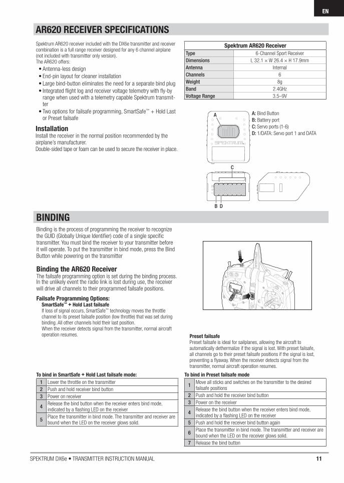
AR620 RECEIVER SPECIFICATIONS
A
C
B D
Spektrum AR620 Receiver
Type 6-Channel Sport Receiver
Dimensions L 32.1 × W 26.4 × H 17.9mm
Antenna Internal
Channels 6
Weight 8g
Band 2.4GHz
Voltage Range 3.5–9V
A: Bind Button
B: Battery port
C: Servo ports (1-6)
D: 1/DATA: Servo port 1 and DATA
To bind in SmartSafe + Hold Last failsafe mode:
1 Lower the throttle on the transmitter
2 Push and hold receiver bind button
3 Power on receiver
4Release the bind button when the receiver enters bind mode, indicated by a fl ashing LED on the receiver
5Place the transmitter in bind mode. The transmitter and receiver are bound when the LED on the receiver glows solid.
To bind in Preset failsafe mode
1Move all sticks and switches on the transmitter to the desired failsafe positions
2 Push and hold the receiver bind button
3 Power on the receiver
4Release the bind button when the receiver enters bind mode, indicated by a fl ashing LED on the receiver
5 Push and hold the receiver bind button again
6Place the transmitter in bind mode. The transmitter and receiver are bound when the LED on the receiver glows solid.
7 Release the bind button
InstallationInstall the receiver in the normal position recommended by the airplane’s manufacturer.Double-sided tape or foam can be used to secure the receiver in place.
Spektrum AR620 receiver included with the DX6e transmitter and receiver combination is a full range receiver designed for any 6 channel airplane (not included with transmitter only version).The AR620 offers:
• Antenna-less design
• End-pin layout for cleaner installation
• Large bind-button eliminates the need for a separate bind plug
• Integrated fl ight log and receiver voltage telemetry with fl y-by range when used with a telemetry capable Spektrum transmit-ter
• Two options for failsafe programming, SmartSafe™ + Hold Last or Preset failsafe
Preset failsafePreset failsafe is ideal for sailplanes, allowing the aircraft to automatically dethermalize if the signal is lost. With preset failsafe, all channels go to their preset failsafe positions if the signal is lost, preventing a fl yaway. When the receiver detects signal from the transmitter, normal aircraft operation resumes.
Binding the AR620 ReceiverThe failsafe programming option is set during the binding process. In the unlikely event the radio link is lost during use, the receiver will drive all channels to their programmed failsafe positions.
Failsafe Programming Options:SmartSafe™ + Hold Last failsafeIf loss of signal occurs, SmartSafe™ technology moves the throttle channel to its preset failsafe position (low throttle) that was set during binding. All other channels hold their last position. When the receiver detects signal from the transmitter, normal aircraft operation resumes.

12 SPEKTRUM DX6e • TRANSMITTER INSTRUCTION MANUAL
EN
You establish failsafe positions when you bind your transmitter and receiver. If the radio signal connection is lost between the transmitter and receiver, the receiver immediately moves the aircraft control surfaces to the failsafe positions. If you assign the receiver THRO channel to a transmitter channel other than throttle, we recommend using Preset failsafe with the throttle in the low position.
NOTICE: Failsafe features vary according to receiver. Always consult the receiver instruction manual for failsafe features.
Before fl ight, ALWAYS confi rm the failsafe functions as you would expect.
SmartSafe™ Failsafe
SmartSafe failsafe is a technology that only acts on the throttle channel and offers the following benefi ts:
• Prevents electric motors from operating when the receiver power is on and the transmitter power is off.
• Prevents the speed controller from arming until the throttle is moved to the low throttle position.
• Powers off an electric motor and reduces gas/glow engines to idle if signal is lost.
To Program SmartSafe, move the throttle to the low or off position before putting the transmitter into bind mode.
To Test the SmartSafe failsafe
1. Power the transmitter and receiver on.
2. Power off the transmitter. The throttle should immediately move to the failsafe position.
CAUTION: Make sure the aircraft is fully restrained on the ground. If the failsafe is not set correctly, your aircraft might
advance to mid or full throttle.
Hold Last Command
The Hold Last Command failsafe maintains the last command on all channels except throttle. If the radio signal is lost, the aircraft maintains the commanded control inputs until the receiver regains signal.To program Hold Last Command, follow the provided binding instructions in this instruction manual.
To Test Hold Last Command:1. Power on the transmitter and receiver.
2. Move one of the control sticks to the desired Hold Last Command position and hold the input.
3. While holding the control input (for example, a small amount of rudder) power off the transmitter. The rudder should maintain the input command.
CAUTION: Make sure the aircraft is fully restrained on the ground. If the failsafe is not set correctly, the aircraft throttle
might advance to mid or full throttle.
Preset Failsafe
The Preset failsafe moves all channels to their programmed failsafe positions. We recommend using Preset failsafe to deploy spoilers on sailplanes to prevent a fl yaway if the radio signal is lost.
To program Preset failsafe:1. Insert the bind plug in the bind port on the receiver and power
on the receiver.
2. Remove the bind plug when the orange LED on the main receiver and all attached remote receivers fl ash rapidly. The orange receiver LEDs will continue fl ashing.
3. Move the transmitter control sticks and switches to the desired Preset failsafe position. Power the transmitter on.
4. Failsafe programming is complete when the orange LEDs on the transmitter and all receivers turn solid.
CAUTION: Make sure the aircraft is fully restrained on the ground. If the failsafe is not set correctly, the aircraft throttle
might advance to mid or full throttle.
PROGRAMMING FAILSAFE POSITIONS

13SPEKTRUM DX6e • TRANSMITTER INSTRUCTION MANUAL
EN
MODEL TYPE PROGRAMMING GUIDEMenu options show up on model type selection. These menu options vary between Model Types (Airplane, Helicopter and Sailplane), but are identical for all models in that type. Subsequent aircraft type (Aircraft, Swashplate or Sailplane) selections make other menu options appear.
System Setup List:Model SelectModel Type Model NameAircraft TypeF-Mode SetupFlight Mode Name SetupChannel AssignModel UtilitiesWarningsTelemetry BindTrainerDigital Switch SetupSystem SettingsTransfer SD Card
Function List: Servo SetupD/R and ExpoDifferential V-Tail Differential Throttle CutThrottle CurveFlap System MixingRange TestTimerTelemetry System SetupMonitor
System Setup List:Model SelectModel Type Model NameSwashplate Type F-Mode SetupFlight Mode Name SetupChannel AssignModel UtilitiesWarningsTelemetry BindTrainerDigital Switch SetupSystem SettingsTransfer SD Card
Function List: Servo SetupD/R and ExpoThrottle Cut Throttle Curve Pitch Curve Swashplate Gyro MixingRange TestTimerTelemetrySystem SetupMonitor
System Setup List:Model SelectModel Type Model NameAircraft Type F-Mode SetupFlight Mode Name SetupChannel AssignModel UtilitiesWarningsTelemetry Preflight SetupBindTrainerDigital Switch SetupSystem SettingsTransfer SD Card
Function List: Servo SetupD/R and ExpoThrottle Cut Throttle Curve Pitch Curve Camera Gimbal Motor CutMotor Curve MixingSequencerRange TestTimerTelemetrySystem SetupMonitor
System Setup List:Model SelectModel Type Model NameSailplane TypeF-Mode SetupFlight Mode Name SetupChannel AssignModel UtilitiesWarningsTelemetry BindTrainerDigital Switch SetupSystem SettingsTransfer SD Card
Function List: Servo SetupD/R and ExpoDifferential V-Tail Differential Throttle CutMotor Curve Camber Presets Camber System MixingRange TestTimerTelemetrySystem Setup Monitor

14 SPEKTRUM DX6e • TRANSMITTER INSTRUCTION MANUAL
EN
Press and hold the scroll wheel while powering on the transmitter to show the System Setup list. No radio transmission occurs when a System Setup screen is displayed, preventing accidental damage to linkages and servos during changes to programming.
You can also enter the System Setup from the Function list without turning the transmitter off. A Caution screen will appear that warns that RF will be disabled (the transmitter will no longer transmit). Press YES if you are sure and want to access the System List. If you are not sure, press NO to exit to the main screen and continue operation.If you do not press YES or NO, the system will exit to the main screen and continue operation within approximately 10 seconds.
WARNING: Do not press YES unless the model is turnedoff or the model is secured.
Model Select
Model Select enables you to access any of the 250 internal model memory locations in the Model Select list.
1. Scroll to the desired model memory in the Model Select list.
2. When the desired model memory is highlighted, press the scroll wheel once to select the model. The transmitter returns to the System Setup List.
3. Add a new model by rolling to the bottom of the list. You will then be prompted with the Create New Model screen, with the option to create a new model or cancel. If you select Cancel, the system will return to the Model Select function. If you select Create, the new model will be created and now be available in the model select list.
Direct Model AccessPress the Clear and Back buttons from the Main Screen or a telemetry screen to access Model Select.
SYSTEM SETUP
Model Type
Select from Airplane, Helicopter, Sailplane or Multirotor model types.
IMPORTANT: When you select a new model type, you will delete any programming data in the current model memory. Always confi rm the desired model memory before changing model types. It will be necessary to re-bind after resetting the model type.
To change the model type:1. Scroll to the desired model type and press the scroll wheel.
The Confi rm Model Type screen appears.
2. Select Yes and press the scroll wheel to confi rm the model type. All data will be reset. Selecting No will exit the Confi rm Model Type screen and return to the Model Type screen.

15SPEKTRUM DX6e • TRANSMITTER INSTRUCTION MANUAL
EN
F-Mode Setup
Use the Flight Mode Setup menu to assign switches to fl ight modes.
Sailplane Flight Mode SetupYou can assign up to fi ve fl ight modes using any combination of up to two switches. You can also assign a priority switch. When the priority switch position is active, only the current fl ight modeis active, regardless of other switch positions.
Sailplane Flight Mode TableYou can assign the available fl ight modes (up to 5 for Sail) to each of the switch positions (up to 2 switches can be used for sailplane). Press NEXT from the Flight Mode Name page to access the fl ight mode table assignment page when Custom fl ight mode has been selected in the Flight Mode Setup page. The combination of up to 2 switches can be used to access all of the fl ight modes available.
Mode Number of SwitchesNumber of Flight
Modes
Aircraft 1 up to 3
Heli 2 (including Throttle Hold) 4 (including Throttle Hold)
Number
of Flight
Modes
2 3 3* 4 4 5
Switch 1
(number of
positions)
2P 3P 2P 2P 3P 3P
Switch 2
(number of
positions)
2P 3P 2P 3P
Flight
Mode
1
Launch Launch Launch Launch Launch Launch
2 Cruise Cruise Cruise Cruise Cruise Cruise
3 Land Land Land
4 Thermal Thermal Thermal Thermal
5 Speed Speed
*Must be set up in a 4/5 fl ight mode.
SYSTEM SETUP
Model Name
Model Name enables you to assign a custom name to the current model memory. Model names can include up to 20 characters, including spaces.
To add letters to a Model Name:1. Scroll to the desired letter position and press the scroll wheel
once. A fl ashing box appears.
2. Scroll left or right until the desired character appears. Press the scroll wheel once to save the character.
3. Scroll to the next desired letter position. Repeat Steps 1 and 2 until the Model Name is complete.
4. Select BACK to return to the System Setup list.
To erase a character:
1. Press CLEAR while the character is selected.
2. Press CLEAR a second time to erase all characters to the right of the cursor.
Aircraft Type This menu only available in Airplane Mode. See ACRO (Airplane) section for set up.Sailplane Type This menu only available in Sailplane Mode. See SAIL (Sailplane) section for set up.Swash Type This menu only available in Helicopter Mode. See HELI (Helicopter) section for set up.

16 SPEKTRUM DX6e • TRANSMITTER INSTRUCTION MANUAL
EN
Flight Mode Name Setup
The Flight Modes Name function allows the fl ight modes to be renamed throughout the menus.
To change the Flight Mode name:1. Enter the Flight Mode Names function after setting up the fl ight
modes.
2. Select the fl ight mode you want to rename, and enter the name
as desired.
3. Press back in the Edit Flight Mode Name screen to return to the main Flight Mode Names screen.
Channel Assignment
The Channel Assignment function allows you to reassign almost any receiver channel to a different transmitter channel. For example, the receiver gear channel could be re-assigned to the transmitter throttle channel.
1. Scroll to the receiver channel you wish to change.
2. Press the scroll wheel once and scroll left or right to change the receiver input selection.
3. Press the scroll wheel a second time to save the selection.
IMPORTANT: You cannot assign a mix to a channel that has been moved. Create the mix fi rst, then move the channel.
Channel Input Confi guration
The Channel Input Confi guration screen enables you to assign a transmitter channel to a different control stick or switch.
1. Select NEXT on the RX Port Assignments screen to access the Channel Input Confi guration screen.
2. Scroll to the transmitter channel you wish to re-assign and press the scroll wheel. The box around the current input selection fl ashes.
3. Scroll left or right to select the desired control stick or switch.
4. Press the scroll wheel to save the selection.
SYSTEM SETUP

17SPEKTRUM DX6e • TRANSMITTER INSTRUCTION MANUAL
EN
MODEL UTILITIES
In the Model Utilities function you can create a new model, delete a model, copy a model, reset a model to default settings andsort the model list.
Create New Model
Use this selection to create a new model in the model select list.
1. Select Create New Model. Within this screen, you will have the option to create a new model or cancel.
2. If you select Cancel, the system will return to the Model Select function.
3. If you select Create, the new model will be created and now be available in the model select list.
SYSTEM SETUP
Delete Model
Use this selection to permanently delete a model from the model select list. If you do not wish to delete a model, select Cancel to exit the page.
1. To delete a model, highlight the model listed. Press to select then roll to the model name. Press the scroll wheel to select.
2. Select DELETE to delete the model.
Copy Model
The Model Copy menu enables you to duplicate model programming from one Model List location to another.
Use Model Copy to:• Save a default model copy before experimenting with
programming values
• Expedite programming for a model using a similar programming setup
IMPORTANT: Copying a model program from one model memory to another will erase any programming in the “To” model memory.
To copy model programming:
1. Make sure the model program you wish to copy is active. If the desired model program is not active, select Cancel and change the active model in the Model Select menu.
2. Select the model memory next to “To” and scroll to the desired model memory. Press the scroll wheel once to save the selection.
3. Select Copy and the Confi rm Copy screen appears.
4. Select Copy to confi rm. Selecting Cancel will return to the System Setup screen.
5. Select the “To” model as the current model, then bind the transmitter and receiver. Copying a model does not copy the bind from the original model.
You cannot use the Model Copy screen to copy model programming to an SD Card. To copy model programming to the SD Card, please see “Transfer SD Card”.
18 SPEKTRUM DX6e • TRANSMITTER INSTRUCTION MANUAL
EN
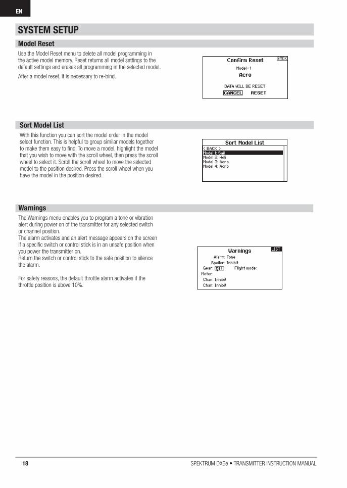
Model Reset
Use the Model Reset menu to delete all model programming in the active model memory. Reset returns all model settings to the default settings and erases all programming in the selected model.
After a model reset, it is necessary to re-bind.
Sort Model List
With this function you can sort the model order in the model select function. This is helpful to group similar models together to make them easy to fi nd. To move a model, highlight the model that you wish to move with the scroll wheel, then press the scroll wheel to select it. Scroll the scroll wheel to move the selected model to the position desired. Press the scroll wheel when you have the model in the position desired.
SYSTEM SETUP
Warnings
The Warnings menu enables you to program a tone or vibration alert during power on of the transmitter for any selected switch or channel position. The alarm activates and an alert message appears on the screen if a specifi c switch or control stick is in an unsafe position when you power the transmitter on.Return the switch or control stick to the safe position to silence the alarm.
For safety reasons, the default throttle alarm activates if the throttle position is above 10%.

19SPEKTRUM DX6e • TRANSMITTER INSTRUCTION MANUAL
EN
TELEMETRY
Installing the optional telemetry module and sensors enables the display of aircraft performance data on the transmitter screen. You can also enable Data Logging to save a telemetry fi le on the SD Card and view the data in the Spektrum STiTM mobile application.
Telemetry Settings
Display
Telemetry display options include:
Tele: When you press the scroll wheel, the Telemetry screens appear and the Main Screen is disabled.
Main: Telemetry alerts appear on the Main screen, but all Telemetry screens are disabled.
Roller (Default): Allows you to toggle between the Telemetry screens and the main screen by pressing the scroll wheel.
Auto: The Telemetry screen automatically appears as soon as the transmitter receives data from the telemetry module.
Units
Scroll to Units and press the scroll wheel to change between US and Metric.
Telemetry Auto-Confi guration
IMPORTANT: The Auto-Confi g option is not available from the System Setup>Telemetry menu. RF signal must be transmitting when you use the Auto-Confi g option. When the System Setup menu is active, RF signal is off.
The DX6e transmitter features telemetry Auto-Confi guration, allowing the transmitter to detect new telemetry sensors.
To use Telemetry Auto-Confi g:1. Make sure all telemetry components are bound to the
transmitter and receiver.2. Power on the transmitter, then power on the receiver.3. Select Telemetry from the Function List, then select Auto
Confi g. “Confi guring” fl ashes for 5 seconds and any new sensors appear in the list.
4. Adjust the sensor alert values as necessary.
Status Reports:Status Reports determines how often the transmitter refreshes the data on the screen. Each telemetry sensor can be adjusted independently.
For example, the RPM status report can refresh every 10 seconds while the altimeter sensor refreshes every 15 seconds.
Warning Reports:Warning Reports determines how often a telemetry alert occurs, if an alert is active.
SYSTEM SETUP

20 SPEKTRUM DX6e • TRANSMITTER INSTRUCTION MANUAL
EN
Telemetry Alarms
Select Inh under Alarm to select the type of alarm desired. Options include Inh, Tone.
File Settings
This is used to select the data logging settings.
File Name
1. Select File Name to assign a custom fi le name.
2. The File Name screen appears, allowing you to name the fi le as you would for a Model Name or Flight Mode Name. The fi le name can include a maximum of 8 characters.
3. Press BACK to save the name.
Start
1. Select Start to assign a specifi c switch position or stick position that activates Data Logging.
2. Press the scroll wheel once to save the selection.
Enabled
When Enabled is set to NO, Data Logging is turned off.Select YES to save Telemetry data to the SD Card. The SD Card must be installed in the transmitter to select YES.
CAUTION: If you access the Telemetry menu from the Function List, you may see a Frame Loss appear when you
exit the menu. The Frame Loss is not an error, but there will be a momentary loss of radio signal when exiting the Telemetry screen. DO NOT access the Telemetry menu during fl ight.
BindThe Bind menu enables you to bind a transmitter and receiver without powering off the transmitter. This menu is helpful if you are programming a model and need to bind the receiver for failsafe positions.See “Programming Failsafe Positions” for more information.
SYSTEM SETUP
21SPEKTRUM DX6e • TRANSMITTER INSTRUCTION MANUAL
EN
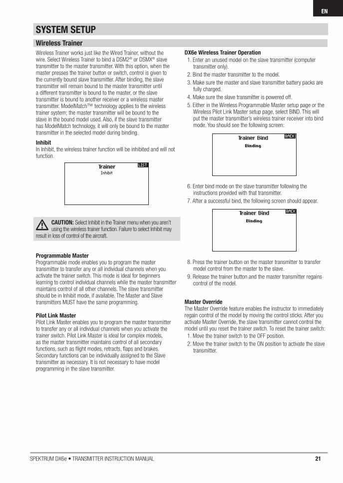
Wireless Trainer
Wireless Trainer works just like the Wired Trainer, without the wire. Select Wireless Trainer to bind a DSM2® or DSMX® slave transmitter to the master transmitter. With this option, when the master presses the trainer button or switch, control is given to the currently bound slave transmitter. After binding, the slave transmitter will remain bound to the master transmitter until a different transmitter is bound to the master, or the slave transmitter is bound to another receiver or a wireless master transmitter. ModelMatch™ technology applies to the wireless trainer system; the master transmitter will be bound to the slave in the bound model used. Also, if the slave transmitter has ModelMatch technology, it will only be bound to the master transmitter in the selected model during binding.
InhibitIn Inhibit, the wireless trainer function will be inhibited and will not function.
CAUTION: Select Inhibit in the Trainer menu when you aren’t using the wireless trainer function. Failure to select Inhibit may
result in loss of control of the aircraft.
Programmable MasterProgrammable mode enables you to program the master transmitter to transfer any or all individual channels when you activate the trainer switch. This mode is ideal for beginners learning to control individual channels while the master transmitter maintains control of all other channels. The slave transmitter should be in Inhibit mode, if available. The Master and Slave transmitters MUST have the same programming.
Pilot Link MasterPilot Link Master enables you to program the master transmitter to transfer any or all individual channels when you activate the trainer switch. Pilot Link Master is ideal for complex models, as the master transmitter maintains control of all secondary functions, such as fl ight modes, retracts, fl aps and brakes.Secondary functions can be individually assigned to the Slave transmitter as necessary. It is not necessary to have model programming in the slave transmitter.
DX6e Wireless Trainer Operation
1. Enter an unused model on the slave transmitter (computer transmitter only).
2. Bind the master transmitter to the model.
3. Make sure the master and slave transmitter battery packs are fully charged.
4. Make sure the slave transmitter is powered off.
5. Either in the Wireless Programmable Master setup page or the Wireless Pilot Link Master setup page, select BIND. This will put the master transmitter’s wireless trainer receiver into bind mode. You should see the following screen:
6. Enter bind mode on the slave transmitter following the instructions provided with that transmitter.
7. After a successful bind, the following screen should appear.
8. Press the trainer button on the master transmitter to transfer model control from the master to the slave.
9. Release the trainer button and the master transmitter regains control of the model.
Master OverrideThe Master Override feature enables the instructor to immediately regain control of the model by moving the control sticks. After you activate Master Override, the slave transmitter cannot control the model until you reset the trainer switch. To reset the trainer switch:
1. Move the trainer switch to the OFF position.
2. Move the trainer switch to the ON position to activate the slave transmitter.
SYSTEM SETUP

22 SPEKTRUM DX6e • TRANSMITTER INSTRUCTION MANUAL
ENEN
SYSTEM SETTINGS
The System Settings menu consists of four screens:
System Settings, Extra Settings, Serial Number and Calibrate. Select
NEXT or PREV to move between screens.
User Name
The User Name fi eld displays your name in the lower right corner of the main screen.
To Program a User Name:1. Scroll to User Name and press the scroll wheel. The User
Name screen appears.
2. Scroll to the desired character position and press the scroll wheel. Scroll left or right to change the character and press the scroll wheel to save the selection. The User Name can contain a maximum of 20 characters, including spaces.
3. Press the Back button to save the User Name and return to the System Settings screen.
Contrast
To adjust the screen contrast:1. Scroll to Contrast and press the scroll wheel.
2. Scroll left or right to adjust the contrast value. Lower numbers lighten the contrast, higher numbers darken it.
3. Press the scroll wheel once to save the selection.
Backlight
The Backlight fi eld adjusts the backlight appearance time and brightness. You have the option to turn the backlight off for models you fl y during the day and turn the backlight on for night fl ying models.
The backlight time options are:Off: Appears for a short time when you power on the transmitter.
On: The backlight is always on.
Set Time: The backlight is on for 3, 10, 20, 30, 45 or 60 seconds before automatically turning off. Press the scroll wheel once to turn the backlight on.
The backlight percentage adjusts the backlight intensity and it is adjustable in 10% increments from 10% (darker) to 100% (brighter).
Mode
You can easily change the transmitter Modes from 1, 2, 3 and 4. Use the slider found on the back of the transmitter to change between modes (2,4) and (1,3).*Finish the mode change by following the programming steps below.
To change the gimbal stick mode:1. Scroll to Mode and press the scroll wheel.
2. Scroll left or right to change the gimbal stick mode. Press the scroll wheel to save the selection.
3. Select NEXT in the lower left corner until the Calibration screen appears.
4. Move all transmitter controls to the center position and complete the calibration process before exiting the System Settings menu. See “Calibrating Your Transmitter” for more information.
*For more information, see Physical Transmitter Adjustments in the back of the manual
Battery AlarmBattery Alarm enables you to change the transmitter battery type and the alarm voltage limit. The alarm activates when the battery reaches the low voltage limit.
To change the battery alarm:1. Scroll to the battery type and press the scroll wheel once
to change the type to LiPo/Li-Ion or NiMH.
2. Scroll to the battery voltage and press the scroll wheel. Turn the scroll wheel left or right to change the voltage level. Press the scroll wheel again to save the selection.
CAUTION: Never select NiMH when a LiPo/Li-Ion battery is installed in the transmitter. Doing so may over-discharge
the LiPo battery and damage the battery, transmitter or both.
CAUTION: Never adjust the low voltage limit for the LiPo/ Li-Ion battery pack below 6.4V. Doing so could over-
discharge the battery pack and damage both battery pack and transmitter.
SYSTEM SETUP

23SPEKTRUM DX6e • TRANSMITTER INSTRUCTION MANUAL
EN
Extra Settings
Selecting a Language
In the Systems Settings screen, scroll to highlight Language, then press the scroll wheel to select the Language function. Scroll to select the desired Language. When the desired Language is selected, press the scroll wheel to accept that Language. Names you input will not be affected by language change. After changing the language for the text, you may also want to change the language for the spoken alerts. See the “Spoken” and “SD Card” sections for more information.
Inactive Alarm
An alarm activates if the transmitter sees a period of inactivity for a certain amount of time. The alarm is helpful in reminding you to power off the transmitter and avoiding a situation where the transmitter battery completely discharges.
The Inactive Alarm options are:
To change the Inactive alarm time:
1. Scroll to the current alarm time and press the scroll wheel.
2. Scroll left or right to change the alarm time. Press the scroll wheel to save the selection.
The Extra Settings screen enables you to:• Turn sounds off or on
• Change the appearance of the trim indicators
• Inh (No alarmsounds)
• 5 min
• 10 min (Default)
• 30 min
• 60 min
System Sounds
Scrolling to System Sounds and pressing the scroll wheel turns sounds on (Active) or off (Inhibit).
You may disable all sounds by changing the volume to 0.
Trim Display
Trim display changes the shape of the trim indicators on the Main Screen. Display options include:
• Boxed Boxes (Default)– The indicators appear as anoutlined box when you adjust the trim.
• Boxed Arrows– The indicators appear as outlined arrows when you adjust the trim.
• INH– The indicators appear as arrows on lines when you adjust the trim.
Inhibit removes all trim bars and indicators from the Main Screen.
To change the Trim Display:
1. Scroll to Trim Display and press the scroll wheel once.
2. Scroll left or right to change the Trim Display option. Press the scroll wheel to save the selection.
SYSTEM SETUP

24 SPEKTRUM DX6e • TRANSMITTER INSTRUCTION MANUAL
EN
The Serial Number screen displays the transmitter serial number and AirWare software version.
Reference the Serial Number screen any time you need to register your transmitter or update the AirWare software from the Spektrum Community website.
The transmitter Spektrum AirWare software version appears between PREV and NEXT at the bottom of the Serial Number screen. Register your DX6e to get Spektrum AirWare software updates and other news at spektrumrc.com
IMPORTANT: Spektrum AirWare fi les are specifi c to the transmitter serial number and you cannot transfer Spektrum AirWare fi les between transmitters, ie., downloading an Spektrum AirWare software update once and attempting to install it on multiple transmitters.
CALIBRATE
Calibrating the Transmitter
1. Carefully move the gimbal sticks in a + shape moving from left to right, then up and down. Press gently on the gimbals at the stops to achieve an accurate calibration. Return both gimbal sticks to the center position.
2. Select SAVE to store the calibration.
Serial Number
Exporting the Serial Number to the SD Card
You may fi nd it helpful to export the transmitter serial number to a text fi le for your personal records or when you are registering the transmitter on the Spektrum Community.
To export the transmitter serial number:1. Insert an SD Card in the card slot on the transmitter.
2. Scroll to EXPORT and press the scroll wheel. The SD Status screen appears and should display MY_DX6e.xml in the middle of the screen.
3. Press the scroll wheel again to return to the Serial Number screen.
4. Power off the transmitter and remove the SD Card from the transmitter.
5. Install the SD Card in a card reader connected to your computer.
6. Open the MY_DX6e.xml fi le from the SD Card location. You can then copy and paste the serial number into your personal records or to the Spektrum Community website.
SYSTEM SETUP
Locating the Transmitter Spektrum AirWare Software Version
The Calibration screen stores the potentiometer endpoints for all proportional controls. It is mandatory to complete the calibration after changing the stick mode selection.

25SPEKTRUM DX6e • TRANSMITTER INSTRUCTION MANUAL
EN
SYSTEM SETUP
Import Model
This function overwrites all model memories. Ensure that the models currently in your transmitter are saved on an SD card separate from the transmitter before performing this function.
To import an individual model fi le from the SD Card:1. Save the model fi le to the SD Card.
2. Select the Model List location where you wish to import the new model fi le.
3. In the SD Card menu, scroll to Select Option and press the scroll wheel once.
4. Scroll to Import Model and press the scroll button again to save the selection. The Select File screen appears.
5. Select the model fi le you wish to import. The Overwrite screen appears.
IMPORTANT: When you select Import, the transmitter leaves the System Setup List.
6. Select the model that you would like to import the model to.
7. Select Import to confi rm overwriting the current model fi le. The transmitter activates the new model fi le and the Main Screen appears.
A Prefl ight Checklist may appear prior to the Main Screen if the checklist was active during the model fi le export. Select MAIN to exit the Prefl ight Checklist.
See “Prefl ight Setup” for more information.
Import All Models
To import all models from the SD Card:
1. Select Import All Models.
2. Confi rm by selecting IMPORT.
IMPORTANT: After importing a model, you must rebind the transmitter and receiver. The Main Screen must show DSM2 or DSMX in the upper left corner.
You can import a model to any location you want. If you prefer to use Import All, you can use your PC to rename the SPM fi le. The fi rst two digits (01 to 50) are the destination model number. Your SD card can only contain 50 models. Save fi les to folders on the card then remove from the card all unused models. Files are selected by their position in the directory table.
Export Model
You can use the Export Model option to export a single model fi le to the SD Card.
1. Make sure the active model fi le is the one you wish to Export.
2. Scroll to Select Option and press the scroll wheel once.
3. Scroll to Export Model and press the scroll wheel again to save the selection. The Export to SD screen appears. The fi rst two characters of the fi le name correspond to the Model List number (01, for example).
4. (Optional) If you wish to rename the model fi le before exporting it to the SD Card:
a. Scroll to “Save to:” and press the scroll wheel. The File Name screen appears.
b. Assign a new fi le name. The fi le name can contain up to 25 characters including the .SPM fi le extension.
c. When you are done assigning the new fi le name, press the Back button to return to the Export to SD screen.
5. Select Export to save the fi le to the SD Card. When the export is complete, the transmitter returns to the SD Card Menu screen.
Export All Models
To export all models to the SD Card:1. Select Export All Models in the SD Card Menu options. The
Export All Models screen appears.
IMPORTANT: Export All Models will overwrite any model fi les that:
• Are already saved on the SD Card.
• Have the same name. Always save model fi les to a different SD Card if you are not sure.
2. Select Export to overwrite fi les on the SD Card or Cancel to return to the SD Card Menu.
TRANSFER SD CARD
The SD Card enables you to:• Import (copy) models from another DX6e transmitter
• Export (transfer) models to another DX6e transmitter
• Update Spektrum AirWare™ software in the transmitter

26 SPEKTRUM DX6e • TRANSMITTER INSTRUCTION MANUAL
EN
• Travel Adjust • Sub-Trim • Reverse
FUNCTION LIST
SERVO SETUP
The Servo Setup menu contains the following functions:
The Main Screen appears when you power on the transmitter. Press the scroll wheel once to display the Function List.
Travel Adjust
Travel Adjust sets the overall travel or endpoints of the servo arm movement.
To adjust travel values:
1. Scroll to the channel you wish to adjust and press the scroll wheel. When adjusting travel values assigned to a control stick:
a. Center the control stick to adjust both directions at the same time.
b. To adjust travel in one direction only, move the control stick in the direction you wish to adjust. Continue holding the control stick in the desired direction while you are adjusting the travel value.
2. Scroll left or right to adjust the travel value. Press the scroll wheel to save the selection.
Sub-Trim
Sub-Trim adjusts the servo travel center point.
CAUTION Use only small sub-trim values or you may cause damage to the servo.
Reverse
Use the Reverse menu to reverse the channel direction. For example, if the elevator servo moves up and it should move down.
To reverse a channel direction:
1. Scroll to Travel and press the scroll wheel. Scroll left until Reverse appears and press the scroll wheel again to save the selection.
2. Scroll to the channel you wish to reverse and press the scroll wheel.
If you reverse the Throttle channel, a confi rmation screen appears. Select YES to reverse the channel. A second screen appears, reminding you to bind your transmitter and receiver.
CAUTION: Always rebind the transmitter and receiver after reversing the Throttle channel. Failure to do so will result in the throttle moving to full throttle if failsafe activates.
Always perform a control test after making adjustments to confi rm the model responds properly.
CAUTION: After adjusting servos, always rebind the transmitter and receiver to set the failsafe position.

27SPEKTRUM DX6e • TRANSMITTER INSTRUCTION MANUAL
EN
FUNCTION LIST
D/R & Exponential
Dual Rates and Exponential are available on the aileron, elevator and rudder channels.
To adjust the Dual Rate and Exponential:1. Scroll to the channel and press the scroll wheel once. Scroll
left or right to select the channel you wish to change and press the scroll wheel again to save the selection.
2. Scroll to dual rate and press the scroll wheel. Scroll left or right to change the value and press the scroll wheel again to save the selection.
Exponential affects control response sensitivity around center but has no affect on overall travel. Positive exponential decreases the sensitivity around the center of gimbal movement.
Differential (ACRO and SAIL Types only)
The Differential screen enables you to increase or decrease the amount of differential between aileron control surface throws. Positive Differential values decrease the amount of “down” travel without affecting the “up” travel on the opposite control surface.Negative Differential values decrease the amount of “up” travel without affecting the amount of “down” travel on the opposite control surface.The Differential menu option only appears when a multi-servo aileron wing type is active in Aircraft Type.
To adjust the Differential:1. Scroll to Switch and press the scroll wheel. Scroll right to
select On (Differential is always on) or assign the differential to a switch position.
2. Press the scroll wheel a second time to save the selection.
3. Scroll to the percentage selection and press the scroll wheel once to change the value.
4. Press the scroll wheel again to save the selection.
Throttle Cut (ACRO and HELI Types only)
The Throttle Cut menu option enables you to assign a switch position to stop an engine or motor. Throttle Cut activates regardless of Flight Mode.When you activate Throttle Cut, the throttle channel moves to the pre-programmed position (normally Off). You may need to use a negative value to move the Throttle channel to the off position.
CAUTION: Always test the model after making adjustments to make sure the model responds to controls as desired.
Throttle Curve (ACRO and HELI Types only)
You can use the Throttle Curve menu option to optimize the throttle response. A maximum of 7 points are available on the throttle curve.
To add points to a Throttle Curve:
1. Move the throttle stick to the position where you wish to add the new point.
2. Scroll to Add Pt. and press the scroll wheel to add the point.
To remove points from a Throttle Curve:
1. Move the Throttle stick until the cursor is near the point you wish to remove.
2. Scroll to Remove Pt. and press the scroll wheel once to remove the point.
If you program multiple throttle curves and you wish to edit one of the curves, that curve must be active in the Throttle Curve screen before you can make any changes.

28 SPEKTRUM DX6e • TRANSMITTER INSTRUCTION MANUAL
EN
FUNCTION LIST
V-Tail Differential Only available in Sailplane Type when V-Tail A or V-Tail B is active. See SAIL (Sailplane) section for set up.Camber Preset Only available in Sailplane Type when a 2 aileron wing type is selected. See SAIL (Sailplane) section for set up.Camber System Only available in Sailplane Type when a 2 aileron wing type is selected. See SAIL (Sailplane) section for set up.Flap System Only available in Airplane Type when a fl ap-enabled wing type is selected. See ACRO (Airplane) section for set up.Pitch Curve Only available in Helicopter Type. See HELI (Helicopter) section for set up.Swashplate Only available in Helicopter Type. See HELI (Helicopter) section for set up.Gyro Only available in Helicopter Type. See HELI (Helicopter) section for set up.Tail Curve Only available in Helicopter Type. See HELI (Helicopter) section for set up.
The following menu options are only available when they are enabled from the Model Type screen.
Mixing
Mixing allows control input for a channel to affect more than one channel at a time. Mixing functions support:
• Mixing a channel to another channel.
• Mixing a channel to itself.
• Assigning offset to a channel.
• Linking primary to secondary trim.
These mixes are available for each model memory:
Select a channel for master and slave. Inputs for themaster channel control both the master and slave channels. For example, Elevator to Flap makes elevator the master channel and fl ap the slave channel.
OffsetChange the Offset value to move the effective center position of the slave channel. Positive or negative value determines the direction of the offset. Offset is not available for curve mixes.
TrimIf the master channel trim should also adjust the slave channel, set Trim to Act. A channel monitor on the left side of the screen shows how channels respond to input. To view a switch-assigned mix on the monitor, the mix switch must be in the active position.
• 5 programmable mixes • Cyclic to Throttle (HELI)• Swashplate (HELI) • Elevator to Flap (ACRO)• Aileron to Rudder (ACRO)
• Rudder to Aileron/Elevator (ACRO). • Aileron>Rudder (SAIL) • Aileron>Flap (SAIL)• Elevator>Flap (SAIL)• Flap>Elevator (SAIL)
Assigning a Mix to a Switch
If you wish to assign a mix to a switch position:1. Make sure you are in the desired mix screen.
2. Move the switch you want to assign the mix to.
3. Scroll to the switch position where you want the mix to be active.
4. Press the scroll wheel to activate the mix. When the box is fi lled, the mix is active.
The mix is Active when the box is fi lled and Inactive when the box is open. You can assign a mix to be active in multiple switch positions (0,1 or 2).
Tip: Use Auto Switch Select to select the switch.
CAUTION: Always do a Control Test of your model after changing mixes.

29SPEKTRUM DX6e • TRANSMITTER INSTRUCTION MANUAL
EN
FUNCTION LIST
Back Mixing
Back Mixing applies to all related servos in a multi servo Aileron/Flapped wing or a multi servo split elevator. Creating a mix to RAL (Right Aileron) or LAL (Left Aileron) will create different results and enables you to use fewer mixes to achieve the desired response.
Example 1: Creating a mix AIL > RAL will move the ailerons in opposite directions, while creating a mix AIL > LAL will move the ailerons in the same direction.Example 2: Create a mix ELE > REL will move the elevator halves together, while mixing ELE > LEL will move the elevator halves in the opposite direction (tailerons).
Range Test
The Range Test function reduces the power output. This allows for a range test to confi rm the RF link is operating correctly. Perform a range check at the beginning of each fl ying session to confi rm system operation.
To Access the Range Test screen:1. With the transmitter on and the main or telemetry screen
displayed, press the scroll wheel. The Function list displays.
2. Scroll to highlight Range Test, then press the scroll wheel to access the Range Test function.
3. With the Range Test screen displayed, push and hold the trainer button. The screen displays Reduced Power. In this mode the RF output is reduced allowing for an operational range test of your system.
4. If you let go of the trainer button, the transmitter will go back to Full Power.
IMPORTANT: Telemetry alarms are disabled during the
Range Test.
Range Testing the DX6e
1. With the model restrained on the ground, stand 30 paces (approx. 90 feet/28 meters) away from the model.
2. Face the model with the transmitter in your normal fl ying position and place the transmitter into Range Test mode (see above). Then push the trainer button; the power output will be reduced.
3. Operate the controls. You should have total control of your model with the transmitter in Range Test mode.
4. If control issues occur, contact the appropriate Horizon Product Support offi ce for assistance.
5. If performing a range test while a telemetry module is active, the display will show fl ight log data.
Timer
The DX6e Timer function allows you to program a countdown timer or stop watch (count up timer) to display on the main screen. An alarm sounds when the programmed time is reached. You can program the timer to start using the assigned switch position or automatically when throttle is raised above a programmed position. Two internal timers are available that show run time for a specifi c model displays on the Main Screen. A total system timer is also available.
Timer Event and Timer Control Alerts
Press NEXT to select the Timer Event Alerts settings. These include options for the alerts at every minute for down timers, 1 minute remaining alert, 30 seconds remaining alert, 10 second to 1 second remining alerts, expiration alert, and every minute up alert. Press NEXT again to select the Timer Control Alerts settings. Available options include Timer Start alert, Timer Stop alert, and Timer Reset alert.
IMPORTANT: Be sure the right aileron is connected into the AIL port on the receiver and the left Aileron is connected into the Aux1 port on the receiver.
30 SPEKTRUM DX6e • TRANSMITTER INSTRUCTION MANUAL
EN
FUNCTION LIST
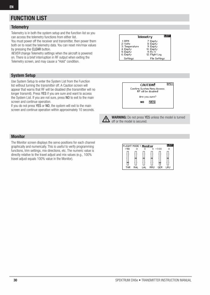
Telemetry
Telemetry is in both the system setup and the function list so you can access the telemetry functions from either list.You must power off the receiver and transmitter, then power them both on to reset the telemetry data. You can reset min/max values by pressing the CLEAR button.NEVER change Telemetry settings when the aircraft is powered on. There is a brief interruption in RF output when exiting the Telemetry screen, and may cause a “Hold” condition.
System Setup
Use System Setup to enter the System List from the Function list without turning the transmitter off. A Caution screen will appear that warns that RF will be disabled (the transmitter will no longer transmit). Press YES if you are sure and want to access the System List. If you are not sure, press NO to exit to the main screen and continue operation.If you do not press YES or NO, the system will exit to the main screen and continue operation within approximately 10 seconds.
WARNING: Do not press YES unless the model is turned off or the model is secured.
Monitor
The Monitor screen displays the servo positions for each channel graphically and numerically. This is useful to verify programming functions, trim settings, mix directions, etc. The numeric value is directly relative to the travel adjust and mix values (e.g., 100% travel adjust equals 100% value in the Monitor).

31SPEKTRUM DX6e • TRANSMITTER INSTRUCTION MANUAL
EN
Aircraft Type
Use the Aircraft Type Screen to select wing and tail types to match your airplane model. Diagrams and setup names show on the transmitter screen to show the available setups.
Refer to spektrumrc.com for more information about new DX6e Spektrum AirWare software updates to support these options.
Select wing and tail types before doing any other programming.
* Selection of multiple ailerons activates the Differential menu option.** “V-Tail A” and “V-Tail B” function as internal servo reversing. If V-Tail A does not work correctly with your aircraft, try V-Tail B.
Wing• Normal • Dual Aileron*• Flaperon*• 1 Aileron 1 Flap*• 2 Ailerons 1 Flap*• Elevon*• Elevon B*
Tail • Normal• V-Tail A**• V-Tail B**• Dual Elevator• Dual Rudder• Dual Rud/Ele
Acro Model Type
NOTICE: Refer to your airplane manual for recommended control throws.
CAUTION: Always do a Control Test of your model with the transmitter after programming to make sure your model responds as desired.
ACRO (AIRPLANE)
A AUX1 servo port (left aileron)B AILE servo port (right aileron)C ELEV servo port (left V-tail)D RUDD servo port (right V-tail)E AILE servo port (left aileron)F ELEV servo port (right aileron)A B
Dual Aileron WingType Connection
FE
Elevon Wing TypeConnection
DC
V-Tail TypeConnection
Recommended Servo Connections
Icon
To change the Aircraft Icon:1. In the Aircraft Type Screen, select NEXT at the bottom right of
the screen. This will access the Aircraft Options screen. 2. Scroll to the image and click once. Roll the scroll wheel left or
right for optional images.3. Click on the image you wish to select.

32 SPEKTRUM DX6e • TRANSMITTER INSTRUCTION MANUAL
EN
Elevon Servo Control
The possible servo reversing options for a delta wing model are:Tip: If you test all servo reversing options and the control surfaces do not move in the correct direction, change the Elevon wing type in the System Setup list from Elevon-tto Elevon-B.
Aileron Elevator
Normal Reverse
Normal Normal
Reverse Reverse
Reverse Normal
RightRudder
LeftRudder
UpElevator
DownElevator
LeftAileron
RightAileron
Flap System
The Flap System menu option enables fl ap programming as well as elevator mixing. You must select a fl ap-enabled wing type in Aircraft Type or the Flap System menu does not appear.
To activate the Flap System:
1. Access the System Setup list and select Aircraft Type.
2. Select a fl ap-enabled wing type and exit the System Setup list.
3. Access the Function List from the Main Screen and select Flap System.
4. Select Inhibit and scroll to the switch or lever you wish to use to control the fl ap channel.
5. Assign the Flap travel values and any desired Elevator mixing.
6. Select a Flap speed, if desired. Norm (default) does not have a delay. Flap speed options range from 0.1s to 30 seconds.
ACRO Mixing
Rudder to Aileron/ElevatorRudder to Aileron/Elevator mixing corrects coupling in knife edge fl ight.
• Add Elevator mixing if the aircraft pitches toward the landing gear or canopy
• Add Aileron mixing if the aircraft rolls in knife edge fl ight
Aileron to RudderUse Aileron to Rudder mixing to overcome adverse yaw characteristics with certain types of aircraft (such as high-wing aircraft).
Elevator to FlapElevator to Flap mixing enables Flap movement when the Elevator stick moves. Use Elevator to Flap mixing to add the spoileron function to 3D aerobatic aircraft. This mix is available when a fl ap or dual aileron wing type is selected.
ACRO (AIRPLANE)

33SPEKTRUM DX6e • TRANSMITTER INSTRUCTION MANUAL
EN
Swash Type
The Swash Type menu option assigns the swash type for your particular helicopter model.
Select the Swash Type before completing any programming in the Function List. The Swash Type will affect menu options in the Function List.
Collective Type
The collective type is used to turn on “Pull” collective for reversed collective. Available settings are Normal and Reverse. Press NEXT from the Swashplate Type screen to access the Collective Type screen. The Collective Type allows the throttle/pitch stick to operate in reverse and ensures trims, curves and all other functions that are to work in reverse function properly.
Pitch Curve
This function supports adjustment of collective pitch in 5 fl ight modes.
To adjust the Pitch Curve:1. Select the Pitch Curve you wish to edit (N, 1 or 2).
2. Scroll right to select the points on the curve and edit the respective values.
3. Press the BACK button to save the Pitch Curves and return to the Function List.
Heli Model Type
NOTICE: Refer to your helicopter, gyro and governor manuals for programming recommendations.
CAUTION: Always do a Control Test of your model with the transmitter after programming changes to make sure your model responds as desired.
HELI (HELICOPTER)
To change the Helicopter Icon:From the Collective Type Screen, select NEXT at the bottom right of the screen. This will access the Heli image screen. Scroll to the icon and click once. Roll the scroll wheel left or right for optional icons.

34 SPEKTRUM DX6e • TRANSMITTER INSTRUCTION MANUAL
EN
Swashplate
The Swashplate menu option enables you to adjust the following:• Swashplate Mix
• Exponential
• E-Ring
• Elevator Compensation
Use positive or negative Swashplate mix values as needed for correct direction response of the helicopter.Before making adjustments to the Swashplate mix, make sure the throttle/collective pitch input moves the entire swashplate up or down. If the servos are not moving in the same direction, reverse them as necessary in the Servo Setup menu option.
When the entire swashplate moves up or down:
1. Adjust the mix value for the Aileron and Elevator channels. If the servos do not move in the correct direction, change the direction of the mix—for example, a positive value instead of a negative value.
2. Adjust the mix value for the Pitch. If the swashplate does not move in the correct direction, change the direction of the value (negative instead of positive).
Always enable Expo when using a standard rotating-arm servo.The Expo delivers linear movement of the swashplate from a standard rotary servo. When Expo is inhibited, the arm on a rotary servo moves on a curved path with decreased swashplate movement at the extremes of the servo arm travel.
NOTICE: Do not enable Expo when using a linear servo.
Electronic E-RingThis feature prevents over driving servos by limiting servo travel if the sum of your cyclic and pitch inputs exceeds servo limits.
Gyro
The Gyro menu option enables you to assign a gyro gain value
to an independent switch or a Flight Mode. Assign the receiver
channel connected to the gyro, then assign the switch for gyro
options. You can also assign values to available switch positions
(from 1 to 4 rates are available, depending on the switch
assigned). Make sure the gyro operates correctly and
compensates in the correct direction.
Mixing
Cyclic to ThrottleCyclic to Throttle mix prevents rpm loss when aileron, elevator or rudder inputs are given. This mix advances the throttle position with cyclic or rudder control to maintain rpm. At full throttle, Cyclic to Throttle mixing prevents the throttle from over driving the servo.
IMPORTANT: Do not use Cyclic to Throttle mix when using a governor.
To verify that the Cyclic to Throttle mix is working properly and in the correct direction, move the fl ight mode switch to one of the active positions. Move the programmed cyclic or rudder channel, noting the throttle position. The throttle position should increase.
If the throttle decreases, then the opposite value (positive vs. negative) is needed.
SwashplateThe Swashplate Mix typically corrects swashplate timing issues by mixing Aileron to Elevator and Elevator to Aileron. When adjusted correctly, the Swashplate causes the helicopter to roll and pitch accurately with minimal interaction.
HELI (HELICOPTER)

35SPEKTRUM DX6e • TRANSMITTER INSTRUCTION MANUAL
EN
Sailplane Type
Use the Sailplane Type Screen to select wing and tail types to match your sailplane model. Diagrams and setup names show on the transmitter screen to show the available setups.
Refer to spektrumrc.com for more information about new DX6e Spektrum AirWare updates to support these options.
* Selection of multiple ailerons activates the Differential menu option.** “V-Tail A” and “V-Tail B” function as internal servo reversing. If V-Tail A does not work correctly with your aircraft, try V-Tail B.
Camber Preset
Camber Preset is only available when 2 aileron wing type is selected in Sailplane Type. The Camber Preset function enables you to program the ailerons, fl aps, wing tips and elevator for a specifi c position in each Flight Mode.
If fl ight modes are not active, only one preset position is available and it is always active.
The Camber Preset Speed enables the control surfaces to transition over a period of time, up to 30 seconds, when you change fl ight modes.
Move the fl ight mode switch to the desired position to change the Camber Preset values.
Wing• 1 Servo• 2 Aileron*• 2 Aileron 1 Flap*• 2 Aileron 2 Flap*
Tail• Normal• V-Tail A**• V-Tail B**
Motor• Inhibit• Assign to a
Switch (optional)
Sailplane Model Type
NOTICE: Refer to your sailplane manual for recommended control throws.
CAUTION: Always do a Control Test of your model with the transmitter after programming to make sure your model responds as desired.
Camber System
Camber System is only available when 2 aileron wing type is selected in Sailplane Type. The Camber System allows in-fl ight camber adjustment and is also used as the braking system, often referred to as Crow or Butterfl y. The Camber System enables you to assign the Camber System to a different switch in each fl ight mode.
SAIL (SAILPLANE)
Sailplane IconIn the Sailplane Type Screen, select NEXT at the bottom right of the screen. This will access the Sailplane Image screen. Click once on the image and roll the scroll wheel left or right to for optional images.

36 SPEKTRUM DX6e • TRANSMITTER INSTRUCTION MANUAL
EN
Aileron to RudderThe Aileron to Rudder mix is commonly used for coordinated turns. When active, as aileron is applied the rudder moves in the same direction as the turn (right aileron input results in right rudder output). If you assign the fl ight mode to a switch, a Sub Switch option allows you to assign an additional switch to activate up to 3 Aileron to Rudder mixes for that fl ight mode.
Aileron to Flap
The Aileron to Flap mix allows the entire trailing edge of the wing
(aileron and fl ap) to operate as ailerons. When active, as aileron is
applied the fl aps also move. Always program the fl aps to move in
the same direction as the turn (so that right aileron is equivalent to
fl aps moving as right ailerons).
Elevator to FlapElevator to Flap mix creates additional lift, allowing a tighter turn. The entire trailing edge of the wing (aileron and fl ap) operates as fl aps (camber increase) when you apply elevator. An offset is provided, which is typically used for Snap Flaps. With Snap Flap, no Elevator to Flap mix occurs until the offset value is reached. Typically, this offset is at 70% up elevator so that beyond 70% the down fl ap mix comes in, providing additional lift for more aggressive turning (for tight thermals or racing turns).
Flap to ElevatorFlap to Elevator mix prevents pitch up tendency that occurs when you apply Crow or Butterfl y. This mix is typically used only with the Camber System. The Flap to Elevator mix operates as a curve so that the elevator moves down the most during the fi rst 20% of fl ap deployment, decreases over the next 40%, then remains the same from 60 to 100% of fl ap travel.
For sailplanes with ailerons/tips/fl aps, make sure an appropriate Sailplane Type is selected so that tips appear in the transmitter as RAIL and LAIL. Decrease or increase travel on the tip ailerons by creating an AIL > RAIL mix.
SAIL Mixing
For each of these mixes, you can program each fl ight mode with different mix values or at 0% if no mix is desired for that specifi c fl ight mode. Programming values include independent control of the direction and amount a slave surface moves in relationship to the master surface.
V-Tail Differential
The V-Tail Differential screen enables you to increase or decrease the amount of differential between control surface throws. Positive Differential values decrease the amount of “down” travel without affecting the “up” travel on the opposite control surface.Negative Differential values decrease the amount of “up” travel without affecting the amount of “down” travel on the opposite control surface.The V-Tail Differential menu option only appears when V-Tail A or V-Tail B is active in Aircraft Type.
To adjust the V-Tail Differential:
1. Scroll to Switch and press the scroll wheel. Scroll right to select On (Differential is always on) or assign the differential to a switch position.
2. Press the scroll wheel a second time to save the selection.
3. Scroll to Diff: and press the scroll wheel once to change the value.
4. Press the scroll wheel again to save the selection.
SAIL (SAILPLANE)

37SPEKTRUM DX6e • TRANSMITTER INSTRUCTION MANUAL
EN
The Aircraft Options menu allows you to select a camera gimbal axis. Select None, 1–Axis, 2–Axis or 3–Axis from the Camera Options box.
The model icon can be changed by selecting the icon and scrolling left or right to select.
By default Trims are setup for F Mode.
F Mode trim type enables you to save trim values for individual fl ight modes if you fi nd, for example, the aircraft requires Roll trim in Flight Mode 1 but not in Flight Mode 2.
By default switch B is assigned 3 Flight Modes. You can assign up to fi ve fl ight modes using any combination of up to two switches.
Channel AssignScroll and Select Channel to assign channel inputs and outputs for each Flight Mode. Each channel can be assigned any switch on the transmitter including but not limited to trim switches, gimbals and the Clear/Back buttons.
Example: Assign Flight Mode 1 to be your primary fl ight mode where your gimbals control primary fl ight axis. Switching to Flight Mode 2, you can have the gimbals control the camera axis and the trim buttons control primary fl ight axis.
Tip: You can also access the Channel Assign from the Channel Assign Menu in System Setup.
Multirotor Model Type
NOTICE: Refer to your multirotor manual for programming recommendations.
CAUTION: Always do a Control Test of your model with the transmitter after programming to make sure your model responds as desired.
MULTI (MULTIROTOR)
F-Mode Setup
Trim Setup
Multirotor ImageIn the Aircraft Options Screen, roll to the image. Click once on the image and roll the roller left or right for optional images.

38 SPEKTRUM DX6e • TRANSMITTER INSTRUCTION MANUAL
EN
Dual Rates and Exponential are available on the PIT, ROL and YAW channels.
To adjust the Dual Rate and Exponential:1. Scroll to the channel and press the scroll wheel once. Scroll
left or right to select the channel you wish to change and press the scroll wheel again to save the selection.
2. Scroll to Switch and press the scroll wheel to select. Move the switch you want to assign to D/R.
3. Scroll to dual rate and press the scroll wheel. Scroll left or right to change the value and press the scroll wheel again to save the selection.
Exponential affects control response sensitivity around center but has no affect on overall travel. Positive exponential decreases the sensitivity around the center of gimbal movement.
The Motor Cut menu option enables you to assign a switch position to stop the motor. Motor Cut activates regardless of Flight Mode.When you activate Motor Cut, the ALT channel moves to the pre-programmed position (normally Off). You may need to use a negative value to move the ALT channel to the off position.
CAUTION: Always test the model after making adjustments to make sure the model responds to controls
as desired.
You can use the Motor Curve menu option to optimize the throttle response. A maximum of 7 points are available on the throttle curve.
To add points to a Motor Curve:
1. Move the throttle stick to the position where you wish to add the new point.
2. Scroll to Add Pt. and press the scroll wheel to add the point.
To remove points from a Motor Curve:
1. Move the Motor stick until the cursor is near the point you wish to remove.
2. Scroll to Remove Pt. and press the scroll wheel once to remove the point.
If you program multiple throttle curves and you wish to edit one of the curves, that curve must be active in the Motor Curve screen before you can make any changes.
MULTI (MULTIROTOR)
D/R & Exponential
Motor Cut
Motor Curve

39SPEKTRUM DX6e • TRANSMITTER INSTRUCTION MANUAL
EN
PHYSICAL TRANSMITTER ADJUSTMENTS
Ratcheted Throttle – Smooth Throttle Adjustment
Ratchet:
1. Locate the Throttle Strap adjustment screws on both gimbals. The ratchet set screw engages a serrated section on the gimbal for a ratcheted throttle, while the tension set screw engages a strap for smooth tension on the gimbal.
2. To engage the throttle ratchet turn the ratchet set screw clockwise until the ratchet engages.
3. To disengage the throttle ratchet turn the screw counter clockwise until the gimbal moves freely.
Smooth Tension:
1. To engage the throttle tension, turn the Tension set screw clockwise until the Tension engages.
2. To disengage the throttle Tension turn the screw counter clockwise until the gimbal moves freely.
Adjust Stick TensionTurn the screws clockwise a small amount using a small Phillips
screwdriver to tighten the stick tension and counter clockwise to
loosen.
NOTICE: Always do a test of stick tension while turning these screws to ensure stick tension is not too loose or too tight. Tightening a screw too much can damage a spring. Loosening a screw too much can let a spring fall off and cause short-circuit in the transmitter.
Control Stick Length Adjustment 1. Using a 2mm Allen wrench, turn the setscrew in the stick
counterclockwise to loosen it.
2. Make the stick shorter by turning it clockwise or longer by turn ing it counterclockwise.
3. After adjustment of stick length, tighten the setscrew.
The DX6e has all the physical transmitter adjustments located around the gimbal face of each gimbal. This arrangement allows for quick and easy adjustments with out taking the back cover off or removing any plugs to access adjustment screws.
Available adjustments:
Change the Throttle Ratchet
Change the Throttle Tension
Adjust stick tension
Tension
Tension
Ratchet
Ratchet
Vertical Tension
Vertical Tension
Horizontal Tension
Horizontal Tension

40 SPEKTRUM DX6e • TRANSMITTER INSTRUCTION MANUAL
EN
PHYSICAL TRANSMITTER ADJUSTMENTS
Mode Change Slider
The DX6e has a unique Slider located on the back of the transmitter that allows for simple mode changes. The slider can also be used to change each mode into a “quadcopter mode”. This mode snaps both stick to the center position.
Simply open the protective slider door and move the slider to the desired position. All changes happen automatically inside the transmitter.
If you are changing from mode 2(4) to mode 1(3) you must fi rst go into the System Settings and change the mode in the programming.
Programming Conversion
1. Access the System Settings menu from the Setup List and select the desired Mode.
2. Exit the System Settings menu to save the selection.
Calibrating
After changing modes, the transmitter will need to be calibrated. See the calibration section in System Settings.
Mode 2,4
Mode 2,4
Mode 2,4Quadcopter
Mode 2,4Quadcopter
Mode 1,3
Mode 1,3Quadcopter
Mode Slider
Slider Door
Saftey plug
The Saftey plug is installed in the transmitter to ensure the mode switch can not be accidentally moved when in the normal throttle mode (non-centered) positions..
To remove the plug:
1. Grasp the plug by the raised rib and pull straight out.
Tip: A small screw driver can be used to gently pry the plug out.
2. Once the mode has been changed, reinstall the saftey plug.

41SPEKTRUM DX6e • TRANSMITTER INSTRUCTION MANUAL
EN
Problem Possible Cause Solution
Aircraft will not Bind (during binding) to transmitter
Transmitter too near aircraft during binding process
Move powered transmitter a few feet from aircraft, disconnect and reconnect fl ight battery to aircraft
Aircraft or transmitter is too close to large metal object
Move the aircraft or transmitter away from the large metal object
The bind plug is not installed correctly in the bind port
Install bind plug in bind port and bind the aircraft to the transmitter
Flight battery/Transmitter battery charge is too low
Replace/recharge batteries
Aircraft will not link (after binding) to transmitter
Transmitter too near aircraft during linking process
Move powered transmitter a few feet from aircraft, disconnect and reconnect fl ight battery to aircraft
Aircraft or transmitter is too close to large metal object
Move the aircraft or transmitter away from the large metal object
Bind plug left installed in bind portRebind transmitter to the aircraft and remove the bind plug before cycling power
Aircraft bound to different model memory (ModelMatch™ radios only)
Select correct model memory on transmitter
Flight battery/Transmitter battery charge is too low
Replace/recharge batteries
Transmitter may have been bound using different DSM protocol
Bind aircraft to transmitter
Damaged remote receiver or receiver extension. Required remote receiver is not connected
The receiver goes into failsafe mode a short distance away from the transmitter
Check the receiver antenna to be sure it is not cut or damaged
Replace or contact Horizon Product Support
Main and remote receivers too near each otherInstall main and remote receivers at least 2 inches (51mm) apart
Receiver quits responding during operation
Low battery voltage Completely recharge fl ight battery
Loose or damaged wires or connectors between battery and receiver
Do a check of the wires and connection between battery and receiver. Repair or replace wires and/or connectors
Receiver loses its bind Bind button pressed before transmitter powered on Rebind by performing binding instructions
Receiver slowly blinking at landing (DSM2 Only)
Loss of power to the receiver during flight Check battery voltage
System powered on and connected, then receiver powered off without powering off transmitter
Power off transmitter when receiver is powered off
Flight log registers undesirable number of fades, losses or holds or aircraft responds irregularly to controls
Poor signal receptionReposition remote receivers for improved RF signal path diversity
Electronic feedbackCheck for and stop feedback from servos or motor systems to the ESC or receiver
Low power
Check aircraft power draw and increase battery power or decrease power demand by installed systems. Ensure all aircraft batteries are fully charged. Ensure the installed BEC for an electric aircraft is adequate for the power demand
TROUBLESHOOTING GUIDE

42 SPEKTRUM DX6e • TRANSMITTER INSTRUCTION MANUAL
EN
1-YEAR LIMITED WARRANTYWhat this Warranty CoversHorizon Hobby, LLC, (Horizon) warrants to the original purchaser that the product purchased (the “Product”) will be free from defects in materials and workmanship for a period of 1 year from the date of purchase.
What is Not CoveredThis warranty is not transferable and does not cover (i) cosmetic damage, (ii) damage due to acts of God, accident, misuse, abuse, negligence, commercial use, or due to improper use, installation, operation or maintenance, (iii) modifi cation of or to any part of the Product, (iv) attempted service by anyone other than a Horizon Hobby authorized service center, (v) Product not purchased from an authorized Horizon dealer, (vi) Product not compliant with applicable technical regulations or (vii) use that violates any applicable laws, rules, or regulations. OTHER THAN THE EXPRESS WARRANTY ABOVE, HORIZON MAKES NO OTHER WARRANTY OR REPRESENTATION, AND HEREBY DISCLAIMS ANY AND ALL IMPLIED WARRANTIES, INCLUDING, WITHOUT LIMITATION, THE IMPLIED WARRANTIES OF NON-INFRINGEMENT, MERCHANTABILITY AND FITNESS FOR A PARTICULAR PURPOSE. THE PURCHASER ACKNOWLEDGES THAT THEY ALONE HAVE DETERMINED THAT THE PRODUCT WILL SUITABLY MEET THE REQUIREMENTS OF THE PURCHASER’S INTENDED USE.
Purchaser’s RemedyHorizon’s sole obligation and purchaser’s sole and exclusive remedy shall be that Horizon will, at its option, either (i) service, or (ii) replace, any Product determined by Horizon to be defective. Horizon reserves the right to inspect any and all Product(s) involved in a warranty claim. Service or replacement decisions are at the sole discretion of Horizon. Proof of purchase is required for all warranty claims. SERVICE OR REPLACEMENT AS PROVIDED UNDER THIS WARRANTY IS THE PURCHASER’S SOLE AND EXCLUSIVE REMEDY.
Limitation of LiabilityHORIZON SHALL NOT BE LIABLE FOR SPECIAL, INDIRECT, INCIDENTAL OR CONSEQUENTIAL DAMAGES, LOSS OF PROFITS OR PRODUCTION OR COMMERCIAL LOSS IN ANY WAY, REGARDLESS OF WHETHER SUCH CLAIM IS BASED IN CONTRACT, WARRANTY, TORT, NEGLIGENCE, STRICT LIABILITY OR ANY OTHER THEORY OF LIABILITY, EVEN IF HORIZON HAS BEEN ADVISED OF THE POSSIBILITY OF SUCH DAMAGES. Further, in no event shall the liability of Horizon exceed the individual price of the Product on which liability is asserted. As Horizon has no control over use, setup, fi nal assembly, modifi cation or misuse, no liability shall be assumed nor accepted for any resulting damage or injury. By the act of use, setup or assembly, the user accepts all resulting liability. If you as the purchaser or user are not prepared to accept the liability associated with the use of the Product, purchaser is advised to return the Product immediately in new and unused condition to the place of purchase.
LawThese terms are governed by Illinois law (without regard to confl ict of law principals). This warranty gives you specifi c legal rights, and you may also have other rights which vary from state to state. Horizon reserves the right to change or modify this warranty at any time without notice.
WARRANTY SERVICES
Questions, Assistance, and ServicesYour local hobby store and/or place of purchase cannot provide warranty support or service. Once assembly, setup or use of the Product has been started, you must contact your local distributor or Horizon directly. This will enable Horizon to better answer your
questions and service you in the event that you may need any assistance. For questions or assistance, please visit our website at www.horizonhobby.com, submit a Product Support Inquiry, or call the toll free telephone number referenced in the Warranty and Service Contact Information section to speak with a Product Support representative.
Inspection or ServicesIf this Product needs to be inspected or serviced and is compliant in the country you live and use the Product in, please use the Horizon Online Service Request submission process found on our website or call Horizon to obtain a Return Merchandise Authorization (RMA) number. Pack the Product securely using a shipping carton. Please note that original boxes may be included, but are not designed to withstand the rigors of shipping without additional protection. Ship via a carrier that provides tracking and insurance for lost or damaged parcels, as Horizon is not responsible for merchandise until it arrives and is accepted at our facility. An Online Service Request is available at http://www.horizonhobby.com/content/_service-center_render-service-center. If you do not have internet access, please contact Horizon Product Support to obtain a RMA number along with instructions for submitting your product for service. When calling Horizon, you will be asked to provide your complete name, street address, email address and phone number where you can be reached during business hours. When sending product into Horizon, please include your RMA number, a list of the included items, and a brief summary of the problem. A copy of your original sales receipt must be included for warranty consideration. Be sure your name, address, and RMA number are clearly written on the outside of the shipping carton.
NOTICE: Do not ship LiPo batteries to Horizon. If you have any issue with a LiPo battery, please contact the appropriate Horizon Product Support offi ce.
Warranty RequirementsFor Warranty consideration, you must include your original sales receipt verifying the proof-of-purchase date. Provided warranty conditions have been met, your Product will be serviced or replaced free of charge. Service or replacement decisions are at the sole discretion of Horizon.
Non-Warranty Service
Should your service not be covered by warranty, service will be completed and payment will be required without notifi cation or estimate of the expense unless the expense exceeds 50% of the retail purchase cost. By submitting the item for service you are agreeing to payment of the service without notifi cation. Service estimates are available upon request. You must include this request with your item submitted for service. Non-warranty service estimates will be billed a minimum of ½ hour of labor. In addition you will be billed for return freight. Horizon accepts money orders and cashier’s checks, as well as Visa, MasterCard, American Express, and Discover cards. By submitting any item to Horizon for service, you are agreeing to Horizon’s Terms and Conditions found on our website http://www.horizonhobby.com/content/_service-center_render-service-center.
ATTENTION: Horizon service is limited to Product compliant in the country of use and ownership. If received, a non-compliant Product will not be serviced. Further, the sender will be responsible for arranging return shipment of the un-serviced Product, through a carrier of the sender’s choice and at the sender’s expense. Horizon will hold non-compliant Product for a period of 60 days from notifi cation, after which it will be discarded.
10-15

43SPEKTRUM DX6e • TRANSMITTER INSTRUCTION MANUAL
EN
WARRANTY AND SERVICE CONTACT INFORMATION
This device complies with part 15 of the FCC rules. Operation is subject to the following two conditions:
1. This device may not cause harmful interference.
2. This device must accept any interference received, including interference that may cause undesired operation.
CAUTION: Changes or modifi cations not expressly approved by the party responsible for compliance could
void the user’s authority to operate the equipment.
This product contains a radio transmitter with wireless technology which has been tested and found to be compliant with the applicable regulations governing a radio transmitter in the 2.400GHz to 2.4835GHz frequency range.
Supplier’s Declaration of Conformity
DX6e Transmitter Only – SPMR6655 DX6e Transmitter with AR620 – SPM6655
This device complies with part 15 of the FCC Rules. Operation is subject to the following two conditions: (1) This
device may not cause harmful interference, and (2) this device must accept any interference received, including interference that may cause undesired operation.
CAUTION: changes or modifi cations not expressly approved by the party responsible for compliance could
void the user’s authority to operate the equipment.
Note: This equipment has been tested and found to comply with the limits for a Class B digital device, pursuant to part 15 of the FCC Rules. These limits are designed to provide reasonable protection against harmful interference in a residential installation. This equipment generates, uses and can radiate radio frequency energy and, if not installed and used in accordance with the instructions, may cause harmful interference to radio communications. However, there is no guarantee that interference will not occur in a particular installation. If this equipment does cause harmful interference to radio or television reception, which can be determined by turning the equipment off and on, the user is encouraged to try to correct the interference by one or more of the following measures:
• Reorient or relocate the receiving antenna.
• Increase the separation between the equipment and receiver.
• Connect the equipment into an outlet on a circuit different from that to which the receiver is connected.
• Consult the dealer or an experienced radio/TV technician for help.
Horizon Hobby, LLC
4105 Fieldstone Rd.,
Champaign, IL 61822
Email: [email protected]
Web: HorizonHobby.com
FCC INFORMATION
Country of Purchase Horizon Hobby Contact Information Address
United States of
America
Horizon Service Center
(Repairs and Repair Requests)
servicecenter.horizonhobby.com/
RequestForm/
2904 Research Rd
Champaign, Illinois, 61822 USA
Horizon Product Support
(Product Technical Assistance)
877-504-0233
800-338-4639
EUHorizon Technischer Service [email protected] Hanskampring 9
D 22885 Barsbüttel, GermanySales: Horizon Hobby GmbH +49 (0) 4121 2655 100
Contains FCC ID: BRWPLANO1TFCC ID: BRWP68CEVAUR

44 SPEKTRUM DX6e • TRANSMITTER INSTRUCTION MANUAL
EN
COMPLIANCE INFORMATION FOR THE EUROPEAN UNION
This device complies with Industry Canada licence-exempt RSS standard(s). Operation is subject to the following two conditions:
(1) this device may not cause interference, and (2) this device must accept any interference, including interference that may cause undesired operation of the device.
IC INFORMATION
CAN ICES-3 (B)/NMB-3(B)Contains IC: 6157A-PLANO1TIC: 6157A-P68CEVAUR
AMA NATIONAL MODEL AIRCRAFT SAFETY CODEhttp://www.modelaircraft.org/fi les/105.PDF
FAA INFORMATION
Prior to fl ying, contact your local or regional modeling organizations for guidance and familiarize yourself with the current local rules and FAA regulations governing model aviation in your location.More information about model aviation can be found atwww.modelaircraft.org.
The Federal Aviation Administration can be found online atwww.faa.gov.
Instructions for disposal of WEEE by users in the European Union
This product must not be disposed of with other waste. Instead, it is the user’s responsibility to dispose of their waste equipment by handing it over to a designated collections point for the recycling of waste electrical and electronic equipment. The
separate collection and recycling of your waste equipment at the time of disposal will help to conserve natural resources and
ensure that it is recycled in a manner that protects human health and the environment. For more information about where you can drop off your waste equipment for recycling, please contact your local city offi ce, your household waste disposal service or where you purchased the product.
EU Compliance Statement:
Horizon Hobby, LLC hereby declares that this product is in compliance with the essential requirements and other relevant provisions of the RED Directive.
A copy of the EU Declaration of Conformity is available online at:http://www.horizonhobby.com/content/support-render-compliance.

© 2019 Horizon Hobby, LLCDSM, DSM2, DSMX, the DSMX logo, the BNF logo, Spektrum AirWare, ModelMatch, X-Plus, AS3X,
SmartSafe, Hangar 9 and the Horizon Hobby logo are trademarks or registered trademarks of Horizon Hobby, LLC. The Spektrum trademark is used with permission of Bachmann Industries, Inc.
The SD Logo is a trademark of SD-3C, LLCUS 7,391,320. US 8,672,726. Other patents pending.
www.spektrumrc.com
Updated 02/19 • 50468.2 • SPM6655, SPMR6655