Embed Size (px)
Citation preview
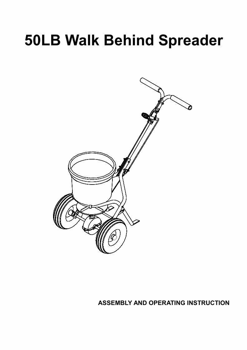
50LB Walk Behind Spreader
ASSEMBLY AND OPERATING INSTRUCTION
2
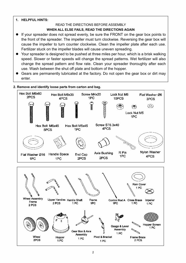
2. Remove and identify loose parts from carton and bag.
1. HELPFUL HINTS: READ THE DIRECTIONS BEFORE ASSEMBLY
WHEN ALL ELSE FAILS, READ THE DIRECTIONS AGAIN If your spreader does not spread evenly, be sure the FRONT on the gear box points to
the front of the spreader. The impeller must turn clockwise. Reversing the gear box will cause the impeller to turn counter clockwise. Clean the impeller plate after each use. Fertilizer stuck on the impeller blades will cause uneven spreading.
Your spreader is designed to be pushed at three miles per hour, which is a brisk walking speed. Slower or faster speeds will change the spread patterns. Wet fertilizer will also change the spread pattern and flow rate. Clean your spreader thoroughly after each use. Wash between the shut off plate and bottom of the hopper.
Gears are permanently lubricated at the factory. Do not open the gear box or dirt may enter.
3
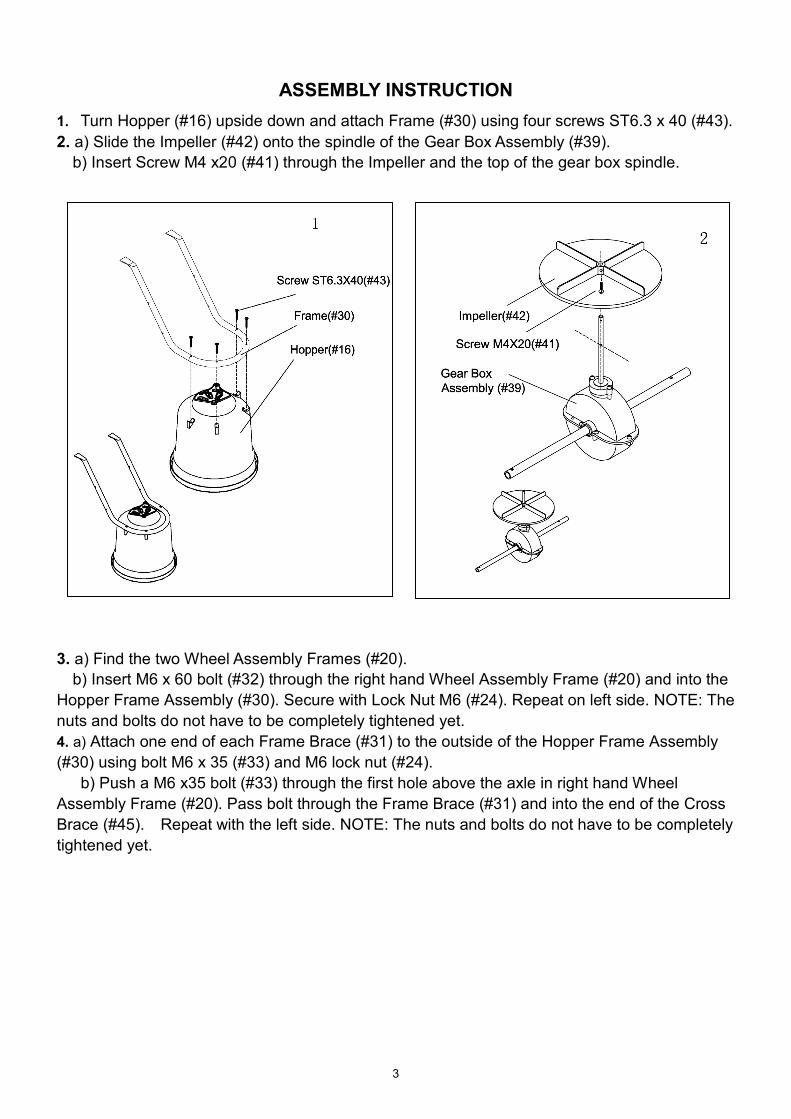
ASSEMBLY INSTRUCTION1. Turn Hopper (#16) upside down and attach Frame (#30) using four screws ST6.3 x 40 (#43). 2. a) Slide the Impeller (#42) onto the spindle of the Gear Box Assembly (#39).
b) Insert Screw M4 x20 (#41) through the Impeller and the top of the gear box spindle.
3. a) Find the two Wheel Assembly Frames (#20).
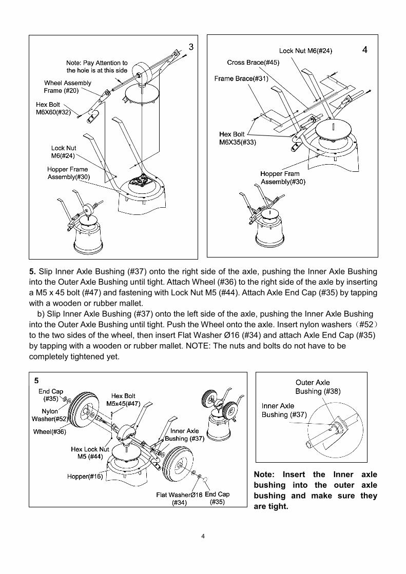
b) Insert M6 x 60 bolt (#32) through the right hand Wheel Assembly Frame (#20) and into the Hopper Frame Assembly (#30). Secure with Lock Nut M6 (#24). Repeat on left side. NOTE: The nuts and bolts do not have to be completely tightened yet. 4. a) Attach one end of each Frame Brace (#31) to the outside of the Hopper Frame Assembly (#30) using bolt M6 x 35 (#33) and M6 lock nut (#24).
b) Push a M6 x35 bolt (#33) through the first hole above the axle in right hand Wheel Assembly Frame (#20). Pass bolt through the Frame Brace (#31) and into the end of the Cross Brace (#45). Repeat with the left side. NOTE: The nuts and bolts do not have to be completely tightened yet.
4
5. Slip Inner Axle Bushing (#37) onto the right side of the axle, pushing the Inner Axle Bushing into the Outer Axle Bushing until tight. Attach Wheel (#36) to the right side of the axle by inserting a M5 x 45 bolt (#47) and fastening with Lock Nut M5 (#44). Attach Axle End Cap (#35) by tapping with a wooden or rubber mallet.
b) Slip Inner Axle Bushing (#37) onto the left side of the axle, pushing the Inner Axle Bushing into the Outer Axle Bushing until tight. Push the Wheel onto the axle. Insert nylon washers(#52)to the two sides of the wheel, then insert Flat Washer Ø16 (#34) and attach Axle End Cap (#35) by tapping with a wooden or rubber mallet. NOTE: The nuts and bolts do not have to be completely tightened yet.
Note: Insert the Inner axle bushing into the outer axle bushing and make sure they are tight.
5
5
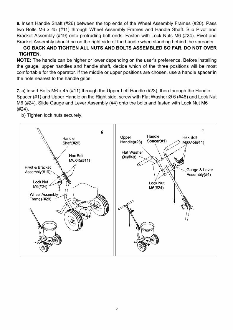
6. Insert Handle Shaft (#26) between the top ends of the Wheel Assembly Frames (#20). Pass two Bolts M6 x 45 (#11) through Wheel Assembly Frames and Handle Shaft. Slip Pivot and Bracket Assembly (#19) onto protruding bolt ends. Fasten with Lock Nuts M6 (#24). Pivot and Bracket Assembly should be on the right side of the handle when standing behind the spreader. GO BACK AND TIGHTEN ALL NUTS AND BOLTS ASSEMBLED SO FAR. DO NOT OVER TIGHTEN.
NOTE: The handle can be higher or lower depending on the user’s preference. Before installing the gauge, upper handles and handle shaft, decide which of the three positions will be most comfortable for the operator. If the middle or upper positions are chosen, use a handle spacer in the hole nearest to the handle grips. 7. a) Insert Bolts M6 x 45 (#11) through the Upper Left Handle (#23), then through the Handle Spacer (#1) and Upper Handle on the Right side, screw with Flat Washer Ø 6 (#48) and Lock Nut M6 (#24). Slide Gauge and Lever Assembly (#4) onto the bolts and fasten with Lock Nut M6 (#24).
b) Tighten lock nuts securely.
6
6
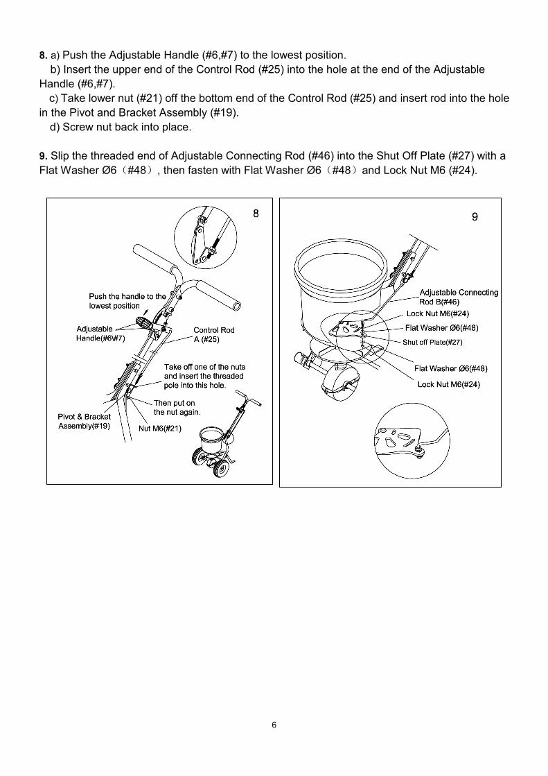
8. a) Push the Adjustable Handle (#6,#7) to the lowest position. b) Insert the upper end of the Control Rod (#25) into the hole at the end of the Adjustable
Handle (#6,#7). c) Take lower nut (#21) off the bottom end of the Control Rod (#25) and insert rod into the hole
in the Pivot and Bracket Assembly (#19). d) Screw nut back into place.
9. Slip the threaded end of Adjustable Connecting Rod (#46) into the Shut Off Plate (#27) with a Flat Washer Ø6(#48), then fasten with Flat Washer Ø6(#48)and Lock Nut M6 (#24).
7
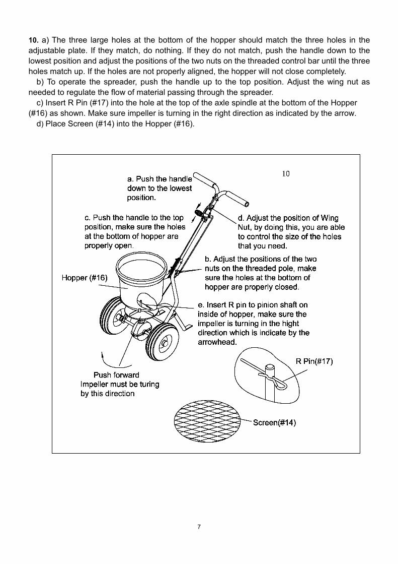
10. a) The three large holes at the bottom of the hopper should match the three holes in the adjustable plate. If they match, do nothing. If they do not match, push the handle down to the lowest position and adjust the positions of the two nuts on the threaded control bar until the three holes match up. If the holes are not properly aligned, the hopper will not close completely.
b) To operate the spreader, push the handle up to the top position. Adjust the wing nut as needed to regulate the flow of material passing through the spreader.
c) Insert R Pin (#17) into the hole at the top of the axle spindle at the bottom of the Hopper (#16) as shown. Make sure impeller is turning in the right direction as indicated by the arrow.
d) Place Screen (#14) into the Hopper (#16).
8
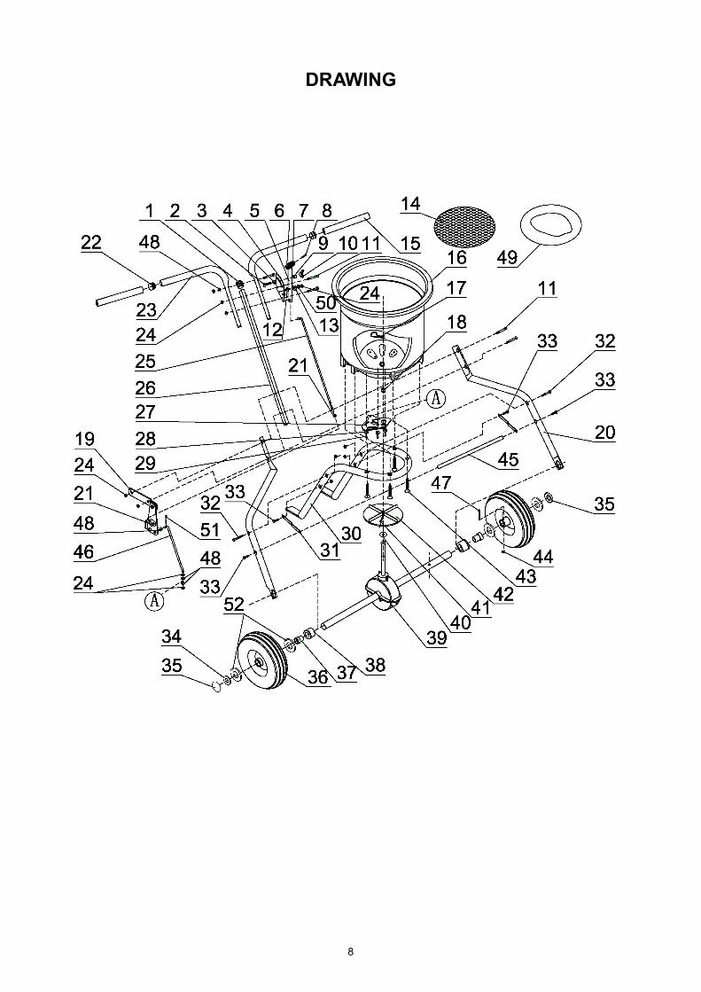
DRAWING
9
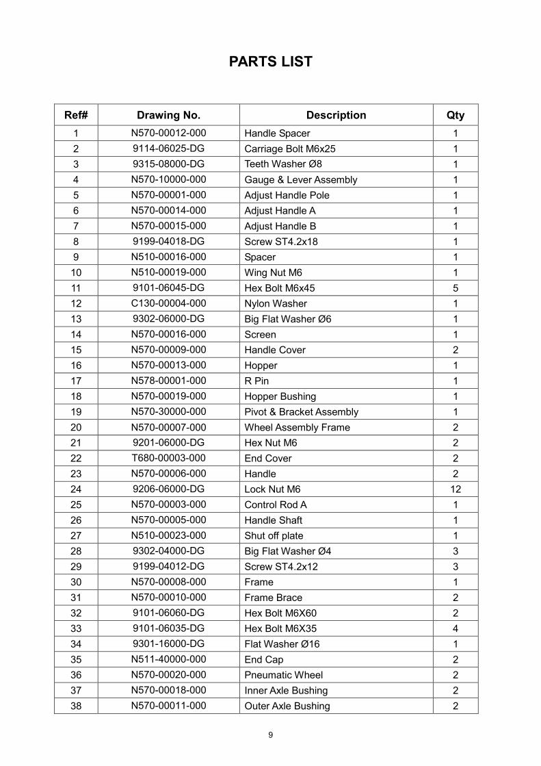
PARTS LIST
Ref# Drawing No. Description Qty
1 N570-00012-000 Handle Spacer 1 2 9114-06025-DG Carriage Bolt M6x25 1 3 9315-08000-DG Teeth Washer Ø8
1
4 N570-10000-000 Gauge & Lever Assembly 1 5 N570-00001-000 Adjust Handle Pole 1 6 N570-00014-000
Adjust Handle A 1
7 N570-00015-000 Adjust Handle B 1 8 9199-04018-DG
Screw ST4.2x18 1
9 N510-00016-000
Spacer 1 10 N510-00019-000 Wing Nut M6 1 11 9101-06045-DG Hex Bolt M6x45 5 12 C130-00004-000 Nylon Washer 1 13 9302-06000-DG Big Flat Washer Ø6 1 14 N570-00016-000 Screen 1 15 N570-00009-000 Handle Cover 2 16 N570-00013-000 Hopper 1 17 N578-00001-000 R Pin 1 18 N570-00019-000 Hopper Bushing 1 19 N570-30000-000 Pivot & Bracket Assembly 1 20 N570-00007-000 Wheel Assembly Frame 2 21 9201-06000-DG Hex Nut M6 2 22 T680-00003-000 End Cover 2 23 N570-00006-000
Handle 2
24 9206-06000-DG Lock Nut M6 12 25 N570-00003-000 Control Rod A 1 26 N570-00005-000 Handle Shaft 1 27 N510-00023-000 Shut off plate 1 28 9302-04000-DG Big Flat Washer Ø4 3 29 9199-04012-DG Screw ST4.2x12 3 30 N570-00008-000 Frame 1 31 N570-00010-000 Frame Brace 2 32 9101-06060-DG Hex Bolt M6X60 2 33 9101-06035-DG Hex Bolt M6X35 4 34 9301-16000-DG Flat Washer Ø16 1 35 N511-40000-000 End Cap 2 36 N570-00020-000 Pneumatic Wheel 2 37 N570-00018-000 Inner Axle Bushing 2 38 N570-00011-000 Outer Axle Bushing 2

10
Ref# Drawing No. Description Qty 39 N578-01000-000 Gear Box & Axle Assemble 1 40 N570-00002-000 Thin Washer 1 41 9199-04020-DG Screw M4x20 1 42 N510-00003-000 Impeller 1 43 9199-06040-DG Screw ST6.3X40 4 44 9206-05000-DG Hex Lock Nut M5 1 45 N570-00021-000 Cross Brace 1 46 N570-00004-000 Adjust Connect Rod B 1 47 9101-05045-DG Hex Bolt M5X45 1 48 9301-06000-DG Flat Washer Ø6 3 49 N570-00022-000 Rain Cover 1 50 9306-06000-DG Lock Washer Ø6 1 51 9404-02010-DG Cotter Pin Ø2x10 1 52 N570-00027 Nylon Washer 4
11
USING YOUR SPREADER 1. Determine approximate square footage of area to be covered and estimate amount of
material required. 2. Before filling the hopper, make sure the flow control arm is in the off position and the closure
plate is shut. 3. Break up any lumpy fertilizer as you fill the hopper. 4. Set the adjustable stop with the flow control arm still in the off position. Refer to the
application chart on this page and to the instructions on the fertilizer bag to select the proper flow rate setting.
5. The application chart is calculated for light to heavy application at a vehicle speed of 3 mph, or 100ft. in 23seconds. A variation in speed will require an adjustment of the flow rate to maintain the same coverage. The faster you drive, the wider the broadcast width.
6. Make sure the drive pin is in stalled in the axle before starting the spreader. 7. Always start the spreader in motion before opening closure plate. 8. Always shut the closure plate before turning or stopping the spreader. 9. If fertilizer is accidentally deposited too heavily in a small area, soak the area thoroughly with
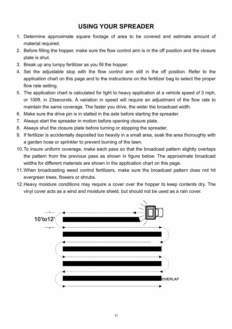
a garden hose or sprinkler to prevent burning of the lawn. 10. To insure uniform coverage, make each pass so that the broadcast pattern slightly overlaps
the pattern from the previous pass as shown in figure below. The approximate broadcast widths for different materials are shown in the application chart on this page.
11. When broadcasting weed control fertilizers, make sure the broadcast pattern does not hit evergreen trees, flowers or shrubs.
12. Heavy moisture conditions may require a cover over the hopper to keep contents dry. The vinyl cover acts as a wind and moisture shield, but should not be used as a rain cover.