Embed Size (px)
DESCRIPTION
Manual de entrenamiento para pantallas HITACHI 50VS810 y varios modelos
Citation preview

CONTENTS... 2004 Models LCD Projection Television Information
INSTRUCTOR… Alvie Rodgers C.E.T. (Chamblee, GA.)
Nov 2004 (ver b) Training Materials Prepared by: ALVIE RODGERS C.E.T.
MODEL CHASSIS
42V710 LC47K 50V710 LC47 60V710 LC47B 50V715 LC47 60V715 LC47B 50VS810 LC48 60VS810 LC48B 70VS810 LC48B 50VX915 LC49 60VX915 LC49B 70VX915 LC49B
32HDL51 PCL1 Backlit LCD
50-60-70VS810-VX915 LCD-PROJECTION
TRAINING 2004
MODEL RELEASE LCD PROJECTION
TELEVISION

2
3
•Chassis Assembly
•Optical Engine Assembly
•Top Assembly
LC-48 - 50VS810This Document contains information related to the
Disassembly Procedures for;
4
Chassis Assembly
•Power PWB
•Digital PWB
•HDMI PWB
•Tuner PWB
LC-48 - 50VS810
Disassembly Procedures
3
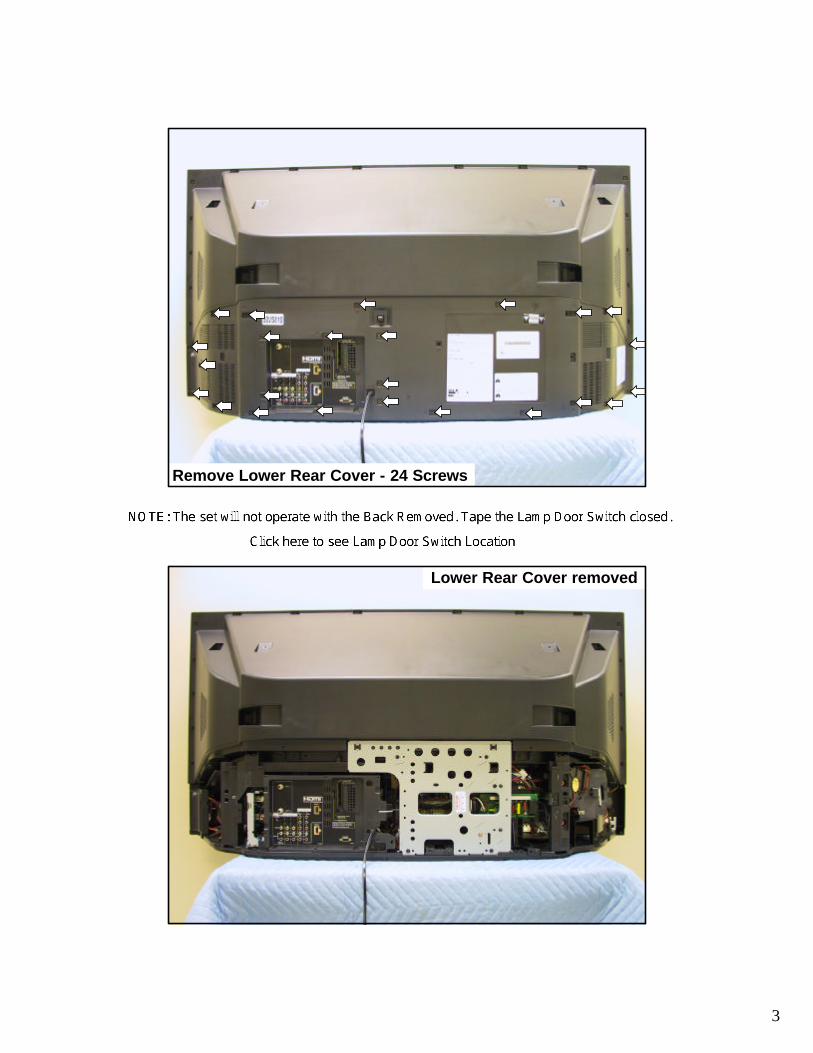
Remove Lower Rear Cover - 24 Screws
Lower Rear Cover removed
4
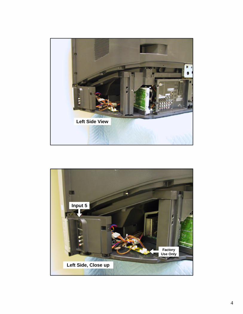
Left Side View
Left Side, Close up
Input 5
Factory Use Only

5
Left Rear View
Center Rear View

6
Right Rear View
Right Side, Close up
Lamp Fan Lamp
Ass’y

7
Right Side, Close up
Lamp Door switch
Chassis Assembly pulled back (L)

8
Chassis Assembly pulled back (R)
Pay close attention to the wiring dress!

9
Cables removed from the Signal PWB (7)
Right Side Cables

10
Right Side, Signal PWB Cables removed (4)
Right Side, Power PWB Cables removed (7)

11
Main ChassisRemoved
PWB Layout
Power PWB
HDMI PWB
Digital PWB
Signal PWB
Tuner PWB
12
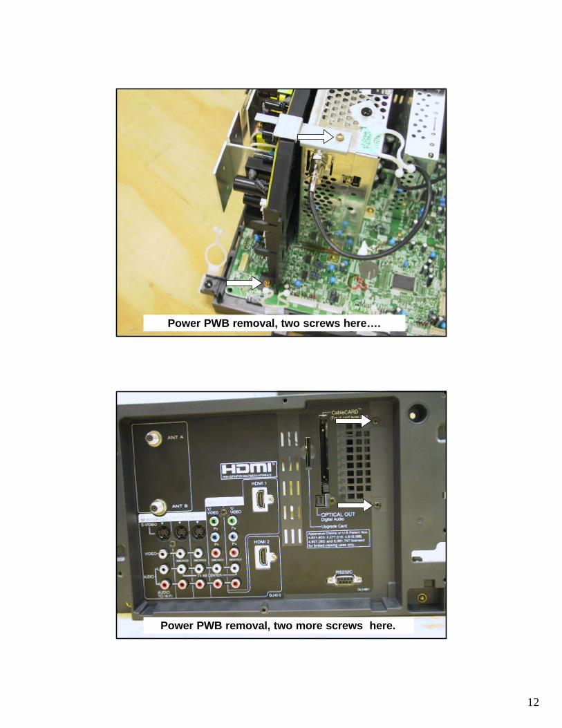
Power PWB removal, two screws here….
Power PWB removal, two more screws here.

13
Power PWB removal, three latches
Power PWB removedNote: These plugs are interchangeable. Make sure the correct cable goes where it should.
14
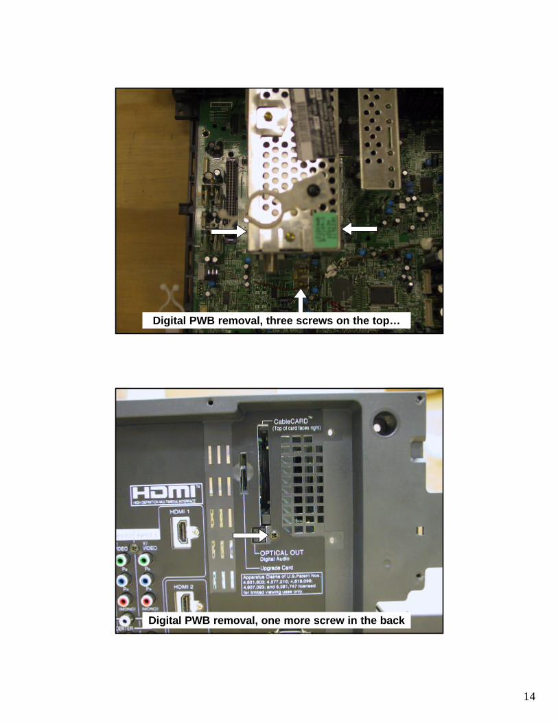
Digital PWB removal, three screws on the top…
Digital PWB removal, one more screw in the back
15
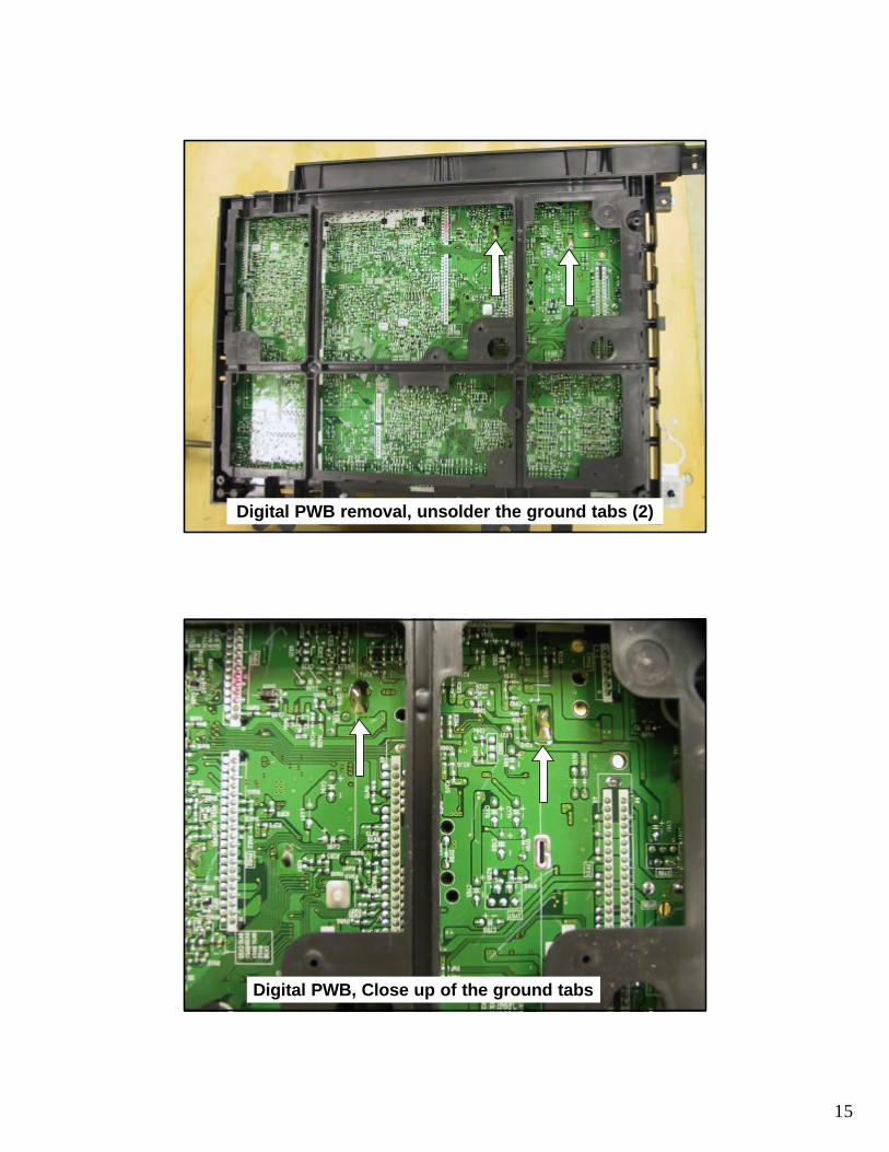
Digital PWB removal, unsolder the ground tabs (2)
Digital PWB, Close up of the ground tabs

16
When removing the Digital PWB, pull very hard, as you must force the latches to let go.
HDMI PWB removal, unsolder the ground tabs (5)
17
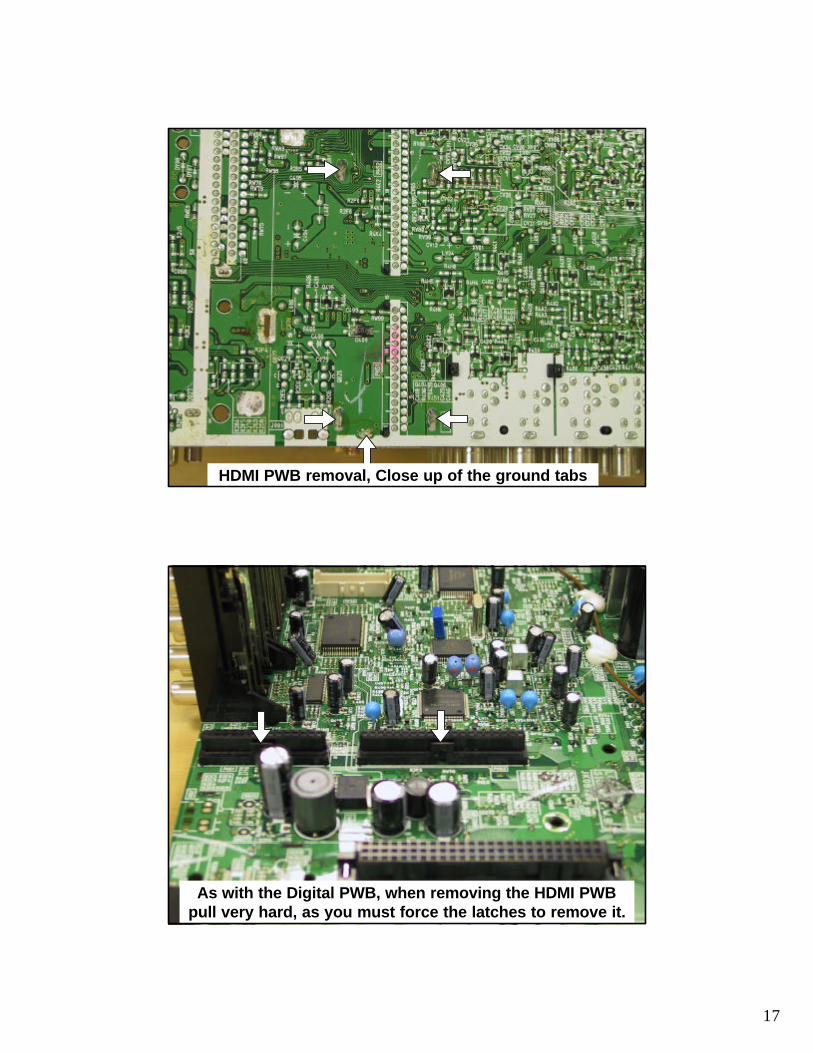
HDMI PWB removal, Close up of the ground tabs
As with the Digital PWB, when removing the HDMI PWB pull very hard, as you must force the latches to remove it.
18
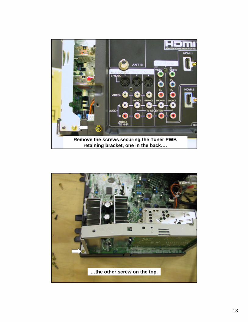
Remove the screws securing the Tuner PWB retaining bracket, one in the back….
…the other screw on the top.
19
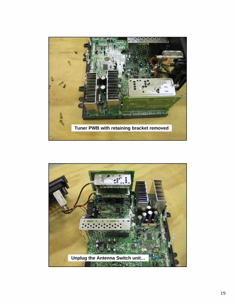
Tuner PWB with retaining bracket removed
Unplug the Antenna Switch unit…
20
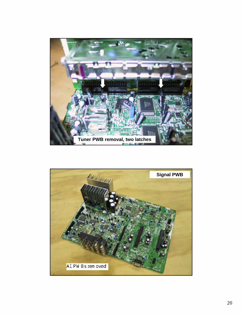
Tuner PWB removal, two latches
Signal PWB
21
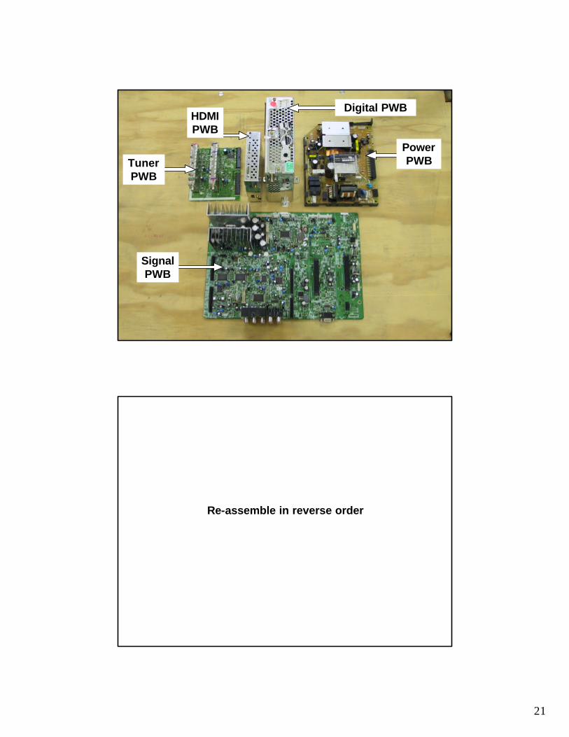
HDMI PWB
Digital PWB
Signal PWB
Tuner PWB
Power PWB
Re-assemble in reverse order
1
•Chassis Assembly ?•Optical Engine Assembly•Top Assembly
LC-48 - 50VS810Disassembly Procedures
2
•Chassis Assembly ?•Optical Engine Assembly
•Rear Support Bracket•IR Sub PWB•Fan PWB•Lamp Power PWB•Lamp Ballast PWB•Optical Engine
•Top Assembly
LC-48 - 50VS810Disassembly Procedures

23
Remove Lower Rear Cover - 24 Screws
Remove Rear Support Bracket
Lower Rear Cover removed

24
Rear Support Bracket removal.
6 screws
Rear Support Bracket removed
Remove Chassis

25
Chassis removed
Remove Sub-IR, Fan, Lamp Power, and Lamp Ballast PWBs
IR-Sub PWB
Fan PWB
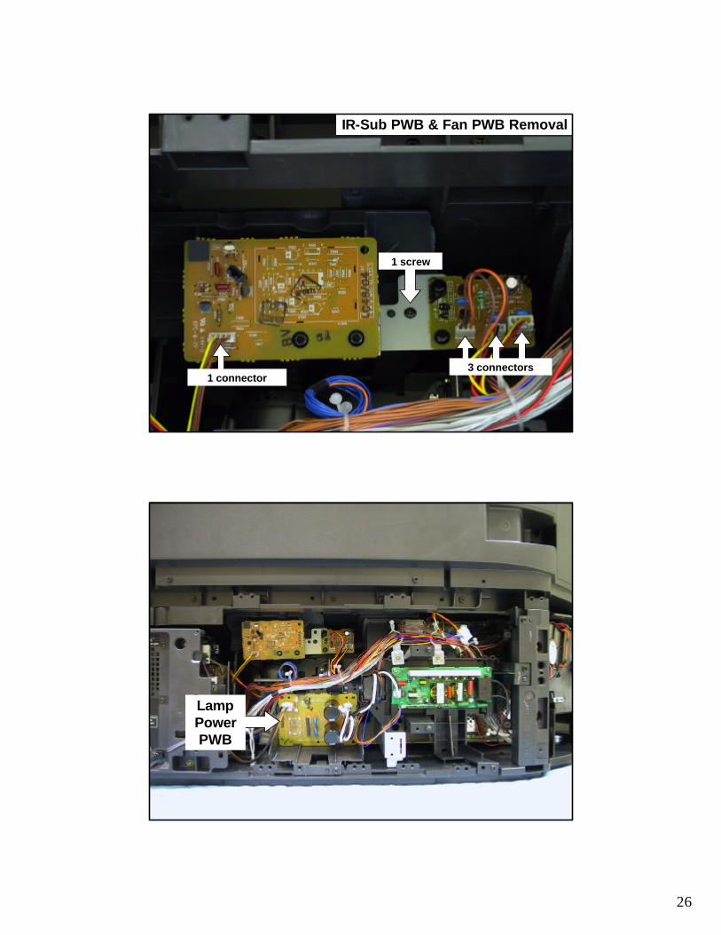
26
1 connector3 connectors
1 screw
IR-Sub PWB & Fan PWB Removal
Lamp Power PWB

27
1 screw
2 wire wraps
2 connectors
Lamp Power PWB Removal
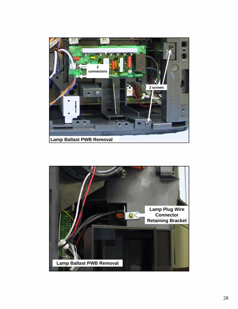
Lamp Ballast PWB
28
2 connectors
2 screws
Lamp Ballast PWB Removal
Lamp Plug Wire Connector
Retaining Bracket
Lamp Ballast PWB Removal
29
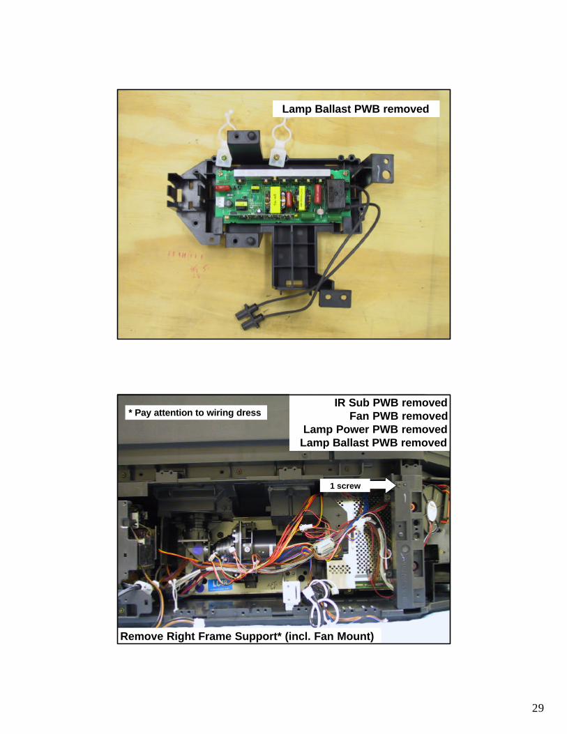
Lamp Ballast PWB removed
IR Sub PWB removedFan PWB removed
Lamp Power PWB removedLamp Ballast PWB removed
Remove Right Frame Support* (incl. Fan Mount)
1 screw
* Pay attention to wiring dress
30
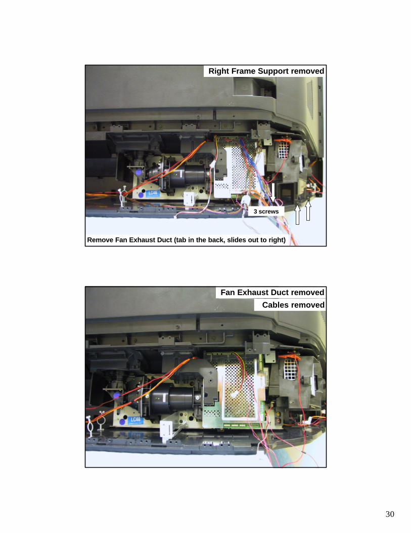
Right Frame Support removed
Remove Fan Exhaust Duct (tab in the back, slides out to right)
3 screws
Fan Exhaust Duct removed
Cables removed

31
Ass’t cables
IR Sub PWB
Fan PWB
Lamp Power PWB
Lamp Ballast PWB
Fan ass’y
Fan Duct
Parts removed prior to Optical Engine removal (pay attention to wiring dress)
Remove Optical Engine* (slides out to right)
* Pay attention to wiring dress
5 screws

32
Re-assemble in reverse order

33

1
•Chassis Assembly ?•Optical Engine Assembly ?•Top Assembly
LC-48 - 50VS810Disassembly Procedures
2
•Chassis Assembly ?•Optical Engine Assembly ?•Top Assembly
•Upper Rear Cover Assembly•Mirror•Sub Woofers
•Front Assembly•Main Speakers•LED PWB•Screen Assembly
LC-48 - 50VS810Disassembly Procedures
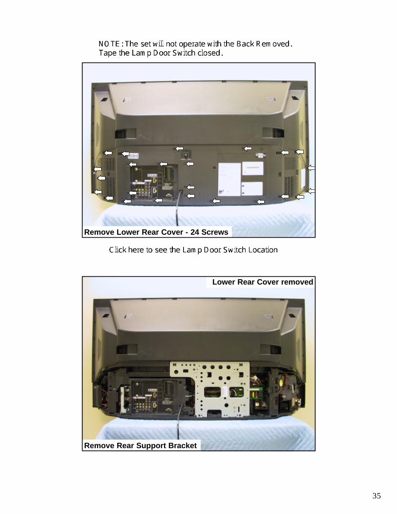
35
Remove Lower Rear Cover - 24 Screws
Remove Rear Support Bracket
Lower Rear Cover removed

36
Rear Support Bracket removal.
6 screws
Remove Input 5 Block
2 screws
Close up left side
Disconnect Left Side Sub-Woofer cable (red/blue)

37
Disconnect Right Side Sub-Woofer cable (red/brown)
Remove Top Assembly (20 screws)
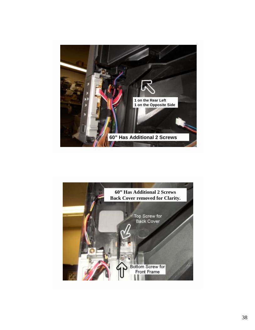
38
60” Has Additional 2 Screws
1 on the Rear Left1 on the Opposite Side
60” Has Additional 2 ScrewsBack Cover removed for Clarity.

39
Remove Top Back Assembly off, pull up & back
Internal View of Top Assembly
Sub Woofer Ports
Mirror
Sub Woofers
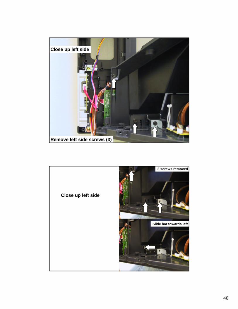
40
Close up left side
Remove left side screws (3)
Close up left side
3 screws removed
Slide bar towards left

41
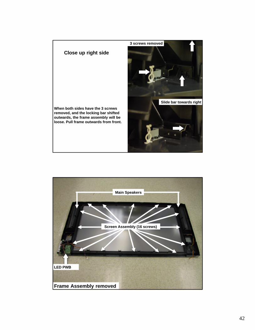
Close up right side
Remove Fan Exhaust Duct - (3 screws, tab in back)
Close up right side
Remove right side screws (3)
42
3 screws removed
Slide bar towards right
Close up right side
When both sides have the 3 screws removed, and the locking bar shifted outwards, the frame assembly will be loose. Pull frame outwards from front.
Frame Assembly removed
LED PWB
Main Speakers
Screen Assembly (16 screws)
43
Re-assemble in reverse order
•Chassis Assembly ?•Optical Engine Assembly ?•Top Assembly ?
LC-48 - 50VS810
Disassembly Procedures Complete

33