Embed Size (px)
Citation preview
Model 961/962
Model 961
Model 962
Installation and Operating Manual
Ultrasonic
Single and
Dual Point
Level Switches
51-646 Echotel® Model 961 & 962 Ultrasonic Level Switches
Read this Manual Before InstallingThis manual provides information on the Echotel®
Models 961 and 962 Ultrasonic Liquid Level Switches.It is important that all instructions are read carefully andfollowed in sequence. Detailed instructions are includedin the Installation section of this manual.
Conventions Used in this ManualCertain conventions are used in this manual to conveyspecific types of information. General technical material,support data, and safety information are presented innarrative form. The following styles are used for notes,cautions, and warnings.
Notes
Notes contain information that augments or clarifiesan operating step. Notes do not normally containactions, they follow the procedural steps to whichthey refer.
Cautions
Cautions alert the technician to special conditionsthat could injure personnel, damage equipment, orreduce a component’s mechanical integrity. Cautionsare also used to alert the technician to unsafe prac-tices or the need for special protective equipment orspecific materials. In this manual, a caution box indi-cates a potentially hazardous situation which, if notavoided, may result in minor or moderate injury.
Warnings
Warnings identify potentially dangerous situations orserious hazards. In this manual, a warning indicatesan imminently hazardous situation which, if notavoided, could result in serious injury or death.
Safety MessagesECHOTEL Models 961 & 962 are designed for use inCategory II, Pollution Degree 2 installations. Follow allstandard industry procedures for servicing electrical andcomputer equipment when working with or around highvoltage. Always shut off the power supply before touch-ing any components.
Electrical components are sensitive to electrostatic dis-charge. To prevent equipment damage, observe safetyprocedures when working with electrostatic sensitivecomponents.
This device complies with Part 15 of the FCC rules.Operation is subject to the following two conditions:(1) This device may not cause harmful interference,and (2) This device must accept any interferencereceived, including interference that may causeundesired operation.
WARNING! Explosion hazard. Do not connect or dis-connect equipment unless power has been switched offor the area is known to be non-hazardous.
Low Voltage DirectiveFor use in Category II installations. If equipment is usedin a manner not specified by manufacturer, protectionprovided by equipment may be impaired.
Notice of Trademark, Copyright, and Limitations
Magnetrol®, Magnetrol® logotype and Echotel® areregistered tradenames of Magnetrol International,Incorporated.®
Copyright © 2011 MAGNETROL INTERNATIONAL,INCORPORATED. All rights reserved.
Performance specifications are effective with date of issueand are subject to change without notice. MAGNETROLreserves the right to make changes to the productdescribed in this manual at any time without notice.MAGNETROL makes no warranty with respect to theaccuracy of the information in this manual.
WarrantyAll MAGNETROL electronic level and flow productsare warranted free of defects in materials or workman-ship for one full year from the date of original factoryshipment.
If returned within the warranty period; and, upon factoryinspection of the control, the cause of the claim isdetermined to be covered under the warranty; then,MAGNETROL will repair or replace the control at nocost to the purchaser (or owner) other than transportation.
MAGNETROL shall not be liable for misapplication,labor claims, direct or consequential damage or expensearising from the installation or use of equipment. Thereare no other warranties expressed or implied, except spe-cial written warranties covering some MAGNETROLproducts.
Quality AssuranceThe quality assurance system in place at MAGNETROLguarantees the highest level of quality throughout thecompany. MAGNETROL is committed to providingfull customer satisfaction both in quality products andquality service.
The MAGNETROL quality assurancesystem is registered to ISO 9001affirming its commitment to knowninternational quality standardsproviding the strongest assurance ofproduct/service quality available.
51-646 Echotel® Model 961 & 962 Ultrasonic Level Switches
Table of Contents
1.0 Introduction ...................................................................41.1 Principle of Operation ..............................................4
2.0 Installation .....................................................................42.1 Unpacking ................................................................42.2 ESD Handling Procedure..........................................52.3 Mounting..................................................................52.4 Wiring ......................................................................6
2.4.1 Model 961 Line-powered Wiring ...................62.4.1.1 Model 961 Remote Transducer
Housing Wiring ......................................72.4.2 Model 961 Loop-powered Wiring..................82.4.2.1 Model 961 Remote Transducer
Housing Wiring ......................................82.4.3 Model 962 Line-powered Wiring ...................92.4.3.1 Model 962 Remote Transducer
Housing Wiring ....................................102.4.4 Model 962 Loop-powered Wiring................112.4.4.1 Model 962 Remote Transducer
Housing Wiring ....................................112.5 Configuration .........................................................12
2.5.1 Model 961 Line-powered Configuration ......122.5.1.1 Time Delay Potentiometer ....................132.5.1.2 Level Test Push Button..........................132.5.1.3 Malfunction Test Push Button ..............132.5.1.4 High/Low DIP Switch ..........................142.5.1.5 Independent/Joint DIP Switch..............14
2.5.2 Model 961 Loop-powered Configuration.....152.5.2.1 Time Delay Potentiometer ....................152.5.2.2 Loop Test Push Button..........................152.5.2.3 Fault Test Push Button..........................152.5.2.4 High/Low DIP Switch ..........................162.5.2.5 22/3.6 DIP Switch ................................16
2.5.3 Model 962 Line-powered Configuration ......172.5.3.1 Time Delay Potentiometer ....................172.5.3.2 Level Test Push Button..........................17
2.5.3.3 Malfunction Test Push Button ..............172.5.3.4 High/Low DIP Switch ..........................182.5.3.5 PC/LC DIP Switch ...............................182.5.3.6 LC and Hi/Lo DIP Switch Configuration 182.5.3.7 PC and Hi/Lo DIP Switch Configuration 19
2.5.4 Model 962 Loop-powered Configuration.....202.5.4.1 Time Delay Potentiometer ....................202.5.4.2 Loop Test Push Button..........................202.5.4.3 Fault Test Push Button..........................202.5.4.4 High/Low DIP Switch ..........................212.5.4.5 22/3.6 DIP Switch ................................21
3.0 Reference Information..................................................223.1 Electronics Specifications ........................................22
3.1.1 Model 961/962 with Relay Output..............223.1.2 Model 961/962 with Current Shift Output .22
3.2 Performance Specifications ......................................223.3 Physical Specifications.............................................223.4 Transducer Specifications ........................................23
3.4.1 Model 9A1/9M1 Single Point ......................233.4.2 Model 9A2/9M2 Dual Point........................23
3.5 Dimensional Specifications .....................................243.6 Agency Approvals....................................................26
3.6.1 Agency (FM/CSA) Drawing andEntity Parameters .........................................27
3.7 Troubleshooting ......................................................283.8 Replacement Parts ...................................................303.9 Model Number .......................................................32
3.9.1 Model 961/962 Electronics ..........................323.9.2 Model 961 Single Point Transducer..............333.9.3 Model 962 Dual Point Transducer ...............343.9.4 Connecting Cable ........................................35
Echotel® Model 961 & 962Ultrasonic Single and Dual Point
Liquid Level Switches
4 51-646 Echotel® Model 961 & 962 Ultrasonic Level Switches
1.0 Introduction
ECHOTEL Model 961 and 962 ultrasonic level switchesutilize pulsed signal technology to detect high, low, or dualpoint level in a broad range of liquid media applications.
Model 961 is a single point level switch. Model 962 is adual point switch used as a level controller or to controlpumps in an auto-fill or auto-empty mode.
1.1 Principle of Operation
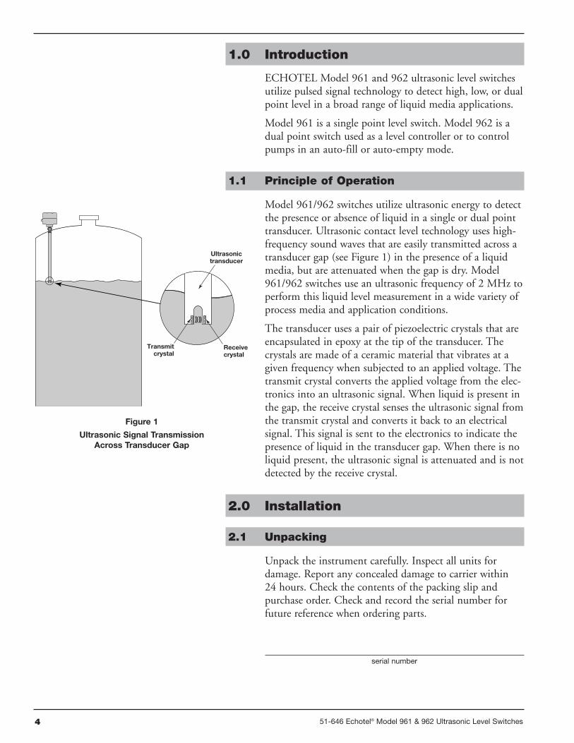
Model 961/962 switches utilize ultrasonic energy to detectthe presence or absence of liquid in a single or dual pointtransducer. Ultrasonic contact level technology uses high-frequency sound waves that are easily transmitted across atransducer gap (see Figure 1) in the presence of a liquidmedia, but are attenuated when the gap is dry. Model961/962 switches use an ultrasonic frequency of 2 MHz toperform this liquid level measurement in a wide variety ofprocess media and application conditions.
The transducer uses a pair of piezoelectric crystals that areencapsulated in epoxy at the tip of the transducer. Thecrystals are made of a ceramic material that vibrates at agiven frequency when subjected to an applied voltage. Thetransmit crystal converts the applied voltage from the elec-tronics into an ultrasonic signal. When liquid is present inthe gap, the receive crystal senses the ultrasonic signal fromthe transmit crystal and converts it back to an electricalsignal. This signal is sent to the electronics to indicate thepresence of liquid in the transducer gap. When there is noliquid present, the ultrasonic signal is attenuated and is notdetected by the receive crystal.
2.0 Installation
2.1 Unpacking
Unpack the instrument carefully. Inspect all units fordamage. Report any concealed damage to carrier within24 hours. Check the contents of the packing slip andpurchase order. Check and record the serial number forfuture reference when ordering parts.
serial number
Ultrasonictransducer
Transmitcrystal
Receivecrystal
Figure 1
Ultrasonic Signal TransmissionAcross Transducer Gap
551-646 Echotel® Model 961 & 962 Ultrasonic Level Switches
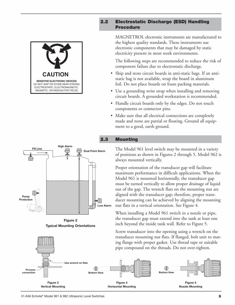
Figure 2
Typical Mounting Orientations
2.2 Electrostatic Discharge (ESD) HandlingProcedure
MAGNETROL electronic instruments are manufactured tothe highest quality standards. These instruments useelectronic components that may be damaged by staticelectricity present in most work environments.
The following steps are recommended to reduce the risk ofcomponent failure due to electrostatic discharge.
• Ship and store circuit boards in anti-static bags. If an anti-static bag is not available, wrap the board in aluminumfoil. Do not place boards on foam packing materials.
• Use a grounding wrist strap when installing and removingcircuit boards. A grounded workstation is recommended.
• Handle circuit boards only by the edges. Do not touchcomponents or connector pins.
• Make sure that all electrical connections are completelymade and none are partial or floating. Ground all equip-ment to a good, earth ground.
2.3 Mounting
The Model 961 level switch may be mounted in a varietyof positions as shown in Figures 2 through 5. Model 962 isalways mounted vertically.
Proper orientation of the transducer gap will facilitatemaximum performance in difficult applications. When theModel 961 is mounted horizontally, the transducer gapmust be turned vertically to allow proper drainage of liquidout of the gap. The wrench flats on the mounting nut arealigned with the transducer gap; therefore, proper trans-ducer mounting can be achieved by aligning the mountingnut flats in a vertical orientation. See Figure 4.
When installing a Model 961 switch in a nozzle or pipe,the transducer gap must extend into the tank at least oneinch beyond the inside tank wall. Refer to Figure 5.
Screw transducer into the opening using a wrench on thetransducer mounting nut flats. If flanged, bolt unit to mat-ing flange with proper gasket. Use thread tape or suitablepipe compound on the threads. Do not over-tighten.
PumpProtection
Fill LineDual Point Alarm
High Alarm
Low Alarm
Figure 3Vertical Mounting
Use wrench on flats
Processconnection Bottom View Bottom View
Figure 4Horizontal Mounting
Figure 5Nozzle Mounting
6 51-646 Echotel® Model 961 & 962 Ultrasonic Level Switches
2.4 Wiring
Wiring for Model 961/962 level switches is different for allfour versions. These switches are available as 4-wire, line-powered units with 5-amp relays, or as 2-wire loop-pow-ered units with mA current shift output. Determine whichversion you have from the table below and proceed to theproper wiring section.
2.4.1 Model 961 Line-powered Wiring
Power and relay wiring connections are suitable for12–24 AWG wire.
Caution: OBSERVE ALL APPLICABLE ELECTRICAL CODESAND PROPER WIRING PROCEDURES.
1. Make sure the power source is turned off.
2. Unscrew and remove housing cover.
3. Pull power supply and relay wires through the conduitconnection.
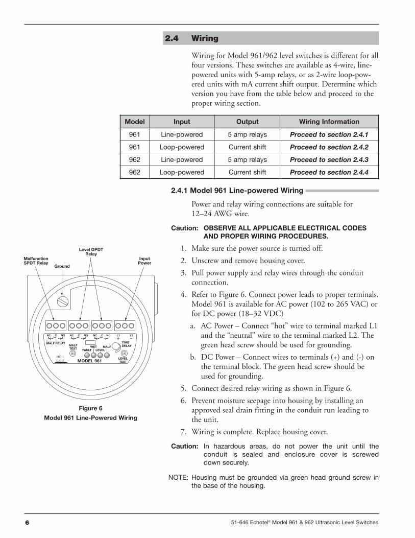
4. Refer to Figure 6. Connect power leads to proper terminals.Model 961 is available for AC power (102 to 265 VAC) orfor DC power (18–32 VDC)
a. AC Power – Connect “hot” wire to terminal marked L1and the “neutral” wire to the terminal marked L2. Thegreen head screw should be used for grounding.
b. DC Power – Connect wires to terminals (+) and (-) onthe terminal block. The green head screw should beused for grounding.
5. Connect desired relay wiring as shown in Figure 6.
6. Prevent moisture seepage into housing by installing anapproved seal drain fitting in the conduit run leading tothe unit.
7. Wiring is complete. Replace housing cover.
Caution: In hazardous areas, do not power the unit until theconduit is sealed and enclosure cover is screweddown securely.
NOTE: Housing must be grounded via green head ground screw inthe base of the housing.
TIMEDELAY
LEVELTEST
MALFTEST
MALF RELAY
FAULTWET
LEVELMALF
MODEL 961
NC C NONC C NO NC C NO L2L1
MalfunctionSPDT Relay
InputPower
Ground
Level DPDTRelay
Hi ILo J
Model Input Output Wiring Information
961 Line-powered 5 amp relays Proceed to section 2.4.1
961 Loop-powered Current shift Proceed to section 2.4.2
962 Line-powered 5 amp relays Proceed to section 2.4.3
962 Loop-powered Current shift Proceed to section 2.4.4
Figure 6
Model 961 Line-Powered Wiring
751-646 Echotel® Model 961 & 962 Ultrasonic Level Switches
2.4.1.1 Model 961 Remote Transducer Housing Wiring
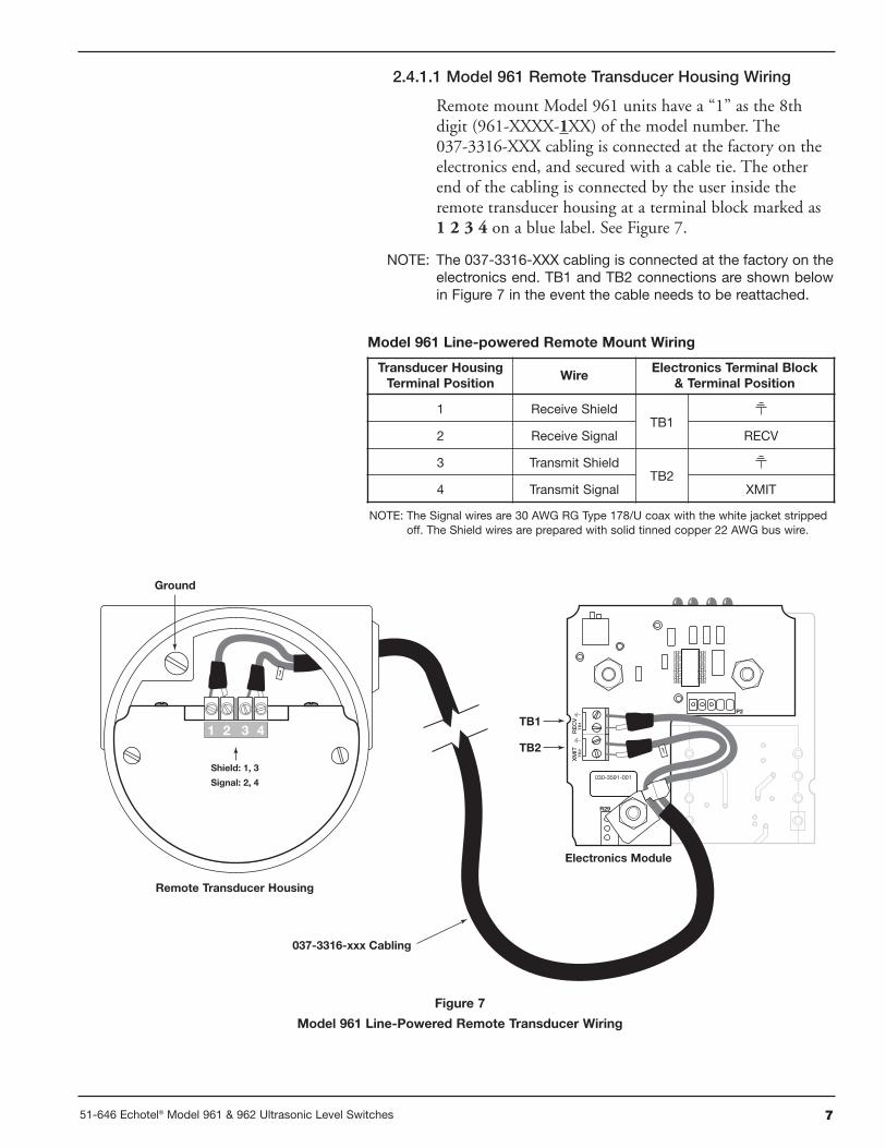
Remote mount Model 961 units have a “1” as the 8thdigit (961-XXXX-1XX) of the model number. The037-3316-XXX cabling is connected at the factory on theelectronics end, and secured with a cable tie. The otherend of the cabling is connected by the user inside theremote transducer housing at a terminal block marked as1 2 3 4 on a blue label. See Figure 7.
NOTE: The 037-3316-XXX cabling is connected at the factory on theelectronics end. TB1 and TB2 connections are shown belowin Figure 7 in the event the cable needs to be reattached.
NOTE: The Signal wires are 30 AWG RG Type 178/U coax with the white jacket strippedoff. The Shield wires are prepared with solid tinned copper 22 AWG bus wire.
Ground
037-3316-xxx Cabling
Shield: 1, 3
Signal: 2, 4030-3591-001
P2
R29
TB
1TB1
TB2
TB
2R
EC
VX
MIT
Figure 7
Model 961 Line-Powered Remote Transducer Wiring
Remote Transducer Housing
Electronics Module
Transducer HousingTerminal Position
WireElectronics Terminal Block
& Terminal Position
1 Receive ShieldTB1
2 Receive Signal RECV
3 Transmit ShieldTB2
4 Transmit Signal XMIT
Model 961 Line-powered Remote Mount Wiring
8 51-646 Echotel® Model 961 & 962 Ultrasonic Level Switches
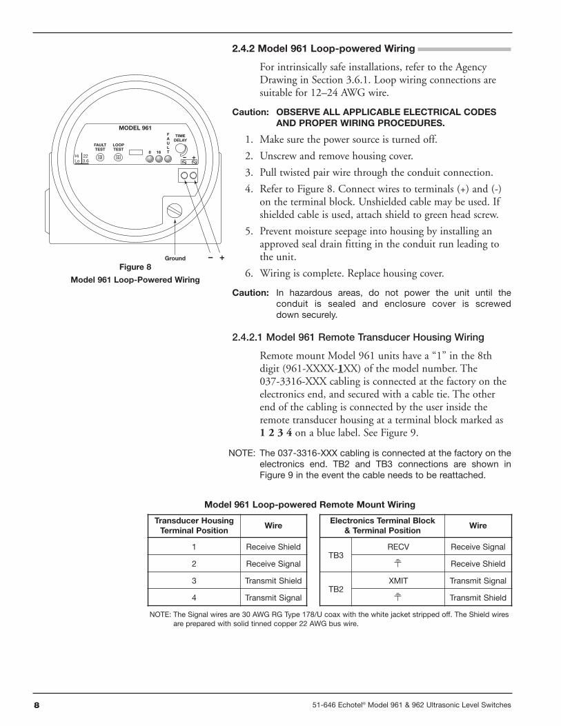
2.4.2 Model 961 Loop-powered Wiring
For intrinsically safe installations, refer to the AgencyDrawing in Section 3.6.1. Loop wiring connections aresuitable for 12–24 AWG wire.
Caution: OBSERVE ALL APPLICABLE ELECTRICAL CODESAND PROPER WIRING PROCEDURES.
1. Make sure the power source is turned off.
2. Unscrew and remove housing cover.
3. Pull twisted pair wire through the conduit connection.
4. Refer to Figure 8. Connect wires to terminals (+) and (-)on the terminal block. Unshielded cable may be used. Ifshielded cable is used, attach shield to green head screw.
5. Prevent moisture seepage into housing by installing anapproved seal drain fitting in the conduit run leading tothe unit.
6. Wiring is complete. Replace housing cover.
Caution: In hazardous areas, do not power the unit until theconduit is sealed and enclosure cover is screweddown securely.
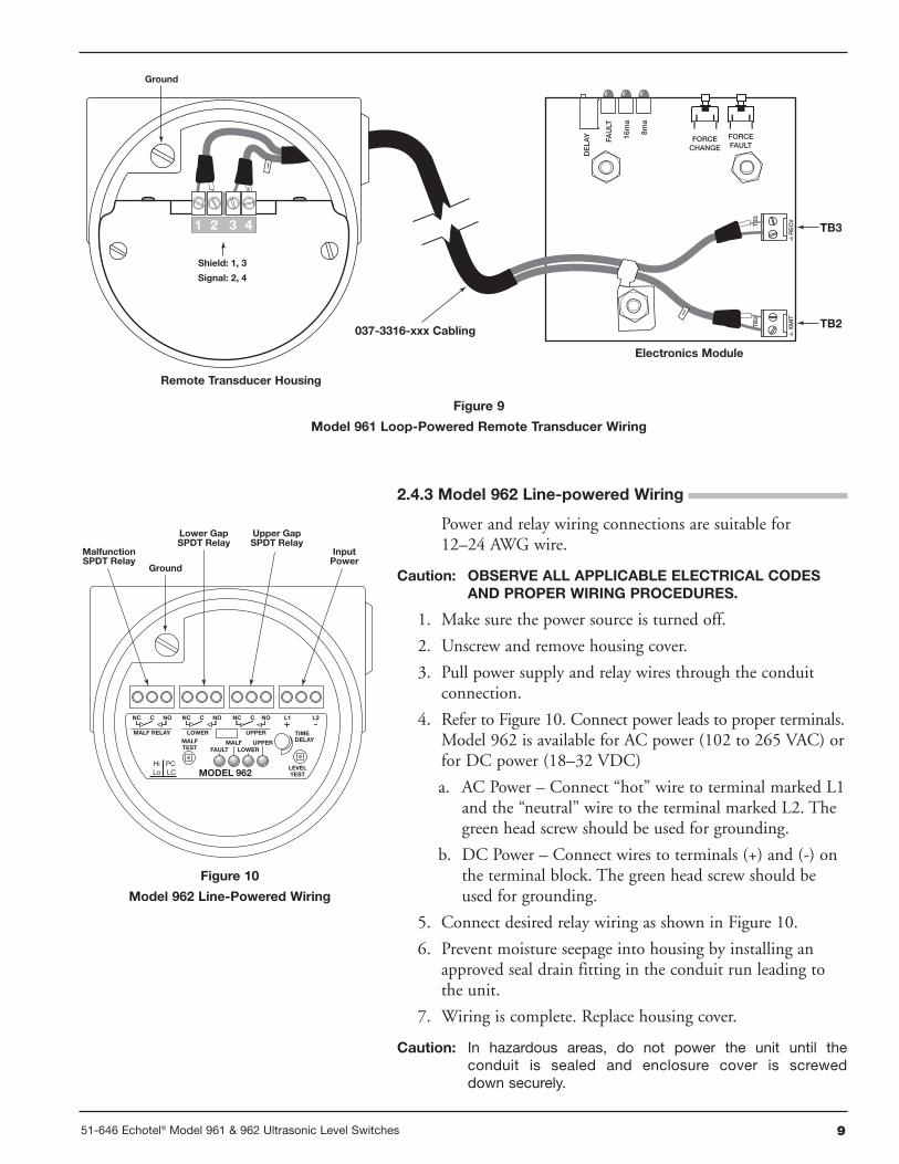
2.4.2.1 Model 961 Remote Transducer Housing Wiring
Remote mount Model 961 units have a “1” in the 8thdigit (961-XXXX-1XX) of the model number. The037-3316-XXX cabling is connected at the factory on theelectronics end, and secured with a cable tie. The otherend of the cabling is connected by the user inside theremote transducer housing at a terminal block marked as1 2 3 4 on a blue label. See Figure 9.
NOTE: The 037-3316-XXX cabling is connected at the factory on theelectronics end. TB2 and TB3 connections are shown inFigure 9 in the event the cable needs to be reattached.
TIMEDELAY
FAULTTEST
MODEL 961
– +
Hi 22Lo 3.6
LOOPTEST
8 16+–
FAULT
Ground
Figure 8
Model 961 Loop-Powered Wiring
Transducer HousingTerminal Position
Wire
1 Receive Shield
2 Receive Signal
3 Transmit Shield
4 Transmit Signal
Electronics Terminal Block& Terminal Position
Wire
TB3RECV Receive Signal
Receive Shield
TB2XMIT Transmit Signal
Transmit Shield
Model 961 Loop-powered Remote Mount Wiring
NOTE: The Signal wires are 30 AWG RG Type 178/U coax with the white jacket stripped off. The Shield wiresare prepared with solid tinned copper 22 AWG bus wire.
951-646 Echotel® Model 961 & 962 Ultrasonic Level Switches
2.4.3 Model 962 Line-powered Wiring
Power and relay wiring connections are suitable for12–24 AWG wire.
Caution: OBSERVE ALL APPLICABLE ELECTRICAL CODESAND PROPER WIRING PROCEDURES.
1. Make sure the power source is turned off.
2. Unscrew and remove housing cover.
3. Pull power supply and relay wires through the conduitconnection.
4. Refer to Figure 10. Connect power leads to proper terminals.Model 962 is available for AC power (102 to 265 VAC) orfor DC power (18–32 VDC)
a. AC Power – Connect “hot” wire to terminal marked L1and the “neutral” wire to the terminal marked L2. Thegreen head screw should be used for grounding.
b. DC Power – Connect wires to terminals (+) and (-) onthe terminal block. The green head screw should beused for grounding.
5. Connect desired relay wiring as shown in Figure 10.
6. Prevent moisture seepage into housing by installing anapproved seal drain fitting in the conduit run leading tothe unit.
7. Wiring is complete. Replace housing cover.
Caution: In hazardous areas, do not power the unit until theconduit is sealed and enclosure cover is screweddown securely.
TIMEDELAY
LEVELTEST
MALFTEST
MALF RELAY
FAULTMALF
LOWERUPPER
MODEL 962
NC C NONC C NO NC C NO L2L1
MalfunctionSPDT Relay
InputPower
Ground
Lower GapSPDT Relay
Upper GapSPDT Relay
Hi PCLo LC
LOWER UPPER
Figure 10
Model 962 Line-Powered Wiring
Ground
Shield: 1, 3
Signal: 2, 4
TB
3
DE
LAY
FAU
LT
16m
a
8ma
FORCECHANGE
FORCEFAULT
TB
2
XM
IT TB2
TB3RE
CV
037-3316-xxx Cabling
Figure 9
Model 961 Loop-Powered Remote Transducer Wiring
Remote Transducer Housing
Electronics Module
10 51-646 Echotel® Model 961 & 962 Ultrasonic Level Switches
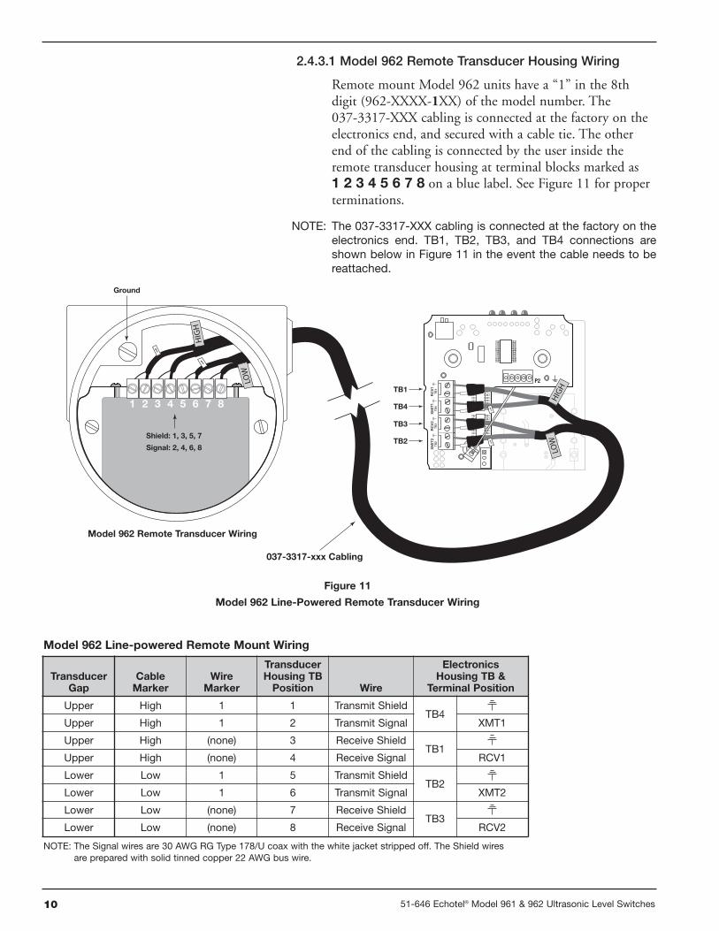
2.4.3.1 Model 962 Remote Transducer Housing Wiring
Remote mount Model 962 units have a “1” in the 8thdigit (962-XXXX-1XX) of the model number. The037-3317-XXX cabling is connected at the factory on theelectronics end, and secured with a cable tie. The otherend of the cabling is connected by the user inside theremote transducer housing at terminal blocks marked as1 2 3 4 5 6 7 8 on a blue label. See Figure 11 for properterminations.
NOTE: The 037-3317-XXX cabling is connected at the factory on theelectronics end. TB1, TB2, TB3, and TB4 connections areshown below in Figure 11 in the event the cable needs to bereattached.
P2
TB
1TB1
TB4
TB
4R
CV
1X
MIT
1T
B3TB3
TB2T
B2
RC
V2
XM
IT2
037-3317-xxx Cabling
Ground
Shield: 1, 3, 5, 7
Signal: 2, 4, 6, 8
Model 962 Remote Transducer Wiring
Figure 11
Model 962 Line-Powered Remote Transducer Wiring
TransducerGap
CableMarker
WireMarker
TransducerHousing TBPosition Wire
ElectronicsHousing TB &
Terminal Position
Upper High 1 1 Transmit ShieldTB4
Upper High 1 2 Transmit Signal XMT1
Upper High (none) 3 Receive ShieldTB1
Upper High (none) 4 Receive Signal RCV1
Lower Low 1 5 Transmit ShieldTB2
Lower Low 1 6 Transmit Signal XMT2
Lower Low (none) 7 Receive ShieldTB3
Lower Low (none) 8 Receive Signal RCV2
Model 962 Line-powered Remote Mount Wiring
NOTE: The Signal wires are 30 AWG RG Type 178/U coax with the white jacket stripped off. The Shield wiresare prepared with solid tinned copper 22 AWG bus wire.
1151-646 Echotel® Model 961 & 962 Ultrasonic Level Switches
TIMEDELAY
FAULTTEST
MODEL 962
– +
Hi 22Lo 3.6
LOOPTEST
8 12 16+–
Ground
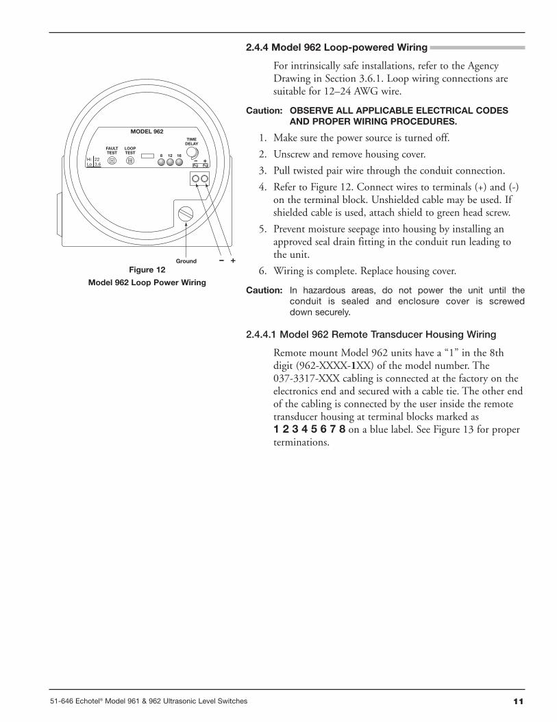
Figure 12
Model 962 Loop Power Wiring
2.4.4 Model 962 Loop-powered Wiring
For intrinsically safe installations, refer to the AgencyDrawing in Section 3.6.1. Loop wiring connections aresuitable for 12–24 AWG wire.
Caution: OBSERVE ALL APPLICABLE ELECTRICAL CODESAND PROPER WIRING PROCEDURES.
1. Make sure the power source is turned off.
2. Unscrew and remove housing cover.
3. Pull twisted pair wire through the conduit connection.
4. Refer to Figure 12. Connect wires to terminals (+) and (-)on the terminal block. Unshielded cable may be used. Ifshielded cable is used, attach shield to green head screw.
5. Prevent moisture seepage into housing by installing anapproved seal drain fitting in the conduit run leading tothe unit.
6. Wiring is complete. Replace housing cover.
Caution: In hazardous areas, do not power the unit until theconduit is sealed and enclosure cover is screweddown securely.
2.4.4.1 Model 962 Remote Transducer Housing Wiring
Remote mount Model 962 units have a “1” in the 8thdigit (962-XXXX-1XX) of the model number. The037-3317-XXX cabling is connected at the factory on theelectronics end and secured with a cable tie. The other endof the cabling is connected by the user inside the remotetransducer housing at terminal blocks marked as1 2 3 4 5 6 7 8 on a blue label. See Figure 13 for properterminations.
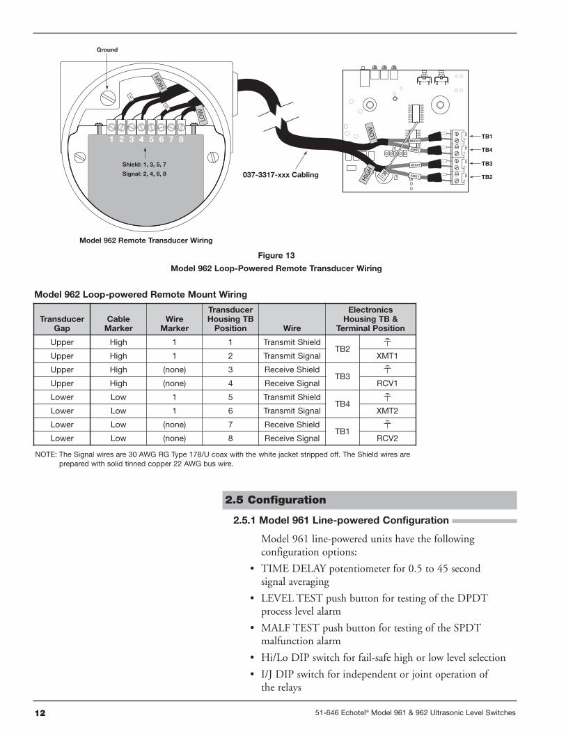
12 51-646 Echotel® Model 961 & 962 Ultrasonic Level Switches
TB
1
TB1
TB4TB
4T
B3
TB3
TB2TB
2
RECV1
XMIT1
RECV2
XMIT2
037-3317-xxx Cabling
Ground
Shield: 1, 3, 5, 7
Signal: 2, 4, 6, 8
Model 962 Remote Transducer Wiring
Figure 13
Model 962 Loop-Powered Remote Transducer Wiring
TransducerGap
CableMarker
WireMarker
TransducerHousing TBPosition Wire
ElectronicsHousing TB &
Terminal Position
Upper High 1 1 Transmit ShieldTB2
Upper High 1 2 Transmit Signal XMT1
Upper High (none) 3 Receive ShieldTB3
Upper High (none) 4 Receive Signal RCV1
Lower Low 1 5 Transmit ShieldTB4
Lower Low 1 6 Transmit Signal XMT2
Lower Low (none) 7 Receive ShieldTB1
Lower Low (none) 8 Receive Signal RCV2
Model 962 Loop-powered Remote Mount Wiring
2.5 Configuration
2.5.1 Model 961 Line-powered Configuration
Model 961 line-powered units have the followingconfiguration options:
• TIME DELAY potentiometer for 0.5 to 45 secondsignal averaging
• LEVEL TEST push button for testing of the DPDTprocess level alarm
• MALF TEST push button for testing of the SPDTmalfunction alarm
• Hi/Lo DIP switch for fail-safe high or low level selection
• I/J DIP switch for independent or joint operation ofthe relays
NOTE: The Signal wires are 30 AWG RG Type 178/U coax with the white jacket stripped off. The Shield wires areprepared with solid tinned copper 22 AWG bus wire.
1351-646 Echotel® Model 961 & 962 Ultrasonic Level Switches
TIMEDELAY
LEVELTEST
MALFTEST
MALF RELAY
FAULTWET
LEVELMALF
MODEL 961
NC C NONC C NO NC C NO L2L1
High/LowDIP Switch
Independent/JointDIP Switch
Level TestPushbutton
Malfunction TestPushbutton
Hi ILo J
Time Delay Pot
to decrease delay
to increase delay
Turn
Turn
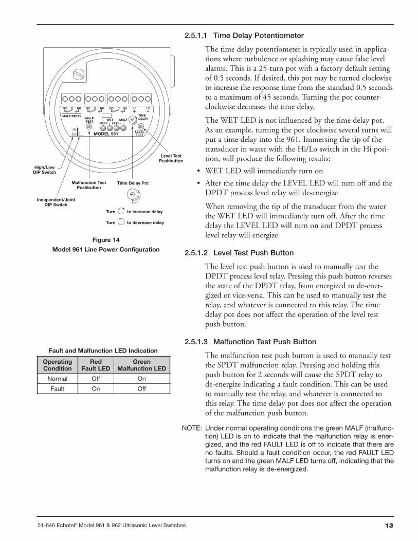
Figure 14
Model 961 Line Power Configuration
2.5.1.1 Time Delay Potentiometer
The time delay potentiometer is typically used in applica-tions where turbulence or splashing may cause false levelalarms. This is a 25-turn pot with a factory default settingof 0.5 seconds. If desired, this pot may be turned clockwiseto increase the response time from the standard 0.5 secondsto a maximum of 45 seconds. Turning the pot counter-clockwise decreases the time delay.
The WET LED is not influenced by the time delay pot.As an example, turning the pot clockwise several turns willput a time delay into the 961. Immersing the tip of thetransducer in water with the Hi/Lo switch in the Hi posi-tion, will produce the following results:
• WET LED will immediately turn on
• After the time delay the LEVEL LED will turn off and theDPDT process level relay will de-energize
When removing the tip of the transducer from the waterthe WET LED will immediately turn off. After the timedelay the LEVEL LED will turn on and DPDT processlevel relay will energize.
2.5.1.2 Level Test Push Button
The level test push button is used to manually test theDPDT process level relay. Pressing this push button reversesthe state of the DPDT relay, from energized to de-ener-gized or vice-versa. This can be used to manually test therelay, and whatever is connected to this relay. The timedelay pot does not affect the operation of the level testpush button.
2.5.1.3 Malfunction Test Push Button
The malfunction test push button is used to manually testthe SPDT malfunction relay. Pressing and holding thispush button for 2 seconds will cause the SPDT relay tode-energize indicating a fault condition. This can be usedto manually test the relay, and whatever is connected tothis relay. The time delay pot does not affect the operationof the malfunction push button.
NOTE: Under normal operating conditions the green MALF (malfunc-tion) LED is on to indicate that the malfunction relay is ener-gized, and the red FAULT LED is off to indicate that there areno faults. Should a fault condition occur, the red FAULT LEDturns on and the green MALF LED turns off, indicating that themalfunction relay is de-energized.
OperatingCondition
RedFault LED
GreenMalfunction LED
Normal Off On
Fault On Off
Fault and Malfunction LED Indication
14 51-646 Echotel® Model 961 & 962 Ultrasonic Level Switches
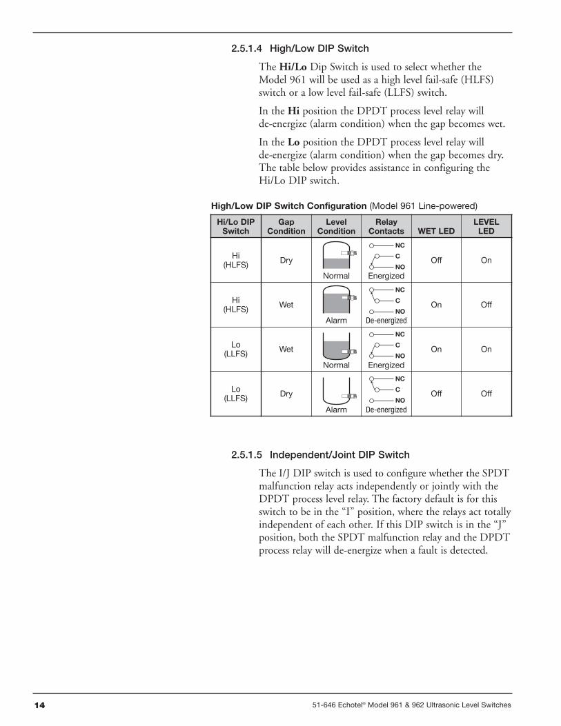
2.5.1.4 High/Low DIP Switch
The Hi/Lo Dip Switch is used to select whether theModel 961 will be used as a high level fail-safe (HLFS)switch or a low level fail-safe (LLFS) switch.
In the Hi position the DPDT process level relay willde-energize (alarm condition) when the gap becomes wet.
In the Lo position the DPDT process level relay willde-energize (alarm condition) when the gap becomes dry.The table below provides assistance in configuring theHi/Lo DIP switch.
Hi/Lo DIPSwitch
GapCondition
LevelCondition
RelayContacts WET LED
LEVELLED
Hi(HLFS) Dry
NC
C
NOOff On
Hi(HLFS) Wet
NC
C
NOOn Off
Lo(LLFS) Wet
NC
C
NOOn On
Lo(LLFS) Dry
NC
C
NOOff Off
High/Low DIP Switch Configuration (Model 961 Line-powered)
Normal
Alarm
Normal
Alarm
Energized
De-energized
Energized
De-energized
2.5.1.5 Independent/Joint DIP Switch
The I/J DIP switch is used to configure whether the SPDTmalfunction relay acts independently or jointly with theDPDT process level relay. The factory default is for thisswitch to be in the “I” position, where the relays act totallyindependent of each other. If this DIP switch is in the “J”position, both the SPDT malfunction relay and the DPDTprocess relay will de-energize when a fault is detected.
1551-646 Echotel® Model 961 & 962 Ultrasonic Level Switches
TIMEDELAY
FAULTTEST
MODEL 961
Hi 22Lo 3.6
LOOPTEST
+–8 16
FAULT
High/LowDIP Switch
22/3.6 mADIP Switch
Fault TestPush Button
Loop TestPush Button
Time Delay Pot
to decrease delay
to increase delay
Turn
Turn
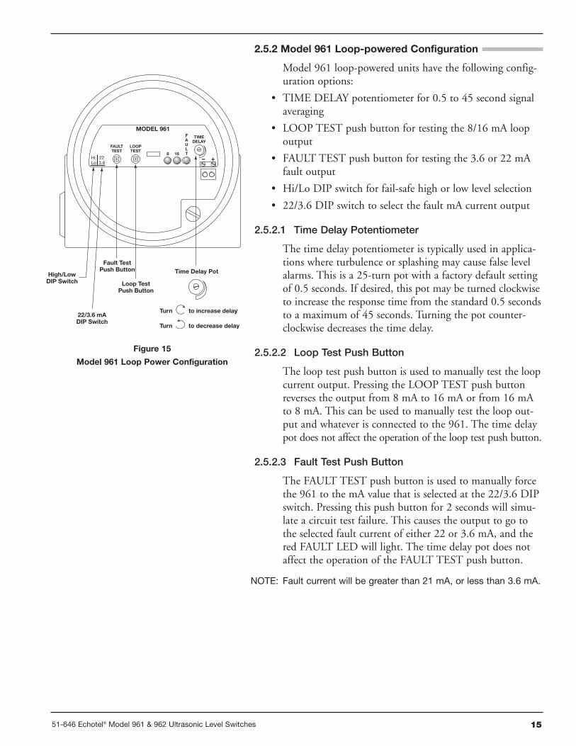
Figure 15
Model 961 Loop Power Configuration
2.5.2 Model 961 Loop-powered Configuration
Model 961 loop-powered units have the following config-uration options:
• TIME DELAY potentiometer for 0.5 to 45 second signalaveraging
• LOOP TEST push button for testing the 8/16 mA loopoutput
• FAULT TEST push button for testing the 3.6 or 22 mAfault output
• Hi/Lo DIP switch for fail-safe high or low level selection
• 22/3.6 DIP switch to select the fault mA current output
2.5.2.1 Time Delay Potentiometer
The time delay potentiometer is typically used in applica-tions where turbulence or splashing may cause false levelalarms. This is a 25-turn pot with a factory default settingof 0.5 seconds. If desired, this pot may be turned clockwiseto increase the response time from the standard 0.5 secondsto a maximum of 45 seconds. Turning the pot counter-clockwise decreases the time delay.
2.5.2.2 Loop Test Push Button
The loop test push button is used to manually test the loopcurrent output. Pressing the LOOP TEST push buttonreverses the output from 8 mA to 16 mA or from 16 mAto 8 mA. This can be used to manually test the loop out-put and whatever is connected to the 961. The time delaypot does not affect the operation of the loop test push button.
2.5.2.3 Fault Test Push Button
The FAULT TEST push button is used to manually forcethe 961 to the mA value that is selected at the 22/3.6 DIPswitch. Pressing this push button for 2 seconds will simu-late a circuit test failure. This causes the output to go tothe selected fault current of either 22 or 3.6 mA, and thered FAULT LED will light. The time delay pot does notaffect the operation of the FAULT TEST push button.
NOTE: Fault current will be greater than 21 mA, or less than 3.6 mA.
16 51-646 Echotel® Model 961 & 962 Ultrasonic Level Switches
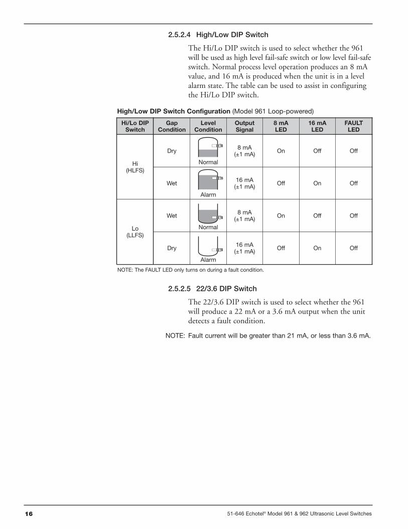
2.5.2.4 High/Low DIP Switch
The Hi/Lo DIP switch is used to select whether the 961will be used as high level fail-safe switch or low level fail-safeswitch. Normal process level operation produces an 8 mAvalue, and 16 mA is produced when the unit is in a levelalarm state. The table can be used to assist in configuringthe Hi/Lo DIP switch.
2.5.2.5 22/3.6 DIP Switch
The 22/3.6 DIP switch is used to select whether the 961will produce a 22 mA or a 3.6 mA output when the unitdetects a fault condition.
NOTE: Fault current will be greater than 21 mA, or less than 3.6 mA.
Hi/Lo DIPSwitch
GapCondition
LevelCondition
OutputSignal
8 mALED
16 mALED
FAULTLED
Hi(HLFS)
Dry 8 mA(±1 mA) On Off Off
Wet 16 mA(±1 mA) Off On Off
Lo(LLFS)
Wet 8 mA(±1 mA) On Off Off
Dry 16 mA(±1 mA) Off On Off
High/Low DIP Switch Configuration (Model 961 Loop-powered)
NOTE: The FAULT LED only turns on during a fault condition.
Normal
Alarm
Normal
Alarm
1751-646 Echotel® Model 961 & 962 Ultrasonic Level Switches
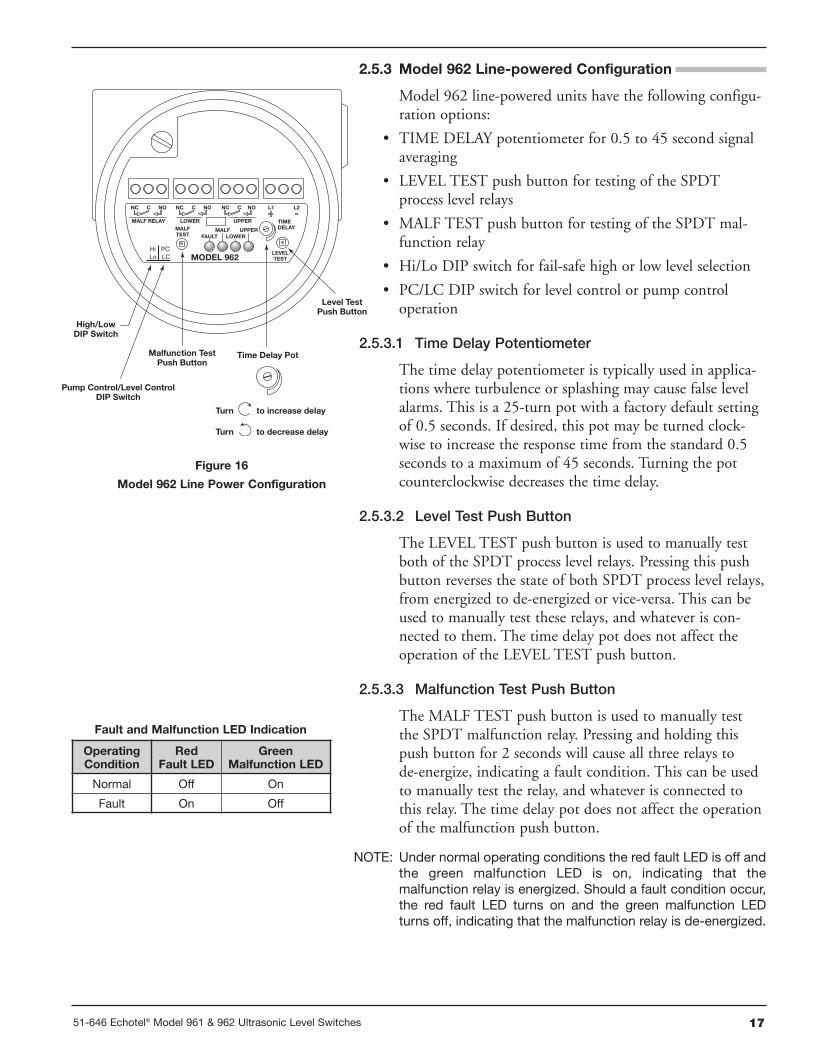
2.5.3 Model 962 Line-powered Configuration
Model 962 line-powered units have the following configu-ration options:
• TIME DELAY potentiometer for 0.5 to 45 second signalaveraging
• LEVEL TEST push button for testing of the SPDTprocess level relays
• MALF TEST push button for testing of the SPDT mal-function relay
• Hi/Lo DIP switch for fail-safe high or low level selection
• PC/LC DIP switch for level control or pump controloperation
2.5.3.1 Time Delay Potentiometer
The time delay potentiometer is typically used in applica-tions where turbulence or splashing may cause false levelalarms. This is a 25-turn pot with a factory default settingof 0.5 seconds. If desired, this pot may be turned clock-wise to increase the response time from the standard 0.5seconds to a maximum of 45 seconds. Turning the potcounterclockwise decreases the time delay.
2.5.3.2 Level Test Push Button
The LEVEL TEST push button is used to manually testboth of the SPDT process level relays. Pressing this pushbutton reverses the state of both SPDT process level relays,from energized to de-energized or vice-versa. This can beused to manually test these relays, and whatever is con-nected to them. The time delay pot does not affect theoperation of the LEVEL TEST push button.
2.5.3.3 Malfunction Test Push Button
The MALF TEST push button is used to manually testthe SPDT malfunction relay. Pressing and holding thispush button for 2 seconds will cause all three relays tode-energize, indicating a fault condition. This can be usedto manually test the relay, and whatever is connected tothis relay. The time delay pot does not affect the operationof the malfunction push button.
NOTE: Under normal operating conditions the red fault LED is off andthe green malfunction LED is on, indicating that themalfunction relay is energized. Should a fault condition occur,the red fault LED turns on and the green malfunction LEDturns off, indicating that the malfunction relay is de-energized.
TIMEDELAY
LEVELTEST
MALFTEST
MALF RELAY
FAULTMALF
LOWERUPPER
MODEL 962
NC C NONC C NO NC C NO L2L1
Hi PCLo LC
LOWER UPPER
High/LowDIP Switch
Pump Control/Level ControlDIP Switch
Level TestPush Button
Malfunction TestPush Button
Time Delay Pot
to decrease delay
to increase delay
Turn
Turn
Figure 16
Model 962 Line Power Configuration
OperatingCondition
RedFault LED
GreenMalfunction LED
Normal Off On
Fault On Off
Fault and Malfunction LED Indication
18 51-646 Echotel® Model 961 & 962 Ultrasonic Level Switches
2.5.3.4 High/Low DIP Switch
The Hi/Lo DIP switch is used to select whether the 962will be used as a high level fail-safe (HLFS) switch or lowlevel fail-safe (LLFS) switch. The setting of the Hi/Lo DIPalso affects how the PC/LC DIP switch configures theunit. Read Section 2.5.3.5 below and then proceed to theappropriate table in Section 2.5.3.6 or 2.5.3.7 for propersetting of the DIP switches.
2.5.3.5 PC/LC DIP Switch
The PC/LC DIP switch is used to select whether the 962will operate in a pump control or a level control mode.Select LC to use the 962 as a level controller where therelays operate independently of each other. Select PC tooperate the 962 as a pump controller where the relays latchto enable an auto fill or auto empty mode.
The configuration tables (Section 2.5.3.6 & 2.5.3.7) areused for proper setting of the Hi/Lo and PC/LC DIPswitches. They also indicate the status of the yellowLOWER and UPPER LEDs. The green MALF (malfunc-tion) LED and the red FAULT LEDs are not included inthese tables.
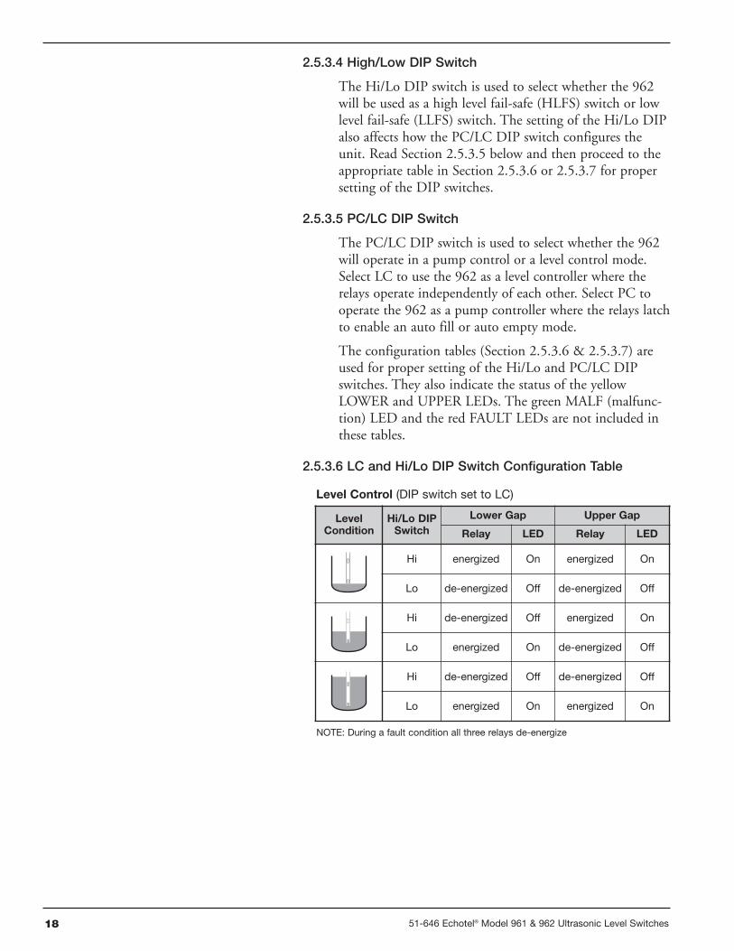
2.5.3.6 LC and Hi/Lo DIP Switch Configuration Table
LevelCondition
Hi/Lo DIPSwitch
Lower Gap Upper Gap
Relay LED Relay LED
Hi energized On energized On
Lo de-energized Off de-energized Off
Hi de-energized Off energized On
Lo energized On de-energized Off
Hi de-energized Off de-energized Off
Lo energized On energized On
Level Control (DIP switch set to LC)
NOTE: During a fault condition all three relays de-energize
1951-646 Echotel® Model 961 & 962 Ultrasonic Level Switches
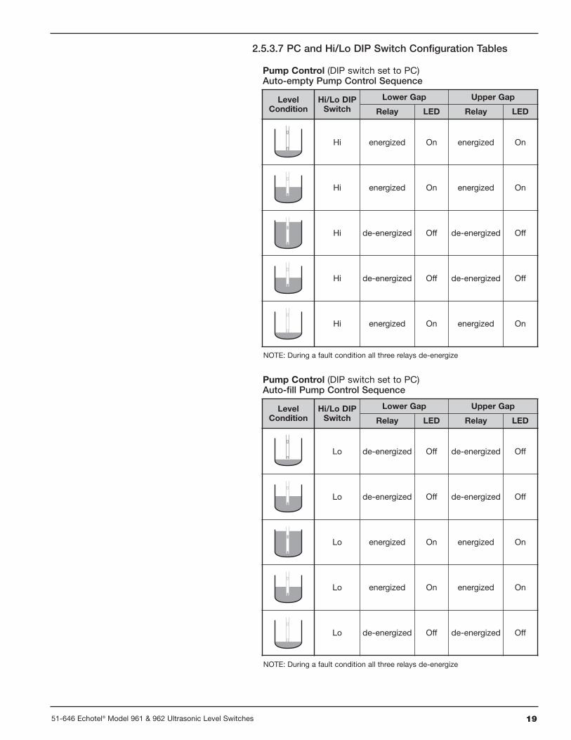
2.5.3.7 PC and Hi/Lo DIP Switch Configuration Tables
LevelCondition
Hi/Lo DIPSwitch
Lower Gap Upper Gap
Relay LED Relay LED
Hi energized On energized On
Hi energized On energized On
Hi de-energized Off de-energized Off
Hi de-energized Off de-energized Off
Hi energized On energized On
Pump Control (DIP switch set to PC)Auto-empty Pump Control Sequence
NOTE: During a fault condition all three relays de-energize
LevelCondition
Hi/Lo DIPSwitch
Lower Gap Upper Gap
Relay LED Relay LED
Lo de-energized Off de-energized Off
Lo de-energized Off de-energized Off
Lo energized On energized On
Lo energized On energized On
Lo de-energized Off de-energized Off
Pump Control (DIP switch set to PC)Auto-fill Pump Control Sequence
NOTE: During a fault condition all three relays de-energize
20 51-646 Echotel® Model 961 & 962 Ultrasonic Level Switches
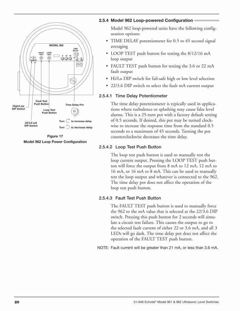
2.5.4 Model 962 Loop-powered Configuration
Model 962 loop-powered units have the following config-uration options:
• TIME DELAY potentiometer for 0.5 to 45 second signalaveraging
• LOOP TEST push button for testing the 8/12/16 mAloop output
• FAULT TEST push button for testing the 3.6 or 22 mAfault output
• Hi/Lo DIP switch for fail-safe high or low level selection
• 22/3.6 DIP switch to select the fault mA current output
2.5.4.1 Time Delay Potentiometer
The time delay potentiometer is typically used in applica-tions where turbulence or splashing may cause false levelalarms. This is a 25-turn pot with a factory default settingof 0.5 seconds. If desired, this pot may be turned clock-wise to increase the response time from the standard 0.5seconds to a maximum of 45 seconds. Turning the potcounterclockwise decreases the time delay.
2.5.4.2 Loop Test Push Button
The loop test push button is used to manually test theloop current output. Pressing the LOOP TEST push but-ton will force the output from 8 mA to 12 mA, 12 mA to16 mA, or 16 mA to 8 mA. This can be used to manuallytest the loop output and whatever is connected to the 962.The time delay pot does not affect the operation of theloop test push button.
2.5.4.3 Fault Test Push Button
The FAULT TEST push button is used to manually forcethe 962 to the mA value that is selected at the 22/3.6 DIPswitch. Pressing this push button for 2 seconds will simu-late a circuit test failure. This causes the output to go tothe selected fault current of either 22 or 3.6 mA, and all 3LEDs will go dark. The time delay pot does not affect theoperation of the FAULT TEST push button.
NOTE: Fault current will be greater than 21 mA, or less than 3.6 mA.
TIMEDELAY
FAULTTEST
MODEL 962
Hi 22Lo 3.6
LOOPTEST
8 12 16+–
High/LowDIP Switch
22/3.6 mADIP Switch
Fault TestPush Button
Loop TestPush Button
Time Delay Pot
to decrease delay
to increase delay
Turn
Turn
Figure 17
Model 962 Loop Power Configuration
2151-646 Echotel® Model 961 & 962 Ultrasonic Level Switches
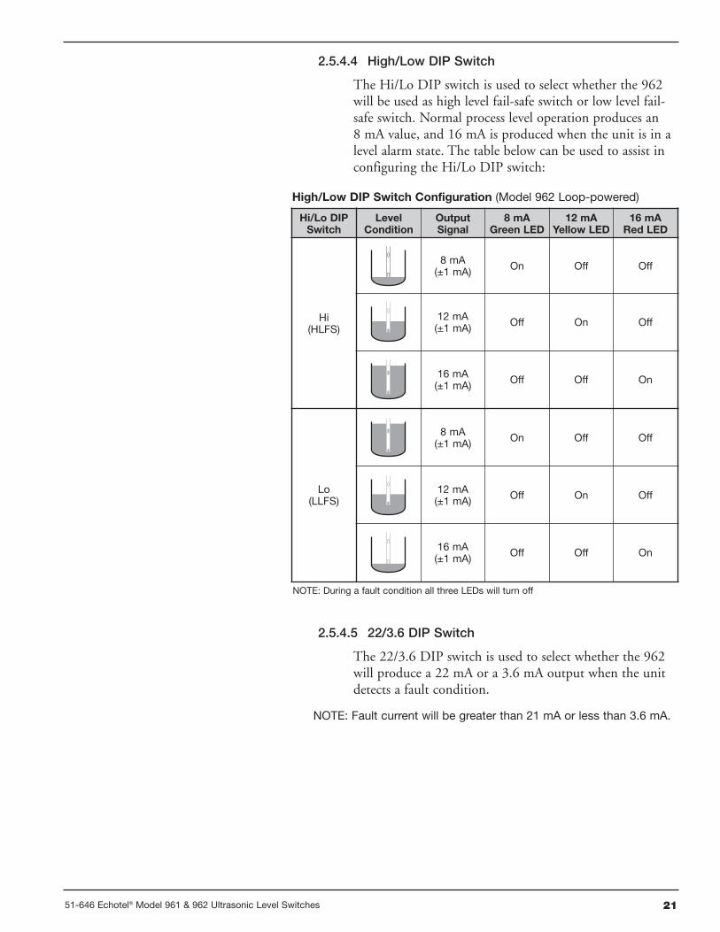
2.5.4.4 High/Low DIP Switch
The Hi/Lo DIP switch is used to select whether the 962will be used as high level fail-safe switch or low level fail-safe switch. Normal process level operation produces an8 mA value, and 16 mA is produced when the unit is in alevel alarm state. The table below can be used to assist inconfiguring the Hi/Lo DIP switch:
2.5.4.5 22/3.6 DIP Switch
The 22/3.6 DIP switch is used to select whether the 962will produce a 22 mA or a 3.6 mA output when the unitdetects a fault condition.
NOTE: Fault current will be greater than 21 mA or less than 3.6 mA.
Hi/Lo DIPSwitch
LevelCondition
OutputSignal
8 mAGreen LED
12 mAYellow LED
16 mARed LED
Hi(HLFS)
8 mA(±1 mA) On Off Off
12 mA(±1 mA) Off On Off
16 mA(±1 mA) Off Off On
Lo(LLFS)
8 mA(±1 mA) On Off Off
12 mA(±1 mA) Off On Off
16 mA(±1 mA) Off Off On
High/Low DIP Switch Configuration (Model 962 Loop-powered)
NOTE: During a fault condition all three LEDs will turn off
22 51-646 Echotel® Model 961 & 962 Ultrasonic Level Switches
3.0 Reference Information
3.1 Electronics Specifications
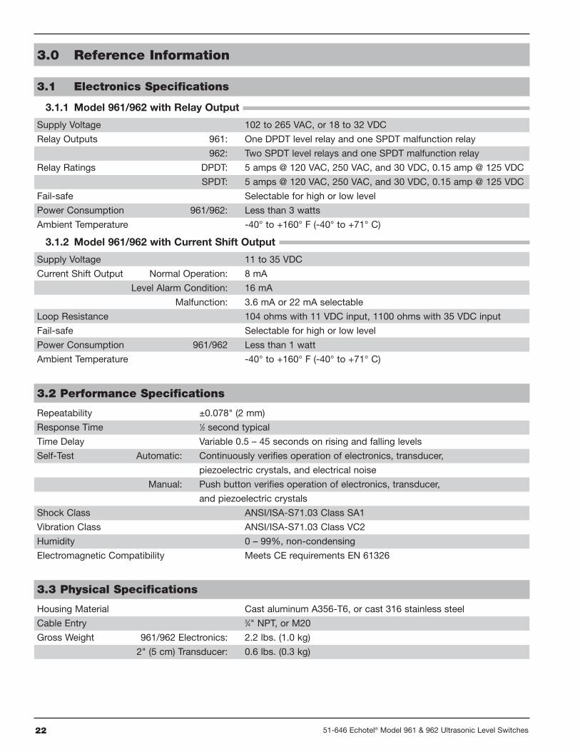
3.1.1 Model 961/962 with Relay Output
Supply Voltage 102 to 265 VAC, or 18 to 32 VDC
Relay Outputs 961: One DPDT level relay and one SPDT malfunction relay
962: Two SPDT level relays and one SPDT malfunction relay
Relay Ratings DPDT: 5 amps @ 120 VAC, 250 VAC, and 30 VDC, 0.15 amp @ 125 VDC
SPDT: 5 amps @ 120 VAC, 250 VAC, and 30 VDC, 0.15 amp @ 125 VDC
Fail-safe Selectable for high or low level
Power Consumption 961/962: Less than 3 watts
Ambient Temperature -40° to +160° F (-40° to +71° C)
3.1.2 Model 961/962 with Current Shift Output
Supply Voltage 11 to 35 VDC
Current Shift Output Normal Operation: 8 mA
Level Alarm Condition: 16 mA
Malfunction: 3.6 mA or 22 mA selectable
Loop Resistance 104 ohms with 11 VDC input, 1100 ohms with 35 VDC input
Fail-safe Selectable for high or low level
Power Consumption 961/962 Less than 1 watt
Ambient Temperature -40° to +160° F (-40° to +71° C)
3.2 Performance Specifications
Repeatability ±0.078" (2 mm)
Response Time 1⁄2 second typical
Time Delay Variable 0.5 – 45 seconds on rising and falling levels
Self-Test Automatic: Continuously verifies operation of electronics, transducer,
piezoelectric crystals, and electrical noise
Manual: Push button verifies operation of electronics, transducer,
and piezoelectric crystals
Shock Class ANSI/ISA-S71.03 Class SA1
Vibration Class ANSI/ISA-S71.03 Class VC2
Humidity 0 – 99%, non-condensing
Electromagnetic Compatibility Meets CE requirements EN 61326
3.3 Physical Specifications
Housing Material Cast aluminum A356-T6, or cast 316 stainless steel
Cable Entry 3⁄4" NPT, or M20
Gross Weight 961/962 Electronics: 2.2 lbs. (1.0 kg)
2" (5 cm) Transducer: 0.6 lbs. (0.3 kg)
2351-646 Echotel® Model 961 & 962 Ultrasonic Level Switches
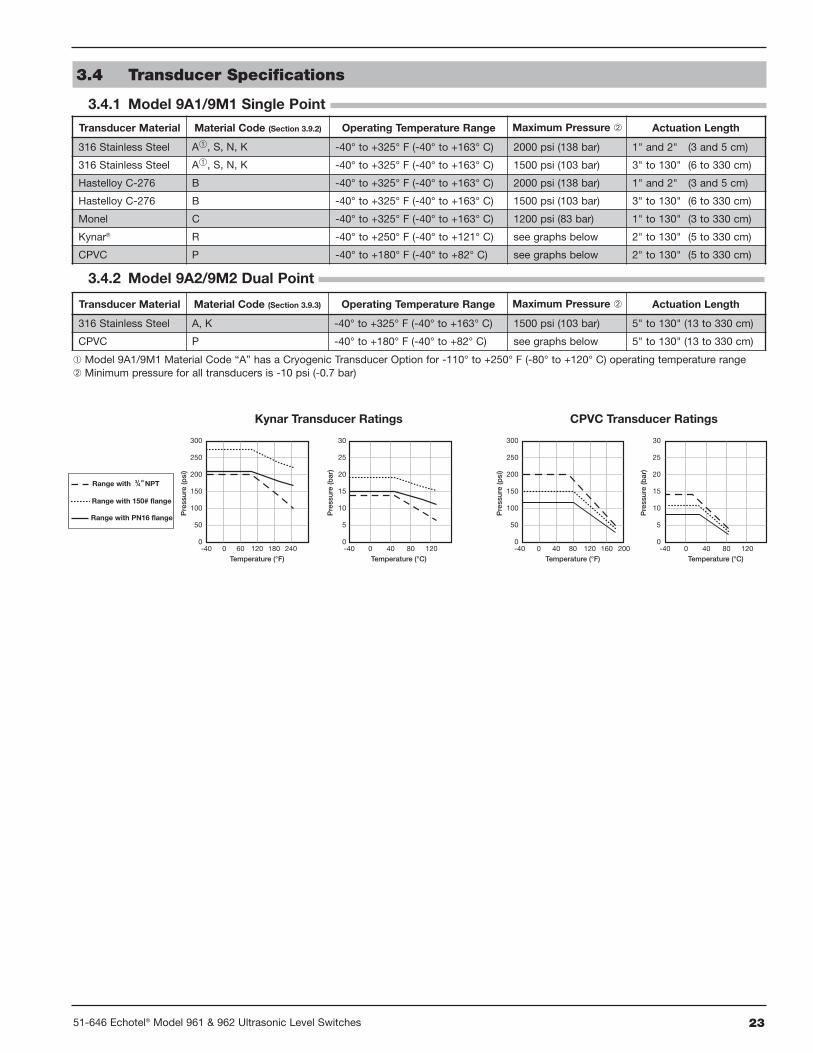
3.4 Transducer Specifications
3.4.1 Model 9A1/9M1 Single Point
Transducer Material Material Code (Section 3.9.2) Operating Temperature Range Maximum Pressure � Actuation Length
316 Stainless Steel A�, S, N, K -40° to +325° F (-40° to +163° C) 2000 psi (138 bar) 1" and 2" (3 and 5 cm)
316 Stainless Steel A�, S, N, K -40° to +325° F (-40° to +163° C) 1500 psi (103 bar) 3" to 130" (6 to 330 cm)
Hastelloy C-276 B -40° to +325° F (-40° to +163° C) 2000 psi (138 bar) 1" and 2" (3 and 5 cm)
Hastelloy C-276 B -40° to +325° F (-40° to +163° C) 1500 psi (103 bar) 3" to 130" (6 to 330 cm)
Monel C -40° to +325° F (-40° to +163° C) 1200 psi (83 bar) 1" to 130" (3 to 330 cm)
Kynar® R -40° to +250° F (-40° to +121° C) see graphs below 2" to 130" (5 to 330 cm)
CPVC P -40° to +180° F (-40° to +82° C) see graphs below 2" to 130" (5 to 330 cm)
Transducer Material Material Code (Section 3.9.3) Operating Temperature Range Maximum Pressure � Actuation Length
316 Stainless Steel A, K -40° to +325° F (-40° to +163° C) 1500 psi (103 bar) 5" to 130" (13 to 330 cm)
CPVC P -40° to +180° F (-40° to +82° C) see graphs below 5" to 130" (13 to 330 cm)
3.4.2 Model 9A2/9M2 Dual Point
300
250
200
150
100
50
-40 0 60 120 180 2400
Pre
ssur
e(p
si)
Temperature (°F)
30
25
20
15
10
5
-40 0 40 80 1200
Pre
ssur
e(b
ar)
Temperature (°C)
Range with PN16 flange
Range with 150# flange
Range with "NPT
300
250
200
150
100
50
-40 0 40 80 120 160 2000
Pre
ssur
e(p
si)
Temperature (°F)
30
25
20
15
10
5
-40 0 40 80 1200
Pre
ssur
e(b
ar)
Temperature (°C)
Kynar Transducer Ratings CPVC Transducer Ratings
� Model 9A1/9M1 Material Code “A” has a Cryogenic Transducer Option for -110° to +250° F (-80° to +120° C) operating temperature range� Minimum pressure for all transducers is -10 psi (-0.7 bar)
24 51-646 Echotel® Model 961 & 962 Ultrasonic Level Switches
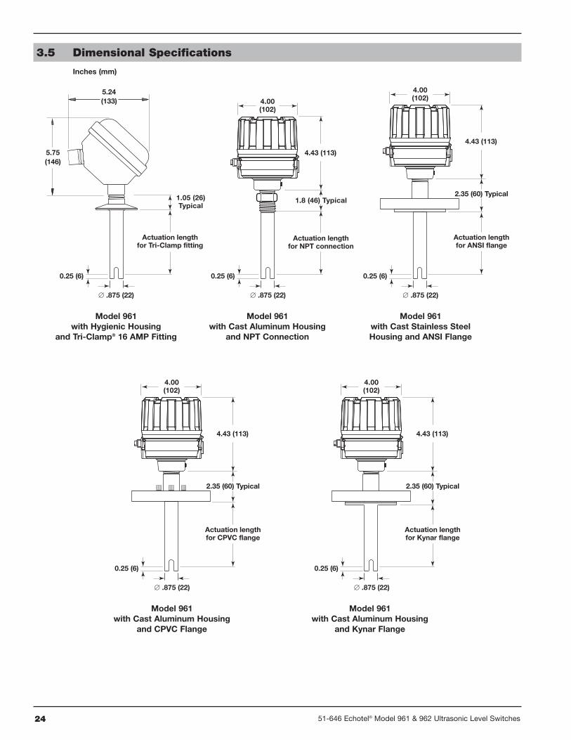
Model 961with Hygienic Housing
and Tri-Clamp® 16 AMP Fitting
Model 961with Cast Aluminum Housing
and NPT Connection
Model 961with Cast Stainless SteelHousing and ANSI Flange
1.8 (46) Typical1.05 (26)Typical
4.00(102)4.00
(102)
∅ .875 (22)∅ .875 (22)∅ .875 (22)
Actuation lengthfor Tri-Clamp fitting
4.43 (113)
4.43 (113)
0.25 (6) 0.25 (6)0.25 (6)
Actuation lengthfor NPT connection
Actuation lengthfor ANSI flange
2.35 (60) Typical
5.24(133)
5.75(146)
Model 961with Cast Aluminum Housing
and CPVC Flange
Model 961with Cast Aluminum Housing
and Kynar Flange
4.00(102)
4.00(102)
∅ .875 (22)
4.43 (113)
0.25 (6)
Actuation lengthfor Kynar flange
2.35 (60) Typical
∅ .875 (22)
4.43 (113)
0.25 (6)
Actuation lengthfor CPVC flange
2.35 (60) Typical
3.5 Dimensional Specifications
Inches (mm)
2551-646 Echotel® Model 961 & 962 Ultrasonic Level Switches
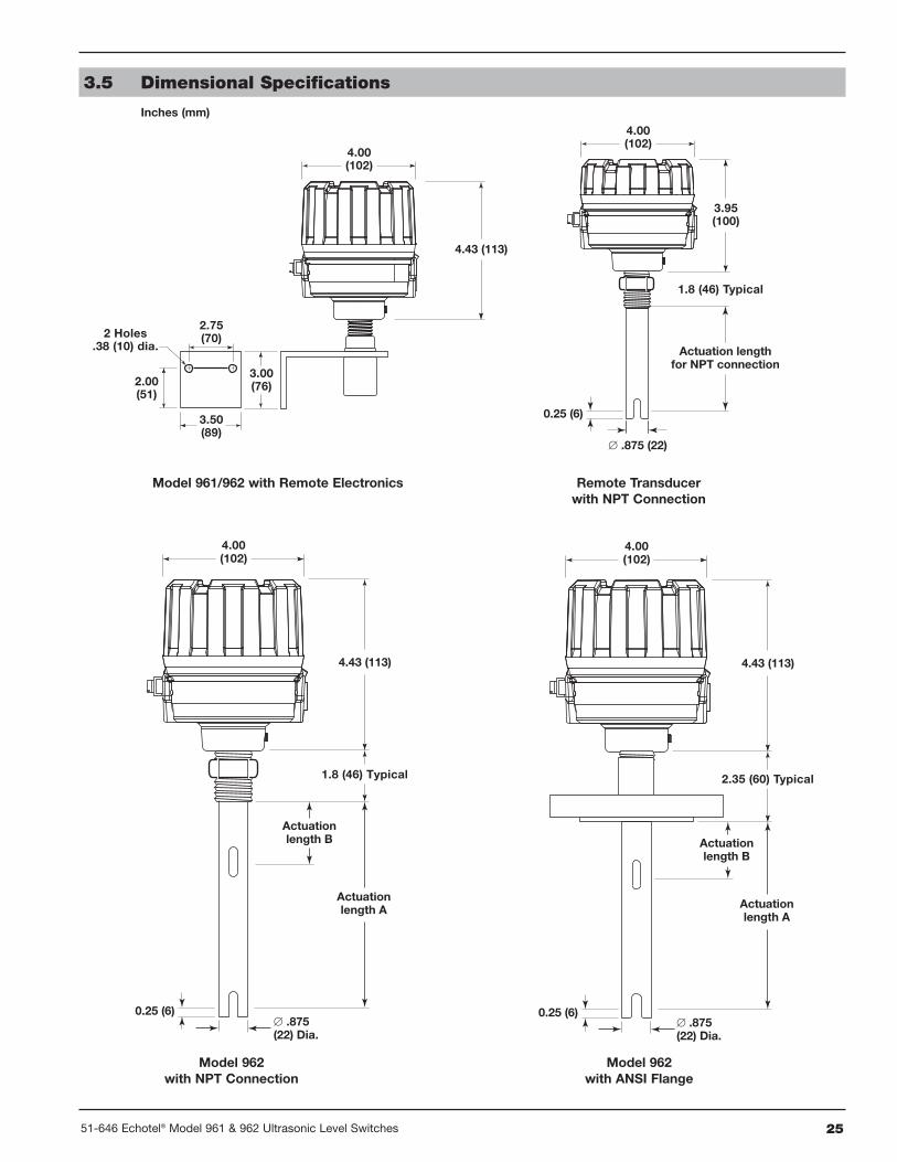
Actuationlength A
Actuationlength B
∅ .875(22) Dia.
4.00(102)
4.43 (113)
1.8 (46) Typical
0.25 (6)
3.50(89)
2.75(70)
2.00(51)
3.00(76)
2 Holes.38 (10) dia.
4.00(102)
4.00(102)
3.95(100)
4.43 (113)
∅ .875 (22)
0.25 (6)
Actuation lengthfor NPT connection
1.8 (46) Typical
Model 961/962 with Remote Electronics Remote Transducerwith NPT Connection
Model 962with NPT Connection
Actuationlength A
Actuationlength B
∅ .875(22) Dia.
4.00(102)
4.43 (113)
2.35 (60) Typical
0.25 (6)
Model 962with ANSI Flange
3.5 Dimensional Specifications
Inches (mm)
26 51-646 Echotel® Model 961 & 962 Ultrasonic Level Switches
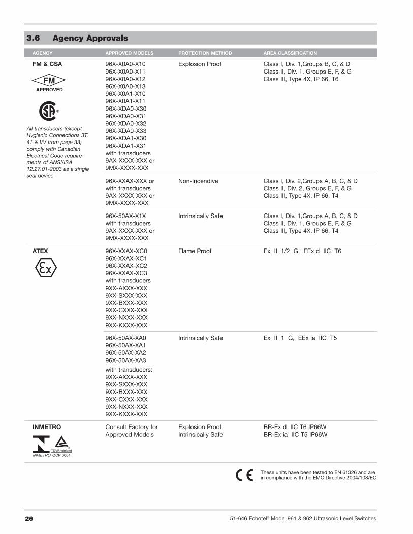
3.6 Agency Approvals
AGENCY APPROVED MODELS PROTECTION METHOD AREA CLASSIFICATION
FM & CSA 96X-X0A0-X10 Explosion Proof Class I, Div. 1,Groups B, C, & D96X-X0A0-X11 Class II, Div. 1, Groups E, F, & G96X-X0A0-X12 Class III, Type 4X, IP 66, T696X-X0A0-X1396X-X0A1-X1096X-X0A1-X1196X-XDA0-X3096X-XDA0-X3196X-XDA0-X3296X-XDA0-X3396X-XDA1-X3096X-XDA1-X31with transducers9AX-XXXX-XXX or9MX-XXXX-XXX
96X-XXAX-XXX or Non-Incendive Class I, Div. 2,Groups A, B, C, & Dwith transducers Class II, Div. 2, Groups E, F, & G9AX-XXXX-XXX or Class III, Type 4X, IP 66, T49MX-XXXX-XXX
96X-50AX-X1X Intrinsically Safe Class I, Div. 1,Groups A, B, C, & Dwith transducers Class II, Div. 1, Groups E, F, & G9AX-XXXX-XXX or Class III, Type 4X, IP 66, T49MX-XXXX-XXX
ATEX 96X-XXAX-XC0 Flame Proof Ex II 1/2 G, EEx d IIC T696X-XXAX-XC196X-XXAX-XC296X-XXAX-XC3with transducers9XX-AXXX-XXX9XX-SXXX-XXX9XX-BXXX-XXX9XX-CXXX-XXX9XX-NXXX-XXX9XX-KXXX-XXX
96X-50AX-XA0 Intrinsically Safe Ex II 1 G, EEx ia IIC T596X-50AX-XA196X-50AX-XA296X-50AX-XA3
with transducers:9XX-AXXX-XXX9XX-SXXX-XXX9XX-BXXX-XXX9XX-CXXX-XXX9XX-NXXX-XXX9XX-KXXX-XXX
INMETRO Consult Factory for Explosion Proof BR-Ex d IIC T6 IP66WApproved Models Intrinsically Safe BR-Ex ia IIC T5 IP66W
These units have been tested to EN 61326 and arein compliance with the EMC Directive 2004/108/EC.
All transducers (exceptHygienic Connections 3T,4T & VV from page 33)comply with CanadianElectrical Code require-ments of ANSI/ISA12.27.01-2003 as a singleseal device
2751-646 Echotel® Model 961 & 962 Ultrasonic Level Switches
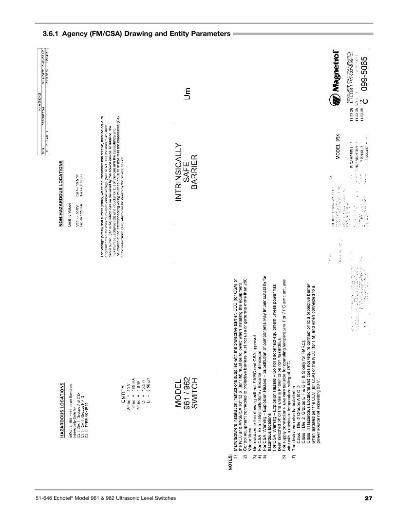
3.6.1 Agency (FM/CSA) Drawing and Entity Parameters
28 51-646 Echotel® Model 961 & 962 Ultrasonic Level Switches
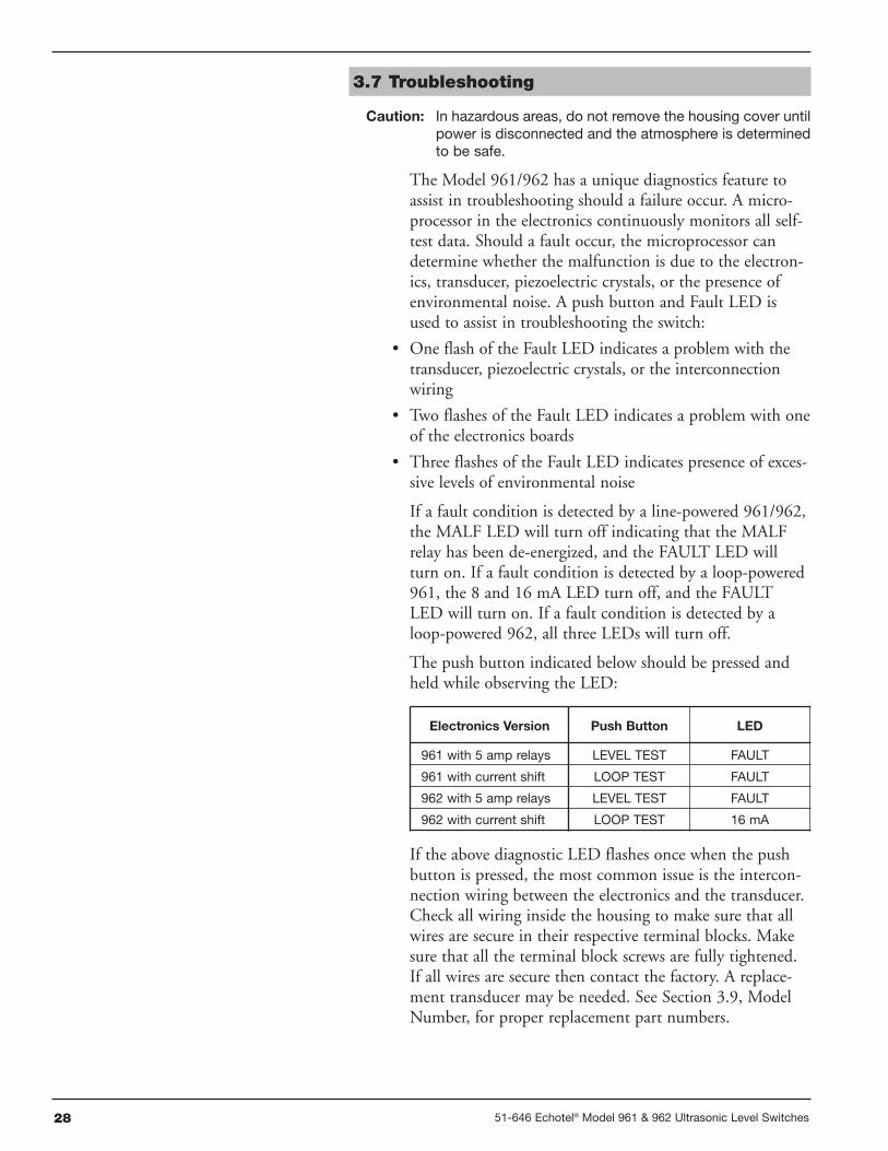
3.7 Troubleshooting
Caution: In hazardous areas, do not remove the housing cover untilpower is disconnected and the atmosphere is determinedto be safe.
The Model 961/962 has a unique diagnostics feature toassist in troubleshooting should a failure occur. A micro-processor in the electronics continuously monitors all self-test data. Should a fault occur, the microprocessor candetermine whether the malfunction is due to the electron-ics, transducer, piezoelectric crystals, or the presence ofenvironmental noise. A push button and Fault LED isused to assist in troubleshooting the switch:
• One flash of the Fault LED indicates a problem with thetransducer, piezoelectric crystals, or the interconnectionwiring
• Two flashes of the Fault LED indicates a problem with oneof the electronics boards
• Three flashes of the Fault LED indicates presence of exces-sive levels of environmental noise
If a fault condition is detected by a line-powered 961/962,the MALF LED will turn off indicating that the MALFrelay has been de-energized, and the FAULT LED willturn on. If a fault condition is detected by a loop-powered961, the 8 and 16 mA LED turn off, and the FAULTLED will turn on. If a fault condition is detected by aloop-powered 962, all three LEDs will turn off.
The push button indicated below should be pressed andheld while observing the LED:
If the above diagnostic LED flashes once when the pushbutton is pressed, the most common issue is the intercon-nection wiring between the electronics and the transducer.Check all wiring inside the housing to make sure that allwires are secure in their respective terminal blocks. Makesure that all the terminal block screws are fully tightened.If all wires are secure then contact the factory. A replace-ment transducer may be needed. See Section 3.9, ModelNumber, for proper replacement part numbers.
Electronics Version Push Button LED
961 with 5 amp relays LEVEL TEST FAULT
961 with current shift LOOP TEST FAULT
962 with 5 amp relays LEVEL TEST FAULT
962 with current shift LOOP TEST 16 mA
2951-646 Echotel® Model 961 & 962 Ultrasonic Level Switches
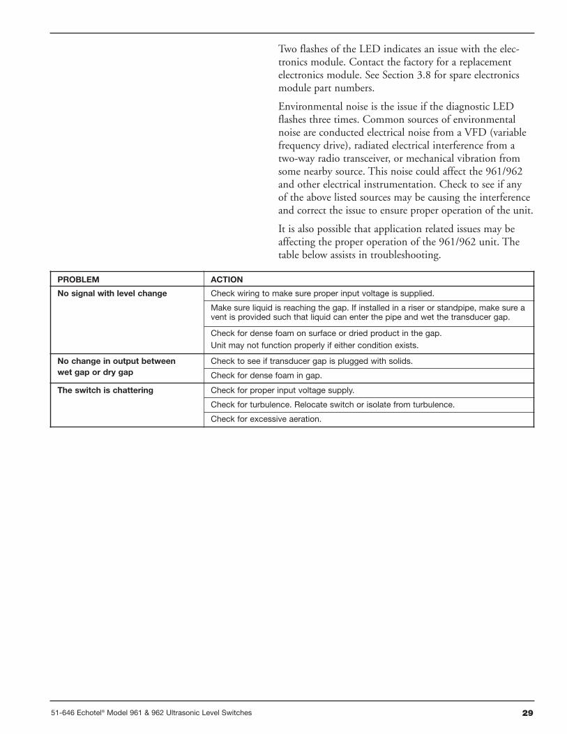
Two flashes of the LED indicates an issue with the elec-tronics module. Contact the factory for a replacementelectronics module. See Section 3.8 for spare electronicsmodule part numbers.
Environmental noise is the issue if the diagnostic LEDflashes three times. Common sources of environmentalnoise are conducted electrical noise from a VFD (variablefrequency drive), radiated electrical interference from atwo-way radio transceiver, or mechanical vibration fromsome nearby source. This noise could affect the 961/962and other electrical instrumentation. Check to see if anyof the above listed sources may be causing the interferenceand correct the issue to ensure proper operation of the unit.
It is also possible that application related issues may beaffecting the proper operation of the 961/962 unit. Thetable below assists in troubleshooting.
PROBLEM ACTION
No signal with level change Check wiring to make sure proper input voltage is supplied.
Make sure liquid is reaching the gap. If installed in a riser or standpipe, make sure avent is provided such that liquid can enter the pipe and wet the transducer gap.
Check for dense foam on surface or dried product in the gap.Unit may not function properly if either condition exists.
No change in output betweenwet gap or dry gap
Check to see if transducer gap is plugged with solids.
Check for dense foam in gap.
The switch is chattering Check for proper input voltage supply.
Check for turbulence. Relocate switch or isolate from turbulence.
Check for excessive aeration.
30 51-646 Echotel® Model 961 & 962 Ultrasonic Level Switches
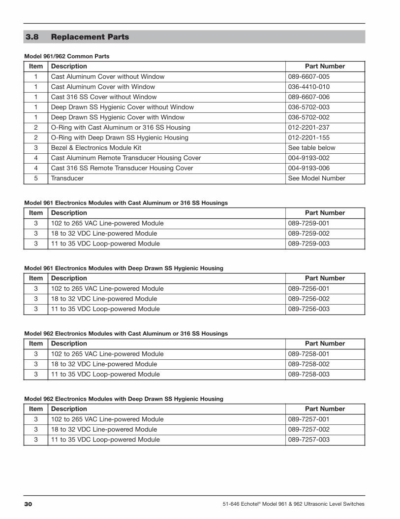
Model 961/962 Common Parts
3.8 Replacement Parts
Item Description Part Number
1 Cast Aluminum Cover without Window 089-6607-005
1 Cast Aluminum Cover with Window 036-4410-010
1 Cast 316 SS Cover without Window 089-6607-006
1 Deep Drawn SS Hygienic Cover without Window 036-5702-003
1 Deep Drawn SS Hygienic Cover with Window 036-5702-002
2 O-Ring with Cast Aluminum or 316 SS Housing 012-2201-237
2 O-Ring with Deep Drawn SS Hygienic Housing 012-2201-155
3 Bezel & Electronics Module Kit See table below
4 Cast Aluminum Remote Transducer Housing Cover 004-9193-002
4 Cast 316 SS Remote Transducer Housing Cover 004-9193-006
5 Transducer See Model Number
Model 961 Electronics Modules with Cast Aluminum or 316 SS Housings
Item Description Part Number
3 102 to 265 VAC Line-powered Module 089-7259-001
3 18 to 32 VDC Line-powered Module 089-7259-002
3 11 to 35 VDC Loop-powered Module 089-7259-003
Model 961 Electronics Modules with Deep Drawn SS Hygienic Housing
Item Description Part Number
3 102 to 265 VAC Line-powered Module 089-7256-001
3 18 to 32 VDC Line-powered Module 089-7256-002
3 11 to 35 VDC Loop-powered Module 089-7256-003
Model 962 Electronics Modules with Cast Aluminum or 316 SS Housings
Item Description Part Number
3 102 to 265 VAC Line-powered Module 089-7258-001
3 18 to 32 VDC Line-powered Module 089-7258-002
3 11 to 35 VDC Loop-powered Module 089-7258-003
Model 962 Electronics Modules with Deep Drawn SS Hygienic Housing
Item Description Part Number
3 102 to 265 VAC Line-powered Module 089-7257-001
3 18 to 32 VDC Line-powered Module 089-7257-002
3 11 to 35 VDC Loop-powered Module 089-7257-003
3151-646 Echotel® Model 961 & 962 Ultrasonic Level Switches
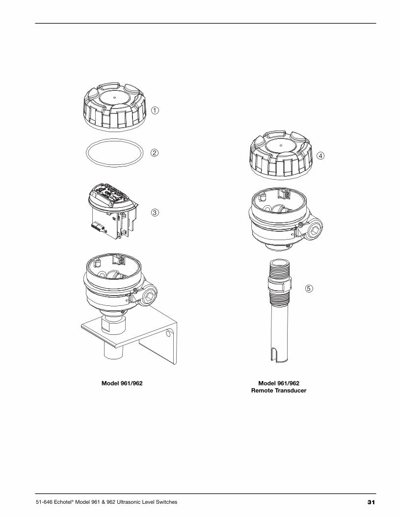
1
3
2 4
5
Model 961/962 Model 961/962Remote Transducer
32 51-646 Echotel® Model 961 & 962 Ultrasonic Level Switches
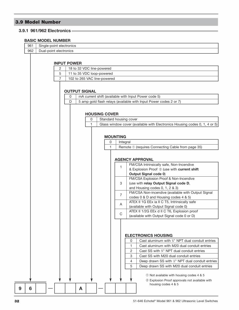
3.9 Model Number
3.9.1 961/962 Electronics
� Not available with housing codes 4 & 5
� Explosion Proof approvals not available withhousing codes 4 & 5
961 Single-point electronics962 Dual-point electronics
BASIC MODEL NUMBER
2 18 to 32 VDC line-powered5 11 to 35 VDC loop-powered7 102 to 265 VAC line-powered
INPUT POWER
0 mA current shift (available with Input Power code 5)D 5 amp gold flash relays (available with Input Power codes 2 or 7)
OUTPUT SIGNAL
0 Integral1 Remote � (requires Connecting Cable from page 35)
MOUNTING
1FM/CSA Intrinsically safe, Non-Incendive& Explosion Proof � (use with current shiftOutput Signal code 0)
3FM/CSA Explosion Proof & Non-Incendive(use with relay Output Signal code D,and Housing codes 0, 1, 2 & 3)
7FM/CSA Non-incendive (available with Output Signalcodes 0 & D and Housing codes 4 & 5)
AATEX II 1G EEx ia II C T5, Intrinsically safe(available with Output Signal code 0)
CATEX II 1/2G EEx d II C T6, Explosion proof(available with Output Signal code 0 or D)
AGENCY APPROVAL
0 Cast aluminum with 3⁄4" NPT dual conduit entries1 Cast aluminum with M20 dual conduit entries2 Cast SS with 3⁄4" NPT dual conduit entries3 Cast SS with M20 dual conduit entries4 Deep drawn SS with 1⁄2" NPT dual conduit entries5 Deep drawn SS with M20 dual conduit entries
ELECTRONICS HOUSING
9 6 A
0 Standard housing cover1 Glass window cover (available with Electronics Housing codes 0, 1, 4 or 5)
HOUSING COVER
3351-646 Echotel® Model 961 & 962 Ultrasonic Level Switches
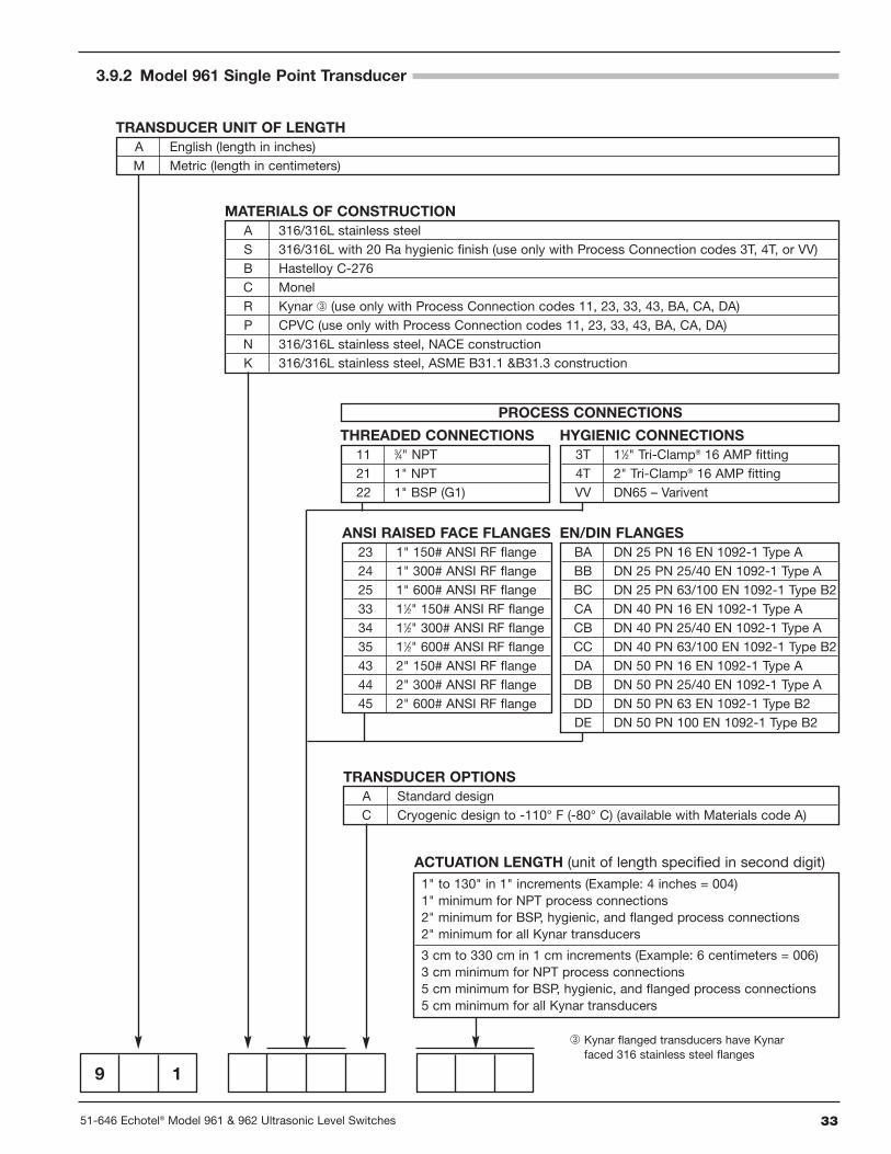
3.9.2 Model 961 Single Point Transducer
9 1
A English (length in inches)M Metric (length in centimeters)
TRANSDUCER UNIT OF LENGTH
A 316/316L stainless steelS 316/316L with 20 Ra hygienic finish (use only with Process Connection codes 3T, 4T, or VV)B Hastelloy C-276C MonelR Kynar � (use only with Process Connection codes 11, 23, 33, 43, BA, CA, DA)P CPVC (use only with Process Connection codes 11, 23, 33, 43, BA, CA, DA)N 316/316L stainless steel, NACE constructionK 316/316L stainless steel, ASME B31.1 &B31.3 construction
MATERIALS OF CONSTRUCTION
PROCESS CONNECTIONS
11 3⁄4" NPT21 1" NPT22 1" BSP (G1)
THREADED CONNECTIONS
23 1" 150# ANSI RF flange24 1" 300# ANSI RF flange25 1" 600# ANSI RF flange33 11⁄2" 150# ANSI RF flange34 11⁄2" 300# ANSI RF flange35 11⁄2" 600# ANSI RF flange43 2" 150# ANSI RF flange44 2" 300# ANSI RF flange45 2" 600# ANSI RF flange
ANSI RAISED FACE FLANGES
3T 11⁄2" Tri-Clamp® 16 AMP fitting4T 2" Tri-Clamp® 16 AMP fittingVV DN65 – Varivent
HYGIENIC CONNECTIONS
BA DN 25 PN 16 EN 1092-1 Type ABB DN 25 PN 25/40 EN 1092-1 Type ABC DN 25 PN 63/100 EN 1092-1 Type B2CA DN 40 PN 16 EN 1092-1 Type ACB DN 40 PN 25/40 EN 1092-1 Type ACC DN 40 PN 63/100 EN 1092-1 Type B2DA DN 50 PN 16 EN 1092-1 Type ADB DN 50 PN 25/40 EN 1092-1 Type ADD DN 50 PN 63 EN 1092-1 Type B2DE DN 50 PN 100 EN 1092-1 Type B2
EN/DIN FLANGES
� Kynar flanged transducers have Kynarfaced 316 stainless steel flanges
1" to 130" in 1" increments (Example: 4 inches = 004)1" minimum for NPT process connections2" minimum for BSP, hygienic, and flanged process connections2" minimum for all Kynar transducers
3 cm to 330 cm in 1 cm increments (Example: 6 centimeters = 006)3 cm minimum for NPT process connections5 cm minimum for BSP, hygienic, and flanged process connections5 cm minimum for all Kynar transducers
ACTUATION LENGTH (unit of length specified in second digit)
A Standard designC Cryogenic design to -110° F (-80° C) (available with Materials code A)
TRANSDUCER OPTIONS
34 51-646 Echotel® Model 961 & 962 Ultrasonic Level Switches
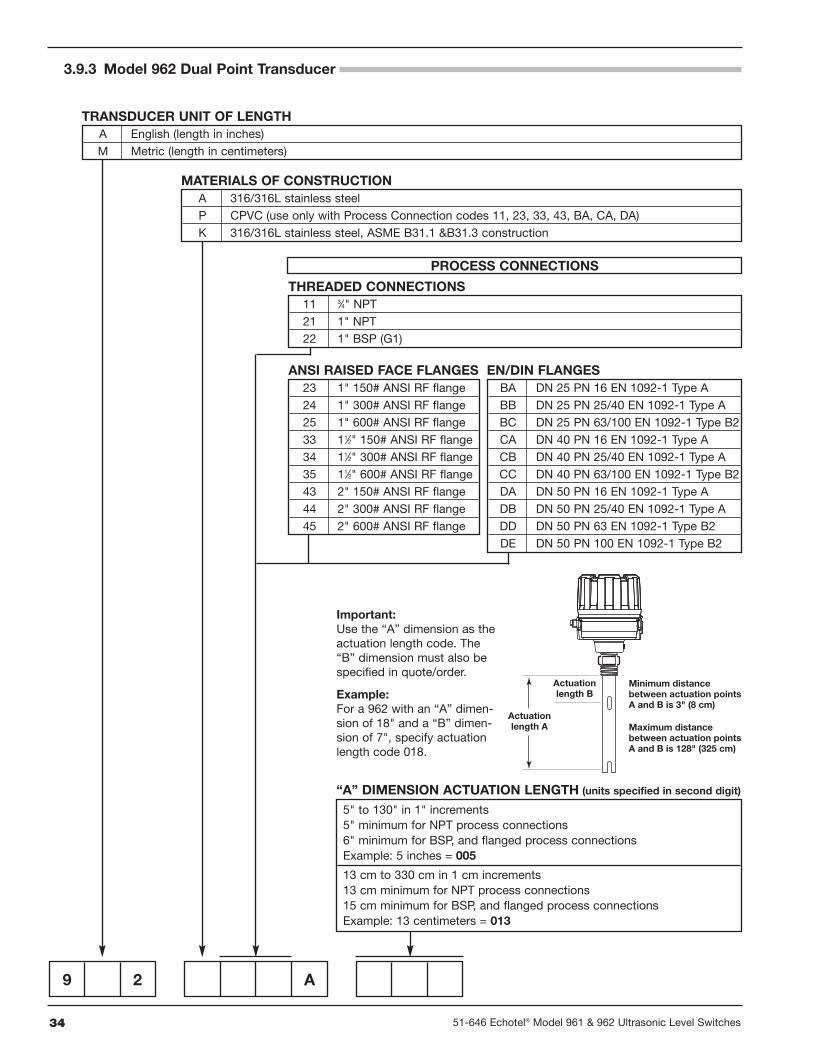
3.9.3 Model 962 Dual Point Transducer
9 2 A
A English (length in inches)M Metric (length in centimeters)
TRANSDUCER UNIT OF LENGTH
A 316/316L stainless steelP CPVC (use only with Process Connection codes 11, 23, 33, 43, BA, CA, DA)K 316/316L stainless steel, ASME B31.1 &B31.3 construction
MATERIALS OF CONSTRUCTION
11 3⁄4" NPT21 1" NPT22 1" BSP (G1)
THREADED CONNECTIONS
PROCESS CONNECTIONS
Actuationlength A
Minimum distancebetween actuation points A and B is 3" (8 cm)
Maximum distancebetween actuation points A and B is 128" (325 cm)
Actuationlength B
Important:Use the “A” dimension as theactuation length code. The“B” dimension must also bespecified in quote/order.
Example:For a 962 with an “A” dimen-sion of 18" and a “B” dimen-sion of 7", specify actuationlength code 018.
5" to 130" in 1" increments5" minimum for NPT process connections6" minimum for BSP, and flanged process connectionsExample: 5 inches = 005
13 cm to 330 cm in 1 cm increments13 cm minimum for NPT process connections15 cm minimum for BSP, and flanged process connectionsExample: 13 centimeters = 013
“A” DIMENSION ACTUATION LENGTH (units specified in second digit)
23 1" 150# ANSI RF flange24 1" 300# ANSI RF flange25 1" 600# ANSI RF flange33 11⁄2" 150# ANSI RF flange34 11⁄2" 300# ANSI RF flange35 11⁄2" 600# ANSI RF flange43 2" 150# ANSI RF flange44 2" 300# ANSI RF flange45 2" 600# ANSI RF flange
ANSI RAISED FACE FLANGESBA DN 25 PN 16 EN 1092-1 Type ABB DN 25 PN 25/40 EN 1092-1 Type ABC DN 25 PN 63/100 EN 1092-1 Type B2CA DN 40 PN 16 EN 1092-1 Type ACB DN 40 PN 25/40 EN 1092-1 Type ACC DN 40 PN 63/100 EN 1092-1 Type B2DA DN 50 PN 16 EN 1092-1 Type ADB DN 50 PN 25/40 EN 1092-1 Type ADD DN 50 PN 63 EN 1092-1 Type B2DE DN 50 PN 100 EN 1092-1 Type B2
EN/DIN FLANGES
3551-646 Echotel® Model 961 & 962 Ultrasonic Level Switches
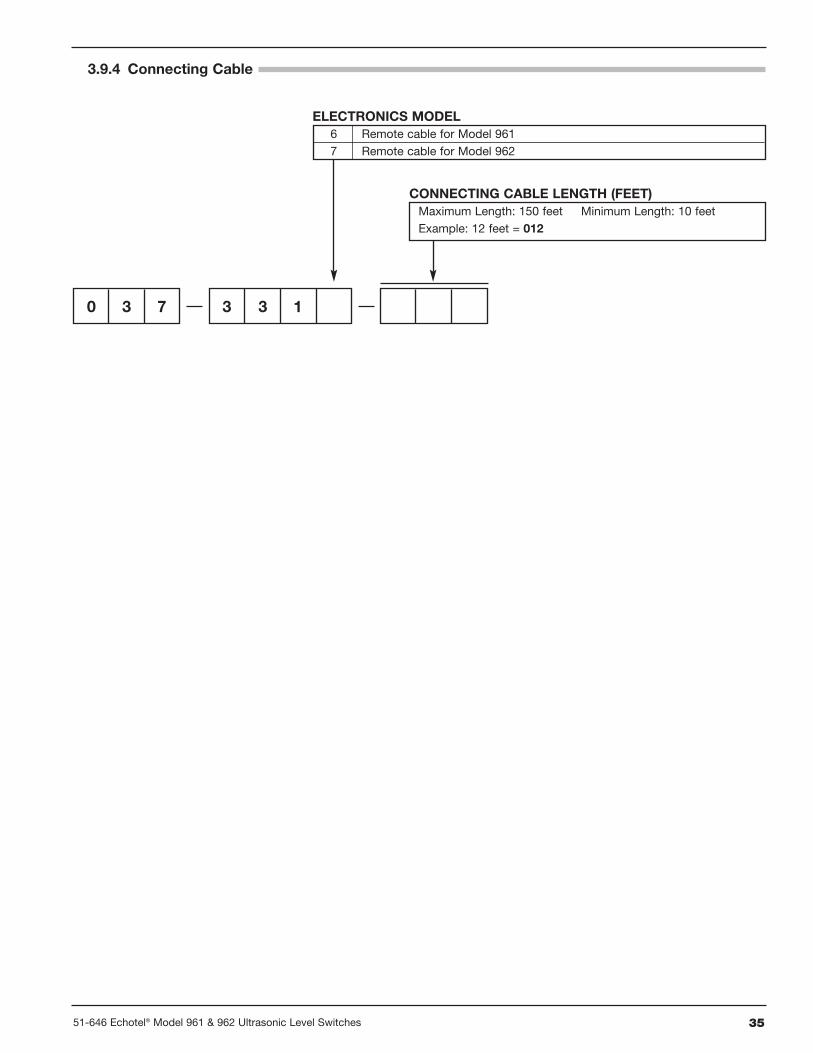
3.9.4 Connecting Cable
Maximum Length: 150 feet Minimum Length: 10 feetExample: 12 feet = 012
CONNECTING CABLE LENGTH (FEET)
0 3 7 3 3 1
6 Remote cable for Model 9617 Remote cable for Model 962
ELECTRONICS MODEL
BULLETIN: 51-646.2EFFECTIVE: June 2010SUPERCEDES: January 2009
5300 Belmont Road • Downers Grove, Illinois 60515-4499 • 630-969-4000 • Fax 630-969-9489 • www.magnetrol.com145 Jardin Drive, Units 1 & 2 • Concord, Ontario Canada L4K 1X7 • 905-738-9600 • Fax 905-738-1306Heikensstraat 6 • B 9240 Zele, Belgium • 052 45.11.11 • Fax 052 45.09.93Regent Business Ctr., Jubilee Rd. • Burgess Hill, Sussex RH15 9TL U.K. • 01444-871313 • Fax 01444-871317
Copyright © 2011 MAGNETROL INTERNATIONAL, INCORPORATED. All rights reserved. Printed in the USA.
Service Policy
Owners of MAGNETROL controls may request thereturn of a control or any part of a control for completerebuilding or replacement. They will be rebuilt or replacedpromptly. Controls returned under our service policy mustbe returned by Prepaid transportation. MAGNETROLwill repair or replace the control at no cost to the purchas-er (or owner) other than transportation if:
1. Returned within the warranty period; and2. The factory inspection finds the cause of the claim
to be covered under the warranty.
If the trouble is the result of conditions beyond our con-trol; or, is NOT covered by the warranty, there will becharges for labor and the parts required to rebuild orreplace the equipment.
In some cases it may be expedient to ship replacementparts; or, in extreme cases a complete new control, toreplace the original equipment before it is returned. Ifthis is desired, notify the factory of both the model andserial numbers of the control to be replaced. In suchcases, credit for the materials returned will be determinedon the basis of the applicability of our warranty.
No claims for misapplication, labor, direct or consequen-tial damage will be allowed.
Return Material Procedure
So that we may efficiently process any materials that arereturned, it is essential that a “Return MaterialAuthorization” (RMA) number be obtained from the fac-tory, prior to the material’s return. This is available througha MAGNETROL local representative or by contacting thefactory. Please supply the following information:
1. Company Name2. Description of Material3. Serial Number4. Reason for Return5. Application
Any unit that was used in a process must be properlycleaned in accordance with OSHA standards, before it isreturned to the factory.
A Material Safety Data Sheet (MSDS) must accompanymaterial that was used in any media.
All shipments returned to the factory must be by prepaidtransportation.
All replacements will be shipped F.O.B. factory.
NOTE: See Electrostatic Discharge Handling Procedureon page 5.
ASSURED QUALITY & SERVICE COST LESS
MAGNETROL, MAGNETROL logotype and ECHOTEL are registered trademarks of MAGNETROL INTERNATIONAL, INCORPORATED.Kynar® is a registered trademark of Elf Atochem North America, Inc.Hastelloy® is a registered trademark of HAYNES INTERNATIONAL, INC. (DELAWARE CORPORATION).Monel® is a registered trademark of the INCO family of companies.