Embed Size (px)
Citation preview
Fatigue Properties of a S45C Steel Subjected with
Ultrasonic Nano-crystal Surface Modification
Ri-ichi Murakami
The University of Tokushima, Dept. of Mechanical Engineering,2-1 Minami-josanjima-cho, Tokushima, 770-8506 Japan

2
An-AC
A
n-X
③
Hybrid nanocrystalline
Based on ②
Background
B
A
A
n-B
Coating and deposition
①
PVDCVDElectroplatingElectrodeposition……
A
An-A
②
Surface self-nanocrystalline
Shot peeningWater peeningRoller burnishingLaser shock peeningUltrasonic nano-crystal surface modificationNonequilibrium thermodynamics ……
Methods to achieve nano-crystal surface layer
3
100µm100µm
dd
AfterBefore
Machining direction
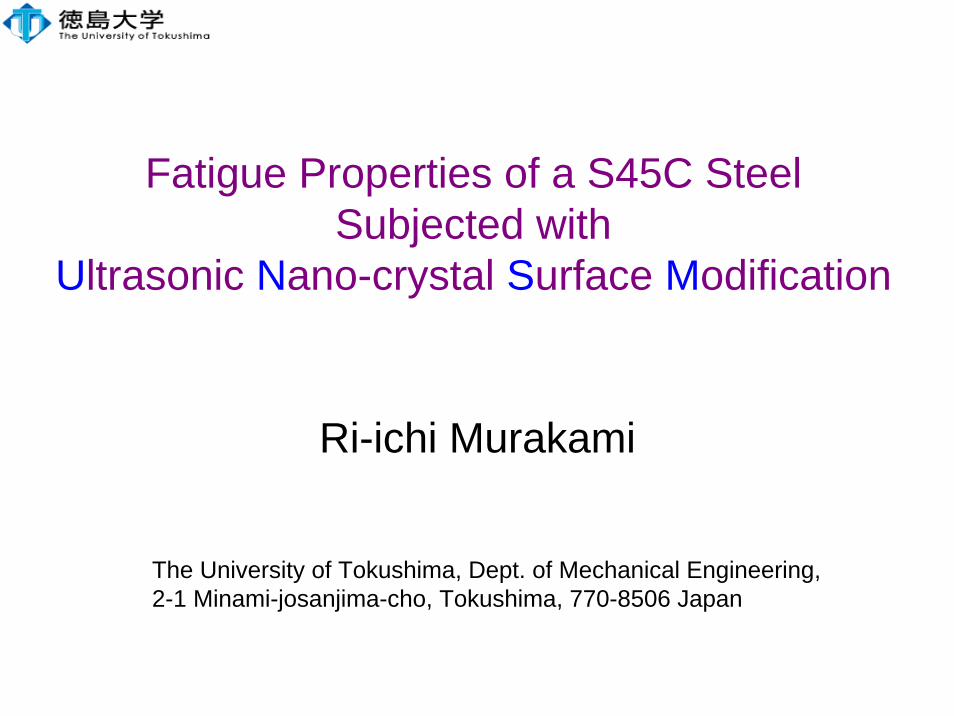
Fig. 1(a) TEM image shows surface layers as an amorphism(b) Microstructures “before” and “after” UNSM treatment
Size of crystal structure on surface layer
After50~200 nm
Before20 µm
Depth of deformed nano surface 100 µm
(a) (b)
Deformation of crystal structure
SKD61
4
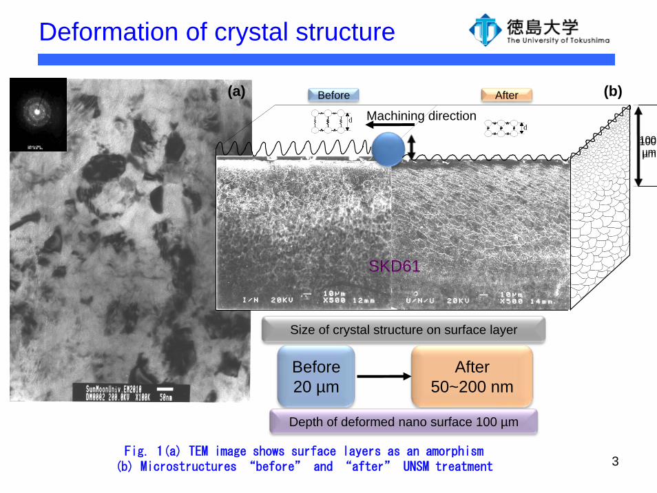
Comparison
Tech. vs. Character SP LSP LPB, DR USP UNSM
Energy source Powder injection Laser heat Static load
Ultrasonic dynamic
load
Static load + Ultrasonic
dynamic load
Compressive residual stress/depth 1 5 4 2 4
Hardness & depth 1 4 3 2 5
Nano structure 2 1 3 4 5
Surface topology 2 5 1 3 4
Surface Roughness 2 1 4 3 5
SP: Shot Peening, LSP: Laser Shock peening, LPB : Low Plasticity Burnishing, DR: Deep Rolling, USP : Ultrasonic Shot Peening, UNSM: Ultrasonic Nanocrystal Surface Modification
Effect of various peening technologies on mechanical properties
5: Best
~1: Worst
5
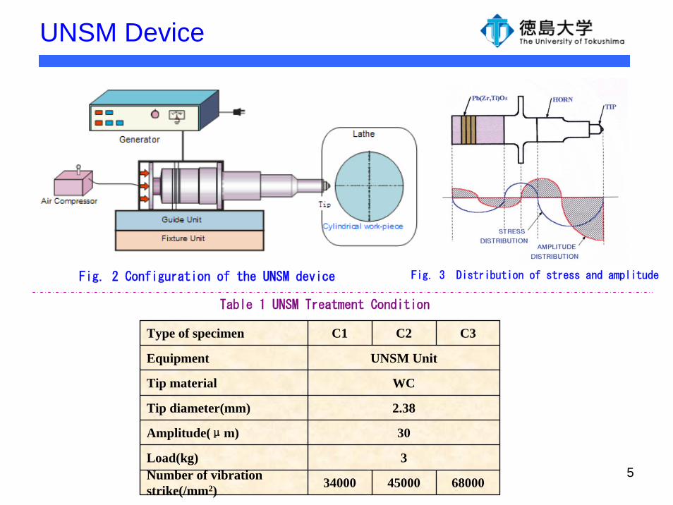
UNSM Device
Fig. 2 Configuration of the UNSM device Fig. 3 Distribution of stress and amplitude
680004500034000Number of vibration strike(/mm2)
3Load(kg)
30Amplitude(μm)
2.38Tip diameter(mm)
WCTip material
UNSM UnitEquipment
C3C2C1Type of specimen
Table 1 UNSM Treatment Condition
6
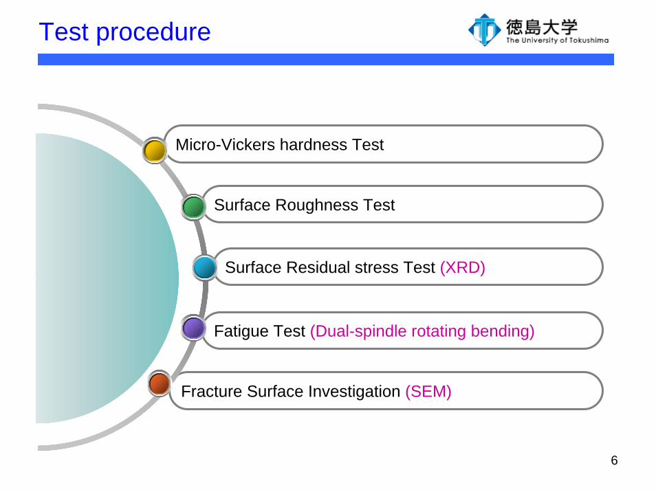
Test procedure
Fracture Surface Investigation (SEM)
Fatigue Test (Dual-spindle rotating bending)
Surface Residual stress Test (XRD)
Surface Roughness Test
Micro-Vickers hardness Test
7
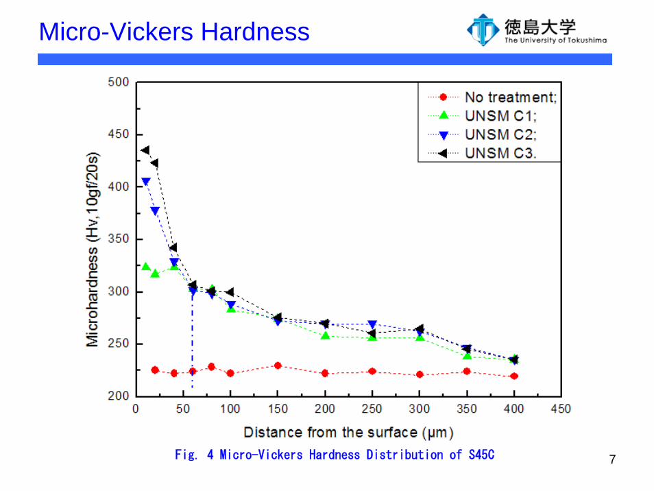
Micro-Vickers Hardness
Fig. 4 Micro-Vickers Hardness Distribution of S45C
8
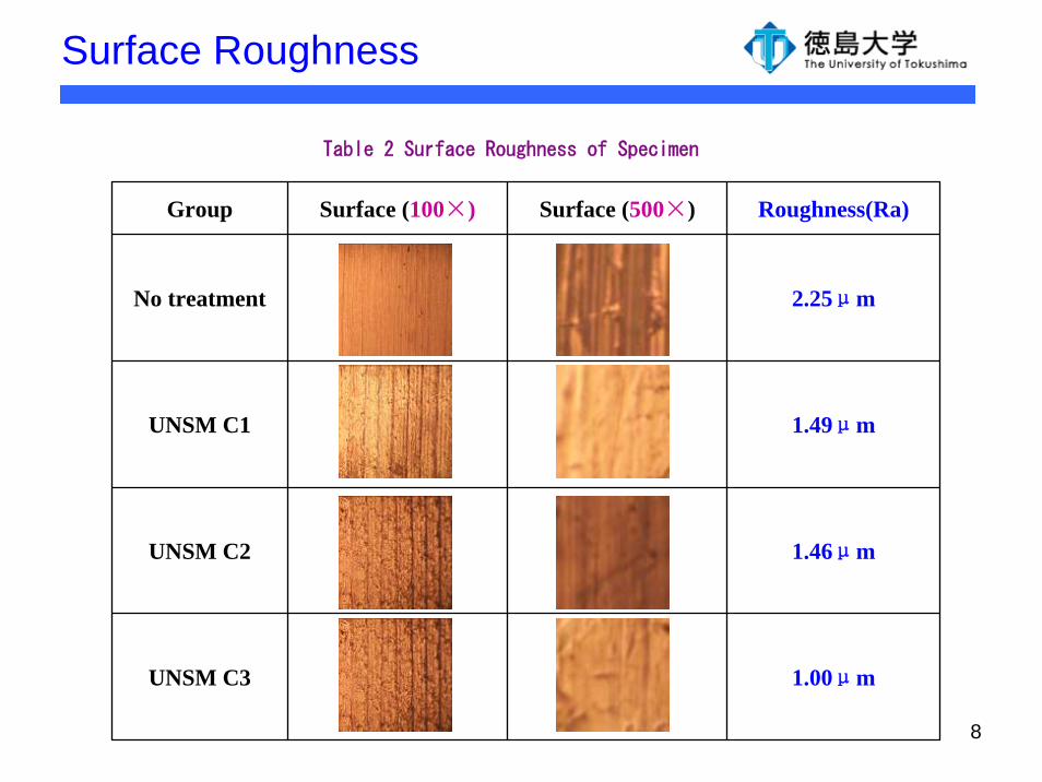
Surface Roughness
Table 2 Surface Roughness of Specimen
Group Surface (100×) Surface (500×) Roughness(Ra)
No treatment 2.25μm
UNSM C1 1.49μm
UNSM C2 1.46μm
UNSM C3 1.00μm
9
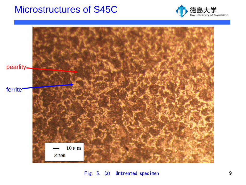
Microstructures of S45C
pearlity
ferrite
Fig. 5. (a) Untreated specimen
10
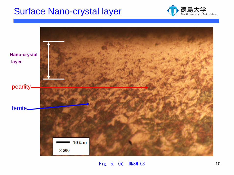
Surface Nano-crystal layer
pearlity
ferrite
Fig. 5. (b) UNSM C3
Nano-crystallayer
11
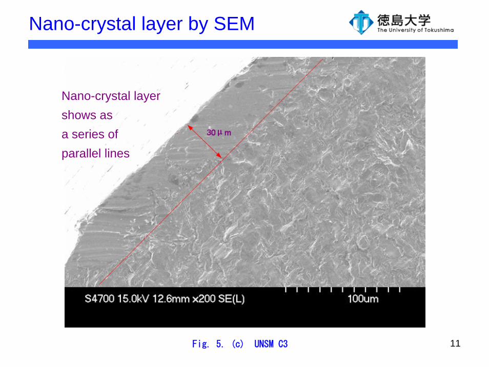
Nano-crystal layer by SEM
Fig. 5. (c) UNSM C3
Nano-crystal layershows as a series ofparallel lines
12
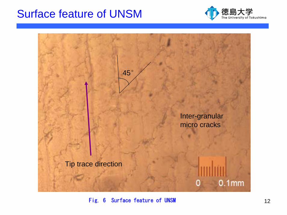
Surface feature of UNSM
Fig. 6 Surface feature of UNSM
Tip trace direction
45°
Inter-granular micro cracks
13
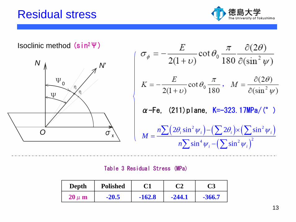
Residual stress
Table 3 Residual Stress (MPa)
Depth Polished C1 C2 C3
20μm -20.5 -162.8 -244.1 -366.7
α-Fe, (211)plane, K=-323.17MPa/(°)
( ) ( ) ( )( )
2 2
24 2
2 sin 2 sin
sin sini i i i
i i
nM
n
θ ψ θ ψ
ψ ψ
− ×=
−
∑ ∑ ∑∑ ∑
Isoclinic method (sin2Ψ)
N N’
O σx
Ψ0
Ψηη
14
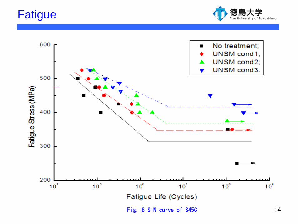
Fatigue
Fig. 8 S-N curve of S45C
15
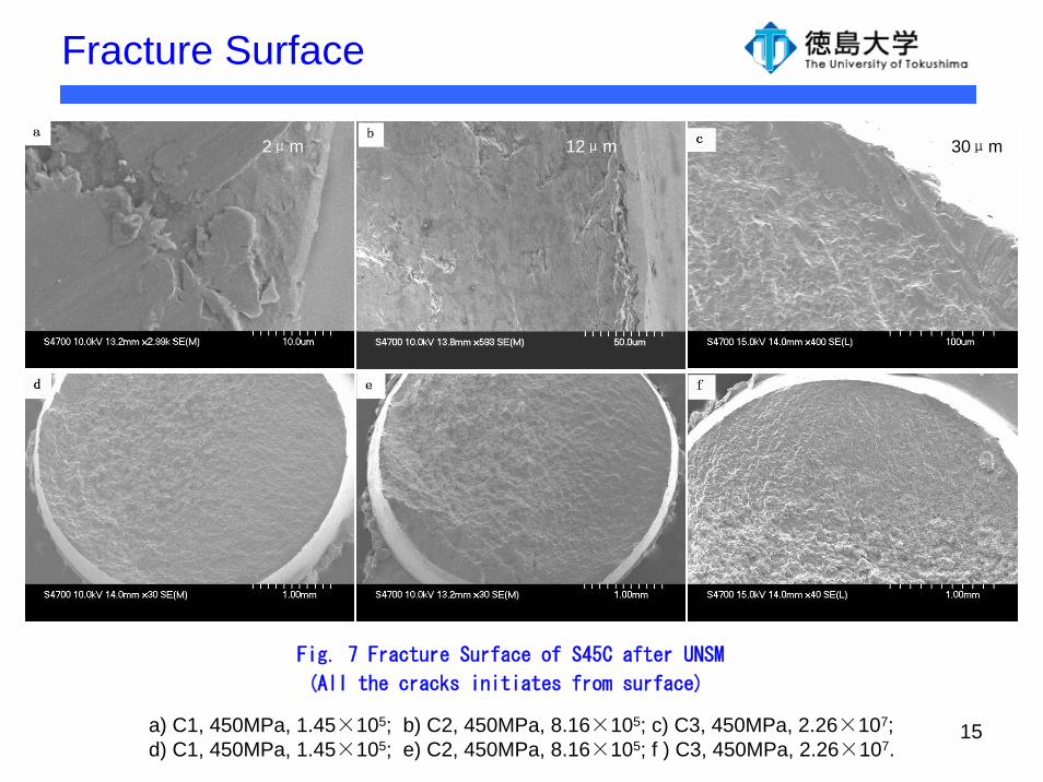
Fracture Surface
Fig. 7 Fracture Surface of S45C after UNSM
(All the cracks initiates from surface)
a) C1, 450MPa, 1.45×10⁵; b) C2, 450MPa, 8.16×10⁵; c) C3, 450MPa, 2.26×10⁷; d) C1, 450MPa, 1.45×10⁵; e) C2, 450MPa, 8.16×10⁵; f ) C3, 450MPa, 2.26×10⁷.
2μm 12μm 30μm
16
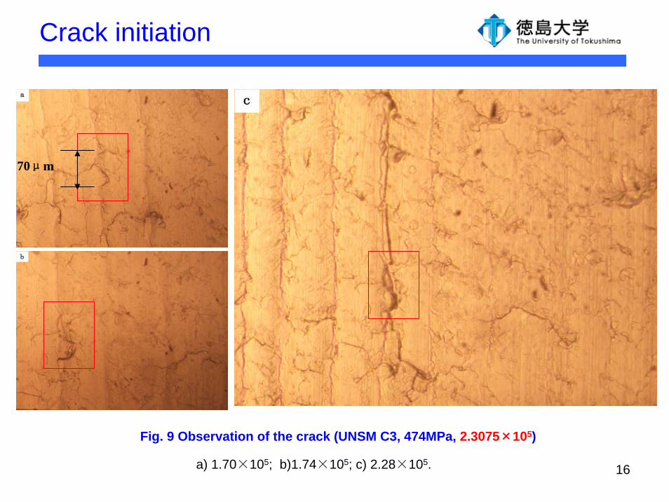
Crack initiation
Fig. 9 Observation of the crack (UNSM C3, 474MPa, 2.3075×10⁵)
a) 1.70×10⁵; b)1.74×10⁵; c) 2.28×10⁵.
70μm
17
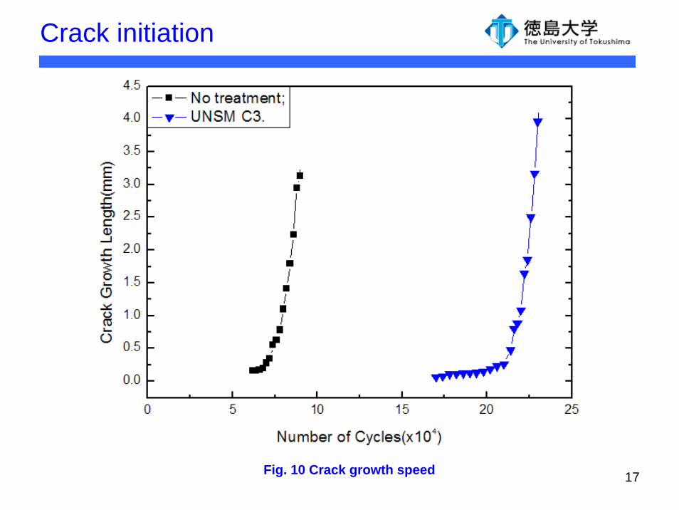
Crack initiation
Fig. 10 Crack growth speed
18
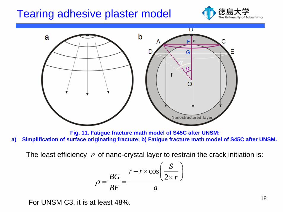
Tearing adhesive plaster model
cos2
Sr rBG rBF a
ρ
⎛ ⎞− × ⎜ ⎟×⎝ ⎠= =
The least efficiency ρ of nano-crystal layer to restrain the crack initiation is:
For UNSM C3, it is at least 48%.
Fig. 11. Fatigue fracture math model of S45C after UNSM:a) Simplification of surface originating fracture; b) Fatigue fracture math model of S45C after UNSM.
r
19
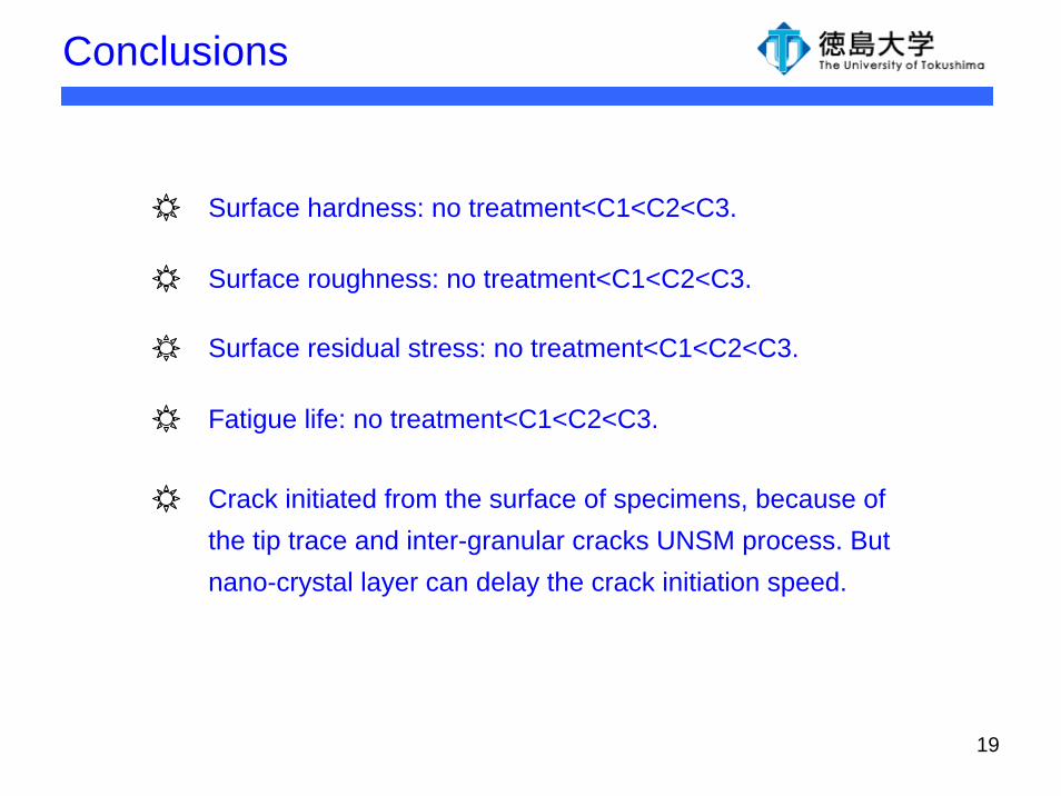
Conclusions
Surface hardness: no treatment<C1<C2<C3.
Surface roughness: no treatment<C1<C2<C3.
Surface residual stress: no treatment<C1<C2<C3.
Fatigue life: no treatment<C1<C2<C3.
Crack initiated from the surface of specimens, because of the tip trace and inter-granular cracks UNSM process. But nano-crystal layer can delay the crack initiation speed.
20