Embed Size (px)
Citation preview

Parts List:Please identify and verify that you have all of the
hardware shown below prior to assembly.
Parts listed below are not shown in the hardware drawings. Refer to photos in the instructions:
Part Description Quantity525B SledBase . . . . . . . . . . . . . . . . . . . . . . . . . 1525A PhenolicSub-Fence . . . . . . . . . . . . . . . . 14424 24”UltraTrackFence . . . . . . . . . . . . . . 14912B 11-3/4”JigBar . . . . . . . . . . . . . . . . . . . . . 16305IC InboardClamp . . . . . . . . . . . . . . . . . . . . 26305OC OutboardClamp . . . . . . . . . . . . . . . . . . 1
525 Large Coping Sled
Please Read Carefully!
Part# Description Qty.5760B OvalNut 7
Part# Description Qty.MF040 3/4"Screw 2
Part# Description Qty.BUSH004 5/8”Spacer 4
Part# Description Qty.MF010 3/4”Screw 3
Part# Description Qty.STP001 3/4”Screw 4
Part# Description Qty.HB030 1”Bolt 1
Part# Description Qty.HB040 1-1/4”Bolt 3
Part# Description Qty.5860 RatchetHandle 2
Part# Description Qty.5590 Knob 2
Part# Description Qty.MF006 5/8”Screw 4
BEFORE BEGINNING: Identifyandverifythatyouhaveallthepartslisted.Readtheinstructionsatleastonce,familiarizingyourselfwiththepartsbeforeassembly.
You’llneeda#2Phillipsscrewdriver.TheCopingSledcanbeusedonashaper,oraroutertablewith,orwithout,amiterslot.

1
IfusingtheJigBar(4912B),followtheinstructionsthatcomewithit.Afteradjustingthebartofityourmiterslot,attachthebartothebase(525B) usingtwoofthemountingholesinthebase.
Determinewhereonthebaseyouwishtoattachthe24”UltraTrackFence(4424).ThepositionoftheUltraTrackFenceonthebasewillaffectthemaximumwidthofstockthatcanbeused.ThisdrawingdepictstheUltraTrackFencelocatedasfarforwardonthebaseaspossibleandwilllimitthemaximumstockwidthyoucanuseto10-3/8”.Byusingoneoftheothertwomountingpositionsyoucanincreasethiswidthby3/4”(11-1/8”capacity)or1-1/2”(11-7/8”capacity).
Inserta3/4”screw(MF010)throughthethreeselectedcountersunkholesinthebase.Startanovalnut(5760B - smooth side first)ontheendsofthescrewsandslidetheUltraTrackFenceontheovalnuts.CheckthattheUltraTrackFenceissquaretothebase.
IfusingaMiterBar,positiontheendoftheUltraTrackFenceflushwiththeinboardedgeofthebaseasillustrated.
Selectmountingholesthatpositionthebaseascloseaspossibletothecutterwith
outstrikingit.Usethetwo3/4”screws(MF040)toattachthebartothebaseinstead
of the screws that come with the bar.
IfnotusingaMiterBar,positiontheendoftheUltraTrackFence1/2”infromtheedgeofthebase,
orfarenoughinfromtheedgesothecutterwon’tstrikeit.
MF040 x2
5760B x3 MF010 x3
4912B: Jig Bar
525B:
Coping Sled Base
4424: Ultra Track
2
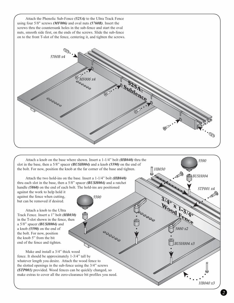
AttachthePhenolicSub-Fence(525A)totheUltraTrackFenceusingfour5/8"screws(MF006)andovalnuts(5760B).Insertthescrewsthruthecountersunkholesinthesub-fenceandstarttheovalnuts,smoothsidefirst,ontheendsofthescrews.Slidethesub-fenceontothefrontT-slotofthefence,centeringit,andtightenthescrews.
Attachaknobonthebasewhereshown.Inserta1-1/4”bolt(HB040)thrutheslotinthebase,thena5/8”spacer(BUSH004)andaknob(5590)ontheendofthebolt.Fornow,positiontheknobatthefarcornerofthebaseandtighten.
Attachthetwohold-insonthebase.Inserta1-1/4”bolt(HB040) thrueachslotinthebase,thena5/8”spacer(BUSH004)andaratchethandle(5860)ontheendofeachbolt.Thehold-insarepositionedagainsttheworktohelpholditagainstthefencewhencutting,butcanberemovedifdesired.
AttachaknobtotheUltraTrackFence.Inserta1”bolt(HB030)intheT-slotshowninthefence,thena5/8”spacer(BUSH004)andaknob(5590)ontheendofthebolt.Fornow,positiontheknob5”fromthebitendofthefenceandtighten.
Makeandinstalla3/4”thickwoodfence.Itshouldbeapproximately1-3/4”tallbywhateverlengthyoudesire.Attachthewoodfencetotheslottedopeningsinthesub-fenceusingthe3/4”screws(STP001)provided.Woodfencescanbequicklychanged,somakeextrastocoverallthezero-clearancebitprofilesyouneed.
5760B x4
525A: Subfence
3/4” x 1-3/4”
Wood Fence
MF006 x4
HB030
HB040 x3
5860 x2
BUSH004 x3
5590
5590
BUSH004
STP001 x4
3
ASSEMBLE CLAMPS AssemblethetwoInboardClamps(6305IC)andtheOutboardClamp(6305OC)accordingtothedirectionsincluded.Fornow,attachoneInboardClampateachendofthefencewhereshown.
INSTALL CUTTER Installtherouterbit/cutterinyourrouterorshaper.Adjustthebitheight,takingintoaccountthe1/2”thicknessofthebase.Weuseanextrathickbasetoinsurethatthere’snodistortiontothebasewhenyouusethetoggleclamp.Mostcopebitsandrouterswillworkwiththissled,but
makesureyouhaveatleast3/4”to1”oftherouterbitshankintherouterbeforemakinganycuts.Ifextrabitheightisneeded,youmayneedtouseacolletextension.Makesurethebit/cutterwillnotstriketheUltraTrackfence!
OPTIONAL ACCESSORIES The6305R 1” Riser Kit(oneperclamprequired)increasestheclampcapacityby1”.The525S Flip Stopprovidesanadjustableworkstop.
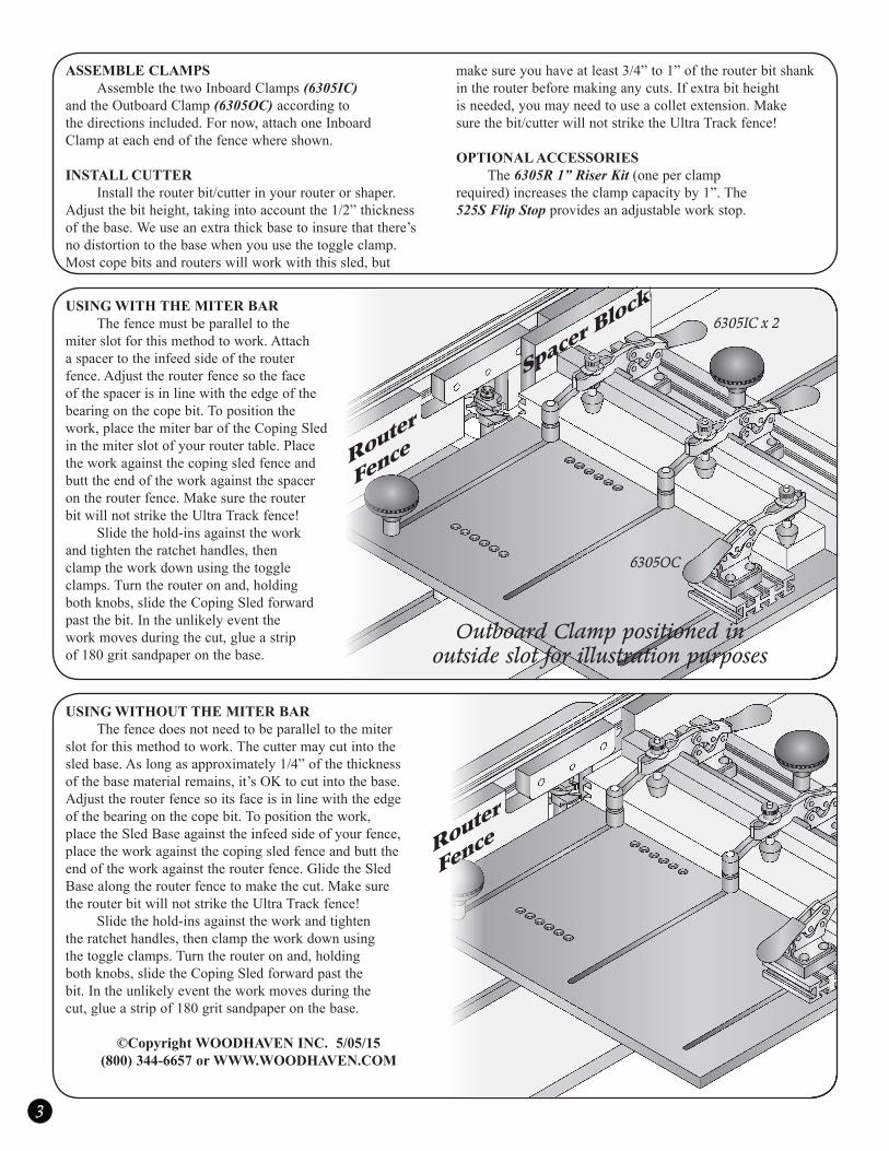
USING WITH THE MITER BAR Thefencemustbeparalleltothemiterslotforthismethodtowork.Attachaspacertotheinfeedsideoftherouterfence.Adjusttherouterfencesothefaceofthespacerisinlinewiththeedgeofthebearingonthecopebit.Topositionthework,placethemiterbaroftheCopingSledinthemiterslotofyourroutertable.Placetheworkagainstthecopingsledfenceandbutttheendoftheworkagainstthespacerontherouterfence.MakesuretherouterbitwillnotstriketheUltraTrackfence! Slidethehold-insagainsttheworkandtightentheratchethandles,thenclamptheworkdownusingthetoggleclamps.Turntherouteronand,holdingbothknobs,slidetheCopingSledforwardpastthebit.Intheunlikelyeventtheworkmovesduringthecut,glueastripof180gritsandpaperonthebase.
USING WITHOUT THE MITER BAR Thefencedoesnotneedtobeparalleltothemiterslotforthismethodtowork.Thecuttermaycutintothesledbase.Aslongasapproximately1/4”ofthethicknessofthebasematerialremains,it’sOKtocutintothebase. Adjusttherouterfencesoitsfaceisinlinewiththeedgeofthebearingonthecopebit.Topositionthework,placetheSledBaseagainsttheinfeedsideofyourfence,placetheworkagainstthecopingsledfenceandbutttheendoftheworkagainsttherouterfence.GlidetheSledBasealongtherouterfencetomakethecut.MakesuretherouterbitwillnotstriketheUltraTrackfence! Slidethehold-insagainsttheworkandtightentheratchethandles,thenclamptheworkdownusingthetoggleclamps.Turntherouteronand,holdingbothknobs,slidetheCopingSledforwardpastthebit.Intheunlikelyeventtheworkmovesduringthecut,glueastripof180gritsandpaperonthebase.
©Copyright WOODHAVEN INC. 5/05/15(800) 344-6657 or WWW.WOODHAVEN.COM
Spacer Block
Router
Fence
Router
Fence
Outboard Clamp positioned in outside slot for illustration purposes
6305IC x 2
6305OC