Embed Size (px)
Citation preview
Kansas Department of Transportation Bridge Construction Manual
5.3 DRIVEN PILE Table of Contents
5.3 DRIVEN PILE ........................................................................................................................15.3.1 General ..................................................................................................................1
5.3.2 Bid Items ....................................................................................................................15.3.3. Types of Piles .......................................................................................................85.3.4 Pile Driving Equipment .......................................................................................11
5.3.4.1 Pile Leads: ...............................................................................................................115.3.4.2 Pile Cap (Helmet): ...................................................................................................115.3.4.3 Types of Hammers: ................................................................................................125.3.4.4 Power for Hammers: ..............................................................................................155.3.4.5 Diesel Hammer Terminology: ................................................................................15
5.3.5 KDOT Specifications for Hammer Sizes: ...........................................................175.3.6 Pile Driving Mechanics: ......................................................................................18
5.3.6.1 Reviewing the Information on the Plans: ................................................................195.3.6.2 Preparing to Drive Pile ............................................................................................205.3.6.3 During the Drive ......................................................................................................215.3.3.1 Basis of Acceptance (Materials) .............................................................................105.3.3.2 Pile Order Lengths ..................................................................................................10
5.3.7 Pile Restrike .......................................................................................................265.3.8 Log of Pile Driving .............................................................................................29
5.3.8.1 As-Built Geology ....................................................................................................365.3.8.2 Pile Driving Formulas ............................................................................................395.3.8.3 Field Pile Driving Guide .........................................................................................40
5.3.9 Hammer Data ......................................................................................................42
List of FiguresFigure 1 Pile Splice Location Limits ..............................................................................................5Figure 2 Bridge Standard BR110 Pile Splice Details .....................................................................6Figure 3 Pile Points .........................................................................................................................9Figure 4 Pipe .................................................................................................................................10Figure 5 Plumbing an H-Pile ........................................................................................................22Figure 6 Measuring Rotation of a Pile ..........................................................................................23Figure 7 Mark pile as Driving Continues .....................................................................................25Figure 8 Mark After Specified Blows ...........................................................................................25Figure 9 Measure Displacement ...................................................................................................25Figure 10 Continue Driving Until Bearing ...................................................................................25Figure 11 Continuous Log Example .............................................................................................35Figure 12Form 217B General Information Sheet .........................................................................41Figure 13Form 217B Delmag Sheet Example ..............................................................................42
Version 5/13 KDOT Bridge Section 5.3 - Driven Pile - 1
Kansas Department of Transportation Bridge Construction Manual
List of TablesTable 1 for Rotated Pile ................................................................................................................24Table 2 for Rotated Pile ................................................................................................................24
Version 5/13 KDOT Bridge Section 5.3 - Driven Pile - 2
Kansas Department of Transportation Bridge Construction Manual
Disclaimer: This website and documents are provided for use by persons outside of the Kansas Department of Transportation as
information only. The Kansas Department of Transportation, the State of Kansas, nor its officers or employees, by making this
website and documents available for use by persons outside of KDOT, does not undertake any duties or responsibilities of any such
person or entity who chooses to use this website and documents. This website and documents should not be substituted for the
exercise of a person�s own professional judgment nor the determination by contractors of the appropriate manner and method of
construction on projects under their control. It is the user�s obligation to make sure that he/she uses the appropriate practices. Any
person using this website and documents agrees that KDOT will not be liable for any commercial loss; inconvenience; loss of use,
time, data, goodwill, revenues, profits, or savings; or any other special, incidental, indirect, or consequential damages in any way
related to or arising from use of this website and documents.
.
Version 5/13 KDOT Bridge Section 5.3 - Driven Pile - 3
Kansas Department of Transportation Bridge Construction Manual
Version 5/13 KDOT Bridge Section 5.3 - Driven Pile - 4
Kansas Department of Transportation Bridge Construction Manual
5.3 DRIVEN PILE
5.3.1 GeneralDriven piles are used as the foundation for almost all abutments in Kansas bridges. Likewise they are used as the foundation for many piers in Kansas bridges. Proper pile driving inspection is critical to a successful bridge project.
What is a driven pile?There are two types of driven piles: sheet pile and foundation pile. Sheet piles are long, interlocking, rolled steel plates used in retaining structures, such as walls and cofferdams. Foundation piles are long slender columns designed to be driven into the ground. Foundation piles will be discussed here.Foundation piles are simply columns, designed to transmit surface loads to low lying soil or bedrock. These loads are transmitted by friction between the pile and ground and by point bearing through the end of the pile. The actual amount of frictional resistance or end bearing is dependent on the particular site conditions.Foundation piles are made of steel, concrete, or timber. Of these materials, steel H-pile and cast-in-place pipe pile are most commonly used in Kansas. The material and size of pile to be used on a particular project are designated in the plans on the General Notes and Summary of Quantities Sheet.
Piles are used when a deep foundation is necessary. This is the case when the soil near the surface is unsuitable to carry the loads imposed by the structure. Piles are also used when the possibility exists that the soil under the foundation may be washed away.
5.3.2 Bid ItemsThe following is an abbreviated list and brief description of the bid items related to pile foundations. The entire list can be found in the Standard Specifications.
Test Pile:There are some instances in which the length of pile cannot be determined accurately by means of a soils boring or sounding. This is usually the case when friction pile or bearing pile is used where the geologic formation is weathered. In these instances a test pile will be required. A test pile is a single pile driven to determine the required length of the remaining pile for that foundation element. The test pile location will be shown on the plans. Usually there will be one test pile per bent location. These are ultimately used as production piles so the location tolerance is the same as a production pile. If the production piles are to be pre-drilled then the test pile is pre-drilled to the same depth.
With all the hammer information known, use the appropriate dynamic pile driving equation to compute the blow count (average) for the specified driving load and 110% of this value. The value for over driving the pile was 150% when Allowable Stress Design was used to determine the soil and pile resistance. As the Geology Section has moved into the realm of Load and
Version 5/13 KDOT Bridge Section 5.3 -Driven Pile - 1
Kansas Department of Transportation Bridge Construction Manual
Resistance Factor Design, the limits have been reduced on overdriving the pile. The hammer selected for the particular job should be rated to yield at least this value at the required resistance. Required resistance is 1/4” per 5 blows as the average of the last 20 blows for power driven hammers and the last 5 blows for gravity hammers.
After the pile penetrates the soft upper layers (about 6 feet) the blow count will be taken for each twelve inches of penetration. Mark the pile in twelve inch intervals prior to placing the pile in the leads and count the blows as the marks pass a fixed point. Record the average penetration in decimal inches by dividing twelve inches by the number of blows between the marks.
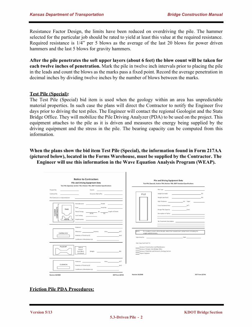
Test Pile (Special):The Test Pile (Special) bid item is used when the geology within an area has unpredictable material properties. In such case the plans will direct the Contractor to notify the Engineer five days prior to driving the test piles. The Engineer will contact the regional Geologist and the State Bridge Office. They will mobilize the Pile Driving Analyzer (PDA) to be used on the project. This equipment attaches to the pile as it is driven and measures the energy being supplied by the driving equipment and the stress in the pile. The bearing capacity can be computed from this information.
When the plans show the bid item Test Pile (Special), the information found in Form 217AA (pictured below), located in the Forms Warehouse, must be supplied by the Contractor. The
Engineer will use this information in the Wave Equation Analysis Program (WEAP).
Friction Pile PDA Procedures:
Version 5/13 KDOT Bridge Section 5.3-Driven Pile - 2
Kansas Department of Transportation Bridge Construction Manual
Currently plan specified pile driving values include Design Load, Allowable Load, and the General Note that specifies what “allowable” load to drive the pile to at each substructure element. Friction Pile are typically driven in western Kansas since there are no thick bedrock layers to seat a bearing pile into. From a practical standpoint it can be difficult to determine a required pile length with current technology. This is why a PDA is used on these projects to determine the length of pile required, the pile tip elevations, and various other values to allow inspectors to complete the rest of the pile using the equations in the specifications.
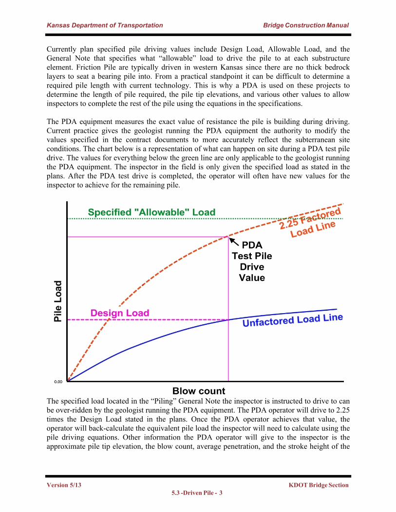
The PDA equipment measures the exact value of resistance the pile is building during driving. Current practice gives the geologist running the PDA equipment the authority to modify the values specified in the contract documents to more accurately reflect the subterranean site conditions. The chart below is a representation of what can happen on site during a PDA test pile drive. The values for everything below the green line are only applicable to the geologist running the PDA equipment. The inspector in the field is only given the specified load as stated in the plans. After the PDA test drive is completed, the operator will often have new values for the inspector to achieve for the remaining pile.
The specified load located in the “Piling” General Note the inspector is instructed to drive to can be over-ridden by the geologist running the PDA equipment. The PDA operator will drive to 2.25 times the Design Load stated in the plans. Once the PDA operator achieves that value, the operator will back-calculate the equivalent pile load the inspector will need to calculate using the pile driving equations. Other information the PDA operator will give to the inspector is the approximate pile tip elevation, the blow count, average penetration, and the stroke height of the
Version 5/13 KDOT Bridge Section 5.3 -Driven Pile - 3
Kansas Department of Transportation Bridge Construction Manual
hammer. The pile driving will proceed using the new values the PDA equipment has determined.Cut-Off and Splice:Pile cut-off and pile splicing are paid for as a function of the bid price for piling per linear foot.
Cut-OffThe Contractor will have enough of the pile sticking out of the ground for the proper cut off leaving a fresh heading and squared end. The penetration of the pile within an abutment or footing is shown on the plans and is critical to the structural continuity. As a minimum, piling will be encased in 2’-0” of concrete.The cut off elevation (top of pile) will be called out in the plans and is a surveyed elevation. Do not use the top of a piling as a reference elevation for other structural elements in the bridge. Set elevations from a true vertical control element, i.e. a benchmark.Using the correct pile driving formula, found in Section 704, to calculate the resistance of the pile, and once sufficient resistance is achieved, driving should stop. Continuing to drive the pile to use the ordered length, or the length in the leads may damage the pile. Any excess pile should be cut off at the plan top of pile elevation. It is common to have 3’-0” of cut-off at each pile location.
Pick and Place If the contractor chooses a method of securing the pile during the pick and place operations which damages the pile, the contractor must remove the damaged portion of the pile at the contractor’s cost before driving. For example, if the contractor burns a hole in the pile as a more secure method to lift the pile into place, the contractor must remove the portion of the pile containing the hole before driving the pile begins. The contractor is required to remove the compromise section of pile to at least one inch below the hole. This cutoff is at the contractor’s cost and is considered to be non-pay cutoff. As such, if the total cutoff made for the contractor’s convenience reduces the supplied pile to less than the Ordered and Accepted pile length and an additional length of pile is needed to achieve cutoff elevation, the necessary splice is a non-pay splice.
SpliceSplicing pile becomes necessary when the founding material is deeper than the designer expected, when the founding material is beyond the reach of a single length of pile, or in the case of friction pile, required resistance is not achieved with the length of pile driven. For long steel bridges with integral abutments or for rigid frame structures (integral pile bent piers), it is desirable to have spliced material at the bottom of the pile rather than have a splice near the bottom of the concrete element supported by the pile. If it becomes apparent that several of the piles in an individual structure (pile cap, abutment, etc.) are going to need to be spliced, it is best if the splices are made before driving begins. The spliced end is then driven first. This way, the strength of the welded section is only tested, axially, by driving and not tested in repeated bending by structure loading, because the splice is located away from the end that will go through the most severe bending. Standard details require locating the splice a minimum of ten feet below the bottom of abutments, integral pile bent piers. Rare special cases may exist for some pile caps which will be determined by the design engineer and designated by a general note in the design plans.
Version 5/13 KDOT Bridge Section 5.3-Driven Pile - 4
Kansas Department of Transportation Bridge Construction Manual
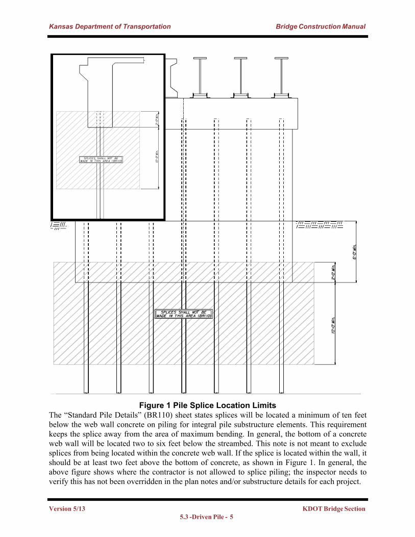
Figure 1 Pile Splice Location LimitsThe “Standard Pile Details” (BR110) sheet states splices will be located a minimum of ten feet below the web wall concrete on piling for integral pile substructure elements. This requirement keeps the splice away from the area of maximum bending. In general, the bottom of a concrete web wall will be located two to six feet below the streambed. This note is not meant to exclude splices from being located within the concrete web wall. If the splice is located within the wall, it should be at least two feet above the bottom of concrete, as shown in Figure 1. In general, the above figure shows where the contractor is not allowed to splice piling; the inspector needs to verify this has not been overridden in the plan notes and/or substructure details for each project.
Version 5/13 KDOT Bridge Section 5.3 -Driven Pile - 5
Kansas Department of Transportation Bridge Construction Manual
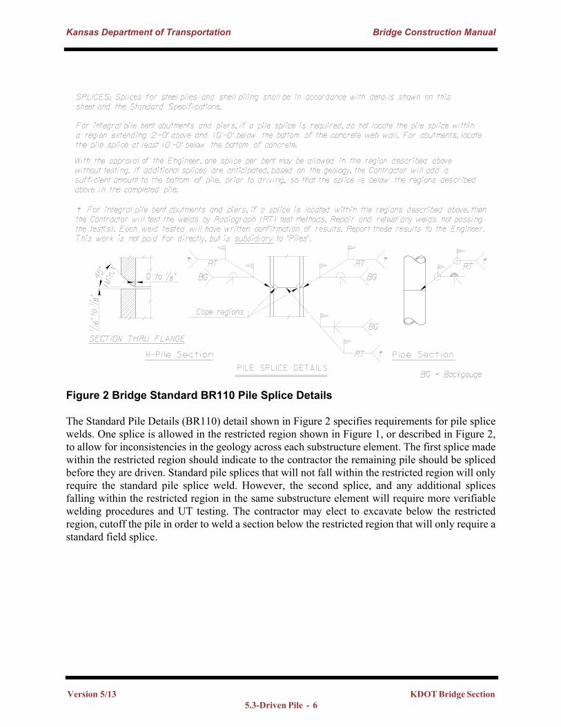
Figure 2 Bridge Standard BR110 Pile Splice Details
The Standard Pile Details (BR110) detail shown in Figure 2 specifies requirements for pile splice welds. One splice is allowed in the restricted region shown in Figure 1, or described in Figure 2, to allow for inconsistencies in the geology across each substructure element. The first splice made within the restricted region should indicate to the contractor the remaining pile should be spliced before they are driven. Standard pile splices that will not fall within the restricted region will only require the standard pile splice weld. However, the second splice, and any additional splices falling within the restricted region in the same substructure element will require more verifiable welding procedures and UT testing. The contractor may elect to excavate below the restricted region, cutoff the pile in order to weld a section below the restricted region that will only require a standard field splice.
Version 5/13 KDOT Bridge Section 5.3-Driven Pile - 6
Kansas Department of Transportation Bridge Construction Manual
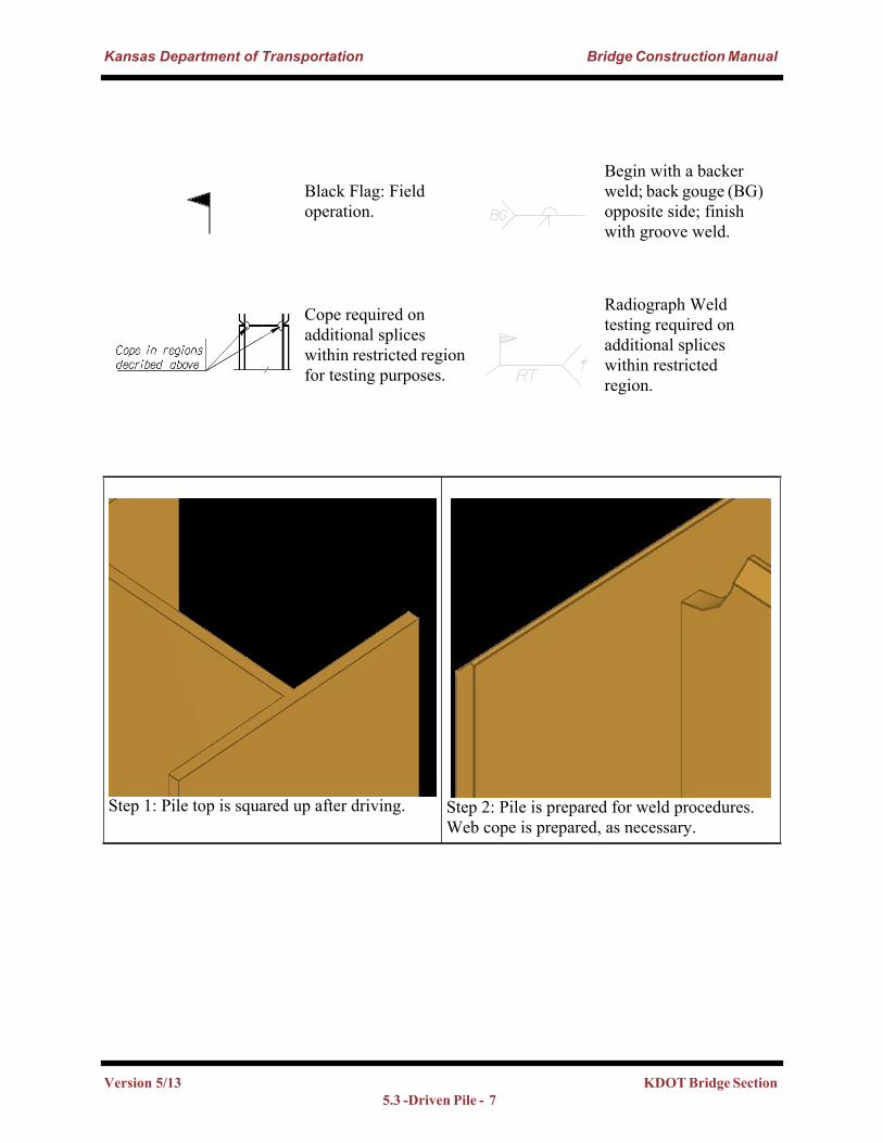
Black Flag: Field operation.
Begin with a backer weld; back gouge (BG) opposite side; finish with groove weld.
Cope required on additional splices within restricted region for testing purposes.
Radiograph Weld testing required on additional splices within restricted region.
Step 1: Pile top is squared up after driving. Step 2: Pile is prepared for weld procedures. Web cope is prepared, as necessary.
Version 5/13 KDOT Bridge Section 5.3 -Driven Pile - 7
Kansas Department of Transportation Bridge Construction Manual
5.3.3. Types of Piles
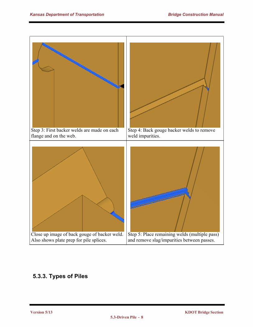
Step 3: First backer welds are made on each flange and on the web.
Step 4: Back gouge backer welds to remove weld impurities.
Close up image of back gouge of backer weld. Also shows plate prep for pile splices.
Step 5: Place remaining welds (multiple pass) and remove slag/impurities between passes.
Version 5/13 KDOT Bridge Section 5.3-Driven Pile - 8
Kansas Department of Transportation Bridge Construction Manual
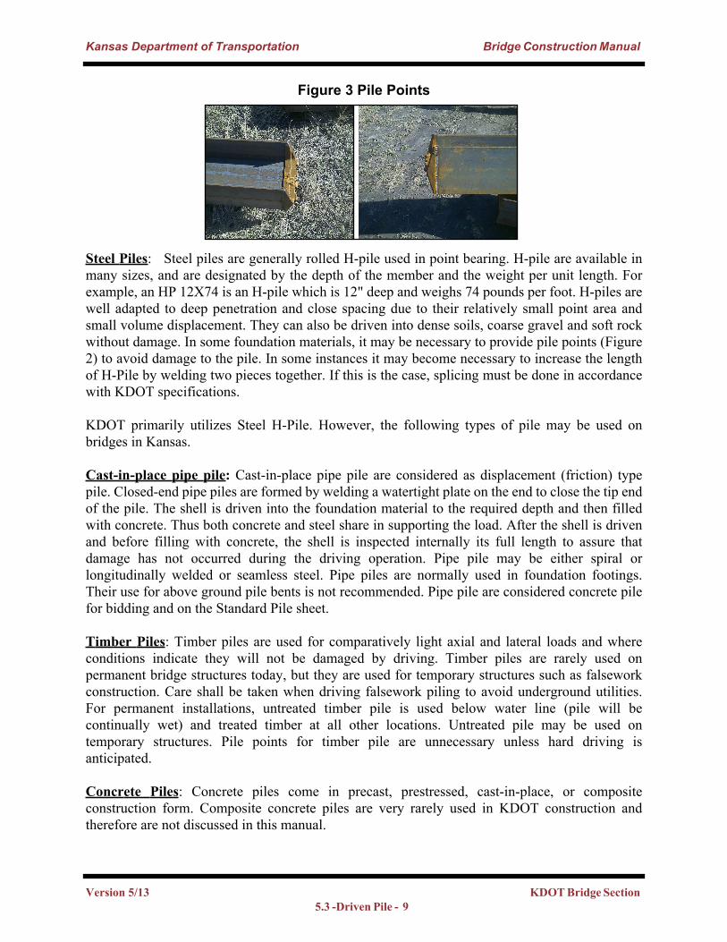
Figure 3 Pile Points
Steel Piles: Steel piles are generally rolled H-pile used in point bearing. H-pile are available in many sizes, and are designated by the depth of the member and the weight per unit length. For example, an HP 12X74 is an H-pile which is 12" deep and weighs 74 pounds per foot. H-piles are well adapted to deep penetration and close spacing due to their relatively small point area and small volume displacement. They can also be driven into dense soils, coarse gravel and soft rock without damage. In some foundation materials, it may be necessary to provide pile points (Figure 2) to avoid damage to the pile. In some instances it may become necessary to increase the length of H-Pile by welding two pieces together. If this is the case, splicing must be done in accordance with KDOT specifications.
KDOT primarily utilizes Steel H-Pile. However, the following types of pile may be used on bridges in Kansas.
Cast-in-place pipe pile: Cast-in-place pipe pile are considered as displacement (friction) type pile. Closed-end pipe piles are formed by welding a watertight plate on the end to close the tip end of the pile. The shell is driven into the foundation material to the required depth and then filled with concrete. Thus both concrete and steel share in supporting the load. After the shell is driven and before filling with concrete, the shell is inspected internally its full length to assure that damage has not occurred during the driving operation. Pipe pile may be either spiral or longitudinally welded or seamless steel. Pipe piles are normally used in foundation footings. Their use for above ground pile bents is not recommended. Pipe pile are considered concrete pile for bidding and on the Standard Pile sheet.
Timber Piles: Timber piles are used for comparatively light axial and lateral loads and where conditions indicate they will not be damaged by driving. Timber piles are rarely used on permanent bridge structures today, but they are used for temporary structures such as falsework construction. Care shall be taken when driving falsework piling to avoid underground utilities. For permanent installations, untreated timber pile is used below water line (pile will be continually wet) and treated timber at all other locations. Untreated pile may be used on temporary structures. Pile points for timber pile are unnecessary unless hard driving is anticipated.
Concrete Piles: Concrete piles come in precast, prestressed, cast-in-place, or composite construction form. Composite concrete piles are very rarely used in KDOT construction and therefore are not discussed in this manual.
Version 5/13 KDOT Bridge Section 5.3 -Driven Pile - 9
Kansas Department of Transportation Bridge Construction Manual
• Precast piles: Precast piles are cast at a production site and shipped to the project site. The Contractor should take special care when moving these piles as not to create tension cracks. The pickup points on these piles should be as shown on the shop drawings.
• Prestressed Piles: Prestressed piles are produced in the same manner as a prestressed concrete beam. The advantage of prestressed piles is their ability to handle large loads while maintaining a relatively small cross section. Also, a prestressed pile is less likely to develop tension cracks during handling.
• Cast-In-Place-Piles: Cast-in-place pressure grouted piles are constructed by drilling with a continuous-flight, hollow-shaft auger to the required depth. A non-shrinking mortar is then injected, under pressure, through the hollow shaft as the rotating auger is slowly withdrawn. A reinforcing steel cage is placed in the shaft immediately after the auger is withdrawn. When a shell or casing is used the contractor must make sure that the inside of the casing is free of soil and debris before placing the concrete. This system is used when hammer noise or vibration could be detrimental to adjacent footings or structures.
5.3.3.1 Basis of Acceptance (Materials)Material for H–Pile and Steel Shells for Cast-in-Place Concrete Piles are covered by a Type A certification. With approved certification, the field Engineer may accept the piling provided a visual inspection shows that it meets dimensional requirements and that it can be identified with the mill test report by means of heat lot numbers painted or stamped on each piece.
5.3.3.2 Pile Order LengthsThe length and type of pile required by plan is given in a box under the Summary of Quantities on the General Notes and Quantities Sheet. The location and plan length for each pile is given on the elevation view of the geology sheet. The Contractor will most likely provide slightly more pile than required by the plans. This additional length is to account for any pile which is damaged during driving.
KDOT’s geology section may require the ideal length of pile to be determined in the field by driving one or more test piles. This will occur when the founding material is fractured, less competent than anticipated or otherwise variable. The Field Engineer may require additional test piles to be driven if sufficient information is not provided from the plan quantity and location for test pile. Typically one test pile per bent is all that is needed. The Contractor will no longer be required to wait to order pile until after the required test pile(s) are driven. The primary use of the test pile is now to verify the subterranean geology (Log of Continuous Pile form), elevations and soil types, which has been provided by the Geology section.
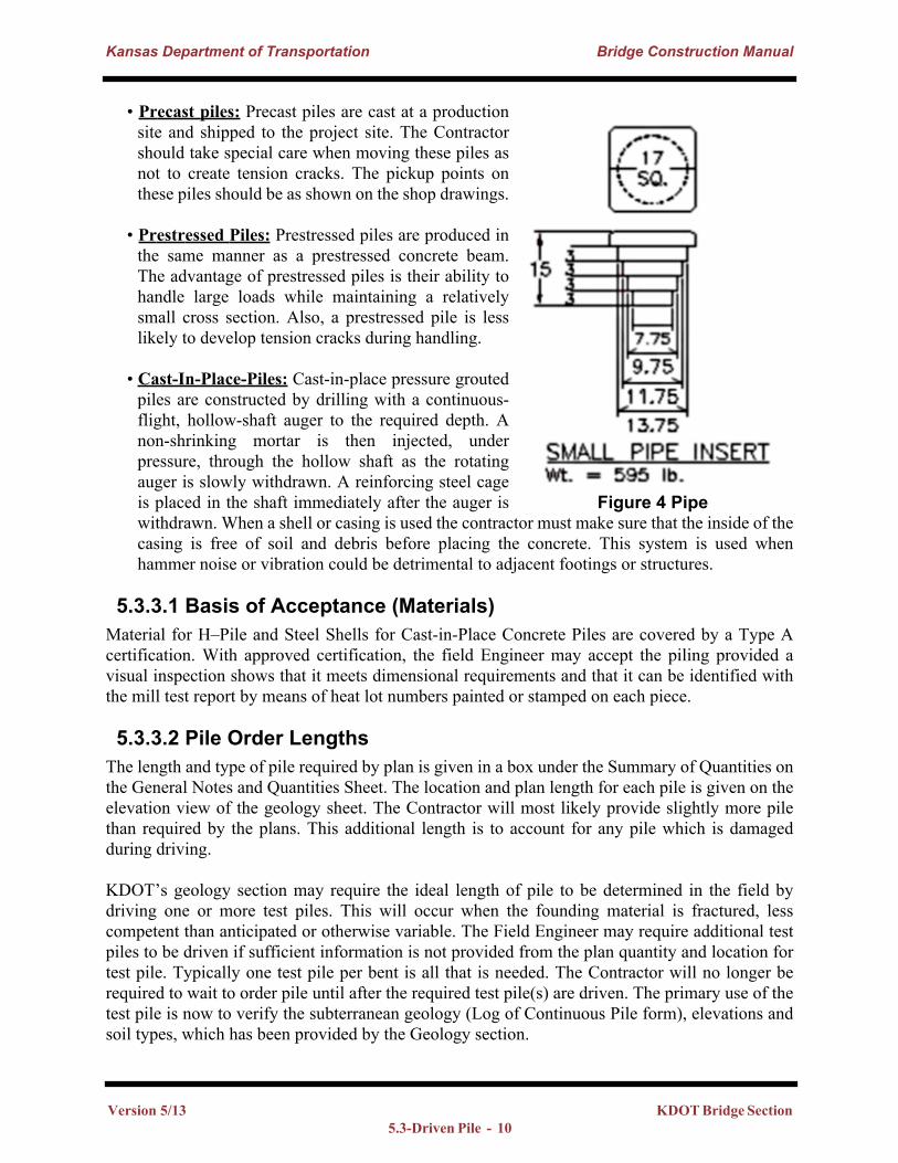
Figure 4 Pipe
Version 5/13 KDOT Bridge Section 5.3-Driven Pile - 10
Kansas Department of Transportation Bridge Construction Manual
5.3.4 Pile Driving EquipmentThis section is governed by Section 151.30 of the Standard Specifications Pile hammers are unique pieces of equipment. They serve two functions. One, they are tools used by the Contractor to drive pile; two, they are measuring instruments used by the Engineer to determine the bearing provided by the piles.
5.3.4.1 Pile Leads:Pile leads are required for use with all hammer types except the vibratory and sonic power hammers. The leads serve to contain the pile hammer and to direct its alignment, thus ensuring the pile receives a concentric impact with each blow. They also provide a means for bracing long, slender piles until they have been driven to sufficient penetration to develop their own support. It is essential the leads be well constructed to provide free movement of the hammer. For drop hammers, it is essential the leads be straight and true to prevent restrictions to free fall which would reduce the energy delivered.
There are several types of leads: underhung leads (pinned to the tip of the crane boom): extended 4-way leads (like the underhung lead, but extending vertically above the top of the boom); and swinging. Swinging leads are the most commonly found on Kansas bridge projects. There are usually two stabilization points which provide stability to the bottom of the leads. The leads are then held plumb or to the proper batter by a crane line. The leads are required to be long enough to accommodate, at a minimum, the pile length plus the length of the hammer. It is generally good practice to use a somewhat longer length as a contingency.
5.3.4.2 Pile Cap (Helmet): Driving different types and shapes of pile requires different types and shapes of pile caps. For standard H-pile or sheet pile, the specifications require grooves, or extended tabs, at the bottom of the cap to hold the pile in alignment with the axis of the hammer. The grooves or tabs for driving H-pile, or sheet pile, must be a minimum dimension of three inches. The cap required for driving pipe pile must have an insert into the top of the pipe a minimum of six inches. The depths are different because pipe pile are only manufactured using 36ksi steel, much weaker than the 50ksi H-pile, and the six inch requirement offers additional alignment accuracy while driving. If a pipe pile were misaligned and struck with the hammer causing damage at the top of the pipe, the Contractor would have a very difficult time squaring the top of the pipe in the field.
Pipe pile inserts typically have several stepped cylinders to allow one cap to be used to drive several sizes of pipe. The Pipe Pile detail in Figure 4, the insert would be acceptable to drive pipe pile varying in size from a 14” diameter down to a 10” diameter pipe. In accordance with the current specifications a minimum of 6" (2 stepped 3" cylinders) must be inside the pipe pile during driving operations. The weight of the helmet is not included in the weight of the striking part of the hammer (W). The helmet weight is included in the cap or anvil weight calculation (X) in the appropriate pile driving equation.
Version 5/13 KDOT Bridge Section 5.3 -Driven Pile - 11
Kansas Department of Transportation Bridge Construction Manual
5.3.4.3 Types of Hammers:
Drop hammer / Gravity hammer – This is the original pile driving hammer. It consists of a steel ram that is guided within a set of leads. The hammer is raised to a certain height and allowed to drop on top of the pile, thus producing the driving reaction. This type of hammer is most often used for driving falsework pile, but sometimes it is used for driving production pile, especially shorter piling. It has the disadvantage of slow operation and ram velocity. If a drop hammer is used for production pile, it is generally necessary to provide a steel cap and shock block over the pile during the driving.
For timber piles the hammer weight shall not be less than 2000 lbs, and preferably not less than 3500 lbs, and the drop will not exceed 12’. When the contractor wants to use a gravity hammer on steel and concrete piling, the hammer must weigh at least 3500 lbs and the drop still must not exceed 12’. In no case will the hammer weigh less than the pile plus the cap. In addition, the falling weight must move within a guide.
The energy provided by a drop hammer is simply calculated by multiplying the weight of the ram by its vertical drop.
Single acting power driven hammer – Hammers of this type are basically power gravity hammers. The difference between a gravity hammer and a single acting power hammer is that the ram (striking part) is encased in a steel frame work and is raised by steam or compressed air rather than by the crane load lines. The frequency of the blows is also considerably higher than a drop hammer. The ram mass is usually greater than a drop hammer and the vertical travel is usually less than that of a drop hammer. Any type of power hammer is usually more efficient than a drop hammer because there is less time between blows for the soil to set up around the pile. A typical hammer of this type utilizes a ram weight of 5000 lbs with a 3 ft drop. It is adequate for most pile less than 70 feet in length. The energy of this type of hammer is calculated exactly like the drop hammer.
Double Acting Power Driven Hammer – The ram is raised by steam or compressed air, as in the case of the single acting power hammer. When the ram approaches the top of its stroke a valve is opened into a chamber at the top of the cylinder allowing high pressure air or steam into the cylinder forcing the ram downward. Some double acting hammers utilize a light ram, operating at a high frequency, to develop the energy blows comparable to those developed by heavier, slower acting hammers. The advantage of the lighter ram hammer is that there is less time between blows for soil to re-settle against the pile, thus increasing the driving efficiency and decreasing the drive time. The energy is generally related to frequency and is obtained by referring to the manufacturer’s specifications. The manufacturer's rating is a maximum rating and is probably never obtained in the field. Therefore, KDOT specifications require a 20 percent reduction in rated energy for bearing computation.
Diesel Power Driven Hammers – Single acting diesel hammers are probably the most common type found on bridge projects in Kansas. They are simply a one cylinder diesel engine consisting of a steel cylinder containing a ram and an anvil. The ram is raised initially by an outside power source (crane) and dropped. As the ram drops, it activates a fuel pump, which injects fuel into a
Version 5/13 KDOT Bridge Section 5.3-Driven Pile - 12
Kansas Department of Transportation Bridge Construction Manual
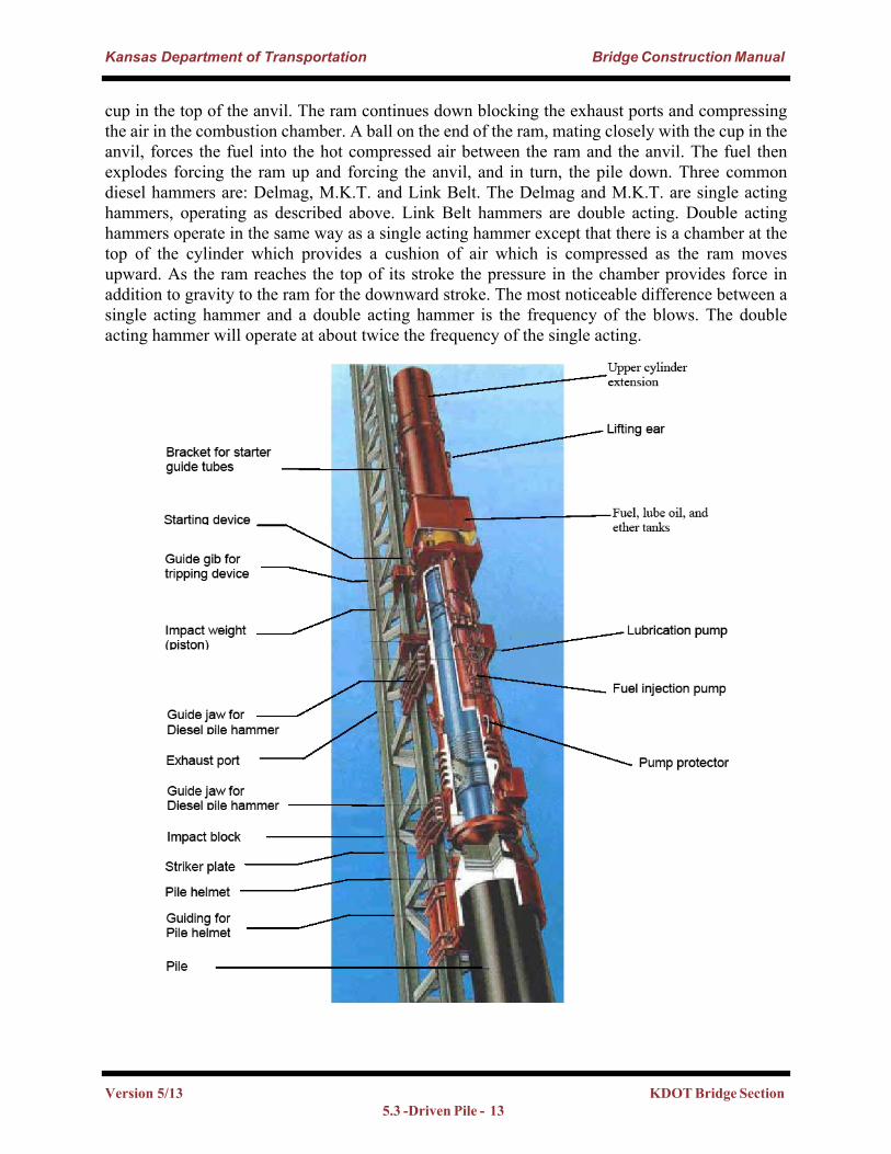
cup in the top of the anvil. The ram continues down blocking the exhaust ports and compressing the air in the combustion chamber. A ball on the end of the ram, mating closely with the cup in the anvil, forces the fuel into the hot compressed air between the ram and the anvil. The fuel then explodes forcing the ram up and forcing the anvil, and in turn, the pile down. Three common diesel hammers are: Delmag, M.K.T. and Link Belt. The Delmag and M.K.T. are single acting hammers, operating as described above. Link Belt hammers are double acting. Double acting hammers operate in the same way as a single acting hammer except that there is a chamber at the top of the cylinder which provides a cushion of air which is compressed as the ram moves upward. As the ram reaches the top of its stroke the pressure in the chamber provides force in addition to gravity to the ram for the downward stroke. The most noticeable difference between a single acting hammer and a double acting hammer is the frequency of the blows. The double acting hammer will operate at about twice the frequency of the single acting.
Version 5/13 KDOT Bridge Section 5.3 -Driven Pile - 13
Kansas Department of Transportation Bridge Construction Manual
Vibratory and Sonic Power Driven Hammers – These are the most recent developments in pile hammer technology. They are comparatively heavy, requiring handling equipment of greater capacity than required for conventional pile hammers. The Vibratory Hammer vibrates the pile at frequencies and amplitudes which tend to break the bond between the pile surface and the adjacent soils, thus delivering more of the developed energy to the tip of the pile. The Sonic Hammer operates at a higher frequency than the vibratory hammer, usually 80 to 150 cycles per second. At this frequency, the pile changes minutely in cross sectional dimension and length with each cycle, thus enlarging the cavity then elongating the pile. The matter of determining the pile bearing values for these hammers is a problem. Often the vibratory hammer is used to position the pile to plan tip elevation, then a diesel hammer is used to drive the pile to plan bearing.
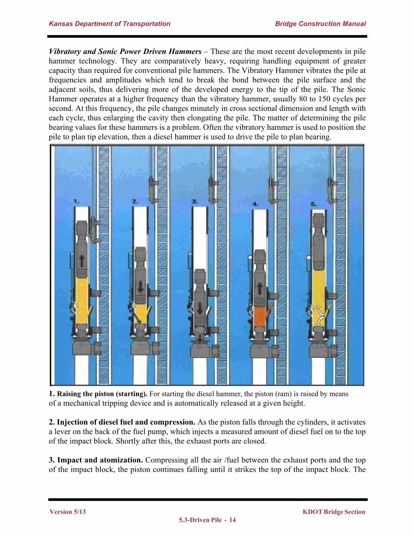
1. Raising the piston (starting). For starting the diesel hammer, the piston (ram) is raised by meansof a mechanical tripping device and is automatically released at a given height.
2. Injection of diesel fuel and compression. As the piston falls through the cylinders, it activates a lever on the back of the fuel pump, which injects a measured amount of diesel fuel on to the top of the impact block. Shortly after this, the exhaust ports are closed.
3. Impact and atomization. Compressing all the air /fuel between the exhaust ports and the top of the impact block, the piston continues falling until it strikes the top of the impact block. The
Version 5/13 KDOT Bridge Section 5.3-Driven Pile - 14
Kansas Department of Transportation Bridge Construction Manual
heat generated by the compression of air, in the presence of atomized fuel, causes the explosion of the fuel, throwing the piston upward and forcing the impact block downward against the pile.
4. Exhaust. While moving upwards, the piston will pass and open the exhaust ports. Exhaust gases will escape and the pressure in the cylinder will equalize.
5. Scavenging. The piston continues its upward momentum, which draws in fresh air for the nextcycle, cools the cylinders, and releases the pump lever. The pump lever returns to its startingposition, so that the pump will again be charged with fuel. Gravity stops the upward motion of thepiston and it starts falling through the cylinders once again.
5.3.4.4 Power for Hammers: Except for self-contained power source hammers, such as diesels, vibratory and sonic hammers, an outside power source is required for power-driven hammers. Years ago, steam was the primary outside power source, but currently air compressors are the most common source of power. Regardless of source, adequate power must be supplied if hammers are to function properly. Insufficient power will result in a hammer that operates at something less than specified stroke or frequency.
5.3.4.5 Diesel Hammer Terminology: Energy Range:The potential energy for single acting hammer is the product of ram weight and stroke; whereas, for double acting hammers, the force resulting from ''bounce chamber pressure” is added to the gravitational component. Some manufacturers may include the effects of the explosive force to the hammer potential energy.For inclined pile driving, only the vertical component of the stroke should be used in computing hammer potential energy.
Example: Energy is 75,230 ft-lbs, batter is 3:12.
Energy Vertical Component = 75,230 * = 70,073
Model:This is the model name designation given by the manufacturer to each hammer. Usually, it provides some description of the hammer (e.g., Delmag D30 hammer has a ram weight of 6600 lbs).
Manufacturer:The name of the manufacturing company.
Type:Single acting hammers are open ended at the top while double acting hammers are closed ended. Single acting hammers allow the ram to travel outside the cylinder which makes it visible for inspection of the stroke. Double acting hammers utilize a bounce chamber for increasing the hammer rate of operation. The ram is not visible in a double acting hammer.
Version 5/13 KDOT Bridge Section 5.3 -Driven Pile - 15
Kansas Department of Transportation Bridge Construction Manual
Blows per Minute:Number of strokes per minute. For single acting hammers, the rate can be empirically correlated to the stroke. The hammer rate depends on many factors including but not limited to, the hammer, the type and length of pile, as well as soil conditions. The height of the stroke of a single actingdiesel hammer can be computed from the following equation: H = 0.04 * t2. Where H is the height of the stroke in ft., and t is the length of time in seconds to record 10 strokes.
Weight of Striking Part:This is the weight of the part of the hammer that actually impacts the pile. This is commonly known as the “ram or piston”. Hammer rated energy and general effectiveness is a direct function of the weight of its striking part. In some cases, this weight is indicated as part of the hammer model designation.
Total Weight:This is the total weight of the hammer. This value is important in sizing the crane, transportation requirements and other aspects involving the hammer.
Hammer Length:This is the total length of the hammer in its normal operating configuration. This excludes any accessories which may be present between the hammer and the pile head.
Maximum Stroke:Maximum attainable stroke. Values obtained under favorable controlled conditions. Strokes under common field conditions vary depending on hammer mechanical condition, cushion and pile elastic effects, soil resistance and general hammer-cushion-pile-soil dynamic compatibility.
Jaw Dimensions:Dimensions of the hammer guides which interface with the leads. All diesel hammers have “female” type jaws and most have provisions for changeable guides.
Fuel Consumption:This is the amount of fuel (diesel) per hour that a hammer might consume. Actual amount is subject to operating variations. For proper hammer function, the appropriate type of fuel must be used.
Ram (Piston): This is the internal mass that moves up and down in the cylinder. The ram masses for different hammers are given in the appendix at the end of this chapter.
Helmets (driving caps or anvil blocks) for steel piling: These are provided for use with standard bases when driving sheet pile or H-pile. The upper ring is filled with a cushion material.
Cushion Material: Cushions soften the sharp blow of the hammer and distribute the load evenly.
Version 5/13 KDOT Bridge Section 5.3-Driven Pile - 16
Kansas Department of Transportation Bridge Construction Manual
Follower: Followers are placed between the top of the pile and the hammer when it is necessary to drive the head of pile below the reach of the hammer. Using followers introduces an additional uncertainty to the dynamic pile equations. Followers should not be used without permission from the District Engineer.
5.3.5 KDOT Specifications for Hammer Sizes:Section 151.30
(a) Hammers for Timber Piles.Gravity hammers for driving timber piles shall have a mass not less than 2,000 lbs and preferably not less than 3,500 lbs. The fall shall be so regulated as to avoid injury to the piles, and in no case shall exceed 12 feet. When a steam or diesel hammer is used the total energy developed by the hammer shall be not less than 6,000 foot-pounds per blow.
(b) Hammers for Steel Piles, Steel Sheet Piles, and Shells for Cast-in-Place Concrete Piles.Gravity hammers for driving steel piles, steel sheet piles and shell piles shall have a mass not less than 3,500 lbs. In no case shall the gravity hammer weigh less than the pile being driven plus the weight of the driving cap. All gravity hammers shall be equipped with hammer guides to ensure concentric impact on the drive head or pile cushion. The fall shall be so regulated as to avoid injury to the piles and in no case shall exceed 12 feet. Steam hammers or diesel hammers for driving steel piles, steel sheet piles, and shells for cast-in-place concrete piles shall be of such size that the rated gross energy of the hammer in foot-pounds shall be not less than 2½ times the weight of the pile in pounds. In no case shall the hammer develop less than 6,000 foot-pounds per blow.
Contractor certified weights may be used for the weight of gravity hammers.
(c) Hammers for Prestressed Concrete Piles.Unless otherwise provided, prestressed concrete piles shall be driven with a diesel, steam or air hammer which shall develop an energy per blow at each full stroke of the piston of not less than one foot-pound for each pound of weight driven. In no case shall the energy developed by the hammer be less than 6,000 foot-pounds per blow.
(d) Vibratory Hammers.Vibratory hammers may be used only when specifically allowed by the Contract documents or in writing by the Engineer. Vibratory hammers, if permitted, should preferably be used in combination with pile load testing and re-tapping with an impact hammer. In addition, one of every ten piles driven with a vibratory hammer shall be re-tapped with an impact hammer of suitable energy to verify that acceptable load capacity was achieved.
(e) Hammer Cushion.All impact pile driving equipment except gravity hammers shall be equipped with a suitable thickness of hammer cushion material to prevent damage to the hammer or pile and to insure uniform driving behavior. Hammer cushions shall be made of durable, manufactured material, which will retain uniform properties during driving. Except for use with a gravity hammer, all
Version 5/13 KDOT Bridge Section 5.3 -Driven Pile - 17
Kansas Department of Transportation Bridge Construction Manual
wood, wire rope, and asbestos hammer cushions are specifically disallowed and shall not be used. A striking plate shall be placed on the hammer cushion to insure uniform compression of the cushion material. The hammer cushion shall be inspected in the presence of the Engineer when beginning pile driving at each substructure element or after each 100 hours of pile driving, whichever is less. Whenever there is a reduction of hammer cushion thickness exceeding 25 percent of the original thickness, the hammer cushion shall be replaced by the Contractor before driving is permitted to continue.
The following are acceptable types of hammer cushion material. If the contractor proposes a material type that is not included in this list, contact the Bureau of Materials and Research.
Micarta (Conbest) – This is an electrical insulating material composed of fabric and phenol. It must be replaced when it begins to disintegrate or when it delaminates into various layers.
Nylon (Blue or other colors) – This material comes in 2" thick blocks. Occasional vertical cracking is not detrimental. However, after the cushion develops horizontal cracks, it should be replaced.
Hamortex – This material consists of metallized paper reels. It has good engineering properties but needs attention as it may compress or disintegrate.
Force 10, Forbon, and Fosterlon – These materials are provided by manufacturers of pile driving equipment.
Aluminum – Aluminum is often used to separate layers of softer cushioning material. The aluminum does no cushioning itself; however, it is thought to extract the heat from the cushion stack. Once the aluminum is deformed or broken, it should be replaced.
NOTE: Wood (plywood or hardwood) will probably remain the most common type of material used as a pile cushion for gravity hammers.
5.3.6 Pile Driving Mechanics:The length of stroke or fall of the hammer ram is a factor that influences the energy delivered by the hammer. As mentioned above, for a single-acting hammer,
Energy = (weight of ram) X (height of fall)
The weight of the ram is an important factor, since a heavy-ram impact hammer working on a short stroke is more effective in driving a pile than a light-ram long-stroke hammer. The weight of the ram, the length and speed of the stroke, and their relation to the weight of the pile is important to the proper driving of the pile. In theory, a pile can be of such a length that all the energy, which it receives from a hammer blow, is absorbed into its mass. Under these circumstances, a blow of the hammer will not advance the point of the pile. To appreciate this statement, it is necessary to understand what happens when the hammer hits the pile.
Version 5/13 KDOT Bridge Section 5.3-Driven Pile - 18
Kansas Department of Transportation Bridge Construction Manual
A hammer blow causes the pile to compress and rebound. This compression and rebound travels through the pile from the head down to the tip in the form of a wave, thus driving the pile into the ground. As the wave travels through the pile, energy is lost. In a short pile, this effect is negligible and can be disregarded. In a long pile, the energy losses due to the temporary compression of the pile can be considerable. Using an undersized hammer results in a driving resistance which is higher than the actual resistance, and thus a lower bearing capacity. For this reason, it is absolutely necessary that heavy-ram hammers be used in the driving of long piles.
The size of the ram should be gauged for the work that has to be done. A heavy-ram slow-acting hammer is more effective than a light-ram fast-acting hammer in driving a pile of a given weight, even though the two hammers may have the same rated energy per blow. The heavier-ram hammer will drive the pile deeper with each blow and will produce a more accurate bearing value than the equally rated lighter-ram hammer. As a general rule, pile driving should employ the heaviest-ram hammer that will not damage the pile. If the ram weight exceeds twice the pile weight, the pile material should be checked for resistance to impact.
5.3.6.1 Reviewing the Information on the Plans:Type of pile: Called out on the General Notes Sheet in a box under the Summary of Quantities (example: Use only HP10x42). This designation identifies the pile to be used as an H-Pile, with 10 indicating the long dimension of the web is 10 inches, and the pile has a weight of 42 pounds per linear foot.
Pile Length: Called out on the General Notes Sheet, Construction Layout and Geology Sheet (example: 9 @ 40’-0”). This notifies the inspector there should be 9 pile at least 40 feet long used in the substructure element. Pile Location: Geology Sheet Plan View
Pile Orientation: This locates the direction of the web (example: strong axis or weak axis)
Pile Batter: This is the slope of the pile as driven (example: 3/12 = 3” horizontal per 12” vertical.). Unless shown otherwise on the plans, pile shall be driven plumb.
Design Pile Load: This is the load the bridge designer and checker agreed upon based on all combination of live load, dead load, wind, water etc.
Allowable Pile Load: Found in the general notes, this is the minimum required driving resistance to be accepted by the Engineer. The maximum driving resistance allowed will also be shown within this note.
Depth of Pile: The General Notes Sheet will include a note directing the Contractor to drive the pile to penetrate or bear upon a specified formation. Or, the note will direct the contractor to drive to a specified depth and resistance. The Geology sheets will show the formations and their approximate elevationsThe tip elevation is not called out explicitly, but may be estimated from the top of pile elevation and the length of pile specified on the geology sheet.
Version 5/13 KDOT Bridge Section 5.3 -Driven Pile - 19
Kansas Department of Transportation Bridge Construction Manual
Pre-Drill: The bid item “Pre-Drilled Pile Holes” will appear in the Summary of Quantities and the depth of pre-drill will be in the general notes.
Cut-off elevation (top of pile): This elevation is shown on the Construction Layout in the profile view. This locates the top of the pile within the pile cap, abutment or pile bent. Usually, the embedment is between 2 feet to 3 feet in an abutment; one foot (1'-0”) in a footing.
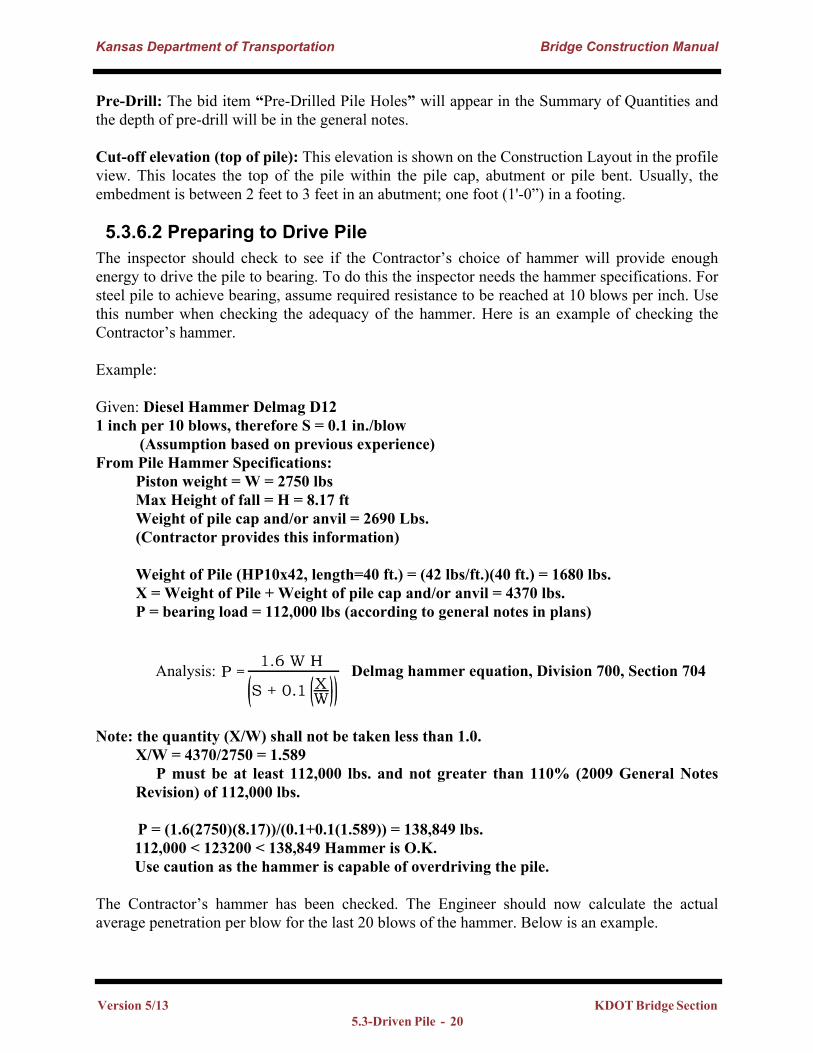
5.3.6.2 Preparing to Drive PileThe inspector should check to see if the Contractor’s choice of hammer will provide enough energy to drive the pile to bearing. To do this the inspector needs the hammer specifications. For steel pile to achieve bearing, assume required resistance to be reached at 10 blows per inch. Use this number when checking the adequacy of the hammer. Here is an example of checking the Contractor’s hammer.
Example:
Given: Diesel Hammer Delmag D121 inch per 10 blows, therefore S = 0.1 in./blow (Assumption based on previous experience)From Pile Hammer Specifications: Piston weight = W = 2750 lbs Max Height of fall = H = 8.17 ft Weight of pile cap and/or anvil = 2690 Lbs. (Contractor provides this information)
Weight of Pile (HP10x42, length=40 ft.) = (42 lbs/ft.)(40 ft.) = 1680 lbs. X = Weight of Pile + Weight of pile cap and/or anvil = 4370 lbs. P = bearing load = 112,000 lbs (according to general notes in plans)
Analysis: Delmag hammer equation, Division 700, Section 704
Note: the quantity (X/W) shall not be taken less than 1.0. X/W = 4370/2750 = 1.589 P must be at least 112,000 lbs. and not greater than 110% (2009 General Notes
Revision) of 112,000 lbs.
P = (1.6(2750)(8.17))/(0.1+0.1(1.589)) = 138,849 lbs.112,000 < 123200 < 138,849 Hammer is O.K. Use caution as the hammer is capable of overdriving the pile.
The Contractor’s hammer has been checked. The Engineer should now calculate the actual average penetration per blow for the last 20 blows of the hammer. Below is an example.
Version 5/13 KDOT Bridge Section 5.3-Driven Pile - 20
Kansas Department of Transportation Bridge Construction Manual
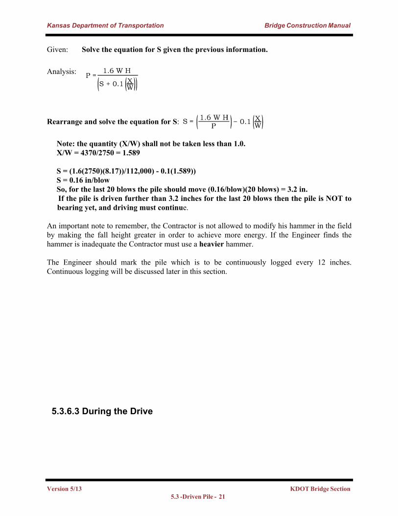
Given: Solve the equation for S given the previous information.
Analysis:
Rearrange and solve the equation for S:
Note: the quantity (X/W) shall not be taken less than 1.0. X/W = 4370/2750 = 1.589
S = (1.6(2750)(8.17))/112,000) - 0.1(1.589)) S = 0.16 in/blow So, for the last 20 blows the pile should move (0.16/blow)(20 blows) = 3.2 in. If the pile is driven further than 3.2 inches for the last 20 blows then the pile is NOT to
bearing yet, and driving must continue.
An important note to remember, the Contractor is not allowed to modify his hammer in the field by making the fall height greater in order to achieve more energy. If the Engineer finds the hammer is inadequate the Contractor must use a heavier hammer.
The Engineer should mark the pile which is to be continuously logged every 12 inches. Continuous logging will be discussed later in this section.
5.3.6.3 During the Drive
Version 5/13 KDOT Bridge Section 5.3 -Driven Pile - 21
Kansas Department of Transportation Bridge Construction Manual
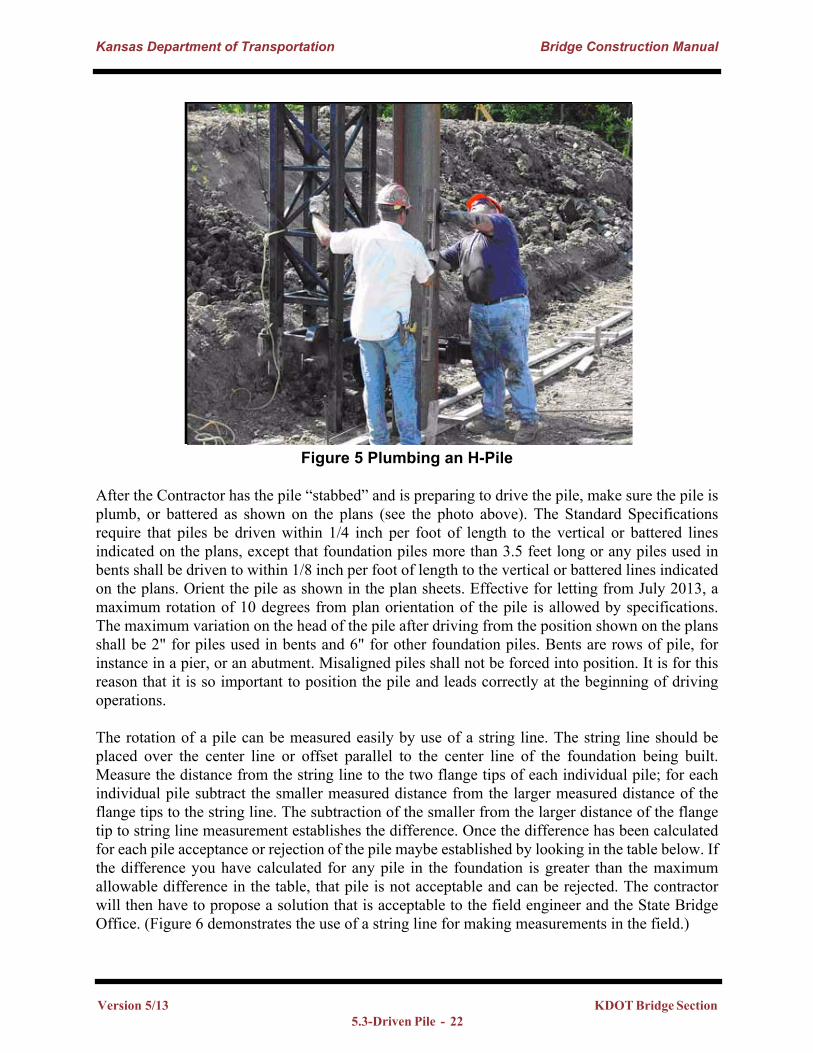
Figure 5 Plumbing an H-Pile
After the Contractor has the pile “stabbed” and is preparing to drive the pile, make sure the pile is plumb, or battered as shown on the plans (see the photo above). The Standard Specifications require that piles be driven within 1/4 inch per foot of length to the vertical or battered lines indicated on the plans, except that foundation piles more than 3.5 feet long or any piles used in bents shall be driven to within 1/8 inch per foot of length to the vertical or battered lines indicated on the plans. Orient the pile as shown in the plan sheets. Effective for letting from July 2013, a maximum rotation of 10 degrees from plan orientation of the pile is allowed by specifications. The maximum variation on the head of the pile after driving from the position shown on the plans shall be 2" for piles used in bents and 6" for other foundation piles. Bents are rows of pile, for instance in a pier, or an abutment. Misaligned piles shall not be forced into position. It is for this reason that it is so important to position the pile and leads correctly at the beginning of driving operations.
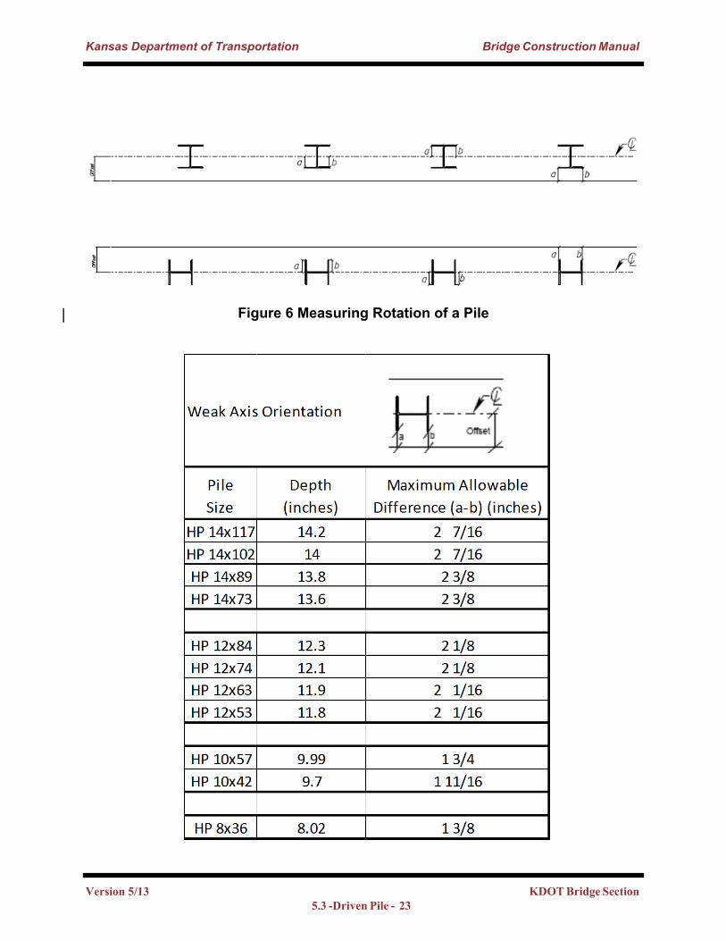
The rotation of a pile can be measured easily by use of a string line. The string line should be placed over the center line or offset parallel to the center line of the foundation being built. Measure the distance from the string line to the two flange tips of each individual pile; for each individual pile subtract the smaller measured distance from the larger measured distance of the flange tips to the string line. The subtraction of the smaller from the larger distance of the flange tip to string line measurement establishes the difference. Once the difference has been calculated for each pile acceptance or rejection of the pile maybe established by looking in the table below. If the difference you have calculated for any pile in the foundation is greater than the maximum allowable difference in the table, that pile is not acceptable and can be rejected. The contractor will then have to propose a solution that is acceptable to the field engineer and the State Bridge Office. (Figure 6 demonstrates the use of a string line for making measurements in the field.)
Version 5/13 KDOT Bridge Section 5.3-Driven Pile - 22
Kansas Department of Transportation Bridge Construction Manual
Figure 6 Measuring Rotation of a Pile
Version 5/13 KDOT Bridge Section 5.3 -Driven Pile - 23
Kansas Department of Transportation Bridge Construction Manual
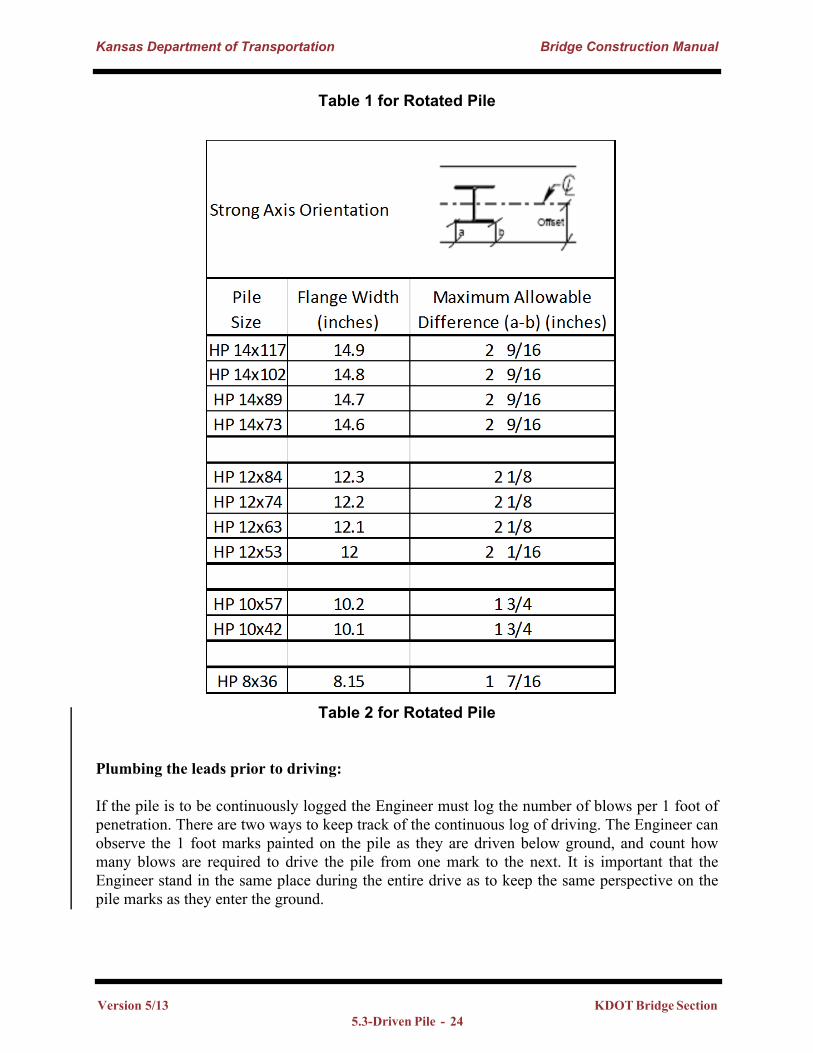
Table 1 for Rotated Pile
Table 2 for Rotated Pile
Plumbing the leads prior to driving:
If the pile is to be continuously logged the Engineer must log the number of blows per 1 foot of penetration. There are two ways to keep track of the continuous log of driving. The Engineer can observe the 1 foot marks painted on the pile as they are driven below ground, and count how many blows are required to drive the pile from one mark to the next. It is important that the Engineer stand in the same place during the entire drive as to keep the same perspective on the pile marks as they enter the ground.
Version 5/13 KDOT Bridge Section 5.3-Driven Pile - 24
Kansas Department of Transportation Bridge Construction Manual
The second way of keeping track of continuous log of driving is to use a theodolite. The Engineer should set the cross-hairs of the instrument close to the ground level. The Engineer observes through the instrument as driving proceeds and counts the number of blows between the marks on the pile as described above. As the pile nears the plan formation or plan length, the Engineer must monitor the items required to calculate bearing; namely, the average penetration “S” for the last 20 blows (5 for gravity hammers), the length of stroke for single acting hammers and bounce chamber pressure for double acting hammers.
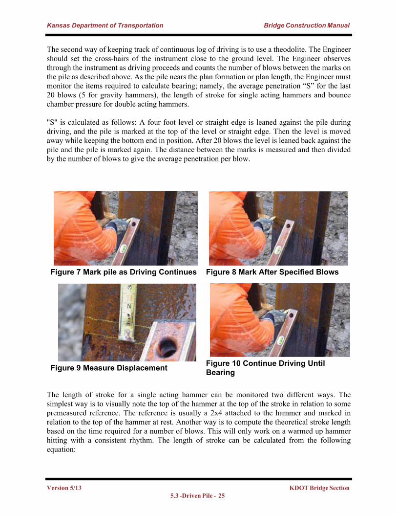
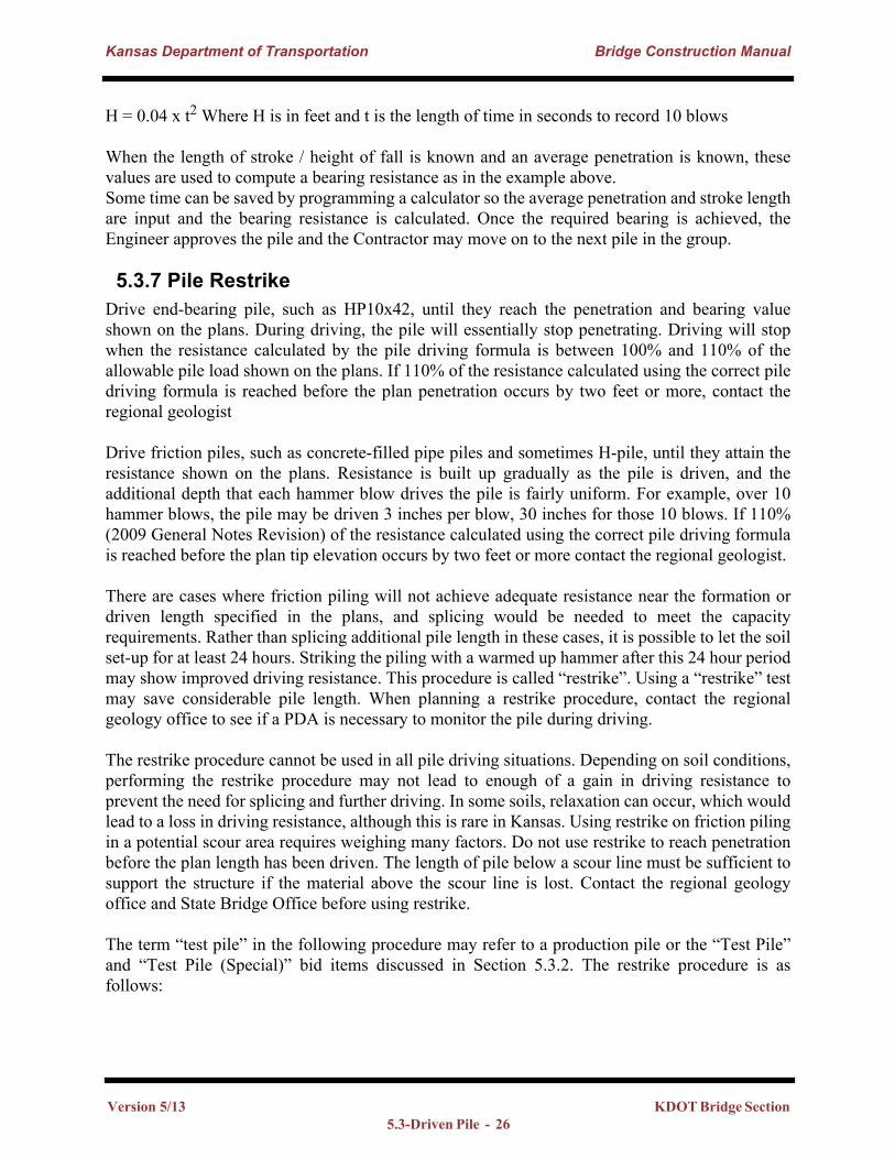
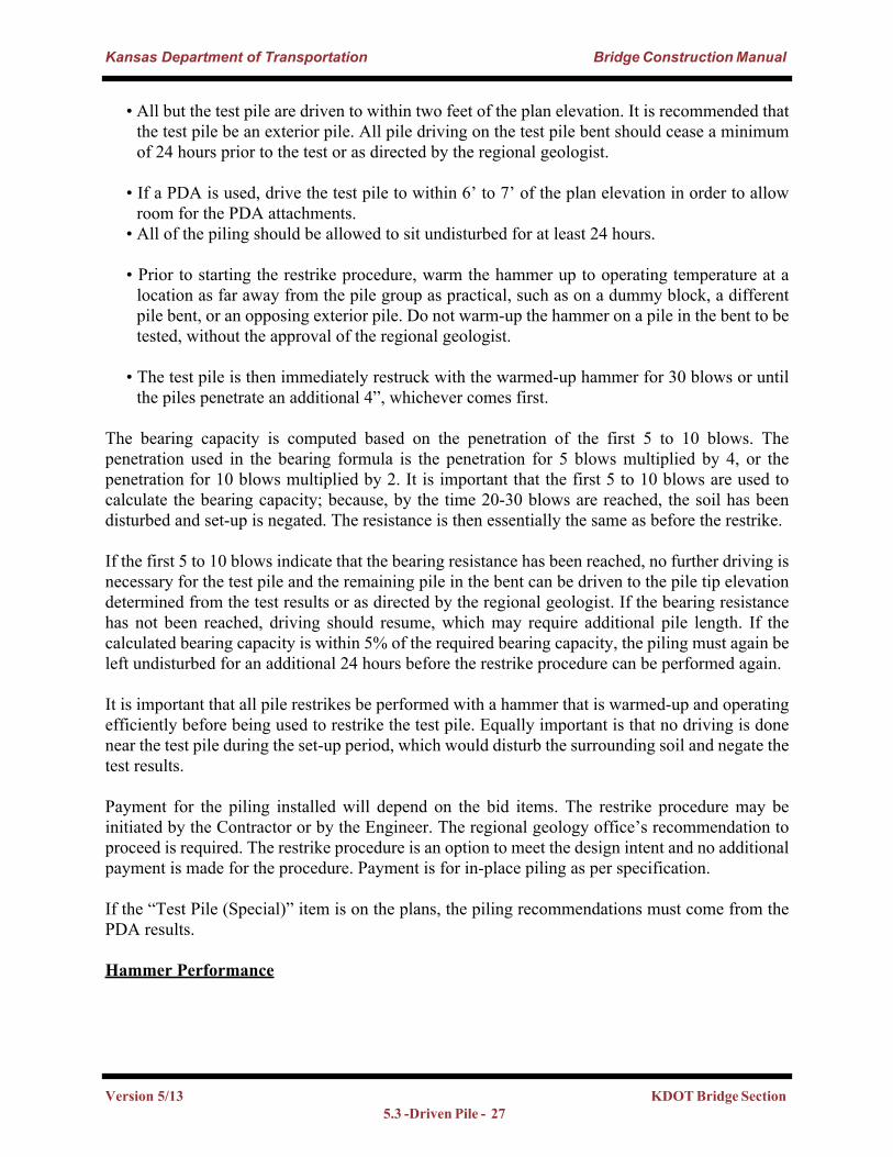
"S" is calculated as follows: A four foot level or straight edge is leaned against the pile during driving, and the pile is marked at the top of the level or straight edge. Then the level is moved away while keeping the bottom end in position. After 20 blows the level is leaned back against the pile and the pile is marked again. The distance between the marks is measured and then divided by the number of blows to give the average penetration per blow.
The length of stroke for a single acting hammer can be monitored two different ways. The simplest way is to visually note the top of the hammer at the top of the stroke in relation to some premeasured reference. The reference is usually a 2x4 attached to the hammer and marked in relation to the top of the hammer at rest. Another way is to compute the theoretical stroke length based on the time required for a number of blows. This will only work on a warmed up hammer hitting with a consistent rhythm. The length of stroke can be calculated from the following equation:
Figure 7 Mark pile as Driving Continues Figure 8 Mark After Specified Blows
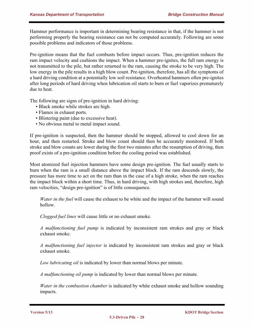
Figure 9 Measure Displacement Figure 10 Continue Driving Until Bearing
Version 5/13 KDOT Bridge Section 5.3 -Driven Pile - 25
Kansas Department of Transportation Bridge Construction Manual
H = 0.04 x t2 Where H is in feet and t is the length of time in seconds to record 10 blows
When the length of stroke / height of fall is known and an average penetration is known, these values are used to compute a bearing resistance as in the example above.Some time can be saved by programming a calculator so the average penetration and stroke length are input and the bearing resistance is calculated. Once the required bearing is achieved, the Engineer approves the pile and the Contractor may move on to the next pile in the group.
5.3.7 Pile Restrike Drive end-bearing pile, such as HP10x42, until they reach the penetration and bearing value shown on the plans. During driving, the pile will essentially stop penetrating. Driving will stop when the resistance calculated by the pile driving formula is between 100% and 110% of the allowable pile load shown on the plans. If 110% of the resistance calculated using the correct pile driving formula is reached before the plan penetration occurs by two feet or more, contact the regional geologist
Drive friction piles, such as concrete-filled pipe piles and sometimes H-pile, until they attain the resistance shown on the plans. Resistance is built up gradually as the pile is driven, and the additional depth that each hammer blow drives the pile is fairly uniform. For example, over 10 hammer blows, the pile may be driven 3 inches per blow, 30 inches for those 10 blows. If 110% (2009 General Notes Revision) of the resistance calculated using the correct pile driving formula is reached before the plan tip elevation occurs by two feet or more contact the regional geologist.
There are cases where friction piling will not achieve adequate resistance near the formation or driven length specified in the plans, and splicing would be needed to meet the capacity requirements. Rather than splicing additional pile length in these cases, it is possible to let the soil set-up for at least 24 hours. Striking the piling with a warmed up hammer after this 24 hour period may show improved driving resistance. This procedure is called “restrike”. Using a “restrike” test may save considerable pile length. When planning a restrike procedure, contact the regional geology office to see if a PDA is necessary to monitor the pile during driving.
The restrike procedure cannot be used in all pile driving situations. Depending on soil conditions, performing the restrike procedure may not lead to enough of a gain in driving resistance to prevent the need for splicing and further driving. In some soils, relaxation can occur, which would lead to a loss in driving resistance, although this is rare in Kansas. Using restrike on friction piling in a potential scour area requires weighing many factors. Do not use restrike to reach penetration before the plan length has been driven. The length of pile below a scour line must be sufficient to support the structure if the material above the scour line is lost. Contact the regional geology office and State Bridge Office before using restrike.
The term “test pile” in the following procedure may refer to a production pile or the “Test Pile” and “Test Pile (Special)” bid items discussed in Section 5.3.2. The restrike procedure is as follows:
Version 5/13 KDOT Bridge Section 5.3-Driven Pile - 26
Kansas Department of Transportation Bridge Construction Manual
• All but the test pile are driven to within two feet of the plan elevation. It is recommended that the test pile be an exterior pile. All pile driving on the test pile bent should cease a minimum of 24 hours prior to the test or as directed by the regional geologist.
• If a PDA is used, drive the test pile to within 6’ to 7’ of the plan elevation in order to allow room for the PDA attachments.
• All of the piling should be allowed to sit undisturbed for at least 24 hours.
• Prior to starting the restrike procedure, warm the hammer up to operating temperature at a location as far away from the pile group as practical, such as on a dummy block, a different pile bent, or an opposing exterior pile. Do not warm-up the hammer on a pile in the bent to be tested, without the approval of the regional geologist.
• The test pile is then immediately restruck with the warmed-up hammer for 30 blows or until the piles penetrate an additional 4”, whichever comes first.
The bearing capacity is computed based on the penetration of the first 5 to 10 blows. The penetration used in the bearing formula is the penetration for 5 blows multiplied by 4, or the penetration for 10 blows multiplied by 2. It is important that the first 5 to 10 blows are used to calculate the bearing capacity; because, by the time 20-30 blows are reached, the soil has been disturbed and set-up is negated. The resistance is then essentially the same as before the restrike.
If the first 5 to 10 blows indicate that the bearing resistance has been reached, no further driving is necessary for the test pile and the remaining pile in the bent can be driven to the pile tip elevation determined from the test results or as directed by the regional geologist. If the bearing resistance has not been reached, driving should resume, which may require additional pile length. If the calculated bearing capacity is within 5% of the required bearing capacity, the piling must again be left undisturbed for an additional 24 hours before the restrike procedure can be performed again.
It is important that all pile restrikes be performed with a hammer that is warmed-up and operating efficiently before being used to restrike the test pile. Equally important is that no driving is done near the test pile during the set-up period, which would disturb the surrounding soil and negate the test results.
Payment for the piling installed will depend on the bid items. The restrike procedure may be initiated by the Contractor or by the Engineer. The regional geology office’s recommendation to proceed is required. The restrike procedure is an option to meet the design intent and no additional payment is made for the procedure. Payment is for in-place piling as per specification.
If the “Test Pile (Special)” item is on the plans, the piling recommendations must come from the PDA results.
Hammer Performance
Version 5/13 KDOT Bridge Section 5.3 -Driven Pile - 27
Kansas Department of Transportation Bridge Construction Manual
Hammer performance is important in determining bearing resistance in that, if the hammer is not performing properly the bearing resistance can not be computed accurately. Following are some possible problems and indicators of those problems.
Pre-ignition means that the fuel combusts before impact occurs. Thus, pre-ignition reduces the ram impact velocity and cushions the impact. When a hammer pre-ignites, the full ram energy is not transmitted to the pile, but rather returned to the ram, causing the stroke to be very high. The low energy in the pile results in a high blow count. Pre-ignition, therefore, has all the symptoms of a hard driving condition at a potentially low soil resistance. Overheated hammers often pre-ignites after long periods of hard driving when lubrication oil starts to burn or fuel vaporizes prematurely due to heat.
The following are signs of pre-ignition in hard driving:• Black smoke while strokes are high.• Flames in exhaust ports.• Blistering paint (due to excessive heat).• No obvious metal to metal impact sound.
If pre-ignition is suspected, then the hammer should be stopped, allowed to cool down for an hour, and then restarted. Stroke and blow count should then be accurately monitored. If both stroke and blow counts are lower during the first two minutes after the resumption of driving, then proof exists of a pre-ignition condition before the cooling period was established.
Most atomized fuel injection hammers have some design pre-ignition. The fuel usually starts to burn when the ram is a small distance above the impact block. If the ram descends slowly, the pressure has more time to act on the ram than in the case of a high stroke, when the ram reaches the impact block within a short time. Thus, in hard driving, with high strokes and, therefore, high ram velocities, “design pre-ignition” is of little consequence.
Water in the fuel will cause the exhaust to be white and the impact of the hammer will sound hollow.
Clogged fuel lines will cause little or no exhaust smoke.
A malfunctioning fuel pump is indicated by inconsistent ram strokes and gray or black exhaust smoke.
A malfunctioning fuel injector is indicated by inconsistent ram strokes and gray or black exhaust smoke.
Low lubricating oil is indicated by lower than normal blows per minute.
A malfunctioning oil pump is indicated by lower than normal blows per minute.
Water in the combustion chamber is indicated by white exhaust smoke and hollow sounding impacts.
Version 5/13 KDOT Bridge Section 5.3-Driven Pile - 28
Kansas Department of Transportation Bridge Construction Manual
Worn piston rings are indicated by short strokes. When the pile is near the required resistance the hammer stroke should be near the maximum published height.
Overheating is indicated as above in the pre-ignition section.
5.3.8 Log of Pile DrivingLog of Continuous Pile Driving:
A Continuous Pile Driving Record should be recorded for a representative pile on each abutment and pier footing on a structure. The record should be inclusive from the beginning of the drive to the final bearing of the pile. For structures under 755 feet in length, the above information will be required on two footings only. One of the piles should be in an abutment footing and the other in a pier footing near the opposite end of the structure. If the structure has no piling in the pier footings, then the record should be made for a pile in each abutment footing.
For structures over 755 feet in length, the continuous record stipulated above will be required on three footings, one on an abutment and two on pier footings. If the piers have no piling then the information will be recorded on one pile from each abutment.
The log of Continuous Pile Driving records are the same as records obtained for structures that have the bid item of test piles, and will, therefore, not need to be recorded in cases where structures include the bid item of test piles.
The State bridge Office plots the pile driving log on the Geology Sheet of the as-built plans for historical purposes.
FORM 217 – LOG OF PILE DRIVINGThe form shown below can be found in the KDOT forms warehouse: (English Version): http://www.ksdot.org/burdesign/bridge/constructionmanual/217us.xls
1.FORM POLICY: Complete and submit this report as soon as all piling is driven in an abutment or pier. Also, complete and submit this report for all test piling immediately after driving each test pile.
2.PREPARING REPORT:
A.General Information:
1. “Type of Hammer” – Enter the brand and model of the hammer used.2. “Hammer Weight” – Enter the weight of the striking part of the hammer (i.e. piston or
ram) as denoted on the specification plate on the hammer or in Figure IV-1 of the Construction Manual (4.03.08).
Version 5/13 KDOT Bridge Section 5.3 -Driven Pile - 29
Kansas Department of Transportation Bridge Construction Manual
3. “Cap and/or Anvil Weight” - Enter the weight of any cap and/or anvil to be used while driving pile.
4. “Energy Rating (ft-lbs)” - Enter the energy rating as denoted on the specifications plate on the hammer, or in Figure IV-1 of the Construction Manual (4.03.08). Also, note the 80% factor in the Standard Specifications (704.04(e)).
5. “County” and “Project” – Enter the name of the county. Enter the project number, if available.
6. “Br. No. and/or Sta.” - Enter the bridge number of the structure for which the piling was driven. Also, enter the station for the structure, not the station for the pier or abutment where the pile was driven. For city or county structures that don’t have a bridge number, the station of the structure is sufficient.
7. “Type of Pile” – Enter the entire bid item name for the type of piling used. Examples: PILE (STEEL) (HP10X42), TEST PILE (STEEL) (HP12X57), PILE (PRESTRESSED CONCRETE) (12 in.) or TEST PILE (SPECIAL) (HP10X42).
8. “Plan Note Overdrive %” – A drop down menu will allow the user to select 110 or 150 to determine the maximum resistance allowed based upon the “Piling” note within the General Notes for the project.
9. “Min. Resistance Required” - Enter minimum required bearing as specified under the “Piling” note on the plans. This is not to be confused with the bearings listed under the Design Data.
10. “Max. Resistance Allowed” - The maximum bearing is now calculated based upon the value listed under the “Piling” note on the plans. This value is now based upon This is not to be confused with the bearings listed under the Design Data.
After filling out the General Information sheet, select the tab associated with the hammer to be used to drive the pile. “Gravity (Steel),” “Air-Steam (Single),” “Air-Steam (Double),” “Delmag & McKierman – Terry,” “Link-Belt” tabs are the hammer types available. Many comments are available all across the new form, and can be read by placing the cursor over the cell with the red triangle in the upper right corner of the cell.
1. “Abutment” or “Pier” - Enter the number, taken directly from the design plans, for the abutment or pier where the pile will be driven.
2. “Number, Individual Length, and Total Length of Pile” – Enter the total number of pile in the substructure unit (abutment beam, pier footing, pier bent, etc.), then enter an “@” symbol, the total length of one pile, and the sum of all pile in the unit. (8 @ 45 = 360 ft.)
3. “Plan Cutoff Elev. (ft.)” – Enter the Top of Pile elevation given on the plans for the substructure unit.
4. “Wt. per foot piling (lbs/ft)” – This data can be found in different locations for different types of pile.
a.For H-pile, physical properties are in the name. Such as with HP12X53, the 12 represents the long dimension of the web in inches, and the 53 represents the weight per linear foot.
b.For steel shell pile, the weight per meter can be found on mill test/lading ticket from the supplier. If that information is not available, some physical properties for steel shell pile are shown in Table 1 at the back of this document.
Version 5/13 KDOT Bridge Section 5.3-Driven Pile - 30
Kansas Department of Transportation Bridge Construction Manual
c.For pre-stressed concrete pile, if the weight per foot is not given on the test report, the inspector can use a density of 150lbs/ft3 to calculate a theoretical weight per foot:
i.12 inches square – 150 lbs/ft3
ii.14 inches square – 204 lbs/ft3
iii.16 inches octagonal – 220 lbs/ft35. “Type of Cushion Mat’l” – Plywood, oak, whatever material will be used to protect the top
of the pile.6. “Footing Sketch” – Draw a sketch of the footing with piles numbered to represent the
numbers listed in the “Pile No.” column of this form. The north arrow must be shown.
B. Driving Information: Measure and report piling length to the nearest one-hundredth of a foot (i.e. 0.01 ft.). Report all elevations to the nearest one-hundredth of a foot (i.e. 0.01 ft.).
1. “Pile No.” – Represents the as labeled in the footing sketch.
1. “Varied Plan Cutoff Elev.” is used if the substructure element is super-elevated and each pile has a distinct pile cutoff elevation. Enter the elevation listed on the plans for each pile so the “Pile Tip Elev.” field calculates correctly.
2. “Actual Length in Leads” – This is the length of pile the Contractor opts to use. This length is used to calculate the weight of the pile for use in the bearing formula, and the length can change as driving operations progress:
·When driving operations first start, the “Actual Length Placed in Leads” is equal to length of pile placed in the leads. If bearing is not achieved and a splice is required, the new value for “Actual Length Placed in Leads” is equal to the original length placed in the leads, plus the length of pile spliced on to it.
·If bearing is achieved prior to splicing the pile and the splice is made solely to achieve plan cutoff elevation, the “Length Placed in Leads” will increase by the amount spliced onto the pile to achieve plan cutoff elevation, and “Ordered and Accepted” will equal the “Length Placed in Leads.” In no case should the “Actual Length in Leads” be less than the “Length Left in Footing” cell.
3. “Ordered and Accepted” – Typically this is the length of pile the Engineer instructs the Contractor to use (i.e. the length of pile indicated on the plans). However, situations do arise where the “Ordered and Accepted” length will differ from the plans:
·If the length indicated on the plans is too short and additional length is needed to achieve bearing and “Plan Cutoff Elevation”, the Engineer instructs the Contractor how much additional length is to be spliced onto the pile. In which case, the “Ordered and Accepted” length is now equal to the original length on the plans, plus the additional length that the Engineer authorized being spliced.
·If the Contractor opts to use a longer pile than the Engineer authorized and the additional length, in part or in whole, is needed to achieve bearing and “Plan Cutoff Elevation”, the “Ordered and Accepted” length is equal to the length of pile
Version 5/13 KDOT Bridge Section 5.3 -Driven Pile - 31
Kansas Department of Transportation Bridge Construction Manual
left in place. Thus, the “Ordered and Accepted” length and “Length Left in Foundation” are equal.
·If the contract has test piling, the Engineer will determine the “Ordered and Accepted” length from the test pile data.
4. “Spliced after Drive” is used when the contractor drives a length of pile, then splices a section to the top, but does not drive the additional length. The accurate bearing is calculated on the length placed in leads, so do not change this number. If the length spliced onto the pile brings the total to more than the Ordered and Accepted length, the Ordered and Accepted length will be changed accordingly. Cutoff should not be an issue in this situation. The contractor will likely splice on the exact length needed to bring the pile up to cutoff elevation.
5. “Actual Cutoff” – The actual length of pile cutoff after achieving bearing and “Plan Cutoff Elevation.”
·The “Actual Cutoff” is not necessarily equal to “Pay Cutoff.”i.If the Contractor elects to use a longer pile than was specified by the
Engineer (“Ordered and Accepted”), the length in excess of the length specified by the Engineer is considered “Non Pay Cutoff.” (Example: The pile are supposed to be 20 foot sticks, but the Contractor uses a 40 foot stick on the first pile. Actual Cutoff is measured at 23 feet. This would equal 3 feet of “Pay Cutoff” and 20 feet of “Non Pay Cutoff” if this was the only pile to be driven.)
ii.The “Actual Cutoff” from one pile may be spliced in part, or in whole, to other pile. In which case, it will become part of the “Ordered and Accepted Length” on the pile receiving the splice. This depends on the length of pile the Engineer directs the Contractor to use. (Example: From above, the Contractor turns around and uses the 23 foot cutoff pile for the next pile. It is driven to bearing and Actual Cutoff is 8 feet, so Pay Cutoff for this pile is 5 feet, and the Non Pay Cutoff is equal to 3 feet. In total, for both pile, the Pay Cutoff sum is 8 feet and the Non Pay Cutoff sum is only equal to 3 feet, since all of the Non Pay Cutoff from the first pile has been used for the second pile. This prevents the State from paying for Cutoff for lengths of pile eventually used in the structure.)
5. “Length Left in Footing” is the PAY LENGTH, and is the length of pile left after Actual Cutoff is removed.
·If no splice is made, or a splice is made to extend the pile to achieve bearing, the “Length Left in Foundation” equals the “Actual Length Placed in Leads”, minus the “Actual Cutoff.”
·If a splice is made solely to achieve “Plan Cutoff Elevation” (i.e. bearing is achieved prior to splice), the “Length Left in Foundation” equals the “Ordered and Accepted” length equals the “Actual Length in Leads.”
Version 5/13 KDOT Bridge Section 5.3-Driven Pile - 32
Kansas Department of Transportation Bridge Construction Manual
6. “Pay Splices” – Enter the number of Pay Splices occurring for the individual pile. This does not include splices made for the Contractor’s convenience.
7. Length Left in Footing” is the PAY LENGTH, and is the length of pile left after Actual Cutoff is removed.
8. “Pile Tip Elev.” typically is the “Plan Cutoff Elev.” minus the “Length Left in Footing.” However, if the pile is battered, the batter needs to be taken into account to determine the tip elevation.
9. “Stroke (Drop of Hammer)” is observed by the inspector, and recorded in the appropriate column.
10. “Average Penetration” is equal to the penetration in inches for 20 blows divided by 20 blows.
11. “Computed Bearing Power” – Computed by the inspector immediately upon reaching a predetermined point to establish the actual bearing relationship with plan bearing. Even though laptops are routinely used in the field, an inspector should thoroughly understand the bearing formula and how to manually calculate the bearing, before a laptop is used.
12. “Range” – This will indicate where the driving process is for the entered data by displaying “Low,” “OK,” or “High” based on the Min and Max bearing numbers.
13. “Totals” – Automatic totals for each column for “Actual Length Placed in Leads”, “Ordered and Accepted Length”, “Actual Measured Cutoff” and “Length Left in Foundation.”
14. “Accepted Length” – Equals the total from the “Ordered and Accepted” column.
15. “Non Pay Cutoff” – Represents the length of pile in excess of the length specified by the Engineer, and was cutoff. It equals the “Actual Cutoff” column minus “Pay Cutoff” minus the “Non Pay Cutoff used for Splice (Reg)” cell.
16. “Non Pay Cutoff used for Splice” - Is the length of pile that was originally considered as part of the “Non Pay Cutoff”, but was spliced to another pile to achieve “Plan Cutoff Elevation” and/or bearing. A column exists for Reg, for production pile, and Test, for Non Pay Cutoff from a Test Pile. It is important for the inspector to keep track of the amount of Non Pay, or Pay Cutoff used in the structure. KDOT does not want to pay 75% of the contract price for Pay Cutoff, only to have the same pile spliced on and used in the structure to be paid at full contract price.
17. “Pay Cutoff used for Splice” – Is the length of pile that was originally considered as part of the “Pay Cutoff” from one pile, but was spliced to another pile to achieve “Plan Cutoff
Version 5/13 KDOT Bridge Section 5.3 -Driven Pile - 33
Kansas Department of Transportation Bridge Construction Manual
Elev.” and/or bearing. Since the cutoff was previously considered “Pay Cutoff”, deduct it from the “Pay Cutoff” total, so it is not paid for as “Pay Length” and “Pay Cutoff.” Show the deduction on the report for the footing where the cutoff came from. If this report has already been submitted, submit an amended report showing the deduction. (Example: A 6 foot stick of Pay Cutoff pile from Abutment 1 is spliced onto a pile in Pier 2. Go back to the report for Abutment 1 and enter 6 into the “Pay Cutoff used for Splice” cell so the pile does not get paid for as Pay Cutoff on the Abutment 1 report, but all, of a portion of it will get paid for as Pay Length and/or Pay Cutoff on the Pier 2 report.)
18. “Total Cutoff used for Splice” – Equals the “Non Pay Cutoff used for Splice” plus “Pay Cutoff used for Splice.”
19. “No. of Pay Splices” – Equals the total number of splices, ordered by the Engineer, to extend the pile beyond the original “Ordered and Accepted Length”. Splices made for the Contractor’s convenience are not considered pay splices.
20. “Pay Length” – Equals the total from the “Length Left in Footing” column.
21. “Pay Cutoff” – Equals the “Accepted Length” minus the total from the “Length Left in Foundation” column, minus “Pay Cutoff Used for Splice.”
22. “Remarks” – Provide a recap of all splicing information, and unique information about the pile driving operations:
a.Indicate if a splice was a pay or non-pay splice (i.e. instructed by the Engineer or the contractor’s option.)
b.Which pile a splice pile came from.c.Which pile a splice pile was spliced to.d.The length of each splice pile.e.Indicate if a splice was made after bearing was achieved.
22. “LOG OF CONTINUOUS PILE DRIVING AND/OR TEST PILE” – Record a continuous pile driving record for a representative pile on each abutment and pier footing on a structure. The record should be inclusive from the beginning of the drive to the final bearing of the pile. Refer to the example below.
a.“Total Pile Length”- Report the length of pile to be driven into the ground. Once the pile has developed enough resistance to require at least 1 blow per foot, begin recording in 1.0 foot increments. In the first “To” cell, if the pile drops 6.75 feet with the first three blows, enter 6.75 in the “To” cell, and enter “3” in the “Number of Blows” cell. If the pile drops 1.5 feet in the next two blows, enter “8.25” in the next “To” cell, and “2” in the next “Number of Blows” cell. At the point the pile
Version 5/13 KDOT Bridge Section 5.3-Driven Pile - 34
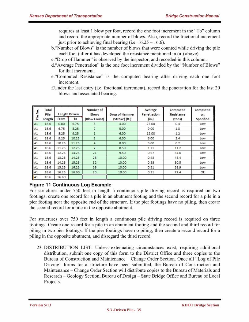
Kansas Department of Transportation Bridge Construction Manual
requires at least 1 blow per foot, record the one foot increment in the “To” column and record the appropriate number of blows. Also, record the fractional increment just prior to achieving final bearing (i.e. 16.25 – 16.6).
b.“Number of Blows” is the number of blows that were counted while driving the pile each foot (after it has developed the resistance mentioned in (a.) above).
c.“Drop of Hammer” is observed by the inspector, and recorded in this column.d.“Average Penetration” is the one foot increment divided by the “Number of Blows”
for that increment.e.“Computed Resistance” is the computed bearing after driving each one foot
increment.f.Under the last entry (i.e. fractional increment), record the penetration for the last 20
blows and associated bearing.
Figure 11 Continuous Log ExampleFor structures under 750 feet in length a continuous pile driving record is required on two footings; create one record for a pile in an abutment footing and the second record for a pile in a pier footing near the opposite end of the structure. If the pier footings have no piling, then create the second record for a pile in the opposite abutment.
For structures over 750 feet in length a continuous pile driving record is required on three footings. Create one record for a pile in an abutment footing and the second and third record for piling in two pier footings. If the pier footings have no piling, then create a second record for a piling in the opposite abutment, and disregard the third record.
23. DISTRIBUTION LIST: Unless extenuating circumstances exist, requiring additional distribution, submit one copy of this form to the District Office and three copies to the Bureau of Construction and Maintenance – Change Order Section. Once all “Log of Pile Driving” forms for a structure have been submitted, the Bureau of Construction and Maintenance – Change Order Section will distribute copies to the Bureau of Materials and Research – Geology Section, Bureau of Design – State Bridge Office and Bureau of Local Projects.
Version 5/13 KDOT Bridge Section 5.3 -Driven Pile - 35
Kansas Department of Transportation Bridge Construction Manual
24. SIGNATURES: Always include the names of the individuals that inspected the pile driving operations, checked the computations and submitted the form.
25. The following is a completed example of “Remarks” in a “Log of Pile Driving.” Note the “Plan Length” for each pile is 16.7 ft.
·Pile #1 - Driven to bearing with 0.2 ft. (non-pay cutoff) trimmed off to reach “Plan Cutoff Elevation.”
·Pile #2 – Driven to bearing with 1.90 ft trimmed off to reach “Plan Cutoff Elevation” - 1.7 ft (pay cutoff) and 0.2 ft (non-pay cutoff).
·Pile #3 – After driving 16.9 ft of piling bearing wasn’t achieved. To provide a fresh head 0.2 ft (non-pay cutoff) was trimmed off and 1.9 ft from #2 was spliced (pay splice) on (1.7 ft of pay cutoff, 0.2 ft of non-pay). The pile was then driven to bearing and 0.7 ft (pay cutoff) and 0.2 ft (non-pay) was cutoff.
·Pile #4 – Bearing was achieved after driving the 16.9 ft pile, but it was below cut off elevation. Thus, 0.2 ft (non-pay cutoff) was trimmed off to provide a fresh head, and 0.5 ft was spliced (pay splice) on to reach plan cutoff elevation.
·Pile #5 – The Contractor used a longer pile than was specified by the Engineer. Thus, the pile was driven to bearing with 0.5 ft (non-pay cutoff) and 0.20 ft (pay cutoff) cutoff.
·Pile #6 - Contractor elected to splice (non-pay splice) together two pieces of cutoff from Pier 1. After the pile was driven to bearing the resultant cutoff was 0.75 ft (non-pay cutoff) and 0.3 ft (pay cutoff). Appropriate amounts of Cutoff used for Splice have been deducted from Pier 1 sheet.
5.3.8.1 As-Built GeologyOccasionally the as-built pile lengths, and even pile locations, may vary from those shown on the plans. It is important for any deviation in foundation elements from the plans to be recorded on the as-built geology sheet and submitted to the District Engineer. The District Engineer will in turn submit these sheets the Bridge Office. Someone from the Bridge office will then incorporate those changes into the original geology sheet. This is done so that there is a permanent record for use in the future. An example of an as-built geology sheet is shown below.
Version 5/13 KDOT Bridge Section 5.3-Driven Pile - 36
Kansas Department of Transportation Bridge Construction Manual
Version 5/13 KDOT Bridge Section 5.3 -Driven Pile - 37
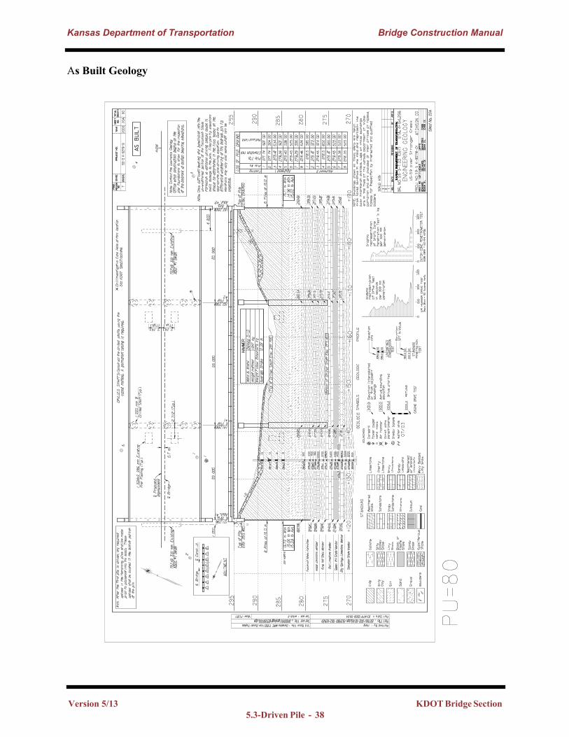
Kansas Department of Transportation Bridge Construction Manual
As Built Geology
Version 5/13 KDOT Bridge Section 5.3-Driven Pile - 38
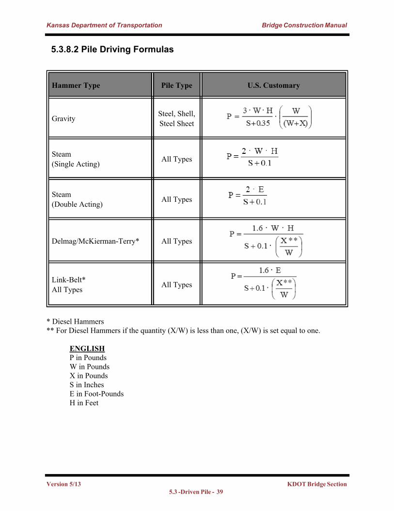
Kansas Department of Transportation Bridge Construction Manual
5.3.8.2 Pile Driving Formulas
* Diesel Hammers** For Diesel Hammers if the quantity (X/W) is less than one, (X/W) is set equal to one.
ENGLISHP in Pounds W in PoundsX in PoundsS in InchesE in Foot-Pounds H in Feet
Hammer Type Pile Type U.S. Customary
Gravity Steel, Shell, Steel Sheet
Steam (Single Acting) All Types
Steam (Double Acting) All Types
Delmag/McKierman-Terry* All Types
Link-Belt* All Types All Types
Version 5/13 KDOT Bridge Section 5.3 -Driven Pile - 39
Kansas Department of Transportation Bridge Construction Manual
5.3.8.3 Field Pile Driving GuideMany methods can be used to calculate resistance in the field. The inspector can program a calculator to compute resistance at the appropriate number of strokes, but this can be difficult because the height of the stroke and the penetration are both changing as the pile advances. The PDA calculates resistance as the pile is driven, but it is not currently specified on all projects. The field may request the PDA through the regional geology office. The State Bridge Office created the “Field Pile Driving Guide” to help the inspector calculate resistance as stroke and penetration change. This form will be available on the Forms Warehouse, or through contacting the Bridge Construction Manual Engineer.
First, the inspector needs to have all the appropriate information from the Contractor. If Form 217AA has been filled out, all of this information can be found there. Next, fill out the project information on the “General Information” sheet 217B. The plans will show the designer’s specified load for each substructure pile and the pile type, which will give the inspector the pile weight in units of pounds per foot. Additional sheets included in the form are related to the hammer that the contractor will use for the project. The inspector will go to the correct hammer sheet and enter data into the light green shaded cells. Enter the Length of Pile near to the length that will be left in the ground. This will provide the inspector with the calculations near the end of the drive as the pile reaches the specified load stated in the “Piling” note on the “General Notes” sheet of the plans. The Hammer, Cap, and Anvil weights will come from the contractor. It is important to make sure that the contractor’s hammer data is within the limits set in Sections 157 and 704 in the Standard Specification. The minimum and maximum penetration, “S”, will depend on the energy of the hammer and the piling that is being driven. Values of 1/8” and 1/4” per blow are appropriate for most cases; however, a blue “band” of acceptable values is the goal of Form 217B in order to give the inspector an achievable range in the field. The minimum and maximum hammer fall, “H”, will depend on the energy of the hammer and the piling that is being driven. For gravity hammers, the maximum fall may go up to 15’.
After the data is entered, the spreadsheet highlights the band of acceptable bearing values, and provides a graph based on Drop of Hammer vs. Penetration in 20 blows. The top line on the graph is the Minimum Bearing line; for a given hammer drop, the penetration in 20 blows must be less than the value given at this line. The bottom line on the graph is the Maximum Bearing line; for a given hammer drop, the penetration in 20 blows must be more than the value given by this line. For a small hammer drop, with a large penetration in 20 blows (above and left of the two lines), the pile has not achieved minimum bearing. For a large hammer drop, with a small penetration in 20 blows (below and right of the two lines), the pile has gone beyond the maximum bearing. The highlighted portion of “Computed Resistance” and the “Acceptable Range” in the graph can be adjusted by changing the range of hammer fall and the range of average penetration. While the contractor drives the piling, the inspector regularly checks the value of resistance for the observed fall of the hammer and pile penetration. Instructions are included on the “General Information” sheet within the form, and the Bridge Construction Manual Engineer should be contacted for further guidance.
Version 5/13 KDOT Bridge Section 5.3-Driven Pile - 40
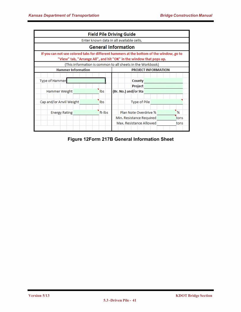
Kansas Department of Transportation Bridge Construction Manual
Figure 12Form 217B General Information Sheet
Version 5/13 KDOT Bridge Section 5.3 -Driven Pile - 41
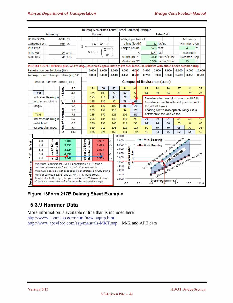
Kansas Department of Transportation Bridge Construction Manual
Figure 13Form 217B Delmag Sheet Example
5.3.9 Hammer DataMore information is available online than is included here: http://www.conmaco.com/html/new_equip.htmlhttp://www.apevibro.com/asp/manuals-MKT.asp M-K and APE data
Version 5/13 KDOT Bridge Section 5.3-Driven Pile - 42