Embed Size (px)
Citation preview
DRIVEN CONCRETE PILE FOUNDATION MONITORING WITH EMBEDDED DATA
COLLECTOR SYSTEM
Presented By: Paul SteinmanBased On An Evaluation By:
Rodrigo Herrera, Larry Jones, Peter Lai
FTBA/FDOT Construction Conference February 23, 2010
Embedded Data Collector
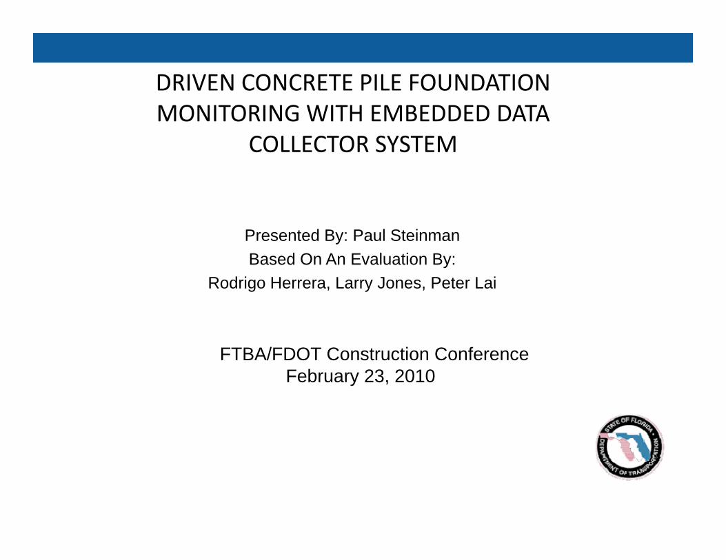
• Alternate method of pile driving monitoring was investigatedmonitoring was investigated through FDOT sponsored research
• University of Florida’s Final reporty p
• Theory
• First generation hardware and software
• Construction Project BB349
• The UF/FDOT technology was• The UF/FDOT technology was licensed for further development
Introduction
•Majority of Florida bridges are supported on deep foundationsfoundations.
•Most common deep foundation:pPrecast Prestressed Concrete piles.
•All test piles and some production piles are monitored with systems involving strain gauges and accelerometers attached at the top of the pileand accelerometers attached at the top of the pile.
Current FDOT Practice
• Test Pile Programg
Analysis using data obtained from top of the pile during drivingpile during driving.
• Based on the above information, Production Pile Lengths are estimated and Pile Driving CriteriaLengths are estimated and Pile Driving Criteria are established.
ll f d l• Installation of Production Piles.
What is Embedded Data Collector
• Two instrumentation levels embedded at top and bottom of the pilebottom of the pile.
• Wireless data transfer
B ddi t i t t ti t th il ti i• By adding extra instrumentation at the pile tip in addition to the one at pile head more data could be available that is not otherwise obtainableavailable that is not otherwise obtainable.
• Estimates soil damping for every blow during driving
• Real time estimates of static resistances i e side tip• Real‐time estimates of static resistances, i.e., side, tip and total.
• Antenna connects to laptop PCAntenna connects to laptop PC
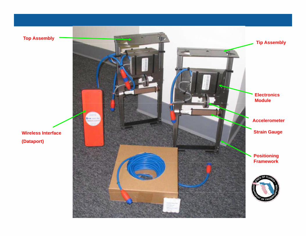
Tip AssemblyTop Assembly
Tip Assembly
Electronics Module
Wireless Interface
Accelerometer
Strain GaugeWireless Interface
(Dataport)
Strain Gauge
Positioning FrameworkFramework
Accelerometer
PositioningStrain Gauge Positioning Framework
Strain Gauge
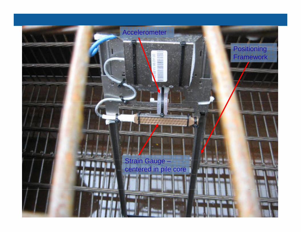
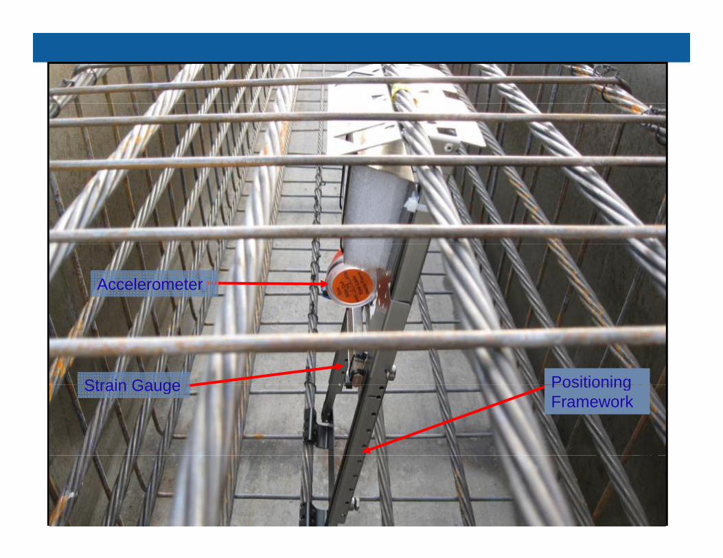
Accelerometer
Positioning Framework
Strain GaugeStrain Gauge –centered in pile core
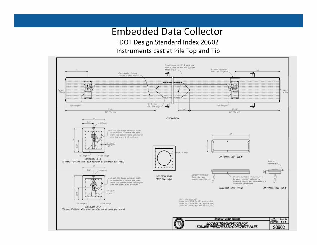
Embedded Data CollectorFDOT Design Standard Index 20602gInstruments cast at Pile Top and Tip
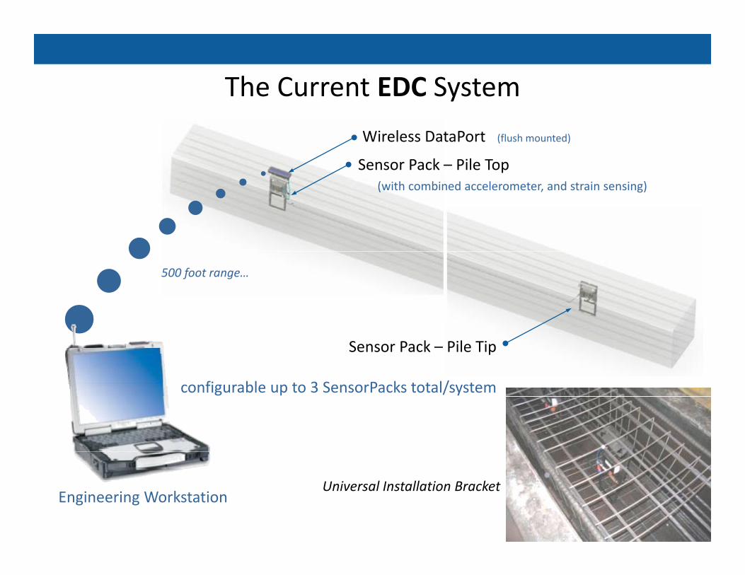
The Current EDC System
Wireless DataPort (flush mounted)
Sensor Pack – Pile Top(with combined accelerometer, and strain sensing)
500 foot range…
Sensor Pack – Pile Tip
configurable up to 3 SensorPacks total/system
Engineering WorkstationUniversal Installation Bracket
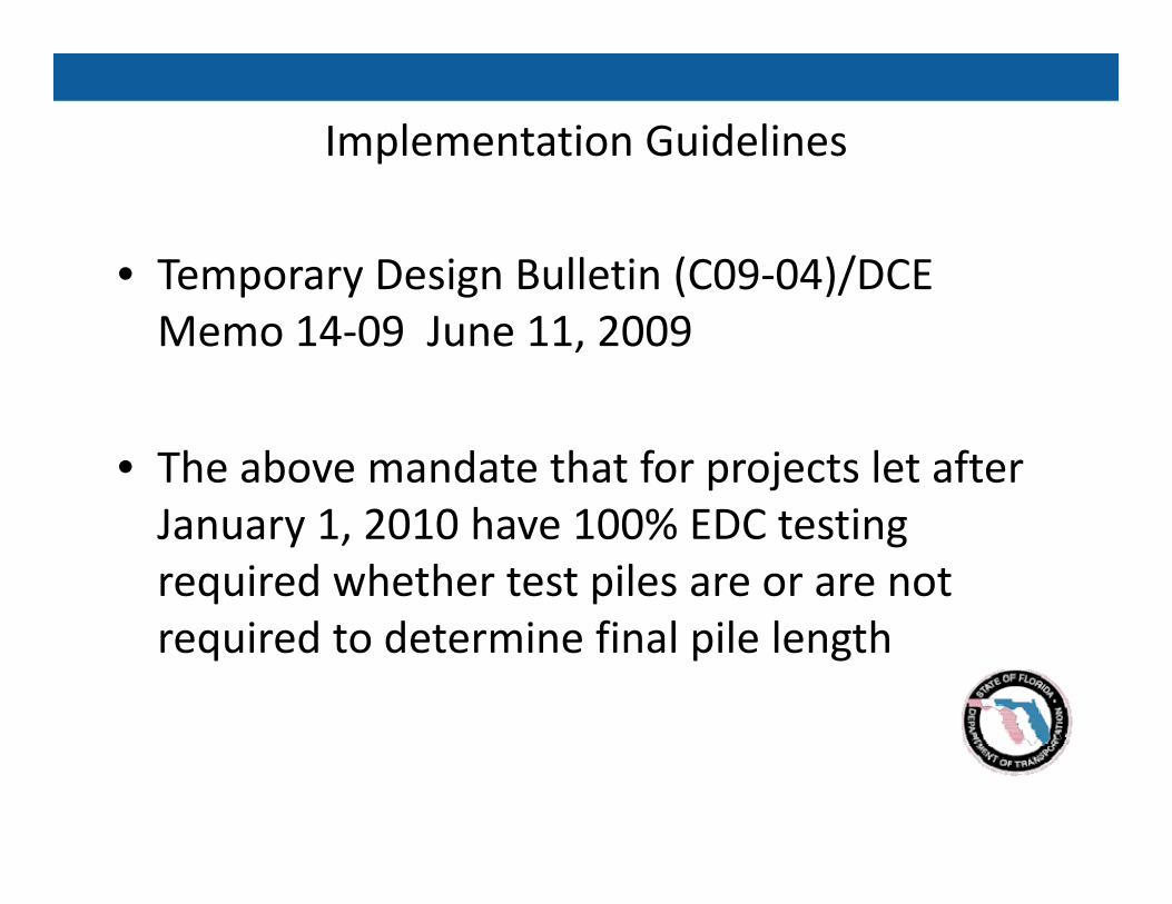
Implementation Guidelines
• Temporary Design Bulletin (C09‐04)/DCETemporary Design Bulletin (C09 04)/DCE Memo 14‐09 June 11, 2009
• The above mandate that for projects let after J 1 2010 h 100% EDC iJanuary 1, 2010 have 100% EDC testing required whether test piles are or are not
i d d i fi l il l hrequired to determine final pile length
455 Special Provisions
EDC implementation:
• SP 4550510A: All Bridge Projects with square prestressed concrete pile foundation, with test piles
• SP 4550510B: All Bridge Projects with squareSP 4550510B: All Bridge Projects with square prestressed concrete pile foundation, without test pilestest piles
455 Special ProvisionsEDC implementation: SP 4550510A:EDC implementation: SP 4550510A:
455‐5.11.1: Notify the Engineer two work days prior to placement of piles within the template and at least one work day prior to driving piles. Do not drive piles without the presence of the Engineer.
• The Engineer will determine pile capacity of the Test Piles based• The Engineer will determine pile capacity of the Test Piles based on the results of Dynamic Load Tests using externally mounted instruments. Allow the Engineer one work day after driving the d i l d d il l h d d d i hdynamic load tested pile to analyze the data and determine the damping value for the EDC equipment.
• After determining the appropriate damping value, the EngineerAfter determining the appropriate damping value, the Engineer will determine the capacity of the production piles for each pier or bent based on EDC equipment…
EDC implementation: SP 4550510A: (contd)• If the EDC does not perform to the satisfaction of the Engineer
due to actions of the Contractor, engage a Specialty Engineer to perform Dynamic Load Testing of the pile installation at no p y g padditional cost to the Department. Set Dynamic Load Test equipment to the damping value provided by the Engineer prior to driving the production pileto driving the production pile.
• If the Engineer requires an additional Dynamic Load test for comparison purposes on piles with a properly functioning EDC, the Contractor will be paid an additional Dynamic Load Test. If the Engineer directs the Contractor to engage a specialty engineer to perform Dynamic Load Tests on a pile with a properlyengineer to perform Dynamic Load Tests on a pile with a properly functioning EDC, the Specialty Engineer will be paid for as Unforeseeable Work.455 12 1 D t ll ti f EDC ill b th• 455‐12.1 Data collection from EDCs will be the responsibility of the Department
EDC Evaluation
Phase 1: Compare EDC to present technologiesPhase 1: Compare EDC to present technologies
• All the data is submitted to the State Structures Design gOffice and analyzed by the State Geotechnical Engineer ‘s Office.
D t i l d f b t f i t t ti• Data is analyzed for robustness of instrumentation
• Data is compared to the existing technologies
• The purported benefits of two levels of instrumentation isThe purported benefits of two levels of instrumentation is being evaluated
EDC EVALUATION‐ Phase II ‐ Comparison with Instrumented Static Load Tests
The anticipated outcomes of EDC Phase II research are:
• Evaluation of EDC estimates of static resistance when compared to static load tests
• Evaluation of EDC pile side and tip static and dynamic resistances
• Development of LRFD resistance factors for EDC pile monitoring
U i EDC d t i bi ti ith i it t t d• Using EDC data in combination with in‐situ tests and testing to improve pile freeze predictions.
• Managed b Str ct res Design Office• Managed by Structures Design Office
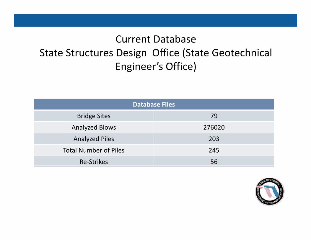
Current DatabaseState Structures Design Office (State Geotechnical
Engineer’s Office)
Database FilesDatabase Files
Bridge Sites 79
Analyzed Blows 276020
Analyzed Piles 203
Total Number of Piles 245
Re‐Strikes 56
Present Plan to Evaluate the Following:
• EDC costs will be partially offset by efficiencies from d fusing an increased resistance factor
• Speed of construction
• Reduce Pile Driving Claims
• Reduced Need for Verification Testing on Design‐Build Projects: Pile Capacity is verifiable without the normal verification testing associated with D/B.
S f t• Safety
Present Plan to Evaluate the Following (Contd):
• For projects with predetermined pile lengths, there will be ffi i i il i t ll ti d i i ti ill tmore efficiency in pile installation as driving operations will not
need to be interrupted for casting of production piles
• The Department will be monitoring and analyzing pile lengths and EDC cost to determine if there is a net savings or benefit to h Dthe Department.
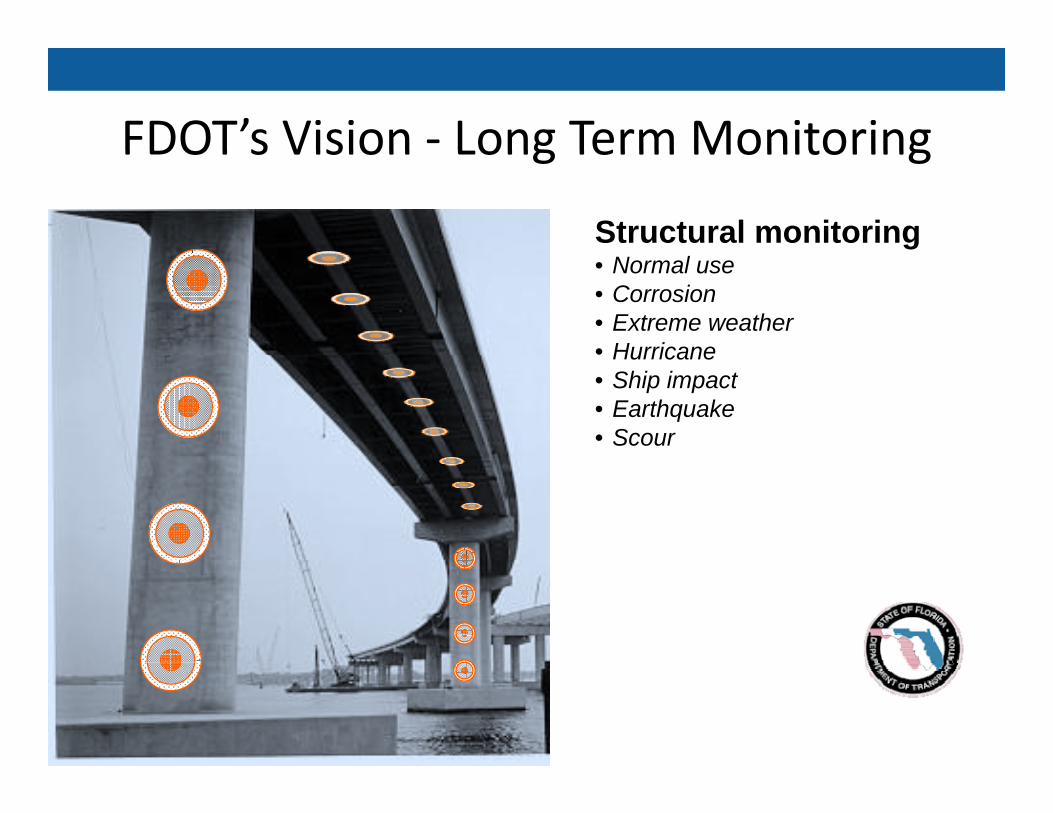
FDOT’s Vision ‐ Long Term MonitoringFDOT s Vision Long Term Monitoring
Structural monitoring• Normal use• Corrosion• Extreme weather• HurricaneHurricane• Ship impact• Earthquake• Scour
FDOT’s Long Term Monitoring Vision
• FDOT’s Vision is to monitor stresses in the foundations and other t t l l t h th b id i i istructural elements when the bridge is in‐service. – Assist the routine bridge inspection performed by FDOT.– Be able to remotely monitor stresses when over‐weight vehicles y gare permitted to use state highway
– Be able to monitor stresses on bridges in attempt to target enforcement relation to over‐weight vehicles similar to Virtualenforcement relation to over‐weight vehicles similar to Virtual Weigh‐in‐Motion.
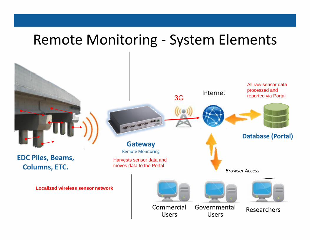
Remote Monitoring ‐ System ElementsRemote Monitoring System Elements
InternetAll raw sensor data processed and reported via Portal3G
Database (Portal)
EDC Piles, Beams, C l ETC
GatewayRemote Monitoring
Database (Portal)
Harvests sensor data and moves data to the PortalColumns, ETC. Browser Access
Localized wireless sensor network
moves data to the Portal
Commercial Users
ResearchersGovernmental Users
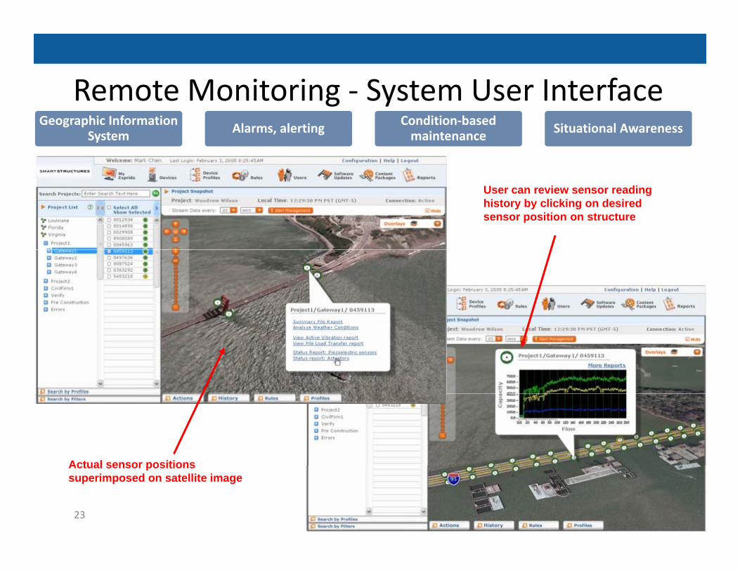
Remote Monitoring ‐ System User Interfaceg yGeographic Information
System Alarms, alerting Condition‐based maintenance Situational Awareness
User can review sensor reading history by clicking on desired sensor position on structure
Actual sensor positions
23
Actual sensor positions superimposed on satellite image
Thank You