Embed Size (px)
Citation preview
ACI 549.1R-93(Reapproved 1999)
This guide supplements two eArt Report of Ferrocement,Applications). It provides techselection, design criteria andtenance and repair procedurethe more effective use of ferrarchitects and engineers with cement, and provide owners orment to check the acceptabiliplication.
Keywords: admixtures; cements; materials; ferrocement; fibers; fleelasticity; reinforced concrete; reintension tests; welded wire fabric.
ACI Committee RepoCommentaries are intening, executing, or inspspecifications. Referenmade in the Project Ddocuments are desiredments, they should be incorporated into the
Guide for the Design, Construction, and Repair of Ferrocement
Reported by ACI Committee 549
Gordon B. Batson*Chairman
Perumalsamy N. Balaguru*Jose O. CastroAntonio J. GuerraMartin E. Iorns*
Colin D. JohnstonAntoine E. NaamanJames P. RomualdiSurendra P. Shah
Ronald F. Zollo*Secretary
(former Chairman) *Narayan SwamyBen L. TilsenRobert B. WilliamsonRogerio C. Zubieta
* Principal authorsThe following associate members of Committee 549 contributed to the preparation of this report: Shuaib H. Ahmad, Douglas Alexander, Antonio Nanni, Ricardo
P. Pama, P. Paramasivam, Sherwood P. Prawel, and Andrei M. Reinhorn.
Members of the Committee voting on the 1993 revisions:
P.N. BalaguruChairman
M. ArockiasamyNemkumar BanthiaGordon B. BatsonJose O. CastroJames I. DanielDavid M. GaleAntonio J. GuerraLloyd Hackman
Martin E. IornsColin D. JohnstonMohammad MansurJohn L MulderAntoine E. NaamanAntonio NanniD.V. ReddyJames P. Romualdi
Parviz SoroushianSecretary
Surendra P. ShahNarayan SwamyBen L. TilsenMethi WecharatanaRobert B. WilliamsonRobert C. ZellersRonald F. ZolloRogerio C. Zubieta
arlier publications (ACI 549R, State-of-the- and SP-61, Ferrocement-Materials andnical information on materials and material approaches, construction methods, main-s, and testing. The objectives are to promoteocement in terrestrial structures, providethe necessary tools to specify, and use ferro- their representutives with a reference docu-ty of ferrocement alternative in a given ap-
composite materials; construction; constructionxural strength, maintenance; metals; modulus offorcing materials; repairs; structural design;
CONTENTS
Chapter l-General, pg. 549.1R-2
rts, Guides, Standard Practices, andnded for guidance in designing, plan-ecting construction and in preparing
ces to these documents shall not beocuments. If items found in these
to be a part of the Project Docu-phrased in mandatory language andProject Documents.
549
l . l -Scope1.2-Approval to use procedures
Chapter 2-Terminology, pg. 549.lR-22.1-Reinforcement parameters2.2-Notation2.3-Definitions
Chapter 3-Materials, pg. 549.1R-43.1-Matrix3.2-Reinforcement
Chapter 4-Design, pg. 549.1R.84.1-Design methods4.2-Strength requirements4.3-Service load design4.4-Serviceability4.5-Particular design parameters
ACI 549.lR-93 supersedes ACI 549.1R-88 and became effective November 1,1993.
Copyright 0 1988, American Concrete Institute.All rights reserved including rights of reproduction and use in any form or by
any means, including the making of copies by any photo process, or by any elec-tronic or mechanical device, printed, written, or oral, or recording for sound orvisual reproduction or for use in any knowledge or retrieval system or device,unless permission in writing is obtained from the copyright proprietors.
.1R-l
549.1R-2 ACI COMMITTEE REPORT
4.6-Examples4.7-Design aids
Chapter 5-Fabrication, pg. 549.1R-115.1-General requirements5.2-Construction methods
Chapter 6-Maintenance and repair, pg. 549.lR-156.1-Introduction6.2-Blemish and stain removal6.3-Protective surface treatments6.4-Damage repair6.5-Repair materials6.6-Repair procedure
Chapter 7-Testing, pg. 549.lR-207.1-Test methods
Chapter 8-References, pg. 549.1R-228.1-Recommended references8.2-Cited references
Appendix A-Calculation of volume fraction of rein-forcement, pg. 549.1R-25
Appendix B-Flexural strength analysis of ferrocementsections, pg. 549.1R-25
Appendix C-SimpIified design aids, pg. 549,1R-28
Appendix D-Surface treatment for ferrocement struc-tures attacked by commonly used chemicals, pg. 549.1R-29
CHAPTER l-GENERAL
l.l-ScopeThis guide is based on technical information as-
sembled by ACI Committee 549, Ferrocement, from cur-rent practice, developments, and advances in the field offerrocement around the world. It represents a practicalsupplement to the state-of-the-art report (ACI 549R)published earlier by the committee. The guide coversmaterials for ferrocement, materials selection, and stan-dards; design criteria and approaches; construction meth-ods; maintenance and repair procedures; and testing.
The objectives of this guide are to promote the effec-tive use of ferrocement in terrestrial structures, providearchitects and engineers with the necessary tools to spe-cify and use ferrocement, and provide owners or their re-presentatives with a reference document to check theacceptability of a ferrocement alternative in a givenapplication. This guide is consistent with ACI BuildingCode Requirements for Reinforced Concrete (ACI 318)except for the special characteristics of ferrocement, suchas reinforcement cover and limits on deflection.
Ferrocement is a form of reinforced concrete using
closely spaced multiple layers of mesh and/or small-diameter rods completely infiltrated with, or encapsul-ated, in mortar. The most common type of reinforcementis steel mesh. Other materials such as selected organic,natural, or synthetic fibers may be combined with metal-lic mesh. This guide addresses only the use of steel rein-forcement in a hydraulic cement mortar matrix.
Applications of ferrocement are numerous, especiallyin structures or structural components where self-help orlow levels of skills are required. Besides boats andmarine structures, ferrocement is used for housing units,water tanks, grain silos, flat or corrugated roofing sheets,irrigation channels, and the like (see ACI 549R).
1.2-Approval for use in design and constructionUse of ferrocement and the procedures covered in this
guide may require approval by the authority or govern-mental agency having jurisdiction over the project.
CHAPTER 2-TERMINOLOGY
2.1-Reinforcing parametersThree parameters are commonly used in characterizing
the reinforcement in ferrocement applications: the vol-ume fraction, the specific surface of reinforcement, andthe effective modulus of the reinforcement.
2.1.1 Volume fraction of reinforcement Vf-Vf is thetotal volume of reinforcement divided by the volume ofcomposite (reinforcement and matrix). For a compositereinforced with meshes with square openings, Vf is equal-ly divided into Vfl and Vft for the longitudinal and trans-verse directions, respectively. For other types of rein-forcement, such as expanded metal, Vfl and Vft may beunequal. Examples of computation of Vf are shown inAppendix A.
2.1.2 Specific surface of reinforcement Sr-Sr is the totalbonded area of reinforcement (interface area or area ofthe steel that comes in contact with the mortar) dividedby the volume of composite. Sr is not to be confused withthe surface area of reinforcement divided by the volumeof reinforcement. For a composite using square meshes,Sr is divided equally into Srl and Srt in the longitudinaland transverse directions, respectively.
For a ferrocement plate of width b and depth h, thespecific surface of reinforcement can be computed from:
cS 0
=7
t bh (2-1)
in which x0 is the total surface area of bonded rein-forcement per unit length.
2.1.3 Relation between Sr and Vf-The relation betweenSr and Vf when square-grid wire meshes are used is
4 vS f=-f db
FERROCEMENT 549.1R-3
,
where db is the diameter of the wire. For other types ofreinforcement, such as expanded metal, Srl and Srt maybe unequal.
2.1.3 Effective modulus of the reinforcement-Althoughthe definitions of most ferrocement properties are thesame as for reinforced concrete, one property that maybe different is the effective modulus of the reinforcingsystem Er. This is because the elastic modulus of a mesh(steel or other) is not necessarily the same as the elasticmodulus of the filament (wire or other) from which it ismade. In a woven steel mesh, weaving imparts an undul-ating profile to the wires. When tested in tension, thewoven mesh made from these wires stretches more thana similar welded mesh made from identical straight wires.Hence, the woven mesh behaves as if it has a lower elas-tic modulus than that of the steel wires from which it ismade.
In addition, when a woven mesh is embedded in amortar matrix and tends to straighten under tension, thematrix resists the straightening, leading to a form oftension stiffening. A similar behavior occurs withexpanded metal mesh (lath) and hexagonal mesh. Toaccount for the above effects, the term “effective modulusof the reinforcing system” Er is used. For welded steelmeshes, Er may be taken equal to the elastic modulus ofthe steel wires; for other meshes, Er may be determinedfrom tensile tests on the ferrocement composite as ex-plained in Chapter 7. Design values for common meshesused in ferrocement are recommended in Chapter 4.
2.2-NotationA c =A =
S
Asi -
b =c =
d" =db =
d i=
cross-sectional area of ferrocement compositetotal effective cross-sectional area of rein-forcement in the direction considered
A, = f: Asii=l
effective cross-sectional area of reinforcementof mesh layer i in the direction consideredwidth of ferrocement sectiondistance from extreme compression fiber toneutral axisclear cover of mortar over first layer of meshdiameter or equivalent diameter of reinforce-ment useddistance from extreme compression fiber tocentroid of reinforcing layer ielastic modulus of mortar matrixelastic modulus of cracked ferrocement in ten-sion (slope of the stress-strain curve in thecracked elastic state)effective modulus of the reinforcing systemelastic modulus of steel reinforcementspecified compressive strength of mortarstress in reinforcing layer istrength of mesh reinforcement or reinforcingbars
f =Y
hM =nN =n N =nr =s =Sr =Srl =
S =rt
V =fVfi =
V =fl
V =ft
PI =
rl =
772 =
rlt =
rl@ =
c =cu
l . =CZ
Ey =
I:0 -
Q =
o- =cu
yield strength of mesh reinforcement or rein-forcing barsthickness of ferrocement sectionnominal moment strengthnominal tensile strengthnumber of layers of mesh; nominal resistancemodular ratio of reinforcementmesh opening or sizespecific surface of reinforcementspecific surface of reinforcement in the longi-tudinal directionspecific surface of reinforcement in the trans-verse directionvolumevolume
fractionfraction
of reinforcementof reinforcement for mesh
layer ivolume fraction of reinforcement in the longi-tudinal directionvolume fractionverse direction
of reinforcement in the trans-
factor defining depth of rectangular stressblock (ACI 318, Section 10.2.7.3)global efficiency factor of embedded rein-forcement in resisting tension or tensile-bending loadsvalue of q when the load or stress is appliedalong the longitudinal direction of the meshsystem or rod reinforcementvalue of q when the load or stress isS appliedalong the transverse direction of the mesh re-inforcement system or rod reinforcementvalue of 7 when the load or stress is appliedalong a direction forming an angle 0 with thelongitudinal directionultimate compressive strain of mortar (gener-ally assumed to be 0.003)strain of mesh reinforcement at layer i
J
nominal yield strain of mesh reinforcement =
VEtotal surface area of bonded reinforcementper unit lengthstress in ferrocement composite at yielding ofthe reinforcementstress in ferrocement composite at ultimatestrength in tension
2.3-DefinitionsThe following terms are defined because they do not
appear in ACI 116R, Cement and Concrete Terminologyor have another meaning as applied to ferrocement.
Armature-The total reinforcement system or skeletalreinforcement and mesh for a ferrocement boat.
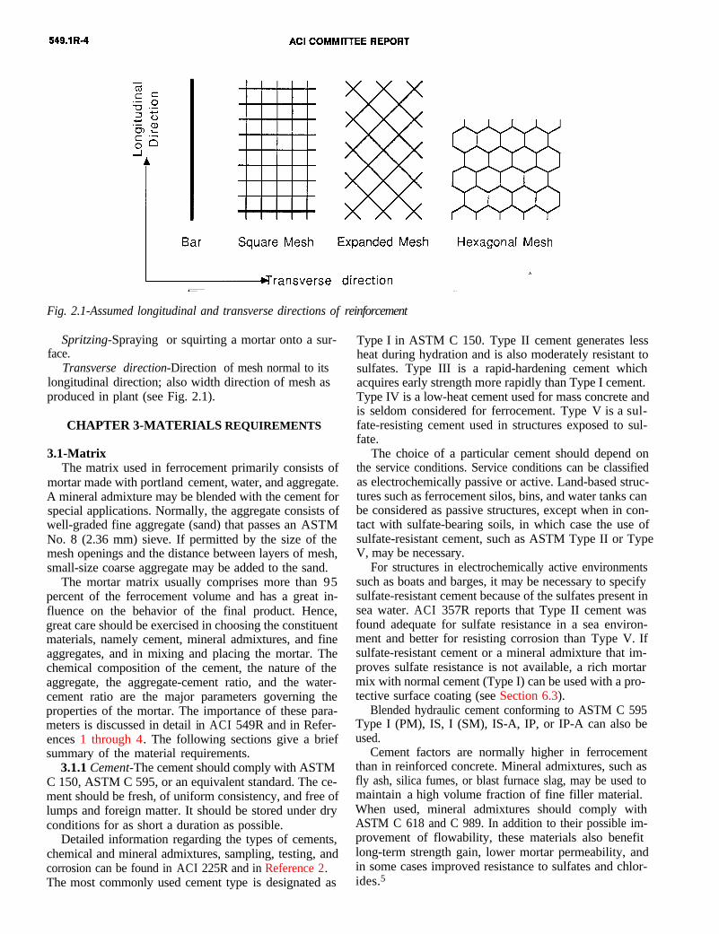
Longitudinal direction-The roll direction (longerdirection) of the mesh as produced in plant (see Fig.2.1).
Skeletal reinforcement-A planar framework of widelyspaced tied steel bars that provides shape and support forlayers of mesh or fabric attached to either side.
Spritzing-Spraying or squirting a mortar onto a sur-face.
Transverse direction-Direction of mesh normal to itslongitudinal direction; also width direction of mesh asproduced in plant (see Fig. 2.1).
Fig. 2.1-Assumed longitudinal and transverse directions of reinforcement
CHAPTER 3-MATERIALS REQUIREMENTS
3.1-MatrixThe matrix used in ferrocement primarily consists of
mortar made with portland cement, water, and aggregate.A mineral admixture may be blended with the cement forspecial applications. Normally, the aggregate consists ofwell-graded fine aggregate (sand) that passes an ASTMNo. 8 (2.36 mm) sieve. If permitted by the size of themesh openings and the distance between layers of mesh,small-size coarse aggregate may be added to the sand.
The mortar matrix usually comprises more than 95percent of the ferrocement volume and has a great in-fluence on the behavior of the final product. Hence,great care should be exercised in choosing the constituentmaterials, namely cement, mineral admixtures, and fineaggregates, and in mixing and placing the mortar. Thechemical composition of the cement, the nature of theaggregate, the aggregate-cement ratio, and the water-cement ratio are the major parameters governing theproperties of the mortar. The importance of these para-meters is discussed in detail in ACI 549R and in Refer-ences 1 through 4. The following sections give a briefsummary of the material requirements.
3.1.1 Cement-The cement should comply with ASTMC 150, ASTM C 595, or an equivalent standard. The ce-ment should be fresh, of uniform consistency, and free oflumps and foreign matter. It should be stored under dryconditions for as short a duration as possible.
Detailed information regarding the types of cements,chemical and mineral admixtures, sampling, testing, andcorrosion can be found in ACI 225R and in Reference 2.The most commonly used cement type is designated as
Type I in ASTM C 150. Type II cement generates lessheat during hydration and is also moderately resistant tosulfates. Type III is a rapid-hardening cement whichacquires early strength more rapidly than Type I cement.Type IV is a low-heat cement used for mass concrete andis seldom considered for ferrocement. Type V is a sul-fate-resisting cement used in structures exposed to sul-fate.
The choice of a particular cement should depend onthe service conditions. Service conditions can be classifiedas electrochemically passive or active. Land-based struc-tures such as ferrocement silos, bins, and water tanks canbe considered as passive structures, except when in con-tact with sulfate-bearing soils, in which case the use ofsulfate-resistant cement, such as ASTM Type II or TypeV, may be necessary.
For structures in electrochemically active environmentssuch as boats and barges, it may be necessary to specifysulfate-resistant cement because of the sulfates present insea water. ACI 357R reports that Type II cement wasfound adequate for sulfate resistance in a sea environ-ment and better for resisting corrosion than Type V. Ifsulfate-resistant cement or a mineral admixture that im-proves sulfate resistance is not available, a rich mortarmix with normal cement (Type I) can be used with a pro-tective surface coating (see Section 6.3).
Blended hydraulic cement conforming to ASTM C 595Type I (PM), IS, I (SM), IS-A, IP, or IP-A can also beused.
Cement factors are normally higher in ferrocementthan in reinforced concrete. Mineral admixtures, such asfly ash, silica fumes, or blast furnace slag, may be used tomaintain a high volume fraction of fine filler material.When used, mineral admixtures should comply withASTM C 618 and C 989. In addition to their possible im-provement of flowability, these materials also benefitlong-term strength gain, lower mortar permeability, andin some cases improved resistance to sulfates and chlor-ides.5
DESIGN, CONSTRUCTION, AND REPAIR OF FERROCEMENT 549.1R-5
3.1.2 Aggregates-Normal-weight fine aggregate (sand)is the most common aggregate used in ferrocement. Itshould comply with ASTM C 33 requirements (for fineaggregate) or an equivalent standard. It should be clean,inert, free of organic matter and deleterious substances,and relatively free of silt and clay. Hard, strong, andsharp silica aggregates achieve the best strength results.Sharp sand may, however, cause pumping problems thatmay outweigh the slight gain in strength over roundedgrains.
The grading of fine aggregate should be in accordancewith the guidelines of Table 3.1, which are adapted fromASTM C 33; however, the maximum particle size shouldbe controlled by construction constraints such as meshsize and distance between layers. It is generally agreedthat a maximum particle size passing sieve No. 16 (1.18mm) is appropriate in most applications. Uniformgrading is desirable to achieve a workable high-densitymortar mix, but trial-tested gap-graded mortars can alsobe used.6,7
Table 3.1-Guidelines for grading of sand
Sieve size, U.S.standard square mesh
No. 8 (2.36 mm)No. 16 (1.18 mm)No. 30 (0.60 mm)No. 50 (0.30 mm)No. 100 (0.15 mm)
Percent passing byweight
80-10050-8525-6010-302-10
Aggregates that react with the alkalis in cement shouldbe avoided. When aggregates may be reactive, theyshould be tested in accordance with ASTM C 227. Ifproven reactive, the use of a pozzolan to suppress thereactivity should be considered and evaluated in accor-dance with ASTM C 441.
Lightweight fine aggregates can also be used for fer-rocement. They should comply with the requirements forfine aggregate given in ASTM C 330. Volcanic ash, blastfurnace slag, expanded shale fines, perlite, pumice, ver-miculite, and inert alkali-resistant plastics may be suitableas lightweight aggregates. The use of lightweight aggre-gates instead of normal weight aggregates leads to a re-duction in the strength of the mortar. Hence correspon-ding adjustments may be needed in the structural design.
3.13 Water-The mixing water should be fresh, clean,and potable. The water should be relatively free fromorganic matter, silt, oil, sugar, chloride, and acidicmaterial. Ittion in the
should have apHr 7 to minimize thepH of the mortar slurry. Salt water
reduc-
acceptable, but chlorinated drinking water can be used.3.1.4 Admixtures-Chemical admixtures used in ferro-
is not
cement servereduction, whbility; improvement in impermeability; air entrainment,which increases resistance to freezing and thawing; and
one of the following four purposes: waterich increases strength and reduces permea-
suppression of reaction between galvanized reinforcementand cement.1
Conventional and high-range water-reducing admix-tures (superplasticizers) should conform to ASTM C 494.The use of water-reducing admixtures permits an in-crease in sand content for the same design strength or adecrease in water content creases in water content
for the same workability. De-result in lower shrinkage and
less surface crazing. Retarders are used in large time-consuming plastering projects, especially in hot weatherconditions.
If watertightness is important, such as in water-- orliquid-retaining structures, special precautions must betaken. To achieve watertightness, the water-cement ratioshould preferably be kept below 0.4, crack widths limited(see Chapter 4) and, if necessary, waterproofing coatingsapplied8 (see Section 6.3.3).
Mineral admixtures such as fly ash (ASTM C 618) canbe added to the cement to increase workability and dura-bility. Normally, 15 percent of the cement can bereplaced with mineral admixtures without appreciably re-ducing the strength. Unlike conventional cement mortars,the pozzolanic admixtures are not added to reduce ce-ment but to replace part of the fine aggregates to im-prove plasticity. The tendency for some natural poz-zolans to absorb water and thus adversely affect hydra-tion of the cement phase should be checked by measur-ing the water of absorption. Adding silica fume isreported to reduce porosity and improve strength, per-meability, and durability;5 however, little experienceexists so far in using silica fumes in ferrocement. Plas-tering may be hindered by an excessive amount of silicafume, which may render the mix stickier.
Air-entraining admixtures conforming to ASTM C 260can be used to increase resistance to freezing and thaw-ing. To insure good resistance to freezing and thawing,the air content should be consistent with the require-ments of ACI 201.2R.
A quality matrix can be obtained without using anyadmixtures if experience has shown its applicability. Inspecial exposure situations, admixtures (Section 6.5.2) orcoatings (Section 6.3.3) should be used to improve ser-viceability.
Other admixtures not covered in ASTM standards arenot recommended.
3.1.5 Mix proportioning-The ranges of mix propor-tions recommended for common ferrocement applica-tions are: sand-cement ratio by weight, 1.5 to 2.5, andwater-cement ratio by weight, 0.35 to 0.5. The higher thesand content, the higher the required water content tomaintain the same workability. Fineness modulus of thesand, water-cement ratio, and sand-cement ratio shouldbe determined from trial batches to insure a mix that caninfiltrate (encapsulate)) the mesh and develop a strongand dense matrix. Shrinkage is not a problem in ferro-cement because of the high reinforcement content.Instead, in ferrocement mortars it is most important tomaintain plasticity as a design criterion.
549.1R-6 ACI C OMMITTEE REPORT
The moisture content of the aggregate should be con-sidered in the calculation of required water. Quantities ofmaterials should preferably be determined by weight.
The mix should be as stiff as possible, provided it doesnot prevent full penetration of the mesh. Normally theslump of fresh mortar should not exceed 2 in. (50 mm).For most applications, the 28-day compressive strength of3 by 6-m. (75 by 150-mm) moist-cured cylinders shouldnot be less than 5000 psi (35 MPa).
3.2-ReinforcementThe reinforcement should be clean and free from
deleterious materials such as dust, loose rust, coating ofpaint, oil, or similar substances.
Wire mesh with closely spaced wires is the mostcommonly used reinforcement in ferrocement. Expandedmetal, welded-wire fabric, wires or rods, prestressiugtendons and discontinuous fibers are also being used inspecial applications or for reasons of performance oreconomy.
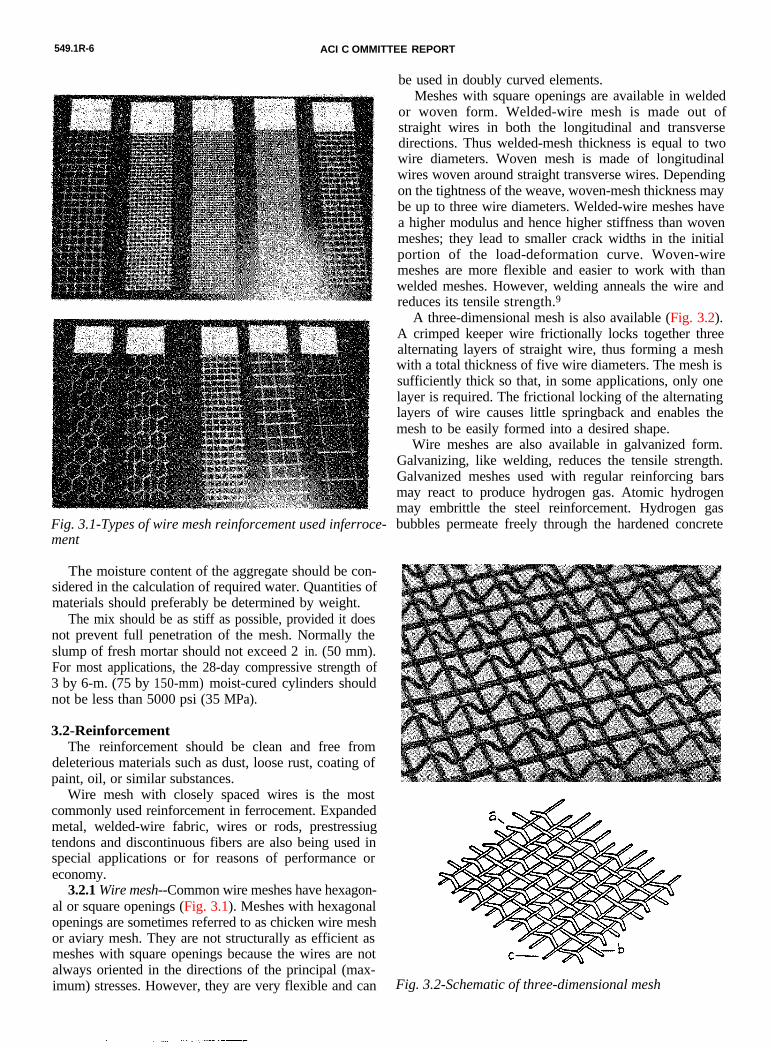
3.2.1 Wire mesh--Common wire meshes have hexagon-al or square openings (Fig. 3.1). Meshes with hexagonalopenings are sometimes referred to as chicken wire meshor aviary mesh. They are not structurally as efficient asmeshes with square openings because the wires are notalways oriented in the directions of the principal (max-imum) stresses. However, they are very flexible and can
be used in doubly curved elements.
Fig. 3.1-Types of wire mesh reinforcement used inferroce- ment
Meshes with square openings are available in weldedor woven form. Welded-wire mesh is made out ofstraight wires in both the longitudinal and transversedirections. Thus welded-mesh thickness is equal to twowire diameters. Woven mesh is made of longitudinalwires woven around straight transverse wires. Dependingon the tightness of the weave, woven-mesh thickness maybe up to three wire diameters. Welded-wire meshes havea higher modulus and hence higher stiffness than wovenmeshes; they lead to smaller crack widths in the initialportion of the load-deformation curve. Woven-wiremeshes are more flexible and easier to work with thanwelded meshes. However, welding anneals the wire andreduces its tensile strength.9
A three-dimensional mesh is also available (Fig. 3.2).A crimped keeper wire frictionally locks together threealternating layers of straight wire, thus forming a meshwith a total thickness of five wire diameters. The mesh issufficiently thick so that, in some applications, only onelayer is required. The frictional locking of the alternatinglayers of wire causes little springback and enables themesh to be easily formed into a desired shape.
Fig. 3.2-Schematic of three-dimensional mesh
Wire meshes are also available in galvanized form.Galvanizing, like welding, reduces the tensile strength.Galvanized meshes used with regular reinforcing barsmay react to produce hydrogen gas. Atomic hydrogenmay embrittle the steel reinforcement. Hydrogen gasbubbles permeate freely through the hardened concrete
DESIGN, CONSTRUCTION, AND REPAIR OF FERROCEMENT 549.1R-7
and may have an adverse effect on the matrix strengthand permeability particularly at the interface of the rein-forcement. As suggested in Reference 10, this reactioncan be passivated by adding chromium trioxide to themixing water in proportion of about 300 parts per millionby weight of mortar. However, a substantially smallerproportion may be sufficient to prevent hydrogen evolu-tion.1 Epoxy-coated mesh may be substituted for galvan-ized mesh.
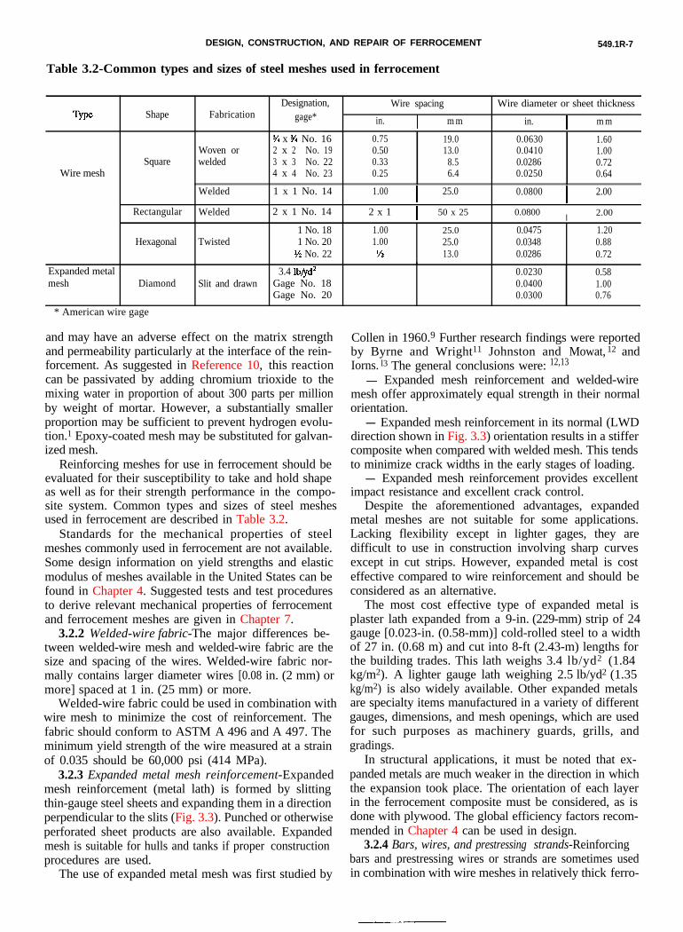
Reinforcing meshes for use in ferrocement should beevaluated for their susceptibility to take and hold shapeas well as for their strength performance in the compo-site system. Common types and sizes of steel meshesused in ferrocement are described in Table 3.2.
Table 3.2-Common types and sizes of steel meshes used in ferrocement
Designation,gage*
Wire spacing Wire diameter or sheet thicknessFabricationShape
in. I m m in. I m m
% x % No. 16 0.75 19.0 0.0630 1.602 x 2 No. 19 0.50 13.0 0.0410 1.003 x 3 No. 22 0.33 8.5 0.0286 0.724 x 4 No. 23 0.25 6.4 0.0250 0.64
Woven orweldedSquare
Wire mesh
Welded 1.00I
25.0 0.0800I
2.001 x 1 No. 14
2 x 1 I 50 x 25 0.0800I 2.000Rectangular Welded 2 x 1 No. 14
1 No. 181 No. 20
l% No. 22
1.00 25.0 0.0475 1.201.00 25.0 0.0348 0.88
lY2 13.0 0.0286 0.72TwisteddHexagonal
Expanded metalmesh
3.4 lb/yd’Gage No. 18Gage No. 20
0.0230 0.580.0400 1.000.0300 0.76
Diamond Slit and drawn
* American wire gage
Standards for the mechanical properties of steelmeshes commonly used in ferrocement are not available.Some design information on yield strengths and elasticmodulus of meshes available in the United States can befound in Chapter 4. Suggested tests and test proceduresto derive relevant mechanical properties of ferrocementand ferrocement meshes are given in Chapter 7.
3.2.2 Welded-wire fabric-The major differences be-tween welded-wire mesh and welded-wire fabric are thesize and spacing of the wires. Welded-wire fabric nor-mally contains larger diameter wires [0.08 in. (2 mm) ormore] spaced at 1 in. (25 mm) or more.
Welded-wire fabric could be used in combination withwire mesh to minimize the cost of reinforcement. Thefabric should conform to ASTM A 496 and A 497. Theminimum yield strength of the wire measured at a strainof 0.035 should be 60,000 psi (414 MPa).
3.2.3 Expanded metal mesh reinforcement-Expandedmesh reinforcement (metal lath) is formed by slittingthin-gauge steel sheets and expanding them in a directionperpendicular to the slits (Fig. 3.3). Punched or otherwiseperforated sheet products are also available. Expandedmesh is suitable for hulls and tanks if proper constructionprocedures are used.
Collen in 1960.9 Further research findings were reportedby Byrne and Wright11 Johnston and Mowat, 12 andIorns. l3 The general conclusions were: 12,13
- Expanded mesh reinforcement and welded-wiremesh offer approximately equal strength in their normalorientation.- Expanded mesh reinforcement in its normal (LWD
direction shown in Fig. 3.3) orientation results in a stiffercomposite when compared with welded mesh. This tendsto minimize crack widths in the early stages of loading.- Expanded mesh reinforcement provides excellent
impact resistance and excellent crack control.Despite the aforementioned advantages, expanded
metal meshes are not suitable for some applications.Lacking flexibility except in lighter gages, they aredifficult to use in construction involving sharp curvesexcept in cut strips. However, expanded metal is costeffective compared to wire reinforcement and should beconsidered as an alternative.
The most cost effective type of expanded metal isplaster lath expanded from a 9-in. (229-mm) strip of 24gauge [0.023-in. (0.58-mm)] cold-rolled steel to a widthof 27 in. (0.68 m) and cut into 8-ft (2.43-m) lengths forthe building trades. This lath weighs 3.4 lb/yd2 (1.84kg/m2). A lighter gauge lath weighing 2.5 lb/yd2 (1.35kg/m2) is also widely available. Other expanded metalsare specialty items manufactured in a variety of differentgauges, dimensions, and mesh openings, which are usedfor such purposes as machinery guards, grills, andgradings.
In structural applications, it must be noted that ex-panded metals are much weaker in the direction in whichthe expansion took place. The orientation of each layerin the ferrocement composite must be considered, as isdone with plywood. The global efficiency factors recom-mended in Chapter 4 can be used in design.
3.2.4 Bars, wires, and prestressing strands-Reinforcingbars and prestressing wires or strands are sometimes usedin combination with wire meshes in relatively thick ferro-
The use of expanded metal mesh was first studied by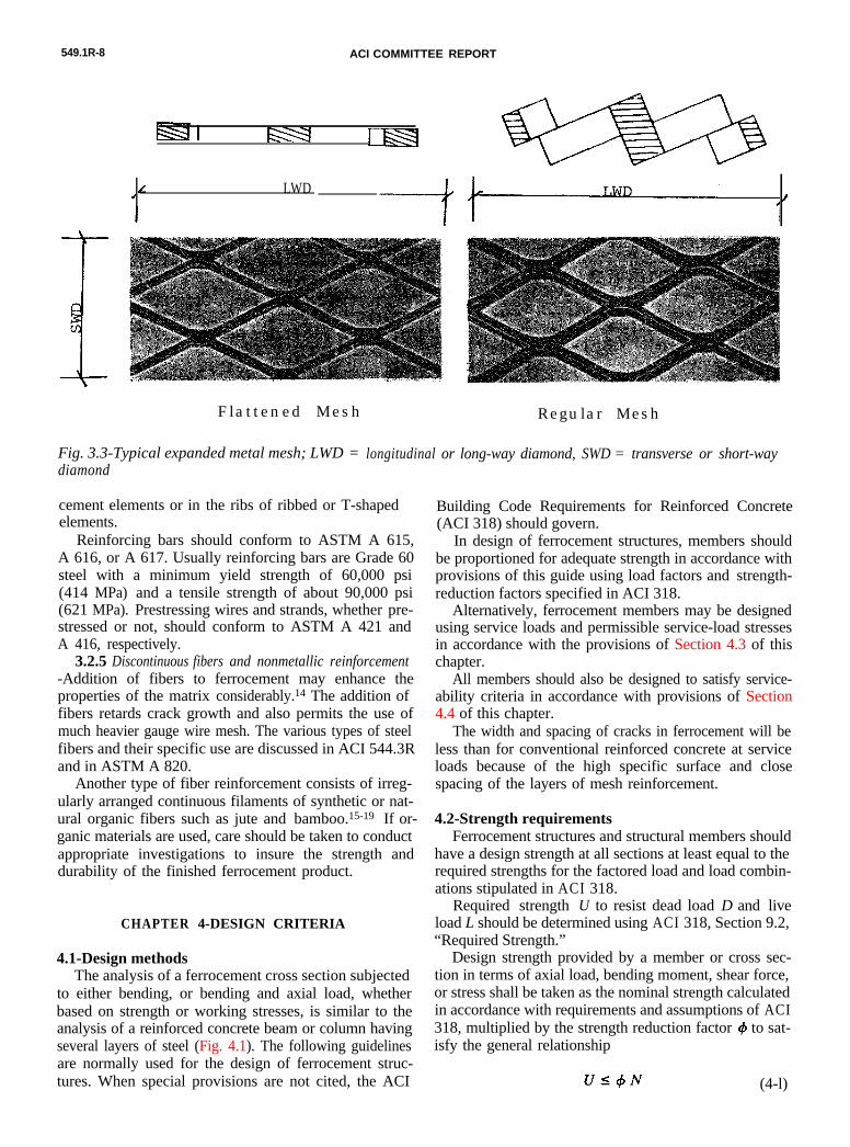
549.1R-8 ACI COMMITTEE REPORT
I Ilsq
/ LWD*I/
Flattened Mesh Regular Mesh
Fig. 3.3-Typical expanded metal mesh; LWD = longitudinal or long-way diamond, SWD = transverse or short-waydiamond
cement elements or in the ribs of ribbed or T-shapedelements.
Reinforcing bars should conform to ASTM A 615,A 616, or A 617. Usually reinforcing bars are Grade 60steel with a minimum yield strength of 60,000 psi(414 MPa) and a tensile strength of about 90,000 psi(621 MPa). Prestressing wires and strands, whether pre-stressed or not, should conform to ASTM A 421 andA 416, respectively.
3.2.5 Discontinuous fibers and nonmetallic reinforcement-Addition of fibers to ferrocement may enhance theproperties of the matrix considerably.14 The addition offibers retards crack growth and also permits the use ofmuch heavier gauge wire mesh. The various types of steelfibers and their specific use are discussed in ACI 544.3Rand in ASTM A 820.
Another type of fiber reinforcement consists of irreg-ularly arranged continuous filaments of synthetic or nat-ural organic fibers such as jute and bamboo.15-19 If or-ganic materials are used, care should be taken to conductappropriate investigations to insure the strength anddurability of the finished ferrocement product.
CHAPTER 4-DESIGN CRITERIA
4.1-Design methodsThe analysis of a ferrocement cross section subjected
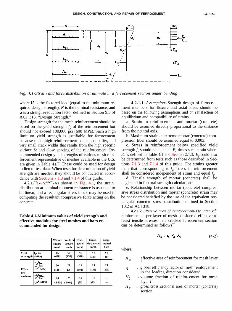
to either bending, or bending and axial load, whetherbased on strength or working stresses, is similar to theanalysis of a reinforced concrete beam or column havingseveral layers of steel (Fig. 4.1). The following guidelinesare normally used for the design of ferrocement struc-tures. When special provisions are not cited, the ACI
Building Code Requirements for Reinforced Concrete(ACI 318) should govern.
In design of ferrocement structures, members shouldbe proportioned for adequate strength in accordance withprovisions of this guide using load factors and strength-reduction factors specified in ACI 318.
Alternatively, ferrocement members may be designedusing service loads and permissible service-load stressesin accordance with the provisions of Section 4.3 of thischapter.
All members should also be designed to satisfy service-ability criteria in accordance with provisions of Section4.4 of this chapter.
The width and spacing of cracks in ferrocement will beless than for conventional reinforced concrete at serviceloads because of the high specific surface and closespacing of the layers of mesh reinforcement.
4.2-Strength requirementsFerrocement structures and structural members should
have a design strength at all sections at least equal to therequired strengths for the factored load and load combin-ations stipulated in ACI 318.
Required strength U to resist dead load D and liveload L should be determined using ACI 318, Section 9.2,“Required Strength.”
Design strength provided by a member or cross sec-tion in terms of axial load, bending moment, shear force,or stress shall be taken as the nominal strength calculatedin accordance with requirements and assumptions of ACI318, multiplied by the strength reduction factor # to sat-isfy the general relationship
Us+N (4-l)
DESIGN, CONSTRUCTION, AND REPAIR OF FERROCEMENT 549.1R-9
where U is the factored load (equal to the minimum re-quired design strength), N is the nominal resistance, and4 is a strength-reduction factor defined in Section 9.3 ofACI 318, “Design Strength.”
Design strength for the mesh reinforcement should bebased on the yield strength fy of the reinforcement butshould not exceed 100,000 psi (690 MPa). Such a highlimit on yield strength is justifiable for ferrocementbecause of its high reinforcement content, ductility, andvery small crack widths that results from the high specificsurface Sr and close spacing of the reinforcement. Re-commended design yield strengths of various mesh rein-forcement representative of meshes available in the U.S.are given in Table 4.1.20) These could be used for designin lieu of test data. When tests for determination of yieldstrength are needed, they should be conducted in accor-dance with Sections 7.1.3 and 7.1.4 of this guide.
4.2.1 Flexure20-23-As shown in Fig. 4.1, the straindistribution at nominal moment resistance is assumed tobe linear, and a rectangular stress block may be used incomputing the resultant compressive force acting on theconcrete.
h
,003
t-i.85f’k-4
= 4/dCL-_ -I-----__- d
. .
ccFCS,
Ts2
---tTs3
>Ts 4
-
Fig. 4.1-Strain and force distribution at ultimate in a ferrocement section under bending
Table 4.1-Minimum values of yield strength andeffective modulus for steel meshes and bars re-commended for design
Woven Welded Hexa- Expan- Longi-square square gonal de-d metal tudinalmesh mesh mesh mesh bars
Yield fv, ksis trength (MPa)
0%~~.103 ksi
Effec- (Id MPa)tive .modulus Q%WU.
lo3 ksi(103 MPa)
65 65 45 45 60(450) (450) (310) (310) (414)
20 29 15 20 29
(138) (200) (104) (138) (200)
24 29 10 10 -
( 1 6 5 ) ( 2 0 0 ) (69) (69) -
4.2.1.1 Assumptions-Strength design of ferroce-ment members for flexure and axial loads should bebased on the following assumptions and on satisfaction ofequilibrium and compatibility of strains.
a. Strain in reinforcement and mortar (concrete)should be assumed directly proportional to the distancefrom the neutral axis.
b. Maximum strain at extreme mortar (concrete) com-pression fiber should be assumed equal to 0.003.
c. Stress in reinforcement below specified yieldstrength fy should be taken as Er times steel strain whereEr is defined in Table 4.1 and Section 2.1.3. Er could alsobe determined from tests such as those described in Sec-tions 7.1.3 and 7.1.4 of this guide. For strains greaterthan that corresponding to fy, stress in reinforcementshall be considered independent of strain and equal fy.
d. Tensile strength of mortar (concrete) shall beneglected in flexural strength calculations.
e. Relationship between mortar (concrete) compres-sive stress distribution and mortar (concrete) strain maybe considered satisfied by the use of the equivalent rec-tangular concrete stress distribution defined in Section10.2 of ACI 318.
4.2.1.2 Effective area of reinforcement-The area ofreinforcement per layer of mesh considered effective toresist tensile stresses in a cracked ferrocement sectioncan be determined as follows20
where:
A Si=
r7 =
V =F
A c =
Ad = tl vfl A, (4-2)
effective area of reinforcement for mesh layeri
global efficiency factor of mesh reinforcementin the loading direction consideredvolume fraction of reinforcement for meshlayer igross cross sectional area of mortar (concrete)section
549.1R-10
The global efficiency factor q, when multiplied by thevolume fraction of reinforcement, gives the equivalentvolume fraction (or equivalent reinforcement ratio) inthe loading direction considered. In effect, it leads to anequivalent (effective) area of reinforcement per layer ofmesh in that loading direction. For square meshes, 71 isequal to 0.5 when loading is applied in one of the princi-pal directions. For a reinforcing bar loaded along its axis,77 = 1.
Some information on the derivations of r) and onother concepts concerning efficiency factors can be foundin References 12, 24, and 25. In lieu of the values de-rived from tests for a particular mesh system, the valuesof 7 given in Table 4.220 for common types of reinforce-ment and loading directions can be used. The global effi-ciency factor applies whether the reinforcement is in thetension or the compression zones of the member. Defin-itions of reinforcement directions are illustrated in Fig.2.1
Table 4.2-Recommended design values of the global ef-ficiency factor 77 of reinforcement for a member in uni-axial tension or bending
Longitudinal 0.50 0.50 0.45 0.65 1Global qIeffi-ciency Transverse q1 0.50 0.50 0.30 0.20 0
factor At 45 deg, 70 0.35 0.35 0.30 0.30 0.70
Note that the value of vt = 0.2 for expanded metalmesh (Table 4.2) may not always be conservative, parti-cularly in thicker sections in flexure with the meshoriented in the SWD (short way diamond).26 The valuesin Table 4.2 should be used for sections 2 in. (50 mm) orless in thickness, and tests conducted for global efficiencyvalues for sections of 2 in. (50 mm) in thickness.
4.2.2 Tension 27-29-The nominal resistance of crackedferrocement elements subjected to pure tensile loadingcan be approximated by the load-carrying capacity of themesh reinforcement alone in the direction of loading.The following procedure may be used
Nn= syAf (4-3)
N =n nominal tensile load resistance in directionconsidered
A =s effective cross-sectional area of reinforcementin direction considered
fy = yield stress of mesh reinforcement
The value of As is given by
I3*= _ Asii=1 (4-4)
where
N =A si =
number of mesh layerseffective area of reinforcement for mesh layeri (Eq. 4-2)
4.2.3 Compression-As a first approximation, the nom-inal resistance of ferrocement sections subjected to uni-axial compression can be derived from the load-carryingcapacity of the unreinforced mortar (concrete) matrixassuming a uniform stress distribution of 0.85 fc’, wherefc’ is the design compressive strength of the mortar ma-trix. However, the transverse component of the reinforce-ment can contribute additional strength when square orrectangular wire meshes are used, while expanded meshcontributes virtually no strengtheningachieved by the mortar alone.12
beyond thatSlenderness effects of
thin sections, which can reduce the load-carrying capacitybelow that based on the design compressive strength,should be considered.
4.2.4 Shear-No test data are available on the shearcapacity of ferrocement slabs or beams in flexure.
4.3-Service load design4.3.1 Flexure-for investigation of stresses at service
loads, straight-line theory (for flexure) shall be used withthe following assumptions.
a. Strains vary linearly with the distance from theneutral axis.
b. Stress-strain relationships of mortar (concrete) andreinforcement are linear for stresses less than or equal topermissible service load stresses.
c. Mortar (concrete) resists no tension.d. Perfect bond exists between steel and mortar (con-
crete).To compute stresses and strains for a given loading,
the cracked transformed section can be used. The effec-tive area of each layer of mesh reinforcement should bedetermined from Eq. (4-2). The same value of modularratio, nr,= Er/Ec, is commonly used for both tensile andcompressive reinforcement. Recommended design valuesof Er are given in Table 4.1. Once that neutral axis isdetermined, the analysis proceeds as for reinforced con-crete beams or columns having several layers of steel andsubjected to pure bending.
4.3.1.1 Allowable tensile stress-The allowable tensilestress in the mesh reinforcement under service conditionsmay generally be taken as 0.60 fy where fy is the yieldstrength. Values of fy given in Table 4.1 are representa-tive of steel meshes available in the United States andmay be used for design. Tests to determine fy for a par-ticular mesh system are described in Chapter 7. Forliquid retaining and sanitary structures (refer to ACI350R), it is preferable to limit the allowable tensile stressto 30 ksi (207 MPa). Consideration can be given to in-creasing the allowable tensile stresses if crack-widthmeasurements on a model test indicate that a higherstress will not impair performance.
DESIGN, CONSTRUCTION, AND REPAIR OF FERROCEMENT 549.1R-11
4.3.1.2 Allowable compressive stress-The allowablecompressive stress in either the mortar (concrete) or theferrocement composite may be taken as 0.45 fc’ where6is the specified compressive strength of the mortar. Mea-surements of the mortar compressive strength may be ob-tained from tests on 3 x 6-in. (76 x 152-mm) cylinders.
4.4-ServiceabilityFerrocement members and structures should as a min-
imum meet the intent of the serviceability requirementsof ACI 318 except for the concrete cover.
4.4.1 Crack-width limitations-It is recommended thatthe maximum value of crack width under service loadconditions be less than 0.004 in. (0.10 mm) for non-corrosive environments and 0.002 in. (0.05 mm) for cor-rosive environments and/or water-retaining structures.23,30
It should be noted that the recommended crack widthsare smaller for ferrocement than values suggested by ACI318. Crack widths may be measured from model tests ortheir values may be estimated using acceptable predictionequations such as those recommended in ACI 549R orReference 31.
4.4.2 Fatigue stress range-For ferrocement structuresto sustain a minimum fatigue life of two million cycles,the stress range in the reinforcement must be limited to30 ksi (207 MPa). A stress range of 36 ksi (348 MPa)may be used for one million cycles.32 Higher values maybe considered if justified by tests.
4.4.3 Corrosion durability-Particular care should betaken to insure a durable mortar matrix and optimize theparameters that reduce the risk of corrosion (see alsoSection 3.1.4 of this report).
4.4.4 Deflection limitation-Because ferrocement inthin sections is very flexible and its design is very likelyto be controlled by criteria other than deflection, noparticular deflection limitation is recommended.
4.5-Particular design parametersa. The cover of the reinforcement should be about
twice the diameter of the mesh wire or thickness of otherreinforcement used. However, a smaller cover is accep-table provided the reinforcement is not susceptible torapid corrosion, the surface is protected by an appro-priate coating, and the crack width is limited to 0.002 in.(0.05 mm). For ferrocement elements of thickness lessthan one in. (25 mm), a cover of the order of 0.08 in.(2 mm) has given satisfactory results.
b. For a given ferrocement cross section of totalthickness h, the recommended mesh openings should notbe larger than h.
c. For nonprestressed water-retaining structures thetotal volume fraction of reinforcement should not be lessthan about 3.5 percent and the total specific surface ofreinforcement should not be less than 4 in.2/in.3
(0.16 mm2/mm3).d. In computing the specific surface of the reinforce-
ment, the contribution of fibers added to the matrix maybe considered while the fiber contribution may be ig-
nored in computing the volume fraction of reinforce-ment.
e. If skeletal reinforcement (see definition in Section5.2.1) is used, it is recommended that the skeletal rein-forcement not occupy more than 50 percent of the thick-ness of the ferrocement composite.
f. For a given volume fraction of reinforcement, betterperformance-not in terms of strength, but in terms ofcrack widths, water-tightness, and ductility-can beachieved by uniformly distributing the reinforcementthroughout the thickness33,34 and by increasing its specificsurface. While for certain applications, a minimum of twolayers of mesh would be acceptable, the advantages offerrocement are mostly realized when more than twolayers are used.
4.6-ExamplesTypical examples for the analysis and design of ferro-
cement flexural elements in accordance with the proce-dures described in this chapter are provided in AppendixB.
4.7-Design aidsThe computation of the nominal moment strength of
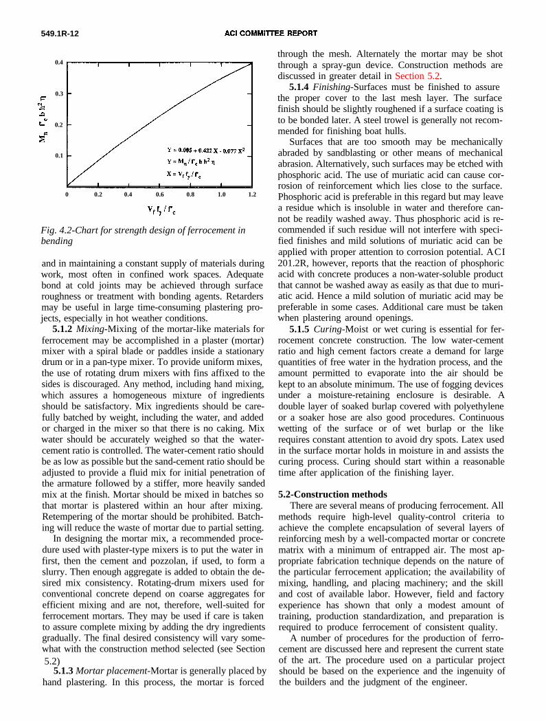
ferrocement sections (as illustrated in Appendix B) canbe time-consuming unless a computer is used. Followingan extensive corn uterized parametric evaluation, Naa-man and Homrich20 derived the following nondimension-al equation to predict the nominal moment strength offerrocement beams subjected to pure bending
A design graph representing Eq. (4-5) is given in Fig.4.2. In developing these design aids the net mortar coverto the first layer of mesh was assumed equal to 0.06 in.(1.5 mm), a minimum of two mesh layers was consideredthroughout, and when more than two layers of meshwere used they were assumed equally spaced. The appli-cation of Eq. (4-5) and Fig. 4.2 to the examples ofAppendix B is illustrated in Appendix C.
CHAPTER 5-FABRICATION
5.1-General requirementsThe materials used in ferrocement production and
their selection have already been discussed in Chapter 3of this report. This chapter discusses the mixing, placing,and handling of materials used in ferrocement construc-tion.
5.1.1 Planning-It is generally believed that for anyfabrication method with ferrocement, plastering has to becontinuous through the completion of the job. This mayrequire a large number of workers involved in plastering
549.1R-12
0.4
0.3F
‘yr:a
b” 0.2E
E
0.1
0 0.2 0.4 0.6 0.8 1.0 1.2
Fig. 4.2-Chart for strength design of ferrocement inbending
and in maintaining a constant supply of materials duringwork, most often in confined work spaces. Adequatebond at cold joints may be achieved through surfaceroughness or treatment with bonding agents. Retardersmay be useful in large time-consuming plastering pro-jects, especially in hot weather conditions.
5.1.2 Mixing-Mixing of the mortar-like materials forferrocement may be accomplished in a plaster (mortar)mixer with a spiral blade or paddles inside a stationarydrum or in a pan-type mixer. To provide uniform mixes,the use of rotating drum mixers with fins affixed to thesides is discouraged. Any method, including hand mixing,which assures a homogeneous mixture of ingredientsshould be satisfactory. Mix ingredients should be care-fully batched by weight, including the water, and addedor charged in the mixer so that there is no caking. Mixwater should be accurately weighed so that the water-cement ratio is controlled. The water-cement ratio shouldbe as low as possible but the sand-cement ratio should beadjusted to provide a fluid mix for initial penetration ofthe armature followed by a stiffer, more heavily sandedmix at the finish. Mortar should be mixed in batches sothat mortar is plastered within an hour after mixing.Retempering of the mortar should be prohibited. Batch-ing will reduce the waste of mortar due to partial setting.
In designing the mortar mix, a recommended proce-dure used with plaster-type mixers is to put the water infirst, then the cement and pozzolan, if used, to form aslurry. Then enough aggregate is added to obtain the de-sired mix consistency. Rotating-drum mixers used forconventional concrete depend on coarse aggregates forefficient mixing and are not, therefore, well-suited forferrocement mortars. They may be used if care is takento assure complete mixing by adding the dry ingredientsgradually. The final desired consistency will vary some-what with the construction method selected (see Section5.2)
5.1.3 Mortar placement-Mortar is generally placed byhand plastering. In this process, the mortar is forced
through the mesh. Alternately the mortar may be shotthrough a spray-gun device. Construction methods arediscussed in greater detail in Section 5.2.
5.1.4 Finishing-Surfaces must be finished to assurethe proper cover to the last mesh layer. The surfacefinish should be slightly roughened if a surface coating isto be bonded later. A steel trowel is generally not recom-mended for finishing boat hulls.
Surfaces that are too smooth may be mechanicallyabraded by sandblasting or other means of mechanicalabrasion. Alternatively, such surfaces may be etched withphosphoric acid. The use of muriatic acid can cause cor-rosion of reinforcement which lies close to the surface.Phosphoric acid is preferable in this regard but may leavea residue which is insoluble in water and therefore can-not be readily washed away. Thus phosphoric acid is re-commended if such residue will not interfere with speci-fied finishes and mild solutions of muriatic acid can beapplied with proper attention to corrosion potential. ACI201.2R, however, reports that the reaction of phosphoricacid with concrete produces a non-water-soluble productthat cannot be washed away as easily as that due to muri-atic acid. Hence a mild solution of muriatic acid may bepreferable in some cases. Additional care must be takenwhen plastering around openings.
5.1.5 Curing-Moist or wet curing is essential for fer-rocement concrete construction. The low water-cementratio and high cement factors create a demand for largequantities of free water in the hydration process, and theamount permitted to evaporate into the air should bekept to an absolute minimum. The use of fogging devicesunder a moisture-retaining enclosure is desirable. Adouble layer of soaked burlap covered with polyethyleneor a soaker hose are also good procedures. Continuouswetting of the surface or of wet burlap or the likerequires constant attention to avoid dry spots. Latex usedin the surface mortar holds in moisture in and assists thecuring process. Curing should start within a reasonabletime after application of the finishing layer.
5.2-Construction methodsThere are several means of producing ferrocement. All
methods require high-level quality-control criteria toachieve the complete encapsulation of several layers ofreinforcing mesh by a well-compacted mortar or concretematrix with a minimum of entrapped air. The most ap-propriate fabrication technique depends on the nature ofthe particular ferrocement application; the availability ofmixing, handling, and placing machinery; and the skilland cost of available labor. However, field and factoryexperience has shown that only a modest amount oftraining, production standardization, and preparation isrequired to produce ferrocement of consistent quality.
A number of procedures for the production of ferro-cement are discussed here and represent the current stateof the art. The procedure used on a particular projectshould be based on the experience and the ingenuity ofthe builders and the judgment of the engineer.
DESIGN, CONSTRUCTION, AND REPAIR OF FERROCEMENT 549.1R-13
The objective of all construction methods is to thor-oughly encapsulate a layered mesh system with a plasticportland cement matrix. This is satisfied to varyingdegrees, depending on the particular application, by theuse of four principal application procedures: the arm-ature system, closed-mold system, integral-mold system,and open-mold system. Within these four generic fer-rocement molding systems, mortar may be applied by avariety of production techniques, including direct plas-tering and shotcreting. Variations of these basic systemsmay be engineered to incorporate factory productiontechniques, such as flat-bed vibrocasting and vacuumextraction.
Of the possible machine-assisted procedures, the useof dry-mix shotcrete is not recommended due to the dif-ficulty of achieving a uniform matrix impregnation whenrebound materials and mesh layers are present. Wet-mixshotcrete, with air added to the mix only at the nozzle tocreate the spray, is the preferred shotcrete method. Thissystem is suitable for all types of ferrocement wheremortar volumes justify the setup of needed machinery.
Each of the generic fabrication systems listed aboveare discussed separately. Some of the cautions and rec-ommendations applicable to a particular system may alsoapply to the others, depending of the particular appli-cation. All systems have been successfully used in theconstruction of ferrocement structures, the vast majorityin marine applications, i.e., boats, barges, bulkheads,piers, and docks.
In most ferrocement fabrication, the mesh sheetsshould be staggered or the ends lap-spliced at least twomesh openings to insure continuity of the steel. Alter-nating the direction of the principal axis of successivemesh layers by 90 deg to achieve continuity and isotropymay be desirable.
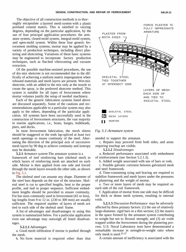
5.2.1 Armature system-The armature system is aframework of tied reinforcing bars (skeletal steel) towhich layers of reinforcing mesh are attached on eachside. Mortar is then applied from one side and forcedthrough the mesh layers towards the other side, as shownin Fig. 5.1.
FORCE PLASTER TOFULLY IMPREGNATE
PLASTER FROMARMATURE
1BOTH SIDES
J
SKELETAL STEELTIED TOGETHERAT INTERSECT IONS
LAYERS OF MESHEACH SIDE OFAND TIED TOSKELETAL STEEL
SKELETAL STEEL
m$$ :t; MESH LAYERS
[] MORTAR
Fig. 5.1-Armature system
The skeletal steel can assume any shape. Diameter ofthe steel bars depends on the size of the structure. Skel-etal steel is cut to specified lengths, bent to the properprofile, and tied in proper sequence. Sufficient embed-ment lengths should be provided to ensure continuity.For bar sizes commonly used in ferrocement (#2 or less),lap lengths from 9 to 12 in. (230 to 300 mm) are usuallysufficient. The required number of layers of mesh aretied to each side of the skeletal steel frame.
A list of advantages and disadvantages in using thissystem is summarized below. For a particular applicationeven one advantage may outweigh all listed disadvan-tages.
5.2.1.1 Advantagesa. Good mesh infiltration if mortar is pushed through
the mesh.b. No form material is required other than that
needed to support the armature.c. Repairs may proceed from both sides, and areas
requiring touchup are visible.5.2.1.2 Disadvantages
a. Reduced performance associated with embedmentof reinforcement (see Section 5.2.1.3).
b. Added weight associated with use of bars or rods.c. Possible galvanic corrosion between galvanized mesh
and steel framework.d. Time-consuming tying and bracing are required to
stabilize framework and mesh layers under the pressuresof plastering and the weight of mortar.
e. Two or more layers of mesh may be required oneach side of the rod framework.
f. Application of mortar from one side may be difficultfor thick or dense mesh systems, resulting in internalvoids.
5.2.1.3 Discussion-Performanceemay be adverselyaffected by three primary factors: (1) the use of relativelylarge-diameter, rigid bars in a thin section; (2) the matrixin the space formed by the armature system contributingto weight but not to flexural strength; and (3) air voidstrapped within the ferrocement during the plastering pro-cess. U.S. Naval Laboratory tests have demonstrated aremarkable increase in strength-to-weight ratio whereonly mesh is used.35-37
A certain amount of inefficiency is associated with the
549.1R-14 ACI COMMITTEE REPORT
armature system since a high percentage of the total steelused is located at or near the midsection of the bendingcross section. Thus, weight is added to the structure with-out significant increase in strength. Further, the overallthickness of ferrocement sections produced in the fullyplastered procedure is increased due to the use of arma-ture bars in the form of a grid and tied together. If toofew bars or rods are used and are not tied at a sufficientnumber of intersections, bulging may occur due to plas-tering pressures or simply the weight of the mortar.Often the weight of the framework and wet mortar cancause enough local and general distortion from the de-sired geometry that substantial shoring is required toprevent bulging. Bulging may result in thick, under-reinforced mesh sections that may later crack and spall.
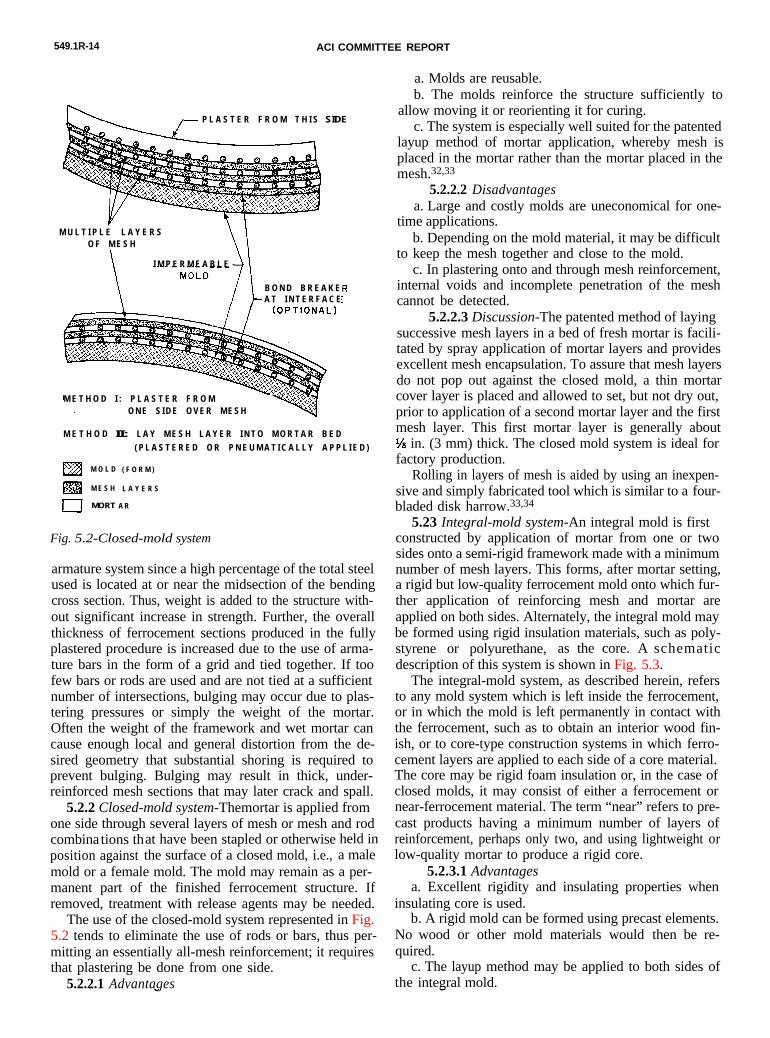
5.2.2 Closed-mold system-Themortar is applied fromone side through several layers of mesh or mesh and rodcombina tions that have been stapled or otherwise held inposition against the surface of a closed mold, i.e., a malemold or a female mold. The mold may remain as a per-manent part of the finished ferrocement structure. Ifremoved, treatment with release agents may be needed.
The use of the closed-mold system represented in Fig.5.2 tends to eliminate the use of rods or bars, thus per-mitting an essentially all-mesh reinforcement; it requiresthat plastering be done from one side.
P L A S T E R F R O M T H I S SIDE
M U L T I P L E L A Y E R SO F M E S H
I M P E R M E A B L E
B O N D B R E A K EA T I N T E R F A C E
M E T H O D I : P L A S T E R F R O MO N E S I D E O V E R M E S H
M E T H O D II: L A Y M E S H L A Y E R I N T O M O R T A R B E D
( P L A S T E R E D O R P N E U M A T I C A L L Y A P P L I E D )
M O L D
m‘qc_cs M E S H
I MORT
( F O R M )
L A Y E R S
A R
Fig. 5.2-Closed-mold system
5.2.2.1 Advantages
a. Molds are reusable.b. The molds reinforce the structure sufficiently to
allow moving it or reorienting it for curing.c. The system is especially well suited for the patented
layup method of mortar application, whereby mesh isplaced in the mortar rather than the mortar placed in themesh.32,33
5.2.2.2 Disadvantagesa. Large and costly molds are uneconomical for one-
time applications.b. Depending on the mold material, it may be difficult
to keep the mesh together and close to the mold.c. In plastering onto and through mesh reinforcement,
internal voids and incomplete penetration of the meshcannot be detected.
5.2.2.3 Discussion-The patented method of layingsuccessive mesh layers in a bed of fresh mortar is facili-tated by spray application of mortar layers and providesexcellent mesh encapsulation. To assure that mesh layersdo not pop out against the closed mold, a thin mortarcover layer is placed and allowed to set, but not dry out,prior to application of a second mortar layer and the firstmesh layer. This first mortar layer is generally aboutl/s in. (3 mm) thick. The closed mold system is ideal forfactory production.
Rolling in layers of mesh is aided by using an inexpen-sive and simply fabricated tool which is similar to a four-bladed disk harrow.33,34
5.23 Integral-mold system-An integral mold is firstconstructed by application of mortar from one or twosides onto a semi-rigid framework made with a minimumnumber of mesh layers. This forms, after mortar setting,a rigid but low-quality ferrocement mold onto which fur-ther application of reinforcing mesh and mortar areapplied on both sides. Alternately, the integral mold maybe formed using rigid insulation materials, such as poly-styrene or polyurethane, as the core. A schematicdescription of this system is shown in Fig. 5.3.
The integral-mold system, as described herein, refersto any mold system which is left inside the ferrocement,or in which the mold is left permanently in contact withthe ferrocement, such as to obtain an interior wood fin-ish, or to core-type construction systems in which ferro-cement layers are applied to each side of a core material.The core may be rigid foam insulation or, in the case ofclosed molds, it may consist of either a ferrocement ornear-ferrocement material. The term “near” refers to pre-cast products having a minimum number of layers ofreinforcement, perhaps only two, and using lightweight orlow-quality mortar to produce a rigid core.
5.2.3.1 Advantagesa. Excellent rigidity and insulating properties when
insulating core is used.b. A rigid mold can be formed using precast elements.
No wood or other mold materials would then be re-quired.
c. The layup method may be applied to both sides ofthe integral mold.
DESIGN, CONSTRUCTION, AND REPAIR OF FERROCEMENT 549.1R-15
T
PLASTER FROM EACH SIDE O RLAYUP F R O M E A C H SUEEMENT O RI S E ) T OI N S I D E
INTEGRAL MOLD
M E S H L A Y E R S
MORTAR
Fig 5.3-Integral-mold system
d. The layup method may be used against a closedmold, covered by the core materials, which are in turnlaid up with another ferrocement layer.
e. If rods must be used to form or reinforce the pre-cast core, their thickness can be filled with lightweightconcrete mortar.
f. The precast core generally requires much less tyingthan, for example, the armature system.
5.2.3.2 Disadvantagesa. May require special details for shear connection
between rigid ferrocement layers, especially across in-sulating cores.
5.2.3.3 Discussion-This method is ideal for fieldoperations. The possible variations are unlimited, pro-vided adequate attention is paid to structural detailingrequirements that assure the completed system will func-tion as a composite.
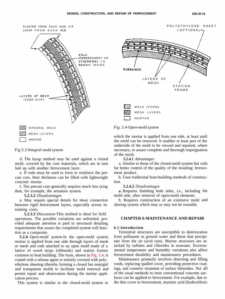
5.2.4 Open-mold system-In the open-mold system,mortar is applied from one side through layers of meshor mesh and rods attached to an open mold made of alattice of wood strips (ribbands) and station framescommon to boat building. The form, shown in Fig. 5.4, iscoated with a release agent or entirely covered with poly-ethylene sheeting (thereby forming a closed but nonrigidand transparent mold) to facilitate mold removal andpermit repair and observation during the mortar appli-cation process.
P O L Y E T H Y L E N E S H E E( O P T I O N A L )
7
L A Y E R S O FM E S H /
S T A T I O NF R A M E
M O L D ( F O R M )
lzll$y..&
,v_v” M E S H L A Y E R S
I M O R T A R
Fig. 5.4-Open-mold system
This system is similar to the closed-mold system in
which the mortar is applied from one side, at least untilthe mold can be removed. It enables at least part of theunderside of the mold to be viewed and repaired, wherenecessary, to assure complete and thorough impregnationof the mesh.
5.2.4.1 Advantagesa. Similar to those of the closed-mold system but with
far better control of the quality of the resulting ferroce-ment product.
b. Uses traditional boat-building methods of construc-tion.
5.2.4.2 Disadvantagesa. Requires finishing both sides, i.e., including
mold side, after removal of open-mold elements.b. Requires construction of an extensive mold
shoring system which may or may not be reusable.
CHAPTER 6-MAINTENANCE AND REPAIR
6.1-Introduction
the
and
Terrestrial structures are susceptible to deteriorationfrom pollutants in ground water and those that precipi-tate from the air (acid rain). Marine structures are at-tacked by sulfates and chlorides in seawater. Environ-mental temperature and humidity variations also affectferrocement durability and maintenance procedures.
Maintenance primarily involves detecting and fillingvoids, replacing spalled cover, providing protective coat-ings, and cosmetic treatment of surface blemishes. Not allof the usual methods to treat conventional concrete sur-faces can be applied to ferrocement. For example, due tothe thin cover in ferrocement, muriatic acid (hydrochloric
549.1R-16 ACI COMMITTEE REPORT
acid) should be used with extreme caution. Phosphoricacid and other nonchloride cleaners should be the speci-fied alternative (see Section 5.1.4).
Repairs seldom involve large quantities of materialsand are usually accomplished by hand. Emphasis shouldbe placed on ability of the repair material to penetratethe mesh cage, to fully coat the reinforcing to inhibit cor-rosion, and to bond to the substrate. Rapid set andstrength gain may be overriding considerations for emer-gency repairs. Protective coatings must bond well and bealkali tolerant, thermally compatible, and resistant toenvironmental pollutants and ultraviolet radiation, ifexposed.
Some useful information can be derived from litera-ture on bridge deck repair in the Guide for Repair ofConcrete Bridge Superstructures by ACI Committee 546.Terrestrial ferrocement structures are seldom exposed tothe severe conditions encountered by bridge decks, butthe recommendations and procedures reported by Tut-hill38 and other references listed in Reference on res-toration of deteriorated concrete provide a basis forunderstanding many repair methods that are applicableto ferrocement.
Available literature that details the methods for repairof ferrocement is generally nontechnical and written forrepair of boat hulls. The most complete repository ofinformation on ferrocement maintenance is located at theInternational Ferrocement Information Center (IFIC),Asian Institute of Technology, in Bangkok, Thailand.IFIC publishes the Journal of Ferrocement, which is de-voted to research and applications of ferrocement.
This chapter is intended to provide information on themost common generic compounds that are used in pro-prietary patching materials. Proprietary materials shouldbe reviewed before using them to patch ferrocement.Many materials have been tested by government agen-cies, and over 300 are listed in the “Patching Materials”section of SPEL, Special Product Evaluation List.39
6.2-Blemish and stain removal6.2.1 General-Because ferrocement is usually less
porous than conventional concrete, stains do not pene-trate very deeply in the mortar matrix. The thin cover ofmortar over ferrocement reinforcement also means thatgreater care must be taken when preparing the surface.
Reference 40 discusses stain removal for concrete.Bulletins on the subject41,422 are based on the results of acooperative investigation by the U.S. Bureau of Stan-dards and the National Association of Marble Dealers.
All sources agree that even weak acids, such as oxalic,carbonic, and acetic, may etch concrete if they are leftfor extended lengths of time and not neutralized or com-pletely flushed off.
6.2.2 Construction blemishes-Construction blemishesare often caused by improper selection or use of mater-ials, faulty workmanship, uneven evaporation, and unevencuring. Other causes include:
1. Cement from different mills will cause color varia-
tion, although most of the color in mortar is due to thesand component. Where appearance is critical, careshould be taken to obtain sand from a single source andhave it thoroughly washed.
2. Mottling results from the use of calcium chloride orhigh-alkali cement combined with uneven curing.
3. The use of polyethylene sheet material to cover sur-faces promotes uneven curing.
4. The water-cement ratio affects tone and surface ap-pearance. Low water-cement ratios will result in a darkerappearance.
5. Hard steel troweling densifies the surface, causingmore rapid drying and also leaving a darkened surface.
6.2.3 Stain removal-Treatment of stains should bedone promptly after the discoloration appears. Thoroughflushing and brushing with a stiff bristle brush anddetergent is the first approach. If this is ineffective, adilute (about three percent) solution of phosphoric oracetic acid can be applied. Another chemical treatmentconsidered safe and effective is a 20 to 30 solution ofdiammonium citrate, a mild acid which attacks calciumcarbonates and calcium hydroxide. This treatment makesthe surface more porous and promotes hydration.
When a stain has penetrated too deeply to be re-moved by surface chemical application and scrubbing, apoultice or a bandage may be needed. A poultice isintended to dissolve the stain and absorb it into thepoultice. The poultice is made by mixing one or morechemicals such as a solution of phosphoric acid with afine inert powder such as talc, whiting, hydrated lime, ordiatomaceous earth to form a paste. The paste is spreadin a thick layer over the stain and allowed to dry. Abandage may consist of a few layers of cloth or papertoweling soaked in a chemical solution. More than oneapplication of a poultice or bandage may be needed forstubborn stains.
Caution: Most of the chemicals used to remove stainsare toxic and require safeguards against skin contact andinhalation. Whenever acids are used, surfaces should firstbe saturated with water or the dissolved stain materialmay migrate deeper into the concrete and reappear at alater date as efflorescence.
6.2.4 Efflorescence-When water-bearing salts migrateto exposed surfaces of concrete, evaporation will result inthe deposit of salts on the surface. This process is termedefflorescence. It occurs most readily in porous concreteso it should not be a problem for ferrocement made witha water-cement ratio of not more than 0.4 and is wellcompacted to be free of voids. Voids, if present, may fillwith water (in certain applications) and efflorescence willappear on surfaces around the place where water gainedentrance to the void.
Treatment consists of breaking into the void, as witha hammer, and replastering, or drilling into the void witha masonry bit and injecting a nonshrinking cement grout.
6.3-Protective surface treatments6.3.1 General-Good-quality mortar has excellent re-
DESIGN, CONSTRUCTION, AND REPAIR OF FERROCEMENT 549.1R-17
sistance to weathering. General construction usually doesnot require any protective surface treatment. However,the application of protective surface treatments can im-prove the performance of ferrocement and extend itsuseful service life. Surface treatments can be used toimprove appearance, harden the surface, and reduce per-meability, thus guarding against the corrosive action ofacids, alkaline salts, and organic substances.
Appendix D of this report, and ACI Committee 515’sreport, A Guide to the Use of Waterproofing, Dampproof-ing, Protective, and Decorative Barrier Systems for Concrete,provide an extensive list of substances that may come incontact with ferrocement and recommend preventivemeasures for those which may be deleterious.
6.3.2 Hardeners-The most commonly available hard-ener often recommended is sodium silicate, also calledwater glass. It is quite viscous and must be diluted withwater to achieve penetration. The amount of dilutiondepends on the quality of the silicate and the permea-bility of the concrete. Silicate of about 42.5 degreeBaume gravity diluted in the proportion of 1 gal. (3.78 1)of silicate with 4 gal. (15.12 1) of water usually makes agood solution for the first application. A strongersolution can be used for succeeding coats. Each coatmust be completely dry before the next coat is applied.
Other hardeners which seal and prepare the surfacefor application of oil-base paints are magnesium fluo-silicate and zinc fluosilicate.43 The treatment consists oftwo or more applications. A solution containing about 1lb. (0.45 kg) of fluosilicate crystals per gal. of watershould be used for the first application; and a solutioncontaining 2 lb/gal. (0.24 kg/l) should be used for sub-sequent applications. After the last application has dried,the surface should be brushed and washed with water toremove any crystals that may have formed.
6.3.3 Coatings-Epoxy and polyurethane compoundsare the most widely mentioned protective coatings forconcrete. They have excellent adhesion to ferrocementmortar and are alkali resistant. Some compounds degradeunder exposure to ultraviolet (UV) rays, become brittlewith age, and have a much higher coefficient of expan-sion than concrete. They have not performed well on sur-faces exposed to sunlight or subjected to wide thermalvariation. A thick epoxy coating is stronger than thecement substrate and very likely will shear below thebondline of surfaces exposed to wide temperaturechanges such as boat decks. As the sealing and bondcharacteristics of epoxies are desirable, a satisfactorydeck finish can consist of one or two thin coats of epoxy,followed by one or more coats of polyurethane contain-ing a UV inhibitor.
Polyurethanes, especially those furnished in two-partmixtures, are considered to offer the best resistance toabrasion among the commonly available coatings, whilethose formulated from acrylics provide the best resistanceto sunlight and weathering. An example can be found inReference 44. Acrylic latex house paints are widely usedon ferrocement and have the advantage of being water-
based so they can be applied to damp surfaces.For any surface opposite a surface sealed with an
impermeable coating, an acrylic coating (or silicone andsilane coating) formulated to allow the escape of watervapor should be specified.
6.3.4 Sheathing-Fiberglass laminates often have beenused on boat hulls to seal the surface against leakage andimprove impact resistance; however, the polyester resinsused in the fiberglass boat building industry have pooradhesion to ferrocement, so epoxy resins are preferred.
Not all applications of epoxy-based fiberglass lamin-ates have been successful.45 Several factors, such as am-bient temperature during sheathing, soiled mortar sur-face, or thermal incompatibility of the materials, maycontribute to failure of the sheathing.
6.4-Damage repair6.4.1 General-Repairs have received little attention in
ferrocement literature beyond instructions to removeloose mortar, push the armature back into shape, and re-plaster.
Hagenbach45 reports on several cases and tells how re-pairs were made, including one repair made under water.Donovan and Baugh46 cover several case studies on thegrouting and repair of ferrocement hulls. Bowen47
reports on the reconstruction of a boat thought to bebeyond repair. Watkins484describes extensive damage andrepair to a 53 ft (16.15 m) fishing vessel.
Biggs49 points out that damage must be repairedquickly because, while ferrocement has good resistanceto a single impact, repeated impacts at load levels wellbelow the initial impact will pulverize the mortar. Asimilar danger exists when major cracks are allowed toexpand under cyclic loading.
6.4.2 Common types of damage6.4.2.1 Delaminations-Delaminations occur when
ferrocement splits between layers which may be in lam-inated construction. This may be due to springing back orbridging of the mesh during construction. Delaminationsometimes occurs at or near the neutral axis under im-pact or flexure when there are many voids in the interiorlayers. Such areas give off a hollow sound when tappedwith a hammer or stroked with a steel bar.
Pressure from expansive corrosion products may alsocause delamination. The Guide for Repair of ConcreteBridge Superstructures, by ACI Committee 546 recom-mends tests to determine whether corrosion of the rein-forcement is active, but as a practical matter, mostferrocement can be opened up for visual inspection.
6.4.2.2 Spalls-A spall is defined in ACI 116R as adepression resulting when a fragment is detached from alarger mass by a blow, by the action of weather, by pres-sure, or by expansion within the mass. Spalls are referredto as large when their size exceeds approximately % in.(19 mm) in depth or 6 in. (152 mm) in any dimension.
Spalls are usually caused by corrosion of steel, whichcauses an expansive pressure within the ferrocement.Chlorides in the concrete greatly increase the potential
549.1R-18 ACI COMMITTEE REPORT
l Benford, J., personal communication to M.E. Iorns about a fire at the Peter-son Boatyard, Tacoma, Washington.
for corrosion of the steel. Under such conditions, con-tinued spalling is likely and the repair of local spalI areasmay even promote the deterioration of the concrete be-cause of the presence of dissimilar materials.
An area of steel corrosion and chloride-contaminatedconcrete may be considerably larger than the area ofspalled concrete, and if only the spall area is repaired, acontinuing repair program will probably be required.
6.4.2.3 Scaling-Scaling is defined as local flaking orpeeling away of material near the surface of the mortar.It is caused by the generation of internal pressures duringfreezing of water trapped in saturated voids.
6.4.2.4 Fire damage-No definitive study of fire re-sistance has yet been published, although some work hasbeen done under the direction of Williamson.50 It hasbeen hypothesized that ferrocement might be more sus-ceptible to fire damage than conventional concretebecause of the thin cover, but preliminary findingsindicate otherwise.
It is possible that the mortar protects the ferrocementreinforcing, which in turn distributes and dissipates theheat evenly with little damage to the composite. Alsocontributing to fire resistance may be the fact that thetypical ferrocement mortar is relatively nonporous andcontains little water to generate steam pressure onheating. The absence of large aggregate having varyingthermal characteristics may also contribute to increasingfire resistance.
If the fire were intense enough to release the amountof chemically bound water in the cement, destroy thebond between the cement and the aggregate, or oxidizethe reinforcement, the surface would be charred andspalled so that the damage could be easily identified.Full-scale removal and repair is then required. Benford*and Iorns51 have reported instances where ferrocementboats survived fires which would have destroyed steelboats.
6.4.2.5 Cracks and local fractures-Hairline cracksand crazing due to temperature changes or drying shrink-age in the cover coat do not require repair. Continuouswet curing will cause autogenous healing, and a flexiblecoating will conceal the crack from view. If cracks arecaused by continuing overloads or are due to structuralsettlement and the cause cannot be removed, replace-ment or a structural overlay will be required. Cracks dueto occasional impact or overload are repairable.
Local fractures are cracks in which displacement ofthe section has occurred as a result of impact.
6.4.3 Evaluation and testing-Evaluation of damagemust take into consideration its extent, cause, andlikelihood of the cause still being active. The method ofrepair will be dictated by the type of damage, theavailability of special equipment and repair materials,and the level of skill of the workers employed.
Economic factors may influence the decision as towhether the repair should be extensive and permanent,or limited in scope in response to an immediate problem.A leak in a tank or boat hull may be stopped with a sur-
face sealant, but the presence of the leak indicates thatthe interior reinforcement has been exposed to moisture,oxygen, and possibly other corrosive agents. It may alsoindicate poor workmanship during fabrication, and thestrong possibility that other voids are present that needto be located and repaired.
Repair materials should bond to the original structure;resist pollutants in the surrounding soil, water or air; andrespond in the same way to changes in temperature,moisture, and loads. Removal of deteriorated or chlor-ide-contaminated mortar trapped within the reinforcingmesh requires a large amount of hand labor, so it may beeconomical (and better for long-term durability) to re-construct or replace an entire area using the originalstructure as a form which can be left in place or removedafter the overlaid structure has cured. Complete recon-struction is advisable when chloride contamination, meshcorrosion, and deterioration of the mortar are extensive.
Testing ferrocement is usually done by tapping with ahammer to break into any voids under the surface, or bydrawing a metal bar over the surface and listening forsounds indicating voids or the presence of deterioratedconcrete. A high-quality ferrocement should produce abell-like sound and resist moderately severe hammerblows without damage.
6.4.4 Surface preparation6.4.4.1 General-The primary objective is to remove
any deteriorated mortar or mortar contaminated withcorrosive agents and to provide a surface to which therepair materials can be bonded properly. The rougher thesurface, the greater the area available for bonding.
6.4.4.2 Removal of deteriorated concrete-The firststep in any repair is to remove all disintegrated, unsound,and contaminated mortar. Saws and chipping hammersused for conventional concrete are unsuitable for fer-rocement unless large sections are to be completelyremoved.
Small areas are quickly prepared by hand hammeringjust hard enough to pulverize deteriorated or crackedmortar, but not to the point of damaging the reinforcingmesh.
Scott and Greenius52 found that a pneumatic needlegun is very effective for cleaning out broken ferrocement,opening out cracks, and roughening the surface. Thisdevice is similar to airpowered chipping and scaling tools,but uses a bundle of small-diameter steel rods.
Particles of sound mortar embedded in the mesh neednot be removed if they are small enough not to interferewith the penetration of new mortar or project from thefinished surface.
6.4.4.3 Reinforcement-Any loose, scaly corrosionrevealed on cleaning out the mortar must be removed bysandblasting, water jet, airblasting, or vacuum methods.
An alternate method for removing rust is to brushnaval jelly or spray dilute phosphoric acid over the repair
DESIGN, CONSTRUCTION, AND REPAIR OF FERROCEMENT 549.1R-19
area and flush thoroughly.Where the mesh cage has been displaced but is still in-
tact, it is pushed or jacked back in place and supportedsecurely to withstand the pressure of applying the repairmaterial. Where the reinforcing has been torn, the oldmesh may need to be laced back to close the opening.
The rods supporting the mesh cage are often badlydistorted by impact but seldom sheared off. If rods mustbe spliced, a 15-diameter overlap of the partner rod isusually sufficient; otherwise hooks can be used.
6.4.4.4 Cleaning-Loose particles and dust residuefrom hammering or sandblasting should be air jetted orvacuum cleaned if epoxy or methymethacrylate (MMA)is the repair material. Water jetting is an option if therepair is to be made with hydraulic cement or latexmodified mortar.
If an air jet is used, the compressor should beequipped with an oil trap to prevent contamination ofthe surface. Surface oil or dirt can be removed bytrisodium phosphate or other strong detergents.
6.4.4.5 Cracks-Cleaning cracks presents a specialproblem since ferrocement is seldom used for horizontalflat surfaces which can be filled by gravity flow. It isusually simpler to hammer out the mortar on each sideof the crack and replaster with latex mortar.
If opening the crack is not feasible, epoxy or MMAinjection systems may be attempted in accordance withthe product directions. Generally the crack is firstcleaned with oil-free compressed air, and small [about l/sin. (2 to 3 mm)] drill holes are made at the highest andlowest points in the crack. The surface between the holesis sealed with strong coatings or a pressure pad. Cata-lyzed epoxy or MMA is injected at the lower hole untilit comes out at the upper hole.
If a latex-cement grout is to be used, the interior ofthe crack must be thoroughly saturated with water andallowed to drain.
6.5-Repair materials6.5.1 Portland cement-Portland cement (see ACI
225R) is usually the most readily available and least ex-pensive repair material. Its characteristics are well knownand compatible with the ferrocement in terms of thermaland moisture variations. Some recommendations on ce-ment selection can be found in Section 3.1.1 of thisguide.
Sand matching that used in the original constructionis suitable unless the need for the repair arose because ofreactive or contaminated sand.
Neat portland or blended cement paste is used to fillsmall cracks, and a mortar with fine sand is used to filllarger cracks or voids. Both are used in combination withlatex for thin patches and overlays. The chief disadvan-tage of paste is that it shrinks as it dries. Shrinkagedisturbs the bond and necessitates repeated applicationsto achieve the original level. Otherwise, the patch mustbe overfilled and ground down.
The higher the sand content and the lower the watercontent of mortar, the less shrinkage. Larger cracksshould be coated with a neat cement slurry, then dry-packed with a very low water-cement ratio mortar.
Of the synthetic latexes which have been promoted foruse in portland cement mortars, polyvinyl acetate andpolyvinylidene are unsuitable for wet environments.
The leading latexes are now styrene-butadiene, whichis widely used in bridge deck overlays and for which U.S.standards have been established,1 and acrylics, whichoffer better protection from ultraviolet degradation andhave been successfully used for over 15 years in the pro-duction and repair of ferrocement boats and pontoons.Acrylics can be used as admixtures to improve bondingand as curing compounds.
The addition of latex to portland cement mortarmarkedly improves bond to the substrate and the tensilestrength of the patch. Further, the resin deposited as thewater is removed from the latex emulsion fills the poresand blocks subsequent penetration of corrosive agents.The latex forms a skin over the surface through evapor-ation and keeps the interior water available for hydrationof the cement. The patch or overlay thus becomes self-curing.
Acrylic latex in concentrated form contains slightly lessthan 50 percent solids. It is usually diluted to a range ofbetween 10 and 20 percent solids and is then used as themixing water for the mortar. Latex mortars can be ap-plied to a damp surface, but the patch must be allowedto dry thoroughly before being immersed in water.
6.5.2 Polymer mortars-Nonlatex polymer mortars re-quire the use of surface-dried and, preferably, oven-driedsand. The monomers have very low viscosity and so mustbe mixed with thickening agents to be placed in any areawhich cannot be sealed tightly. There are prepackagedproprietary MMA systems available that can be handledlike conventional mortar. Epoxy resins are available innumerous formulations varying in viscosity and tempera-ture requirements. Some are moisture tolerant and canbe made to bond to damp surfaces.
Many polymers or the promoters and hardeners usedwith them are toxic, so great care must be used in theirapplication.
6.5.3 Admixtures-Time is a critical element in manyrepairs, so accelerators are frequently employed wherecement alone is the repair material. Because chloridecompounds may promote corrosion, nonchloride acceler-ators are preferred for all ferrocement but particularlyfor ferrocement in marine service. Despite this, emer-gency repairs of small areas are often made below thewaterline with neat cement moistened to a putty con-sistency with a concentrated solution of calcium chloride.This mixture soon becomes noticeably warm, so is re-ferred to as a “hot plug.” It is carried in the hand or in aplastic bag to the site of the leak, pressed into the hole,and held a few minutes until set. Permanent repairshould be accomplished as soon as possible, using mater-ials without chlorides.
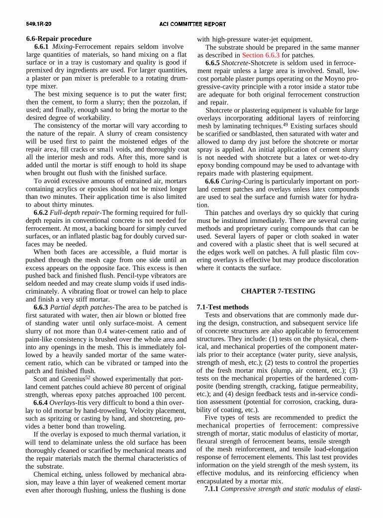
6.6-Repair procedure6.6.1 Mixing-Ferrocement repairs seldom involve
large quantities of materials, so hand mixing on a flatsurface or in a tray is customary and quality is good ifpremixed dry ingredients are used. For larger quantities,a plaster or pan mixer is preferable to a rotating drum-type mixer.
The best mixing sequence is to put the water first;then the cement, to form a slurry; then the pozzolan, ifused; and finally, enough sand to bring the mortar to thedesired degree of workability.
The consistency of the mortar will vary according tothe nature of the repair. A slurry of cream consistencywill be used first to paint the moistened edges of therepair area, fill cracks or small voids, and thoroughly coatall the interior mesh and rods. After this, more sand isadded until the mortar is stiff enough to hold its shapewhen brought out flush with the finished surface.
To avoid excessive amounts of entrained air, mortarscontaining acrylics or epoxies should not be mixed longerthan two minutes. Their application time is also limitedto about thirty minutes.
6.6.2 Full-depth repair-The forming required for full-depth repairs in conventional concrete is not needed forferrocement. At most, a backing board for simply curvedsurfaces, or an inflated plastic bag for doubly curved sur-faces may be needed.
When both faces are accessible, a fluid mortar ispushed through the mesh cage from one side until anexcess appears on the opposite face. This excess is thenpushed back and finished flush. Pencil-type vibrators areseldom needed and may create slump voids if used indis-criminately. A vibrating float or trowel can help to placeand finish a very stiff mortar.
6.6.3 Partial depth patches-The area to be patched isfirst saturated with water, then air blown or blotted freeof standing water until only surface-moist. A cementslurry of not more than 0.4 water-cement ratio and ofpaint-like consistency is brushed over the whole area andinto any openings in the mesh. This is immediately fol-lowed by a heavily sanded mortar of the same water-cement ratio, which can be vibrated or tamped into thepatch and finished flush.
Scott and Greenius52 showed experimentally that port-land cement patches could achieve 80 percent of originalstrength, whereas epoxy patches approached 100 percent.
6.6.4 Overlays-Itis very difficult to bond a thin over-lay to old mortar by hand-troweling. Velocity placement,such as spritzing or casting by hand, and shotcreting, pro-vides a better bond than troweling.
If the overlay is exposed to much thermal variation, itwill tend to delaminate unless the old surface has beenthoroughly cleaned or scarified by mechanical means andthe repair materials match the thermal characteristics ofthe substrate.
Chemical etching, unless followed by mechanical abra-sion, may leave a thin layer of weakened cement mortareven after thorough flushing, unless the flushing is done
with high-pressure water-jet equipment.The substrate should be prepared in the same manner
as described in Section 6.6.3 for patches.6.6.5 Shotcrete-Shotcrete is seldom used in ferroce-
ment repair unless a large area is involved. Small, low-cost portable plaster pumps operating on the Moyno pro-gressive-cavity principle with a rotor inside a stator tubeare adequate for both original ferrocement constructionand repair.
Shotcrete or plastering equipment is valuable for largeoverlays incorporating additional layers of reinforcingmesh by laminating techniques.49 Existing surfaces shouldbe scarified or sandblasted, then saturated with water andallowed to damp dry just before the shotcrete or mortarspray is applied. An initial application of cement slurryis not needed with shotcrete but a latex or wet-to-dryepoxy bonding compound may be used to advantage withrepairs made with plastering equipment.
6.6.6 Curing-Curing is particularly important on port-land cement patches and overlays unless latex compoundsare used to seal the surface and furnish water for hydra-tion.
Thin patches and overlays dry so quickly that curingmust be instituted immediately. There are several curingmethods and proprietary curing compounds that can beused. Several layers of paper or cloth soaked in waterand covered with a plastic sheet that is well secured atthe edges work well on patches. A full plastic film cov-ering overlays is effective but may produce discolorationwhere it contacts the surface.
CHAPTER 7-TESTING
7.1-Test methodsTests and observations that are commonly made dur-
ing the design, construction, and subsequent service lifeof concrete structures are also applicable to ferrocementstructures. They include: (1) tests on the physical, chem-ical, and mechanical properties of the component mater-ials prior to their acceptance (water purity, sieve analysis,strength of mesh, etc.); (2) tests to control the propertiesof the fresh mortar mix (slump, air content, etc.); (3)tests on the mechanical properties of the hardened com-posite (bending strength, cracking, fatigue permeability,etc.); and (4) design feedback tests and in-service condi-tion assessment (potential for corrosion, cracking, dura-bility of coating, etc.).
Five types of tests are recommended to predict themechanical properties of ferrocement: compressivestrength of mortar, static modulus of elasticity of mortar,flexural strength of ferrocement beams, tensile strengthof the mesh reinforcement, and tensile load-elongationresponse of ferrocement elements. This last test providesinformation on the yield strength of the mesh system, itseffective modulus, and its reinforcing efficiency whenencapsulated by a mortar mix.
7.1.1 Compressive strength and static modulus of elasti-
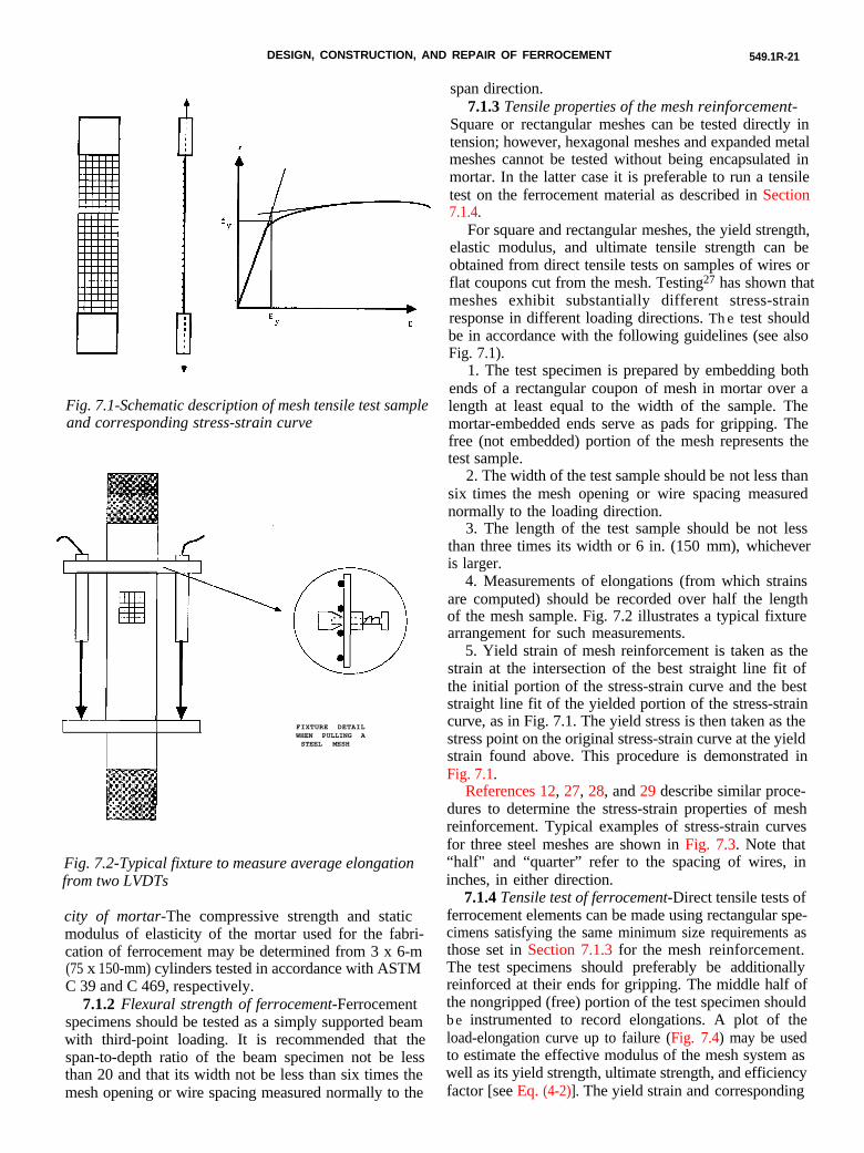
DESIGN, CONSTRUCTION, AND REPAIR OF FERROCEMENT 549.1R-21
city of mortar-The compressive strength and staticmodulus of elasticity of the mortar used for the fabri-cation of ferrocement may be determined from 3 x 6-m(75 x 150-mm) cylinders tested in accordance with ASTMC 39 and C 469, respectively.
7.1.2 Flexural strength of ferrocement-Ferrocementspecimens should be tested as a simply supported beamwith third-point loading. It is recommended that thespan-to-depth ratio of the beam specimen not be lessthan 20 and that its width not be less than six times themesh opening or wire spacing measured normally to the
span direction.7.1.3 Tensile properties of the mesh reinforcement-
Square or rectangular meshes can be tested directly intension; however, hexagonal meshes and expanded metalmeshes cannot be tested without being encapsulated inmortar. In the latter case it is preferable to run a tensiletest on the ferrocement material as described in Section7.1.4.
For square and rectangular meshes, the yield strength,elastic modulus, and ultimate tensile strength can beobtained from direct tensile tests on samples of wires orflat coupons cut from the mesh. Testing27 has shown thatmeshes exhibit substantially different stress-strainresponse in different loading directions. The test shouldbe in accordance with the following guidelines (see alsoFig. 7.1).
IIIIII)IIIIII
Fig. 7.1-Schematic description of mesh tensile test sampleand corresponding stress-strain curve
1. The test specimen is prepared by embedding bothends of a rectangular coupon of mesh in mortar over alength at least equal to the width of the sample. Themortar-embedded ends serve as pads for gripping. Thefree (not embedded) portion of the mesh represents thetest sample.
2. The width of the test sample should be not less thansix times the mesh opening or wire spacing measurednormally to the loading direction.
3. The length of the test sample should be not lessthan three times its width or 6 in. (150 mm), whicheveris larger.
4. Measurements of elongations (from which strainsare computed) should be recorded over half the lengthof the mesh sample. Fig. 7.2 illustrates a typical fixturearrangement for such measurements.
FIXTURE DETAILWHEN PULLING ASTEEL MESH
Fig. 7.2-Typical fixture to measure average elongationfrom two LVDTs
5. Yield strain of mesh reinforcement is taken as thestrain at the intersection of the best straight line fit ofthe initial portion of the stress-strain curve and the beststraight line fit of the yielded portion of the stress-straincurve, as in Fig. 7.1. The yield stress is then taken as thestress point on the original stress-strain curve at the yieldstrain found above. This procedure is demonstrated inFig. 7.1.
References 12, 27, 28, and 29 describe similar proce-dures to determine the stress-strain properties of meshreinforcement. Typical examples of stress-strain curvesfor three steel meshes are shown in Fig. 7.3. Note that“half" and “quarter” refer to the spacing of wires, ininches, in either direction.
7.1.4 Tensile test of ferrocement-Direct tensile tests offerrocement elements can be made using rectangular spe-cimens satisfying the same minimum size requirements asthose set in Section 7.1.3 for the mesh reinforcement.The test specimens should preferably be additionallyreinforced at their ends for gripping. The middle half ofthe nongripped (free) portion of the test specimen shouldbe instrumented to record elongations. A plot of theload-elongation curve up to failure (Fig. 7.4) may be usedto estimate the effective modulus of the mesh system aswell as its yield strength, ultimate strength, and efficiencyfactor [see Eq. (4-2)]. The yield strain and corresponding
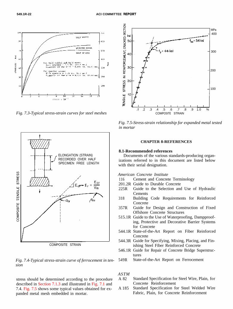
549.1R-22 ACI COMMITTEE
STRAIN x 1O-3
Fig. 7.3-Typical stress-strain curves for steel meshes
stress should be determined according to the proceduredescribed in Section 7.1.3 and illustrated in Fig. 7.1 and7.4. Fig. 7.5 shows some typical values obtained for ex-panded metal mesh embedded in mortar.
w
R
tw-- _--_ - -
J
1 t1
ELONGATION (STRAIN)RECORDED OVER HALFSPECIMEN FREE LENGTH
_ _ - - - _-
///
Lf E’
crEc7E, = -
/ Vfl
COMPOSITE STRAIN
Fig. 7.4-Typical stress-strain curve of ferrocement in ten-sion
MPa- 400
300
200
100
I I I I I I 1 I 1
.2 .3 .4 .5 .6 .7 .8 .9 1.0 %COMPOSITE STRAIN
Fig. 7.5-Stress-strain relationship for expanded metal testedin mortar
CHAPTER 8-REFERENCES
8.1-Recommended referencesDocuments of the various standards-producing organ-
izations referred to in this document are listed belowwith their serial designation.
Cement and Concrete TerminologyGuide to Durable ConcreteGuide to the Selection and Use of HydraulicCements
American Concrete Institute116201.2R225R
318
357R
515.1R
Building Code Requirements for ReinforcedConcreteGuide for Design and Construction of FixedOffshore Concrete StructuresGuide to the Use of Waterproofing, Dampproof-ing, Protective and Decorative Barrier Systemsfor Concrete
544.1R
544.3R
546.1R
549R
ASTMA 82
A 185
State-of-the-Art Report on Fiber ReinforcedConcreteGuide for Specifying, Mixing, Placing, and Fin-ishing Steel Fiber Reinforced ConcreteGuide for Repair of Concrete Bridge Superstruc-turesState-of-the-Art Report on Ferrocement
Standard Specification for Steel Wire, Plain, forConcrete ReinforcementStandard Specification for Steel Welded WireFabric, Plain, for Concrete Reinforcement
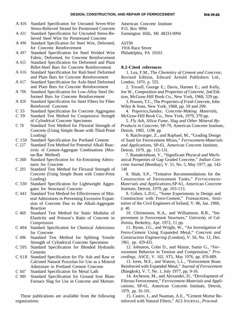
DESIGN, CONSTRUCTION, AND REPAIR OF FERROCEMENT
A 416
A 421
A 496
A 497
A 615
A 616
A 617
A 706
A 820
C 33C 39
C 78
C 150C 227
C 260
C 293
C 330
C 441
C 469
C 494
C 496
C 595
C 618
C 847C 989
Standard Specification for Uncoated Seven-Wire Stress-Relieved Strand for Prestressed Concrete Standard Specification for Uncoated Stress-Re- lieved Steel Wire for Prestressed ConcreteStandard Specification for Steel Wire, Deformed, for Concrete Reinforcement Standard Specification for Steel Welded Wire Fabric, Deformed, for Concrete ReinforcementStandard Specification for Deformed and PlainBillet-Steel Bars for Concrete ReinforcementStandard Specification for Rail-Steel Deformedand Plain Bars for Concrete ReinforcementStandard Specification for Axle-Steel Deformedand Plain Bars for Concrete ReinforcementStandard Specification for Low-Alloy Steel De-formed Bars for Concrete ReinforcementStandard Specification for Steel Fibers for FiberReinforced ConcreteStandard Specification for Concrete AggregatesStandard Test Method for Compressive Strengthof Cylindrical Concrete SpecimensStandard Test Method for Flexural Strength ofConcrete (Using Simple Beam with Third-PointLoading)Standard Specification for Portland CementStandard Test Method for Potential Alkali Reac-tivity of Cement-Aggregate Combinations (Mor-tar-Bar Method)Standard Specification for Air-Entraining Admix-tures for ConcreteStandard Test Method for Flexural Strength ofConcrete (Using Simple Beam with Center-PointLoading)Standard Specification for Lightweight Aggre-gates for Structural ConcreteStandard Test Method for Effectiveness of Min-eral Admixtures in Preventing Excessive Expan-sion of Concrete Due to the Alkali-AggregateReactionStandard Test Method for Static Modulus ofElasticity and Poisson’s Ratio of Concrete inCompressionStandard Specification for Chemical Admixturesfor ConcreteStandard Test Method for Splitting TensileStrength of Cylindrical Concrete SpecimensStandard Specification for Blended HydraulicCementsStandard Specification for Fly Ash and Raw orCalcined Natural Pozzolan for Use as a MineralAdmixture in Portland Cement ConcreteStandard Specification for Metal LathStandard Specification for Ground Iron Blast-Furnace Slag for Use in Concrete and Mortars
These publications are available from the following organizations:
American Concrete InstituteP.O. Box 9094Farmington Hills, MI 48333-9094
ASTM1916 Race StreetPhiladelphia, PA 19103
8.2-Cited references1. Lea, F.M., The Chemistry of Cement and Concrete,
Revised Edition, Edward Arnold Publishers Ltd.,London, 1970, p. 555.
2. Troxell, George E.; Davis, Harmer E.; and Kelly,Joe W., Composition and Properties of Concrete, 2nd Edi-tion, McGraw-Hill Book Co., New York, 1968, 529 pp.
3. Powers, T.C., The Properties of Fresh Concrete, JohnWiley & Sons, New York, 1968, pp. 59 and 299.
4. Popovics,Sandor, Concrete-Making Materials,McGraw-Hill Book Co., New York, 1979, 370 pp.
5. Fly Ash, Silica Fume, Slag and Other Mineral By-Products in Concrete, SP-79, American Concrete Institute,Detroit, 1983, 1196 pp.
6. Raichvarger, Z., and Raphael, M., “Grading Designof Sand for Ferrocement Mixes,” Ferrocement-Materialsand Applications, SP-61, American Concrete Institute,Detroit, 1979, pp. 115-131.
7. Ramakrishnan, V., “Significant Physical and Mech-anical Properties of Gap Graded Concrete,” Indian Con-crete Journal (Bombay), V. 51, No. 5, May 1977, pp. 142-148
8. Shah, S.P., “Tentative Recommendations for theConstruction of Ferrocement Tanks,” Ferrocement-Materials and Applications,SP-61, American ConcreteInstitute, Detroit, 1979, pp. 103-113.
9. Cohen, L.D.G., “Some Experiments in Design andConstruction with Ferro-Cement,” Transactions, Insti-tution of the Civil Engineers of Ireland, V. 86, Jan. 1960,p. 40.
10. Christensen, K.A., and Williamson, R.B., “Im-provement in Ferrocement Structures,” University of Cal-ifornia, Berkeley, Apr. 1972, 11 pp.
11. Byrne, J.G., and Wright, W., “An Investigation ofFerro-Cement Using Expanded Metal,” Concrete andConstruction Engineering (London), V. 56, No. 12, Dec.1961, pp. 429-433.
12. Johnston, Cohn D., and Mattar, Samir G., “Fer-rocement Behavior in Tension and Compression,” Pro-ceedings, ASCE, V. 102, ST5, May 1976, pp. 876-889.
13. Iorns, M.E., and Watson, L.L., “Ferrocement BoatsReinforced with Expanded Metal,” Journal of Ferrocement(Bangkok), V. 7, No. 1, July 1977, pp. 9-16.
14. Atcheson, M., and Alexander, D., “Development ofFibrous Ferrocement,” Ferrocement-Materials and Appli-cations, SP-61, American Concrete Institute, Detroit,1979, pp. 81-101. _
15. Castro, J., and Naaman, A.E., “Cement Mortar Re-inforced with Natural Fibers,” ACI JOURNAL, Proceed-
549.1R-24 ACI COMMITTEE REPORT
ings, V. 78, No. 1, Jan.-Feb., 1981, pp. 69-78. 16. Pakotiprapha, B.; Pama, R.P.; and Lee, S.L.,
“Analysis of a Bamboo Fiber-Cement Paste Composite,”Journal of Ferrocement (Bangkok), V. 13, No. 2, Apr.1983, pp. 141-159.
17. Balaguru, P., and Shah, S., “Alternative Rein- forcing Materials for Less Developed Countries,” Inter- national Journal of Development Technology, V. 3, 1985,pp. 87-105.
18. Ali, Z., and Pama, R.P., “Mechanical Properties of Bamboo Reinforced Slabs,” Proceedings, International Conference on Materials of Construction for Developing Countries, Asian Institute of Technology, Bangkok, 1978, pp. 49-66.
19. Nillson, L., “Reinforcement of Concrete with Sisal and Other Vegetable Fibers,” Document No. D-14, Swe- dish Council for Building Research, Stockholm, 1975, 68 pp .
20. Naaman, A.E., and Homrich, J.R., “Flexural De- sign of Ferrocement: Computerized Evaluation and De- sign Aids,” Journal of Ferrocement (Bangkok), V. 16, No. 2, Apr. 1986, pp. 101-116.
21. Balaguru, Perumalsamy N.; Naaman, Antoine E.; and Shah, Surendra P., “Analysis and Behavior of Fer- rocement in Flexure,” Proceedings, ASCE, V. 103, ST10, Oct. 1977, pp. 1937-1951.
22. Johnston, Colin D. and Mowat, Dallas N., “Ferro- cement-Material Behavior in Flexure,” Proceedings, ASCE, V. 100, No. ST10, Oct. 1974, pp. 2053-2069.
23. Balaguru, Perumalsamy N.; Naaman, Antoine E.; and Shah, Surendra P., “Ferrocement in Bending; Part I: Static Nonlinear Analysis,” Report No. 76-2, Department of Materials Engineering, University of Illinois at Chicago Circle, Aug. 1976, 144 pp.
24. Naaman, A.E., and McCarthy, M.R., “Efficiency of Ferrocement Reinforced with Hexagonal Mesh,” Proceed- ings, 2nd International Symposium on Ferrocement, Asian Institute of Technology, Bangkok, Jan. 1985,21 pp.
25. Paul, B.K., and Pama, R., “Ferrocement,’ Intema- tional Ferrocement Information Center, Bangkok, 1978, 149 pp.
26. Hanson, John M., Shah, S.P., and Harmon, J. David, “Use of Expanded Metal as Reinforcement in Concrete Slabs,” ACI JOURNAL, Proceedings, V. 73, No. 2, Feb. 1976, pp. 97-103.
27. Naaman, Antoine E., and Shah, Surendra P., “Ten- sile Tests of Ferrocement,” ACI JOURNAL, Proceedings, V. 68, No. 9, Sept. 1971, pp. 693-698.
28. Somayaji, S., and Naaman, A.E., “Stress-Strain Response and Cracking of Ferrocement in Tension,” Journal of Ferrocement (Bangkok), V. 11, NO. 2, Apr. 1981, pp. 127-142.
29. Nanni, A., and Zollo, R.F., “Behavior of Ferroce- ment Reinforcement in Tension,” Report No. 86-101, De- partment of Civil Engineering, University of Miami, NOV. 1986.
30. Naaman, AntoineFerrocement,” Journal of
E., “Performance Criteria for Ferrocement (Bangkok), V. 9,
No. 2, Apr. 1979, pp. 75-92.31. Naaman, Antoine E., “Design Predictions of Crack
Width in Ferrocement,” Ferrocement Materials and Appli-cations, SP-61, American Concrete Institute, Detroit,1979, pp. 25-42.
32. Balaguru, Perumalsamy N.; Naaman, Antoine E.;and Shah, Surendra P., “Fatigue Behavior and Design of
Ferrocement Beams,” Proceedings, ASCE, V. 105, ST7,July 1979, pp. 1333-1346.
33. Iorns, Martin E., “Some Improved Methods forBuilding Ferrocement Boats,” Journal of Ferrocement
(Bangkok), V. 10, No. 3, July 1980, pp. 189-203.34. U.S. Patent No. 3,652,755, Mar. 28, 1972,
Canadian Patent No. 948,834, June 11, 1974, and BritishPatent No. 1,347,587, Mar. 17, 1972.
35. Disenbacher, A.L., and Brauer, F.E., “MaterialDevelopment, Design, Construction and Evaluation of aFerrocement Planning Boat,” Marine Technology andScience, V. 11, No. 3, July 1984, pp. 277-296.
36. Iorns, Martin E., “Tips for Amateur Builders:Materials and Methods,” Journal of Ferrocement (Bang-kok), V. 12, No. 3, July 1982, pp. 289-293.
37. Hayaes, H.H. and Gutherie, G.S., “FerrocementConstruction Panels,” Technical Note No. N-1341, CivilEngineering Laboratory, Naval Construction BattalionCenter, Port Hueneme, Apr. 1974, 33 pp.
38. Tuthill, Lewis H., “Conventional Methods ofRepairing Concrete,” ACI JOURNAL, Proceedings V. 57,No. 2, Aug. 1960, pp. 129-138.
39. “AASHTO-FHWA SPEL, Special Product Evalua-tion List,” Report No. FHWA-RD 78-41, Federal High-way Administration, Washington, D.C., 1978.
40. Haddad, Gilbert J., and Freedman, Sidney,“Removing Stains from Concrete," Modern Concrete, V.34, No. 3, July 1970, pp. 29-33, and No. 4, Aug. 1970, pp.25-28.
41. “Removal of Common Stains from Concrete,”Technical Service Bulletin No. 21, Kaiser Cement Co.,July 1975.
42. “Surface Discoloration of Concrete Flatwork,”Technical Service Bulletin No. 57, Kaiser Cement Co.,Mar. 1982.
43. “Effect of Various Substances on Concrete andRecommended Protective Treatments,” Technical ServiceBulletin No. 16, Kaiser Cement Co., Mar. 1982.
44. “Sculpture Protected Against Acid Rain,” ConcreteConstruction, Jan. 1983, p. 50.
45. Hagenbach, T.M., “Experience in Regard to 300Commercially Built Craft Sold in Over 20 Countries,”FAO Seminar on Design and Construction of Ferroce-ment Fishing Vessels, Wellington, Oct. 1972, 22 pp.
46. Donovan, Brian, and Baugh, Ian, “Grouting andRepair of Ferrocement Hulls,” Journal of Ferrocement(Auckland), V. 4, No. 6, Nov. 1975.
47. Bowen, G.L., “Boat Beyond Repair,” Journal ofFerrocement (Bangkok), V. 11, No. 2, Apr. 1981, pp. 184-186
48. Watkins, A.J., “Damage and Repair of Pearl Fish-
FERROCEMENT 549.1R-25
ing Vessel ‘Sea Venture,' ” Bulletin, New Zealand Ferro-cement Marine Association, Auckland, Apr. 1973.
49. Bigg, Gordon W., “An Introduction to Design forFerrocement Vessels,” Industrial Development Branch,Fisheries Service, Ottawa, Jan. 1972, 224 pp.
50. Williamson, R.B., and F.L. Fisher, “Fire Resistanceof a Load Bearing Ferrocement Wall,” Report No. UCB-FRG-83-1, Department of Civil Engineering, Universityof California, Berkeley, Feb. 1983, 36 pp.
51. Iorns, M.E., “Ferrocement Update,” Fibersteel Co.,W. Sacramento, July 1979.
52. Scott, W.G., and Greenius, A.W., “Ferrocement forCanadian Fishing Vessels,” Industrial DevelopmentBranch, Fisheries Service, Ottawa, V. 1, Aug. 1971, pp.9-32, and Summary Volume, Mar. 1975, pp. 101-103.
APPENDIX A-CALCULATION OF VOLUMEFRACTION OF REINFORCEMENT
The volume fraction of mesh in a ferrocement sectionmay be readily calculated if the density of mesh materialand the weight of mesh per unit area are known.
Example-Determine the volume fraction represented bytwo layers of expanded metal mesh given the followinginformation:
Number of mesh layers: N = 2Thickness of ferrocement: h = 0.80 in. in 0.8/12 ftUnit weight of mesh: Wm = 3.4 lb/yd2 = 3.4/9 lbs/ft2
Density of steel: ym = 490 lb/ft3
q= volume of mesh vmvolume of ferrocement section =y
whereVc = ymh x areaVm = NW, x area
Thus
v+&&)(~)(~)(~) 100%
= 2.31%
Alternatively, for ferrocement reinforced with squareor rectangular mesh, the volume fraction of mesh rein-forcement may be calculated from the following relation
whereN = number of layers of mesh reinforcement
db =hD, =
Dr =
diameter of mesh wirethickness of ferrocementcenter-to-center spacing of wires aligned lon-gitudinally in reinforcing meshcenter-to-center spacing of wires alignedtransversely in reinforcing mesh
Example-Determine the volume fraction of mesh forferrocement plate with two layers of 0.5-in. weldedsquare wire mesh given the following
N = 2 layersdb = 0.042 in.h = 0.75 in.Dt = Dt 0.5 in.
Vf = (2 layers) z (0.042 in.)2 _______+________ ( 1 1 - 100%4 (0.75 in.) 0.5 in. 0.5 in. )
= 1.48%
APPENDIX B-FLEXURAL STRENGTHANALYSIS OF FERROCEMENT SECTIONS
The flexural strength of a ferrocement section may becalculated by an approach similar to that followed for areinforced concrete column using the ACI 318 procedurefor strength analysis and the design recommendations onmesh efficiency factors, elastic moduli, and yieldstrengths recommended by ACI 549 (Tables 4.1 and 4.2).This is illustrated in the following examples, which areconsistent with ACI notation.
Example l-Determine the nominal moment capacity ofa 5 x 3/4 in. ferrocement section with six equally spacedlayers of 1/2 in. welded square mesh reinforcement giventhe following
N = 6 layersVf = 4.32 percent
f'c = 5000 psib = 5 in.h = 0.75 in.
db = 0.042 in.d I? = 1.5 mm (0.059 in.)
1. Choose standard recommended values of& Er, andq (Tables 4.1 and 4.2).
f&
= 65 ksi
91= 29000 ksi= 0.50
2. Calculate PI, Vfi , and Asi.PI = 0.85-0.05 (5l00-4000 psi)/1000 psi = 0.80 2 0.65VF = I+!N = 4.32%/6 layers = 0.72% per layer of
meshA si - rl’vFA = 0.50(0.72/100)(5 in.)(0.75 in.)
= 0.0135 in2
549.1R-26 ACI COMMITTEE REPORT
3. Calculate the depth to each reinforcing layer.Since the laye r ss of mesh are equally spaced with clear
cover (d ’’ = 0.059 in.), the center-to-center spacing ofthe reinforcing mesh may be obtained from the followingformula
s = [h - (2d” + db)]/(6 - 1)
s = [0.75 in. - (2 x 0.059 in. + 0.042 in.)]/(6-1)
= 0.118 in.
d1 = d” + lYidb = 0.080 in.d2 = d1 + s = 0.198 in.d3 = d2 +s = 0.316 in.d4 = d3 + s = 0.434 in.d5 = d4 + s = 0.552 in.d6 = d5 + s = 0.670 in.
4. Determine the distance from the extreme compres-sion fiber to the neutral axis c by trial and error.
Begin by assuming a value for c. If this estimateddistance from the extreme compression fiber to the neu-tral axis is correct, then the summation of all compressiveforce should equal the summation of all tensile forces.This is a check on the accuracy of the assumed distance.If this condition is not met, another assumption must bemade for the correct distance, the internal forces recal-culated, and the accuracy rechecked.
After a number of trials the following value of c forwhich equilibrium is satisfied is selected: c = 0.179 in.
= 0.0035 + fsi = fy
Ecu = 0.003
0.080 in.E =Sl ( - 0.179 in. 0.003 = - 0.001660.179 in. 1
fsl = 29,000 ksi x 0.00166 = 48.1 ksi compression
0.198 in. - 0.179 in.6 =s2
0.179 in.1 0.003 - 0.00318
l
fs2 = 29,000 ksi x 0.00318 = 9.2 ksi tension
0.316 in. - 0.179 in.c =s3 ( 1 0.003 = 0.002296 > E0.179 in. Y
+ L3 = fy = 65 ksi T
(0.434 in. - 0.179 in.
E =s40.179 in.
1 0.003 > Ey +fs4
= fy = 65 ksi T
( 0.552 in. - 0.179 in.E =s5 0.179 in..003 > q + fs5
= fy = 65 ksi T
0.670 in. - 0.179 in.=s6 0.179 in.0.003 > q + fs6
= fy = 65 ksi T
Cc = 0.85 f'c b&c = 0.85 (5000 psi)(5 in.)(0.80) (0.179) = 3043 lbs
cs1l= (fs1 - 0.85f'c) As1 = (48.1 ksi - 0.85 . 5 ksi)
(0.0135 in.2) 103 = 592 lb
Ts2= fs2As2 = 9.2 ksi (0.0135 in.2)103 = 124 lb
Ts3 = fs3As3 = FyAs3= 65 ksi (0.0135 in.2) 103
= 877.5 lb
Ts 4 = fs4As4 = FyAs4 = 65 ksi (0.0135 in.2) 103
= 877.5 lb
Ts5 = fs5As5 = FyAs5 = 65 ksi (0.0135 in.2) 103
= 877.5 lb
Ts6 = fs6As6 = FyAs6 = 65 ksi (0.0135 in.2) 103
= 877.5 lbXT = XC = 0?4 (877.5 lb)+ 124 lb - 592 lb - 3043 lb
= -1 lb e 0
Therefore c = 0.179 in.
5. Calculate nominal moment capacity Mn.
i = l \ L 1
Mn = 592 lb (0.080 in. - 0.0716 in.) + 124 lb (0.198 in.- 0.0716 in.) + 877.5 lb (0.316 in. -0.0716 in.)+ 877.5 lb (0.434 in. - 0.0716 in.) + 877.5 lb(0.552 in. - 0.0716 in.) + 877.5 lb (0.670 in.- 0.0716 in.) = 1500 lb-in.
Example 2A-Determine the nominal moment capacityof a 5 x l-in. ferrocement section with eight equallyspaced layers of transversely aligned hexagonal steelgiven the following:
N = 8 layers
7 = 2.29 percentfb”
= 5000 psi= 5 in.
h = 1.0 in.db = 0.042 in.d” = 1.5 mm (0.059 in.)
1. Choose standard recommended values of fy, Er, andq, (Tables 4.1 and 4.2).
fyEr
= 45 ksi= 10000 ksi
% = 0.30
2. Calculate &, Vfi, and Asi.
DESIGN, CONSTRUCTION, AND REPAIR OF FERROCEMENT 549.1R-27
P1 = 0.85 - 0.05 (500 psi - 4000 psi)/100 psi
= 0.80 r 0.65Vfi = Vf/N = 2.29%/8 layers = 0.286% per layer
of mesh
Asii= ‘7VfiAt = 0.30 (0.286/100) (5 in.) (1 in.)
= 0.00429 in.2
3. Calculate the depth to each reinforcing layer.
s = (h - (2 d '' + db))/(N- 1)
s = [l in.- (2 x 0.059 in.+ 0.042 in.)]/(8-1)= 0.120 in.
C
T
T
T
T
T
d1 = d" + ?&lb = 0.800 in.d2 = d1 + s = 0.200 in.d3 = d2 + s = 0.320 in.d4 = d3 + s = 0.440 in.d5 = d4 + s = 0.560 in.d6 = d5 + s = 0.680 in.d7 = d6 + s = 0.800 in.d8 = d7 + s = 0.920 in.
T
T
T
C1
4. Determine the distance from the extreme compres-sion fiber to the neutral axis by trial and error. After anumber of trials, a distance of c = 0.079 in. is selected.
Er = 45 ksi/10,000 ksi = 0.0045
Ecu = 0.003
0.080 in. - 0.079 in.E=s10.003 = 0 000038
-0.079 in.fsl = 10,000 ksi x 0.000038 = 0.38 ksi tension
M
M
E =s2 ( 0.200 in. - 0.079 in. 0.003 = 0.0046 > E0.079 in. 1 y
-fs2 = fy = 45 ksi T E
(
0.320 in. - 0.079 in. aE =s3 0.079 in.
0.003 > y& = fy lo
= 45 ksi Tf
0.440 in. - 0.079 in.E =S 4
( 0.079 in. 10.003 > Ey +fs4 = f
y
= 45 ksi T
(
0.560 in. - 0.079 in.0.003 > Q-L5 = fE =
s5 0.079 in. y
= 45 ksi T
Es60.680 in. - 0.079 in.
0.079 in.= 45 ksi T
0.800 in. - 0.079 in.0.079 in.
> Ey +fs6 = fy
= 45 ksi T0.920 in. - 0.079 in.tE =s8 0.079 in.
0.003 > Ey-& = fY
= 45 ksi T
= 0.85 f'cb & c = 0.85 (5000 psi) (5 in.)
(0.80) (0.079) in. = 1343 lb
s1 = fs1As1 = 0.38 ksi (0.00429 in.2)(1000 lb/kip)= 1.6 lb
s2 = fs2As2 = fyAs2 = 45 ksi (0.00429 in.)(1000 lb/kip) = 193 lb
s3 = fs3As3 = fyAs3 = 45 ksi (0.00429 in.)(1000 lb/kip) = 193 lb
s4 = fs4As4 = fyAs4 = 45 ksi (0.00429 in.)(1000 lb/kip) = 193 lb
s5 = fs5As5 = fyAs5 = 45 ksi (0.00429 in.)(1000 lb/kip) = 193 lb
s6 = fs6As6 = fyAs6 = 45 ksi (0.00429 in.)(1000 lb/kip) = 193 lb
s7 = fs7As7 = fyAs7 = 45 ksi (0.00429 in.)(1000 lb/kip) = 193 lb
s8 = fs8As8 = fyAs8 = 45 ksi (0.00429 in.)(1000 lb/kip) = 193 lb
T-CC=O?.6 lb + 7( 193 lb) - 1343 lb = 9.6 lb
Therefore: c = 0.079 in.
5. Calculate nominal moment capacity Mn.
n=e Csi or Tsii=l
n = 1.6 lb (0.080 in. -0.0316 in.) + (193 lb)(0200 in.
+ 0.320 in. +0.440 in. + 0.560 in. + 0.680 in.+ 0.800 in. + 0.920 in) - 7(193 lb)(0.0316 in.)= 714 lb-in.
xample 3-Determine the nominal moment capacity of 5 x 0.40-in. ferrocement section with two layers ofngitudinally aligned expanded metal mesh given the
ollowing
N = 2 layers= 4.50 percent
7fh”
= 5000 psi= 5 in.
h = 0.40 in.db = 0.03 in.d” = 1.5 mm (0.059 in.)
1. Choose standard recommended values of fy, Er, and(Tables 4.1 and 4.2).
fyEr
= 45 ksi= 20,000 ksi
r7 = 0.65
2. Calculate@I, Vfi, and Asi.
549.1R-28 ACI COMMITTEE REPORT
P1 = 0.85 - 0.05 (5000 psi - 4000 psi)/100 psi= 0.80 2 0.65
Vfi = Vf/N = 4.5%/2 layers = 2.25% per layer of mesh
Asi = sVfiA, = 0.65 (2.25/100) (5 in.)(0.40 in.)
= 0.02925 in.
3. Calculate the depth to each reinforcing layer.
d1 = d” + 1/2db= 0.059 in. + (0.03 in.) = 0.074 in.
d2 = h - (d” + SdJ = 0.40 in. - 0.074 in. = 0.326 in.
4. Determine the distance from the extreme compres-sion fiber to the neutral axis by trial and error. After anumber of trials, a distance of c = 0.078 in. is selected.
EY = 45 ksi/20000 ksi = 0.00225
Ecu = 0.003
0.074 in. - 0.078 in.E =
SZ 0.078 in.fs l = 0.000154 x 20000 = 3.1 ksi compression
0.326 in. - 0.078 in.E =s 2
0.003 = 0.0095 >*
~
0.078 in. Y
+ fs1 = fy = 45 ksi T
Cc = 0.85 f'c b1c = 0.85(5000 psi) (5 in.) (0.80)x 0.078 in. = 1326 lb
Cs1l= [3.1 ksi - 0.85 (5 ksi)] (0.02925 in2) = 0
Ts2 = 45 ksi(0.02925 in.2)(1000 lb/kip) = 1316 lb
CT-X=0?1326 lb - 1316 lb = 10 lb
Therefore c = 0.078 in.
5. Calculate nominal moment capacity Mn.
M~=~ CsiO'Tsii = l
Mn = 1316 lb(0.326 in. -0.0312 in.) = 388 lb-in.
APPENDIX C-SIMPLIFIED DESIGN AIDS
Example 1a. Graphical solution using Fig. 4.2
f5’ = (0.432) (65/5) = 0.56f ?c
from thenondimensional graph (Fig. 4.2) for x = 0.56,read y = 0.216, hence
MJ(fc’bh’q) = 0.216
Mn = (0.216) (5000 psi) (5 in.) (0.75 in.)2 (0.5)
= 1519 lb-in.
This is 1.3 percent larger than the value obtained fromexact analysis.
b. Solution using Eq. (4-5)
Mn/ [(5000) (5) (0.75)2 (0.50)] = 0.0049 + 0.4219
(0.56) - 0.07722 (0.56)2 = 0.217Mn = 1526 lb-in.
This is 1.7 percent larger than the value obtained fromexact analysis.
Example 2a. Graphical solution using Fig. 4.2
V fy = (0 0229) (45/5) = 0.206ff' c
from the nondimensional graph, for 0.206 read, = 0.089,hence
Mn/(f'cbh2 rj) = 0.089
Mn = (0.089) (5000 psi) (5 in.) (0.1 in.)2 (0.30)= 668 lb-in.
This is 6.4 percent smaller than the value obtained fromexact analysis.
b. Solution using Eq. (4-5)
MJCfc’bh’q) = 0.0049+ 0.4219 (0.206) - 0.07722
(0.206)2 = 0.089Mn = 0.089 (5000 psi) (5 in.) (1 in.)2 (0.30) = 668 lb-in.
This is 6.4 percent smaller than the value obtained fromexact analysis.
Example 3a. Graphical solution using Fig. 4.2
f5’ = (0.045) (45/5) = 0.405f I
C
from the nondimensional graph, for 0.405, read = 0.160,hence
MJCfc’bh’q) = 0.160
Mn = 0.160 (500 psi) (5 in.) (0.40 in.)2 (0.65) = 416 lb-in.
This is 7.2 percent larger than the value obtained from
DESIGN, CONSTRUCTION AND REPAIR OF FERROCEMENT 549.1R-29
exact analysis.
b. Solution using Eq. (4-5)
M’/Cfc’bh2~) = 0.0049 + 0.4219 (0.405) - 0.07722(0.405)* = 0.163
Mn = 0.163 (5OOOps~ (5 in.) (0.40 in.)* (0.65) = 424 lb-in.
This is 9.3 percent larger than the value obtained fromexact analysis.
APPENDIX D-SURFACE TREATMENT FORFERROCEMENT STRUCTURES ATTACKED BY
COMMONLY USED CHEMICALS*
D.l-GeneralFerrocement, like other concrete materials, can be
made to perform satisfactorily when exposed to severeweather conditions, to water and soils containing chem-icals, and to many common chemicals. There are, how-ever, some chemical environments in which the life ofany concrete will be short unless properly protected.When ferrocement is exposed to corrosive chemicals, thethin layer of mortar cover can spall off, exposing themeshes and jeopardizing the composite.
Comprehensive tables have been prepared by ACICommittees 201 and 512, and by Kaiser Cement Com-pany41 describing the effects of many chemicals on con-crete. The tables can be suitably used for ferrocement.The main effects of chemicals are to disintegrate thesurface of the concrete matrix, break the bond betweenmatrix and reinforcement, and promote corrosion.
Surface treatment is used widely for the protection ofconcrete and ferrocement. Application of chemical coat-ings, resins, bituminous materials, sheet attachment, andthe like is suggested by Kaiser Cement Company41 andACI Committee 515. The most important methods ofsurface treatment and the protection provided by thesemethods are summarized in the following.
D.2-Chemical coatingsD.2.1 Magnesium-zinc fluosilicates-Treatment with a
water solution of magnesium or zinc fluosilicates bybrush application hardens the surface of ferrocement,makes it more impermeable, and provides resistance toacid water; chlorides of calcium, potassium, and sodium;sulfates of aluminum, calcium, etc.; and light oils, grains,gasoline, coal, and other materials.
D.2.2 Sodium silicate-The treatment is similar to thatusing fluosilicates; however, due to its higher viscositythis material should be more diluted for penetration. Thecoating has the same efficiency as fluosilicates.
D.2.3 Resin coatingsD.2.3.1 Synthetic resins and plastics-Usually ther-
mosetting and thermoplastic organic materials produce apermanent bond to concrete surfaces. The resulting sur-faces possess exceptional flexibility and elasticity; how-ever, the application requires skilled, trained personnel.These coatings provide protection against most chemicalssuch as strong acids, nitrates and alkaline solutions,formaline, or cyanide solutions.
D.2.3.2 Epoxy resins-These materials include avariety of bi-component materials that harden on the sur-face when applied in thick films. They provide a surfaceresistant to most acids, caustic soda, and strong solvents,Their mechanical characteristics make the coatings notonly chemical resistant but resistant to abrasion andimpact. When combined with graded silica fillers (sand)or glass reinforcement, epoxy resins can be used for pro-tection against very aggressive materials.
D.2.3.3 Chlorinated rubber-This material is madeof isoprene rubber and chlorine, but the product doesnot possess the resiliency and elasticity of rubber. How-ever, chlorinated rubber has good resistance against abra-sion, water penetration, and alkalies. Therefore, it iswidely used for floor coatings, traffic paints, and swim-ming pools, as well as for protection against commonacids, aliphatic hydrocarbons, and lower alcohols. Otherchemicals may create serious damage to this type of coat-ing.
D.2.3.4 Cumar-This material is a synthetic resin,available in different grades from dark brown to color-less. A solution of 6 lb/gal. of Xylol with % pint of lin-seed oil, applied in two coats or more, provides protec-tion from carbonic acid, chlorides, fluorides, sulfates,brine, milk, glycerine, or sal ammoniac.
D.2.4 Bitumineous/coal tar coatingsD.2.4.1 Asphalt-This material is either a natural
product or more commonly produced as a residue fromdistillation of petroleum crudes. Applied in plain layers,reinforced, or in emulsions, it provides good resistanceagainst strong acids, oxidizing solutions, or salt solutions.
D.2.4.2 Bituminous/coal tar paints-Two coats, onethin and the second thick, should be applied using thistype of material. The coating gives good weather protec-tion and protects against chemicals such as acetic acid,sulfates of ammonia, caustic soda, and vinegar.
D.2.4.3 Bituminous enamel-This is a two-compo-nent material, the primer and an enamel proper. Thematerials should be carefully heated until they becomefluid, then brushed on rapidly before they harden. Thecompound provides protection against acetic acid, sul-phate of ammonia, caustic soda, cider, cyanide solutions,and electrolites.
D.2.4.4 Bituminous plastics-These materials aremixtures of asphaltic binders and a siliceous filler. Ap-plied in thick layers, a primer followed by several coats,they provide protection from strong acids (hydrochloric,hydroflouric, muriatic, and sulfuric), and from nitratesand sulfates of ammonia.
*Table 1, Reference 41
549.1R-30 ACI COMMITTEE REPORT
This report was submitted to letter ballot of the committee and approved inaccordance with ACI balloting procedures.
D.2.4.5 Bituminous emulsions-These materials are made using either asphalt or coal-tar base binders dis- persed in water, mineral, or chemical stabilizers. When applied in thin films, or sometimes in hot layers, they provide protection against water penetration, strong acids, sulphates and nitrates of ammonia, and caustic soda.
D.2.5 Miscellaneous methods of coatingD.2.5.1 Drying oil coatings-Diluted raw or boiled
oils, i.e., wood, tung, soybean, linseed oil, applied withbrushes penetrate in the concrete/ferrocement and pro-vide good protection for acid waters, phosphoric acid, chlorides, fluorides, sulfates, gasoline, and heavier oils.
D.2.5.2 Acrylic paints and Varnishes-Applied in twoor more coatings, acrylic paints and coatings includingchlorinated rubber or varnishes using chinawood oil,phenolic resins, and the like, give good protection againstacetic, lactic, and carbonic acids; caustic soda; fluorides;light oils; gasoline; phenols; grains; milk molasses; andvinegar.