Embed Size (px)
Citation preview

Time is running out
Creative Science & Research PO BOX 557 New Albany, IN. 47151
WARNING!In these plans you will see many different ways in which you can build your own Inverter, If you decide to build the DC to AC commutator convertor instead of the step up inverter, you will be using 10 - 12 volt dc car batteries or marine deep cycle batteries in series which will raise the voltage up to 120 vdc which you must then convert to AC using our simple method of invention. One 12 vdc battery will not hurt you unless your hands or body is wet and you touch the terminals. But if these batteries are connected in series this will raise the voltage and the amperage will be very high as well, about 60 to 80 amps, it does not matter if you are wet or dry if you touch the terminals you can get killed! Some states may have laws against doing this.
FOR RESEARCH PURPOSES ONLY- BUILD AT YOUR OWN RISK!
700
WAT
TDan
ger H
igh
Volta
ge
Copyright 1996 - 2003 Creative Science & Research
INVERTERINVERTER5000 WATT5000 WATT5000 WATT5000 WATT5000 WATT5000 WATT5000 WATT5000 WATT5000 WATT5000 WATT5000 WATT Plans
Input from 12 vdc batteriesOutput 120 volts AC 60 HZ
# 579
Build any size inverter you want, from 100 watts to 5,000 watts
Cover Page

Creative Science & Research PO BOX 557 New Albany, IN. 47151
Copyright 1996 - 2003 Creative Science & Research
INVERTERINVERTER5000 WATT5000 WATT5000 WATT5000 WATT5000 WATT5000 WATT5000 WATT5000 WATT5000 WATT5000 WATT5000 WATT Plans
WARNING!We are not responsible for anything in these plans! YOU BUILD AT
YOUR OWN RISK! FOR RESEARCH PURPOSES ONLY
HIGH VOLTAGE CAN KILL! USE RUBBER GLOVES WHEN WORKING WITH ANY HIGH VOLTAGE AND ACID BATTERIES.
Just because it is your project don't assume anything, be safe!it only takes one mistake and your DEAD!
I’ll say it again!ONE MISTAKE AND YOUR DEAD! USE RUBBER GLOVES!
USE HIGH VOLTAGE WARNING SIGNS! Place these signs at every entrance of your project area!
KEEP OUT OF THE REACH OF CHILDREN AND ADULTS. COVER ALL BATTERY TERMINALS WITH RUBBER OR ANY
OTHER NON CONDUCTIVE MATERIAL. MISTAKES CAN HAPPEN. PLEASE BE CAREFUL!
+
12 VDC DEEP CYCLE
+
12 VDC DEEP CYCLE
+
12 VDC DEEP CYCLE
+
12 VDC DEEP CYCLE
+
12 VDC DEEP CYCLE
+
12 VDC DEEP CYCLE
+
12 VDC DEEP CYCLE
+
12 VDC DEEP CYCLE
+
12 VDC DEEP CYCLE
+
12 VDC DEEP CYCLE
_
120 V DC+ _
Please note that 120 volts dc can not be used for house current until it is changed to AC.but you can run any ac light bulb(s) with it, and some 1500 watt space heaters.
Page 1

What is an inverter?
An inverter steps up a DC incoming voltage from a12 volt DC battery and converts it to 115 VACwhich can be modified using special techniques toconvert it to house hold sine wave current.
The Hertz output is adjustable, you can easilyadjust it to a common household 60 Hz. Or forscience experiments you can raise the hertz to anydesired amount by simply speeding up the small dcmotor which you will be using along with ourcommutator switches that we invented. Most
inverters sold today have an output of 115 volts acand the cheap invertors are not sine wave at all. Ourinvention uses much less amperage from the batterythan other commercial models. That means your 12volt battery or battery bank will last longer. Neverlet your battery bank go under a 25 discharge,they will last much longer and save you money!
Copyright 1996 - 2003 Creative Science & Research
INVERTERINVERTER5000 WATT5000 WATT5000 WATT5000 WATT5000 WATT5000 WATT5000 WATT5000 WATT5000 WATT5000 WATT5000 WATT Plans
Building a large watt inverter is not extremely simple but if you take your time and do it right you cansave thousands of dollars and you will be learning also. Of course for us it is easy, but once you get thehang of it you can build more for your own use only! If you wish to manufacture them you must first getour approval! There is another option to building a 5,000 watt inverter, you can simply connect ten 12volt deep cycle marine batteries in series as shown below. This can be very dangerous so extremecaution must be taken! This method eliminates the need to step up the 12 vdc to 120 vdc and you getmuch more wattage, 10,000 to 15,000 watts. The 120 vdc is then converted to AC by using our simplecommutator invention, which should be included with these plans. Remember to use the proper wirerating for DC and AC. The wire for the batteries must be very large gauge to handle the wattage, it ismulti strand wire and together make up about a Vi diameter or more. Make sure your wire is as short aspossible when connecting batteries together. I have never tried it but it seems it would be a very goodidea to use a 10 to 20 amp circuit breaker between your #5 and #6 batteries, this is for safety just in caseyou get a short some where. You should be able to find large gauge DC battery wire at a automotiveparts store or Solar Supply house or a local multi store that sells batteries. If you try to use to small ofwire it will limit your wattage output. WARNING! Make sure all connections are very tight and thenpaint them with rubber brush-on electrical tape by North American Oil Co. Atlanta GA.(Hardware stores.) Keep out of reach from anyone!
+
12 VDC DEEP CYCLE
+
12 VDC DEEP CYCLE
+
12 VDC DEEP CYCLE
+
12 VDC DEEP CYCLE
+
12 VDC DEEP CYCLE
+
12 VDC DEEP CYCLE
+
12 VDC DEEP CYCLE
+
12 VDC DEEP CYCLE
+
12 VDC DEEP CYCLE
+
12 VDC DEEP CYCLE
_
120 V DC+ _
Page 2
Please Note that 120 volts dc can not be used for house current until it is changed to AC current!But you can run as many AC lights bulbs as you want and dc appliances.
Page 3
Copyright 1996 - 2003 Creative Science & Research
INVERTERINVERTER5000 WATT5000 WATT5000 WATT5000 WATT5000 WATT5000 WATT5000 WATT5000 WATT5000 WATT5000 WATT5000 WATT Plans
OIL
Oil LineNon-Explosive
type, Such as baby oil?
Leg #1
Leg #2
Negative to Battery
Aluminum bottom plate
Square Steel container
Brushes
Push Springs
Rubber Washers
Turn using Small DC Free Energy Motor or such..
Top View ofCommutator
Commutator Conatcts
_
AC Output120 vdc x 30 amps
AC Output120 vdc x 30 amps
AC Collector Rings
AC Collector Ringsand brushes
+_
+
+ - + - +
_
+
12 VDC DEEP CYCLE
+
12 VDC DEEP CYCLE
+
12 VDC DEEP CYCLE
+
12 VDC DEEP CYCLE
+
12 VDC DEEP CYCLE
+
12 VDC DEEP CYCLE
+
12 VDC DEEP CYCLE
+
12 VDC DEEP CYCLE
+
12 VDC DEEP CYCLE
+
12 VDC DEEP CYCLE
_
120 V DC+
_
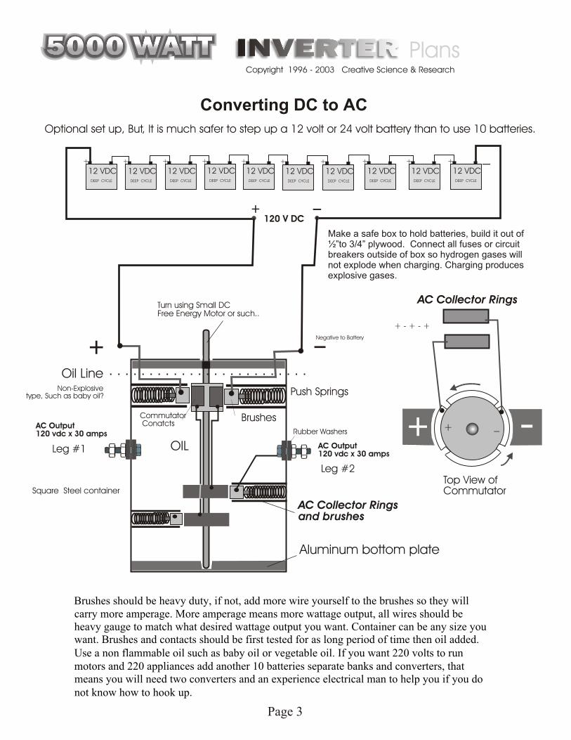
Converting DC to AC
Optional set up, But, It is much safer to step up a 12 volt or 24 volt battery than to use 10 batteries.
+
Make a safe box to hold batteries, build it out of ½”to 3/4” plywood. Connect all fuses or circuit breakers outside of box so hydrogen gases will not explode when charging. Charging produces explosive gases.
Brushes should be heavy duty, if not, add more wire yourself to the brushes so they willcarry more amperage. More amperage means more wattage output, all wires should beheavy gauge to match what desired wattage output you want. Container can be any size youwant. Brushes and contacts should be first tested for as long period of time then oil added.Use a non flammable oil such as baby oil or vegetable oil. If you want 220 volts to runmotors and 220 appliances add another 10 batteries separate banks and converters, thatmeans you will need two converters and an experience electrical man to help you if you donot know how to hook up.
Page 4
Copyright 1996 - 2003 Creative Science & Research
INVERTERINVERTER5000 WATT5000 WATT5000 WATT5000 WATT5000 WATT5000 WATT5000 WATT5000 WATT5000 WATT5000 WATT5000 WATT Plans
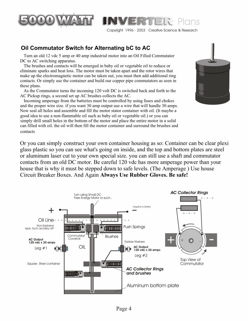
Oil Commutator Switch for Alternating bC to AC
Turn an old 12 vdc 5 amp or 40 amp industrial motor into an Oil Filled CommutatorDC to AC switching apparatus.
The brushes and contacts will be emerged in baby oil or vegetable oil to reduce oreliminate sparks and heat loss. The motor must be taken apart and the rotor wires thatmake up the electromagnetic motor can be taken out, you must then add additional ringcontacts. Or simply use the container and build our copper pipe commutators as seen inthese plans.
As the Commutator turns the incoming 120 volt DC is switched back and forth to theAC Pickup rings, a second set up AC brushes collects the AC.
Incoming amperage from the batteries must be controlled by using fuses and chokesand the proper wire size. if you want 30 amp output use a wire that will handle 30 amps.Now seal all holes and assemble and fill the motor stator container with oil. (It maybe agood idea to use a non-flammable oil such as baby oil or vegetable oil.) or you cansimply drill small holes in the bottom of the motor and place the entire motor in a solidcan filled with oil. the oil will then fill the motor container and surround the brushes and
contacts
Or you can simply construct your own container housing as so: Container can be clear plexiglass plastic so you can see what's going on inside, and the top and bottom plates are steelor aluminum laser cut to your own special size. you can still use a shaft and commutatorcontacts from an old DC motor. Be careful 120 vdc has more amperage power than yourhouse that is why it must be stepped down to safe levels. (The Amperage ) Use houseCircuit Breaker Boxes. And Again Always Use Rubber Gloves. Be safe!
OIL
Oil LineNon-Explosive
type, Such as baby oil?
Leg #1
Leg #2
Negative to Battery
Aluminum bottom plate
Square Steel container
Brushes
Push Springs
Rubber Washers
Turn using Small DC Free Energy Motor or such..
Top View ofCommutator
Commutator Conatcts
_
AC Output120 vdc x 30 amps
AC Output120 vdc x 30 amps
AC Collector Rings
AC Collector Ringsand brushes
+_
+
+ - + - +
+ - + - +
_
+
Page 5
Copyright 1996 - 2003 Creative Science & Research
INVERTERINVERTER5000 WATT5000 WATT5000 WATT5000 WATT5000 WATT5000 WATT5000 WATT5000 WATT5000 WATT5000 WATT5000 WATT Plans
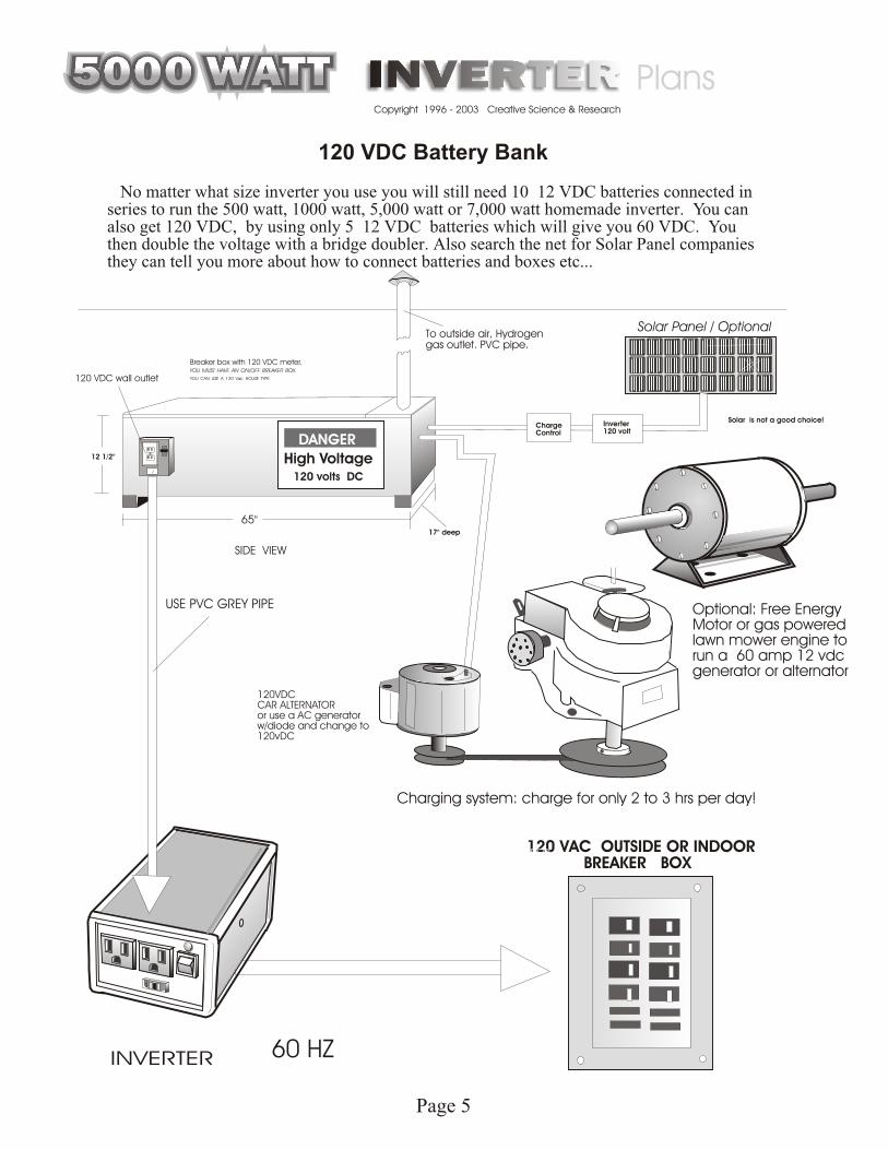
120 VDC Battery Bank
No matter what size inverter you use you will still need 10 12 VDC batteries connected in series to run the 500 watt, 1000 watt, 5,000 watt or 7,000 watt homemade inverter. You can also get 120 VDC, by using only 5 12 VDC batteries which will give you 60 VDC. You then double the voltage with a bridge doubler. Also search the net for Solar Panel companies they can tell you more about how to connect batteries and boxes etc...
To outside air, Hydrogengas outlet. PVC pipe.
12 1/2"
17" deep
Solar is not a good choice!
65"
SIDE VIEW
120 volts DC
High Voltage
DANGER
Solar Panel / Optional
Charge Control
Inverter120 volt
120VDCCAR ALTERNATORor use a AC generatorw/diode and change to120vDC
Charging system: charge for only 2 to 3 hrs per day!
Optional: Free EnergyMotor or gas poweredlawn mower engine torun a 60 amp 12 vdcgenerator or alternator
120 VDC wall outlet
Breaker box with 120 VDC meter.YOU MUST HAVE AN ON/OFF BREAKER BOX.
YOU CAN USE A 120 Vac HOUSE TYPE.
USE PVC GREY PIPE
INVERTER
120 VAC OUTSIDE OR INDOOR BREAKER BOX
60 HZ
FUELLESS HEATER
VIDEO

Copyright 1996 - 2003 Creative Science & Research
INVERTERINVERTER5000 WATT5000 WATT5000 WATT5000 WATT5000 WATT5000 WATT5000 WATT5000 WATT5000 WATT5000 WATT5000 WATT Plans
To outside air, Hydrogengas outlet. PVC pipe.
12 1/2"
17" deep
Solar is not a good choice!
65"
SIDE VIEW
120 volts DC
High Voltage
DANGER
Solar Panel / Optional
Charge Control
Inverter120 volt
120 VDC wall outlet
Breaker box with 120 VDC meter.YOU MUST HAVE AN ON/OFF BREAKER BOX.
YOU CAN USE A 120 Vac HOUSE TYPE.
USE PVC GREY PIPE
12 vdc output, high amp
+
+
+
+
+
+
+
+
_
_
_
_
_
_
_
_
+
+
+
+
+
+
+
+
+
+
+
+
_
_
_
_
_
_
_
_
_
_
_
_
Example of batteriesconnected in series= 120 vdc output
You build at your own risk!
Fuse Box 100 amp?
Fuse Box 100 amp?
INVERTERINVERTERINVERTERINVERTERINVERTERINVERTERINVERTERINVERTERINVERTER5000 Watt5000 Watt5000 Watt5000 Watt5000 Watt5000 Watt5000 Watt
PlansPlansPlansPlansPlansPlansPlansPlansPlans
#579
Page 6

#579
+ _
Ca
pa
cito
r
+ _
Ca
pa
cito
r
+ _
Ca
pa
cito
r
+ _
Ca
pa
cito
r
+ _
Ca
pa
cito
r
To Battery Negative
To Battery POSITIVE
Apply a small motor to shaft and turn
Caps connect and then this is timed to deposit 120 v charge a split second after connect to the load or a 120vdccapacitor reservoir.
LOAD
This is our 5,000 watt inverter design, this is afoundation to work from, of course you can buildit to any wattage you desire. For high wattagesuch as 5,000 watts, you must use fat wire andbrushes, ( Large gauge wire ) this design can alsobe made non-mechanical by using electronicswitching, but we wanted to make it easy for justabout anyone to build. The commutators are veryeasy to build, it may look hard but it is not. Weuse our own design using copper piping and J-Bweld epoxy, both are available at any hardwarestore near you I am sure.
The commutators are simply an on and off switch.
when the commutators hit the front brushes,
the capacitors are charged with 12 volts dc each,
Then as the commutators spin toward the back
they shut off the front 12 vdc charge for the caps
and they then spin around and hit the back brushes,
which connect the capacitors in series and step theVoltage Up tO 120 vdc. The drawings do not show the lullten brushes needed, we did not want to make it iook tocomplicated. _^/ —
Wires are not shown connected to help show brush assembly.
Sorry the drawing does not show the full ten brushes to obtain 120 vdc step up
You will need 10 capacitor and diode banksstacked one on the other. Each capacitor is rated at 25 volts x 23,500 ufa 25 v x 4700 uf = about 100 watts output.
INVERTER OPTION #2
Page 7

#579
J-B Weld Epoxy orPC 7 EpoxyAlso acts as an insulator!
1/8” plastic square washercustom made / same sizeas aluminum / used as ainsulating washer.
Motor Brush w/spring5/16” x 1/4”
½”x ½” steel square 3/4” x 1” copper plate
1/4” x 1 1/4” x 2” long Aluminum
5/16” steel collar,epoxy to commutator
6-32 x 3/8” steel machine screwtapped out w/6-3 NC, drill hole 7/64”
SIDE VIEW
#1#2
The #1 and #2 brushes must not be electrically connected, The epoxy under each steel brush holder will insulate between the steel square pieces and the aluminum. Make sure to spread the surface with an even coat of epoxy. Epoxy glue each steel brush holder assembly to the aluminum brush holder base, part “G”. Then spray paint.
The Brush assembly acts as an on and off switch and must be timed so that the motor runs smoothly and not against it’s self. The commutator is special made, and as the commutator rotates the brushes hit the commutator contact bar making a complete Circuit.
Top View
Plastic Bolts
3/4”
Copper Pipe Commutator
separates the brushesfrom contacting each other.Cut all the way around pipe.
Use a very fine hacksawblade to cut spacers, fill spacers with epoxy and sand smooth.
1 1/8”
1 1/4”
2”
PART “ G”
Type 2 inverter / Brush and commutator assembly
Page 8

Copyright 1996 - 2003 Creative Science & Research
INVERTERINVERTER5000 WATT5000 WATT5000 WATT5000 WATT5000 WATT5000 WATT5000 WATT5000 WATT5000 WATT5000 WATT5000 WATT Plans #579
3/4”
separates the brushesfrom contacting each other.Cut all the way around pipe.
Use a very fine hacksawblade to cut spacers, fill spacers with epoxy and sand smooth.
1 1/8”
Copper Pipe CommutatorJ-B Weld or PC 7 Epoxy fill
#1#2
Back brushes will connecteach capacitor in series tostep up 12 vdc to 120 vdc
Cut Space
Front brushes to charge each capacitor with 12 vdc
Side View
Junction bar that electricity connectsboth brushes just as a switch does.
Page 9

Copyright 1996 - 2003 Creative Science & Research
INVERTERINVERTER5000 WATT5000 WATT5000 WATT5000 WATT5000 WATT5000 WATT5000 WATT5000 WATT5000 WATT5000 WATT5000 WATT Plans #579
Using a Q-Tip, Grease a piece of card board a little larger than the copper pipe diameter, this is so the epoxy will not stick to the Card board surface and can be removed when dry. You now need to fill the copper pipe with Epoxy, so slowly squeeze out enough J-B Epoxy to fill the inside of the copper pipe, follow all directions on the J-B Instructions, Mix the 2 parts very well and start placing the epoxy inside of the copper pipe. Let dry 24 hrs, I prefer to wait 40 hrs, but the instruction do not tell you that. We use J-B Epoxy because it is the best on the market and can stand up to 600 degrees.
Now you must find the exact center of the pipe and score it with a sharp punch. You will be scoring or punching a small hole into the top of the epoxy. Now you are going to need a drill press. Place the copper pipe up as you see in figure #3, Make sure bottom surface is very flat, if it is not the hole will be crooked and the commutator will ride with the shaft crooked and cause a off balance at high speeds. start off with the smallest drill bit you have and work your way up until you have a hole the same size as your shaft rods outer diameter.
STEP FIVE Now using a fine point marker, mark your cut marks on the outside of the copper pipe piece. As shown in figure #4. Use a fine tooth hacksaw to cut.Cut a long center cut all the way around the copper pipe leaving a 3/4” space. Cut all the way through the copper and just up to the hardened epoxy fill. Do not to deep into the epoxy fill.
3/4”
separates the brushesfrom contacting each other.Cut all the way around pipe.
STEP ONE STEP TWO
STEP THREE
STEP FOUR
Use a very fine hacksawblade to cut spacers, fill spacers with epoxy and sand smooth.
1 1/8”
1 3/8”1 3/8”
BUILDING THECOMMUTATORCOMMUTATOR
Cut a piece of 3/4” Diameter” x 1 3/8” length copper pipe that you can buy at any hardware store.
Use a pipe cutter to cut a piece 1 3/8” long.
Next using rough sand paper, sand the inside of the copper pipe really good. And then clean with laquer thinner. Surface must be free from dirt.
This is a homemade Commutator designed by Rick Harrison, This DC Commutator is used to turn off the incoming DC voltage to the HV Voltage or Low Voltage Magnetic Coil. We are going to create a junction bar that rotates and as it rotates it will slide onto the 2 carbon DC motor brushes and cause a complete connection causing DC current to flow into the Electromagnetic coil. We are going to give you 2 options in making a DC motor commutator. Pick which one is easiest for you.
Fill in the cuts with epoxy, let dry 24 hrs then sanddown until smooth. Now take a 5/16” steel shaft and place it back into the epoxy hole, now place asteel 5/16” shaft collar onto the steel rod and epoxy it to the end of your new commutator, ( remove the plastic end first. )
OPTION ONE
Figure #3
Acts as a Junction BarFigure #4
Page 10

#579
PART “A”MOTOR BASEMOTOR BASE
12”
8 ½”
5/16”
5/16”
DRILL SIZE 9/64”BOLT SIZE IS 6/32 X 3/8”
3/4”
3/4”
3 ½”
3 ½”
3 ½”
3 ½”
3 ½”
2 7/8”
2”
½”½”
1 7/8”
2 ½”
The base is made of 1/8” aluminum, for a nice looking research prototype we also recommend ½” plexi glass if you do not wish to use the aluminum. If you are having trouble finding aluminum try your local Machine Shop, for plexi glass ask any Sign shop in your area or check your local yellow pages under plastics. If you did not purchase a kit from us.
Page 11

#579
PART “B”
PART “C”
PART “D & E”
BASE LEGSBASE LEGS
ROTOR SHAFTROTOR SHAFT
ROTOR SUPPORT ARMSROTOR SUPPORT ARMS
Page 12
12”
5/8”
3 ½”3 ½” 3 ½”3/4”
Aluminum 1/8”channel, check hardware stores, steel suppliers, lumber yards. Drill these holes at: Drill holes to 7/64”. You will need a qty of - 2. You will need to tap out each hole, ( Thread it ) using a 6-3 NC tap plug style.
Dril holes to: 7/64”
12”
5/16” steel round rod
1 7/8”
You will need three short pieces, two for the magnets to be used as spacers and one for a Shaft mold for making Commutator.
Part
“ D
“
Part
“ E
“
½”
2 ½”Use ½” aluminum bar. Check at: Machine shops, Steel suppliers in your Yellow Pages, Steel salvage yards etc... Drill two holes on each arm, use a 5/16” drill bit. After you install roller bearing assembly on part “ D “, remove roller bearing and drill a bigger hole using a 11/32” drill bit. On Part “ E “ Drill only halfway through, so the 5/16 rotor shaft can turn on it.
3 3 11/16” 11/16”
4 1/4”
Center Center
Part “ D “ Part “ E “
Roller bearing assembly, Use a large steel washer, assemble this after you put the Rotor shaft and arms together Once your shaft is running through Part “ D “ hole, you can then place the Roller bearing onto it. Grease the outer part of the bearing, Predrill 2 or 3 holes in the large steel washer, place the large washer over top of the roller bearing, center and mark your holes, use a 7/64” drill bit and tape out your holes with a 6-3 NC tap, then attach the washer to Part “ D “ with 6-32 x1 ½” bolts. Now mix up some J-B weld or Pc7 Epoxy and fill theinside beneath the washer and all around the roller bearing. ( Make sure bearing is greased well so you can remove it to later drill your larger hole. The reason you need to dril l a larger hole later is so your rotor shaft can turn more easily. Let epoxy dry for 24 hrs, then remove your Steel washer rollerbearing plate, then remove your roller bearing, drill a bigger hole in Part “D” thenplace you bearing back onto the molded roller bearing assembly.
2 ½”

#579
PART “F”
BRUSH HOLDERBRUSH HOLDER
Page13
ASSEMBLY
#1#2
PART “ G” PART “ G”
1 5/16”
½”
½”
Cut two 1 5/16” x ½” x ½” x 1/16” Square steel.
1 1/4”
1/4”
2”
Fill with PC 7 Epoxy or J - B weld about 1/4” deep.
Brush: grease brush and place inside of square steel part # “F”, Let sit and dry for 24 hrs, then remove brush and clean it off.
PART “F”
PART “F”
PART “F”
PART “F”
+ +
J - B weld or PC 7 EPOXY
Plastic Separator
5/16” x 1/4” Motor BrushCopper holding Plate
As an alternative to using brushes, you could replace with heat treated copper, which has some spring to it. Place the copper on part “ M “ and bend the copper upward.
+ +

#579
PART “M”
HOLDING BARHOLDING BARBrush AssemblyBrush Assembly
Page 14
3” BEND 3” BEND 2 ½”
Use a 8 ½” x 3/4” x 1/16” or best to use 1/8” steel bar. This is used to hold the Brush Assembly.
NOTICE: For a 220 volt dc output simply use two 12 vdc batteries in series and step up.
Commutatorusing copper pipe /J-B Weld
Part
“ M
“
NOTICE: Place brushes in this position, disregard the brush set up in the color photo’s.
PARTS “J”
PART “K”
PART “N”
& NUTSPlastic ScrewsPlastic Screws
ROLLER BEARINGROLLER BEARING
SHAFT COLLARSSHAFT COLLARS
To attache Brush Assembly to holding bar.
Inner Diameter 5/16
You can buy theseat Graingers.comor from a skate shop.
You will need a qty of two. The first shaft collar is to hold the shaft into place, allow a 1/8” space or more between collar and Part “D”The 2nd steel shaft collar is to be epoxied ( Glued ) to one end of the finished commutator.
To fit 5/16” D or buy one and drill it to size 5/16”

Copyright 1996 - 2003 Creative Science & Research
INVERTERINVERTER5000 WATT5000 WATT5000 WATT5000 WATT5000 WATT5000 WATT5000 WATT5000 WATT5000 WATT5000 WATT5000 WATT Plans #579
+ _
Ca
pa
cito
r
+ _
Ca
pa
cito
r
+ _
Ca
pa
cito
r
+ _
Ca
pa
cito
r
+ _
Ca
pa
cito
r
Apply a small free energy motor to shaft and turn
LOAD
LOAD or dump cap
Mechanically stepping up a 12 vdc source to 120 vdc
150 or 200 volt capacitor
x 235,000 uf, or you canconnect 20 50 v x 25,000 ufcaps to make a bank. Or youcan simply eliminate the dumpcap(s) and draw straight fromyour 10 working caps.( We havenever tried that though.) /
If you wish to make a small watt inverter, simply use smallergauge wire and lower rated diodes. The cap dump is optional, wehave tried it on a 100 watt system but have not tried it yet on a5,000 watt system, we use a dump cap. It is expensive but youmaybe able to simply connect your alternating setup directly toyour work caps. If you do so, you will not need a dumpcommutator and brush. This system is very easy to build once youget the hang of it. Please use extreme caution and keep awayfrom children and do not forget to always wear rubber gloves.
The motor to turn the shaft and commutators can be a 1 hp 12 dcfree energy or high efficient motor or you can use solar power.You may want to consider using copper spring brushes as seen onpage 13 they lost longer than carbon brushes. You can then make5 - 1000 watt inverters and connect them to different breakers in
your house.
12 vdc deep cycle marineBattery or 2 - 12 vdc batteries
connected in series to get 220 vdc
WARNING HIGH VOLTAGE
Page 15

Copyright 1996 - 2003 Creative Science & Research
INVERTERINVERTER5000 WATT5000 WATT5000 WATT5000 WATT5000 WATT5000 WATT5000 WATT5000 WATT5000 WATT5000 WATT5000 WATT Plans #579
100 to 5,000 watt inverter / Type 3
There are many ways in which to build a 500 to 5,000 watt inverter by 60 Hz. #1. You can buy an ISOLATION TRANSFORMER 115 V input with a 115 V output. The amperage of the transformer will give you the desired wattage that you will need. an amperage output voltage of 50 amps should do just fine for a 5,000 watt inverter. you can make your own isolation transformer by simply taking apart an old wall transformer and rewinding it. ( same amount of winds for both input and output. ) the size of the wire and how many winds will determine your wattage. the bigger the diameter of the wire the more wattage, But if you wind each side with not enough turns you can burn up the wire or it will get very hot and be less efficient It is best to just buy an ISOLATION TRANSFORMER. ( Remember an isolation transformer does not step voltage up or down, if you put 120 volts in you will get 120 volts out.
Now you must take the isolation transformer and apply a 120 volts DC on/off pulse to the input coil. you should open and shut the + positive side of the 120 vdc at a pulse of 60 times per second. Of course the only way you will know it is 60 Hz is by using a meter that measures Hz. or you can try running a house hold appliance that must run on 60 Hz and adjust the pulse speed that way.
So why pulse the input? ( pulsing = on and off ) If you know anything about electronics you will know that when ever you shut off power to a magnetic coil you will get a reverse polarity! FREE ENERGY FROM A COLLAPSING MAGNETIC FIELD. and by doing this it will cause an AC current to flow to the output of the coil. Size of wire and how many turns you use will determine your output voltage also. If you buy the wrong transformer and you put 120 VDC into it and your only getting an output voltage of 108 VAC, then you can add another 12 VDC battery to increase the input voltage or you can buy and try another ISOLATION TRANSFORMER. they are not that expensive.
To pulse the input voltage you can use a small DC motor to turn a micro switch on and off. for our experiments we used a very small low cost, low amp hobby motor. ( One you would find in toys. ) we then soldered one bead of solder on one side of it's shaft, But it is best to have two beads. or you can use a hard metal glue, epoxy etc... to glue two copper or metal BB's to the shaft or you can use small ball bearings.
Glue
SIDE VIEW
1.5 volt to 6 volt DC electric motor.
bearings or BB'S
Page 16

Copyright 1996 - 2003 Creative Science & Research
INVERTERINVERTER5000 WATT5000 WATT5000 WATT5000 WATT5000 WATT5000 WATT5000 WATT5000 WATT5000 WATT5000 WATT5000 WATT Plans #579
SIDE VIEW
TOP VIEW
ISOLATION TRANSFORMER Coil Turns Ratio 1:1115 V / 115 V x 50 to 100 amps your choice!
Pulsed
120 VDC
1.5 volt to 6 volt DC electric motor.
bearings or BB'S
This small toy motor can be replaced with any size motor you would like to use. this motor pulsing method will also be used in the #3 method of our invention. The wattage and amperage you want your inverter to be the more every component you see below must be heaver duty to match the rated power you are wanting to draw from the batteries. Otherwise components will get hot and can burn up.
MICROSWITCH
Rated at120 VAC90 amps
+
+
115 VAC to 120 VAC out put
MICRO SWITCH
120 vac 80 AMPS
MICRO SWITCH
120 vac 80 AMPS
SIDE VIEW of a Micro Switch
#1
As the shaft motor rotates counter clock wise, the beads come around and hit the micro switch turning it off or on, It's best to buy a micro switch that turns on when pushed. you can also build your own contacts instead of buying a switch. You simply build one using the contact method that you will see in #3. you can use nuts and bolt heads as the contacts, this will increase your amperage rating to a high level, of course if you are an electrical engineer you can clearly see that you can use our methods of stepping up voltage and apply them to solid state circuitry. These plans are intended for those who are not educated in electronic engineering.
Page 17

Copyright 1996 - 2003 Creative Science & Research
INVERTERINVERTER5000 WATT5000 WATT5000 WATT5000 WATT5000 WATT5000 WATT5000 WATT5000 WATT5000 WATT5000 WATT5000 WATT Plans #579
An Isolation Transformer can be used but it is not very efficient yet at this point, As you read on we will show even better ways of making very powerful inverters or even DC step up capacitor transformers, which can also be used as a high or low wattage inverter.
Please build your inverter in a safe container, such as plastic or plywood.Better yet do what we did, we used an old computer box. Try your best to be neat about what you are doing. take your time, do not rush it.
HIGH VOLTAGE CAN KILL YOU! Use rubber gloves! Keep away from children.
The following is an example of how to make a simple capacitor inverter, which can also be used as a DC stepup capacitor type transformer!
Invented by: David Waggoner of Creative Science & Research
WARNING!
WARNING!
Our Step Up Capacitor Inverter
This type of inverter is unlike any you have ever seen before, Although capacitors are used widely in commercial inverters all over the world, We designed this system especially for the back yard researcher in mind, it is simple, low cost compared to buying a $3,000 commercial inverter. You may already have all the parts you need at home in your shop. this type of inverter will use 24 volts DC or you can add more capacitors to allow it to run on 12 volts DC. but for example we will show you the 24 volt DC method only. 24 volts DC is much more safer than using 120 volts DC. there is much less chance of a spark igniting the hydrogen gases and less chance of someone getting shocked to death!
If you do not now what a capacitor is then do not build this inverter yet. Go down to your local Radio Shack and buy a $4 beginners book on electronics called: GETTING STARTED IN ELECTRONICS, ( Page 32 ) This book will also teach you what an SCR is. Most of the parts can be purchased at Radio Shack or purchased by mail catalogs: call these 2 company's and ask them to send you a free catalog. HOSFELT Electronics inc. 1-800- 524-6464 or ALL ELECTRONICS CORP. 1-800-826-5432 Peerless Electronics 1815 s. 7th St. Louisville, KY. 40208 502-637-7674
SO HOW DOES IT WORK? First of all we start with 2 deep cycle marine batteries connected in series to get 24 volts dc. Now we must take that 24 vdc and step it up to 144 vdc, and we will do that by using our new method of using capacitors as batteries, put together in series, EXAMPLE: Charging and using 2 capacitors; ( see page 19 ) Charge #1 capacitor with 24 vdc and charge #2 capacitor with 24 vdc, Now remove the charge and each capacitor now has a full charge of 24 vdc. ( Each capacitor should be taped to your table for this experiment.) now using one alligator clip or wire, connect the + to the - as you would 2 batteries and you will now double the voltage from 24 vdc to 48 vdc. BE CAREFUL DO NOT TOUCH THE ENDS OF THE CAPACITORS. YOU MUST DISCHARGE ALL CAPACITORS WITH A WIRE BY SHORTING THEM OUT OR BY CONNECTING A LOAD SUCH AS A 100 WATT LIGHT BULB.
USING A 24 VDC INPUT
Page 18

Copyright 1996 - 2003 Creative Science & Research
INVERTERINVERTER5000 WATT5000 WATT5000 WATT5000 WATT5000 WATT5000 WATT5000 WATT5000 WATT5000 WATT5000 WATT5000 WATT Plans #579
Please read this it is very important! YOU CAN NOT CHARGE EACH CAPACITOR WITH 24 VDC AND ALSO HAVE THEM CONNECTED IN SERIES ! You must do one or the other never at the same time! 1st you charge each capacitor, then 2nd you disconnect that charge, 3rd you then connect each capacitor ( that now has that powerful 24 volt charge ) and connect them in series. now it would be stupid to connect and disconnect all of this by hand. So what you must do is use switches! You can use all relay switches 1- 4 pole double throw and 5 - 30 amp auto relay switches, or you can use 1- 4 pole double throw relay and 5 - SCR's (Silicon-Controlled Rectifiers.) as switches. ( It is very easy to do!) Using SCR's is much quieter than using loud relays. you can buy low power SCR's at Radio Shack or you can buy High amperage SCR's by catalog. use 70 amp x 200v SCR's for a 1,000 watt unit, or 275 amp x 600 volt SCR's for a 5,000 watt unit. FIGURE #1 is the Charging diagram, this is where you will need to use the 4 pole double throw relay w/1-70 amp SCR on the positive lead, ( Radio Shack type cat. no. 275-214 12 vdc plug in relay. ) This relay is always in the up position, so the capacitors will be charging as soon as you connect the battery to the relay, then when you apply 12 vdc to the coil of the 4 PDT relay it will move the contacts down and this will turn off the charge. All of this will happen very quickly! Because instead of connecting the relay coil to the 12 vdc battery by hand you will be using our MOTOR MICRO SCR SWITCH METHOD The switching must be fast in order to charge the main capacitor bank, which you can apply your load to this, such as a 100 watt light bulb etc... DC only at this point. So you see what we are doing here is eliminating the need to place 10 - 12 vdc deep cycle batteries in series to get 120 vdc. we are simply using capacitors instead. But remember no matter what you do you will always need 10 deep cycle batteries for any average size home. NOTE: You could also build your own relay and use large bolt heads for contacts, and make your own 60 amp 4 PDT contact relay. But its not advisable, Using SCR's as switches work much better!
12 VDC coil 75 ma electromagnet
SPRING
CONTACTS
SIDE VIEW OF 4 PDT RELAY
FRONT VIEW OF RELAY
COIL 12 v INPUT +
1 2 3 4
5 6 7 8
9 10 11 12
13 14
+ _
25000 uf 50v 25000 uf 50v
Electrolytic Capacitor
CONNECT WIREAFTER CHARGE
OUTPUT
Electrolytic Capacitor
Charged to 24 vdc Charged to 24 vdc
+ +_sw _
48 vdc
We Strongly Recommend that you Build a 100 watt inverter first using relays. Use 120 VDC to light a bulb!
THIS IS WHAT A RELAY LOOKS LIKE
Page 19
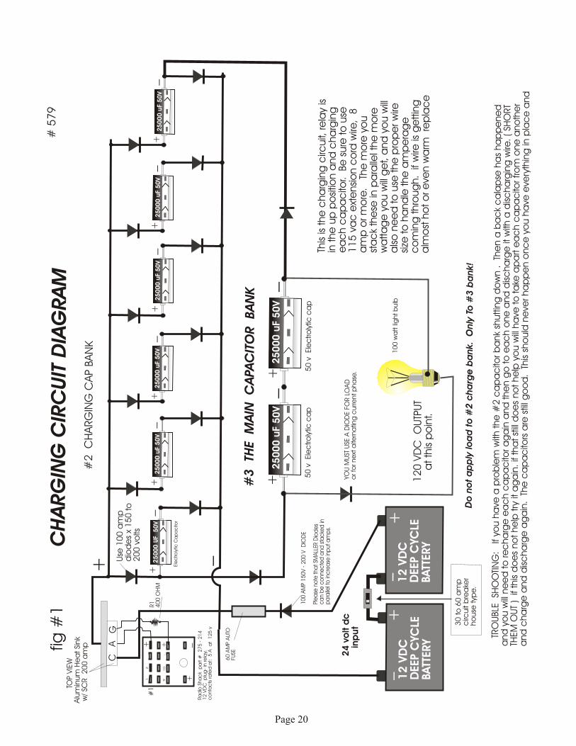
fig #
1#
57
9C
HA
RG
ING
CIR
CU
IT D
IAG
RA
M
#2
C
HA
RG
ING
CA
P B
AN
K
#3 TH
E M
AIN
C
APA
CIT
OR
BA
NK
25000 U
F 5
0V
Ele
ctro
lytic
Ca
pa
cito
r
+_
25000 u
F 50V
+_
25000 u
F 50V
+_
25000 u
F 50V
+_
25000 u
F 50V
+_
25000 u
F 50V
+_
25000 u
F 50V
50
v
Ele
ctro
lytic
ca
p
+_
25000 u
F 50V
50
v
Ele
ctro
lytic
ca
p
+_
+
#1
1
2
3
4
9
10
1
1
12
+_+ +
12 V
DC
DEE
P C
YCLE
BATT
ERY
12 V
DC
DEE
P C
YCLE
BATT
ERY
_6
0 A
MP A
UTO
FUSE
10
0 A
MP
15
0V -
20
0 V
D
IOD
E
Ple
ase
no
te tha
t SM
ALL
ER D
iod
es
ca
n b
e c
onne
cte
d a
nd
sta
cke
d in
p
ara
llel t
o in
cre
ase
inp
ut a
mp
s.
Ra
dio
Sha
ck
pa
rt #
2
75
- 2
14
12
VD
C
plu
g-
in re
lay.
c
onta
cts
ra
ted
at:
5 A
a
t 1
25
v
++++
____
YOU
MU
ST U
SE A
DIO
DE F
OR L
OA
Do
r fo
r ne
xt a
ltern
atin
g c
urre
nt p
ha
se.
12
0 V
DC
O
UTP
UT
at th
is p
oin
t.
10
0 w
att li
ght b
ulb
This
is the
cha
rgin
g c
ircuit,
re
lay
is
in the
up
po
sitio
n a
nd
cha
rgin
g
ea
ch c
ap
ac
itor.
Be
sure
to
use
1
15
va
c e
xte
nsi
on c
ord
wire
, 8
a
mp
or m
ore
.
The
mo
re y
ou
sta
ck
the
se in
pa
ralle
l the
mo
re
wa
tta
ge
yo
u w
ill g
et, a
nd
yo
u w
ill
als
o n
ee
d to
use
the
pro
pe
r w
ire
size
to
ha
nd
le the
am
pe
rag
e
co
min
g thro
ug
h.
if w
ire is
ge
ttin
g
alm
ost
ho
t o
r e
ven w
arm
re
pla
ce
24 v
olt d
c in
pu
t
Do
no
t a
pp
ly lo
ad
to
#2 c
ha
rge
ba
nk. O
nly
To
#3 b
an
k!
T
RO
UBLE
SH
OO
TIN
G:
If
you h
ave
a p
rob
lem
with
the
#2
ca
pa
cito
r b
ank
shuttin
g d
ow
n .
Th
en a
ba
ck
ca
lap
se h
as
ha
pp
ene
d
and
yo
u w
ill n
ee
d to
re
cha
rge
ea
ch c
ap
ac
itor a
ga
in a
nd
the
n g
o to
ea
ch o
ne
and
dis
cha
rge
it w
ith a
dis
cha
rgin
g w
ire.
( SH
ORT
THEM
OU
T ) if
this
do
es
no
t he
lp try
it a
ga
in.
if th
at st
ill d
oe
s no
t he
lp y
ou w
ill h
ave
to
ta
ke a
pa
rt e
ac
h c
ap
ac
itor fro
m o
ne
ano
the
r a
nd
cha
rge
and
dis
cha
rge
ag
ain
. T
he
ca
pa
cito
rs a
re s
till g
oo
d.
This
sho
uld
ne
ver ha
pp
en o
nc
e y
ou h
ave
eve
ryth
ing
in p
lac
e a
nd
CA
G
R1
40
0 O
HM
T
OP V
IEW
Alu
min
um
He
at Si
nk
w/ SC
R
20
0 a
mp
Use
10
0 a
mp
dio
de
s x
15
0 to
2
00
vo
lts
30
to
60
am
pc
ircuit
bre
ake
rho
use
typ
e.
Page 20

fig #
2C
HA
RG
ING
CIR
CU
IT D
IAG
RA
MA
LL C
ON
NEC
TIO
NS
MU
ST B
E S
OLD
ERED
WELL
Co
ntin
ue
d fro
m p
ag
e 1
0 fig
#1
N
ow i
t is
tim
e to
con
nect
the
pul
ser
mot
or s
wit
ch.
Thi
s is
on
/ o
ff s
et u
p us
ing
a sm
all
reed
sw
itch
, ( D
oor
alar
m s
wit
ch )
it
wil
l be
use
d to
tur
n po
wer
on
and
off
to t
he r
elay
coi
l, t
his
w
ill
caus
e th
e el
ectr
omag
net
to c
ome
on a
nd o
ff, t
his
wil
l al
so
caus
e th
e co
ntac
t ar
m t
o m
ove
up a
nd
dow
n. S
ee a
lso
page
6
and
7. S
o w
hen
the
rela
y co
il i
s of
f th
e ca
paci
tors
are
ch
argi
ng,
and
whe
n i
t is
on,
it
mov
es t
he c
onta
ct a
rm d
ow
n an
d di
scon
nect
s th
e 24
vdc
bat
tery
so
it w
ill
no l
ong
er c
harg
e. N
ow
whe
n i
t is
in
the
dow
n po
siti
on, i
t w
ill
turn
on
the
pow
er
to t
he 5
sm
all
reed
rel
ays
in F
ig #
3. C
ausi
ng a
ll 5
SC
R's
to
S
O W
HA
T D
OE
S S
TA
CK
ING
ME
AN
? I
t m
eans
ju
st w
hat
it s
ound
s li
ke, y
ou s
tack
In
para
llel
. If
you
hav
e a
har
d ti
me
in y
our
area
fin
ding
ca
paci
tors
or
diod
es t
hat
are
rate
d th
at h
igh
then
yo
u ca
n bu
y ch
eap
ones
an
d st
ack
them
. its
muc
h e
asie
r th
ough
if
you
buy
the
rat
ing
you
need
.ex
ampl
e; s
tack
eac
h di
ode
or c
apac
itor
on
top
of t
he o
ther
and
co
nnec
t th
em i
n pa
rall
el.
Exa
mpl
e: I
f yo
u s
tack
2 -
35
amp
x 1
50 v
dio
des
in
para
llel
you
wil
l ge
t a
70 a
mp
outp
ut. t
he
sam
e w
ith
capa
cito
rs. y
ou d
oub
le
your
am
per
age
and
wat
tage
.
FR01FR01 FR01FR01
DIO
DES
Sym
bo
l fo
r D
iod
es
SID
E V
IEW
SMA
LL R
ARE E
ARTH
MA
GN
ETS
Glu
e to
alu
min
um
-ep
oxy
12
VD
C
inp
ut fro
mo
ne
of th
eb
atte
ries
1.5
vo
lt to
6 v
olt
DC
ele
ctric
mo
tor.
SMA
LL A
LUM
INU
M B
LOC
KG
LUE
TO S
HA
FT-
EPO
XY
This
wire
ca
n b
e s
ma
ll,
It o
nly
ta
kes
ab
out 7
0m
a
to run the
co
il o
f th
e re
lay.
Re
ed
sw
itch/ Ra
dio
Sha
ck
ala
rm s
witc
hty
pe
-fo
r d
oo
r a
larm
s.
+ _
+
As
the
shaf
t m
otor
rot
ates
cou
nter
clo
ck w
ise,
the
mag
net
com
es a
rou
nd a
nd t
urn
s on
the
ree
d s
wit
ch t
urni
ng i
t of
f an
d on
, y
ou
can
repl
ace
thi
s pu
lse
reed
an
d m
oto
r sw
itch
wit
h a
n el
ectr
onic
on
/ of
f sy
stem
. ( a
pul
ser
gen
erat
or )
( i
t is
in
the
elec
tron
ics
beg
inne
rs
book
I t
old
you
abo
ut e
arli
er.
by
buil
ding
an
elec
tron
ic o
n /
off
pul
ser
to r
epla
ce t
he R
eed
Sw
itch
, the
uni
t w
ill
be
muc
h q
uiet
er.
Als
o p
lace
man
ual
on /
off
sw
itch
es w
here
nee
ded
so y
ou
can
pow
er u
p y
our
inve
rter
and
tur
n it
off
. You
wil
l ac
tual
ly n
eed
2 re
ed
and
mot
or s
wit
ches
, thi
s on
e is
the
fir
st. a
nd t
he 2
nd o
ne i
s us
ed f
or a
lter
nat
ing
the
dc t
o ac
usi
ng a
not
her
rela
y an
d 20
0 am
p S
CR
's.
it i
s al
l re
ally
ver
y si
mpl
e an
d no
t th
at h
ard
or e
xpen
siv
e to
bui
ld.
1 a
mp
dio
de
Va
riab
le re
sist
or sp
ee
d w
itch
#3 TH
E M
AIN
C
APA
CIT
OR
BA
NK
25000 U
F 5
0V
Ele
ctro
lytic
Ca
pa
cito
r
+_
25000 u
F 50V
+_
25000 u
F 50V
50
v
Ele
ctro
lytic
ca
p
+_
25000 u
F 50V
50
v
Ele
ctro
lytic
ca
p
+_
+
#1
1
2
3
4
9
10
1
1
12
+_+ +
12 V
DC
DEE
P C
YCLE
BATT
ERY
12 V
DC
DEE
P C
YCLE
BATT
ERY
_
++++
____
YOU
MU
ST U
SE A
DIO
DE F
OR L
OA
Do
r fo
r ne
xt a
ltern
atin
g c
urre
nt p
ha
se.
12
0 V
DC
O
UTP
UT
at th
is p
oin
t.
10
0 w
att li
ght b
ulb
24 v
olt d
c
in
pu
t
CA
GU
se 1
00
am
pd
iod
es
x 1
50
to
20
0 v
olts
We
are
try
ing
to
ma
ke this
sim
ple
so
anyo
ne
ca
n b
uild
this.
If it
is s
till
to m
uc
h fo
r yo
u.
we
are
so
rry
we
ha
ve d
one
the
be
st w
e c
an fo
r no
w.
TH
E O
N/O
FF P
ULSER
SW
ITC
H F
OR
RELA
Y
+
Page 21

The following page shows the use of SCR’s to connect the charged capacitors in series to step up the incoming 12 vdc or 24 vdc current.
Please notice that you can use 4 PDT relays to do the same thing which we have fully tested and found the relays do great! We have not fully tested the SCR’s yet, but we have done some bench test’s and the SCR’s look like they will work just fine. If they do not you may know of a better way, please let us know because we do not have the time right now to test and develop the use of SCR’s, We are working on more important projects.
Thank youDavid Waggoner
Low amp 4PDT Relay Switches
Low amp 4PDT Relay Switches SCR’s High amp for switching
SCR’s High amp w/heat sink aluminumHigh Amp 4PDT Relay SW
Page 22

fig #
3C
ON
NEC
TIN
G C
APS IN
SER
IES
FRO
NT
VIE
W O
F RELA
Y
#1
25000 u
f 5
0v
Ele
ctro
lytic
Ca
pa
cito
rC
ase
typ
e w
ill b
e m
uc
hla
rge
r w
ith b
olt
typ
ec
onne
cto
rs.
+_
25000 u
f 5
0v
+_
25000 u
f 5
0v
+_
25000 u
f 5
0v
+_
25000 u
f 5
0v
+_
25000 u
f 5
0v
+_
1
2
3
4
56
9
10
1
1
12
+_+ +
_ _
Ra
dio
Sha
ck
pa
rt #
2
75
- 2
14
12
VD
C
plu
g-
in re
lay.
c
onta
cts
ra
ted
at:
5 A
a
t 1
25
v
++__
CA
N
ow a
s se
en i
n p
age
11, W
hen
the
rela
y is
tur
ned
on, t
he
rela
y ar
m w
ill
mov
e do
wn
and
out
of
char
gin
g po
siti
on a
nd
wil
l m
ove
to #
5 a
nd #
9 re
lay
pos
itio
n as
sho
wn,
thi
s w
ill
swit
ch o
n th
e S
CR
'S, a
nd w
ill
conn
ect
each
24
volt
cha
rged
cap
acit
or i
n
seri
es a
nd g
ive
you
an o
utpu
t of
144
vo
lts.
A
gain
thi
s w
ill
char
ge #
3 T
he M
ain
Cap
acit
or B
ank
( a
s se
en o
n p
age
13. )
Yo
u ca
n r
epla
ce w
ith
12 v
dc 3
0 am
p a
uto
rela
ys. b
ut i
s no
t ad
visa
ble
WA
RN
ING
: ne
ver
char
ge a
nd t
urn
on
the
SC
R's
at
the
sam
e ti
me!
It
wil
l bu
rn u
p y
our
SC
R's
. T
his
is
why
we
use
a re
lay
swit
ch #
1. E
ven
thou
gh
the
rela
y w
ill
be s
wit
chin
g ve
ry f
ast,
the
ch
argi
ng a
nd t
he S
CR
's w
ill
be o
n at
dif
fere
nt t
imes
. If
yo
u ar
e g
oing
to
buil
d an
inv
erte
r th
at u
ses
muc
h le
ss w
atta
ge, T
hen
agai
n al
l of
the
se p
arts
can
be
purc
hase
d at
any
Rad
io S
hac
k st
ore
. N
ote:
For
tho
se o
f y
ou w
ho d
o no
t kn
ow w
hat
an S
CR
is,
It
is a
Sil
icon
-Con
trol
led
Rec
tifi
er. Y
ou c
an m
ove
a l
arge
am
oun
t of
cur
rent
wit
h ju
st a
ver
y sm
all
amou
nt o
f cu
rren
t ju
st i
n th
e m
illi
amps
, to
tu
rn o
n th
e sw
itch
to
allo
w t
he
very
lar
ge c
urr
ent
to f
low
. You
can
buy
6 a
mp
SC
R's
at
Rad
io S
hac
k, P
lay
wit
h th
ese
firs
t, a
nd l
earn
and
the
n bu
y th
e ex
pens
ive
SC
R's
tha
t yo
u w
ill
nee
d f
or
5,0
00 w
atts
. B
uy 2
75 a
mp
X 6
00 v
olt
SC
R's
fo
r a
5,0
00 w
att
unit
. L
ook
in
yo
ur y
ello
w p
age
phon
e bo
ok f
or e
lect
ron
ic s
uppl
iers
. I
foun
d 27
5 am
p S
CR
's a
s lo
w a
s $
60
ea.
Th
ese
cap
acit
ors
are
the
sam
e ca
paci
tors
as
seen
on
pag
e 10
, w
e di
d
not
dra
w i
n th
e o
ther
cha
rgin
g co
nnec
tion
s so
you
wo
uld
not
get
con
fuse
d, I
t w
ould
loo
k li
ke
a b
unch
of
spag
hett
i, o
f co
urs
e th
is c
ircu
it
and
the
circ
uit
on p
age
10 w
ill
all
be h
ooke
d to
geth
er, I
t w
ill
be t
he j
ob
of t
he 4
PD
T r
elay
to
keep
the
m s
epar
ate.
We
are
tryi
ng t
o m
ake
this
as
sim
ple
for
ever
yone
as
poss
ible
Thi
s ty
pe
of s
tep
up t
rans
form
er /
inv
erte
r w
orks
ver
y w
ell.
the
cap
acit
ors
and
diod
es w
ill
last
a l
ife
tim
e!
C
C =
Ca
tho
de
, A
= A
no
de
, G
= G
ate
. S
ee
Ra
dio
Sha
cks
ge
ttin
g s
tarte
d in
ele
ctro
nic
s b
oo
k. it
will te
ll yo
u a
bo
ut SC
R's
27
5 a
mp
sx
30
0 -
60
0 v
TO-2
20
ca
seo
r w
ha
t e
ver
your su
pp
lyho
use
ha
s.
Ho
le fo
r bo
lt a
nd n
ut to
atta
ch
to a
lum
inum
he
at s
ink.
hea
t sin
k c
an
be
sq
uare
or a
ny s
ize
yo
u w
ant
, it i
s th
ere
to h
elp
kee
p th
e S
CR'
s c
oo
l.
SCR
A
G
12
vd
c
FAN
+ -
Dio
de
Ra
ted
20
0 a
mp
by
20
0 -
60
0 v
olt
( Yo
ur C
ho
ice )
Sma
ll M
illia
mp
Re
ed
Re
lay
Switc
h1
2 v
dc
SP
ST
+-
To 1
2 v
dc
Ba
tte
ryAlu
min
um
He
at Si
nk
SCR
27
5 a
mp
s x
30
0 to
60
0 v
40
0 to
50
0o
hm
re
sist
or
CA
G
+
CA
G
+
CA
G
+
CA
G
+
CA
G
+
Your SC
R M
ay
loo
k So
me
thin
glik
e this.
De
pe
nd
ing
on w
ha
t si
ze y
ou b
uy.
Exa
mp
le o
nly
Top
Vie
w
Sid
e V
iew
Co
pyr
ight 1
99
8Pa
tent Pe
nd
ing
LOW
CO
ST
.69
Page 23

#579
For low wattage applications try this below.. For High wattage use the oil drum brush and commutator method. So you have built everything up to this point and you have even lit 100 watt light bulbs with your new 120 VDC STEP UP CAPACITOR TRANSFORMER. Well it's great for lighting bulbs and running electric heaters, but now you want to run much more, such as TV's, VCRs etc... that use AC. ( NOTE: you can take the AC coil transformers out of each appliance and step down the DC voltage to the required voltage and amps and run on 120 VDC. )
So what we must now do is take that 120 VDC and turn it into 120 volts AC. Which is very simple to do. You can do this electronically or you can do it mechanically by using a store bought 2PDT relay or by building your own relay. We suggest you build your own relay, see bottom drawings. NOTE: If you are not getting 120 VAC output but the voltage is much less, then you must increase the 120 VDC output to a higher voltage until your alternator method is outputting 120 VAC.
#3 THE MAIN CAPACITOR BANK
4700 uF 50 v
50 v Electrolytic cap
+ _4700 uF 50 v
50 v Electrolytic cap
+ _
++
YOU MUST USE A DIODE FOR LOAD
120 VDC OUTPUT
120 VDC INPUT
( THIS IS FOR METHOD #2 THE CAPACITOR INVERTER )
From page 10 fig #1
1 2
3
5 6
A B
4
+
+
-
-
+ _
_
_+
+120 VACOUTPUT 60 HZ
SIDE VIEW
SPEED CONTROL TO GETDESIRED 60 HZ
1.5 volt to 6 volt DC electric motor.
+
+
12 VDCDEEP CYCLE
+ _
From same 24 vdc battery bank.
fig #4
DC to AC Alternator Inverter
Reed Switch, High amps.
Notice: This relay and this motor switch system is not the same as the first. so when you buy your parts you are going to need;
Qty- 2 reed door switchesQty-2 Hobby Motors w/ ma- gnets.
Page 24

#579
Type III CAPACITOR INVERTER
25000 uf 50v 25000 uf 50v+ + _25000 uf 50v 25000 uf 50v+ + _
25000 uf 50v 25000 uf 50v+ + _
+ + + + + +
- - - - - -
+
_
Positive Brush
PositiveContacts
NegativeContacts
Negative Brush
A
B
144 VDC Output
To start; Instead of connecting and disconnecting capacitors in series as you may have seen in our type II Capacitor Inverter, In this new method you simply keep all caps connected in series as shown in figure #1. Fig. #1 is to help you get an understanding of how it works. The positive and the negative brushes slide over the contacts, moving together, creating a 24 VDC charge in each capacitor. For this simple experiment you will need to connect 6 - 50 Volt x 2200 or 25,000 uf capacitors together in series. ( solder all connections.) Now tape down the caps flat onto a table top, Now cut 12 pieces of thick or thin ( thick is best! ) copper or aluminum to 1 1/2" x 3/4" squares and tape them down as shown in figure #1. Now solder your wire to the contacts and the caps as shown. Now using rubber gloves place the positive ( 16 gauge wire automotive type ) A Brush onto the first + contact and the negative B brush on the negative contact Now slide wires down the rows at the same time and at the same speed to charge each capacitor at 24 VDC. Slide and charge all the way to #6 cap. So you have now charged all caps and your DC volt meter should now read 144 VDC. ( Be careful not to touch, it can KILL! Use rubber gloves. )
Now at this point no load is connected. Always connect load or a 120 VDC cap bank x 25,000 uf AFTER YOU HAVE CHARGED CAPS, To avoid large sparks that can burn up your contacts. So again after you charge 144 VDC cap bank you then use a magnetic reed switch to turn on load.
A and B brushes move at the same time, moving all the way to the right to #6 cap and a little past #6, and if you will picture a magnet connected to your wrist that will then switch on the magnetic reed switch to power the load or charge your 120 VDC cap bank. Reed switch rated at 5 to 10 amps. Now if you will picture the contacts on a round stationary piece of plywood board and a rotor arm that turns with the brushes on it. to make contact with the cap contacts.
TAPE
TAPE Etc....as so.
OPTIONAL: Here is another way that you can make a high voltage inverter. Can be done mechanically or by using SCR’s or Transistor.
Page 25

#579Type III CAPACITOR INVERTER
25000 uf 50v 25000 uf 50v+ + _25000 uf 50v 25000 uf 50v+ + _
25000 uf 50v 25000 uf 50v+ + _
7" diskSpace for magneticreed switch or switchesmagnet connects to rotor that turns.This plywood board does not turn.
+
+
+
+ +
+
__
_ _
__
#4
#7
Connect wires to caps
Epoxy Glue all + and - contactsto plywood.
Drill holes
1
2
3 4
56
7
89
10
1112
+_
+
+
_
_
1. 2. 3. 4. 5. 6. 7. 8. 9. 10. 11. 12.
PENCIL MARKS
Now as #7 rotor arm moves counter clockwise, it moves the contact brushes over 1 & 2 and so on. this all happens at a high rpm. ( You can try with lower Rpms to meet your needs.) The #4 brush is actually a set of brushes with 2 round commutators, the same commutators you would see in a AC motor, ( Not a DC motor!) the 24 VDC from the batteries travels through the #4 set of + and - brushes and travels through the 2 separate round commutator contacts, up through the 2 wires, through the brushes and onto the stationary contacts. Then to the capacitors charging them at 24 VDC each = 144 VDC. The commutator can be simple, using a 2 washer's a plastic spacer to protect from shaft, and some epoxy glue. or place a flat type onto the moving rotor arm.
+
+
_
_
Shaft
Rotor #7 arm
+
Front View Of washer
__ +
+ + _Shaft
wood
Metal Washer Commutators
144 VDC
Below is a crude mechanical way to replace the relays if you are on a very tight budget.
Page 26

#363-AType III CAPACITOR INVERTER#3
2500
0 uf
+
2500
0 uf
+
2500
0 uf
+
2500
0 uf
+
2500
0 uf
+
2500
0 uf
+
+
+ +
+
#4
#7
Connect wires to caps
Roofing Nails with large heads
_
4,025 VDC
DUMP CHARGE
DangerHigh Voltage!
35 + nail heads = 35 200 v caps= 4,025 VDC
65 + nail heads = 65 200 v caps= 7,475 VDC
Use 35 to 65 of the upright caps, they are cheaper to buy and easier to mount that many caps. Use roofing nails with large heads and nail them into plywood board. now sand heads and the points until shiny. now solder all nails at points to the capacitors. see page 16. The amount of high voltage and amperage is unlimited. this is very easy to build!
Is great for a step up High voltage source for our plans #500, #362, #459, etc...
Output Amperage will depend onthe size of your capacitors you decideto use. The higher the uf, the higherthe amps! High Voltage x High amps!
INPUT is 115 vdc: Use a 12 volt DC battery connected to a 500 watt INVERTER ( Which we sell if you need one.) that will step up the 12 VDC to 115 VAC 60 Hz.Now use a 150 v volt to 200 volt Diode to change 115 VAC to DC. Or for a greater input of 200 VDC build a Voltage doubler with caps. see our high
Caps rated at: 200-250 volts
Here is another crude mechanical way to replace the relays if you are on a very tight budget.
Page 27

5,000 WATT INVERTER #579
Our 5,000 WATT INVERTER
A SIMPLE WAY TO ALTERNATE A DC CURRENT
Well you know how to build the 120 VDC battery bank by now. so now lets go on to understanding and building a way to alternate that 120 VDC to AC.
First I will show you a simple low wattage way to alternate the DC. By using a radio Shack 2 pole double throw 12 vdc relay. The relay is rated at 5 amps so relay contacts will not burn out unless you go over 5 amps. which makes this a good 100 watt inverter. See figure one. the top two input connections you simply connect to the 120 vdc battery bank. use a 5 amp 120 volt diode for the positive side of battery. use a 5 or 10 amp fuse. Use the proper wire size so your wire will not burn up when load is applied. Now connect another of the same to the 2nd output but put the + side to the right and the - side to the left. ( Be sure to use another 5 amp diode and fuse. now when a 12 vdc on and off pulse ( 60 Hz ) is applied to the coil of the relay. this causes the common arm to move up and down, which in turn is alternating the DC current to an AC square wave. You can build this large enough to handle as much wattage as you desire, By building your own large scale homemade 2 pole double throw relay switch. Contacts should be made very large and changeable. They can be made with large bolt head rounded off. this same method can be done with a small low amp relay and by using high amp transformers or SCR's. you will never need to change contacts. The transformer or SCRs take the beating. They will get hot so use a 12 vdc fan to cool them. make sure they are connected to a aluminum heat sink.
+
12 VDC pulse inputs
COMMON
First Input
Front View of 2pdt relay
Figure 1
Second Input
120 VAC OUTPUT
+
When common lead contacts are in the up position + & - flow through output. and when in the down position it turns off the up position and reverses polarity in the output as - & +. But this is done very fast!at 60 Hz.
The output is 120 VAC 60 hzsquare wave. a square wave can run many things such as AC motors and such. try it. or if you want a modified sine wave which is very close to what you get from the electric company, then you will need to run the 120 VAC through a 3-10 amp transformer 1:1 or you can use transformers to multiply the wattage.
Page 28

5,000 WATT INVERTER #579
+
12 VDC pulse inputs
Front View of 2pdt relay
Figure 1
+
+
12 VDC pulse inputs
Front View of 2pdt relay
+
12 VDC coil 75 ma electromagnet
SPRING
CONTACTS
SIDE VIEW OF 4 PDT RELAY
THIS IS WHAT A RELAY LOOKS LIKE
SIDE VIEW
to 12 VDC battery
1.5 volt to 6 volt DC electric motor.
bearings or BB'S
MICROSWITCH
12 VDC BATTERY
MICRO SWITCH
120 vac 80 AMPS
MICRO SWITCH
120 vac 80 AMPS
SIDE VIEW of a Micro Switch
+
This is an easy way to pulse the relay to 60 Hz, ( If you do not know how to make a 60 Hz pulse electronic generator. ) Please note that the 2pdt relay can be replaced by using 200 amp x 30 to 70 amp Transistors or SCR's. You use them in the same way as switches. and then use a small low amp 2pdt relay to switch them on and off. This way the SCRs or the power Transistors take all the amperage punch!and you wont have to worry about your contacts burning out.
Page 29

#579THE CAPACITOR INVERTER
The DPDT relay is being used to alternate the DC current. When contacts are in the up position +& - position current runs through the 120 vac out put wire, and when the relay is turned on by 12 vdc 15 ma, the polarity reverses in the wire to - & + , this all happens very fast and creates ALTERNATING CURRENT TO THE OUTPUT! again as the small DC pulse motor is running it switches on and off a reed switch causing the relay contact arm to move to upper contacts and then to the lower contacts. Now getting back to the relay, It is best to build your own DPDT 275 amp relay. You can make the contacts changeable. The contacts can be made of bolt heads. For best results sand and round off top of bolt heads. You must find very large bolts and nuts to take that much amperage. Once you have it built you can have it working vertical dipped in a oil bath. Do not dip electromagnet coil into oil, it will short out! Just the contacts.
DPDT = Double pole, Double throw
10 - 20 amp wire connectingthe upper and lower arms.
PLYWOOD
PLYWOOD
METAL
METALSPRING
ATTACH WIRES TO HERE
METAL
+
_
Bolt heads used ascontacts.
WOOD SCREWS
WOOD
AC Output
AC Output
Metal Angle iron or aluminum
24 vdc Electromagnet500 turns of #26 copper coated wire
PLASTIC OR HARD WOOD
METAL ANGLE ALUMINUM
Contact rocker arms
TOP VIEW
front view of relay
SIDE VIEW
+
+
_
_
+ -
Homemade Changeable Contact Relay
copyright 1998
Page 30

#579THE HOMEMADE RELAY INVERTER#3 Method
METAL
METAL
+
_
SIDE VIEW
By now you may have figured out how to build the #3 inverter method, This is by far the most simplest and easiest way to build an inverter, BUT IS ALSO THE MOST DANGEROUS WAY! again be very careful high voltage can kill!
By using the 120 VDC battery bank on page 2 , and using the homemade DPDT relay on page 14, You will be able to build the most powerful inverter of all, If you use your brain you will soon learn you can get much more than 5,000 watts from this method of invention.
If you have no load there will be no spark on the contacts, When a load is applied a spark will appear and a break down of the bolt head contacts will begin, the greater the load the faster the contacts will wear. contacts can last a long time. But one should employ a safety net just in case the contact stick together, this will cause 120 VDC to try and run your AC appliances, although I do not believe at all that it will hurt them, But you will get a humming noise coming from there AC transformer or AC motors from the AC appliance, or you may not get a humming noise at all, the AC appliance will simply stop working but all light bulbs in your house will continue to work since they can be run on AC or DC current.
5,000 WATT INVERTER
+
12 VDC DEEP CYCLE
+
12 VDC DEEP CYCLE
+
12 VDC DEEP CYCLE
+
12 VDC DEEP CYCLE
+
12 VDC DEEP CYCLE
+
12 VDC DEEP CYCLE
+
12 VDC DEEP CYCLE
+
12 VDC DEEP CYCLE
+
12 VDC DEEP CYCLE
+
12 VDC DEEP CYCLE
_
120 V DC+ _
You can encase this in a simple plywood box or get as fancy as you want. You can purchase plastic boxes from the catalogs I told you about.. be sure to put a 120 v light on front panel with a volt meter, and please do not try and run this without its own separate fuse box. you can use 120 VAC fuse boxes that you can buy at any hardware store. PLEASE BE NEAT AND CAREFUL.
Page 31

#579 Update 5,000 watt inverterSorry for the inconvenience, But we left something out Of our #579 plans and have not had the time to redo them yet.
This update is for the possible 5,000 watt SCR inverter type.
After you have study these plans a bit, you will understand what I am going to tell you. On the Charging Circuit Diagram. Up on the top left hand of the page is a SCR, This is not hooked up right. The positive + side of the battery is connected to the A of the SCR not the C. and the output is connected to the C not the A of the SCR. ( Just Reverse that )
Now every SCR once it is switched on will stay on until the power going through it is turned of. But we found out you can turn off a SCR without harming it, by shorting out C & A. Therefor you will need an on/ off reed switch for every SCR, ( Which we failed to show in the plans.) Also the delay switch part # 275-214, is no longer needed. It will be replaced by a special homemade Disk switch device. ( It is the only way to do it. they did not make relays to do what we need to do. ) The disk turns and is powered by a low amp DC motor. The disk has a total of 8 door reed switches rated at 2-30 amps. 4 of the reed switches is to turn on and off the Charging SCR on page 10 and the SCR's on page 12. The other 4 reed switches are to turn the 4 SCR's on and off on page 14-A, ( To alternate the current. ) Now looking at page 12, you will need 5- SPST reed relay switches for each SCR. ( rated at not under 1 amp. ) They will be turned on and off using the + side of battery # 4 reed door switch to turn off each SCR at the same time.
The reason we use SCR's in the first place is because they can transfer a very large amount of power and take very well. ( They take a licken and keep on ticken! ) Transistors or mosfets could be used to replace the SCR's and would be much easier to work with eliminating the need for a On/Off homemade disk. you could then use relays. and you would not need 5-SCR shut off relays. But you would have a much lower watt inverter. We are still working out some small bugs. If any of you out there have any good ideas please write me.
Strong Magnet connectedto moving disk.Reed door alarm switches or such.
1
2
3
4
5
67
8
front viewC A
SCR OFF
SW
SCR CHARGER
SCR CHARGER
SCR CAP BANK pg 12.
SCR CAP BANK pg 12.
ON
OFF
ON
OFF
The Wheel/disk turns as does the strong permanent magnet, The reed switches do not. Turn wheel using a low power DC high eff. Or Free Energy motor connected to a speed control.
#5, 6, 7 and 8 are used in the same
Page 32

INVERTERINVERTER5000 WATT5000 WATT5000 WATT5000 WATT5000 WATT5000 WATT5000 WATT5000 WATT5000 WATT5000 WATT5000 WATT Plans# 579
Lets take a look at some conventional inverter sold today.
This is a 1000 watt modified sine wave inverter, built by the CHEROKEE Company
A view of the 1000 watt inverter opened. Shows SCR’s,Transformers etc.

INVERTERINVERTER5000 WATT5000 WATT5000 WATT5000 WATT5000 WATT5000 WATT5000 WATT5000 WATT5000 WATT5000 WATT5000 WATT Plans
# 579

INVERTERINVERTER5000 WATT5000 WATT5000 WATT5000 WATT5000 WATT5000 WATT5000 WATT5000 WATT5000 WATT5000 WATT5000 WATT Plans
# 579

INVERTERINVERTER5000 WATT5000 WATT5000 WATT5000 WATT5000 WATT5000 WATT5000 WATT5000 WATT5000 WATT5000 WATT5000 WATT Plans # 579
A 2500 watt inverter, by CHEROKEE

INVERTERINVERTER5000 WATT5000 WATT5000 WATT5000 WATT5000 WATT5000 WATT5000 WATT5000 WATT5000 WATT5000 WATT5000 WATT Plans # 579
Notice the very heavy wire they use to hookup from the inverter to the battery system.The heavy gauge wire allows for a greater
amount of amperage to flow to system and out.
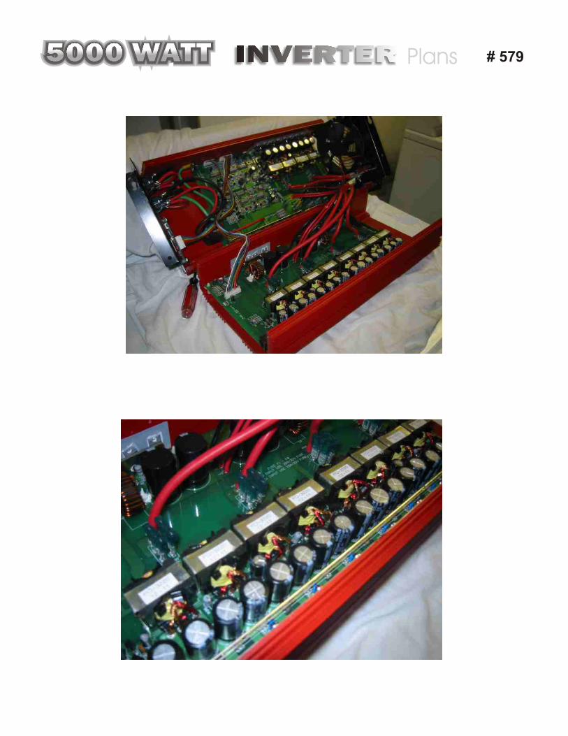
INVERTERINVERTER5000 WATT5000 WATT5000 WATT5000 WATT5000 WATT5000 WATT5000 WATT5000 WATT5000 WATT5000 WATT5000 WATT Plans # 579

# 579

# 579
Fuse Box for 12 vdc line