Embed Size (px)
Citation preview


ABU DHABI
OIL REFINING COMPANY
PROJECT PROCEDURE
INSTALLATION PROCEDURE FOR
ROTATING EQUIPMENT
DOC. NO. : 5578-E1-EPC-PC-091
RUWAIS REFINERY
EXPANSION PROJECT
EPC WORKS
PROJECT NO.: 09-5578-E-1
Rev. 0
SK ENGINEERING & CONSTRUCTION CO., LTD. Page 2/22
This page is a record of all revisions of this document. All previous issues are hereby superseded
and are to be destroyed.
REV DATE DESCRIPTION PRED CHKD REVD
REVD
(PQAM)
APPRD COMPANY
0 20/07/2010 For Construction H.K.PARK M.H. CHOI H.S. KIM Y.S. KIM Y.C KIM
A 18/05/2010 For Information H.K.PARK M.H. CHOI H.S. KIM Y.S. KIM Y.C KIM
SIGNED (Initials)
NOTES;
Revision(s) after Rev. A issue, will be denoted as follows ;
(a) By a vertical line in the right-hand margin against the revised text.
(b) By a triangle symbol for graphics, the revision number being denoted within the symbol.
Revision symbols are positioned adjacent to the revision.
(c) PRED=Prepared by, CHKD=Checked by, REVD = Reviewed by, APPR`D = Approved by
ABU DHABI
OIL REFINING COMPANY
PROJECT PROCEDURE
INSTALLATION PROCEDURE FOR
ROTATING EQUIPMENT
DOC. NO. : 5578-E1-EPC-PC-091
RUWAIS REFINERY
EXPANSION PROJECT
EPC WORKS
PROJECT NO.: 09-5578-E-1
Rev. 0
SK ENGINEERING & CONSTRUCTION CO., LTD. Page 3/22
REVISION LOG
REV.
NO. REV. DATE
REVISED
PAGE REVISION DESCRIPTION
0 20/07/2010 2 Revised due to change of document class from 1 to 3
0 20/07/2010 6(3) Incorporated COMPANY Comments(Ref. No T-PASH/5578-E1/1.5.5/2439)
0 20/07/2010 7(4.1.14) Incorporated COMPANY Comments(Ref. No T-PASH/5578-E1/1.5.5/2439)
0 20/07/2010 8(4.1) Incorporated COMPANY Comments(Ref. No T-PASH/5578-E1/1.5.5/2439)
0 20/07/2010 N/A Issued for Construction at REV. 0

ABU DHABI
OIL REFINING COMPANY
PROJECT PROCEDURE
INSTALLATION PROCEDURE FOR
ROTATING EQUIPMENT
DOC. NO. : 5578-E1-EPC-PC-091
RUWAIS REFINERY
EXPANSION PROJECT
EPC WORKS
PROJECT NO.: 09-5578-E-1
Rev. 0
SK ENGINEERING & CONSTRUCTION CO., LTD. Page 4/22
TABLE OF CONTENTS
1. PURPOSE-----------------------------------------------------------------------------------------5
2. SCOPE---------------------------------------------------------------------------------------------5
3. CODES AND STANDARD--------------------------------------------------------------------5
4. REFERENCE AND DOCUMENTS--------------------------------------------------------7
5. REPONSIBILITIES----------------------------------------------------------------------------8
6. GENARAL---------------------------------------------------------------------------------------8
7. PREPARATION FOR INSTALLATION-------------------------------------------------9
8. INSTALLATION------------------------------------------------------------------------------13
9. LEVELING OF EQUIPMENT-------------------------------------------------------------13
10. GROUTING------------------------------------------------------------------------------------15
11. ALIGNMENT OF EQUIPMENT---------------------------------------------------------17
12. INSPECTION AND PREPARATION BEFORE TEST OPERATION ----------20
13. INSPECTION AFTER TEST OPERATION--------------------------------------------21
14. INSPECTION ---------------------------------------------------------------------------------22

ABU DHABI
OIL REFINING COMPANY
PROJECT PROCEDURE
INSTALLATION PROCEDURE FOR
ROTATING EQUIPMENT
DOC. NO. : 5578-E1-EPC-PC-091
RUWAIS REFINERY
EXPANSION PROJECT
EPC WORKS
PROJECT NO.: 09-5578-E-1
Rev. 0
SK ENGINEERING & CONSTRUCTION CO., LTD. Page 5/22
1. PURPOSE
The purpose of this procedure is to establish the methods for the field installation of
rotating equipment at Ruwais Refinery Expansion Project.
2. SCOPE
This procedure describes the requirements for installation, leveling, alignment work of
pumps, compressors including their drivers and auxiliary equipment and other rotating
equipment.
This procedure describes only general requirement for installation, so the manufacturer’s
installation manuals/instructions shall also be applied for execution of installation.
3. CODES AND STANDARDS
The latest editions of codes and standards listed below shall be considered as integral
parts of this procedure. If the additional codes and standards to the below is stipulated
and referenced in the attached specifications, data sheets and drawings, those also shall
be considered as integral parts of this procedure.
- ASTM & ASME Section II : Materials
- ASME Section IX : Welding and brazing qualification
- ASME Section V : Nondestructive examination
- ASME B16.5/ 16.47 : Steel pipe flanges and flanged fittings
- ASME B31.3 : Process piping
- AWS : American welding society
- NACE MR0103 : Material resistance to sulfide stress cracking
corrosive petroleum refining environment
- ASME Section VIII, Div.1 : Pressure vessels (2007 edition/latest)

ABU DHABI
OIL REFINING COMPANY
PROJECT PROCEDURE
INSTALLATION PROCEDURE FOR
ROTATING EQUIPMENT
DOC. NO. : 5578-E1-EPC-PC-091
RUWAIS REFINERY
EXPANSION PROJECT
EPC WORKS
PROJECT NO.: 09-5578-E-1
Rev. 0
SK ENGINEERING & CONSTRUCTION CO., LTD. Page 6/22
- API 610, 10th
Edition : Centrifugal pumps
- API 682 : Shaft sealing system
- API 550 : Manual on installation of refinery
Instruments and control system
- API 554 : Process instrumentation and control
- API 611 : General purpose steam turbines
- API 613 : Special purpose gear units
- API 614 : Lubrication, shaft sealing, and control
oil system
- API 617 Chapter 1 & 2 : Centrifugal compressors
- API 618 : Reciprocating compressors
- API 661 : Air cooled heat exchanger
- API 671 : Special purpose coupling
- API 673 : Centrifugal fans
- API 670 : Vibration, axial position, bearing
temperature monitoring system
- API 674 : Positive displacement pumps –
reciprocating
- API 675 : Positive displacement pumps –
controlled volume
- API 676 : Positive displacement pumps –
rotary
- IEEE : Institute of electrical and electronics
engineering
- IEC : Electrical apparatus

ABU DHABI
OIL REFINING COMPANY
PROJECT PROCEDURE
INSTALLATION PROCEDURE FOR
ROTATING EQUIPMENT
DOC. NO. : 5578-E1-EPC-PC-091
RUWAIS REFINERY
EXPANSION PROJECT
EPC WORKS
PROJECT NO.: 09-5578-E-1
Rev. 0
SK ENGINEERING & CONSTRUCTION CO., LTD. Page 7/22
- IP15 : Institute of petroleum model code of
safe practice
- CENELEC/ATEX 100a : Explosion protection
- EEMUA 140 : Noise procedure specification
4. REFERENCE DOCUMENTS
4.1 Project Specifications
1) 5578-SP-MD-001 Pressure vessels – general
2) 5578-SP-MU-001 General equipment requirement
3) 5578-SP-MU-002 Preservation and export packing
4) 5578-SP-MU-004 Lubrication requirements
5) 5578-SP-MU-005 Maintenance philosophy
6) 5578-SP-MU-006 Rotating equipment – minimum general requirement
7) 5578-SP-MU-007 Rotating equipment – system integration
8) 5578-SP-MU-008 Plant noise control
9) 5578-SP-MU-009 Equipment noise control
10) 5578-SP-MN-004 Cold & acoustic insulation of piping & equipment
11) 5578-SP-MA-001 Oil mist lubrication system
12) 5578-SP-MG-001 Centrifugal pump(amendments/supplement to API 610 10th
edition)
13) 5578-SP-MG-002 Reciprocating positive displacement pumps
(amendments/supplement to API 674)
14) 5578-SP-MG-003 Centrifugal pumps for general service(Non API )
15) 5578-SP-MG-004 Positive displacement rotary pumps(API 676)
16) 5578-SP-MG-005 Positive displacement pump controlled volume(API 675)
17) 5578-SP-MG-006 Liquid ring vacuum pumps & compressor
(amendments/supplement to API 681)
18) 5578-SP-MK-001 Axial & centrifugal compressor
(amendments/supplement to API 617)
19) 5578-SP-MK-002 Reciprocating compressor (amendments/supplement to API 618)
20) 5578-SP-MK-003 Centrifugal fans (amendments/supplement to API 673)

ABU DHABI
OIL REFINING COMPANY
PROJECT PROCEDURE
INSTALLATION PROCEDURE FOR
ROTATING EQUIPMENT
DOC. NO. : 5578-E1-EPC-PC-091
RUWAIS REFINERY
EXPANSION PROJECT
EPC WORKS
PROJECT NO.: 09-5578-E-1
Rev. 0
SK ENGINEERING & CONSTRUCTION CO., LTD. Page 8/22
21) 5578-SP-MP-002 Air cooled heat exchange equipment
22) 5578-SP-MT-002 General purpose steam turbine
(amendments/supplement to API 611)
23) 5578-SP-MM-001 Electric motor cage – induction and synchronous
24) 5578-SP-CU-011 Grouting
25) 5578-E1-SP-MV-002 Special purpose gear units
(amendments/supplement to API STD 613)
4.2 5578-E1-QA-PA-001 Project Quality Plan
4.3 5578-E1-HSE-PA-001 Project HSE Plan
4.4 Applicable CONTRACTOR’s documents
5. RESPONSIBILITIES
5.1 This procedure shall be provided by the CONTRACTOR’s mechanical engineer,
reviewed by the QA/QC department and approved by COMPANY before use.
5.2 The CONTRACTOR’s mechanical engineer is responsible for supervising these
activities required by this procedure.
6. GENERAL
6.1 The installation work shall comply with the requirements specified herein, the relevant
drawings and the requirements of the applicable safety codes or regulations of the
locality. Any conflicts or questions would be found among this specification, the
drawings and the others shall be referred to CONTRACTOR for resolution.
6.2 All work shall be performed under the CONTRACTOR engineer or his authorized
representative.

ABU DHABI
OIL REFINING COMPANY
PROJECT PROCEDURE
INSTALLATION PROCEDURE FOR
ROTATING EQUIPMENT
DOC. NO. : 5578-E1-EPC-PC-091
RUWAIS REFINERY
EXPANSION PROJECT
EPC WORKS
PROJECT NO.: 09-5578-E-1
Rev. 0
SK ENGINEERING & CONSTRUCTION CO., LTD. Page 9/22
6.3 Instruments and tools to be used in leveling and alignment shall satisfy the conditions
shown in the Table 1.
Table 1
7. PREPARATION FOR INSTALLATION
Prior to starting the work, the following shall be conformed to be satisfactory under
witness of the CONTRACTOR engineer. Any defects found shall be referred to be
CONTRACTOR engineer and repaired or improved properly and immediately in
accordance with the instruction of the CONTRACTOR engineer.
7.1 Foundation
7.1.1 Foundation shall be checked before installation for the following items.
Instruments Service Item Size and Accuracy
Leveling
Spirit level made of steel
Length 200mm and longer, sensitivity 2/100mm Length 200mm and longer, sensitivity 5/100mm
Straight edge made of steel Length 1,500mm(Ibeam type)
Length 500mm(Ibeam type)
Alignment
Dial gauge with magnetic base Min. graduation 1/100mm
Thickness gauge made of steel Length of leaf 100-150mm, width of leaf 10-15mm Length of leaf 200-300mm
Taper gauge made of steel Length of leaf 150mm, width of leaf 10-15mm
Right angle rule made of steel Effective length 300mm, width 300mm
Vernier caliper Length 200mm, graduation 5/100mm(inner and outer use)

ABU DHABI
OIL REFINING COMPANY
PROJECT PROCEDURE
INSTALLATION PROCEDURE FOR
ROTATING EQUIPMENT
DOC. NO. : 5578-E1-EPC-PC-091
RUWAIS REFINERY
EXPANSION PROJECT
EPC WORKS
PROJECT NO.: 09-5578-E-1
Rev. 0
SK ENGINEERING & CONSTRUCTION CO., LTD. Page 10/22
1) Curing period of foundation concrete.
2) Dimensions.
3) Positions (center marking) and height (level marking).
4) Disorders in the foundation concrete, such as abnormal concentration of
aggregates, porous state.
5) Size of anchor bolts, and damage or rust of threaded parts.
6) Dimension and cleanliness of anchor boxes, if anchor box type is applied.
7.1.2 Treatment of the surface of the foundation, such as chipping and fitting, shall be
carried out as follows.
1) Foreign matters shall be completely removed.
2) Foundation surface shall be chipped slightly for the part on which the mortar pad
for liner plates is formed.
7.2 Anchor Bolts
7.2.1 The following conditions of the anchor bolts embedded in the foundation shall be
checked against the drawings or with a steel template for the major equipment.
1) Position - Tolerance shall be 1.5mm from the dimension indicated on the related
equipment drawing.
2) Projection - The projection of the bolts above the foundation surface shall be
proper length relative to the final level of the foundation finish.
3) Inclination - There must be no inclination of the bolts which may prevent the
equipment base plate from fitting smoothly.
4) Condition of bolts and nuts - Threaded parts shall be completely coated with
grease or machine oil allowing the nuts is unscrewed smoothly.

ABU DHABI
OIL REFINING COMPANY
PROJECT PROCEDURE
INSTALLATION PROCEDURE FOR
ROTATING EQUIPMENT
DOC. NO. : 5578-E1-EPC-PC-091
RUWAIS REFINERY
EXPANSION PROJECT
EPC WORKS
PROJECT NO.: 09-5578-E-1
Rev. 0
SK ENGINEERING & CONSTRUCTION CO., LTD. Page 11/22
7.2.2 Anchor bolts with pipe sleeves to allow adjustment of the final positioning of the bolt
shall be checked with the following.
1) Position - Anchor bolts shall be accurately located as shown on the related
equipment drawing.
2) Projection - The projection of the bolts above the foundation surface shall be
proper length relative to the final level of the foundation finish.
3) Sleeve - Unless otherwise specified in the Instruction Manual, pipe sleeves shall
be approximately 50mm larger in diameter than anchor bolt.
7.2.3 When anchor holes are used for anchor bolts, the anchor bolts shall be installed in the
anchor hole after the equipment is temporarily placed in the right position.
After the grouted mortar has sufficiently hardened, leveling work shall be provided.
Anchor holes shall be cleaned before temporary installation of the equipment.
7.3 Liners
7.3.1 Liners to be used, in general, shall be made of carbon steel, unless otherwise specified
in the specific instructions by the manufacturer, etc.
7.3.2 Liners shall be arranged so that the load of the equipment is uniformly distributed on
the foundation within allowable load. In general, the liners shall be placed as near as
possible to both side of each anchor bolt.
7.4 Checking of Equipment
7.4.1 Prior to the installation, the following check to the equipment shall be made:

ABU DHABI
OIL REFINING COMPANY
PROJECT PROCEDURE
INSTALLATION PROCEDURE FOR
ROTATING EQUIPMENT
DOC. NO. : 5578-E1-EPC-PC-091
RUWAIS REFINERY
EXPANSION PROJECT
EPC WORKS
PROJECT NO.: 09-5578-E-1
Rev. 0
SK ENGINEERING & CONSTRUCTION CO., LTD. Page 12/22
1) Appearance of equipment, such as damage and rust free condition.
2) The number and appearance of auxiliaries.
3) Size of the anchor bolts and damage and rust of the threaded parts, if anchor box
type is applied.
4) Orientation marking.
5) Marking of center of gravity.
6) Lifting points.
7.4.2 Oil and other foreign matters stuck on the surface of legs, beds, frames, etc, which
will be in contact with the grouting mortar, shall be entirely removed.
7.5 Condition and Protection of Equipment
7.5.1 Unpacking shall be performed under witness of the CONTRACTOR Engineer. All
spare parts and dismantling tools, etc., shall be repacked and returned to the
warehouse as instructed by the CONTRACTOR Engineer. Delicate parts, such as
level oilers, capillary tubes, etc., shall be removed in accordance with the instructions
of the CONTRACTOR Engineer.
The removed parts shall be stored and maintained in the warehouse properly.
7.5.2 After being thoroughly inspected, the equipment shall be transported to the jobsite.
7.5.3 The condition of the machined surfaces shall be checked, and if necessary, the
machined surfaces shall be coated properly with a suitable rust preventative.
7.5.4 Temporary covers on all openings shall be tightened firmly and shall not be removed
during installation until the related pipelines are to be connected thereto.

ABU DHABI
OIL REFINING COMPANY
PROJECT PROCEDURE
INSTALLATION PROCEDURE FOR
ROTATING EQUIPMENT
DOC. NO. : 5578-E1-EPC-PC-091
RUWAIS REFINERY
EXPANSION PROJECT
EPC WORKS
PROJECT NO.: 09-5578-E-1
Rev. 0
SK ENGINEERING & CONSTRUCTION CO., LTD. Page 13/22
7.5.5 The bottom face of the base plate shall be cleaned. When oil, grease, dirt or any loose
particles are found, it shall be washed off by water or other suitable solvents before
installation.
7.5.6 Coupled equipment shall be uncoupled and left uncoupled until the no-load test for the
driver is finished.
Coupling elements with clear identifications shall be stored properly in the warehouse.
8. INSTALLATION
Installation of equipment shall be executed in accordance with this procedure taking
precautions so that the anchor bolts and foundations will not be damaged and the
equipment not distorted.
When anchor holes are used, the curing time of the grout mortar filled in the holes
shall be checked before the starting of the leveling work.
9. LEVELING OF EQUIPMENT
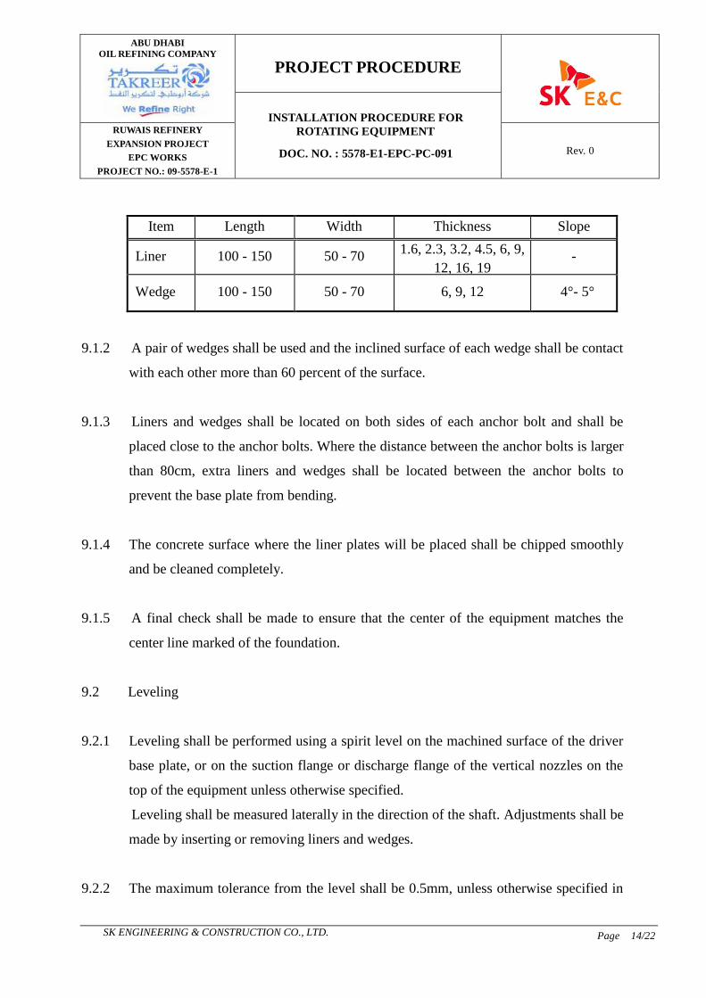
9.1 Liners and Wedges
9.1.1 In general, liners and wedges shall be prepared as indicated in Table 2.
The dimensions may be modified as necessary or each application
Table 2. (unit : mm)
ABU DHABI
OIL REFINING COMPANY
PROJECT PROCEDURE
INSTALLATION PROCEDURE FOR
ROTATING EQUIPMENT
DOC. NO. : 5578-E1-EPC-PC-091
RUWAIS REFINERY
EXPANSION PROJECT
EPC WORKS
PROJECT NO.: 09-5578-E-1
Rev. 0
SK ENGINEERING & CONSTRUCTION CO., LTD. Page 14/22
9.1.2 A pair of wedges shall be used and the inclined surface of each wedge shall be contact
with each other more than 60 percent of the surface.
9.1.3 Liners and wedges shall be located on both sides of each anchor bolt and shall be
placed close to the anchor bolts. Where the distance between the anchor bolts is larger
than 80cm, extra liners and wedges shall be located between the anchor bolts to
prevent the base plate from bending.
9.1.4 The concrete surface where the liner plates will be placed shall be chipped smoothly
and be cleaned completely.
9.1.5 A final check shall be made to ensure that the center of the equipment matches the
center line marked of the foundation.
9.2 Leveling
9.2.1 Leveling shall be performed using a spirit level on the machined surface of the driver
base plate, or on the suction flange or discharge flange of the vertical nozzles on the
top of the equipment unless otherwise specified.
Leveling shall be measured laterally in the direction of the shaft. Adjustments shall be
made by inserting or removing liners and wedges.
9.2.2 The maximum tolerance from the level shall be 0.5mm, unless otherwise specified in
Item Length Width Thickness Slope
Liner 100 - 150 50 - 70 1.6, 2.3, 3.2, 4.5, 6, 9,
12, 16, 19 -
Wedge 100 - 150 50 - 70 6, 9, 12 4°- 5°

ABU DHABI
OIL REFINING COMPANY
PROJECT PROCEDURE
INSTALLATION PROCEDURE FOR
ROTATING EQUIPMENT
DOC. NO. : 5578-E1-EPC-PC-091
RUWAIS REFINERY
EXPANSION PROJECT
EPC WORKS
PROJECT NO.: 09-5578-E-1
Rev. 0
SK ENGINEERING & CONSTRUCTION CO., LTD. Page 15/22
the Instruction Manual.
9.2.3 After leveling is finished the lockouts of the anchor bolts shall be tightened firmly.
9.2.4 After the lockouts of the anchor bolts are tightened firmly, the liners and wedges shall
be tack-welded to each other, and any excess in the liners and wedges shall be cut off
with a gas cutter.
10. GROUTING
10.1 Preparation for Grouting
The top of surface of the foundation shall be wetted thoroughly with fresh water prior
to the grouting work. If pipe sleeves are used for anchor bolts, standing water in the
sleeves shall be removed by a manual air pump, etc.
10.2 Material
10.2.1 Non-shrinking mortar shall be used under the outer frame of the base plate and in the
sleeves. Portland cement may be used in the base plate and in the sleeves to grout the
equipment, unless otherwise specified in the Instruction Manual.
10.2.2 The mixing ratio of non-shrinking mortar, portland cement, and clean fine sand, and
the ratio of water to cement shall be as specified by the non-shrinking mortar
manufacturer.
10.2.3 The mixing ratio of portland cement and clean fine sand shall be 1 : 2 in volume, and
the ratio of water, to cement shall be less than 40 percent in volume, unless otherwise

ABU DHABI
OIL REFINING COMPANY
PROJECT PROCEDURE
INSTALLATION PROCEDURE FOR
ROTATING EQUIPMENT
DOC. NO. : 5578-E1-EPC-PC-091
RUWAIS REFINERY
EXPANSION PROJECT
EPC WORKS
PROJECT NO.: 09-5578-E-1
Rev. 0
SK ENGINEERING & CONSTRUCTION CO., LTD. Page 16/22
specified. Compressive strength of epoxy and non-shrink cementations is 630㎏/㎠
at 7 days.
10.3 Grouting Procedure
10.3.1 Sleeves used for anchor bolts shall be filled with grouting mortar under witness of the
CONTRACTOR engineer after which, grouting for the outer frame of the base plate
shall be done in accordance with par. 4.2.1, unless otherwise specified in the
Instruction Manual.
10.3.2 The base plate shall be grouted as follows :
1) The base plate shall be grouted ram the grout hole.
2) The grout shall cover all wedges and liners.
3) All trapped voids under the base plate shall be vented to allow full penetration of
the grouting mortar.
10.3.3 The surface of the mortar outside the base plate shall be finished smoothly.
10.3.4 All liners and wedges shall not be removed.
10.3.5 Grouting shall be inspected using light hammering to confirm that the mortar is filled
fully in the base plate voids and no cracks shall occur on the hardened surface.
10.3.6 Compressive Strength Test
Grouting shall be sample, cured, and tested for compressive strength in accordance
with ASTM C172, C31 and C39. Compressive test cylinder shall be prepared in one

ABU DHABI
OIL REFINING COMPANY
PROJECT PROCEDURE
INSTALLATION PROCEDURE FOR
ROTATING EQUIPMENT
DOC. NO. : 5578-E1-EPC-PC-091
RUWAIS REFINERY
EXPANSION PROJECT
EPC WORKS
PROJECT NO.: 09-5578-E-1
Rev. 0
SK ENGINEERING & CONSTRUCTION CO., LTD. Page 17/22
set cylinder per each mixing batch for test/and all tests must be carried out in testing
laboratory.
10.4 Epoxy Grouting
10.4.1 Grout for base-mounted or skid-mounted reciprocating machinery or critical
centrifugal/rotary compressors and pumps including drivers shall be epoxy type.
Compliance with minimum requirements of equipment vendors regarding grout
materials and installation is mandatory. Handling and placement of proprietary grouts
shall be in strict accordance with the manufacturer's recommended practice.
10.4.2 Procedure
1) All surfaces must be clean, free from standing water and all loosely adhering
particles. Cement latency must be removed, by mechanical means.
2) Mix with a slow speed electric drill for 1-2 minutes. Then add the aggregate and
continue mixing until a homogeneous mortar is achieved.
3) Application
- When grouting under bearing hates, ensure there is sufficient pressure to
maintain movement of the grout. Air must be allowed to escape.
- For large volumes, apply in more than one layer, ensuring that the previous
layers have hardened and cooled.
4) Clean all tolls and equipment immediately after use with thinner.
11. ALIGNMENT OF EQUIPMENT

ABU DHABI
OIL REFINING COMPANY
PROJECT PROCEDURE
INSTALLATION PROCEDURE FOR
ROTATING EQUIPMENT
DOC. NO. : 5578-E1-EPC-PC-091
RUWAIS REFINERY
EXPANSION PROJECT
EPC WORKS
PROJECT NO.: 09-5578-E-1
Rev. 0
SK ENGINEERING & CONSTRUCTION CO., LTD. Page 18/22
11.1 Initial Alignment
11.1.1 After completion of the grouting and prior to connecting piping, alignment of
equipment shall be performed as follows :
11.1.2 The parallelism of the end surface of the equipment coupling hub and the driver
coupling hub, the clearance between the coupling hubs, and the parallelism of the
center lines of the shafts hall be measured with a dial gauge at the four points at 90
degree intervals, and shall be adjusted by inserting shims under the lug or the saddle
of the driver and/or speed exchanger.
11.1.3 Tolerance of alignment shall be indicated in Table 3. The material of the shims for
alignment shall be of brass or of stainless steel. The size of the shims shall be at least
150mm in width, and 0.03, 0.04, 0.05, 0.1, 0.2, 0.5, 1 and 2mm in thickness, and if
legs or saddles of the equipment are smaller than 150mm in which, the size of the
shims shall be the same as the width of the equipment.
Table 3.
11.2 Alignment after Connecting Piping
After the suction and discharge nozzles are connected to piping, and the
CONTRACTOR engineer informed that all piping work such as installation of
permanent supports, and hydraulic testing, if any, are completed for the connected
Item Tolerance
Parallelism of center lines of shafts 0.05mm
Parallelism of surfaces of coupling hubs 0.1mm(diameter of coupling)

ABU DHABI
OIL REFINING COMPANY
PROJECT PROCEDURE
INSTALLATION PROCEDURE FOR
ROTATING EQUIPMENT
DOC. NO. : 5578-E1-EPC-PC-091
RUWAIS REFINERY
EXPANSION PROJECT
EPC WORKS
PROJECT NO.: 09-5578-E-1
Rev. 0
SK ENGINEERING & CONSTRUCTION CO., LTD. Page 19/22
piping, alignment of the equipment shall be rechecked as follows :
11.2.1 Prior to commencing the final cold alignment, the suction and discharge piping shall
be disconnected and piping alignment such as off center, clearance, and parallelism
between the piping and connection flanges of the equipment nozzles shall be checked
by visual inspection.
11.2.2 When any misalignment is found in the piping during the above inspection, the
information shall be given to the CONTRACTOR engineer.
11.2.3 After the piping alignment check is completed and/or misalignment of piping is
corrected, the suction and discharge piping shall be connected to the equipment
nozzles and the final cold alignment of the equipment shall be checked with a dial
gauge.
11.2.4 Any offset on the alignment of the equipment found as a result of the piping
connections shall be corrected as follows :
1) Offset values of 0.2mm or less shall be adjusted by inserting or removing shims
under the lug or saddle or the driver and/or speed exchangers without correcting
and piping alignment.
2) Offset values exceeding 0.2mm shall be reduced by correcting the suction and/or
discharge piping by burning or re-adjusting the pipe support, and, if necessary,
the suction and/or discharge piping shall be disconnected and be welded again to
correct alignment of the equipment and this welding joint shall be done NDE and
hydraulic testing.

ABU DHABI
OIL REFINING COMPANY
PROJECT PROCEDURE
INSTALLATION PROCEDURE FOR
ROTATING EQUIPMENT
DOC. NO. : 5578-E1-EPC-PC-091
RUWAIS REFINERY
EXPANSION PROJECT
EPC WORKS
PROJECT NO.: 09-5578-E-1
Rev. 0
SK ENGINEERING & CONSTRUCTION CO., LTD. Page 20/22
11.3 Final Check
After completing alignment, the follow shall be ascertained :
11.3.1 By revolving the coupling by the hand or a turning device in the direction of the
arrow mark, the equipment should rotate easily,
11.3.2 The direction or rotating of the driver shall be the same as indicated by the arrow
mark.
11.3.3 After the above and an instrumental check and a no-load test of the drive, the
equipment shall be coupled and be capable of being rotated again easily by the hand
or a turning device. If the equipment has any protection device such as a turbine trip
system, it shall be tested before coupling.
11.3.4 The setting of the coupling guard shall be checked.
12. INSPECTION AND PREPARATION BEFORE TEST OPERATION
12.1 General
Prior to the test operation of the equipment, the following confirmation shall be made
under witness of the CONTRACTOR engineer and vendor.
12.1.1 Chemical cleaning and oil flushing, if specified, have been finished.
12.1.2 The equipment can be rotate easily in the direction of the arrow mark by the hand.
After this inspection, the coupling shall be installed and lubricated properly. The
coupling guard shall be installed firmly.

ABU DHABI
OIL REFINING COMPANY
PROJECT PROCEDURE
INSTALLATION PROCEDURE FOR
ROTATING EQUIPMENT
DOC. NO. : 5578-E1-EPC-PC-091
RUWAIS REFINERY
EXPANSION PROJECT
EPC WORKS
PROJECT NO.: 09-5578-E-1
Rev. 0
SK ENGINEERING & CONSTRUCTION CO., LTD. Page 21/22
12.1.3 All just preventatives, oil, grease, etc., used to protect the equipment during
construction shall be removed using solvents.
12.1.4 The equipment shall be filled with the proper lubricants as instructed in the
Instruction Manual.
12.1.5 All accessories, such as pressure gauges, safety valves etc., shall be installed properly.
12.2 Running Test
After completing the installation work, a running test for each equipment, without
load shall be done under the witness of the Engineer's/Company's representative. If
any unusual sound, vibration of oil leakage in found during the running test, the
operation shall be stopped until the corrective countermeasures are taken.
12.3 Hot Alignment
12.3.1 For equipment operated at high temperatures, if so specified in the Instruction Manual,
the difference in height between the centers of the equipment and driver shall be
checked and adjusted to operate under hot conditions.
12.3.2 The value of the hot alignment shall be clearly indicated on the name plate to be
attached to the coupling guard or shall be clearly painted of the coupling.
13. INSPECTION AFTER TEST OPERATION
13.1 Inspection of Alignment

ABU DHABI
OIL REFINING COMPANY
PROJECT PROCEDURE
INSTALLATION PROCEDURE FOR
ROTATING EQUIPMENT
DOC. NO. : 5578-E1-EPC-PC-091
RUWAIS REFINERY
EXPANSION PROJECT
EPC WORKS
PROJECT NO.: 09-5578-E-1
Rev. 0
SK ENGINEERING & CONSTRUCTION CO., LTD. Page 22/22
13.1.1 The equipment shall be test operated under normal condition. After a steady operation
is attained, the driver shall be stopped and the hot alignment of the coupling shall be
inspected immediately. Any re-adjustment necessary shall be made by inserting or
removing the shims under the saddle of the driver or numbers the pedestal of the
equipment. After adjustment, the equipment shall be operated under normal
condition for several hours and the alignment shall be rechecked in accordance with
para. 11.1 through para.11.3.
13.1.2 The equipment shall be operated only with prior permission of the CONTRACTOR
Engineer.
14. INSPECTION
Inspection shall be made to assure that all the requirement prescribed in para. 7.0
through 13.0 have been done satisfactorily. All inspection and alignment records of
the equipment shall be submitted to Engineers.