Embed Size (px)
Citation preview

Operating instructions - Translation of the original -
English GBR
11.5
.17 Guth Ventiltechnik GmbH
Horstring 16D - 76829 Landau
+49 (0) 6341 5105-0Fax: +49 (0) 6341 5105-85 [email protected]
1
Double seat valve
Type: 567x
EPDM, HNBR
www.sks-online.com www.sks-webshop.com

11.5
.17 Double seat valve Type: 567x
List of contents 2
1. General information................................................................................................................. 31.1 Information for your safety ........................................................................................... 31.2 Marking of security instructions in the operating manual ............................................. 31.3 Designated use ............................................................................................................ 31.4 Personnel ..................................................................................................................... 31.5 Modifications, spare parts, accessories ....................................................................... 31.6 General instructions ..................................................................................................... 3
2. Safety instructions ................................................................................................................... 42.1 Intended use ................................................................................................................ 42.2 General safety instructions .......................................................................................... 42.3 General notes .............................................................................................................. 4
3. Delivery, Transport and Storage ............................................................................................. 53.1 Delivery ........................................................................................................................ 53.2 Transport...................................................................................................................... 53.3 Storage ........................................................................................................................ 5
4. Function and operation............................................................................................................ 64.1 Description of function ................................................................................................. 64.2 Installation instructions................................................................................................. 64.3 Welding guidelines....................................................................................................... 64.4 ATEX-guidelines .......................................................................................................... 64.5 Control system and feedback unit................................................................................ 74.6 Service and maintenance ........................................................................................... 84.7 Technical Data ............................................................................................................. 9
5. Disassembly / Assembly ....................................................................................................... 105.1 Assembly valve insert VE........................................................................................... 105.2 Replacement wear parts ............................................................................................ 115.3 Seal (D4).................................................................................................................... 145.4 Shaft sealing .............................................................................................................. 14
6. Drawings and Dimensions..................................................................................................... 156.1 Double seat valve Type: 567x.................................................................................... 156.2 Valve insert VE DN25 / 1 INCH.................................................................................. 166.3 Valve insert VE DN40 - DN150 / 1½ - 4 INCH........................................................... 176.4 Dimensions ................................................................................................................ 18
7. Sealing- and Spare part list ................................................................................................... 197.1 Spare part list DN25 / OD 1 INCH............................................................................. 197.2 Spare part list DN 40 - 150 / OD 1 - 4 INCH ............................................................. 22
8. Classification ......................................................................................................................... 258.1 Structure of Order Number......................................................................................... 25
9. Declaration of incorporation .................................................................................................. 27
L i s t o f c o n t e n t s
www.sks-online.com www.sks-webshop.com

11.5
.17
1. General information 3
1 . G e n e r a l i n f o r m a t i o n
1.1 Information for your safetyWe are pleased that you have decided for a high-class GUTH product. With correct application and adequatemaintenance, our products provide long time and reliable operation.Before installation and initiation, please carefully read this instruction manual and the security advices containedin it. This guarantees reliable and safe operation of this product and your plant respectively. Please note that anincorrect application of the process components may lead to great material damages and personal injury. In case of damages caused by non observance of this instruction manual, incorrect initiation, handlingor external interference, guarantee and warranty will lapse!Our products are produced, mounted and tested with high diligence. However, if there is still a reason for com-plaint, we will naturally try to give you entire satisfaction within the scope of our warranty. We will be at yourdisposal also after expiration of the warranty. In addition, you will also find all necessary instructions and sparepart data for maintenance in this instruction manual. If you don't want to carry out the maintenance by yourself,our GUTH service team will naturally be at your disposal.
1.2 Marking of security instructions in the operating manualHints are available in the chapter "safety instructions" or directly before the respective operation instruction. Thehints are highlighted with a danger symbol and a signal word. Texts beside these symbols have to be read andadhered to by all means. Please continue with the text and with the handling at the valve only afterwards.
1.3 Designated useThe fitting is designed exclusively for the purposes described below. Using the fitting for purposes other thanthose mentioned is considered contrary to its designated use. GUTH cannot be held liable for any damageresulting from such use. The risk of such misuse lies entirely with the user. The prerequisite for the reliable andsafe operation of the fitting is proper transportation and storage as well as competent installation and assembly.Operating the fitting within the limits of its designated use also involves observing the operating, inspection andmaintenance instructions.
1.4 PersonnelPersonnel entrusted with the operation and maintenance of the tank safety system must have the suitable qual-ification to carry out their tasks. They must be informed about possible dangers and must understand andobserve the safety instructions given in the relevant manual. Only allow qualified personnel to make electricalconnections.
1.5 Modifications, spare parts, accessoriesUnauthorized modifications, additions or conversions which affect the safety of the fitting are not permitted.Safety devices must not be bypassed, removed or made inactive. Only use original spare parts and accessoriesrecommended by the manufacturer.
1.6 General instructionsThe user is obliged to operate the fitting only when it is in good working order. In addition to the instructionsgiven in the operating manual, please observe the relevant accident prevention regulations, generally acceptedsafety regulations, regulations effective in the country of installation, working and safety instructions effective inthe user's plant.
Symbol Signal word Meaning
DANGERImminent danger which will result severe per-sonal injury or death.
WARNINGImminent danger which may result severe per-sonal injury or death.
CAUTIONDangerous situation which may cause slightpersonal injury or material damages.
ATTENTIONAn harmful situation which may result in dam-ages of the product itself or of adjacent vicinity.
NOTICEMarks application hints and other informationwhich is particularly useful.
www.sks-online.com www.sks-webshop.com
11.5
.17 Double seat valve Type: 567x
2. Safety instructions 4
2 . S a f e t y i n s t r u c t i o n s
2 . 1 Intended use
Based upon its functions, the double seat valve is suitable for use in the food and beverages, inpharmaceutical, biotechnological and chemical industries. It is used mainly in combinations withseveral other double seat valves for the purpose of emptying and filling containers with the possi-bility of connecting several pipes to one tank.
2 . 2 General safety instructions
2 . 3 General notes
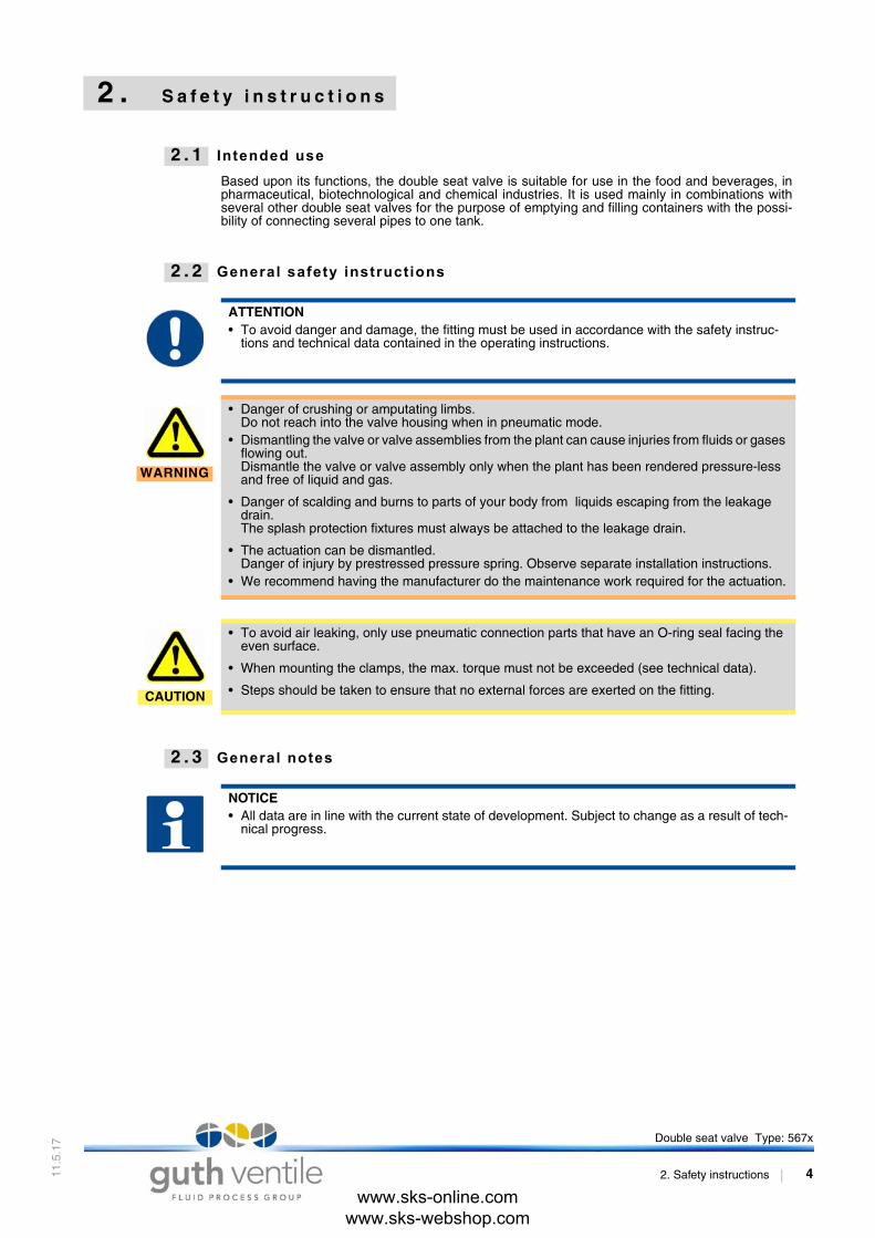
ATTENTION• To avoid danger and damage, the fitting must be used in accordance with the safety instruc-
tions and technical data contained in the operating instructions.
WARNING
• Danger of crushing or amputating limbs. Do not reach into the valve housing when in pneumatic mode.
• Dismantling the valve or valve assemblies from the plant can cause injuries from fluids or gases flowing out.Dismantle the valve or valve assembly only when the plant has been rendered pressure-less and free of liquid and gas.
• Danger of scalding and burns to parts of your body from liquids escaping from the leakage drain.The splash protection fixtures must always be attached to the leakage drain.
• The actuation can be dismantled.Danger of injury by prestressed pressure spring. Observe separate installation instructions.
• We recommend having the manufacturer do the maintenance work required for the actuation.
CAUTION
• To avoid air leaking, only use pneumatic connection parts that have an O-ring seal facing the even surface.
• When mounting the clamps, the max. torque must not be exceeded (see technical data).
• Steps should be taken to ensure that no external forces are exerted on the fitting.
NOTICE• All data are in line with the current state of development. Subject to change as a result of tech-
nical progress.
www.sks-online.com www.sks-webshop.com

11.5
.17 Double seat valve Type: 567x
3. Delivery, Transport and Storage 5
3 . D e l i v e r y , T r a n s p o r t a n d S t o r a g e
3 . 1 Delivery
• Immediately after receipt check the delivery for completeness and transport damages.• Remove the packaging from the product.• Retain packaging material, or expose of according to local regulations.
3 . 2 Transport
3 . 3 Storage
• To avoid damage to seals and bearings, - products up to DN 125 / OD 5 inch should be stored horizontally for maximum 6 months.- products larger than DN 125 / 5 inch, should be stored in the upright position with the actuator
on top.• Don't store any objects on the products.• Protect the products for wetness, dust and dirt.• The product should be stored in a dry and well ventilated room at a constant temperature.
(optimal indoor temperature: 25°C ±5°; indoor humidity data 70% ±5%)• Protect seals, bearings and plastic parts for UV light and ozone.
CAUTION
During the transport the - generally acknowledged rules of technology, - the national accident prevention regulations- and company internal work and safety regulations
must be observed.
ATTENTION• Damage to the product due to improper storage!
- Observe storage instructions.- avoid a prolonged storage.
NOTICE• GUTH recommend regularly checking the product and the prevailing storage conditions during
long storage times.• The following points must be observed, to ensure the optimum function of the sealing elements,
bearings and electronic components.
www.sks-online.com www.sks-webshop.com
11.5
.17
4 . F u n c t i o n a n d o p e r a t i o n
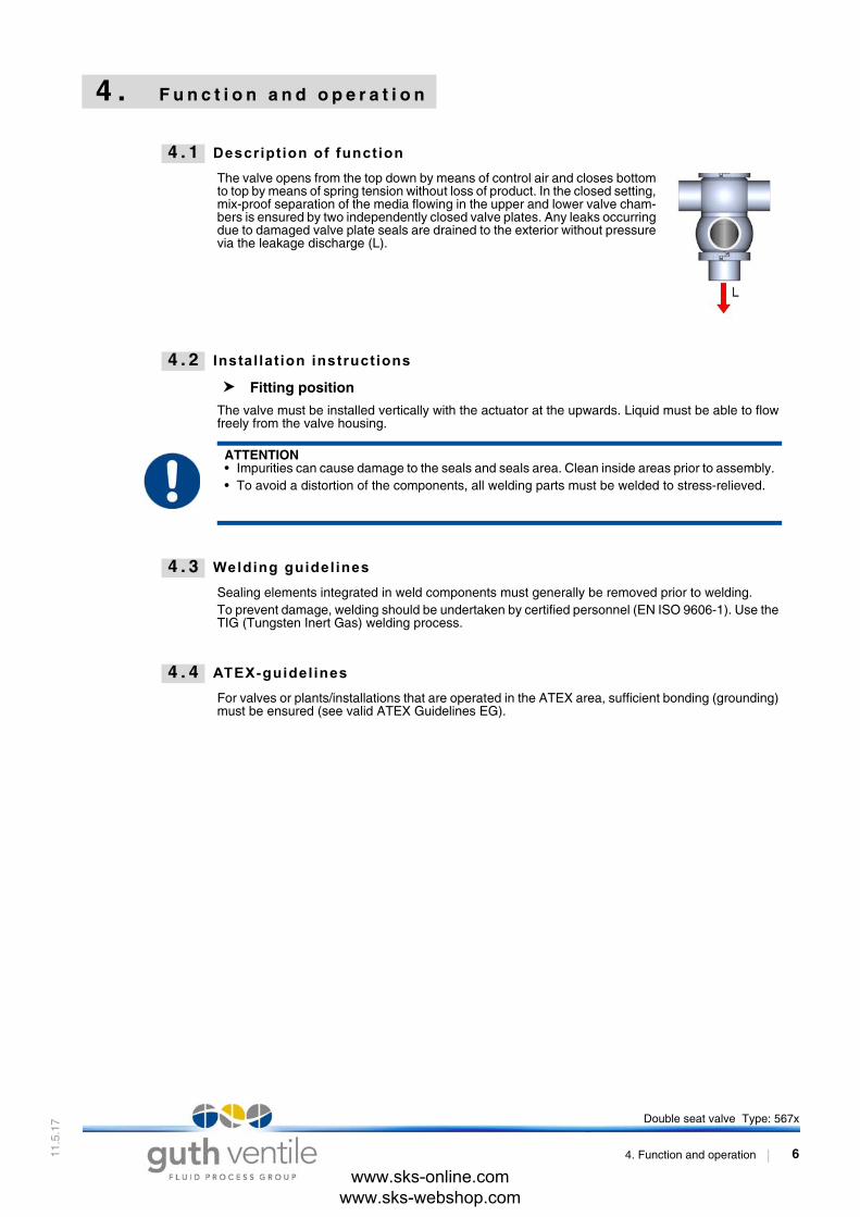
4 . 1 Description of function
The valve opens from the top down by means of control air and closes bottomto top by means of spring tension without loss of product. In the closed setting,mix-proof separation of the media flowing in the upper and lower valve cham-bers is ensured by two independently closed valve plates. Any leaks occurringdue to damaged valve plate seals are drained to the exterior without pressurevia the leakage discharge (L).
4 . 2 Instal lat ion instructions
Fitting position
The valve must be installed vertically with the actuator at the upwards. Liquid must be able to flowfreely from the valve housing.
4 . 3 Welding guidelines
Sealing elements integrated in weld components must generally be removed prior to welding. To prevent damage, welding should be undertaken by certified personnel (EN ISO 9606-1). Use theTIG (Tungsten Inert Gas) welding process.
4 . 4 ATEX-guidelines
For valves or plants/installations that are operated in the ATEX area, sufficient bonding (grounding)must be ensured (see valid ATEX Guidelines EG).
ATTENTION• Impurities can cause damage to the seals and seals area. Clean inside areas prior to assembly.• To avoid a distortion of the components, all welding parts must be welded to stress-relieved.
Double seat valve Type: 567x
4. Function and operation 6
www.sks-online.com www.sks-webshop.com

11.5
.17
4 . 5 Control system and feedback unit
Control head -optional-
Optionally, modular valve control head systems can be installed to the actuatorfor reading and actuating valve positions. The standard version is a closed sys-tem with SPS or ASI-bus switch-on electronics, and integrated 3/2-way solenoidvalves. For tough operating conditions we recommend employing a high-gradesteel cover.
Feedback unit with finger guard -optional-
For the acquisition of the valve positions over inductive initiators (Sensors), afeedback unit is mounted on the actuation. The enquiry takes place over theposition of the piston rod.
Pneumatic valve actuation
Valve functionPneum. control
➟ with integrated (MV) in control unit(fig. 4 - 1 /page 7)
Pneum. control➟ with external (MV)
(fig. 4 - 2 /page 7)
Valve strokevalve “OPEN“
control air feedP ➟ MV1 ➟ P1/LA1
control air feedext.MV1 ➟ LA1
Valve strokevalve “CLOSED“
de-aerationP1/LA1 ➟ MV1 ➟ Rvalve is closing by spring
de-aerationLA1 ➟ ext.MV1
valve is closing by spring
Lower seat lift
AUF = control air feedP ➟ MV2 ➟ P2/LA2
AUF = control air feedext.MV2 ➟ P ➟ LA2
CLOSE = de-aerationP2/LA2 ➟ MV2 ➟ Rvalve is closing by spring
CLOSE = de-aerationLA2 ➟ P ➟ ext.MV2valve is closing by spring
Upper seat lift
AUF = control air feedP ➟ MV3 ➟ P3/LA3
AUF = control air feedext.MV3 ➟ LA3
CLOSE = de-aerationP3/LA3 ➟ MV3 ➟ Rvalve is closing by spring
CLOSE = de-aerationLA3 ➟ ext.MV3
valve is closing by spring
with control unit and solenoid valve pneum. control external
MV = solenoid valve
MV1 = valve stroke
MV2 = lower seat lift
MV3 = upper seat lift
R = de-aeration, sound absorber
P = compressed-air inlet (control unit)
LA = compressed-air inlet (actuation)
S = slide switch - manual control (solenoid valves)
E = proximity switch M12x1
H = feedback unit
Fig. 4 - 1 Fig. 4 - 2
Double seat valve Type: 567x
4. Function and operation 7
www.sks-online.com www.sks-webshop.com
11.5
.17
4 . 6 Service and maintenance
Service
The maintenance intervals depend on the operating conditions "temperature, temperature-inter-vals, medium, cleaning medium, pressure and opening frequency". We recommend replacing theseals every 1 years. The user, however should establish appropriate maintenance intervals accord-ing to the condition of the seals.
Lift actuatorThe actuator is maintenance-free and non-removable.
Cleaning
Cleaning of the housing is performed with the pipe cleaning system. As part of the cleaning pro-gram, the leakage chamber and the drain pipe can be cleaned by cycling the valve discs. The valvedisc shaft is also cleaned when the upper valve disc is cycled.Alternatively, the leakage chamber and the shaft of the upper valve disc can be cleaned by meansof the external rinsing connection (Sp). For cleaning the shaft, the upper valve disc has to be lifted.
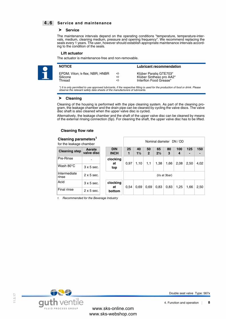
Cleaning flow rate
NOTICE Lubricant recommendation
EPDM; Viton; k-flex; NBR; HNBRSiliconeThread
Klüber Paraliq GTE703*Klüber Sintheso pro AA2*Interflon Food Grease*
*) It is only permitted to use approved lubricants, if the respective fitting is used for the production of food or drink. Please observe the relevant safety data sheets of the manufacturers of lubricants.
Cleaning parameters1
for the leakage chamber
1. Recommended for the Beverage Industry
Nominal diameter DN / OD
Cleaning step Aerate valve disc
DININCH
251
401½
502
652½
803
1004
125-
150-
Pre-Rinse - clockingat
top0,97 1,10 1,1 1,38 1,66 2,08 2,50 4,02
Wash 80°C 3 x 5 sec.
Intermediaterinse 2 x 5 sec. (l/s at 3bar)
Acid 3 x 5 sec. clockingat
bottom0,54 0,69 0,69 0,83 0,83 1,25 1,66 2,50
Final rinse 2 x 5 sec.
Double seat valve Type: 567x
4. Function and operation 8
www.sks-online.com www.sks-webshop.com

11.5
.17
4 . 7 Technical Data
Model: Double seat valve
Valve size: DIN: DN25 - DN150INCH: DN1 - DN4
Connection: Welding end DIN EN 10357
Temperature range: • Ambient temperature:• Product temperature:• Sterilization temperature:
(short time 30min)
+4° - +45°C+0° - +95°C medium dependentEPDM +140°C HNBR +110°C
Operations pressure: DIN: DN25 - 100 = max. 10 barDN125 - 150 = max. 6 bar
INCH: OD1 - OD4 = max. 10 bar
Pressure resistance: 40 bar
Leak rate: A (DIN EN 12268-1)
Control air pressure: 5,5 - 8,0 bar
Quality of control air: ISO 8573-1 : 2001 quality class 3
Material: in product contact not in product contact
Stainless steel: 1.4404 / AISI316L 1.4301 / AISI304
Surfaces: RA 0,8µm e-pol. metallic bright, e-pol.
Seals: EPDM (FDA)HNBR (FDA)
NBR
Nominal diameter DN / OD
Tightening moment:Torque in Nm
DININCH
251
401½
502
652½
803
1004
125-
150-
Retaining clamp: 15 15 15 25 25 55 65 65
KV-value (m³/h): Nominal diameter DN / OD
Direction of flow: DININCH
251
401½
502
652½
803
1004
125-
150-
transition-flow at top 26 50 95 150 240 380 580 940
transition-flow at bottom 26 55 100 155 250 390 590 940
from bottom to top 16 26 45 72 98 155 245 370
from top to bottom 16 24 43 67 93 150 240 330
Double seat valve Type: 567x
4. Function and operation 9
www.sks-online.com www.sks-webshop.com
11.5
.17
5 . D i s a s s e m b l y / A s s e m b l y
Mounting tools
Mounting tool sets: DN40 - DN65DN80 - DN100DN125 - DN150
5670 065 100-0005670 100 100-0005670 150 100-000
M1 Socket DN40 - DN65DN80 - DN150
5620 065 131-1305620 100 131-130
M2 Eccentric socket DN40 - DN65DN80 - DN150
5620 065 134-1305620 100 134-130
M3 Eccentric ring DN40/50DN65DN80DN100DN125DN150
5620 050 025-0205620 065 025-0205620 080 025-0205620 100 025-0205620 125 025-0205620 150 025-020
M4 Joint -pin wrench DN40 - DN65DN80 - DN150
5620 065 015-0005620 150 015-000
M5 Socket+ guide bush (POM) and O-Ring
DN40 - DN65DN80 - DN100DN125 - DN150
5670 080 105-0005670 100 105-0005670 150 105-000
M6 Mounting plate DN40 - DN65DN80 - DN100DN125 - DN150
5620 065 121-0205620 100 121-0205620 150 121-020
NOTICE• All threaded joint have right-hand thread.• Unscrew and remove control air, steam resp. cleaning lines and electrical lines, complete feedback unit
or control head.
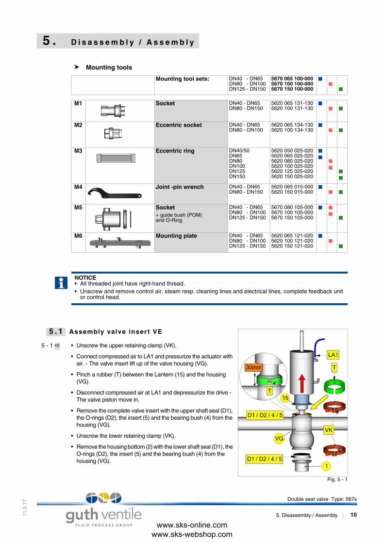
5 . 1 Assembly valve insert VE
5 - 1 • Unscrew the upper retaining clamp (VK).
• Connect compressed air to LA1 and pressurize the actuator with air. - The valve insert lift up of the valve housing (VG).
• Pinch a rubber (T) between the Lantern (15) and the housing (VG).
• Disconnect compressed air at LA1 and depressurize the drive - The valve piston move in.
• Remove the complete valve insert with the upper shaft seal (D1), the O-rings (D2), the insert (5) and the bearing bush (4) from the housing (VG).
• Unscrew the lower retaining clamp (VK).
• Remove the housing bottom (2) with the lower shaft seal (D1), the O-rings (D2), the insert (5) and the bearing bush (4) from the housing (VG).
www.sks-online.com www.sks-webshop.com
Fig. 5 - 1
Double seat valve Type: 567x
5. Disassembly / Assembly 10
11.5
.17
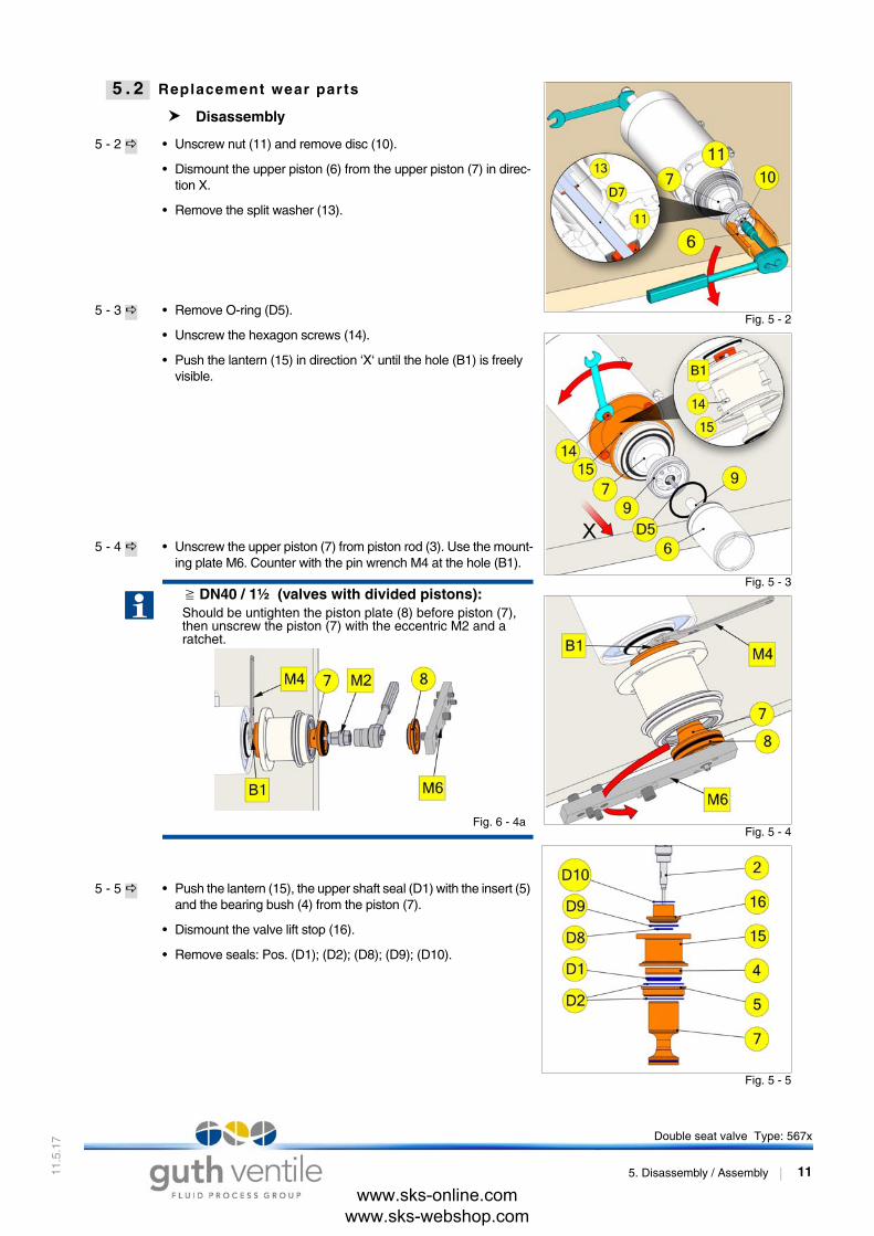
5 . 2 Replacement wear par ts
Disassembly
5 - 2 • Unscrew nut (11) and remove disc (10).
• Dismount the upper piston (6) from the upper piston (7) in direc-tion X.
• Remove the split washer (13).
5 - 3 • Remove O-ring (D5).
• Unscrew the hexagon screws (14).
• Push the lantern (15) in direction ‘X‘ until the hole (B1) is freely visible.
5 - 4 • Unscrew the upper piston (7) from piston rod (3). Use the mount-ing plate M6. Counter with the pin wrench M4 at the hole (B1).
5 - 5 • Push the lantern (15), the upper shaft seal (D1) with the insert (5) and the bearing bush (4) from the piston (7).
• Dismount the valve lift stop (16).
• Remove seals: Pos. (D1); (D2); (D8); (D9); (D10).
DN40 / 1½ (valves with divided pistons):Should be untighten the piston plate (8) before piston (7), then unscrew the piston (7) with the eccentric M2 and a ratchet.
Fig. 6 - 4a
www.sks-online.com www.sks-webshop.com
Fig. 5 - 2
Fig. 5 - 3
Fig. 5 - 4
Fig. 5 - 5
Double seat valve Type: 567x
5. Disassembly / Assembly 11

11.5
.17
Assembly seal (D4)
5 - 6
5 - 7 DN25 Dismount - (D4) O-ring version
• Puncture the O-ring (D4) with a needle and remove them from the groove of piston (6) and (7).
5 - 8 DN40 - DN150 Dismount O-ring / seal (D4)
• Clamp the mounting plate M6 into the vice.
• Put the piston (8) resp. (7) in the fittingly pins. (see Fig. 5 - 8)
• Unscrew the piston (6) from piston plate (9) with the socket M5 and the mating reducing bush.
• Unscrew the piston (7) from piston plate (8) with the socket M1.
5 - 9 • Remove seals resp. O-rings (D4).
ModelSeal (D4)
Piston (6) and (7)
Pair of pistons upper: (7) + (8)Pair of pistons lower: (6) + (9)
DN 25OD 1“
DN 40 - 125OD 1½“ - 5“
DN 150OD 6“
Piston undivided1
1. According their construction from valve size DN 25/1“, the pistons (6) and (7) are not divided.
Pistondivided
Pistondivided
O-ring X X X
Seal(with backup ring) - X -
www.sks-online.com www.sks-webshop.com
Fig. 5 - 6
Fig. 5 - 7
Fig. 5 - 8
Fig. 5 - 9
Double seat valve Type: 567x
5. Disassembly / Assembly 12

11.5
.17
Assembly
Assemble in reverse order.Thoroughly clean and slightly lubricate mounting areas and run-ning surfaces.
Mounting O-ring (D4) for undivided piston
5 - 10 • Slide the O-ring onto the groove.
• Resolve contingently twistings of the seal with a rod between seal and Groove.
• Alternately press and roll the seal into the groove with round body.
Mounting seal (D4) for divided piston Pair of piston upper = Piston (7) and piston plate (8) Pair of piston lower = Piston (6) and piston plate (9)
5 - 11 • Screw together the pair of piston (7) / (8) and (6) / (9) without the seal (D4) to the metal limit stop by hand.
• Make a coloured mark at the piston surfaces.
• After then, unscrew the pairs of piston (7) / (8) and (6) / (9) again.
5 - 12 • Push the seal (D4) onto the pistons.
• Screw together the pair of piston by hand again.
• Clamp the mounting plate M6 into the vice.
• Fix the lower pair of piston (6) / (9) with the piston plate (9) in the mounting plate M6.
• Position the eccentric ring (M3) on seal (D4).
• Screw up the piston (6) to the final limit mark. Use the socket M5 and a ratchet.
5 - 13 • Clamp the socket M1 into the vice at the hexagon flat.
• Fix the upper pair of piston (7) / (8) with the piston (7) of the socket M1.
• Position the eccentric ring (M3) on seal (D4).
• Screw up the piston plate (8) to the final limit mark. Use the mounting plate M6.
NOTICE• Fit valve insert carefully into the casing. When fitting the
valve insert and running surfaces onto the piston, do not damage.
• Always replace the hexagon lock nut (11) by a new one after unscrewing.
• Check valve functions by manually activating the 3/2-way solenoid valves after assembly!
www.sks-online.com www.sks-webshop.com
Fig. 5 - 10
Fig. 5 - 11
Fig. 5 - 12
Fig. 5 - 13
Double seat valve Type: 567x
5. Disassembly / Assembly 13

11.5
.17
5 . 8 Seal (D4)
5 . 9 Shaft sealing
ModelSeal (D4)
Piston (6) and (7)
Pair of pistons upper: (7) + (8)Pair of pistons lower: (6) + (9)
DN 25OD 1“
DN 40 - 125OD 1½“ - 5“
DN 150OD 6“
Piston undivided1
1. According their construction from valve size DN 25/1“, the pistons (6) and (7) are not divided.
Piston divided Piston divided
a) O-ring EPDM X X2
2. till 05/2016 thereafter seal (D4)c
X
b) O-ring HNBR X X3
3. till 05/2016 thereafter seal (D4)d
X
c) Seal EPDM (with backup ring)
- X -
d) Seal HNBR (with backup ring)
- X -
O-ring - model (a,b) Seal - model (c,d)
D4 = O-ring D4 = Seal
D4-1 = Seal jacket
D4-2 = Backup ring
Shaft sealing
D1 = Shaft seal
D2 = O-rings
4 = Bearing bush
5 = Housing insert
Double seat valve Type: 567x
5. Disassembly / Assembly 14
www.sks-online.com www.sks-webshop.com
11.5
.17
6 . D r a w i n g s a n d D i m e n s i o n s
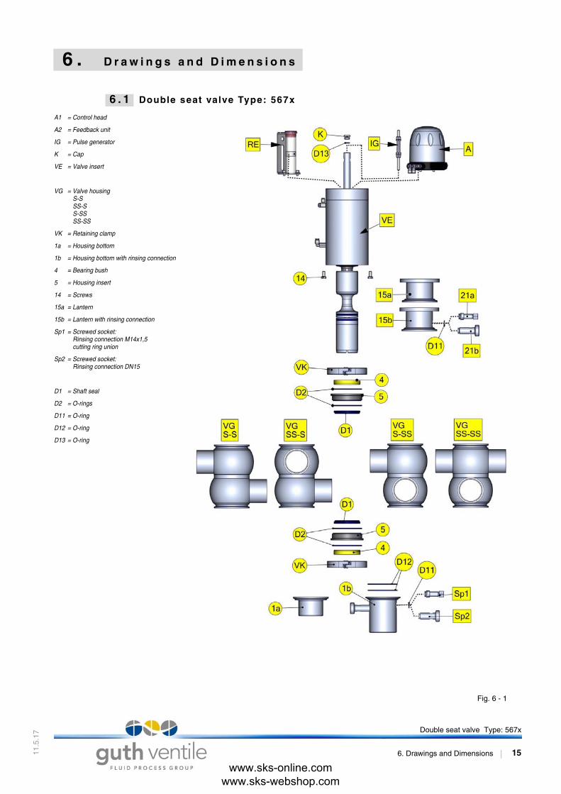
6 . 1 Double seat valve Type: 567x
A1 = Control head
A2 = Feedback unit
IG = Pulse generator
K = Cap
VE = Valve insert
VG = Valve housingS-SSS-SS-SSSS-SS
VK = Retaining clamp
1a = Housing bottom
1b = Housing bottom with rinsing connection
4 = Bearing bush
5 = Housing insert
14 = Screws
15a = Lantern
15b = Lantern with rinsing connection
Sp1 = Screwed socket: Rinsing connection M14x1,5 cutting ring union
Sp2 = Screwed socket:Rinsing connection DN15
D1 = Shaft seal
D2 = O-rings
D11 = O-ring
D12 = O-ring
D13 = O-ring
Fig. 6 - 1
Double seat valve Type: 567x
6. Drawings and Dimensions 15
www.sks-online.com www.sks-webshop.com
11.5
.17
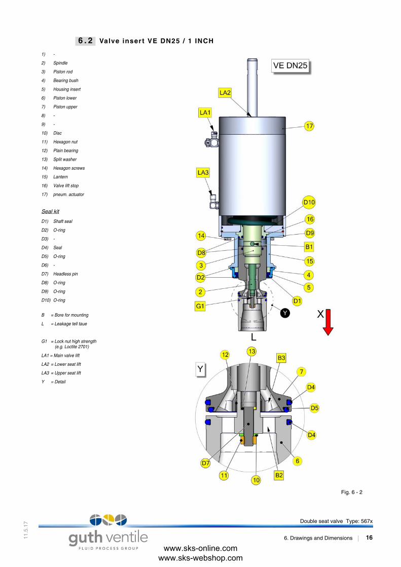
6 . 2 Valve inser t VE DN25 / 1 INCH
1) -
2) Spindle
3) Piston rod
4) Bearing bush
5) Housing insert
6) Piston lower
7) Piston upper
8) -
9) -
10) Disc
11) Hexagon nut
12) Plain bearing
13) Split washer
14) Hexagon screws
15) Lantern
16) Valve lift stop
17) pneum. actuator
Seal kit
D1) Shaft seal
D2) O-ring
D3) -
D4) Seal
D5) O-ring
D6) -
D7) Headless pin
D8) O-ring
D9) O-ring
D10) O-ring
B = Bore for mounting
L = Leakage tell taue
G1 = Lock nut high strength (e.g. Loctite 2701)
LA1 = Main valve lift
LA2 = Lower seat lift
LA3 = Upper seat lift
Y = Detail
Fig. 6 - 2
Double seat valve Type: 567x
6. Drawings and Dimensions 16
www.sks-online.com www.sks-webshop.com

11.5
.17
6 . 3 Valve inser t VE DN40 - DN150 / 1½ - 4 INCH
1) -
2) Spindle
3) Piston rod
4) Bearing bush
5) Housing insert
6) Piston lower
7) Piston upper
8) Piston plate upper
9) Piston plate lower
10) Disc
11) Hexagon nut
12) Plain bearing
13) Split washer
14) Hexagon screws
15) Lantern
16) Valve lift stop
17) pneum. actuator
Seal kit
D1) Shaft seal
D2) O-ring
D3) O-ring
D4) seal
D5) O-ring
D6) O-ring
D7) Headless pin
D8) O-ring
D9) O-ring
D10) O-ring
B = Bore for mounting
E = Nut
L = Leakage tell taue
G1 = Lock nut high strength (e.g. Loctite 2701)
LA1 = Main valve lift
LA2 = Lower seat lift
LA3 = Upper seat lift
Y = Detail
Fig. 6 - 3
Double seat valve Type: 567x
6. Drawings and Dimensions 17
www.sks-online.com www.sks-webshop.com
11.5
.17
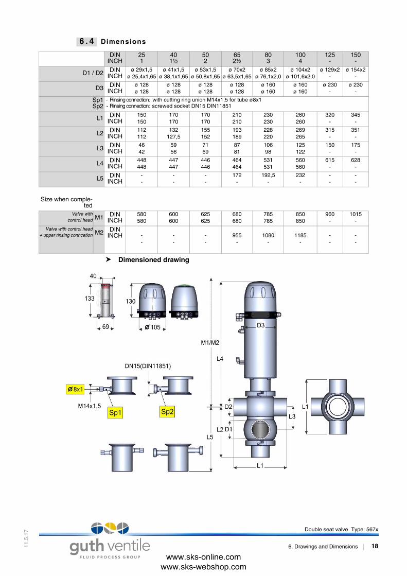
6 . 4 Dimensions
Dimensioned drawing
Fig. 6 - 4
DININCH
251
401½
502
652½
803
1004
125-
150-
D1 / D2 DININCH
ø 29x1,5ø 25,4x1,65
ø 41x1,5ø 38,1x1,65
ø 53x1,5ø 50,8x1,65
ø 70x2 ø 63,5x1,65
ø 85x2ø 76,1x2,0
ø 104x2ø 101,6x2,0
ø 129x2-
ø 154x2-
D3 DININCH
ø 128ø 128
ø 128ø 128
ø 128ø 128
ø 128ø 128
ø 160ø 160
ø 160ø 160
ø 230-
ø 230-
Sp1Sp2
- Rinsing connection: with cutting ring union M14x1,5 for tube ø8x1 - Rinsing connection: screwed socket DN15 DIN11851
L1 DININCH
150150
170170
170170
210210
230230
260260
320-
345-
L2 DININCH
112112
132127,5
155152
193189
228220
269265
315-
351-
L3 DININCH
4642
5956
7169
8781
10698
125122
150-
175-
L4 DININCH
448448
447447
446446
464464
531531
560560
615-
628-
L5 DININCH
--
--
--
172-
192,5-
232-
--
--
Size when comple-ted
Valve withcontrol head M1 DIN
INCH580580
600600
625625
680680
785785
850850
960-
1015-
Valve with control head+ upper rinsing conncetion M2 DIN
INCH --
--
--
955-
1080-
1185-
--
--
Double seat valve Type: 567x
6. Drawings and Dimensions 18
www.sks-online.com www.sks-webshop.com
11.5
.17
7 . S e a l i n g - a n d S p a r e p a r t l i s t
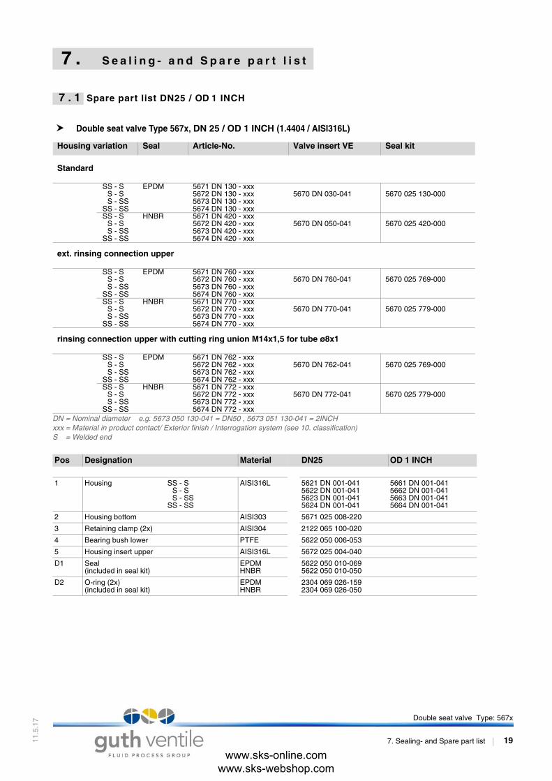
7 . 1 Spare part list DN25 / OD 1 INCH
Double seat valve Type 567x, DN 25 / OD 1 INCH (1.4404 / AISI316L)
Housing variation Seal Article-No. Valve insert VE Seal kit
Standard
SS - S EPDM 5671 DN 130 - xxx5670 DN 030-041 5670 025 130-000S - S 5672 DN 130 - xxx
S - SS 5673 DN 130 - xxxSS - SS 5674 DN 130 - xxxSS - S HNBR 5671 DN 420 - xxx
5670 DN 050-041 5670 025 420-000S - S 5672 DN 420 - xxxS - SS 5673 DN 420 - xxx
SS - SS 5674 DN 420 - xxx
ext. rinsing connection upper
SS - S EPDM 5671 DN 760 - xxx5670 DN 760-041 5670 025 769-000S - S 5672 DN 760 - xxx
S - SS 5673 DN 760 - xxxSS - SS 5674 DN 760 - xxxSS - S HNBR 5671 DN 770 - xxx
5670 DN 770-041 5670 025 779-000S - S 5672 DN 770 - xxxS - SS 5673 DN 770 - xxx
SS - SS 5674 DN 770 - xxx
rinsing connection upper with cutting ring union M14x1,5 for tube ø8x1
SS - S EPDM 5671 DN 762 - xxx5670 DN 762-041 5670 025 769-000S - S 5672 DN 762 - xxx
S - SS 5673 DN 762 - xxxSS - SS 5674 DN 762 - xxxSS - S HNBR 5671 DN 772 - xxx
5670 DN 772-041 5670 025 779-000S - S 5672 DN 772 - xxxS - SS 5673 DN 772 - xxx
SS - SS 5674 DN 772 - xxxDN = Nominal diameter e.g. 5673 050 130-041 = DN50 , 5673 051 130-041 = 2INCHxxx = Material in product contact/ Exterior finish / Interrogation system (see 10. classification)S = Welded end
Pos Designation Material DN25 OD 1 INCH
1 Housing SS - SS - SS - SS
SS - SS
AISI316L 5621 DN 001-0415622 DN 001-0415623 DN 001-0415624 DN 001-041
5661 DN 001-041 5662 DN 001-0415663 DN 001-0415664 DN 001-041
2 Housing bottom AISI303 5671 025 008-220
3 Retaining clamp (2x) AISI304 2122 065 100-020
4 Bearing bush lower PTFE 5622 050 006-053
5 Housing insert upper AISI316L 5672 025 004-040
D1 Seal(included in seal kit)
EPDMHNBR
5622 050 010-0695622 050 010-050
D2 O-ring (2x)(included in seal kit)
EPDMHNBR
2304 069 026-1592304 069 026-050
Double seat valve Type: 567x
7. Sealing- and Spare part list 19
www.sks-online.com www.sks-webshop.com

11.5
.17
Spare part list - Valve insert VE Type 5670, DN 25 / OD 1 INCH
Pos Designation Material DN25 OD 1 INCH
VE Valve insert (a) Standard
EPDMHNBR
5670 025 030-0415670 025 050-041
5670 026 030-0415670 026 050-041
VE Valve insert (b)ext. rinsing connection upper
EPDMHNBR
5670 025 760-0415670 025 770-041
5670 026 760-0415670 026 770-041
VE Valve insert (c)rinsing connection with cutting ring union M14x1,5 for tube ø8x1
EPDMHNBR
5670 025 762-0415670 025 772-041
5670 026 762-0415670 026 772-041
4 Bearing bush upper PTFE 5622 050 006-053
5 Housing insert upper AISI316L 5672 025 004-040
6 Piston lower AISI316L 5671 025 005-040
7 Piston uper AISI316L 5622 025 003-040
8 - - -
9 - - -
10 Disc AISI304 8071 064 001-020
11 Hexagon nut AISI304 8113 006 000-020
12 Plain bearing XMS 8050 015 007-156
13 Split washer AISI304 8140 006 001-020
14 Hexagon screw AISI304 8106 008 016-020
15 Lantern Valve insert (a)Lantern compl. - Valve insert (b)Lantern compl. - Valve insert (c)
AISI304AISI304AISI304
5624 040 008-0215624 040 515-0215624 040 517-021
16 Valve lift stop AISI303 5622 025 009-220
17 Pneum. actuator AISI304 5620 065 000-021
D13 O-ring NBR 2304 012 020-055
K Cap AISI303 5622 100 071-220
Sp1 Screwed socket: Rinsing connection M14x1,5 cutting ring union
5624 065 506-220
Sp2 Screwed socket: Rinsing connection DN15 AISI303 5624 065 514-020
LA1 One-way restricter - 8218 001 020-000
LA3 Rapid action hose coupling - 8217 000 004-000
Double seat valve Type: 567x
7. Sealing- and Spare part list 20
www.sks-online.com www.sks-webshop.com

11.5
.17
Seal kit Double seat valve Type 567x, OD 25 / 1 INCH
Pos. Designation Material DN25 / OD 1 INCHSeal kit EPDM (A) Seal kit EPDM (B) - rinsing connection upper
EPDMEPDM
5670 025 130-0005670 025 769-000
D1 Seal (2x) EPDM 5622 050 010-069
D2 O-ring (4x) EPDM 2304 069 026-159
D3 - - -
D4 O-ring (2x) EPDM 2304 047 035-159
D5 O-ring EPDM 2304 041 035-159
D6 - - -
D7 Headless pin AISI304 8112 006 040-020
D8 O-ring (2x) EPDM 2304 036 035-159
D9 O-ring EPDM 2304 047 035-159
D10 O-ring HNBR 2304 042 025-055
D11 O-ring (Seal kit B) EPDM 2304 014 020-170
11 Hexagon nut AISI304 8113 006 000-020
Pos. Designation Material DN25 / OD 1 INCHSeal kit HNBR (A) Seal kit HNBR (B) - rinsing connection upper
HNBRHNBR
5670 025 420-0005670 025 779-000
D1 Seal (2x) HNBR 5622 050 010-050
D2 O-ring (4x) HNBR 2304 069 026-050
D3 - - -
D4 O-ring (2x) HNBR 2304 047 035-157
D5 O-ring HNBR 2304 041 035-157
D6 - - -
D7 Headless pin AISI304 8112 006 040-020
D8 O-ring (2x) EPDM 2304 036 035-159
D9 O-ring EPDM 2304 047 035-159
D10 O-ring NBR 2304 042 025-055
D11 O-ring (Seal kit B) EPDM 2304 014 020-170
11 Hexagon nut AISI304 8113 006 000-020
Double seat valve Type: 567x
7. Sealing- and Spare part list 21
www.sks-online.com www.sks-webshop.com

11.5
.17
41414141
41414141
2020
20
53
40
6950
7050
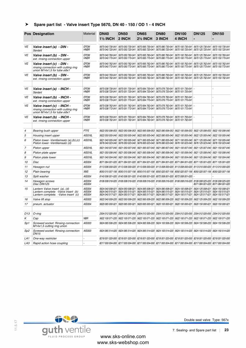
7 . 2 Spare part list DN 40 - 150 / OD 1 - 4 INCH
Double seat valve Type 567x, DN 40 - 150 / OD 1 - 4 INCH (1.4404 / AISI316L)
Housing variation Seal Article-No. Valve insert VE Seal kit
1.) Standard
SS - S EPDM 5671 DN 730-xxx5670 DN 730-041 a) 5670 DN 739-020
b) 5670 DN 739-000= with backup ring for (D4)= without backup ring for (D4)
S - S 5672 DN 730-xxxS - SS 5673 DN 730-xxx
SS - SS 5674 DN 730-xxxSS - S HNBR 5671 DN 720-xxx
5670 DN 720-041 a) 5670 DN 729-020b) 5670 DN 729-000
= with backup ring for (D4)= without backup ring for (D4)
S - S 5672 DN 720-xxxS - SS 5673 DN 720-xxx
SS - SS 5674 DN 720-xxx
2.) ext. rinsing connection upper
SS - S EPDM 5671 DN 760-xxx5670 DN 760-041 a) 5670 DN 769-020
b) 5670 DN 769-000= with backup ring for (D4)= without backup ring for (D4)
S - S 5672 DN 760-xxxS - SS 5673 DN 760-xxx
SS - SS 5674 DN 760-xxxSS - S HNBR 5671 DN 770-xxx
5670 DN 770-041 a) 5670 DN 779-020b) 5670 DN 779-000
= with backup ring for (D4)= without backup ring for (D4)
S - S 5672 DN 770-xxxS - SS 5673 DN 770-xxx
SS - SS 5674 DN 770-xxx
3.) rinsing connection with cutting ring union M14x1,5 for tube ø8x1
SS - S EPDM 5671 DN 762-xxx5670 DN 762-041 a) 5670 DN 769-020
b) 5670 DN 769-000= with backup ring for (D4)= without backup ring for (D4)
S - S 5672 DN 762-xxxS - SS 5673 DN 762-xxx
SS - SS 5674 DN 762-xxxSS - S HNBR 5671 DN 772-xxx
5670 DN 772-041 a) 5670 DN 779-020b) 5670 DN 779-000
= with backup ring for (D4)= without backup ring for (D4)
S - S 5672 DN 772-xxxS - SS 5673 DN 772-xxx
SS - SS 5674 DN 772-xxx
4.) ext. rinsing connection lower
SS - S EPDM 5671 DN 793-xxx5670 DN 793-041 a) 5670 DN 799-020
b) 5670 DN 799-000= with backup ring for (D4)= without backup ring for (D4)
S - S 5672 DN 793-xxxS - SS 5673 DN 793-xxx
SS - SS 5674 DN 793-xxxSS - S HNBR 5671 DN 792-xxx
5670 DN 792-041 a) 5670 DN 798-020b) 5670 DN 798-000
= with backup ring for (D4)= without backup ring for (D4)
S - S 5672 DN 792-xxxS - SS 5673 DN 792-xxx
SS - SS 5674 DN 792-xxxDN = Nominal diameter e.g. 5673 050 130-041 = DN50 , 5673 051 130-041 = 2INCHxxx = Material in product contact/ Exterior finish / Interrogation system (see 10. classification)S = Welded end
Pos Designation Material DN401½ INCH
DN502 INCH
DN652½ INCH
DN803 INCH
DN1004 INCH
DN125-
DN150-
1 Housing SS - SDIN S - S
S - SSSS - SS
AISI316L 5621 040 001-0415622 040 001-0415623 040 001-0415624 040 001-041
5621 050 001-0415622 050 001-0415623 050 001-0415624 050 001-041
5621 065 001-0415622 065 001-0415623 065 001-0415624 065 001-041
5621 080 001-0415622 080 001-0415623 080 001-0415624 080 001-041
5621 100 001-0415622 100 001-0415623 100 001-0415624 100 001-041
5621 125 001-0415622 125 001-0415623 125 001-0415624 125 001-041
5621 150 001-05622 150 001-05623 150 001-05624 150 001-0
1 Housing SS - SINCH S - S
S - SSSS - SS
AISI316L 5661 040 001-0415662 040 001-0415663 040 001-0415664 040 001-041
5661 050 001-0415662 050 001-0415663 050 001-0415664 050 001-041
5661 065 001-0415662 065 001-0415663 065 001-0415664 065 001-041
5661 080 001-0415662 080 001-0415663 080 001-0415664 080 001-041
5661 100 001-0415662 100 001-0415663 100 001-0415624 100 001-041
5661 125 001-0415662 125 001-0415663 125 001-0415664 125 001-041
5661 150 001-05662 150 001-05663 150 001-05664 150 001-0
2 Housing bottomHousing bottom
AISI303AISI303
5671 040 008-2205676 040 023-220
5671 050 008-2205676 050 023-220
5671 065 008-2205676 065 023-220
5671 080 008-2205676 080 023-220
5671 100 008-2205676 100 023-220
5671 125 008-2205676 125 023-220
5671 150 008-25676 150 023-2
3 Retaining clamp (2x) AISI304 2122 065 100-020 2122 065 100-020 2122 080 100-020 2122 115 100-020 2122 125 100-020 2122 150 100-020 2122 200 100-0
4 Bearing bush lower PTFE 5622 050 006-053 5622 050 006-053 5622 065 006-053 5622 080 006-053 5622 100 006-053 5622 125 006-053 5622 150 006-0
5 Housing insert lower AISI316L 5622 050 005-040 5622 050 005-040 5622 065 005-040 5622 080 005-040 5622 100 005-040 5622 125 005-040 5622 150 005-0
D1 Seal(included in seal kit)
EPDMHNBR
5622 050 010-0695622 050 010-050
5622 050 010-0695622 050 010-050
5622 065 010-0695622 065 010-050
5622 080 010-0695622 080 010-050
5622 100 010-0695622 100 010-050
5622 125 010-0695622 125 010-050
5622 150 010-05622 150 010-0
D2 O-ring (2x)(included in seal kit)
EPDMHNBR
2304 069 026-1592304 069 026-050
2304 069 026-1592304 069 026-050
2304 082 026-1592304 082 026-050
2304 098 035-1592304 098 035-050
2304 117 035-1592304 117 035-050
2304 142 035-1592304 142 035-050
2304 177 035-12304 177 035-0
Double seat valve Type: 567x
7. Sealing- and Spare part list 22
www.sks-online.com www.sks-webshop.com
11.5
.17
4141
4141
4141
4141
40
40
4040
40
40
40
20
20
56
2020
212121
20
21
55
20
20
20
00
00
Spare part list - Valve insert Type 5670, DN 40 - 150 / OD 1 - 4 INCH
Pos Designation Material DN401½ INCH
DN502 INCH
DN652½ INCH
DN803 INCH
DN1004 INCH
DN125-
DN150-
VE Valve insert (a) - DIN -Standard
EPDMHNBR
5670 040 730-0415670 040 720-041
5670 050 730-0415670 050 720-041
5670 065 730-0415670 065 720-041
5670 080 730-0415670 080 720-041
5670 100 730-0415670 100 720-041
5670 125 730-0415670 125 720-041
5670 150 730-05670 150 720-0
VE Valve insert (b) - DIN -ext. rinsing connection upper
EPDMHNBR
5670 040 760-0415670 040 770-041
5670 050 760-0415670 050 770-041
5670 065 760-0415670 065 770-041
5670 080 760-0415670 080 770-041
5670 100 760-0415670 100 770-041
5670 125 760-0415670 125 770-041
5670 150 760-05670 150 770-0
VE Valve insert (c) - DIN -rinsing connection with cutting ring union M14x1,5 for tube ø8x1
EPDMHNBR
5670 040 762-0415670 040 772-041
5670 050 762-0415670 050 772-041
5670 065 762-0415670 065 772-041
5670 080 762-0415670 080 772-041
5670 100 762-0415670 100 772-041
5670 125 762-0415670 125 772-041
5670 150 762-05670 150 772-0
VE Valve insert (b) - DIN -ext. rinsing connection upper
EPDMHNBR
5670 040 793-0415670 040 792-041
5670 050 793-0415670 050 792-041
5670 065 793-0415670 065 792-041
5670 080 793-0415670 080 792-041
5670 100 793-0415670 100 792-041
5670 125 793-0415670 125 792-041
5670 150 793-05670 150 792-0
VE Valve insert (a) - INCH -Standard
EPDMHNBR
5670 038 730-0415670 038 720-041
5670 051 730-0415670 051 720-041
5670 064 730-0415670 064 720-041
5670 076 730-0415670 076 720-041
5670 101 730-0415670 101 720-041
- -
VE Valve insert (b) - INCH -ext. rinsing connection upper
EPDMHNBR
5670 038 760-0415670 038 770-041
5670 051 760-0415670 051 770-041
5670 064 760-0415670 064 770-041
5670 076 760-0415670 076 770-041
5670 101 760-0415670 101 770-041
- -
VE Valve insert (c) - INCH -rinsing connection with cutting ring union M14x1,5 for tube ø8x1
EPDMHNBR
5670 038 762-0415670 038 772-041
5670 051 762-0415670 051 772-041
5670 064 762-0415670 064 772-041
5670 076 762-0415670 076 772-041
5670 101 762-0415670 101 772-041
- -
VE Valve insert (b) - INCH -ext. rinsing connection upper
EPDMHNBR
5670 038 793-0415670 038 792-041
5670 051 793-0415670 051 792-041
5670 064 793-0415670 064 792-041
5670 076 793-0415670 076 792-041
5670 101 793-0415670 101 792-041
- -
4 Bearing bush upper PTFE 5622 050 006-053 5622 050 006-053 5622 065 006-053 5622 080 006-053 5622 100 006-053 5622 125 006-053 5622 150 006-0
5 Housing insert upper AISI316L 5622 050 005-040 5622 050 005-040 5622 065 005-040 5622 080 005-040 5622 100 005-040 5622 125 005-040 5622 150 005-0
6 Piston lower -Ventileinsatz (a),(b),(c)Piston lower -Ventileinsatz (d)
AISI316L 5621 040 005-0405676 040 023-040
5671 050 005-0405676 050 023-040
5671 065 005-0405676 065 023-040
5671 080 005-0405676 080 023-040
5671 100 005-0405676 100 023-040
5671 125 005-0405676 125 023-040
5671 150 005-05676 150 023-0
7 Piston upper AISI316L 5621 040 007-040 5621 050 007-040 5621 065 007-040 5621 080 007-040 5621 100 007-040 5621 125 007-040 5621 150 007-0
8 Piston plate upper AISI316L 5621 050 006-040 5621 050 006-040 5621 065 006-040 5621 080 006-040 5621 100 006-040 5621 125 006-040 5621 150 006-0
9 Piston plate lower AISI316L 5621 040 004-040 5621 050 004-040 5621 065 004-040 5621 080 004-040 5621 100 004-040 5621 125 004-040 5621 150 004-0
10 Disc AISI304 8071 064 001-020 8071 064 001-020 8071 064 001-020 8071 084 001-020 8071 084 001-020 8071 105 001-020 8071 105 001-0
11 Hexagon nut AISI304 8113 006 000-020 8113 006 000-020 8113 006 000-020 8113 008 000-020 8113 008 000-020 8113 010 000-020 8113 010 000-0
12 Plain bearing XMS 8050 015 007-156 8050 015 007-156 8050 015 007-156 8050 020 007-156 8050 020 007-156 8050 020 007-156 8050 020 007-1
13 Split washer AISI304 8140 006 001-020 8140 006 001-020 8140 006 001-020 8072 008 001-020 8072 008 001-020 - -
14 Hexagon screwsDisc DIN125
AISI304AISI304
8106 008 016-020-
8106 008 016-020-
8106 008 016-020-
8106 008 016-020-
8106 008 016-020-
8106 008 025-0208071 084 001-020
8106 008 025-08071 084 001-0
15 Lantern Valve insert (a), (d)Lantern complete -Valve insert (b)Lantern complete. -Valve insert (c)
AISI304AISI304AISI304
5624 040 008-0215624 040 515-0215624 040 517-021
5624 050 008-0215624 050 515-0215624 050 517-021
5624 065 008-0215624 065 515-0215624 065 517-021
5624 080 008-0215624 080 515-0215624 080 517-021
5624 100 008-0215624 100 515-0215624 100 517-021
5624 125 008-0215624 125 515-0215624 125 517-021
5624 150 008-05624 150 515-05624 150 517-0
16 Valve lift stop AISI303 5622 040 009-220 5622 050 009-220 5622 065 009-220 5622 080 009-220 5622 100 009-220 5622 125 009-220 5622 150 009-2
17 pneum. actuator AISI304 5620 065 000-021 5620 065 000-021 5620 065 000-021 5620 100 000-021 5620 100 000-021 5620 150 000-021 5620 150 000-0
D13 O-ring 2304 012 020-055 2304 012 020-055 2304 012 020-055 2304 012 020-055 2304 012 020-055 2304 012 020-055 2304 012 020-0
K Cap NBR 5622 100 071-220 5622 100 071-220 5622 100 071-220 5622 100 071-220 5622 100 071-220 5622 100 071-220 5622 100 071-2
Sp1 Screwed socket: Rinsing connection M14x1,5 cutting ring union
AISI303 5624 065 506-220 5624 065 506-220 5624 065 506-220 5624 100 506-220 5624 100 506-220 5624 150 506-220 5624 150 506-2
Sp2 Screwed socket: Rinsing connection DN15
AISI303 5624 065 514-020 5624 065 514-020 5624 065 514-020 5624 100 514-020 5624 100 514-020 5624 150 514-020 5624 150 514-0
LA1 One-way restricter - 8218 001 020-000 8218 001 020-000 8218 001 020-000 8218 001 020-000 8218 001 020-000 8218 001 020-000 8218 001 020-0
LA3 Rapid action hose coupling - 8217 000 004-000 8217 000 004-000 8217 000 004-000 8217 000 004-000 8217 000 004-000 8217 000 004-000 8217 000 004-0
Double seat valve Type: 567x
7. Sealing- and Spare part list 23
www.sks-online.com www.sks-webshop.com

11.5
.17
00
00
00
69
70
70
59
59
70
40
59
59
55
70
20
00
00
00
50
50
70
57
57
70
40
59
59
55
70
20
Seal kits Double seat valve Type 567x, DN 40 - 150 / OD 1 - 4 INCH
a) Seal kit with backup ring for (D4)b) Seal kit without backup ring for (D4)
a) Seal kit with backup ring for (D4)b) Seal kit without backup ring for (D4)
Pos Designation Material DN401½ INCH
DN502 INCH
DN652½ INCH
DN803 INCH
DN1004 INCH
DN125-
DN150-
Seal kit EPDM (A) - Standard
EPDM a)EPDM b)
5670 040 739-0205670 040 739-000
5670 050 739-0205670 050 739-000
5670 065 739-0205670 065 739-000
5670 080 739-0205670 080 739-000
5670 100 739-0205670 100 739-000
5670 125 739-0205670 125 739-000
5670 150 739-0-
Seal kit EPDM (B)- Rinsing connection upper
EPDM a)EPDM b)
5670 040 769-0205670 040 769-000
5670 050 769-0205670 050 769-000
5670 065 769-0205670 065 769-000
5670 080 769-0205670 080 769-000
5670 100 769-0205670 100 769-000
5670 125 769-0205670 125 769-000
5670 150 769-0-
Seal kit EPDM (C)- Rinsing connection lower
EPDM a)EPDM b)
5670 040 799-0205670 040 799-000
5670 050 799-0205670 050 799-000
5670 065 799-0205670 065 799-000
5670 080 799-0205670 080 799-000
5670 100 799-0205670 100 799-000
5670 125 799-0205670 125 799-000
5670 150 799-0-
D1 Shaft seal (2x) EPDM 5622 050 010-069 5622 050 010-069 5622 065 010-069 5622 080 010-069 5622 100 010-069 5622 125 010-069 5622 150 010-0
D2 O-ring (4x) EPDM 2304 069 026-159 2304 069 026-159 2304 082 026-159 2304 098 035-159 2304 117 035-159 2304 142 035-159 2304 177 035-1
D3 O-ring EPDM 2304 026 015-170 2304 026 015-170 2304 029 015-170 2304 042 020-170 2304 036 020-170 2304 036 020-170 2304 036 020-1
D4D4
Seal (2x)Seal (2x) two-parts (till 05/2016)
EPDM EPDM
-5621 055 025-084
-5621 055 025-084
-5621 065 025-084
-5621 080 025-084
-5621 100 025-084
-2304 113 025-084
2304 133 053-1-
D5 O-ring EPDM 2304 041 035-159 2304 041 035-159 2304 050 035-159 2304 066 035-159 2304 085 035-159 2304 111 035-084 2304 140 035-1
D6 O-ring EPDM 2304 038 018-170 2304 038 018-170 2304 048 020-170 2304 057 020-170 2304 076 020-170 2304 092 035-159 2304 108 035-1
D7 Headless pin AISI316L 8112 006 050-040 8112 006 060-040 8112 006 085-040 8112 008 050-040 8112 008 085-040 8112 010 065-020 8112 010 090-0
D8 O-ring (2x) EPDM 2304 036 035-159 2304 036 035-159 2304 036 035-159 2304 041 035-159 2304 041 035-159 2304 041 035-159 2304 041 035-1
D9 O-ring EPDM 2304 047 035-159 2304 047 035-159 2304 057 035-159 2304 069 035-159 2304 092 035-159 2304 117 035-159 2304 142 035-1
D10 O-ring NBR 2304 042 025-055 2304 042 025-055 2304 042 025-055 2304 046 025-055 2304 046 025-055 2304 046 025-055 2304 046 025-0
D11 O-ring (1x) (Seal kit B)O-ring (2x) (Seal kit C)
EPDM 2304 014 020-170 2304 014 020-170 2304 014 020-170 2304 014 020-170 2304 016 020-170 2304 016 020-170 2304 016 020-1
D12 O-ring (2x) (only seal kit C) EPDM - 2304 036 035-159 2304 054 035-159 2304 082 035-159 - - -
11 Hexagon nut AISI304 8113 006 000-020 8113 006 000-020 8113 006 000-020 8113 008 000-020 8113 008 000-020 8113 010 000-020 8113 010 000-0
Pos Designation Material DN401½ INCH
DN502 INCH
DN652½ INCH
DN803 INCH
DN1004 INCH
DN125-
DN150-
Seal kit HNBR (A) - Standard
HNBR a)HNBR b)
5670 040 729-0205670 040 729-000
5670 050 729-0205670 050 729-000
5670 065 729-0205670 065 729-000
5670 080 729-0205670 080 729-000
5670 100 729-0205670 100 729-000
5670 125 729-0205670 125 729-000
5670 150 729-0-
Seal kit HNBR (B)- Rinsing connection upper
HNBR a)HNBR b)
5670 040 779-0205670 040 779-000
5670 050 779-0205670 050 779-000
5670 065 779-0205670 065 779-000
5670 080 779-0205670 080 779-000
5670 100 779-0205670 100 779-000
5670 125 779-0205670 125 779-000
5670 150 779-0-
Seal kit HNBR (C)- Rinsing connection lower
HNBR a)HNBR b)
5670 040 798-0205670 040 798-000
5670 050 798-0205670 050 798-000
5670 065 798-0205670 065 798-000
5670 080 798-0205670 080 798-000
5670 100 798-0205670 100 798-000
5670 125 798-0205670 125 798-000
5670 150 798-0-
D1 Shaft seal (2x) HNBR 5622 050 010-050 5622 050 010-050 5622 065 010-050 5622 080 010-050 5622 100 010-050 5622 125 010-050 5622 150 010-0
D2 O-ring (4x) HNBR 2304 069 026-050 2304 069 026-050 2304 082 026-050 2304 098 035-050 2304 117 035-050 2304 142 035-050 2304 177 035-0
D3 O-ring EPDM 2304 026 015-170 2304 026 015-170 2304 029 015-170 2304 042 020-170 2304 036 020-170 2304 036 020-170 2304 036 020-1
D4D4
Seal (2x)Seal (2x) two-parts (till 05/2016)
HNBR HNBR
-5621 055 025-171
-5621 055 025-171
-5621 065 025-171
-5621 080 025-171
-5621 100 025-171
-2304 113 025-171
2304 133 053-1-
D5 O-ring HNBR 2304 041 035-157 2304 041 035-157 2304 050 035-157 2304 066 035-157 2304 085 035-157 2304 111 035-157 2304 140 035-1
D6 O-ring EPDM 2304 038 018-170 2304 038 018-170 2304 048 020-170 2304 057 020-170 2304 076 020-170 2304 092 035-159 2304 108 035-1
D7 Headless pin AISI316L 8112 006 050-040 8112 006 060-040 8112 006 085-040 8112 008 050-040 8112 008 085-040 8112 010 065-020 8112 010 090-0
D8 O-ring (2x) EPDM 2304 036 035-159 2304 036 035-159 2304 036 035-159 2304 041 035-159 2304 041 035-159 2304 041 035-157 2304 041 035-1
D9 O-ring EPDM 2304 047 035-159 2304 047 035-159 2304 057 035-159 2304 069 035-159 2304 092 035-159 2304 117 035-159 2304 142 035-1
D10 O-ring NBR 2304 042 025-055 2304 042 025-055 2304 042 025-055 2304 046 025-055 2304 046 025-055 2304 046 025-055 2304 046 025-0
D11 O-ring (1x) (Seal kit B)O-ring (2x) (Seal kit C)
EPDM 2304 014 020-170 2304 014 020-170 2304 014 020-170 2304 014 020-170 2304 016 020-170 2304 016 020-170 2304 016 020-1
D12 O-ring (2x) (only seal kit C) EPDM - 2304 036 035-159 2304 054 035-159 2304 082 035-159 - - -
11 Hexagon nut AISI304 8113 006 000-020 8113 006 000-020 8113 006 000-020 8113 008 000-020 8113 008 000-020 8113 010 000-020 8113 010 000-0
Double seat valve Type: 567x
7. Sealing- and Spare part list 24
www.sks-online.com www.sks-webshop.com

11.5
.17
8 . C l a s s i f i c a t i o n
8 . 1 Structure of Order Number
Product = Double seat valve with in product contact seals EPDM or HNBR
0 1 2 3 4 5 6 7 8 9 10 11 12 13 145 6 7 1 0 5 0 7 3 0 - G 6 0 9
Control system / Feedback unit / Surfaces finish
Separator
Sealing materialConsstruction modification
Valve size DN/OD
Housing type
Product type
0 - 2 Product type 567x xxx xxx-xxxx
3 Housing type 567x xxx xxx-xxxx
Housing 35670 without housing (valve insert) - 0
5671 SS - S 1
5672 S - S 2
5673 S - SS 3
5674 SS - SS 4
4 - 6 Valve size DN/OD 567x xxx xxx-xxxx
DN 4 5 6 OD 4 5 6DN 25 0 2 5 OD 1" 0 2 6DN 40 0 4 0 OD 1 1/2" 0 3 8DN 50 0 5 0 OD 2 " 0 5 1DN 65 0 6 5 OD 2 1/2" 0 6 4DN 80 0 8 0 OD 3 " 0 7 6DN 100 1 0 0 OD 4 " 1 0 1DN 125 1 2 5 OD 5" 1 2 7DN 150 1 5 0 OD 6 " 1 5 2
Double seat valve Type: 567x
8. Classification 25
www.sks-online.com www.sks-webshop.com

11.5
.17
- KIESELMANN valve
7 - 9 Sealing material
& Construction modification 567x xxx xxx-xxxx
in product contact Seals & modifications 7 8 9EPDM 7 3 0HNBR 7 2 0EPDM - external rinsing connection upper 7 6 0HNBR - external rinsing connection upper 7 7 0EPDM - external rinsing connection lower 7 9 3HNBR - external rinsing connection lower 7 9 2EPDM - Screwed socket: Rinsing connection M14x1,5 cutting ring union 7 6 2HNBR - Screwed socket: Rinsing connection M14x1,5 cutting ring union 7 7 2
10 Separator 567x xxx xxx-xxxx
11 - 14 Control system / Feedback unit
/ Surfaces finish 567x xxx xxx-xxxx
control system / feedback unit / surfaces finish 11 12 13 14Guth-valve without control system, surfaces, AISI304, blank 0 2 0Guth-valve without control system, surfaces, AISI304, e-polished 0 2 1Guth-valve without control system, surfaces, AISI304, matt 0 2 2Guth-valve without control system, surfaces, AISI316L, blank 0 4 0Guth-valve without control system, surfaces, AISI316L, e-polished 0 4 1Guth-valve without control system, surfaces, AISI316L, matt 0 4 2Guth-valve mit Rückmeldeeinheit (5630 005 000-020) 7 5 0Guth-valve with control head KI-Top SPS for double seat valves G 5 x xGuth-valve with control head KI-Top ASi-Bus for double seat valves G 6 x x
Double seat valve Type: 567x
8. Classification 26
www.sks-online.com www.sks-webshop.com

Landau, 01.07.2016
Oliver HeckerGeneral Manager
The manufacturer hereby states that the above product is considered as an incomplete machine in the sense defined in theDirective 2006/42/EC on Machinery. The above product is exclusively intended to be installed into a machine or an incompletemachine. The said product does not yet conform to all the relevant requirements defined in the Directive on Machinery referredto above for this reason.
The specific technical documents listed in Appendix VII, Part B, have been prepared. The Authorized Agent empowered tocompile technical documents may submit the relevant documents if such a request has been properly justified.
Commissioning of an incomplete machine must not only carried out if it has been determined that the respective machine intowhich the incomplete machine is to be installed conforms to the regulations set out in the Directive on Machinery referred toabove.
The above product conforms to the requirements of the directives and harmonized standards specified below:
D e c l a r a t i o n o f i n c o r p o r a t i o n
Translation of the original
Manufacturer / authorised representative: Guth Ventiltechnik GmbHHorstring 1676829 LandauGermany
Authorised representative, for compiling technical documents:
Achim KauselmannDocumentation / DevelopmentKIESELMANN GmbH
Product Function
pneum. Lift actuators pneum. Rotary actuators Ball valvesButterfly valves Single seat valves Flow control valves Throttle valve Overflow valve Double seat valve Bellow valves Sampling valves Two way valves Tankdome fittingSafety valve
Stroke movement Rotary movement Media cutoff Media cutoff Media cutoffControl of liquefied media Control of liquefied media Definition of fluid pressure Media separation Sampling of liquids Sampling of liquidsMedia cutoffPrevention of overpressure and vacuum, Tank cleaningPrevention of overpressure
• Directive 2014/68/EU• DIN EN ISO 12100 Safety of machinery
www.sks-online.com www.sks-webshop.com