Embed Size (px)
Citation preview

56800E
freescale.com
16-Bit Digital Signal Controllers
56800E Flash Programmer User Guide
56800EFPUGRev. 009/2005

56800E Flash Programmer User Guide, Rev. 0
2 Freescale Semiconductor
Document Revision History
Version History Description of Change
Rev 0 Initial release

56800E Flash Programmer User Guide, Rev. 0
Freescale Semiconductor 3
56800E Flash Programmer User GuideThe 56800E Flash Programmer provides a means to program the on-chip Flash of the 56800E DSC family. The Flash Memory blocks are programmed in circuit, using the JTAG/EOnCE interface. The 56800E Flash Programmer is suitable for both a low volume production environment as well as for in-field firmware upgrades.
The 56800E Flash Programmer runs under a 32-bit Windows environment on PC compatible computers. A Parallel Command Converter or CodeWarrior USB TAP is needed to provide the interface between the JTAG/OnCE interface of the target system and the computer. The connection is outlined in the figure below.
Figure 1 Connecting the Target System to the PC via Parallel Command Connector
Figure 2 Connecting the Target System to the PC via USB Tap
The 56800E Flash Programmer is provided in two forms. The first is command-line oriented to allow easy integration with scripts. The second is a GUI running under windows to allow easy rapid Flash loading onto the target device. The command line version is backwards compatible with the old Flash over JTAGtool.
Cable
PC-CompatibleComputer
JTAG
Power
ParallelCommandConverter
Target System
Parallel Extention
PC-CompatibleComputer
JTAG
Power
Target System
USB Cable
USB TAP

56800E Flash Programmer User Guide, Rev. 0
4 Freescale Semiconductor
1. Corrections to CodeWarrior v7.2 Configuration FilesThe configuration files in CodeWarrior v7.2 may need to be modified depending on the device or devices to be programmed. These files will be corrected in CodeWarrior v7.3. They are typically found in the following location:
C:\Program Files\Metrowerks\CodeWarrior\M56800E Support\initialization
For the 56F801x devices, change the following line in the file 56801x_flash.cfg
set_hfm_programmer_base 0x8746 # shared p-ram
to
set_hfm_programmer_base 0x8700 # shared p-ram
For the 56F835x device, change the following line in the file 56835x_flash.cfg
set_hfm_config_base 0x00FFF7
to
set_hfm_config_base 0x01FFF7
The first correction is required for the 56F8013 and 56F8014; programming will fail if the modification is not applied. The second correction for the 56F8355, 56F8356, and 56F8357 is only required if it is desired to use the lock flash after programming feature.
2. 56800E Flash Programmer DescriptionThe 56800E Flash Programmer runs under 32-bit Windows operating systems.
Before loading to the actual device, the 56800E Flash Programmer will first create a Virtual Device Imageon the Host PC. The Virtual Device Image contains all of the memory to be programmed on the device allowing for all of the S-Record, or executable and linking format (ELF) files, to be loaded and verified before any programming begins. Additionally, the 56800E Flash Programmer allows certain operations to be performed on the Virtual Device Image as if it was a real device; however, this feature is only supported in the Command-Line version.
2.1 Command-Line VersionThe command line version executes in a DOS window and accepts command line parameters to control its operation. The command line interface is very effective when the 56800E Flash Programmer needs to be integrated into scripts or executed by other programs controlling the manufacturing process. All the mandatory parameters are indicated by ‘<>’ brackets and optional parameters are indicated by ‘[]’ brackets. The syntax has the following two variants:

Command-Line Version
56800E Flash Programmer User Guide, Rev. 0
Freescale Semiconductor 5
1. fflash <flash config file> <S-Record/ELF file 1> [S-Record/ELF file 2] [.] [S-Record/ ELF file N] [options]
2. fflash <flash config file> [options]Certain operations, such as recovery, are performed when no S-Record or ELF file is provided.
The configuration files can be typically found in the following directory on the PC:
C:\Program Files\Metrowerks\CodeWarrior\M56800E Support\initialization
2.1.1 OptionsPosition of options on the command line is not fixed. They can be specified before, between, or after the configuration and the list of S-Record ,or ELF files to be loaded.
All options with the text Legacy Support, indicate they remain to support the old Flash over JTAGapplication. These options are deprecated. They indicate what options should be used instead.
2.1.1.1 –crcPerforms a 32-bit cyclical redundancy check (CRC) from a start address to an end address, and reports the 32-bit CRC to the user. This can be used in conjunction with the –dumpvirtual to dump the 32-bit CRC of a file without loading it onto the device.
Example: fflash flash.cfg my_appl.S –crcP0x0-0x1fff
2.1.1.2 –dBy default, the tool resets the target after programming is concluded and program execution will occur. This option forces the tool to leave the target in Debug mode, i.e. the downloaded code is not executed immediately after programming.
Example: fflash flash.cfg my_appl.S –d
2.1.1.3 –dumpvirtualWhen used in conjunction with the –r/–v/–crc switch’s parameters, the contents of the virtual device on the computer will be dumped to a S-Record, or ELF file, instead of reading the contents off of the actual Digital Signal Controller (DSC) device.
Example: fflash flash.cfg my_appl.S –dumpvirtual –vP0x0:0x1fff
2.1.1.4 –erase=<all|unit|page>This parameter tells the programmer how the device should be erased by any one of three modes before any programming occurs:

56800E Flash Programmer User Guide, Rev. 0
6 Freescale Semiconductor
1. When the mode is set to all, the entire device is erased before any programming occurs; however, the mode does not perform a recovery and can still fail if the Flash is secured. In this case, use the –recover option.
2. When the mode is set to unit, only the specific unit requiring programming will be erased. A unit is defined by the add_hfm_unit token in the Flash configuration file and is generally referring to Boot, Program, or Data Flash blocks.
3. When the mode is set to page, only the specific page of Flash requiring programming will be erased. Using the unit or page mode is useful when wishing to preserve information currently stored in either a particular Flash block or page. By default this parameter is unit.
Example: fflash flash.cfg my_appl.S –erase=page
2.1.1.5 –fastportLegacy Support
This option is no longer supported. The previous version of the Flash over JTAG tool would attempt to communicate with the Parallel Command Converter as quickly as the LPT port would allow. Some LPT ports would operate too fast for the DSC to remain aligned, therefore this option was provided. This is no longer required because the JTAG clock speed can now be set more specifically through the –jtagclk=X option.
2.1.1.6 –jtagclk=<x>This option tells the CCS server the frequency (kHz) at which to run the JTAG interface. The default value is 800kHz. Faster clock speeds allow for faster programming, but if the clock is set too fast, the DSC chip may not be able to process incoming data quickly enough, eventually leading to a programming failure.
Example: fflash flash.cfg my_appl.S –jtagclk=1000
2.1.1.7 –l<log file>This option forces all messages shown on the screen to be written into the Log File. If the file already exists, it will be overwritten.
Example: fflash flash.cfg my_appl.S –lmylog.txt
2.1.1.8 –lockThis option will lock the device by enabling Flash security. This option writes 0xE70A to the SECLO_VALUE location in the Flash Security Configuration table of Program Flash. If an S-Record or, ELF file is provided, this location is written to after the S-Record, or ELF file is loaded. This option can also be used in combination with the –recover option, allowing the program to recover from the locked state, load the S-Record, then proceed to relock the device, allowing an upgrade of a LOCKED device. The 56800E Flash Programmer verifies the SECLO_VALUE location is 0xFFFF before the location is written to. If the location is not 0xFFFF the programming of this location cannot proceed and an error is received. Please note this only enables Flash Security. Any advanced options, such as back door enable and the back door key will require a loadable S-Record, or ELF file defining this data.
Example: fflash flash.cfg my_appl.S –lock

Command-Line Version
56800E Flash Programmer User Guide, Rev. 0
Freescale Semiconductor 7
2.1.1.9 –LPT<X>By default, the 56800E Flash Programmer uses the current configured device on the CCS server. How-ever, the default can be overridden by the –USB or –LPTX switches. The LPT switch will configures the CCS server for the Parallel Command Converter. Additionally, this change will be permanent to CCS, and may need to be changed before other applications use the CCS server. When connecting to a remote CCS server using the –remote switch, the remote server will be configured to use this LPT port.
Example: fflash flash.cfg my_appl.S .LPT1
2.1.1.10 –p<PORT>Legacy Support
This option is used to specify which LPT port to use when connecting to a Parallel Command Converter. When this option is specified, along with the –remote option, it connects to the specified LPT port on that remote device. Because this command is deprecated, it only supports the addresses listed in Table 2-1. No other address will be supported. The option –LPTX should be used in place of this deprecated option.
Example: fflash flash.cfg my_appl.s –p0x378

56800E Flash Programmer User Guide, Rev. 0
8 Freescale Semiconductor
2.1.1.11 –pageLegacy Support
This option specifies a Page Erase mode should be used instead of the Mass Erase mode. This parameter is useful for in-field upgrades where parameters stored in on-chip Flash must be preserved. In this case, only pages containing addresses referenced by the S-Record file will be erased. As this option is deprecated, the –erase=X option should be used instead. This option is identical to –erase=page.
Example: fflash flash.cfg my_appl.s –page
2.1.1.12 –r<mem><start>:<end>This option causes the contents of the DSC memory to be dumped to the specified S-Record file. If the output file already exists, it is overwritten.’<mem>’ specifies whether Data (‘X’) or Program (‘P’) memory should be dumped. Addresses, ‘<start>’ and ‘<end>’, are expressed in hexadecimal.
Examples: fflash flash.cfg readout_x.S –rX0x0:0xfff fflash flash.cfg readout_p.S –rP0x0:0xfff
2.1.1.13 –recoverThis option disables Flash Security by erasing ALL on-chip Flash units of the DSC. Please note the contents of ALL on-chip Flash units are lost and cannot be recovered after performing this algorithm. When the recover switch is provided in combination with a S-Record, or ELF file, the program will first recover the Flash before programming the new S-Record, or ELF file onto the Flash.
Example: fflash flash.cfg –recoverfflash flash.cfg my_appl.S –recover
2.1.1.14 –remote=Address[:port]By default, the 56800E Flash Programmer connects to the local computer’s CCS server and attempts to use it to program the DSC device. However, it is possible to program a device connected to a remote computer’s CCS server. When the remote option is specified, the address of the remote CCS server is required; nonetheless, the port is optional. The default value of the port is 41475. Changing the port value is useful when the CCS server is behind a firewall. Contact your network administrator for more information about which ports are open.
NOTE: The IP address of the local computer is 127.0.0.1.
Examples:
Table 2-1 Typical Addresses Assigned to LPT Ports on IBM-PC Machines
LPT# Base AddressLPT1 0x378LPT2 0x278LPT3 0x3BC

Command-Line Version
56800E Flash Programmer User Guide, Rev. 0
Freescale Semiconductor 9
Connects to the local computer, at port 1000fflash flash.cfg my_appl.S –remote=127.0.0.1:1000
Connects to the remote CCS server at IP address 1.2.3.4fflash flash.cfg my_appl.S–remote=1.2.3.4
Connects to the remote CCS server named BOBfflash flash.cfg my_appl.S –remote=BOB
Connects to the remote CCS server at IP address 1.2.3.4 at port 1000fflash flash.cfg my_appl.S –remote=1.2.3.4:1000
2.1.1.15 –sThis option enables Silent mode. Normally the 56800E Flash Programmer reports an error for each word of data, or code, found in the specified S-Record not fitting into any of the address ranges of the Flash blocks defined in the Flash configuration file. When Silent mode is enabled, the 56800E Flash Programmer only reports some data was ignored, but it does not print any further details.
Example: fflash flash.cfg my_appl.S –s
2.1.1.16 –t<S-record file> Legacy Support
This option has the same behavior as simply specifying additional S-Records, or ELF files, on the command line; however, using the –t guarantees it will be the last S-Record, or ELF file, loaded in the chain.
Example: fflash flash.cfg my_app.S –tserial.S
2.1.1.17 –timeout=<x>This option determines the wait length in seconds for the CCS server to respond before it will abort and return an error. The default value is 5 seconds.
Example: fflash flash.cfg my_appl.S –timeout=10
2.1.1.18 –USBBy default, the 56800E Flash Programmer uses the current configured device on the CCS server. However, the default can be overridden by the –USB or –LPTX switches. The USB switch configures the CCS server for the CodeWarrior USB TAP device. Additionally, this change is permanent to CCS, and may need to be changed before other applications use the CCS server. When connecting to a remote CCS server using the –remote switch, the remote server will be configured to use the USB port.
Example: fflash flash.cfg my_appl.S –USB
2.1.1.19 –v<mem><start>:<end>This option allows the user to view the DSC memory by dumping the contents of the memory to the screen. ‘<mem>’ specifies whether Data (‘X’) or Program (‘P’) memory should be dumped. Addresses, ‘<start>’ and ‘<end>’, are expressed in hexadecimal.

56800E Flash Programmer User Guide, Rev. 0
10 Freescale Semiconductor
Examples: fflash flash.cfg –vX0x0:0x1000 fflash flash.cfg –vP0x0:0x1000
2.1.1.20 –verifyThis option does not load the data onto the device. A 32-bit CRC check is used to compare the Flash contents of the device to the specified files with a PASS or FAIL result of this comparison. The 32-bit CRC will also be displayed when the erase mode is set to unit or all for each unit being verified. The first failing unit or page will cause the 56800E Flash Programmer to stop performing the verification routine.
Example: fflash flash.cfg my_appl.S –verify
2.1.1.21 –verifyprogThis option only verifies words actually programmed and not the entire unit/page, and depending on the setting of the -erase=X option.
Example: fflash flash.cfg my_appl.S –verifyprog
2.1.1.22 –wThis option forces the 56800E Flash Programmer to wait until the DSC comes out of a Reset state. This option is useful in situations where there is external circuitry on the proprietary target hardware, prolonging the duration of a Reset. This option is also useful when the DSC is powered down. It is necessary to make sure it will be programmed as soon as the target hardware is powered up.
Example: fflash flash.cfg my_appl.S –w
2.1.2 Operation The 56800E Flash Programmer outputs progress and status messages to standard output. Where the 56800E Flash Programmer is called from a script, or another program, the output messages can be redirected to a file for later inspection by the operator. For easy integration into scripts, the final status of the programming operation is also provided through an error level. Please see Section 2.1.4 for details. When the amount of code and data in the S-Record file is large, programming and verification may take longer. Typical error-free output of the 56800E Flash Programmer is illustrated in Figure 2-1.

Command-Line Version
56800E Flash Programmer User Guide, Rev. 0
Freescale Semiconductor 11
Figure 2-1 Application Messages Sample
2.1.3 Error Messages The 56800E Flash Programmer generates error messages in various situations. Those error messages are:
• S–record file corruption:— No ‘S’ character at the start of the line — ‘S’ character was not followed by a digit— Odd number of nibbles— Character is not hexadecimal— Invalid Checksum in line— Characters in line does not match character count in line— Some data ignored, details not reported (silent mode)— Data @ <address> ignored
• Target chip related:— The device is not powered up and cannot continue if the device is powered up. Attempt a hard
reset on the device and try this action again.— Error: The device is in secure mode, and cannot proceed.— Error: Could not write to PRAM. This usually means the wrong configuration file was used.— Flash unit # (<address>). Erased, but still was not blank.— Flash unit #, page # (<address>). Erased, but still was not blank.— Flash unit # (<address>). Verification Failed CRC32 (<CRC32>expected (<CRC32>).— Flash unit #, page # (<address>). Verification Failed CRC32(<CRC32>) expected (<CRC32>).
56800E Flash Programmer v1.0Program ran on: Mon Aug 08 14:09:04 2005Connected to local CCS serverConfigured to the default deviceUsing Configuration File: C:\Program Files\Metrowerks\CodeWarrior\M56800ESupport\initialization\56801x_flash.cfg1 flash unit(s) defined in the config file.Chip ID: 0x01f2401dCore ID: 0x02211004, 1 - Normal ModePlacing the device into debug mode, please wait...Reading File..\AliasingLab\output\sdm_pROM_xRAM.elf.s...S-record ID: PROGRAM&DATAFlash unit #0 (P:0x000000-0x001FFF) Erased, and Checked BlankFlash unit #0 (P:0x000000-0x001FFF) programmed, 2689 words writtenFlash unit #0 (P:0x000000-0x001FFF) Verification Passed CRC32 (0x68dd1651)Resetting the device to user mode...Init: 594ms, Erase: 235ms, Program: 718ms, Verify: 860ms, Exit Debug: 312ms,Total: 2719ms

56800E Flash Programmer User Guide, Rev. 0
12 Freescale Semiconductor
2.1.4 Observing Result Through Error Level Error level exit status is provided for easier integration of the 56800E Flash Programmer into scripts and manufacturing process control systems. Error level exit status gives the calling script information about the programming result. Possible error level values with their descriptions are provided in Table 2-2.

GUI Version
56800E Flash Programmer User Guide, Rev. 0
Freescale Semiconductor 13
2.2 GUI Version The GUI version is designed to quickly program the target device. It includes many of the features found in the command line version. Figure 2-2 illustrates the main screen of the GUI.
Figure 2-2 Main Screen of the GUI Version of the Application
2.2.1 Programming an S-Record or ELF FileUse the following procedure to program an S-Record, or ELF file:
1. Start the 56800E Flash Programmer.
2. Ensure the settings are properly configured. Please see Section 2.2.4 for more information.
3. Select a S-Record, or ELF file to load using the ‘...’ button located on the GUI main screen.
4. Click the Program Button.After performing these steps, the following dialog box, illustrated in Figure 2-3 appears.
Table 2-2 Error Level Exit CodesError Level Description
0 Programming Finished Successfully1 Flash Configuration File Not Found2 S-Record File Not Found or Corrupted3 Command Converter Not Found4 Failed to Bring the Target DSP into Debug Mode5 Flash Verification Error6 Incorrect Parameters7 System Error8 Chip is Secured

56800E Flash Programmer User Guide, Rev. 0
14 Freescale Semiconductor
Figure 2-3 Progress Dialog for Programming the FLASH
This dialog box shows the current programming process of the 56800E Flash Programmer operation being performed. The Details button reveals more information about the current operation being performed and the operations already performed, illustrated in Figure 2-4. The Programming dialog box also provides a Save to Log button. The Save to Log button allows the selection of a log file to save the contents revealed by the Details button.
Figure 2-4 Progress Dialog for Programming FLASH with Details Revealed
2.2.1.1 Erasure Mode OptionThere are three selections for the Erasure mode option found in Figure 2-2:
1. all—When Erasure mode is set to all, the entire DSC is erased regardless how much data is programmed through the S-Record.
2. unit—When the Erasure mode is set to unit, a unit is erased if, and only if, a word is written to it.
3. page—When the Erasure mode is set to page, a page is erased if, and only if, a word is written to it.
This option is identical to the erase=X option in the command line version.

GUI Version
56800E Flash Programmer User Guide, Rev. 0
Freescale Semiconductor 15
2.2.1.2 Leave Device in Debug ModeThis option leaves the device in Debug mode after the programming is completed.
The option is identical to the –d option in the command line version.
2.2.1.3 Wait for Device to Power-UpThis option waits for the device to power up before it begins programming. Normally the GUI attempts to communicate with the device when a GUI command (i.e., Program, Verify, View Memory) is invoked. If the device is not powered, the GUI reports an error. However, when the option is enabled, the 56800E Flash Programmer waits for the device to power up.
The option is identical to the –w option found in the command-line version.
2.2.1.4 Lock Device After ProgrammingThis option locks the device after programming the device is completed. The device is locked by writing a value of 0xE70A to the SECLO_VALUE location in Flash. To support more complex features such as the back door, load user’s own custom S-Record file, specifying these options.
This option is identical to the –lock switch found in the command-line.
2.2.1.5 Recovering Locked MemoryThis option is not found on the main dialog. Instead, when the device is programmed, the 56800E Flash Programmer determines if the device is locked. If the device is locked, a warning dialog box, illustrated in Figure 2-5, appears.
• Select Yes to completely erase Flash Memory, allowing programming to proceed. • Select No to abort current programming, allowing no data to be programmed to the DSC.
This is similar to the –recover option in the command line version; however, the GUI only recoversmemory if the device is already locked.
Figure 2-5 Warning Indicating the FLASH Memory is Locked

56800E Flash Programmer User Guide, Rev. 0
16 Freescale Semiconductor
2.2.2 Verifying an S-Record or ELF FileThe GUI version can perform a verification of a given S-Record, or ELF file, ensuring its contents were properly loaded onto the device. Verification can be performed with the following steps:
1. Start the 56800E Flash Programmer.
2. Ensure the Settings are properly configured. Please see Section 2.2.4 for more information.
3. Select a S-Record, or ELF file to load using the ‘...’ button.
4. Press the Verify Button.After pressing the verify button the Verification Dialog similar to the one illustrated in Figure 2-6 appears.
Figure 2-6 Verification Dialog
If the device verification fails, the box illustrated in Figure 2-7 appears.
Figure 2-7 Verification Failure Alert
Verification cannot be performed if the memory is locked. An error will be displayed alerting the device is locked.
2.2.3 Viewing Memory The contents of the memory on the device can be viewed by simply pressing the View Memory button. A dialog box similar to the one illustrated in Figure 2-8 appears.

GUI Version
56800E Flash Programmer User Guide, Rev. 0
Freescale Semiconductor 17
Figure 2-8 Memory Viewer
The memory viewer only allows 0x1000 words at a time to be viewed. This view restriction is due to memory limitations on the Host PC. The address currently being viewed can be changed by typing a new address in the address field, and then pressing the ENTER key. The type of memory being viewed, P Memory or X Memory, is selected here as well.
2.2.3.1 Swapping the ASCII ViewIn certain circumstances, such as viewing strings embedded on the device, it is desirable to be able to swap the ASCII view. Typically, the ASCII view matches the hexadecimal view byte-for-byte. When the Swap ASCII View is enabled the ASCII display is swapped for each word.
2.2.3.2 Saving a Range of MemorySelecting the Save Range button in the Memory Viewer dialog will cause a dialog similar to the one illustrated in Figure 2-9. Here, the range and type of memory to be stored in the specified output file is selected. The output file is a S–Record file. Unlike the View Memory dialog, the Save Memory Rangedialog is not limited to storing 0x1000 words. Rather, any length of words can be stored to a S–Record file.

56800E Flash Programmer User Guide, Rev. 0
18 Freescale Semiconductor
Figure 2-9 Save Memory Range Dialog Box
2.2.4 Changing the Settings The Settings Dialog box, illustrated in Figure 2-10, allows definition of various settings, determining how the device will be programmed and how to communicate with the device. This procedure allows the selection of the Device Configuration File to be used.
.
Figure 2-10 Setting Dialog Box
2.2.4.1 Device Configuration FileThe Configuration File defines how the FLASH units are organized on a given device. Locate the standard configuration files using the Drop Down button, then select a Device Configuration file. To browse the

Performance
56800E Flash Programmer User Guide, Rev. 0
Freescale Semiconductor 19
file, select a Custom Configuration file and select the ‘...’ button.
2.2.4.2 Verify Only Programmed WordsBy default, the 56800E Flash Programmer performs a CRC32 on entire units/pages, depending on the Erasure mode. However, when this setting is enabled, only words actually programmed are verified.
This option is identical to the –verifyprog option in the command-line version.
2.2.4.3 JTAG Clock SpeedJTAG clock speed permits selection of the programmed speed of the device in kHz. By default, this value is 800kHz. Setting this value higher allows the 56800E Flash Programmer to program the device more quickly; however, if the speed is set too high, the DSC will not be able to be sustained, resulting in a corrupted program to be loaded.
This option is identical to the -jtagclk=X option found in the command-line version.
2.2.4.4 Use Remote CCS By default, the 56800E Flash Programmer connects to the CCS server running on the local machine. When this option is selected, the 56800E Flash Programmer connects to the remote CCS server defined in the Remote Address field.
2.2.4.5 CCS Port NumberBy default, the 56800E Flash Programmer connects to the CCS server at the Port 41475. However, it is possible to specify a different port for connection. This choice is useful when a connection to a CCS server is behind a firewall. Contact your network administrator for more information about which ports are available.
2.2.4.6 Configure to Use the DeviceBy default, the 56800E Flash Programmer uses the device already configured by the CCS server. It is possible, however, to configure CCS to use a different device. The two devices able to be configured with this tool are the Parallel Command Converter and the CodeWarrior USB TAP. When the 56800E Flash Programmer is configured to use the Parallel Command Converter, it is necessary to also specify the LPT port to be connected with the Parallel Command Converter.
These options are similar to the –LPTX, and –USB found in the command-line version.
2.2.4.7 CCS TimeoutThis option specifies the amount of time the 56800E Flash Programmer will wait for CCS to respond before the 56800E Flash Programmer will surrender. The default timeout is 5 seconds.
This option is identical to the –timeout=X option found in the command-line version.
2.3 Performance The performance of the 56800E Flash Programmer is limited by the speed of the parallel/printer port in the case of the Parallel Command Converter and the target device in the case of the CodeWarrior USB

56800E Flash Programmer User Guide, Rev. 0
20 Freescale Semiconductor
TAP. For Parallel Port devices, best results are achieved when the port is set to ECP mode. A typical time needed for erasing, programming, and verification of the whole contents of program, data, and Boot Flash units of the DSP56F8323 (24,576 words) with the CodeWarrior USB TAP, and with the JTAG clock set to 800kHz, takes about 6 seconds. In the case when only a portion of the Flash Memory space is occupied by the target 56800E Flash Programmer, the programming time will be proportionally shorter. The JTAG clock speed can also have a dramatic effect on the programming speed, but if the JTAG clock speed is set to a speed faster than the device can sustain, corrupted programming results.
2.3.1 Detailed performance information about Erasures Currently, all DSCs using the 56800E core including the HFM (Flash Unit), have the following timing characteristics:
Program Word: 20-40µs Erase Page: 20ms (Fastest possible) Mass erase: 100ms (Fastest possible)
However, due to overhead, the 568000E Flash Programmer performs a single page erasure about twice as fast as a mass erase, therefore, a mass erase is faster if more than two pages are being programmed.
3. Advance Techniques
3.1 Partially Writing Over a Page/Unit It is possible to program specific words of a device in the command line version. To program specific words, run the program twice.
Example: fflash 56801x_flash.cfg -rP0x0:0x1fff original.s fflash 56801x_flash.cfg original.s patch.s
Explanation:
The first command dumps the entire program Flash to an S-Record called original.s. The second command loads original.s and then overwrites only the contents patch.s programs into original.s, and then reprograms the entire device, resulting in only the words defined in patch.s being programmed on the device.
3.2 Automated Loading Using a Batch File One of the primary functions of the command-line version is to allow loading of software onto a device once it has been assembled in preparation for shipping to the customer. This section outlines how a small batch file can be created to make this process easier. First create a file called loadit.bat with the following contents:
Example:@ECHO OFF :TOP

Automated Loading Using a Batch File
56800E Flash Programmer User Guide, Rev. 0
Freescale Semiconductor 21
FFLASH 56801x_flash.cfg module.s -ltemp.txt SET GOTERROR=0 IF ERRORLEVEL 1 SET GOTERROR=1 ECHO --------------------------------------------->>log.txt type temp.txt >> log.txt IF %GOTERROR%==1 GOTO :ERROR ECHO UNIT LOADED Successfully Echo Press any key to load the next unit or Echo press Ctrl+Break to abort. PAUSE > NUL GOTO TOP :ERROR Echo An error occurred loading the last unit... Echo Press any key to load the next unit or Echo press Ctrl+Break to abort. PAUSE > NUL GOTO TOP
Explanation:
To run the program, activate a command prompt and type LOADIT. The batch file will attempt to load module.s. using the configuration file 56801x_flash.cfg. The batch file will next place the log of the execution to the bottom of the file log.txt. Next it notifies of any error, or if the device was programmed properly. To stop loading the next device press the CTRL+BREAK at this point. Since the batch file automatically records when it was run to the log file, diagnosing potential problems may become easier.

56800E Flash Programmer User Guide, Rev. 0
22 Freescale Semiconductor
Appendix A Generating the S–Record File Using the CodeWarrior Development ToolThis section describes how to set up the CodeWarrior development tool to generate an S-Record file accepted by the application. The S-Record file is provided based on linker setup. The correct linker setup is shown in Figure A-1.
Figure A-1. Linker Set-Up
The linker will generate three different S-Record files:
• output_file.p.S –contains data and code to be stored in program memory locations• output_file.x.S –contains data and code to be stored in data memory locations• output_file.S –combination of the two previous files
In the combined S-Record file, data memory locations are distinguished from program memory locations by having addresses greater then 0x02000000 (Word Address). The combined file is the accepted format for the application. The 56800E Flash Programmer will accept any combination of options that the Linker set-up dialog will support except the Generate Byte Addresses must remain unchecked.

Automated Loading Using a Batch File
56800E Flash Programmer User Guide, Rev. 0
Freescale Semiconductor 23
Appendix B CRC32 AlgorithmOf special note: The CRC32 algorithm used in this program is Copyright © 1993 Richard Black. For more information about this algorithm please visit:
http://www.cl.cam.ac.uk/Research/SRG/bluebook/21/crc/crc.html
The following standard polynomial was used:
x32 + x26 + x23 + x22 + x16 + x12 + x11 + x10 + x8 + x7 + x5 + x4 + x2 + x + 1
Please note words not defined in the S-Record, or ELF file, will be assumed to be 0xFFFF. This assumption is because 0xFFFF is the value of a word after its Flash Memory is erased. By default, the application will CRC32 the entire device. If the program is configured to erase by pages, however, every page programmed will have its contents verified with the CRC32 algorithm. The speed of the CRC32 algorithm is based partially on the JTAG clock speed. This speed only applies to the 56800E Flash Programmer. Therefore, if this code were to port to an application, it will run significantly faster because it would run without the JTAG interface.
C Version of the CRC32 Algorithm
This algorithm assumes there is a 32-bit table named crc32table.The contents of the table are included in Assembly Version of the CRC32 Algorithm for the DSC section on page 23. This routine assumes a long is 32-bits wide.
unsigned long CRC32 (unsigned char *start, unsigned long dwCount,unsigned long crc)
{for (unsigned long dwCounter = 0;
dwCounter < (dwCount&0xFFFFFFFc); dwCounter+=4 ){
crc ^= *(DWORD*)(start);start+=4;crc = crc32table [ crc & 0xFF ] ^ ( crc >> 8 );crc = crc32table [ crc & 0xFF ] ^ ( crc >> 8 );crc = crc32table [ crc & 0xFF ] ^ ( crc >> 8 );crc = crc32table [ crc & 0xFF ] ^ ( crc >> 8 );
}for ( ; dwCounter < dwCount; dwCounter++ ){
crc = crc32table [ (crc ^ *start++) & 0xFF ] ^ ( crc >> 8 );}return crc;
}

56800E Flash Programmer User Guide, Rev. 0
24 Freescale Semiconductor
The 56800E Flash Programmer uses the typical CRC32 seed of 0xFFFFFFFF, after all subsequent CRC32 operations are completed and an ones compliment of the result is taken.
unsigned long myCRC = ~CRC32 (0x0000, 0x2000, 0xFFFFFFFF);
Assembly Version of the CRC32 Algorithm for the DSCThis highly optimized version makes the following assumptions, on top of those found in theConfiguration File section on page 26:
• The crc32table is located in X Memory at location 0x000000• R2 is using word addressing• D1 contains the number of times to perform this operation on 32-bits of data
The first assumption can be removed using the offset register N; however, this is a slight performance degradation as a result of adding this capability. Define _CRC32_P_MEMORY and the routine will perform a 32-bit CRC on P Memory. Otherwise it will perform a 32-bit CRC on X Memory.
Inputs: R2 —Start AddressD1 — Number of Double Words to CRC32B —Seed, typically 0xFFFFFFFF
Destroys: C1, Y, X0, R2Returns: B — The 32-bit CRC result, before ones compliment has been performed.
crc32fast:; Setup
move.w #$01FF,C1move.w #2,X0do D1,>>_endloop
; do; {; crc ^= *start++;IF @DEF(_CRC32_P_MEMORY)
move.w P:(R2)+,Y0 ; Y = *start++move.w P:(R2)+,Y1
ELSEmove.l X:(R2)+,Y ; Y = *start++
ENDIFeor.l B,Y ; crc ^= Y
; crc = crc32table [crc & 0xFF] ^ (crc >> 8);impy.w Y0,X0,B ; B = Y0 * 2, Adjusts for
; crc32table being 32-bits; wide
lsrr.l #<8,Y ; crc >> 8and.l C,B ; Removes junk added from

Automated Loading Using a Batch File
56800E Flash Programmer User Guide, Rev. 0
Freescale Semiconductor 25
; impy.w routine.moveu.w B1,R1 ; R1 = B1move.l X:(R1),B ; crc32table [R1]eor.l B,Y ; Do the final XOR
; crc = crc32table [crc & 0xFF] ^ (crc >> 8); impy.w Y0,X0,B ; B = Y0 * 2, Adjusts for
; crc32table being 32-bits; wide
lsrr.l #<8,Y ; crc >> 8and.l C,B ; Removes junk added from
; impy.w routine.moveu.w B1,R1 ; R1 = B1move.l X:(R1),B ; crc32table [R1]eor.l B,Y ; Do the final XOR
; crc = crc32table [crc & 0xFF] ^ (crc >> 8);impy.w Y0,X0,B ; B = Y0 * 2, Adjusts for
; crc32table being 32-bits; wide
lsrr.l #<8,Y ; crc >> 8and.l C,B ; Removes junk added from
; impy.w routine.moveu.w B1,R1 ; R1 = B1move.l X:(R1),B ; crc32table [R1]eor.l B,Y ; Do the final XOR
; crc = crc32table [crc & 0xFF] ^ (crc >> 8);impy.w Y0,X0,B ; B = Y0 * 2, Adjusts for
; crc32table being 32-bits; wide
lsrr.l #<8,Y ; crc >> 8and.l C,B ; Removes junk added from
; impy.w routine.moveu.w B1,R1 ; R1 = B1move.l X:(R1),B ; crc32table [R1]eor.l B,Y ; Do the final XOR
; } while (start <= end);_endloop:
The timing of the interior of the do loop is as follows:
X Memory: (D1 * 30) Clock CyclesP Memory: (D1 * 39) Clock Cycles

56800E Flash Programmer User Guide, Rev. 0
26 Freescale Semiconductor
The setup time for both routines is 9 cycles if _endloop is a 16-bit address, and 10 cycles if _endloop is a 21-bit address. Therefore, assuming no overhead, this routine can CRC32 about 800KB/sec on Program Memory (at 32MHz), and about 1MB/sec on Data Memory (at 32MHz).
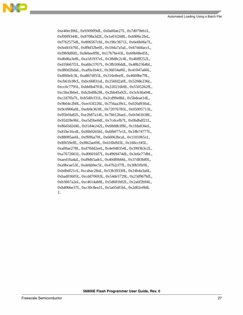
CRC32 Tableconst unsigned long crc32table[256] = {
0x00000000L, 0x77073096L, 0xee0e612cL, 0x990951baL,0x076dc419L, 0x706af48fL, 0xe963a535L, 0x9e6495a3L,0x0edb8832L, 0x79dcb8a4L, 0xe0d5e91eL, 0x97d2d988L,0x09b64c2bL, 0x7eb17cbdL, 0xe7b82d07L, 0x90bf1d91L,0x1db71064L, 0x6ab020f2L, 0xf3b97148L, 0x84be41deL,0x1adad47dL, 0x6ddde4ebL, 0xf4d4b551L, 0x83d385c7L,0x136c9856L, 0x646ba8c0L, 0xfd62f97aL, 0x8a65c9ecL,0x14015c4fL, 0x63066cd9L, 0xfa0f3d63L, 0x8d080df5L,0x3b6e20c8L, 0x4c69105eL, 0xd56041e4L, 0xa2677172L,0x3c03e4d1L, 0x4b04d447L, 0xd20d85fdL, 0xa50ab56bL,
0x35b5a8faL, 0x42b2986cL, 0xdbbbc9d6L, 0xacbcf940L,0x32d86ce3L, 0x45df5c75L, 0xdcd60dcfL, 0xabd13d59L,0x26d930acL, 0x51de003aL, 0xc8d75180L, 0xbfd06116L,0x21b4f4b5L, 0x56b3c423L, 0xcfba9599L, 0xb8bda50fL,0x2802b89eL, 0x5f058808L, 0xc60cd9b2L, 0xb10be924L,0x2f6f7c87L, 0x58684c11L, 0xc1611dabL, 0xb6662d3dL,0x76dc4190L, 0x01db7106L, 0x98d220bcL, 0xefd5102aL,0x71b18589L, 0x06b6b51fL, 0x9fbfe4a5L, 0xe8b8d433L,0x7807c9a2L, 0x0f00f934L, 0x9609a88eL, 0xe10e9818L,0x7f6a0dbbL, 0x086d3d2dL, 0x91646c97L, 0xe6635c01L,0x6b6b51f4L, 0x1c6c6162L, 0x856530d8L, 0xf262004eL,0x6c0695edL, 0x1b01a57bL, 0x8208f4c1L, 0xf50fc457L,0x65b0d9c6L, 0x12b7e950L, 0x8bbeb8eaL, 0xfcb9887cL,0x62dd1ddfL, 0x15da2d49L, 0x8cd37cf3L, 0xfbd44c65L,0x4db26158L, 0x3ab551ceL, 0xa3bc0074L, 0xd4bb30e2L,0x4adfa541L, 0x3dd895d7L, 0xa4d1c46dL, 0xd3d6f4fbL,0x4369e96aL, 0x346ed9fcL, 0xad678846L, 0xda60b8d0L,0x44042d73L, 0x33031de5L, 0xaa0a4c5fL, 0xdd0d7cc9L,0x5005713cL, 0x270241aaL, 0xbe0b1010L, 0xc90c2086L,0x5768b525L, 0x206f85b3L, 0xb966d409L, 0xce61e49fL,0x5edef90eL, 0x29d9c998L, 0xb0d09822L, 0xc7d7a8b4L,0x59b33d17L, 0x2eb40d81L, 0xb7bd5c3bL, 0xc0ba6cadL,0xedb88320L, 0x9abfb3b6L, 0x03b6e20cL, 0x74b1d29aL,0xead54739L, 0x9dd277afL, 0x04db2615L, 0x73dc1683L,0xe3630b12L, 0x94643b84L, 0x0d6d6a3eL, 0x7a6a5aa8L,
Automated Loading Using a Batch File
56800E Flash Programmer User Guide, Rev. 0
Freescale Semiconductor 27
0xe40ecf0bL, 0x9309ff9dL, 0x0a00ae27L, 0x7d079eb1L,0xf00f9344L, 0x8708a3d2L, 0x1e01f268L, 0x6906c2feL,0xf762575dL, 0x806567cbL, 0x196c3671L, 0x6e6b06e7L,0xfed41b76L, 0x89d32be0L, 0x10da7a5aL, 0x67dd4accL,0xf9b9df6fL, 0x8ebeeff9L, 0x17b7be43L, 0x60b08ed5L,0xd6d6a3e8L, 0xa1d1937eL, 0x38d8c2c4L, 0x4fdff252L,0xd1bb67f1L, 0xa6bc5767L, 0x3fb506ddL, 0x48b2364bL,0xd80d2bdaL, 0xaf0a1b4cL, 0x36034af6L, 0x41047a60L,0xdf60efc3L, 0xa867df55L, 0x316e8eefL, 0x4669be79L,0xcb61b38cL, 0xbc66831aL, 0x256fd2a0L, 0x5268e236L,0xcc0c7795L, 0xbb0b4703L, 0x220216b9L, 0x5505262fL,0xc5ba3bbeL, 0xb2bd0b28L, 0x2bb45a92L, 0x5cb36a04L,0xc2d7ffa7L, 0xb5d0cf31L, 0x2cd99e8bL, 0x5bdeae1dL,0x9b64c2b0L, 0xec63f226L, 0x756aa39cL, 0x026d930aL,0x9c0906a9L, 0xeb0e363fL, 0x72076785L, 0x05005713L,0x95bf4a82L, 0xe2b87a14L, 0x7bb12baeL, 0x0cb61b38L,0x92d28e9bL, 0xe5d5be0dL, 0x7cdcefb7L, 0x0bdbdf21L,0x86d3d2d4L, 0xf1d4e242L, 0x68ddb3f8L, 0x1fda836eL,0x81be16cdL, 0xf6b9265bL, 0x6fb077e1L, 0x18b74777L,0x88085ae6L, 0xff0f6a70L, 0x66063bcaL, 0x11010b5cL,0x8f659effL, 0xf862ae69L, 0x616bffd3L, 0x166ccf45L,0xa00ae278L, 0xd70dd2eeL, 0x4e048354L, 0x3903b3c2L,0xa7672661L, 0xd06016f7L, 0x4969474dL, 0x3e6e77dbL,0xaed16a4aL, 0xd9d65adcL, 0x40df0b66L, 0x37d83bf0L,0xa9bcae53L, 0xdebb9ec5L, 0x47b2cf7fL, 0x30b5ffe9L,0xbdbdf21cL, 0xcabac28aL, 0x53b39330L, 0x24b4a3a6L,0xbad03605L, 0xcdd70693L, 0x54de5729L, 0x23d967bfL,0xb3667a2eL, 0xc4614ab8L, 0x5d681b02L, 0x2a6f2b94L,0xb40bbe37L, 0xc30c8ea1L, 0x5a05df1bL, 0x2d02ef8dL};

56800E Flash Programmer User Guide, Rev. 0
28 Freescale Semiconductor
Appendix C Configuration FileThe configuration file format matches the Metrowerks CodeWarrior interface. The file is simply a test file describing how programmers should communicate with the device, and how the device is physically constructed. The file allows a comment (‘#’) character. The following options are allowed in the configuration file. Their behavior may be different for the Metrowerks CodeWarrior tool, especially foroptions ignored by this tool.
:
Table C-1 Configuration File Command Description Default
set_hfmclkd <divisor> Value for HFM clock divisor register 0x14set_hfm_base <address> Base address of the HFM peripheral 0xFFF400add_hfm_unit <start> <end> <bank><# of sectors> <page size> <pgm><boot> <interleaved>
Definition of a flash unit, see below for more information N/A
set_hfm_config_base <address> Address of the HFM configuration area 0xFFF7
set_hfm_programmer_base <address> Address of the PRAM area 0x2F800
set_hfm_verify_program <0/1> Verify every word that is programmed (slow)
0
set_hfm_verify_erase <0/1> Verify erases are completed by reading back the erased unit/page (slow)
0
unlock_flash_on_connect <0/1>Performs a recovery when theprogrammer connects to the deviceregardless of/recover switch
0
set_hfm_erase_mode <all|unit|page>
‘all ’ will erase the entire device when programming. Unit will only erase units to be programmed to, and page will erase only pages to be programmed
Unit
writepmem16 <addr> <value>Writes a 16-bit value to an address inprogram memory when the device is sent into debug mode
N/A
writexmem16 <addr> <value>Writes a 16-bit value to an address in data memory when the device is sent into debug mode
N/A
writereg <reg> <value> Writes a register when the device is sent into debug mode N/A
target_code_sets_hfmclkd Ignored N/Aset_hfm_prog_buffer_base <address> Ignored N/Aset_hfm_prog_buffer_size <value> Ignored N/A

Automated Loading Using a Batch File
56800E Flash Programmer User Guide, Rev. 0
Freescale Semiconductor 29
The parameters of the add_hfm_unit command have the following meanings:
<start> Address of the first location belonging to the flash unit <end> Address of the last location belonging to the flash unit <bank> Selection of bank of HFM registers (see HFM documentation for details) <# of sectors> Number of sectors of the unit (see HFM documentation for details) <page size> Size of flash unit page (see HFM documentation for details) <pgm> Data Memory (=0) or Program memory (=1) <interleaved> Normal flash (=0) or 2 flash blocks interleaved at even/odd address (=1)
Important:
Improper definitions for add_hfm_unit can cause unpredictable programming results. Additionally, specifying an incorrect value for set_hfmclkd may cause permanent damage to the HFM, preventing any future programming of the device.
An example of a Flash configuration file is illustrated in Figure C-1.
Figure C-1 Flash Configuration File Sample
When the S-record file specifies data to be written to a Flash location outside any of the units, the error message, Data @ 0x<address> ignored, is generated (unless the silent mode has been activated. Please see Section 2.1.1.15 for details.
The following is a list of supported registers names for the writereg command: X0, Y0, Y1, A0, A1, A2, B0, B1, B2, C0, C1, C2, D0, D1, D2, OMR, SR, LA, LC, HWS0, HWS1, SP, N3, M01, N, R0, R1, R2, R3, R4, R5, SHM01, SHN, SHR0, SHR1, PC.
set_hfmclkd 0x27 set_hfm_base 0xF400 set_hfm_config_base 0x1FF7 set_hfm_programmer_base 0x8700 # shared p-ram add_hfm_unit 0x0000 0x1FFF 0 16 256 1 0 0

How to Reach Us:
USA/Europe/Locations Not Listed:Freescale Semiconductor Literature Distribution Center P.O. Box 5405 Denver, Colorado 80217 1-800-521-6274 or 480-768-2130
Japan:Freescale Semiconductor Japan Ltd. Technical Information Center 3-20-1, Minami-Azabu, Minato-ku Tokyo 106-8573, Japan 81-3-3440-3569
Asia/Pacific:Freescale Semiconductor Hong Kong Ltd. 2 Dai King Street Tai Po Industrial Estate Tai Po, N.T., Hong Kong 852-26668334
Home Page:www.freescale.com
Freescale™ and the Freescale logo are trademarks of Freescale Semiconductor, Inc. All other product or service names are the property of their respective owners.
© Freescale Semiconductor, Inc. 2005
56800EFPUGRev. 009/2005
Information in this document is provided solely to enable system and software implementers to use Freescale Semiconductor products. There are no express or implied copyright licenses granted hereunder to design or fabricate any integrated circuits or integrated circuits based on the information in this document.Freescale Semiconductor reserves the right to make changes without further notice to any products herein. Freescale Semiconductor makes no warranty, representation or guarantee regarding the suitability of its products for any particular purpose, nor does Freescale Semiconductor assume any liability arising out of the application or use of any product or circuit, and specifically disclaims any and all liability, including without limitation consequential or incidental damages. “Typical” parameters that may be provided in Freescale Semiconductor data sheets and/or specifications can and do vary in different applications and actual performance may vary over time. All operating parameters, including “Typicals,” must be validated for each customer application by customer’s technical experts. Freescale Semiconductor does not convey any license under its patent rights nor the rights of others. Freescale Semiconductor products are not designed, intended, or authorized for use as components in systems intended for surgical implant into the body, or other applications intended to support or sustain life, or for any other application in which the failure of the Freescale Semiconductor product could create a situation where personal injury or death may occur. Should Buyer purchase or use Freescale Semiconductor products for any such unintended or unauthorized application, Buyer shall indemnify and hold Freescale Semiconductor and its officers, employees, subsidiaries, affiliates, and distributors harmless against all claims, costs, damages, and expenses, and reasonable attorney fees arising out of, directly or indirectly, any claim of personal injury or death associated with such unintended or unauthorized use, even if such claim alleges that Freescale Semiconductor was negligent regarding the design or manufacture of the part.
Learn More: For more information about Freescale products, please visit www.freescale.com