Embed Size (px)
Citation preview

EUROTHERMDRIVES
590+ SeriesDC Digital Converter
Product ManualHA466461U002 Issue 1
Copyright Eurotherm Drives Limited 2001
All rights strictly reserved. No part of this document may be stored in a retrieval system, or transmitted in any form orby any means to persons not employed by a Eurotherm group company without written permission from EurothermDrives Ltd.
Although every effort has been taken to ensure the accuracy of this document it may be necessary, without notice, tomake amendments or correct omissions. Eurotherm Drives cannot accept responsibility for damage, injury, or expensesresulting therefrom.
Compatible with Version 5.x Software

Cont.2
WARRANTYEurotherm Drives warrants the goods against defects in design, materials and workmanship
for the period of 12 months from the date of delivery on the termsdetailed in Eurotherm Drives Standard Conditions of Sale IA058393C.
Eurotherm Drives reserves the right to change the content and product specification without notice.

Cont.3
RequirementsIMPORTANT: Please read this information BEFORE installing the equipment.
Intended UsersThis manual is to be made available to all persons who are required to install, configure orservice equipment described herein, or any other associated operation.
The information given is intended to highlight safety issues, and to enable the user to obtainmaximum benefit from the equipment.
Complete the following table for future reference detailing how the unit is to be installed andused.
INSTALLATION DETAILS
Serial Number(see product label)
Where installed(for your owninformation)
Unit used as a:(refer to Certificationfor the Converter)
Component Relevant Apparatus
Unit fitted: Wall-mounted Enclosure
Application AreaThe equipment described is intended for industrial (non consumer) motor speed control utilisingdc shunt machines.
PersonnelInstallation, operation and maintenance of the equipment should be carried out by qualifiedpersonnel. A qualified person is someone who is technically competent and familiar with allsafety information and established safety practices; with the installation process, operation andmaintenance of this equipment; and with all the hazards involved.
!Safety Information

Cont.4
Hazards
WARNING! This equipment can endanger life through rotating machinery and high voltages.
Failure to observe the following will constitute an ELECTRICAL SHOCK HAZARD.This is a product of the restricted sales distribution class according to IEC 61800-3.
In a domestic environment this product may cause radio interference in which case theuser may be required to take adequate measures.
This product is designated as “professional equipment” as defined in EN61000-3-2.Permission of the supply authority shall be obtained before connection to the low
voltage supply.
• The equipment must be permanently earthed due to the high earth leakage current.
• The drive motor must be connected to an appropriate safety earth.
• Before working on the equipment, ensure isolation of the mains supply from terminals L1,L2 and L3.
• Never perform high voltage resistance checks on the wiring without first disconnecting thedrive from the circuit being tested.
• When replacing a drive in an application and before returning to use, it is essential that alluser defined parameters for the product’s operation are correctly installed.
• This equipment contains electrostatic discharge (ESD) sensitive parts. Observe staticcontrol precautions when handling, installing and servicing this product.
IMPORTANT: Metal parts may reach a temperature of 90 degrees centigrade in operation.
Application RiskThe specifications, processes and circuitry described herein are for guidance only and may needto be adapted to the user’s specific application.
Eurotherm Drives does not guarantee the suitability of the equipment described in this Manualfor individual applications.
Risk AssessmentUnder fault conditions, power loss or other operating conditions not intended, the equipmentmay not operate as specified. In particular:
• The motor speed may not be controlled
• The direction of rotation of the motor may not be controlled
• The motor may be energised
Guards The user must provide guarding and /or additional safety systems to prevent risk of injury andelectric shock.
Protective Insulation• All control and signal terminals are SELV, i.e. protected by double insulation. Ensure all
wiring is rated for the highest system voltage.
Note: Thermal sensors contained within the motor must be double insulated.
• All exposed metalwork in the Converter is protected by basic insulation and bonding to asafety earth.
RCDs These are not recommended for use with this product but ,where their use is mandatory, onlyType B RCDs should be used.
!Safety Information
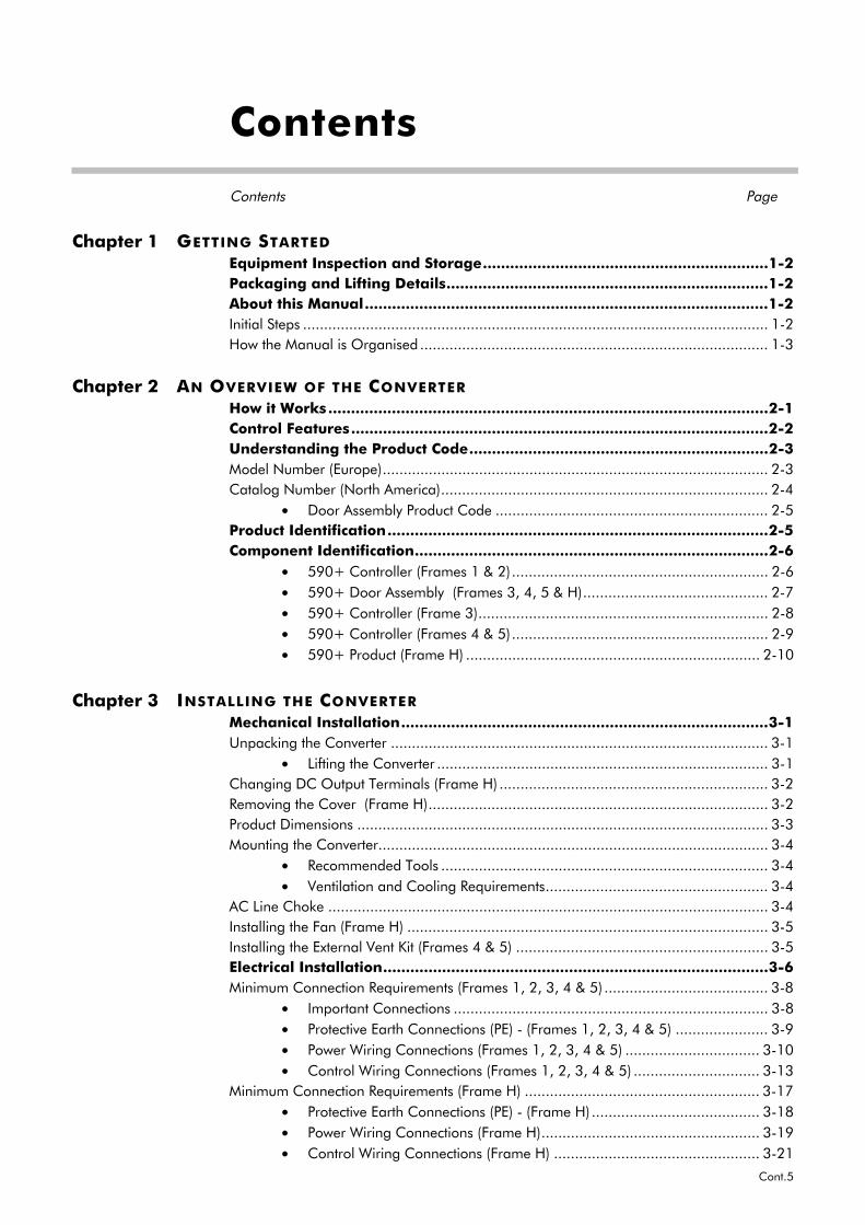
Contents
Contents Page
Cont.5
Chapter 1 GETTING STARTED
Equipment Inspection and Storage...............................................................1-2Packaging and Lifting Details.......................................................................1-2About this Manual.........................................................................................1-2Initial Steps ............................................................................................................... 1-2How the Manual is Organised ................................................................................... 1-3
Chapter 2 AN OVERVIEW OF THE CONVERTER
How it Works .................................................................................................2-1Control Features............................................................................................2-2Understanding the Product Code..................................................................2-3Model Number (Europe)............................................................................................ 2-3Catalog Number (North America).............................................................................. 2-4
• Door Assembly Product Code ................................................................. 2-5Product Identification....................................................................................2-5Component Identification..............................................................................2-6
• 590+ Controller (Frames 1 & 2)............................................................. 2-6• 590+ Door Assembly (Frames 3, 4, 5 & H)............................................ 2-7• 590+ Controller (Frame 3)..................................................................... 2-8• 590+ Controller (Frames 4 & 5)............................................................. 2-9• 590+ Product (Frame H) ...................................................................... 2-10
Chapter 3 INSTALLING THE CONVERTER
Mechanical Installation.................................................................................3-1Unpacking the Converter .......................................................................................... 3-1
• Lifting the Converter ............................................................................... 3-1Changing DC Output Terminals (Frame H) ................................................................ 3-2Removing the Cover (Frame H)................................................................................. 3-2Product Dimensions .................................................................................................. 3-3Mounting the Converter............................................................................................. 3-4
• Recommended Tools .............................................................................. 3-4• Ventilation and Cooling Requirements..................................................... 3-4
AC Line Choke ......................................................................................................... 3-4Installing the Fan (Frame H) ...................................................................................... 3-5Installing the External Vent Kit (Frames 4 & 5) ............................................................ 3-5Electrical Installation.....................................................................................3-6Minimum Connection Requirements (Frames 1, 2, 3, 4 & 5) ....................................... 3-8
• Important Connections ........................................................................... 3-8• Protective Earth Connections (PE) - (Frames 1, 2, 3, 4 & 5) ...................... 3-9• Power Wiring Connections (Frames 1, 2, 3, 4 & 5) ................................ 3-10• Control Wiring Connections (Frames 1, 2, 3, 4 & 5) .............................. 3-13
Minimum Connection Requirements (Frame H) ........................................................ 3-17• Protective Earth Connections (PE) - (Frame H) ........................................ 3-18• Power Wiring Connections (Frame H).................................................... 3-19• Control Wiring Connections (Frame H) ................................................. 3-21
Contents
Contents Page
Cont.6
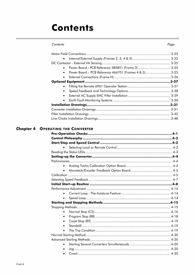
Motor Field Connections ......................................................................................... 3-22• Internal/External Supply (Frames 2, 3, 4 & 5) ........................................ 3-22
DC Contactor - External VA Sensing ........................................................................ 3-25• Power Board - PCB Reference 385851 (Frame 3) .................................. 3-25• Power Board – PCB Reference 466701 (Frames 4 & 5) .......................... 3-25• External Connections (Frame H)............................................................ 3-26
Optional Equipment ....................................................................................3-27• Fitting the Remote 6901 Operator Station ............................................. 3-27• Speed Feedback and Technology Options............................................. 3-28• External AC Supply EMC Filter Installation ............................................. 3-29• Earth Fault Monitoring Systems ............................................................. 3-30
Installation Drawings..................................................................................3-31Converter Installation Drawings ............................................................................... 3-31Filter Installation Drawings ...................................................................................... 3-42Line Choke Installation Drawings............................................................................. 3-48
Chapter 4 OPERATING THE CONVERTER
Pre-Operation Checks...................................................................................4-1Control Philosophy ........................................................................................4-2Start/Stop and Speed Control .......................................................................4-2
• Selecting Local or Remote Control........................................................... 4-3Reading the Status LEDs ............................................................................................ 4-3Setting-up the Converter...............................................................................4-4Preliminaries............................................................................................................. 4-4
• Analog Tacho Calibration Option Board ................................................. 4-4• Microtach/Encoder Feedback Option Board ............................................ 4-5
Calibration ............................................................................................................... 4-5Selecting Speed Feedback ......................................................................................... 4-7Initial Start-up Routine .................................................................................4-8Performance Adjustment ......................................................................................... 4-14
• Current Loop - The Autotune Feature .................................................... 4-14• Speed Loop.......................................................................................... 4-14
Starting and Stopping Methods ..................................................................4-15Stopping Methods ................................................................................................... 4-15
• Normal Stop (C3)................................................................................. 4-16• Program Stop (B8)................................................................................ 4-18• Coast Stop (B9) .................................................................................... 4-19• Standstill .............................................................................................. 4-19• The Trip Condition ............................................................................... 4-19
Normal Starting Method.......................................................................................... 4-20Advanced Starting Methods ..................................................................................... 4-20
• Starting Several Converters Simultaneously ........................................... 4-20• Jog ...................................................................................................... 4-20• Crawl................................................................................................... 4-20
Contents
Contents Page
Cont.7
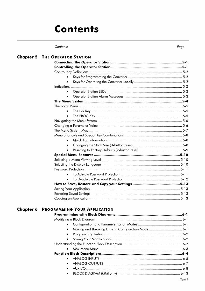
Chapter 5 THE OPERATOR STATION
Connecting the Operator Station ..................................................................5-1Controlling the Operator Station ..................................................................5-1Control Key Definitions.............................................................................................. 5-2
• Keys for Programming the Converter ...................................................... 5-2• Keys for Operating the Converter Locally ................................................ 5-2
Indications ................................................................................................................ 5-3• Operator Station LEDs ............................................................................ 5-3• Operator Station Alarm Messages .......................................................... 5-3
The Menu System ..........................................................................................5-4The Local Menu ........................................................................................................ 5-5
• The L/R Key............................................................................................ 5-5• The PROG Key ....................................................................................... 5-5
Navigating the Menu System ..................................................................................... 5-6Changing a Parameter Value .................................................................................... 5-6The Menu System Map .............................................................................................. 5-7Menu Shortcuts and Special Key Combinations .......................................................... 5-8
• Quick Tag Information ........................................................................... 5-8• Changing the Stack Size (3-button reset) ................................................. 5-8• Resetting to Factory Defaults (2-button reset) ........................................... 5-9
Special Menu Features ................................................................................5-10Selecting a Menu Viewing Level ............................................................................... 5-10Selecting the Display Language ............................................................................... 5-10Password Protection ................................................................................................ 5-11
• To Activate Password Protection ............................................................ 5-11• To Deactivate Password Protection ........................................................ 5-12
How to Save, Restore and Copy your Settings ............................................5-13Saving Your Application .......................................................................................... 5-13Restoring Saved Settings.......................................................................................... 5-13Copying an Application........................................................................................... 5-13
Chapter 6 PROGRAMMING YOUR APPLICATION
Programming with Block Diagrams..............................................................6-1Modifying a Block Diagram....................................................................................... 6-1
• Configuration and Parameterisation Modes ............................................ 6-1• Making and Breaking Links in Configuration Mode ................................. 6-1• Programming Rules ................................................................................ 6-2• Saving Your Modifications ...................................................................... 6-2
Understanding the Function Block Description............................................................ 6-2• MMI Menu Maps .................................................................................... 6-3
Function Block Descriptions...........................................................................6-4• ANALOG INPUTS................................................................................... 6-5• ANALOG OUTPUTS............................................................................... 6-7• AUX I/O................................................................................................. 6-8• BLOCK DIAGRAM (MMI only) ............................................................... 6-13
Contents
Contents Page
Cont.8
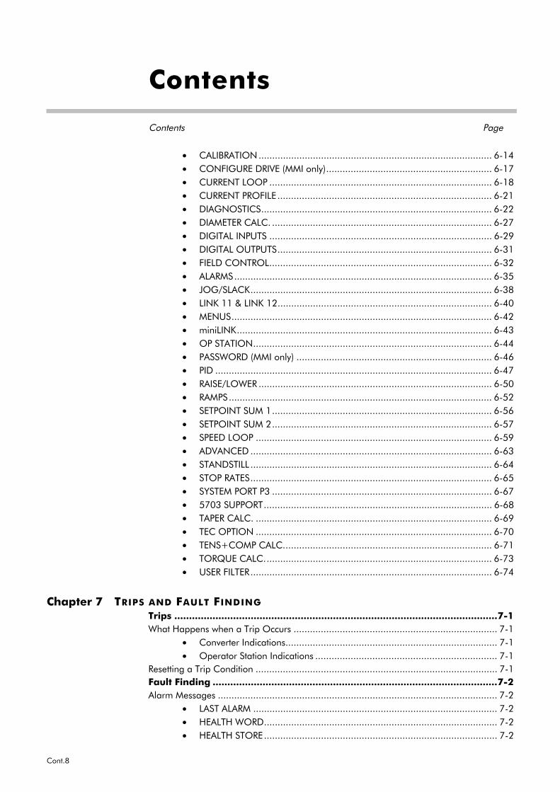
• CALIBRATION...................................................................................... 6-14• CONFIGURE DRIVE (MMI only)............................................................. 6-17• CURRENT LOOP .................................................................................. 6-18• CURRENT PROFILE ............................................................................... 6-21• DIAGNOSTICS..................................................................................... 6-22• DIAMETER CALC. ................................................................................. 6-27• DIGITAL INPUTS .................................................................................. 6-29• DIGITAL OUTPUTS............................................................................... 6-31• FIELD CONTROL.................................................................................. 6-32• ALARMS............................................................................................... 6-35• JOG/SLACK......................................................................................... 6-38• LINK 11 & LINK 12............................................................................... 6-40• MENUS................................................................................................ 6-42• miniLINK.............................................................................................. 6-43• OP STATION........................................................................................ 6-44• PASSWORD (MMI only) ........................................................................ 6-46• PID ...................................................................................................... 6-47• RAISE/LOWER ...................................................................................... 6-50• RAMPS................................................................................................. 6-52• SETPOINT SUM 1................................................................................. 6-56• SETPOINT SUM 2................................................................................. 6-57• SPEED LOOP ....................................................................................... 6-59• ADVANCED ......................................................................................... 6-63• STANDSTILL ......................................................................................... 6-64• STOP RATES......................................................................................... 6-65• SYSTEM PORT P3 ................................................................................. 6-67• 5703 SUPPORT.................................................................................... 6-68• TAPER CALC. ....................................................................................... 6-69• TEC OPTION ....................................................................................... 6-70• TENS+COMP CALC............................................................................. 6-71• TORQUE CALC.................................................................................... 6-73• USER FILTER......................................................................................... 6-74
Chapter 7 TRIPS AND FAULT FINDING
Trips ..............................................................................................................7-1What Happens when a Trip Occurs ........................................................................... 7-1
• Converter Indications.............................................................................. 7-1• Operator Station Indications ................................................................... 7-1
Resetting a Trip Condition ......................................................................................... 7-1Fault Finding .................................................................................................7-2Alarm Messages ....................................................................................................... 7-2
• LAST ALARM .......................................................................................... 7-2• HEALTH WORD...................................................................................... 7-2• HEALTH STORE...................................................................................... 7-2
Contents
Contents Page
Cont.9
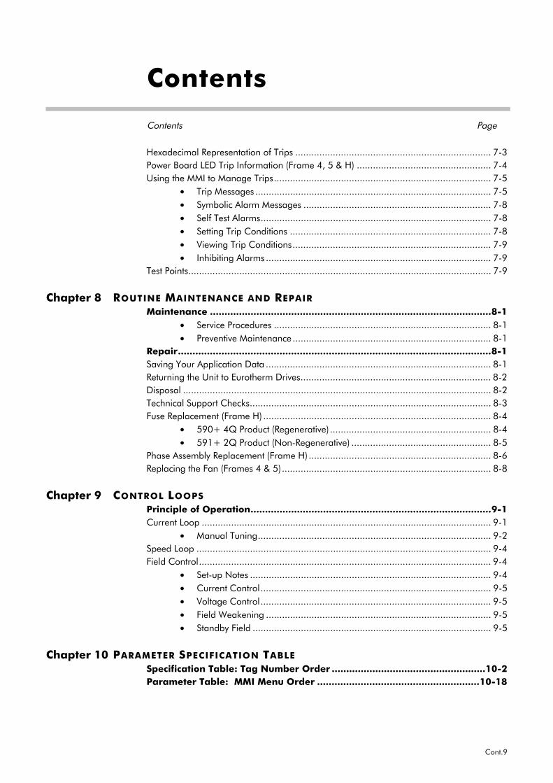
Hexadecimal Representation of Trips ......................................................................... 7-3Power Board LED Trip Information (Frame 4, 5 & H) .................................................. 7-4Using the MMI to Manage Trips................................................................................. 7-5
• Trip Messages ........................................................................................ 7-5• Symbolic Alarm Messages ...................................................................... 7-8• Self Test Alarms...................................................................................... 7-8• Setting Trip Conditions ........................................................................... 7-8• Viewing Trip Conditions.......................................................................... 7-9• Inhibiting Alarms .................................................................................... 7-9
Test Points................................................................................................................. 7-9
Chapter 8 ROUTINE MAINTENANCE AND REPAIR
Maintenance .................................................................................................8-1• Service Procedures ................................................................................. 8-1• Preventive Maintenance .......................................................................... 8-1
Repair............................................................................................................8-1Saving Your Application Data .................................................................................... 8-1Returning the Unit to Eurotherm Drives....................................................................... 8-2Disposal ................................................................................................................... 8-2Technical Support Checks.......................................................................................... 8-3Fuse Replacement (Frame H) ..................................................................................... 8-4
• 590+ 4Q Product (Regenerative) ............................................................ 8-4• 591+ 2Q Product (Non-Regenerative) .................................................... 8-5
Phase Assembly Replacement (Frame H) .................................................................... 8-6Replacing the Fan (Frames 4 & 5).............................................................................. 8-8
Chapter 9 CONTROL LOOPS
Principle of Operation...................................................................................9-1Current Loop ............................................................................................................ 9-1
• Manual Tuning....................................................................................... 9-2Speed Loop .............................................................................................................. 9-4Field Control............................................................................................................. 9-4
• Set-up Notes .......................................................................................... 9-4• Current Control...................................................................................... 9-5• Voltage Control...................................................................................... 9-5• Field Weakening .................................................................................... 9-5• Standby Field ......................................................................................... 9-5
Chapter 10 PARAMETER SPECIFICATION TABLE
Specification Table: Tag Number Order .....................................................10-2Parameter Table: MMI Menu Order ........................................................10-18
Contents
Contents Page
Cont.10
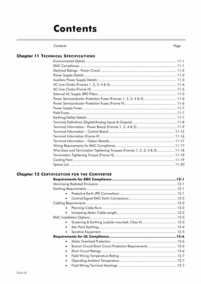
Chapter 11 TECHNICAL SPECIFICATIONS
Environmental Details ............................................................................................. 11-1EMC Compliance.................................................................................................... 11-1Electrical Ratings - Power Circuit .............................................................................. 11-2Power Supply Details ............................................................................................... 11-3Auxiliary Power Supply Details ................................................................................. 11-3AC Line Choke (Frames 1, 2, 3, 4 & 5) .................................................................... 11-4AC Line Choke (Frame H) ....................................................................................... 11-5External AC Supply (RFI) Filters ................................................................................ 11-5Power Semiconductor Protection Fuses (Frames 1, 2, 3, 4 & 5) ................................. 11-6Power Semiconductor Protection Fuses (Frame H)..................................................... 11-6Power Supply Fuses................................................................................................. 11-7Field Fuses.............................................................................................................. 11-7Earthing/Safety Details ............................................................................................ 11-7Terminal Definitions (Digital/Analog Inputs & Outputs) ............................................. 11-8Terminal Information - Power Board (Frames 1, 2, 4 & 5)......................................... 11-9Terminal Information – Control Board ................................................................... 11-12Terminal Information (Frame H) ............................................................................ 11-16Terminal Information – Option Boards................................................................... 11-17Wiring Requirements for EMC Compliance ............................................................ 11-17Wire Sizes and Termination Tightening Torques (Frames 1, 2, 3, 4 & 5).................. 11-18Termination Tightening Torque (Frame H).............................................................. 11-19Cooling Fans ........................................................................................................ 11-19Spares List ............................................................................................................ 11-20
Chapter 12 CERTIFICATION FOR THE CONVERTER
Requirements for EMC Compliance .............................................................12-1Minimising Radiated Emissions ................................................................................ 12-1Earthing Requirements ............................................................................................ 12-1
• Protective Earth (PE) Connections .......................................................... 12-1• Control/Signal EMC Earth Connections................................................. 12-2
Cabling Requirements ............................................................................................. 12-2• Planning Cable Runs ............................................................................ 12-2• Increasing Motor Cable Length ............................................................. 12-2
EMC Installation Options......................................................................................... 12-3• Screening & Earthing (cubicle mounted, Class A) ................................... 12-3• Star Point Earthing................................................................................ 12-4• Sensitive Equipment.............................................................................. 12-5
Requirements for UL Compliance................................................................12-6• Motor Overload Protection.................................................................... 12-6• Branch Circuit/Short Circuit Protection Requirements ............................. 12-6• Short Circuit Ratings ............................................................................. 12-6• Field Wiring Temperature Rating........................................................... 12-7• Operating Ambient Temperature .......................................................... 12-7• Field Wiring Terminal Markings ............................................................ 12-7
Contents
Contents Page
Cont.11
• Power and Control Field Wiring Terminals............................................. 12-7• Field Grounding Terminals ................................................................... 12-7• Field Terminal Kits ................................................................................ 12-7• Fuse Replacement Information.............................................................. 12-7
Recommended Wire Sizes (Frames 1, 2, 4 & 5) ........................................................ 12-8Recommended Wire Sizes (Frame H) ....................................................................... 12-8European Directives and the CE Mark ........................................................12-9CE Marking for Low Voltage Directive ...................................................................... 12-9CE Marking for EMC - Who is Responsible? ............................................................. 12-9
• Legal Requirements for CE Marking .................................................... 12-10• Applying for CE Marking for EMC....................................................... 12-10
Which Standards Apply? ....................................................................................... 12-11• Basic and Generic Standards.............................................................. 12-11
Certificates............................................................................................................ 12-13
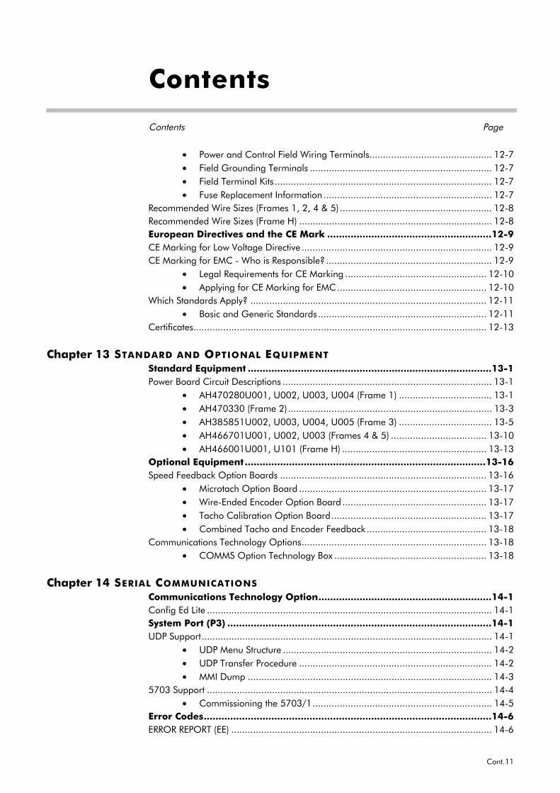
Chapter 13 STANDARD AND OPTIONAL EQUIPMENT
Standard Equipment ...................................................................................13-1Power Board Circuit Descriptions ............................................................................. 13-1
• AH470280U001, U002, U003, U004 (Frame 1) .................................. 13-1• AH470330 (Frame 2)........................................................................... 13-3• AH385851U002, U003, U004, U005 (Frame 3) .................................. 13-5• AH466701U001, U002, U003 (Frames 4 & 5) ................................... 13-10• AH466001U001, U101 (Frame H) ..................................................... 13-13
Optional Equipment ..................................................................................13-16Speed Feedback Option Boards ............................................................................ 13-16
• Microtach Option Board ..................................................................... 13-17• Wire-Ended Encoder Option Board ..................................................... 13-17• Tacho Calibration Option Board......................................................... 13-17• Combined Tacho and Encoder Feedback ............................................ 13-18
Communications Technology Options.................................................................... 13-18• COMMS Option Technology Box ........................................................ 13-18
Chapter 14 SERIAL COMMUNICATIONS
Communications Technology Option...........................................................14-1Config Ed Lite ......................................................................................................... 14-1System Port (P3) ..........................................................................................14-1UDP Support........................................................................................................... 14-1
• UDP Menu Structure ............................................................................. 14-2• UDP Transfer Procedure ....................................................................... 14-2• MMI Dump .......................................................................................... 14-3
5703 Support ......................................................................................................... 14-4• Commissioning the 5703/1.................................................................. 14-5
Error Codes..................................................................................................14-6ERROR REPORT (EE) ................................................................................................ 14-6

Contents
Contents Page
Cont.12
Chapter 15 THE DEFAULT APPLICATION
Block Diagrams...........................................................................................15-1Programming Block Diagram - Sheet 1.................................................................... 15-3Programming Block Diagram - Sheet 2.................................................................... 15-4Main Block Diagram ............................................................................................... 15-5Field Control Block Diagram ................................................................................... 15-6Start/Healthy Logic Block Diagram .......................................................................... 15-7Functional Block Diagram ....................................................................................... 15-8
Getting Started 1-1
590+ Series DC Digital Converter
1 GETTING STARTEDSystem DesignThe 590+ Series Converter is designed for use in a suitable enclosure, with associated controlequipment. The unit accepts a variety of standard three-phase ac supply voltages depending uponthe model, and is suitable for the powering of DC shunt field and permanent magnet motors,providing controlled dc output voltage and current for armature and field.
All units are designed for simple and economical panel mounting using keyhole slots. Plug-incontrol connectors simplify the fitting and removal of the unit to the panel.
Where possible, standard parts are used throughout the range thereby reducing the variety ofspare parts required to maintain a multi-drive system. For example, the same basic control boardsare used in all types of three-phase armature controller regardless of horsepower or bridgeconfiguration.
The control circuit is totally isolated from the power circuit thus simplifying the interconnectionof controllers within a system and improving operator safety. The coding circuitry adjustsautomatically to accept supply frequencies between 45-65Hz and possesses high immunity tosupply-borne interference. The armature controllers are phase rotation insensitive.
Control and CommunicationsThe Converter is controlled by a 16 bit Microcontroller providing advanced features such as:
• Complex control algorithms which are not achievable by simple analog techniques.
• Software-configurable control circuitry built around standard software blocks.
• Serial link communications with other drives or a PC for advanced process systems.
The Operator Station gives access to parameters, diagnostic messages, trip settings and fullapplication programming.
Regenerative and Non-Regenerative ModelsThe motor armature controllers include both regenerative and non-regenerative models:
• Regenerative controllers consist of two fully-controlled thyristor bridges and a field bridgewith full transient and overload protection, together with sophisticated electronic control ofacceleration and deceleration, speed and torque in both directions of rotation.
• Non-regenerative controllers consist of one fully-controlled thyristor bridge and a fieldbridge with full transient and overload protection, together with its associated electroniccontrol circuitry, and provide accurate speed and/or torque control in one selected directionof rotation.
Field RegulatorA field regulator is fitted as standard. The regulator consists of a full-wave half controlled singlephase thyristor bridge with transient and overload protection. It provides either a fixed voltage orfixed current source, depending upon the selected mode of operation for constant torqueapplications. The field current mode of operation can be further enhanced to provide fieldweakening for drive control motors which require extended speed or constant horsepowercontrol.
1-2 Getting Started
590+ Series DC Digital Converter
Equipment Inspection and Storage• Check for signs of transit damage• Check the product code on the rating label conforms to your requirement.
If the unit is not being installed immediately, store the unit in a well-ventilated place away fromhigh temperatures, humidity, dust, or metal particles.
Refer to Chapter 2: “An Overview of the Converter” to check the rating label/product code.Refer to Chapter 8: “Routine Maintenance and Repair” for information on returning damagedgoods.Refer to Chapter 11: “Technical Specifications” - Environmental Details for the storagetemperature.
Packaging and Lifting Details
Caution The packaging is combustible and, if disposed of in this manner incorrectly, may lead to
the generation of lethal toxic fumes.
Save the packaging in case of return. Improper packaging can result in transit damage.
Use a safe and suitable lifting procedure when moving the drive. Never lift the drive by itsterminal connections.
Prepare a clear, flat surface to receive the drive before attempting to move it. Do not damage anyterminal connections when putting the drive down.
Refer to Chapter 11: “Technical Specifications” - Mechanical Details for unit weights.
About this ManualThis manual is intended for use by the installer, user and programmer of the 590+ SeriesConverter. It assumes a reasonable level of understanding in these three disciplines.
Note: Please read all Safety Information before proceeding with the installation and operationof this unit.
Enter the “Model No” from the rating label into the table at the front of this manual. There isalso a column for you to record your application’s parameter settings in the table in Chapter 10.It is important that you pass this manual on to any new user of this unit.
This manual is for the following models from the 590+ Converter Series:
• Three phase, regenerative, four quadrant armature controllers:590+
• Three phase non-regenerative, two quadrant armature controllers:591+
• 590+ Door
Initial StepsUse the manual to help you plan the following:
InstallationKnow your requirements:
• certification requirements, CE/UL/c-UL conformance
• conformance with local installation requirements
• supply and cabling requirements

Getting Started 1-3
590+ Series DC Digital Converter
OperationKnow your operator:
• how is it to be operated, local and/or remote?
• what level of user is going to operate the unit?
• decide on the best menu level for the Operator Station (where supplied)
Programming (Operator Station or suitable PC programming tool only)Know your application:
• plan your “block diagram programming”
• enter a password to guard against illicit or accidental changes
• learn how to back-up your application data
• customise the Operator Station to the application
How the Manual is OrganisedThe manual is divided into chapters and paragraphs. Page numbering restarts with every chapter,i.e. 5-3 is Chapter 5, page 3.
Application Block DiagramYou will find this at the rear of the manual. The pages unfold to show a complete block diagram,this will become your programming tool as you become more familiar with the software.

1-4 Getting Started
590+ Series DC Digital Converter
An Overview of the Converter 2-1
590+ Series DC Digital Converter
2 AN OVERVIEW OF THE CONVERTER
How it WorksNote: Refer to Chapter 9: “Control Loops” for a more detailed explanation.
In very simple terms, the Converter controls the dc motor with the use of Control Loops - aninner Current Loop and an outer Speed Loop. These control loops can be seen in the ApplicationBlock Diagram. The block diagram shows all the Converter’s software connections.
Using the Operator Station, you can select the control loops to be used by the Converter toprovide either:
• Current Control
• Speed Control (default)
It is usual to supply a Current or Speed Feedback signal to the appropriate loop for moreeffective control of the Converter. Current Feedback sensors are built-in, whereas SpeedFeedback is provided directly from the armature sensing circuit (default), or by tachogenerator,encoder or Microtach connection to the relevant option board.
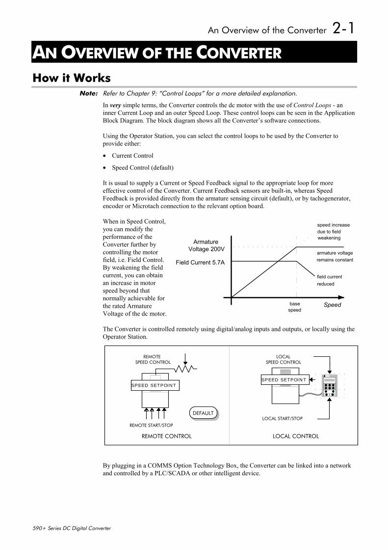
When in Speed Control,you can modify theperformance of theConverter further bycontrolling the motorfield, i.e. Field Control.By weakening the fieldcurrent, you can obtainan increase in motorspeed beyond thatnormally achievable forthe rated ArmatureVoltage of the dc motor.
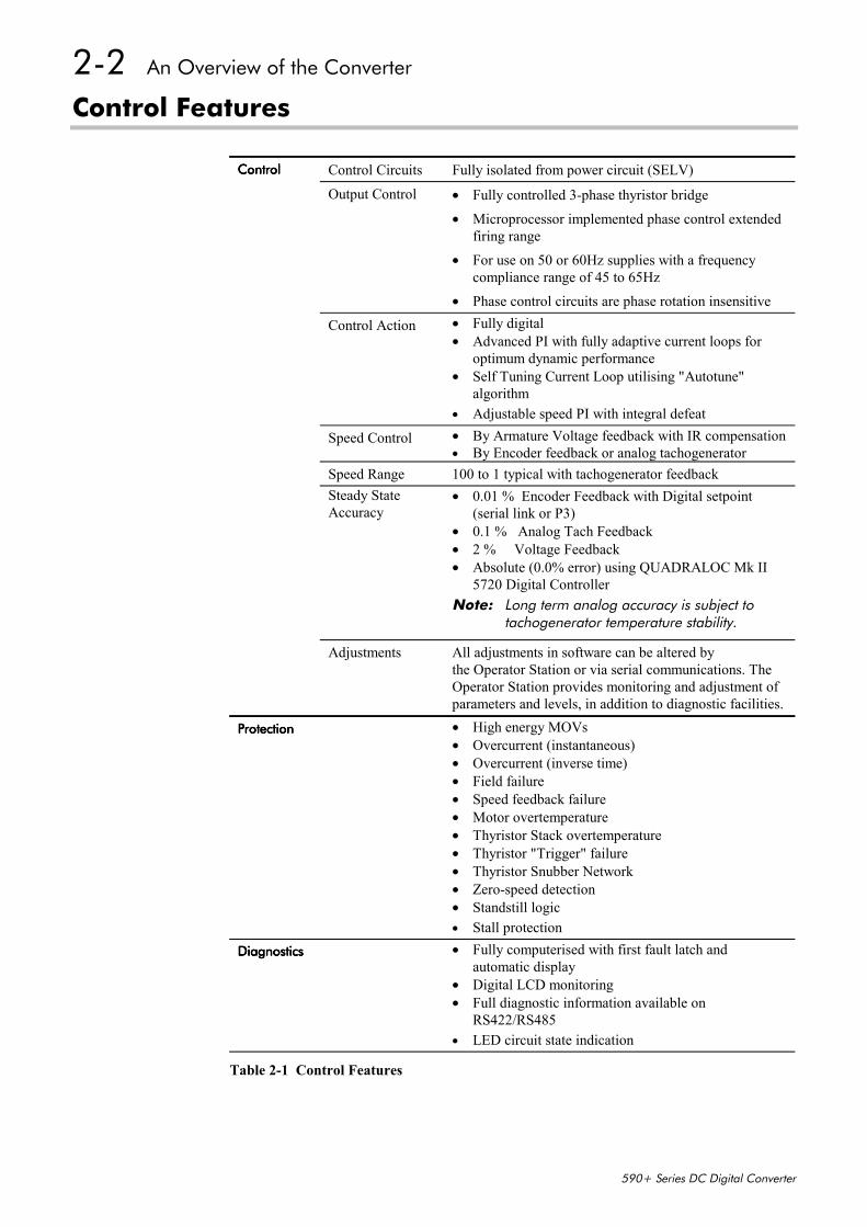
The Converter is controlled remotely using digital/analog inputs and outputs, or locally using theOperator Station.
By plugging in a COMMS Option Technology Box, the Converter can be linked into a networkand controlled by a PLC/SCADA or other intelligent device.
Field Current 5.7A
Voltage 200V
Speed
speed increasedue to fieldweakening
armature voltageremains constant
field currentreduced
basespeed
Armature
REMOTE START/STOP
REMOTE
LOCAL START/STOP
LOCALSPEED CONTROL SPEED CONTROL
DEFAULT
SPEED SETPOINTSPEED SETPOINT
LOCAL CONTROLREMOTE CONTROL
2-2 An Overview of the Converter
590+ Series DC Digital Converter
Control Features
ControlControlControlControl Control Circuits Fully isolated from power circuit (SELV)
Output Control • Fully controlled 3-phase thyristor bridge
• Microprocessor implemented phase control extendedfiring range
• For use on 50 or 60Hz supplies with a frequencycompliance range of 45 to 65Hz
• Phase control circuits are phase rotation insensitive
Control Action • Fully digital• Advanced PI with fully adaptive current loops for
optimum dynamic performance• Self Tuning Current Loop utilising "Autotune"
algorithm• Adjustable speed PI with integral defeat
Speed Control • By Armature Voltage feedback with IR compensation• By Encoder feedback or analog tachogenerator
Speed Range 100 to 1 typical with tachogenerator feedbackSteady StateAccuracy
• 0.01 % Encoder Feedback with Digital setpoint(serial link or P3)
• 0.1 % Analog Tach Feedback• 2 % Voltage Feedback• Absolute (0.0% error) using QUADRALOC Mk II
5720 Digital ControllerNote: Long term analog accuracy is subject to
tachogenerator temperature stability.
Adjustments All adjustments in software can be altered bythe Operator Station or via serial communications. TheOperator Station provides monitoring and adjustment ofparameters and levels, in addition to diagnostic facilities.
ProtectionProtectionProtectionProtection • High energy MOVs• Overcurrent (instantaneous)• Overcurrent (inverse time)• Field failure• Speed feedback failure• Motor overtemperature• Thyristor Stack overtemperature• Thyristor "Trigger" failure• Thyristor Snubber Network• Zero-speed detection• Standstill logic• Stall protection
DiagnosticsDiagnosticsDiagnosticsDiagnostics • Fully computerised with first fault latch andautomatic display
• Digital LCD monitoring• Full diagnostic information available on
RS422/RS485• LED circuit state indication
Table 2-1 Control Features

An Overview of the Converter 2-3
590+ Series DC Digital Converter
Understanding the Product Code
Model Number (Europe)The unit is fully identified using an alphanumeric code which records how the Converter wascalibrated, its various settings when despatched from the factory, and the country of origin.
The Product Code appears as the “Model No”. Each block of the Product Code is identified asbelow:
Model Number (Europe)Model Number (Europe)Model Number (Europe)Model Number (Europe)
BlockBlockBlockBlockNo.No.No.No.
VariableVariableVariableVariable DescriptionDescriptionDescriptionDescription
1 XXXX Generic product
590P : 590+ 4Q DC Drive591P : 590+ 2Q DC Drive
2 XXXX Four digits identifying the maximum dc output current rating that may becalibrated for each size of product:
0015 = 15A (Frame 1)0035 = 35A (Frame 1)
0040 = 40A (Frame 2)0070 = 70A (Frame 2)0110 = 110A (Frame 2)0165 = 165A (Frame 2)
0180 = 180A (Frame 3)0270 = 270A (Frame 3)
0380 = 380A (Frame 4)0500 = 500A (Frame 4)0725 = 725A (Frame 4)0830 = 830A (Frame 4)1580 = 1580A (Frame 5)
1200 = 1200A (Frame H)1700 = 1700A (Frame H)2200 = 2200A (Frame H)2700 = 2700A (Frame H)
3 XXX 3 digits identifying the nominal 3 phase ac power, supply voltage:
220 110 to 220V (±10%) 50/60Hz500 220 to 500V (±10%) 50/60Hz600 500 to 600V (±10%) 50/60Hz (Frame 4 & 5 only)690 500 to 690V (±10%) 50/60Hz (Frame H only)
4 XXXX 4 digits describing the mechanical package including livery and mechanicalpackage style:
First two digits (on the left) Livery00 Standard Eurotherm Livery05 Distributor Livery01-04 and 06-99 Defined customer liveries TBA
Third digit Mechanical Package Style1 Standard (IP20), protected panel mounting4 Panel Mounting IP20 plus Roof Vent Kit
(Frame 4 only)
Fourth digit Operator Station0 No operator station1 Built-in 6901 operator station
5 XX Two characters specifying the user interface language:
UK = EnglishFR = FrenchGR = German (refer to Customer Services)SP = Spanish (refer to Customer Services)IT = Italian (refer to Customer Services)
2-4 An Overview of the Converter
590+ Series DC Digital Converter
Model Number (Europe)Model Number (Europe)Model Number (Europe)Model Number (Europe)
BlockBlockBlockBlockNo.No.No.No.
VariableVariableVariableVariable DescriptionDescriptionDescriptionDescription
6 XXX Up to three characters specifying the feedback option (one must be fitted):
ARM = Armature VoltageAN = Analog TachoENW = Encoder (wire-ended)ENP = Encoder (plastic fibre-optic)ENG = Encoder (glass fibre-optic)
7 XXXXX Up to five characters specifying the 6055 communications Tech Box option:
0 = No Comms option fittedEI00 = EI ASCII/Bisync with hardware implementation 1 (RS485/422)PROF = Profibus protocolLINK = LINK protocol
8 XXX Up to three characters specifying the auxiliary mains power supply:
0 = Universal auxiliary supply 115 to 230V (±10%) 50/60Hz(only available on drives below 165A and above 1200A inclusive)
115 = 110V to 120V (±10%) 50/60Hz230 = 220V to 240V (±10%) 50/60Hz
9 XXX Up to three characters specifying engineering special options:
000 = No special option
Catalog Number (North America)The unit is fully identified using an alphanumeric code which records how the Converter wascalibrated and its various settings when despatched from the factory.
The Product Code appears as the “Cat No”. Each block of the Product Code is identified asbelow:
Catalog Number (North America)Catalog Number (North America)Catalog Number (North America)Catalog Number (North America)
BlockBlockBlockBlockNo.No.No.No.
VariableVariableVariableVariable DescriptionDescriptionDescriptionDescription
1 XXXX Generic product
590+ : 590+ 4Q DC Drive591+ : 590+ 2Q DC Drive
XXXX Four further digits identifying the maximum dc output current rating thatmay be calibrated for each size of product:
0015 = 15A (Frame 1)0035 = 35A (Frame 1)
0040 = 40A (Frame 2)0070 = 70A (Frame 2)0110 = 110A (Frame 2)0165 = 165A (Frame 2)
0180 = 180A (Frame 3)0270 = 270A (Frame 3)
0380 = 380A (Frame 4)0500 = 500A (Frame 4)0725 = 725A (Frame 4)0830 = 830A (Frame 4)
1580 = 1580A (Frame 5)
1200 = 1200A (Frame H)1700 = 1700A (Frame H)2200 = 2200A (Frame H)2700 = 2700A (Frame H)
2 XXX 3 digits identifying the nominal 3 phase ac power, supply voltage:
220 110 to 220V (±10%) 50/60Hz500 220 to 500V (±10%) 50/60Hz600 500 to 600V (±10%) 50/60Hz
An Overview of the Converter 2-5
590+ Series DC Digital Converter
Door Assembly Product CodeThe door assembly is identified separately. The Product Code appears on a label displayed underthe terminal cover.
BlockBlockBlockBlockNo.No.No.No.
VariableVariableVariableVariable DescriptionDescriptionDescriptionDescription
1 XXXXX Generic product
590PD : Fits Frame 4 and 5 units590PXD : Fits Frame 3 and H units
2 XXXX 4 digits describing the mechanical package including livery and mechanicalpackage style:First two digits (on the left) Livery
00 Standard Eurotherm Livery05 Distributor Livery01-04 and 06-99 Defined customer liveries TBA
Third digit Mechanical Package Style1 Standard
Fourth digit Operator Station0 No operator station1 Built-in operator station
3 XX Two characters specifying the user interface language:
UK = EnglishFR = FrenchGR = German (refer to Customer Services)SP = Spanish (refer to Customer Services)IT = Italian (refer to Customer Services)
4 XXX Up to three characters specifying engineering special options:
0 = No special option
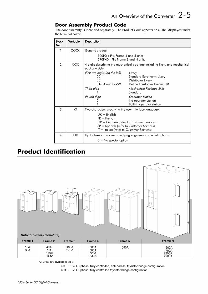
Product Identification
15A
590+ : 4Q 3-phase, fully controlled, anti-parallel thyristor bridge configuration591+ : 2Q 3-phase, fully controlled thyristor bridge configuration
All units are available as a:
Output Currents (armature):
Frame 4
380A500A
Frame 5
1580A
830A725A
Frame 1 Frame 2 Frame H
1200A1700A
2700A2200A
40A 70A
165A110A
35A180A
Frame 3
270A
2-6 An Overview of the Converter
590+ Series DC Digital Converter
Component Identification
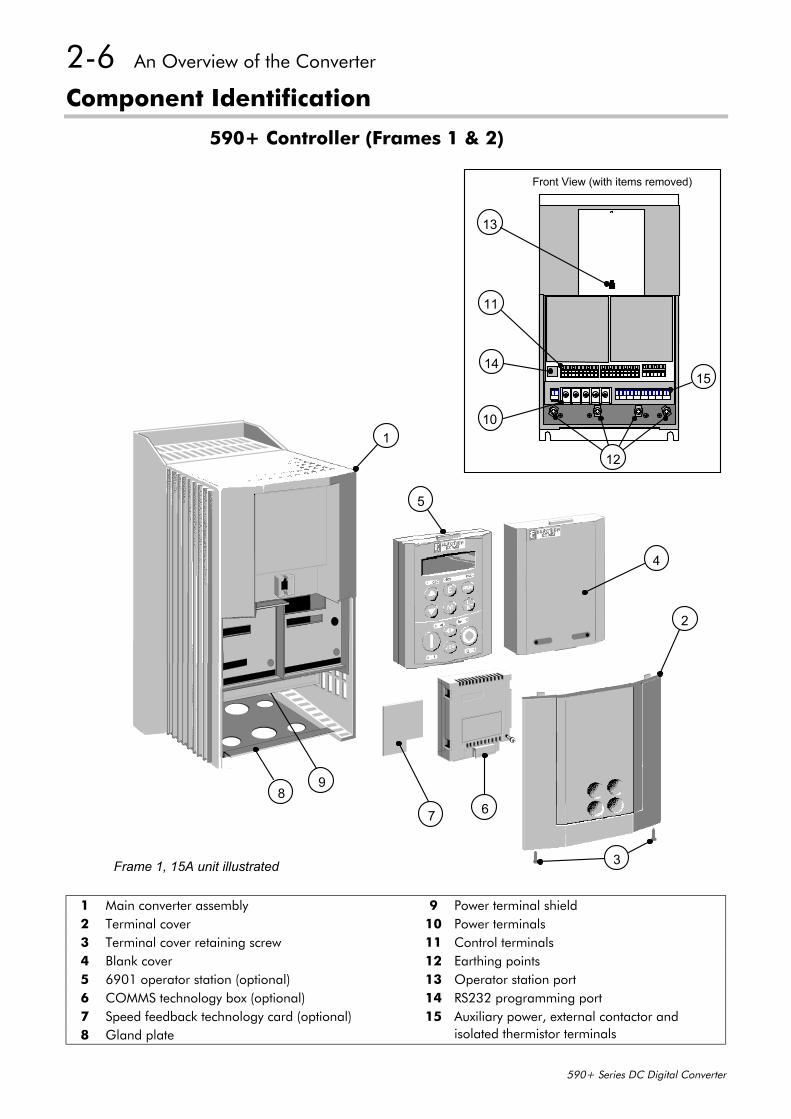
590+ Controller (Frames 1 & 2)
4
7
2
8
13
11
14
10
12
Front View (with items removed)
1
9
3
15
Frame 1, 15A unit illustrated
6
5
1 Main converter assembly 9 Power terminal shield2 Terminal cover 10 Power terminals3 Terminal cover retaining screw 11 Control terminals4 Blank cover 12 Earthing points5 6901 operator station (optional) 13 Operator station port6 COMMS technology box (optional) 14 RS232 programming port7 Speed feedback technology card (optional) 15 Auxiliary power, external contactor and8 Gland plate isolated thermistor terminals
An Overview of the Converter 2-7
590+ Series DC Digital Converter
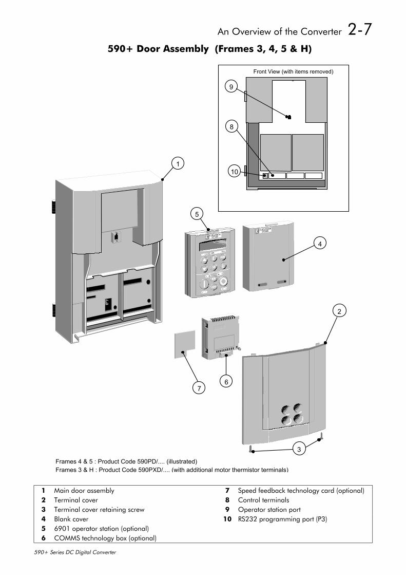
590+ Door Assembly (Frames 3, 4, 5 & H)
4
7
9
8
10
Front View (with items removed)
2
3
1
6
5
Frames 4 & 5 : Product Code 590PD/.... (illustrated)Frames 3 & H : Product Code 590PXD/.... (with additional motor thermistor terminals)
1 Main door assembly 7 Speed feedback technology card (optional)2 Terminal cover 8 Control terminals3 Terminal cover retaining screw 9 Operator station port4 Blank cover 10 RS232 programming port (P3)5 6901 operator station (optional)6 COMMS technology box (optional)
2-8 An Overview of the Converter
590+ Series DC Digital Converter
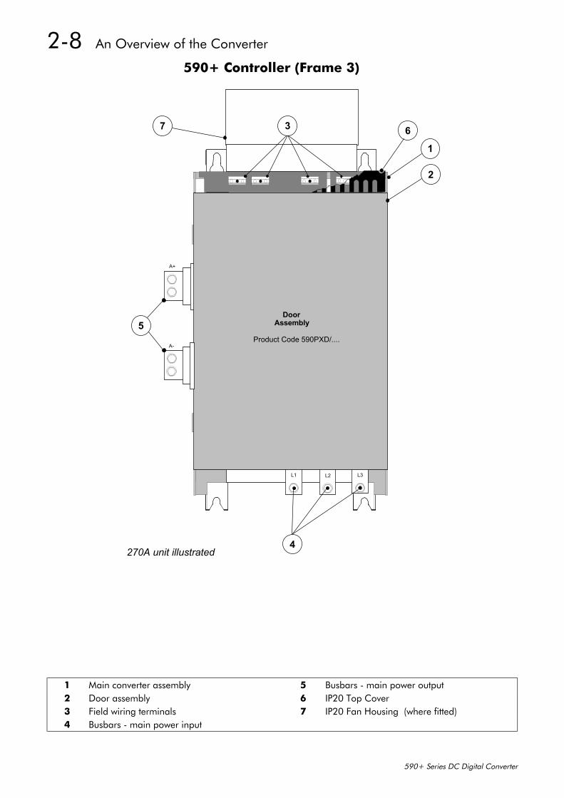
590+ Controller (Frame 3)
L1
4
L2 L3
1
2
7 63
A-
A+
5
270A unit illustrated
DoorAssembly
Product Code 590PXD/....
1 Main converter assembly 5 Busbars - main power output2 Door assembly 6 IP20 Top Cover3 Field wiring terminals 7 IP20 Fan Housing (where fitted)4 Busbars - main power input
An Overview of the Converter 2-9
590+ Series DC Digital Converter
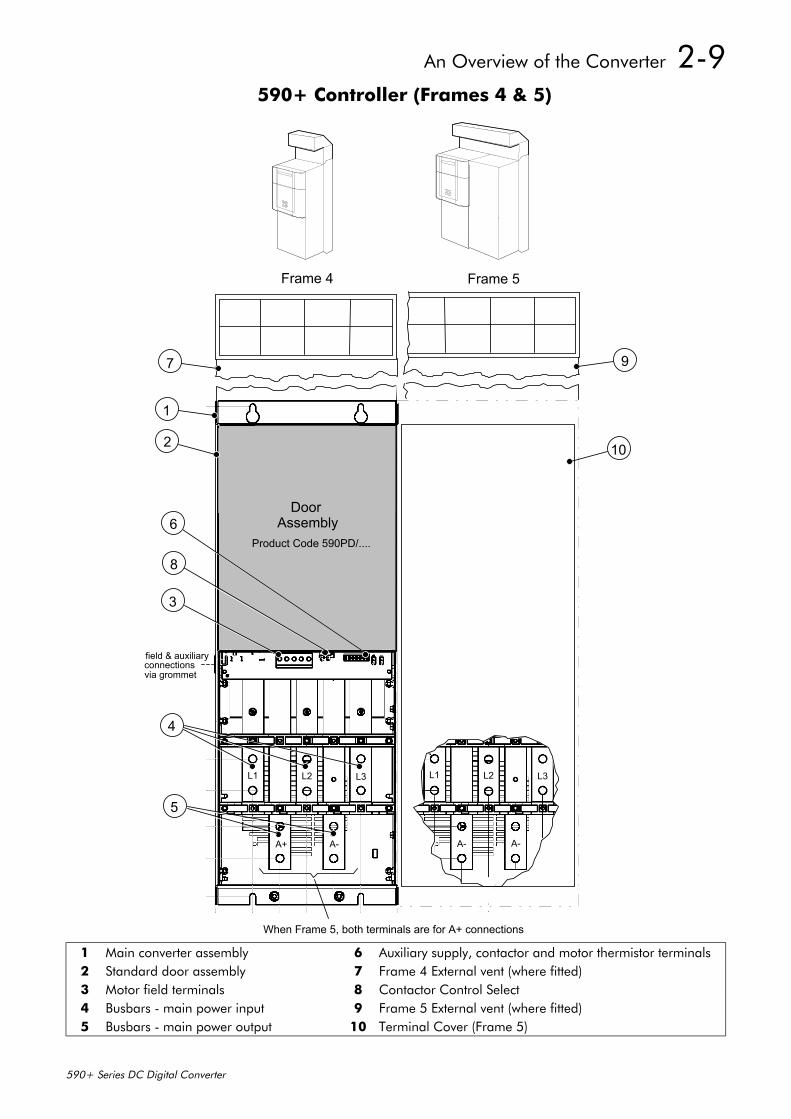
590+ Controller (Frames 4 & 5)
AssemblyDoor
1
2
L1 L2 L3
A+ A-
6
4
5
3
field & auxiliaryconnectionsvia grommet
Product Code 590PD/....
8
97
L1 L2 L3
A- A-
When Frame 5, both terminals are for A+ connections
10
Frame 4 Frame 5
1 Main converter assembly 6 Auxiliary supply, contactor and motor thermistor terminals2 Standard door assembly 7 Frame 4 External vent (where fitted)3 Motor field terminals 8 Contactor Control Select4 Busbars - main power input 9 Frame 5 External vent (where fitted)5 Busbars - main power output 10 Terminal Cover (Frame 5)
2-10 An Overview of the Converter
590+ Series DC Digital Converter
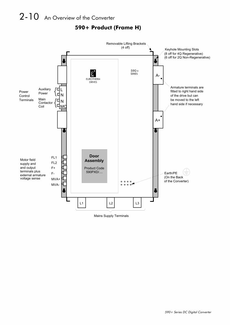
590+ Product (Frame H)
LNNMC
AuxiliaryPower
Contactor
FL1FL2F+
F-
MVA+
MVA-
Armature terminals arefitted to right hand sideof the drive but canbe moved to the lefthand side if necessary
L1 L2 L3
Mains Supply Terminals
A-
A+
PowerControlTerminals
supply and and outputterminals plusexternal armaturevoltage sense
Keyhole Mounting Slots(8 off for 4Q Regenerative)
Earth/PE(On the Backof the Converter)
EUROTHERMDRIVES
590+SERIES
Removable Lifting Brackets(4 off)
(6 off for 2Q Non-Regenerative)
Main
Coil
Motor fieldDoor
Assembly
Product Code590PXD/....

Installing the Converter 3-1
590+ Series DC Digital Converter
3 INSTALLING THE CONVERTERIMPORTANT: Read Chapter 12: “Certification for the Converter” before installing this unit.
Refer to “Installation Drawings”, page 3-31 for further information.
Mechanical Installation
Unpacking the Converter
Caution The packaging is combustible and, if disposed of in this manner incorrectly, may lead to
the generation of lethal toxic fumes.
Save the packaging in case of return. Improper packaging can result in transit damage.
Frame H PackagingThe larger converters (Frame H) are supplied in special packaging to protect the drive whilst intransit. Remove all fixings from the drive, see Figure 3-1. (The packaging is designed so that thesides can be removed to reveal the drive).
591+ 2Q Non-Regenerative Mounting Positions 590+ 4Q Regenerative Mounting Positions
Base Plate
Fixings to be removed
Fixings to be removed
Fixings to be removed
Lifting
(4 off)brackets
Fixings to be removed
Fixings to be removed
Fixings to be removed
Fixings to be removed
Lifting
(4 off)brackets
Base Plate
Figure 3-1 Lifting Details (Frame H)
Lifting the ConverterUse a safe and suitable lifting procedure when moving the drive. Never lift the drive by itsterminal connections. Refer to Chapter 11: Technical Specifications - Mechanical Details forweights.
Prepare a clear, flat surface to receive the drive before attempting to move it. Do not damage anyterminal connections when putting the drive down.
3-2 Installing the Converter
590+ Series DC Digital Converter
The larger converters (H) require the following:
• The drive is supplied with a lifting bracket fitted to each corner for hoisting. Remove thebrackets when the drive is in its final position, however, the fixings MUST be re-fitted.Refer to Chapter 11: “Technical Specifications” - Fixing Types and Torques.
• A plate is fitted to the base to enable the drive to be set-on-end by a forklift. Remove theplate before wiring the power terminals.
Frames 4 & 5 converters also have lifting eyes and a plate fitted to the base to enable the drive tobe set-on-end by a forklift. Remove the plate before wiring the power terminals.
Changing DC Output Terminals (Frame H)• Remove the left-hand cover plate(s) and retain the cover and screws.
• Remove and retain the 12 M6 nuts clamping the outgoing terminals to the cross plates.
• Remove the 12 M6 bolts securing the outgoing busbar assembly (assemblies). Remove theassembly (assemblies).
• Carefully remove the gasket(s) for use on the left-hand side.
• Refit the cover to the right-hand side of the drive.
• Refit the gasket to the left-hand side of the drive.
• Refit the terminal assemblies.Note: The 2Q terminal assembly is not polarised and may be fitted in any orientation. The 4Q
terminal assemblies are handed and must be reversed to fit on the left-hand side.
• Move the terminal markers as appropriate, the A+ terminal will still be at the bottom or ACinput at the end of the product.
• Tighten terminal assembly bolts to the torque given in Chapter 11.
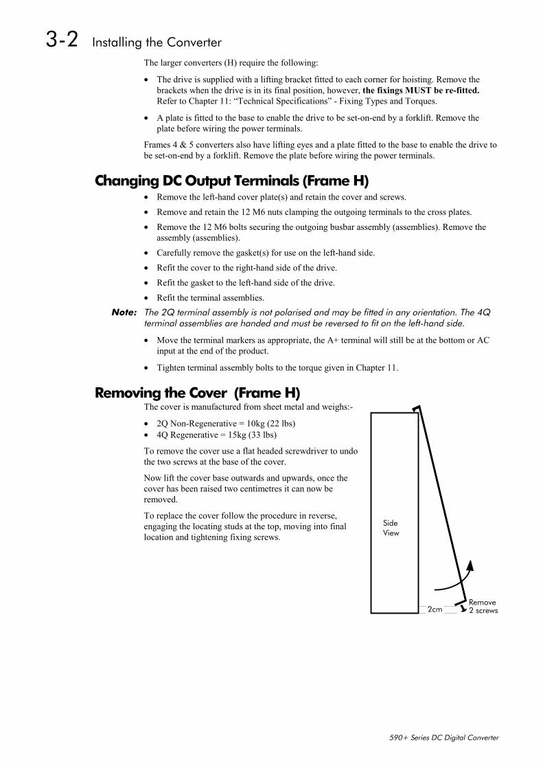
Removing the Cover (Frame H)The cover is manufactured from sheet metal and weighs:-
• 2Q Non-Regenerative = 10kg (22 lbs)• 4Q Regenerative = 15kg (33 lbs)
To remove the cover use a flat headed screwdriver to undothe two screws at the base of the cover.
Now lift the cover base outwards and upwards, once thecover has been raised two centimetres it can now beremoved.
To replace the cover follow the procedure in reverse,engaging the locating studs at the top, moving into finallocation and tightening fixing screws.
SideView
2cmRemove2 screws
Installing the Converter 3-3
590+ Series DC Digital Converter
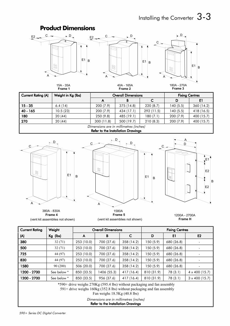
Product Dimensions
40A - 165A
D
BE1
A
CE2
15A - 35A
D
BE1
A
CE2
Frame 1 Frame 2180A - 270A
A
C
D
BE1
Frame 3
Current Rating (A)Current Rating (A)Current Rating (A)Current Rating (A) Weight in Kg (lbs)Weight in Kg (lbs)Weight in Kg (lbs)Weight in Kg (lbs) Overall DimensionsOverall DimensionsOverall DimensionsOverall Dimensions Fixing CentresFixing CentresFixing CentresFixing CentresAAAA BBBB CCCC DDDD E1E1E1E1
15 - 3515 - 3515 - 3515 - 35 6.4 (14) 200 (7.9) 375 (14.8) 220 (8.7) 140 (5.5) 360 (14.2)40 - 16540 - 16540 - 16540 - 165 10.5 (23) 200 (7.9) 434 (17.1) 292 (11.5) 140 (5.5) 418 (16.5)180180180180 20 (44) 250 (9.8) 485 (19.1) 180 (7.1) 200 (7.9) 400 (15.7)270270270270 20 (44) 300 (11.8) 500 (19.7) 210 (8.3) 200 (7.9) 400 (15.7)
Dimensions are in millimetres (inches)Refer to the Installation DrawingsRefer to the Installation DrawingsRefer to the Installation DrawingsRefer to the Installation Drawings
380A - 830A
(vent kit assemblies not shown)
C
BE1
A
D
Frame 4 1200A - 2700AFrame H
A
B
CD
E2
E2
E1
B
DD
E1
C
A
1580A
(vent kit assemblies not shown) Frame 5
Current RatingCurrent RatingCurrent RatingCurrent Rating WeightWeightWeightWeight Overall DimensionsOverall DimensionsOverall DimensionsOverall Dimensions Fixing CentresFixing CentresFixing CentresFixing Centres
(A)(A)(A)(A) Kg (lbs)Kg (lbs)Kg (lbs)Kg (lbs) AAAA BBBB CCCC DDDD E1E1E1E1 E2E2E2E2
380380380380 32 (71) 253 (10.0) 700 (27.6) 358 (14.2) 150 (5.9) 680 (26.8) -
500500500500 32 (71) 253 (10.0) 700 (27.6) 358 (14.2) 150 (5.9) 680 (26.8) -
725725725725 44 (97) 253 (10.0) 700 (27.6) 358 (14.2) 150 (5.9) 680 (26.8) -
830830830830 44 (97) 253 (10.0) 700 (27.6) 358 (14.2) 150 (5.9) 680 (26.8) -
1580158015801580 90 (200) 506 (20.0) 700 (27.6) 358 (14.2) 150 (5.9) 680 (26.8) -
1200 - 27001200 - 27001200 - 27001200 - 2700 See below * 850 (33.5) 1406 (55.3) 417 (16.4) 810 (31.9) 78 (3.1) 4 x 400 (15.7)
1200 - 27001200 - 27001200 - 27001200 - 2700 See below * 850 (33.5) 956 (37.6) 417 (16.4) 810 (31.9) 78 (3.1) 3 x 400 (15.7)
*590+ drive weighs 270Kg (595.4 lbs) without packaging and fan assembly 591+ drive weighs 160kg (352.8 lbs) without packaging and fan assembly
Fan weighs 18.5Kg (40.8 lbs)Dimensions are in millimetres (inches)
Refer to the Installation DrawingsRefer to the Installation DrawingsRefer to the Installation DrawingsRefer to the Installation Drawings
3-4 Installing the Converter
590+ Series DC Digital Converter
Mounting the Converter General installation details are given below for mounting the Converter, however, if you areinstalling the unit with an EMC filter refer to “External AC Supply EMC Filter Installation”,page 3-25.
Mount the unit vertically on a solid, flat, vertical surface. It is mounted using bolts or screws intofour fixing points (keyhole slots). The design allows the use of 100mm grid fixing.
It must be mounted inside a suitable cubicle. To comply with the European safety standards VDE0160 (1994)/EN50178 (1998), the cubicle must require a tool for opening.
Note: Holes for the mounting bolts or screws must be placed accurately.
Cover any units all ready mounted to the panel while drilling mounting holes to protect themfrom stray metal filings.
General Mounting HintsInsert the mounting studs from the rear of the panel. Attach lock washers and nuts part way on tothe lower mounting studs; these will help to keep the drive in place when mounting.
Caution Use proper lifting techniques when lifting and moving.
Lift the drive and engage the bottom slots safely on to the studs between the panel and lockwashers/nuts you have just fitted. Engage the top slots with the remaining mounting studs andfinger tighten the drive to the panel with lock washers and nuts. Finally, use the socket wrench totighten all nuts securely.
Check the drive and its housing for packing material, mounting debris, or any other material thatcould damage and/or restrict the operation of the equipment.
Recommended Tools
Socket wrench With a 6 Inch extension
Deep sockets M10, M13, M17, 7/16”, 1/2”
Screwdrivers Phillips No.2, flat blade - 0.5 x 3.0mm, 0.8 x 4.0mm
Wire cutters Small
Ventilation and Cooling RequirementsRefer to Chapter 11: “Technical Specifications” - Cooling.
The Converter gives off heat in normal operation and must therefore be mounted to allow thefree flow of air through the air entries and exits. Maintain the minimum air clearances given onthe drawings to ensure that heat generated by other adjacent equipment is not transmitted to theConverter, be aware that other equipment may have its own clearance requirements. Whenmounting two or more 590+’s together, these clearances are cumulative.
Ensure that the mounting surface is normally cool.
AC Line ChokeWe recommend that you always use the specified ac line choke with the Converterto provide a known supply impedance for effective operation of the thyristor transientsuppression circuits. At least 1% line impedance should be provided in the supply side of theconverter.
Refer to Chapter 11: “Technical Specifications” - AC Line Choke for selection details.

Installing the Converter 3-5
590+ Series DC Digital Converter
Installing the Fan (Frame H)Refer to Chapter 11: “Technical Specifications” - Cooling for fan ratings
The fan unit supplied should be installed on the cubicle, with or without ducting (refer to theInstallation Drawing). The drive is force-cooled using the fan units supplied with the drive. As ageneral rule allow at least 150mm (6 inches) of clear space above and below the drive for free airflow. We suggest the cubicle has an air inlet at the base of the cubicle equivalent to 4ft², variabledepending upon the filter type used, to allow the maximum throughput of air.
The fan assembly provided is permanently wiredas shown below.
Figure 3-2 Fan Wiring Diagram
Installing the External Vent Kit (Frames 4 & 5)Refer also to Figure 3-14 page 3-35 and Figure 3-16 page 3-37.
115V ac1234
PE/GRD
L
N
115V ac + 10%50/60Hz
230V ac1234
PE/GRD
L
N
230V ac + 10%50/60Hz
LNLN
LNLN
4.5A
2.25ACaution
3-6 Installing the Converter
590+ Series DC Digital Converter
Electrical InstallationIMPORTANT: Please read the Safety Information on page Cont. 3 & 4 before proceeding.
WARNING! Ensure that all wiring is electrically isolated and cannot be made “live”
unintentionally by other personnel.
Note: Refer to Chapter 11: “Technical Specifications” for additional Cabling Requirements andTerminal Block Wire Sizes.
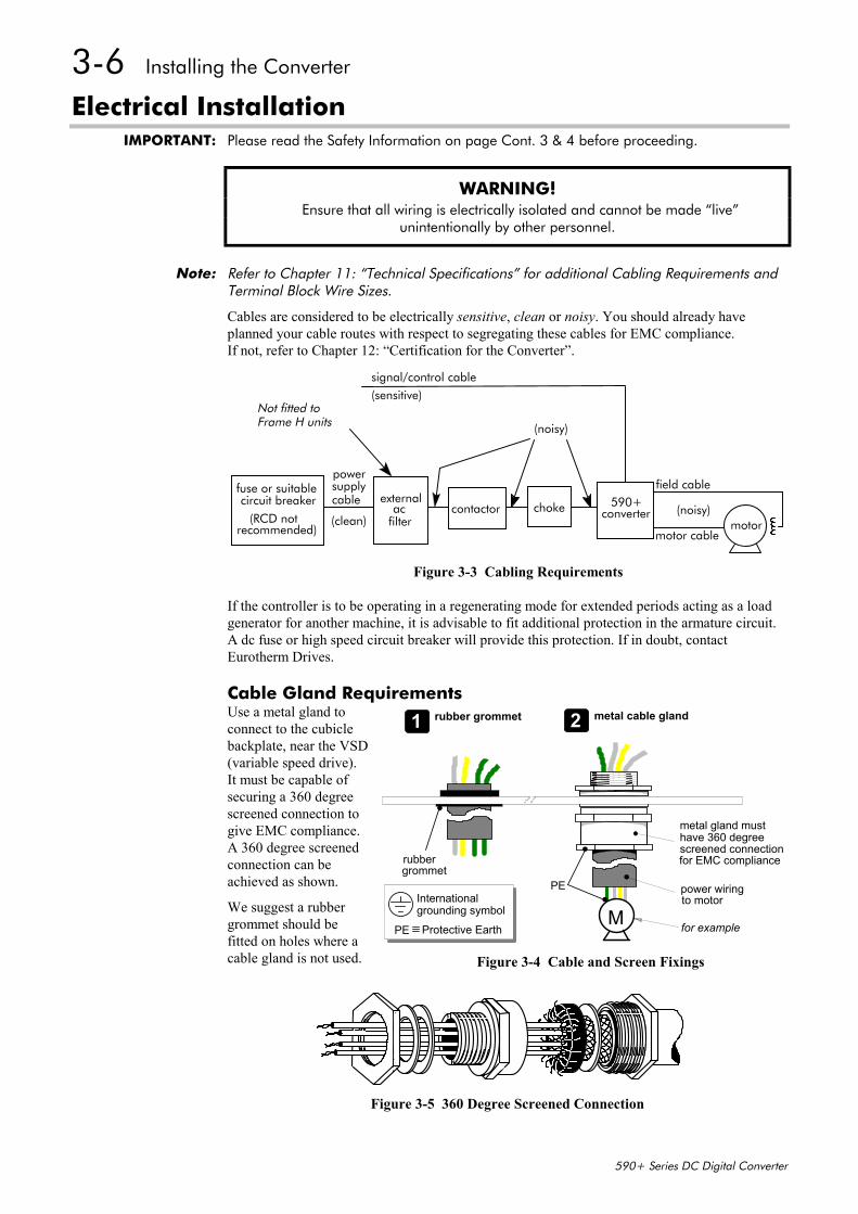
Cables are considered to be electrically sensitive, clean or noisy. You should already haveplanned your cable routes with respect to segregating these cables for EMC compliance.If not, refer to Chapter 12: “Certification for the Converter”.
If the controller is to be operating in a regenerating mode for extended periods acting as a loadgenerator for another machine, it is advisable to fit additional protection in the armature circuit.A dc fuse or high speed circuit breaker will provide this protection. If in doubt, contactEurotherm Drives.
Cable Gland RequirementsUse a metal gland toconnect to the cubiclebackplate, near the VSD(variable speed drive).It must be capable ofsecuring a 360 degreescreened connection togive EMC compliance.A 360 degree screenedconnection can beachieved as shown.
We suggest a rubbergrommet should befitted on holes where acable gland is not used.
Figure 3-5 360 Degree Screened Connection
590+converter
external
filter motor
powersupply
(clean)
(noisy)
(noisy)
signal/control cable(sensitive)
motor cable
fuse or suitablecable
accircuit breaker
(RCD notrecommended)
chokecontactor
field cable
Not fitted toFrame H units
Figure 3-3 Cabling Requirements
PE power wiringto motor
rubbergrommet
metal gland musthave 360 degreescreened connectionfor EMC compliance
MPE Protective Earth
Internationalgrounding symbol
1 rubber grommet 2 metal cable gland
for example
Figure 3-4 Cable and Screen Fixings

Installing the Converter 3-7
590+ Series DC Digital Converter
Figure 3-6 Minimum Connection Requirements (`general purpose’ configuration)
3-8 Installing the Converter
590+ Series DC Digital Converter
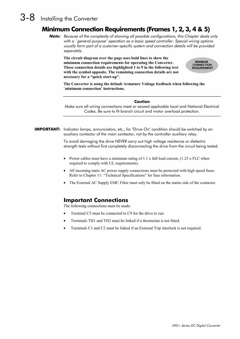
Minimum Connection Requirements (Frames 1, 2, 3, 4 & 5)Note: Because of the complexity of showing all possible configurations, this Chapter deals only
with a `general purpose’ operation as a basic speed controller. Special wiring optionsusually form part of a customer-specific system and connection details will be providedseparately.
The circuit diagram over the page uses bold lines to show theminimum connection requirements for operating the Converter.These connection details are highlighted 1 to 9 in the following textwith the symbol opposite. The remaining connection details are notnecessary for a “quick start-up”.
The Converter is using the default Armature Voltage feedback when following the`minimum connection’ instructions.
Caution Make sure all wiring connections meet or exceed applicable local and National Electrical
Codes. Be sure to fit branch circuit and motor overload protection.
IMPORTANT: Indicator lamps, annunciators, etc., for "Drive On" condition should be switched by anauxiliary contactor of the main contactor, not by the controller auxiliary relay.
To avoid damaging the drive NEVER carry out high voltage resistance or dielectricstrength tests without first completely disconnecting the drive from the circuit being tested.
• Power cables must have a minimum rating of 1.1 x full load current. (1.25 x FLC whenrequired to comply with UL requirements).
• All incoming main AC power supply connections must be protected with high speed fuses.Refer to Chapter 11: “Technical Specifications” for fuse information.
• The External AC Supply EMC Filter must only be fitted on the mains side of the contactor.
Important ConnectionsThe following connections must be made:
• Terminal C5 must be connected to C9 for the drive to run.
• Terminals TH1 and TH2 must be linked if a thermostat is not fitted.
• Terminals C1 and C2 must be linked if an External Trip interlock is not required.
MINIMUMCONNECTIONREQUIREMENT

Installing the Converter 3-9
590+ Series DC Digital Converter
Protective Earth Connections (PE) - (Frames 1, 2, 3, 4 & 5)
A+
4 3 L1 L2
F- F+ PE A-
L3 PE
FIELD OUTPUT
+
ARMATURE
MPE
*
PROTECTIVEEARTH
Filter
StartContactorCON
3-PHASE SUPPLY110V - 690VAC
High SpeedFuses
star-point earthnear drive
AC Line Choke
+
3-PHASE
CONTACTOR
3 PH 50/60Hz
DCMOTOR
* use internalfield connection
for EMC compliance
(optional)
EXTERNAL
(D6) (D5)
(D4) (D3)
IMPORTANT: The drive and filter (if fitted) must be permanently earthedpermanently earthedpermanently earthedpermanently earthed. Each conductor used forpermanent earthing must individually meet the requirements for a protective earthconductor.
For installations to EN 60204 in Europe:
• For permanent earthing, the converter requires either two individual incoming protectiveearth conductors (<10mm² cross-section), or one conductor (≥10mm² cross-section)connected to an independent protective earth/ground point near the drive.
• Run the motor protective earth/ground connection in parallel with the motor supplyconductors, ideally in the same conduit/screen/armour, and connect to an independentprotective earth/ground point near the drive.
• Connect the drive to the independent earth/ground point.
Refer to Chapter 12: “Certification for the Converter” - Screening & Earthing (cubiclemounted, Class B).
Protect the incoming mains supply, detailed in Chapter 11: “Technical Specifications” - PowerDetails, using a suitable fuse or circuit breaker (a circuit breaker, e.g. RCD, ELCB, GFCI, is notrecommended, refer to “Earth Fault Monitoring Systems”, page 3-30.)
1MINIMUMCONNECTIONREQUIREMENT
3-10 Installing the Converter
590+ Series DC Digital Converter
Power Wiring Connections (Frames 1, 2, 3, 4 & 5)
WARNING! Power terminals carry electrical voltage which can be lethal. Never work on any
control equipment or motors without first removing all power supplies from theequipment.
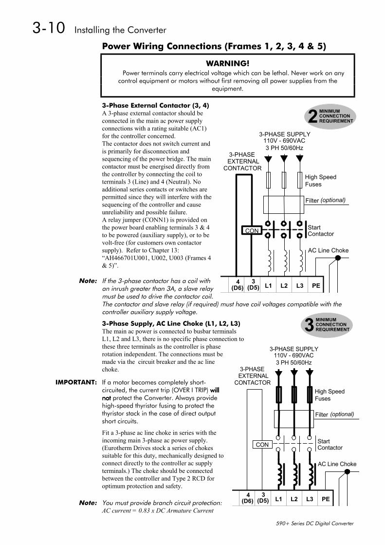
3-Phase External Contactor (3, 4)A 3-phase external contactor should beconnected in the main ac power supplyconnections with a rating suitable (AC1)for the controller concerned.The contactor does not switch current andis primarily for disconnection andsequencing of the power bridge. The maincontactor must be energised directly fromthe controller by connecting the coil toterminals 3 (Line) and 4 (Neutral). Noadditional series contacts or switches arepermitted since they will interfere with thesequencing of the controller and causeunreliability and possible failure.A relay jumper (CONN1) is provided onthe power board enabling terminals 3 & 4to be powered (auxiliary supply), or to bevolt-free (for customers own contactorsupply). Refer to Chapter 13:“AH466701U001, U002, U003 (Frames 4& 5)”.
Note: If the 3-phase contactor has a coil withan inrush greater than 3A, a slave relaymust be used to drive the contactor coil.The contactor and slave relay (if required) must have coil voltages compatible with thecontroller auxiliary supply voltage.
3-Phase Supply, AC Line Choke (L1, L2, L3)The main ac power is connected to busbar terminalsL1, L2 and L3, there is no specific phase connection tothese three terminals as the controller is phaserotation independent. The connections must bemade via the circuit breaker and the ac linechoke.
IMPORTANT: If a motor becomes completely short-circuited, the current trip (OVER I TRIP) will will will willnotnotnotnot protect the Converter. Always providehigh-speed thyristor fusing to protect thethyristor stack in the case of direct outputshort circuits.
Fit a 3-phase ac line choke in series with theincoming main 3-phase ac power supply.(Eurotherm Drives stock a series of chokessuitable for this duty, mechanically designed toconnect directly to the controller ac supplyterminals.) The choke should be connectedbetween the controller and Type 2 RCD foroptimum protection and safety.
Note: You must provide branch circuit protection:AC current = 0.83 x DC Armature Current
4 3L1 L2 L3 PE
Filter
StartContactorCON
3-PHASE SUPPLY110V - 690VAC
High SpeedFuses
AC Line Choke
3-PHASE
CONTACTOR
3 PH 50/60Hz
(optional)
EXTERNAL
(D6) (D5)
2MINIMUMCONNECTIONREQUIREMENT
3MINIMUMCONNECTIONREQUIREMENT
4 3L1 L2 L3 PE
Filter
StartContactorCON
3-PHASE SUPPLY110V - 690VAC
High SpeedFuses
AC Line Choke
3-PHASE
CONTACTOR
3 PH 50/60Hz
(optional)
EXTERNAL
(D6) (D5)
Installing the Converter 3-11
590+ Series DC Digital Converter
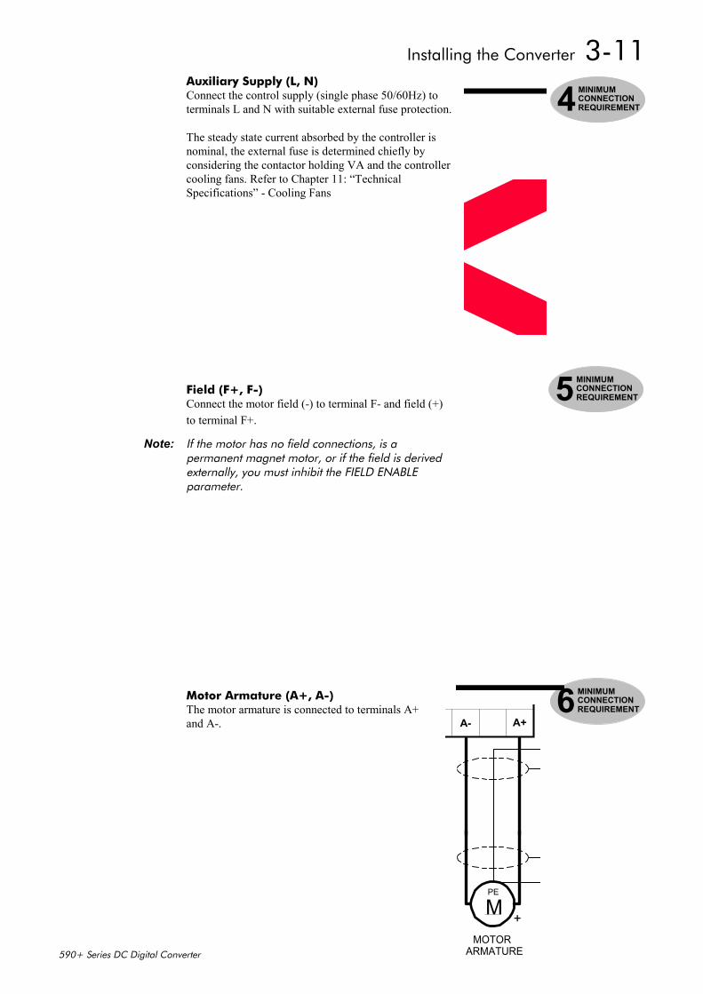
Auxiliary Supply (L, N)Connect the control supply (single phase 50/60Hz) toterminals L and N with suitable external fuse protection.
The steady state current absorbed by the controller isnominal, the external fuse is determined chiefly byconsidering the contactor holding VA and the controllercooling fans. Refer to Chapter 11: “TechnicalSpecifications” - Cooling Fans
Field (F+, F-)Connect the motor field (-) to terminal F- and field (+)to terminal F+.
Note: If the motor has no field connections, is apermanent magnet motor, or if the field is derivedexternally, you must inhibit the FIELD ENABLEparameter.
Motor Armature (A+, A-)The motor armature is connected to terminals A+and A-.
4MINIMUMCONNECTIONREQUIREMENT
5MINIMUMCONNECTIONREQUIREMENT
6MINIMUMCONNECTIONREQUIREMENT
A+A-
ARMATURE
MPE
+MOTOR
3-12 Installing the Converter
590+ Series DC Digital Converter
External AC Field (FL1, FL2)(Not available on Frame 1 units)
If an external field supply is required to the controller forapplication reasons, connect this supply to terminals FL1and FL2. The magnitude of this voltage is determined by thedesired field voltage. The supply must be protectedexternally with suitable fuses. Always derive the supply fromthe Red and Yellow phases of the main power supply, withthe Red phase connected to terminal FL1 and the Yellowphase to terminal FL2.
Note: You must provide branch circuit and overloadprotection. Use internal field connection for EMCcompliance.
IMPORTANT: It is important that connection of the controller and the external field supply is consistentwhen using an externally supplied field regulator. The supply must be derived from L1(Red) and L2 (Yellow) phases directly or indirectly through a single-phase transformer. L1must be connected to FL1, and L2 connected to FL2.
To change the controller from an internal to an external field type refer to Motor FieldConnections.
Thermistor (TH1, TH2) Terminals TH1 and TH2 must be linked if sensors are not fitted.The motor temperature alarm (THERMOSTAT) cannot be inhibitedin software.
We recommend that you protect the dc motor against overtemperature by theuse of temperature sensitive resistors or switches in the field and interpolewindings of the machine.
When the motor is fitted with over-temperature sensing devices, such asthermostats or PTC thermistors, these should be connected (in series)between terminals TH1 and TH2.
• Thermistors must have a combined working resistance of 750Ω or less,rising to 4kΩ at over-temperature. These thermistors are classified byIEC34-II as Mark A.
• Temperature switches must be normally closed, and open at ratedtemperature.
The controller’s thermistor alarm will activate at 3kΩ.
The over temperature alarm is latched in software and must be reset by re-starting the Converter.
7MINIMUMCONNECTIONREQUIREMENT
TH2TH1
THERMISTOR
#
MOTOR
THERM-THERM+
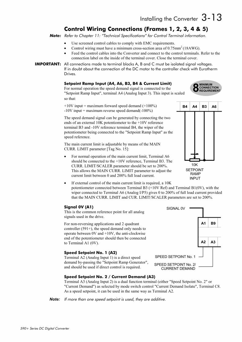
Installing the Converter 3-13
590+ Series DC Digital Converter
Control Wiring Connections (Frames 1, 2, 3, 4 & 5)Note: Refer to Chapter 11: “Technical Specifications” for Control Terminal information.
• Use screened control cables to comply with EMC requirements.• Control wiring must have a minimum cross-section area of 0.75mm2 (18AWG).• Feed the control cables into the Converter and connect to the control terminals. Refer to the
connection label on the inside of the terminal cover. Close the terminal cover.IMPORTANT: All connections made to terminal blocks A, B and C must be isolated signal voltages.
If in doubt about the connection of the DC motor to the controller check with EurothermDrives.
Setpoint Ramp Input (A4, A6, B3, B4 & Current Limit) For normal operation the speed demand signal is connected to the"Setpoint Ramp Input", terminal A4 (Analog Input 3). This input is scaledso that:
+10V input = maximum forward speed demand (+100%) -10V input = maximum reverse speed demand(-100%)
The speed demand signal can be generated by connecting the twoends of an external 10K potentiometer to the +10V referenceterminal B3 and -10V reference terminal B4, the wiper of thepotentiometer being connected to the "Setpoint Ramp Input" as thespeed reference.
The main current limit is adjustable by means of the MAINCURR. LIMIT parameter [Tag No. 15]:
• For normal operation of the main current limit, Terminal A6should be connected to the +10V reference, Terminal B3. TheCURR. LIMIT/SCALER parameter should be set to 200%.This allows the MAIN CURR. LIMIT parameter to adjust thecurrent limit between 0 and 200% full load current.
• If external control of the main current limit is required, a 10Kpotentiometer connected between Terminal B3 (+10V Ref) and Terminal B1(0V), with thewiper connected to Terminal A6 (Analog I/P5) gives 0 to 200% of full load current providedthat the MAIN CURR. LIMIT and CUR. LIMIT/SCALER parameters are set to 200%.
Signal 0V (A1)This is the common reference point for all analogsignals used in the drive.
For non-reversing applications and 2 quadrantcontroller (591+), the speed demand only needs tooperate between 0V and +10V, the anti-clockwiseend of the potentiometer should then be connectedto Terminal A1 (0V).
Speed Setpoint No. 1 (A2)Terminal A2 (Analog Input 1) is a direct speeddemand by-passing the "Setpoint Ramp Generator",and should be used if direct control is required.
Speed Setpoint No. 2 / Current Demand (A3)Terminal A3 (Analog Input 2) is a dual function terminal (either "Speed Setpoint No. 2" or"Current Demand") as selected by mode switch control "Current Demand Isolate", Terminal C8.As a speed setpoint, it can be used in the same way as Terminal A2.
Note: If more than one speed setpoint is used, they are additive.
8MINIMUMCONNECTIONREQUIREMENT
SETPOINTRAMP
10K
B3A4B4 A6
INPUT
SIGNAL 0V
SPEED SETPOINT No. 1
CURRENT DEMAND
B9A1
A3A2
SPEED SETPOINT No. 2/
3-14 Installing the Converter
590+ Series DC Digital Converter
Enable, Start/Run, Emergency Stop Relay (B8, B9, C3, C5, C9)
Terminal C5 (Enable) must be connected to Terminal C9 (+24V) inorder to allow the drive to run.
StartThe basic run/start sequence of thecontroller is provided by Terminal C3(Start/Run), although othersafeguards for extra protection areprovided by Terminal B8 (ProgramStop) and Terminal B9 (Coast Stop).
Assuming that the Program Stop andCoast Stop terminals are held TRUE,then a single contact connectedbetween Terminal C9 (+24V) andTerminal C3 (Start/Run) when closedwill cause the controller to energisethe Main Contactor and, providedTerminal C5 (Enable) is also TRUE,will run the associated DC motor.
When the single contact to TerminalC3 (Start/Run) is opened, thecontroller will decelerate the motor tozero speed at a rate determined by the STOP TIME parameter’s value and the MAIN CURR.LIMIT value. Refer to Chapter 6: “Application Programming” - STOP RATES for furtherinformation.
Note: The Enable input is useful to inhibit the drive without opening the main contactor,however, it is not a safe mode of operation as the drive dc output is only reduced to zero.If the equipment controlled by the drive is to be serviced, then this method should beavoided and the drive disabled and isolated.
A regenerative drive can be stopped using a Normal Stop, a Program Stop, or anEmergency Stop, as described below. However, a non-regenerative drive can only be madeto stop faster than friction and loading will allow by Dynamic Braking.
Normal StopIf the +24V is removed from Terminal C3 whilst the drive is controlling the motor under "Run"conditions, the controller will cause the motor to decelerate rapidly to rest at a rate determinedby STOP LIMIT, STOP TIME and CURR. LIMIT.
Program StopIf the +24V is removed from Terminal B8 whilst the drive is controlling the motor under "Run"conditions, the controller will cause the motor to decelerate rapidly to rest at a rate determinedby PROG STOP I LIM, PROG STOP LIMIT and PROG STOP TIME. If the signal is re-applied to Terminal B8, the motor remains stationary until a new Start command is applied toTerminal C3 (Start/Run).
Emergency StopAdditional terminals, Terminal B8 (Program Stop) and Terminal B9 (Coast Stop), provide extrafacilities for the control of the regenerative controller:
• Terminal B9 (Coast Stop) must be held at +24V to allow closure of the main contactor, theconnection provides the power supply to allow the electronics to operate the auxiliary relayand hence the main contactor.
Connect Terminal B9 (Coast Stop) to Terminal C9 (+24V) via a normally open delay-on-de-energisation contact of an "emergency" stop relay. The emergency stop relay should not bepart of the normal sequencing of the system, which is implemented via the Start contacts, but
9MINIMUMCONNECTIONREQUIREMENT
EMERGENCYSTOPRELAY
SIGNAL 0V
START/
ENABLE
B9A1 B8 C5 C3 C9
PROGRAMSTOPCOAST
STOPRUN
Installing the Converter 3-15
590+ Series DC Digital Converter
is a relay which can be operated in exceptional circumstances where human safety is ofparamount importance.
• Terminal B8 (Program Stop) provides a facility for regenerative braking on a 4 Quadrantdrive (590+).
Zero Speed, Drive Healthy, Drive Ready (B5, B6, B7)These digital output terminals provide a +24V dc output signal undercertain conditions. This allows for the connection of relays which, inconjunction with the Enable, Start/Run and Emergency Stop relay, canbe used to enhance the safe starting and stopping of the controller.
These are configurable outputs and can be used as required in thecontrol system design, i.e. cubicle door lamps, connection to a suitablePLC.
(The diagram shows a simple default configuration).
Analog Tachometer (G1, G2, G3, G4)Refer to Chapter 13: “Standard and Optional Equipment” - OptionalEquipment for further information.
An Analog Tachometer is connected to the Converter using a screenedtwisted pair cable throughout its entire length to provide speed feedbackvia the Tacho Calibration Option Board. This provides facility for anAC or DC tachometer. The screen is grounded or earthed only at thedrive end, any other grounding arrangement may cause problems.
Terminals G1 & G2 are for AC tacho connections.
Terminals G3 & G4 are for DC tacho connections.
Note: The speed loop is set-up for an analog tacho by the SPEED FBKSELECT parameter in the SPEED LOOP function block. SelectANALOG TACH for this parameter.
If an AC tachogenerator is used the output is rectified toproduce the dc feedback to the speed loop. Consequently, thecontroller can only be used with a positive setpoint.
Refer to Chapter 4: “Operating the Converter” for set-up information.
External Trip (C1, C2)Terminals C1 and C2 must be linked if an External Trip interlock is notrequired.
This input terminal provides an external trip facility to any normally-closedtrip switch , e.g. for vent fan overload protection.
ZEROSPEED
DRIVEHEALTHY
DRIVEREADY
B5 B6 B7
S
S
S
RL
RL
RL
ZS
C1 C2
EXTERNALTRIP
#
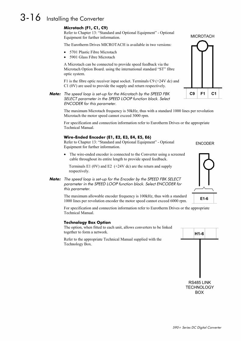
3-16 Installing the Converter
590+ Series DC Digital Converter
Microtach (F1, C1, C9)Refer to Chapter 13: “Standard and Optional Equipment” - OptionalEquipment for further information.
The Eurotherm Drives MICROTACH is available in two versions:
• 5701 Plastic Fibre Microtach• 5901 Glass Fibre Microtach
A Microtach can be connected to provide speed feedback via theMicrotach Option Board. using the international standard “ST” fibreoptic system.
F1 is the fibre optic receiver input socket. Terminals C9 (+24V dc) andC1 (0V) are used to provide the supply and return respectively.
Note: The speed loop is set-up for the Microtach by the SPEED FBKSELECT parameter in the SPEED LOOP function block. SelectENCODER for this parameter.
The maximum Microtach frequency is 50kHz, thus with a standard 1000 lines per revolutionMicrotach the motor speed cannot exceed 3000 rpm.
For specification and connection information refer to Eurotherm Drives or the appropriateTechnical Manual.
Wire-Ended Encoder (E1, E2, E3, E4, E5, E6)Refer to Chapter 13: “Standard and Optional Equipment” - OptionalEquipment for further information.
• The wire-ended encoder is connected to the Converter using a screenedcable throughout its entire length to provide speed feedback.
Terminals E1 (0V) and E2 (+24V dc) are the return and supplyrespectively.
Note: The speed loop is set-up for the Encoder by the SPEED FBK SELECTparameter in the SPEED LOOP function block. Select ENCODER forthis parameter.
The maximum allowable encoder frequency is 100kHz, thus with a standard1000 lines per revolution encoder the motor speed cannot exceed 6000 rpm.
For specification and connection information refer to Eurotherm Drives or the appropriateTechnical Manual.
Technology Box OptionThe option, when fitted to each unit, allows converters to be linkedtogether to form a network.
Refer to the appropriate Technical Manual supplied with theTechnology Box.
F1C9 C1
MICROTACH
ENCODER
E1-6
H1-6
RS485 LINKTECHNOLOGY
BOX
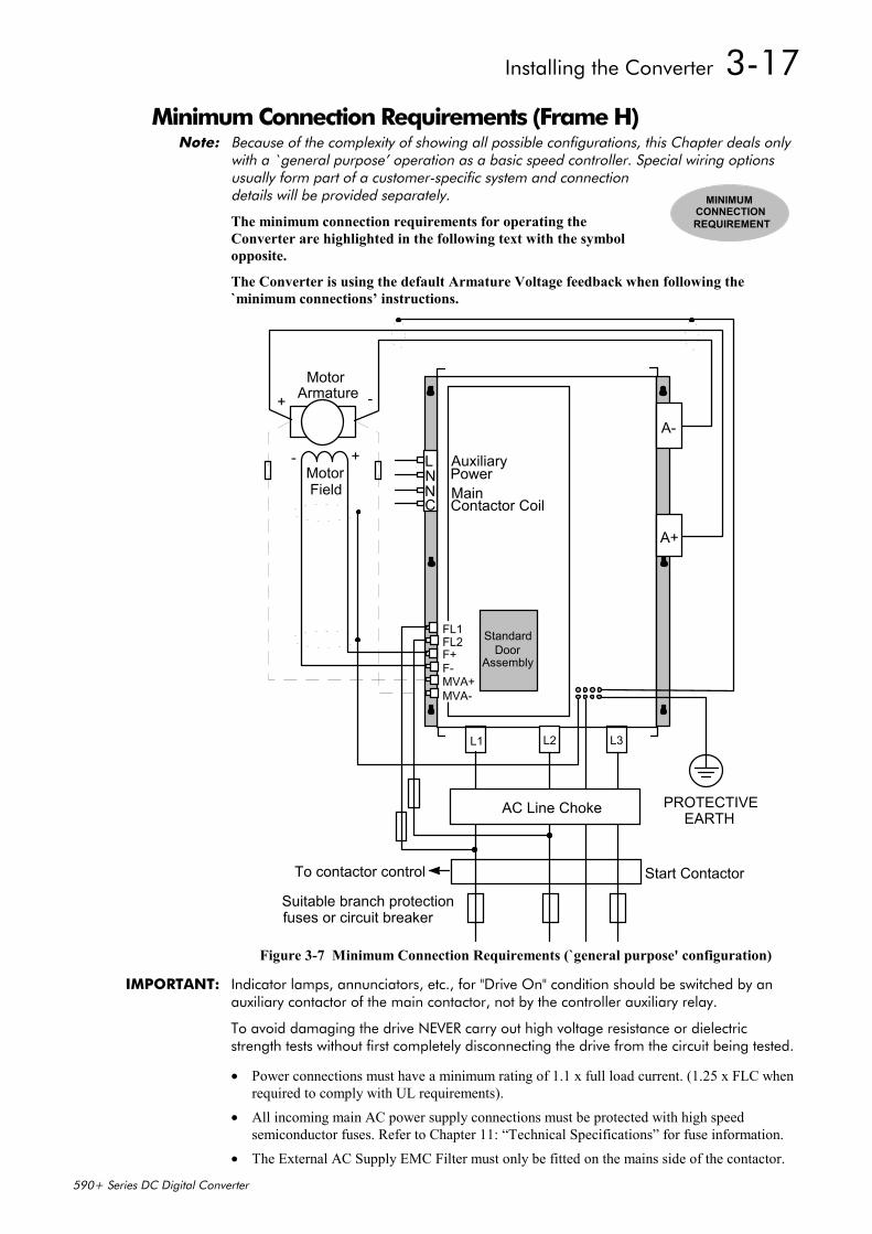
Installing the Converter 3-17
590+ Series DC Digital Converter
Minimum Connection Requirements (Frame H)Note: Because of the complexity of showing all possible configurations, this Chapter deals only
with a `general purpose’ operation as a basic speed controller. Special wiring optionsusually form part of a customer-specific system and connectiondetails will be provided separately.
The minimum connection requirements for operating theConverter are highlighted in the following text with the symbolopposite.
The Converter is using the default Armature Voltage feedback when following the`minimum connections’ instructions.
LNNC
L1 L2 L3
A-
A+
FL1FL2F+F-MVA+MVA-
AuxiliaryPowerMain
-Motor
Armature+
+-MotorField
Start Contactor
Suitable branch protectionfuses or circuit breaker
To contactor control
Contactor Coil
StandardDoor
Assembly
AC Line Choke PROTECTIVEEARTH
Figure 3-7 Minimum Connection Requirements (`general purpose' configuration)
IMPORTANT: Indicator lamps, annunciators, etc., for "Drive On" condition should be switched by anauxiliary contactor of the main contactor, not by the controller auxiliary relay.
To avoid damaging the drive NEVER carry out high voltage resistance or dielectricstrength tests without first completely disconnecting the drive from the circuit being tested.
• Power connections must have a minimum rating of 1.1 x full load current. (1.25 x FLC whenrequired to comply with UL requirements).
• All incoming main AC power supply connections must be protected with high speedsemiconductor fuses. Refer to Chapter 11: “Technical Specifications” for fuse information.
• The External AC Supply EMC Filter must only be fitted on the mains side of the contactor.
MINIMUMCONNECTIONREQUIREMENT
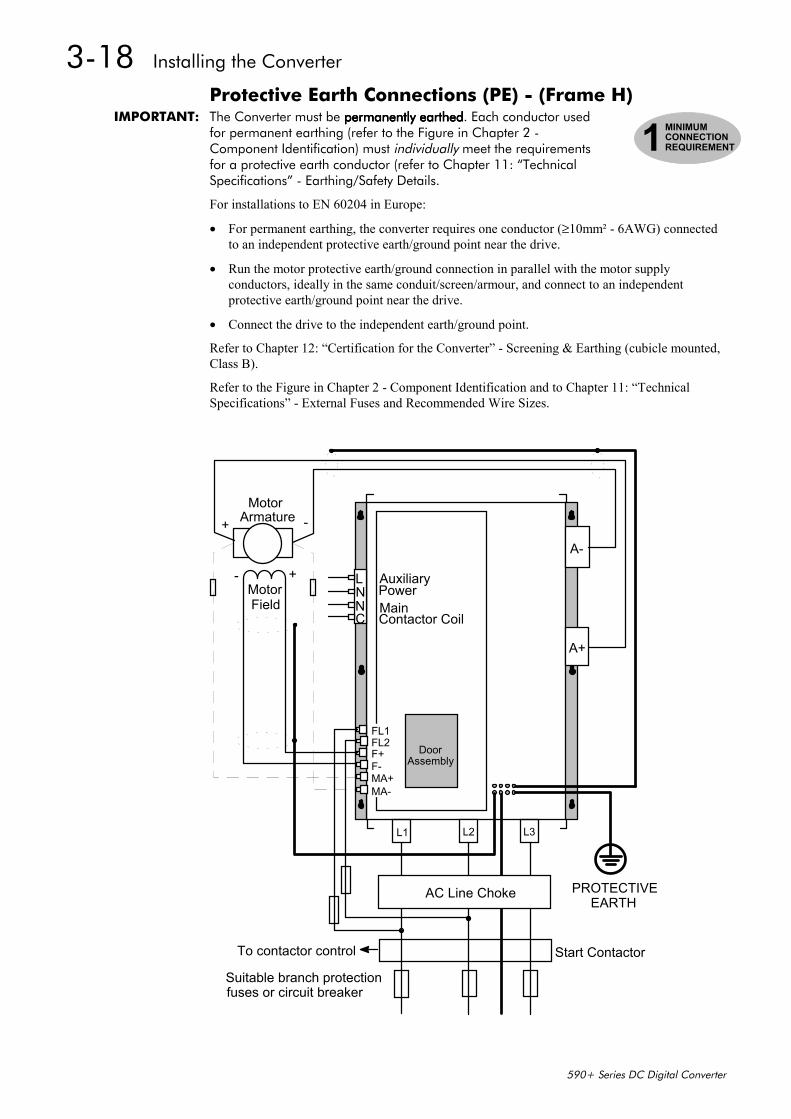
3-18 Installing the Converter
590+ Series DC Digital Converter
Protective Earth Connections (PE) - (Frame H)IMPORTANT: The Converter must be permanently earthedpermanently earthedpermanently earthedpermanently earthed. Each conductor used
for permanent earthing (refer to the Figure in Chapter 2 -Component Identification) must individually meet the requirementsfor a protective earth conductor (refer to Chapter 11: “TechnicalSpecifications” - Earthing/Safety Details.
For installations to EN 60204 in Europe:
• For permanent earthing, the converter requires one conductor (≥10mm² - 6AWG) connectedto an independent protective earth/ground point near the drive.
• Run the motor protective earth/ground connection in parallel with the motor supplyconductors, ideally in the same conduit/screen/armour, and connect to an independentprotective earth/ground point near the drive.
• Connect the drive to the independent earth/ground point.
Refer to Chapter 12: “Certification for the Converter” - Screening & Earthing (cubicle mounted,Class B).
Refer to the Figure in Chapter 2 - Component Identification and to Chapter 11: “TechnicalSpecifications” - External Fuses and Recommended Wire Sizes.
LNNC
L1 L2 L3
A-
A+
FL1FL2F+F-MA+MA-
AuxiliaryPowerMain
-Motor
Armature+
+-MotorField
Start Contactor
Suitable branch protectionfuses or circuit breaker
To contactor control
Contactor Coil
DoorAssembly
AC Line Choke PROTECTIVEEARTH
1MINIMUMCONNECTIONREQUIREMENT
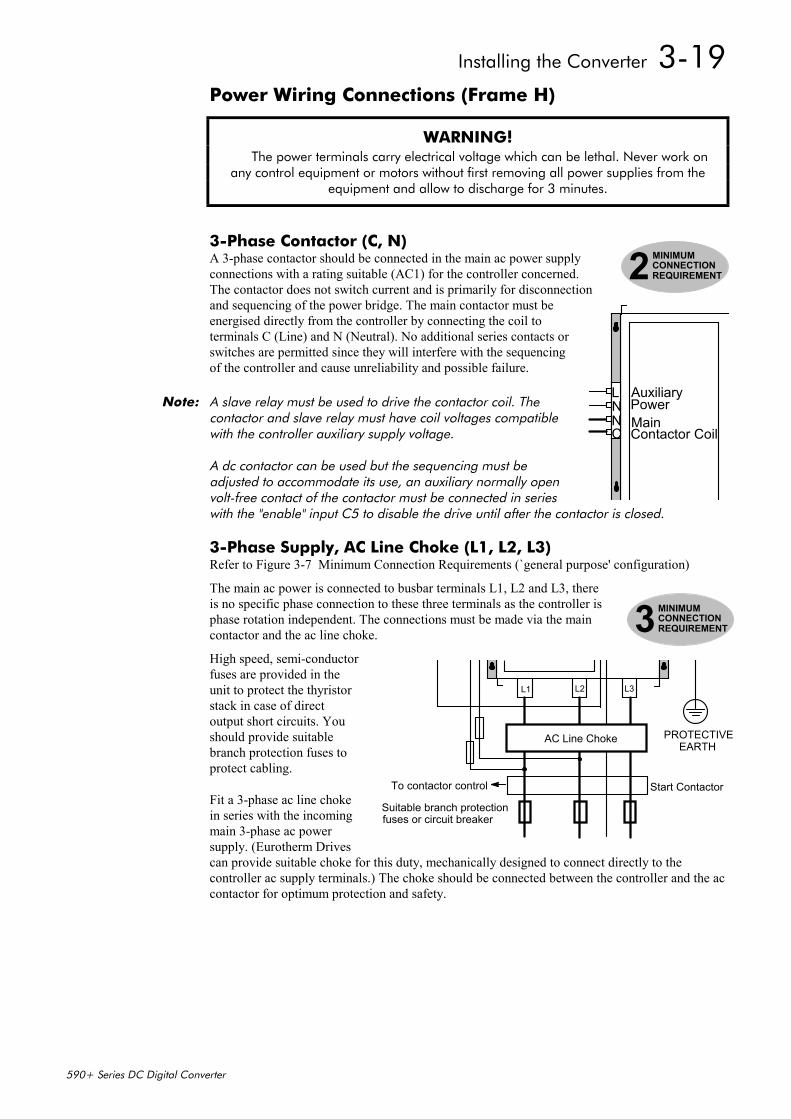
Installing the Converter 3-19
590+ Series DC Digital Converter
Power Wiring Connections (Frame H)
WARNING! The power terminals carry electrical voltage which can be lethal. Never work onany control equipment or motors without first removing all power supplies from the
equipment and allow to discharge for 3 minutes.
3-Phase Contactor (C, N) A 3-phase contactor should be connected in the main ac power supplyconnections with a rating suitable (AC1) for the controller concerned. The contactor does not switch current and is primarily for disconnectionand sequencing of the power bridge. The main contactor must beenergised directly from the controller by connecting the coil toterminals C (Line) and N (Neutral). No additional series contacts orswitches are permitted since they will interfere with the sequencingof the controller and cause unreliability and possible failure.
Note: A slave relay must be used to drive the contactor coil. Thecontactor and slave relay must have coil voltages compatiblewith the controller auxiliary supply voltage.
A dc contactor can be used but the sequencing must beadjusted to accommodate its use, an auxiliary normally openvolt-free contact of the contactor must be connected in serieswith the "enable" input C5 to disable the drive until after the contactor is closed.
3-Phase Supply, AC Line Choke (L1, L2, L3)Refer to Figure 3-7 Minimum Connection Requirements (`general purpose' configuration)
The main ac power is connected to busbar terminals L1, L2 and L3, thereis no specific phase connection to these three terminals as the controller isphase rotation independent. The connections must be made via the maincontactor and the ac line choke.
High speed, semi-conductorfuses are provided in theunit to protect the thyristorstack in case of directoutput short circuits. Youshould provide suitablebranch protection fuses toprotect cabling.
Fit a 3-phase ac line chokein series with the incomingmain 3-phase ac powersupply. (Eurotherm Drivescan provide suitable choke for this duty, mechanically designed to connect directly to thecontroller ac supply terminals.) The choke should be connected between the controller and the accontactor for optimum protection and safety.
2MINIMUMCONNECTIONREQUIREMENT
LNNC
AuxiliaryPowerMainContactor Coil
3MINIMUMCONNECTIONREQUIREMENT
L1 L2 L3
Start Contactor
Suitable branch protectionfuses or circuit breaker
To contactor control
AC Line Choke PROTECTIVEEARTH
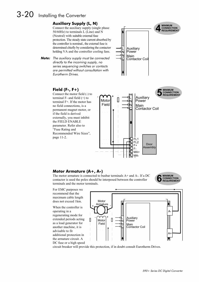
3-20 Installing the Converter
590+ Series DC Digital Converter
Auxiliary Supply (L, N)Connect the auxiliary supply (single phase50/60Hz) to terminals L (Line) and N(Neutral) with suitable external fuseprotection. The steady state current absorbed bythe controller is nominal., the external fuse isdetermined chiefly by considering the contactorholding VA and the controller cooling fans.
Note: The auxiliary supply must be connecteddirectly to the incoming supply, noseries sequencing switches or contactsare permitted without consultation withEurotherm Drives.
Field (F-, F+)Connect the motor field (-) toterminal F- and field (+) toterminal F+. If the motor hasno field connections, is apermanent magnet motor, orif the field is derivedexternally, you must inhibitthe FIELD ENABLEparameter. Refer also to“Fuse Rating andRecommended Wire Sizes”,page 11-2.
Motor Armature (A+, A-)The motor armature is connected to busbar terminals A+ and A-. If a DCcontactor is used the poles should be interposed between the controllerterminals and the motor terminals.
For EMC purposes werecommend that themaximum cable lengthdoes not exceed 1km.
When the controller isoperating in aregenerating mode forextended periods actingas a load generator foranother machine, it isadvisable to fitadditional protection inthe armature circuit. ADC fuse or a high speedcircuit breaker will provide this protection, if in doubt consult Eurotherm Drives.
LNNC
AuxiliaryPowerMainContactor Coil
4MINIMUMCONNECTIONREQUIREMENT
LNNC
FL1FL2F+F-MA+MA-
AuxiliaryPowerMain
+-MotorField
Contactor Coil
DoorAssembly
5MINIMUMCONNECTIONREQUIREMENT
6MINIMUMCONNECTIONREQUIREMENT
LNNC
A-
A+
AuxiliaryPowerMain
-Motor
Armature+
+-MotorField
Contactor Coil
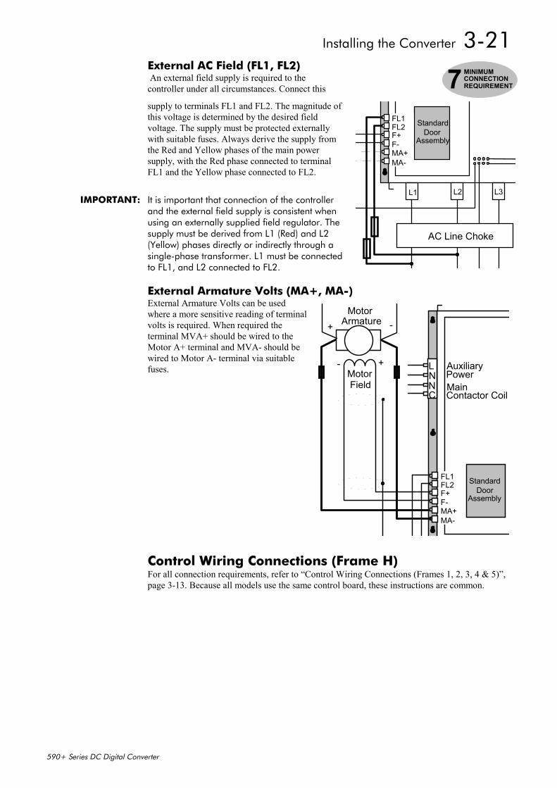
Installing the Converter 3-21
590+ Series DC Digital Converter
External AC Field (FL1, FL2) An external field supply is required to thecontroller under all circumstances. Connect this
supply to terminals FL1 and FL2. The magnitude ofthis voltage is determined by the desired fieldvoltage. The supply must be protected externallywith suitable fuses. Always derive the supply fromthe Red and Yellow phases of the main powersupply, with the Red phase connected to terminalFL1 and the Yellow phase connected to FL2.
IMPORTANT: It is important that connection of the controllerand the external field supply is consistent whenusing an externally supplied field regulator. Thesupply must be derived from L1 (Red) and L2(Yellow) phases directly or indirectly through asingle-phase transformer. L1 must be connectedto FL1, and L2 connected to FL2.
External Armature Volts (MA+, MA-)External Armature Volts can be usedwhere a more sensitive reading of terminalvolts is required. When required theterminal MVA+ should be wired to theMotor A+ terminal and MVA- should bewired to Motor A- terminal via suitablefuses.
Control Wiring Connections (Frame H)For all connection requirements, refer to “Control Wiring Connections (Frames 1, 2, 3, 4 & 5)”,page 3-13. Because all models use the same control board, these instructions are common.
L1 L2 L3
FL1FL2F+F-MA+MA-
StandardDoor
Assembly
AC Line Choke
7MINIMUMCONNECTIONREQUIREMENT
LNNC
FL1FL2F+F-MA+MA-
AuxiliaryPowerMain
-Motor
Armature+
+-MotorField
Contactor Coil
StandardDoor
Assembly
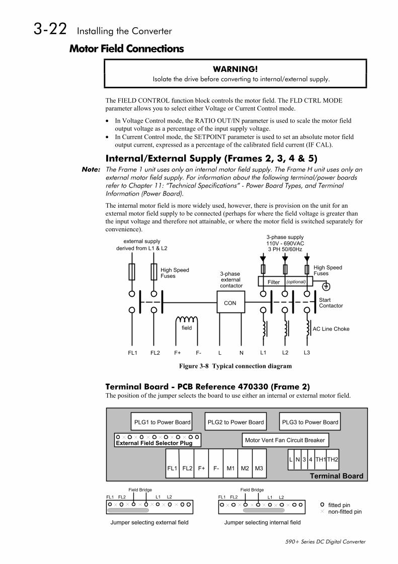
3-22 Installing the Converter
590+ Series DC Digital Converter
Motor Field Connections
WARNING! Isolate the drive before converting to internal/external supply.
The FIELD CONTROL function block controls the motor field. The FLD CTRL MODEparameter allows you to select either Voltage or Current Control mode.
• In Voltage Control mode, the RATIO OUT/IN parameter is used to scale the motor fieldoutput voltage as a percentage of the input supply voltage.
• In Current Control mode, the SETPOINT parameter is used to set an absolute motor fieldoutput current, expressed as a percentage of the calibrated field current (IF CAL).
Internal/External Supply (Frames 2, 3, 4 & 5)Note: The Frame 1 unit uses only an internal motor field supply. The Frame H unit uses only an
external motor field supply. For information about the following terminal/power boardsrefer to Chapter 11: “Technical Specifications” - Power Board Types, and TerminalInformation (Power Board).
The internal motor field is more widely used, however, there is provision on the unit for anexternal motor field supply to be connected (perhaps for where the field voltage is greater thanthe input voltage and therefore not attainable, or where the motor field is switched separately forconvenience).
CON
field
external supplyderived from L1 & L2
FL1 FL2 F+ F- L N L1 L2 L3
Filter
StartContactor
3-phase supply110V - 690VAC
High SpeedFuses
AC Line Choke
3-phase
contactor
3 PH 50/60Hz
(optional)external
High SpeedFuses
Figure 3-8 Typical connection diagram
Terminal Board - PCB Reference 470330 (Frame 2)The position of the jumper selects the board to use either an internal or external motor field.
FL1 FL2 F+ F- M1 M2 M3
Motor Vent Fan Circuit Breaker
PLG1 to Power Board PLG2 to Power Board PLG3 to Power Board
External Field Selector Plug
Terminal Board
L N 3 4 TH1TH2
FL1 FL2Field Bridge Field Bridge
L1 L2
Jumper selecting external field Jumper selecting internal field
L1 L2 FL1 FL2
fitted pinnon-fitted pin
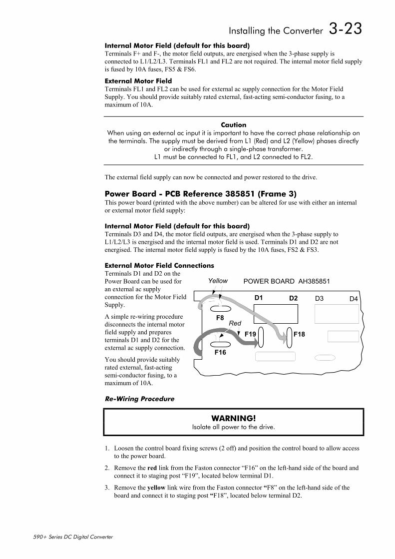
Installing the Converter 3-23
590+ Series DC Digital Converter
Internal Motor Field (default for this board)Terminals F+ and F-, the motor field outputs, are energised when the 3-phase supply isconnected to L1/L2/L3. Terminals FL1 and FL2 are not required. The internal motor field supplyis fused by 10A fuses, FS5 & FS6.
External Motor FieldTerminals FL1 and FL2 can be used for external ac supply connection for the Motor FieldSupply. You should provide suitably rated external, fast-acting semi-conductor fusing, to amaximum of 10A.
Caution When using an external ac input it is important to have the correct phase relationship onthe terminals. The supply must be derived from L1 (Red) and L2 (Yellow) phases directly
or indirectly through a single-phase transformer.L1 must be connected to FL1, and L2 connected to FL2.
The external field supply can now be connected and power restored to the drive.
Power Board - PCB Reference 385851 (Frame 3)This power board (printed with the above number) can be altered for use with either an internalor external motor field supply:
Internal Motor Field (default for this board)Terminals D3 and D4, the motor field outputs, are energised when the 3-phase supply toL1/L2/L3 is energised and the internal motor field is used. Terminals D1 and D2 are notenergised. The internal motor field supply is fused by the 10A fuses, FS2 & FS3.
External Motor Field ConnectionsTerminals D1 and D2 on thePower Board can be used foran external ac supplyconnection for the Motor FieldSupply.
A simple re-wiring proceduredisconnects the internal motorfield supply and preparesterminals D1 and D2 for theexternal ac supply connection.
You should provide suitablyrated external, fast-actingsemi-conductor fusing, to amaximum of 10A.
Re-Wiring Procedure
WARNING! Isolate all power to the drive.
1. Loosen the control board fixing screws (2 off) and position the control board to allow accessto the power board.
2. Remove the red link from the Faston connector “F16” on the left-hand side of the board andconnect it to staging post “F19”, located below terminal D1.
3. Remove the yellow link wire from the Faston connector “F8” on the left-hand side of theboard and connect it to staging post “F18”, located below terminal D2.
POWER BOARD AH385851
D1 D2 D3 D4
RedF8
F16
Yellow
F18F19
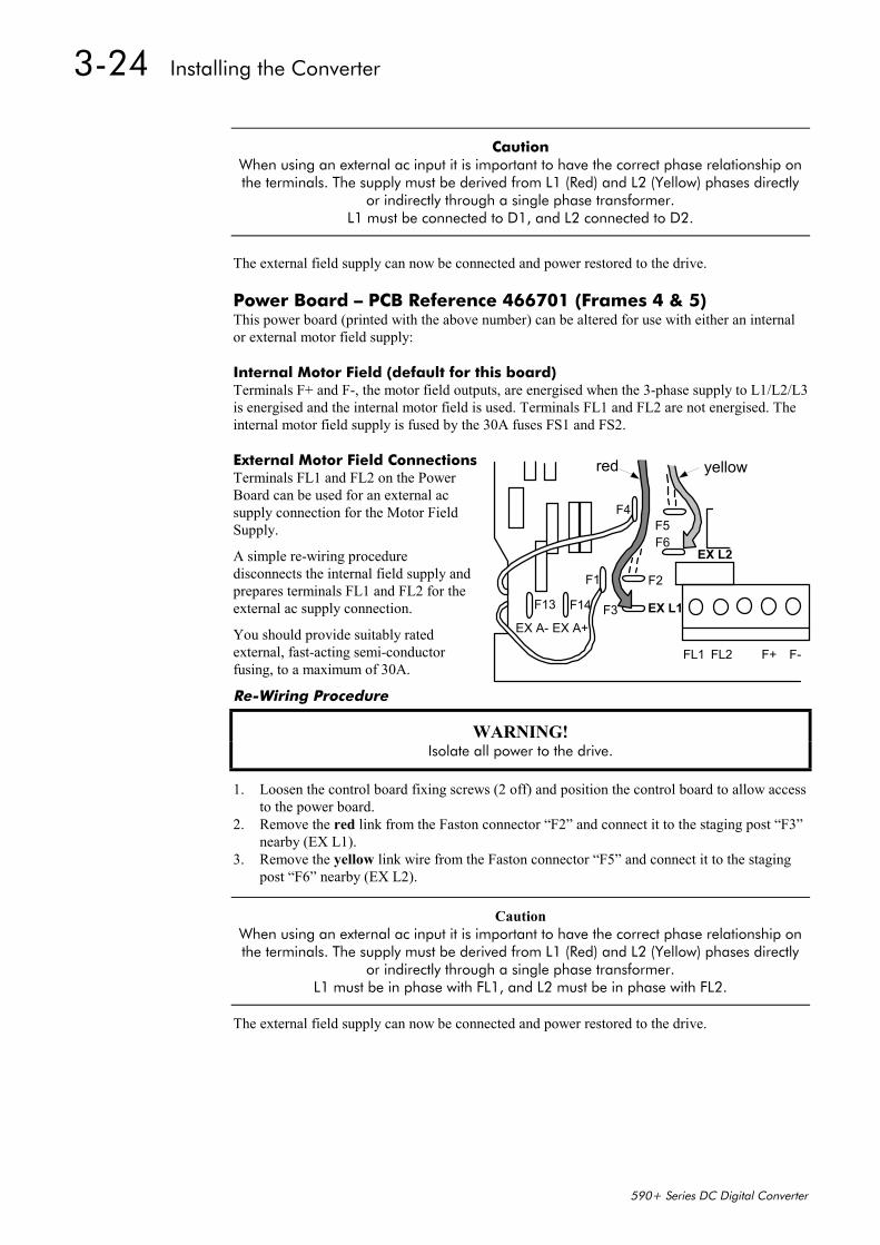
3-24 Installing the Converter
590+ Series DC Digital Converter
Caution When using an external ac input it is important to have the correct phase relationship onthe terminals. The supply must be derived from L1 (Red) and L2 (Yellow) phases directly
or indirectly through a single phase transformer.L1 must be connected to D1, and L2 connected to D2.
The external field supply can now be connected and power restored to the drive.
Power Board – PCB Reference 466701 (Frames 4 & 5)This power board (printed with the above number) can be altered for use with either an internalor external motor field supply:
Internal Motor Field (default for this board)Terminals F+ and F-, the motor field outputs, are energised when the 3-phase supply to L1/L2/L3is energised and the internal motor field is used. Terminals FL1 and FL2 are not energised. Theinternal motor field supply is fused by the 30A fuses FS1 and FS2.
External Motor Field ConnectionsTerminals FL1 and FL2 on the PowerBoard can be used for an external acsupply connection for the Motor FieldSupply.
A simple re-wiring proceduredisconnects the internal field supply andprepares terminals FL1 and FL2 for theexternal ac supply connection.
You should provide suitably ratedexternal, fast-acting semi-conductorfusing, to a maximum of 30A.
Re-Wiring Procedure
WARNING! Isolate all power to the drive.
1. Loosen the control board fixing screws (2 off) and position the control board to allow accessto the power board.
2. Remove the red link from the Faston connector “F2” and connect it to the staging post “F3”nearby (EX L1).
3. Remove the yellow link wire from the Faston connector “F5” and connect it to the stagingpost “F6” nearby (EX L2).
Caution When using an external ac input it is important to have the correct phase relationship onthe terminals. The supply must be derived from L1 (Red) and L2 (Yellow) phases directly
or indirectly through a single phase transformer.L1 must be in phase with FL1, and L2 must be in phase with FL2.
The external field supply can now be connected and power restored to the drive.
F1
F13 F14 F3
F6
F4
F2
F5
FL1 FL2 F+ F-
yellowred
EX A- EX A+EX L1
EX L2
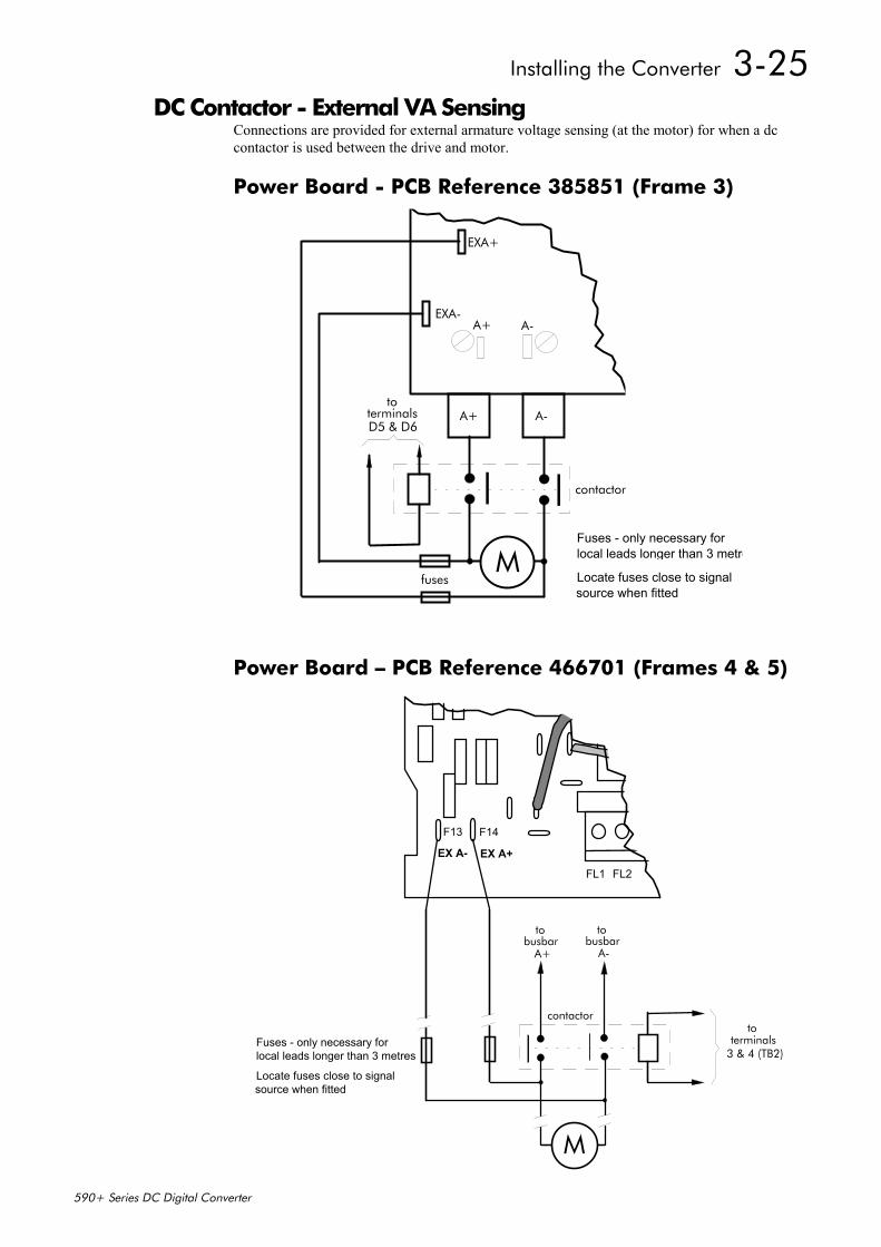
Installing the Converter 3-25
590+ Series DC Digital Converter
DC Contactor - External VA SensingConnections are provided for external armature voltage sensing (at the motor) for when a dccontactor is used between the drive and motor.
Power Board - PCB Reference 385851 (Frame 3)
EXA-
EXA+
A+ A-
A+ A- L1
FS2
FL1
(F15)
M
contactor
toterminalsD5 & D6
fuses
Fuses - only necessary forlocal leads longer than 3 metre
Locate fuses close to signalsource when fitted
Power Board – PCB Reference 466701 (Frames 4 & 5)
F13 F14
FL1 FL2 F+ F-
Fuses - only necessary forlocal leads longer than 3 metres
contactorto
terminals3 & 4 (TB2)
M
A- A+
tobusbar
tobusbar
Locate fuses close to signalsource when fitted
EX A- EX A+
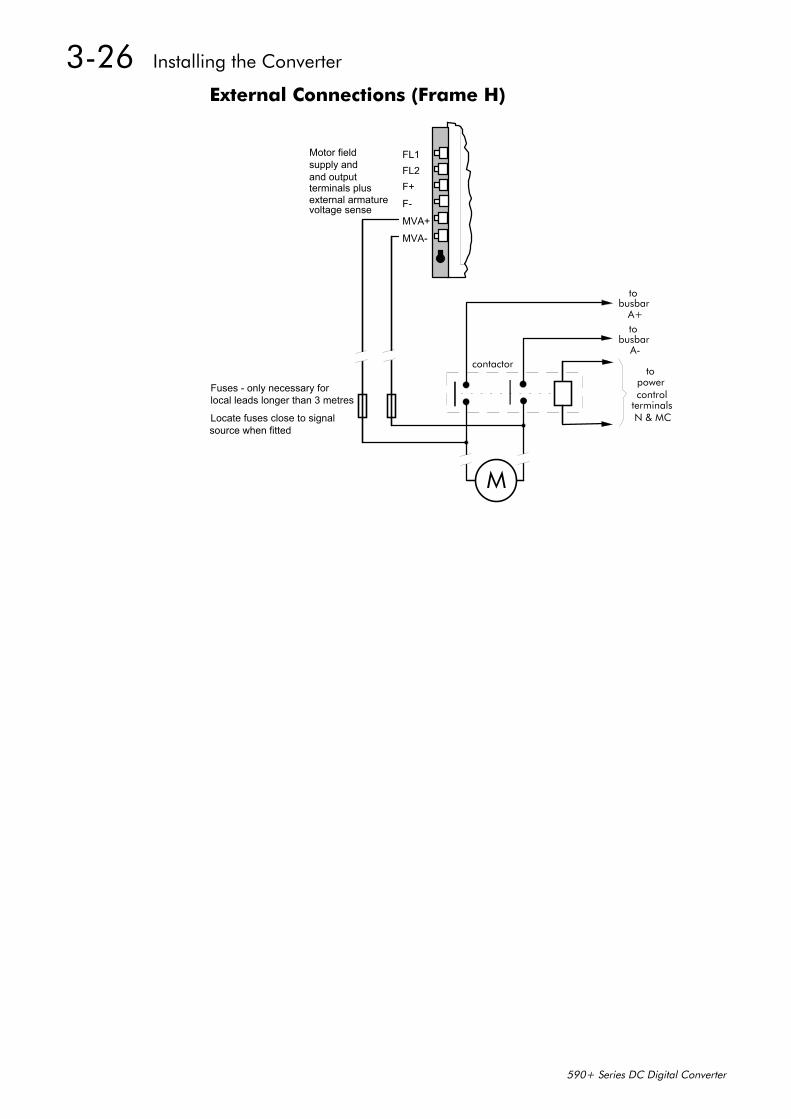
3-26 Installing the Converter
590+ Series DC Digital Converter
External Connections (Frame H)
Fuses - only necessary forlocal leads longer than 3 metres
contactorto
terminalsN & MC
M
A+
tobusbar
A-
tobusbar
Locate fuses close to signalsource when fitted
FL1FL2F+F-
MVA+
MVA-
supply and and outputterminals plusexternal armaturevoltage sense
Motor field
powercontrol
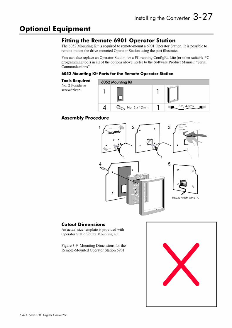
Installing the Converter 3-27
590+ Series DC Digital Converter
Optional Equipment
Fitting the Remote 6901 Operator StationThe 6052 Mounting Kit is required to remote-mount a 6901 Operator Station. It is possible toremote-mount the drive-mounted Operator Station using the port illustrated
You can also replace an Operator Station for a PC running ConfigEd Lite (or other suitable PCprogramming tool) in all of the options above. Refer to the Software Product Manual: “SerialCommunications”.
6052 Mounting Kit Parts for the Remote Operator Station
Tools RequiredNo. 2 Posidrivescrewdriver.
Assembly Procedure
Cutout DimensionsAn actual size template is provided withOperator Station/6052 Mounting Kit.
Figure 3-9 Mounting Dimensions for theRemote-Mounted Operator Station 6901
1 1
4 1
6052 Mounting Kit6052 Mounting Kit6052 Mounting Kit6052 Mounting Kit
No. 6 x 12mm 3m, 4-way
2 3
RS232 / REM OP STA
5
1
4
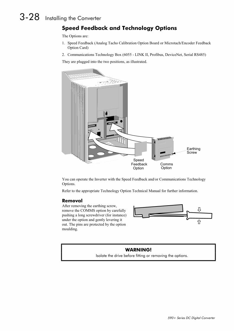
3-28 Installing the Converter
590+ Series DC Digital Converter
Speed Feedback and Technology OptionsThe Options are:
1. Speed Feedback (Analog Tacho Calibration Option Board or Microtach/Encoder FeedbackOption Card)
2. Communications Technology Box (6055 - LINK II, Profibus, DeviceNet, Serial RS485)
They are plugged into the two positions, as illustrated.
CommsOption
FeedbackOption
Speed
EarthingScrew
You can operate the Inverter with the Speed Feedback and/or Communications TechnologyOptions.
Refer to the appropriate Technology Option Technical Manual for further information.
RemovalAfter removing the earthing screw,remove the COMMS option by carefullypushing a long screwdriver (for instance)under the option and gently levering itout. The pins are protected by the optionmoulding.
WARNING! Isolate the drive before fitting or removing the options.
Installing the Converter 3-29
590+ Series DC Digital Converter
External AC Supply EMC Filter InstallationRefer to Chapter 11: “Technical Specifications” - Environmental Details, and External ACSupply (RFI) Filters and Line Choke for selection details.
A filter is used with the Converter to reduce the line conducted emissions produced by theConverter. Filters are used in parallel on the higher current Converters. When installed correctlyand used with the specified 2% minimum line chokes, conformance with EN55011 Class A canbe achieved (suitable for both generic environments: RF Emission and Immunity).
Cubicle-Mounting the 590+ Converter with Filter
WARNING! Do not touch filter terminals or cabling for at least 3 minutes after removing the ac
supply.
Only use the ac supply filter with a permanent earth connection.
The filter should be fitted on the mains side of the contactor.
The Converter must be mounted vertically on a solid, flat, vertical surface. It must be installedinto a cubicle.
The recommended EMC filter is mounted to the left, right, above, below, or spaced behind theConverter. It can be mounted flat against the surface, or projecting out from the surface if thefilter type has side fixings.
1. Mount the filter securely at the four fixing points (flat or on its side).
2. Mount the Converter next to the filter, allowing for the required airgap between theConverter, the filter and any adjacent equipment.
Connection DetailsThe connection between the Converter, choke and filter must always be as short as possible andmust be segregated from all other cables. Ideally, mount the filter and choke onto the samemetallic panel as the Converter. Take care not to obstruct any ventilation spacing.
If this cable/busbar exceeds 0.6m (2 feet) in length, it must be replaced with a screened/armouredcable. The screen/armour must be earthed at both the filter, choke and Converter ends with large-area contact surfaces, preferably with metal cable glands.
You should enhance the RF connection between the Converter, choke, filter and panel asfollows:
1. Remove any paint/insulation between the mounting points of the EMC filter, choke,Converter and the panel. Liberally apply petroleum jelly over the mounting points andsecuring threads. This will prevent corrosion. Alternatively, conducting paint could be usedon the panel.
2. If 1 above is not possible, then improve the RF earth bond between the filter and Converterby making an additional RF earth connection. Use wire braid of at least 10mm² cross-sectional area.
Note: Metal surfaces, such as anodised or yellow chromed (with cable mounting or 35mm DINrails, screws and bolts) have a high impedance which can be very detrimental to EMCperformance.
3. A low RF impedance path must be provided between the motor frame and back panel onwhich the drive, choke and EMC filters are mounted. This low impedance RF path shouldfollow the path of the motor cables in order to minimise the loop area. Failure to do so willresult in increased conducted emissions.A low RF impedance path will normally be achieved by:
Bonding the armour of the motor supply cables at one end to the motor frame, and at the

3-30 Installing the Converter
590+ Series DC Digital Converter
other end to the cubicle back panel. Ideally 360o bonding is required, which can be achievedwith cable glands, refer to Figure 3-5 360 Degree Screened Connection, page 3-6. Ensuring that conduit containing the motor supply cables are bonded together using braid.
The conduit should also be bonded to the motor frame and the cubicle back panel.
Earthing DetailsThe protective earth (PE) conductor exiting the filter must be connected to the protective earthconnection of the Converter. Any additional RF earth, such as a cable screen, is not a protectiveearth. The EMC filter must be permanently earthed to prevent the risk of electric shock underabnormal operating instances (such as the loss of one phase of the ac supply).
You can achieve permanent earthing by either:
• using a copper protective earth conductor of at least 10mm²
• installing a second conductor, in parallel connection with the protective conductor, to aseparate protective earth terminal
Each conductor must independently meet the requirements for a protective earth conductor.
Operating ConditionsThe recommended EMC filters operate from normal three-phases supplies which are balancedwith respect to earth (earth referenced supplies - TN). This minimises the earth leakage currentdue to the filter capacitors between phase and earth.
IMPORTANT: We do not recommend the use of ac supply filters on non earth-referenced supplies - IT.The supplies cause earth leakage currents to increase, and interfere with the operation ofearth fault monitoring equipment. In addition, EMC performance of the filter is degraded.
As with all power electronic drives, conducted emissions increase with motor cable length. EMCconformance is only guaranteed up to a cable length of 50m. The cable length can be increased.Refer to Eurotherm Drives for more information.
Earth Fault Monitoring Systems
WARNING! Circuit breakers used with VSDs and other similar equipment are not suitable for
personnel protection. Use another means to provide personal safety. Refer toEN50178 (1998) / VDE0160 (1994) / EN60204-1 (1994)
We do not recommend the use of circuit breakers (e.g. RCD, ELCB, GFCI), but where their useis mandatory, they should:
• Operate correctly with dc and ac protective earth currents (i.e. type B RCDs as inAmendment 2 of IEC755).
• Have adjustable trip amplitude and time characteristics to prevent nuisance tripping onswitch-on.
Note: When the ac supply is switched on, a pulse of current flows to earth to charge the EMCfilter internal capacitors which are connected between phase and earth. This has beenminimised in Eurotherm Drives filters, but may still trip out any circuit breaker in the earthsystem. In addition, high frequency and dc components of earth leakage currents will flowunder normal operating conditions. Under certain fault conditions larger dc protectiveearth currents may flow. The protective function of some circuit breakers cannot beguaranteed under such operating conditions.
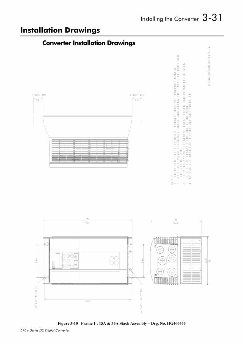
Installing the Converter 3-31
590+ Series DC Digital Converter
Installation Drawings
Converter Installation Drawings
Figure 3-10 Frame 1 : 15A & 35A Stack Assembly – Drg. No. HG466465
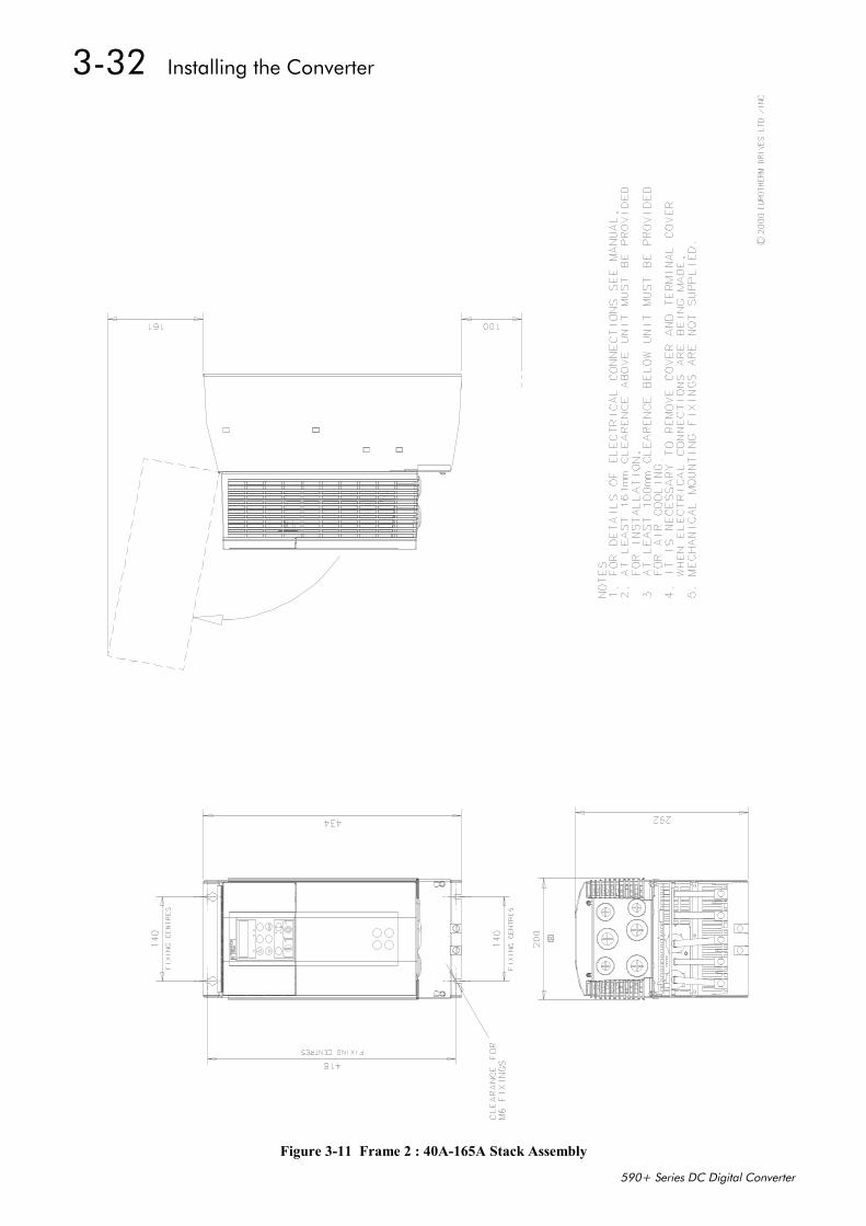
3-32 Installing the Converter
590+ Series DC Digital Converter
Figure 3-11 Frame 2 : 40A-165A Stack Assembly
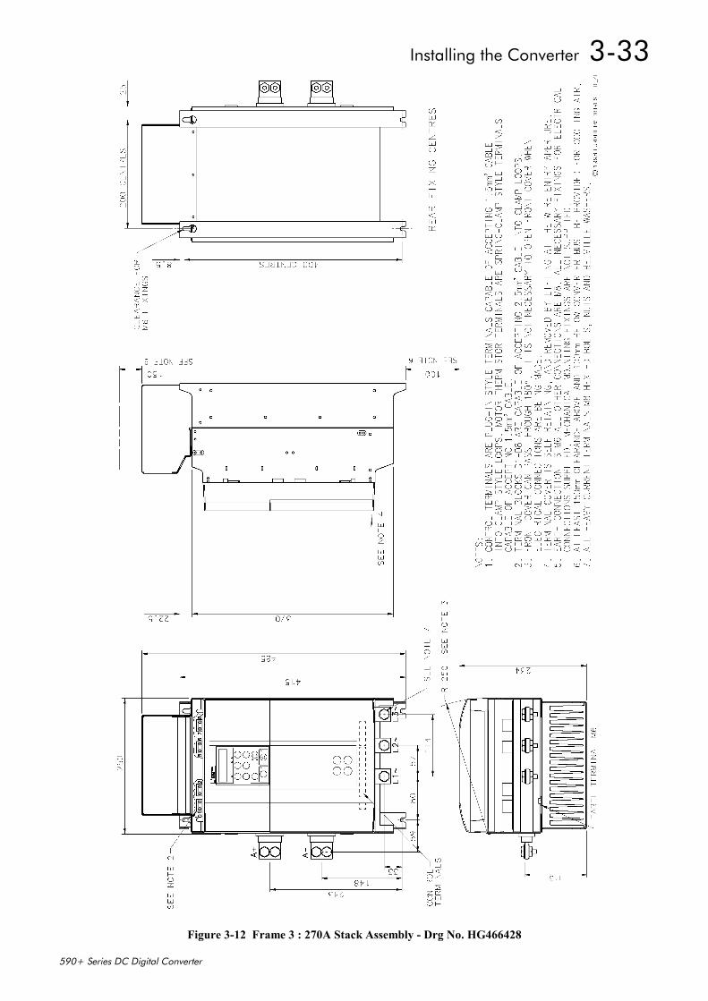
Installing the Converter 3-33
590+ Series DC Digital Converter
Figure 3-12 Frame 3 : 270A Stack Assembly - Drg No. HG466428
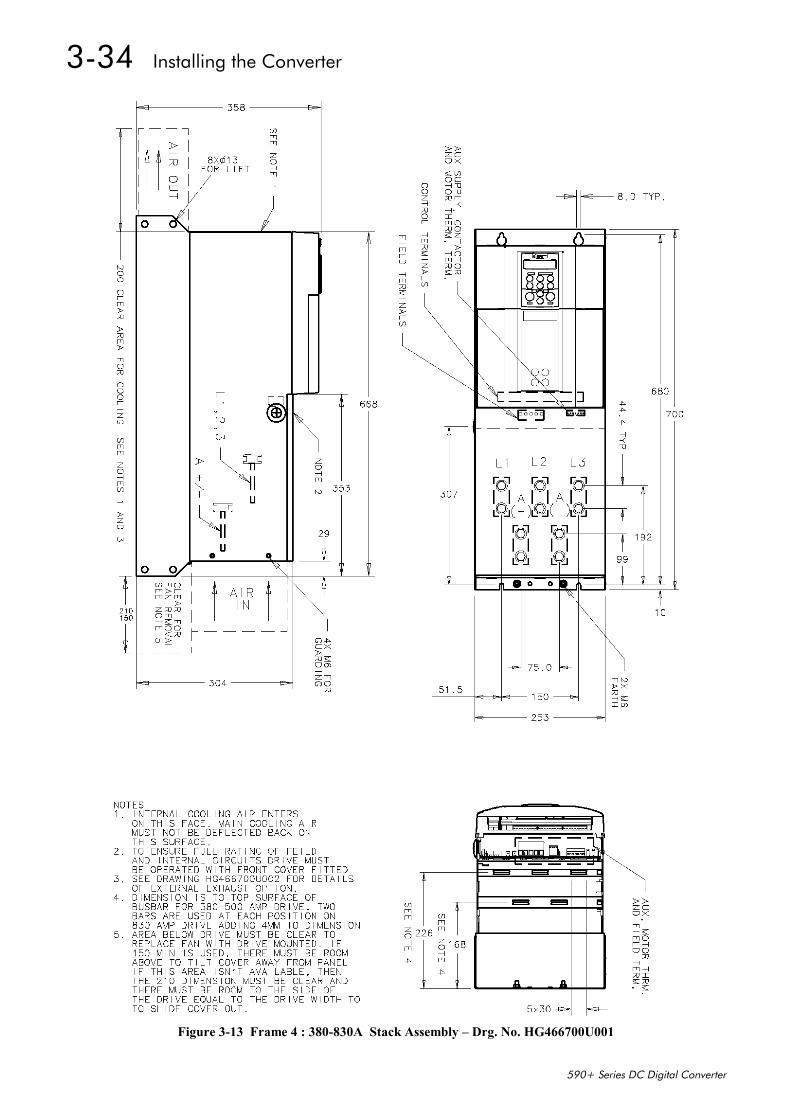
3-34 Installing the Converter
590+ Series DC Digital Converter
Figure 3-13 Frame 4 : 380-830A Stack Assembly – Drg. No. HG466700U001
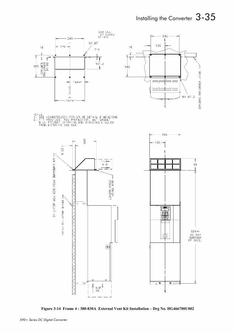
Installing the Converter 3-35
590+ Series DC Digital Converter
Figure 3-14 Frame 4 : 380-830A External Vent Kit Installation – Drg No. HG466700U002
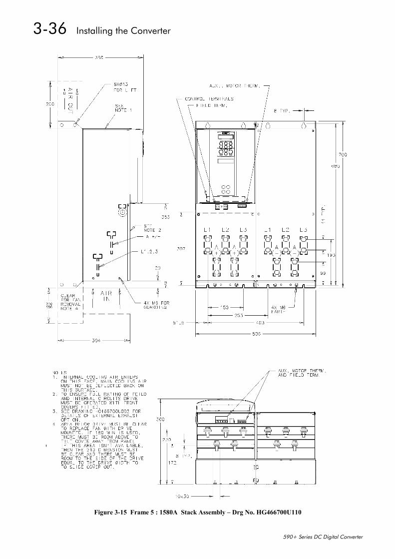
3-36 Installing the Converter
590+ Series DC Digital Converter
Figure 3-15 Frame 5 : 1580A Stack Assembly – Drg No. HG466700U110
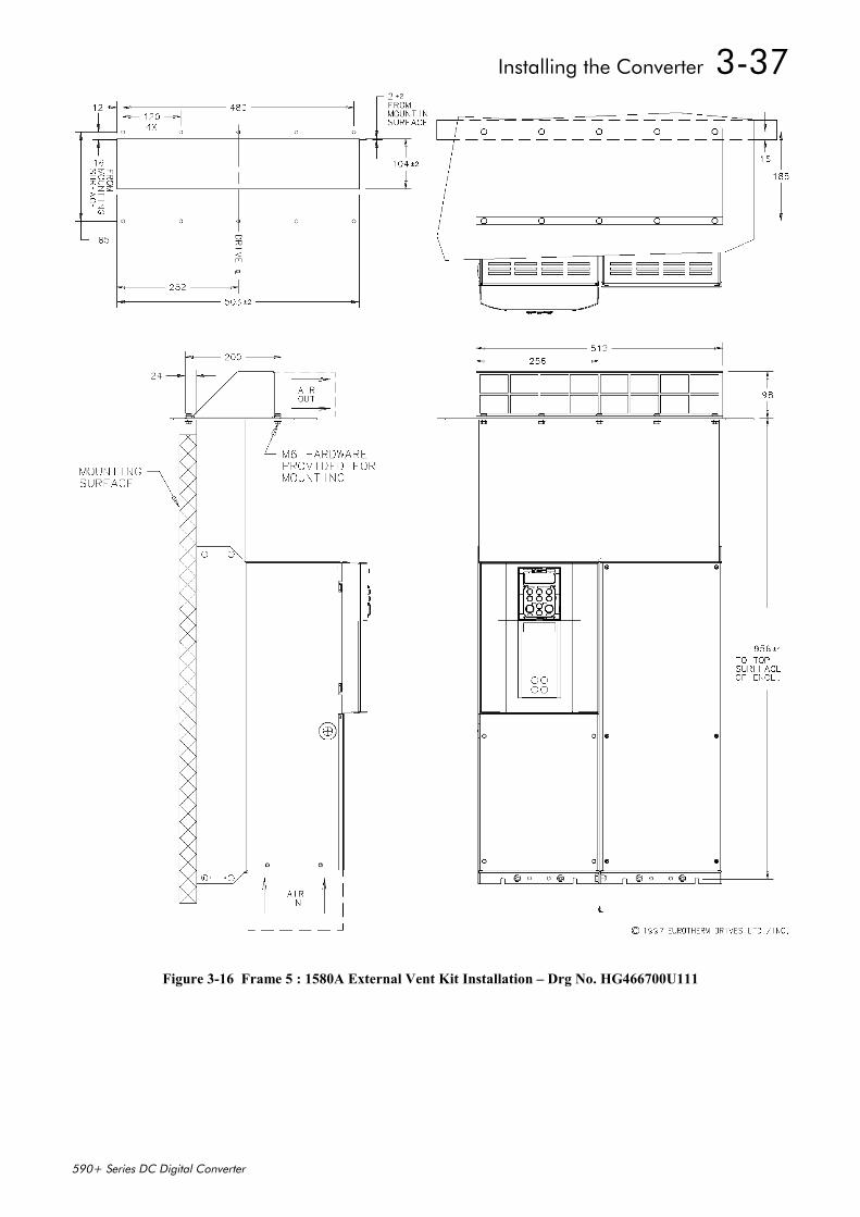
Installing the Converter 3-37
590+ Series DC Digital Converter
Figure 3-16 Frame 5 : 1580A External Vent Kit Installation – Drg No. HG466700U111
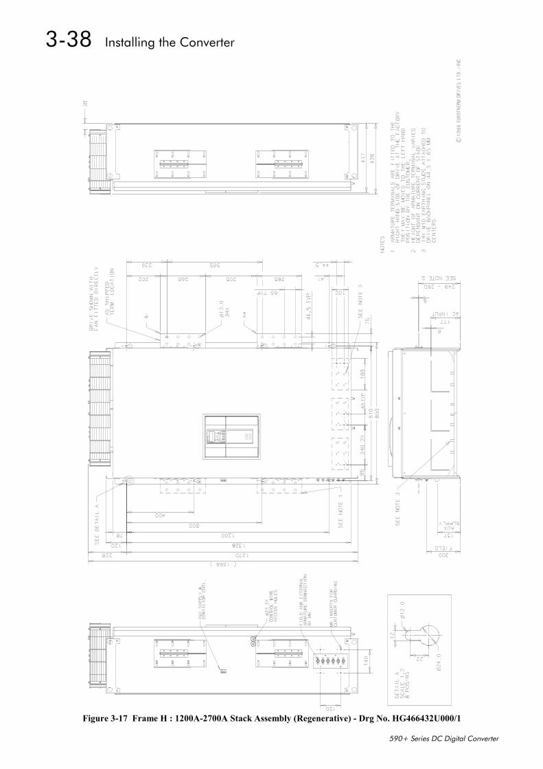
3-38 Installing the Converter
590+ Series DC Digital Converter
Figure 3-17 Frame H : 1200A-2700A Stack Assembly (Regenerative) - Drg No. HG466432U000/1
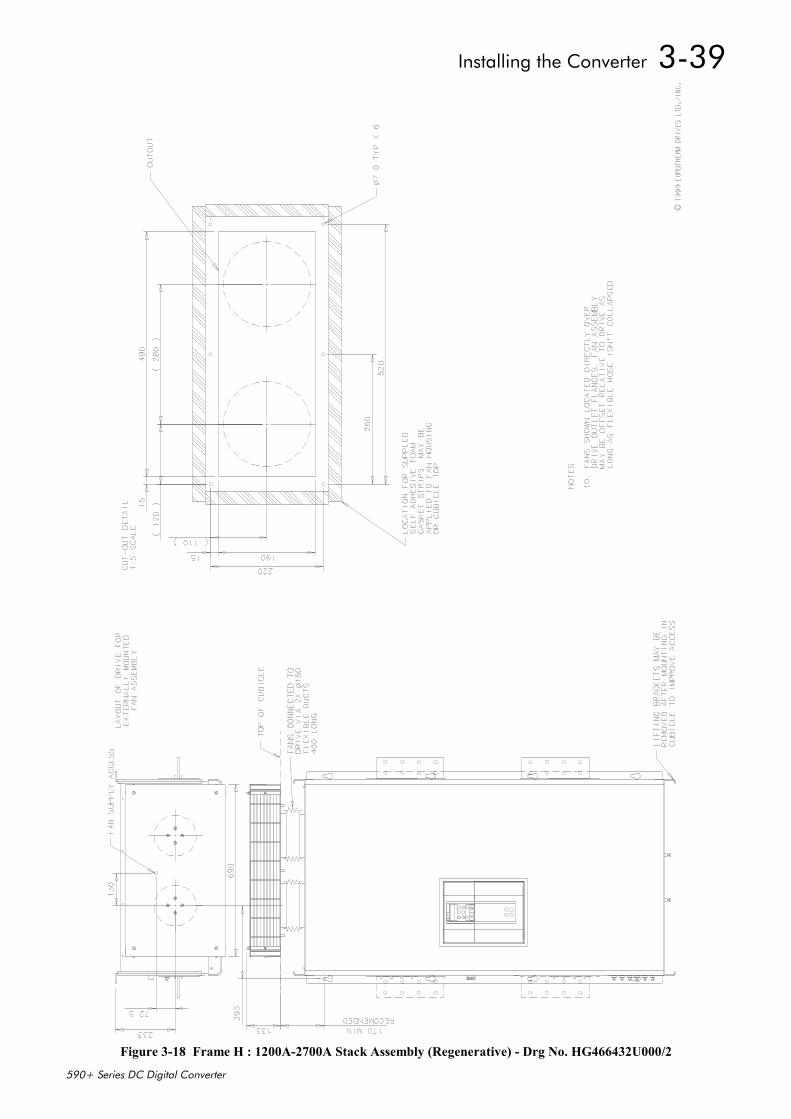
Installing the Converter 3-39
590+ Series DC Digital Converter
Figure 3-18 Frame H : 1200A-2700A Stack Assembly (Regenerative) - Drg No. HG466432U000/2
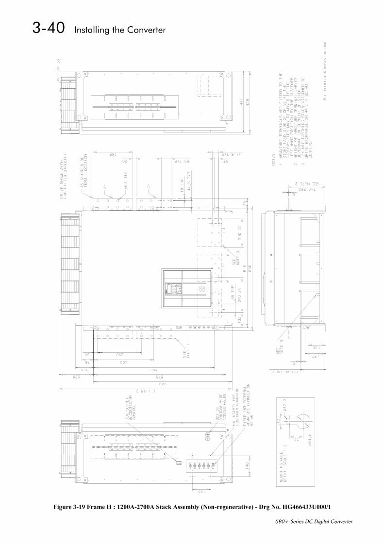
3-40 Installing the Converter
590+ Series DC Digital Converter
Figure 3-19 Frame H : 1200A-2700A Stack Assembly (Non-regenerative) - Drg No. HG466433U000/1
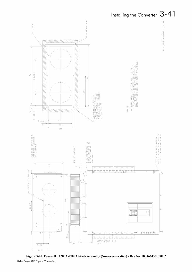
Installing the Converter 3-41
590+ Series DC Digital Converter
Figure 3-20 Frame H : 1200A-2700A Stack Assembly (Non-regenerative) - Drg No. HG466433U000/2
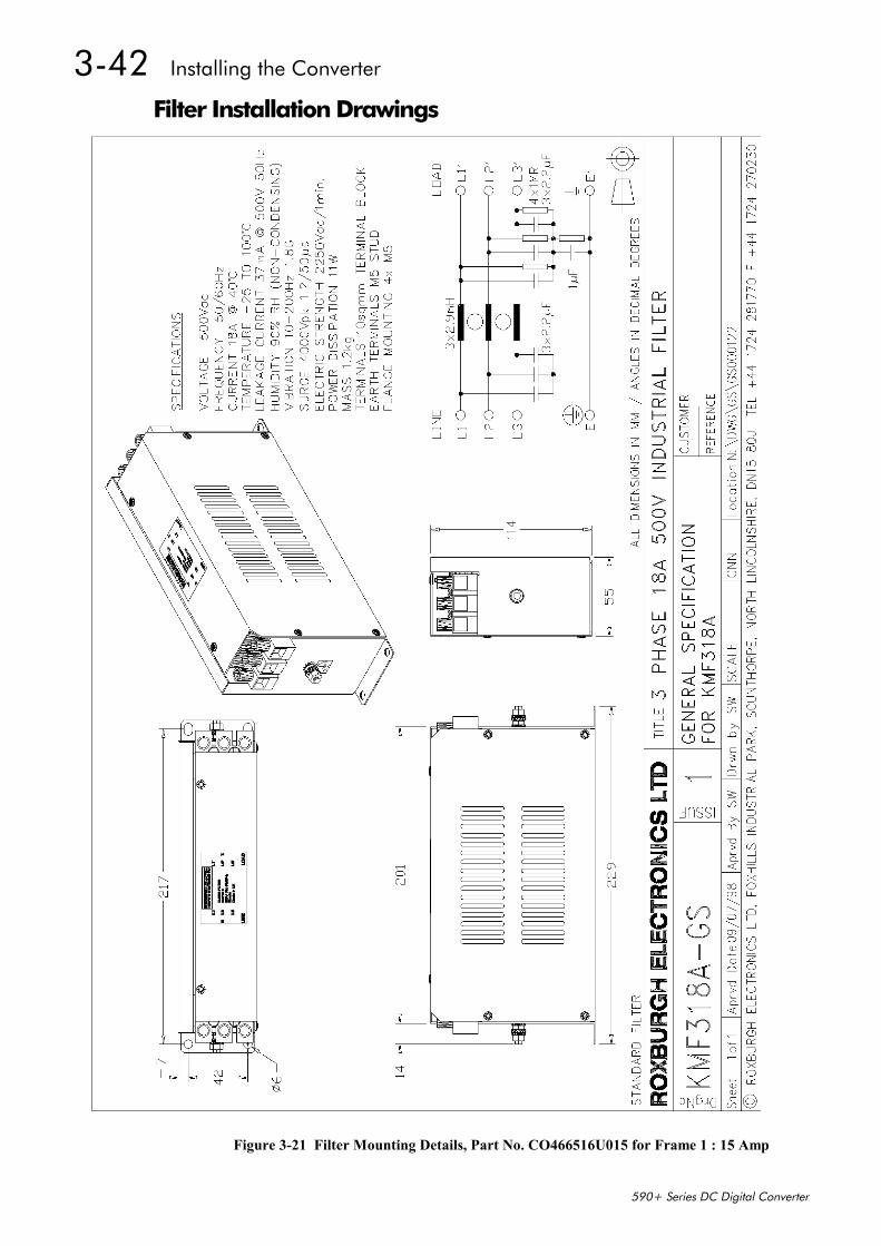
3-42 Installing the Converter
590+ Series DC Digital Converter
Filter Installation Drawings
Figure 3-21 Filter Mounting Details, Part No. CO466516U015 for Frame 1 : 15 Amp
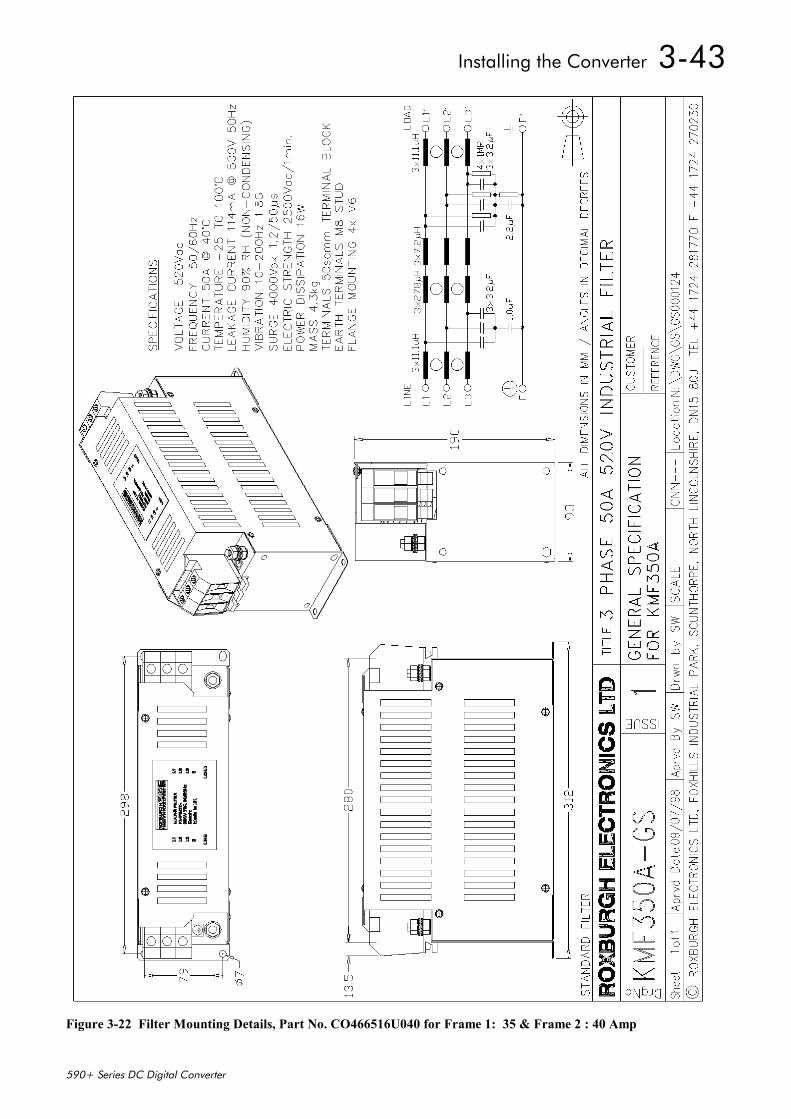
Installing the Converter 3-43
590+ Series DC Digital Converter
Figure 3-22 Filter Mounting Details, Part No. CO466516U040 for Frame 1: 35 & Frame 2 : 40 Amp
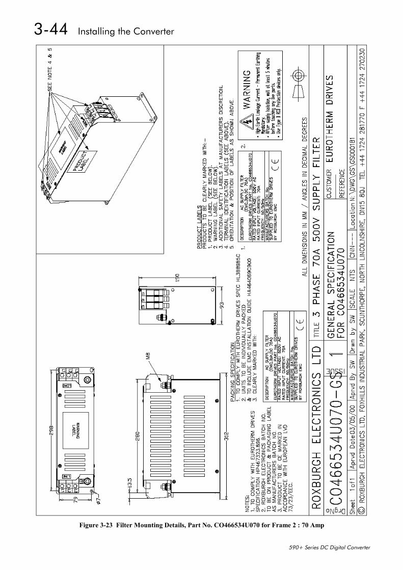
3-44 Installing the Converter
590+ Series DC Digital Converter
Figure 3-23 Filter Mounting Details, Part No. CO466534U070 for Frame 2 : 70 Amp
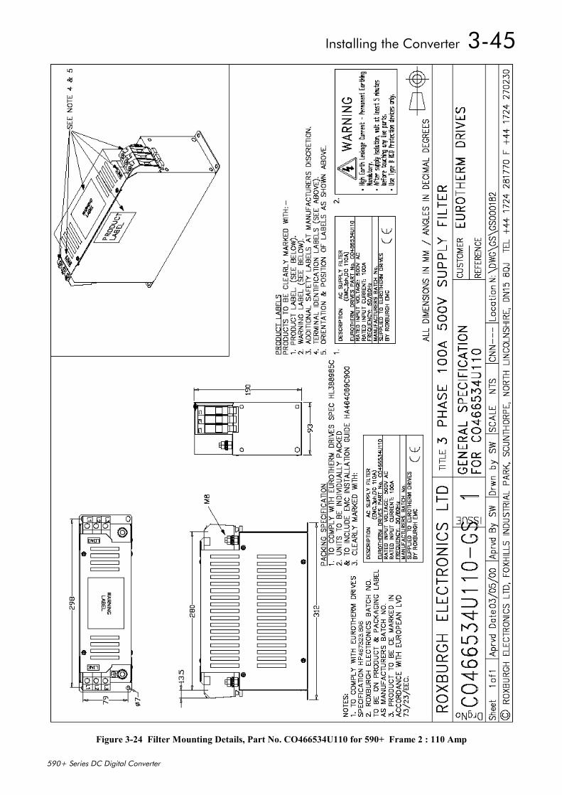
Installing the Converter 3-45
590+ Series DC Digital Converter
Figure 3-24 Filter Mounting Details, Part No. CO466534U110 for 590+ Frame 2 : 110 Amp
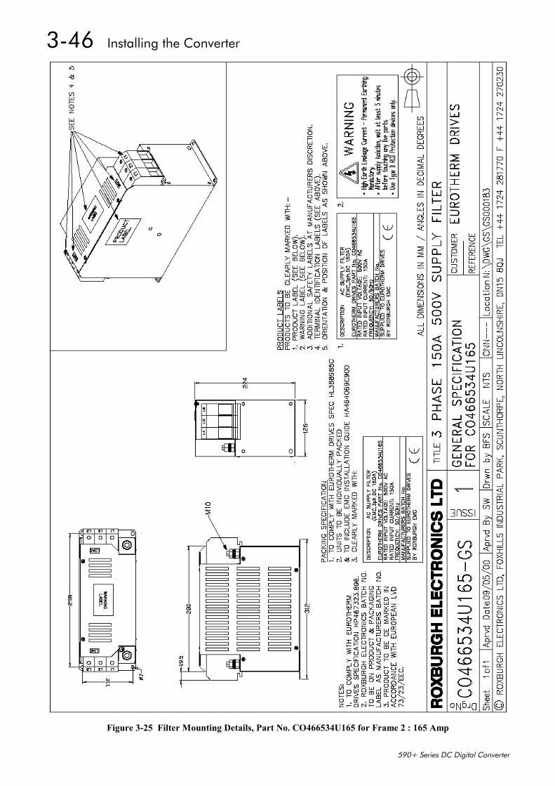
3-46 Installing the Converter
590+ Series DC Digital Converter
Figure 3-25 Filter Mounting Details, Part No. CO466534U165 for Frame 2 : 165 Amp
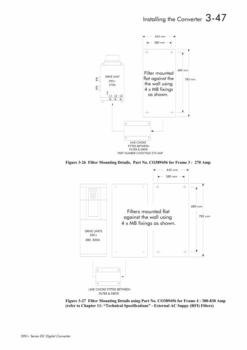
Installing the Converter 3-47
590+ Series DC Digital Converter
L1 L2 L3E
DRIVE UNIT
590+270A
FITTED BETWEENFILTER & DRIVE
PART NUMBER CO057960 270 AMP
LINE CHOKE
380 mm
445 mm
680 mm
785 mm
Filter mountedflat against the
4 x M8 fixingsthe wall using
as shown.
Figure 3-26 Filter Mounting Details, Part No. CO389456 for Frame 3 : 270 Amp
590+DRIVE UNITS
FILTER & DRIVELINE CHOKE FITTED BETWEEN
Filters mounted flatagainst the wall using
4 x M8 fixings as shown.
380 mm
445 mm
680 mm
785 mm
380 -830A
Figure 3-27 Filter Mounting Details using Part No. CO389456 for Frame 4 : 380-830 Amp(refer to Chapter 11: “Technical Specifications” - External AC Suppy (RFI) Filters)
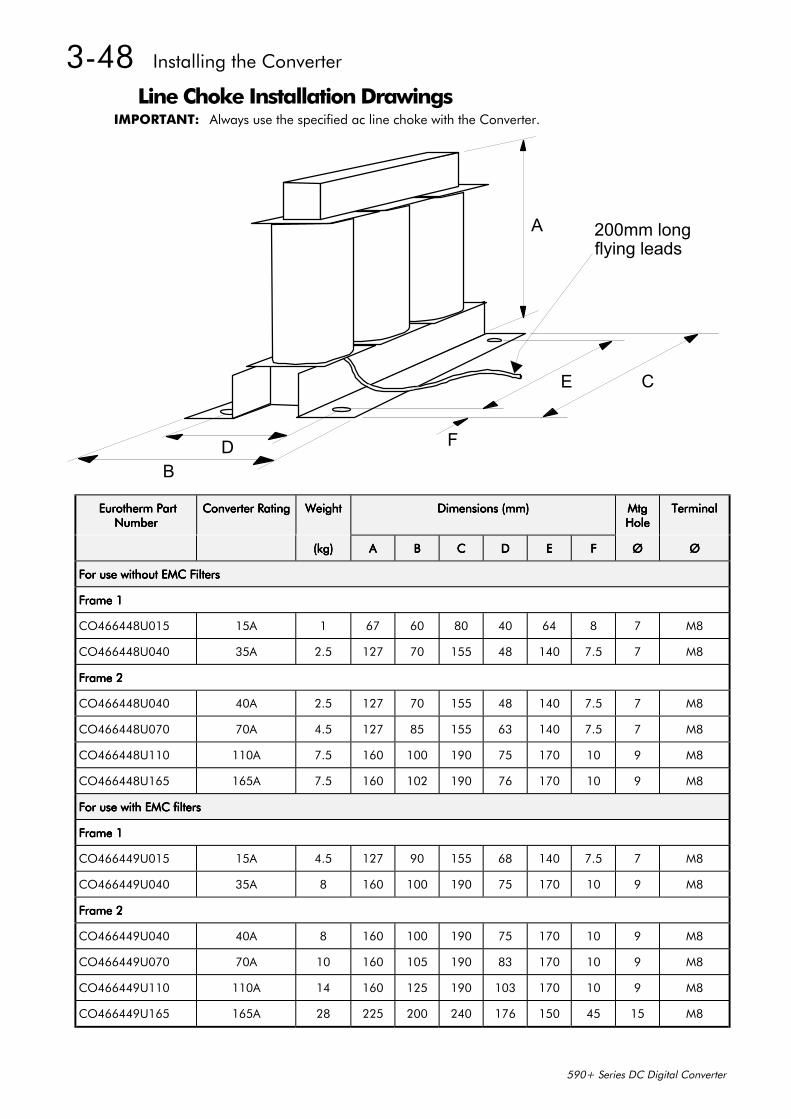
3-48 Installing the Converter
590+ Series DC Digital Converter
Line Choke Installation DrawingsIMPORTANT: Always use the specified ac line choke with the Converter.
BD
A
E C
F
200mm longflying leads
Eurotherm Part Eurotherm Part Eurotherm Part Eurotherm PartNumberNumberNumberNumber
Converter RatingConverter RatingConverter RatingConverter Rating WeightWeightWeightWeight Dimensions (mm)Dimensions (mm)Dimensions (mm)Dimensions (mm) MtgMtgMtgMtgHoleHoleHoleHole
TerminalTerminalTerminalTerminal
(kg)(kg)(kg)(kg) AAAA BBBB CCCC DDDD EEEE FFFF ØØØØ ØØØØ
For use without EMC FiltersFor use without EMC FiltersFor use without EMC FiltersFor use without EMC Filters
Frame 1Frame 1Frame 1Frame 1
CO466448U015 15A 1 67 60 80 40 64 8 7 M8
CO466448U040 35A 2.5 127 70 155 48 140 7.5 7 M8
Frame 2Frame 2Frame 2Frame 2
CO466448U040 40A 2.5 127 70 155 48 140 7.5 7 M8
CO466448U070 70A 4.5 127 85 155 63 140 7.5 7 M8
CO466448U110 110A 7.5 160 100 190 75 170 10 9 M8
CO466448U165 165A 7.5 160 102 190 76 170 10 9 M8
For use with EMC filtersFor use with EMC filtersFor use with EMC filtersFor use with EMC filters
Frame 1Frame 1Frame 1Frame 1
CO466449U015 15A 4.5 127 90 155 68 140 7.5 7 M8
CO466449U040 35A 8 160 100 190 75 170 10 9 M8
Frame 2Frame 2Frame 2Frame 2
CO466449U040 40A 8 160 100 190 75 170 10 9 M8
CO466449U070 70A 10 160 105 190 83 170 10 9 M8
CO466449U110 110A 14 160 125 190 103 170 10 9 M8
CO466449U165 165A 28 225 200 240 176 150 45 15 M8
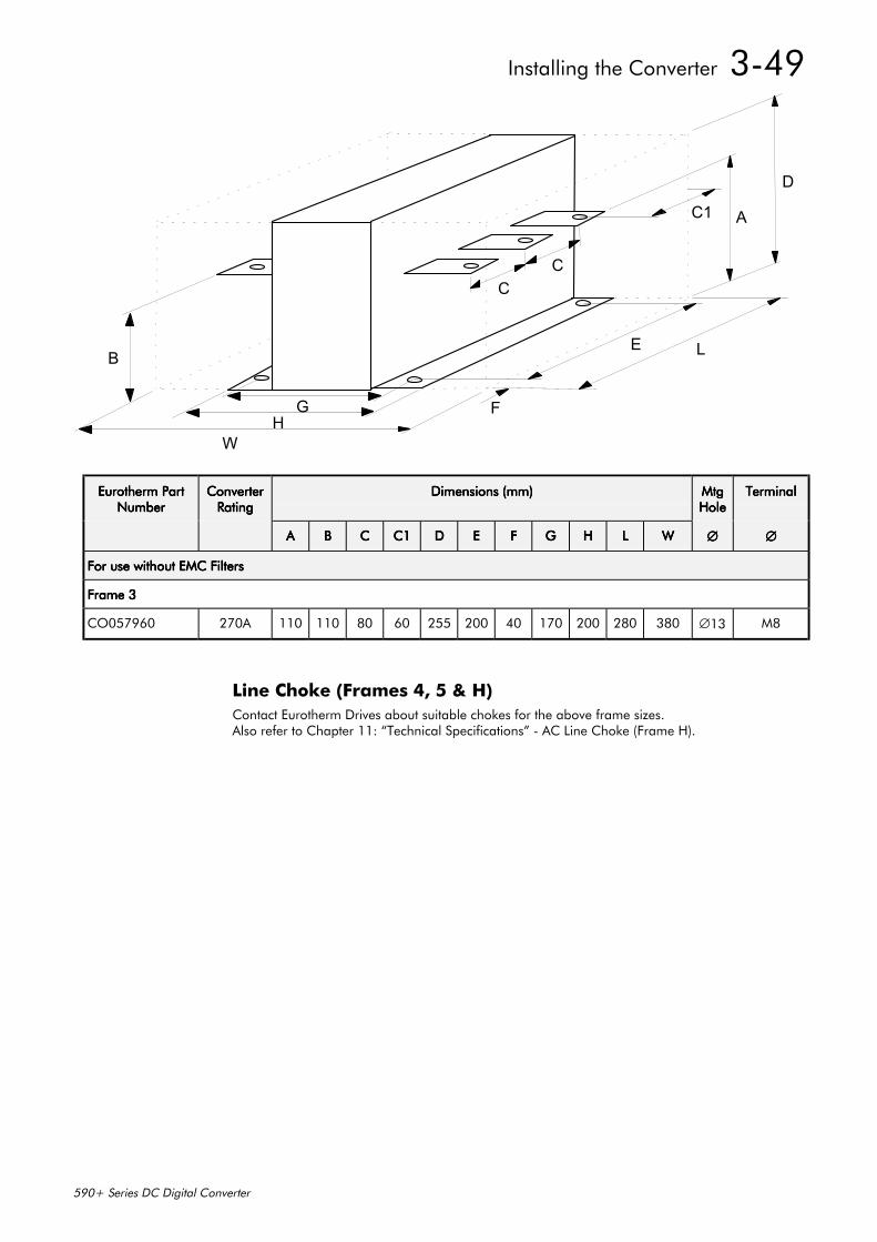
Installing the Converter 3-49
590+ Series DC Digital Converter
WH
G
B
CC
C1 A
D
E L
F
Eurotherm PartEurotherm PartEurotherm PartEurotherm PartNumberNumberNumberNumber
ConverterConverterConverterConverterRatingRatingRatingRating
Dimensions (mm)Dimensions (mm)Dimensions (mm)Dimensions (mm) MtgMtgMtgMtgHoleHoleHoleHole
TerminalTerminalTerminalTerminal
AAAA BBBB CCCC C1C1C1C1 DDDD EEEE FFFF GGGG HHHH LLLL WWWW ∅∅∅∅ ∅∅∅∅
For use without EMC FiltersFor use without EMC FiltersFor use without EMC FiltersFor use without EMC Filters
Frame 3Frame 3Frame 3Frame 3
CO057960 270A 110 110 80 60 255 200 40 170 200 280 380 ∅13 M8
Line Choke (Frames 4, 5 & H)Contact Eurotherm Drives about suitable chokes for the above frame sizes.Also refer to Chapter 11: “Technical Specifications” - AC Line Choke (Frame H).

3-50 Installing the Converter
590+ Series DC Digital Converter

Operating the Converter 4-1
590+ Series DC Digital Converter
4 6OPERATING THE CONVERTER
Pre-Operation Checks
Initial checks before applying power:• Mains power supply voltage is correct.
• Auxiliary power supply voltage is correct.
• Motor is of correct armature voltage and current rating.
• Check all external wiring circuits - power, control, motor and earth connections.
Note: Completely disconnect the Converter before point-to-point checking with a buzzer, orwhen checking insulation with a Megger.
• Check for damage to equipment.
• Check for loose ends, clippings, drilling swarf etc. lodged in the Converter and system.
• If possible check that the motor can be turned freely, and that any cooling fans are intact andfree from obstruction.
Ensure the safety of the complete system before the Converter is energised:• Ensure that rotation of the motor in either direction will not cause damage.
• Ensure that nobody else is working on another part of the system which will be affected bypowering up.
• Ensure that other equipment will not be adversely affected by powering up.
Prepare to energise the Converter and system as follows:• Remove the main external HRC fuses to prevent the main 3-phase and single phase auxiliary
supply from being connected.
• Disconnect the load from the motor shaft, if possible.
• If any of the Converter’s control terminals are not being used, check whether these unusedterminals need to be tied high or low. Refer to Chapter 11: “Technical Specifications”-Control Terminals.
• If there is any doubt about the integrity of a particular installation, insert a high wattageresistor, i.e. fire elements, in series with the motor armature.
• Check external run contacts are open.
• Check external speed setpoints are all zero.
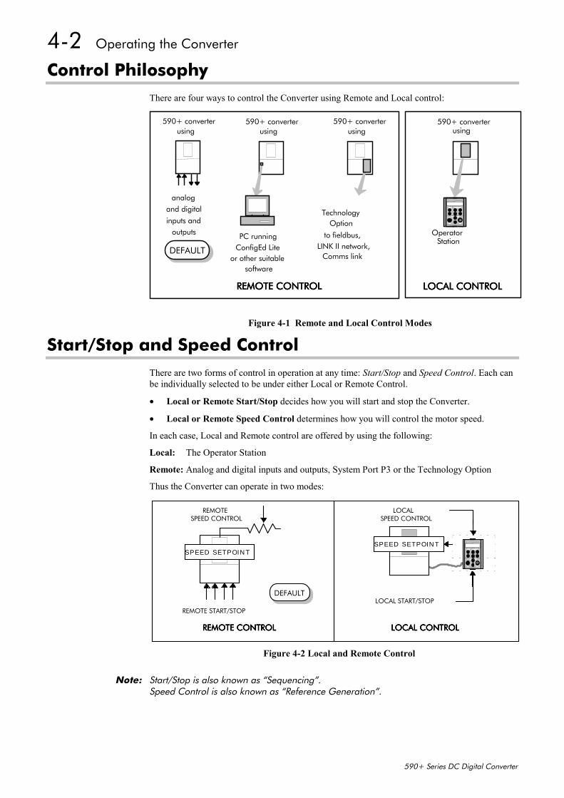
4-2 Operating the Converter
590+ Series DC Digital Converter
Control PhilosophyThere are four ways to control the Converter using Remote and Local control:
Start/Stop and Speed ControlThere are two forms of control in operation at any time: Start/Stop and Speed Control. Each canbe individually selected to be under either Local or Remote Control.
• Local or Remote Start/Stop decides how you will start and stop the Converter.
• Local or Remote Speed Control determines how you will control the motor speed.
In each case, Local and Remote control are offered by using the following:
Local: The Operator Station
Remote: Analog and digital inputs and outputs, System Port P3 or the Technology Option
Thus the Converter can operate in two modes:
Note: Start/Stop is also known as “Sequencing”.Speed Control is also known as “Reference Generation”.
analogand digital
inputs andoutputs PC running
ConfigEd Liteor other suitable
software
Technology
REMOTE CONTROLREMOTE CONTROLREMOTE CONTROLREMOTE CONTROL
590+ converterusing
590+ converterusing
590+ converterusing
LOCAL CONTROLLOCAL CONTROLLOCAL CONTROLLOCAL CONTROL
590+ converterusing
Option
to fieldbus,LINK II network,
Comms link
OperatorStation
DEFAULT
Figure 4-1 Remote and Local Control Modes
REMOTE START/STOP
REMOTE
LOCAL START/STOP
LOCALSPEED CONTROL SPEED CONTROL
DEFAULT
SPEED SETPOINTSPEED SETPOINT
REMOTE CONTROLREMOTE CONTROLREMOTE CONTROLREMOTE CONTROL LOCAL CONTROLLOCAL CONTROLLOCAL CONTROLLOCAL CONTROL
Figure 4-2 Local and Remote Control
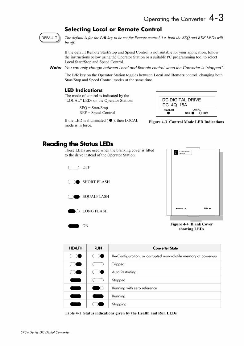
Operating the Converter 4-3
590+ Series DC Digital Converter
Selecting Local or Remote ControlThe default is for the L/R key to be set for Remote control, i.e. both the SEQ and REF LEDs willbe off.
If the default Remote Start/Stop and Speed Control is not suitable for your application, followthe instructions below using the Operator Station or a suitable PC programming tool to selectLocal Start/Stop and Speed Control.
Note: You can only change between Local and Remote control when the Converter is “stopped”.
The L/R key on the Operator Station toggles between Local and Remote control, changing bothStart/Stop and Speed Control modes at the same time.
LED IndicationsThe mode of control is indicated by the“LOCAL” LEDs on the Operator Station:
SEQ = Start/StopREF = Speed Control
If the LED is illuminated ( ), then LOCALmode is in force.
Reading the Status LEDsThese LEDs are used when the blanking cover is fittedto the drive instead of the Operator Station.
HEALTHHEALTHHEALTHHEALTH RUNRUNRUNRUN Converter StateConverter StateConverter StateConverter State
Re-Configuration, or corrupted non-volatile memory at power-up
Tripped
Auto Restarting
Stopped
Running with zero reference
Running
Stopping
Table 4-1 Status indications given by the Health and Run LEDs
DEFAULT
HEALTH LOCALSEQ REF
DC DIGITAL DRIVEDC 4Q 15A
Figure 4-3 Control Mode LED Indications
EUROTHERMDRIVES
RUNHEALTH
Figure 4-4 Blank Covershowing LEDs
OFF
SHORT FLASH
EQUALFLASH
LONG FLASH
ON
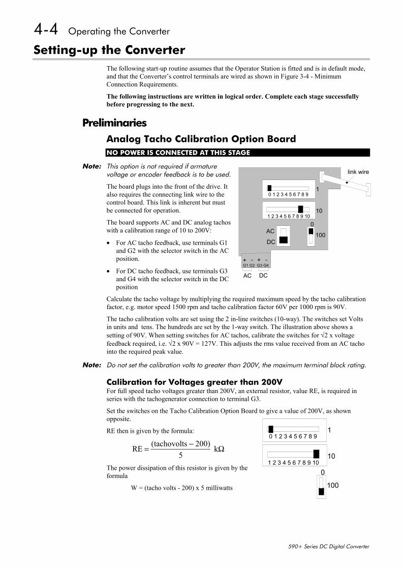
4-4 Operating the Converter
590+ Series DC Digital Converter
Setting-up the ConverterThe following start-up routine assumes that the Operator Station is fitted and is in default mode,and that the Converter’s control terminals are wired as shown in Figure 3-4 - MinimumConnection Requirements.
The following instructions are written in logical order. Complete each stage successfullybefore progressing to the next.
PreliminariesAnalog Tacho Calibration Option BoardNO POWER IS CONNECTED AT THIS STAGE
Note: This option is not required if armaturevoltage or encoder feedback is to be used.
The board plugs into the front of the drive. Italso requires the connecting link wire to thecontrol board. This link is inherent but mustbe connected for operation.
The board supports AC and DC analog tachoswith a calibration range of 10 to 200V:
• For AC tacho feedback, use terminals G1and G2 with the selector switch in the ACposition.
• For DC tacho feedback, use terminals G3and G4 with the selector switch in the DCposition
Calculate the tacho voltage by multiplying the required maximum speed by the tacho calibrationfactor, e.g. motor speed 1500 rpm and tacho calibration factor 60V per 1000 rpm is 90V.
The tacho calibration volts are set using the 2 in-line switches (10-way). The switches set Voltsin units and tens. The hundreds are set by the 1-way switch. The illustration above shows asetting of 90V. When setting switches for AC tachos, calibrate the switches for √2 x voltagefeedback required, i.e. √2 x 90V = 127V. This adjusts the rms value received from an AC tachointo the required peak value.
Note: Do not set the calibration volts to greater than 200V, the maximum terminal block rating.
Calibration for Voltages greater than 200VFor full speed tacho voltages greater than 200V, an external resistor, value RE, is required inseries with the tachogenerator connection to terminal G3.
Set the switches on the Tacho Calibration Option Board to give a value of 200V, as shownopposite.
RE then is given by the formula:
RE (tachovolts 200)5
k= − Ω
The power dissipation of this resistor is given by theformula
W = (tacho volts - 200) x 5 milliwatts
1
10
0
100AC
DC
G1 G2 G3 G4
AC DC
link wire
1 2 3 4 5 6 7 8 9 10
0 1 2 3 4 5 6 7 8 9
+ +- -
1
10
0
100
1 2 3 4 5 6 7 8 9 10
0 1 2 3 4 5 6 7 8 9
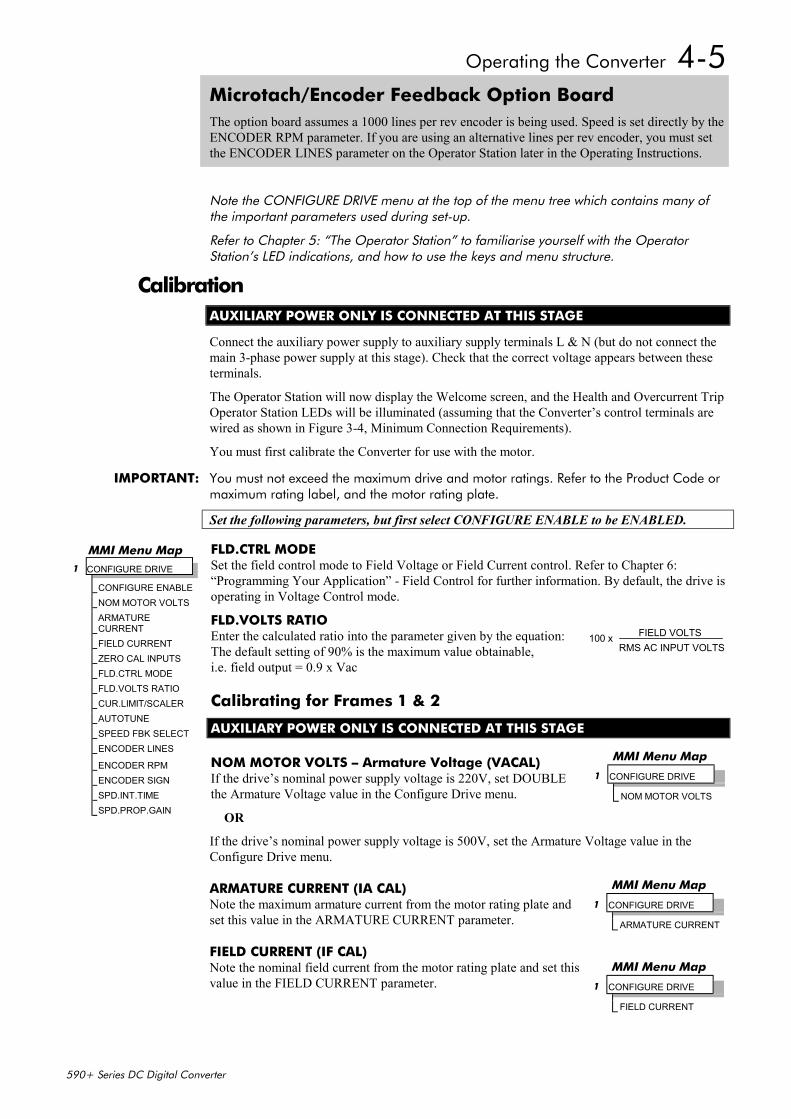
Operating the Converter 4-5
590+ Series DC Digital Converter
Microtach/Encoder Feedback Option BoardThe option board assumes a 1000 lines per rev encoder is being used. Speed is set directly by theENCODER RPM parameter. If you are using an alternative lines per rev encoder, you must setthe ENCODER LINES parameter on the Operator Station later in the Operating Instructions.
Note the CONFIGURE DRIVE menu at the top of the menu tree which contains many ofthe important parameters used during set-up.
Refer to Chapter 5: “The Operator Station” to familiarise yourself with the OperatorStation’s LED indications, and how to use the keys and menu structure.
CalibrationAUXILIARY POWER ONLY IS CONNECTED AT THIS STAGE
Connect the auxiliary power supply to auxiliary supply terminals L & N (but do not connect themain 3-phase power supply at this stage). Check that the correct voltage appears between theseterminals.
The Operator Station will now display the Welcome screen, and the Health and Overcurrent TripOperator Station LEDs will be illuminated (assuming that the Converter’s control terminals arewired as shown in Figure 3-4, Minimum Connection Requirements).
You must first calibrate the Converter for use with the motor.
IMPORTANT: You must not exceed the maximum drive and motor ratings. Refer to the Product Code ormaximum rating label, and the motor rating plate.
Set the following parameters, but first select CONFIGURE ENABLE to be ENABLED.
FLD.CTRL MODESet the field control mode to Field Voltage or Field Current control. Refer to Chapter 6:“Programming Your Application” - Field Control for further information. By default, the drive isoperating in Voltage Control mode.
FLD.VOLTS RATIOEnter the calculated ratio into the parameter given by the equation:The default setting of 90% is the maximum value obtainable,i.e. field output = 0.9 x Vac
Calibrating for Frames 1 & 2
AUXILIARY POWER ONLY IS CONNECTED AT THIS STAGE
NOM MOTOR VOLTS – Armature Voltage (VACAL)If the drive’s nominal power supply voltage is 220V, set DOUBLEthe Armature Voltage value in the Configure Drive menu.
OR
If the drive’s nominal power supply voltage is 500V, set the Armature Voltage value in theConfigure Drive menu.
ARMATURE CURRENT (IA CAL)Note the maximum armature current from the motor rating plate andset this value in the ARMATURE CURRENT parameter.
FIELD CURRENT (IF CAL)Note the nominal field current from the motor rating plate and set thisvalue in the FIELD CURRENT parameter.
MMI Menu Map1 CONFIGURE DRIVE
CONFIGURE ENABLENOM MOTOR VOLTSARMATURECURRENTFIELD CURRENTZERO CAL INPUTSFLD.CTRL MODEFLD.VOLTS RATIOCUR.LIMIT/SCALERAUTOTUNESPEED FBK SELECTENCODER LINES
ENCODER RPMENCODER SIGNSPD.INT.TIMESPD.PROP.GAIN
FIELD VOLTSRMS AC INPUT VOLTS
100 x
MMI Menu Map
1 CONFIGURE DRIVE
NOM MOTOR VOLTS
MMI Menu Map
1 CONFIGURE DRIVE
ARMATURE CURRENT
MMI Menu Map
1 CONFIGURE DRIVE
FIELD CURRENT
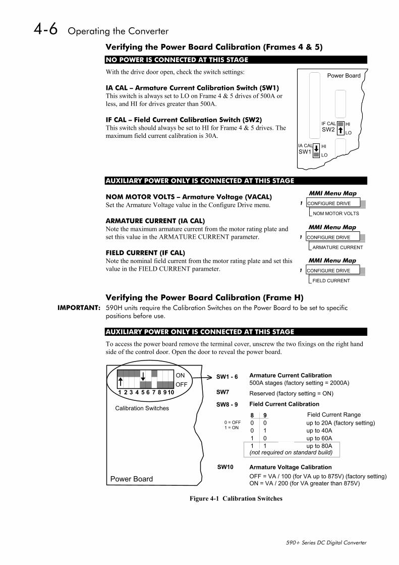
4-6 Operating the Converter
590+ Series DC Digital Converter
Verifying the Power Board Calibration (Frames 4 & 5)
NO POWER IS CONNECTED AT THIS STAGE
With the drive door open, check the switch settings:
IA CAL – Armature Current Calibration Switch (SW1)This switch is always set to LO on Frame 4 & 5 drives of 500A orless, and HI for drives greater than 500A.
IF CAL – Field Current Calibration Switch (SW2)This switch should always be set to HI for Frame 4 & 5 drives. Themaximum field current calibration is 30A.
AUXILIARY POWER ONLY IS CONNECTED AT THIS STAGE
NOM MOTOR VOLTS – Armature Voltage (VACAL)Set the Armature Voltage value in the Configure Drive menu.
ARMATURE CURRENT (IA CAL)Note the maximum armature current from the motor rating plate andset this value in the ARMATURE CURRENT parameter.
FIELD CURRENT (IF CAL)Note the nominal field current from the motor rating plate and set thisvalue in the FIELD CURRENT parameter.
Verifying the Power Board Calibration (Frame H)IMPORTANT: 590H units require the Calibration Switches on the Power Board to be set to specific
positions before use.
AUXILIARY POWER ONLY IS CONNECTED AT THIS STAGE
To access the power board remove the terminal cover, unscrew the two fixings on the right handside of the control door. Open the door to reveal the power board.
Power Board
Calibration Switches
ONOFF
9
SW7
SW8 - 9
1 = ON0 = OFF
SW10
SW1 - 6 Armature Current Calibration500A stages (factory setting = 2000A)
Reserved (factory setting = ON)
80 0 x 1 up to 20A (factory setting)0 1 x 2 up to 40A1 0 x 3 up to 60A1 1 x 4 up to 80A
OFF = VA / 100 (for VA up to 875V) (factory setting)ON = VA / 200 (for VA greater than 875V)
Field Current CalibrationMultiplier Field Current Range
Armature Voltage Calibration
(not required on standard build)
1 2 3 4 5 6 8 9 107
Figure 4-1 Calibration Switches
MMI Menu Map
1 CONFIGURE DRIVE
NOM MOTOR VOLTS
MMI Menu Map
1 CONFIGURE DRIVE
ARMATURE CURRENT
MMI Menu Map
1 CONFIGURE DRIVE
FIELD CURRENT
Power Board
SW2
SW1
HI
LO
HI
LO
IF CAL
IA CAL
Operating the Converter 4-7
590+ Series DC Digital Converter
Field Current (IF CAL)1. Set the Field Current calibration switches 8 and 9 to give the required Field Current range.
The drive’s Product Code includes the value for Field Current. If you change the FieldCurrent from the 20A factory setting to another value, you must now select the correctProduct Code rating:
Note the current Product Code which is displayed on the MMI’s Welcome screen at thetop of the menu, e.g. DC 4Q 1700A 20 D (20 = 20A Field Current range)
Now, for instance, if you have set the Field Current range to be 40A, you must select theappropriate Product Code for a Field Current range of 40A, e.g. DC 4Q 1700A 40 D
To do this, refer to Chapter 5: “The Operator Station” – Changing the Stack Size (3-button reset).
2. Note the nominal field current from the motor rating plate and setthis value in the FIELD CURRENT parameter.
Armature Current (IA CAL)1. Check that calibration switches 1 to 4 are in the “ON” position,
and 5 to 6 are in the “OFF” position. Setting is for 2000A.
2. Note the maximum armature current from the motor rating plateand set this value in the ARMATURE CURRENT parameter.
Armature VoltageIf the required Armature Voltage is 525V or less, set SW10 to OFF.
Set the Nominal Motor Voltage value in the Configure Drive menu.
OR
If the required Armature Voltage is greater than 525V, set SW10 to ON.
Set HALF the Nominal Motor Voltage value in the Configure Drive menu.
Now select CONFIGURE ENABLE to be DISABLED and perform a PARAMETER SAVE.
Selecting Speed FeedbackAUXILIARY POWER ONLY IS CONNECTED AT THIS STAGE
Use a digital voltmeter to check for the following: (relative to terminal B1)
+24V rail at terminal C9, +10V rail at terminal B3, -10V rail at terminal B4
Using the Operator Station, select the correct speed feedback option.The default is ARM VOLTS FBK.
The selections are ARM VOLTS FBK, ANALOG TACH, ENCODERand ENCODER/ANALOG.
Note: Refer to Chapter 13: “Standard and Optional Equipment” - Speed Feedback OptionBoards for further information.
MMI Menu Map
1 CONFIGURE DRIVE
FIELD CURRENT
MMI Menu Map
1 CONFIGURE DRIVE
ARMATURE CURRENT
MMI Menu Map
1 CONFIGURE DRIVE
NOM MOTOR VOLTS
MMI Menu Map
1 CONFIGURE DRIVE
SPEED FBK SELECT
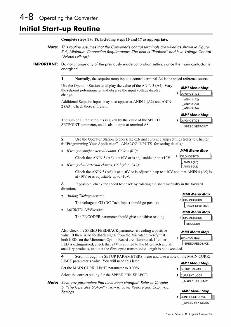
4-8 Operating the Converter
590+ Series DC Digital Converter
Initial Start-up RoutineComplete steps 1 to 18, including steps 16 and 17 as appropriate.
Note: This routine assumes that the Converter’s control terminals are wired as shown in Figure3-9, Minimum Connection Requirements. The field is “Enabled” and is in Voltage Control(default settings).
IMPORTANT: Do not change any of the previously made calibration settings once the main contactor isenergised.
1 Normally, the setpoint ramp input at control terminal A4 is the speed reference source.
Use the Operator Station to display the value of the ANIN 3 (A4). Varythe setpoint potentiometer and observe the input voltage displaychange.
Additional Setpoint Inputs may also appear at ANIN 1 (A2) and ANIN2 (A3). Check these if present.
The sum of all the setpoints is given by the value of the SPEEDSETPOINT parameter, and is also output at terminal A8.
2 Use the Operator Station to check the external current clamp settings (refer to Chapter6: “Programming Your Application” - ANALOG INPUTS for setting details):
• If using a single external clamp, C6 low (0V):
Check that ANIN 5 (A6) is +10V or is adjustable up to +10V.
• If using dual external clamps, C6 high (+24V):
Check the ANIN 5 (A6) is at +10V or is adjustable up to +10V and that ANIN 4 (A5) isat -10V or is adjustable up to -10V.
3 If possible, check the speed feedback by rotating the shaft manually in the forwarddirection.
• Analog Tachogenerator:
The voltage at G3 (DC Tach Input) should go positive.
• MICROTACH/Encoder
The ENCODER parameter should give a positive reading.
Also check the SPEED FEEDBACK parameter is reading a positivevalue. If there is no feedback signal from the Microtach, verify thatboth LEDs on the Microtach Option Board are illuminated. If eitherLED is extinguished, check that 24V is applied to the Microtach and allancillary products, and that the fibre optic transmission length is not exceeded.
4 Scroll through the SETUP PARAMETERS menu and take a note of the MAIN CURR.LIMIT parameter’s value. You will need this later.
Set the MAIN CURR. LIMIT parameter to 0.00%.
Select the correct setting for the SPEED FBK SELECT.
Note: Save any parameters that have been changed. Refer to Chapter5: “The Operator Station” - How to Save, Restore and Copy yourSettings.
MMI Menu Map
1 DIAGNOSTICS
ANIN 1 (A2)ANIN 2 (A3)ANIN 3 (A4)
MMI Menu Map
1 DIAGNOSTICS
SPEED SETPOINT
MMI Menu Map
1 DIAGNOSTICS
ANIN 4 (A5)ANIN 5 (A6)
MMI Menu Map 1 DIAGNOSTICS TACH INPUT (B2)
MMI Menu Map 1 DIAGNOSTICS ENCODER
MMI Menu Map
1 DIAGNOSTICS
SPEED FEEDBACK
MMI Menu Map
1 SETUP PARAMETERS
2 CURRENT LOOP
MAIN CURR. LIMIT
MMI Menu Map
1 CONFIGURE DRIVE
SPEED FBK SELECT
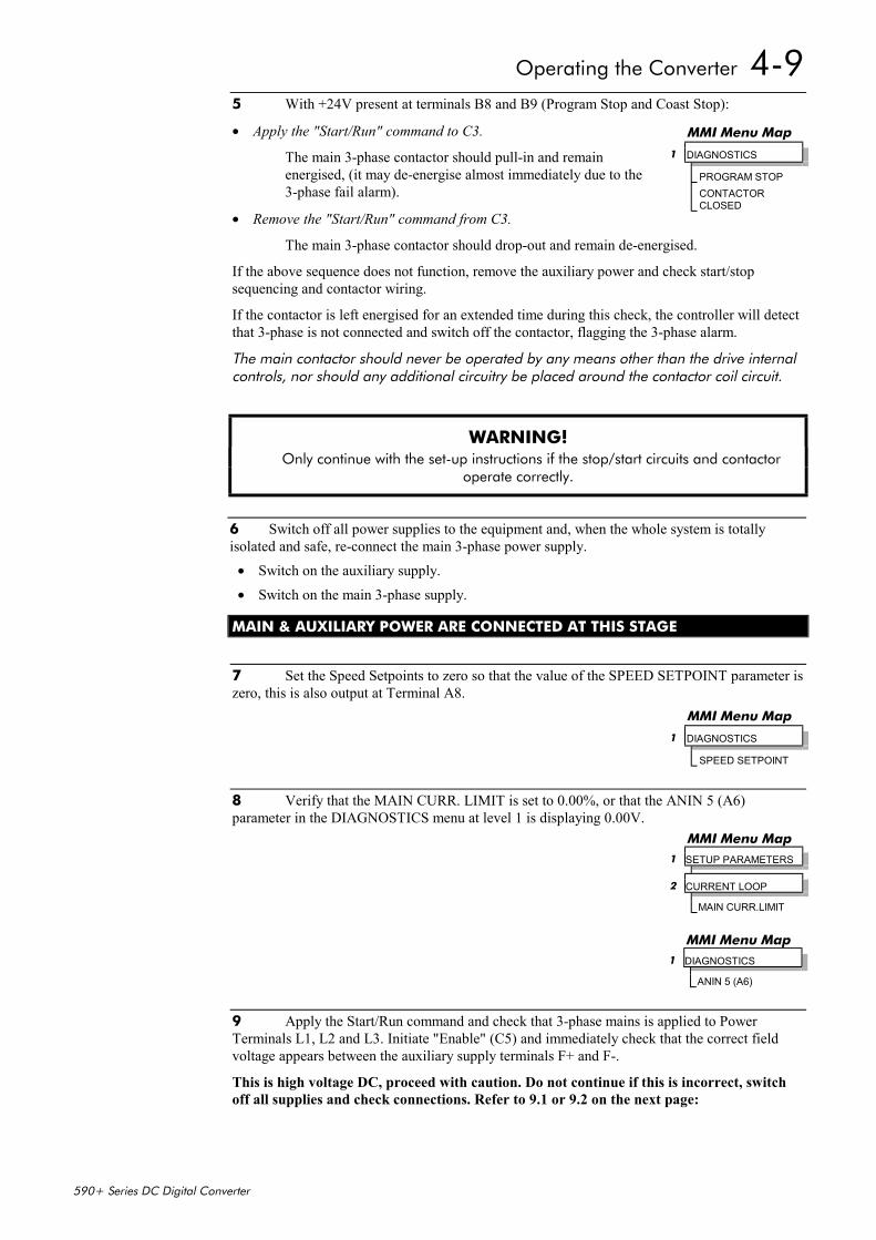
Operating the Converter 4-9
590+ Series DC Digital Converter
5 With +24V present at terminals B8 and B9 (Program Stop and Coast Stop):
• Apply the "Start/Run" command to C3.
The main 3-phase contactor should pull-in and remainenergised, (it may de-energise almost immediately due to the3-phase fail alarm).
• Remove the "Start/Run" command from C3.
The main 3-phase contactor should drop-out and remain de-energised.
If the above sequence does not function, remove the auxiliary power and check start/stopsequencing and contactor wiring.
If the contactor is left energised for an extended time during this check, the controller will detectthat 3-phase is not connected and switch off the contactor, flagging the 3-phase alarm.
The main contactor should never be operated by any means other than the drive internalcontrols, nor should any additional circuitry be placed around the contactor coil circuit.
WARNING! Only continue with the set-up instructions if the stop/start circuits and contactor
operate correctly.
6 Switch off all power supplies to the equipment and, when the whole system is totallyisolated and safe, re-connect the main 3-phase power supply.
• Switch on the auxiliary supply.
• Switch on the main 3-phase supply.
MAIN & AUXILIARY POWER ARE CONNECTED AT THIS STAGE
7 Set the Speed Setpoints to zero so that the value of the SPEED SETPOINT parameter iszero, this is also output at Terminal A8.
8 Verify that the MAIN CURR. LIMIT is set to 0.00%, or that the ANIN 5 (A6)parameter in the DIAGNOSTICS menu at level 1 is displaying 0.00V.
9 Apply the Start/Run command and check that 3-phase mains is applied to PowerTerminals L1, L2 and L3. Initiate "Enable" (C5) and immediately check that the correct fieldvoltage appears between the auxiliary supply terminals F+ and F-.
This is high voltage DC, proceed with caution. Do not continue if this is incorrect, switchoff all supplies and check connections. Refer to 9.1 or 9.2 on the next page:
MMI Menu Map 1 DIAGNOSTICS PROGRAM STOP CONTACTOR
CLOSED
MMI Menu Map 1 DIAGNOSTICS SPEED SETPOINT
MMI Menu Map 1 SETUP PARAMETERS 2 CURRENT LOOP MAIN CURR.LIMIT
MMI Menu Map 1 DIAGNOSTICS ANIN 5 (A6)
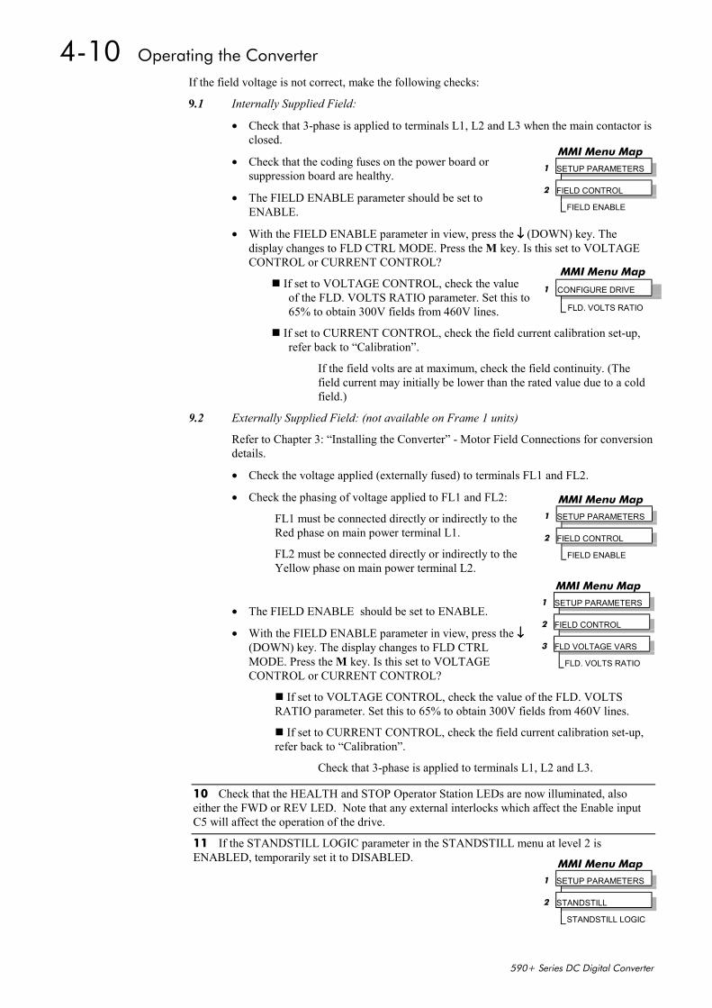
4-10 Operating the Converter
590+ Series DC Digital Converter
If the field voltage is not correct, make the following checks:
9.1 Internally Supplied Field:
• Check that 3-phase is applied to terminals L1, L2 and L3 when the main contactor isclosed.
• Check that the coding fuses on the power board orsuppression board are healthy.
• The FIELD ENABLE parameter should be set toENABLE.
• With the FIELD ENABLE parameter in view, press the ↓↓↓↓ (DOWN) key. Thedisplay changes to FLD CTRL MODE. Press the M key. Is this set to VOLTAGECONTROL or CURRENT CONTROL?
If set to VOLTAGE CONTROL, check the valueof the FLD. VOLTS RATIO parameter. Set this to65% to obtain 300V fields from 460V lines.
If set to CURRENT CONTROL, check the field current calibration set-up,refer back to “Calibration”.
If the field volts are at maximum, check the field continuity. (Thefield current may initially be lower than the rated value due to a coldfield.)
9.2 Externally Supplied Field: (not available on Frame 1 units)
Refer to Chapter 3: “Installing the Converter” - Motor Field Connections for conversiondetails.
• Check the voltage applied (externally fused) to terminals FL1 and FL2.
• Check the phasing of voltage applied to FL1 and FL2:
FL1 must be connected directly or indirectly to theRed phase on main power terminal L1.
FL2 must be connected directly or indirectly to theYellow phase on main power terminal L2.
• The FIELD ENABLE should be set to ENABLE.
• With the FIELD ENABLE parameter in view, press the ↓↓↓↓(DOWN) key. The display changes to FLD CTRLMODE. Press the M key. Is this set to VOLTAGECONTROL or CURRENT CONTROL?
If set to VOLTAGE CONTROL, check the value of the FLD. VOLTSRATIO parameter. Set this to 65% to obtain 300V fields from 460V lines.
If set to CURRENT CONTROL, check the field current calibration set-up,refer back to “Calibration”.
Check that 3-phase is applied to terminals L1, L2 and L3.
10 Check that the HEALTH and STOP Operator Station LEDs are now illuminated, alsoeither the FWD or REV LED. Note that any external interlocks which affect the Enable inputC5 will affect the operation of the drive.
11 If the STANDSTILL LOGIC parameter in the STANDSTILL menu at level 2 isENABLED, temporarily set it to DISABLED.
MMI Menu Map1 SETUP PARAMETERS
2 FIELD CONTROL
FIELD ENABLE
MMI Menu Map
1 CONFIGURE DRIVE
FLD. VOLTS RATIO
MMI Menu Map 1 SETUP PARAMETERS 2 FIELD CONTROL FIELD ENABLE
MMI Menu Map 1 SETUP PARAMETERS 2 FIELD CONTROL 3 FLD VOLTAGE VARS FLD. VOLTS RATIO
MMI Menu Map1 SETUP PARAMETERS
2 STANDSTILL
STANDSTILL LOGIC
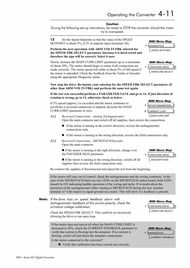
Operating the Converter 4-11
590+ Series DC Digital Converter
Caution During the following set-up instructions, be ready to STOP the converter should the motor
try to overspeed.
12 Set the Speed Setpoints so that the value of the SPEEDSETPOINT is about 5%, 0.5V at setpoint input (terminal A8).
Perform the next operation with ARM VOLTS FBK selected forthe SPEED FBK SELECT parameter (because it is hard-wired andtherefore the sign will be correct). Select it now.
Slowly increase the MAIN CURR.LIMIT parameter up to a maximumof about 20%. The motor should begin to rotate if all connections aremade correctly. The motor speed will settle at about 5% of full speed ifthe motor is unloaded. Check the feedback from the Tacho or Encoderusing the appropriate Diagnostic menu.
Now stop the drive. Re-instate your selection for the SPEED FBK SELECT parameter (ifother than ARM VOLTS FBK) and perform the same test again.
If the test was successful perform a PARAMETER SAVE and go to 14. If just direction ofrotation is wrong, go to 13, otherwise check as below.
If 5% speed (approx.) is exceeded and the motor continues toaccelerate a reversed connection is implied, decrease the MAINCURR.LIMIT parameter to zero.
12.1 Reversed Connections - Analog Tachogenerator:Open the main contactor and switch off all supplies, then correct the connections.
If the motor is turning in the correct direction, reverse the tachogeneratorconnections only.
If the motor is turning in the wrong direction, reverse the field connections only.
12.2 Reversed Connections - MICROTACH/Encoder:Open the main contactor.
If the motor is turning in the right direction, change overthe ENCODER SIGN parameter.
If the motor is turning in the wrong direction, switch off allsupplies then reverse the field connections only.
Re-connect the supplies if disconnected and repeat the test from the beginning.
If the motor still runs out of control, check the tachogenerator and the wiring continuity. In thecase of the MICROTACH there are two LED's on the MICROTACH option board, both LED'sshould be ON indicating healthy operation of the wiring and tacho. If in doubt about theoperation of the tachogenerator either Analog or MICROTACH during this test, monitorterminal A7 with respect to signal ground on a meter. This will show if a feedback is present.
Note: If the drive trips on speed feedback alarm withtachogenerator feedback of the correct polarity, check thearmature voltage calibration.
Check the SPEED FBK SELECT. This could be set incorrectlyallowing the drive to run open loop.
If the motor does not turn at all when the MAIN CURR.LIMIT isincreased to 20%, check the CURRENT FEEDBACK parameter toverify that current is flowing into the armature. If no current isflowing, switch off and check the armature connections.Is the motor connected to the converter?
Verify that calibration has been carried out correctly.
MMI Menu Map1 DIAGNOSTICS
SPEED SETPOINT
MMI Menu Map
1 CONFIGURE DRIVE
SPEED FBK SELECT
MMI Menu Map1 SETUP PARAMETERS
2 CURRENT LOOP
MAIN CURR.LIMIT
MMI Menu Map
1 CONFIGURE DRIVE
ENCODER SIGN
MMI Menu Map
1 CONFIGURE DRIVE
SPEED FBK SELECT
MMI Menu Map1 DIAGNOSTICS
CURRENT FEEDBACK
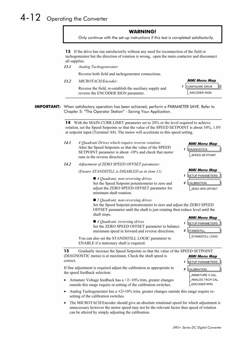
4-12 Operating the Converter
590+ Series DC Digital Converter
WARNING! Only continue with the set-up instructions if this test is completed satisfactorily.
13 If the drive has run satisfactorily without any need for reconnection of the field ortachogenerator but the direction of rotation is wrong, open the main contactor and disconnectall supplies.
13.1 Analog Tachogenerator:
Reverse both field and tachogenerator connections.
13.2 MICROTACH/Encoder:
Reverse the field, re-establish the auxiliary supply andreverse the ENCODER SIGN parameter.
IMPORTANT: When satisfactory operation has been achieved, perform a PARAMETER SAVE. Refer toChapter 5: “The Operator Station” - Saving Your Application.
14 With the MAIN CURR.LIMIT parameter set to 20% or the level required to achieverotation, set the Speed Setpoints so that the value of the SPEED SETPOINT is about 10%, 1.0Vat setpoint input (Terminal A8). The motor will accelerate to this speed setting.
14.1 4 Quadrant Drives which require reverse rotation:Alter the Speed Setpoints so that the value of the SPEEDSETPOINT parameter is about -10% and check that motorruns in the reverse direction.
14.2 Adjustment of ZERO SPEED OFFSET parameter:
(Ensure STANDSTILL is DISABLED as in item 11)
4 Quadrant, non-reversing drivesSet the Speed Setpoint potentiometer to zero andadjust the ZERO SPEED OFFSET parameter forminimum shaft rotation.
2 Quadrant, non-reversing drivesSet the Speed Setpoint potentiometer to zero and adjust the ZERO SPEEDOFFSET parameter until the shaft is just rotating then reduce level until theshaft stops.
4 Quadrant, reversing drivesSet the ZERO SPEED OFFSET parameter to balancemaximum speed in forward and reverse directions.
You can also set the STANDSTILL LOGIC parameter toENABLE if a stationary shaft is required.
15 Gradually increase the Speed Setpoints so that the value of the SPEED SETPOINT(DIAGNOSTIC menu) is at maximum. Check the shaft speed iscorrect.
If fine adjustment is required adjust the calibration as appropriate tothe speed feedback selection:
• Armature Voltage feedback has a +2/-10% trim, greater changesoutside this range require re-setting of the calibration switches.
• Analog Tachogenerator has a +2/-10% trim, greater changes outside this range require re-setting of the calibration switches.
• The MICROTACH/Encoder should give an absolute rotational speed for which adjustment isunnecessary however the motor speed may not be the relevant factor thus speed of rotationcan be altered by simply adjusting the calibration.
MMI Menu Map
1 CONFIGURE DRIVE
ENCODER SIGN
MMI Menu Map1 DIAGNOSTICS
SPEED SETPOINT
MMI Menu Map1 SETUP PARAMETERS
2 CALIBRATION
ZERO SPD.OFFSET
MMI Menu Map1 SETUP PARAMETERS
2 STANDSTILL
STANDSTILL LOGIC
MMI Menu Map1 SETUP PARAMETERS
2 CALIBRATION
ARMATURE V CAL.ANALOG TACH CAL.ENCODER RPM
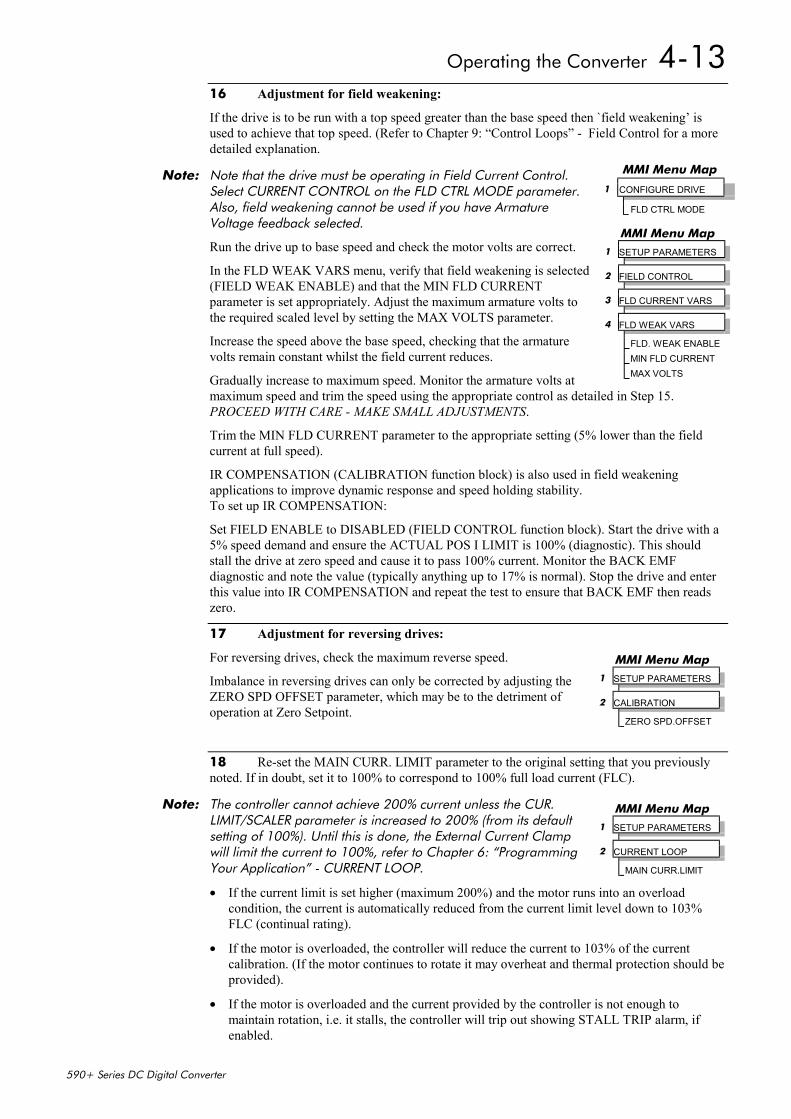
Operating the Converter 4-13
590+ Series DC Digital Converter
16 Adjustment for field weakening:
If the drive is to be run with a top speed greater than the base speed then `field weakening’ isused to achieve that top speed. (Refer to Chapter 9: “Control Loops” - Field Control for a moredetailed explanation.
Note: Note that the drive must be operating in Field Current Control.Select CURRENT CONTROL on the FLD CTRL MODE parameter.Also, field weakening cannot be used if you have ArmatureVoltage feedback selected.
Run the drive up to base speed and check the motor volts are correct.
In the FLD WEAK VARS menu, verify that field weakening is selected(FIELD WEAK ENABLE) and that the MIN FLD CURRENTparameter is set appropriately. Adjust the maximum armature volts tothe required scaled level by setting the MAX VOLTS parameter.
Increase the speed above the base speed, checking that the armaturevolts remain constant whilst the field current reduces.
Gradually increase to maximum speed. Monitor the armature volts atmaximum speed and trim the speed using the appropriate control as detailed in Step 15.PROCEED WITH CARE - MAKE SMALL ADJUSTMENTS.
Trim the MIN FLD CURRENT parameter to the appropriate setting (5% lower than the fieldcurrent at full speed).
IR COMPENSATION (CALIBRATION function block) is also used in field weakeningapplications to improve dynamic response and speed holding stability.To set up IR COMPENSATION:
Set FIELD ENABLE to DISABLED (FIELD CONTROL function block). Start the drive with a5% speed demand and ensure the ACTUAL POS I LIMIT is 100% (diagnostic). This shouldstall the drive at zero speed and cause it to pass 100% current. Monitor the BACK EMFdiagnostic and note the value (typically anything up to 17% is normal). Stop the drive and enterthis value into IR COMPENSATION and repeat the test to ensure that BACK EMF then readszero.
17 Adjustment for reversing drives:
For reversing drives, check the maximum reverse speed.
Imbalance in reversing drives can only be corrected by adjusting theZERO SPD OFFSET parameter, which may be to the detriment ofoperation at Zero Setpoint.
18 Re-set the MAIN CURR. LIMIT parameter to the original setting that you previouslynoted. If in doubt, set it to 100% to correspond to 100% full load current (FLC).
Note: The controller cannot achieve 200% current unless the CUR.LIMIT/SCALER parameter is increased to 200% (from its defaultsetting of 100%). Until this is done, the External Current Clampwill limit the current to 100%, refer to Chapter 6: “ProgrammingYour Application” - CURRENT LOOP.
• If the current limit is set higher (maximum 200%) and the motor runs into an overloadcondition, the current is automatically reduced from the current limit level down to 103%FLC (continual rating).
• If the motor is overloaded, the controller will reduce the current to 103% of the currentcalibration. (If the motor continues to rotate it may overheat and thermal protection should beprovided).
• If the motor is overloaded and the current provided by the controller is not enough tomaintain rotation, i.e. it stalls, the controller will trip out showing STALL TRIP alarm, ifenabled.
MMI Menu Map
1 CONFIGURE DRIVE
FLD CTRL MODE
MMI Menu Map 1 SETUP PARAMETERS 2 FIELD CONTROL 3 FLD CURRENT VARS 4 FLD WEAK VARS FLD. WEAK ENABLE MIN FLD CURRENT MAX VOLTS
MMI Menu Map 1 SETUP PARAMETERS 2 CALIBRATION ZERO SPD.OFFSET
MMI Menu Map 1 SETUP PARAMETERS 2 CURRENT LOOP MAIN CURR.LIMIT
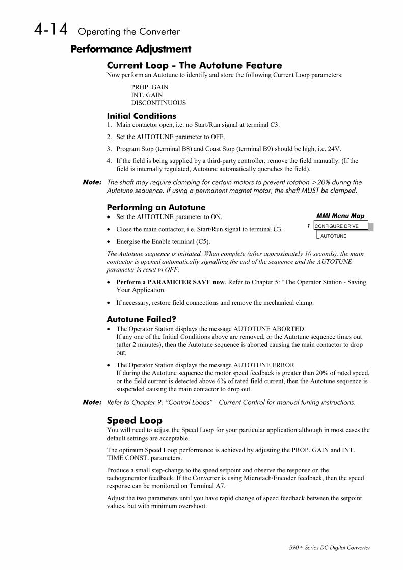
4-14 Operating the Converter
590+ Series DC Digital Converter
Performance AdjustmentCurrent Loop - The Autotune FeatureNow perform an Autotune to identify and store the following Current Loop parameters:
PROP. GAININT. GAINDISCONTINUOUS
Initial Conditions1. Main contactor open, i.e. no Start/Run signal at terminal C3.
2. Set the AUTOTUNE parameter to OFF.
3. Program Stop (terminal B8) and Coast Stop (terminal B9) should be high, i.e. 24V.
4. If the field is being supplied by a third-party controller, remove the field manually. (If thefield is internally regulated, Autotune automatically quenches the field).
Note: The shaft may require clamping for certain motors to prevent rotation >20% during theAutotune sequence. If using a permanent magnet motor, the shaft MUST be clamped.
Performing an Autotune• Set the AUTOTUNE parameter to ON.
• Close the main contactor, i.e. Start/Run signal to terminal C3.
• Energise the Enable terminal (C5).
The Autotune sequence is initiated. When complete (after approximately 10 seconds), the maincontactor is opened automatically signalling the end of the sequence and the AUTOTUNEparameter is reset to OFF.
• Perform a PARAMETER SAVE now. Refer to Chapter 5: “The Operator Station - SavingYour Application.
• If necessary, restore field connections and remove the mechanical clamp.
Autotune Failed?• The Operator Station displays the message AUTOTUNE ABORTED
If any one of the Initial Conditions above are removed, or the Autotune sequence times out(after 2 minutes), then the Autotune sequence is aborted causing the main contactor to dropout.
• The Operator Station displays the message AUTOTUNE ERRORIf during the Autotune sequence the motor speed feedback is greater than 20% of rated speed,or the field current is detected above 6% of rated field current, then the Autotune sequence issuspended causing the main contactor to drop out.
Note: Refer to Chapter 9: “Control Loops” - Current Control for manual tuning instructions.
Speed LoopYou will need to adjust the Speed Loop for your particular application although in most cases thedefault settings are acceptable.
The optimum Speed Loop performance is achieved by adjusting the PROP. GAIN and INT.TIME CONST. parameters.
Produce a small step-change to the speed setpoint and observe the response on thetachogenerator feedback. If the Converter is using Microtach/Encoder feedback, then the speedresponse can be monitored on Terminal A7.
Adjust the two parameters until you have rapid change of speed feedback between the setpointvalues, but with minimum overshoot.
MMI Menu Map
1 CONFIGURE DRIVE
AUTOTUNE
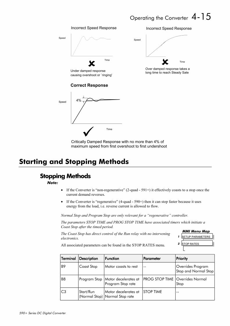
Operating the Converter 4-15
590+ Series DC Digital Converter
Starting and Stopping Methods
Stopping MethodsNote:
• If the Converter is “non-regenerative” (2-quad - 591+) it effectively coasts to a stop once thecurrent demand reverses.
• If the Converter is “regenerative” (4-quad - 590+) then it can stop faster because it usesenergy from the load, i.e. reverse current is allowed to flow.
Normal Stop and Program Stop are only relevant for a “regenerative” controller.
The parameters STOP TIME and PROG STOP TIME have associated timers which initiate aCoast Stop after the timed period.
The Coast Stop has direct control of the Run relay with no interveningelectronics.
All associated parameters can be found in the STOP RATES menu.
TerminalTerminalTerminalTerminal DescriptionDescriptionDescriptionDescription FunctionFunctionFunctionFunction ParameterParameterParameterParameter PriorityPriorityPriorityPriority
B9 Coast Stop Motor coasts to rest -- Overrides ProgramStop and Normal Stop
B8 Program Stop Motor decelerates atProgram Stop rate
PROG STOP TIME Overrides NormalStop
C3 Start/Run(Normal Stop)
Motor decelerates atNormal Stop rate
STOP TIME --
Incorrect Speed Response
Under damped response
Speed
Time
causing overshoot or `ringing'
Incorrect Speed Response
Over damped response takes along time to reach Steady Sate
Speed
Time
Correct Response
Critically Damped Response with no more than 4% ofmaximum speed from first overshoot to first undershoot
Speed
Time
4%
MMI Menu Map1 SETUP PARAMETERS
2 STOP RATES
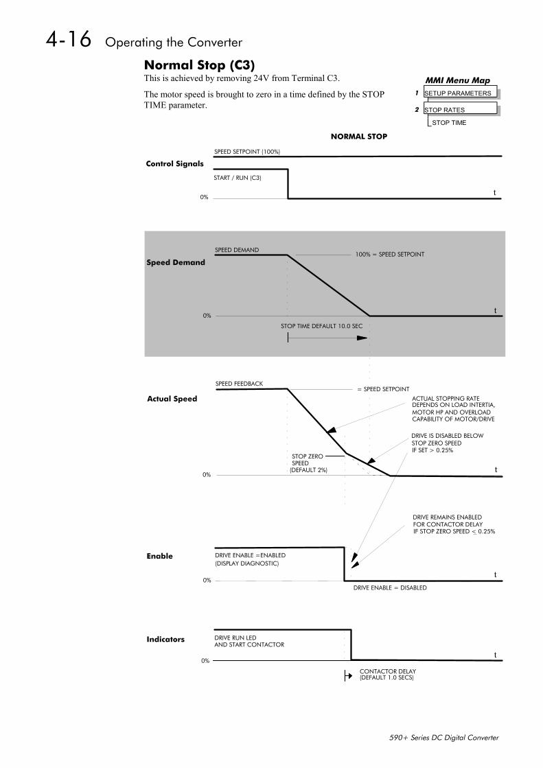
4-16 Operating the Converter
590+ Series DC Digital Converter
Normal Stop (C3)This is achieved by removing 24V from Terminal C3.
The motor speed is brought to zero in a time defined by the STOPTIME parameter.
SPEED SETPOINT (100%)
NORMAL STOP
t
START / RUN (C3)
0%
100% = SPEED SETPOINTSPEED DEMAND
STOP TIME DEFAULT 10.0 SEC
t
t
SPEED FEEDBACK= SPEED SETPOINT
STOP ZEROSPEED
(DEFAULT 2%)0%
ACTUAL STOPPING RATEDEPENDS ON LOAD INTERTIA,MOTOR HP AND OVERLOADCAPABILITY OF MOTOR/DRIVE
DRIVE IS DISABLED BELOWSTOP ZERO SPEEDIF SET > 0.25%
tDRIVE ENABLE = DISABLED
0%
DRIVE ENABLE =ENABLED(DISPLAY DIAGNOSTIC)
DRIVE REMAINS ENABLEDFOR CONTACTOR DELAYIF STOP ZERO SPEED < 0.25%
t0%
DRIVE RUN LEDAND START CONTACTOR
CONTACTOR DELAY(DEFAULT 1.0 SECS)
0%
Control Signals
Speed Demand
Actual Speed
Enable
Indicators
MMI Menu Map 1 SETUP PARAMETERS 2 STOP RATES STOP TIME
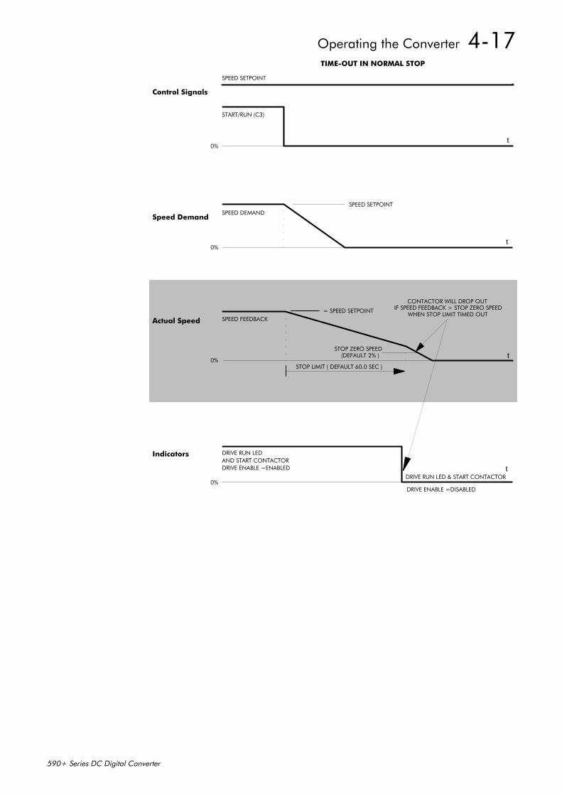
Operating the Converter 4-17
590+ Series DC Digital Converter
SPEED SETPOINT
TIME-OUT IN NORMAL STOP
0%
START/RUN (C3)
SPEED SETPOINTSPEED DEMAND
0%
0%
SPEED FEEDBACK
STOP ZERO SPEED(DEFAULT 2% )
= SPEED SETPOINT
CONTACTOR WILL DROP OUTIF SPEED FEEDBACK > STOP ZERO SPEED
WHEN STOP LIMIT TIMED OUT
0%
DRIVE ENABLE =ENABLED
DRIVE RUN LEDAND START CONTACTOR
STOP LIMIT ( DEFAULT 60.0 SEC )
DRIVE ENABLE =DISABLED
DRIVE RUN LED & START CONTACTORt
t
t
t
Control Signals
Speed Demand
Actual Speed
Indicators
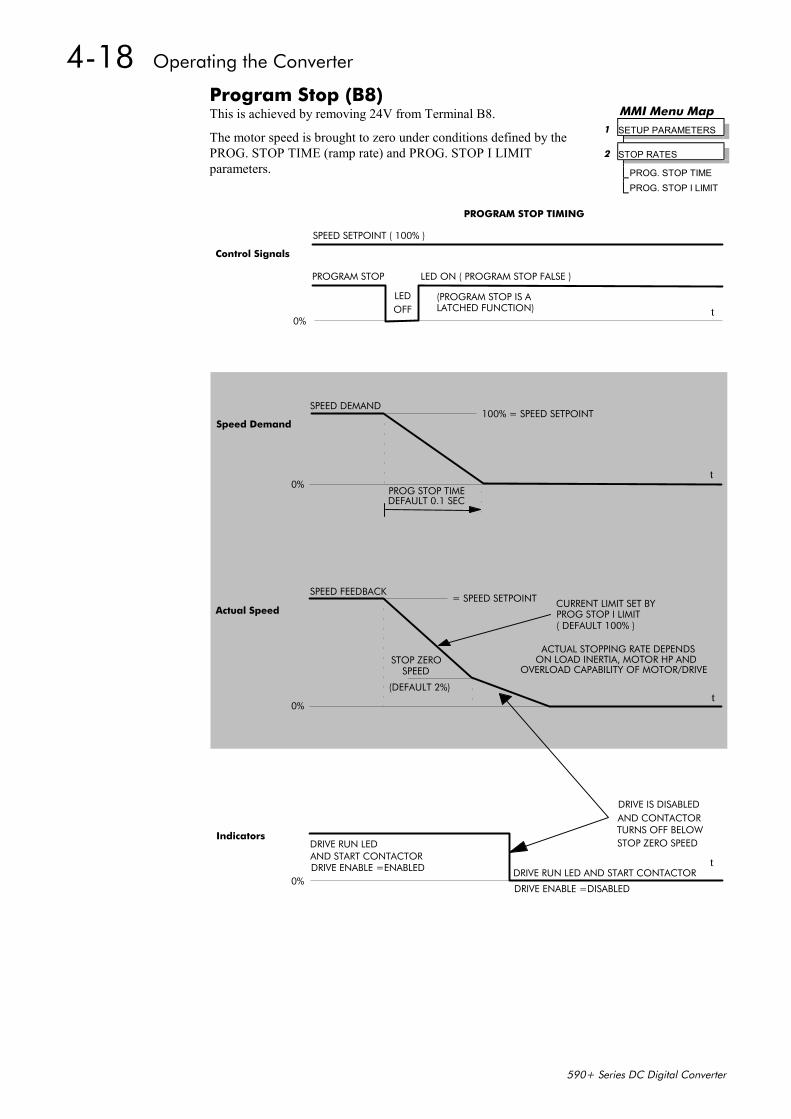
4-18 Operating the Converter
590+ Series DC Digital Converter
Program Stop (B8)This is achieved by removing 24V from Terminal B8.
The motor speed is brought to zero under conditions defined by thePROG. STOP TIME (ramp rate) and PROG. STOP I LIMITparameters.
SPEED SETPOINT ( 100% )
PROGRAM STOP TIMING
PROGRAM STOP
LEDOFF
LED ON ( PROGRAM STOP FALSE )
(PROGRAM STOP IS ALATCHED FUNCTION) t
t
100% = SPEED SETPOINT
0%
0%PROG STOP TIMEDEFAULT 0.1 SEC
SPEED DEMAND
= SPEED SETPOINT CURRENT LIMIT SET BYPROG STOP I LIMIT( DEFAULT 100% )
ACTUAL STOPPING RATE DEPENDSON LOAD INERTIA, MOTOR HP AND
OVERLOAD CAPABILITY OF MOTOR/DRIVE
t
SPEED
(DEFAULT 2%)
0%
DRIVE RUN LED
0%DRIVE ENABLE =ENABLED
DRIVE ENABLE =DISABLED
t
AND CONTACTORTURNS OFF BELOW
DRIVE RUN LED AND START CONTACTOR
STOP ZERO
SPEED FEEDBACK
DRIVE IS DISABLED
STOP ZERO SPEED
Control Signals
Speed Demand
Actual Speed
Indicators
AND START CONTACTOR
MMI Menu Map 1 SETUP PARAMETERS 2 STOP RATES PROG. STOP TIME PROG. STOP I LIMIT
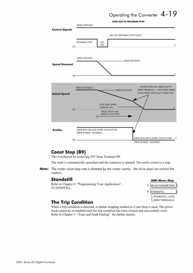
Operating the Converter 4-19
590+ Series DC Digital Converter
TIME-OUT IN PROGRAM STOP
SPEED SETPOINT
PROGRAM STOP LEDOFF
LED ON (PROGRAM STOP FALSE )
0%t
SPEED DEMANDSPEED SETPOINT
0%t
0%
SPEED FEEDBACK
STOP ZERO SPEED( DEFAULT 2% )
CONTACTOR WILL DROP OUT IFSPEED FEEDBACK > STOP ZERO SPEEDWHEN PROG STOP LIMIT TIMED OUT
t
SPEED SETPOINT
t
PROG STOP LIMIT(DEFAULT 60.0 SEC)
DRIVE RUN LED AND START CONTACTORDRIVE ENABLE =ENABLED
0%DRIVE ENABLE =DISABLED
DRIVE RUN LED & START CONTACTOR
Control Signals
Speed Demand
Actual Speed
Enable
Coast Stop (B9)This is achieved by removing 24V from Terminal B9.
The stack is automatically quenched and the contactor is opened. The motor coasts to a stop.
Note: The motor coast stop rate is dictated by the motor inertia - the drive does not control themotion.
StandstillRefer to Chapter 6: “Programming Your Application” -STANDSTILL.
The Trip ConditionWhen a trip condition is detected, a similar stopping method to Coast Stop is used. The powerstack cannot be re-enabled until the trip condition has been cleared and successfully reset.Refer to Chapter 7: “Trips and Fault Finding” for further details.
MMI Menu Map
1 SETUP PARAMETERS
2 STANDSTILL
STANDSTILL LOGICZERO THRESHOLD

4-20 Operating the Converter
590+ Series DC Digital Converter
Normal Starting MethodTo achieve a normal start of the Converter:
1. Apply 24V to Terminal C5 (Enable)
2. Apply 24V to Terminal C3 (Start)
Note: The Converter will not start if there are alarms present, or if Terminals B8 (Program Stop)or B9 (Coast Stop) are low, 0V.
Ensure that Program Stop and Coast Stop are valid before Start/Run is applied.
Advanced Starting MethodsStarting Several Converters Simultaneously1. Apply 24V to Terminal C3 (Start)
2. Use Terminal C5 (Enable) to synchronise the start-up of the Converters
Jog1. Apply 24V to Terminal C5 (Enable)
2. Apply 24V to Terminal C4 (Jog Mode)
Note: The Converter will not start if there are alarms present.
The Converter can be started using JOG SPEED 1, JOG SPEED 2 (allowing for two differentsetpoints, or perhaps to provide an Inch Forward/Inch Reverse).
Refer to Chapter 6: “Programming Your Application” - JOG/SLACK for further information.Also refer to the STOP RATES function block: the CONTACTOR DELAY parameter is used toprevent multiple operations of the main contactor from rapid use of the Jog switch.
Crawl1. Apply 24V to Terminal C3 (Start)
2. Apply 24V to Terminal C4 (Jog Mode)
Note: The Converter will not start if there are alarms present.
Start the Converter using a crawl speed, in Forward or Reverse.
Refer to Chapter 6: “Programming Your Application” - JOG/SLACK for further information.
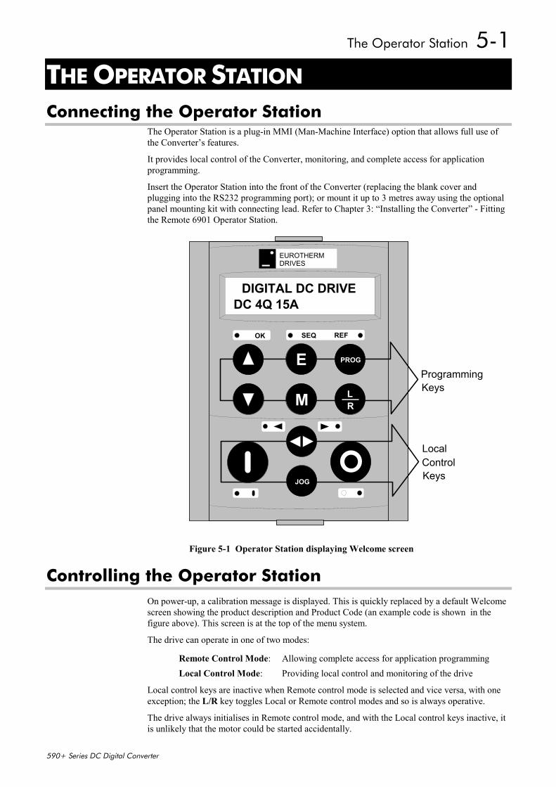
The Operator Station 5-1
590+ Series DC Digital Converter
5 THE OPERATOR STATION
Connecting the Operator StationThe Operator Station is a plug-in MMI (Man-Machine Interface) option that allows full use ofthe Converter’s features.
It provides local control of the Converter, monitoring, and complete access for applicationprogramming.
Insert the Operator Station into the front of the Converter (replacing the blank cover andplugging into the RS232 programming port); or mount it up to 3 metres away using the optionalpanel mounting kit with connecting lead. Refer to Chapter 3: “Installing the Converter” - Fittingthe Remote 6901 Operator Station.
Controlling the Operator StationOn power-up, a calibration message is displayed. This is quickly replaced by a default Welcomescreen showing the product description and Product Code (an example code is shown in thefigure above). This screen is at the top of the menu system.
The drive can operate in one of two modes:
Remote Control Mode: Allowing complete access for application programmingLocal Control Mode: Providing local control and monitoring of the drive
Local control keys are inactive when Remote control mode is selected and vice versa, with oneexception; the L/R key toggles Local or Remote control modes and so is always operative.
The drive always initialises in Remote control mode, and with the Local control keys inactive, itis unlikely that the motor could be started accidentally.
EUROTHERMDRIVES
E
M
PROG
LR
ProgrammingKeys
LocalControlKeysJOG
1DC 4Q 15ADC D I VR EI ITG ALD
OK SEQ REF
1DC 4Q 15ADIGITAL DC DRIVE
Figure 5-1 Operator Station displaying Welcome screen
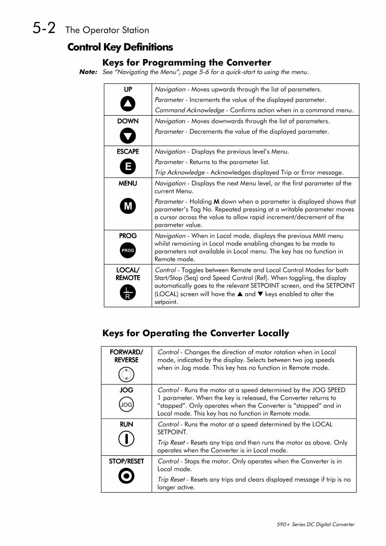
5-2 The Operator Station
590+ Series DC Digital Converter
Control Key DefinitionsKeys for Programming the Converter
Note: See “Navigating the Menu”, page 5-6 for a quick-start to using the menu.
UPUPUPUP Navigation - Moves upwards through the list of parameters.
Parameter - Increments the value of the displayed parameter.
Command Acknowledge - Confirms action when in a command menu.
DOWNDOWNDOWNDOWN Navigation - Moves downwards through the list of parameters.
Parameter - Decrements the value of the displayed parameter.
ESCAPEESCAPEESCAPEESCAPE
ENavigation - Displays the previous level’s Menu.
Parameter - Returns to the parameter list.
Trip Acknowledge - Acknowledges displayed Trip or Error message.
MENUMENUMENUMENU
M
Navigation - Displays the next Menu level, or the first parameter of thecurrent Menu.
Parameter - Holding MMMM down when a parameter is displayed shows thatparameter’s Tag No. Repeated pressing at a writable parameter movesa cursor across the value to allow rapid increment/decrement of theparameter value.
PROGPROGPROGPROG
PROG
Navigation - When in Local mode, displays the previous MMI menuwhilst remaining in Local mode enabling changes to be made toparameters not available in Local menu. The key has no function inRemote mode.
LOCAL/LOCAL/LOCAL/LOCAL/REMOTEREMOTEREMOTEREMOTE
RL
Control - Toggles between Remote and Local Control Modes for bothStart/Stop (Seq) and Speed Control (Ref). When toggling, the displayautomatically goes to the relevant SETPOINT screen, and the SETPOINT(LOCAL) screen will have the and keys enabled to alter thesetpoint.
Keys for Operating the Converter Locally
FORWARD/FORWARD/FORWARD/FORWARD/REVERSEREVERSEREVERSEREVERSE
Control - Changes the direction of motor rotation when in Localmode, indicated by the display. Selects between two jog speedswhen in Jog mode. This key has no function in Remote mode.
JOGJOGJOGJOG
JOG
Control - Runs the motor at a speed determined by the JOG SPEED1 parameter. When the key is released, the Converter returns to“stopped”. Only operates when the Converter is “stopped“ and inLocal mode. This key has no function in Remote mode.
RUNRUNRUNRUN Control - Runs the motor at a speed determined by the LOCALSETPOINT.
Trip Reset - Resets any trips and then runs the motor as above. Onlyoperates when the Converter is in Local mode.
STOPSTOPSTOPSTOP/RESET/RESET/RESET/RESET Control - Stops the motor. Only operates when the Converter is inLocal mode.
Trip Reset - Resets any trips and clears displayed message if trip is nolonger active.
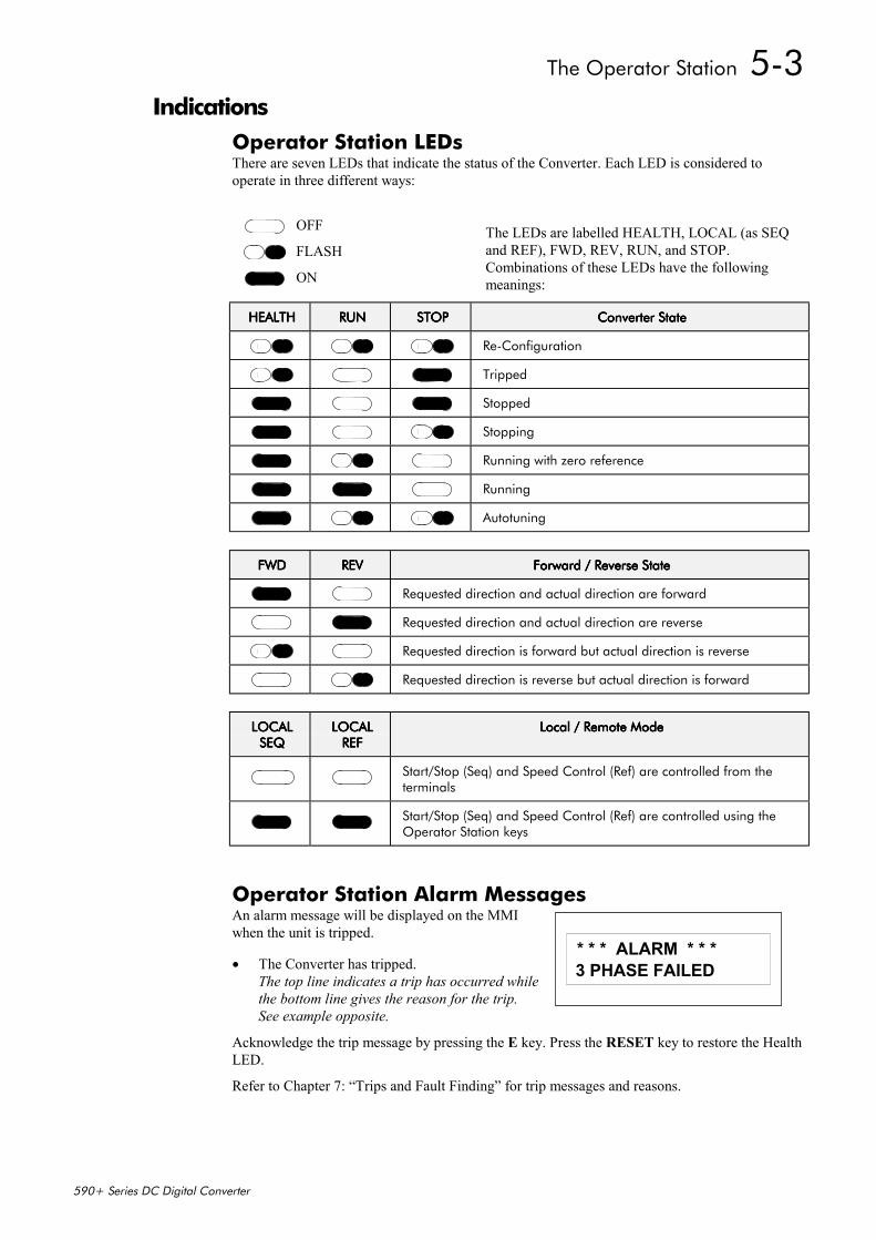
The Operator Station 5-3
590+ Series DC Digital Converter
IndicationsOperator Station LEDsThere are seven LEDs that indicate the status of the Converter. Each LED is considered tooperate in three different ways:
The LEDs are labelled HEALTH, LOCAL (as SEQand REF), FWD, REV, RUN, and STOP.Combinations of these LEDs have the followingmeanings:
HEALTHHEALTHHEALTHHEALTH RUNRUNRUNRUN STOPSTOPSTOPSTOP Converter StateConverter StateConverter StateConverter State
Re-Configuration
Tripped
Stopped
Stopping
Running with zero reference
Running
Autotuning
FWDFWDFWDFWD REVREVREVREV Forward / Reverse StateForward / Reverse StateForward / Reverse StateForward / Reverse State
Requested direction and actual direction are forward
Requested direction and actual direction are reverse
Requested direction is forward but actual direction is reverse
Requested direction is reverse but actual direction is forward
LOCALLOCALLOCALLOCALSEQSEQSEQSEQ
LOCALLOCALLOCALLOCALREFREFREFREF
Local / Remote ModeLocal / Remote ModeLocal / Remote ModeLocal / Remote Mode
Start/Stop (Seq) and Speed Control (Ref) are controlled from theterminals
Start/Stop (Seq) and Speed Control (Ref) are controlled using theOperator Station keys
Operator Station Alarm MessagesAn alarm message will be displayed on the MMIwhen the unit is tripped.
• The Converter has tripped.The top line indicates a trip has occurred whilethe bottom line gives the reason for the trip.See example opposite.
Acknowledge the trip message by pressing the E key. Press the RESET key to restore the HealthLED.
Refer to Chapter 7: “Trips and Fault Finding” for trip messages and reasons.
OFF
FLASH
ON
113 PHASE FAILED
* * * ALARM * * *
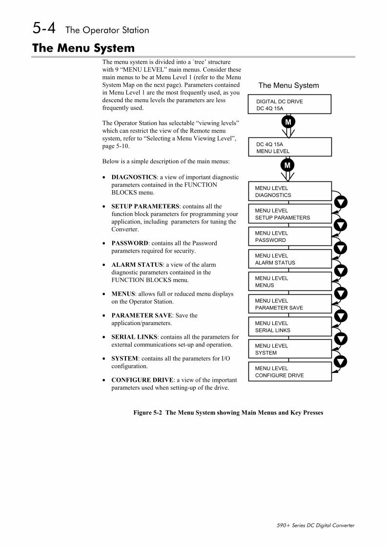
5-4 The Operator Station
590+ Series DC Digital Converter
The Menu SystemThe menu system is divided into a `tree’ structurewith 9 “MENU LEVEL” main menus. Consider thesemain menus to be at Menu Level 1 (refer to the MenuSystem Map on the next page). Parameters containedin Menu Level 1 are the most frequently used, as youdescend the menu levels the parameters are lessfrequently used.
The Operator Station has selectable “viewing levels”which can restrict the view of the Remote menusystem, refer to “Selecting a Menu Viewing Level”,page 5-10.
Below is a simple description of the main menus:
• DIAGNOSTICS: a view of important diagnosticparameters contained in the FUNCTIONBLOCKS menu.
• SETUP PARAMETERS: contains all thefunction block parameters for programming yourapplication, including parameters for tuning theConverter.
• PASSWORD: contains all the Passwordparameters required for security.
• ALARM STATUS: a view of the alarmdiagnostic parameters contained in theFUNCTION BLOCKS menu.
• MENUS: allows full or reduced menu displayson the Operator Station.
• PARAMETER SAVE: Save theapplication/parameters.
• SERIAL LINKS: contains all the parameters forexternal communications set-up and operation.
• SYSTEM: contains all the parameters for I/Oconfiguration.
• CONFIGURE DRIVE: a view of the importantparameters used when setting-up of the drive.
Figure 5-2 The Menu System showing Main Menus and Key Presses
The Menu System
MENU LEVELDC 4Q 15A
M
DC 4Q 15ADIGITAL DC DRIVE
MENU LEVELALARM STATUS
MENU LEVELMENUS
MENU LEVELPARAMETER SAVE
MENU LEVELSERIAL LINKS
MENU LEVELSYSTEM
MENU LEVELCONFIGURE DRIVE
MENU LEVELPASSWORD
MENU LEVELSETUP PARAMETERS
MENU LEVELDIAGNOSTICS
M
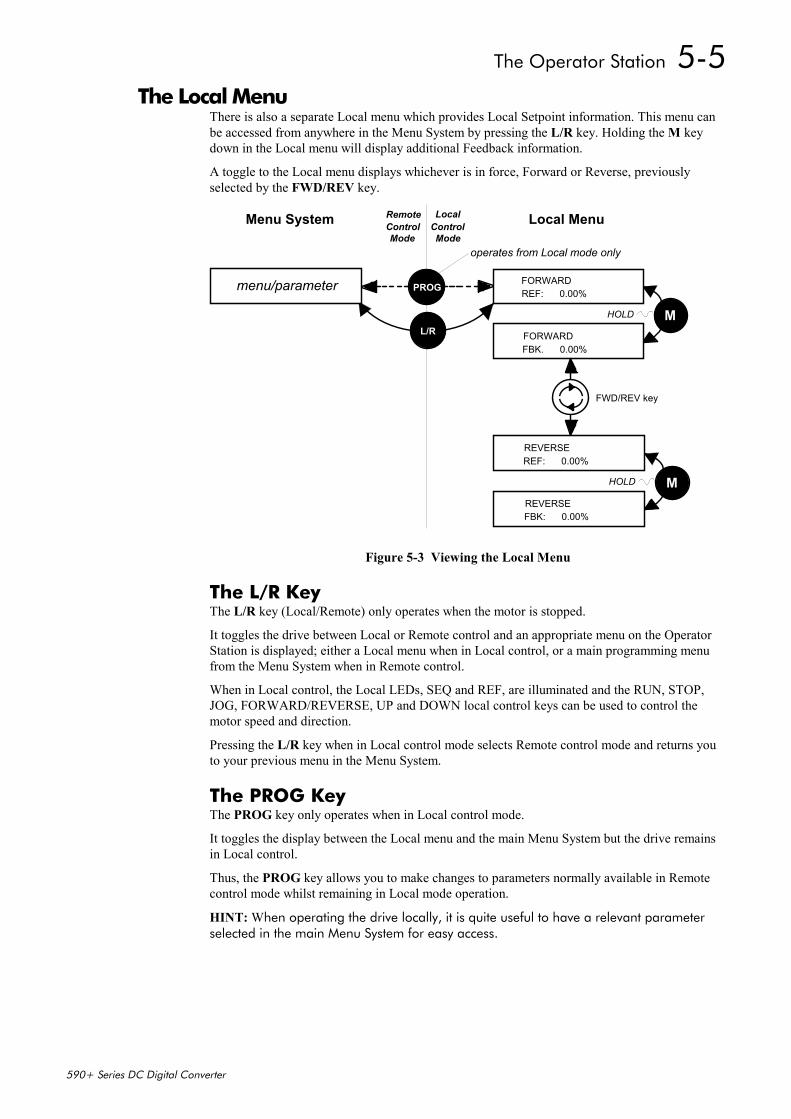
The Operator Station 5-5
590+ Series DC Digital Converter
The Local MenuThere is also a separate Local menu which provides Local Setpoint information. This menu canbe accessed from anywhere in the Menu System by pressing the L/R key. Holding the M keydown in the Local menu will display additional Feedback information.
A toggle to the Local menu displays whichever is in force, Forward or Reverse, previouslyselected by the FWD/REV key.
HOLD
Menu System
FORWARDREF: 0.00%
FORWARDFBK. 0.00%
operates from Local mode only
PROG
ML/R
HOLD
REVERSEFBK: 0.00%
REVERSEREF: 0.00%
M
LocalRemoteControl Control Local Menu
FWD/REV key
menu/parameter
Mode Mode
Figure 5-3 Viewing the Local Menu
The L/R KeyThe L/R key (Local/Remote) only operates when the motor is stopped.
It toggles the drive between Local or Remote control and an appropriate menu on the OperatorStation is displayed; either a Local menu when in Local control, or a main programming menufrom the Menu System when in Remote control.
When in Local control, the Local LEDs, SEQ and REF, are illuminated and the RUN, STOP,JOG, FORWARD/REVERSE, UP and DOWN local control keys can be used to control themotor speed and direction.
Pressing the L/R key when in Local control mode selects Remote control mode and returns youto your previous menu in the Menu System.
The PROG KeyThe PROG key only operates when in Local control mode.
It toggles the display between the Local menu and the main Menu System but the drive remainsin Local control.
Thus, the PROG key allows you to make changes to parameters normally available in Remotecontrol mode whilst remaining in Local mode operation.
HINT: When operating the drive locally, it is quite useful to have a relevant parameterselected in the main Menu System for easy access.
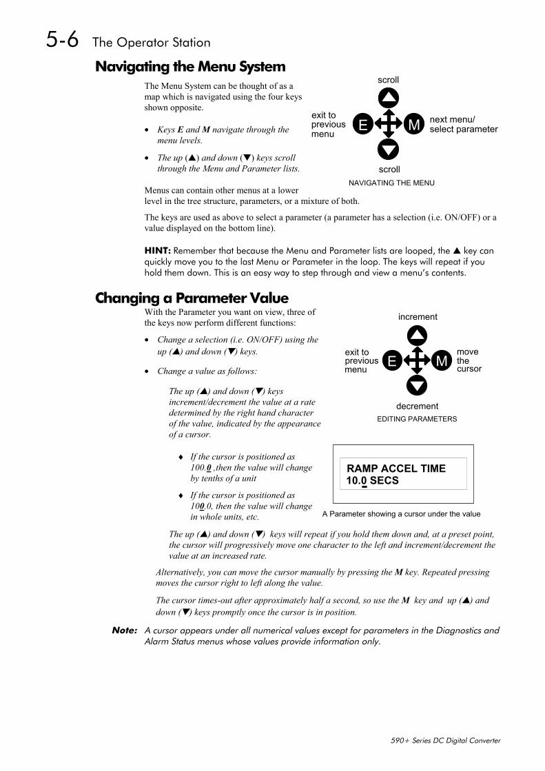
5-6 The Operator Station
590+ Series DC Digital Converter
Navigating the Menu SystemThe Menu System can be thought of as amap which is navigated using the four keysshown opposite.
• Keys E and M navigate through themenu levels.
• The up () and down () keys scrollthrough the Menu and Parameter lists.
Menus can contain other menus at a lowerlevel in the tree structure, parameters, or a mixture of both.
The keys are used as above to select a parameter (a parameter has a selection (i.e. ON/OFF) or avalue displayed on the bottom line).
HINT: Remember that because the Menu and Parameter lists are looped, the key canquickly move you to the last Menu or Parameter in the loop. The keys will repeat if youhold them down. This is an easy way to step through and view a menu’s contents.
Changing a Parameter ValueWith the Parameter you want on view, three ofthe keys now perform different functions:
• Change a selection (i.e. ON/OFF) using theup () and down () keys.
• Change a value as follows:
The up () and down () keysincrement/decrement the value at a ratedetermined by the right hand characterof the value, indicated by the appearanceof a cursor.
♦ If the cursor is positioned as100.0 ,then the value will changeby tenths of a unit
♦ If the cursor is positioned as100.0, then the value will changein whole units, etc.
The up () and down () keys will repeat if you hold them down and, at a preset point,the cursor will progressively move one character to the left and increment/decrement thevalue at an increased rate.
Alternatively, you can move the cursor manually by pressing the M key. Repeated pressingmoves the cursor right to left along the value.
The cursor times-out after approximately half a second, so use the M key and up () anddown () keys promptly once the cursor is in position.
Note: A cursor appears under all numerical values except for parameters in the Diagnostics andAlarm Status menus whose values provide information only.
increment
decrement
thecursor
exit topreviousmenu
EDITING PARAMETERS
E Mmove
11
RAMP ACCEL TIME10.0 SECS
A Parameter showing a cursor under the value
scroll
scroll
exit topreviousmenu
next menu/
NAVIGATING THE MENU
E M select parameter
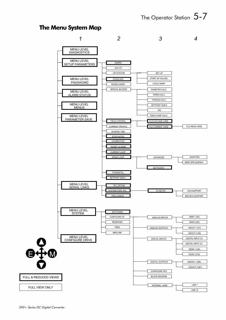
The Operator Station 5-7
590+ Series DC Digital Converter
The Menu System Map
MENU LEVELPASSWORD
MENU LEVELALARM STATUS
MENU LEVELMENUS
MENU LEVELPARAMETER SAVE
MENU LEVELSETUP PARAMETERS
MENU LEVELDIAGNOSTICS
CONFIGURE I/O
RESERVED
PEEK
SOFTWAREMENU LEVELSYSTEM
MENU LEVELSERIAL LINKS
MINI LINK
SYSTEM PORT (P3)
PNO CONFIG
TEC OPTION
FIELD CONTROL
RAMPS
AUX I/O
JOG/SLACK
RAISE/LOWER
SPECIAL BLOCKS
INVERSE TIME
STOP RATES
CALIBRATION
INHIBIT ALARMS
CURRENT LOOP
SPEED LOOP
STANDSTILL
SETPOINT SUM 1
ANIN 1 (A2)
ANIN 5 (A6)
ANOUT 1 (A7)
ANOUT 2 (A8)
DIGITAL INPUT C4
DIGITAL INPUT C5
DIGIN 1 (C6)
DIGIN 3 (C8)
DIGOUT 1 (B5)
DIGOUT 3 (B7)
LINK 1
LINK 12
FLD WEAK VARS
ADAPTION
ZERO SPD.QUENCH
FLD VOLTAGE VARS
FLD CURRENT VARS
DIAMETER CALC.
TAPER CALC.
TORQUE CALC.
SETPOINT SUM 2
PID
TENS+COMP CALC.
ADVANCED
SETPOINTS
DIGITAL OUTPUTS
CONFIGURE 5703
BLOCK DIAGRAM
ANALOG INPUTS
ANALOG OUTPUTS
DIGITAL INPUTS
INTERNAL LINKSFULL VIEW ONLY
FULL & REDUCED VIEWS
1 2 3 4
E M
OP-STATION SET UP
START UP VALUES
LOCAL RAMP
CURRENT PROFILE
MENU LEVELCONFIGURE DRIVE
5703 SUPPORT
BISYNCH SUPPORT
P3 SETUP
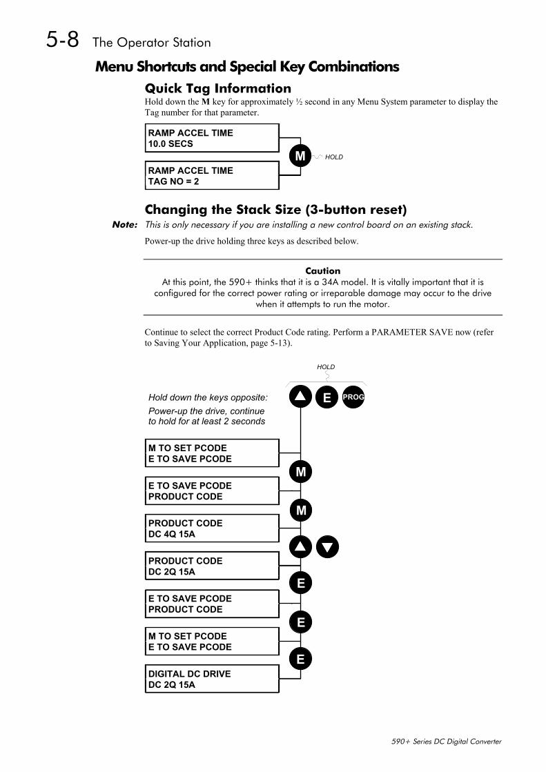
5-8 The Operator Station
590+ Series DC Digital Converter
Menu Shortcuts and Special Key CombinationsQuick Tag InformationHold down the M key for approximately ½ second in any Menu System parameter to display theTag number for that parameter.
RAMP ACCEL TIME10.0 SECS
RAMP ACCEL TIMETAG NO = 2
M HOLD
Changing the Stack Size (3-button reset)Note: This is only necessary if you are installing a new control board on an existing stack.
Power-up the drive holding three keys as described below.
Caution At this point, the 590+ thinks that it is a 34A model. It is vitally important that it is
configured for the correct power rating or irreparable damage may occur to the drivewhen it attempts to run the motor.
Continue to select the correct Product Code rating. Perform a PARAMETER SAVE now (referto Saving Your Application, page 5-13).
Hold down the keys opposite:Power-up the drive, continueto hold for at least 2 seconds
M TO SET PCODEE TO SAVE PCODE
E TO SAVE PCODEPRODUCT CODE
PRODUCT CODEDC 4Q 15A
PRODUCT CODEDC 2Q 15A
E TO SAVE PCODEPRODUCT CODE
M TO SET PCODEE TO SAVE PCODE
DIGITAL DC DRIVEDC 2Q 15A
E PROG
M
M
E
E
E
HOLD
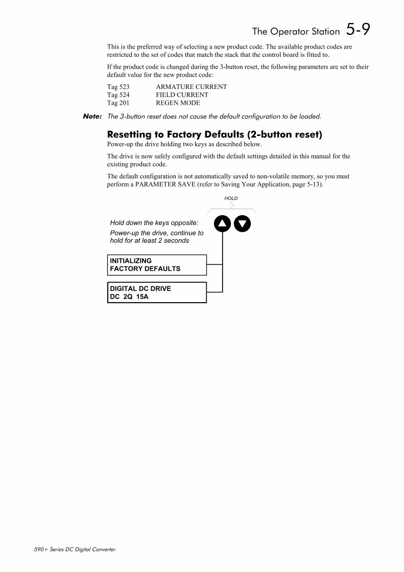
The Operator Station 5-9
590+ Series DC Digital Converter
This is the preferred way of selecting a new product code. The available product codes arerestricted to the set of codes that match the stack that the control board is fitted to.
If the product code is changed during the 3-button reset, the following parameters are set to theirdefault value for the new product code:
Tag 523 ARMATURE CURRENTTag 524 FIELD CURRENTTag 201 REGEN MODE
Note: The 3-button reset does not cause the default configuration to be loaded.
Resetting to Factory Defaults (2-button reset)Power-up the drive holding two keys as described below.
The drive is now safely configured with the default settings detailed in this manual for theexisting product code.
The default configuration is not automatically saved to non-volatile memory, so you mustperform a PARAMETER SAVE (refer to Saving Your Application, page 5-13).
Hold down the keys opposite:Power-up the drive, continue tohold for at least 2 seconds
INITIALIZINGFACTORY DEFAULTS
DIGITAL DC DRIVEDC 2Q 15A
HOLD

5-10 The Operator Station
590+ Series DC Digital Converter
Special Menu Features
Selecting a Menu Viewing LevelFor ease of operation there are two `viewing levels` for the MMI: fullview or reduced view. The setting for the viewing level decides howmuch of the menu system will be displayed.
Refer to the Menu System Map, page 5-5 to see how the viewing levelchanges the displayed menu.
To change the viewing level, go to the MENUS menu. The first parameter in this menu, FULLMENUS selects the viewing level.
• Select DISABLED to use the reduced menu system.• Select ENABLED to use the full menu system.
MENUSFULL MENUS
FULL MENUSENABLED
FULL MENUSDISABLED
MENUSFULL MENUS
M
E
Selecting the Display LanguageThere is an option to select a different display language.
The choice of display language is selected by the LANGUAGEparameter in the MENUS menu. Remember to perform aPARAMETER SAVE if you need the new language to be saved onpower-down.
ENGLISH is the default language and is permanently saved (in Read Only Memory).
A second language is loaded (typically French), however German, Italian and Spanish areavailable by contacting Eurotherm Drives. When a new language is downloaded it replaces thecurrent second language.
MENUSLANGUAGE
LANGUAGEENGLISH
LANGUAGEother
menuslanguage
M
E
MMI Menu Map1 MENUS
FULL MENUSLANGUAGE
MMI Menu Map1 MENUS
FULL MENUSLANGUAGE
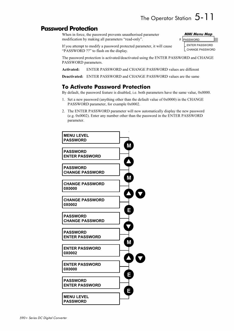
The Operator Station 5-11
590+ Series DC Digital Converter
Password ProtectionWhen in force, the password prevents unauthorised parametermodification by making all parameters “read-only”.
If you attempt to modify a password protected parameter, it will cause“PASSWORD ??” to flash on the display.
The password protection is activated/deactivated using the ENTER PASSWORD and CHANGEPASSWORD parameters.
Activated: ENTER PASSWORD and CHANGE PASSWORD values are different
Deactivated: ENTER PASSWORD and CHANGE PASSWORD values are the same
To Activate Password ProtectionBy default, the password feature is disabled, i.e. both parameters have the same value, 0x0000.
1. Set a new password (anything other than the default value of 0x0000) in the CHANGEPASSWORD parameter, for example 0x0002.
2. The ENTER PASSWORD parameter will now automatically display the new password(e.g. 0x0002). Enter any number other than the password in the ENTER PASSWORDparameter.
MENU LEVELPASSWORD
PASSWORDENTER PASSWORD
PASSWORDCHANGE PASSWORD
CHANGE PASSWORD0X0000
CHANGE PASSWORD0X0002
PASSWORDCHANGE PASSWORD
PASSWORDENTER PASSWORD
M
M
E
ENTER PASSWORD0X0002
ENTER PASSWORD0X0000
PASSWORDENTER PASSWORD
MENU LEVELPASSWORD
M
E
E
MMI Menu Map1 PASSWORD
ENTER PASSWORDCHANGE PASSWORD
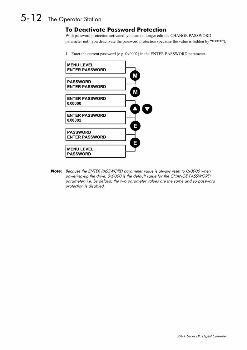
5-12 The Operator Station
590+ Series DC Digital Converter
To Deactivate Password ProtectionWith password protection activated, you can no longer edit the CHANGE PASSWORDparameter until you deactivate the password protection (because the value is hidden by “****”).
1. Enter the current password (e.g. 0x0002) in the ENTER PASSWORD parameter.
MENU LEVELENTER PASSWORD
PASSWORDENTER PASSWORD
ENTER PASSWORD0X0000
ENTER PASSWORD0X0002
PASSWORDENTER PASSWORD
MENU LEVELPASSWORD
M
E
E
M
Note: Because the ENTER PASSWORD parameter value is always reset to 0x0000 whenpowering-up the drive, 0x0000 is the default value for the CHANGE PASSWORDparameter, i.e. by default, the two parameter values are the same and so passwordprotection is disabled.
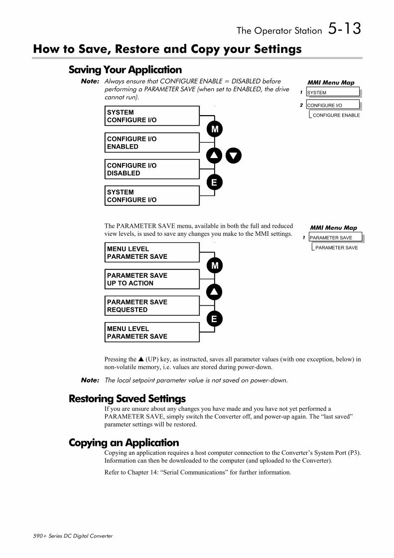
The Operator Station 5-13
590+ Series DC Digital Converter
How to Save, Restore and Copy your Settings
Saving Your ApplicationNote: Always ensure that CONFIGURE ENABLE = DISABLED before
performing a PARAMETER SAVE (when set to ENABLED, the drivecannot run).
SYSTEMCONFIGURE I/O
CONFIGURE I/OENABLED
CONFIGURE I/ODISABLED
SYSTEMCONFIGURE I/O
M
E
The PARAMETER SAVE menu, available in both the full and reducedview levels, is used to save any changes you make to the MMI settings.
MENU LEVELPARAMETER SAVE
PARAMETER SAVEUP TO ACTION
PARAMETER SAVEREQUESTED
MENU LEVELPARAMETER SAVE
M
E
Pressing the (UP) key, as instructed, saves all parameter values (with one exception, below) innon-volatile memory, i.e. values are stored during power-down.
Note: The local setpoint parameter value is not saved on power-down.
Restoring Saved SettingsIf you are unsure about any changes you have made and you have not yet performed aPARAMETER SAVE, simply switch the Converter off, and power-up again. The “last saved”parameter settings will be restored.
Copying an ApplicationCopying an application requires a host computer connection to the Converter’s System Port (P3).Information can then be downloaded to the computer (and uploaded to the Converter).
Refer to Chapter 14: “Serial Communications” for further information.
MMI Menu Map
1 SYSTEM
2 CONFIGURE I/O
CONFIGURE ENABLE
MMI Menu Map
1 PARAMETER SAVE
PARAMETER SAVE

5-14 The Operator Station
590+ Series DC Digital Converter

Programming Your Application 6-1
590+ Series DC Digital Converter
6 PROGRAMMING YOUR APPLICATIONProgramming with Block Diagrams
You can program the Converter for specific applications using the MMI or suitable programmingtool, such as “ConfigEd Lite” which is Eurotherm Drives’ block programming software.
The Converter is supplied with a basic set-up which can be used as a starting point forapplication-specific programming. This programming could simply involve the inputting ofparameter values, or it may require the making or breaking of programmable links, which is afeature of this unit.
Block diagram programming provides a visual method of planning the software to suit yourapplication. The basic block diagram is provided in Chapter 15 and shows the softwareconnections consisting of function blocks and links:
• Each function block contains the parameters required for setting-up a particular processingfeature. Sometimes more than one function block is provided for a feature, i.e. for multipledigital inputs.
• Software links are used to connect the function blocks. Each link transfers the value of anoutput parameter to an input parameter of another (or the same) function block.
Each individual block is a processing feature, i.e. it takes the input parameter, processes theinformation, and makes the result available as one or more output parameters.
Modifying a Block DiagramConfiguration and Parameterisation ModesThere are two modes of operation used while modifying a blockdiagram: Parameterisation and Configuration modes.
The CONFIGURE ENABLE command is used to toggle betweenthese two modes of operation.
Parameterisation Mode (CONFIGURE ENABLE =DISABLED)In parameterisation mode you can change parameter values. The Converter can berunning or stopped. Note that some parameters can only be changed when theConverter is stopped. It is not possible to modify the internal links when the Converteris in parameterisation mode.
Configuration Mode (CONFIGURE ENABLE = ENABLED) In the configuration mode you can modify the links in the function block diagram. Youcan also change parameter values, as above. The Converter cannot run in this mode.Output values are not updated.
Making and Breaking Links in Configuration ModeLinks can be moved, added or deleted from a block diagram whilst in the Configuration mode.There are 12 general-purpose links available, each has its own identification number (“link”number). You make a link by setting the link’s “source” and “destination” tags to be the twoparameter tag numbers to be linked. The outputs of function blocks are not updated whilst in thismode.
Note: Links 11 and 12 can be configured to perform one of a number of basic functions uponthe source and/or auxiliary source tag values, to be output at the selected destination tag.
Special LinksIn addition to these 12 general-purpose links, there are some links permanently associated withparticular input parameters. It is only necessary to enter the source tag number to activate theselinks. Similarly, there are some links permanently associated with particular output parameters. Itis only necessary to enter the destination tag number to activate these links.
All these links may be found in the SYSTEM::CONFIGURE I/O menu.
MMI Menu Map
1 SYSTEM
2 CONFIGURE I/O
CONFIGURE ENABLE
DEFAULT
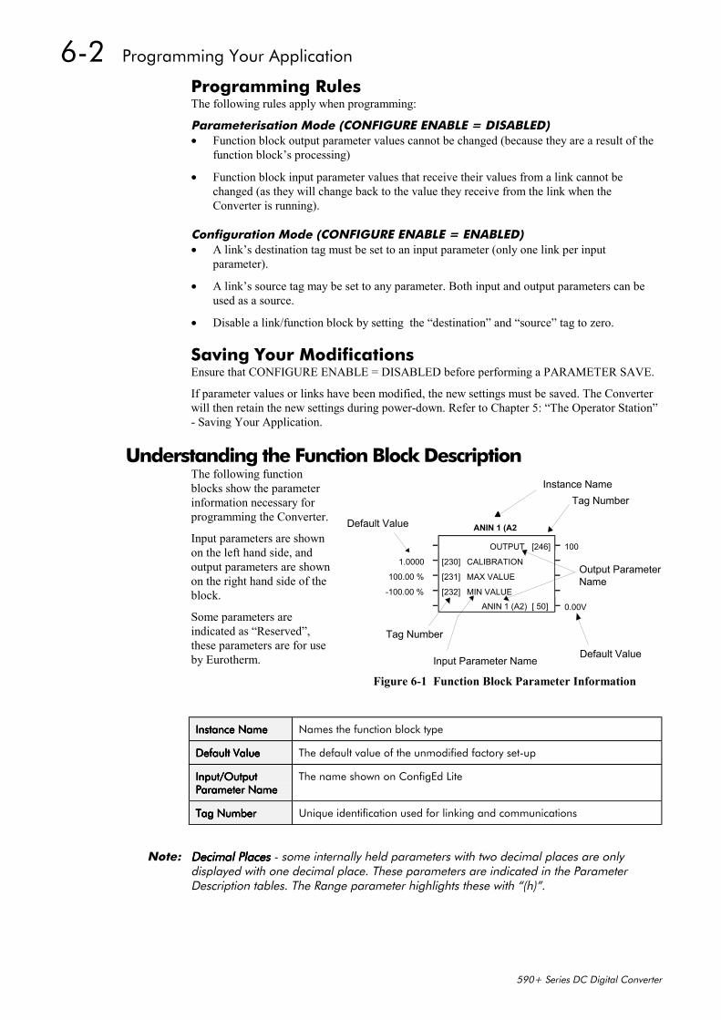
6-2 Programming Your Application
590+ Series DC Digital Converter
Programming RulesThe following rules apply when programming:
Parameterisation Mode (CONFIGURE ENABLE = DISABLED)• Function block output parameter values cannot be changed (because they are a result of the
function block’s processing)
• Function block input parameter values that receive their values from a link cannot bechanged (as they will change back to the value they receive from the link when theConverter is running).
Configuration Mode (CONFIGURE ENABLE = ENABLED)• A link’s destination tag must be set to an input parameter (only one link per input
parameter).
• A link’s source tag may be set to any parameter. Both input and output parameters can beused as a source.
• Disable a link/function block by setting the “destination” and “source” tag to zero.
Saving Your ModificationsEnsure that CONFIGURE ENABLE = DISABLED before performing a PARAMETER SAVE.
If parameter values or links have been modified, the new settings must be saved. The Converterwill then retain the new settings during power-down. Refer to Chapter 5: “The Operator Station”- Saving Your Application.
Understanding the Function Block DescriptionThe following functionblocks show the parameterinformation necessary forprogramming the Converter.
Input parameters are shownon the left hand side, andoutput parameters are shownon the right hand side of theblock.
Some parameters areindicated as “Reserved”,these parameters are for useby Eurotherm.
Instance NameInstance NameInstance NameInstance Name Names the function block type
Default ValueDefault ValueDefault ValueDefault Value The default value of the unmodified factory set-up
Input/OutputInput/OutputInput/OutputInput/OutputParameter NameParameter NameParameter NameParameter Name
The name shown on ConfigEd Lite
Tag NumberTag NumberTag NumberTag Number Unique identification used for linking and communications
Note: Decimal PlacesDecimal PlacesDecimal PlacesDecimal Places - some internally held parameters with two decimal places are onlydisplayed with one decimal place. These parameters are indicated in the ParameterDescription tables. The Range parameter highlights these with “(h)”.
Input Parameter Name
Output ParameterName
Default Value
Default Value
Instance Name
Tag Number
ANIN 1 (A2
– OUTPUT [246] 100
1.0000 – [230] CALIBRATION
100.00 % – [231] MAX VALUE
-100.00 % – [232] MIN VALUE– ANIN 1 (A2)
––––– 0.00V[ 50]
Tag Number
Figure 6-1 Function Block Parameter Information

Programming Your Application 6-3
590+ Series DC Digital Converter
MMI Menu MapsThe function block descriptions include an easy-find menu showing the menu levels and titlesencountered to find the appropriate menu title, and the parameters contained in the menu(s).
The menu maps are shown as if the full view level is selected.
Where there is more than one sub-menu, i.e. ANALOG INPUTS as illustrated, the parametersshown will be for the last sub-menu. In many cases, these parameters will reflect the name andnumber of the last sub-menu.
Because of this intuitive naming of parameters, which is designed to make using the OperatorStation easier, MMI parameter names may vary slightly from Function Block names.
A function block may also be represented by more than one MMI menu, e.g. FIELDCONTROL. In contrast, the DIAGNOSTICS menu on the MMI is greatly reduced in theDIAGNOSTICS function block, the remaining parameters being included in related functionblocks.
MMI Menu Map
1 SYSTEM
2 CONFIGURE I/O
3 ANALOG INPUTS
4 ANIN 1 (A2)
4 ANIN 5 (A6)
CALIBRATIONMAX VALUEMIN VALUEDESTINATION TAG
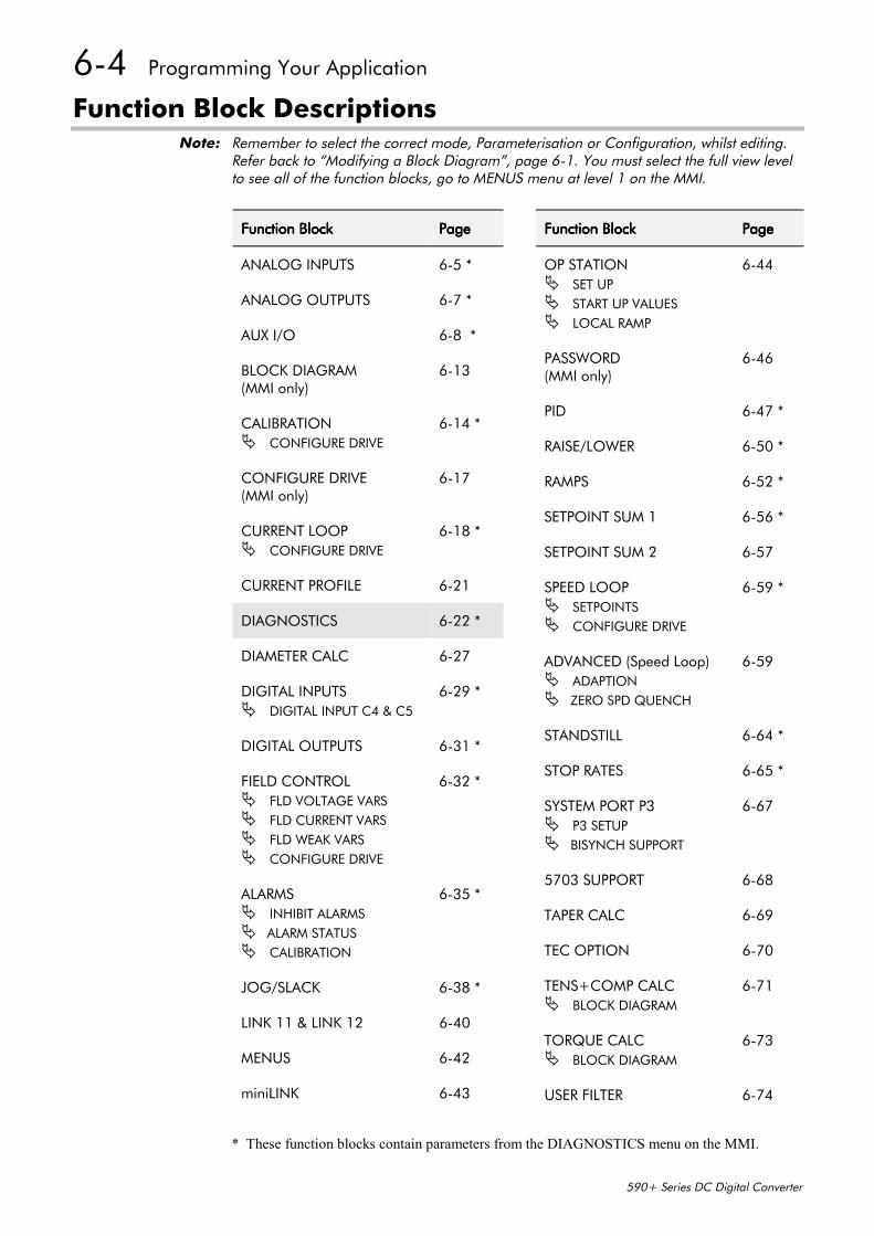
6-4 Programming Your Application
590+ Series DC Digital Converter
Function Block DescriptionsNote: Remember to select the correct mode, Parameterisation or Configuration, whilst editing.
Refer back to “Modifying a Block Diagram”, page 6-1. You must select the full view levelto see all of the function blocks, go to MENUS menu at level 1 on the MMI.
* These function blocks contain parameters from the DIAGNOSTICS menu on the MMI.
Function BlockFunction BlockFunction BlockFunction Block PagePagePagePage
OP STATION SET UP START UP VALUES LOCAL RAMP
6-44
PASSWORD(MMI only)
6-46
PID 6-47 *
RAISE/LOWER 6-50 *
RAMPS 6-52 *
SETPOINT SUM 1 6-56 *
SETPOINT SUM 2 6-57
SPEED LOOP SETPOINTS CONFIGURE DRIVE
6-59 *
ADVANCED (Speed Loop) ADAPTION ZERO SPD QUENCH
6-59
STANDSTILL 6-64 *
STOP RATES 6-65 *
SYSTEM PORT P3 P3 SETUP BISYNCH SUPPORT
6-67
5703 SUPPORT 6-68
TAPER CALC 6-69
TEC OPTION 6-70
TENS+COMP CALC BLOCK DIAGRAM
6-71
TORQUE CALC BLOCK DIAGRAM
6-73
USER FILTER 6-74
Function BlockFunction BlockFunction BlockFunction Block PagePagePagePage
ANALOG INPUTS 6-5 *
ANALOG OUTPUTS 6-7 *
AUX I/O 6-8 *
BLOCK DIAGRAM(MMI only)
6-13
CALIBRATION CONFIGURE DRIVE
6-14 *
CONFIGURE DRIVE(MMI only)
6-17
CURRENT LOOP CONFIGURE DRIVE
6-18 *
CURRENT PROFILE 6-21
DIAGNOSTICS 6-22 *
DIAMETER CALC 6-27
DIGITAL INPUTS DIGITAL INPUT C4 & C5
6-29 *
DIGITAL OUTPUTS 6-31 *
FIELD CONTROL FLD VOLTAGE VARS FLD CURRENT VARS FLD WEAK VARS CONFIGURE DRIVE
6-32 *
ALARMS INHIBIT ALARMS ALARM STATUS CALIBRATION
6-35 *
JOG/SLACK 6-38 *
LINK 11 & LINK 12 6-40
MENUS 6-42
miniLINK 6-43

Programming Your Application 6-5
590+ Series DC Digital Converter
ANALOG INPUTS
The analog input block is used to scale andclamp the inputs for terminals A2 to A6.
Note: ANIN 2 (A3) is not reconfigurable and is connected directly to the SETUP PARAMETERS::SPEED LOOP:: SETPOINTS:: RATIO 2 (A3) input, and the SETUP PARAMETER:: CURRENTLOOP:: I DMD. ISOLATE switch. Refer to Chapter 15: “The Default Application” - MainBlock Diagram for more information.
Tag 493 allows access to the calibrated value of ANIN 2 (via an internal link forexample). To avoid interference with other drive functions the parameter RATIO 2 (A3)must be set to zero, and the I DMD. ISOLATE parameter must be set to DISABLED, i.e.selecting the Speed Loop as shown in the Main Block Diagram.
ANIN 2 (A3) is a direct input into the speed loop/current loop and is scannedsynchronously with the current loop (typically every 3.33ms) rather than every micro cycletime (typically 7ms). Therefore it should be used for any signal whose response is criticale.g. a trim input from a digital speed and position locking system.
MMI Menu Map
1 SYSTEM
2 CONFIGURE I/O
3 ANALOG INPUTS
4 ANIN 1 (A2)
4 ANIN 2 (A3)
4 ANIN 3 (A4)
4 ANIN 4 (A5)
4 ANIN 5 (A6)
CALIBRATIONMAX VALUEMIN VALUEDESTINATION TAG
Analog Input 1– OUTPUT [246] – 100– [230] CALIBRATION –
100.00 % – [231] MAX VALUE –-100.00 % – [232] MIN VALUE –
– ANIN 1 (A2) [ 50] – 0.00 VOLTS
Analog Input 21.0000 – [233] CALIBRATION –
100.00 % – [234] MAX VALUE –-100.00 % – [235] MIN VALUE –
– ANIN 2 (A3) [ 51] – 0.00 VOLTS
Analog Input 3– OUTPUT [249] – 5
1.0000 – [236] CALIBRATION –100.00 % – [237] MAX VALUE –
-100.00 % – [238] MIN VALUE –– ANIN 3 (A4) [ 52] – 0.00 VOLTS
Analog Input 4– OUTPUT [250] – 48
1.0000 – [239] CALIBRATION –100.00 % – [240] MAX VALUE –
-100.00 % – [241] MIN VALUE –– ANIN 4 (A5) [ 53] – 0.00 VOLTS
Analog Input 5– OUTPUT [247] – 301
1.0000 – [242] CALIBRATION –100.00 % – [243] MAX VALUE –
-100.00 % – [244] MIN VALUE –– ANIN 5 (A6) [ 54] – 0.00 VOLTS
Parameter DescriptionsOUTPUT Range: 0 to 549
(DESTINATION TAG)The destination Tag No. of the scaled analog input value. Refer to “Special Links”, page 6-1.
CALIBRATION Range: -3.0000 to 3.0000
The analog input scaling ratio.
MAX VALUE Range: -300.00 to 300.00 %
The maximum value of the scaled analog input.
MIN VALUE Range: -300.00 to 300.00 %
The minimum value of the scaled analog input
ANIN 1 (A2) to ANIN 5 (A6) Range: xxx.xx VOLTS
Refer to the DIAGNOSTICS function block description, page 6-22.
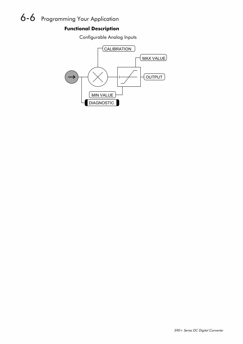
6-6 Programming Your Application
590+ Series DC Digital Converter
Functional Description
Configurable Analog Inputs
OUTPUT
MIN VALUE
MAX VALUE
0
DIAGNOSTIC
CALIBRATION
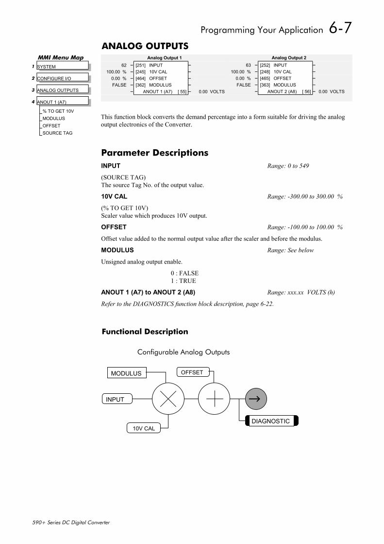
Programming Your Application 6-7
590+ Series DC Digital Converter
ANALOG OUTPUTS
This function block converts the demand percentage into a form suitable for driving the analogoutput electronics of the Converter.
Functional Description
Configurable Analog Outputs
INPUT
DIAGNOSTIC
MODULUS OFFSET
10V CAL
Analog Output 263 – [252] INPUT –
100.00 % – [248] 10V CAL –0.00 % – [465] OFFSET –FALSE – [363] MODULUS –
– ANOUT 2 (A8) [ 56] – 0.00 VOLTS
Analog Output 162 – [251] INPUT –
100.00 % – [245] 10V CAL –0.00 % – [464] OFFSET –FALSE – [362] MODULUS –
– ANOUT 1 (A7) [ 55] – 0.00 VOLTS
MMI Menu Map 1 SYSTEM
2 CONFIGURE I/O
3 ANALOG OUTPUTS
4 ANOUT 1 (A7)
% TO GET 10VMODULUSOFFSETSOURCE TAG
Parameter DescriptionsINPUT Range: 0 to 549
(SOURCE TAG)The source Tag No. of the output value.
10V CAL Range: -300.00 to 300.00 %
(% TO GET 10V)Scaler value which produces 10V output.
OFFSET Range: -100.00 to 100.00 %
Offset value added to the normal output value after the scaler and before the modulus.
MODULUS Range: See below
Unsigned analog output enable.
0 : FALSE1 : TRUE
ANOUT 1 (A7) to ANOUT 2 (A8) Range: xxx.xx VOLTS (h)
Refer to the DIAGNOSTICS function block description, page 6-22.
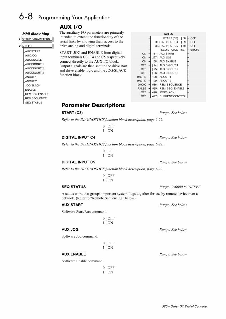
6-8 Programming Your Application
590+ Series DC Digital Converter
AUX I/OThe auxiliary I/O parameters are primarilyintended to extend the functionality of theserial links by allowing them access to thedrive analog and digital terminals.
START, JOG and ENABLE from digitalinput terminals C3, C4 and C5 respectivelyconnect directly to the AUX I/O block.Output signals are then sent to the drive startand drive enable logic and the JOG/SLACKfunction block.
Aux I/O– START (C3) [ 68] – OFF– DIGITAL INPUT C4 [ 69] – OFF– DIGITAL INPUT C5 [ 70] – OFF– SEQ STATUS [537] – 0x0000
ON – [161] AUX START –ON – [227] AUX JOG –ON – [168] AUX ENABLE –
OFF – [ 94] AUX DIGOUT 1 –OFF – [ 95] AUX DIGOUT 2 –OFF – [ 96] AUX DIGOUT 3 –
0.00 % – [128] ANOUT 1 –0.00 % – [129] ANOUT 2 –0x0000 – [536] REM. SEQUENCE –FALSE – [535] REM. SEQ. ENABLE –
OFF – [496] JOG/SLACK –OFF – [497] CURRENT CONTROL –
MMI Menu Map 1 SETUP PARAMETERS
2 AUX I/O
AUX STARTAUX JOGAUX ENABLEAUX DIGOUT 1AUX DIGOUT 2AUX DIGOUT 3ANOUT 1ANOUT 2JOG/SLACKENABLEREM.SEQ.ENABLEREM.SEQUENCESEQ STATUS
Parameter DescriptionsSTART (C3) Range: See below
Refer to the DIAGNOSTICS function block description, page 6-22.
0 : OFF1 : ON
DIGITAL INPUT C4 Range: See below
Refer to the DIAGNOSTICS function block description, page 6-22.
0 : OFF1 : ON
DIGITAL INPUT C5 Range: See below
Refer to the DIAGNOSTICS function block description, page 6-22.
0 : OFF1 : ON
SEQ STATUS Range: 0x0000 to 0xFFFF
A status word that groups important system flags together for use by remote device over anetwork. (Refer to “Remote Sequencing” below).
AUX START Range: See below
Software Start/Run command.
0 : OFF1 : ON
AUX JOG Range: See below
Software Jog command.
0 : OFF1 : ON
AUX ENABLE Range: See below
Software Enable command.
0 : OFF1 : ON
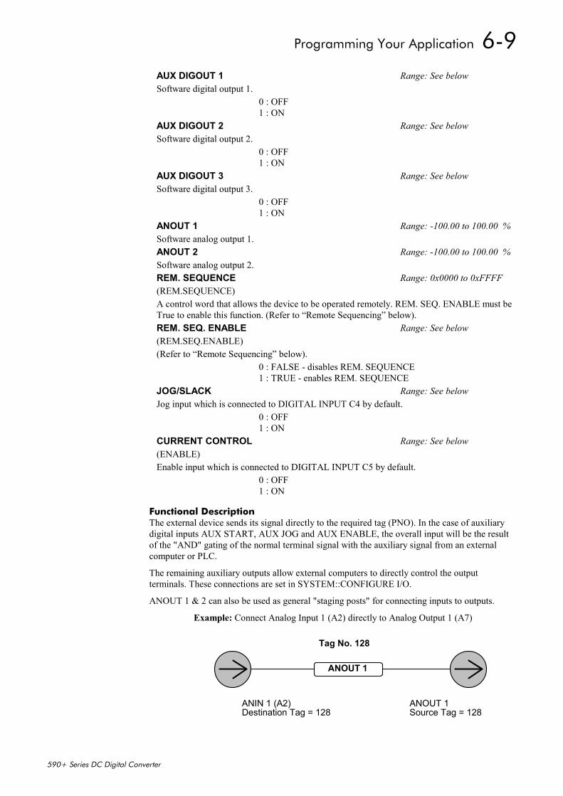
Programming Your Application 6-9
590+ Series DC Digital Converter
Functional DescriptionThe external device sends its signal directly to the required tag (PNO). In the case of auxiliarydigital inputs AUX START, AUX JOG and AUX ENABLE, the overall input will be the resultof the "AND" gating of the normal terminal signal with the auxiliary signal from an externalcomputer or PLC.
The remaining auxiliary outputs allow external computers to directly control the outputterminals. These connections are set in SYSTEM::CONFIGURE I/O.
ANOUT 1 & 2 can also be used as general "staging posts" for connecting inputs to outputs.
Example: Connect Analog Input 1 (A2) directly to Analog Output 1 (A7)
AUX DIGOUT 1 Range: See belowSoftware digital output 1.
0 : OFF1 : ON
AUX DIGOUT 2 Range: See belowSoftware digital output 2.
0 : OFF1 : ON
AUX DIGOUT 3 Range: See belowSoftware digital output 3.
0 : OFF1 : ON
ANOUT 1 Range: -100.00 to 100.00 %Software analog output 1.ANOUT 2 Range: -100.00 to 100.00 %Software analog output 2.REM. SEQUENCE Range: 0x0000 to 0xFFFF(REM.SEQUENCE)A control word that allows the device to be operated remotely. REM. SEQ. ENABLE must beTrue to enable this function. (Refer to “Remote Sequencing” below).REM. SEQ. ENABLE Range: See below(REM.SEQ.ENABLE)(Refer to “Remote Sequencing” below).
0 : FALSE - disables REM. SEQUENCE1 : TRUE - enables REM. SEQUENCE
JOG/SLACK Range: See belowJog input which is connected to DIGITAL INPUT C4 by default.
0 : OFF1 : ON
CURRENT CONTROL Range: See below(ENABLE)Enable input which is connected to DIGITAL INPUT C5 by default.
0 : OFF1 : ON
ANOUT 1
Destination Tag = 128 Source Tag = 128ANIN 1 (A2) ANOUT 1
Tag No. 128
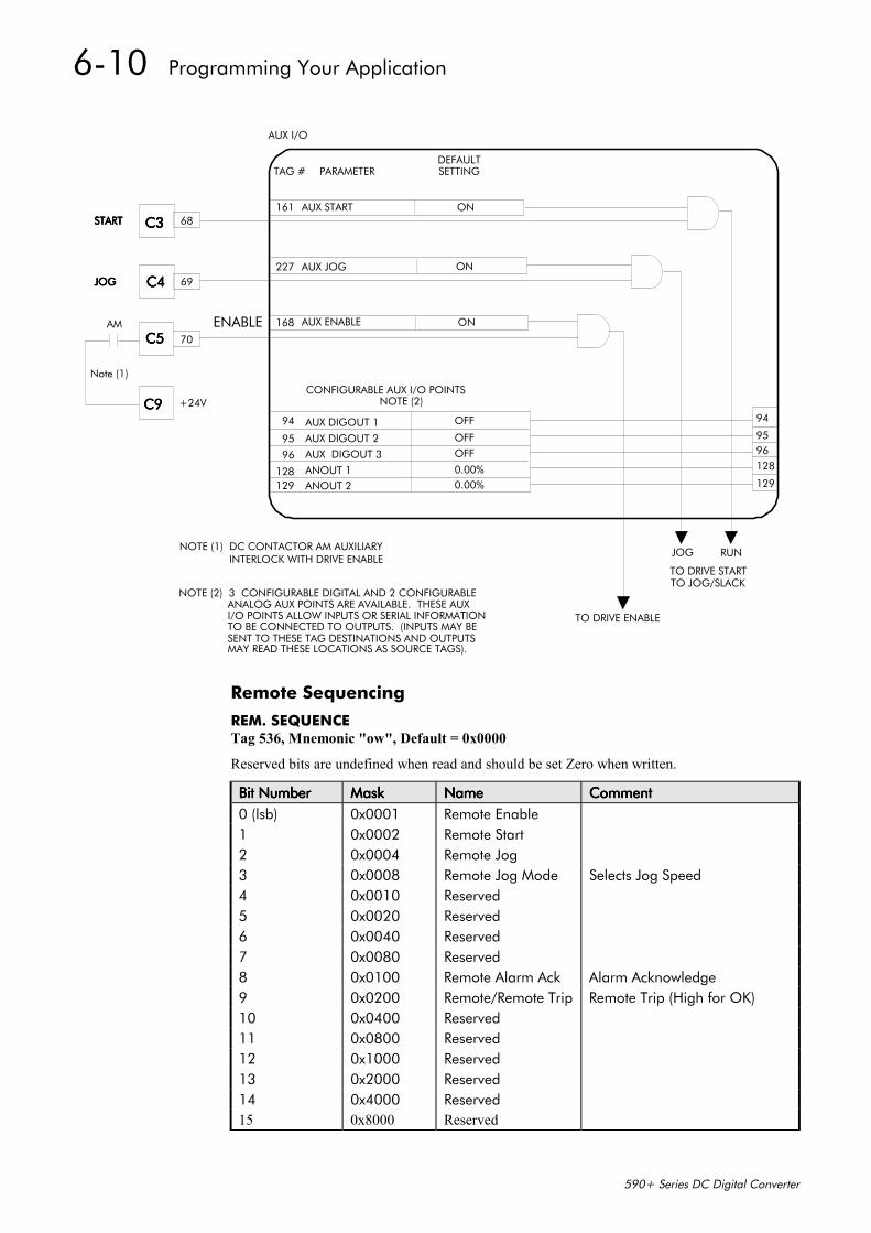
6-10 Programming Your Application
590+ Series DC Digital Converter
TAG # PARAMETERDEFAULTSETTING
161 AUX START ON
227 AUX JOG ON
168 AUX ENABLE ON
CONFIGURABLE AUX I/O POINTSNOTE (2)
94 AUX DIGOUT 1 OFF
95 AUX DIGOUT 2 OFF
96 AUX DIGOUT 3 OFF
128 ANOUT 1129 ANOUT 2
0.00%0.00%
94
9596128
129
AUX I/O
JOG RUN
TO DRIVE ENABLE
NOTE (1) DC CONTACTOR AM AUXILIARYINTERLOCK WITH DRIVE ENABLE
68C3C3C3C3STARTSTARTSTARTSTART
69C4C4C4C4JOGJOGJOGJOG
70C5C5C5C5AM
C9C9C9C9
Note (1)
+24V
NOTE (2) 3 CONFIGURABLE DIGITAL AND 2 CONFIGURABLEANALOG AUX POINTS ARE AVAILABLE. THESE AUXI/O POINTS ALLOW INPUTS OR SERIAL INFORMATIONTO BE CONNECTED TO OUTPUTS. (INPUTS MAY BESENT TO THESE TAG DESTINATIONS AND OUTPUTSMAY READ THESE LOCATIONS AS SOURCE TAGS).
ENABLE
TO DRIVE STARTTO JOG/SLACK
Remote Sequencing
REM. SEQUENCETag 536, Mnemonic "ow", Default = 0x0000
Reserved bits are undefined when read and should be set Zero when written.
Bit NumberBit NumberBit NumberBit Number MaskMaskMaskMask NameNameNameName CommentCommentCommentComment0 (lsb) 0x0001 Remote Enable1 0x0002 Remote Start2 0x0004 Remote Jog3 0x0008 Remote Jog Mode Selects Jog Speed4 0x0010 Reserved5 0x0020 Reserved6 0x0040 Reserved7 0x0080 Reserved8 0x0100 Remote Alarm Ack Alarm Acknowledge9 0x0200 Remote/Remote Trip Remote Trip (High for OK)10 0x0400 Reserved11 0x0800 Reserved12 0x1000 Reserved13 0x2000 Reserved14 0x4000 Reserved15 0x8000 Reserved
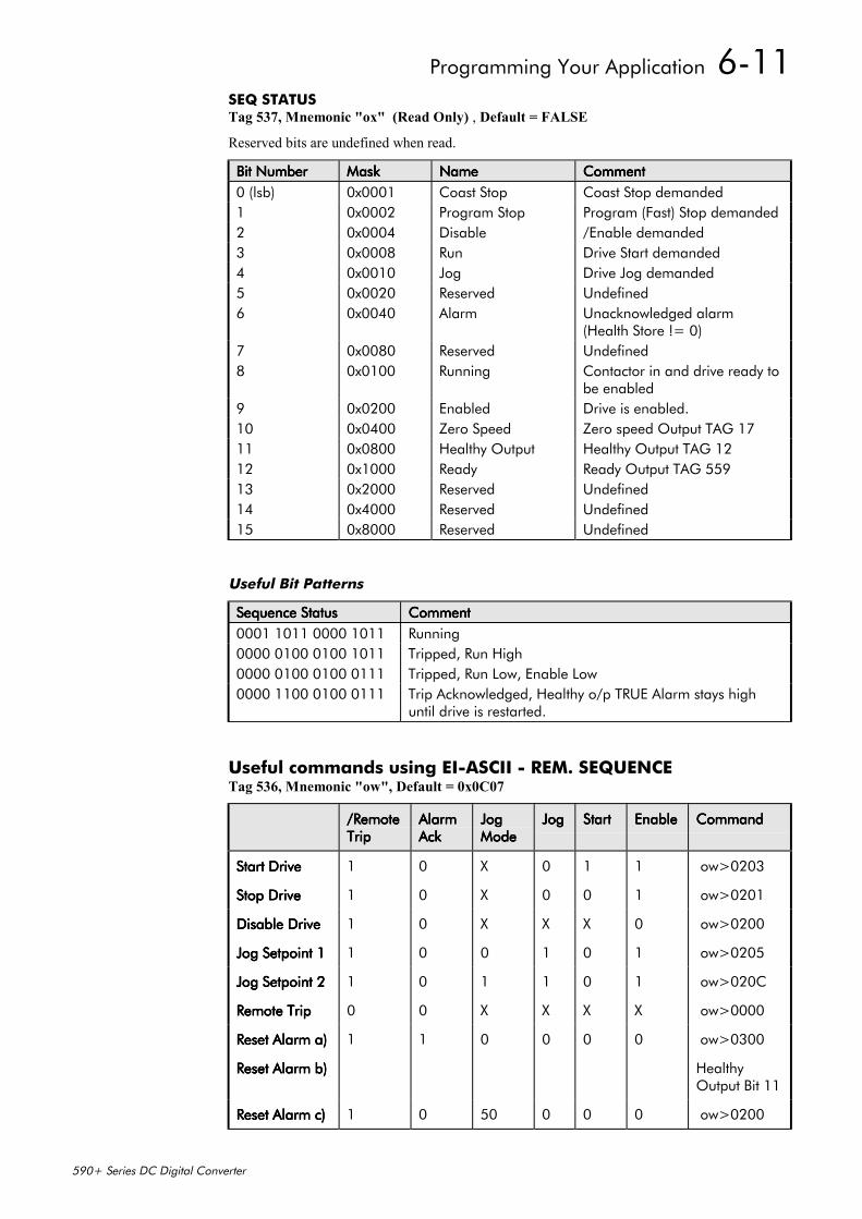
Programming Your Application 6-11
590+ Series DC Digital Converter
SEQ STATUSTag 537, Mnemonic "ox" (Read Only) , Default = FALSE
Reserved bits are undefined when read.
Bit NumberBit NumberBit NumberBit Number MaskMaskMaskMask NameNameNameName CommentCommentCommentComment0 (lsb) 0x0001 Coast Stop Coast Stop demanded1 0x0002 Program Stop Program (Fast) Stop demanded2 0x0004 Disable /Enable demanded3 0x0008 Run Drive Start demanded4 0x0010 Jog Drive Jog demanded5 0x0020 Reserved Undefined6 0x0040 Alarm Unacknowledged alarm
(Health Store != 0)7 0x0080 Reserved Undefined8 0x0100 Running Contactor in and drive ready to
be enabled9 0x0200 Enabled Drive is enabled.10 0x0400 Zero Speed Zero speed Output TAG 1711 0x0800 Healthy Output Healthy Output TAG 1212 0x1000 Ready Ready Output TAG 55913 0x2000 Reserved Undefined14 0x4000 Reserved Undefined15 0x8000 Reserved Undefined
Useful Bit Patterns
Sequence StatusSequence StatusSequence StatusSequence Status CommentCommentCommentComment0001 1011 0000 1011 Running0000 0100 0100 1011 Tripped, Run High0000 0100 0100 0111 Tripped, Run Low, Enable Low0000 1100 0100 0111 Trip Acknowledged, Healthy o/p TRUE Alarm stays high
until drive is restarted.
Useful commands using EI-ASCII - REM. SEQUENCETag 536, Mnemonic "ow", Default = 0x0C07
/Remote/Remote/Remote/RemoteTripTripTripTrip
AlarmAlarmAlarmAlarmAckAckAckAck
JogJogJogJogModeModeModeMode
JogJogJogJog StartStartStartStart EnableEnableEnableEnable CommandCommandCommandCommand
Start DriveStart DriveStart DriveStart Drive 1 0 X 0 1 1 ow>0203
Stop DriveStop DriveStop DriveStop Drive 1 0 X 0 0 1 ow>0201
Disable DriveDisable DriveDisable DriveDisable Drive 1 0 X X X 0 ow>0200
Jog Setpoint 1Jog Setpoint 1Jog Setpoint 1Jog Setpoint 1 1 0 0 1 0 1 ow>0205
Jog Setpoint 2Jog Setpoint 2Jog Setpoint 2Jog Setpoint 2 1 0 1 1 0 1 ow>020C
Remote TripRemote TripRemote TripRemote Trip 0 0 X X X X ow>0000
Reset Alarm a)Reset Alarm a)Reset Alarm a)Reset Alarm a) 1 1 0 0 0 0 ow>0300
Reset Alarm b)Reset Alarm b)Reset Alarm b)Reset Alarm b) HealthyOutput Bit 11
Reset Alarm c)Reset Alarm c)Reset Alarm c)Reset Alarm c) 1 0 50 0 0 0 ow>0200
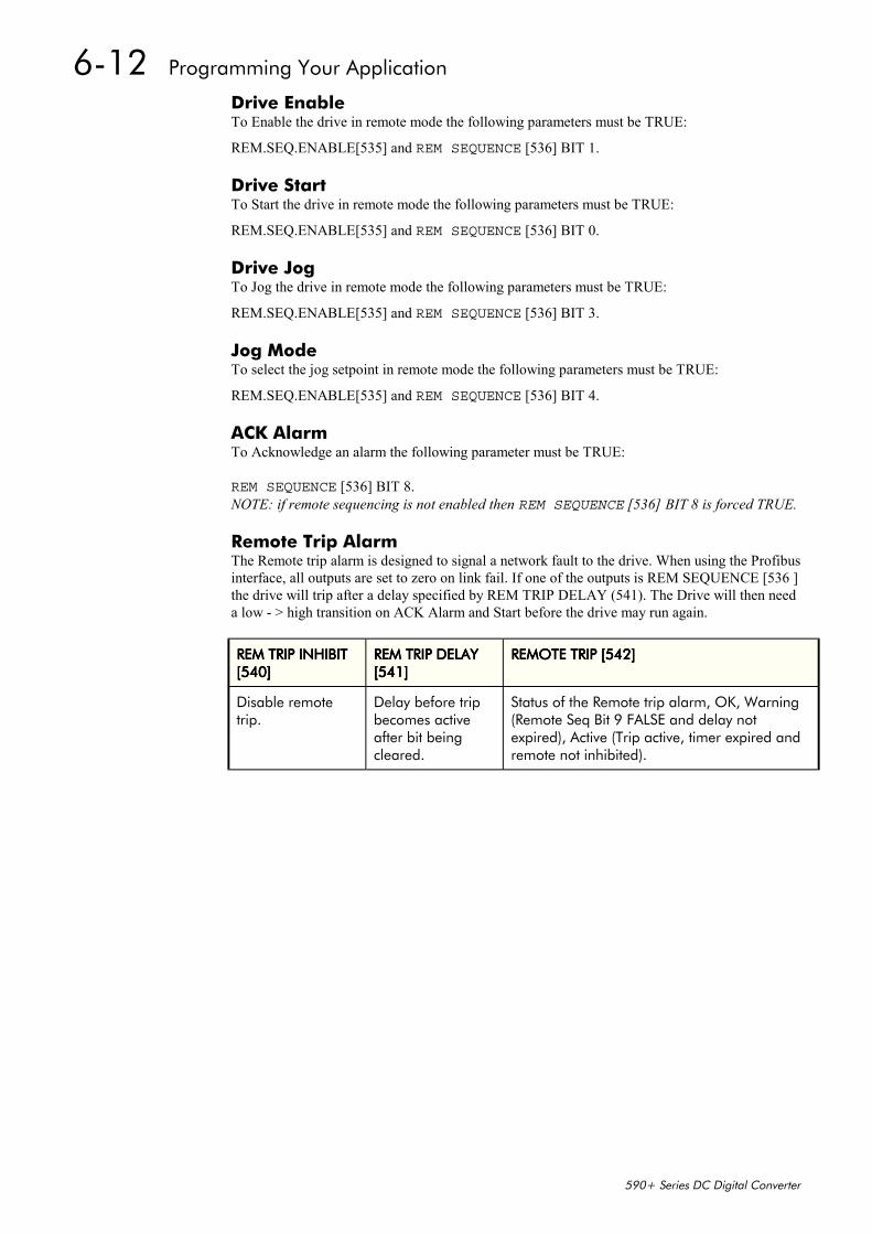
6-12 Programming Your Application
590+ Series DC Digital Converter
Drive EnableTo Enable the drive in remote mode the following parameters must be TRUE:
REM.SEQ.ENABLE[535] and REM SEQUENCE [536] BIT 1.
Drive StartTo Start the drive in remote mode the following parameters must be TRUE:
REM.SEQ.ENABLE[535] and REM SEQUENCE [536] BIT 0.
Drive JogTo Jog the drive in remote mode the following parameters must be TRUE:
REM.SEQ.ENABLE[535] and REM SEQUENCE [536] BIT 3.
Jog ModeTo select the jog setpoint in remote mode the following parameters must be TRUE:
REM.SEQ.ENABLE[535] and REM SEQUENCE [536] BIT 4.
ACK AlarmTo Acknowledge an alarm the following parameter must be TRUE:
REM SEQUENCE [536] BIT 8.NOTE: if remote sequencing is not enabled then REM SEQUENCE [536] BIT 8 is forced TRUE.
Remote Trip AlarmThe Remote trip alarm is designed to signal a network fault to the drive. When using the Profibusinterface, all outputs are set to zero on link fail. If one of the outputs is REM SEQUENCE [536 ]the drive will trip after a delay specified by REM TRIP DELAY (541). The Drive will then needa low - > high transition on ACK Alarm and Start before the drive may run again.
REM TRIP INHIBITREM TRIP INHIBITREM TRIP INHIBITREM TRIP INHIBIT[540][540][540][540]
REM TRIP DELAYREM TRIP DELAYREM TRIP DELAYREM TRIP DELAY[541][541][541][541]
REMOTE TRIP [542]REMOTE TRIP [542]REMOTE TRIP [542]REMOTE TRIP [542]
Disable remotetrip.
Delay before tripbecomes activeafter bit beingcleared.
Status of the Remote trip alarm, OK, Warning(Remote Seq Bit 9 FALSE and delay notexpired), Active (Trip active, timer expired andremote not inhibited).
Programming Your Application 6-13
590+ Series DC Digital Converter
BLOCK DIAGRAM (MMI only)The parameters in Block Diagram connect the outputs of RAISE/LOWER, RAMPS, SETPOINTSUM 1, and the Special Blocks (MMI menu) functions to destinations as required. Thesefunctions are only executed when the destinations are connected to a non-zero tag. If a function isnot required, set its destination tag to zero. This causes the processor to ignore the function andreduces processor loading.
MMI Menu Map 1 SYSTEM
2 CONFIGURE I/O
3 BLOCK DIAGRAM
RAISE/LOWER DESTRAMP O/P DESTSPT SUM 1 DESTPID O/P DESTDIAMETERTAPERSETPOINT SUM 2POS. I CLAMPNEG. I CLAMPTENS+COMP CALC.
Parameter DescriptionsRAISE/LOWER DEST Range: 0 to 549Refer to RAISE/LOWER, page 6-50.
RAMP O/P DEST Range: 0 to 549Refer to RAMPS, page 6-52.
SPT SUM 1 DEST Range: 0 to 549Refer to SETPOINT SUM 1, page 6-56.
PID O/P DEST Range: 0 to 549Refer to PID, page 6-47.
DIAMETER Range: 0 to 549Refer to DIAMETER CALC., page 6-27.
TAPER Range: 0 to 549Refer to Error! Not a valid result for table., page 6-72.
SETPOINT SUM 2 Range: 0 to 549Refer to SETPOINT SUM 2, page 6-57.
POS. I CLAMP Range: 0 to 549Refer to CURRENT LOOP, page 6-18.
NEG. I CLAMP Range: 0 to 549Refer to CURRENT LOOP, page 6-18.
TENS+COMP CALC. Range: 0 to 549Refer to TENS+COMP CALC., page 6-71.
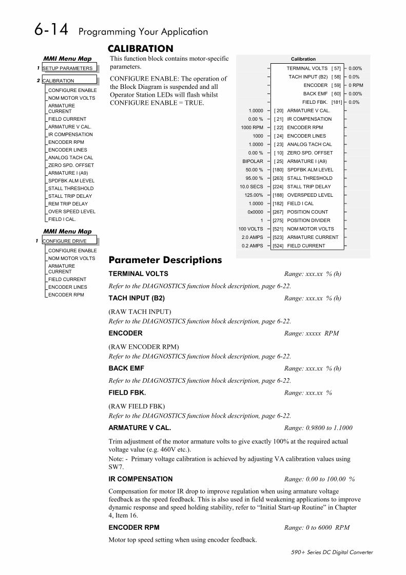
6-14 Programming Your Application
590+ Series DC Digital Converter
CALIBRATIONThis function block contains motor-specificparameters.
CONFIGURE ENABLE: The operation ofthe Block Diagram is suspended and allOperator Station LEDs will flash whilstCONFIGURE ENABLE = TRUE.
MMI Menu Map 1 SETUP PARAMETERS
2 CALIBRATION
CONFIGURE ENABLENOM MOTOR VOLTSARMATURECURRENTFIELD CURRENTARMATURE V CAL.IR COMPENSATIONENCODER RPMENCODER LINESANALOG TACH CALZERO SPD. OFFSETARMATURE I (A9)SPDFBK ALM LEVELSTALL THRESHOLDSTALL TRIP DELAYREM TRIP DELAYOVER SPEED LEVELFIELD I CAL.
Calibration
– TERMINAL VOLTS [ 57] – 0.00%– TACH INPUT (B2) [ 58] – 0.0%– ENCODER [ 59] – 0 RPM– BACK EMF [ 60] – 0.00%– FIELD FBK. [181] – 0.0%
1.0000 – [ 20] ARMATURE V CAL. –
0.00 % – [ 21] IR COMPENSATION –
1000 RPM – [ 22] ENCODER RPM –
1000 – [ 24] ENCODER LINES –
1.0000 – [ 23] ANALOG TACH CAL –
0.00 % – [ 10] ZERO SPD. OFFSET –
BIPOLAR – [ 25] ARMATURE I (A9) –
50.00 % – [180] SPDFBK ALM LEVEL –
95.00 % – [263] STALL THRESHOLD –
10.0 SECS – [224] STALL TRIP DELAY –
125.00% – [188] OVERSPEED LEVEL –
1.0000 – [182] FIELD I CAL –
0x0000 – [267] POSITION COUNT –
1 – [275] POSITION DIVIDER –
100 VOLTS – [521] NOM MOTOR VOLTS –
2.0 AMPS – [523] ARMATURE CURRENT –
0.2 AMPS – [524] FIELD CURRENT –
MMI Menu Map1 CONFIGURE DRIVE
CONFIGURE ENABLENOM MOTOR VOLTSARMATURECURRENTFIELD CURRENTENCODER LINESENCODER RPM
Parameter DescriptionsTERMINAL VOLTS Range: xxx.xx % (h)
Refer to the DIAGNOSTICS function block description, page 6-22.
TACH INPUT (B2) Range: xxx.xx % (h)
(RAW TACH INPUT)Refer to the DIAGNOSTICS function block description, page 6-22.
ENCODER Range: xxxxx RPM
(RAW ENCODER RPM)Refer to the DIAGNOSTICS function block description, page 6-22.
BACK EMF Range: xxx.xx % (h)
Refer to the DIAGNOSTICS function block description, page 6-22.
FIELD FBK. Range: xxx.xx %
(RAW FIELD FBK)Refer to the DIAGNOSTICS function block description, page 6-22.
ARMATURE V CAL. Range: 0.9800 to 1.1000
Trim adjustment of the motor armature volts to give exactly 100% at the required actualvoltage value (e.g. 460V etc.).Note: - Primary voltage calibration is achieved by adjusting VA calibration values usingSW7.
IR COMPENSATION Range: 0.00 to 100.00 %
Compensation for motor IR drop to improve regulation when using armature voltagefeedback as the speed feedback. This is also used in field weakening applications to improvedynamic response and speed holding stability, refer to “Initial Start-up Routine” in Chapter4, Item 16.
ENCODER RPM Range: 0 to 6000 RPM
Motor top speed setting when using encoder feedback.
Programming Your Application 6-15
590+ Series DC Digital Converter
ENCODER LINES Range: 10 to 5000The 5901 Microtach has 1000 lines per revolution as standard. Proprietary encoders of otherspecifications can be normalised by setting this parameter as appropriate.ANALOG TACH CAL Range: 0.9800 to 1.1000Trim adjustment of the motor speed to give exactly 100% at the required actual speed value(e.g. 1500 RPM etc). Note: Primary tacho calibration is achieved by adjusting SW1 - 3 on thetacho calibration board.ZERO SPD. OFFSET Range: -5.00 to 5.00 %If the speed feedback is not zero when the drive is stationary (possibly due to hardware offsetsetc.) the setting of this parameter to the value of the offset will result in a zero reading fromthe speed feedback.ARMATURE I (A9) Range: See belowSelects operation of the current meter output (terminal A9), either bipolar or unipolar.
0 : UNIPOLAR1 : BIPOLAR
SPDFBK ALM LEVEL Range: 0.00 to 100.00 % (h)The speed feedback alarm compares speed feedback to armature voltage. The alarm level isthe threshold which the difference between the two signals should exceed for the alarm toactivate.STALL THRESHOLD Range: 0.00 to 200.00 %Stall comparator current feedback threshold level.STALL TRIP DELAY Range: 0.1 to 600.0 SECSStall comparator time-out delay before stall output becomes true.
STALL THRESHOLD
STALL TRIP DELAY
ComparatorCURRENT FEEDBACK
DELAY STALL TRIP
SPEED FEEDBACK > 0.25%V/F Mode
OVERSPEED LEVEL Range: 0.00 to 200.00 %(OVER SPEED LEVEL)Speed feedback level for overspeed alarmFIELD I CAL Range: 0.9800 to 1.1000(FIELD I CAL.)Trim adjustment of the motor field current to give exactly 100% at the required actual currentvalue (e.g. 1.5A etc.). Note: Primary field calibration is achieved by adjusting IF calibrationusing SW1 - 3.POSITION COUNT Range: 0x0000 to 0xFFFFReserved parameter for use by Eurotherm Drives.POSITION DIVIDER Range: 1 to 30000Reserved parameter for use by Eurotherm Drives.NOM MOTOR VOLTS Range: 100 to 875 VOLTSSets the 100% value for Armature Volts VA. Set this value to match the motor in use.ARMATURE CURRENT Range: 2.0 to 15.0 AMPSSets the 100% value for Armature Current IA. Set this value to match the motor in use.FIELD CURRENT Range: 0.2 to 5.0 AMPSSets the 100% value for Field Current IF. Set this value to match the motor in use.
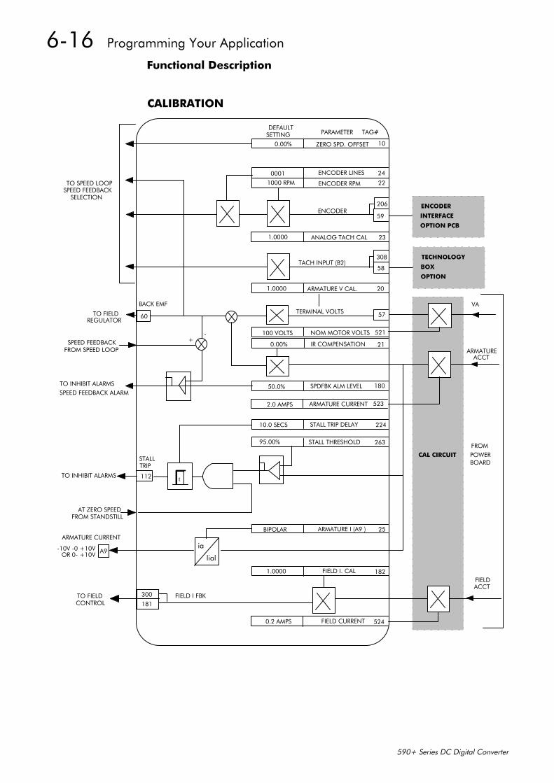
6-16 Programming Your Application
590+ Series DC Digital Converter
Functional Description
CALIBRATION
0.00% ZERO SPD. OFFSET
0001
1000 RPM
ENCODER LINES
ENCODER RPM
1.0000 ANALOG TACH CAL
1.0000 ARMATURE V CAL.
59
206ENCODER
308
58TACH INPUT (B2)
57TERMINAL VOLTS
0.00% IR COMPENSATION
10.0 SECS STALL TRIP DELAY
95.00% STALL THRESHOLD
BIPOLAR
1.0000
ARMATURE I (A9 )
FIELD I. CAL
ia
lial
112TO INHIBIT ALARMS
STALL TRIP
AT ZERO SPEED FROM STANDSTILL
DEFAULTSETTING PARAMETER TAG#
60
BACK EMF
TO SPEED LOOPSPEED FEEDBACK
SELECTION
300
181FIELD I FBKTO FIELD
ARMATURE CURRENT
-10V -0 +10V A9OR 0- +10V
TO INHIBIT ALARMSSPEED FEEDBACK ALARM
TO FIELDREGULATOR
SPEED FEEDBACKFROM SPEED LOOP
ENCODER
INTERFACE
OPTION PCB
VA
ARMATUREACCT
FIELDACCT
CAL CIRCUIT
10
24
22
23
20
21
50.0% SPDFBK ALM LEVEL 180
224
263
t
CONTROL
182
25
FROMPOWERBOARD
+-
TECHNOLOGY
BOX
OPTION
0.2 AMPS FIELD CURRENT 524
2.0 AMPS ARMATURE CURRENT 523
100 VOLTS NOM MOTOR VOLTS 521
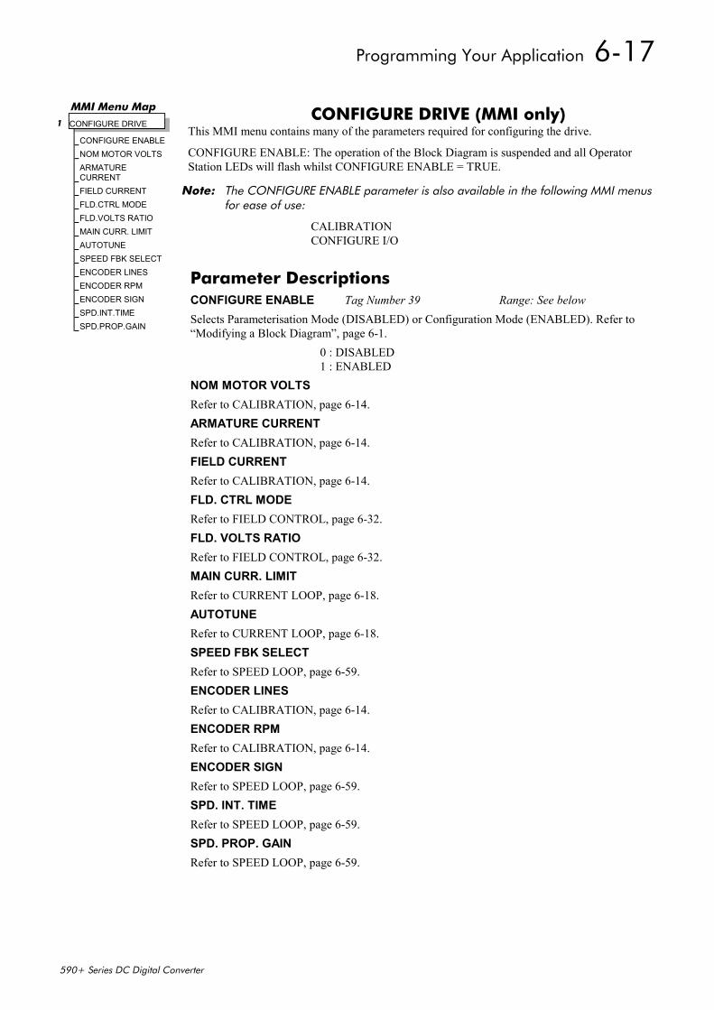
Programming Your Application 6-17
590+ Series DC Digital Converter
CONFIGURE DRIVE (MMI only)This MMI menu contains many of the parameters required for configuring the drive.
CONFIGURE ENABLE: The operation of the Block Diagram is suspended and all OperatorStation LEDs will flash whilst CONFIGURE ENABLE = TRUE.
Note: The CONFIGURE ENABLE parameter is also available in the following MMI menusfor ease of use:
CALIBRATIONCONFIGURE I/O
MMI Menu Map1 CONFIGURE DRIVE
CONFIGURE ENABLENOM MOTOR VOLTSARMATURECURRENTFIELD CURRENTFLD.CTRL MODEFLD.VOLTS RATIOMAIN CURR. LIMITAUTOTUNESPEED FBK SELECTENCODER LINESENCODER RPMENCODER SIGNSPD.INT.TIMESPD.PROP.GAIN
Parameter DescriptionsCONFIGURE ENABLE Tag Number 39 Range: See belowSelects Parameterisation Mode (DISABLED) or Configuration Mode (ENABLED). Refer to“Modifying a Block Diagram”, page 6-1.
0 : DISABLED1 : ENABLED
NOM MOTOR VOLTSRefer to CALIBRATION, page 6-14.ARMATURE CURRENTRefer to CALIBRATION, page 6-14.FIELD CURRENTRefer to CALIBRATION, page 6-14.FLD. CTRL MODERefer to FIELD CONTROL, page 6-32.FLD. VOLTS RATIORefer to FIELD CONTROL, page 6-32.MAIN CURR. LIMITRefer to CURRENT LOOP, page 6-18.AUTOTUNERefer to CURRENT LOOP, page 6-18.SPEED FBK SELECTRefer to SPEED LOOP, page 6-59.ENCODER LINESRefer to CALIBRATION, page 6-14.ENCODER RPMRefer to CALIBRATION, page 6-14.ENCODER SIGNRefer to SPEED LOOP, page 6-59.SPD. INT. TIMERefer to SPEED LOOP, page 6-59.SPD. PROP. GAINRefer to SPEED LOOP, page 6-59.
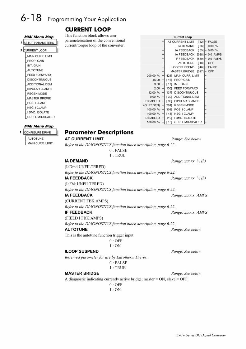
6-18 Programming Your Application
590+ Series DC Digital Converter
CURRENT LOOPThis function block allows userparameterisation of the conventionalcurrent/torque loop of the converter.
Current Loop– AT CURRENT LIMIT [ 42] – FALSE– IA DEMAND [ 66] – 0.00 %– IA FEEDBACK [ 65] – 0.00 %– IA FEEDBACK [538] – 0.0 AMPS– IF FEEDBACK [539] – 0.0 AMPS– AUTOTUNE [ 18] – OFF– ILOOP SUSPEND [ 46] – FALSE– MASTER BRIDGE [527] – OFF
200.00 % – [421] MAIN CURR. LIMIT –45.00 – [ 16] PROP GAIN –3.50 – [ 17] INT. GAIN –2.00 – [136] FEED FORWARD –
12.00 % – [137] DISCONTINUOUS –0.00 % – [ 30] ADDITIONAL DEM –
DISABLED – [ 90] BIPOLAR CLAMPS –4Q (REGEN) – [201] REGEN MODE –
100.00 % – [301] POS. I CLAMP –-100.00 % – [ 48] NEG. I CLAMP –DISABLED – [119] I DMD. ISOLATE –100.00 % – [ 15] CUR. LIMIT/SCALER –
MMI Menu Map 1 SETUP PARAMETERS
2 CURRENT LOOP
MAIN CURR. LIMITPROP. GAININT. GAINAUTOTUNEFEED FORWARDDISCONTINUOUSADDITIONAL DEMBIPOLAR CLAMPSREGEN MODEMASTER BRIDGEPOS. I CLAMPNEG. I CLAMPI DMD. ISOLATECUR. LIMIT/SCALER
MMI Menu Map
1 CONFIGURE DRIVE
AUTOTUNEMAIN CURR. LIMIT
Parameter DescriptionsAT CURRENT LIMIT Range: See belowRefer to the DIAGNOSTICS function block description, page 6-22.
0 : FALSE1 : TRUE
IA DEMAND Range: xxx.xx % (h)(IaDmd UNFILTERED)Refer to the DIAGNOSTICS function block description, page 6-22.IA FEEDBACK Range: xxx.xx % (h)(IaFbk UNFILTERED)Refer to the DIAGNOSTICS function block description, page 6-22.IA FEEDBACK Range: xxxx.x AMPS(CURRENT FBK.AMPS)Refer to the DIAGNOSTICS function block description, page 6-22.IF FEEDBACK Range: xxxx.x AMPS(FIELD I FBK.AMPS)Refer to the DIAGNOSTICS function block description, page 6-22.AUTOTUNE Range: See belowThis is the autotune function trigger input.
0 : OFF1 : ON
ILOOP SUSPEND Range: See belowReserved parameter for use by Eurotherm Drives.
0 : FALSE1 : TRUE
MASTER BRIDGE Range: See belowA diagnostic indicating currently active bridge; master = ON, slave = OFF.
0 : OFF1 : ON
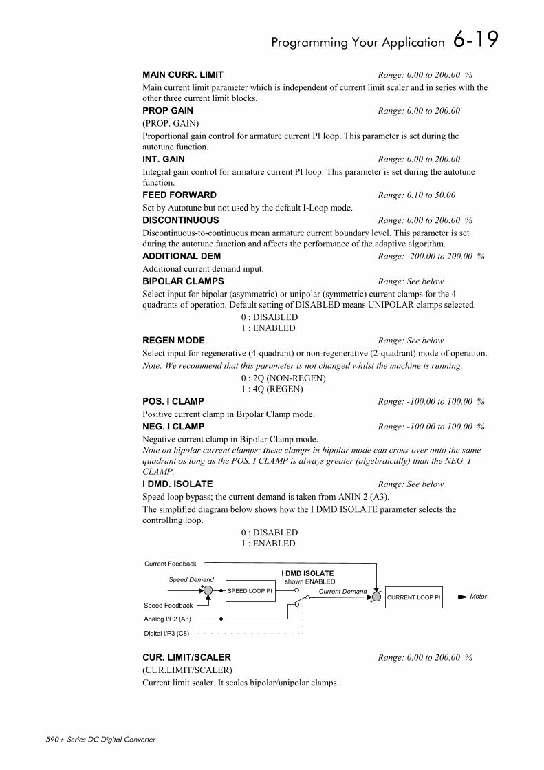
Programming Your Application 6-19
590+ Series DC Digital Converter
MAIN CURR. LIMIT Range: 0.00 to 200.00 %Main current limit parameter which is independent of current limit scaler and in series with theother three current limit blocks.PROP GAIN Range: 0.00 to 200.00(PROP. GAIN)Proportional gain control for armature current PI loop. This parameter is set during theautotune function.INT. GAIN Range: 0.00 to 200.00Integral gain control for armature current PI loop. This parameter is set during the autotunefunction.FEED FORWARD Range: 0.10 to 50.00Set by Autotune but not used by the default I-Loop mode.DISCONTINUOUS Range: 0.00 to 200.00 %Discontinuous-to-continuous mean armature current boundary level. This parameter is setduring the autotune function and affects the performance of the adaptive algorithm.ADDITIONAL DEM Range: -200.00 to 200.00 %Additional current demand input.BIPOLAR CLAMPS Range: See belowSelect input for bipolar (asymmetric) or unipolar (symmetric) current clamps for the 4quadrants of operation. Default setting of DISABLED means UNIPOLAR clamps selected.
0 : DISABLED1 : ENABLED
REGEN MODE Range: See belowSelect input for regenerative (4-quadrant) or non-regenerative (2-quadrant) mode of operation.Note: We recommend that this parameter is not changed whilst the machine is running.
0 : 2Q (NON-REGEN)1 : 4Q (REGEN)
POS. I CLAMP Range: -100.00 to 100.00 %Positive current clamp in Bipolar Clamp mode.NEG. I CLAMP Range: -100.00 to 100.00 %Negative current clamp in Bipolar Clamp mode.Note on bipolar current clamps: these clamps in bipolar mode can cross-over onto the samequadrant as long as the POS. I CLAMP is always greater (algebraically) than the NEG. ICLAMP.I DMD. ISOLATE Range: See belowSpeed loop bypass; the current demand is taken from ANIN 2 (A3).The simplified diagram below shows how the I DMD ISOLATE parameter selects thecontrolling loop.
0 : DISABLED1 : ENABLED
SPEED LOOP PICURRENT LOOP PI
Speed Demand
Speed Feedback
Analog I/P2 (A3)
Digital I/P3 (C8)
I DMD ISOLATE
Current Demand
Current Feedback
Motor
shown ENABLED+
-+
-
CUR. LIMIT/SCALER Range: 0.00 to 200.00 %(CUR.LIMIT/SCALER)Current limit scaler. It scales bipolar/unipolar clamps.
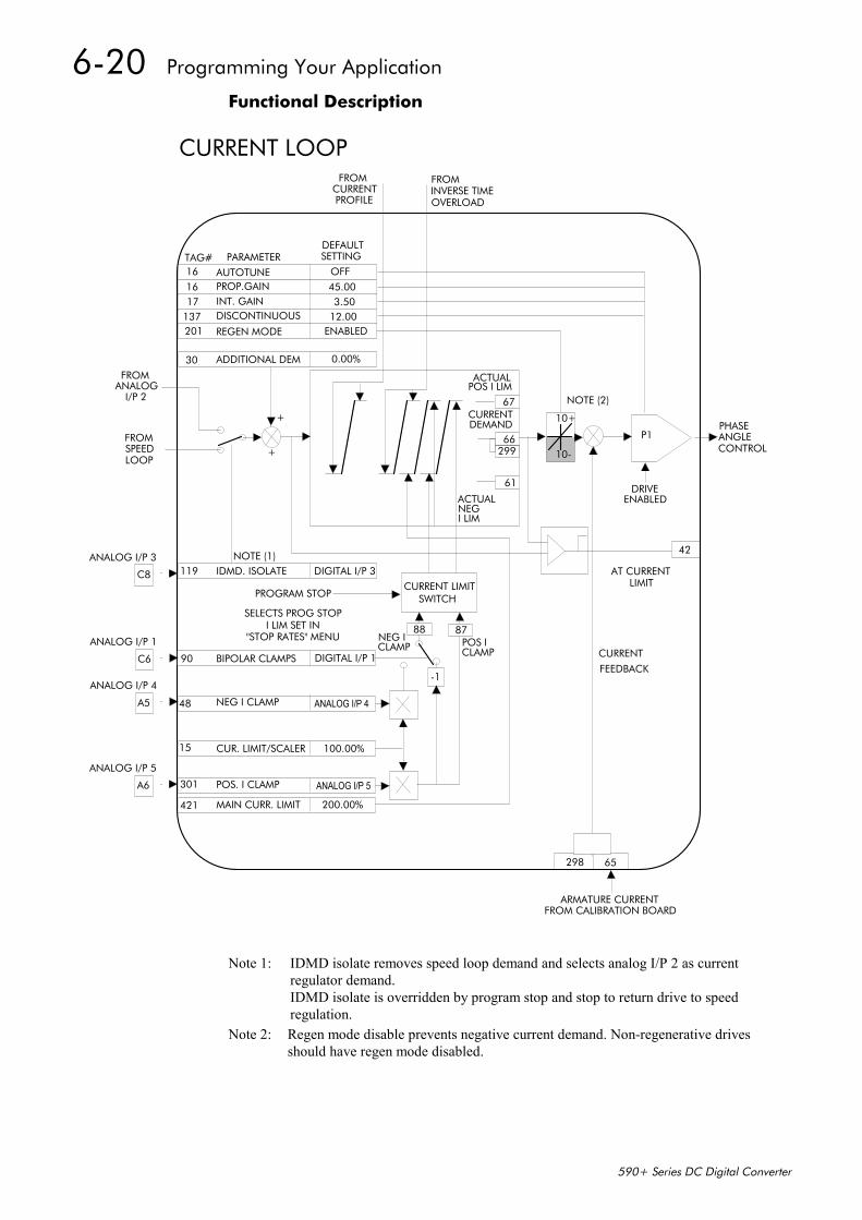
6-20 Programming Your Application
590+ Series DC Digital Converter
Functional Description
TAG# PARAMETERDEFAULTSETTING
137 DISCONTINUOUS
161617
201
AUTOTUNEPROP.GAININT. GAIN
REGEN MODE
OFF45.003.50
12.00ENABLED
30 ADDITIONAL DEM 0.00%
10+
10-299
67
66
61
ACTUALPOS I LIM
CURRENTDEMAND
ACTUALNEGI LIM
NOTE (1)119 IDMD. ISOLATE DIGITAL I/P 3
CURRENT LIMITSWITCHPROGRAM STOP
SELECTS PROG STOPI LIM SET IN
"STOP RATES" MENU
90 BIPOLAR CLAMPS DIGITAL I/P 1
48 NEG I CLAMP ANALOG I/P 4
15 CUR. LIMIT/SCALER 100.00%
301 POS. I CLAMP ANALOG I/P 5
421 MAIN CURR. LIMIT 200.00%
-1
88 87NEG ICLAMP POS I
CLAMP
+
+
DRIVEENABLED
P1PHASEANGLECONTROL
42
AT CURRENTLIMIT
CURRENT
FEEDBACK
298 65
ARMATURE CURRENTFROM CALIBRATION BOARD
A6
ANALOG I/P 5
A5
ANALOG I/P 4
C6
ANALOG I/P 1
C8
ANALOG I/P 3
FROMANALOG
I/P 2
FROMSPEEDLOOP
CURRENT LOOPFROM
CURRENTPROFILE
FROMINVERSE TIMEOVERLOAD
NOTE (2)
Note 1: IDMD isolate removes speed loop demand and selects analog I/P 2 as currentregulator demand.IDMD isolate is overridden by program stop and stop to return drive to speedregulation.
Note 2: Regen mode disable prevents negative current demand. Non-regenerative drivesshould have regen mode disabled.
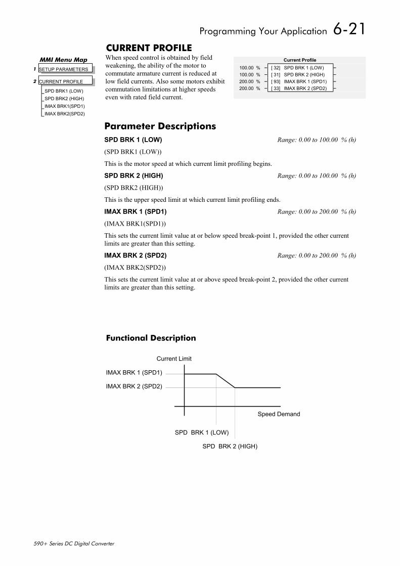
Programming Your Application 6-21
590+ Series DC Digital Converter
CURRENT PROFILEWhen speed control is obtained by fieldweakening, the ability of the motor tocommutate armature current is reduced atlow field currents. Also some motors exhibitcommutation limitations at higher speedseven with rated field current.
Functional Description
IMAX BRK 1 (SPD1)
IMAX BRK 2 (SPD2)
SPD BRK 1 (LOW)
SPD BRK 2 (HIGH)
Current Limit
Speed Demand
MMI Menu Map 1 SETUP PARAMETERS
2 CURRENT PROFILE
SPD BRK1 (LOW)SPD BRK2 (HIGH)IMAX BRK1(SPD1)IMAX BRK2(SPD2)
Current Profile100.00 % – [ 32] SPD BRK 1 (LOW) –100.00 % – [ 31] SPD BRK 2 (HIGH) –200.00 % – [ 93] IMAX BRK 1 (SPD1) –200.00 % – [ 33] IMAX BRK 2 (SPD2) –
Parameter DescriptionsSPD BRK 1 (LOW) Range: 0.00 to 100.00 % (h)
(SPD BRK1 (LOW))
This is the motor speed at which current limit profiling begins.
SPD BRK 2 (HIGH) Range: 0.00 to 100.00 % (h)
(SPD BRK2 (HIGH))
This is the upper speed limit at which current limit profiling ends.
IMAX BRK 1 (SPD1) Range: 0.00 to 200.00 % (h)
(IMAX BRK1(SPD1))
This sets the current limit value at or below speed break-point 1, provided the other currentlimits are greater than this setting.
IMAX BRK 2 (SPD2) Range: 0.00 to 200.00 % (h)
(IMAX BRK2(SPD2))
This sets the current limit value at or above speed break-point 2, provided the other currentlimits are greater than this setting.
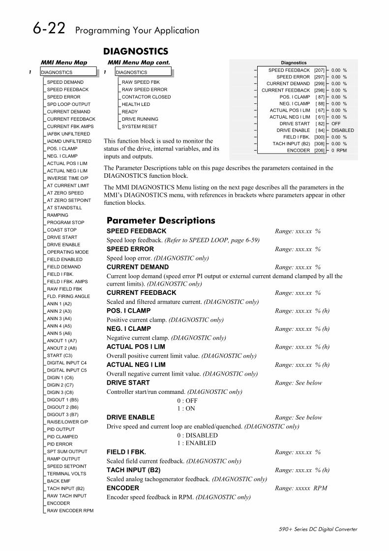
6-22 Programming Your Application
590+ Series DC Digital Converter
DIAGNOSTICS
This function block is used to monitor thestatus of the drive, internal variables, and itsinputs and outputs.
The Parameter Descriptions table on this page describes the parameters contained in theDIAGNOSTICS function block.
The MMI DIAGNOSTICS Menu listing on the next page describes all the parameters in theMMI’s DIAGNOSTICS menu, with references in brackets where parameters appear in otherfunction blocks.
MMI Menu Map
1 DIAGNOSTICS
SPEED DEMANDSPEED FEEDBACKSPEED ERRORSPD LOOP OUTPUTCURRENT DEMANDCURRENT FEEDBACKCURRENT FBK AMPSIAFBK UNFILTEREDIADMD UNFILTEREDPOS. I CLAMPNEG. I CLAMPACTUAL POS I LIMACTUAL NEG I LIMINVERSE TIME O/PAT CURRENT LIMITAT ZERO SPEEDAT ZERO SETPOINTAT STANDSTILLRAMPINGPROGRAM STOPCOAST STOPDRIVE STARTDRIVE ENABLEOPERATING MODEFIELD ENABLEDFIELD DEMANDFIELD I FBK.FIELD I FBK. AMPSRAW FIELD FBKFLD. FIRING ANGLEANIN 1 (A2)ANIN 2 (A3)ANIN 3 (A4)ANIN 4 (A5)ANIN 5 (A6)ANOUT 1 (A7)ANOUT 2 (A8)START (C3)DIGITAL INPUT C4DIGITAL INPUT C5DIGIN 1 (C6)DIGIN 2 (C7)DIGIN 3 (C8)DIGOUT 1 (B5)DIGOUT 2 (B6)DIGOUT 3 (B7)RAISE/LOWER O/PPID OUTPUTPID CLAMPEDPID ERRORSPT SUM OUTPUTRAMP OUTPUTSPEED SETPOINTTERMINAL VOLTSBACK EMFTACH INPUT (B2)RAW TACH INPUTENCODERRAW ENCODER RPM
Diagnostics– SPEED FEEDBACK [207] – 0.00 %– SPEED ERROR [297] – 0.00 %– CURRENT DEMAND [299] – 0.00 %– CURRENT FEEDBACK [298] – 0.00 %– POS. I CLAMP [ 87] – 0.00 %– NEG. I CLAMP [ 88] – 0.00 %– ACTUAL POS I LIM [ 67] – 0.00 %– ACTUAL NEG I LIM [ 61] – 0.00 %– DRIVE START [ 82] – OFF– DRIVE ENABLE [ 84] – DISABLED– FIELD I FBK. [300] – 0.00 %– TACH INPUT (B2) [308] – 0.00 %– ENCODER [206] – 0 RPM
MMI Menu Map cont.
1 DIAGNOSTICS
RAW SPEED FBKRAW SPEED ERRORCONTACTOR CLOSEDHEALTH LEDREADYDRIVE RUNNINGSYSTEM RESET
Parameter DescriptionsSPEED FEEDBACK Range: xxx.xx %Speed loop feedback. (Refer to SPEED LOOP, page 6-59)SPEED ERROR Range: xxx.xx %Speed loop error. (DIAGNOSTIC only)CURRENT DEMAND Range: xxx.xx %Current loop demand (speed error PI output or external current demand clamped by all thecurrent limits). (DIAGNOSTIC only)CURRENT FEEDBACK Range: xxx.xx %Scaled and filtered armature current. (DIAGNOSTIC only)POS. I CLAMP Range: xxx.xx % (h)Positive current clamp. (DIAGNOSTIC only)NEG. I CLAMP Range: xxx.xx % (h)Negative current clamp. (DIAGNOSTIC only)ACTUAL POS I LIM Range: xxx.xx % (h)Overall positive current limit value. (DIAGNOSTIC only)ACTUAL NEG I LIM Range: xxx.xx % (h)Overall negative current limit value. (DIAGNOSTIC only)DRIVE START Range: See belowController start/run command. (DIAGNOSTIC only)
0 : OFF1 : ON
DRIVE ENABLE Range: See belowDrive speed and current loop are enabled/quenched. (DIAGNOSTIC only)
0 : DISABLED1 : ENABLED
FIELD I FBK. Range: xxx.xx %Scaled field current feedback. (DIAGNOSTIC only)TACH INPUT (B2) Range: xxx.xx % (h)Scaled analog tachogenerator feedback. (DIAGNOSTIC only)ENCODER Range: xxxxx RPMEncoder speed feedback in RPM. (DIAGNOSTIC only)
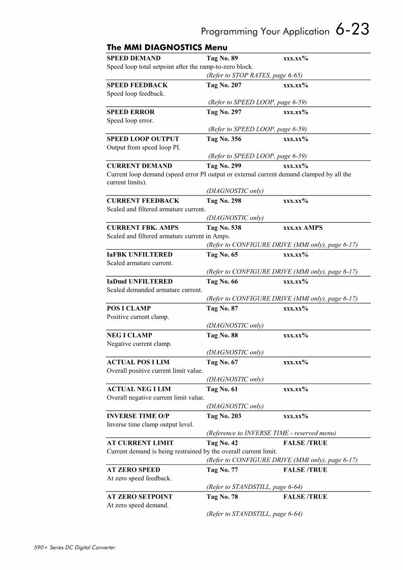
Programming Your Application 6-23
590+ Series DC Digital Converter
The MMI DIAGNOSTICS MenuSPEED DEMAND Tag No. 89 xxx.xx%Speed loop total setpoint after the ramp-to-zero block.
(Refer to STOP RATES, page 6-65)SPEED FEEDBACK Tag No. 207 xxx.xx%Speed loop feedback.
(Refer to SPEED LOOP, page 6-59)SPEED ERROR Tag No. 297 xxx.xx%Speed loop error.
(Refer to SPEED LOOP, page 6-59)SPEED LOOP OUTPUT Tag No. 356 xxx.xx%Output from speed loop PI.
(Refer to SPEED LOOP, page 6-59)CURRENT DEMAND Tag No. 299 xxx.xx%Current loop demand (speed error PI output or external current demand clamped by all thecurrent limits).
(DIAGNOSTIC only)CURRENT FEEDBACK Tag No. 298 xxx.xx%Scaled and filtered armature current.
(DIAGNOSTIC only)CURRENT FBK. AMPS Tag No. 538 xxx.xx AMPSScaled and filtered armature current in Amps.
(Refer to CONFIGURE DRIVE (MMI only), page 6-17)IaFBK UNFILTERED Tag No. 65 xxx.xx%Scaled armature current.
(Refer to CONFIGURE DRIVE (MMI only), page 6-17)IaDmd UNFILTERED Tag No. 66 xxx.xx%Scaled demanded armature current.
(Refer to CONFIGURE DRIVE (MMI only), page 6-17)POS I CLAMP Tag No. 87 xxx.xx%Positive current clamp.
(DIAGNOSTIC only)NEG I CLAMP Tag No. 88 xxx.xx%Negative current clamp.
(DIAGNOSTIC only)ACTUAL POS I LIM Tag No. 67 xxx.xx%Overall positive current limit value.
(DIAGNOSTIC only)ACTUAL NEG I LIM Tag No. 61 xxx.xx%Overall negative current limit value.
(DIAGNOSTIC only)INVERSE TIME O/P Tag No. 203 xxx.xx%Inverse time clamp output level.
(Reference to INVERSE TIME - reserved menu)AT CURRENT LIMIT Tag No. 42 FALSE /TRUECurrent demand is being restrained by the overall current limit.
(Refer to CONFIGURE DRIVE (MMI only), page 6-17)AT ZERO SPEED Tag No. 77 FALSE /TRUEAt zero speed feedback.
(Refer to STANDSTILL, page 6-64)AT ZERO SETPOINT Tag No. 78 FALSE /TRUEAt zero speed demand.
(Refer to STANDSTILL, page 6-64)
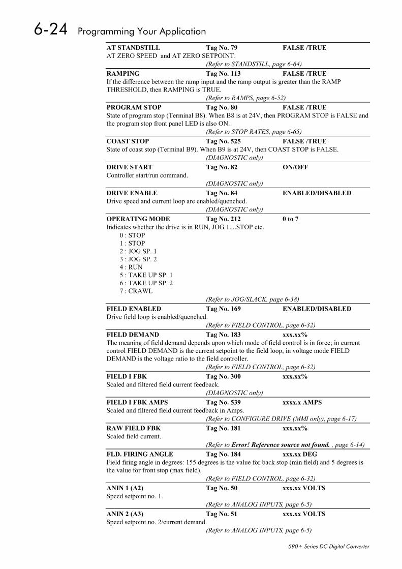
6-24 Programming Your Application
590+ Series DC Digital Converter
AT STANDSTILL Tag No. 79 FALSE /TRUEAT ZERO SPEED and AT ZERO SETPOINT.
(Refer to STANDSTILL, page 6-64)RAMPING Tag No. 113 FALSE /TRUEIf the difference between the ramp input and the ramp output is greater than the RAMPTHRESHOLD, then RAMPING is TRUE.
(Refer to RAMPS, page 6-52)PROGRAM STOP Tag No. 80 FALSE /TRUEState of program stop (Terminal B8). When B8 is at 24V, then PROGRAM STOP is FALSE andthe program stop front panel LED is also ON.
(Refer to STOP RATES, page 6-65)COAST STOP Tag No. 525 FALSE /TRUEState of coast stop (Terminal B9). When B9 is at 24V, then COAST STOP is FALSE.
(DIAGNOSTIC only)DRIVE START Tag No. 82 ON/OFFController start/run command.
(DIAGNOSTIC only)DRIVE ENABLE Tag No. 84 ENABLED/DISABLEDDrive speed and current loop are enabled/quenched.
(DIAGNOSTIC only)OPERATING MODE Tag No. 212 0 to 7Indicates whether the drive is in RUN, JOG 1....STOP etc.
0 : STOP1 : STOP2 : JOG SP. 13 : JOG SP. 24 : RUN5 : TAKE UP SP. 16 : TAKE UP SP. 27 : CRAWL
(Refer to JOG/SLACK, page 6-38)FIELD ENABLED Tag No. 169 ENABLED/DISABLEDDrive field loop is enabled/quenched.
(Refer to FIELD CONTROL, page 6-32)FIELD DEMAND Tag No. 183 xxx.xx%The meaning of field demand depends upon which mode of field control is in force; in currentcontrol FIELD DEMAND is the current setpoint to the field loop, in voltage mode FIELDDEMAND is the voltage ratio to the field controller.
(Refer to FIELD CONTROL, page 6-32)FIELD I FBK Tag No. 300 xxx.xx%Scaled and filtered field current feedback.
(DIAGNOSTIC only)FIELD I FBK AMPS Tag No. 539 xxxx.x AMPSScaled and filtered field current feedback in Amps.
(Refer to CONFIGURE DRIVE (MMI only), page 6-17)RAW FIELD FBK Tag No. 181 xxx.xx%Scaled field current.
(Refer to Error! Reference source not found. , page 6-14)FLD. FIRING ANGLE Tag No. 184 xxx.xx DEGField firing angle in degrees: 155 degrees is the value for back stop (min field) and 5 degrees isthe value for front stop (max field).
(Refer to FIELD CONTROL, page 6-32)ANIN 1 (A2) Tag No. 50 xxx.xx VOLTSSpeed setpoint no. 1.
(Refer to ANALOG INPUTS, page 6-5)ANIN 2 (A3) Tag No. 51 xxx.xx VOLTSSpeed setpoint no. 2/current demand.
(Refer to ANALOG INPUTS, page 6-5)
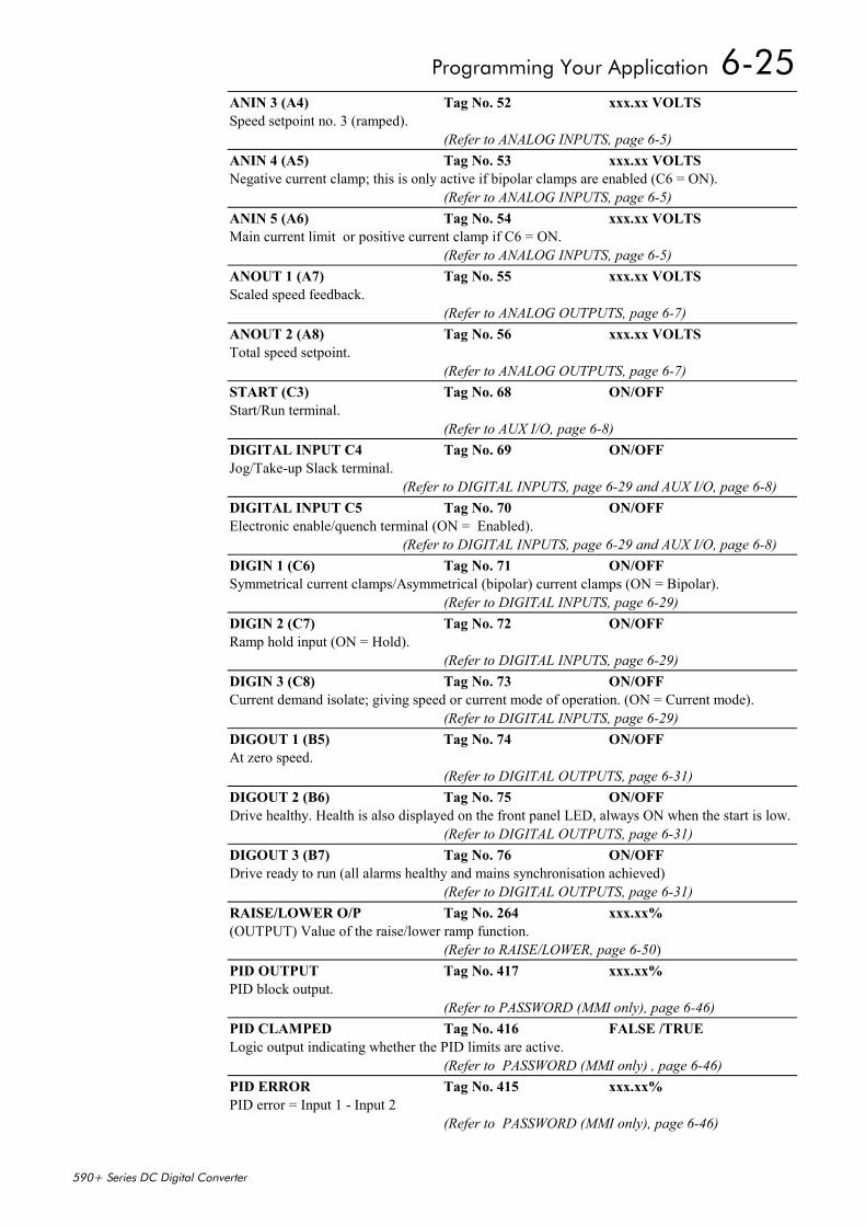
Programming Your Application 6-25
590+ Series DC Digital Converter
ANIN 3 (A4) Tag No. 52 xxx.xx VOLTSSpeed setpoint no. 3 (ramped).
(Refer to ANALOG INPUTS, page 6-5)ANIN 4 (A5) Tag No. 53 xxx.xx VOLTSNegative current clamp; this is only active if bipolar clamps are enabled (C6 = ON).
(Refer to ANALOG INPUTS, page 6-5)ANIN 5 (A6) Tag No. 54 xxx.xx VOLTSMain current limit or positive current clamp if C6 = ON.
(Refer to ANALOG INPUTS, page 6-5)ANOUT 1 (A7) Tag No. 55 xxx.xx VOLTSScaled speed feedback.
(Refer to ANALOG OUTPUTS, page 6-7)ANOUT 2 (A8) Tag No. 56 xxx.xx VOLTSTotal speed setpoint.
(Refer to ANALOG OUTPUTS, page 6-7)START (C3) Tag No. 68 ON/OFFStart/Run terminal.
(Refer to AUX I/O, page 6-8)DIGITAL INPUT C4 Tag No. 69 ON/OFFJog/Take-up Slack terminal.
(Refer to DIGITAL INPUTS, page 6-29 and AUX I/O, page 6-8)DIGITAL INPUT C5 Tag No. 70 ON/OFFElectronic enable/quench terminal (ON = Enabled).
(Refer to DIGITAL INPUTS, page 6-29 and AUX I/O, page 6-8)DIGIN 1 (C6) Tag No. 71 ON/OFFSymmetrical current clamps/Asymmetrical (bipolar) current clamps (ON = Bipolar).
(Refer to DIGITAL INPUTS, page 6-29)DIGIN 2 (C7) Tag No. 72 ON/OFFRamp hold input (ON = Hold).
(Refer to DIGITAL INPUTS, page 6-29)DIGIN 3 (C8) Tag No. 73 ON/OFFCurrent demand isolate; giving speed or current mode of operation. (ON = Current mode).
(Refer to DIGITAL INPUTS, page 6-29)DIGOUT 1 (B5) Tag No. 74 ON/OFFAt zero speed.
(Refer to DIGITAL OUTPUTS, page 6-31)DIGOUT 2 (B6) Tag No. 75 ON/OFFDrive healthy. Health is also displayed on the front panel LED, always ON when the start is low.
(Refer to DIGITAL OUTPUTS, page 6-31)DIGOUT 3 (B7) Tag No. 76 ON/OFFDrive ready to run (all alarms healthy and mains synchronisation achieved) (Refer to DIGITAL OUTPUTS, page 6-31)RAISE/LOWER O/P Tag No. 264 xxx.xx%(OUTPUT) Value of the raise/lower ramp function.
(Refer to RAISE/LOWER, page 6-50)PID OUTPUT Tag No. 417 xxx.xx%PID block output.
(Refer to PASSWORD (MMI only), page 6-46)PID CLAMPED Tag No. 416 FALSE /TRUELogic output indicating whether the PID limits are active.
(Refer to PASSWORD (MMI only) , page 6-46)PID ERROR Tag No. 415 xxx.xx%PID error = Input 1 - Input 2
(Refer to PASSWORD (MMI only), page 6-46)
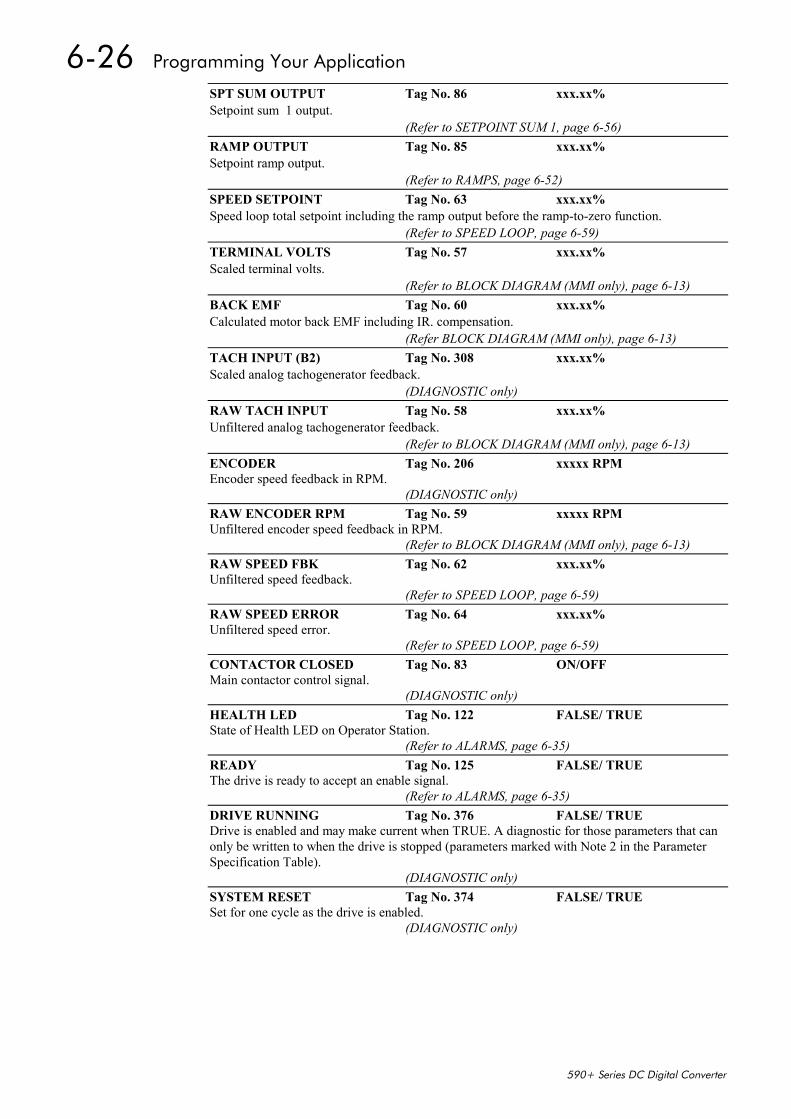
6-26 Programming Your Application
590+ Series DC Digital Converter
SPT SUM OUTPUT Tag No. 86 xxx.xx%Setpoint sum 1 output.
(Refer to SETPOINT SUM 1, page 6-56)RAMP OUTPUT Tag No. 85 xxx.xx%Setpoint ramp output.
(Refer to RAMPS, page 6-52)SPEED SETPOINT Tag No. 63 xxx.xx%Speed loop total setpoint including the ramp output before the ramp-to-zero function.
(Refer to SPEED LOOP, page 6-59)TERMINAL VOLTS Tag No. 57 xxx.xx%Scaled terminal volts.
(Refer to BLOCK DIAGRAM (MMI only), page 6-13)BACK EMF Tag No. 60 xxx.xx%Calculated motor back EMF including IR. compensation.
(Refer BLOCK DIAGRAM (MMI only), page 6-13)TACH INPUT (B2) Tag No. 308 xxx.xx%Scaled analog tachogenerator feedback.
(DIAGNOSTIC only)RAW TACH INPUT Tag No. 58 xxx.xx%Unfiltered analog tachogenerator feedback.
(Refer to BLOCK DIAGRAM (MMI only), page 6-13)ENCODER Tag No. 206 xxxxx RPMEncoder speed feedback in RPM.
(DIAGNOSTIC only)RAW ENCODER RPM Tag No. 59 xxxxx RPMUnfiltered encoder speed feedback in RPM.
(Refer to BLOCK DIAGRAM (MMI only), page 6-13)RAW SPEED FBK Tag No. 62 xxx.xx%Unfiltered speed feedback.
(Refer to SPEED LOOP, page 6-59)RAW SPEED ERROR Tag No. 64 xxx.xx%Unfiltered speed error.
(Refer to SPEED LOOP, page 6-59)CONTACTOR CLOSED Tag No. 83 ON/OFFMain contactor control signal.
(DIAGNOSTIC only)HEALTH LED Tag No. 122 FALSE/ TRUEState of Health LED on Operator Station.
(Refer to ALARMS, page 6-35)READY Tag No. 125 FALSE/ TRUEThe drive is ready to accept an enable signal.
(Refer to ALARMS, page 6-35)DRIVE RUNNING Tag No. 376 FALSE/ TRUEDrive is enabled and may make current when TRUE. A diagnostic for those parameters that canonly be written to when the drive is stopped (parameters marked with Note 2 in the ParameterSpecification Table).
(DIAGNOSTIC only)SYSTEM RESET Tag No. 374 FALSE/ TRUESet for one cycle as the drive is enabled.
(DIAGNOSTIC only)
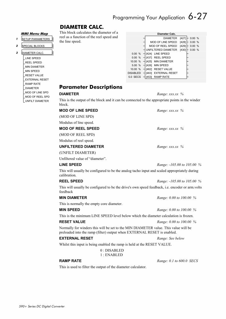
Programming Your Application 6-27
590+ Series DC Digital Converter
DIAMETER CALC.This block calculates the diameter of areel as a function of the reel speed andthe line speed.
MMI Menu Map 1 SETUP PARAMETERS
2 SPECIAL BLOCKS
3 DIAMETER CALC.
LINE SPEEDREEL SPEEDMIN DIAMETERMIN SPEEDRESET VALUEEXTERNAL RESETRAMP RATEDIAMETERMOD OF LINE SPDMOD OF REEL SPDUNFILT DIAMETER
Diameter Calc.– DIAMETER [427] – 0.00 %– MOD OF LINE SPEED [428] – 0.00 %– MOD OF REEL SPEED [429] – 0.00 %– UNFILTERED DIAMETER [430] – 0.00 %
0.00 % – [424] LINE SPEED –0.00 % – [437] REEL SPEED –
10.00 % – [425] MIN DIAMETER –5.00 % – [426] MIN SPEED –
10.00 % – [462] RESET VALUE –DISABLED – [463] EXTERNAL RESET –5.0 SECS – [453] RAMP RATE –
Parameter DescriptionsDIAMETER Range: xxx.xx %This is the output of the block and it can be connected to the appropriate points in the winderblock.MOD OF LINE SPEED Range: xxx.xx %(MOD OF LINE SPD)Modulus of line speed.MOD OF REEL SPEED Range: xxx.xx %(MOD OF REEL SPD)Modulus of reel speed.UNFILTERED DIAMETER Range: xxx.xx %(UNFILT DIAMETER)Unfiltered value of “diameter”.LINE SPEED Range: -105.00 to 105.00 %This will usually be configured to be the analog tacho input and scaled appropriately duringcalibration.REEL SPEED Range: -105.00 to 105.00 %This will usually be configured to be the drive's own speed feedback, i.e. encoder or arm.voltsfeedbackMIN DIAMETER Range: 0.00 to 100.00 %This is normally the empty core diameter.MIN SPEED Range: 0.00 to 100.00 %This is the minimum LINE SPEED level below which the diameter calculation is frozen.RESET VALUE Range: 0.00 to 100.00 %Normally for winders this will be set to the MIN DIAMETER value. This value will bepreloaded into the ramp (filter) output when EXTERNAL RESET is enabled.EXTERNAL RESET Range: See belowWhilst this input is being enabled the ramp is held at the RESET VALUE.
0 : DISABLED1 : ENABLED
RAMP RATE Range: 0.1 to 600.0 SECSThis is used to filter the output of the diameter calculator.
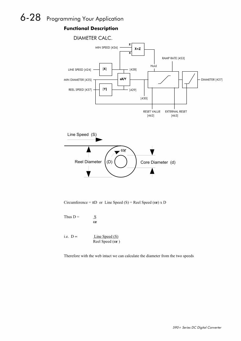
6-28 Programming Your Application
590+ Series DC Digital Converter
Functional Description
|X||X||X||X|
|Y||Y||Y||Y|REEL SPEED [437]
X<ZX<ZX<ZX<ZMIN SPEED [426]
RESET VALUE EXTERNAL RESET
MIN DIAMETER [425] DIAMETER [427]
RAMP RATE [453]
LINE SPEED [424]
[462] [463]
[430]
[428]
[429]
aX/YaX/YaX/YaX/Y
x
z
Hold
DIAMETER CALC.
Core Diameter (d)
Line Speed (S)
Reel Diameter
ωr
(D)
Circumference = πD or Line Speed (S) = Reel Speed (ωr) x D
Thus D = Sωr
i.e. D ∝ Line Speed (S)Reel Speed (ωr )
Therefore with the web intact we can calculate the diameter from the two speeds
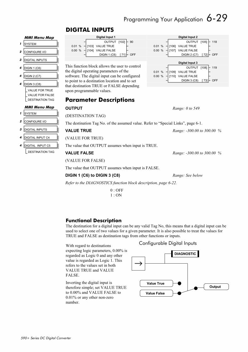
Programming Your Application 6-29
590+ Series DC Digital Converter
DIGITAL INPUTS
This function block allows the user to controlthe digital operating parameters of thesoftware. The digital input can be configuredto point to a destination location and to setthat destination TRUE or FALSE dependingupon programmable values.
Functional DescriptionThe destination for a digital input can be any valid Tag No, this means that a digital input can beused to select one of two values for a given parameter. It is also possible to treat the values forTRUE and FALSE as destination tags from other functions or inputs.
With regard to destinationsexpecting logic parameters, 0.00% isregarded as Logic 0 and any othervalue is regarded as Logic 1. Thisrefers to the values set in bothVALUE TRUE and VALUEFALSE.
Inverting the digital input istherefore simple; set VALUE TRUEto 0.00% and VALUE FALSE to0.01% or any other non-zeronumber.
Digital Input 2– OUTPUT [105] – 118
0.01 % – [106] VALUE TRUE –0.00 % – [107] VALUE FALSE –
– DIGIN 2 (C7) [ 72] – OFF
Digital Input 1– OUTPUT [102] – 90
0.01 % – [103] VALUE TRUE –0.00 % – [104] VALUE FALSE –
– DIGIN 1 (C6) [ 71] – OFF
Digital Input 3– OUTPUT [108] – 119
0.01 % – [109] VALUE TRUE –0.00 % – [110] VALUE FALSE –
– DIGIN 3 (C8) [ 73] – OFF
Parameter DescriptionsOUTPUT Range: 0 to 549
(DESTINATION TAG)
The destination Tag No. of the assumed value. Refer to “Special Links”, page 6-1.
VALUE TRUE Range: -300.00 to 300.00 %
(VALUE FOR TRUE)
The value that OUTPUT assumes when input is TRUE.
VALUE FALSE Range: -300.00 to 300.00 %
(VALUE FOR FALSE)
The value that OUTPUT assumes when input is FALSE.
DIGIN 1 (C6) to DIGIN 3 (C8) Range: See below
Refer to the DIAGNOSTICS function block description, page 6-22.
0 : OFF1 : ON
MMI Menu Map
1 SYSTEM
2 CONFIGURE I/O
3 DIGITAL INPUTS
4 DIGITAL INPUT C4
4 DIGITAL INPUT C5
DESTINATION TAG
MMI Menu Map
1 SYSTEM
2 CONFIGURE I/O
3 DIGITAL INPUTS
4 DIGIN 1 (C6)
4 DIGIN 2 (C7)
4 DIGIN 3 (C8)
VALUE FOR TRUEVALUE FOR FALSEDESTINATION TAG
Configurable Digital Inputs
OutputValue True
Value False
DIAGNOSTIC
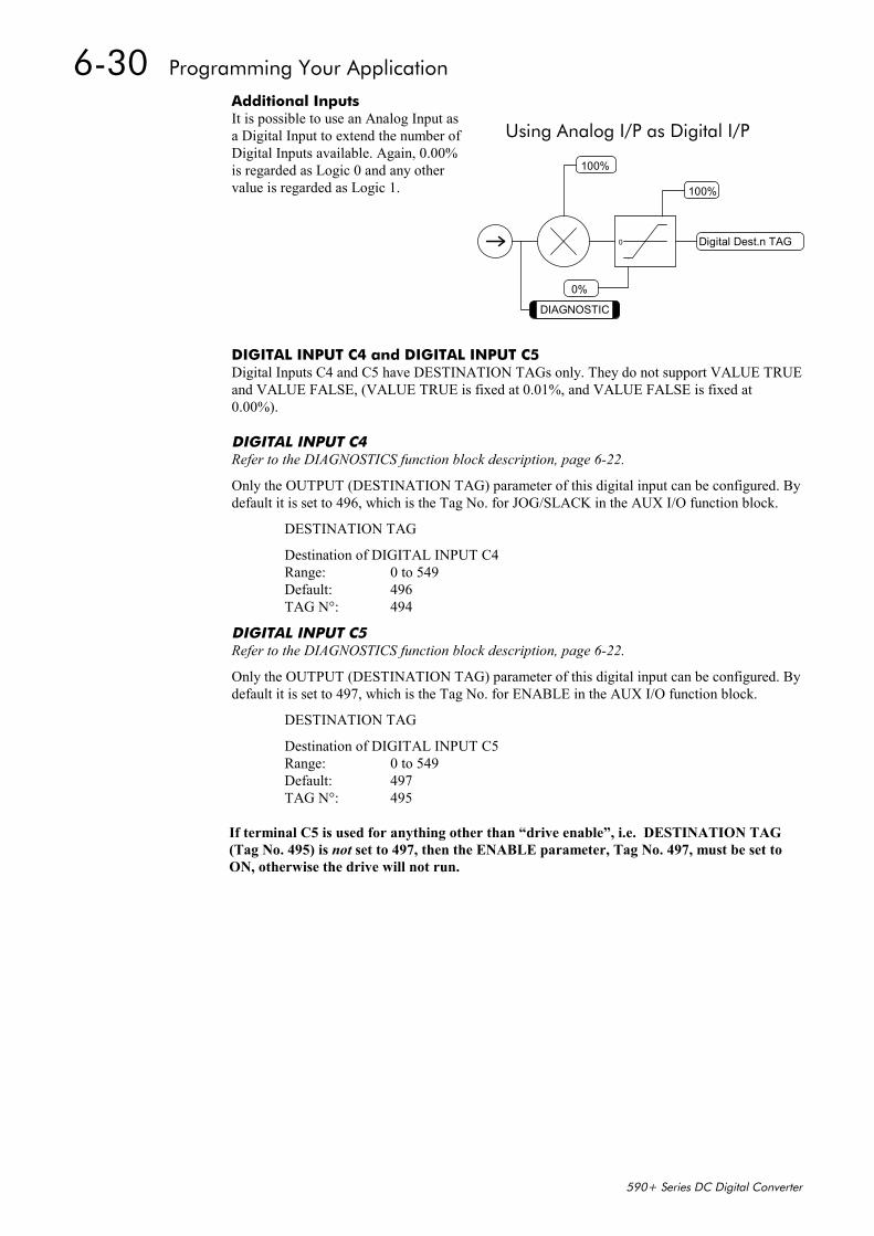
6-30 Programming Your Application
590+ Series DC Digital Converter
Additional InputsIt is possible to use an Analog Input asa Digital Input to extend the number ofDigital Inputs available. Again, 0.00%is regarded as Logic 0 and any othervalue is regarded as Logic 1.
DIGITAL INPUT C4 and DIGITAL INPUT C5Digital Inputs C4 and C5 have DESTINATION TAGs only. They do not support VALUE TRUEand VALUE FALSE, (VALUE TRUE is fixed at 0.01%, and VALUE FALSE is fixed at0.00%).
DIGITAL INPUT C4Refer to the DIAGNOSTICS function block description, page 6-22.
Only the OUTPUT (DESTINATION TAG) parameter of this digital input can be configured. Bydefault it is set to 496, which is the Tag No. for JOG/SLACK in the AUX I/O function block.
DESTINATION TAG
Destination of DIGITAL INPUT C4Range: 0 to 549Default: 496TAG N°: 494
DIGITAL INPUT C5Refer to the DIAGNOSTICS function block description, page 6-22.
Only the OUTPUT (DESTINATION TAG) parameter of this digital input can be configured. Bydefault it is set to 497, which is the Tag No. for ENABLE in the AUX I/O function block.
DESTINATION TAG
Destination of DIGITAL INPUT C5Range: 0 to 549Default: 497TAG N°: 495
If terminal C5 is used for anything other than “drive enable”, i.e. DESTINATION TAG(Tag No. 495) is not set to 497, then the ENABLE parameter, Tag No. 497, must be set toON, otherwise the drive will not run.
Using Analog I/P as Digital I/P
Digital Dest.n TAG
0%
100%
0
100%
DIAGNOSTIC
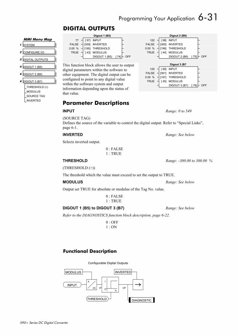
Programming Your Application 6-31
590+ Series DC Digital Converter
DIGITAL OUTPUTS
This function block allows the user to outputdigital parameters within the software toother equipment. The digital output can beconfigured to point to any digital valuewithin the software system and outputinformation depending upon the status ofthat value.
Functional Description
Configurable Digital Outputs
INPUT
THRESHOLD
IP OP
X
|X|
1
0 %
MODULUS
DIAGNOSTIC
INVERTED
Digout 2 (B6)122 – [ 98] INPUT –
FALSE – [360] INVERTED –0.00 % – [196] THRESHOLD –
TRUE – [ 44] MODULUS –– DIGOUT 2 (B6) [ 75] – OFF
Digout 1 (B5)77 – [ 97] INPUT –
FALSE – [359] INVERTED –0.00 % – [195] THRESHOLD –
TRUE – [ 43] MODULUS –– DIGOUT 1 (B5) [ 74] – OFF
MMI Menu Map 1 SYSTEM
2 CONFIGURE I/O
3 DIGITAL OUTPUTS
4 DIGOUT 1 (B5)
4 DIGOUT 2 (B6)
4 DIGOUT 3 (B7)
THRESHOLD (>)MODULUSSOURCE TAGINVERTED
Digout 3 (B7125 – [ 99] INPUT –
FALSE – [361] INVERTED –0.00 % – [197] THRESHOLD –
TRUE – [ 45] MODULUS –– DIGOUT 3 (B7) [ 76] – OFF
Parameter DescriptionsINPUT Range: 0 to 549
(SOURCE TAG)Defines the source of the variable to control the digital output. Refer to “Special Links”,page 6-1.
INVERTED Range: See below
Selects inverted output.
0 : FALSE1 : TRUE
THRESHOLD Range: -300.00 to 300.00 %
(THRESHOLD (>))
The threshold which the value must exceed to set the output to TRUE.
MODULUS Range: See below
Output set TRUE for absolute or modulus of the Tag No. value.
0 : FALSE1 : TRUE
DIGOUT 1 (B5) to DIGOUT 3 (B7) Range: See below
Refer to the DIAGNOSTICS function block description, page 6-22.
0 : OFF1 : ON
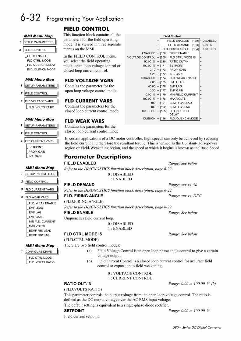
6-32 Programming Your Application
590+ Series DC Digital Converter
FIELD CONTROLThis function block contains all theparameters for the field operatingmode. It is viewed in three separatemenus on the MMI.
In the FIELD CONTROL menu,you select the field operatingmode: open loop voltage control orclosed loop current control.
FLD VOLTAGE VARSContains the parameter for theopen loop voltage control mode.
FLD CURRENT VARSContains the parameters for theclosed loop current control mode.
FLD WEAK VARSContains the parameters for theclosed loop current control mode.
In certain applications of a DC motor controller, high speeds can only be achieved by reducingthe field current and therefore the resultant torque. This is termed as the Constant-Horsepowerregion or Field-Weakening region, and the speed at which it begins is known as the Base Speed.
Field Control– FIELD ENABLED [169] – DISABLED– FIELD DEMAND [183] – 0.00 %– FLD. FIRING ANGLE [184] – 0.00 DEG
ENABLED – [170] FIELD ENABLE –VOLTAGE CONTROL – [209] FLD CTRL MODE IS –
90.00 % – [210] RATIO OUT/IN –100.00 % – [171] SETPOINT –
0.10 – [173] PROP. GAIN –1.28 – [172] INT. GAIN –
DISABLED – [174] FLD. WEAK ENABLE –2.00 – [175] EMF LEAD –
40.00 – [176] EMF LAG –0.30 – [177] EMF GAIN –
10.00 % – [179] MIN FIELD CURRENT –100.00 % – [178] MAX VOLTS –
100 – [191] BEMF FBK LEAD –100 – [192] BEMF FBK LAG –
0.0 SECS – [185] FLD. QUENCHDELAY
–
QUENCH – [186] FLD. QUENCH MODE –
MMI Menu Map
1 SETUP PARAMETERS
2 FIELD CONTROL
FIELD ENABLEFLD CTRL MODEFLD QUENCH DELAYFLD. QUENCH MODE
MMI Menu Map
1 SETUP PARAMETERS
2 FIELD CONTROL
3 FLD VOLTAGE VARS
FLD. VOLTS RATIO
MMI Menu Map
1 SETUP PARAMETERS
2 FIELD CONTROL
3 FLD CURRENT VARS
4 FLD WEAK VARS
FLD. WEAK ENABLEEMF LEADEMF LAGEMF GAINMIN FLD. CURRENTMAX VOLTSBEMF FBK LEADBEMF FBK LAG
MMI Menu Map
1 SETUP PARAMETERS
2 FIELD CONTROL
3 FLD CURRENT VARS
SETPOINTPROP. GAININT. GAIN
MMI Menu Map
1 CONFIGURE DRIVE
FLD CTRL MODEFLD. VOLTS RATIO
Parameter DescriptionsFIELD ENABLED Range: See belowRefer to the DIAGNOSTICS function block description, page 6-22.
0 : DISABLED1 : ENABLED
FIELD DEMAND Range: xxx.xx %Refer to the DIAGNOSTICS function block description, page 6-22.FLD. FIRING ANGLE Range: xxx.xx DEG(FLD.FIRING ANGLE)Refer to the DIAGNOSTICS function block description, page 6-22.FIELD ENABLE Range: See belowUnquenches field current loop.
0 : DISABLED1 : ENABLED
FLD CTRL MODE IS Range: See below(FLD.CTRL MODE)There are two field control modes:
(a) Field Voltage Control is an open loop phase angle control to give a certainvoltage output.
(b) Field Current Control is a closed loop current control for accurate fieldcontrol or expansion to field weakening.
0 : VOLTAGE CONTROL1 : CURRENT CONTROL
RATIO OUT/IN Range: 0.00 to 100.00 % (h)(FLD.VOLTS RATIO)This parameter controls the output voltage from the open loop voltage control. The ratio isdefined as the DC output voltage over the AC RMS input voltage.The default setting is equivalent to a single-phase diode rectifier.SETPOINT Range: 0.00 to 100.00 %Field current setpoint.
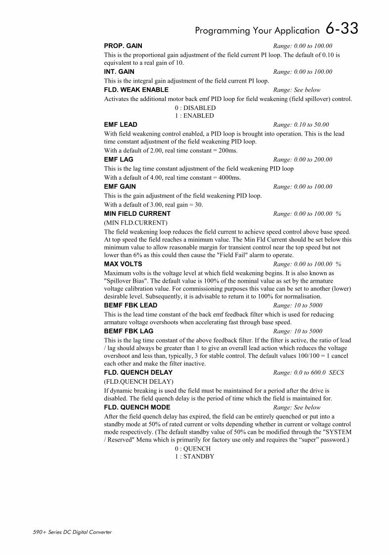
Programming Your Application 6-33
590+ Series DC Digital Converter
PROP. GAIN Range: 0.00 to 100.00This is the proportional gain adjustment of the field current PI loop. The default of 0.10 isequivalent to a real gain of 10.INT. GAIN Range: 0.00 to 100.00This is the integral gain adjustment of the field current PI loop.FLD. WEAK ENABLE Range: See belowActivates the additional motor back emf PID loop for field weakening (field spillover) control.
0 : DISABLED1 : ENABLED
EMF LEAD Range: 0.10 to 50.00With field weakening control enabled, a PID loop is brought into operation. This is the leadtime constant adjustment of the field weakening PID loop.With a default of 2.00, real time constant = 200ms.EMF LAG Range: 0.00 to 200.00This is the lag time constant adjustment of the field weakening PID loopWith a default of 4.00, real time constant = 4000ms.EMF GAIN Range: 0.00 to 100.00This is the gain adjustment of the field weakening PID loop.With a default of 3.00, real gain = 30.MIN FIELD CURRENT Range: 0.00 to 100.00 %(MIN FLD.CURRENT)The field weakening loop reduces the field current to achieve speed control above base speed.At top speed the field reaches a minimum value. The Min Fld Current should be set below thisminimum value to allow reasonable margin for transient control near the top speed but notlower than 6% as this could then cause the "Field Fail" alarm to operate.MAX VOLTS Range: 0.00 to 100.00 %Maximum volts is the voltage level at which field weakening begins. It is also known as"Spillover Bias". The default value is 100% of the nominal value as set by the armaturevoltage calibration value. For commissioning purposes this value can be set to another (lower)desirable level. Subsequently, it is advisable to return it to 100% for normalisation.BEMF FBK LEAD Range: 10 to 5000This is the lead time constant of the back emf feedback filter which is used for reducingarmature voltage overshoots when accelerating fast through base speed.BEMF FBK LAG Range: 10 to 5000This is the lag time constant of the above feedback filter. If the filter is active, the ratio of lead/ lag should always be greater than 1 to give an overall lead action which reduces the voltageovershoot and less than, typically, 3 for stable control. The default values 100/100 = 1 canceleach other and make the filter inactive.FLD. QUENCH DELAY Range: 0.0 to 600.0 SECS(FLD.QUENCH DELAY)If dynamic breaking is used the field must be maintained for a period after the drive isdisabled. The field quench delay is the period of time which the field is maintained for.FLD. QUENCH MODE Range: See belowAfter the field quench delay has expired, the field can be entirely quenched or put into astandby mode at 50% of rated current or volts depending whether in current or voltage controlmode respectively. (The default standby value of 50% can be modified through the "SYSTEM/ Reserved" Menu which is primarily for factory use only and requires the “super” password.)
0 : QUENCH1 : STANDBY
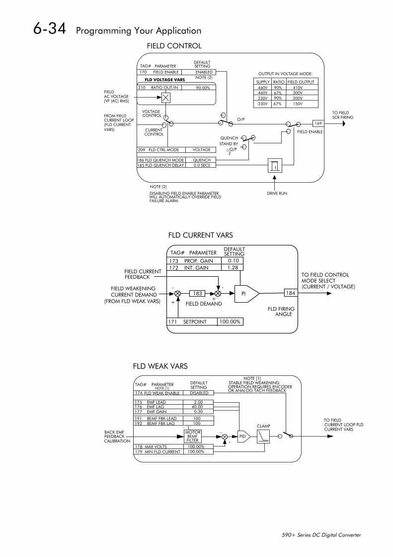
6-34 Programming Your Application
590+ Series DC Digital Converter
FIELD CONTROL
FIELD ENABLE ENABLED
TAG# PARAMETER SETTINGDEFAULT
209 FLD CTRL MODE VOLTAGE
NOTE (2)
210 RATIO OUT/INFIELDAC VOLTAGE[VF (AC) RMS]
FROM FIELDCURRENT LOOP(FLD CURRENT
VOLTAGECONTROL
CONTROLCURRENT
186 FLD QUENCH MODE QUENCH185 FLD QUENCH DELAY 0.0 SECS
SUPPLY FIELD OUTPUTRATIO460V460V230V230V
90%67%90%67%
410V300V200V150V
OUTPUT IN VOLTAGE MODE:
VARS)
169
t
DRIVE RUN
NOTE [2]
DISABLING FIELD ENABLE PARAMETERWILL AUTOMATICALLY OVERRIDE FIELDFAILURE ALARM.
FIELD ENABLE
QUENCHSTAND BY
=O/P2
TO FIELDSCR FIRING
FLD VOLTAGE VARS
O/P
90.00%
170
____
FLD CURRENT VARS
TAG# PARAMETERDEFAULT
173 PROP. GAIN 0.10172 INT. GAIN 1.28
SETTING
PI183
FIELD CURRENTFEEDBACK
FIELD WEAKENINGCURRENT DEMAND
(FROM FLD WEAK VARS)
171 SETPOINT 100.00%
184
FIELD DEMANDFLD FIRING
ANGLE
TO FIELD CONTROLMODE SELECT(CURRENT / VOLTAGE)-
+
-
+
DISABLEDFLD WEAK ENABLE174
175 EMF LEAD176 EMF LAG177 EMF GAIN
191 BEMF FBK LEAD192 BEMF FBK LAG
MOTORBEMFFILTER
BACK EMFFEEDBACKCALIBRATION
178 MAX VOLTS179 MIN FLD CURRENT
2.0040.000.30
100100
100.00%100.00%
TAG# PARAMETER DEFAULTNOTE [1]
PID+
CLAMP
NOTE [1]STABLE FIELD WEAKENINGOPERATION REQUIRES ENCODEROR ANALOG TACH FEEDBACK
TO FIELDCURRENT LOOP FLDCURRENT VARS
FLD WEAK VARS
-
SETTING
-
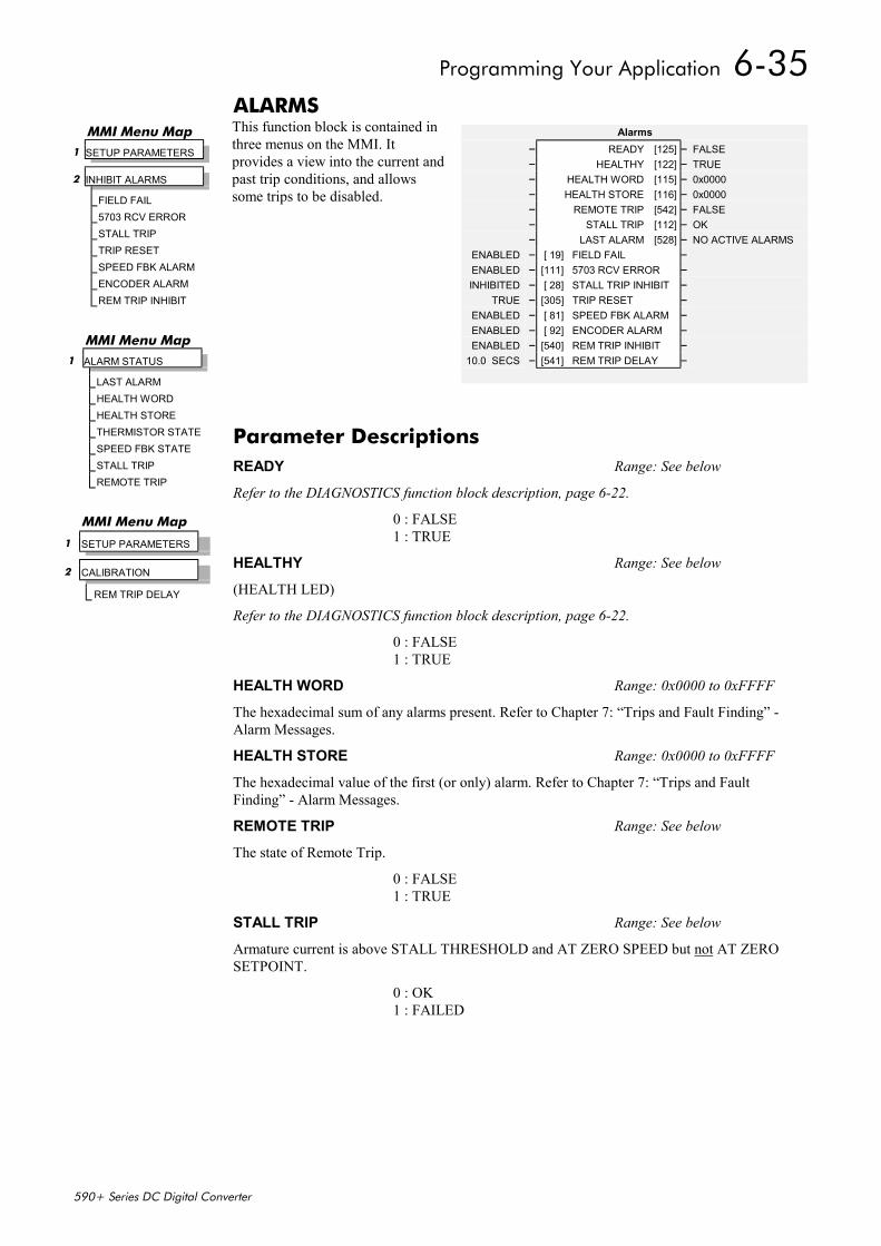
Programming Your Application 6-35
590+ Series DC Digital Converter
ALARMSThis function block is contained inthree menus on the MMI. Itprovides a view into the current andpast trip conditions, and allowssome trips to be disabled.
Alarms– READY [125] – FALSE– HEALTHY [122] – TRUE– HEALTH WORD [115] – 0x0000– HEALTH STORE [116] – 0x0000– REMOTE TRIP [542] – FALSE– STALL TRIP [112] – OK– LAST ALARM [528] – NO ACTIVE ALARMS
ENABLED – [ 19] FIELD FAIL –ENABLED – [111] 5703 RCV ERROR –INHIBITED – [ 28] STALL TRIP INHIBIT –
TRUE – [305] TRIP RESET –ENABLED – [ 81] SPEED FBK ALARM –ENABLED – [ 92] ENCODER ALARM –ENABLED – [540] REM TRIP INHIBIT –
10.0 SECS – [541] REM TRIP DELAY –
MMI Menu Map 1 SETUP PARAMETERS
2 INHIBIT ALARMS
FIELD FAIL5703 RCV ERRORSTALL TRIPTRIP RESETSPEED FBK ALARMENCODER ALARMREM TRIP INHIBIT
MMI Menu Map1 ALARM STATUS
LAST ALARMHEALTH WORDHEALTH STORETHERMISTOR STATESPEED FBK STATESTALL TRIPREMOTE TRIP
MMI Menu Map
1 SETUP PARAMETERS
2 CALIBRATION
REM TRIP DELAY
Parameter DescriptionsREADY Range: See below
Refer to the DIAGNOSTICS function block description, page 6-22.
0 : FALSE1 : TRUE
HEALTHY Range: See below
(HEALTH LED)
Refer to the DIAGNOSTICS function block description, page 6-22.
0 : FALSE1 : TRUE
HEALTH WORD Range: 0x0000 to 0xFFFF
The hexadecimal sum of any alarms present. Refer to Chapter 7: “Trips and Fault Finding” -Alarm Messages.
HEALTH STORE Range: 0x0000 to 0xFFFF
The hexadecimal value of the first (or only) alarm. Refer to Chapter 7: “Trips and FaultFinding” - Alarm Messages.
REMOTE TRIP Range: See below
The state of Remote Trip.
0 : FALSE1 : TRUE
STALL TRIP Range: See below
Armature current is above STALL THRESHOLD and AT ZERO SPEED but not AT ZEROSETPOINT.
0 : OK1 : FAILED
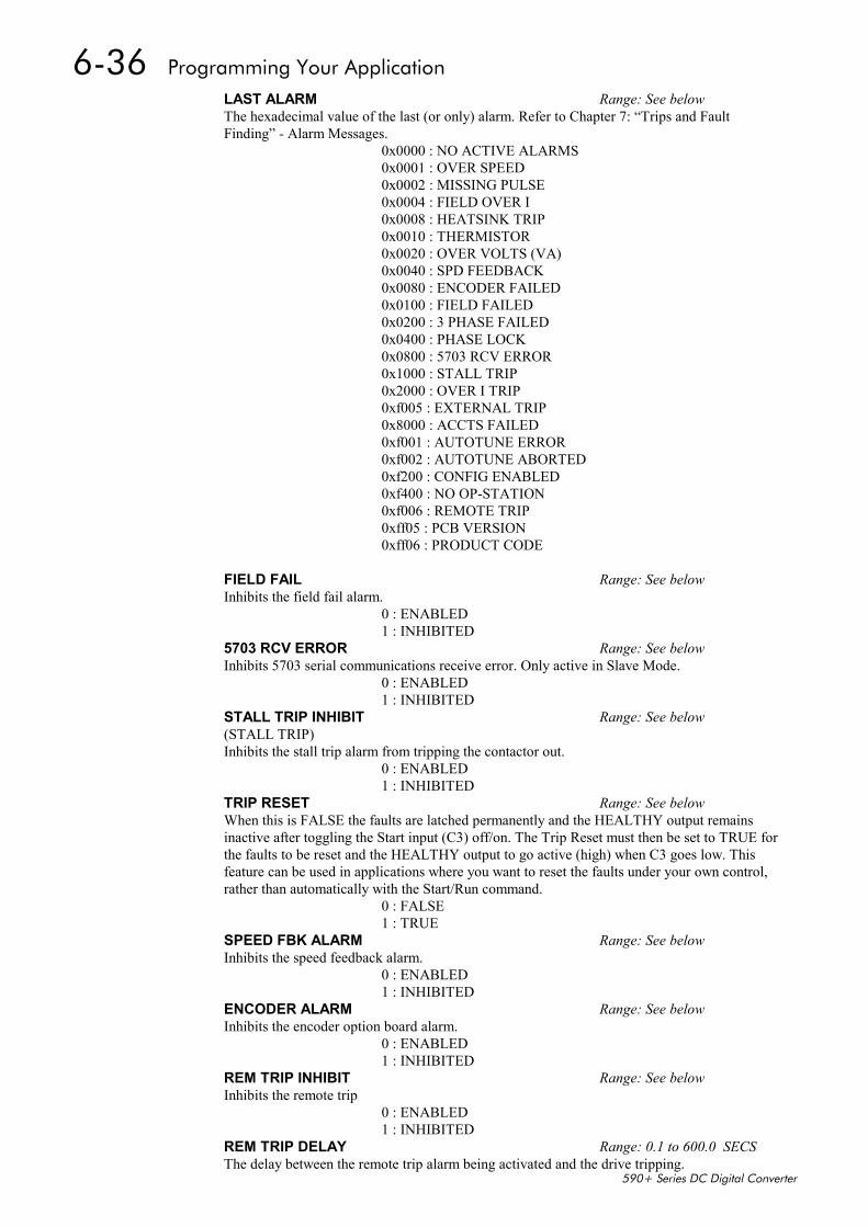
6-36 Programming Your Application
590+ Series DC Digital Converter
LAST ALARM Range: See belowThe hexadecimal value of the last (or only) alarm. Refer to Chapter 7: “Trips and FaultFinding” - Alarm Messages.
0x0000 : NO ACTIVE ALARMS0x0001 : OVER SPEED0x0002 : MISSING PULSE0x0004 : FIELD OVER I0x0008 : HEATSINK TRIP0x0010 : THERMISTOR0x0020 : OVER VOLTS (VA)0x0040 : SPD FEEDBACK0x0080 : ENCODER FAILED0x0100 : FIELD FAILED0x0200 : 3 PHASE FAILED0x0400 : PHASE LOCK0x0800 : 5703 RCV ERROR0x1000 : STALL TRIP0x2000 : OVER I TRIP0xf005 : EXTERNAL TRIP0x8000 : ACCTS FAILED0xf001 : AUTOTUNE ERROR0xf002 : AUTOTUNE ABORTED0xf200 : CONFIG ENABLED0xf400 : NO OP-STATION0xf006 : REMOTE TRIP0xff05 : PCB VERSION0xff06 : PRODUCT CODE
FIELD FAIL Range: See belowInhibits the field fail alarm.
0 : ENABLED1 : INHIBITED
5703 RCV ERROR Range: See belowInhibits 5703 serial communications receive error. Only active in Slave Mode.
0 : ENABLED1 : INHIBITED
STALL TRIP INHIBIT Range: See below(STALL TRIP)Inhibits the stall trip alarm from tripping the contactor out.
0 : ENABLED1 : INHIBITED
TRIP RESET Range: See belowWhen this is FALSE the faults are latched permanently and the HEALTHY output remainsinactive after toggling the Start input (C3) off/on. The Trip Reset must then be set to TRUE forthe faults to be reset and the HEALTHY output to go active (high) when C3 goes low. Thisfeature can be used in applications where you want to reset the faults under your own control,rather than automatically with the Start/Run command.
0 : FALSE1 : TRUE
SPEED FBK ALARM Range: See belowInhibits the speed feedback alarm.
0 : ENABLED1 : INHIBITED
ENCODER ALARM Range: See belowInhibits the encoder option board alarm.
0 : ENABLED1 : INHIBITED
REM TRIP INHIBIT Range: See belowInhibits the remote trip
0 : ENABLED1 : INHIBITED
REM TRIP DELAY Range: 0.1 to 600.0 SECSThe delay between the remote trip alarm being activated and the drive tripping.
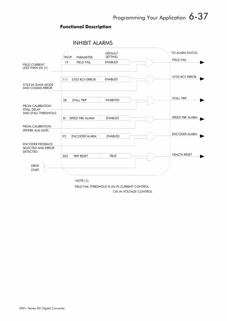
Programming Your Application 6-37
590+ Series DC Digital Converter
Functional Description
19 FIELD FAIL ENABLED
111 5703 RCV ERROR ENABLED
28 STALL TRIP INHIBITED
81 SPEED FBK ALARM ENABLED
92 ENCODER ALARM ENABLED
305 TRIP RESET TRUE
FIELD CURRENTLESS THAN 6% [1]
5703 IN SLAVE MODEAND COMMS ERROR
FROM CALIBRATIONSTALL DELAYAND STALL THRESHOLD
FROM CALIBRATIONSPDFBK ALM LEVEL
ENCODER FEEDBACKSELECTED AND ERRORDETECTED
DRIVESTART
TO ALARM STATUS
FIELD FAIL
5703 RCV ERROR
STALL TRIP
SPEED FBK ALARM
ENCODER ALARM
HEALTH RESET
NOTE [1]:
FIELD FAIL THRESHOLD IS 6% IN CURRENT CONTROL
12% IN VOLTAGE CONTROL
INHIBIT ALARMS
TAG# PARAMETERDEFAULTSETTING
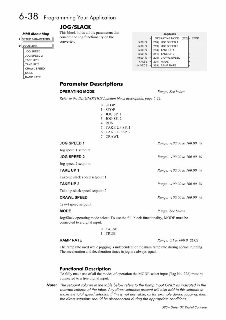
6-38 Programming Your Application
590+ Series DC Digital Converter
JOG/SLACKThis block holds all the parameters thatconcern the Jog functionality on theconverter.
Functional DescriptionTo fully make use of all the modes of operation the MODE select input (Tag No. 228) must beconnected to a free digital input.
Note: The setpoint column in the table below refers to the Ramp Input ONLY as indicated in therelevant column of the table. Any direct setpoints present will also add to this setpoint tomake the total speed setpoint. If this is not desirable, as for example during jogging, thenthe direct setpoints should be disconnected during the appropriate conditions.
Jog/Slack– OPERATING MODE [212] – STOP
5.00 % – [218] JOG SPEED 1 –-5.00 % – [219] JOG SPEED 2 –5.00 % – [253] TAKE UP 1 –
-5.00 % – [254] TAKE UP 2 –10.00 % – [225] CRAWL SPEED –
FALSE – [228] MODE –1.0 SECS – [355] RAMP RATE –
MMI Menu Map 1 SETUP PARAMETERS
2 JOG/SLACK
JOG SPEED 1JOG SPEED 2TAKE UP 1TAKE UP 2CRAWL SPEEDMODERAMP RATE
Parameter DescriptionsOPERATING MODE Range: See below
Refer to the DIAGNOSTICS function block description, page 6-22.
0 : STOP1 : STOP2 : JOG SP. 13 : JOG SP. 24 : RUN5 : TAKE UP SP. 16 : TAKE UP SP. 27 : CRAWL
JOG SPEED 1 Range: -100.00 to 100.00 %
Jog speed 1 setpoint.
JOG SPEED 2 Range: -100.00 to 100.00 %
Jog speed 2 setpoint.
TAKE UP 1 Range: -100.00 to 100.00 %
Take-up slack speed setpoint 1.
TAKE UP 2 Range: -100.00 to 100.00 %
Take-up slack speed setpoint 2.
CRAWL SPEED Range: -100.00 to 100.00 %
Crawl speed setpoint.
MODE Range: See below
Jog/Slack operating mode select. To use the full block functionality, MODE must beconnected to a digital input.
0 : FALSE1 : TRUE
RAMP RATE Range: 0.1 to 600.0 SECS
The ramp rate used while jogging is independent of the main ramp rate during normal running.The acceleration and deceleration times in jog are always equal.
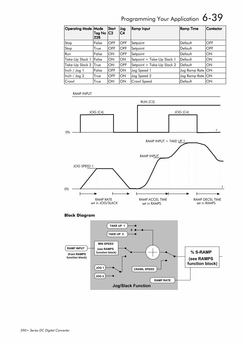
Programming Your Application 6-39
590+ Series DC Digital Converter
Operating ModeOperating ModeOperating ModeOperating Mode ModeModeModeModeTag NoTag NoTag NoTag No228228228228
StartStartStartStartC3C3C3C3
JogJogJogJogC4C4C4C4
Ramp InputRamp InputRamp InputRamp Input Ramp TimeRamp TimeRamp TimeRamp Time ContactorContactorContactorContactor
Stop False OFF OFF Setpoint Default OFFStop True OFF OFF Setpoint Default OFFRun False ON OFF Setpoint Default ONTake-Up Slack 1 False ON ON Setpoint + Take-Up Slack 1 Default ONTake-Up Slack 2 True ON OFF Setpoint + Take-Up Slack 2 Default ONInch / Jog 1 False OFF ON Jog Speed 1 Jog Ramp Rate ONInch / Jog 2 True OFF ON Jog Speed 2 Jog Ramp Rate ONCrawl True ON ON Crawl Speed Default ON
RAMP INPUT
JOG (C4)
RUN (C3)
JOG (C4)
t0%
0%
JOG SPEED 1
RAMP RATEset in JOG/SLACK
RAMP INPUT
RAMP INPUT + TAKE UP 1
t
RAMP ACCEL TIMEset in RAMPS
RAMP DECEL TIMEset in RAMPS
Block Diagram
RAMP INPUT
JOG 1
JOG 2
TAKE UP 1
% S-RAMP
CRAWL SPEED
0TAKE UP 2
MIN SPEED
Jog/Slack FunctionRAMP RATE
(see RAMPSfunction block)
(see RAMPSfunction block)(from RAMPS
function block)
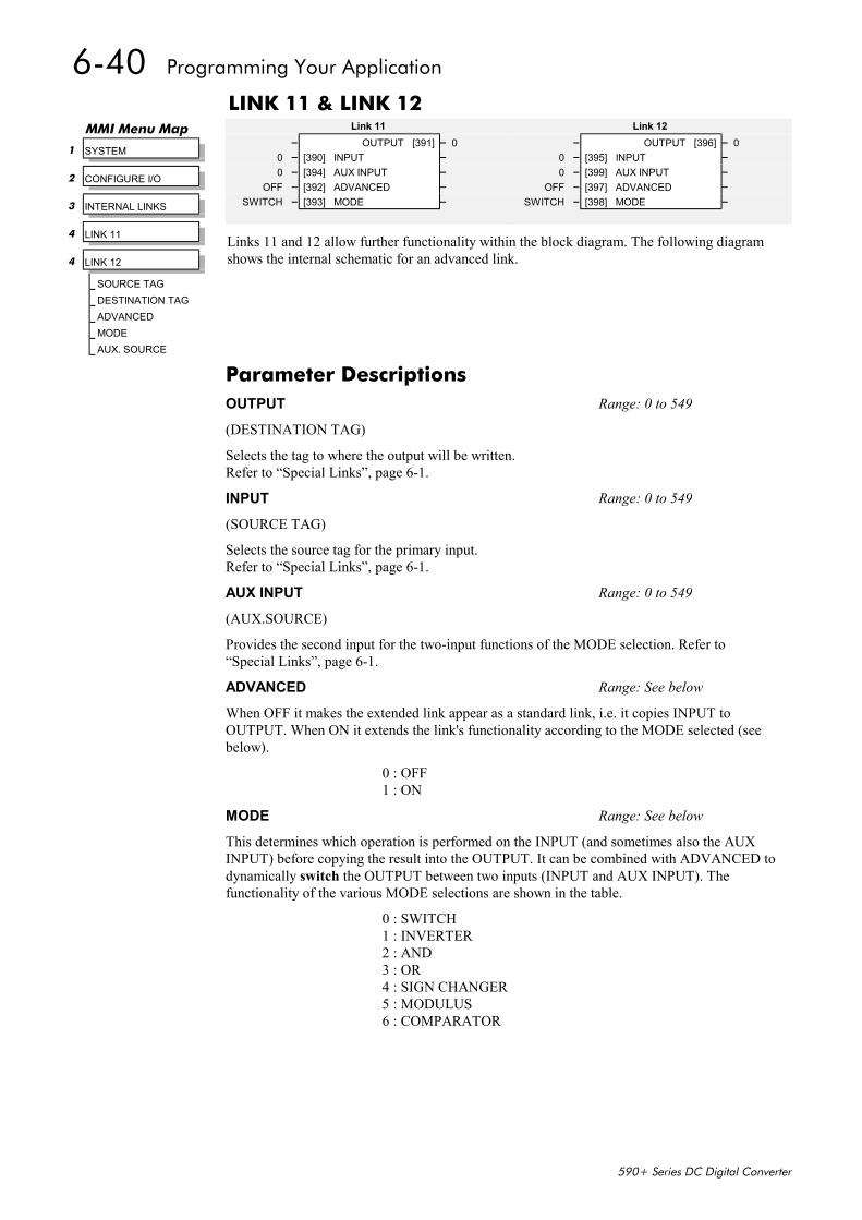
6-40 Programming Your Application
590+ Series DC Digital Converter
LINK 11 & LINK 12
Links 11 and 12 allow further functionality within the block diagram. The following diagramshows the internal schematic for an advanced link.
Link 11– OUTPUT [391] – 0
0 – [390] INPUT –0 – [394] AUX INPUT –
OFF – [392] ADVANCED –SWITCH – [393] MODE –
Link 12– OUTPUT [396] – 0
0 – [395] INPUT –0 – [399] AUX INPUT –
OFF – [397] ADVANCED –SWITCH – [398] MODE –
MMI Menu Map
1 SYSTEM
2 CONFIGURE I/O
3 INTERNAL LINKS
4 LINK 11
4 LINK 12
SOURCE TAGDESTINATION TAGADVANCEDMODEAUX. SOURCE
Parameter DescriptionsOUTPUT Range: 0 to 549
(DESTINATION TAG)
Selects the tag to where the output will be written.Refer to “Special Links”, page 6-1.
INPUT Range: 0 to 549
(SOURCE TAG)
Selects the source tag for the primary input.Refer to “Special Links”, page 6-1.
AUX INPUT Range: 0 to 549
(AUX.SOURCE)
Provides the second input for the two-input functions of the MODE selection. Refer to“Special Links”, page 6-1.
ADVANCED Range: See below
When OFF it makes the extended link appear as a standard link, i.e. it copies INPUT toOUTPUT. When ON it extends the link's functionality according to the MODE selected (seebelow).
0 : OFF1 : ON
MODE Range: See below
This determines which operation is performed on the INPUT (and sometimes also the AUXINPUT) before copying the result into the OUTPUT. It can be combined with ADVANCED todynamically switch the OUTPUT between two inputs (INPUT and AUX INPUT). Thefunctionality of the various MODE selections are shown in the table.
0 : SWITCH1 : INVERTER2 : AND3 : OR4 : SIGN CHANGER5 : MODULUS6 : COMPARATOR
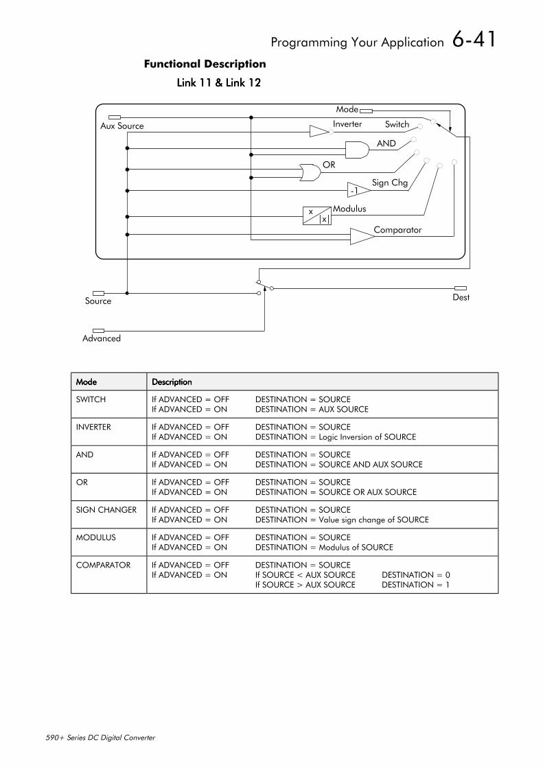
Programming Your Application 6-41
590+ Series DC Digital Converter
Functional Description
Link 11 & Link 12Link 11 & Link 12Link 11 & Link 12Link 11 & Link 12
-1
x|x|
Aux Source
Mode
Source
Advanced
Dest
SwitchInverter
AND
OR
Sign Chg
Modulus
Comparator
ModeModeModeMode DescriptionDescriptionDescriptionDescription
SWITCH If ADVANCED = OFF DESTINATION = SOURCEIf ADVANCED = ON DESTINATION = AUX SOURCE
INVERTER If ADVANCED = OFF DESTINATION = SOURCEIf ADVANCED = ON DESTINATION = Logic Inversion of SOURCE
AND If ADVANCED = OFF DESTINATION = SOURCEIf ADVANCED = ON DESTINATION = SOURCE AND AUX SOURCE
OR If ADVANCED = OFF DESTINATION = SOURCEIf ADVANCED = ON DESTINATION = SOURCE OR AUX SOURCE
SIGN CHANGER If ADVANCED = OFF DESTINATION = SOURCEIf ADVANCED = ON DESTINATION = Value sign change of SOURCE
MODULUS If ADVANCED = OFF DESTINATION = SOURCEIf ADVANCED = ON DESTINATION = Modulus of SOURCE
COMPARATOR If ADVANCED = OFF DESTINATION = SOURCEIf ADVANCED = ON If SOURCE < AUX SOURCE DESTINATION = 0
If SOURCE > AUX SOURCE DESTINATION = 1

6-42 Programming Your Application
590+ Series DC Digital Converter
MENUSThis function block allows selection of eitherthe full menu structure, or a reduced menustructure for easier navigation of the menu. Italso selects the display language for theMMI.
MMI Menu Map1 MENUS
FULL MENUSLANGUAGE
MenusENABLED – [ 37] FULL MENUS –
0.000 – [547] SPEED FBK FILTER –ENGLISH – [304] LANGUAGE –
MMI Menu Map 1 SETUP PARAMETERS
2 SPEED LOOP
SPD.FBK. FILTERParameter DescriptionsFULL MENUS Range: See below
When enabled, the full MMI menu structure is displayed on the MMI.
0 : DISABLED1 : ENABLED
SPEED FBK FILTER Range: 0.000 to 1.000
(SPD.FBK.FILTER)
A simple filter function that is applied to speed feedback to reduce ripple caused by low linecount encoders. A value of 0 disables the filter action ,and 1.00 is the maximum value. Atypical value would be between 0.5 and 0.75.
INCREASING THE FILTER VALUE MAY MAKE THE SPEED LOOP UNSTABLE.
The filter time constant τ in milliseconds can be calculated from the following equation:
=
α
τ1
3.3.
eLog
Where α is the value of SPD FBK FILTER. A value of 0.5 equates to a filter time of 4.8ms,0.8 to 14.7ms, and 0.9 to 31.2ms.
LANGUAGE Range: See below
Selects the MMI display language. Other languages are available, please contact EurothermDrives. Refer also to Chapter 5: “The Operator Station” - Selecting the Display Language.
0 : ENGLISH1 : Other
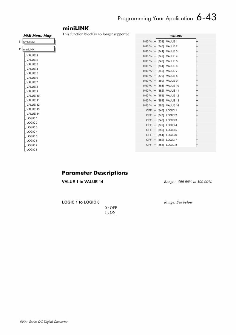
Programming Your Application 6-43
590+ Series DC Digital Converter
miniLINKThis function block is no longer supported.MMI Menu Map
1 SYSTEM
2 miniLINK
VALUE 1VALUE 2VALUE 3VALUE 4VALUE 5VALUE 6VALUE 7VALUE 8VALUE 9VALUE 10VALUE 11VALUE 12VALUE 13VALUE 14LOGIC 1LOGIC 2LOGIC 3LOGIC 4LOGIC 5LOGIC 6LOGIC 7LOGIC 8
miniLINK
0.00 % – [339] VALUE 1 –
0.00 % – [340] VALUE 2 –
0.00 % – [341] VALUE 3 –
0.00 % – [342] VALUE 4 –
0.00 % – [343] VALUE 5 –
0.00 % – [344] VALUE 6 –
0.00 % – [345] VALUE 7 –
0.00 % – [379] VALUE 8 –
0.00 % – [380] VALUE 9 –
0.00 % – [381] VALUE 10 –
0.00 % – [382] VALUE 11 –
0.00 % – [383] VALUE 12 –
0.00 % – [384] VALUE 13 –
0.00 % – [385] VALUE 14 –
OFF – [346] LOGIC 1 –
OFF – [347] LOGIC 2 –
OFF – [348] LOGIC 3 –
OFF – [349] LOGIC 4 –
OFF – [350] LOGIC 5 –
OFF – [351] LOGIC 6 –
OFF – [352] LOGIC 7 –
OFF – [353] LOGIC 8 –
Parameter DescriptionsVALUE 1 to VALUE 14 Range: -300.00% to 300.00%
LOGIC 1 to LOGIC 8 Range: See below0 : OFF1 : ON
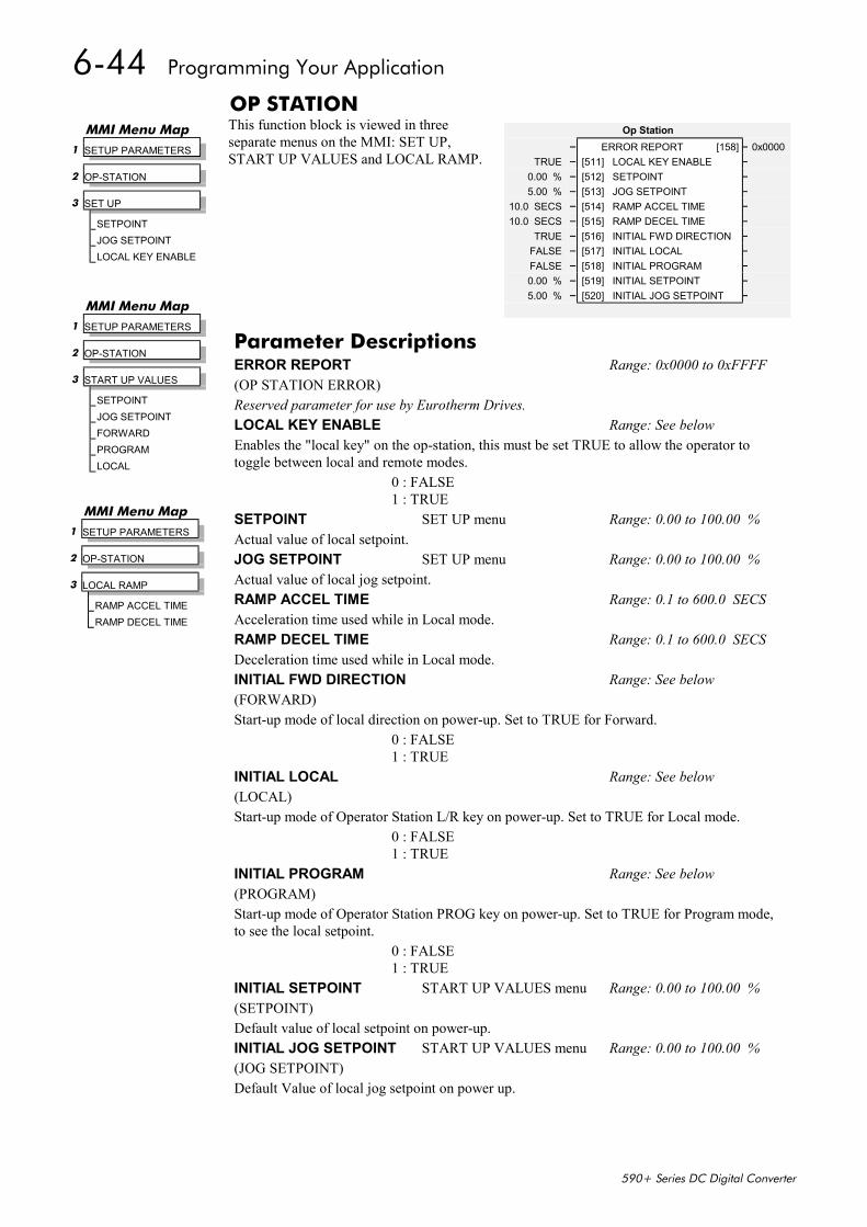
6-44 Programming Your Application
590+ Series DC Digital Converter
OP STATIONThis function block is viewed in threeseparate menus on the MMI: SET UP,START UP VALUES and LOCAL RAMP.
Op Station– ERROR REPORT [158] – 0x0000
TRUE – [511] LOCAL KEY ENABLE –0.00 % – [512] SETPOINT –5.00 % – [513] JOG SETPOINT –
10.0 SECS – [514] RAMP ACCEL TIME –10.0 SECS – [515] RAMP DECEL TIME –
TRUE – [516] INITIAL FWD DIRECTION –FALSE – [517] INITIAL LOCAL –FALSE – [518] INITIAL PROGRAM –0.00 % – [519] INITIAL SETPOINT –5.00 % – [520] INITIAL JOG SETPOINT –
MMI Menu Map 1 SETUP PARAMETERS
2 OP-STATION
3 SET UP
SETPOINTJOG SETPOINTLOCAL KEY ENABLE
MMI Menu Map 1 SETUP PARAMETERS
2 OP-STATION
3 START UP VALUES
SETPOINTJOG SETPOINTFORWARDPROGRAMLOCAL
Parameter DescriptionsERROR REPORT Range: 0x0000 to 0xFFFF(OP STATION ERROR)Reserved parameter for use by Eurotherm Drives.LOCAL KEY ENABLE Range: See belowEnables the "local key" on the op-station, this must be set TRUE to allow the operator totoggle between local and remote modes.
0 : FALSE1 : TRUE
SETPOINT SET UP menu Range: 0.00 to 100.00 %Actual value of local setpoint.JOG SETPOINT SET UP menu Range: 0.00 to 100.00 %Actual value of local jog setpoint.RAMP ACCEL TIME Range: 0.1 to 600.0 SECSAcceleration time used while in Local mode.RAMP DECEL TIME Range: 0.1 to 600.0 SECSDeceleration time used while in Local mode.INITIAL FWD DIRECTION Range: See below(FORWARD)Start-up mode of local direction on power-up. Set to TRUE for Forward.
0 : FALSE1 : TRUE
INITIAL LOCAL Range: See below(LOCAL)Start-up mode of Operator Station L/R key on power-up. Set to TRUE for Local mode.
0 : FALSE1 : TRUE
INITIAL PROGRAM Range: See below(PROGRAM)Start-up mode of Operator Station PROG key on power-up. Set to TRUE for Program mode,to see the local setpoint.
0 : FALSE1 : TRUE
INITIAL SETPOINT START UP VALUES menu Range: 0.00 to 100.00 %(SETPOINT)Default value of local setpoint on power-up.INITIAL JOG SETPOINT START UP VALUES menu Range: 0.00 to 100.00 %(JOG SETPOINT)Default Value of local jog setpoint on power up.
MMI Menu Map 1 SETUP PARAMETERS
2 OP-STATION
3 LOCAL RAMP
RAMP ACCEL TIMERAMP DECEL TIME

Programming Your Application 6-45
590+ Series DC Digital Converter
Functional Description
Local Ramp
Accel Time
Decel Time
% S-Ramp
Up Key
Down Key
Reset Value
Local Setpoint
Stop Ramp
Figure 5. 2 Local Setpoint (only active when the drive is in Local mode)

6-46 Programming Your Application
590+ Series DC Digital Converter
PASSWORD (MMI only)Use this MMI menu to activate or deactivate the password protection feature. Refer to Chapter 5:“The Operator Station” - Password Protection for further instruction.
MMI Menu Map1 PASSWORD
ENTER PASSWORDBY-PASS PASSWORDCHANGE PASSWORD
Parameter DescriptionsENTER PASSWORD Tag 120 Range: 0x0000 to 0xFFFFDefault = 0x0000.
BY-PASS PASSWORD Tag 526 Range: See belowDefault = FALSEReserved parameter for use by Eurotherm Drives.
0 : FALSE1 : TRUE
CHANGE PASSWORD Tag 121 Range: 0x0000 to 0xFFFFDefault = 0x0000.

Programming Your Application 6-47
590+ Series DC Digital Converter
PIDThis is a general purpose PID block whichcan be used for many different closed loopcontrol applications. The PID feedback canbe loadcell tension, dancer position or anyother transducer feedback such as pressure,flow etc.
Features:• Independent adjustment of gain and time
constants.• Additional first-order filter (F).• Functions P, PI, PD, PID with/without F
individually selected.• Ratio and divider for scaling each input.• Independent positive and negative limits.• Output scaler (Trim).• Gain profiled by diameter for centre-
driven winder control.
Pid– PID OUTPUT [417] – 0.00 %– PID CLAMPED [416] – FALSE– PID ERROR [415] – 0.00 %
1.0 – [404] PROP. GAIN –5.00 SECS – [402] INT. TIME CONST. –
0.000 SECS – [401] DERIVATIVE TC –100.00 % – [405] POSITIVE LIMIT –
-100.00 % – [406] NEGATIVE LIMIT –0.2000 – [407] O/P SCALER (TRIM) –
0.00 % – [410] INPUT 1 –0.00 % – [411] INPUT 2 –1.0000 – [412] RATIO 1 –1.0000 – [413] RATIO 2 –1.0000 – [418] DIVIDER 1 –1.0000 – [414] DIVIDER 2 –
ENABLED – [408] ENABLE –OFF – [409] INT. DEFEAT –
0.100 SECS – [403] FILTER T.C. –0 – [473] MODE –
20.00 % – [474] MIN PROFILE GAIN –– PROFILED GAIN [475] – 0.0
MMI Menu Map 1 SETUP PARAMETERS
2 SPECIAL BLOCKS
3 PID
PROP. GAINSPD.INT.TIMEDERIVATIVE TCPOSITIVE LIMITNEGATIVE LIMITO/P SCALER(TRIM)INPUT 1INPUT 2RATIO 1RATIO 2DIVIDER 1DIVIDER 2ENABLEINT. DEFEATFILTER T.C.MODEMIN PROFILE GAINPROFILED GAIN
Parameter DescriptionsPID OUTPUT Range: xxx.xx %
Refer to the DIAGNOSTICS function block description, page 6-22.
PID CLAMPED Range: See below
Refer to the DIAGNOSTICS function block description, page 6-22.
0 : FALSE1 : TRUE
PID ERROR Range: xxx.xx %
Refer to the DIAGNOSTICS function block description, page 6-22.
PROP. GAIN Range: 0.0 to 100.0
This is a pure gain factor which shifts up or down the whole Bode PID transfer functionleaving the time constants unaffected. A value of P = 10.0 means that, for an error of 5%, theproportional part (initial step) of the PID output will be: 10 x [ 1 + (Td/Ti) ] x 5 % , i.e. approx. 50% for Td << Ti.
INT. TIME CONST. Range: 0.01 to 100.00 SECS
(SPD.INT.TIME)
The integrator time constant (Ti)
DERIVATIVE TC Range: 0.000 to 10.000 SECS
The differentiator time constant (Td). When Td = 0 the transfer function of the block becomesa P+I.
POSITIVE LIMIT Range: 0.00 to 105.00 %
The upper limit of the PID algorithm.
NEGATIVE LIMIT Range: -105.00 to 0.00 %
The lower limit of the PID algorithm.
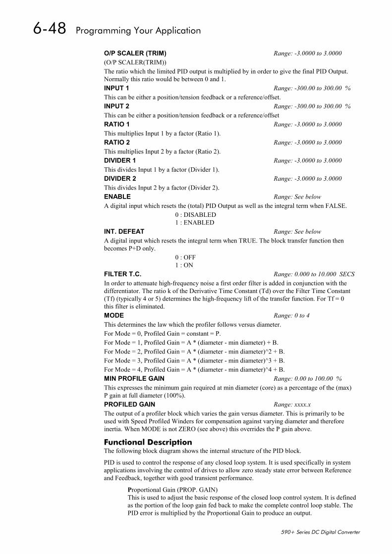
6-48 Programming Your Application
590+ Series DC Digital Converter
Functional DescriptionThe following block diagram shows the internal structure of the PID block.
PID is used to control the response of any closed loop system. It is used specifically in systemapplications involving the control of drives to allow zero steady state error between Referenceand Feedback, together with good transient performance.
Proportional Gain (PROP. GAIN)This is used to adjust the basic response of the closed loop control system. It is definedas the portion of the loop gain fed back to make the complete control loop stable. ThePID error is multiplied by the Proportional Gain to produce an output.
O/P SCALER (TRIM) Range: -3.0000 to 3.0000(O/P SCALER(TRIM))The ratio which the limited PID output is multiplied by in order to give the final PID Output.Normally this ratio would be between 0 and 1.INPUT 1 Range: -300.00 to 300.00 %This can be either a position/tension feedback or a reference/offset.INPUT 2 Range: -300.00 to 300.00 %This can be either a position/tension feedback or a reference/offsetRATIO 1 Range: -3.0000 to 3.0000This multiplies Input 1 by a factor (Ratio 1).RATIO 2 Range: -3.0000 to 3.0000This multiplies Input 2 by a factor (Ratio 2).DIVIDER 1 Range: -3.0000 to 3.0000This divides Input 1 by a factor (Divider 1).DIVIDER 2 Range: -3.0000 to 3.0000This divides Input 2 by a factor (Divider 2).ENABLE Range: See belowA digital input which resets the (total) PID Output as well as the integral term when FALSE.
0 : DISABLED1 : ENABLED
INT. DEFEAT Range: See belowA digital input which resets the integral term when TRUE. The block transfer function thenbecomes P+D only.
0 : OFF1 : ON
FILTER T.C. Range: 0.000 to 10.000 SECSIn order to attenuate high-frequency noise a first order filter is added in conjunction with thedifferentiator. The ratio k of the Derivative Time Constant (Td) over the Filter Time Constant(Tf) (typically 4 or 5) determines the high-frequency lift of the transfer function. For Tf = 0this filter is eliminated.MODE Range: 0 to 4This determines the law which the profiler follows versus diameter.For Mode = 0, Profiled Gain = constant = P.For Mode = 1, Profiled Gain = A * (diameter - min diameter) + B.For Mode = 2, Profiled Gain = A * (diameter - min diameter)^2 + B.For Mode = 3, Profiled Gain = A * (diameter - min diameter)^3 + B.For Mode = 4, Profiled Gain = A * (diameter - min diameter)^4 + B.MIN PROFILE GAIN Range: 0.00 to 100.00 %This expresses the minimum gain required at min diameter (core) as a percentage of the (max)P gain at full diameter (100%).PROFILED GAIN Range: xxxx.xThe output of a profiler block which varies the gain versus diameter. This is primarily to beused with Speed Profiled Winders for compensation against varying diameter and thereforeinertia. When MODE is not ZERO (see above) this overrides the P gain above.
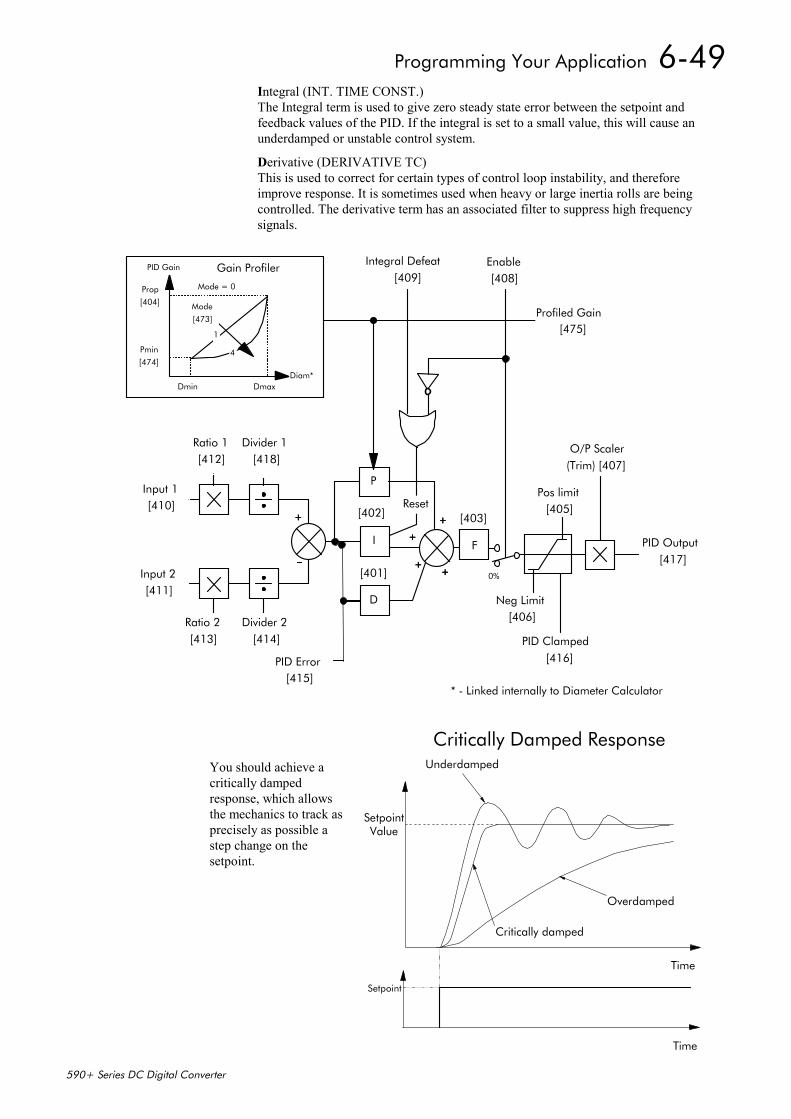
Programming Your Application 6-49
590+ Series DC Digital Converter
Integral (INT. TIME CONST.)The Integral term is used to give zero steady state error between the setpoint andfeedback values of the PID. If the integral is set to a small value, this will cause anunderdamped or unstable control system.
Derivative (DERIVATIVE TC)This is used to correct for certain types of control loop instability, and thereforeimprove response. It is sometimes used when heavy or large inertia rolls are beingcontrolled. The derivative term has an associated filter to suppress high frequencysignals.
++++
Input 1[410]
Ratio 1[412]
Divider 1[418]
Input 2[411]
Ratio 2[413]
Divider 2[414]
F
[403]
D
[401]
I
[402]
P
PID Output[417]
++++
++++
++++++++
Neg Limit[406]
Pos limit[405]
O/P Scaler(Trim) [407]
PID Error[415]
Enable [408]
Integral Defeat[409]
Reset
Prop[404]
Pmin[474]
Dmin Dmax
Mode
[473]
Mode = 0
1
4
Diam*
PID Gain
Profiled Gain[475]
Gain Profiler
PID Clamped[416]
0%
* - Linked internally to Diameter Calculator
You should achieve acritically dampedresponse, which allowsthe mechanics to track asprecisely as possible astep change on thesetpoint.
Critically Damped ResponseUnderdamped
Critically damped
Overdamped
SetpointValue
Setpoint
Time
Time
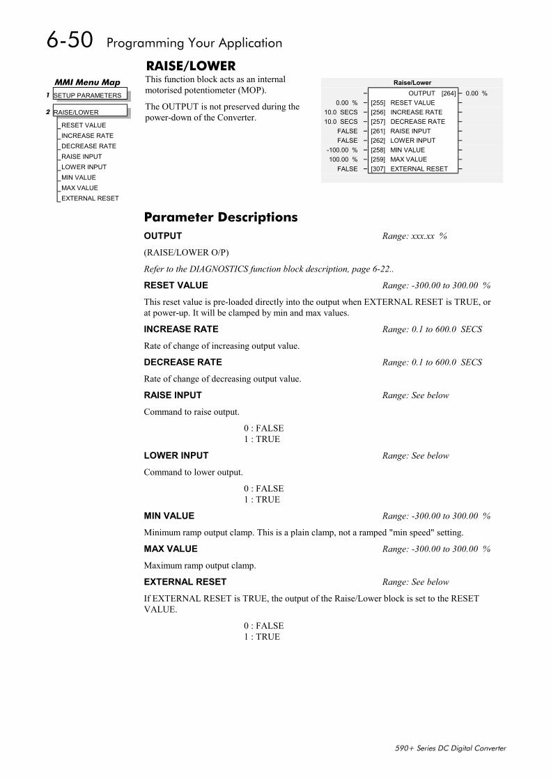
6-50 Programming Your Application
590+ Series DC Digital Converter
RAISE/LOWERThis function block acts as an internalmotorised potentiometer (MOP).
The OUTPUT is not preserved during thepower-down of the Converter.
Raise/Lower– OUTPUT [264] – 0.00 %
0.00 % – [255] RESET VALUE –10.0 SECS – [256] INCREASE RATE –10.0 SECS – [257] DECREASE RATE –
FALSE – [261] RAISE INPUT –FALSE – [262] LOWER INPUT –
-100.00 % – [258] MIN VALUE –100.00 % – [259] MAX VALUE –
FALSE – [307] EXTERNAL RESET –
MMI Menu Map 1 SETUP PARAMETERS
2 RAISE/LOWER
RESET VALUEINCREASE RATEDECREASE RATERAISE INPUTLOWER INPUTMIN VALUEMAX VALUEEXTERNAL RESET
Parameter DescriptionsOUTPUT Range: xxx.xx %
(RAISE/LOWER O/P)
Refer to the DIAGNOSTICS function block description, page 6-22..
RESET VALUE Range: -300.00 to 300.00 %
This reset value is pre-loaded directly into the output when EXTERNAL RESET is TRUE, orat power-up. It will be clamped by min and max values.
INCREASE RATE Range: 0.1 to 600.0 SECS
Rate of change of increasing output value.
DECREASE RATE Range: 0.1 to 600.0 SECS
Rate of change of decreasing output value.
RAISE INPUT Range: See below
Command to raise output.
0 : FALSE1 : TRUE
LOWER INPUT Range: See below
Command to lower output.
0 : FALSE1 : TRUE
MIN VALUE Range: -300.00 to 300.00 %
Minimum ramp output clamp. This is a plain clamp, not a ramped "min speed" setting.
MAX VALUE Range: -300.00 to 300.00 %
Maximum ramp output clamp.
EXTERNAL RESET Range: See below
If EXTERNAL RESET is TRUE, the output of the Raise/Lower block is set to the RESETVALUE.
0 : FALSE1 : TRUE
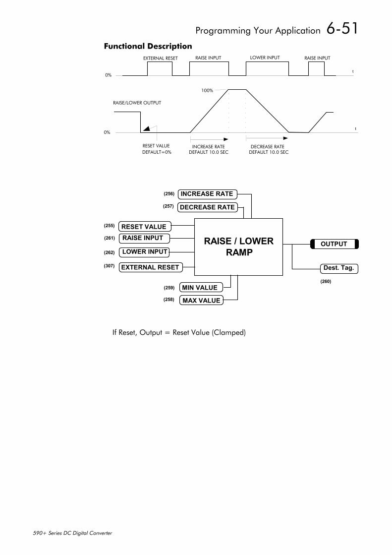
Programming Your Application 6-51
590+ Series DC Digital Converter
Functional Description
0%
EXTERNAL RESET RAISE INPUT LOWER INPUT RAISE INPUT
100%
0%
RAISE/LOWER OUTPUT
RESET VALUEDEFAULT=0%
INCREASE RATEDEFAULT 10.0 SEC
DECREASE RATEDEFAULT 10.0 SEC
t
t
If Reset, Output = Reset Value (Clamped)
RESET VALUERAISE INPUT
MIN VALUE
LOWER INPUT
MAX VALUE
EXTERNAL RESET
RAISE / LOWERRAMP
Dest. Tag.
OUTPUT
(260)
(258)
(259)
(307)
(262)
(261)
(255)
(256)
(257)
INCREASE RATE
DECREASE RATE
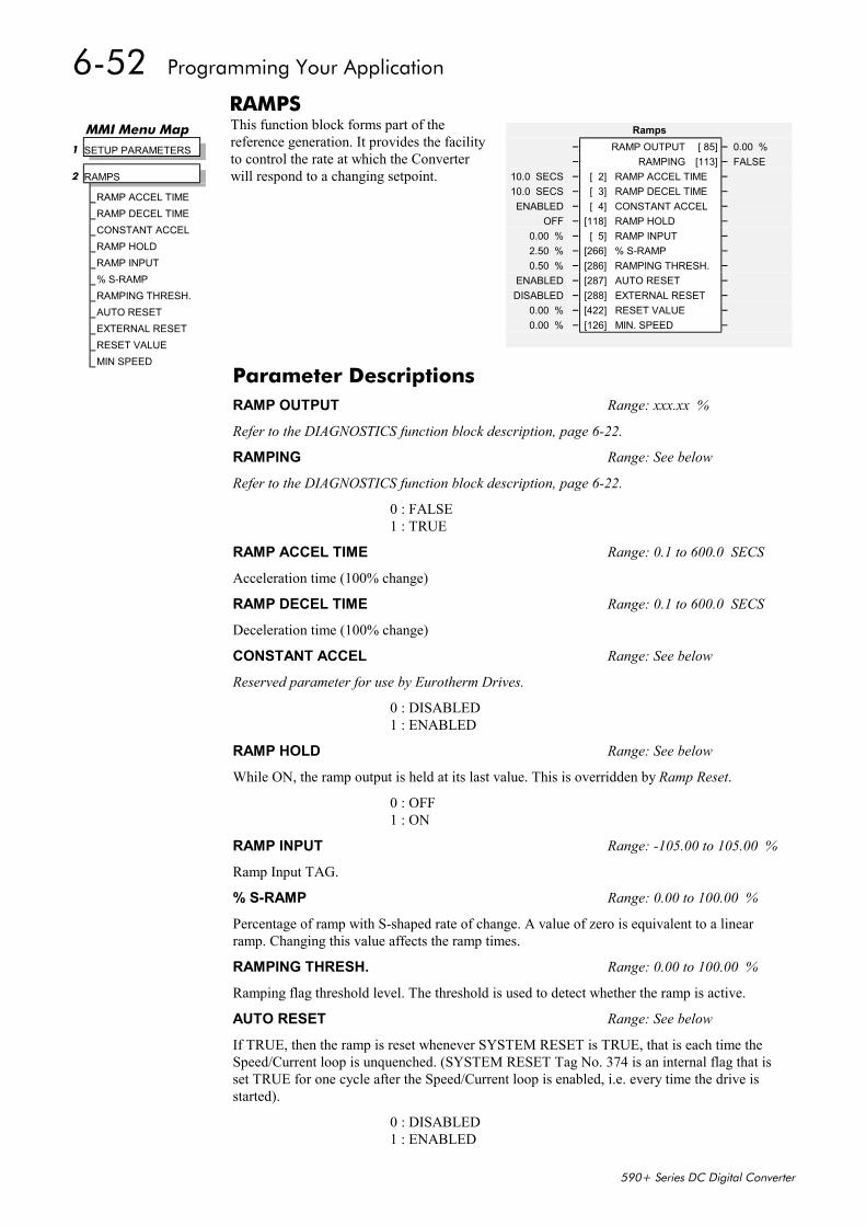
6-52 Programming Your Application
590+ Series DC Digital Converter
RAMPSThis function block forms part of thereference generation. It provides the facilityto control the rate at which the Converterwill respond to a changing setpoint.
Ramps– RAMP OUTPUT [ 85] – 0.00 %– RAMPING [113] – FALSE
10.0 SECS – [ 2] RAMP ACCEL TIME –10.0 SECS – [ 3] RAMP DECEL TIME –ENABLED – [ 4] CONSTANT ACCEL –
OFF – [118] RAMP HOLD –0.00 % – [ 5] RAMP INPUT –2.50 % – [266] % S-RAMP –0.50 % – [286] RAMPING THRESH. –
ENABLED – [287] AUTO RESET –DISABLED – [288] EXTERNAL RESET –
0.00 % – [422] RESET VALUE –0.00 % – [126] MIN. SPEED –
MMI Menu Map 1 SETUP PARAMETERS
2 RAMPS
RAMP ACCEL TIMERAMP DECEL TIMECONSTANT ACCELRAMP HOLDRAMP INPUT% S-RAMPRAMPING THRESH.AUTO RESETEXTERNAL RESETRESET VALUEMIN SPEED
Parameter DescriptionsRAMP OUTPUT Range: xxx.xx %
Refer to the DIAGNOSTICS function block description, page 6-22.
RAMPING Range: See below
Refer to the DIAGNOSTICS function block description, page 6-22.
0 : FALSE1 : TRUE
RAMP ACCEL TIME Range: 0.1 to 600.0 SECS
Acceleration time (100% change)
RAMP DECEL TIME Range: 0.1 to 600.0 SECS
Deceleration time (100% change)
CONSTANT ACCEL Range: See below
Reserved parameter for use by Eurotherm Drives.
0 : DISABLED1 : ENABLED
RAMP HOLD Range: See below
While ON, the ramp output is held at its last value. This is overridden by Ramp Reset.
0 : OFF1 : ON
RAMP INPUT Range: -105.00 to 105.00 %
Ramp Input TAG.
% S-RAMP Range: 0.00 to 100.00 %
Percentage of ramp with S-shaped rate of change. A value of zero is equivalent to a linearramp. Changing this value affects the ramp times.
RAMPING THRESH. Range: 0.00 to 100.00 %
Ramping flag threshold level. The threshold is used to detect whether the ramp is active.
AUTO RESET Range: See below
If TRUE, then the ramp is reset whenever SYSTEM RESET is TRUE, that is each time theSpeed/Current loop is unquenched. (SYSTEM RESET Tag No. 374 is an internal flag that isset TRUE for one cycle after the Speed/Current loop is enabled, i.e. every time the drive isstarted).
0 : DISABLED1 : ENABLED
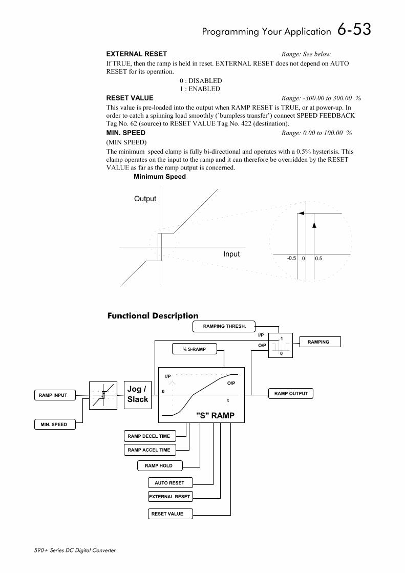
Programming Your Application 6-53
590+ Series DC Digital Converter
Functional Description
RAMP INPUT
MIN. SPEED
Jog /
I/P
O/P1
0
RAMP DECEL TIME
RAMP ACCEL TIME
RAMP HOLD
AUTO RESET
EXTERNAL RESET
RESET VALUE
Slack
"S" RAMP
0
I/PO/P
t
% S-RAMP
RAMPING THRESH.
RAMPING
RAMP OUTPUT
EXTERNAL RESET Range: See belowIf TRUE, then the ramp is held in reset. EXTERNAL RESET does not depend on AUTORESET for its operation.
0 : DISABLED1 : ENABLED
RESET VALUE Range: -300.00 to 300.00 %This value is pre-loaded into the output when RAMP RESET is TRUE, or at power-up. Inorder to catch a spinning load smoothly (`bumpless transfer’) connect SPEED FEEDBACKTag No. 62 (source) to RESET VALUE Tag No. 422 (destination).MIN. SPEED Range: 0.00 to 100.00 %(MIN SPEED)The minimum speed clamp is fully bi-directional and operates with a 0.5% hysterisis. Thisclamp operates on the input to the ramp and it can therefore be overridden by the RESETVALUE as far as the ramp output is concerned.
Input
Output
Minimum Speed
-0.5 0 0.5
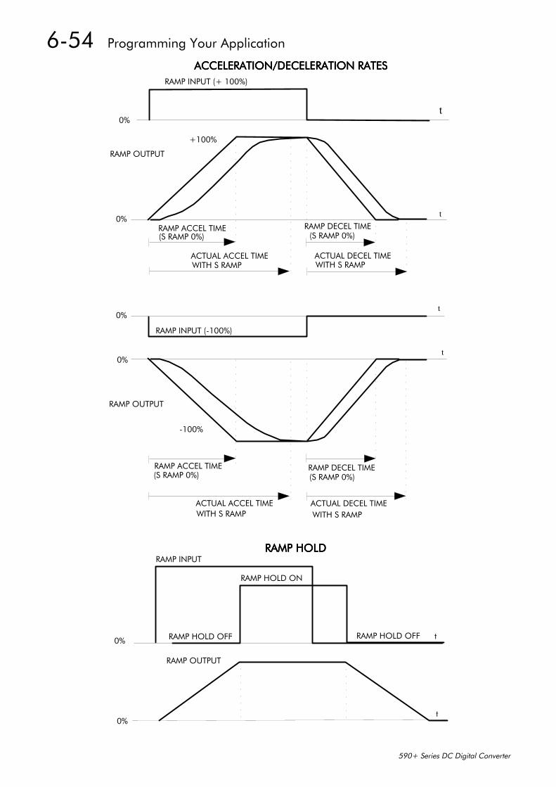
6-54 Programming Your Application
590+ Series DC Digital Converter
t
RAMP INPUT (+ 100%)
0%
+100%
RAMP OUTPUT
RAMP ACCEL TIME(S RAMP 0%)
RAMP DECEL TIME(S RAMP 0%)
ACTUAL ACCEL TIMEWITH S RAMP
ACTUAL DECEL TIMEWITH S RAMP
t0%
t
t
0%
0%
RAMP OUTPUT
-100%
RAMP INPUT (-100%)
RAMP ACCEL TIME(S RAMP 0%)
RAMP DECEL TIME(S RAMP 0%)
ACTUAL ACCEL TIMEWITH S RAMP
ACTUAL DECEL TIMEWITH S RAMP
0% RAMP HOLD OFF
RAMP INPUT
RAMP HOLD ON
RAMP HOLD OFF t
t0%
RAMP OUTPUT
ACCELERATION/DECELERATION RATESACCELERATION/DECELERATION RATESACCELERATION/DECELERATION RATESACCELERATION/DECELERATION RATES
RAMP HOLDRAMP HOLDRAMP HOLDRAMP HOLD
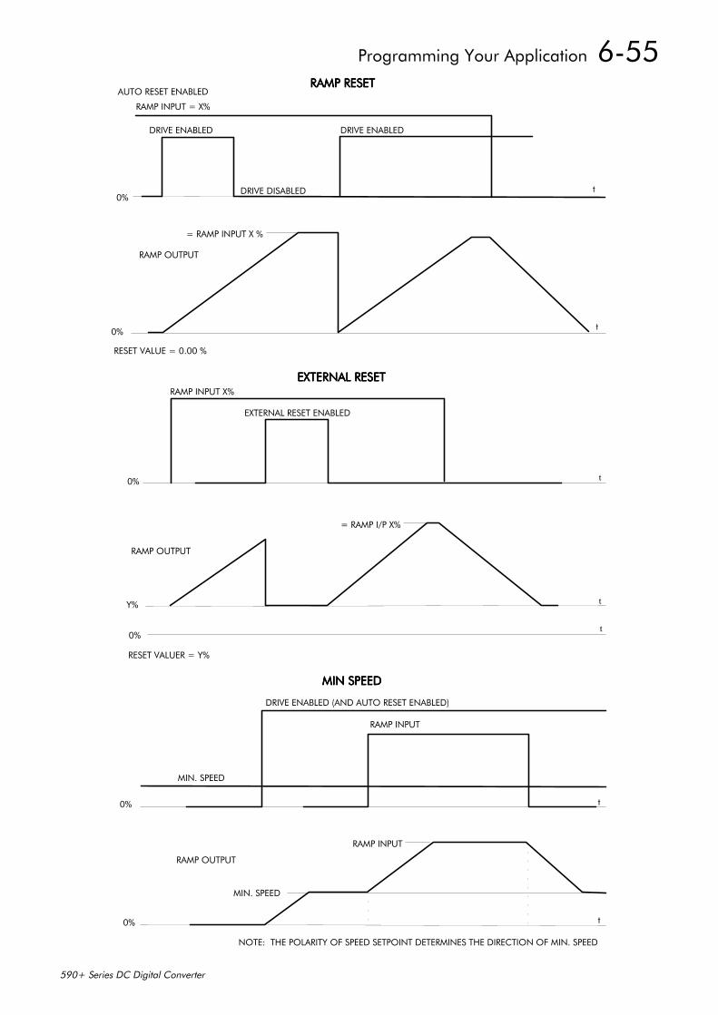
Programming Your Application 6-55
590+ Series DC Digital Converter
RAMP RESETRAMP RESETRAMP RESETRAMP RESETAUTO RESET ENABLED
RAMP INPUT = X%
DRIVE ENABLED DRIVE ENABLED
0%DRIVE DISABLED t
= RAMP INPUT X %
RAMP OUTPUT
0% t
RESET VALUE = 0.00 %
EXTERNAL RESETEXTERNAL RESETEXTERNAL RESETEXTERNAL RESETRAMP INPUT X%
EXTERNAL RESET ENABLED
0%
RAMP OUTPUT
= RAMP I/P X%
t
0%t
RESET VALUER = Y%
Y% t
MIN SPEEDMIN SPEEDMIN SPEEDMIN SPEED
DRIVE ENABLED (AND AUTO RESET ENABLED)
RAMP INPUT
MIN. SPEED
0% t
RAMP INPUT
RAMP OUTPUT
MIN. SPEED
0% t
NOTE: THE POLARITY OF SPEED SETPOINT DETERMINES THE DIRECTION OF MIN. SPEED
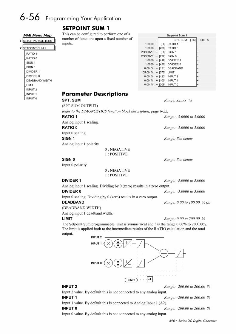
6-56 Programming Your Application
590+ Series DC Digital Converter
SETPOINT SUM 1This can be configured to perform one of anumber of functions upon a fixed number ofinputs.
Setpoint Sum 1– SPT. SUM [ 86] – 0.00 %
1.0000 – [ 6] RATIO 1 –1.0000 – [208] RATIO 0 –
POSITIVE – [ 8] SIGN 1 –POSITIVE – [292] SIGN 0 –
1.0000 – [419] DIVIDER 1 –1.0000 – [420] DIVIDER 0 –
0.00 % – [131] DEADBAND –105.00 % – [375] LIMIT –
0.00 % – [423] INPUT 2 –0.00 % – [100] INPUT 1 –0.00 % – [309] INPUT 0 –
MMI Menu Map 1 SETUP PARAMETERS
2 SETPOINT SUM 1
RATIO 1RATIO 0SIGN 1SIGN 0DIVIDER 1DIVIDER 0DEADBAND WIDTHLIMITINPUT 2INPUT 1INPUT 0
Parameter DescriptionsSPT. SUM Range: xxx.xx %(SPT SUM OUTPUT)Refer to the DIAGNOSTICS function block description, page 6-22.RATIO 1 Range: -3.0000 to 3.0000Analog input 1 scaling.RATIO 0 Range: -3.0000 to 3.0000Input 0 scaling.SIGN 1 Range: See belowAnalog input 1 polarity.
0 : NEGATIVE1 : POSITIVE
SIGN 0 Range: See belowInput 0 polarity.
0 : NEGATIVE1 : POSITIVE
DIVIDER 1 Range: -3.0000 to 3.0000Analog input 1 scaling. Dividing by 0 (zero) results in a zero output.DIVIDER 0 Range: -3.0000 to 3.0000Input 0 scaling. Dividing by 0 (zero) results in a zero output.DEADBAND Range: 0.00 to 100.00 % (h)(DEADBAND WIDTH)Analog input 1 deadband width.LIMIT Range: 0.00 to 200.00 %The Setpoint Sum programmable limit is symmetrical and has the range 0.00% to 200.00%.The limit is applied both to the intermediate results of the RATIO calculation and the totaloutput.
-1LIMIT
INPUT 2
INPUT 1
INPUT 0
INPUT 2 Range: -200.00 to 200.00 %Input 2 value. By default this is not connected to any analog input.INPUT 1 Range: -200.00 to 200.00 %Input 1 value. By default this is connected to Analog Input 1 (A2).INPUT 0 Range: -200.00 to 200.00 %Input 0 value. By default this is not connected to any analog input.
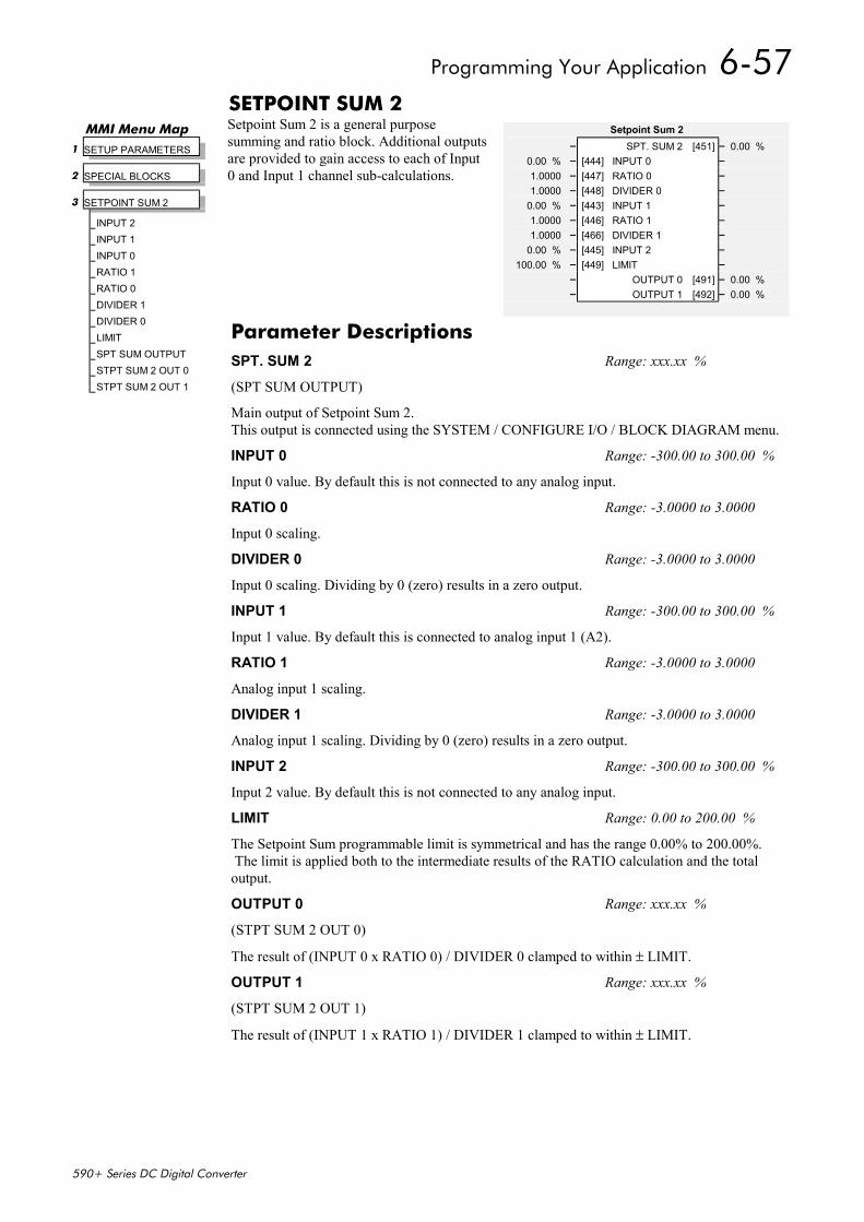
Programming Your Application 6-57
590+ Series DC Digital Converter
SETPOINT SUM 2Setpoint Sum 2 is a general purposesumming and ratio block. Additional outputsare provided to gain access to each of Input0 and Input 1 channel sub-calculations.
Setpoint Sum 2– SPT. SUM 2 [451] – 0.00 %
0.00 % – [444] INPUT 0 –1.0000 – [447] RATIO 0 –1.0000 – [448] DIVIDER 0 –
0.00 % – [443] INPUT 1 –1.0000 – [446] RATIO 1 –1.0000 – [466] DIVIDER 1 –
0.00 % – [445] INPUT 2 –100.00 % – [449] LIMIT –
– OUTPUT 0 [491] – 0.00 %– OUTPUT 1 [492] – 0.00 %
MMI Menu Map 1 SETUP PARAMETERS
2 SPECIAL BLOCKS
3 SETPOINT SUM 2
INPUT 2INPUT 1INPUT 0RATIO 1RATIO 0DIVIDER 1DIVIDER 0LIMITSPT SUM OUTPUTSTPT SUM 2 OUT 0STPT SUM 2 OUT 1
Parameter DescriptionsSPT. SUM 2 Range: xxx.xx %
(SPT SUM OUTPUT)
Main output of Setpoint Sum 2.This output is connected using the SYSTEM / CONFIGURE I/O / BLOCK DIAGRAM menu.
INPUT 0 Range: -300.00 to 300.00 %
Input 0 value. By default this is not connected to any analog input.
RATIO 0 Range: -3.0000 to 3.0000
Input 0 scaling.
DIVIDER 0 Range: -3.0000 to 3.0000
Input 0 scaling. Dividing by 0 (zero) results in a zero output.
INPUT 1 Range: -300.00 to 300.00 %
Input 1 value. By default this is connected to analog input 1 (A2).
RATIO 1 Range: -3.0000 to 3.0000
Analog input 1 scaling.
DIVIDER 1 Range: -3.0000 to 3.0000
Analog input 1 scaling. Dividing by 0 (zero) results in a zero output.
INPUT 2 Range: -300.00 to 300.00 %
Input 2 value. By default this is not connected to any analog input.
LIMIT Range: 0.00 to 200.00 %
The Setpoint Sum programmable limit is symmetrical and has the range 0.00% to 200.00%. The limit is applied both to the intermediate results of the RATIO calculation and the totaloutput.
OUTPUT 0 Range: xxx.xx %
(STPT SUM 2 OUT 0)
The result of (INPUT 0 x RATIO 0) / DIVIDER 0 clamped to within ± LIMIT.
OUTPUT 1 Range: xxx.xx %
(STPT SUM 2 OUT 1)
The result of (INPUT 1 x RATIO 1) / DIVIDER 1 clamped to within ± LIMIT.
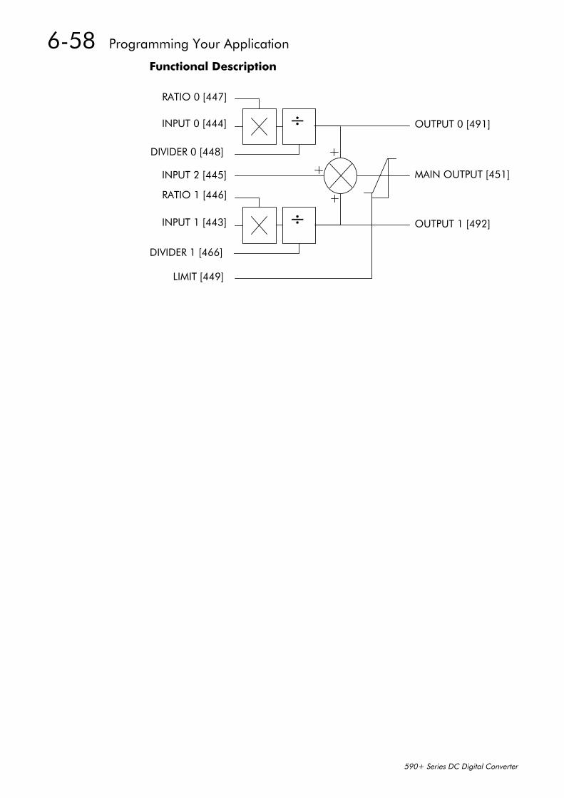
6-58 Programming Your Application
590+ Series DC Digital Converter
Functional Description
INPUT 2 [445]
INPUT 1 [443]
RATIO 1 [446]
INPUT 0 [444]
RATIO 0 [447]
DIVIDER 0 [448]
DIVIDER 1 [466]
÷
÷
LIMIT [449]
OUTPUT 1 [492]
OUTPUT 0 [491]
MAIN OUTPUT [451]
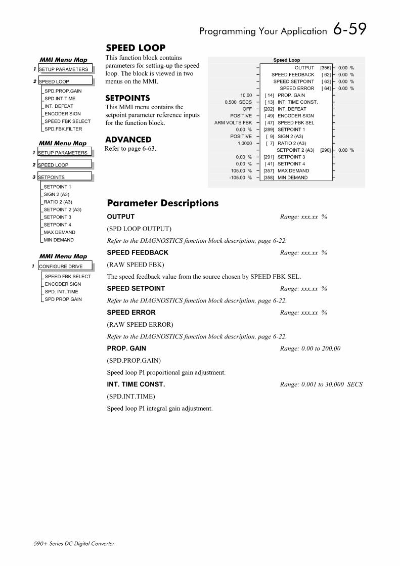
Programming Your Application 6-59
590+ Series DC Digital Converter
SPEED LOOPThis function block containsparameters for setting-up the speedloop. The block is viewed in twomenus on the MMI.
SETPOINTSThis MMI menu contains thesetpoint parameter reference inputsfor the function block.
ADVANCEDRefer to page 6-63.
Speed Loop– OUTPUT [356] – 0.00 %– SPEED FEEDBACK [ 62] – 0.00 %– SPEED SETPOINT [ 63] – 0.00 %– SPEED ERROR [ 64] – 0.00 %
10.00 – [ 14] PROP. GAIN –0.500 SECS – [ 13] INT. TIME CONST. –
OFF – [202] INT. DEFEAT –POSITIVE – [ 49] ENCODER SIGN –
ARM VOLTS FBK – [ 47] SPEED FBK SEL –0.00 % – [289] SETPOINT 1 –
POSITIVE – [ 9] SIGN 2 (A3) –1.0000 – [ 7] RATIO 2 (A3) –
– SETPOINT 2 (A3) [290] – 0.00 %0.00 % – [291] SETPOINT 3 –0.00 % – [ 41] SETPOINT 4 –
105.00 % – [357] MAX DEMAND –-105.00 % – [358] MIN DEMAND –
MMI Menu Map 1 SETUP PARAMETERS
2 SPEED LOOP
SPD.PROP.GAINSPD.INT.TIMEINT. DEFEATENCODER SIGNSPEED FBK SELECTSPD.FBK.FILTER
MMI Menu Map 1 SETUP PARAMETERS
2 SPEED LOOP
3 SETPOINTS
SETPOINT 1SIGN 2 (A3)RATIO 2 (A3)SETPOINT 2 (A3)SETPOINT 3SETPOINT 4MAX DEMANDMIN DEMAND
MMI Menu Map
1 CONFIGURE DRIVE
SPEED FBK SELECTENCODER SIGNSPD. INT. TIMESPD PROP GAIN
Parameter DescriptionsOUTPUT Range: xxx.xx %
(SPD LOOP OUTPUT)
Refer to the DIAGNOSTICS function block description, page 6-22.
SPEED FEEDBACK Range: xxx.xx %
(RAW SPEED FBK)
The speed feedback value from the source chosen by SPEED FBK SEL.
SPEED SETPOINT Range: xxx.xx %
Refer to the DIAGNOSTICS function block description, page 6-22.
SPEED ERROR Range: xxx.xx %
(RAW SPEED ERROR)
Refer to the DIAGNOSTICS function block description, page 6-22.
PROP. GAIN Range: 0.00 to 200.00
(SPD.PROP.GAIN)
Speed loop PI proportional gain adjustment.
INT. TIME CONST. Range: 0.001 to 30.000 SECS
(SPD.INT.TIME)
Speed loop PI integral gain adjustment.
6-60 Programming Your Application
590+ Series DC Digital Converter
INT. DEFEAT Range: See below
Inhibits the integral part of the speed loop PI control to give proportional only control.
0 : OFF1 : ON
ENCODER SIGN Range: See below
Since the encoder feedback cannot be reversed electrically, the signal polarity can be reversedby the control software.
0 : NEGATIVE1 : POSITIVE
SPEED FBK SEL Range: See below
(SPEED FBK SELECT)
Four options are available:0 : ARM VOLTS FBK1 : ANALOG TACH2 : ENCODER3 : ENCODER/ANALOG
SETPOINT 1 Range: -105.00 to 105.00 %
Speed Setpoint 1 (Default Setpoint Sum 1 O/P).
SIGN 2 (A3) Range: See below
Speed Setpoint 2 Sign.
0 : NEGATIVE1 : POSITIVE
RATIO 2 (A3) Range: -3.0000 to 3.0000
Speed Setpoint 2 Ratio.
SETPOINT 2 (A3) Range: xxx.xx %
Speed Setpoint 2 - Fixed (non-configurable) setpoint scanned synchronously with the currentloop
SETPOINT 3 Range: -105.00 to 105.00 %
Speed Setpoint 3 (Default Ramp O/P).
SETPOINT 4 Range: -105.00 to 105.00 %
Speed Setpoint 4 (Default 5703 I/P).
MAX DEMAND Range: 0.00 to 105.00 %
Sets the maximum input to the speed loop. It is clamped at 105% to allow for overshoot in theexternal loops.
MIN DEMAND Range: -105.00 to 105.00 %
Sets the minimum input to the speed loop.
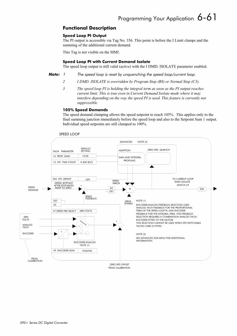
Programming Your Application 6-61
590+ Series DC Digital Converter
Functional Description
Speed Loop PI OutputThe PI output is accessible via Tag No. 356. This point is before the I Limit clamps and thesumming of the additional current demand.
This Tag is not visible on the MMI.
Speed Loop PI with Current Demand IsolateThe speed loop output is still valid (active) with the I DMD. ISOLATE parameter enabled.
Note: 1 The speed loop is reset by unquenching the speed loop/current loop.
2 I DMD. ISOLATE is overridden by Program Stop (B8) or Normal Stop (C3).
3 The speed loop PI is holding the integral term as soon as the PI output reaches current limit. This is true even in Current Demand Isolate mode where it may interfere depending on the way the speed PI is used. This feature is currently not suppressible.
105% Speed DemandsThe speed demand clamping allows the speed setpoint to reach 105%. This applies only to thefinal summing junction immediately before the speed loop and also to the Setpoint Sum 1 output.Individual speed setpoints are still clamped to 100%.
13 INT. TIME CONST
14 PROP. GAIN GAIN AND INTEGRALPROFILING
PI
207
62
64297
ENCODER/ANALOG FEEDBACK SELECTION USEDANALOG TACH FEEDBACK FOR THE PROPORTIONALTERM OF THE SPEED LOOP PI, AND ENCODER FEEDBACK FOR THE INTEGRAL TERM. THIS FEEDBACKSELECTION REQUIRES A COMBINATION ANALOG TACH/ENCODER FITTED TO THE MOTOR.THIS SELECTION CANNOT BE USED WHEN 590 SWITCHABLETACHO CARD IS FITTED.
NOTE (1)
NOTE (2)
SEE ADVANCED SUB MENU FOR ADDITIONAL INFORMATION.
DRIVEENABLE
ZERO SPD. QUENCHADAPTION
202 INT. DEFEAT
10.00
0.500 SECS
OFF
47 SPEED FBK SELECT ARM VOLTS
49 ENCODER SIGN POSITIVE
+
_
ZERO SPD OFFSETFROM CALIBRATION
SPEED FEEDBACK
356SPEEDDEMAND
TO CURRENT LOOPIDMD ISOLATE
SWITCH I/P
FROMCALIBRATION
ARMVOLTS
ANALOGTACH
ENCODER
ENCODER/ANALOGNOTE (1)
SPEEDERROR(SPEED SETPOINT
AFTER STOP RATESRAMP TO ZERO
+
-
ADVANCED NOTE (2)
SPEED LOOP
TAG# PARAMETERDEFAULTSETTING
+
-
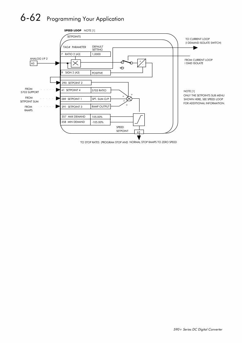
6-62 Programming Your Application
590+ Series DC Digital Converter
7 RATIO 2 (A3) 1,0000
9 SIGN 2 (A3)
290 SETPOINT 2
41 SETPOINT 4
289 SETPOINT 1
291 SETPOINT 3
357 MAX DEMAND
358 MIN DEMAND
POSITIVE
5703 RATIO
SPT. SUM O/P
RAMP OUTPUT
105.00%
-105.00%
63
+
+
+
+
+-
FROM5703 SUPPORT
FROMSETPOINT SUM
FROMRAMPS
A3
ANALOG I/P 2
TO STOP RATES (PROGRAM STOP AND NORMAL STOP RAMPS TO ZERO SPEED
NOTE [1]
ONLY THE SETPOINTS SUB MENUSHOWN HERE, SEE SPEED LOOPFOR ADDITIONAL INFORMATION.
TAG# PARAMETER DEFAULTSETTING
SETPOINTS
SPEED LOOP
TO CURRENT LOOP(I DEMAND ISOLATE SWITCH)
FROM CURRENT LOOPI DMD ISOLATE
SPEEDSETPOINT
NOTE [1]
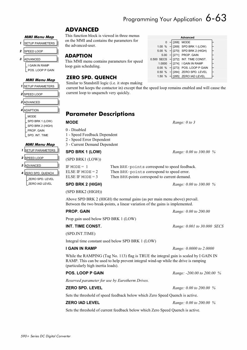
Programming Your Application 6-63
590+ Series DC Digital Converter
ADVANCEDThis function block is viewed in three menuson the MMI and contains the parameters forthe advanced-user.
ADAPTIONThis MMI menu contains parameters for speedloop gain scheduling.
ZERO SPD. QUENCHSimilar to Standstill logic (i.e. it stops makingcurrent but keeps the contactor in) except that the speed loop remains enabled and will cause thecurrent loop to unquench very quickly.
Advanced0 – [268] MODE –
1.00 % – [269] SPD BRK 1 (LOW) –5.00 % – [270] SPD BRK 2 (HIGH) –
5.00 – [271] PROP. GAIN –0.500 SECS – [272] INT. TIME CONST. –
1.0000 – [274] I GAIN IN RAMP –0.00 % – [273] POS. LOOP P GAIN –0.50 % – [284] ZERO SPD. LEVEL –1.50 % – [285] ZERO IAD LEVEL –
MMI Menu Map
1 SETUP PARAMETERS
2 SPEED LOOP
3 ADVANCED
I GAIN IN RAMPPOS. LOOP P GAIN
MMI Menu Map
1 SETUP PARAMETERS
2 SPEED LOOP
3 ADVANCED
4 ADAPTION
MODESPD BRK 1 (LOW)SPD BRK 2 (HIGH)PROP. GAINSPD. INT. TIME
MMI Menu Map 1 SETUP PARAMETERS
2 SPEED LOOP
3 ADVANCED
4 ZERO SPD. QUENCH
ZERO SPD. LEVELZERO IAD LEVEL
Parameter DescriptionsMODE Range: 0 to 3
0 - Disabled1 - Speed Feedback Dependent2 - Speed Error Dependent3 - Current Demand Dependent
SPD BRK 1 (LOW) Range: 0.00 to 100.00 %
(SPD BRK1 (LOW))
IF MODE = 1 Then BRK-points correspond to speed feedback.ELSE IF MODE = 2 Then BRK-points correspond to speed error.ELSE IF MODE = 3 Then BRK-points correspond to current demand.
SPD BRK 2 (HIGH) Range: 0.00 to 100.00 %
(SPD BRK2 (HIGH))
Above SPD BRK 2 (HIGH) the normal gains (as per main menu above) prevail.Between the two break-points, a linear variation of the gains is implemented.
PROP. GAIN Range: 0.00 to 200.00
Prop gain used below SPD BRK 1 (LOW)
INT. TIME CONST. Range: 0.001 to 30.000 SECS
(SPD.INT.TIME)
Integral time constant used below SPD BRK 1 (LOW)
I GAIN IN RAMP Range: 0.0000 to 2.0000
While the RAMPING (Tag No. 113) flag is TRUE the integral gain is scaled by I GAIN INRAMP. This can be used to help prevent integral wind-up while the drive is ramping(particularly high inertia loads).
POS. LOOP P GAIN Range: -200.00 to 200.00 %
Reserved parameter for use by Eurotherm Drives.
ZERO SPD. LEVEL Range: 0.00 to 200.00 %
Sets the threshold of speed feedback below which Zero Speed Quench is active.
ZERO IAD LEVEL Range: 0.00 to 200.00 %
Sets the threshold of current feedback below which Zero Speed Quench is active.
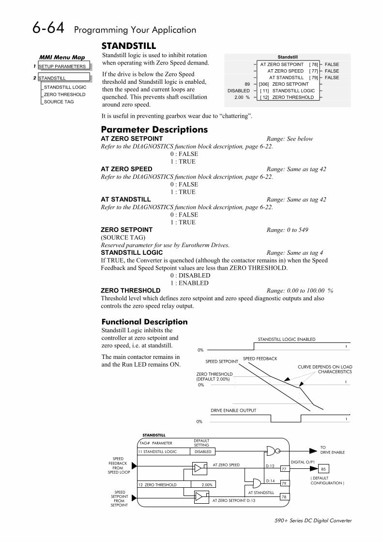
6-64 Programming Your Application
590+ Series DC Digital Converter
STANDSTILLStandstill logic is used to inhibit rotationwhen operating with Zero Speed demand.
If the drive is below the Zero Speedthreshold and Standstill logic is enabled,then the speed and current loops arequenched. This prevents shaft oscillationaround zero speed.
It is useful in preventing gearbox wear due to “chattering”.
Functional DescriptionStandstill Logic inhibits thecontroller at zero setpoint andzero speed, i.e. at standstill.
The main contactor remains inand the Run LED remains ON.
11 STANDSTILL LOGIC DISABLED
12 ZERO THRESHOLD 2.00%
SPEEDFEEDBACK
FROMSPEED LOOP
SPEEDSETPOINT
FROMSETPOINT
STANDSTILL
TAG# PARAMETERDEFAULT SETTING
78
77
79
AT ZERO SPEED
D:14
D:12
AT ZERO SETPOINT D:13
AT STANDSTILL
TO DRIVE ENABLE
DIGITAL O/P1
B5
( DEFAULTCONFIGURATION )
Standstill– AT ZERO SETPOINT [ 78] – FALSE– AT ZERO SPEED [ 77] – FALSE– AT STANDSTILL [ 79] – FALSE
89 – [306] ZERO SETPOINT –DISABLED – [ 11] STANDSTILL LOGIC –
2.00 % – [ 12] ZERO THRESHOLD –
MMI Menu Map 1 SETUP PARAMETERS
2 STANDSTILL
STANDSTILL LOGICZERO THRESHOLDSOURCE TAG
Parameter DescriptionsAT ZERO SETPOINT Range: See belowRefer to the DIAGNOSTICS function block description, page 6-22.
0 : FALSE1 : TRUE
AT ZERO SPEED Range: Same as tag 42Refer to the DIAGNOSTICS function block description, page 6-22.
0 : FALSE1 : TRUE
AT STANDSTILL Range: Same as tag 42Refer to the DIAGNOSTICS function block description, page 6-22.
0 : FALSE1 : TRUE
ZERO SETPOINT Range: 0 to 549(SOURCE TAG)Reserved parameter for use by Eurotherm Drives.STANDSTILL LOGIC Range: Same as tag 4If TRUE, the Converter is quenched (although the contactor remains in) when the SpeedFeedback and Speed Setpoint values are less than ZERO THRESHOLD.
0 : DISABLED1 : ENABLED
ZERO THRESHOLD Range: 0.00 to 100.00 %Threshold level which defines zero setpoint and zero speed diagnostic outputs and alsocontrols the zero speed relay output.
0%
STANDSTILL LOGIC ENABLED
0%
SPEED SETPOINTSPEED FEEDBACK
ZERO THRESHOLD(DEFAULT 2.00%)
CURVE DEPENDS ON LOADCHARACERISTICS
0%
DRIVE ENABLE OUTPUT
t
t
t
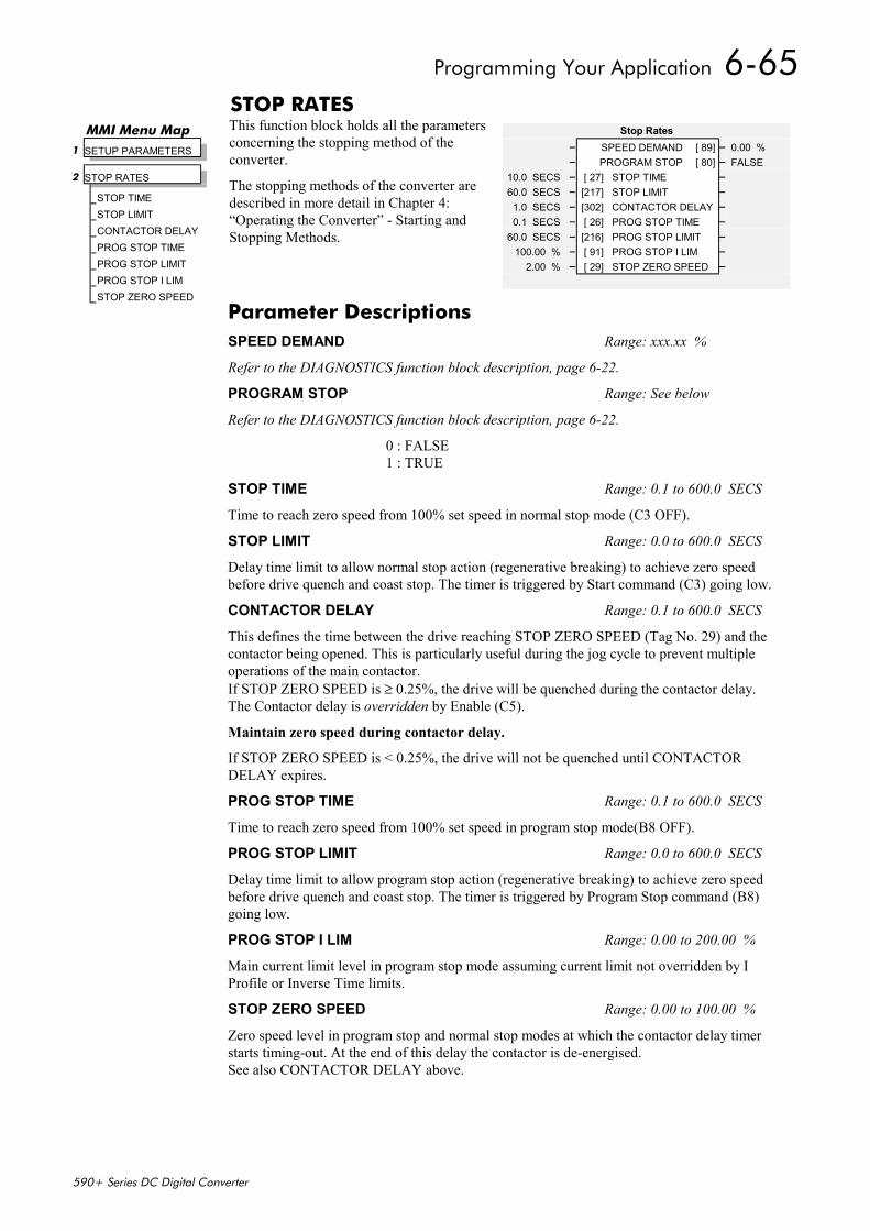
Programming Your Application 6-65
590+ Series DC Digital Converter
STOP RATESThis function block holds all the parametersconcerning the stopping method of theconverter.
The stopping methods of the converter aredescribed in more detail in Chapter 4:“Operating the Converter” - Starting andStopping Methods.
Stop Rates– SPEED DEMAND [ 89] – 0.00 %– PROGRAM STOP [ 80] – FALSE
10.0 SECS – [ 27] STOP TIME –60.0 SECS – [217] STOP LIMIT –1.0 SECS – [302] CONTACTOR DELAY –0.1 SECS – [ 26] PROG STOP TIME –
60.0 SECS – [216] PROG STOP LIMIT –100.00 % – [ 91] PROG STOP I LIM –
2.00 % – [ 29] STOP ZERO SPEED –
MMI Menu Map 1 SETUP PARAMETERS
2 STOP RATES
STOP TIMESTOP LIMITCONTACTOR DELAYPROG STOP TIMEPROG STOP LIMITPROG STOP I LIMSTOP ZERO SPEED
Parameter DescriptionsSPEED DEMAND Range: xxx.xx %
Refer to the DIAGNOSTICS function block description, page 6-22.
PROGRAM STOP Range: See below
Refer to the DIAGNOSTICS function block description, page 6-22.
0 : FALSE1 : TRUE
STOP TIME Range: 0.1 to 600.0 SECS
Time to reach zero speed from 100% set speed in normal stop mode (C3 OFF).
STOP LIMIT Range: 0.0 to 600.0 SECS
Delay time limit to allow normal stop action (regenerative breaking) to achieve zero speedbefore drive quench and coast stop. The timer is triggered by Start command (C3) going low.
CONTACTOR DELAY Range: 0.1 to 600.0 SECS
This defines the time between the drive reaching STOP ZERO SPEED (Tag No. 29) and thecontactor being opened. This is particularly useful during the jog cycle to prevent multipleoperations of the main contactor.If STOP ZERO SPEED is ≥ 0.25%, the drive will be quenched during the contactor delay.The Contactor delay is overridden by Enable (C5).
Maintain zero speed during contactor delay.
If STOP ZERO SPEED is < 0.25%, the drive will not be quenched until CONTACTORDELAY expires.
PROG STOP TIME Range: 0.1 to 600.0 SECS
Time to reach zero speed from 100% set speed in program stop mode(B8 OFF).
PROG STOP LIMIT Range: 0.0 to 600.0 SECS
Delay time limit to allow program stop action (regenerative breaking) to achieve zero speedbefore drive quench and coast stop. The timer is triggered by Program Stop command (B8)going low.
PROG STOP I LIM Range: 0.00 to 200.00 %
Main current limit level in program stop mode assuming current limit not overridden by IProfile or Inverse Time limits.
STOP ZERO SPEED Range: 0.00 to 100.00 %
Zero speed level in program stop and normal stop modes at which the contactor delay timerstarts timing-out. At the end of this delay the contactor is de-energised.See also CONTACTOR DELAY above.
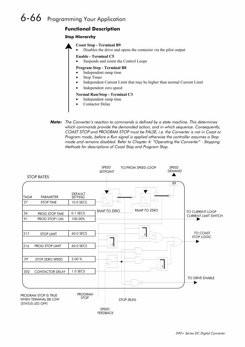
6-66 Programming Your Application
590+ Series DC Digital Converter
Functional Description
Stop Hierarchy
Coast Stop - Terminal B9• Disables the drive and opens the contactor via the pilot outputEnable - Terminal C5• Suspends and resets the Control LoopsProgram Stop - Terminal B8• Independent ramp time• Stop Timer• Independent Current Limit that may be higher than normal Current Limit• Independent zero speedNormal Run/Stop - Terminal C3• Independent ramp time• Contactor Delay
Note: The Converter’s reaction to commands is defined by a state machine. This determineswhich commands provide the demanded action, and in which sequence. Consequently,COAST STOP and PROGRAM STOP must be FALSE, i.e. the Converter is not in Coast orProgram mode, before a Run signal is applied otherwise the controller assumes a Stopmode and remains disabled. Refer to Chapter 4: “Operating the Converter” - StoppingMethods for descriptions of Coast Stop and Program Stop.
91
26
27
PROG STOP I LIM
PROG STOP TIME
STOP TIME
TAG# PARAMETER
100.00%
0.1 SECS
10.0 SECS
DEFAULTSETTING
STOP RATES
217 STOP LIMIT 60.0 SECS
216 PROG STOP LIMIT 60.0 SECS
29 STOP ZERO SPEED 2.00 %
302 CONTACTOR DELAY 1.0 SECS
89
RAMP TO ZERO RAMP TO ZERO
t
SPEEDSETPOINT
TO/FROM SPEED LOOP SPEEDDEMAND
TO CURRENT LOOPCURRENT LIMIT SWITCH
t
t
PROGRAMSTOP
SPEEDFEEDBACK
STOP (RUN)PROGRAM STOP IS TRUEWHEN TERMINAL B8 LOW(STATUS LED OFF)
TO COASTSTOP LOGIC
TO DRIVE ENABLE
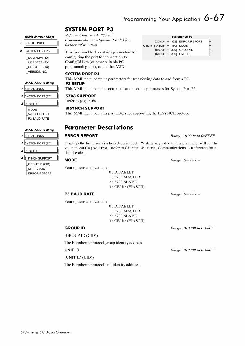
Programming Your Application 6-67
590+ Series DC Digital Converter
SYSTEM PORT P3Refer to Chapter 14: “SerialCommunications” - System Port P3 forfurther information.
This function block contains parameters forconfiguring the port for connection toConfigEd Lite (or other suitable PCprogramming tool), or another VSD.
SYSTEM PORT P3This MMI menu contains parameters for transferring data to and from a PC.P3 SETUPThis MMI menu contains communication set-up parameters for System Port P3.
5703 SUPPORTRefer to page 6-68.
BISYNCH SUPPORTThis MMI menu contains parameters for supporting the BISYNCH protocol.
MMI Menu Map
1 SERIAL LINKS
2 SYSTEM PORT P3
DUMP MMI (TX)UDP XFER (RX)UDP XFER (TX)VERSION NO.
System Port P30x00C0 – [332] ERROR REPORT –
CELite (EIASCII) – [130] MODE –0x0000 – [329] GROUP ID –0x0000 – [330] UNIT ID –
MMI Menu Map 1 SERIAL LINKS
2 SYSTEM PORT (P3)
3 P3 SETUP
MODE5703 SUPPORTP3 BAUD RATE
Parameter DescriptionsERROR REPORT Range: 0x0000 to 0xFFFF
Displays the last error as a hexadecimal code. Writing any value to this parameter will set thevalue to >00C0 (No Error). Refer to Chapter 14: “Serial Communications” - Reference for alist of codes.
MODE Range: See below
Four options are available:0 : DISABLED1 : 5703 MASTER2 : 5703 SLAVE3 : CELite (EIASCII)
P3 BAUD RATE Range: See below
Four options are available:0 : DISABLED1 : 5703 MASTER2 : 5703 SLAVE3 : CELite (EIASCII)
GROUP ID Range: 0x0000 to 0x0007
(GROUP ID (GID))
The Eurotherm protocol group identity address.
UNIT ID Range: 0x0000 to 0x000F
(UNIT ID (UID))
The Eurotherm protocol unit identity address.
MMI Menu Map 1 SERIAL LINKS
2 SYSTEM PORT (P3)
3 P3 SETUP
4 BISYNCH SUPPORT
GROUP ID (GID)UNIT ID (UID)ERROR REPORT
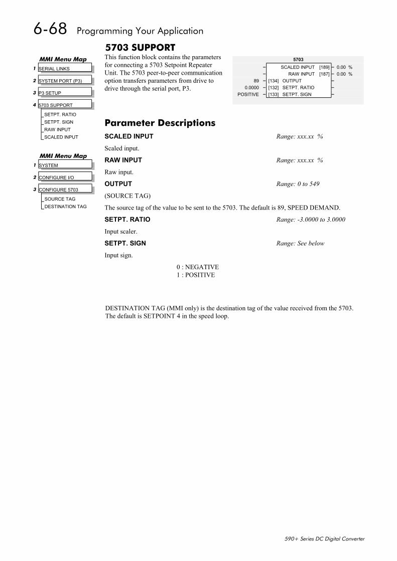
6-68 Programming Your Application
590+ Series DC Digital Converter
5703 SUPPORTThis function block contains the parametersfor connecting a 5703 Setpoint RepeaterUnit. The 5703 peer-to-peer communicationoption transfers parameters from drive todrive through the serial port, P3.
DESTINATION TAG (MMI only) is the destination tag of the value received from the 5703.The default is SETPOINT 4 in the speed loop.
5703– SCALED INPUT [189] – 0.00 %– RAW INPUT [187] – 0.00 %
89 – [134] OUTPUT –0.0000 – [132] SETPT. RATIO –
POSITIVE – [133] SETPT. SIGN –
MMI Menu Map 1 SERIAL LINKS
2 SYSTEM PORT (P3)
3 P3 SETUP
4 5703 SUPPORT
SETPT. RATIOSETPT. SIGNRAW INPUTSCALED INPUT
Parameter DescriptionsSCALED INPUT Range: xxx.xx %
Scaled input.
RAW INPUT Range: xxx.xx %
Raw input.
OUTPUT Range: 0 to 549
(SOURCE TAG)
The source tag of the value to be sent to the 5703. The default is 89, SPEED DEMAND.
SETPT. RATIO Range: -3.0000 to 3.0000
Input scaler.
SETPT. SIGN Range: See below
Input sign.
0 : NEGATIVE1 : POSITIVE
MMI Menu Map 1 SYSTEM
2 CONFIGURE I/O
3 CONFIGURE 5703
SOURCE TAGDESTINATION TAG
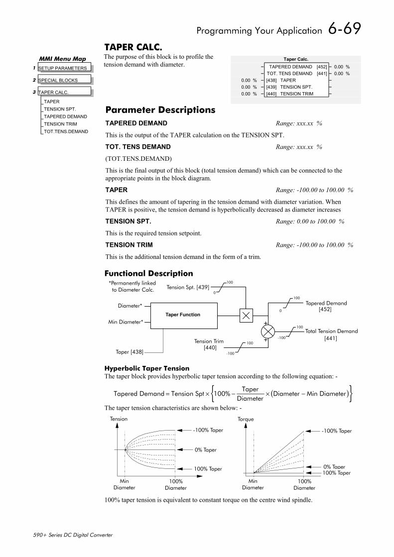
Programming Your Application 6-69
590+ Series DC Digital Converter
TAPER CALC.The purpose of this block is to profile thetension demand with diameter.
Functional Description
Taper Function
Tension Spt. [439]
Tapered DemandDiameter*
Min Diameter*
Tension Trim
Total Tension Demand[441]
[440]
*Permanently linked 100
0100
0
100
-100
100
-100
[452]
to Diameter Calc.
Taper [438]
Hyperbolic Taper TensionThe taper block provides hyperbolic taper tension according to the following equation: -
( ) Tapered Demand Tension Spt 100%Taper
DiameterDiameter Min Diameter= × − × −
The taper tension characteristics are shown below: -Tension
MinDiameter
100%Diameter
-100% Taper
100% Taper
0% Taper
Torque
MinDiameter
100%Diameter
-100% Taper
0% Taper100% Taper
100% taper tension is equivalent to constant torque on the centre wind spindle.
MMI Menu Map 1 SETUP PARAMETERS
2 SPECIAL BLOCKS
3 TAPER CALC.
TAPERTENSION SPT.TAPERED DEMANDTENSION TRIMTOT.TENS.DEMAND
Taper Calc.– TAPERED DEMAND [452] – 0.00 %– TOT. TENS DEMAND [441] – 0.00 %
0.00 % – [438] TAPER –0.00 % – [439] TENSION SPT. –0.00 % – [440] TENSION TRIM –
Parameter DescriptionsTAPERED DEMAND Range: xxx.xx %
This is the output of the TAPER calculation on the TENSION SPT.
TOT. TENS DEMAND Range: xxx.xx %
(TOT.TENS.DEMAND)
This is the final output of this block (total tension demand) which can be connected to theappropriate points in the block diagram.
TAPER Range: -100.00 to 100.00 %
This defines the amount of tapering in the tension demand with diameter variation. WhenTAPER is positive, the tension demand is hyperbolically decreased as diameter increases
TENSION SPT. Range: 0.00 to 100.00 %
This is the required tension setpoint.
TENSION TRIM Range: -100.00 to 100.00 %
This is the additional tension demand in the form of a trim.
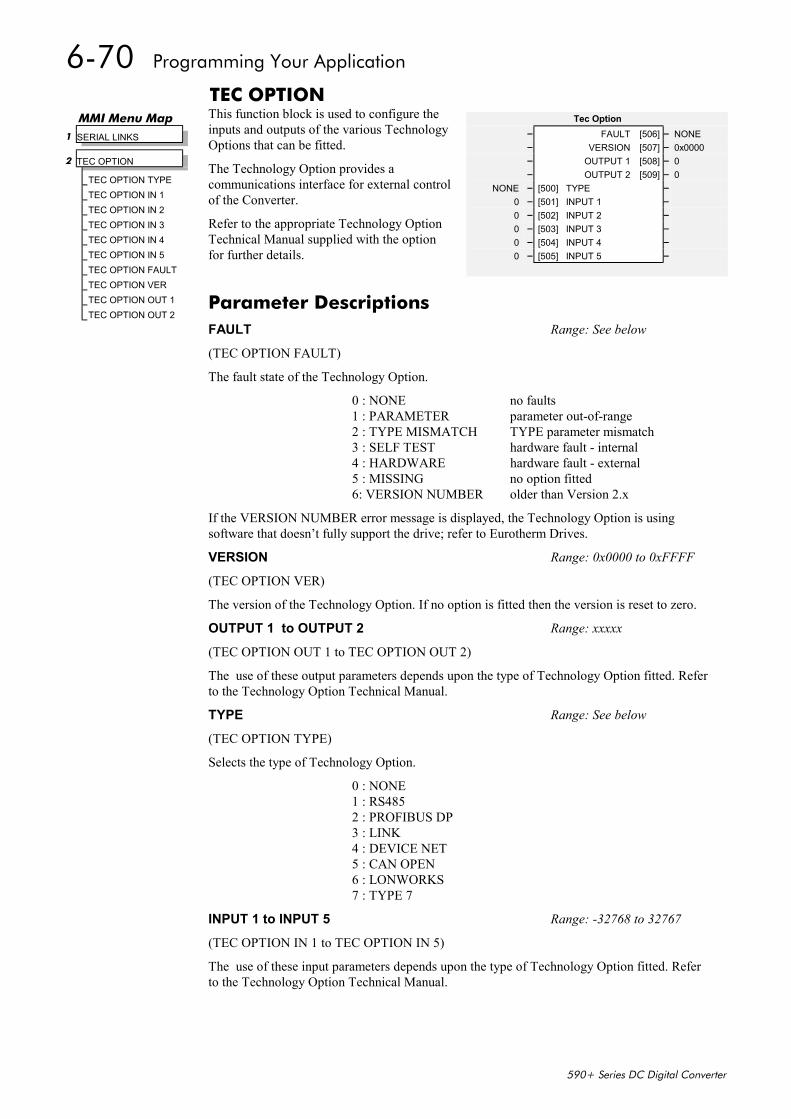
6-70 Programming Your Application
590+ Series DC Digital Converter
TEC OPTIONThis function block is used to configure theinputs and outputs of the various TechnologyOptions that can be fitted.
The Technology Option provides acommunications interface for external controlof the Converter.
Refer to the appropriate Technology OptionTechnical Manual supplied with the optionfor further details.
Tec Option– FAULT [506] – NONE– VERSION [507] – 0x0000– OUTPUT 1 [508] – 0– OUTPUT 2 [509] – 0
NONE – [500] TYPE –0 – [501] INPUT 1 –0 – [502] INPUT 2 –0 – [503] INPUT 3 –0 – [504] INPUT 4 –0 – [505] INPUT 5 –
MMI Menu Map 1 SERIAL LINKS
2 TEC OPTION
TEC OPTION TYPETEC OPTION IN 1TEC OPTION IN 2TEC OPTION IN 3TEC OPTION IN 4TEC OPTION IN 5TEC OPTION FAULTTEC OPTION VERTEC OPTION OUT 1TEC OPTION OUT 2
Parameter DescriptionsFAULT Range: See below
(TEC OPTION FAULT)
The fault state of the Technology Option.
0 : NONE no faults1 : PARAMETER parameter out-of-range2 : TYPE MISMATCH TYPE parameter mismatch3 : SELF TEST hardware fault - internal4 : HARDWARE hardware fault - external5 : MISSING no option fitted6: VERSION NUMBER older than Version 2.x
If the VERSION NUMBER error message is displayed, the Technology Option is usingsoftware that doesn’t fully support the drive; refer to Eurotherm Drives.
VERSION Range: 0x0000 to 0xFFFF
(TEC OPTION VER)
The version of the Technology Option. If no option is fitted then the version is reset to zero.
OUTPUT 1 to OUTPUT 2 Range: xxxxx
(TEC OPTION OUT 1 to TEC OPTION OUT 2)
The use of these output parameters depends upon the type of Technology Option fitted. Referto the Technology Option Technical Manual.
TYPE Range: See below
(TEC OPTION TYPE)
Selects the type of Technology Option.
0 : NONE1 : RS4852 : PROFIBUS DP3 : LINK4 : DEVICE NET5 : CAN OPEN6 : LONWORKS7 : TYPE 7
INPUT 1 to INPUT 5 Range: -32768 to 32767
(TEC OPTION IN 1 to TEC OPTION IN 5)
The use of these input parameters depends upon the type of Technology Option fitted. Referto the Technology Option Technical Manual.
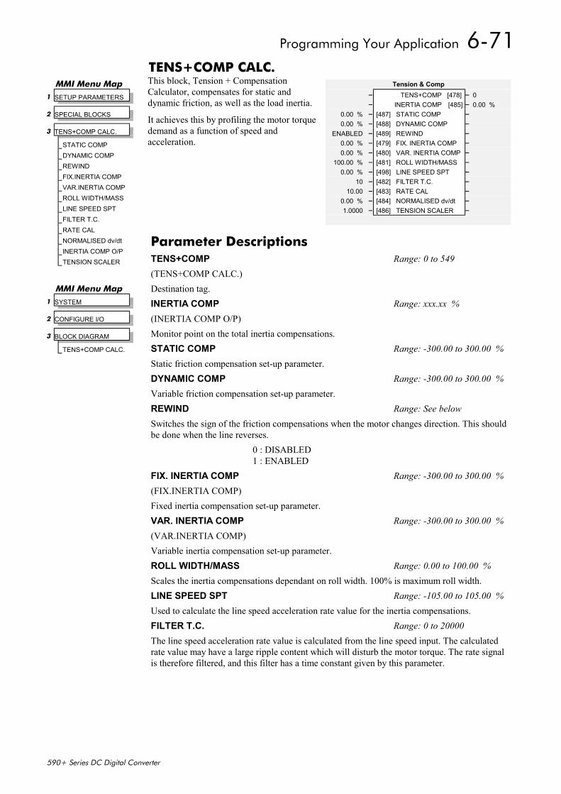
Programming Your Application 6-71
590+ Series DC Digital Converter
TENS+COMP CALC.This block, Tension + CompensationCalculator, compensates for static anddynamic friction, as well as the load inertia.
It achieves this by profiling the motor torquedemand as a function of speed andacceleration.
Tension & Comp– TENS+COMP [478] – 0– INERTIA COMP [485] – 0.00 %
0.00 % – [487] STATIC COMP –0.00 % – [488] DYNAMIC COMP –
ENABLED – [489] REWIND –0.00 % – [479] FIX. INERTIA COMP –0.00 % – [480] VAR. INERTIA COMP –
100.00 % – [481] ROLL WIDTH/MASS –0.00 % – [498] LINE SPEED SPT –
10 – [482] FILTER T.C. –10.00 – [483] RATE CAL –
0.00 % – [484] NORMALISED dv/dt –1.0000 – [486] TENSION SCALER –
MMI Menu Map 1 SETUP PARAMETERS
2 SPECIAL BLOCKS
3 TENS+COMP CALC.
STATIC COMPDYNAMIC COMPREWINDFIX.INERTIA COMPVAR.INERTIA COMPROLL WIDTH/MASSLINE SPEED SPTFILTER T.C.RATE CALNORMALISED dv/dtINERTIA COMP O/PTENSION SCALER
Parameter DescriptionsTENS+COMP Range: 0 to 549(TENS+COMP CALC.)Destination tag.INERTIA COMP Range: xxx.xx %(INERTIA COMP O/P)Monitor point on the total inertia compensations.STATIC COMP Range: -300.00 to 300.00 %Static friction compensation set-up parameter.DYNAMIC COMP Range: -300.00 to 300.00 %Variable friction compensation set-up parameter.REWIND Range: See belowSwitches the sign of the friction compensations when the motor changes direction. This shouldbe done when the line reverses.
0 : DISABLED1 : ENABLED
FIX. INERTIA COMP Range: -300.00 to 300.00 %(FIX.INERTIA COMP)Fixed inertia compensation set-up parameter.VAR. INERTIA COMP Range: -300.00 to 300.00 %(VAR.INERTIA COMP)Variable inertia compensation set-up parameter.ROLL WIDTH/MASS Range: 0.00 to 100.00 %Scales the inertia compensations dependant on roll width. 100% is maximum roll width.LINE SPEED SPT Range: -105.00 to 105.00 %Used to calculate the line speed acceleration rate value for the inertia compensations.FILTER T.C. Range: 0 to 20000The line speed acceleration rate value is calculated from the line speed input. The calculatedrate value may have a large ripple content which will disturb the motor torque. The rate signalis therefore filtered, and this filter has a time constant given by this parameter.
MMI Menu Map 1 SYSTEM
2 CONFIGURE I/O
3 BLOCK DIAGRAM
TENS+COMP CALC.

6-72 Programming Your Application
590+ Series DC Digital Converter
RATE CAL Range: -100.00 to 100.00Scales the inertia compensation acceleration rate value to 100% for the maximum line ramprate. This parameter should be set to the maximum line full speed ramp rate in Seconds. Theresultant rate value can be observed on the NORMALISED dv/dt value.Note - Inertia compensation does not work well for line ramp rates above 100 secs andtherefore this parameter is limited to 100.00.NORMALISED dv/dt Range: -300.00 to 300.00 %
1. RATE CAL = 0.00: Allows an externally generated rate signal to be used in place ofthe calculated value described above. This rate signal must be normalised to 100% formaximum line ramp rate. Useful for large line ramp rates (>100 Secs)
2. RATE CAL not 0.00: Allows the internally calculated rate value to be monitored.TENSION SCALER Range: -3.0000 to 3.0000Scales the Tension Demand which is directly connected from the Taper Calculator.
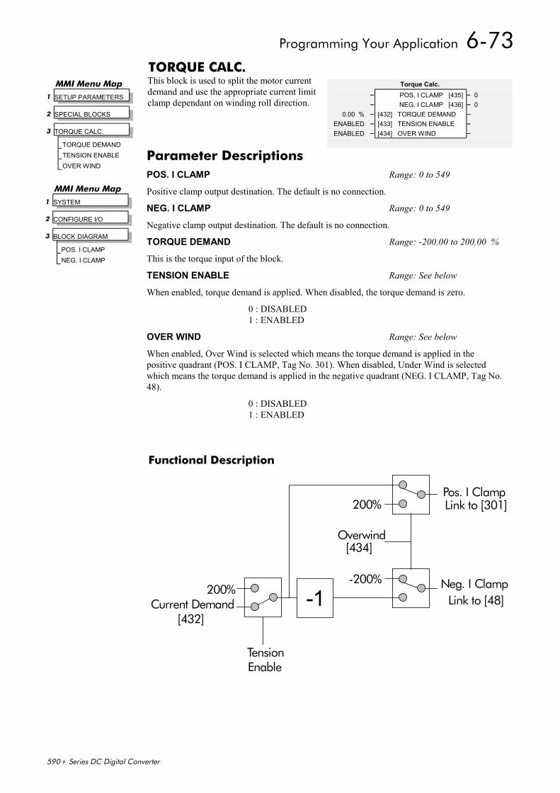
Programming Your Application 6-73
590+ Series DC Digital Converter
TORQUE CALC.This block is used to split the motor currentdemand and use the appropriate current limitclamp dependant on winding roll direction.
Functional Description
Pos. I Clamp
Neg. I Clamp 200%
TensionEnable
Overwind
-200%
200%
-1
[434]
Current Demand[432]
Link to [301]
Link to [48]
MMI Menu Map 1 SETUP PARAMETERS
2 SPECIAL BLOCKS
3 TORQUE CALC.
TORQUE DEMANDTENSION ENABLEOVER WIND
Torque Calc.– POS. I CLAMP [435] – 0– NEG. I CLAMP [436] – 0
0.00 % – [432] TORQUE DEMAND –ENABLED – [433] TENSION ENABLE –ENABLED – [434] OVER WIND –
MMI Menu Map 1 SYSTEM
2 CONFIGURE I/O
3 BLOCK DIAGRAM
POS. I CLAMPNEG. I CLAMP
Parameter DescriptionsPOS. I CLAMP Range: 0 to 549
Positive clamp output destination. The default is no connection.
NEG. I CLAMP Range: 0 to 549
Negative clamp output destination. The default is no connection.
TORQUE DEMAND Range: -200.00 to 200.00 %
This is the torque input of the block.
TENSION ENABLE Range: See below
When enabled, torque demand is applied. When disabled, the torque demand is zero.
0 : DISABLED1 : ENABLED
OVER WIND Range: See below
When enabled, Over Wind is selected which means the torque demand is applied in thepositive quadrant (POS. I CLAMP, Tag No. 301). When disabled, Under Wind is selectedwhich means the torque demand is applied in the negative quadrant (NEG. I CLAMP, Tag No.48).
0 : DISABLED1 : ENABLED
6-74 Programming Your Application
590+ Series DC Digital Converter
USER FILTERThis is an internal function block and doesnot appear as a menu on the MMI.
User Filter– OUTPUT [296] – 0.00 %
0.00 % – [295] INPUT –
Parameter DescriptionsINPUT Range: -300.00 to 300.00 %Reserved parameter for use by Eurotherm Drives.
OUTPUT Range: xxx.xx %Reserved parameter for use by Eurotherm Drives.

Trips and Fault Finding 7-1
590+ Series DC Digital Converter
7 TRIPS AND FAULT FINDING
Trips
What Happens when a Trip OccursWhen a trip occurs, the Converter’s power stage is immediately disabled causing the motor andload to coast to a stop. The trip is latched until action is taken to reset it. This ensures that tripsdue to transient conditions are captured and the Converter is disabled, even when the originalcause of the trip is no longer present.
Converter IndicationsIf a trip condition is detected the unit displays and performs the following actions.
1. The HEALTH LED goes out indicating a Trip condition has occurred. (Investigate, find andremove the cause of the trip.)
2. Terminal B6 (Healthy) goes low (0V).
Operator Station IndicationsIf a trip condition is detected the MMI displays and performs the following actions.
1. The HEALTH LED goes out indicating a Trip condition has occurred. The MMI displaysthe activated alarm. (Investigate, find and remove the cause of the trip.)
2. Terminal B6 (Healthy) goes low (0V).
3. The alarm message(s) can be acknowledged by pressing the E key, however, the unit willnot restart at this point.
Resetting a Trip ConditionAll trips must be reset before the Converter can be re-enabled. A trip can only be reset once thetrip condition is no longer active, i.e. a trip due to a heatsink over-temperature will not reset untilthe temperature is below the trip level.
Note: More than one trip can be active at any time. For example, it is possible for both theHEATSINK TRIP and the OVERVOLTS (VA) trips to be active. Alternatively it is possible forthe Converter to trip due to a FIELD OVER I error and then for the HEATSINK TRIP trip tobecome active after the Converter has stopped (this may occur due to the thermal timeconstant of the heatsink).
You can reset the trip(s) in one of two ways:
1. Power-up, or remove and re-apply the auxiliary power supply.
2. Stop and start the converter, i.e. remove and re-apply the Start/Run signal (terminal C3 or C4,or the STOP and RUN keys on the MMI).
Success is indicated by the HEALTH LED (on the unit or MMI) illuminating. The MMI willreturn to its original display.

7-2 Trips and Fault Finding
590+ Series DC Digital Converter
Fault Finding
ProblemProblemProblemProblem Possible CausePossible CausePossible CausePossible Cause RemedyRemedyRemedyRemedy
Converter will notpower-up
Fuse blown Check supply details, replace withcorrect fuse.
Check Product Code against Model No.
Faulty cabling Check all connections are correct andsecure.
Check cable continuity
Converter fuse keepsblowing
Faulty cabling or connectionswrong
Check for problem and rectify beforereplacing with correct fuse
Faulty Converter Contact Eurotherm Drives
Cannot obtainHEALTH state
Incorrect or no supplyavailable
Check supply details
Motor will not run atswitch on
Motor jammed Stop the Converter and clear the jam
Motor runs and stops Motor becomes jammed Stop the Converter and clear the jam
Motor runs at fullspeed only
Reversed tachogenerator oropen circuit tachogenerator
Check tachogenerator connections
Open circuit speed referencepotentiometer
Check terminal
Table 7-1 Fault Finding
Alarm MessagesWhen a trip occurs an alarm message is displayed on the MMI, andinformation about the trip is stored in the ALARM STATUS menu.
The alarm message and the LAST ALARM parameter are displayed inthe selected language of the MMI.
The HEALTH STORE and HEALTH WORD parameters display information as hexadecimalvalues, or the sum of the hexadecimal values when more than one alarm is active. Thus theunique value can represent one or more alarms.
Note: Hexadecimal refers to the common practice of counting to the base of 16 in computingrather than the base of 10. The sixteen `numbers’ used being 0 to 9, A to F. Thus an 8bit byte is represented by two characters in the range 00 to FF, while a 16 bit word isrepresented by four characters in the range 0000 to FFFF.
LAST ALARM(Tag 528). This display shows the last alarm message to have been displayed. To reset theparameter simply press the (DOWN) key to clear the alarm. Alternatively, you can switch theauxiliary supply off and on, causing NO ACTIVE ALARMS to be displayed.
HEALTH WORD(Tag 115).This parameter is used to continuously monitor the status of the Converter. As alarmsare added or removed, the display will immediately update to show the hexadecimal sum of thesealarms.
The value reverts to 0x0000 when the Start (C3) input is raised (+24V), and when no tripcondition is present.
HEALTH STORE(Tag 116).This displays the hexadecimal value of the first (or only) alarm to occur causing thetrip condition.
The display reverts to 0x0000 when the Start (C3) input is raised (+24V).
MMI Menu Map
1 ALARM STATUS
LAST ALARMHEALTH WORDHEALTH STORE
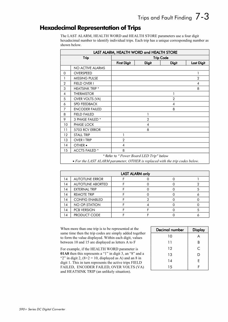
Trips and Fault Finding 7-3
590+ Series DC Digital Converter
Hexadecimal Representation of TripsThe LAST ALARM, HEALTH WORD and HEALTH STORE parameters use a four digithexadecimal number to identify individual trips. Each trip has a unique corresponding number asshown below.
LAST ALARM, HEALTH WORD and HEALTH STORELAST ALARM, HEALTH WORD and HEALTH STORELAST ALARM, HEALTH WORD and HEALTH STORELAST ALARM, HEALTH WORD and HEALTH STORETripTripTripTrip Trip CodeTrip CodeTrip CodeTrip Code
First DigitFirst DigitFirst DigitFirst Digit DigitDigitDigitDigit DigitDigitDigitDigit Last DigitLast DigitLast DigitLast DigitNO ACTIVE ALARMS
0 OVERSPEED 11 MISSING PULSE 22 FIELD OVER I 43 HEATSINK TRIP * 84 THERMISTOR 15 OVER VOLTS (VA) 26 SPD FEEDBACK 47 ENCODER FAILED 88 FIELD FAILED 19 3 PHASE FAILED * 210 PHASE LOCK 411 5703 RCV ERROR 812 STALL TRIP 113 OVER I TRIP 214 OTHER • 4
15 ACCTS FAILED * 8
* Refer to “ Power Board LED Trip” below • For the LAST ALARM parameter, OTHER is replaced with the trip codes below.
LAST ALARM onlyLAST ALARM onlyLAST ALARM onlyLAST ALARM only14 AUTOTUNE ERROR F 0 0 114 AUTOTUNE ABORTED F 0 0 214 EXTERNAL TRIP F 0 0 514 REMOTE TRIP F 0 0 614 CONFIG ENABLED F 2 0 014 NO OP-STATION F 4 0 014 PCB VERSION F F 0 514 PRODUCT CODE F F 0 6
When more than one trip is to be represented at thesame time then the trip codes are simply added togetherto form the value displayed. Within each digit, valuesbetween 10 and 15 are displayed as letters A to F
For example, if the HEALTH WORD parameter is01A8 then this represents a “1” in digit 3, an “8” and a“2” in digit 2, (8+2 = 10, displayed as A) and an 8 indigit 1. This in turn represents the active trips FIELDFAILED, ENCODER FAILED, OVER VOLTS (VA)and HEATSINK TRIP (an unlikely situation).
Decimal numberDecimal numberDecimal numberDecimal number DisplayDisplayDisplayDisplay
10 A
11 B
12 C
13 D
14 E
15 F
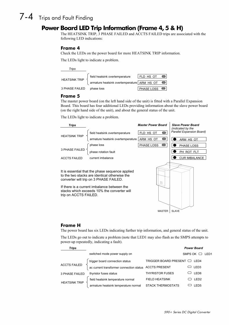
7-4 Trips and Fault Finding
590+ Series DC Digital Converter
Power Board LED Trip Information (Frame 4, 5 & H)The HEATSINK TRIP, 3 PHASE FAILED and ACCTS FAILED trips are associated with thefollowing LED indications:
Frame 4Check the LEDs on the power board for more HEATSINK TRIP information.
The LEDs light to indicate a problem.
FLD HS OT
ARM HS OT
PHASE LOSS
field heatsink overtemperature
armature heatsink overtemperature
phase loss
HEATSINK TRIP
3 PHASE FAILED
Trips
Frame 5The master power board (on the left hand side of the unit) is fitted with a Parallel ExpansionBoard. This board has four additional LEDs providing information about the slave power board(on the right hand side of the unit), and about the general status of the unit.
The LEDs light to indicate a problem.
Frame HThe power board has six LEDs indicating further trip information, and general status of the unit.
The LEDs go out to indicate a problem (note that LED1 may also flash as the SMPS attempts topower-up repeatedly, indicating a fault).
FIELD HEATSINK
STACK THERMOSTATS
field heatsink temperature normal
armature heatsink temperature normalHEATSINK TRIP
3 PHASE FAILED
Trips
TRIGGER BOARD PRESENT
ACCTS PRESENT
THYRISTOR FUSES
LED2
LED5
LED4
LED3
LED6
SMPS OK LED1
thyristor fuses status
ac current transformer connection status
trigger board connection status
switched mode power supply on
ACCTS FAILED
Power Board
FLD HS OT
ARM HS OT
PHASE LOSS
field heatsink overtemperature
armature heatsink overtemperature
phase loss
HEATSINK TRIP
3 PHASE FAILED
Trips
ARM HS OT
PHASE LOSS
PH ROT FLT
CUR IMBALANCE
Master Power Board Slave Power Board
phase rotation fault
current imbalanceACCTS FAILED
(indicated by the
MASTER SLAVE
It is essential that the phase sequence appliedto the two stacks are identical otherwise theconverter will trip on 3 PHASE FAILED.
If there is a current imbalance between thestacks which exceeds 10% the converter willtrip on ACCTS FAILED.
Parallel Expansion Board)

Trips and Fault Finding 7-5
590+ Series DC Digital Converter
Using the MMI to Manage TripsTrip MessagesMost of the alarms have a delay timer so that the Converter only trips if the condition persists forthe whole of the delay period.
If the Converter trips, then the display immediately shows a message indicating the reason for thetrip. The possible trip messages are given in the table below.
Trip Message and MeaningTrip Message and MeaningTrip Message and MeaningTrip Message and Meaning Possible Reason for TripPossible Reason for TripPossible Reason for TripPossible Reason for Trip
OVERSPEED
Motor overspeed - the speed feedbacksignal has exceeded 125% of ratedspeed.
Badly adjusted speed loop (alarm only operates withencoder or armature volts feedback selected)
Alarm time delay : 0.1 seconds
MISSING PULSE
A missing pulse from the 6-pulsearmature current waveform. Trips whenthe motor loading exceeds 1.5 times theDISCONTINUOUS parameter value.
Firing plug failure
Connection failure
Alarm time delay : 60 seconds
FIELD OVER I
The motor field current has exceeded120% of the calibrated value
Regulator failure
Badly tuned control loop (alarm only operates withfield current control mode selected)
Alarm time delay : 15 seconds
HEATSINK TRIP
The Converter heatsink temperature istoo high
The ambient air temperature is too high
Poor ventilation or spacing between Converters
Fan failure, check fuse on power board, wrongrotation (models above 70A bridge rating)
Blocked ventilation slots
Clogged air filters
Excessive armature current - nominal armaturecurrent on motor nameplate should be checkedagainst the current calibration for the Converter.
Note: The stack must be allowed to cool inorder to re-start the Converter.
Alarm time delay : 0.75 seconds
THERMISTOR
The motor temperature is too high Inadequate ventilation
Blower failure -check for direction, clogged air filters(models above 70A bridge rating)
Excessive armature current - check nominal armaturecurrent on nameplate against current calibration)
Note: The motor must be allowed to cool inorder to re-start the Converter.
Alarm time delay : 15 seconds
OVER VOLTS (VA)
Motor armature voltage has exceeded120% of rated volts
Loose armature connection
Badly adjusted field voltage setting
Badly adjusted field current loop
Badly adjusted field-weakening bemf loop
Badly adjusted speed loop
Alarm time delay : 1.5 seconds
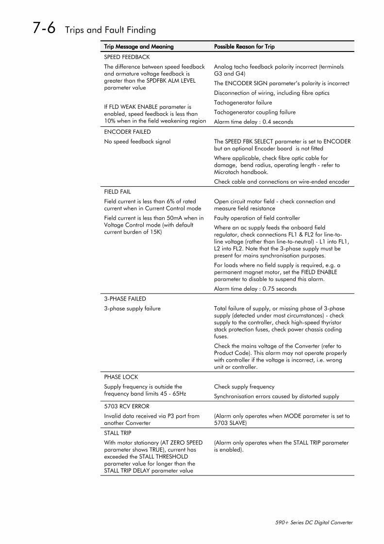
7-6 Trips and Fault Finding
590+ Series DC Digital Converter
Trip Message and MeaningTrip Message and MeaningTrip Message and MeaningTrip Message and Meaning Possible Reason for TripPossible Reason for TripPossible Reason for TripPossible Reason for Trip
SPEED FEEDBACK
The difference between speed feedbackand armature voltage feedback isgreater than the SPDFBK ALM LEVELparameter value
If FLD WEAK ENABLE parameter isenabled, speed feedback is less than10% when in the field weakening region
Analog tacho feedback polarity incorrect (terminalsG3 and G4)
The ENCODER SIGN parameter’s polarity is incorrect
Disconnection of wiring, including fibre optics
Tachogenerator failure
Tachogenerator coupling failure
Alarm time delay : 0.4 seconds
ENCODER FAILED
No speed feedback signal The SPEED FBK SELECT parameter is set to ENCODERbut an optional Encoder board is not fitted
Where applicable, check fibre optic cable fordamage, bend radius, operating length - refer toMicrotach handbook.
Check cable and connections on wire-ended encoder
FIELD FAIL
Field current is less than 6% of ratedcurrent when in Current Control mode
Field current is less than 50mA when inVoltage Control mode (with defaultcurrent burden of 15K)
Open circuit motor field - check connection andmeasure field resistance
Faulty operation of field controller
Where an ac supply feeds the onboard fieldregulator, check connections FL1 & FL2 for line-to-line voltage (rather than line-to-neutral) - L1 into FL1,L2 into FL2. Note that the 3-phase supply must bepresent for mains synchronisation purposes.
For loads where no field supply is required, e.g. apermanent magnet motor, set the FIELD ENABLEparameter to disable to suspend this alarm.
Alarm time delay : 0.75 seconds
3-PHASE FAILED
3-phase supply failure Total failure of supply, or missing phase of 3-phasesupply (detected under most circumstances) - checksupply to the controller, check high-speed thyristorstack protection fuses, check power chassis codingfuses.
Check the mains voltage of the Converter (refer toProduct Code). This alarm may not operate properlywith controller if the voltage is incorrect, i.e. wrongunit or controller.
PHASE LOCK
Supply frequency is outside thefrequency band limits 45 - 65Hz
Check supply frequency
Synchronisation errors caused by distorted supply
5703 RCV ERROR
Invalid data received via P3 port fromanother Converter
(Alarm only operates when MODE parameter is set to5703 SLAVE)
STALL TRIP
With motor stationary (AT ZERO SPEEDparameter shows TRUE), current hasexceeded the STALL THRESHOLDparameter value for longer than theSTALL TRIP DELAY parameter value
(Alarm only operates when the STALL TRIP parameteris enabled).
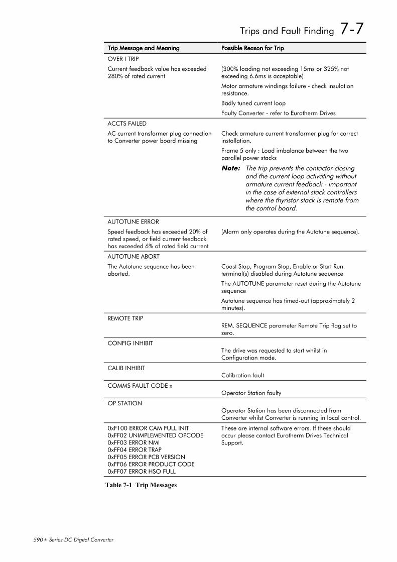
Trips and Fault Finding 7-7
590+ Series DC Digital Converter
Trip Message and MeaningTrip Message and MeaningTrip Message and MeaningTrip Message and Meaning Possible Reason for TripPossible Reason for TripPossible Reason for TripPossible Reason for Trip
OVER I TRIP
Current feedback value has exceeded280% of rated current
(300% loading not exceeding 15ms or 325% notexceeding 6.6ms is acceptable)
Motor armature windings failure - check insulationresistance.
Badly tuned current loop
Faulty Converter - refer to Eurotherm Drives
ACCTS FAILED
AC current transformer plug connectionto Converter power board missing
Check armature current transformer plug for correctinstallation.
Frame 5 only : Load imbalance between the twoparallel power stacks
Note: The trip prevents the contactor closingand the current loop activating withoutarmature current feedback - importantin the case of external stack controllerswhere the thyristor stack is remote fromthe control board.
AUTOTUNE ERROR
Speed feedback has exceeded 20% ofrated speed, or field current feedbackhas exceeded 6% of rated field current
(Alarm only operates during the Autotune sequence).
AUTOTUNE ABORT
The Autotune sequence has beenaborted.
Coast Stop, Program Stop, Enable or Start Runterminal(s) disabled during Autotune sequence
The AUTOTUNE parameter reset during the Autotunesequence
Autotune sequence has timed-out (approximately 2minutes).
REMOTE TRIPREM. SEQUENCE parameter Remote Trip flag set tozero.
CONFIG INHIBITThe drive was requested to start whilst inConfiguration mode.
CALIB INHIBITCalibration fault
COMMS FAULT CODE xOperator Station faulty
OP STATIONOperator Station has been disconnected fromConverter whilst Converter is running in local control.
0xF100 ERROR CAM FULL INIT0xFF02 UNIMPLEMENTED OPCODE0xFF03 ERROR NMI0xFF04 ERROR TRAP0xFF05 ERROR PCB VERSION0xFF06 ERROR PRODUCT CODE0xFF07 ERROR HSO FULL
These are internal software errors. If these shouldoccur please contact Eurotherm Drives TechnicalSupport.
Table 7-1 Trip Messages
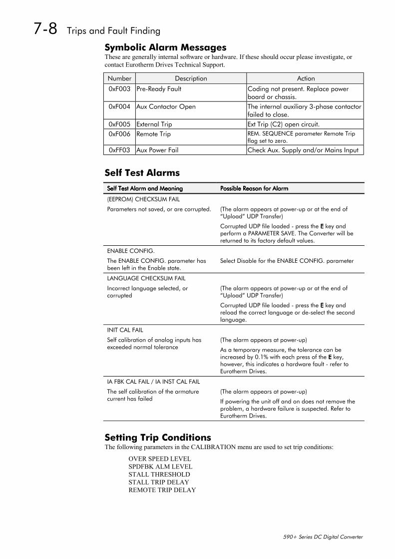
7-8 Trips and Fault Finding
590+ Series DC Digital Converter
Symbolic Alarm MessagesThese are generally internal software or hardware. If these should occur please investigate, orcontact Eurotherm Drives Technical Support.
Number Description Action
0xF003 Pre-Ready Fault Coding not present. Replace powerboard or chassis.
0xF004 Aux Contactor Open The internal auxiliary 3-phase contactorfailed to close.
0xF005 External Trip Ext Trip (C2) open circuit.0xF006 Remote Trip REM. SEQUENCE parameter Remote Trip
flag set to zero.
0xFF03 Aux Power Fail Check Aux. Supply and/or Mains Input
Self Test Alarms
Self Test Alarm and MeaningSelf Test Alarm and MeaningSelf Test Alarm and MeaningSelf Test Alarm and Meaning Possible Reason for AlarmPossible Reason for AlarmPossible Reason for AlarmPossible Reason for Alarm
(EEPROM) CHECKSUM FAIL
Parameters not saved, or are corrupted. (The alarm appears at power-up or at the end of“Upload” UDP Transfer)
Corrupted UDP file loaded - press the EEEE key andperform a PARAMETER SAVE. The Converter will bereturned to its factory default values.
ENABLE CONFIG.
The ENABLE CONFIG. parameter hasbeen left in the Enable state.
Select Disable for the ENABLE CONFIG. parameter
LANGUAGE CHECKSUM FAIL
Incorrect language selected, orcorrupted
(The alarm appears at power-up or at the end of“Upload” UDP Transfer)
Corrupted UDP file loaded - press the EEEE key andreload the correct language or de-select the secondlanguage.
INIT CAL FAIL
Self calibration of analog inputs hasexceeded normal tolerance
(The alarm appears at power-up)
As a temporary measure, the tolerance can beincreased by 0.1% with each press of the EEEE key,however, this indicates a hardware fault - refer toEurotherm Drives.
IA FBK CAL FAIL / IA INST CAL FAIL
The self calibration of the armaturecurrent has failed
(The alarm appears at power-up)
If powering the unit off and on does not remove theproblem, a hardware failure is suspected. Refer toEurotherm Drives.
Setting Trip ConditionsThe following parameters in the CALIBRATION menu are used to set trip conditions:
OVER SPEED LEVELSPDFBK ALM LEVELSTALL THRESHOLDSTALL TRIP DELAYREMOTE TRIP DELAY
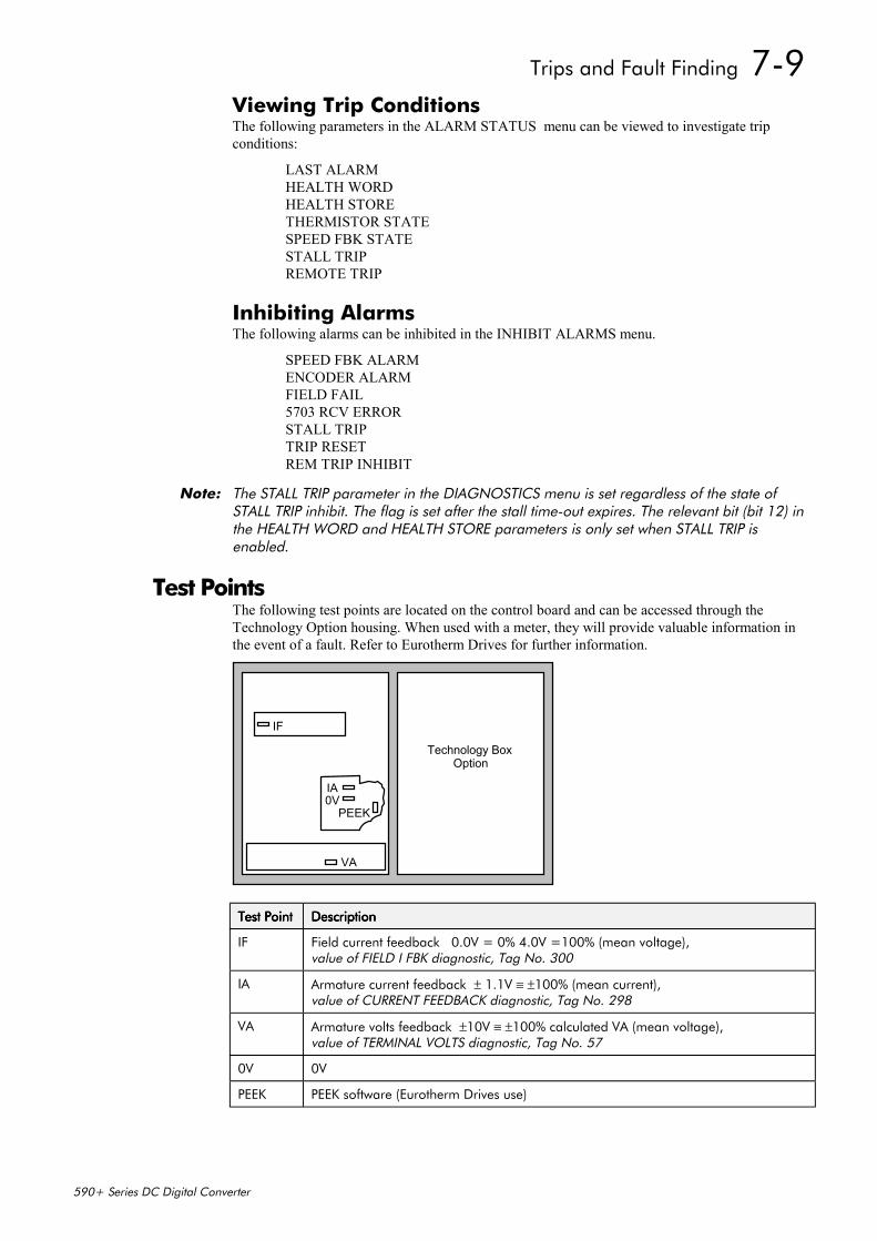
Trips and Fault Finding 7-9
590+ Series DC Digital Converter
Viewing Trip ConditionsThe following parameters in the ALARM STATUS menu can be viewed to investigate tripconditions:
LAST ALARMHEALTH WORDHEALTH STORETHERMISTOR STATESPEED FBK STATESTALL TRIPREMOTE TRIP
Inhibiting AlarmsThe following alarms can be inhibited in the INHIBIT ALARMS menu.
SPEED FBK ALARMENCODER ALARMFIELD FAIL5703 RCV ERRORSTALL TRIPTRIP RESETREM TRIP INHIBIT
Note: The STALL TRIP parameter in the DIAGNOSTICS menu is set regardless of the state ofSTALL TRIP inhibit. The flag is set after the stall time-out expires. The relevant bit (bit 12) inthe HEALTH WORD and HEALTH STORE parameters is only set when STALL TRIP isenabled.
Test PointsThe following test points are located on the control board and can be accessed through theTechnology Option housing. When used with a meter, they will provide valuable information inthe event of a fault. Refer to Eurotherm Drives for further information.
Technology BoxOption
IF
IA0V
VA
PEEK
Test PointTest PointTest PointTest Point DescriptionDescriptionDescriptionDescription
IF Field current feedback 0.0V = 0% 4.0V =100% (mean voltage),value of FIELD I FBK diagnostic, Tag No. 300
IA Armature current feedback ± 1.1V ≡ ±100% (mean current),value of CURRENT FEEDBACK diagnostic, Tag No. 298
VA Armature volts feedback ±10V ≡ ±100% calculated VA (mean voltage),value of TERMINAL VOLTS diagnostic, Tag No. 57
0V 0V
PEEK PEEK software (Eurotherm Drives use)

7-10 Trips and Fault Finding
590+ Series DC Digital Converter
Routine Maintenance and Repair 8-1
590+ Series DC Digital Converter
10 ROUTINE MAINTENANCE AND REPAIR
MaintenanceBecause of its solid state design, the 590+ Digital drive has few items requiring service ormaintenance. Service typically is a matter of replacing fuses, checking electrical contacts, andisolating problems in the overall system application.
Caution Service procedures must be performed by qualified personnel with an understanding ofthe dangers inherent in high voltage applications and the precautions necessary whenservicing industrial equipment. The customer is responsible for assessing the technical
competency of in-house service personnel.
Service ProceduresRequired Tools and EquipmentTools needed for routine service operations include basic hand tools — screwdrivers, wrenches,etc.
WARNING! Only qualified service personnel should attempt to repair or replace parts in the
590+.
Isolate the entire 590+drive from electrical power before attempting to work on it.
Preventive MaintenanceYou should perform regular preventive maintenance every six months to ensure long life andcontinued usefulness of the 590+. Keep the drive and its components clean, check auxiliary fansif fitted, and make sure connections and mounting bolts have not loosened from vibration.
The control and field wires can be checked by gently attempting pulling the wires out of theterminals. The terminals should hold the wires firmly in place.
All the remaining wires should be checked with a torque wrench. Refer to Chapter 11: TechnicalSpecifications - Termination Tightening Torque tables.
RepairThere are no user-serviceable components.
IMPORTANT: MAKE NO ATTEMPT TO REPAIR THE UNIT - RETURN IT TO EUROTHERM DRIVES.
Saving Your Application DataThe Converter retains saved settings during power-down. You can download and upload thisback into the repaired unit, if necessary. You may, depending upon your knowledge of the fault,attempt the back-up of your application data now, refer to Chapter 5: “The Operator Station” -Copying an Application.
If the fault clearly lies within the MMI, then return the unit for repair.
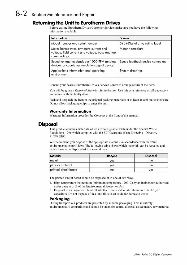
8-2 Routine Maintenance and Repair
590+ Series DC Digital Converter
Returning the Unit to Eurotherm DrivesBefore calling Eurotherm Drives Customer Service, make sure you have the followinginformation available:
InformationInformationInformationInformation SourceSourceSourceSource
Model number and serial number 590+Digital drive rating label
Motor horsepower, armature current andvoltage, field current and voltage, base and topspeed ratings
Motor nameplate
Speed voltage feedback per 1000 RPM (analogdevice), or counts per revolution(digital device)
Speed feedback device nameplate
Applications information and operatingenvironment
System drawings.
Contact your nearest Eurotherm Drives Service Centre to arrange return of the item.
You will be given a Returned Material Authorisation. Use this as a reference on all paperworkyou return with the faulty item.
Pack and despatch the item in the original packing materials; or at least an anti-static enclosure.Do not allow packaging chips to enter the unit.
Warranty InformationWarranty information precedes the Contents at the front of this manual.
DisposalThis product contains materials which are consignable waste under the Special WasteRegulations 1996 which complies with the EC Hazardous Waste Directive - Directive91/689/EEC.
We recommend you dispose of the appropriate materials in accordance with the validenvironmental control laws. The following table shows which materials can be recycled andwhich have to be disposed of in a special way.
MaterialMaterialMaterialMaterial RecycleRecycleRecycleRecycle DisposalDisposalDisposalDisposalmetal yes noplastics material yes noprinted circuit board no yes
The printed circuit board should be disposed of in one of two ways:1. High temperature incineration (minimum temperature 1200°C) by an incinerator authorised
under parts A or B of the Environmental Protection Act2. Disposal in an engineered land fill site that is licensed to take aluminium electrolytic
capacitors. Do not dispose of in a land fill site set aside for domestic waste.
PackagingDuring transport our products are protected by suitable packaging. This is entirelyenvironmentally compatible and should be taken for central disposal as secondary raw material.
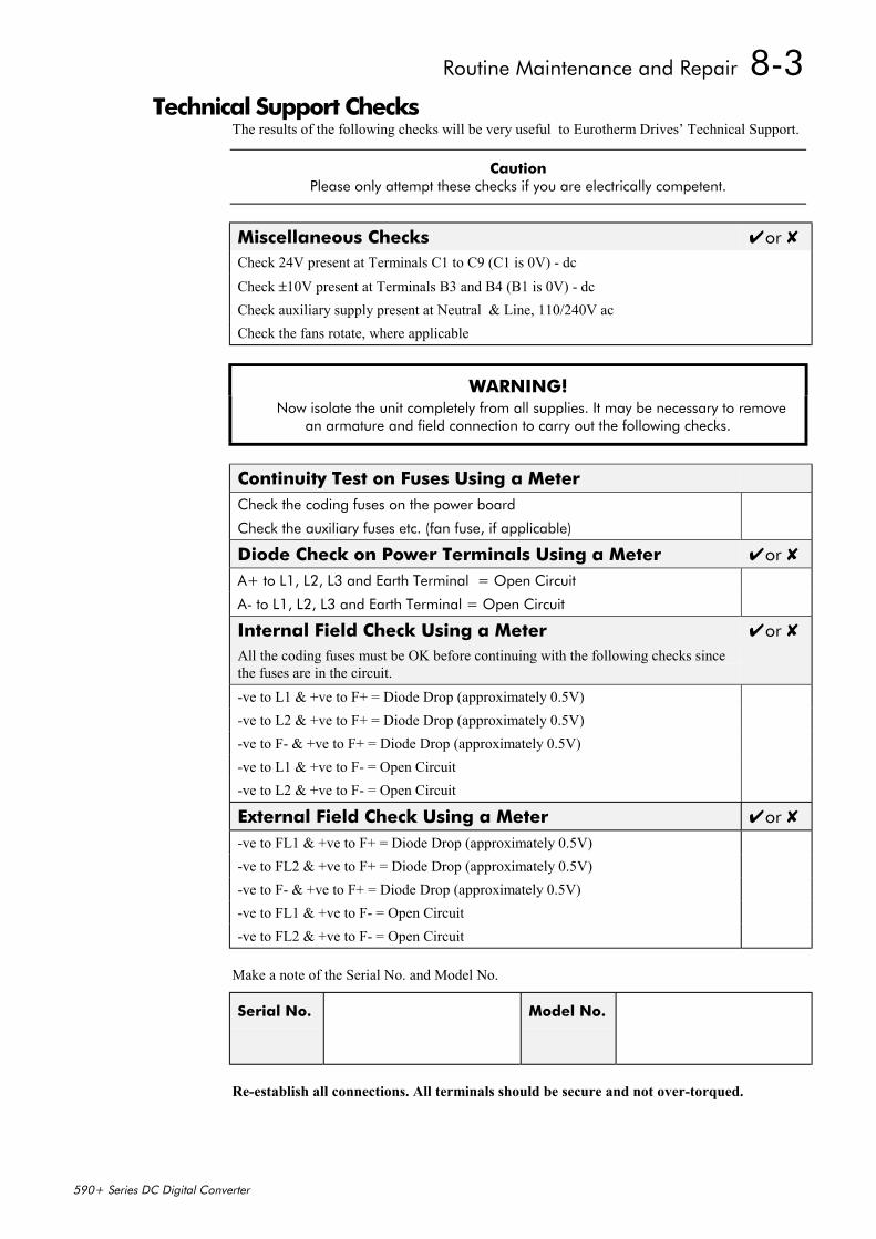
Routine Maintenance and Repair 8-3
590+ Series DC Digital Converter
Technical Support ChecksThe results of the following checks will be very useful to Eurotherm Drives’ Technical Support.
Caution Please only attempt these checks if you are electrically competent.
Miscellaneous Checks or Check 24V present at Terminals C1 to C9 (C1 is 0V) - dc
Check ±10V present at Terminals B3 and B4 (B1 is 0V) - dcCheck auxiliary supply present at Neutral & Line, 110/240V acCheck the fans rotate, where applicable
WARNING! Now isolate the unit completely from all supplies. It may be necessary to remove
an armature and field connection to carry out the following checks.
Continuity Test on Fuses Using a MeterCheck the coding fuses on the power board
Check the auxiliary fuses etc. (fan fuse, if applicable)
Diode Check on Power Terminals Using a Meter or A+ to L1, L2, L3 and Earth Terminal = Open Circuit
A- to L1, L2, L3 and Earth Terminal = Open Circuit
Internal Field Check Using a MeterAll the coding fuses must be OK before continuing with the following checks sincethe fuses are in the circuit.
or
-ve to L1 & +ve to F+ = Diode Drop (approximately 0.5V)-ve to L2 & +ve to F+ = Diode Drop (approximately 0.5V)-ve to F- & +ve to F+ = Diode Drop (approximately 0.5V)-ve to L1 & +ve to F- = Open Circuit-ve to L2 & +ve to F- = Open Circuit
External Field Check Using a Meter or -ve to FL1 & +ve to F+ = Diode Drop (approximately 0.5V)-ve to FL2 & +ve to F+ = Diode Drop (approximately 0.5V)-ve to F- & +ve to F+ = Diode Drop (approximately 0.5V)-ve to FL1 & +ve to F- = Open Circuit-ve to FL2 & +ve to F- = Open Circuit
Make a note of the Serial No. and Model No.
Serial No. Model No.
Re-establish all connections. All terminals should be secure and not over-torqued.
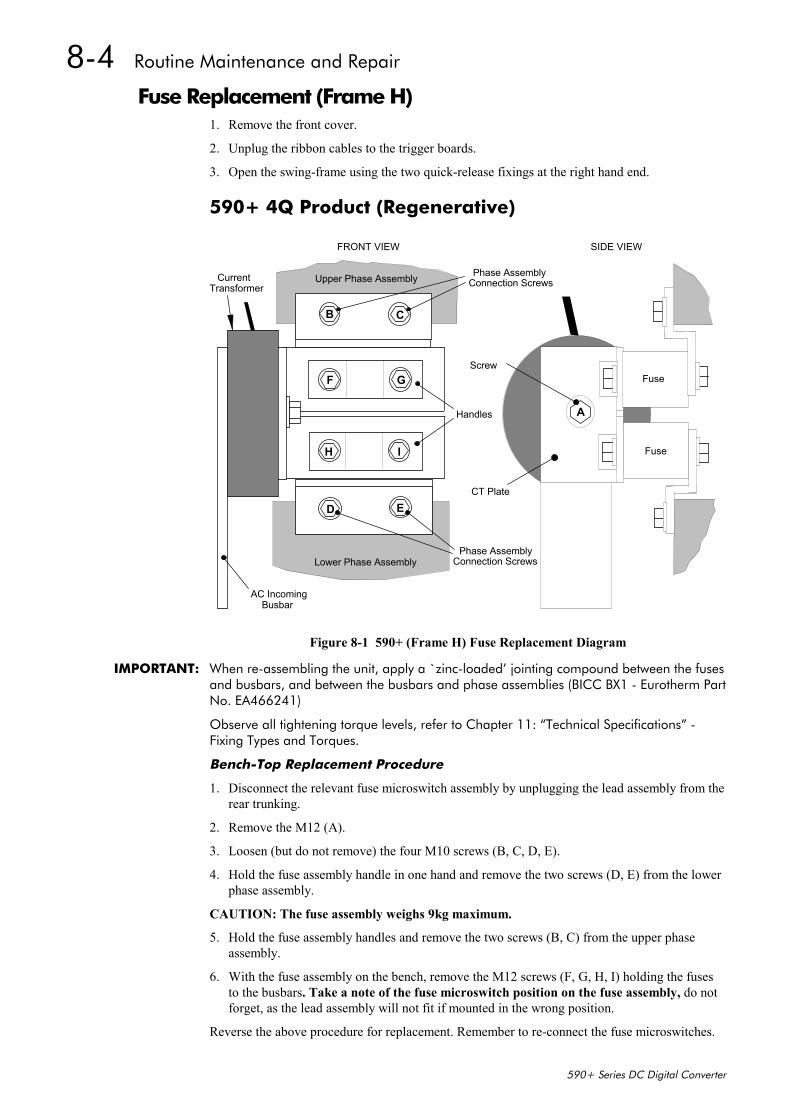
8-4 Routine Maintenance and Repair
590+ Series DC Digital Converter
Fuse Replacement (Frame H)1. Remove the front cover.
2. Unplug the ribbon cables to the trigger boards.
3. Open the swing-frame using the two quick-release fixings at the right hand end.
590+ 4Q Product (Regenerative)
Upper Phase Assembly
Lower Phase Assembly
CurrentTransformer
AC IncomingBusbar
Fuse
Phase AssemblyConnection Screws
Screw
A
B C
D E
Handles
FRONT VIEW SIDE VIEW
Phase AssemblyConnection Screws
Fuse
F G
H I
CT Plate
Figure 8-1 590+ (Frame H) Fuse Replacement Diagram
IMPORTANT: When re-assembling the unit, apply a `zinc-loaded’ jointing compound between the fusesand busbars, and between the busbars and phase assemblies (BICC BX1 - Eurotherm PartNo. EA466241)
Observe all tightening torque levels, refer to Chapter 11: “Technical Specifications” -Fixing Types and Torques.
Bench-Top Replacement Procedure
1. Disconnect the relevant fuse microswitch assembly by unplugging the lead assembly from therear trunking.
2. Remove the M12 (A).
3. Loosen (but do not remove) the four M10 screws (B, C, D, E).
4. Hold the fuse assembly handle in one hand and remove the two screws (D, E) from the lowerphase assembly.
CAUTION: The fuse assembly weighs 9kg maximum.
5. Hold the fuse assembly handles and remove the two screws (B, C) from the upper phaseassembly.
6. With the fuse assembly on the bench, remove the M12 screws (F, G, H, I) holding the fusesto the busbars. Take a note of the fuse microswitch position on the fuse assembly, do notforget, as the lead assembly will not fit if mounted in the wrong position.
Reverse the above procedure for replacement. Remember to re-connect the fuse microswitches.
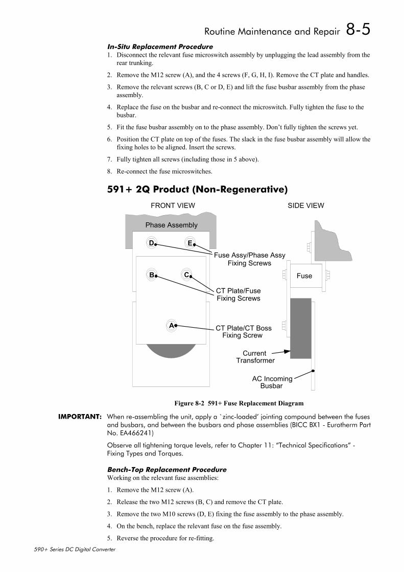
Routine Maintenance and Repair 8-5
590+ Series DC Digital Converter
In-Situ Replacement Procedure1. Disconnect the relevant fuse microswitch assembly by unplugging the lead assembly from the
rear trunking.
2. Remove the M12 screw (A), and the 4 screws (F, G, H, I). Remove the CT plate and handles.
3. Remove the relevant screws (B, C or D, E) and lift the fuse busbar assembly from the phaseassembly.
4. Replace the fuse on the busbar and re-connect the microswitch. Fully tighten the fuse to thebusbar.
5. Fit the fuse busbar assembly on to the phase assembly. Don’t fully tighten the screws yet.
6. Position the CT plate on top of the fuses. The slack in the fuse busbar assembly will allow thefixing holes to be aligned. Insert the screws.
7. Fully tighten all screws (including those in 5 above).
8. Re-connect the fuse microswitches.
591+ 2Q Product (Non-Regenerative)
D E
B C
A
Phase Assembly
CurrentTransformer
AC IncomingBusbar
Fuse
CT Plate/FuseFixing Screws
CT Plate/CT BossFixing Screw
FRONT VIEW
Fuse Assy/Phase AssyFixing Screws
SIDE VIEW
Figure 8-2 591+ Fuse Replacement Diagram
IMPORTANT: When re-assembling the unit, apply a `zinc-loaded’ jointing compound between the fusesand busbars, and between the busbars and phase assemblies (BICC BX1 - Eurotherm PartNo. EA466241)
Observe all tightening torque levels, refer to Chapter 11: “Technical Specifications” -Fixing Types and Torques.
Bench-Top Replacement ProcedureWorking on the relevant fuse assemblies:
1. Remove the M12 screw (A).
2. Release the two M12 screws (B, C) and remove the CT plate.
3. Remove the two M10 screws (D, E) fixing the fuse assembly to the phase assembly.
4. On the bench, replace the relevant fuse on the fuse assembly.
5. Reverse the procedure for re-fitting.
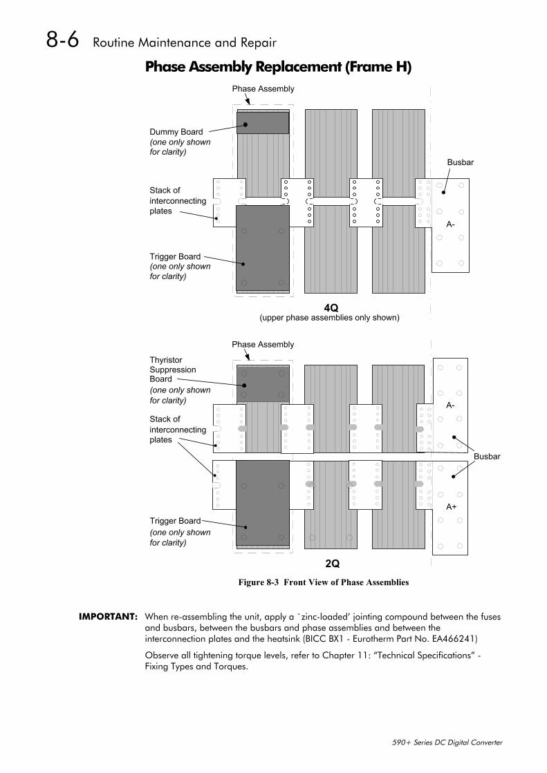
8-6 Routine Maintenance and Repair
590+ Series DC Digital Converter
Phase Assembly Replacement (Frame H)
Busbar
Phase Assembly
4Q
Busbar
Phase Assembly
Stack ofinterconnectingplates
2Q
A-
A+
A-
(upper phase assemblies only shown)
Trigger Board
Trigger Board
Thyristor
Dummy Board
Stack ofinterconnectingplates
SuppressionBoard
(one only shownfor clarity)
(one only shownfor clarity)
(one only shownfor clarity)
(one only shownfor clarity)
Figure 8-3 Front View of Phase Assemblies
IMPORTANT: When re-assembling the unit, apply a `zinc-loaded’ jointing compound between the fusesand busbars, between the busbars and phase assemblies and between theinterconnection plates and the heatsink (BICC BX1 - Eurotherm Part No. EA466241)
Observe all tightening torque levels, refer to Chapter 11: “Technical Specifications” -Fixing Types and Torques.

Routine Maintenance and Repair 8-7
590+ Series DC Digital Converter
Phase Assembly Removal Procedure
1. Referring to Figure 8-1 (590+) or Figure 8-2 (591+), remove the M12 screw (A). Undo thefour screws (B, C, D, E) which allows the CT plate and fuse assembly to be removed.
2. Unplug the thyristor gate leads and the heatsink overtemperature leads from the relevantphase assembly trigger board. Remove the same leads from the adjacent phase assembly orassemblies (this is necessary to gain complete access to the interconnecting plates.) If youare removing the phase assembly from a 591+ (2Q) product, also disconnect the thyristorsuppression lead from the trigger boards.
3. Remove the trigger board by releasing the four M6 Sems nuts fixing the PCB to theassembly. If you are working on a 590+ (4Q), remove the dummy trigger board, or if workingon a 591+ (2Q) remove the thyristor suppression board. Remove the air duct from the top ofthe phase assembly to gain access to the DC interconnection plates.Do not remove the trigger board support spacers.
4. Remove the DC interconnection plates between the phase assembly and its adjacentassemblies, either output terminals or phase assemblies.
5. If changing an upper phase assembly on a 590+ or 591+ remove the top baffle. This isachieved by pushing out the two end flaps of the plenum chamber and unclipping the topbaffle from the top cover baffle stops and the top of the phase assemblies. Remove thevertical baffles between phase assemblies.
6. If changing a lower phase assembly on a 590+, remove the lower air duct.
7. Remove the complete phase assembly by removing the four M6 Sems nuts at the top andbottom of the phase assembly.
Note: On the 591+ 2Q, the left hand screw retains the phase coding connection which shouldbe pushed to one side before lifting the phase assembly.
Phase Assembly Fitting Procedure1. Position the repaired or spare phase assembly on to the back panel spacer. (Remember to re-
connect the coding lead to the bottom of the phase assembly when working on a 591+ 2Q).
Check for correct orientation of the assembly. Fix in position with 4 x M6 Sems nuts andtighten to the correct torque level.
Refit the interconnecting plate stacks between the phase assemblies. A stack of three platesare used on a 1200 Amp unit, four on a 1700 Amp unit, five on a 2200 Amp unit and six on a2700 Amp unit. On a 4Q unit the plates interconnect both the upper and lower thyristors andadjacent phase assemblies. On the 2Q unit the plates interconnect adjacent phase assemblies.Tighten to the correct torque level.
Note: a) When fitting a spare phase assembly there may be some misalignment to the newphase where the interconnection plates do not fit easily. In this case, loosen the triggersupport spacers which will allow adjustment of the support bars. Fit the interconnectingplates and re-tighten all units, including spacers.
b) When re-assembling the interconnection plates it is important that a good electricalcontact is made between the plates and the aluminium heatsink. Apply a layer of `zinc-loaded’ jointing compound between the interconnection plates and the heatsink.
3. Refit the air duct on the phase assembly ensuring that the duct fits inside the side ducting ofthe phase assembly.
4. Refit the trigger board (thyristor suppression board or dummy board as appropriate) andsecure with the M6 Sems nuts.
5. Reconnect the gate leads, thermostat and suppression lead as necessary. The gate leadscannot be fitted incorrectly as they are polarised by the plugs.
6. Re-fit the top baffle (either plenum cover or lower 4Q air duct) and vertical baffles.
7. Replace the fuse.
8. Re-close the swing-frame.
9. Replace the trigger board connectors.
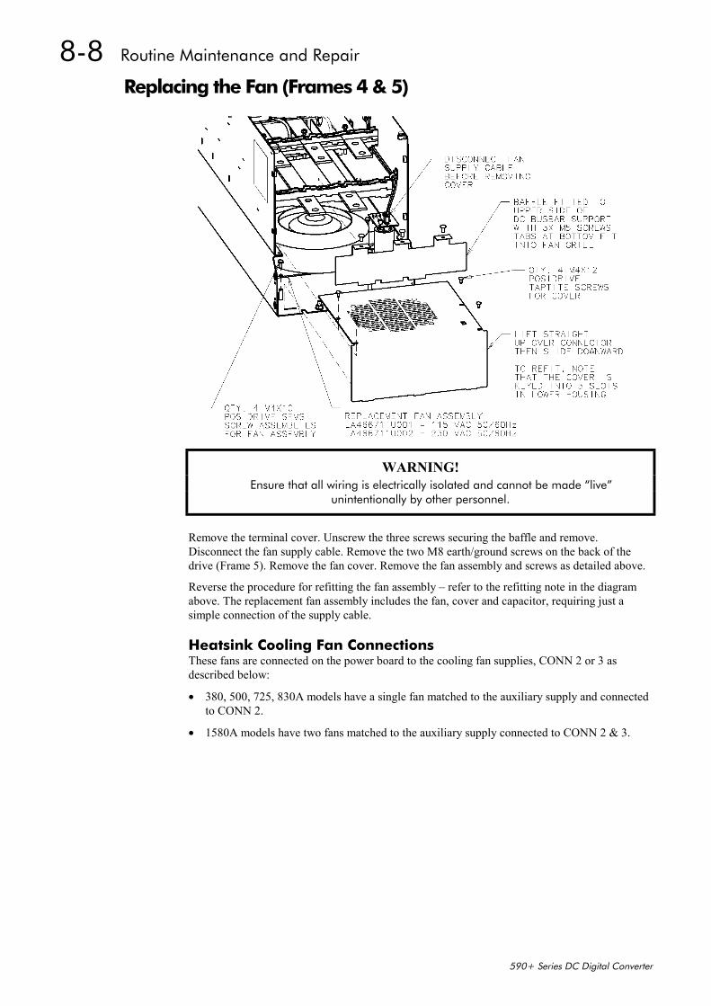
8-8 Routine Maintenance and Repair
590+ Series DC Digital Converter
Replacing the Fan (Frames 4 & 5)
WARNING! Ensure that all wiring is electrically isolated and cannot be made “live”
unintentionally by other personnel.
Remove the terminal cover. Unscrew the three screws securing the baffle and remove.Disconnect the fan supply cable. Remove the two M8 earth/ground screws on the back of thedrive (Frame 5). Remove the fan cover. Remove the fan assembly and screws as detailed above.
Reverse the procedure for refitting the fan assembly – refer to the refitting note in the diagramabove. The replacement fan assembly includes the fan, cover and capacitor, requiring just asimple connection of the supply cable.
Heatsink Cooling Fan ConnectionsThese fans are connected on the power board to the cooling fan supplies, CONN 2 or 3 asdescribed below:
• 380, 500, 725, 830A models have a single fan matched to the auxiliary supply and connectedto CONN 2.
• 1580A models have two fans matched to the auxiliary supply connected to CONN 2 & 3.
Control Loops 9-1
590+ Series DC Digital Converter
9 CONTROL LOOPS
Principle of OperationNote: Selection between Current Control or Speed Control (default) is
made by the I DMD ISOLATE (current demand isolate) parameterusing Digital I/P3 (Terminal C8). If ENABLED the Converteroperates as a current controller, and if DISABLED (the default) itoperates as a speed controller.
Current LoopThe current loop accepts a demand from either the speed loop, or directly from the plant, andforms an error signal which is the difference between demand and average value of feedback.The error signal is fed into a Proportional + Integral compensator which produces the output ofthe current loop, i.e. the firing angle signal.
In the Converter, the error signal is created in two different forms:
1. The average error is computed as the difference between demand and average value offeedback and fed into the Integral part of the P + I algorithm.
2. The instantaneous error is computed as the difference between demand and instantaneousvalue of feedback and is fed into the Proportional part of the P + I algorithm. This giveshigher transient performance since it does not contain any time lag, unlike the average whichhas a built-in lag of 1/6 of mains cycle. However, the average is the true measurement oftorque which is the objective of the current control and this is not affected by the small timelag in achieving zero steady-state error.
The firing angle signal is translated into a certain time delay from the mains zero cross point(obtained via a Phase-Lock-Loop) and this results in a firing command being issued to thethyristor stack every 1/6 of a mains cycle in steady-state.
Some special features of the current controller are discussed separately below.
Adaptive Current ControlThe gain of a thyristor 6-pulse converter (voltage-time area over firing angle) drops dramaticallyat discontinuous values of armature current. Therefore a gain boost is required in the currentcontroller to compensate for that.
In the Converter, this is handled by an adaptive algorithm which allows the current to follow thedemand in one step (firing) within the discontinuous region of operation.
Back EMF (BEMF) EstimateWith the motor at standstill, the firing angle for zero current is 120 degrees. When the motor isrotating at different speeds the firing angle for zero current follows a cosine locus.
It is of paramount importance to track this locus as close as possible throughout the speed rangeif the current loop bandwidth is to be maintained at its highest possible level during currentreversals from master to slave bridge and visa-versa.
There are two reasons for the loss of bandwidth at current reversals.
Firstly, the loss of converter gain needs to be compensated in an accurate way which is theobjective of the adaptive algorithm.
Secondly, the above algorithm also relies on the right start-up value of firing angle in theincoming bridge in order to minimise both the "dead-time" (time interval of zero current referredto below) as well as the rise time to the required current demand.
In order to get the right start-up value of firing angle the knowledge of the operating BEMF isnecessary. In the Converter, this is achieved by a combination of a hardware peak currentdetector and appropriate software algorithm.
MMI Menu Map
1 SETUP PARAMETERS
2 CURRENT LOOP
I DMD ISOLATE
9-2 Control Loops
590+ Series DC Digital Converter
Bridge Changeover DelayThe bridge changeover "dead-time", i.e. time interval of zero current, is programmable from 1 to1500 (via Reserved Menu) with a default value of 1.
For values from 1 to 6:
The delay can be set at multiples of 1/6 mains period, i.e. max. 6 x 3.33 = 20ms at 50Hz. This isrelevant for use with large power converters where it is advisable to allow more time for snubbercurrents to subside before reversal is enabled. It is also relevant for motors with very largearmature inductance where zero current detection is more sensitive and therefore a "factor ofsafety" in the bridge changeover delay is advisable.
For values from 7 to 1500:
The delay corresponds to 7 x 1.33µs up to 1500 x 1.33µs = 2ms maximum.
Manual TuningNote: This procedure is rarely used or required, if possible use Autotune.
You may need to perform a manual tuning as Autotune does have two limitations:
1. It requires the field to be switched off and therefore the shaft will need clamping whenautotuning a permanent-magnet motor or very rarely with a wound-field motor of relativelyhigh permanent magnetism.
2. Part 1 of Autotune determines the discontinuous to continuous boundary level, i.e. theaverage value at which the armature current becomes "just" continuous. This is achieved byautomatically disabling the field and advancing the firing angle at small steps until the slopeof the current "envelope" changes substantially indicating continuous region of operation.
Part 2 of Autotune applies a step change in the current demand within the continuous regionas determined by Part 1. When the current feedback approaches the final settling value within1 to 2 steps, the autotune function terminates and returns the "FIELD ENABLE" to itsprevious state. The P & I gains and the value of discontinuous boundary current should thenbe saved.
If the value of boundary current (Part 1) is very high (larger than 150% or so), then theAutotune Part 2 step change will be in the region above 200% which might result inovercurrent trip. In this case it is advisable to set the I gain to a large enough value (typically10) to give fast response throughout the discontinuous region, a low value for the P gain(typically 1, not important since there is no effective armature time constant in thediscontinuous region to compensate for) and finally eliminate the adaptive mode by setting"Discontinuous" to zero. At the same time though, one must disable the Missing Pulse alarm;this is activated when the load current is above the "Discontinuous" level and in this case itwould give erroneous trips if left enabled. In order to disable this alarm the special "super-password" reserved for Eurotherm Drives personnel needs to be entered. Next in the"Reserved" menu, which will then appear as a submenu of "SYSTEM", a parameter called"Health Inhibit" should be set to the hexadecimal value 0x002.
The above suggestion assumes that the current limit will prevent the motor from operating in thecontinuous region, i.e. above 150% in the example above. If this is not the case, as for examplewhen the current limit is set at 200%, then a manual tuning will be necessary.
Set the DISCONTINUOUS parameter to the correct value by disabling or disconnecting thefield, set the current limit to zero and start the drive. Gradually increase the current limitobserving the current feedback waveform (see Diagnostics below) on an oscilloscope beam.When the pulses "just come together", with no zero interval between them, read the value ofcurrent limit (or indeed current demand) and set the DISCONTINUOUS parameter to this value.If this value is very high (above the current limit), then it should be set to zero and follow thesuggestion in 2 above. In this case the drive will not perform any adaption in the discontinuousregion, so some loss in performance may be noticed in the current loop response.
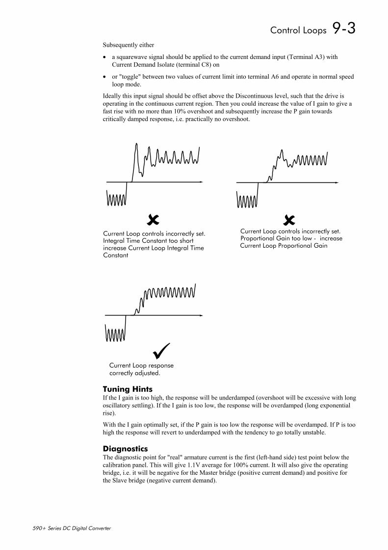
Control Loops 9-3
590+ Series DC Digital Converter
Subsequently either
• a squarewave signal should be applied to the current demand input (Terminal A3) withCurrent Demand Isolate (terminal C8) on
• or "toggle" between two values of current limit into terminal A6 and operate in normal speedloop mode.
Ideally this input signal should be offset above the Discontinuous level, such that the drive isoperating in the continuous current region. Then you could increase the value of I gain to give afast rise with no more than 10% overshoot and subsequently increase the P gain towardscritically damped response, i.e. practically no overshoot.
Tuning HintsIf the I gain is too high, the response will be underdamped (overshoot will be excessive with longoscillatory settling). If the I gain is too low, the response will be overdamped (long exponentialrise).
With the I gain optimally set, if the P gain is too low the response will be overdamped. If P is toohigh the response will revert to underdamped with the tendency to go totally unstable.
DiagnosticsThe diagnostic point for "real" armature current is the first (left-hand side) test point below thecalibration panel. This will give 1.1V average for 100% current. It will also give the operatingbridge, i.e. it will be negative for the Master bridge (positive current demand) and positive forthe Slave bridge (negative current demand).
Current Loop controls incorrectly set.Proportional Gain too low - increaseCurrent Loop Proportional Gain
Current Loop controls incorrectly set.Integral Time Constant too shortincrease Current Loop Integral TimeConstant
Current Loop responsecorrectly adjusted.
9-4 Control Loops
590+ Series DC Digital Converter
Speed LoopThe speed loop accepts a demand from either an outside loop (i.e. position loop) or directly fromthe plant and forms the error signal which is the difference between demand and feedback. Theerror signal is fed into a Proportional + Integral compensator which produces the output of thespeed loop, i.e. the current demand signal.
The integral gain is translated into a Time Constant (secs) in the MMI which defines moreclearly the function of the compensator against a certain load time constant.
Speed Loop Synchronised with Current LoopThe proportional part of the P+I algorithm is executed immediately before each run of thecurrent loop, thus ensuring minimum time lag and therefore maximum bandwidth.
Combined Analog Tacho / Encoder FeedbackBy using the analog tacho f/b on the Proportional part of the P + I algorithm and the encoder f/bon the Integral part (using similar principle as in the current loop), the Converter combinesmaximum transient response with the increased steady-state accuracy of the digital feedback.Please refer to Eurotherm Drives Engineering Department for assistance in the use of thisfeature.
Current Demand Rate Limit (di/dt)Access to the di/dt limit is currently reserved for Eurotherm Drives personnel only in theReserved Menu.
This is a limit imposed on the rate of change of the current demand. It is to be used for motorswith commutation limitations, mechanical systems that cannot absorb rapid torque transients andalso as a means of limiting current overshoot for large current swings (e.g. 0 200%). Thedefault value is set at 35% (i.e. maximum allowable change is 35% of FLC in 1/6 mains cycle)which has no practical effect on the current response between 0 and 100%.
Field ControlSet-up NotesThe setting of the P + I gains for the current controller is done manually in much the same wayas described in Chapter 4: “Current Loop - Manual Tuning”, and one convenient way is toswitch several times from "quench" to "standby" mode and observe the current response 0 50% for rise time and overshoot.
The setting of the field weakening gains is achieved by observing the armature voltage feedbackfor overshoot and settling time. The EMF GAIN parameter defaults to 0.30 (real gain of 30) andnormally lies in the region 0.20 to 0.70 (larger settings normally lead to instability). The EMFLEAD parameter should be set at around the time constant for the field current loop. It defaultsto 2.00 (200ms). Finally, the EMF LAG parameter defaults to 40.00 (4000ms) and it shouldgenerally lie in the region of 10 to 50 times the "emf lead".
The tuning of the field weakening loop is also very dependent on the acceleration rate throughbase speed and visa-versa. If armature voltage overshoot is a problem for rapid accelerationrates, then the use of the "feedback lead/lag" compensator is recommended to limit the overshootas discussed above. If not, then the default values for the above bemf fbk gains arerecommended (i.e. disabled) which will probably allow further increase in the forward pathtransfer function gains ("emf gain" and "emf lead") for faster field response.
In summary, the increased attenuation at the higher frequencies will allow an increase in the gainwhilst maintaining the desired phase margin. Bearing in mind that the negative angle of thecompensator lowers the angle curve, in order to maintain the desired phase margin (45 to 60degrees) a reduction in the phase-margin frequency is required. This is the frequency at whichthe log magnitude curve crosses the 0db line. Since the phase-margin frequency is indicative ofthe speed of response of the system, its reduction should be kept to a minimum. This isachievable by trying to keep the value of the corner-frequency 1 / T1 as low as possible bysetting T1 at values greater than 100ms or so. The upper limit for T1 will be dictated by thesettling time requirement.
Control Loops 9-5
590+ Series DC Digital Converter
Current ControlThe field current loop can accept a demand directly from the plant and/or an outside fieldweakening loop and forms the error signal which is the difference between demand andfeedback. The error signal is fed into a P + I compensator which produces the output of the fieldloop, i.e. the field firing angle signal.
The firing angle signal is translated into a certain time delay from the mains zero cross point(obtained via the same Phase-Lock-Loop as for the armature) and this results into a firingcommand being issued to the field bridge every 1/2 of a mains cycle in steady-state.
Voltage ControlThis offers the facility of an open-loop voltage control for motors which do not provide in thenameplate the field current rating. The field voltage is controlled by the specified RATIOOUT/IN which defaults to 90%. This is the maximum dc Volts that can be obtained for a givenac RMS input in a single-phase rectifier, i.e. 370V dc for 415V ac supply. The specified ratiodetermines directly the firing angle at which the controller operates and therefore the thermaleffects on the field resistance as well as mains voltage variations are not compensated for. It isalso worth noting that in this mode the field overcurrent alarm is not active (since there is nocurrent scaling) and therefore this mode is not recommended for use with supplies much greaterthan the field voltage rating.
Field WeakeningThe field weakening loop accepts a demand for MAX VOLTS (default 100%) and forms theerror signal which is the difference between demand and arm. volts feedback. The error signal isfed into a Lead/Lag compensator which produces the output of the field weakening loop, i.e. thefield weakening demand. This gets subtracted from the field setpoint (default 100%) to producethe field demand into the field current loop. A MIN FLD CURRENT parameter (default 10%)limits the minimum level in the field weakening region.
The Lead/Lag compensator has a dc gain ("emf gain" = Kp), a lead time constant ("emf lead" =T1) and a lag time constant ("emf lag" = T2).
Note: Field weakening is not possible when running with Armature Volts feedback. Althoughfield weakening can be “enabled” in this instance, a software interlock clamps the fielddemand at 100% and will not allow the field weakening to reduce it.
Lead/LagThe slight disadvantage of Lead/Lag transfer function = Kp * ( 1+sT1 ) / ( 1+sT2 ) versus P + I transfer function = Kp * ( 1+sT ) / sT is that the DC gain is not "infinity"and therefore there is a "finite" steady-state error. This is kept sufficiently small for values of"emf gain" > 0.20 ( i.e. real 20).
The advantage of the Lead/Lag is that it allows greater attenuation at higher frequencies. Thehigh frequency gain is Kp T1 / T2 and therefore by keeping the ratio T2 / T1 high (generally atvalues above 10) the log magnitude is reduced by 20log(T2/T1) for frequencies above 1 / T1.
An extra feedback lead/lag compensator has been added into the arm. volts f/b to minimise theovershoot in volts. This is particularly useful when accelerating fast through base speed andtherefore increasing the motor bemf at a faster rate than the field current can possibly weaken,due to the normally large field time constant. The ratio of "bemf fbk lead" / "bemf fbk lag"should always be greater than 1 to give a "lead" function to allow the field to start weakeningearly enough. However, it is not recommended to raise the ratio much higher than 2 to 3 times,otherwise instability will start creeping in. The absolute setting of the above parameters inmilliseconds depends on the overall field time constant. The default value is set to 1 (100ms /100ms) which means that the function is disabled.
Standby FieldWhen the armature current gets quenched, a timer starts timing-out and after a certain delay ("fldquench delay") it will either quench the field totally ("fld quench mode" = "quench") or willreduce it to 50% of the current or voltage setpoint ("fld quench mode" = "standby"). This appliesto both current and voltage modes.

9-6 Control Loops
590+ Series DC Digital Converter
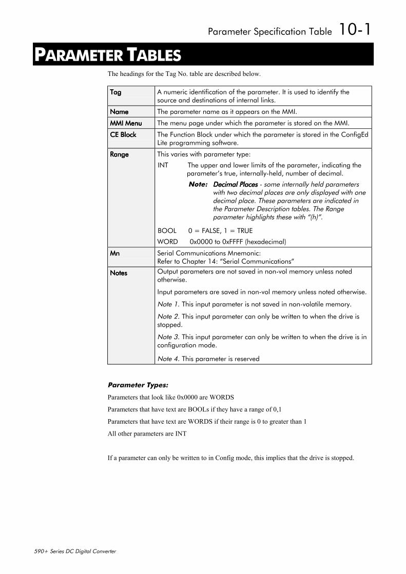
Parameter Specification Table 10-1
590+ Series DC Digital Converter
10 PARAMETER TABLESThe headings for the Tag No. table are described below.
TagTagTagTag A numeric identification of the parameter. It is used to identify thesource and destinations of internal links.
NameNameNameName The parameter name as it appears on the MMI.
MMI MenuMMI MenuMMI MenuMMI Menu The menu page under which the parameter is stored on the MMI.
CE BlockCE BlockCE BlockCE Block The Function Block under which the parameter is stored in the ConfigEdLite programming software.
RangeRangeRangeRange This varies with parameter type:
INT The upper and lower limits of the parameter, indicating theparameter’s true, internally-held, number of decimal.
Note: Decimal PlacesDecimal PlacesDecimal PlacesDecimal Places - some internally held parameterswith two decimal places are only displayed with onedecimal place. These parameters are indicated inthe Parameter Description tables. The Rangeparameter highlights these with “(h)”.
BOOL 0 = FALSE, 1 = TRUE
WORD 0x0000 to 0xFFFF (hexadecimal)
MnMnMnMn Serial Communications Mnemonic:Refer to Chapter 14: “Serial Communications”
NotesNotesNotesNotes Output parameters are not saved in non-vol memory unless notedotherwise.
Input parameters are saved in non-vol memory unless noted otherwise.
Note 1. This input parameter is not saved in non-volatile memory.
Note 2. This input parameter can only be written to when the drive isstopped.
Note 3. This input parameter can only be written to when the drive is inconfiguration mode.
Note 4. This parameter is reserved
Parameter Types:
Parameters that look like 0x0000 are WORDS
Parameters that have text are BOOLs if they have a range of 0,1
Parameters that have text are WORDS if their range is 0 to greater than 1
All other parameters are INT
If a parameter can only be written to in Config mode, this implies that the drive is stopped.
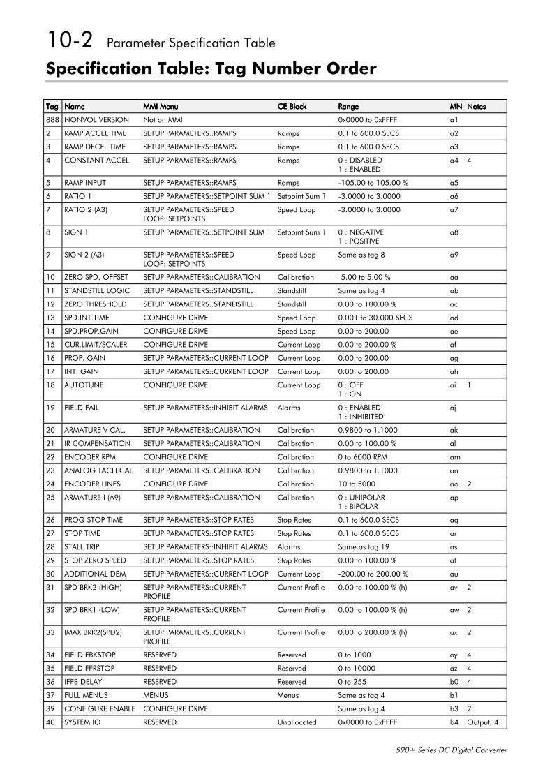
10-2 Parameter Specification Table
590+ Series DC Digital Converter
Specification Table: Tag Number Order
TagTagTagTag NameNameNameName MMI MenuMMI MenuMMI MenuMMI Menu CE BlockCE BlockCE BlockCE Block RangeRangeRangeRange MNMNMNMN NotesNotesNotesNotes
888 NONVOL VERSION Not on MMI 0x0000 to 0xFFFF a1
2 RAMP ACCEL TIME SETUP PARAMETERS::RAMPS Ramps 0.1 to 600.0 SECS a2
3 RAMP DECEL TIME SETUP PARAMETERS::RAMPS Ramps 0.1 to 600.0 SECS a3
4 CONSTANT ACCEL SETUP PARAMETERS::RAMPS Ramps 0 : DISABLED1 : ENABLED
a4 4
5 RAMP INPUT SETUP PARAMETERS::RAMPS Ramps -105.00 to 105.00 % a5
6 RATIO 1 SETUP PARAMETERS::SETPOINT SUM 1 Setpoint Sum 1 -3.0000 to 3.0000 a6
7 RATIO 2 (A3) SETUP PARAMETERS::SPEEDLOOP::SETPOINTS
Speed Loop -3.0000 to 3.0000 a7
8 SIGN 1 SETUP PARAMETERS::SETPOINT SUM 1 Setpoint Sum 1 0 : NEGATIVE1 : POSITIVE
a8
9 SIGN 2 (A3) SETUP PARAMETERS::SPEEDLOOP::SETPOINTS
Speed Loop Same as tag 8 a9
10 ZERO SPD. OFFSET SETUP PARAMETERS::CALIBRATION Calibration -5.00 to 5.00 % aa
11 STANDSTILL LOGIC SETUP PARAMETERS::STANDSTILL Standstill Same as tag 4 ab
12 ZERO THRESHOLD SETUP PARAMETERS::STANDSTILL Standstill 0.00 to 100.00 % ac
13 SPD.INT.TIME CONFIGURE DRIVE Speed Loop 0.001 to 30.000 SECS ad
14 SPD.PROP.GAIN CONFIGURE DRIVE Speed Loop 0.00 to 200.00 ae
15 CUR.LIMIT/SCALER CONFIGURE DRIVE Current Loop 0.00 to 200.00 % af
16 PROP. GAIN SETUP PARAMETERS::CURRENT LOOP Current Loop 0.00 to 200.00 ag
17 INT. GAIN SETUP PARAMETERS::CURRENT LOOP Current Loop 0.00 to 200.00 ah
18 AUTOTUNE CONFIGURE DRIVE Current Loop 0 : OFF1 : ON
ai 1
19 FIELD FAIL SETUP PARAMETERS::INHIBIT ALARMS Alarms 0 : ENABLED1 : INHIBITED
aj
20 ARMATURE V CAL. SETUP PARAMETERS::CALIBRATION Calibration 0.9800 to 1.1000 ak
21 IR COMPENSATION SETUP PARAMETERS::CALIBRATION Calibration 0.00 to 100.00 % al
22 ENCODER RPM CONFIGURE DRIVE Calibration 0 to 6000 RPM am
23 ANALOG TACH CAL SETUP PARAMETERS::CALIBRATION Calibration 0.9800 to 1.1000 an
24 ENCODER LINES CONFIGURE DRIVE Calibration 10 to 5000 ao 2
25 ARMATURE I (A9) SETUP PARAMETERS::CALIBRATION Calibration 0 : UNIPOLAR1 : BIPOLAR
ap
26 PROG STOP TIME SETUP PARAMETERS::STOP RATES Stop Rates 0.1 to 600.0 SECS aq
27 STOP TIME SETUP PARAMETERS::STOP RATES Stop Rates 0.1 to 600.0 SECS ar
28 STALL TRIP SETUP PARAMETERS::INHIBIT ALARMS Alarms Same as tag 19 as
29 STOP ZERO SPEED SETUP PARAMETERS::STOP RATES Stop Rates 0.00 to 100.00 % at
30 ADDITIONAL DEM SETUP PARAMETERS::CURRENT LOOP Current Loop -200.00 to 200.00 % au
31 SPD BRK2 (HIGH) SETUP PARAMETERS::CURRENTPROFILE
Current Profile 0.00 to 100.00 % (h) av 2
32 SPD BRK1 (LOW) SETUP PARAMETERS::CURRENTPROFILE
Current Profile 0.00 to 100.00 % (h) aw 2
33 IMAX BRK2(SPD2) SETUP PARAMETERS::CURRENTPROFILE
Current Profile 0.00 to 200.00 % (h) ax 2
34 FIELD FBKSTOP RESERVED Reserved 0 to 1000 ay 4
35 FIELD FFRSTOP RESERVED Reserved 0 to 10000 az 4
36 IFFB DELAY RESERVED Reserved 0 to 255 b0 4
37 FULL MENUS MENUS Menus Same as tag 4 b1
39 CONFIGURE ENABLE CONFIGURE DRIVE Same as tag 4 b3 2
40 SYSTEM IO RESERVED Unallocated 0x0000 to 0xFFFF b4 Output, 4
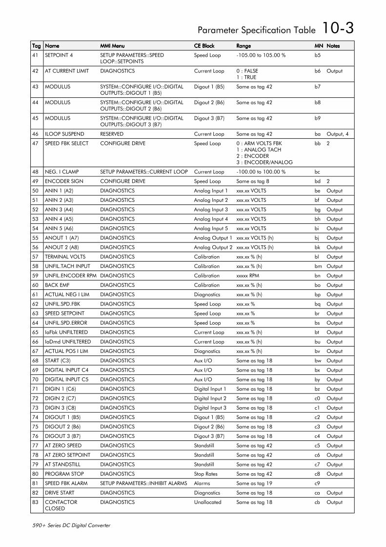
Parameter Specification Table 10-3
590+ Series DC Digital Converter
TagTagTagTag NameNameNameName MMI MenuMMI MenuMMI MenuMMI Menu CE BlockCE BlockCE BlockCE Block RangeRangeRangeRange MNMNMNMN NotesNotesNotesNotes
41 SETPOINT 4 SETUP PARAMETERS::SPEEDLOOP::SETPOINTS
Speed Loop -105.00 to 105.00 % b5
42 AT CURRENT LIMIT DIAGNOSTICS Current Loop 0 : FALSE1 : TRUE
b6 Output
43 MODULUS SYSTEM::CONFIGURE I/O::DIGITALOUTPUTS::DIGOUT 1 (B5)
Digout 1 (B5) Same as tag 42 b7
44 MODULUS SYSTEM::CONFIGURE I/O::DIGITALOUTPUTS::DIGOUT 2 (B6)
Digout 2 (B6) Same as tag 42 b8
45 MODULUS SYSTEM::CONFIGURE I/O::DIGITALOUTPUTS::DIGOUT 3 (B7)
Digout 3 (B7) Same as tag 42 b9
46 ILOOP SUSPEND RESERVED Current Loop Same as tag 42 ba Output, 4
47 SPEED FBK SELECT CONFIGURE DRIVE Speed Loop 0 : ARM VOLTS FBK1 : ANALOG TACH2 : ENCODER3 : ENCODER/ANALOG
bb 2
48 NEG. I CLAMP SETUP PARAMETERS::CURRENT LOOP Current Loop -100.00 to 100.00 % bc
49 ENCODER SIGN CONFIGURE DRIVE Speed Loop Same as tag 8 bd 2
50 ANIN 1 (A2) DIAGNOSTICS Analog Input 1 xxx.xx VOLTS be Output
51 ANIN 2 (A3) DIAGNOSTICS Analog Input 2 xxx.xx VOLTS bf Output
52 ANIN 3 (A4) DIAGNOSTICS Analog Input 3 xxx.xx VOLTS bg Output
53 ANIN 4 (A5) DIAGNOSTICS Analog Input 4 xxx.xx VOLTS bh Output
54 ANIN 5 (A6) DIAGNOSTICS Analog Input 5 xxx.xx VOLTS bi Output
55 ANOUT 1 (A7) DIAGNOSTICS Analog Output 1 xxx.xx VOLTS (h) bj Output
56 ANOUT 2 (A8) DIAGNOSTICS Analog Output 2 xxx.xx VOLTS (h) bk Output
57 TERMINAL VOLTS DIAGNOSTICS Calibration xxx.xx % (h) bl Output
58 UNFIL.TACH INPUT DIAGNOSTICS Calibration xxx.xx % (h) bm Output
59 UNFIL.ENCODER RPM DIAGNOSTICS Calibration xxxxx RPM bn Output
60 BACK EMF DIAGNOSTICS Calibration xxx.xx % (h) bo Output
61 ACTUAL NEG I LIM DIAGNOSTICS Diagnostics xxx.xx % (h) bp Output
62 UNFIL.SPD.FBK DIAGNOSTICS Speed Loop xxx.xx % bq Output
63 SPEED SETPOINT DIAGNOSTICS Speed Loop xxx.xx % br Output
64 UNFIL.SPD.ERROR DIAGNOSTICS Speed Loop xxx.xx % bs Output
65 IaFbk UNFILTERED DIAGNOSTICS Current Loop xxx.xx % (h) bt Output
66 IaDmd UNFILTERED DIAGNOSTICS Current Loop xxx.xx % (h) bu Output
67 ACTUAL POS I LIM DIAGNOSTICS Diagnostics xxx.xx % (h) bv Output
68 START (C3) DIAGNOSTICS Aux I/O Same as tag 18 bw Output
69 DIGITAL INPUT C4 DIAGNOSTICS Aux I/O Same as tag 18 bx Output
70 DIGITAL INPUT C5 DIAGNOSTICS Aux I/O Same as tag 18 by Output
71 DIGIN 1 (C6) DIAGNOSTICS Digital Input 1 Same as tag 18 bz Output
72 DIGIN 2 (C7) DIAGNOSTICS Digital Input 2 Same as tag 18 c0 Output
73 DIGIN 3 (C8) DIAGNOSTICS Digital Input 3 Same as tag 18 c1 Output
74 DIGOUT 1 (B5) DIAGNOSTICS Digout 1 (B5) Same as tag 18 c2 Output
75 DIGOUT 2 (B6) DIAGNOSTICS Digout 2 (B6) Same as tag 18 c3 Output
76 DIGOUT 3 (B7) DIAGNOSTICS Digout 3 (B7) Same as tag 18 c4 Output
77 AT ZERO SPEED DIAGNOSTICS Standstill Same as tag 42 c5 Output
78 AT ZERO SETPOINT DIAGNOSTICS Standstill Same as tag 42 c6 Output
79 AT STANDSTILL DIAGNOSTICS Standstill Same as tag 42 c7 Output
80 PROGRAM STOP DIAGNOSTICS Stop Rates Same as tag 42 c8 Output
81 SPEED FBK ALARM SETUP PARAMETERS::INHIBIT ALARMS Alarms Same as tag 19 c9
82 DRIVE START DIAGNOSTICS Diagnostics Same as tag 18 ca Output
83 CONTACTORCLOSED
DIAGNOSTICS Unallocated Same as tag 18 cb Output
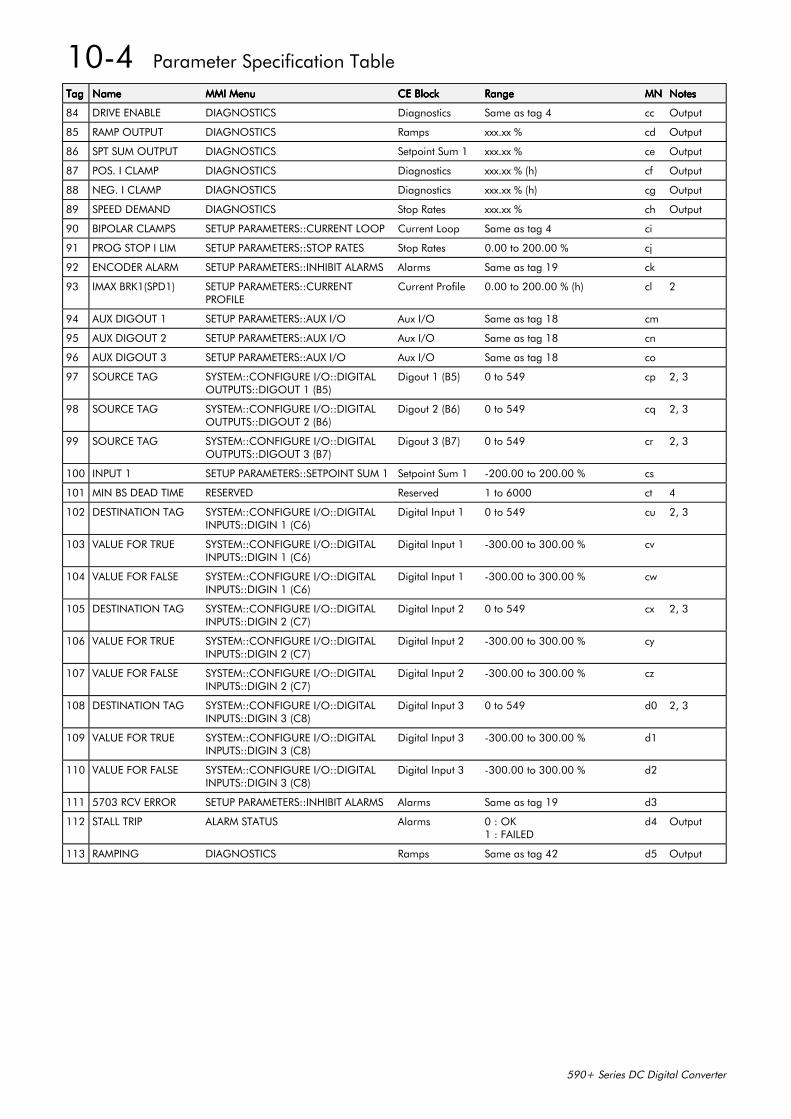
10-4 Parameter Specification Table
590+ Series DC Digital Converter
TagTagTagTag NameNameNameName MMI MenuMMI MenuMMI MenuMMI Menu CE BlockCE BlockCE BlockCE Block RangeRangeRangeRange MNMNMNMN NotesNotesNotesNotes
84 DRIVE ENABLE DIAGNOSTICS Diagnostics Same as tag 4 cc Output
85 RAMP OUTPUT DIAGNOSTICS Ramps xxx.xx % cd Output
86 SPT SUM OUTPUT DIAGNOSTICS Setpoint Sum 1 xxx.xx % ce Output
87 POS. I CLAMP DIAGNOSTICS Diagnostics xxx.xx % (h) cf Output
88 NEG. I CLAMP DIAGNOSTICS Diagnostics xxx.xx % (h) cg Output
89 SPEED DEMAND DIAGNOSTICS Stop Rates xxx.xx % ch Output
90 BIPOLAR CLAMPS SETUP PARAMETERS::CURRENT LOOP Current Loop Same as tag 4 ci
91 PROG STOP I LIM SETUP PARAMETERS::STOP RATES Stop Rates 0.00 to 200.00 % cj
92 ENCODER ALARM SETUP PARAMETERS::INHIBIT ALARMS Alarms Same as tag 19 ck
93 IMAX BRK1(SPD1) SETUP PARAMETERS::CURRENTPROFILE
Current Profile 0.00 to 200.00 % (h) cl 2
94 AUX DIGOUT 1 SETUP PARAMETERS::AUX I/O Aux I/O Same as tag 18 cm
95 AUX DIGOUT 2 SETUP PARAMETERS::AUX I/O Aux I/O Same as tag 18 cn
96 AUX DIGOUT 3 SETUP PARAMETERS::AUX I/O Aux I/O Same as tag 18 co
97 SOURCE TAG SYSTEM::CONFIGURE I/O::DIGITALOUTPUTS::DIGOUT 1 (B5)
Digout 1 (B5) 0 to 549 cp 2, 3
98 SOURCE TAG SYSTEM::CONFIGURE I/O::DIGITALOUTPUTS::DIGOUT 2 (B6)
Digout 2 (B6) 0 to 549 cq 2, 3
99 SOURCE TAG SYSTEM::CONFIGURE I/O::DIGITALOUTPUTS::DIGOUT 3 (B7)
Digout 3 (B7) 0 to 549 cr 2, 3
100 INPUT 1 SETUP PARAMETERS::SETPOINT SUM 1 Setpoint Sum 1 -200.00 to 200.00 % cs
101 MIN BS DEAD TIME RESERVED Reserved 1 to 6000 ct 4
102 DESTINATION TAG SYSTEM::CONFIGURE I/O::DIGITALINPUTS::DIGIN 1 (C6)
Digital Input 1 0 to 549 cu 2, 3
103 VALUE FOR TRUE SYSTEM::CONFIGURE I/O::DIGITALINPUTS::DIGIN 1 (C6)
Digital Input 1 -300.00 to 300.00 % cv
104 VALUE FOR FALSE SYSTEM::CONFIGURE I/O::DIGITALINPUTS::DIGIN 1 (C6)
Digital Input 1 -300.00 to 300.00 % cw
105 DESTINATION TAG SYSTEM::CONFIGURE I/O::DIGITALINPUTS::DIGIN 2 (C7)
Digital Input 2 0 to 549 cx 2, 3
106 VALUE FOR TRUE SYSTEM::CONFIGURE I/O::DIGITALINPUTS::DIGIN 2 (C7)
Digital Input 2 -300.00 to 300.00 % cy
107 VALUE FOR FALSE SYSTEM::CONFIGURE I/O::DIGITALINPUTS::DIGIN 2 (C7)
Digital Input 2 -300.00 to 300.00 % cz
108 DESTINATION TAG SYSTEM::CONFIGURE I/O::DIGITALINPUTS::DIGIN 3 (C8)
Digital Input 3 0 to 549 d0 2, 3
109 VALUE FOR TRUE SYSTEM::CONFIGURE I/O::DIGITALINPUTS::DIGIN 3 (C8)
Digital Input 3 -300.00 to 300.00 % d1
110 VALUE FOR FALSE SYSTEM::CONFIGURE I/O::DIGITALINPUTS::DIGIN 3 (C8)
Digital Input 3 -300.00 to 300.00 % d2
111 5703 RCV ERROR SETUP PARAMETERS::INHIBIT ALARMS Alarms Same as tag 19 d3
112 STALL TRIP ALARM STATUS Alarms 0 : OK1 : FAILED
d4 Output
113 RAMPING DIAGNOSTICS Ramps Same as tag 42 d5 Output
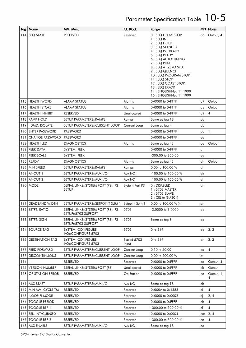
Parameter Specification Table 10-5
590+ Series DC Digital Converter
TagTagTagTag NameNameNameName MMI MenuMMI MenuMMI MenuMMI Menu CE BlockCE BlockCE BlockCE Block RangeRangeRangeRange MNMNMNMN NotesNotesNotesNotes
114 SEQ STATE RESERVED Reserved 0 : SEQ DELAY STOP1 : SEQ INIT2 : SEQ HOLD3 : SEQ STANDBY4 : SEQ PRE READY5 : SEQ READY6 : SEQ AUTOTUNING7 : SEQ RUN8 : SEQ AT ZERO SPD.9 : SEQ QUENCH10 : SEQ PROGRAM STOP11 : SEQ STOP12 : SEQ COAST STOP13 : SEQ ERROR14 : ENGLISHNov 11 199915 : ENGLISHNov 11 1999
d6 Output, 4
115 HEALTH WORD ALARM STATUS Alarms 0x0000 to 0xFFFF d7 Output
116 HEALTH STORE ALARM STATUS Alarms 0x0000 to 0xFFFF d8 Output
117 HEALTH INHIBIT RESERVED Unallocated 0x0000 to 0xFFFF d9 4
118 RAMP HOLD SETUP PARAMETERS::RAMPS Ramps Same as tag 18 da
119 I DMD. ISOLATE SETUP PARAMETERS::CURRENT LOOP Current Loop Same as tag 4 db
120 ENTER PASSWORD PASSWORD 0x0000 to 0xFFFF dc 1
121 CHANGE PASSWORD PASSWORD 0x0000 to 0xFFFF dd
122 HEALTH LED DIAGNOSTICS Alarms Same as tag 42 de Output
123 PEEK DATA SYSTEM::PEEK 0x0000 to 0xFFFF df
124 PEEK SCALE SYSTEM::PEEK -300.00 to 300.00 dg
125 READY DIAGNOSTICS Alarms Same as tag 42 dh Output
126 MIN SPEED SETUP PARAMETERS::RAMPS Ramps 0.00 to 100.00 % di
128 ANOUT 1 SETUP PARAMETERS::AUX I/O Aux I/O -100.00 to 100.00 % dk
129 ANOUT 2 SETUP PARAMETERS::AUX I/O Aux I/O -100.00 to 100.00 % dl
130 MODE SERIAL LINKS::SYSTEM PORT (P3)::P3SETUP
System Port P3 0 : DISABLED1 : 5703 MASTER2 : 5703 SLAVE3 : CELite (EIASCII)
dm
131 DEADBAND WIDTH SETUP PARAMETERS::SETPOINT SUM 1 Setpoint Sum 1 0.00 to 100.00 % (h) dn
132 SETPT. RATIO SERIAL LINKS::SYSTEM PORT (P3)::P3SETUP::5703 SUPPORT
5703 -3.0000 to 3.0000 do
133 SETPT. SIGN SERIAL LINKS::SYSTEM PORT (P3)::P3SETUP::5703 SUPPORT
5703 Same as tag 8 dp
134 SOURCE TAG SYSTEM::CONFIGUREI/O::CONFIGURE 5703
5703 0 to 549 dq 2, 3
135 DESTINATION TAG SYSTEM::CONFIGUREI/O::CONFIGURE 5703
Scaled 5703Input
0 to 549 dr 2, 3
136 FEED FORWARD SETUP PARAMETERS::CURRENT LOOP Current Loop 0.10 to 50.00 ds 4
137 DISCONTINUOUS SETUP PARAMETERS::CURRENT LOOP Current Loop 0.00 to 200.00 % dt
154 II RESERVED Reserved 0x0000 to 0xFFFF ea Output, 4
155 VERSION NUMBER SERIAL LINKS::SYSTEM PORT (P3) Unallocated 0x0000 to 0xFFFF eb Output
158 OP STATION ERROR RESERVED Op Station 0x0000 to 0xFFFF ee Output, 1,4
161 AUX START SETUP PARAMETERS::AUX I/O Aux I/O Same as tag 18 eh
162 MIN MMI CYCLE TM RESERVED Reserved 0x000A to 0x1388 ei 4
163 ILOOP PI MODE RESERVED Reserved 0x0000 to 0x0002 ej 2, 4
164 TOGGLE PERIOD RESERVED Reserved 0x0000 to 0xFFFF ek 4
165 TOGGLE REF 1 RESERVED Reserved -300.00 to 300.00 % el 4
166 SEL. INT/CUR/SPD RESERVED Reserved 0x0000 to 0x0004 em 2, 4
167 TOGGLE REF 2 RESERVED Reserved -300.00 to 300.00 % en 4
168 AUX ENABLE SETUP PARAMETERS::AUX I/O Aux I/O Same as tag 18 eo
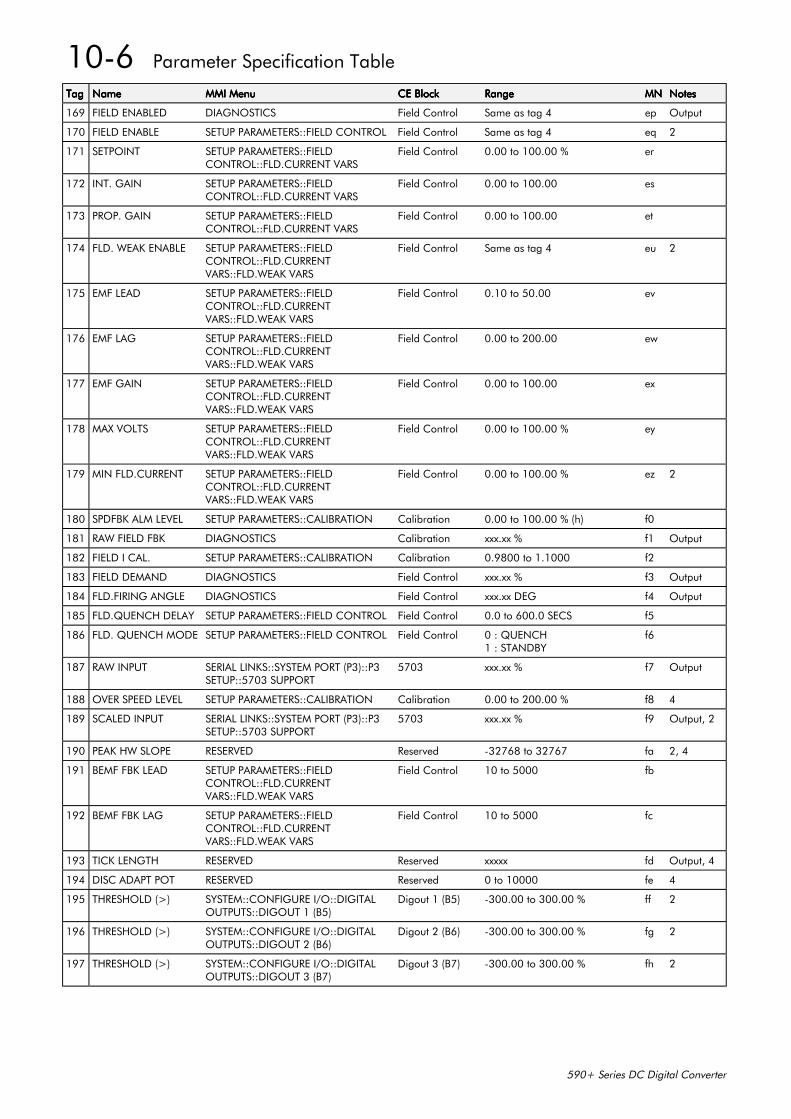
10-6 Parameter Specification Table
590+ Series DC Digital Converter
TagTagTagTag NameNameNameName MMI MenuMMI MenuMMI MenuMMI Menu CE BlockCE BlockCE BlockCE Block RangeRangeRangeRange MNMNMNMN NotesNotesNotesNotes
169 FIELD ENABLED DIAGNOSTICS Field Control Same as tag 4 ep Output
170 FIELD ENABLE SETUP PARAMETERS::FIELD CONTROL Field Control Same as tag 4 eq 2
171 SETPOINT SETUP PARAMETERS::FIELDCONTROL::FLD.CURRENT VARS
Field Control 0.00 to 100.00 % er
172 INT. GAIN SETUP PARAMETERS::FIELDCONTROL::FLD.CURRENT VARS
Field Control 0.00 to 100.00 es
173 PROP. GAIN SETUP PARAMETERS::FIELDCONTROL::FLD.CURRENT VARS
Field Control 0.00 to 100.00 et
174 FLD. WEAK ENABLE SETUP PARAMETERS::FIELDCONTROL::FLD.CURRENTVARS::FLD.WEAK VARS
Field Control Same as tag 4 eu 2
175 EMF LEAD SETUP PARAMETERS::FIELDCONTROL::FLD.CURRENTVARS::FLD.WEAK VARS
Field Control 0.10 to 50.00 ev
176 EMF LAG SETUP PARAMETERS::FIELDCONTROL::FLD.CURRENTVARS::FLD.WEAK VARS
Field Control 0.00 to 200.00 ew
177 EMF GAIN SETUP PARAMETERS::FIELDCONTROL::FLD.CURRENTVARS::FLD.WEAK VARS
Field Control 0.00 to 100.00 ex
178 MAX VOLTS SETUP PARAMETERS::FIELDCONTROL::FLD.CURRENTVARS::FLD.WEAK VARS
Field Control 0.00 to 100.00 % ey
179 MIN FLD.CURRENT SETUP PARAMETERS::FIELDCONTROL::FLD.CURRENTVARS::FLD.WEAK VARS
Field Control 0.00 to 100.00 % ez 2
180 SPDFBK ALM LEVEL SETUP PARAMETERS::CALIBRATION Calibration 0.00 to 100.00 % (h) f0
181 RAW FIELD FBK DIAGNOSTICS Calibration xxx.xx % f1 Output
182 FIELD I CAL. SETUP PARAMETERS::CALIBRATION Calibration 0.9800 to 1.1000 f2
183 FIELD DEMAND DIAGNOSTICS Field Control xxx.xx % f3 Output
184 FLD.FIRING ANGLE DIAGNOSTICS Field Control xxx.xx DEG f4 Output
185 FLD.QUENCH DELAY SETUP PARAMETERS::FIELD CONTROL Field Control 0.0 to 600.0 SECS f5
186 FLD. QUENCH MODE SETUP PARAMETERS::FIELD CONTROL Field Control 0 : QUENCH1 : STANDBY
f6
187 RAW INPUT SERIAL LINKS::SYSTEM PORT (P3)::P3SETUP::5703 SUPPORT
5703 xxx.xx % f7 Output
188 OVER SPEED LEVEL SETUP PARAMETERS::CALIBRATION Calibration 0.00 to 200.00 % f8 4
189 SCALED INPUT SERIAL LINKS::SYSTEM PORT (P3)::P3SETUP::5703 SUPPORT
5703 xxx.xx % f9 Output, 2
190 PEAK HW SLOPE RESERVED Reserved -32768 to 32767 fa 2, 4
191 BEMF FBK LEAD SETUP PARAMETERS::FIELDCONTROL::FLD.CURRENTVARS::FLD.WEAK VARS
Field Control 10 to 5000 fb
192 BEMF FBK LAG SETUP PARAMETERS::FIELDCONTROL::FLD.CURRENTVARS::FLD.WEAK VARS
Field Control 10 to 5000 fc
193 TICK LENGTH RESERVED Reserved xxxxx fd Output, 4
194 DISC ADAPT POT RESERVED Reserved 0 to 10000 fe 4
195 THRESHOLD (>) SYSTEM::CONFIGURE I/O::DIGITALOUTPUTS::DIGOUT 1 (B5)
Digout 1 (B5) -300.00 to 300.00 % ff 2
196 THRESHOLD (>) SYSTEM::CONFIGURE I/O::DIGITALOUTPUTS::DIGOUT 2 (B6)
Digout 2 (B6) -300.00 to 300.00 % fg 2
197 THRESHOLD (>) SYSTEM::CONFIGURE I/O::DIGITALOUTPUTS::DIGOUT 3 (B7)
Digout 3 (B7) -300.00 to 300.00 % fh 2
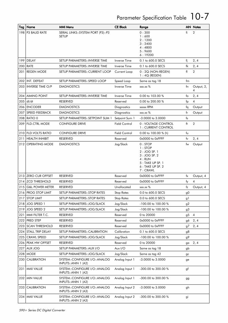
Parameter Specification Table 10-7
590+ Series DC Digital Converter
TagTagTagTag NameNameNameName MMI MenuMMI MenuMMI MenuMMI Menu CE BlockCE BlockCE BlockCE Block RangeRangeRangeRange MNMNMNMN NotesNotesNotesNotes
198 P3 BAUD RATE SERIAL LINKS::SYSTEM PORT (P3)::P3SETUP
0 : 3001 : 6002 : 12003 : 24004 : 48005 : 96006 : 19200
fi 2
199 DELAY SETUP PARAMETERS::INVERSE TIME Inverse Time 0.1 to 600.0 SECS fj 2, 4
200 RATE SETUP PARAMETERS::INVERSE TIME Inverse Time 0.1 to 600.0 SECS fk 2, 4
201 REGEN MODE SETUP PARAMETERS::CURRENT LOOP Current Loop 0 : 2Q (NON-REGEN)1 : 4Q (REGEN)
fl 2
202 INT. DEFEAT SETUP PARAMETERS::SPEED LOOP Speed Loop Same as tag 18 fm
203 INVERSE TIME O/P DIAGNOSTICS Inverse Time xxx.xx % fn Output, 2,4
204 AIMING POINT SETUP PARAMETERS::INVERSE TIME Inverse Time 0.00 to 103.00 % fo 2, 4
205 dI/dt RESERVED Reserved 0.00 to 200.00 % fp 4
206 ENCODER DIAGNOSTICS Diagnostics xxxxx RPM fq Output
207 SPEED FEEDBACK DIAGNOSTICS Diagnostics xxx.xx % fr Output
208 RATIO 0 SETUP PARAMETERS::SETPOINT SUM 1 Setpoint Sum 1 -3.0000 to 3.0000 fs
209 FLD.CTRL MODE CONFIGURE DRIVE Field Control 0 : VOLTAGE CONTROL1 : CURRENT CONTROL
ft 2
210 FLD.VOLTS RATIO CONFIGURE DRIVE Field Control 0.00 to 100.00 % (h) fu
211 HEALTH INHIBIT RESERVED Reserved 0x0000 to 0xFFFF fv 2, 4
212 OPERATING MODE DIAGNOSTICS Jog/Slack 0 : STOP1 : STOP2 : JOG SP. 13 : JOG SP. 24 : RUN5 : TAKE UP SP. 16 : TAKE UP SP. 27 : CRAWL
fw Output
213 ZERO CUR OFFSET RESERVED Reserved 0x0000 to 0xFFFF fx Output, 4
214 ZCD THRESHOLD RESERVED Reserved 0x0000 to 0xFFFF fy 4
215 G&L POWER METER RESERVED Unallocated xxx.xx % fz Output, 4
216 PROG STOP LIMIT SETUP PARAMETERS::STOP RATES Stop Rates 0.0 to 600.0 SECS g0
217 STOP LIMIT SETUP PARAMETERS::STOP RATES Stop Rates 0.0 to 600.0 SECS g1
218 JOG SPEED 1 SETUP PARAMETERS::JOG/SLACK Jog/Slack -100.00 to 100.00 % g2
219 JOG SPEED 2 SETUP PARAMETERS::JOG/SLACK Jog/Slack -100.00 to 100.00 % g3
221 MMI FILTER T.C. RESERVED Reserved 0 to 20000 g5 4
222 PRED STEP RESERVED Reserved 0x0000 to 0xFFFF g6 2, 4
223 SCAN THRESHOLD RESERVED Reserved 0x0000 to 0xFFFF g7 2, 4
224 STALL TRIP DELAY SETUP PARAMETERS::CALIBRATION Calibration 0.1 to 600.0 SECS g8
225 CRAWL SPEED SETUP PARAMETERS::JOG/SLACK Jog/Slack -100.00 to 100.00 % g9
226 PEAK HW OFFSET RESERVED Reserved 0 to 20000 ga 2, 4
227 AUX JOG SETUP PARAMETERS::AUX I/O Aux I/O Same as tag 18 gb
228 MODE SETUP PARAMETERS::JOG/SLACK Jog/Slack Same as tag 42 gc
230 CALIBRATION SYSTEM::CONFIGURE I/O::ANALOGINPUTS::ANIN 1 (A2)
Analog Input 1 -3.0000 to 3.0000 ge
231 MAX VALUE SYSTEM::CONFIGURE I/O::ANALOGINPUTS::ANIN 1 (A2)
Analog Input 1 -300.00 to 300.00 % gf
232 MIN VALUE SYSTEM::CONFIGURE I/O::ANALOGINPUTS::ANIN 1 (A2)
Analog Input 1 -300.00 to 300.00 % gg
233 CALIBRATION SYSTEM::CONFIGURE I/O::ANALOGINPUTS::ANIN 2 (A3)
Analog Input 2 -3.0000 to 3.0000 gh
234 MAX VALUE SYSTEM::CONFIGURE I/O::ANALOGINPUTS::ANIN 2 (A3)
Analog Input 2 -300.00 to 300.00 % gi
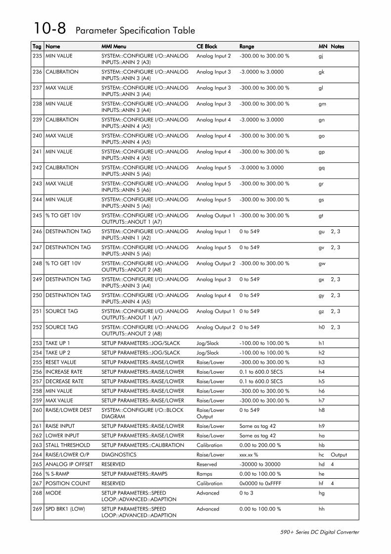
10-8 Parameter Specification Table
590+ Series DC Digital Converter
TagTagTagTag NameNameNameName MMI MenuMMI MenuMMI MenuMMI Menu CE BlockCE BlockCE BlockCE Block RangeRangeRangeRange MNMNMNMN NotesNotesNotesNotes
235 MIN VALUE SYSTEM::CONFIGURE I/O::ANALOGINPUTS::ANIN 2 (A3)
Analog Input 2 -300.00 to 300.00 % gj
236 CALIBRATION SYSTEM::CONFIGURE I/O::ANALOGINPUTS::ANIN 3 (A4)
Analog Input 3 -3.0000 to 3.0000 gk
237 MAX VALUE SYSTEM::CONFIGURE I/O::ANALOGINPUTS::ANIN 3 (A4)
Analog Input 3 -300.00 to 300.00 % gl
238 MIN VALUE SYSTEM::CONFIGURE I/O::ANALOGINPUTS::ANIN 3 (A4)
Analog Input 3 -300.00 to 300.00 % gm
239 CALIBRATION SYSTEM::CONFIGURE I/O::ANALOGINPUTS::ANIN 4 (A5)
Analog Input 4 -3.0000 to 3.0000 gn
240 MAX VALUE SYSTEM::CONFIGURE I/O::ANALOGINPUTS::ANIN 4 (A5)
Analog Input 4 -300.00 to 300.00 % go
241 MIN VALUE SYSTEM::CONFIGURE I/O::ANALOGINPUTS::ANIN 4 (A5)
Analog Input 4 -300.00 to 300.00 % gp
242 CALIBRATION SYSTEM::CONFIGURE I/O::ANALOGINPUTS::ANIN 5 (A6)
Analog Input 5 -3.0000 to 3.0000 gq
243 MAX VALUE SYSTEM::CONFIGURE I/O::ANALOGINPUTS::ANIN 5 (A6)
Analog Input 5 -300.00 to 300.00 % gr
244 MIN VALUE SYSTEM::CONFIGURE I/O::ANALOGINPUTS::ANIN 5 (A6)
Analog Input 5 -300.00 to 300.00 % gs
245 % TO GET 10V SYSTEM::CONFIGURE I/O::ANALOGOUTPUTS::ANOUT 1 (A7)
Analog Output 1 -300.00 to 300.00 % gt
246 DESTINATION TAG SYSTEM::CONFIGURE I/O::ANALOGINPUTS::ANIN 1 (A2)
Analog Input 1 0 to 549 gu 2, 3
247 DESTINATION TAG SYSTEM::CONFIGURE I/O::ANALOGINPUTS::ANIN 5 (A6)
Analog Input 5 0 to 549 gv 2, 3
248 % TO GET 10V SYSTEM::CONFIGURE I/O::ANALOGOUTPUTS::ANOUT 2 (A8)
Analog Output 2 -300.00 to 300.00 % gw
249 DESTINATION TAG SYSTEM::CONFIGURE I/O::ANALOGINPUTS::ANIN 3 (A4)
Analog Input 3 0 to 549 gx 2, 3
250 DESTINATION TAG SYSTEM::CONFIGURE I/O::ANALOGINPUTS::ANIN 4 (A5)
Analog Input 4 0 to 549 gy 2, 3
251 SOURCE TAG SYSTEM::CONFIGURE I/O::ANALOGOUTPUTS::ANOUT 1 (A7)
Analog Output 1 0 to 549 gz 2, 3
252 SOURCE TAG SYSTEM::CONFIGURE I/O::ANALOGOUTPUTS::ANOUT 2 (A8)
Analog Output 2 0 to 549 h0 2, 3
253 TAKE UP 1 SETUP PARAMETERS::JOG/SLACK Jog/Slack -100.00 to 100.00 % h1
254 TAKE UP 2 SETUP PARAMETERS::JOG/SLACK Jog/Slack -100.00 to 100.00 % h2
255 RESET VALUE SETUP PARAMETERS::RAISE/LOWER Raise/Lower -300.00 to 300.00 % h3
256 INCREASE RATE SETUP PARAMETERS::RAISE/LOWER Raise/Lower 0.1 to 600.0 SECS h4
257 DECREASE RATE SETUP PARAMETERS::RAISE/LOWER Raise/Lower 0.1 to 600.0 SECS h5
258 MIN VALUE SETUP PARAMETERS::RAISE/LOWER Raise/Lower -300.00 to 300.00 % h6
259 MAX VALUE SETUP PARAMETERS::RAISE/LOWER Raise/Lower -300.00 to 300.00 % h7
260 RAISE/LOWER DEST SYSTEM::CONFIGURE I/O::BLOCKDIAGRAM
Raise/LowerOutput
0 to 549 h8
261 RAISE INPUT SETUP PARAMETERS::RAISE/LOWER Raise/Lower Same as tag 42 h9
262 LOWER INPUT SETUP PARAMETERS::RAISE/LOWER Raise/Lower Same as tag 42 ha
263 STALL THRESHOLD SETUP PARAMETERS::CALIBRATION Calibration 0.00 to 200.00 % hb
264 RAISE/LOWER O/P DIAGNOSTICS Raise/Lower xxx.xx % hc Output
265 ANALOG IP OFFSET RESERVED Reserved -30000 to 30000 hd 4
266 % S-RAMP SETUP PARAMETERS::RAMPS Ramps 0.00 to 100.00 % he
267 POSITION COUNT RESERVED Calibration 0x0000 to 0xFFFF hf 4
268 MODE SETUP PARAMETERS::SPEEDLOOP::ADVANCED::ADAPTION
Advanced 0 to 3 hg
269 SPD BRK1 (LOW) SETUP PARAMETERS::SPEEDLOOP::ADVANCED::ADAPTION
Advanced 0.00 to 100.00 % hh
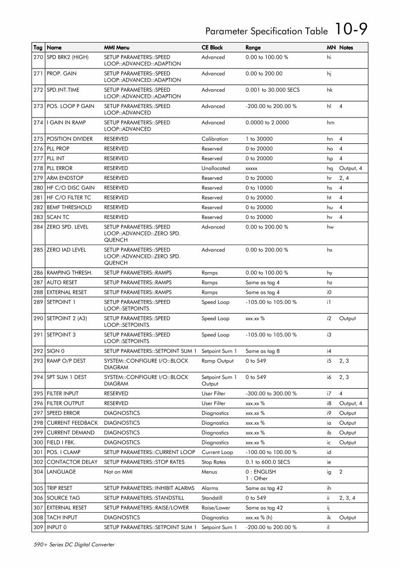
Parameter Specification Table 10-9
590+ Series DC Digital Converter
TagTagTagTag NameNameNameName MMI MenuMMI MenuMMI MenuMMI Menu CE BlockCE BlockCE BlockCE Block RangeRangeRangeRange MNMNMNMN NotesNotesNotesNotes
270 SPD BRK2 (HIGH) SETUP PARAMETERS::SPEEDLOOP::ADVANCED::ADAPTION
Advanced 0.00 to 100.00 % hi
271 PROP. GAIN SETUP PARAMETERS::SPEEDLOOP::ADVANCED::ADAPTION
Advanced 0.00 to 200.00 hj
272 SPD.INT.TIME SETUP PARAMETERS::SPEEDLOOP::ADVANCED::ADAPTION
Advanced 0.001 to 30.000 SECS hk
273 POS. LOOP P GAIN SETUP PARAMETERS::SPEEDLOOP::ADVANCED
Advanced -200.00 to 200.00 % hl 4
274 I GAIN IN RAMP SETUP PARAMETERS::SPEEDLOOP::ADVANCED
Advanced 0.0000 to 2.0000 hm
275 POSITION DIVIDER RESERVED Calibration 1 to 30000 hn 4
276 PLL PROP RESERVED Reserved 0 to 20000 ho 4
277 PLL INT RESERVED Reserved 0 to 20000 hp 4
278 PLL ERROR RESERVED Unallocated xxxxx hq Output, 4
279 ARM ENDSTOP RESERVED Reserved 0 to 20000 hr 2, 4
280 HF C/O DISC GAIN RESERVED Reserved 0 to 10000 hs 4
281 HF C/O FILTER TC RESERVED Reserved 0 to 20000 ht 4
282 BEMF THRESHOLD RESERVED Reserved 0 to 20000 hu 4
283 SCAN TC RESERVED Reserved 0 to 20000 hv 4
284 ZERO SPD. LEVEL SETUP PARAMETERS::SPEEDLOOP::ADVANCED::ZERO SPD.QUENCH
Advanced 0.00 to 200.00 % hw
285 ZERO IAD LEVEL SETUP PARAMETERS::SPEEDLOOP::ADVANCED::ZERO SPD.QUENCH
Advanced 0.00 to 200.00 % hx
286 RAMPING THRESH. SETUP PARAMETERS::RAMPS Ramps 0.00 to 100.00 % hy
287 AUTO RESET SETUP PARAMETERS::RAMPS Ramps Same as tag 4 hz
288 EXTERNAL RESET SETUP PARAMETERS::RAMPS Ramps Same as tag 4 i0
289 SETPOINT 1 SETUP PARAMETERS::SPEEDLOOP::SETPOINTS
Speed Loop -105.00 to 105.00 % i1
290 SETPOINT 2 (A3) SETUP PARAMETERS::SPEEDLOOP::SETPOINTS
Speed Loop xxx.xx % i2 Output
291 SETPOINT 3 SETUP PARAMETERS::SPEEDLOOP::SETPOINTS
Speed Loop -105.00 to 105.00 % i3
292 SIGN 0 SETUP PARAMETERS::SETPOINT SUM 1 Setpoint Sum 1 Same as tag 8 i4
293 RAMP O/P DEST SYSTEM::CONFIGURE I/O::BLOCKDIAGRAM
Ramp Output 0 to 549 i5 2, 3
294 SPT SUM 1 DEST SYSTEM::CONFIGURE I/O::BLOCKDIAGRAM
Setpoint Sum 1Output
0 to 549 i6 2, 3
295 FILTER INPUT RESERVED User Filter -300.00 to 300.00 % i7 4
296 FILTER OUTPUT RESERVED User Filter xxx.xx % i8 Output, 4
297 SPEED ERROR DIAGNOSTICS Diagnostics xxx.xx % i9 Output
298 CURRENT FEEDBACK DIAGNOSTICS Diagnostics xxx.xx % ia Output
299 CURRENT DEMAND DIAGNOSTICS Diagnostics xxx.xx % ib Output
300 FIELD I FBK. DIAGNOSTICS Diagnostics xxx.xx % ic Output
301 POS. I CLAMP SETUP PARAMETERS::CURRENT LOOP Current Loop -100.00 to 100.00 % id
302 CONTACTOR DELAY SETUP PARAMETERS::STOP RATES Stop Rates 0.1 to 600.0 SECS ie
304 LANGUAGE Not on MMI Menus 0 : ENGLISH1 : Other
ig 2
305 TRIP RESET SETUP PARAMETERS::INHIBIT ALARMS Alarms Same as tag 42 ih
306 SOURCE TAG SETUP PARAMETERS::STANDSTILL Standstill 0 to 549 ii 2, 3, 4
307 EXTERNAL RESET SETUP PARAMETERS::RAISE/LOWER Raise/Lower Same as tag 42 ij
308 TACH INPUT DIAGNOSTICS Diagnostics xxx.xx % (h) ik Output
309 INPUT 0 SETUP PARAMETERS::SETPOINT SUM 1 Setpoint Sum 1 -200.00 to 200.00 % il
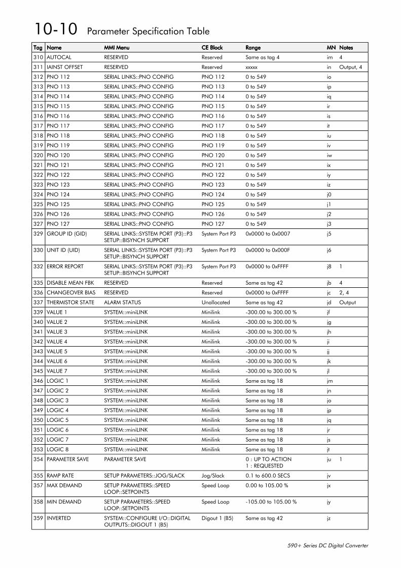
10-10 Parameter Specification Table
590+ Series DC Digital Converter
TagTagTagTag NameNameNameName MMI MenuMMI MenuMMI MenuMMI Menu CE BlockCE BlockCE BlockCE Block RangeRangeRangeRange MNMNMNMN NotesNotesNotesNotes
310 AUTOCAL RESERVED Reserved Same as tag 4 im 4
311 IAINST OFFSET RESERVED Reserved xxxxx in Output, 4
312 PNO 112 SERIAL LINKS::PNO CONFIG PNO 112 0 to 549 io
313 PNO 113 SERIAL LINKS::PNO CONFIG PNO 113 0 to 549 ip
314 PNO 114 SERIAL LINKS::PNO CONFIG PNO 114 0 to 549 iq
315 PNO 115 SERIAL LINKS::PNO CONFIG PNO 115 0 to 549 ir
316 PNO 116 SERIAL LINKS::PNO CONFIG PNO 116 0 to 549 is
317 PNO 117 SERIAL LINKS::PNO CONFIG PNO 117 0 to 549 it
318 PNO 118 SERIAL LINKS::PNO CONFIG PNO 118 0 to 549 iu
319 PNO 119 SERIAL LINKS::PNO CONFIG PNO 119 0 to 549 iv
320 PNO 120 SERIAL LINKS::PNO CONFIG PNO 120 0 to 549 iw
321 PNO 121 SERIAL LINKS::PNO CONFIG PNO 121 0 to 549 ix
322 PNO 122 SERIAL LINKS::PNO CONFIG PNO 122 0 to 549 iy
323 PNO 123 SERIAL LINKS::PNO CONFIG PNO 123 0 to 549 iz
324 PNO 124 SERIAL LINKS::PNO CONFIG PNO 124 0 to 549 j0
325 PNO 125 SERIAL LINKS::PNO CONFIG PNO 125 0 to 549 j1
326 PNO 126 SERIAL LINKS::PNO CONFIG PNO 126 0 to 549 j2
327 PNO 127 SERIAL LINKS::PNO CONFIG PNO 127 0 to 549 j3
329 GROUP ID (GID) SERIAL LINKS::SYSTEM PORT (P3)::P3SETUP::BISYNCH SUPPORT
System Port P3 0x0000 to 0x0007 j5
330 UNIT ID (UID) SERIAL LINKS::SYSTEM PORT (P3)::P3SETUP::BISYNCH SUPPORT
System Port P3 0x0000 to 0x000F j6
332 ERROR REPORT SERIAL LINKS::SYSTEM PORT (P3)::P3SETUP::BISYNCH SUPPORT
System Port P3 0x0000 to 0xFFFF j8 1
335 DISABLE MEAN FBK RESERVED Reserved Same as tag 42 jb 4
336 CHANGEOVER BIAS RESERVED Reserved 0x0000 to 0xFFFF jc 2, 4
337 THERMISTOR STATE ALARM STATUS Unallocated Same as tag 42 jd Output
339 VALUE 1 SYSTEM::miniLINK Minilink -300.00 to 300.00 % jf
340 VALUE 2 SYSTEM::miniLINK Minilink -300.00 to 300.00 % jg
341 VALUE 3 SYSTEM::miniLINK Minilink -300.00 to 300.00 % jh
342 VALUE 4 SYSTEM::miniLINK Minilink -300.00 to 300.00 % ji
343 VALUE 5 SYSTEM::miniLINK Minilink -300.00 to 300.00 % jj
344 VALUE 6 SYSTEM::miniLINK Minilink -300.00 to 300.00 % jk
345 VALUE 7 SYSTEM::miniLINK Minilink -300.00 to 300.00 % jl
346 LOGIC 1 SYSTEM::miniLINK Minilink Same as tag 18 jm
347 LOGIC 2 SYSTEM::miniLINK Minilink Same as tag 18 jn
348 LOGIC 3 SYSTEM::miniLINK Minilink Same as tag 18 jo
349 LOGIC 4 SYSTEM::miniLINK Minilink Same as tag 18 jp
350 LOGIC 5 SYSTEM::miniLINK Minilink Same as tag 18 jq
351 LOGIC 6 SYSTEM::miniLINK Minilink Same as tag 18 jr
352 LOGIC 7 SYSTEM::miniLINK Minilink Same as tag 18 js
353 LOGIC 8 SYSTEM::miniLINK Minilink Same as tag 18 jt
354 PARAMETER SAVE PARAMETER SAVE 0 : UP TO ACTION1 : REQUESTED
ju 1
355 RAMP RATE SETUP PARAMETERS::JOG/SLACK Jog/Slack 0.1 to 600.0 SECS jv
357 MAX DEMAND SETUP PARAMETERS::SPEEDLOOP::SETPOINTS
Speed Loop 0.00 to 105.00 % jx
358 MIN DEMAND SETUP PARAMETERS::SPEEDLOOP::SETPOINTS
Speed Loop -105.00 to 105.00 % jy
359 INVERTED SYSTEM::CONFIGURE I/O::DIGITALOUTPUTS::DIGOUT 1 (B5)
Digout 1 (B5) Same as tag 42 jz
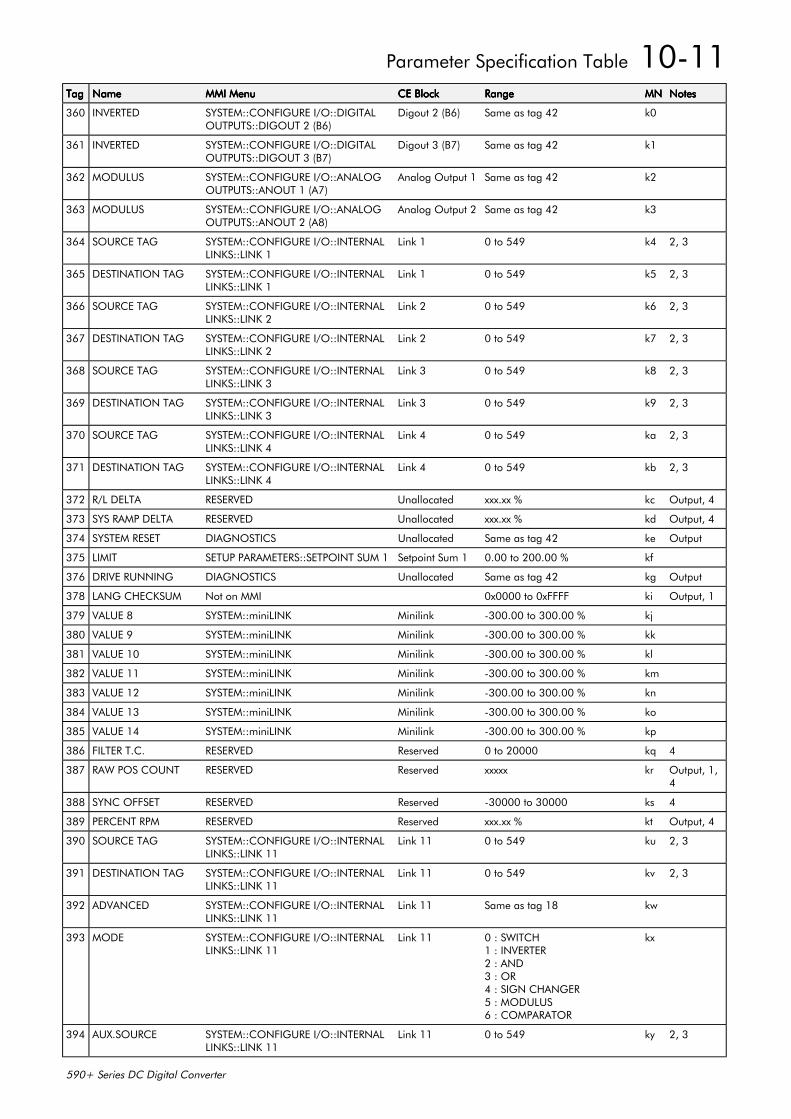
Parameter Specification Table 10-11
590+ Series DC Digital Converter
TagTagTagTag NameNameNameName MMI MenuMMI MenuMMI MenuMMI Menu CE BlockCE BlockCE BlockCE Block RangeRangeRangeRange MNMNMNMN NotesNotesNotesNotes
360 INVERTED SYSTEM::CONFIGURE I/O::DIGITALOUTPUTS::DIGOUT 2 (B6)
Digout 2 (B6) Same as tag 42 k0
361 INVERTED SYSTEM::CONFIGURE I/O::DIGITALOUTPUTS::DIGOUT 3 (B7)
Digout 3 (B7) Same as tag 42 k1
362 MODULUS SYSTEM::CONFIGURE I/O::ANALOGOUTPUTS::ANOUT 1 (A7)
Analog Output 1 Same as tag 42 k2
363 MODULUS SYSTEM::CONFIGURE I/O::ANALOGOUTPUTS::ANOUT 2 (A8)
Analog Output 2 Same as tag 42 k3
364 SOURCE TAG SYSTEM::CONFIGURE I/O::INTERNALLINKS::LINK 1
Link 1 0 to 549 k4 2, 3
365 DESTINATION TAG SYSTEM::CONFIGURE I/O::INTERNALLINKS::LINK 1
Link 1 0 to 549 k5 2, 3
366 SOURCE TAG SYSTEM::CONFIGURE I/O::INTERNALLINKS::LINK 2
Link 2 0 to 549 k6 2, 3
367 DESTINATION TAG SYSTEM::CONFIGURE I/O::INTERNALLINKS::LINK 2
Link 2 0 to 549 k7 2, 3
368 SOURCE TAG SYSTEM::CONFIGURE I/O::INTERNALLINKS::LINK 3
Link 3 0 to 549 k8 2, 3
369 DESTINATION TAG SYSTEM::CONFIGURE I/O::INTERNALLINKS::LINK 3
Link 3 0 to 549 k9 2, 3
370 SOURCE TAG SYSTEM::CONFIGURE I/O::INTERNALLINKS::LINK 4
Link 4 0 to 549 ka 2, 3
371 DESTINATION TAG SYSTEM::CONFIGURE I/O::INTERNALLINKS::LINK 4
Link 4 0 to 549 kb 2, 3
372 R/L DELTA RESERVED Unallocated xxx.xx % kc Output, 4
373 SYS RAMP DELTA RESERVED Unallocated xxx.xx % kd Output, 4
374 SYSTEM RESET DIAGNOSTICS Unallocated Same as tag 42 ke Output
375 LIMIT SETUP PARAMETERS::SETPOINT SUM 1 Setpoint Sum 1 0.00 to 200.00 % kf
376 DRIVE RUNNING DIAGNOSTICS Unallocated Same as tag 42 kg Output
378 LANG CHECKSUM Not on MMI 0x0000 to 0xFFFF ki Output, 1
379 VALUE 8 SYSTEM::miniLINK Minilink -300.00 to 300.00 % kj
380 VALUE 9 SYSTEM::miniLINK Minilink -300.00 to 300.00 % kk
381 VALUE 10 SYSTEM::miniLINK Minilink -300.00 to 300.00 % kl
382 VALUE 11 SYSTEM::miniLINK Minilink -300.00 to 300.00 % km
383 VALUE 12 SYSTEM::miniLINK Minilink -300.00 to 300.00 % kn
384 VALUE 13 SYSTEM::miniLINK Minilink -300.00 to 300.00 % ko
385 VALUE 14 SYSTEM::miniLINK Minilink -300.00 to 300.00 % kp
386 FILTER T.C. RESERVED Reserved 0 to 20000 kq 4
387 RAW POS COUNT RESERVED Reserved xxxxx kr Output, 1,4
388 SYNC OFFSET RESERVED Reserved -30000 to 30000 ks 4
389 PERCENT RPM RESERVED Reserved xxx.xx % kt Output, 4
390 SOURCE TAG SYSTEM::CONFIGURE I/O::INTERNALLINKS::LINK 11
Link 11 0 to 549 ku 2, 3
391 DESTINATION TAG SYSTEM::CONFIGURE I/O::INTERNALLINKS::LINK 11
Link 11 0 to 549 kv 2, 3
392 ADVANCED SYSTEM::CONFIGURE I/O::INTERNALLINKS::LINK 11
Link 11 Same as tag 18 kw
393 MODE SYSTEM::CONFIGURE I/O::INTERNALLINKS::LINK 11
Link 11 0 : SWITCH1 : INVERTER2 : AND3 : OR4 : SIGN CHANGER5 : MODULUS6 : COMPARATOR
kx
394 AUX.SOURCE SYSTEM::CONFIGURE I/O::INTERNALLINKS::LINK 11
Link 11 0 to 549 ky 2, 3
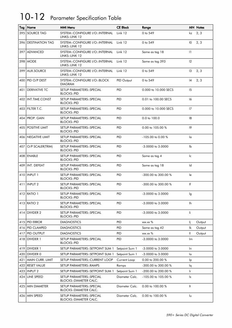
10-12 Parameter Specification Table
590+ Series DC Digital Converter
TagTagTagTag NameNameNameName MMI MenuMMI MenuMMI MenuMMI Menu CE BlockCE BlockCE BlockCE Block RangeRangeRangeRange MNMNMNMN NotesNotesNotesNotes
395 SOURCE TAG SYSTEM::CONFIGURE I/O::INTERNALLINKS::LINK 12
Link 12 0 to 549 kz 2, 3
396 DESTINATION TAG SYSTEM::CONFIGURE I/O::INTERNALLINKS::LINK 12
Link 12 0 to 549 l0 2, 3
397 ADVANCED SYSTEM::CONFIGURE I/O::INTERNALLINKS::LINK 12
Link 12 Same as tag 18 l1
398 MODE SYSTEM::CONFIGURE I/O::INTERNALLINKS::LINK 12
Link 12 Same as tag 393 l2
399 AUX.SOURCE SYSTEM::CONFIGURE I/O::INTERNALLINKS::LINK 12
Link 12 0 to 549 l3 2, 3
400 PID O/P DEST SYSTEM::CONFIGURE I/O::BLOCKDIAGRAM
PID Output 0 to 549 l4 2, 3
401 DERIVATIVE TC SETUP PARAMETERS::SPECIALBLOCKS::PID
PID 0.000 to 10.000 SECS l5
402 INT.TIME.CONST SETUP PARAMETERS::SPECIALBLOCKS::PID
PID 0.01 to 100.00 SECS l6
403 FILTER T.C. SETUP PARAMETERS::SPECIALBLOCKS::PID
PID 0.000 to 10.000 SECS l7
404 PROP. GAIN SETUP PARAMETERS::SPECIALBLOCKS::PID
PID 0.0 to 100.0 l8
405 POSITIVE LIMIT SETUP PARAMETERS::SPECIALBLOCKS::PID
PID 0.00 to 105.00 % l9
406 NEGATIVE LIMIT SETUP PARAMETERS::SPECIALBLOCKS::PID
PID -105.00 to 0.00 % la
407 O/P SCALER(TRIM) SETUP PARAMETERS::SPECIALBLOCKS::PID
PID -3.0000 to 3.0000 lb
408 ENABLE SETUP PARAMETERS::SPECIALBLOCKS::PID
PID Same as tag 4 lc
409 INT. DEFEAT SETUP PARAMETERS::SPECIALBLOCKS::PID
PID Same as tag 18 ld
410 INPUT 1 SETUP PARAMETERS::SPECIALBLOCKS::PID
PID -300.00 to 300.00 % le
411 INPUT 2 SETUP PARAMETERS::SPECIALBLOCKS::PID
PID -300.00 to 300.00 % lf
412 RATIO 1 SETUP PARAMETERS::SPECIALBLOCKS::PID
PID -3.0000 to 3.0000 lg
413 RATIO 2 SETUP PARAMETERS::SPECIALBLOCKS::PID
PID -3.0000 to 3.0000 lh
414 DIVIDER 2 SETUP PARAMETERS::SPECIALBLOCKS::PID
PID -3.0000 to 3.0000 li
415 PID ERROR DIAGNOSTICS PID xxx.xx % lj Output
416 PID CLAMPED DIAGNOSTICS PID Same as tag 42 lk Output
417 PID OUTPUT DIAGNOSTICS PID xxx.xx % ll Output
418 DIVIDER 1 SETUP PARAMETERS::SPECIALBLOCKS::PID
PID -3.0000 to 3.0000 lm
419 DIVIDER 1 SETUP PARAMETERS::SETPOINT SUM 1 Setpoint Sum 1 -3.0000 to 3.0000 ln
420 DIVIDER 0 SETUP PARAMETERS::SETPOINT SUM 1 Setpoint Sum 1 -3.0000 to 3.0000 lo
421 MAIN CURR. LIMIT SETUP PARAMETERS::CURRENT LOOP Current Loop 0.00 to 200.00 % lp
422 RESET VALUE SETUP PARAMETERS::RAMPS Ramps -300.00 to 300.00 % lq
423 INPUT 2 SETUP PARAMETERS::SETPOINT SUM 1 Setpoint Sum 1 -200.00 to 200.00 % lr
424 LINE SPEED SETUP PARAMETERS::SPECIALBLOCKS::DIAMETER CALC.
Diameter Calc. -105.00 to 105.00 % ls
425 MIN DIAMETER SETUP PARAMETERS::SPECIALBLOCKS::DIAMETER CALC.
Diameter Calc. 0.00 to 100.00 % lt
426 MIN SPEED SETUP PARAMETERS::SPECIALBLOCKS::DIAMETER CALC.
Diameter Calc. 0.00 to 100.00 % lu
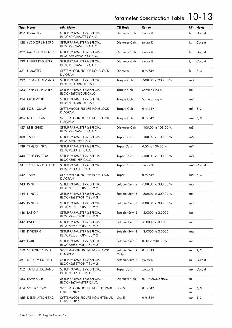
Parameter Specification Table 10-13
590+ Series DC Digital Converter
TagTagTagTag NameNameNameName MMI MenuMMI MenuMMI MenuMMI Menu CE BlockCE BlockCE BlockCE Block RangeRangeRangeRange MNMNMNMN NotesNotesNotesNotes
427 DIAMETER SETUP PARAMETERS::SPECIALBLOCKS::DIAMETER CALC.
Diameter Calc. xxx.xx % lv Output
428 MOD OF LINE SPD SETUP PARAMETERS::SPECIALBLOCKS::DIAMETER CALC.
Diameter Calc. xxx.xx % lw Output
429 MOD OF REEL SPD SETUP PARAMETERS::SPECIALBLOCKS::DIAMETER CALC.
Diameter Calc. xxx.xx % lx Output
430 UNFILT DIAMETER SETUP PARAMETERS::SPECIALBLOCKS::DIAMETER CALC.
Diameter Calc. xxx.xx % ly Output
431 DIAMETER SYSTEM::CONFIGURE I/O::BLOCKDIAGRAM
Diameter 0 to 549 lz 2, 3
432 TORQUE DEMAND SETUP PARAMETERS::SPECIALBLOCKS::TORQUE CALC.
Torque Calc. -200.00 to 200.00 % m0
433 TENSION ENABLE SETUP PARAMETERS::SPECIALBLOCKS::TORQUE CALC.
Torque Calc. Same as tag 4 m1
434 OVER WIND SETUP PARAMETERS::SPECIALBLOCKS::TORQUE CALC.
Torque Calc. Same as tag 4 m2
435 POS. I CLAMP SYSTEM::CONFIGURE I/O::BLOCKDIAGRAM
Torque Calc. 0 to 549 m3 2, 3
436 NEG. I CLAMP SYSTEM::CONFIGURE I/O::BLOCKDIAGRAM
Torque Calc. 0 to 549 m4 2, 3
437 REEL SPEED SETUP PARAMETERS::SPECIALBLOCKS::DIAMETER CALC.
Diameter Calc. -105.00 to 105.00 % m5
438 TAPER SETUP PARAMETERS::SPECIALBLOCKS::TAPER CALC.
Taper Calc. -100.00 to 100.00 % m6
439 TENSION SPT. SETUP PARAMETERS::SPECIALBLOCKS::TAPER CALC.
Taper Calc. 0.00 to 100.00 % m7
440 TENSION TRIM SETUP PARAMETERS::SPECIALBLOCKS::TAPER CALC.
Taper Calc. -100.00 to 100.00 % m8
441 TOT.TENS.DEMAND SETUP PARAMETERS::SPECIALBLOCKS::TAPER CALC.
Taper Calc. xxx.xx % m9 Output
442 TAPER SYSTEM::CONFIGURE I/O::BLOCKDIAGRAM
Taper 0 to 549 ma 2, 3
443 INPUT 1 SETUP PARAMETERS::SPECIALBLOCKS::SETPOINT SUM 2
Setpoint Sum 2 -300.00 to 300.00 % mb
444 INPUT 0 SETUP PARAMETERS::SPECIALBLOCKS::SETPOINT SUM 2
Setpoint Sum 2 -300.00 to 300.00 % mc
445 INPUT 2 SETUP PARAMETERS::SPECIALBLOCKS::SETPOINT SUM 2
Setpoint Sum 2 -300.00 to 300.00 % md
446 RATIO 1 SETUP PARAMETERS::SPECIALBLOCKS::SETPOINT SUM 2
Setpoint Sum 2 -3.0000 to 3.0000 me
447 RATIO 0 SETUP PARAMETERS::SPECIALBLOCKS::SETPOINT SUM 2
Setpoint Sum 2 -3.0000 to 3.0000 mf
448 DIVIDER 0 SETUP PARAMETERS::SPECIALBLOCKS::SETPOINT SUM 2
Setpoint Sum 2 -3.0000 to 3.0000 mg
449 LIMIT SETUP PARAMETERS::SPECIALBLOCKS::SETPOINT SUM 2
Setpoint Sum 2 0.00 to 200.00 % mh
450 SETPOINT SUM 2 SYSTEM::CONFIGURE I/O::BLOCKDIAGRAM
Setpoint Sum 2Output
0 to 549 mi 2, 3
451 SPT SUM OUTPUT SETUP PARAMETERS::SPECIALBLOCKS::SETPOINT SUM 2
Setpoint Sum 2 xxx.xx % mj Output
452 TAPERED DEMAND SETUP PARAMETERS::SPECIALBLOCKS::TAPER CALC.
Taper Calc. xxx.xx % mk Output
453 RAMP RATE SETUP PARAMETERS::SPECIALBLOCKS::DIAMETER CALC.
Diameter Calc. 0.1 to 600.0 SECS ml
454 SOURCE TAG SYSTEM::CONFIGURE I/O::INTERNALLINKS::LINK 5
Link 5 0 to 549 mm
2, 3
455 DESTINATION TAG SYSTEM::CONFIGURE I/O::INTERNALLINKS::LINK 5
Link 5 0 to 549 mn 2, 3
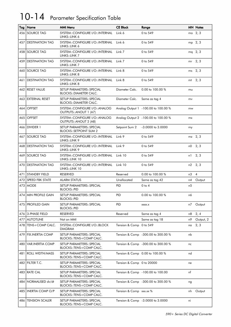
10-14 Parameter Specification Table
590+ Series DC Digital Converter
TagTagTagTag NameNameNameName MMI MenuMMI MenuMMI MenuMMI Menu CE BlockCE BlockCE BlockCE Block RangeRangeRangeRange MNMNMNMN NotesNotesNotesNotes
456 SOURCE TAG SYSTEM::CONFIGURE I/O::INTERNALLINKS::LINK 6
Link 6 0 to 549 mo 2, 3
457 DESTINATION TAG SYSTEM::CONFIGURE I/O::INTERNALLINKS::LINK 6
Link 6 0 to 549 mp 2, 3
458 SOURCE TAG SYSTEM::CONFIGURE I/O::INTERNALLINKS::LINK 7
Link 7 0 to 549 mq 2, 3
459 DESTINATION TAG SYSTEM::CONFIGURE I/O::INTERNALLINKS::LINK 7
Link 7 0 to 549 mr 2, 3
460 SOURCE TAG SYSTEM::CONFIGURE I/O::INTERNALLINKS::LINK 8
Link 8 0 to 549 ms 2, 3
461 DESTINATION TAG SYSTEM::CONFIGURE I/O::INTERNALLINKS::LINK 8
Link 8 0 to 549 mt 2, 3
462 RESET VALUE SETUP PARAMETERS::SPECIALBLOCKS::DIAMETER CALC.
Diameter Calc. 0.00 to 100.00 % mu
463 EXTERNAL RESET SETUP PARAMETERS::SPECIALBLOCKS::DIAMETER CALC.
Diameter Calc. Same as tag 4 mv
464 OFFSET SYSTEM::CONFIGURE I/O::ANALOGOUTPUTS::ANOUT 1 (A7)
Analog Output 1 -100.00 to 100.00 % mw
465 OFFSET SYSTEM::CONFIGURE I/O::ANALOGOUTPUTS::ANOUT 2 (A8)
Analog Output 2 -100.00 to 100.00 % mx
466 DIVIDER 1 SETUP PARAMETERS::SPECIALBLOCKS::SETPOINT SUM 2
Setpoint Sum 2 -3.0000 to 3.0000 my
467 SOURCE TAG SYSTEM::CONFIGURE I/O::INTERNALLINKS::LINK 9
Link 9 0 to 549 mz 2, 3
468 DESTINATION TAG SYSTEM::CONFIGURE I/O::INTERNALLINKS::LINK 9
Link 9 0 to 549 n0 2, 3
469 SOURCE TAG SYSTEM::CONFIGURE I/O::INTERNALLINKS::LINK 10
Link 10 0 to 549 n1 2, 3
470 DESTINATION TAG SYSTEM::CONFIGURE I/O::INTERNALLINKS::LINK 10
Link 10 0 to 549 n2 2, 3
471 STANDBY FIELD RESERVED Reserved 0.00 to 100.00 % n3 4
472 SPEED FBK STATE ALARM STATUS Unallocated Same as tag 42 n4 Output
473 MODE SETUP PARAMETERS::SPECIALBLOCKS::PID
PID 0 to 4 n5
474 MIN PROFILE GAIN SETUP PARAMETERS::SPECIALBLOCKS::PID
PID 0.00 to 100.00 % n6
475 PROFILED GAIN SETUP PARAMETERS::SPECIALBLOCKS::PID
PID xxxx.x n7 Output
476 3-PHASE FIELD RESERVED Reserved Same as tag 4 n8 2, 4
477 AUTOTUNE Not on MMI Same as tag 18 n9 Output, 2
478 TENS+COMP CALC. SYSTEM::CONFIGURE I/O::BLOCKDIAGRAM
Tension & Comp 0 to 549 na 2, 3
479 FIX.INERTIA COMP SETUP PARAMETERS::SPECIALBLOCKS::TENS+COMP CALC.
Tension & Comp -300.00 to 300.00 % nb
480 VAR.INERTIA COMP SETUP PARAMETERS::SPECIALBLOCKS::TENS+COMP CALC.
Tension & Comp -300.00 to 300.00 % nc
481 ROLL WIDTH/MASS SETUP PARAMETERS::SPECIALBLOCKS::TENS+COMP CALC.
Tension & Comp 0.00 to 100.00 % nd
482 FILTER T.C. SETUP PARAMETERS::SPECIALBLOCKS::TENS+COMP CALC.
Tension & Comp 0 to 20000 ne
483 RATE CAL SETUP PARAMETERS::SPECIALBLOCKS::TENS+COMP CALC.
Tension & Comp -100.00 to 100.00 nf
484 NORMALISED dv/dt SETUP PARAMETERS::SPECIALBLOCKS::TENS+COMP CALC.
Tension & Comp -300.00 to 300.00 % ng
485 INERTIA COMP O/P SETUP PARAMETERS::SPECIALBLOCKS::TENS+COMP CALC.
Tension & Comp xxx.xx % nh Output
486 TENSION SCALER SETUP PARAMETERS::SPECIALBLOCKS::TENS+COMP CALC.
Tension & Comp -3.0000 to 3.0000 ni
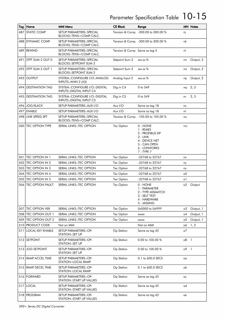
Parameter Specification Table 10-15
590+ Series DC Digital Converter
TagTagTagTag NameNameNameName MMI MenuMMI MenuMMI MenuMMI Menu CE BlockCE BlockCE BlockCE Block RangeRangeRangeRange MNMNMNMN NotesNotesNotesNotes
487 STATIC COMP SETUP PARAMETERS::SPECIALBLOCKS::TENS+COMP CALC.
Tension & Comp -300.00 to 300.00 % nj
488 DYNAMIC COMP SETUP PARAMETERS::SPECIALBLOCKS::TENS+COMP CALC.
Tension & Comp -300.00 to 300.00 % nk
489 REWIND SETUP PARAMETERS::SPECIALBLOCKS::TENS+COMP CALC.
Tension & Comp Same as tag 4 nl
491 STPT SUM 2 OUT 0 SETUP PARAMETERS::SPECIALBLOCKS::SETPOINT SUM 2
Setpoint Sum 2 xxx.xx % nn Output, 2
492 STPT SUM 2 OUT 1 SETUP PARAMETERS::SPECIALBLOCKS::SETPOINT SUM 2
Setpoint Sum 2 xxx.xx % no Output, 2
493 OUTPUT SYSTEM::CONFIGURE I/O::ANALOGINPUTS::ANIN 2 (A3)
Analog Input 2 xxx.xx % np Output, 2
494 DESTINATION TAG SYSTEM::CONFIGURE I/O::DIGITALINPUTS::DIGITAL INPUT C4
Dig in C4 0 to 549 nq 2, 3
495 DESTINATION TAG SYSTEM::CONFIGURE I/O::DIGITALINPUTS::DIGITAL INPUT C5
Dig in C5 0 to 549 nr 2, 3
496 JOG/SLACK SETUP PARAMETERS::AUX I/O Aux I/O Same as tag 18 ns
497 ENABLE SETUP PARAMETERS::AUX I/O Aux I/O Same as tag 18 nt
498 LINE SPEED SPT SETUP PARAMETERS::SPECIALBLOCKS::TENS+COMP CALC.
Tension & Comp -105.00 to 105.00 % nu
500 TEC OPTION TYPE SERIAL LINKS::TEC OPTION Tec Option 0 : NONE1 : RS4852 : PROFIBUS DP3 : LINK4 : DEVICE NET5 : CAN OPEN6 : LONWORKS7 : TYPE 7
nw
501 TEC OPTION IN 1 SERIAL LINKS::TEC OPTION Tec Option -32768 to 32767 nx
502 TEC OPTION IN 2 SERIAL LINKS::TEC OPTION Tec Option -32768 to 32767 ny
503 TEC OPTION IN 3 SERIAL LINKS::TEC OPTION Tec Option -32768 to 32767 nz
504 TEC OPTION IN 4 SERIAL LINKS::TEC OPTION Tec Option -32768 to 32767 o0
505 TEC OPTION IN 5 SERIAL LINKS::TEC OPTION Tec Option -32768 to 32767 o1
506 TEC OPTION FAULT SERIAL LINKS::TEC OPTION Tec Option 0 : NONE1 : PARAMETER2 : TYPE MISMATCH3 : SELF TEST4 : HARDWARE5 : MISSING
o2 Output
507 TEC OPTION VER SERIAL LINKS::TEC OPTION Tec Option 0x0000 to 0xFFFF o3 Output, 1
508 TEC OPTION OUT 1 SERIAL LINKS::TEC OPTION Tec Option xxxxx o4 Output, 1
509 TEC OPTION OUT 2 SERIAL LINKS::TEC OPTION Tec Option xxxxx o5 Output, 1
510 PRODUCT CODE Not on MMI Not on MMI o6 1, 2
511 LOCAL KEY ENABLE SETUP PARAMETERS::OP-STATION::SET UP
Op Station Same as tag 42 o7
512 SETPOINT SETUP PARAMETERS::OP-STATION::SET UP
Op Station 0.00 to 100.00 % o8 1
513 JOG SETPOINT SETUP PARAMETERS::OP-STATION::SET UP
Op Station 0.00 to 100.00 % o9 1
514 RAMP ACCEL TIME SETUP PARAMETERS::OP-STATION::LOCAL RAMP
Op Station 0.1 to 600.0 SECS oa
515 RAMP DECEL TIME SETUP PARAMETERS::OP-STATION::LOCAL RAMP
Op Station 0.1 to 600.0 SECS ob
516 FORWARD SETUP PARAMETERS::OP-STATION::START UP VALUES
Op Station Same as tag 42 oc
517 LOCAL SETUP PARAMETERS::OP-STATION::START UP VALUES
Op Station Same as tag 42 od
518 PROGRAM SETUP PARAMETERS::OP-STATION::START UP VALUES
Op Station Same as tag 42 oe
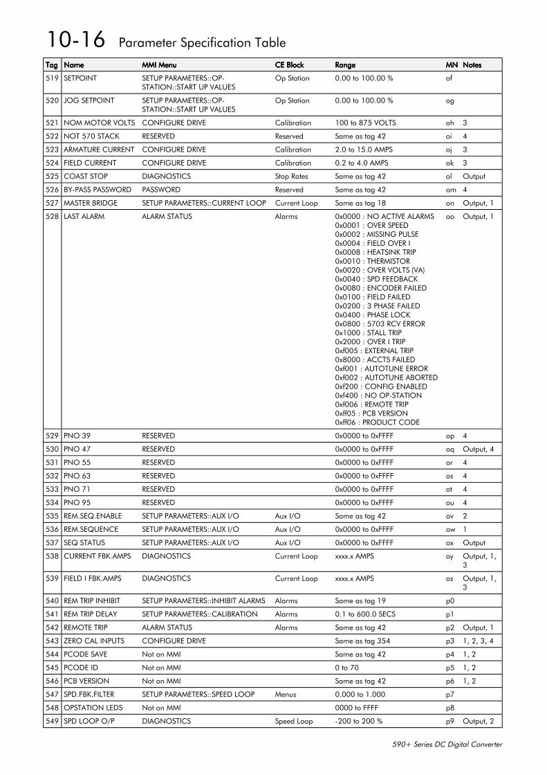
10-16 Parameter Specification Table
590+ Series DC Digital Converter
TagTagTagTag NameNameNameName MMI MenuMMI MenuMMI MenuMMI Menu CE BlockCE BlockCE BlockCE Block RangeRangeRangeRange MNMNMNMN NotesNotesNotesNotes
519 SETPOINT SETUP PARAMETERS::OP-STATION::START UP VALUES
Op Station 0.00 to 100.00 % of
520 JOG SETPOINT SETUP PARAMETERS::OP-STATION::START UP VALUES
Op Station 0.00 to 100.00 % og
521 NOM MOTOR VOLTS CONFIGURE DRIVE Calibration 100 to 875 VOLTS oh 3
522 NOT 570 STACK RESERVED Reserved Same as tag 42 oi 4
523 ARMATURE CURRENT CONFIGURE DRIVE Calibration 2.0 to 15.0 AMPS oj 3
524 FIELD CURRENT CONFIGURE DRIVE Calibration 0.2 to 4.0 AMPS ok 3
525 COAST STOP DIAGNOSTICS Stop Rates Same as tag 42 ol Output
526 BY-PASS PASSWORD PASSWORD Reserved Same as tag 42 om 4
527 MASTER BRIDGE SETUP PARAMETERS::CURRENT LOOP Current Loop Same as tag 18 on Output, 1
528 LAST ALARM ALARM STATUS Alarms 0x0000 : NO ACTIVE ALARMS0x0001 : OVER SPEED0x0002 : MISSING PULSE0x0004 : FIELD OVER I0x0008 : HEATSINK TRIP0x0010 : THERMISTOR0x0020 : OVER VOLTS (VA)0x0040 : SPD FEEDBACK0x0080 : ENCODER FAILED0x0100 : FIELD FAILED0x0200 : 3 PHASE FAILED0x0400 : PHASE LOCK0x0800 : 5703 RCV ERROR0x1000 : STALL TRIP0x2000 : OVER I TRIP0xf005 : EXTERNAL TRIP0x8000 : ACCTS FAILED0xf001 : AUTOTUNE ERROR0xf002 : AUTOTUNE ABORTED0xf200 : CONFIG ENABLED0xf400 : NO OP-STATION0xf006 : REMOTE TRIP0xff05 : PCB VERSION0xff06 : PRODUCT CODE
oo Output, 1
529 PNO 39 RESERVED 0x0000 to 0xFFFF op 4
530 PNO 47 RESERVED 0x0000 to 0xFFFF oq Output, 4
531 PNO 55 RESERVED 0x0000 to 0xFFFF or 4
532 PNO 63 RESERVED 0x0000 to 0xFFFF os 4
533 PNO 71 RESERVED 0x0000 to 0xFFFF ot 4
534 PNO 95 RESERVED 0x0000 to 0xFFFF ou 4
535 REM.SEQ.ENABLE SETUP PARAMETERS::AUX I/O Aux I/O Same as tag 42 ov 2
536 REM.SEQUENCE SETUP PARAMETERS::AUX I/O Aux I/O 0x0000 to 0xFFFF ow 1
537 SEQ STATUS SETUP PARAMETERS::AUX I/O Aux I/O 0x0000 to 0xFFFF ox Output
538 CURRENT FBK.AMPS DIAGNOSTICS Current Loop xxxx.x AMPS oy Output, 1,3
539 FIELD I FBK.AMPS DIAGNOSTICS Current Loop xxxx.x AMPS oz Output, 1,3
540 REM TRIP INHIBIT SETUP PARAMETERS::INHIBIT ALARMS Alarms Same as tag 19 p0
541 REM TRIP DELAY SETUP PARAMETERS::CALIBRATION Alarms 0.1 to 600.0 SECS p1
542 REMOTE TRIP ALARM STATUS Alarms Same as tag 42 p2 Output, 1
543 ZERO CAL INPUTS CONFIGURE DRIVE Same as tag 354 p3 1, 2, 3, 4
544 PCODE SAVE Not on MMI Same as tag 42 p4 1, 2
545 PCODE ID Not on MMI 0 to 70 p5 1, 2
546 PCB VERSION Not on MMI Same as tag 42 p6 1, 2
547 SPD.FBK.FILTER SETUP PARAMETERS::SPEED LOOP Menus 0.000 to 1.000 p7
548 OPSTATION LEDS Not on MMI 0000 to FFFF p8
549 SPD LOOP O/P DIAGNOSTICS Speed Loop -200 to 200 % p9 Output, 2

Parameter Specification Table 10-17
590+ Series DC Digital Converter
TagTagTagTag NameNameNameName MMI MenuMMI MenuMMI MenuMMI Menu CE BlockCE BlockCE BlockCE Block RangeRangeRangeRange MNMNMNMN NotesNotesNotesNotes
550 ENABLE 12 PULSE RESERVED 0 to 2 pa
551 MASTER BRIDGE RESERVED FALSE / TRUE pb
552 SLAVE BRIDGE RESERVED FALSE / TRUE pc
553 MAX BS DEAD TIME RESERVED 1 to 6000 pd

10-18 Parameter Specification Table
590+ Series DC Digital Converter
Parameter Table: MMI Menu Order
1 FACTORY DEFAULTS2 |__MENU3 | |__DIAGNOSTICSDIAGNOSTICSDIAGNOSTICSDIAGNOSTICS4 | | |__[089] SPEED DEMAND4 | | |__[207] SPEED FEEDBACK4 | | |__[297] SPEED ERROR4 | | |__[549] SPD LOOP OUTPUT4 | | |__[299] CURRENT DEMAND4 | | |__[298] CURRENT FEEDBACK4 | | |__[538] CURRENT FBK.AMPS4 | | |__[065] IaFbk UNFILTERED4 | | |__[066] IaDmd UNFILTERED4 | | |__[087] POS. I CLAMP4 | | |__[088] NEG. I CLAMP4 | | |__[067] ACTUAL POS I LIM4 | | |__[061] ACTUAL NEG I LIM4 | | |__[203] INVERSE TIME O/P Reserved4 | | |__[042] AT CURRENT LIMIT4 | | |__[077] AT ZERO SPEED4 | | |__[078] AT ZERO SETPOINT4 | | |__[079] AT STANDSTILL4 | | |__[113] RAMPING4 | | |__[080] PROGRAM STOP4 | | |__[525] COAST STOP4 | | |__[082] DRIVE START4 | | |__[084] DRIVE ENABLE4 | | |__[212] OPERATING MODE4 | | |__[169] FIELD ENABLED4 | | |__[183] FIELD DEMAND4 | | |__[300] FIELD I FBK.4 | | |__[539] FIELD I FBK.AMPS4 | | |__[181] RAW FIELD FBK4 | | |__[184] FLD.FIRING ANGLE4 | | |__[050] ANIN 1 (A2)4 | | |__[051] ANIN 2 (A3)4 | | |__[052] ANIN 3 (A4)4 | | |__[053] ANIN 4 (A5)4 | | |__[054] ANIN 5 (A6)4 | | |__[055] ANOUT 1 (A7)4 | | |__[056] ANOUT 2 (A8)4 | | |__[068] START (C3)4 | | |__[069] DIGITAL INPUT C44 | | |__[070] DIGITAL INPUT C54 | | |__[071] DIGIN 1 (C6)4 | | |__[072] DIGIN 2 (C7)4 | | |__[073] DIGIN 3 (C8)4 | | |__[074] DIGOUT 1 (B5)4 | | |__[075] DIGOUT 2 (B6)4 | | |__[076] DIGOUT 3 (B7)4 | | |__[264] RAISE/LOWER O/P4 | | |__[417] PID OUTPUT4 | | |__[416] PID CLAMPED4 | | |__[415] PID ERROR4 | | |__[086] SPT SUM OUTPUT4 | | |__[085] RAMP OUTPUT4 | | |__[063] SPEED SETPOINT4 | | |__[057] TERMINAL VOLTS4 | | |__[060] BACK EMF4 | | |__[308] TACH INPUT4 | | |__[058] UNFIL.TACH INPUT4 | | |__[206] ENCODER4 | | |__[059] UNFIL.ENCODER4 | | |__[062] UNFIL.SPD.FBK4 | | |__[064] UNFIL.SPD.ERROR
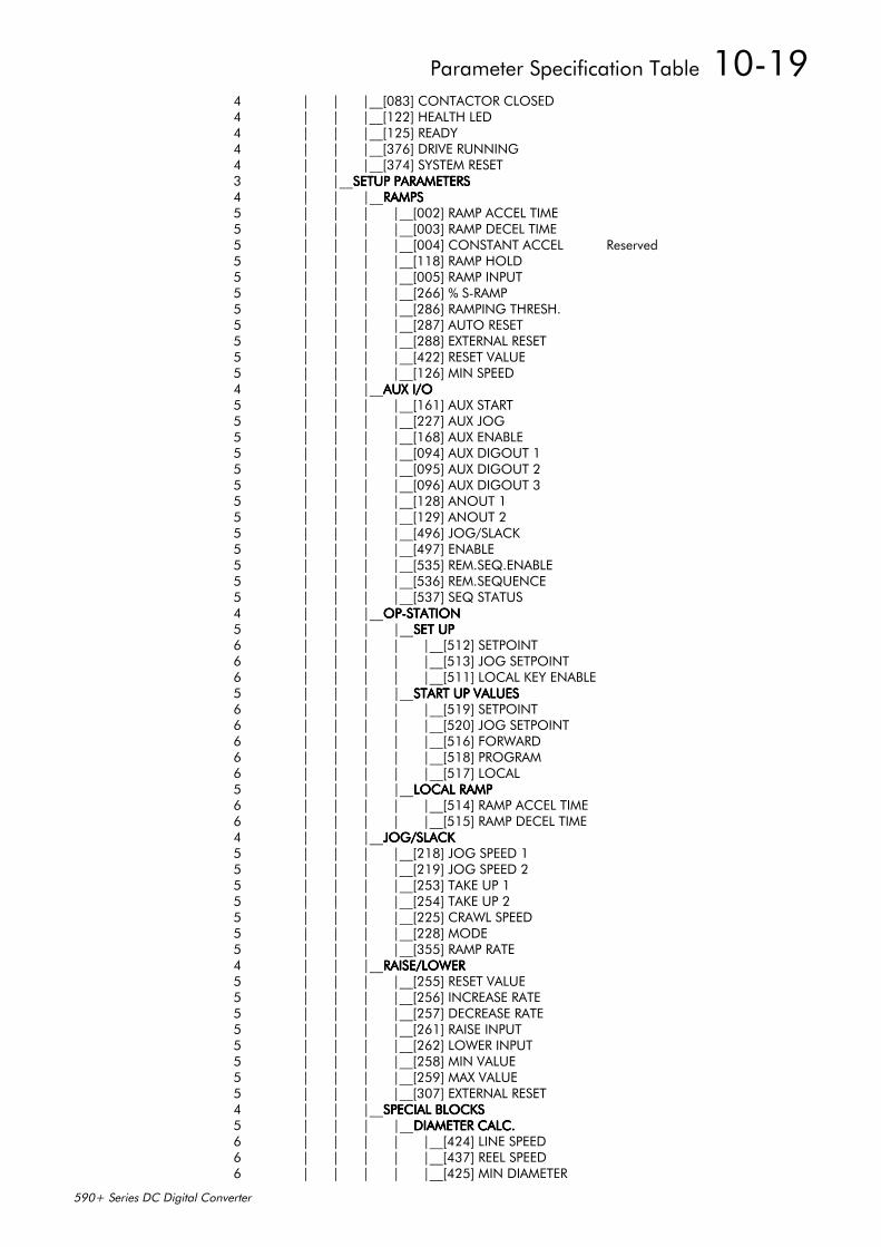
Parameter Specification Table 10-19
590+ Series DC Digital Converter
4 | | |__[083] CONTACTOR CLOSED4 | | |__[122] HEALTH LED4 | | |__[125] READY4 | | |__[376] DRIVE RUNNING4 | | |__[374] SYSTEM RESET3 | |__SETUP PARAMETERSSETUP PARAMETERSSETUP PARAMETERSSETUP PARAMETERS4 | | |__RAMPSRAMPSRAMPSRAMPS5 | | | |__[002] RAMP ACCEL TIME5 | | | |__[003] RAMP DECEL TIME5 | | | |__[004] CONSTANT ACCEL Reserved5 | | | |__[118] RAMP HOLD5 | | | |__[005] RAMP INPUT5 | | | |__[266] % S-RAMP5 | | | |__[286] RAMPING THRESH.5 | | | |__[287] AUTO RESET5 | | | |__[288] EXTERNAL RESET5 | | | |__[422] RESET VALUE5 | | | |__[126] MIN SPEED4 | | |__AUX I/OAUX I/OAUX I/OAUX I/O5 | | | |__[161] AUX START5 | | | |__[227] AUX JOG5 | | | |__[168] AUX ENABLE5 | | | |__[094] AUX DIGOUT 15 | | | |__[095] AUX DIGOUT 25 | | | |__[096] AUX DIGOUT 35 | | | |__[128] ANOUT 15 | | | |__[129] ANOUT 25 | | | |__[496] JOG/SLACK5 | | | |__[497] ENABLE5 | | | |__[535] REM.SEQ.ENABLE5 | | | |__[536] REM.SEQUENCE5 | | | |__[537] SEQ STATUS4 | | |__OP-STATIONOP-STATIONOP-STATIONOP-STATION5 | | | |__SET UPSET UPSET UPSET UP6 | | | | |__[512] SETPOINT6 | | | | |__[513] JOG SETPOINT6 | | | | |__[511] LOCAL KEY ENABLE5 | | | |__START UP VALUESSTART UP VALUESSTART UP VALUESSTART UP VALUES6 | | | | |__[519] SETPOINT6 | | | | |__[520] JOG SETPOINT6 | | | | |__[516] FORWARD6 | | | | |__[518] PROGRAM6 | | | | |__[517] LOCAL5 | | | |__LOCAL RAMPLOCAL RAMPLOCAL RAMPLOCAL RAMP6 | | | | |__[514] RAMP ACCEL TIME6 | | | | |__[515] RAMP DECEL TIME4 | | |__JOG/SLACKJOG/SLACKJOG/SLACKJOG/SLACK5 | | | |__[218] JOG SPEED 15 | | | |__[219] JOG SPEED 25 | | | |__[253] TAKE UP 15 | | | |__[254] TAKE UP 25 | | | |__[225] CRAWL SPEED5 | | | |__[228] MODE5 | | | |__[355] RAMP RATE4 | | |__RAISE/LOWERRAISE/LOWERRAISE/LOWERRAISE/LOWER5 | | | |__[255] RESET VALUE5 | | | |__[256] INCREASE RATE5 | | | |__[257] DECREASE RATE5 | | | |__[261] RAISE INPUT5 | | | |__[262] LOWER INPUT5 | | | |__[258] MIN VALUE5 | | | |__[259] MAX VALUE5 | | | |__[307] EXTERNAL RESET4 | | |__SPECIAL BLOCKSSPECIAL BLOCKSSPECIAL BLOCKSSPECIAL BLOCKS5 | | | |__DIAMETER CALC.DIAMETER CALC.DIAMETER CALC.DIAMETER CALC.6 | | | | |__[424] LINE SPEED6 | | | | |__[437] REEL SPEED6 | | | | |__[425] MIN DIAMETER
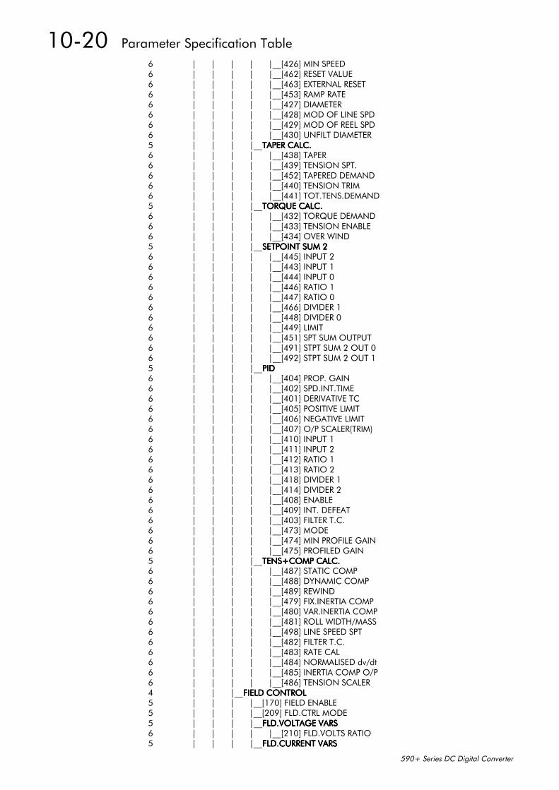
10-20 Parameter Specification Table
590+ Series DC Digital Converter
6 | | | | |__[426] MIN SPEED6 | | | | |__[462] RESET VALUE6 | | | | |__[463] EXTERNAL RESET6 | | | | |__[453] RAMP RATE6 | | | | |__[427] DIAMETER6 | | | | |__[428] MOD OF LINE SPD6 | | | | |__[429] MOD OF REEL SPD6 | | | | |__[430] UNFILT DIAMETER5 | | | |__TAPER CALC.TAPER CALC.TAPER CALC.TAPER CALC.6 | | | | |__[438] TAPER6 | | | | |__[439] TENSION SPT.6 | | | | |__[452] TAPERED DEMAND6 | | | | |__[440] TENSION TRIM6 | | | | |__[441] TOT.TENS.DEMAND5 | | | |__TORQUE CALC.TORQUE CALC.TORQUE CALC.TORQUE CALC.6 | | | | |__[432] TORQUE DEMAND6 | | | | |__[433] TENSION ENABLE6 | | | | |__[434] OVER WIND5 | | | |__SETPOINT SUM 2SETPOINT SUM 2SETPOINT SUM 2SETPOINT SUM 26 | | | | |__[445] INPUT 26 | | | | |__[443] INPUT 16 | | | | |__[444] INPUT 06 | | | | |__[446] RATIO 16 | | | | |__[447] RATIO 06 | | | | |__[466] DIVIDER 16 | | | | |__[448] DIVIDER 06 | | | | |__[449] LIMIT6 | | | | |__[451] SPT SUM OUTPUT6 | | | | |__[491] STPT SUM 2 OUT 06 | | | | |__[492] STPT SUM 2 OUT 15 | | | |__PIDPIDPIDPID6 | | | | |__[404] PROP. GAIN6 | | | | |__[402] SPD.INT.TIME6 | | | | |__[401] DERIVATIVE TC6 | | | | |__[405] POSITIVE LIMIT6 | | | | |__[406] NEGATIVE LIMIT6 | | | | |__[407] O/P SCALER(TRIM)6 | | | | |__[410] INPUT 16 | | | | |__[411] INPUT 26 | | | | |__[412] RATIO 16 | | | | |__[413] RATIO 26 | | | | |__[418] DIVIDER 16 | | | | |__[414] DIVIDER 26 | | | | |__[408] ENABLE6 | | | | |__[409] INT. DEFEAT6 | | | | |__[403] FILTER T.C.6 | | | | |__[473] MODE6 | | | | |__[474] MIN PROFILE GAIN6 | | | | |__[475] PROFILED GAIN5 | | | |__TENS+COMP CALC.TENS+COMP CALC.TENS+COMP CALC.TENS+COMP CALC.6 | | | | |__[487] STATIC COMP6 | | | | |__[488] DYNAMIC COMP6 | | | | |__[489] REWIND6 | | | | |__[479] FIX.INERTIA COMP6 | | | | |__[480] VAR.INERTIA COMP6 | | | | |__[481] ROLL WIDTH/MASS6 | | | | |__[498] LINE SPEED SPT6 | | | | |__[482] FILTER T.C.6 | | | | |__[483] RATE CAL6 | | | | |__[484] NORMALISED dv/dt6 | | | | |__[485] INERTIA COMP O/P6 | | | | |__[486] TENSION SCALER4 | | |__FIELD CONTROLFIELD CONTROLFIELD CONTROLFIELD CONTROL5 | | | |__[170] FIELD ENABLE5 | | | |__[209] FLD.CTRL MODE5 | | | |__FLD.VOLTAGE VARSFLD.VOLTAGE VARSFLD.VOLTAGE VARSFLD.VOLTAGE VARS6 | | | | |__[210] FLD.VOLTS RATIO5 | | | |__FLD.CURRENT VARSFLD.CURRENT VARSFLD.CURRENT VARSFLD.CURRENT VARS
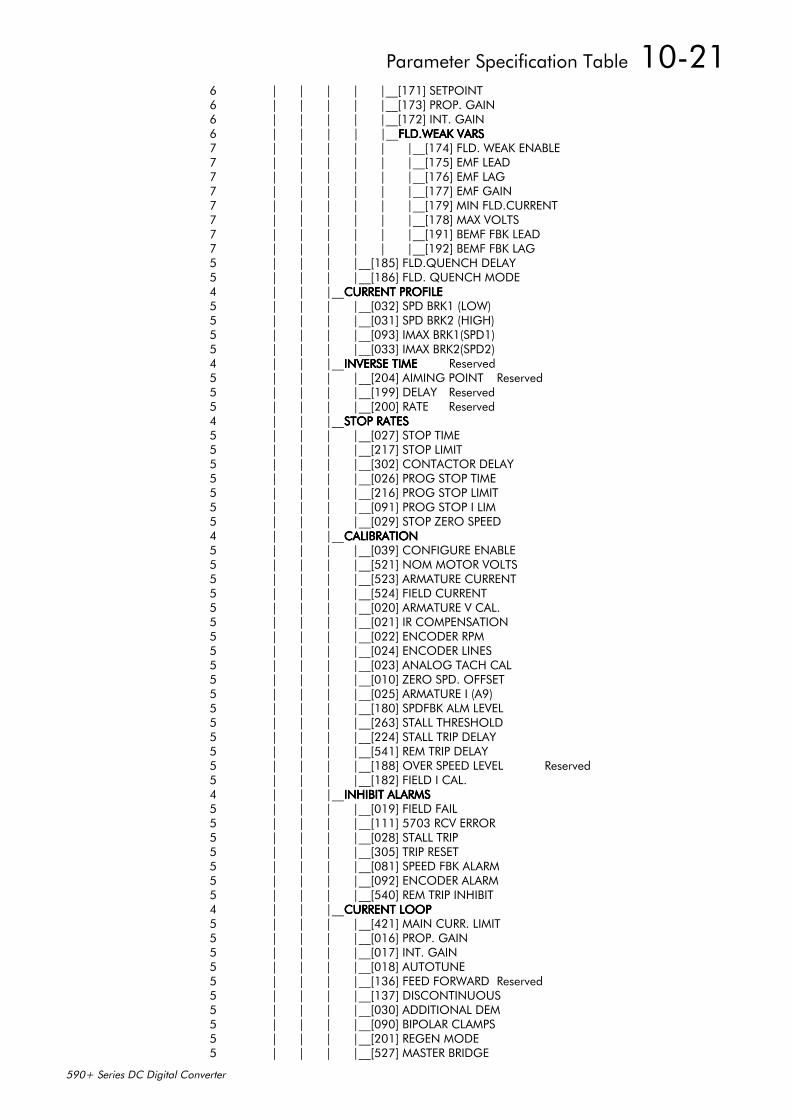
Parameter Specification Table 10-21
590+ Series DC Digital Converter
6 | | | | |__[171] SETPOINT6 | | | | |__[173] PROP. GAIN6 | | | | |__[172] INT. GAIN6 | | | | |__FLD.WEAK VARSFLD.WEAK VARSFLD.WEAK VARSFLD.WEAK VARS7 | | | | | |__[174] FLD. WEAK ENABLE7 | | | | | |__[175] EMF LEAD7 | | | | | |__[176] EMF LAG7 | | | | | |__[177] EMF GAIN7 | | | | | |__[179] MIN FLD.CURRENT7 | | | | | |__[178] MAX VOLTS7 | | | | | |__[191] BEMF FBK LEAD7 | | | | | |__[192] BEMF FBK LAG5 | | | |__[185] FLD.QUENCH DELAY5 | | | |__[186] FLD. QUENCH MODE4 | | |__CURRENT PROFILECURRENT PROFILECURRENT PROFILECURRENT PROFILE5 | | | |__[032] SPD BRK1 (LOW)5 | | | |__[031] SPD BRK2 (HIGH)5 | | | |__[093] IMAX BRK1(SPD1)5 | | | |__[033] IMAX BRK2(SPD2)4 | | |__INVERSE TIMEINVERSE TIMEINVERSE TIMEINVERSE TIME Reserved5 | | | |__[204] AIMING POINT Reserved5 | | | |__[199] DELAY Reserved5 | | | |__[200] RATE Reserved4 | | |__STOP RATESSTOP RATESSTOP RATESSTOP RATES5 | | | |__[027] STOP TIME5 | | | |__[217] STOP LIMIT5 | | | |__[302] CONTACTOR DELAY5 | | | |__[026] PROG STOP TIME5 | | | |__[216] PROG STOP LIMIT5 | | | |__[091] PROG STOP I LIM5 | | | |__[029] STOP ZERO SPEED4 | | |__CALIBRATIONCALIBRATIONCALIBRATIONCALIBRATION5 | | | |__[039] CONFIGURE ENABLE5 | | | |__[521] NOM MOTOR VOLTS5 | | | |__[523] ARMATURE CURRENT5 | | | |__[524] FIELD CURRENT5 | | | |__[020] ARMATURE V CAL.5 | | | |__[021] IR COMPENSATION5 | | | |__[022] ENCODER RPM5 | | | |__[024] ENCODER LINES5 | | | |__[023] ANALOG TACH CAL5 | | | |__[010] ZERO SPD. OFFSET5 | | | |__[025] ARMATURE I (A9)5 | | | |__[180] SPDFBK ALM LEVEL5 | | | |__[263] STALL THRESHOLD5 | | | |__[224] STALL TRIP DELAY5 | | | |__[541] REM TRIP DELAY5 | | | |__[188] OVER SPEED LEVEL Reserved5 | | | |__[182] FIELD I CAL.4 | | |__INHIBIT ALARMSINHIBIT ALARMSINHIBIT ALARMSINHIBIT ALARMS5 | | | |__[019] FIELD FAIL5 | | | |__[111] 5703 RCV ERROR5 | | | |__[028] STALL TRIP5 | | | |__[305] TRIP RESET5 | | | |__[081] SPEED FBK ALARM5 | | | |__[092] ENCODER ALARM5 | | | |__[540] REM TRIP INHIBIT4 | | |__CURRENT LOOPCURRENT LOOPCURRENT LOOPCURRENT LOOP5 | | | |__[421] MAIN CURR. LIMIT5 | | | |__[016] PROP. GAIN5 | | | |__[017] INT. GAIN5 | | | |__[018] AUTOTUNE5 | | | |__[136] FEED FORWARD Reserved5 | | | |__[137] DISCONTINUOUS5 | | | |__[030] ADDITIONAL DEM5 | | | |__[090] BIPOLAR CLAMPS5 | | | |__[201] REGEN MODE5 | | | |__[527] MASTER BRIDGE
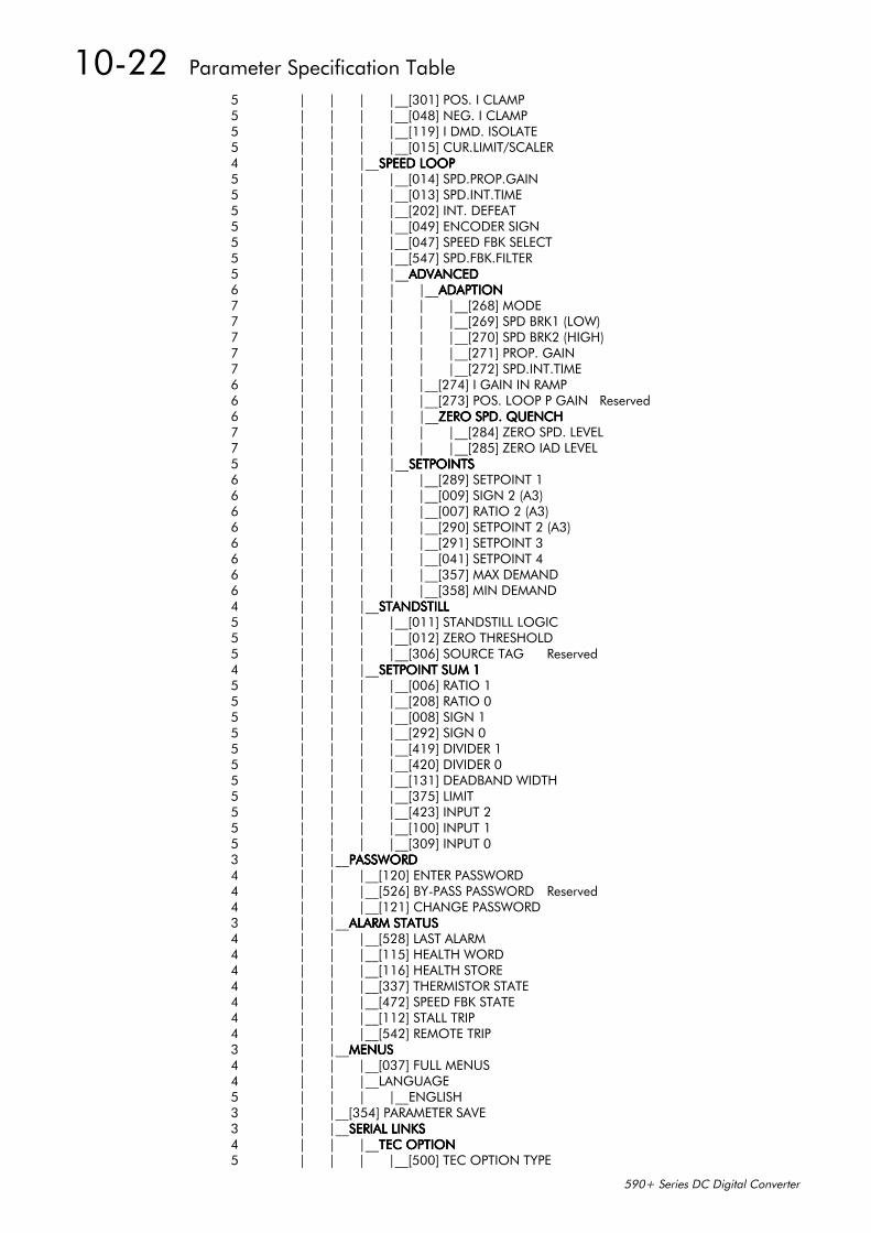
10-22 Parameter Specification Table
590+ Series DC Digital Converter
5 | | | |__[301] POS. I CLAMP5 | | | |__[048] NEG. I CLAMP5 | | | |__[119] I DMD. ISOLATE5 | | | |__[015] CUR.LIMIT/SCALER4 | | |__SPEED LOOPSPEED LOOPSPEED LOOPSPEED LOOP5 | | | |__[014] SPD.PROP.GAIN5 | | | |__[013] SPD.INT.TIME5 | | | |__[202] INT. DEFEAT5 | | | |__[049] ENCODER SIGN5 | | | |__[047] SPEED FBK SELECT5 | | | |__[547] SPD.FBK.FILTER5 | | | |__ADVANCEDADVANCEDADVANCEDADVANCED6 | | | | |__ADAPTIONADAPTIONADAPTIONADAPTION7 | | | | | |__[268] MODE7 | | | | | |__[269] SPD BRK1 (LOW)7 | | | | | |__[270] SPD BRK2 (HIGH)7 | | | | | |__[271] PROP. GAIN7 | | | | | |__[272] SPD.INT.TIME6 | | | | |__[274] I GAIN IN RAMP6 | | | | |__[273] POS. LOOP P GAIN Reserved6 | | | | |__ZERO SPD. QUENCHZERO SPD. QUENCHZERO SPD. QUENCHZERO SPD. QUENCH7 | | | | | |__[284] ZERO SPD. LEVEL7 | | | | | |__[285] ZERO IAD LEVEL5 | | | |__SETPOINTSSETPOINTSSETPOINTSSETPOINTS6 | | | | |__[289] SETPOINT 16 | | | | |__[009] SIGN 2 (A3)6 | | | | |__[007] RATIO 2 (A3)6 | | | | |__[290] SETPOINT 2 (A3)6 | | | | |__[291] SETPOINT 36 | | | | |__[041] SETPOINT 46 | | | | |__[357] MAX DEMAND6 | | | | |__[358] MIN DEMAND4 | | |__STANDSTILLSTANDSTILLSTANDSTILLSTANDSTILL5 | | | |__[011] STANDSTILL LOGIC5 | | | |__[012] ZERO THRESHOLD5 | | | |__[306] SOURCE TAG Reserved4 | | |__SETPOINT SUM 1SETPOINT SUM 1SETPOINT SUM 1SETPOINT SUM 15 | | | |__[006] RATIO 15 | | | |__[208] RATIO 05 | | | |__[008] SIGN 15 | | | |__[292] SIGN 05 | | | |__[419] DIVIDER 15 | | | |__[420] DIVIDER 05 | | | |__[131] DEADBAND WIDTH5 | | | |__[375] LIMIT5 | | | |__[423] INPUT 25 | | | |__[100] INPUT 15 | | | |__[309] INPUT 03 | |__PASSWORDPASSWORDPASSWORDPASSWORD4 | | |__[120] ENTER PASSWORD4 | | |__[526] BY-PASS PASSWORD Reserved4 | | |__[121] CHANGE PASSWORD3 | |__ALARM STATUSALARM STATUSALARM STATUSALARM STATUS4 | | |__[528] LAST ALARM4 | | |__[115] HEALTH WORD4 | | |__[116] HEALTH STORE4 | | |__[337] THERMISTOR STATE4 | | |__[472] SPEED FBK STATE4 | | |__[112] STALL TRIP4 | | |__[542] REMOTE TRIP3 | |__MENUSMENUSMENUSMENUS4 | | |__[037] FULL MENUS4 | | |__LANGUAGE5 | | | |__ENGLISH3 | |__[354] PARAMETER SAVE3 | |__SERIAL LINKSSERIAL LINKSSERIAL LINKSSERIAL LINKS4 | | |__TEC OPTIONTEC OPTIONTEC OPTIONTEC OPTION5 | | | |__[500] TEC OPTION TYPE
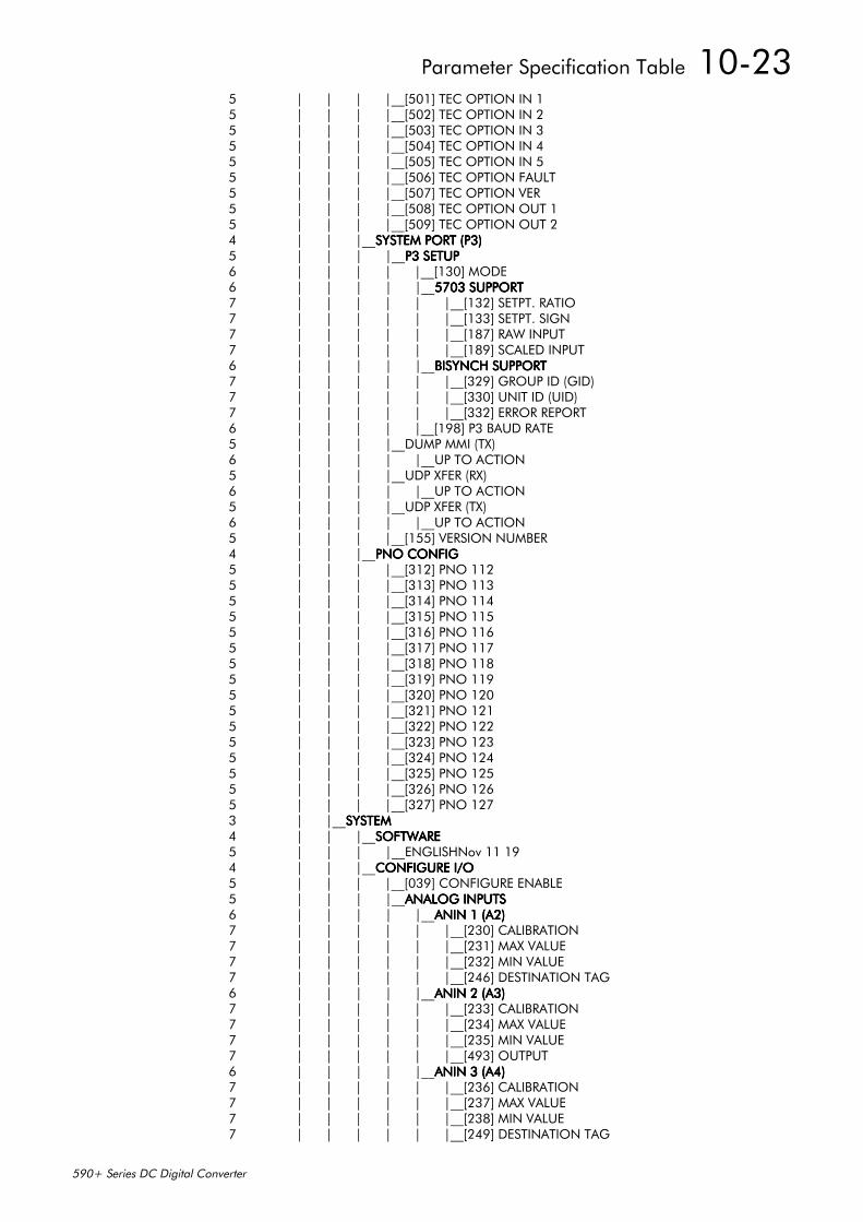
Parameter Specification Table 10-23
590+ Series DC Digital Converter
5 | | | |__[501] TEC OPTION IN 15 | | | |__[502] TEC OPTION IN 25 | | | |__[503] TEC OPTION IN 35 | | | |__[504] TEC OPTION IN 45 | | | |__[505] TEC OPTION IN 55 | | | |__[506] TEC OPTION FAULT5 | | | |__[507] TEC OPTION VER5 | | | |__[508] TEC OPTION OUT 15 | | | |__[509] TEC OPTION OUT 24 | | |__SYSTEM PORT (P3)SYSTEM PORT (P3)SYSTEM PORT (P3)SYSTEM PORT (P3)5 | | | |__P3 SETUPP3 SETUPP3 SETUPP3 SETUP6 | | | | |__[130] MODE6 | | | | |__5703 SUPPORT5703 SUPPORT5703 SUPPORT5703 SUPPORT7 | | | | | |__[132] SETPT. RATIO7 | | | | | |__[133] SETPT. SIGN7 | | | | | |__[187] RAW INPUT7 | | | | | |__[189] SCALED INPUT6 | | | | |__BISYNCH SUPPORTBISYNCH SUPPORTBISYNCH SUPPORTBISYNCH SUPPORT7 | | | | | |__[329] GROUP ID (GID)7 | | | | | |__[330] UNIT ID (UID)7 | | | | | |__[332] ERROR REPORT6 | | | | |__[198] P3 BAUD RATE5 | | | |__DUMP MMI (TX)6 | | | | |__UP TO ACTION5 | | | |__UDP XFER (RX)6 | | | | |__UP TO ACTION5 | | | |__UDP XFER (TX)6 | | | | |__UP TO ACTION5 | | | |__[155] VERSION NUMBER4 | | |__PNO CONFIGPNO CONFIGPNO CONFIGPNO CONFIG5 | | | |__[312] PNO 1125 | | | |__[313] PNO 1135 | | | |__[314] PNO 1145 | | | |__[315] PNO 1155 | | | |__[316] PNO 1165 | | | |__[317] PNO 1175 | | | |__[318] PNO 1185 | | | |__[319] PNO 1195 | | | |__[320] PNO 1205 | | | |__[321] PNO 1215 | | | |__[322] PNO 1225 | | | |__[323] PNO 1235 | | | |__[324] PNO 1245 | | | |__[325] PNO 1255 | | | |__[326] PNO 1265 | | | |__[327] PNO 1273 | |__SYSTEMSYSTEMSYSTEMSYSTEM4 | | |__SOFTWARESOFTWARESOFTWARESOFTWARE5 | | | |__ENGLISHNov 11 194 | | |__CONFIGURE I/OCONFIGURE I/OCONFIGURE I/OCONFIGURE I/O5 | | | |__[039] CONFIGURE ENABLE5 | | | |__ANALOG INPUTSANALOG INPUTSANALOG INPUTSANALOG INPUTS6 | | | | |__ANIN 1 (A2)ANIN 1 (A2)ANIN 1 (A2)ANIN 1 (A2)7 | | | | | |__[230] CALIBRATION7 | | | | | |__[231] MAX VALUE7 | | | | | |__[232] MIN VALUE7 | | | | | |__[246] DESTINATION TAG6 | | | | |__ANIN 2 (A3)ANIN 2 (A3)ANIN 2 (A3)ANIN 2 (A3)7 | | | | | |__[233] CALIBRATION7 | | | | | |__[234] MAX VALUE7 | | | | | |__[235] MIN VALUE7 | | | | | |__[493] OUTPUT6 | | | | |__ANIN 3 (A4)ANIN 3 (A4)ANIN 3 (A4)ANIN 3 (A4)7 | | | | | |__[236] CALIBRATION7 | | | | | |__[237] MAX VALUE7 | | | | | |__[238] MIN VALUE7 | | | | | |__[249] DESTINATION TAG
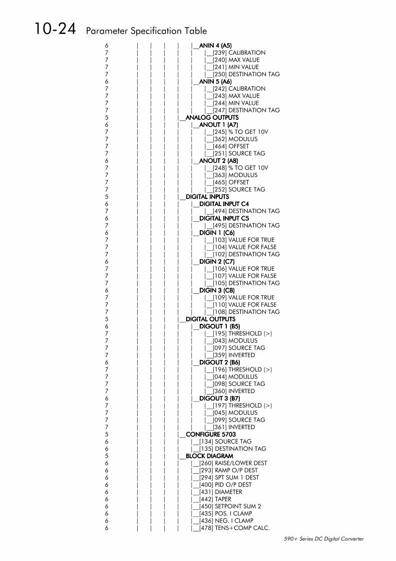
10-24 Parameter Specification Table
590+ Series DC Digital Converter
6 | | | | |__ANIN 4 (A5)ANIN 4 (A5)ANIN 4 (A5)ANIN 4 (A5)7 | | | | | |__[239] CALIBRATION7 | | | | | |__[240] MAX VALUE7 | | | | | |__[241] MIN VALUE7 | | | | | |__[250] DESTINATION TAG6 | | | | |__ANIN 5 (A6)ANIN 5 (A6)ANIN 5 (A6)ANIN 5 (A6)7 | | | | | |__[242] CALIBRATION7 | | | | | |__[243] MAX VALUE7 | | | | | |__[244] MIN VALUE7 | | | | | |__[247] DESTINATION TAG5 | | | |__ANALOG OUTPUTSANALOG OUTPUTSANALOG OUTPUTSANALOG OUTPUTS6 | | | | |__ANOUT 1 (A7)ANOUT 1 (A7)ANOUT 1 (A7)ANOUT 1 (A7)7 | | | | | |__[245] % TO GET 10V7 | | | | | |__[362] MODULUS7 | | | | | |__[464] OFFSET7 | | | | | |__[251] SOURCE TAG6 | | | | |__ANOUT 2 (A8)ANOUT 2 (A8)ANOUT 2 (A8)ANOUT 2 (A8)7 | | | | | |__[248] % TO GET 10V7 | | | | | |__[363] MODULUS7 | | | | | |__[465] OFFSET7 | | | | | |__[252] SOURCE TAG5 | | | |__DIGITAL INPUTSDIGITAL INPUTSDIGITAL INPUTSDIGITAL INPUTS6 | | | | |__DIGITAL INPUT C4DIGITAL INPUT C4DIGITAL INPUT C4DIGITAL INPUT C47 | | | | | |__[494] DESTINATION TAG6 | | | | |__DIGITAL INPUT C5DIGITAL INPUT C5DIGITAL INPUT C5DIGITAL INPUT C57 | | | | | |__[495] DESTINATION TAG6 | | | | |__DIGIN 1 (C6)DIGIN 1 (C6)DIGIN 1 (C6)DIGIN 1 (C6)7 | | | | | |__[103] VALUE FOR TRUE7 | | | | | |__[104] VALUE FOR FALSE7 | | | | | |__[102] DESTINATION TAG6 | | | | |__DIGIN 2 (C7)DIGIN 2 (C7)DIGIN 2 (C7)DIGIN 2 (C7)7 | | | | | |__[106] VALUE FOR TRUE7 | | | | | |__[107] VALUE FOR FALSE7 | | | | | |__[105] DESTINATION TAG6 | | | | |__DIGIN 3 (C8)DIGIN 3 (C8)DIGIN 3 (C8)DIGIN 3 (C8)7 | | | | | |__[109] VALUE FOR TRUE7 | | | | | |__[110] VALUE FOR FALSE7 | | | | | |__[108] DESTINATION TAG5 | | | |__DIGITAL OUTPUTSDIGITAL OUTPUTSDIGITAL OUTPUTSDIGITAL OUTPUTS6 | | | | |__DIGOUT 1 (B5)DIGOUT 1 (B5)DIGOUT 1 (B5)DIGOUT 1 (B5)7 | | | | | |__[195] THRESHOLD (>)7 | | | | | |__[043] MODULUS7 | | | | | |__[097] SOURCE TAG7 | | | | | |__[359] INVERTED6 | | | | |__DIGOUT 2 (B6)DIGOUT 2 (B6)DIGOUT 2 (B6)DIGOUT 2 (B6)7 | | | | | |__[196] THRESHOLD (>)7 | | | | | |__[044] MODULUS7 | | | | | |__[098] SOURCE TAG7 | | | | | |__[360] INVERTED6 | | | | |__DIGOUT 3 (B7)DIGOUT 3 (B7)DIGOUT 3 (B7)DIGOUT 3 (B7)7 | | | | | |__[197] THRESHOLD (>)7 | | | | | |__[045] MODULUS7 | | | | | |__[099] SOURCE TAG7 | | | | | |__[361] INVERTED5 | | | |__CONFIGURE 5703CONFIGURE 5703CONFIGURE 5703CONFIGURE 57036 | | | | |__[134] SOURCE TAG6 | | | | |__[135] DESTINATION TAG5 | | | |__BLOCK DIAGRAMBLOCK DIAGRAMBLOCK DIAGRAMBLOCK DIAGRAM6 | | | | |__[260] RAISE/LOWER DEST6 | | | | |__[293] RAMP O/P DEST6 | | | | |__[294] SPT SUM 1 DEST6 | | | | |__[400] PID O/P DEST6 | | | | |__[431] DIAMETER6 | | | | |__[442] TAPER6 | | | | |__[450] SETPOINT SUM 26 | | | | |__[435] POS. I CLAMP6 | | | | |__[436] NEG. I CLAMP6 | | | | |__[478] TENS+COMP CALC.
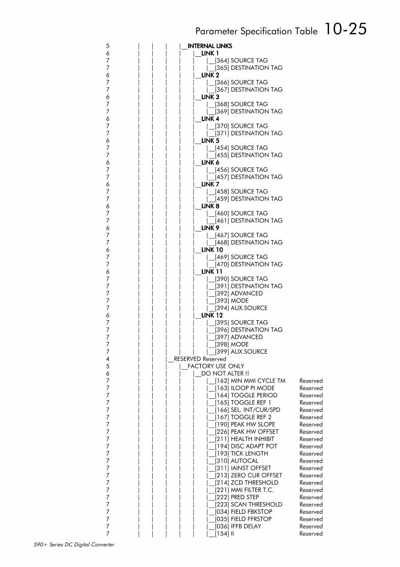
Parameter Specification Table 10-25
590+ Series DC Digital Converter
5 | | | |__INTERNAL LINKSINTERNAL LINKSINTERNAL LINKSINTERNAL LINKS6 | | | | |__LINK 1LINK 1LINK 1LINK 17 | | | | | |__[364] SOURCE TAG7 | | | | | |__[365] DESTINATION TAG6 | | | | |__LINK 2LINK 2LINK 2LINK 27 | | | | | |__[366] SOURCE TAG7 | | | | | |__[367] DESTINATION TAG6 | | | | |__LINK 3LINK 3LINK 3LINK 37 | | | | | |__[368] SOURCE TAG7 | | | | | |__[369] DESTINATION TAG6 | | | | |__LINK 4LINK 4LINK 4LINK 47 | | | | | |__[370] SOURCE TAG7 | | | | | |__[371] DESTINATION TAG6 | | | | |__LINK 5LINK 5LINK 5LINK 57 | | | | | |__[454] SOURCE TAG7 | | | | | |__[455] DESTINATION TAG6 | | | | |__LINK 6LINK 6LINK 6LINK 67 | | | | | |__[456] SOURCE TAG7 | | | | | |__[457] DESTINATION TAG6 | | | | |__LINK 7LINK 7LINK 7LINK 77 | | | | | |__[458] SOURCE TAG7 | | | | | |__[459] DESTINATION TAG6 | | | | |__LINK 8LINK 8LINK 8LINK 87 | | | | | |__[460] SOURCE TAG7 | | | | | |__[461] DESTINATION TAG6 | | | | |__LINK 9LINK 9LINK 9LINK 97 | | | | | |__[467] SOURCE TAG7 | | | | | |__[468] DESTINATION TAG6 | | | | |__LINK 10LINK 10LINK 10LINK 107 | | | | | |__[469] SOURCE TAG7 | | | | | |__[470] DESTINATION TAG6 | | | | |__LINK 11LINK 11LINK 11LINK 117 | | | | | |__[390] SOURCE TAG7 | | | | | |__[391] DESTINATION TAG7 | | | | | |__[392] ADVANCED7 | | | | | |__[393] MODE7 | | | | | |__[394] AUX.SOURCE6 | | | | |__LINK 12LINK 12LINK 12LINK 127 | | | | | |__[395] SOURCE TAG7 | | | | | |__[396] DESTINATION TAG7 | | | | | |__[397] ADVANCED7 | | | | | |__[398] MODE7 | | | | | |__[399] AUX.SOURCE4 | | |__RESERVED Reserved5 | | | |__FACTORY USE ONLY6 | | | | |__DO NOT ALTER !!7 | | | | | |__[162] MIN MMI CYCLE TM Reserved7 | | | | | |__[163] ILOOP PI MODE Reserved7 | | | | | |__[164] TOGGLE PERIOD Reserved7 | | | | | |__[165] TOGGLE REF 1 Reserved7 | | | | | |__[166] SEL. INT/CUR/SPD Reserved7 | | | | | |__[167] TOGGLE REF 2 Reserved7 | | | | | |__[190] PEAK HW SLOPE Reserved7 | | | | | |__[226] PEAK HW OFFSET Reserved7 | | | | | |__[211] HEALTH INHIBIT Reserved7 | | | | | |__[194] DISC ADAPT POT Reserved7 | | | | | |__[193] TICK LENGTH Reserved7 | | | | | |__[310] AUTOCAL Reserved7 | | | | | |__[311] IAINST OFFSET Reserved7 | | | | | |__[213] ZERO CUR OFFSET Reserved7 | | | | | |__[214] ZCD THRESHOLD Reserved7 | | | | | |__[221] MMI FILTER T.C. Reserved7 | | | | | |__[222] PRED STEP Reserved7 | | | | | |__[223] SCAN THRESHOLD Reserved7 | | | | | |__[034] FIELD FBKSTOP Reserved7 | | | | | |__[035] FIELD FFRSTOP Reserved7 | | | | | |__[036] IFFB DELAY Reserved7 | | | | | |__[154] II Reserved
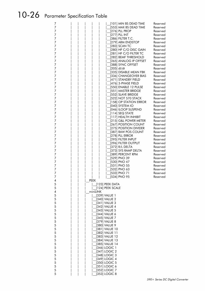
10-26 Parameter Specification Table
590+ Series DC Digital Converter
7 | | | | | |__[101] MIN BS DEAD TIME Reserved7 | | | | | |__[553] MAX BS DEAD TIME Reserved7 | | | | | |__[276] PLL PROP Reserved7 | | | | | |__[277] PLL INT Reserved7 | | | | | |__[386] FILTER T.C. Reserved7 | | | | | |__[279] ARM ENDSTOP Reserved7 | | | | | |__[283] SCAN TC Reserved7 | | | | | |__[280] HF C/O DISC GAIN Reserved7 | | | | | |__[281] HF C/O FILTER TC Reserved7 | | | | | |__[282] BEMF THRESHOLD Reserved7 | | | | | |__[265] ANALOG IP OFFSET Reserved7 | | | | | |__[388] SYNC OFFSET Reserved7 | | | | | |__[205] dI/dt Reserved7 | | | | | |__[335] DISABLE MEAN FBK Reserved7 | | | | | |__[336] CHANGEOVER BIAS Reserved7 | | | | | |__[471] STANDBY FIELD Reserved7 | | | | | |__[476] 3-PHASE FIELD Reserved7 | | | | | |__[550] ENABLE 12 PULSE Reserved7 | | | | | |__[551] MASTER BRIDGE Reserved7 | | | | | |__[552] SLAVE BRIDGE Reserved7 | | | | | |__[522] NOT 570 STACK Reserved7 | | | | | |__[158] OP STATION ERROR Reserved7 | | | | | |__[040] SYSTEM IO Reserved7 | | | | | |__[046] ILOOP SUSPEND Reserved7 | | | | | |__[114] SEQ STATE Reserved7 | | | | | |__[117] HEALTH INHIBIT Reserved7 | | | | | |__[215] G&L POWER METER Reserved7 | | | | | |__[267] POSITION COUNT Reserved7 | | | | | |__[275] POSITION DIVIDER Reserved7 | | | | | |__[387] RAW POS COUNT Reserved7 | | | | | |__[278] PLL ERROR Reserved7 | | | | | |__[295] FILTER INPUT Reserved7 | | | | | |__[296] FILTER OUTPUT Reserved7 | | | | | |__[372] R/L DELTA Reserved7 | | | | | |__[373] SYS RAMP DELTA Reserved7 | | | | | |__[389] PERCENT RPM Reserved7 | | | | | |__[529] PNO 39 Reserved7 | | | | | |__[530] PNO 47 Reserved7 | | | | | |__[531] PNO 55 Reserved7 | | | | | |__[532] PNO 63 Reserved7 | | | | | |__[533] PNO 71 Reserved7 | | | | | |__[534] PNO 95 Reserved4 | | |__PEEK5 | | | |__[123] PEEK DATA5 | | | |__[124] PEEK SCALE4 | | |__miniLINK5 | | | |__[339] VALUE 15 | | | |__[340] VALUE 25 | | | |__[341] VALUE 35 | | | |__[342] VALUE 45 | | | |__[343] VALUE 55 | | | |__[344] VALUE 65 | | | |__[345] VALUE 75 | | | |__[379] VALUE 85 | | | |__[380] VALUE 95 | | | |__[381] VALUE 105 | | | |__[382] VALUE 115 | | | |__[383] VALUE 125 | | | |__[384] VALUE 135 | | | |__[385] VALUE 145 | | | |__[346] LOGIC 15 | | | |__[347] LOGIC 25 | | | |__[348] LOGIC 35 | | | |__[349] LOGIC 45 | | | |__[350] LOGIC 55 | | | |__[351] LOGIC 65 | | | |__[352] LOGIC 75 | | | |__[353] LOGIC 8

Parameter Specification Table 10-27
590+ Series DC Digital Converter
3 | |__CONFIGURE DRIVECONFIGURE DRIVECONFIGURE DRIVECONFIGURE DRIVE4 | | |__[039] CONFIGURE ENABLE4 | | |__[521] NOM MOTOR VOLTS4 | | |__[523] ARMATURE CURRENT4 | | |__[524] FIELD CURRENT4 | | |__[543] ZERO CAL INPUTS Reserved4 | | |__[209] FLD.CTRL MODE4 | | |__[210] FLD.VOLTS RATIO4 | | |__[018] AUTOTUNE4 | | |__[047] SPEED FBK SELECT4 | | |__[024] ENCODER LINES4 | | |__[022] ENCODER RPM4 | | |__[049] ENCODER SIGN4 | | |__[013] SPD.INT.TIME4 | | |__[014] SPD.PROP.GAIN

10-28 Parameter Specification Table
590+ Series DC Digital Converter
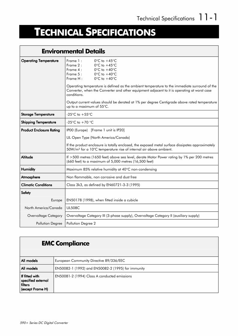
Technical Specifications 11-1
590+ Series DC Digital Converter
11 TECHNICAL SPECIFICATIONS
Environmental DetailsOperating TemperatureOperating TemperatureOperating TemperatureOperating Temperature Frame 1 : 0°C to +45°C
Frame 2 : 0°C to +45°CFrame 4 : 0°C to +40°CFrame 5 : 0°C to +40°CFrame H : 0°C to +40°C
Operating temperature is defined as the ambient temperature to the immediate surround of theConverter, when the Converter and other equipment adjacent to it is operating at worst caseconditions.
Output current values should be derated at 1% per degree Centigrade above rated temperatureup to a maximum of 55°C.
Storage TemperatureStorage TemperatureStorage TemperatureStorage Temperature -25°C to +55°C
Shipping TemperatureShipping TemperatureShipping TemperatureShipping Temperature -25°C to +70 °C
Product Enclosure RatingProduct Enclosure RatingProduct Enclosure RatingProduct Enclosure Rating IP00 (Europe) [Frame 1 unit is IP20]
UL Open Type (North America/Canada)
If the product enclosure is totally enclosed, the exposed metal surface dissipates approximately50W/m² for a 10°C temperature rise of internal air above ambient.
AltitudeAltitudeAltitudeAltitude If >500 metres (1650 feet) above sea level, derate Motor Power rating by 1% per 200 metres(660 feet) to a maximum of 5,000 metres (16,500 feet)
HumidityHumidityHumidityHumidity Maximum 85% relative humidity at 40°C non-condensing
AtmosphereAtmosphereAtmosphereAtmosphere Non flammable, non corrosive and dust free
Climatic ConditionsClimatic ConditionsClimatic ConditionsClimatic Conditions Class 3k3, as defined by EN60721-3-3 (1995)
SafetySafetySafetySafety
Europe EN50178 (1998), when fitted inside a cubicle
North America/Canada UL508C
Overvoltage Category Overvoltage Category III (3-phase supply), Overvoltage Category II (auxiliary supply)
Pollution Degree Pollution Degree 2
EMC Compliance
All modelsAll modelsAll modelsAll models European Community Directive 89/336/EEC
All modelsAll modelsAll modelsAll models EN50082-1 (1992) and EN50082-2 (1995) for immunity
If fitted withIf fitted withIf fitted withIf fitted withspecified externalspecified externalspecified externalspecified externalfiltersfiltersfiltersfilters(except Frame H)(except Frame H)(except Frame H)(except Frame H)
EN50081-2 (1994) Class A conducted emissions
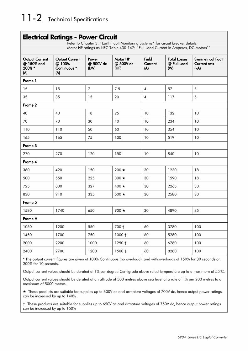
11-2 Technical Specifications
590+ Series DC Digital Converter
Electrical Ratings - Power CircuitRefer to Chapter 3: “ Earth Fault Monitoring Systems” for circuit breaker details.Motor HP ratings as NEC Table 430-147: “ Full Load Current in Amperes, DC Motors” ’
Output CurrentOutput CurrentOutput CurrentOutput Current@ 150% and@ 150% and@ 150% and@ 150% and200% *200% *200% *200% *(A)(A)(A)(A)
Output CurrentOutput CurrentOutput CurrentOutput Current@ 100%@ 100%@ 100%@ 100%Continuous *Continuous *Continuous *Continuous *(A)(A)(A)(A)
PowerPowerPowerPower@ 500V dc@ 500V dc@ 500V dc@ 500V dc(kW)(kW)(kW)(kW)
Motor HPMotor HPMotor HPMotor HP@ 500V dc@ 500V dc@ 500V dc@ 500V dc(HP)(HP)(HP)(HP)
FieldFieldFieldFieldCurrentCurrentCurrentCurrent(A)(A)(A)(A)
Total LossesTotal LossesTotal LossesTotal Losses@ Full Load@ Full Load@ Full Load@ Full Load(W)(W)(W)(W)
Symmetrical FaultSymmetrical FaultSymmetrical FaultSymmetrical FaultCurrent rmsCurrent rmsCurrent rmsCurrent rms(kA)(kA)(kA)(kA)
Frame 1Frame 1Frame 1Frame 1
15 15 7 7.5 4 57 5
35 35 15 20 4 117 5
Frame 2Frame 2Frame 2Frame 2
40 40 18 25 10 132 10
70 70 30 40 10 234 10
110 110 50 60 10 354 10
165 165 75 100 10 519 10
Frame 3Frame 3Frame 3Frame 3
270 270 120 150 10 840 10
Frame 4Frame 4Frame 4Frame 4
380 420 150 200 30 1230 18
500 550 225 300 30 1590 18
725 800 327 400 30 2265 30
830 910 335 500 30 2580 30
Frame 5Frame 5Frame 5Frame 5
1580 1740 650 900 30 4890 85
Frame HFrame HFrame HFrame H
1050 1200 550 700 † 60 3780 100
1450 1700 750 1000 † 60 5280 100
2000 2200 1000 1250 † 60 6780 100
2400 2700 1200 1500 † 60 8280 100
* The output current figures are given at 100% Continuous (no overload), and with overloads of 150% for 30 seconds or200% for 10 seconds.
Output current values should be derated at 1% per degree Centigrade above rated temperature up to a maximum of 55°C.
Output current values should be derated at an altitude of 500 metres above sea level at a rate of 1% per 200 metres to amaximum of 5000 metres.
These products are suitable for supplies up to 600V ac and armature voltages of 700V dc, hence output power ratingscan be increased by up to 140%
† These products are suitable for supplies up to 690V ac and armature voltages of 750V dc, hence output power ratingscan be increased by up to 150%
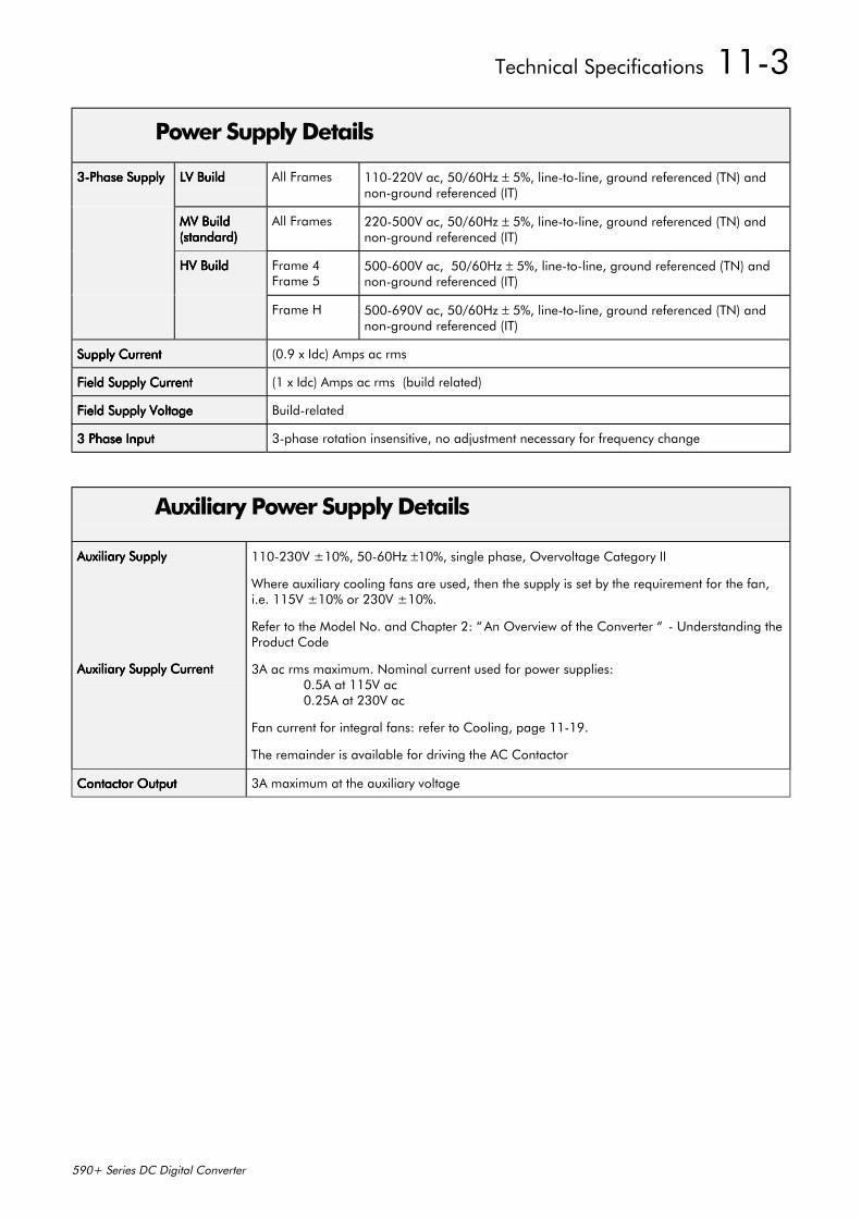
Technical Specifications 11-3
590+ Series DC Digital Converter
Power Supply Details
3-Phase Supply3-Phase Supply3-Phase Supply3-Phase Supply LV BuildLV BuildLV BuildLV Build All Frames 110-220V ac, 50/60Hz ± 5%, line-to-line, ground referenced (TN) andnon-ground referenced (IT)
MV BuildMV BuildMV BuildMV Build(standard)(standard)(standard)(standard)
All Frames 220-500V ac, 50/60Hz ± 5%, line-to-line, ground referenced (TN) andnon-ground referenced (IT)
HV BuildHV BuildHV BuildHV Build Frame 4Frame 5
500-600V ac, 50/60Hz ± 5%, line-to-line, ground referenced (TN) andnon-ground referenced (IT)
Frame H 500-690V ac, 50/60Hz ± 5%, line-to-line, ground referenced (TN) andnon-ground referenced (IT)
Supply CurrentSupply CurrentSupply CurrentSupply Current (0.9 x Idc) Amps ac rms
Field Supply CurrentField Supply CurrentField Supply CurrentField Supply Current (1 x Idc) Amps ac rms (build related)
Field Supply VoltageField Supply VoltageField Supply VoltageField Supply Voltage Build-related
3 Phase Input3 Phase Input3 Phase Input3 Phase Input 3-phase rotation insensitive, no adjustment necessary for frequency change
Auxiliary Power Supply Details
Auxiliary SupplyAuxiliary SupplyAuxiliary SupplyAuxiliary Supply
Auxiliary Supply CurrentAuxiliary Supply CurrentAuxiliary Supply CurrentAuxiliary Supply Current
110-230V ±10%, 50-60Hz ±10%, single phase, Overvoltage Category II
Where auxiliary cooling fans are used, then the supply is set by the requirement for the fan,i.e. 115V ±10% or 230V ±10%.
Refer to the Model No. and Chapter 2: “ An Overview of the Converter “ - Understanding theProduct Code
3A ac rms maximum. Nominal current used for power supplies:0.5A at 115V ac0.25A at 230V ac
Fan current for integral fans: refer to Cooling, page 11-19.
The remainder is available for driving the AC Contactor
Contactor OutputContactor OutputContactor OutputContactor Output 3A maximum at the auxiliary voltage
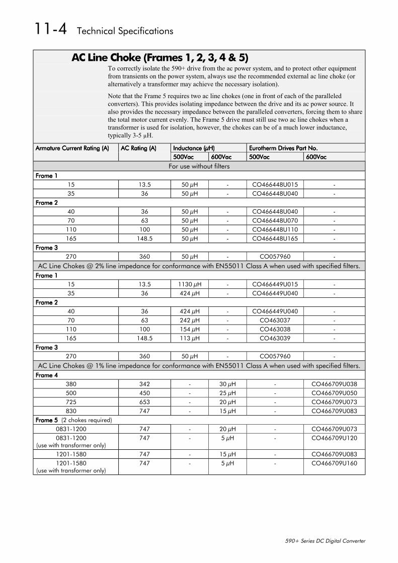
11-4 Technical Specifications
590+ Series DC Digital Converter
AC Line Choke (Frames 1, 2, 3, 4 & 5)To correctly isolate the 590+ drive from the ac power system, and to protect other equipmentfrom transients on the power system, always use the recommended external ac line choke (oralternatively a transformer may achieve the necessary isolation).
Note that the Frame 5 requires two ac line chokes (one in front of each of the paralleledconverters). This provides isolating impedance between the drive and its ac power source. Italso provides the necessary impedance between the paralleled converters, forcing them to sharethe total motor current evenly. The Frame 5 drive must still use two ac line chokes when atransformer is used for isolation, however, the chokes can be of a much lower inductance,typically 3-5 µH.
Armature Current Rating (A)Armature Current Rating (A)Armature Current Rating (A)Armature Current Rating (A) AC Rating (A)AC Rating (A)AC Rating (A)AC Rating (A) Inductance (µH)Inductance (µH)Inductance (µH)Inductance (µH) Eurotherm Drives Part No.Eurotherm Drives Part No.Eurotherm Drives Part No.Eurotherm Drives Part No.500Vac500Vac500Vac500Vac 600Vac600Vac600Vac600Vac 500Vac500Vac500Vac500Vac 600Vac600Vac600Vac600Vac
For use without filtersFrame 1Frame 1Frame 1Frame 1
15 13.5 50 µH - CO466448U015 -35 36 50 µH - CO466448U040 -
Frame 2Frame 2Frame 2Frame 240 36 50 µH - CO466448U040 -70 63 50 µH - CO466448U070 -110 100 50 µH - CO466448U110 -165 148.5 50 µH - CO466448U165 -
Frame 3Frame 3Frame 3Frame 3270 360 50 µH - CO057960 -
AC Line Chokes @ 2% line impedance for conformance with EN55011 Class A when used with specified filters.Frame 1Frame 1Frame 1Frame 1
15 13.5 1130 µH - CO466449U015 -35 36 424 µH - CO466449U040 -
Frame 2Frame 2Frame 2Frame 240 36 424 µH - CO466449U040 -70 63 242 µH - CO463037 -110 100 154 µH - CO463038 -165 148.5 113 µH - CO463039 -
Frame 3Frame 3Frame 3Frame 3270 360 50 µH - CO057960 -
AC Line Chokes @ 1% line impedance for conformance with EN55011 Class A when used with specified filters.Frame 4Frame 4Frame 4Frame 4
380 342 - 30 µH - CO466709U038500 450 - 25 µH - CO466709U050725 653 - 20 µH - CO466709U073830 747 - 15 µH - CO466709U083
Frame 5 Frame 5 Frame 5 Frame 5 (2 chokes required)0831-1200 747 - 20 µH - CO466709U0730831-1200
(use with transformer only)747 - 5 µH - CO466709U120
1201-1580 747 - 15 µH - CO466709U0831201-1580
(use with transformer only)747 - 5 µH - CO466709U160
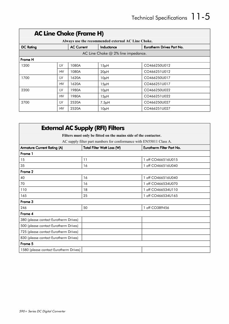
Technical Specifications 11-5
590+ Series DC Digital Converter
AC Line Choke (Frame H)Always use the recommended external AC Line Choke.
DC RatingDC RatingDC RatingDC Rating AC CurrentAC CurrentAC CurrentAC Current InductanceInductanceInductanceInductance Eurotherm Drives Part No.Eurotherm Drives Part No.Eurotherm Drives Part No.Eurotherm Drives Part No.
AC Line Choke @ 2% line impedance.
Frame HFrame HFrame HFrame H
1200 LV 1080A 15µH CO466250U012
HV 1080A 20µH CO466251U012
1700 LV 1620A 10µH CO466250U017
HV 1620A 15µH CO466251U017
2200 LV 1980A 10µH CO466250U022
HV 1980A 15µH CO466251U022
2700 LV 2520A 7.5µH CO466250U027
HV 2520A 10µH CO466251U027
External AC Supply (RFI) FiltersFilters must only be fitted on the mains side of the contactor.AC supply filter part numbers for conformance with EN55011 Class A.
Armature Current Rating (A)Armature Current Rating (A)Armature Current Rating (A)Armature Current Rating (A) Total Filter Watt Loss (W)Total Filter Watt Loss (W)Total Filter Watt Loss (W)Total Filter Watt Loss (W) Eurotherm Filter Part No.Eurotherm Filter Part No.Eurotherm Filter Part No.Eurotherm Filter Part No.
Frame 1Frame 1Frame 1Frame 1
15 11 1 off CO466516U015
35 16 1 off CO466516U040
Frame 2Frame 2Frame 2Frame 2
40 16 1 off CO466516U040
70 16 1 off CO466534U070
110 18 1 off CO466534U110
165 25 1 off CO466534U165
Frame 3Frame 3Frame 3Frame 3
246 50 1 off CO389456
Frame 4Frame 4Frame 4Frame 4
380 (please contact Eurotherm Drives)
500 (please contact Eurotherm Drives)
725 (please contact Eurotherm Drives)
830 (please contact Eurotherm Drives)
Frame 5Frame 5Frame 5Frame 5
1580 (please contact Eurotherm Drives)
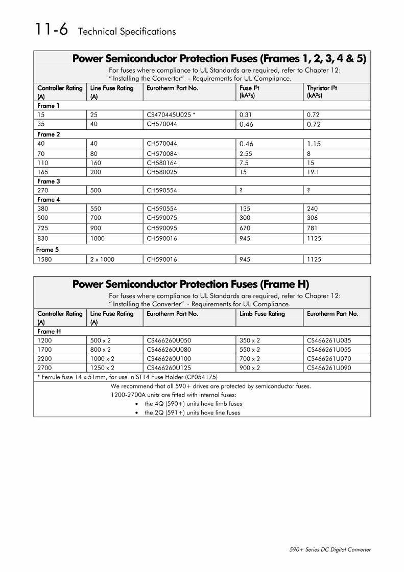
11-6 Technical Specifications
590+ Series DC Digital Converter
Power Semiconductor Protection Fuses (Frames 1, 2, 3, 4 & 5)For fuses where compliance to UL Standards are required, refer to Chapter 12:“ Installing the Converter” – Requirements for UL Compliance.
Controller RatingController RatingController RatingController Rating(A)(A)(A)(A)
Line Fuse RatingLine Fuse RatingLine Fuse RatingLine Fuse Rating(A)(A)(A)(A)
Eurotherm Part No.Eurotherm Part No.Eurotherm Part No.Eurotherm Part No. Fuse I²tFuse I²tFuse I²tFuse I²t(kA²s)(kA²s)(kA²s)(kA²s)
Thyristor I²tThyristor I²tThyristor I²tThyristor I²t(kA²s)(kA²s)(kA²s)(kA²s)
Frame 1Frame 1Frame 1Frame 115 25 CS470445U025 * 0.31 0.7235 40 CH570044 0.46 0.72Frame 2Frame 2Frame 2Frame 240 40 CH570044 0.46 1.1570 80 CH570084 2.55 8110 160 CH580164 7.5 15165 200 CH580025 15 19.1Frame 3Frame 3Frame 3Frame 3270 500 CH590554 ? ?Frame 4Frame 4Frame 4Frame 4380 550 CH590554 135 240500 700 CH590075 300 306
725 900 CH590095 670 781
830 1000 CH590016 945 1125
Frame 5Frame 5Frame 5Frame 5
1580 2 x 1000 CH590016 945 1125
Power Semiconductor Protection Fuses (Frame H)For fuses where compliance to UL Standards are required, refer to Chapter 12:“ Installing the Converter” - Requirements for UL Compliance.
Controller RatingController RatingController RatingController Rating(A)(A)(A)(A)
Line Fuse RatingLine Fuse RatingLine Fuse RatingLine Fuse Rating(A)(A)(A)(A)
Eurotherm Part No.Eurotherm Part No.Eurotherm Part No.Eurotherm Part No. Limb Fuse RatingLimb Fuse RatingLimb Fuse RatingLimb Fuse Rating Eurotherm Part No.Eurotherm Part No.Eurotherm Part No.Eurotherm Part No.
Frame HFrame HFrame HFrame H1200 500 x 2 CS466260U050 350 x 2 CS466261U0351700 800 x 2 CS466260U080 550 x 2 CS466261U0552200 1000 x 2 CS466260U100 700 x 2 CS466261U0702700 1250 x 2 CS466260U125 900 x 2 CS466261U090* Ferrule fuse 14 x 51mm, for use in ST14 Fuse Holder (CP054175)
We recommend that all 590+ drives are protected by semiconductor fuses.1200-2700A units are fitted with internal fuses:
• the 4Q (590+) units have limb fuses• the 2Q (591+) units have line fuses
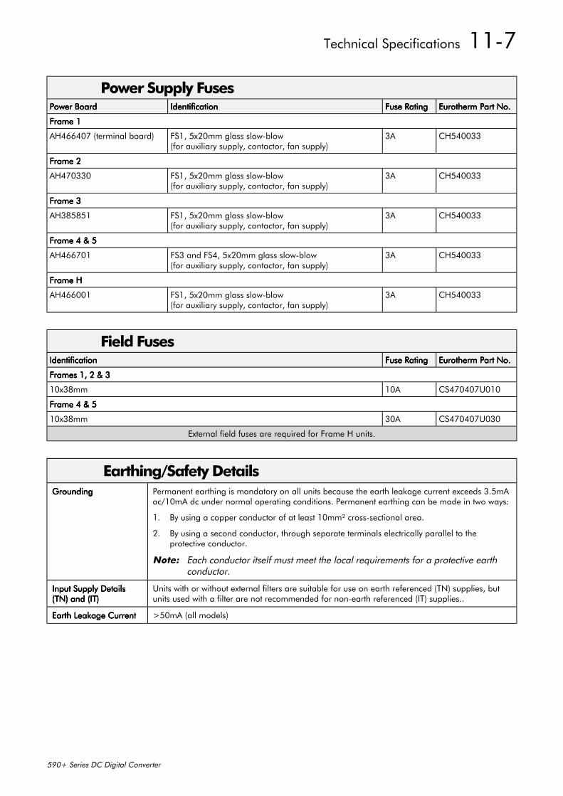
Technical Specifications 11-7
590+ Series DC Digital Converter
Power Supply FusesPower BoardPower BoardPower BoardPower Board IdentificationIdentificationIdentificationIdentification Fuse RatingFuse RatingFuse RatingFuse Rating Eurotherm Part No.Eurotherm Part No.Eurotherm Part No.Eurotherm Part No.
Frame 1Frame 1Frame 1Frame 1
AH466407 (terminal board) FS1, 5x20mm glass slow-blow(for auxiliary supply, contactor, fan supply)
3A CH540033
Frame 2Frame 2Frame 2Frame 2
AH470330 FS1, 5x20mm glass slow-blow(for auxiliary supply, contactor, fan supply)
3A CH540033
Frame 3Frame 3Frame 3Frame 3
AH385851 FS1, 5x20mm glass slow-blow(for auxiliary supply, contactor, fan supply)
3A CH540033
Frame 4 & 5Frame 4 & 5Frame 4 & 5Frame 4 & 5
AH466701 FS3 and FS4, 5x20mm glass slow-blow(for auxiliary supply, contactor, fan supply)
3A CH540033
Frame HFrame HFrame HFrame H
AH466001 FS1, 5x20mm glass slow-blow(for auxiliary supply, contactor, fan supply)
3A CH540033
Field FusesIdentificationIdentificationIdentificationIdentification Fuse RatingFuse RatingFuse RatingFuse Rating Eurotherm Part No.Eurotherm Part No.Eurotherm Part No.Eurotherm Part No.
Frames 1, 2 & 3Frames 1, 2 & 3Frames 1, 2 & 3Frames 1, 2 & 3
10x38mm 10A CS470407U010
Frame 4 & 5Frame 4 & 5Frame 4 & 5Frame 4 & 5
10x38mm 30A CS470407U030
External field fuses are required for Frame H units.
Earthing/Safety DetailsGroundingGroundingGroundingGrounding Permanent earthing is mandatory on all units because the earth leakage current exceeds 3.5mA
ac/10mA dc under normal operating conditions. Permanent earthing can be made in two ways:
1. By using a copper conductor of at least 10mm² cross-sectional area.
2. By using a second conductor, through separate terminals electrically parallel to theprotective conductor.
Note: Each conductor itself must meet the local requirements for a protective earthconductor.
Input Supply DetailsInput Supply DetailsInput Supply DetailsInput Supply Details(TN) and (IT)(TN) and (IT)(TN) and (IT)(TN) and (IT)
Units with or without external filters are suitable for use on earth referenced (TN) supplies, butunits used with a filter are not recommended for non-earth referenced (IT) supplies..
Earth Leakage CurrentEarth Leakage CurrentEarth Leakage CurrentEarth Leakage Current >50mA (all models)
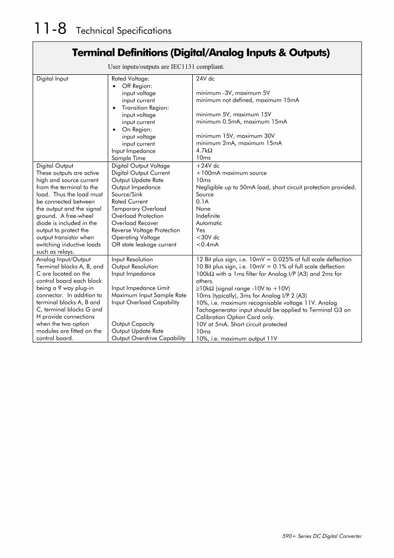
11-8 Technical Specifications
590+ Series DC Digital Converter
Terminal Definitions (Digital/Analog Inputs & Outputs)User inputs/outputs are IEC1131 compliant.
Digital Input Rated Voltage:• Off Region:
input voltageinput current
• Transition Region:input voltageinput current
• On Region:input voltageinput current
Input ImpedanceSample Time
24V dc
minimum -3V, maximum 5Vminimum not defined, maximum 15mA
minimum 5V, maximum 15Vminimum 0.5mA, maximum 15mA
minimum 15V, maximum 30Vminimum 2mA, maximum 15mA4.7kΩ10ms
Digital OutputThese outputs are activehigh and source currentfrom the terminal to theload. Thus the load mustbe connected betweenthe output and the signalground. A free-wheeldiode is included in theoutput to protect theoutput transistor whenswitching inductive loadssuch as relays.
Digital Output VoltageDigital Output CurrentOutput Update RateOutput ImpedanceSource/SinkRated CurrentTemporary OverloadOverload ProtectionOverload RecoverReverse Voltage ProtectionOperating VoltageOff state leakage current
+24V dc+100mA maximum source10msNegligible up to 50mA load, short circuit protection provided.Source0.1ANoneIndefiniteAutomaticYes<30V dc<0.4mA
Analog Input/OutputTerminal blocks A, B, andC are located on thecontrol board each blockbeing a 9 way plug-inconnector. In addition toterminal blocks A, B andC, terminal blocks G andH provide connectionswhen the two optionmodules are fitted on thecontrol board.
Input ResolutionOutput ResolutionInput Impedance
Input Impedance LimitMaximum Input Sample RateInput Overload Capability
Output CapacityOutput Update RateOutput Overdrive Capability
12 Bit plus sign, i.e. 10mV = 0.025% of full scale deflection10 Bit plus sign, i.e. 10mV = 0.1% of full scale deflection100kΩ with a 1ms filter for Analog I/P (A3) and 2ms forothers.≥10kΩ (signal range -10V to +10V)10ms (typically), 3ms for Analog I/P 2 (A3)10%, i.e. maximum recognisable voltage 11V. AnalogTachogenerator input should be applied to Terminal G3 onCalibration Option Card only.10V at 5mA. Short circuit protected10ms10%, i.e. maximum output 11V
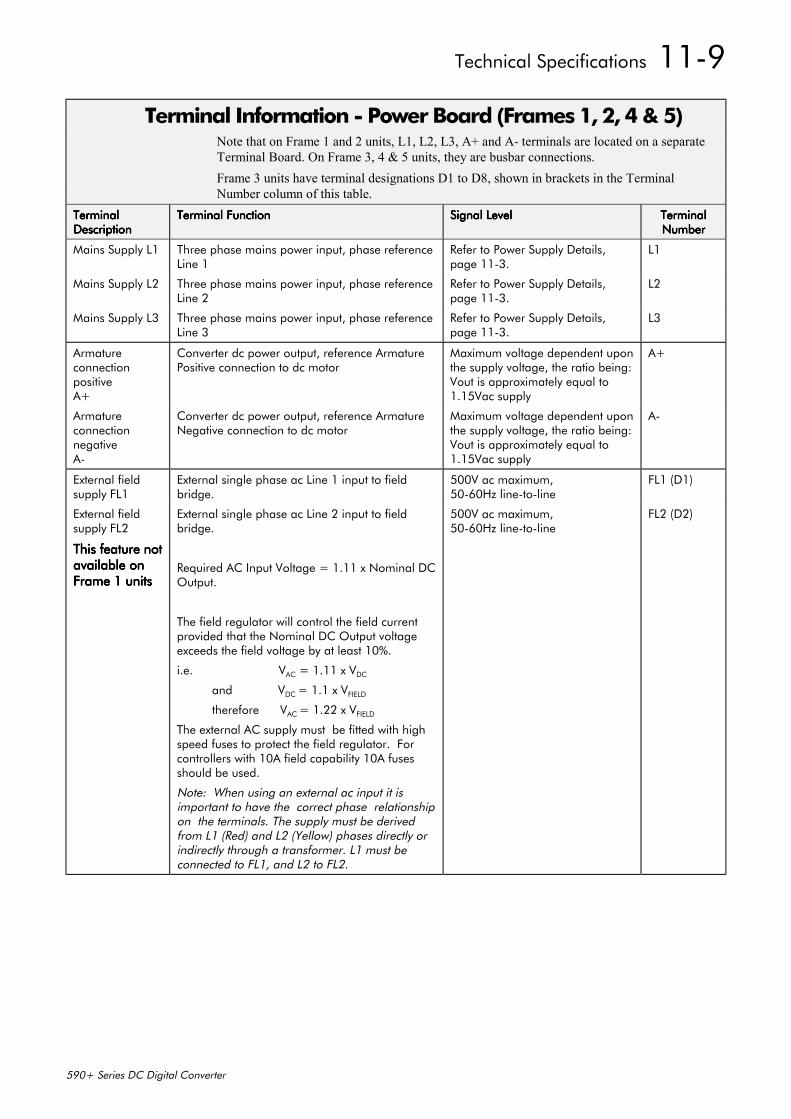
Technical Specifications 11-9
590+ Series DC Digital Converter
Terminal Information - Power Board (Frames 1, 2, 4 & 5)Note that on Frame 1 and 2 units, L1, L2, L3, A+ and A- terminals are located on a separateTerminal Board. On Frame 3, 4 & 5 units, they are busbar connections.Frame 3 units have terminal designations D1 to D8, shown in brackets in the TerminalNumber column of this table.
TerminalTerminalTerminalTerminalDescriptionDescriptionDescriptionDescription
Terminal FunctionTerminal FunctionTerminal FunctionTerminal Function Signal LevelSignal LevelSignal LevelSignal Level TerminalTerminalTerminalTerminalNumberNumberNumberNumber
Mains Supply L1 Three phase mains power input, phase referenceLine 1
Refer to Power Supply Details,page 11-3.
L1
Mains Supply L2 Three phase mains power input, phase referenceLine 2
Refer to Power Supply Details,page 11-3.
L2
Mains Supply L3 Three phase mains power input, phase referenceLine 3
Refer to Power Supply Details,page 11-3.
L3
ArmatureconnectionpositiveA+
Converter dc power output, reference ArmaturePositive connection to dc motor
Maximum voltage dependent uponthe supply voltage, the ratio being:Vout is approximately equal to1.15Vac supply
A+
ArmatureconnectionnegativeA-
Converter dc power output, reference ArmatureNegative connection to dc motor
Maximum voltage dependent uponthe supply voltage, the ratio being:Vout is approximately equal to1.15Vac supply
A-
External fieldsupply FL1
External single phase ac Line 1 input to fieldbridge.
500V ac maximum,50-60Hz line-to-line
FL1 (D1)
External fieldsupply FL2
This feature notThis feature notThis feature notThis feature notavailable onavailable onavailable onavailable onFrame 1 unitsFrame 1 unitsFrame 1 unitsFrame 1 units
External single phase ac Line 2 input to fieldbridge.
Required AC Input Voltage = 1.11 x Nominal DCOutput.
The field regulator will control the field currentprovided that the Nominal DC Output voltageexceeds the field voltage by at least 10%.
i.e. VAC = 1.11 x VDC
and VDC = 1.1 x VFIELD
therefore VAC = 1.22 x VFIELD
The external AC supply must be fitted with highspeed fuses to protect the field regulator. Forcontrollers with 10A field capability 10A fusesshould be used.
Note: When using an external ac input it isimportant to have the correct phase relationshipon the terminals. The supply must be derivedfrom L1 (Red) and L2 (Yellow) phases directly orindirectly through a transformer. L1 must beconnected to FL1, and L2 to FL2.
500V ac maximum,50-60Hz line-to-line
FL2 (D2)
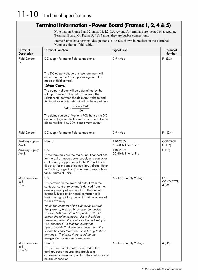
11-10 Technical Specifications
590+ Series DC Digital Converter
Terminal Information - Power Board (Frames 1, 2, 4 & 5)Note that on Frame 1 and 2 units, L1, L2, L3, A+ and A- terminals are located on a separateTerminal Board. On Frame 3, 4 & 5 units, they are busbar connections.Frame 3 units have terminal designations D1 to D8, shown in brackets in the TerminalNumber column of this table.
TerminalTerminalTerminalTerminalDescriptionDescriptionDescriptionDescription
Terminal FunctionTerminal FunctionTerminal FunctionTerminal Function Signal LevelSignal LevelSignal LevelSignal Level TerminalTerminalTerminalTerminalNumberNumberNumberNumber
Field OutputF-
DC supply for motor field connections.
The DC output voltage at these terminals willdepend upon the AC supply voltage and themode of field control.
Voltage ControlVoltage ControlVoltage ControlVoltage Control
The output voltage will be determined by theratio parameter in the field variables. Therelationship between the dc output voltage andAC input voltage is determined by the equation:-
Vdc Vratio x VAC100
=
The default value of Vratio is 90% hence the DCoutput voltage will be the same as for a full wavediode rectifier i.e., 90% is maximum output.
0.9 x Vac F– (D3)
Field OutputF+
DC supply for motor field connections. 0.9 x Vac F+ (D4)
Auxiliary supplyAux N
Neutral 110-230V50-60Hz line-to-line
CONTROLN (D7)
Auxiliary supplyAux L
Line
These terminals are the mains input connectionsfor the switch mode power supply and contactorcontrol relay supply. Refer to the Product Code(Block 8) for the specified auxiliary voltage. Referto Cooling, page 11-19 when using separate acfans, (Frame H units).
110-230V50-60Hz line-to-line
L (D8)
Main contactorcoilCon L
Line
This terminal is the switched output from thecontactor control relay and is derived from theauxiliary supply at terminal D8. The output isinternally fused at 3A hence contactor coilshaving a high pick-up current must be operatedvia a slave relay.
Note: The contacts of the Contactor ControlRelay are suppressed by a series connectedresistor (680 Ohms) and capacitor (22nF) toprotect the relay contacts. Users should beaware that when the contactor Control Relay is“De-energised”, a leakage current ofapproximately 2mA can be expected and thisshould be considered when interfacing to theseterminals. Typically, there could be theenergisation of very sensitive relays.
Auxiliary Supply Voltage EXTCONTACTOR3 (D5)
Main contactorcoilCon N
Neutral
This terminal is internally connected to theauxiliary supply neutral and provides aconvenient connection point for the contactor coilneutral connection.
Auxiliary Supply Voltage 4 (D6)
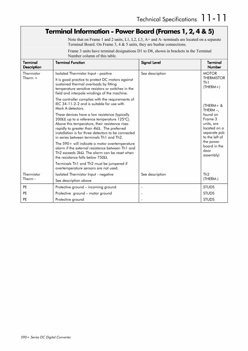
Technical Specifications 11-11
590+ Series DC Digital Converter
Terminal Information - Power Board (Frames 1, 2, 4 & 5)Note that on Frame 1 and 2 units, L1, L2, L3, A+ and A- terminals are located on a separateTerminal Board. On Frame 3, 4 & 5 units, they are busbar connections.Frame 3 units have terminal designations D1 to D8, shown in brackets in the TerminalNumber column of this table.
TerminalTerminalTerminalTerminalDescriptionDescriptionDescriptionDescription
Terminal FunctionTerminal FunctionTerminal FunctionTerminal Function Signal LevelSignal LevelSignal LevelSignal Level TerminalTerminalTerminalTerminalNumberNumberNumberNumber
ThermistorTherm +
Isolated Thermistor Input - positive
It is good practice to protect DC motors againstsustained thermal overloads by fittingtemperature sensitive resistors or switches in thefield and interpole windings of the machine.
The controller complies with the requirements ofIEC 34-11-2-2 and is suitable for use withMark A detectors.
These devices have a low resistance (typically200Ω) up to a reference temperature 125oC).Above this temperature, their resistance risesrapidly to greater than 4kΩ. The preferredinstallation is for three detectors to be connectedin series between terminals Th1 and Th2.
The 590+ will indicate a motor overtemperaturealarm if the external resistance between Th1 andTh2 exceeds 3kΩ. The alarm can be reset whenthe resistance falls below 750Ω.
Terminals Th1 and Th2 must be jumpered ifovertemperature sensors are not used.
See description MOTORTHERMISTORTh1(THERM+)
(THERM+ &THERM –,found onFrame 3units, arelocated on aseparate pcbto the left ofthe powerboard in thedoorassembly)
ThermistorTherm -
Isolated Thermistor Input - negative
See description above
See description Th2(THERM-)
PE Protective ground – incoming ground - STUDS
PE Protective ground – motor ground - STUDS
PE Protective ground - STUDS
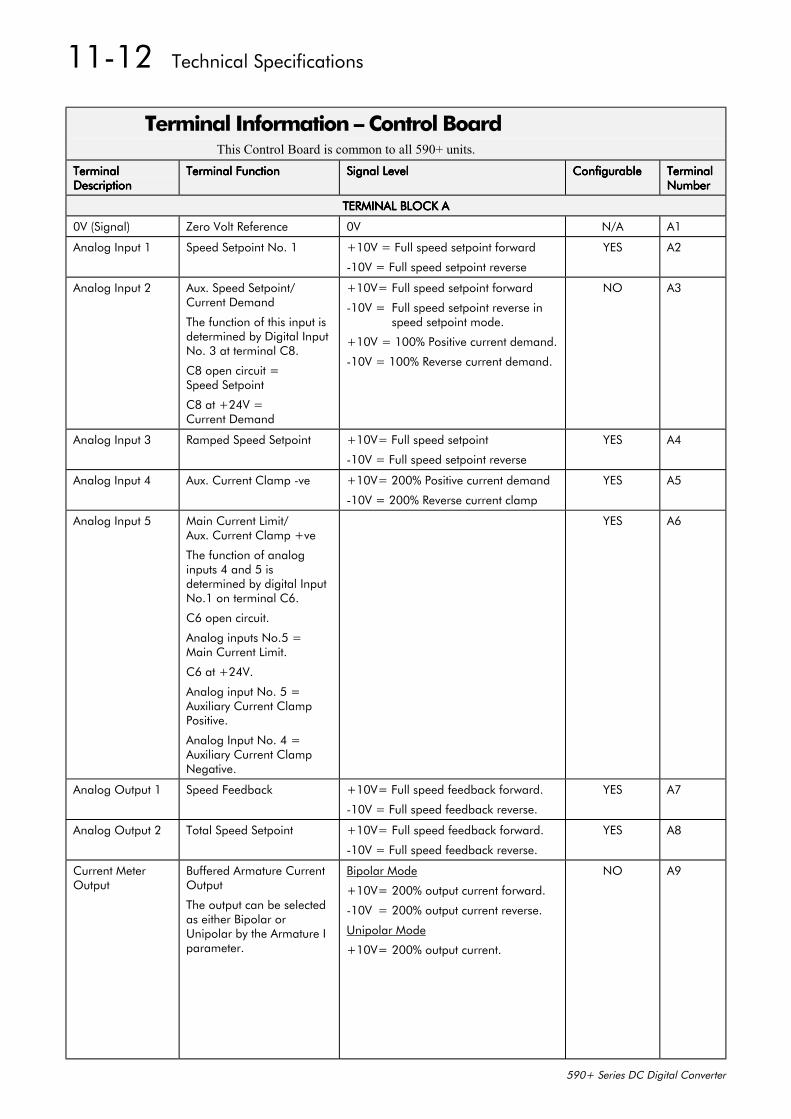
11-12 Technical Specifications
590+ Series DC Digital Converter
Terminal Information – Control BoardThis Control Board is common to all 590+ units.
TerminalTerminalTerminalTerminalDescriptionDescriptionDescriptionDescription
Terminal FunctionTerminal FunctionTerminal FunctionTerminal Function Signal LevelSignal LevelSignal LevelSignal Level ConfigurableConfigurableConfigurableConfigurable TerminalTerminalTerminalTerminalNumberNumberNumberNumber
TERMINAL BLOCK ATERMINAL BLOCK ATERMINAL BLOCK ATERMINAL BLOCK A
0V (Signal) Zero Volt Reference 0V N/A A1
Analog Input 1 Speed Setpoint No. 1 +10V = Full speed setpoint forward
-10V = Full speed setpoint reverse
YES A2
Analog Input 2 Aux. Speed Setpoint/Current Demand
The function of this input isdetermined by Digital InputNo. 3 at terminal C8.
C8 open circuit =Speed Setpoint
C8 at +24V =Current Demand
+10V= Full speed setpoint forward
-10V = Full speed setpoint reverse in speed setpoint mode.
+10V = 100% Positive current demand.
-10V = 100% Reverse current demand.
NO A3
Analog Input 3 Ramped Speed Setpoint +10V= Full speed setpoint
-10V = Full speed setpoint reverse
YES A4
Analog Input 4 Aux. Current Clamp -ve +10V= 200% Positive current demand
-10V = 200% Reverse current clamp
YES A5
Analog Input 5 Main Current Limit/Aux. Current Clamp +ve
The function of analoginputs 4 and 5 isdetermined by digital InputNo.1 on terminal C6.
C6 open circuit.
Analog inputs No.5 =Main Current Limit.
C6 at +24V.
Analog input No. 5 =Auxiliary Current ClampPositive.
Analog Input No. 4 =Auxiliary Current ClampNegative.
YES A6
Analog Output 1 Speed Feedback +10V= Full speed feedback forward.
-10V = Full speed feedback reverse.
YES A7
Analog Output 2 Total Speed Setpoint +10V= Full speed feedback forward.
-10V = Full speed feedback reverse.
YES A8
Current MeterOutput
Buffered Armature CurrentOutput
The output can be selectedas either Bipolar orUnipolar by the Armature Iparameter.
Bipolar Mode
+10V= 200% output current forward.
-10V = 200% output current reverse.
Unipolar Mode
+10V= 200% output current.
NO A9
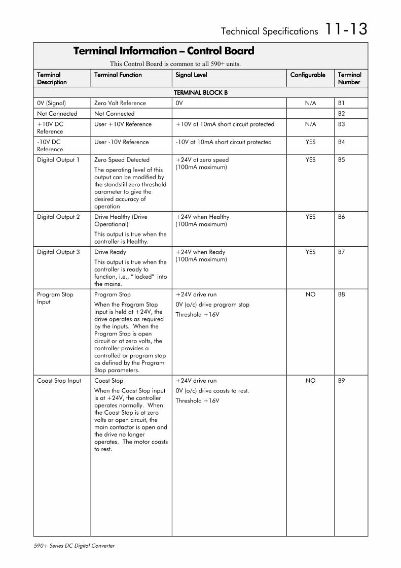
Technical Specifications 11-13
590+ Series DC Digital Converter
Terminal Information – Control BoardThis Control Board is common to all 590+ units.
TerminalTerminalTerminalTerminalDescriptionDescriptionDescriptionDescription
Terminal FunctionTerminal FunctionTerminal FunctionTerminal Function Signal LevelSignal LevelSignal LevelSignal Level ConfigurableConfigurableConfigurableConfigurable TerminalTerminalTerminalTerminalNumberNumberNumberNumber
TERMINAL BLOCK BTERMINAL BLOCK BTERMINAL BLOCK BTERMINAL BLOCK B
0V (Signal) Zero Volt Reference 0V N/A B1
Not Connected Not Connected B2
+10V DCReference
User +10V Reference +10V at 10mA short circuit protected N/A B3
-10V DCReference
User -10V Reference -10V at 10mA short circuit protected YES B4
Digital Output 1 Zero Speed Detected
The operating level of thisoutput can be modified bythe standstill zero thresholdparameter to give thedesired accuracy ofoperation
+24V at zero speed(100mA maximum)
YES B5
Digital Output 2 Drive Healthy (DriveOperational)
This output is true when thecontroller is Healthy.
+24V when Healthy(100mA maximum)
YES B6
Digital Output 3 Drive Ready
This output is true when thecontroller is ready tofunction, i.e., “ locked” intothe mains.
+24V when Ready(100mA maximum)
YES B7
Program StopInput
Program Stop
When the Program Stopinput is held at +24V, thedrive operates as requiredby the inputs. When theProgram Stop is opencircuit or at zero volts, thecontroller provides acontrolled or program stopas defined by the ProgramStop parameters.
+24V drive run
0V (o/c) drive program stop
Threshold +16V
NO B8
Coast Stop Input Coast Stop
When the Coast Stop inputis at +24V, the controlleroperates normally. Whenthe Coast Stop is at zerovolts or open circuit, themain contactor is open andthe drive no longeroperates. The motor coaststo rest.
+24V drive run
0V (o/c) drive coasts to rest.
Threshold +16V
NO B9
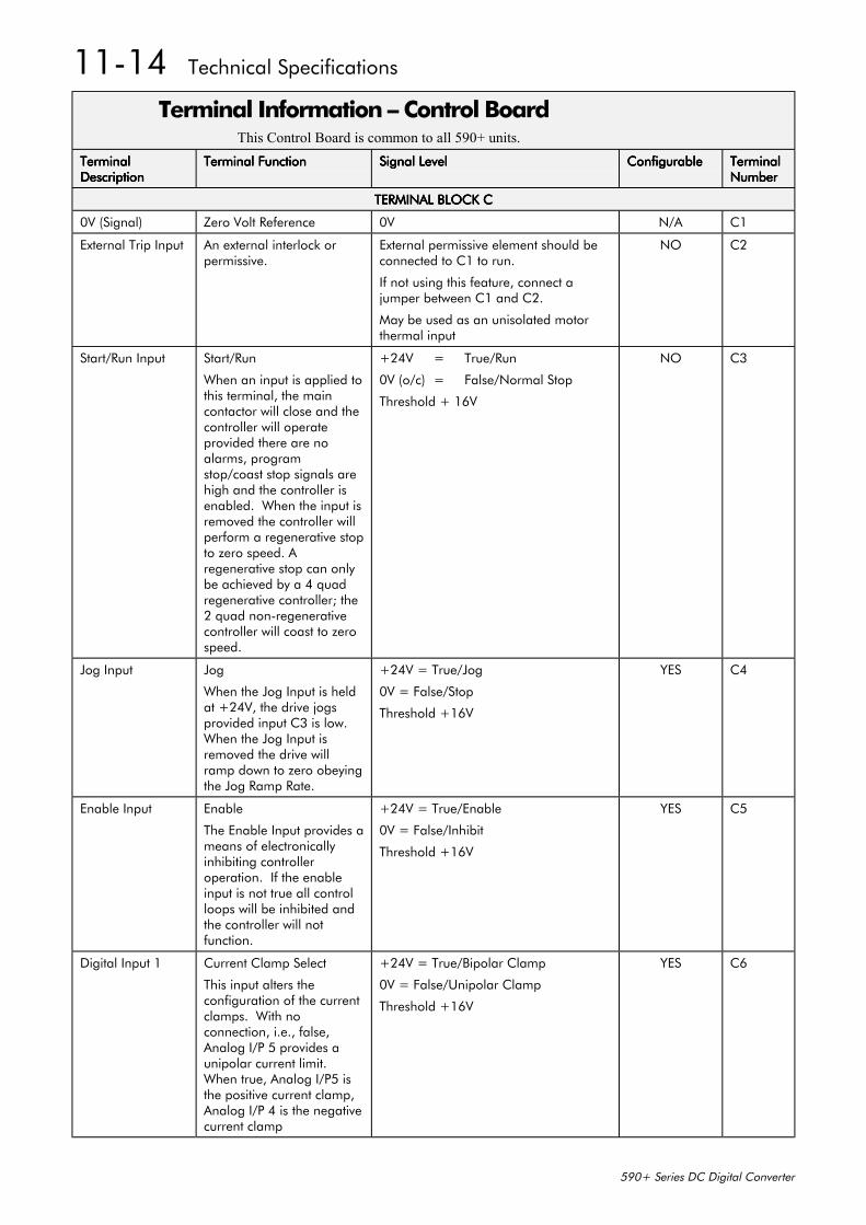
11-14 Technical Specifications
590+ Series DC Digital Converter
Terminal Information – Control BoardThis Control Board is common to all 590+ units.
TerminalTerminalTerminalTerminalDescriptionDescriptionDescriptionDescription
Terminal FunctionTerminal FunctionTerminal FunctionTerminal Function Signal LevelSignal LevelSignal LevelSignal Level ConfigurableConfigurableConfigurableConfigurable TerminalTerminalTerminalTerminalNumberNumberNumberNumber
TERMINAL BLOCK CTERMINAL BLOCK CTERMINAL BLOCK CTERMINAL BLOCK C
0V (Signal) Zero Volt Reference 0V N/A C1
External Trip Input An external interlock orpermissive.
External permissive element should beconnected to C1 to run.
If not using this feature, connect ajumper between C1 and C2.
May be used as an unisolated motorthermal input
NO C2
Start/Run Input Start/Run
When an input is applied tothis terminal, the maincontactor will close and thecontroller will operateprovided there are noalarms, programstop/coast stop signals arehigh and the controller isenabled. When the input isremoved the controller willperform a regenerative stopto zero speed. Aregenerative stop can onlybe achieved by a 4 quadregenerative controller; the2 quad non-regenerativecontroller will coast to zerospeed.
+24V = True/Run
0V (o/c) = False/Normal Stop
Threshold + 16V
NO C3
Jog Input Jog
When the Jog Input is heldat +24V, the drive jogsprovided input C3 is low.When the Jog Input isremoved the drive willramp down to zero obeyingthe Jog Ramp Rate.
+24V = True/Jog
0V = False/Stop
Threshold +16V
YES C4
Enable Input Enable
The Enable Input provides ameans of electronicallyinhibiting controlleroperation. If the enableinput is not true all controlloops will be inhibited andthe controller will notfunction.
+24V = True/Enable
0V = False/Inhibit
Threshold +16V
YES C5
Digital Input 1 Current Clamp Select
This input alters theconfiguration of the currentclamps. With noconnection, i.e., false,Analog I/P 5 provides aunipolar current limit.When true, Analog I/P5 isthe positive current clamp,Analog I/P 4 is the negativecurrent clamp
+24V = True/Bipolar Clamp
0V = False/Unipolar Clamp
Threshold +16V
YES C6
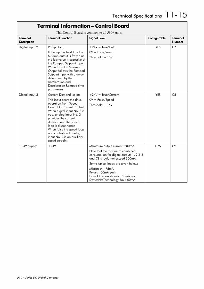
Technical Specifications 11-15
590+ Series DC Digital Converter
Terminal Information – Control BoardThis Control Board is common to all 590+ units.
TerminalTerminalTerminalTerminalDescriptionDescriptionDescriptionDescription
Terminal FunctionTerminal FunctionTerminal FunctionTerminal Function Signal LevelSignal LevelSignal LevelSignal Level ConfigurableConfigurableConfigurableConfigurable TerminalTerminalTerminalTerminalNumberNumberNumberNumber
Digital Input 2 Ramp Hold
If the input is held true theS-Ramp output is frozen atthe last value irrespective ofthe Ramped Setpoint Input.When false the S-RampOutput follows the RampedSetpoint Input with a delaydetermined by theAcceleration andDeceleration Ramped timeparameters.
+24V = True/Hold
0V = False/Ramp
Threshold + 16V
YES C7
Digital Input 3 Current Demand Isolate
This input alters the driveoperation from SpeedControl to Current Control.When digital input No. 3 istrue, analog input No. 2provides the currentdemand and the speedloop is disconnected.When false the speed loopis in control and analoginput No. 2 is an auxiliaryspeed setpoint.
+24V = True/Current
0V = False/Speed
Threshold + 16V
YES C8
+24V Supply +24V Maximum output current: 200mA
Note that the maximum combinedconsumption for digital outputs 1, 2 & 3and C9 should not exceed 300mA.
Some typical loads are given below:
Microtach : 75mARelays : 50mA eachFiber Optic ancillaries : 50mA eachDeviceNetTechnology Box : 50mA
N/A C9
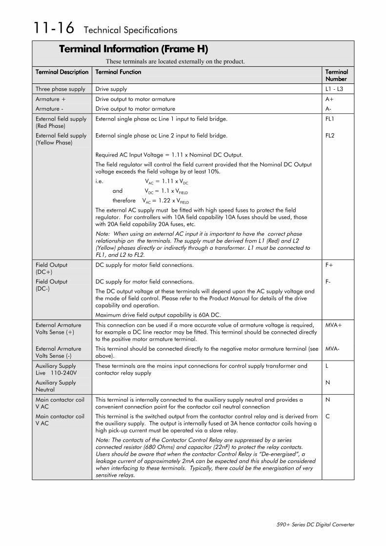
11-16 Technical Specifications
590+ Series DC Digital Converter
Terminal Information (Frame H)These terminals are located externally on the product.
Terminal DescriptionTerminal DescriptionTerminal DescriptionTerminal Description Terminal FunctionTerminal FunctionTerminal FunctionTerminal Function TerminalTerminalTerminalTerminalNumberNumberNumberNumber
Three phase supply Drive supply L1 - L3
Armature + Drive output to motor armature A+
Armature - Drive output to motor armature A-
External field supply(Red Phase)
External field supply(Yellow Phase)
External single phase ac Line 1 input to field bridge.
External single phase ac Line 2 input to field bridge.
Required AC Input Voltage = 1.11 x Nominal DC Output.
The field regulator will control the field current provided that the Nominal DC Outputvoltage exceeds the field voltage by at least 10%.
i.e. VAC = 1.11 x VDC
and VDC = 1.1 x VFIELD
therefore VAC = 1.22 x VFIELD
The external AC supply must be fitted with high speed fuses to protect the fieldregulator. For controllers with 10A field capability 10A fuses should be used, thosewith 20A field capability 20A fuses, etc.
Note: When using an external AC input it is important to have the correct phaserelationship on the terminals. The supply must be derived from L1 (Red) and L2(Yellow) phases directly or indirectly through a transformer. L1 must be connected toFL1, and L2 to FL2.
FL1
FL2
Field Output(DC+)
Field Output(DC-)
DC supply for motor field connections.
DC supply for motor field connections.
The DC output voltage at these terminals will depend upon the AC supply voltage andthe mode of field control. Please refer to the Product Manual for details of the drivecapability and operation.
Maximum drive field output capability is 60A DC.
F+
F-
External ArmatureVolts Sense (+)
This connection can be used if a more accurate value of armature voltage is required,for example a DC line reactor may be fitted. This terminal should be connected directlyto the positive motor armature terminal.
MVA+
External ArmatureVolts Sense (-)
This terminal should be connected directly to the negative motor armature terminal (seeabove).
MVA-
Auxiliary SupplyLive 110-240V
Auxiliary SupplyNeutral
These terminals are the mains input connections for control supply transformer andcontactor relay supply
L
N
Main contactor coilV AC
This terminal is internally connected to the auxiliary supply neutral and provides aconvenient connection point for the contactor coil neutral connection
N
Main contactor coilV AC
This terminal is the switched output from the contactor control relay and is derived fromthe auxiliary supply. The output is internally fused at 3A hence contactor coils having ahigh pick-up current must be operated via a slave relay.
Note: The contacts of the Contactor Control Relay are suppressed by a seriesconnected resistor (680 Ohms) and capacitor (22nF) to protect the relay contacts.Users should be aware that when the contactor Control Relay is “De-energised”, aleakage current of approximately 2mA can be expected and this should be consideredwhen interfacing to these terminals. Typically, there could be the energisation of verysensitive relays.
C
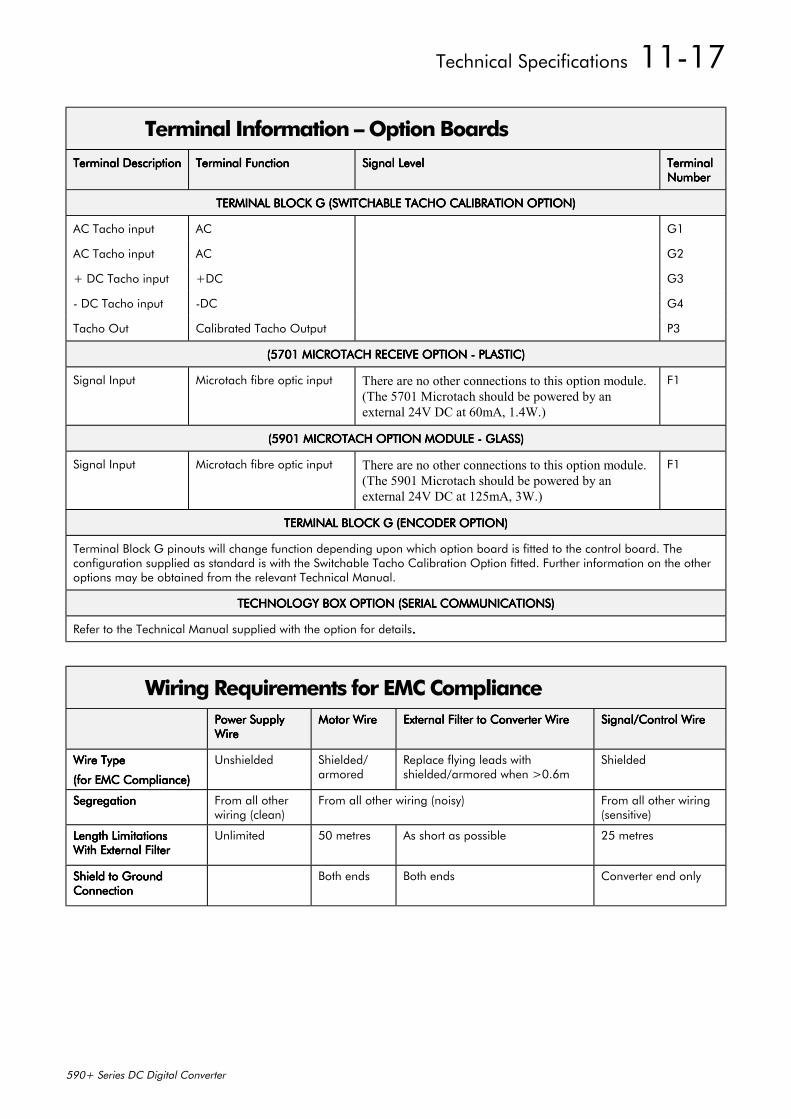
Technical Specifications 11-17
590+ Series DC Digital Converter
Terminal Information – Option BoardsTerminal DescriptionTerminal DescriptionTerminal DescriptionTerminal Description Terminal FunctionTerminal FunctionTerminal FunctionTerminal Function Signal LevelSignal LevelSignal LevelSignal Level TerminalTerminalTerminalTerminal
NumberNumberNumberNumber
TERMINAL BLOCK G (SWITCHABLE TACHO CALIBRATION OPTION)TERMINAL BLOCK G (SWITCHABLE TACHO CALIBRATION OPTION)TERMINAL BLOCK G (SWITCHABLE TACHO CALIBRATION OPTION)TERMINAL BLOCK G (SWITCHABLE TACHO CALIBRATION OPTION)
AC Tacho input AC G1
AC Tacho input AC G2
+ DC Tacho input +DC G3
- DC Tacho input -DC G4
Tacho Out Calibrated Tacho Output P3
(5701 MICROTACH RECEIVE OPTION - PLASTIC)(5701 MICROTACH RECEIVE OPTION - PLASTIC)(5701 MICROTACH RECEIVE OPTION - PLASTIC)(5701 MICROTACH RECEIVE OPTION - PLASTIC)
Signal Input Microtach fibre optic input There are no other connections to this option module.(The 5701 Microtach should be powered by anexternal 24V DC at 60mA, 1.4W.)
F1
(5901 MICROTACH OPTION MODULE - GLASS)(5901 MICROTACH OPTION MODULE - GLASS)(5901 MICROTACH OPTION MODULE - GLASS)(5901 MICROTACH OPTION MODULE - GLASS)
Signal Input Microtach fibre optic input There are no other connections to this option module.(The 5901 Microtach should be powered by anexternal 24V DC at 125mA, 3W.)
F1
TERMINAL BLOCK G (ENCODER OPTION)TERMINAL BLOCK G (ENCODER OPTION)TERMINAL BLOCK G (ENCODER OPTION)TERMINAL BLOCK G (ENCODER OPTION)
Terminal Block G pinouts will change function depending upon which option board is fitted to the control board. Theconfiguration supplied as standard is with the Switchable Tacho Calibration Option fitted. Further information on the otheroptions may be obtained from the relevant Technical Manual.
TECHNOLOGY BOX OPTION (SERIAL COMMUNICATIONS)TECHNOLOGY BOX OPTION (SERIAL COMMUNICATIONS)TECHNOLOGY BOX OPTION (SERIAL COMMUNICATIONS)TECHNOLOGY BOX OPTION (SERIAL COMMUNICATIONS)
Refer to the Technical Manual supplied with the option for details....
Wiring Requirements for EMC CompliancePower SupplyPower SupplyPower SupplyPower SupplyWireWireWireWire
Motor WireMotor WireMotor WireMotor Wire External Filter to Converter WireExternal Filter to Converter WireExternal Filter to Converter WireExternal Filter to Converter Wire Signal/Control WireSignal/Control WireSignal/Control WireSignal/Control Wire
Wire TypeWire TypeWire TypeWire Type
(for EMC Compliance)(for EMC Compliance)(for EMC Compliance)(for EMC Compliance)
Unshielded Shielded/armored
Replace flying leads withshielded/armored when >0.6m
Shielded
SegregationSegregationSegregationSegregation From all otherwiring (clean)
From all other wiring (noisy) From all other wiring(sensitive)
Length LimitationsLength LimitationsLength LimitationsLength LimitationsWith External FilterWith External FilterWith External FilterWith External Filter
Unlimited 50 metres As short as possible 25 metres
Shield to GroundShield to GroundShield to GroundShield to GroundConnectionConnectionConnectionConnection
Both ends Both ends Converter end only
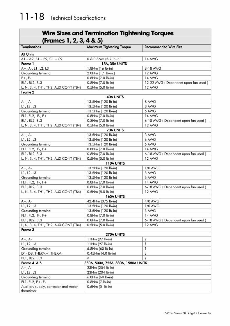
11-18 Technical Specifications
590+ Series DC Digital Converter
Wire Sizes and Termination Tightening Torques(Frames 1, 2, 3, 4 & 5)
TerminationsTerminationsTerminationsTerminations Maximum Tightening TorqueMaximum Tightening TorqueMaximum Tightening TorqueMaximum Tightening Torque Recommended Wire SizeRecommended Wire SizeRecommended Wire SizeRecommended Wire Size
All UnitsAll UnitsAll UnitsAll UnitsA1 – A9, B1 – B9, C1 – C9 0.6-0.8Nm (5-7 lb-in.) 14 AWGFrame 1 15A, 35A UNITSFrame 1 15A, 35A UNITSFrame 1 15A, 35A UNITSFrame 1 15A, 35A UNITSA+, A-, L1, L2, L3 1.8Nm (16 lb-in) 8-18 AWGGrounding terminal 2.0Nm (17 lb-in.) 12 AWGF+, F- 0.8Nm (7.0 lb-in) 14 AWGBL1, BL2, BL3 0.8Nm (7.0 lb-in) 12-22 AWG ( Dependent upon fan used )L, N, 3, 4, TH1, TH2, AUX CONT (TB4) 0.5Nm (5.0 lb-in) 12 AWGFrame 2Frame 2Frame 2Frame 2
40A UNITS40A UNITS40A UNITS40A UNITSA+, A- 13.5Nm (120 lb-in) 8 AWGL1, L2, L3 13.5Nm (120 lb-in) 8 AWGGrounding terminal 13.5Nm (120 lb-in) 6 AWGFL1, FL2, F-, F+ 0.8Nm (7.0 lb-in) 14 AWGBL1, BL2, BL3 0.8Nm (7.0 lb-in) 6-18 AWG ( Dependent upon fan used )L, N, 3, 4, TH1, TH2, AUX CONT (TB4) 0.5Nm (5.0 lb-in) 12 AWG
70A UNITS70A UNITS70A UNITS70A UNITSA+, A- 13.5Nm (120 lb-in) 3 AWGL1, L2, L3 13.5Nm (120 lb-in) 6 AWGGrounding terminal 13.5Nm (120 lb-in) 6 AWGFL1, FL2, F-, F+ 0.8Nm (7.0 lb-in) 14 AWGBL1, BL2, BL3 0.8Nm (7.0 lb-in) 6-18 AWG ( Dependent upon fan used )L, N, 3, 4, TH1, TH2, AUX CONT (TB4) 0.5Nm (5.0 lb-in) 12 AWG
110A UNITS110A UNITS110A UNITS110A UNITSA+, A- 13.5Nm (120 lb-in) 1/0 AWGL1, L2, L3 13.5Nm (120 lb-in) 3 AWGGrounding terminal 13.5Nm (120 lb-in) 6 AWGFL1, FL2, F-, F+ 0.8Nm (7.0 lb-in) 14 AWGBL1, BL2, BL3 0.8Nm (7.0 lb-in) 6-18 AWG ( Dependent upon fan used )L, N, 3, 4, TH1, TH2, AUX CONT (TB4) 0.5Nm (5.0 lb-in) 12 AWG
165A UNITS165A UNITS165A UNITS165A UNITSA+, A- 42.4Nm (375 lb-in) 4/0 AWGL1, L2, L3 13.5Nm (120 lb-in) 1/0 AWGGrounding terminal 13.5Nm (120 lb-in) 3 AWGFL1, FL2, F-, F+ 0.8Nm (7.0 lb-in) 14 AWGBL1, BL2, BL3 0.8Nm (7.0 lb-in) 6-18 AWG ( Dependent upon fan used )L, N, 3, 4, TH1, TH2, AUX CONT (TB4) 0.5Nm (5.0 lb-in) 12 AWGFrame 3Frame 3Frame 3Frame 3
270A UNITS270A UNITS270A UNITS270A UNITSA+, A- 11Nm (97 lb-in) ?L1, L2, L3 11Nm (97 lb-in) ?Grounding terminal 6.8Nm (60 lb-in) ?D1- D8, THERM+, THERM- 0.45Nm (4.0 lb-in) ?BL1, BL2, BL3 ? ?Frame 4 & 5 380A, 500A, 725A, 830A, 1580A UNITSFrame 4 & 5 380A, 500A, 725A, 830A, 1580A UNITSFrame 4 & 5 380A, 500A, 725A, 830A, 1580A UNITSFrame 4 & 5 380A, 500A, 725A, 830A, 1580A UNITSA+, A- 23Nm (204 lb-in)L1, L2, L3 23Nm (204 lb-in)Grounding terminal 6.8Nm (60 lb-in)FL1, FL2, F+, F- 0.8Nm (7 lb-in)Auxiliary supply, contactor and motorthermistor
0.6Nm (5 lb-in)
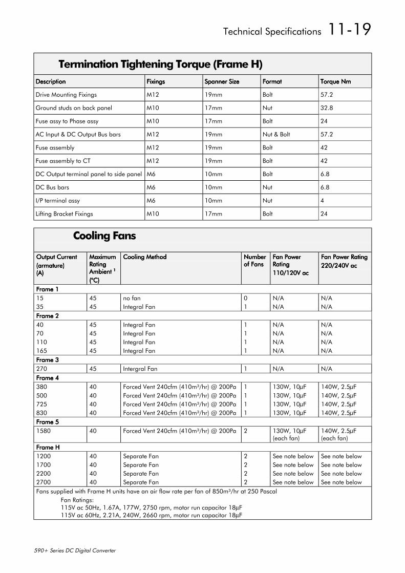
Technical Specifications 11-19
590+ Series DC Digital Converter
Termination Tightening Torque (Frame H)DescriptionDescriptionDescriptionDescription FixingsFixingsFixingsFixings Spanner SizeSpanner SizeSpanner SizeSpanner Size FormatFormatFormatFormat Torque NmTorque NmTorque NmTorque Nm
Drive Mounting Fixings M12 19mm Bolt 57.2
Ground studs on back panel M10 17mm Nut 32.8
Fuse assy to Phase assy M10 17mm Bolt 24
AC Input & DC Output Bus bars M12 19mm Nut & Bolt 57.2
Fuse assembly M12 19mm Bolt 42
Fuse assembly to CT M12 19mm Bolt 42
DC Output terminal panel to side panel M6 10mm Bolt 6.8
DC Bus bars M6 10mm Nut 6.8
I/P terminal assy M6 10mm Nut 4
Lifting Bracket Fixings M10 17mm Bolt 24
Cooling Fans
Output CurrentOutput CurrentOutput CurrentOutput Current(armature)(armature)(armature)(armature)(A)(A)(A)(A)
MaximumMaximumMaximumMaximumRatingRatingRatingRatingAmbient Ambient Ambient Ambient 1111
(°C)(°C)(°C)(°C)
Cooling MethodCooling MethodCooling MethodCooling Method NumberNumberNumberNumberof Fansof Fansof Fansof Fans
Fan PowerFan PowerFan PowerFan PowerRatingRatingRatingRating110/120V ac110/120V ac110/120V ac110/120V ac
Fan Power RatingFan Power RatingFan Power RatingFan Power Rating220/240V ac220/240V ac220/240V ac220/240V ac
Frame 1Frame 1Frame 1Frame 115 45 no fan 0 N/A N/A35 45 Integral Fan 1 N/A N/AFrame 2Frame 2Frame 2Frame 240 45 Integral Fan 1 N/A N/A70 45 Integral Fan 1 N/A N/A110 45 Integral Fan 1 N/A N/A165 45 Integral Fan 1 N/A N/AFrame 3Frame 3Frame 3Frame 3270 45 Intergral Fan 1 N/A N/AFrame 4Frame 4Frame 4Frame 4380 40 Forced Vent 240cfm (410m³/hr) @ 200Pa 1 130W, 10µF 140W, 2.5µF500 40 Forced Vent 240cfm (410m³/hr) @ 200Pa 1 130W, 10µF 140W, 2.5µF725 40 Forced Vent 240cfm (410m³/hr) @ 200Pa 1 130W, 10µF 140W, 2.5µF830 40 Forced Vent 240cfm (410m³/hr) @ 200Pa 1 130W, 10µF 140W, 2.5µFFrame 5Frame 5Frame 5Frame 51580 40 Forced Vent 240cfm (410m³/hr) @ 200Pa 2 130W, 10µF
(each fan)140W, 2.5µF(each fan)
Frame HFrame HFrame HFrame H1200 40 Separate Fan 2 See note below See note below1700 40 Separate Fan 2 See note below See note below2200 40 Separate Fan 2 See note below See note below2700 40 Separate Fan 2 See note below See note belowFans supplied with Frame H units have an air flow rate per fan of 850m³/hr at 250 Pascal
Fan Ratings:115V ac 50Hz, 1.67A, 177W, 2750 rpm, motor run capacitor 18µF115V ac 60Hz, 2.21A, 240W, 2660 rpm, motor run capacitor 18µF
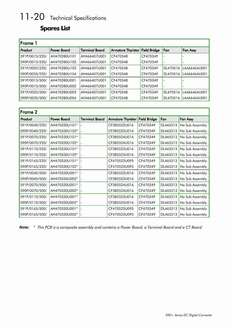
11-20 Technical Specifications
590+ Series DC Digital Converter
Spares List
Frame 1Frame 1Frame 1Frame 1ProductProductProductProduct Power BoardPower BoardPower BoardPower Board Terminal BoardTerminal BoardTerminal BoardTerminal Board Armature ThyristorArmature ThyristorArmature ThyristorArmature Thyristor Field BridgeField BridgeField BridgeField Bridge FanFanFanFan Fan AssyFan AssyFan AssyFan Assy
591P/0015/220/ AH470280U101 AH466407U001 CF470348 CF470349 - -
590P/0015/220/ AH470280U102 AH466407U001 CF470348 CF470349 - -
591P/0035/220/ AH470280U103 AH466407U001 CF470348 CF470349 DL470516 LA466464U001
590P/0035/220/ AH470280U104 AH466407U001 CF470348 CF470349 DL470516 LA466464U001
591P/0015/500/ AH470280U001 AH466407U001 CF470348 CF470349 - -
590P/0015/500/ AH470280U002 AH466407U001 CF470348 CF470349 - -
591P/0035/500/ AH470280U003 AH466407U001 CF470348 CF470349 DL470516 LA466464U001
590P/0035/500/ AH470280U004 AH466407U001 CF470348 CF470349 DL470516 LA466464U001
Frame 2Frame 2Frame 2Frame 2ProductProductProductProduct Power BoardPower BoardPower BoardPower Board Terminal BoardTerminal BoardTerminal BoardTerminal Board Armature ThyristorArmature ThyristorArmature ThyristorArmature Thyristor Field BridgeField BridgeField BridgeField Bridge FanFanFanFan Fan AssyFan AssyFan AssyFan Assy
591P/0040/220/ AH470330U101* - CF385522U016 CF470349 DL465313 No Sub Assembly
590P/0040/220/ AH470330U102* - CF385522U016 CF470349 DL465313 No Sub Assembly
591P/0070/220/ AH470330U101* - CF385524U016 CF470349 DL465313 No Sub Assembly
590P/0070/220/ AH470330U102* - CF385524U016 CF470349 DL465313 No Sub Assembly
591P/0110/220/ AH470330U101* - CF385525U016 CF470349 DL465313 No Sub Assembly
590P/0110/220/ AH470330U102* - CF385525U016 CF470349 DL465313 No Sub Assembly
591P/0165/220/ AH470330U101* - CF470523U095 CF470349 DL465313 No Sub Assembly
590P/0165/220/ AH470330U102* - CF470523U095 CF470349 DL465313 No Sub Assembly
591P/0040/500/ AH470330U001* - CF385522U016 CF470349 DL465313 No Sub Assembly
590P/0040/500/ AH470330U002* - CF385522U016 CF470349 DL465313 No Sub Assembly
591P/0070/500/ AH470330U001* - CF385524U016 CF470349 DL465313 No Sub Assembly
590P/0070/500/ AH470330U002* - CF385524U016 CF470349 DL465313 No Sub Assembly
591P/0110/500/ AH470330U001* - CF385525U016 CF470349 DL465313 No Sub Assembly
590P/0110/500/ AH470330U002* - CF385525U016 CF470349 DL465313 No Sub Assembly
591P/0165/500/ AH470330U001* - CF470523U095 CF470349 DL465313 No Sub Assembly
590P/0165/500/ AH470330U002* - CF470523U095 CF470349 DL465313 No Sub Assembly
Note: * This PCB is a composite assembly and contains a Power Board, a Terminal Board and a CT Board
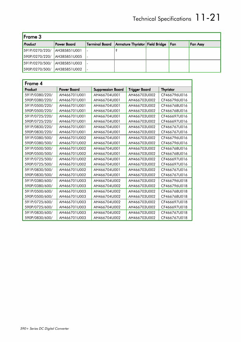
Technical Specifications 11-21
590+ Series DC Digital Converter
Frame 3Frame 3Frame 3Frame 3ProductProductProductProduct Power BoardPower BoardPower BoardPower Board Terminal BoardTerminal BoardTerminal BoardTerminal Board Armature ThyristorArmature ThyristorArmature ThyristorArmature Thyristor Field BridgeField BridgeField BridgeField Bridge FanFanFanFan Fan AssyFan AssyFan AssyFan Assy
591P/0270/220/ AH385851U001 - ?
590P/0270/220/ AH385851U005 -
591P/0270/500/ AH385851U003 -
590P/0270/500/ AH385851U002 -
Frame 4Frame 4Frame 4Frame 4ProductProductProductProduct Power BoardPower BoardPower BoardPower Board Suppression BoardSuppression BoardSuppression BoardSuppression Board Trigger BoardTrigger BoardTrigger BoardTrigger Board ThyristorThyristorThyristorThyristor591P/0380/220/ AH466701U001 AH466704U001 AH466703U002 CF466796U016590P/0380/220/ AH466701U001 AH466704U001 AH466703U002 CF466796U016591P/0500/220/ AH466701U001 AH466704U001 AH466703U002 CF466768U016590P/0500/220/ AH466701U001 AH466704U001 AH466703U002 CF466768U016591P/0725/220/ AH466701U001 AH466704U001 AH466703U002 CF466697U016590P/0725/220/ AH466701U001 AH466704U001 AH466703U002 CF466697U016591P/0830/220/ AH466701U001 AH466704U001 AH466703U002 CF466767U016590P/0830/220/ AH466701U001 AH466704U001 AH466703U002 CF466767U016
591P/0380/500/ AH466701U002 AH466704U001 AH466703U002 CF466796U016590P/0380/500/ AH466701U002 AH466704U001 AH466703U002 CF466796U016591P/0500/500/ AH466701U002 AH466704U001 AH466703U002 CF466768U016590P/0500/500/ AH466701U002 AH466704U001 AH466703U002 CF466768U016591P/0725/500/ AH466701U002 AH466704U001 AH466703U002 CF466697U016590P/0725/500/ AH466701U002 AH466704U001 AH466703U002 CF466697U016591P/0830/500/ AH466701U002 AH466704U001 AH466703U002 CF466767U016590P/0830/500/ AH466701U002 AH466704U001 AH466703U002 CF466767U016
591P/0380/600/ AH466701U003 AH466704U002 AH466703U002 CF466796U018590P/0380/600/ AH466701U003 AH466704U002 AH466703U002 CF466796U018591P/0500/600/ AH466701U003 AH466704U002 AH466703U002 CF466768U018590P/0500/600/ AH466701U003 AH466704U002 AH466703U002 CF466768U018591P/0725/600/ AH466701U003 AH466704U002 AH466703U002 CF466697U018590P/0725/600/ AH466701U003 AH466704U002 AH466703U002 CF466697U018591P/0830/600/ AH466701U003 AH466704U002 AH466703U002 CF466767U018590P/0830/600/ AH466701U003 AH466704U002 AH466703U002 CF466767U018
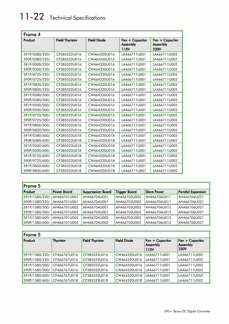
11-22 Technical Specifications
590+ Series DC Digital Converter
Frame 4Frame 4Frame 4Frame 4ProductProductProductProduct Field ThyristorField ThyristorField ThyristorField Thyristor Field DiodeField DiodeField DiodeField Diode Fan + CapacitorFan + CapacitorFan + CapacitorFan + Capacitor
AssemblyAssemblyAssemblyAssembly115V115V115V115V
Fan + CapacitorFan + CapacitorFan + CapacitorFan + CapacitorAssemblyAssemblyAssemblyAssembly230V230V230V230V
591P/0380/220/ CF385522U016 CW464320U016 LA466711U001 LA466711U002590P/0380/220/ CF385522U016 CW464320U016 LA466711U001 LA466711U002591P/0500/220/ CF385522U016 CW464320U016 LA466711U001 LA466711U002590P/0500/220/ CF385522U016 CW464320U016 LA466711U001 LA466711U002591P/0725/220/ CF385522U016 CW464320U016 LA466711U001 LA466711U002590P/0725/220/ CF385522U016 CW464320U016 LA466711U001 LA466711U002591P/0830/220/ CF385522U016 CW464320U016 LA466711U001 LA466711U002590P/0830/220/ CF385522U016 CW464320U016 LA466711U001 LA466711U002
591P/0380/500/ CF385522U016 CW464320U016 LA466711U001 LA466711U002590P/0380/500/ CF385522U016 CW464320U016 LA466711U001 LA466711U002591P/0500/500/ CF385522U016 CW464320U016 LA466711U001 LA466711U002590P/0500/500/ CF385522U016 CW464320U016 LA466711U001 LA466711U002591P/0725/500/ CF385522U016 CW464320U016 LA466711U001 LA466711U002590P/0725/500/ CF385522U016 CW464320U016 LA466711U001 LA466711U002591P/0830/500/ CF385522U016 CW464320U016 LA466711U001 LA466711U002590P/0830/500/ CF385522U016 CW464320U016 LA466711U001 LA466711U002
591P/0380/600/ CF385523U018 CW464320U018 LA466711U001 LA466711U002590P/0380/600/ CF385523U018 CW464320U018 LA466711U001 LA466711U002591P/0500/600/ CF385523U018 CW464320U018 LA466711U001 LA466711U002590P/0500/600/ CF385523U018 CW464320U018 LA466711U001 LA466711U002591P/0725/600/ CF385523U018 CW464320U018 LA466711U001 LA466711U002590P/0725/600/ CF385523U018 CW464320U018 LA466711U001 LA466711U002591P/0830/600/ CF385523U018 CW464320U018 LA466711U001 LA466711U002590P/0830/600/ CF385523U018 CW464320U018 LA466711U001 LA466711U002
Frame 5Frame 5Frame 5Frame 5ProductProductProductProduct Power BoardPower BoardPower BoardPower Board Suppression BoardSuppression BoardSuppression BoardSuppression Board Trigger BoardTrigger BoardTrigger BoardTrigger Board Slave PowerSlave PowerSlave PowerSlave Power Parallel ExpansionParallel ExpansionParallel ExpansionParallel Expansion591P/1580/220/ AH466701U001 AH466704U001 AH466703U002 AH466706U011 AH466706U021590P/1580/220/ AH466701U001 AH466704U001 AH466703U002 AH466706U011 AH466706U021
591P/1580/500/ AH466701U002 AH466704U001 AH466703U002 AH466706U012 AH466706U021590P/1580/500/ AH466701U002 AH466704U001 AH466703U002 AH466706U012 AH466706U021
591P/1580/600/ AH466701U003 AH466704U002 AH466703U002 AH466706U013 AH466706U021590P/1580/600/ AH466701U003 AH466704U002 AH466703U002 AH466706U013 AH466706U021
Frame 5Frame 5Frame 5Frame 5ProductProductProductProduct ThyristorThyristorThyristorThyristor Field ThyristorField ThyristorField ThyristorField Thyristor Field DiodeField DiodeField DiodeField Diode Fan + CapacitorFan + CapacitorFan + CapacitorFan + Capacitor
AssemblyAssemblyAssemblyAssembly115V115V115V115V
Fan + CapacitorFan + CapacitorFan + CapacitorFan + CapacitorAssemblyAssemblyAssemblyAssembly230V230V230V230V
591P/1580/220/ CF466767U016 CF385522U016 CW464320U016 LA466711U001 LA466711U002590P/1580/220/ CF466767U016 CF385522U016 CW464320U016 LA466711U001 LA466711U002
591P/1580/500/ CF466767U016 CF385522U016 CW464320U016 LA466711U001 LA466711U002590P/1580/500/ CF466767U016 CF385522U016 CW464320U016 LA466711U001 LA466711U002
591P/1580/600/ CF466767U018 CF385523U018 CW464320U018 LA466711U001 LA466711U002590P/1580/600/ CF466767U018 CF385523U018 CW464320U018 LA466711U001 LA466711U002
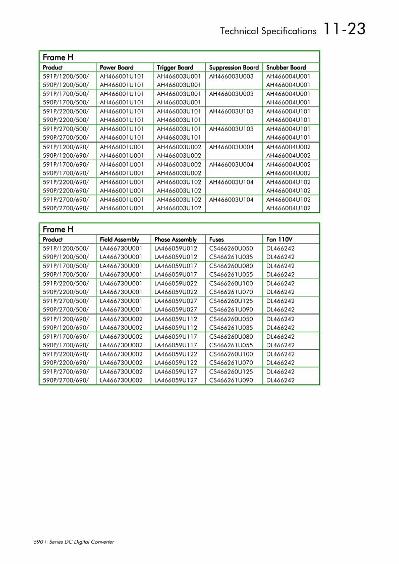
Technical Specifications 11-23
590+ Series DC Digital Converter
Frame HFrame HFrame HFrame HProductProductProductProduct Power BoardPower BoardPower BoardPower Board Trigger BoardTrigger BoardTrigger BoardTrigger Board Suppression BoardSuppression BoardSuppression BoardSuppression Board Snubber BoardSnubber BoardSnubber BoardSnubber Board591P/1200/500/ AH466001U101 AH466003U001 AH466003U003 AH466004U001590P/1200/500/ AH466001U101 AH466003U001 AH466004U001591P/1700/500/ AH466001U101 AH466003U001 AH466003U003 AH466004U001590P/1700/500/ AH466001U101 AH466003U001 AH466004U001591P/2200/500/ AH466001U101 AH466003U101 AH466003U103 AH466004U101590P/2200/500/ AH466001U101 AH466003U101 AH466004U101591P/2700/500/ AH466001U101 AH466003U101 AH466003U103 AH466004U101590P/2700/500/ AH466001U101 AH466003U101 AH466004U101
591P/1200/690/ AH466001U001 AH466003U002 AH466003U004 AH466004U002590P/1200/690/ AH466001U001 AH466003U002 AH466004U002591P/1700/690/ AH466001U001 AH466003U002 AH466003U004 AH466004U002590P/1700/690/ AH466001U001 AH466003U002 AH466004U002591P/2200/690/ AH466001U001 AH466003U102 AH466003U104 AH466004U102590P/2200/690/ AH466001U001 AH466003U102 AH466004U102591P/2700/690/ AH466001U001 AH466003U102 AH466003U104 AH466004U102590P/2700/690/ AH466001U001 AH466003U102 AH466004U102
Frame HFrame HFrame HFrame HProductProductProductProduct Field AssemblyField AssemblyField AssemblyField Assembly Phase AssemblyPhase AssemblyPhase AssemblyPhase Assembly FusesFusesFusesFuses Fan 110VFan 110VFan 110VFan 110V591P/1200/500/ LA466730U001 LA466059U012 CS466260U050 DL466242590P/1200/500/ LA466730U001 LA466059U012 CS466261U035 DL466242591P/1700/500/ LA466730U001 LA466059U017 CS466260U080 DL466242590P/1700/500/ LA466730U001 LA466059U017 CS466261U055 DL466242591P/2200/500/ LA466730U001 LA466059U022 CS466260U100 DL466242590P/2200/500/ LA466730U001 LA466059U022 CS466261U070 DL466242591P/2700/500/ LA466730U001 LA466059U027 CS466260U125 DL466242590P/2700/500/ LA466730U001 LA466059U027 CS466261U090 DL466242
591P/1200/690/ LA466730U002 LA466059U112 CS466260U050 DL466242590P/1200/690/ LA466730U002 LA466059U112 CS466261U035 DL466242591P/1700/690/ LA466730U002 LA466059U117 CS466260U080 DL466242590P/1700/690/ LA466730U002 LA466059U117 CS466261U055 DL466242591P/2200/690/ LA466730U002 LA466059U122 CS466260U100 DL466242590P/2200/690/ LA466730U002 LA466059U122 CS466261U070 DL466242591P/2700/690/ LA466730U002 LA466059U127 CS466260U125 DL466242590P/2700/690/ LA466730U002 LA466059U127 CS466261U090 DL466242

11-24 Technical Specifications
590+ Series DC Digital Converter

Certification for the Converter 12-1
590+ Series DC Digital Converter
12 CERTIFICATION FOR THE CONVERTERCaution
The integration of this product into other apparatus or systems is not the responsibility ofEurotherm Drives, with respect to applicability, effectivity, or safety of operation of the
other apparatus or systems.
Requirements for EMC ComplianceAll Variable Speed Drives (VSDs) potentially produce electrical emissions which are radiatedinto the environment and conducted back into the ac supply. VSDs are inherently immune to anyadditional external electrical noise. The following information is provided to maximise theElectro Magnetic Compatibility (EMC) of VSDs and systems in their intended operatingenvironment, by minimising their emissions and maximising their immunity.
Minimising Radiated EmissionsEN55011/EN55022 radiated emission measurements are made between 30MHz and 1GHz in thefar field at a distance of 10 to 30 metres (32.8 to 98.4 feet). Limits lower than 30MHz or in closeproximity are not specified. Emissions from individual components tend to be additive.
• Use a screened/armoured cable between VSD/cubicle and motor containing the motorprotective earth (PE) connection. It should have a 360° screen termination. Earth screen atboth ends connecting to the motor frame and VSD/cubicle backplate. Maintain the screenintegrity using 360° terminations.
Note: Some hazardous area installations may preclude direct earthing at both ends of thescreen, in this case earth one end via a 1µF 50Vac capacitor, and the other must bedirectly earthed.
• Keep unshielded cable as short as possible inside the cubicle.
• Always maintain the integrity of the shield.
• If the cable is interrupted to insert contactors etc., re-connect the screen using the shortestpossible route.
• Keep the length of screen stripped-back as short as possible when making screenconnections.
• Ideally use 360° screen terminations using cable glands or `U’ clips on power screen rails.
If a shielded cable is not available, lay unshielded motor cables in a metal conduit which will actas a shield. The conduit must be continuous with a direct electrical contact to the VSD and motorhousing. If links are necessary, use braid with a minimum cross sectional area of 10mm2.
Note: Some motor gland boxes, conduit and conduit glands are made of plastic, if this is thecase, then braid must be connected in parallel to maintain screen integrity. In addition atthe motor end, ensure that the screen is electrically connected to the motor frame sincesome terminal boxes are insulated from the frame by gasket/paint.
Earthing RequirementsIMPORTANT: Protective earthing always takes precedence over EMC earthing.
Protective Earth (PE) ConnectionsNote: In accordance with installations to EN60204, only one protective earth conductor is
permitted at each VSD protective earth terminal contacting point.
Local wiring regulations may require the protective earth connection of the motor to beconnected locally, i.e. not as specified in these instructions. This will not cause shieldingproblems because of the relatively high RF impedance of the local earth connection.
12-2 Certification for the Converter
590+ Series DC Digital Converter
Control/Signal EMC Earth ConnectionsFor compliance with EN60204 and EMC requirements, the “0V/signal ground” must beseparately earthed. When a number of units are used in a system, these terminals should beconnected together at a single, local earthing point.
Control and signal cables for the encoder, all analogue inputs, and communications requirescreening with the screen connected only at the VSD end. However, if high frequency noise isstill a problem, earth screen at the non VSD end via a 0.1µF, 50Vac capacitor.
Note: Connect the screen (at the VSD end) to the VSD protective point, and not to the controlboard terminals.
Cabling RequirementsNote: Refer to Chapter 11: “Technical Specifications” for additional Cabling Requirements.
Planning Cable Runs• Use the shortest possible motor cable lengths.
• Keep electrically noisy and sensitive cables apart.
• Keep electrically noisy and sensitive parallel cable runs to a minimum. Separate parallelcable runs by at least 0.25 metres (0.8 feet). For runs longer than 10 metres (32.8 feet),separation should be increased proportionally. For example if the parallel runs were 50m(164 feet), then the separation would be (50/10) x 0.25m = 1.25m (164/32.8 x 0.8 = 4 feet).
• Sensitive cables should cross noisy cables at 90°.
• Never run sensitive cables close or parallel to the motor cable for any distance.
• Never run supply or motor cables in the same bundle as the signal/control and feedbackcables, even if they are screened.
• Ensure EMC filter input and output cables are separately routed and do not couple noiseacross the filter (i.e. bypass the filter).
Increasing Motor Cable LengthBecause cable capacitance and hence conducted emissions increase with motor cable length,conformance to EMC limits is only guaranteed with the specified ac supply filter option using amaximum cable length as specified in Chapter 11: “Technical Specifications”.
Screened/armoured cable has significant capacitance between the conductors and screen whichincreases linearly with cable length (typically 200pF/m but varies with cable type and currentrating).
Long cable lengths may have the following undesirable effects:
• Producing increased conducted emissions which degrade the performance of the EMC filterdue to saturation.
• Causing RCDs (Residual Current Devices) to trip due to increased high frequency earthcurrent.
• Producing increased heating inside the EMC ac supply filter from the increased conductedemissions.
These effects can be overcome by adding chokes at the output of the VSD.
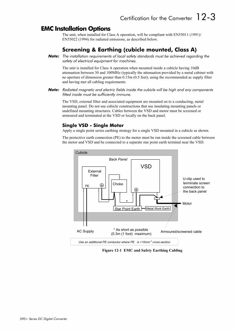
Certification for the Converter 12-3
590+ Series DC Digital Converter
EMC Installation OptionsThe unit, when installed for Class A operation, will be compliant with EN55011 (1991)/EN55022 (1994) for radiated emissions, as described below.
Screening & Earthing (cubicle mounted, Class A)Note: The installation requirements of local safety standards must be achieved regarding the
safety of electrical equipment for machines.
The unit is installed for Class A operation when mounted inside a cubicle having 10dBattenuation between 30 and 100MHz (typically the attenuation provided by a metal cabinet withno aperture of dimension greater than 0.15m (0.5 feet), using the recommended ac supply filterand having met all cabling requirements.
Note: Radiated magnetic and electric fields inside the cubicle will be high and any componentsfitted inside must be sufficiently immune.
The VSD, external filter and associated equipment are mounted on to a conducting, metalmounting panel. Do not use cubicle constructions that use insulating mounting panels orundefined mounting structures. Cables between the VSD and motor must be screened orarmoured and terminated at the VSD or locally on the back panel.
Single VSD - Single MotorApply a single point series earthing strategy for a single VSD mounted in a cubicle as shown.
The protective earth connection (PE) to the motor must be run inside the screened cable betweenthe motor and VSD and be connected to a separate star point earth terminal near the VSD.
VSDBack Panel
Cubicle
Motor
AC Supply
U-clip used to terminate screenconnection tothe back panel
Armoured/screened cable* As short as possible(0.3m (1 foot) maximum)
ExternalFilter
PE Choke
Use an additional PE conductor where PE is <10mm cross-section2
Star Point Earth Metal Work Earth
*
Figure 12-1 EMC and Safety Earthing Cabling
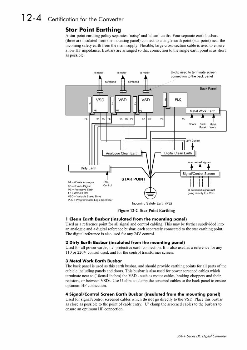
12-4 Certification for the Converter
590+ Series DC Digital Converter
Star Point EarthingA star-point earthing policy separates `noisy’ and `clean’ earths. Four separate earth busbars(three are insulated from the mounting panel) connect to a single earth point (star point) near theincoming safety earth from the main supply. Flexible, large cross-section cable is used to ensurea low HF impedance. Busbars are arranged so that connection to the single earth point is as shortas possible.
Doors Metal Work
110VControl
24V Control
unscreened signals
STAR POINT
Incoming Safety Earth (PE)
Analogue Clean Earth
Dirty Earth
Digital Clean Earth
Signal/Control Screen
all screened signals not
Back Panel
U-clip used to terminate screenconnection to the back panel
PE = Protective Earth
0A = 0 Volts Analogue0D = 0 Volts Digital
f = External FilterVSD = Variable Speed DrivePLC = Programmable Logic Controller
going directly to a VSD
Metal Work Earth
BackPanel
PLC
PE PE PE0D 0D 0D 0D0A 0A 0A
to motor to motor to motor
screened screened
PE
VSD VSDVSDf f f
f
PEPEPE
Figure 12-2 Star Point Earthing
1 Clean Earth Busbar (insulated from the mounting panel)Used as a reference point for all signal and control cabling. This may be further subdivided intoan analogue and a digital reference busbar, each separately connected to the star earthing point.The digital reference is also used for any 24V control.
2 Dirty Earth Busbar (insulated from the mounting panel)Used for all power earths, i.e. protective earth connection. It is also used as a reference for any110 or 220V control used, and for the control transformer screen.
3 Metal Work Earth BusbarThe back panel is used as this earth busbar, and should provide earthing points for all parts of thecubicle including panels and doors. This busbar is also used for power screened cables whichterminate near to (10cm/4 inches) the VSD - such as motor cables, braking choppers and theirresistors, or between VSDs. Use U-clips to clamp the screened cables to the back panel to ensureoptimum HF connection.
4 Signal/Control Screen Earth Busbar (insulated from the mounting panel)Used for signal/control screened cables which do not go directly to the VSD. Place this busbaras close as possible to the point of cable entry. `U’ clamp the screened cables to the busbars toensure an optimum HF connection.

Certification for the Converter 12-5
590+ Series DC Digital Converter
Sensitive EquipmentThe proximity of the source and victim circuit has a large effect on radiated coupling. Theelectromagnetic fields produced by VSDs falls off rapidly with distance from the cabling/cubicle.Remember that the radiated fields from EMC compliant drive systems are measured at least 10mfrom the equipment, over the band 30-1000MHz. Any equipment placed closer than this will seelarger magnitude fields, especially when very close to the Converter.
Do not place magnetic/electric field sensitive equipment within 0.25 metres (0.8 feet) of thefollowing parts of the VSD system:
• Variable Speed Drive (VSD)
• Input or output chokes/transformers
• The cable between VSD and motor (even when screened/armoured)
• AC/DC brushed motors (due to commutation)
• Relays and contactors (even when suppressed)
From experience, the following equipment is particularly sensitive and requires carefulinstallation.
• Any transducers which produce low level analogue outputs (<1V) , e.g. load cells, straingauges, thermocouples, piezoelectric transducers, anemometers, LVDTs
• Wide band width control inputs (>100Hz)
• AM radios (long and medium wave only)
• Video cameras and closed circuit TV
• Office personal computers
• Capacitive devices such as proximity sensors and level transducers
• Mains borne communication systems
• Equipment not suitable for operation in the intended EMC environment, i.e. with insufficientimmunity to new EMC standards
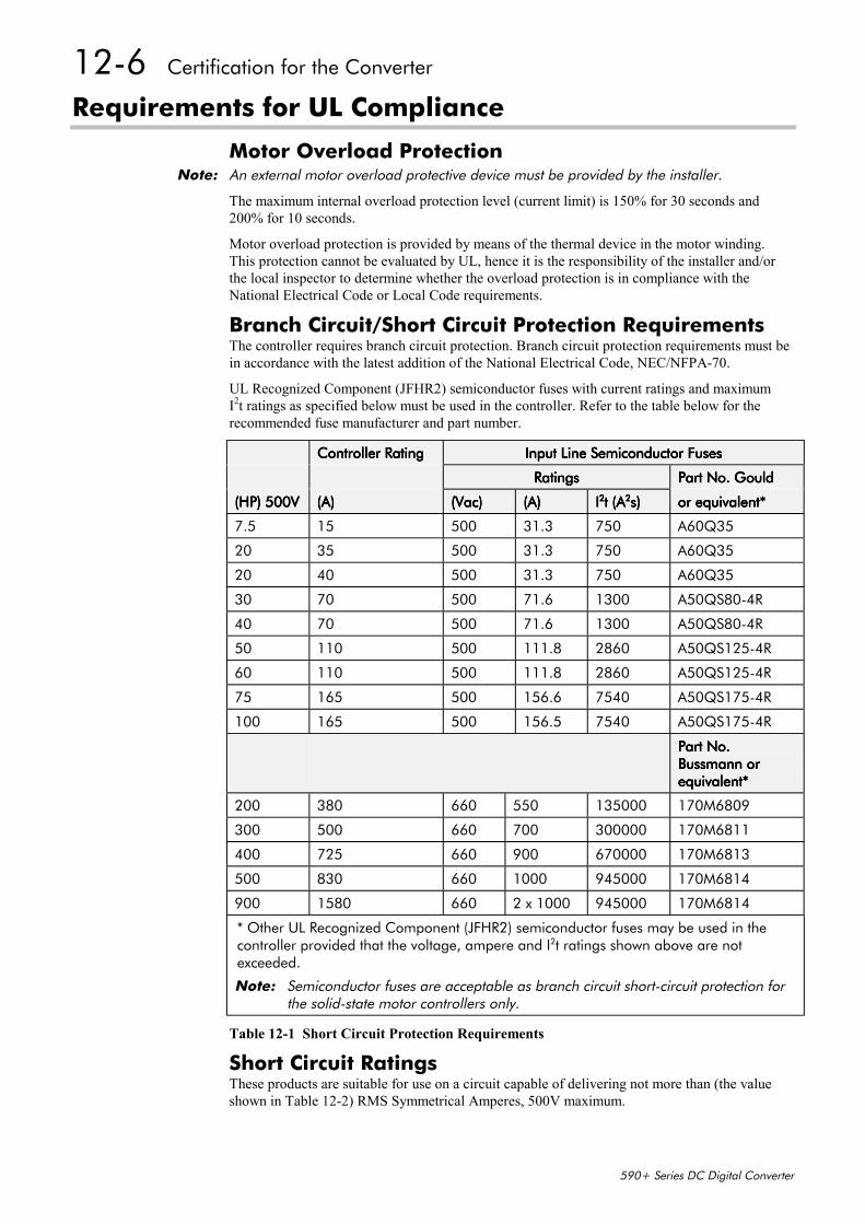
12-6 Certification for the Converter
590+ Series DC Digital Converter
Requirements for UL Compliance
Motor Overload ProtectionNote: An external motor overload protective device must be provided by the installer.
The maximum internal overload protection level (current limit) is 150% for 30 seconds and200% for 10 seconds.
Motor overload protection is provided by means of the thermal device in the motor winding.This protection cannot be evaluated by UL, hence it is the responsibility of the installer and/orthe local inspector to determine whether the overload protection is in compliance with theNational Electrical Code or Local Code requirements.
Branch Circuit/Short Circuit Protection RequirementsThe controller requires branch circuit protection. Branch circuit protection requirements must bein accordance with the latest addition of the National Electrical Code, NEC/NFPA-70.
UL Recognized Component (JFHR2) semiconductor fuses with current ratings and maximumI2t ratings as specified below must be used in the controller. Refer to the table below for therecommended fuse manufacturer and part number.
Controller RatingController RatingController RatingController Rating Input Line Semiconductor FusesInput Line Semiconductor FusesInput Line Semiconductor FusesInput Line Semiconductor Fuses
RatingsRatingsRatingsRatings Part No. GouldPart No. GouldPart No. GouldPart No. Gould
(HP) 500V(HP) 500V(HP) 500V(HP) 500V (A)(A)(A)(A) (Vac)(Vac)(Vac)(Vac) (A)(A)(A)(A) IIII2222t (At (At (At (A2222s)s)s)s) or equivalent*or equivalent*or equivalent*or equivalent*
7.5 15 500 31.3 750 A60Q35
20 35 500 31.3 750 A60Q35
20 40 500 31.3 750 A60Q35
30 70 500 71.6 1300 A50QS80-4R
40 70 500 71.6 1300 A50QS80-4R
50 110 500 111.8 2860 A50QS125-4R
60 110 500 111.8 2860 A50QS125-4R
75 165 500 156.6 7540 A50QS175-4R
100 165 500 156.5 7540 A50QS175-4R
Part No.Part No.Part No.Part No.Bussmann orBussmann orBussmann orBussmann orequivalent*equivalent*equivalent*equivalent*
200 380 660 550 135000 170M6809
300 500 660 700 300000 170M6811
400 725 660 900 670000 170M6813
500 830 660 1000 945000 170M6814
900 1580 660 2 x 1000 945000 170M6814
* Other UL Recognized Component (JFHR2) semiconductor fuses may be used in thecontroller provided that the voltage, ampere and I2t ratings shown above are notexceeded.
Note: Semiconductor fuses are acceptable as branch circuit short-circuit protection forthe solid-state motor controllers only.
Table 12-1 Short Circuit Protection Requirements
Short Circuit RatingsThese products are suitable for use on a circuit capable of delivering not more than (the valueshown in Table 12-2) RMS Symmetrical Amperes, 500V maximum.

Certification for the Converter 12-7
590+ Series DC Digital Converter
Output RatingsOutput RatingsOutput RatingsOutput Ratings Short Circuit RatingShort Circuit RatingShort Circuit RatingShort Circuit Rating(A)(A)(A)(A) (kW ) 500V(kW ) 500V(kW ) 500V(kW ) 500V RMS Symmetrical AmperesRMS Symmetrical AmperesRMS Symmetrical AmperesRMS Symmetrical Amperes15 7.5 5,00035 15 5,00040 15 10,00070 30 10,000110 45 10,000165 75 10,000380 150 18000500 225 18000725 327 30000830 335 300001580 650 85000
Table 12-2 Short Circuit Ratings
Field Wiring Temperature RatingUse 75°C copper conductors only.
Operating Ambient TemperatureFor the operating ambient temperature range, refer to Chapter 11: “Technical Specifications”.
Field Wiring Terminal MarkingsFor the correct field wiring connections that are to be made to each terminal, refer to Chapter 3:“Installing the Converter” - Electrical Installation.
Power and Control Field Wiring TerminalsFor the correct tightening torque value, refer to Chapter 11: “Technical Specifications”.
Field Grounding TerminalsThe field grounding terminal(s) is identified with the International Grounding Symbol(IEC) Publication 417, Symbol 5019.
Field Terminal KitsUL compliant terminal kits are available for the connection of power wiring for the followingConverter ratings. These terminals must be applied with the correct tooling as described in theInstallation Instructions provided with each terminal kit.
Kit Part NumberKit Part NumberKit Part NumberKit Part Number ControllerControllerControllerControllerRating (A)Rating (A)Rating (A)Rating (A)
NumberNumberNumberNumberof Lugsof Lugsof Lugsof Lugs
PurposePurposePurposePurpose Lugs perLugs perLugs perLugs perTerminalTerminalTerminalTerminal
Wire Size per LugWire Size per LugWire Size per LugWire Size per Lug CableCableCableCableRatingRatingRatingRating
LA386000U380 380 32
ACDC
11
2 x 4/0 AWG2 x 250kcmil
230A255A
LA386000U500 500 32
ACDC
11
2 x 300kcmil2 x 350kcmil
285A310A
LA386000U725 725 34
ACDC
12
2 x 600kcmil2 x 4/0 AWG
420A230A
LA386000U830 830 64
ACDC
22
2 x 250kcmil2 x 300kcmil
255A285A
Note: 1580A controller requires two LA386000U830 kits.
Fuse Replacement InformationFor fuse replacement information, refer to Chapter 11: “Technical Specifications”.
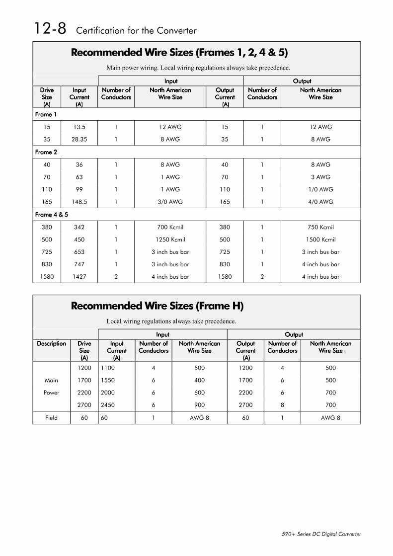
12-8 Certification for the Converter
590+ Series DC Digital Converter
Recommended Wire Sizes (Frames 1, 2, 4 & 5)Main power wiring. Local wiring regulations always take precedence.
InputInputInputInput OutputOutputOutputOutput
DriveDriveDriveDriveSizeSizeSizeSize(A)(A)(A)(A)
InputInputInputInputCurrentCurrentCurrentCurrent
(A)(A)(A)(A)
Number ofNumber ofNumber ofNumber ofConductorsConductorsConductorsConductors
North AmericanNorth AmericanNorth AmericanNorth AmericanWire SizeWire SizeWire SizeWire Size
OutputOutputOutputOutputCurrentCurrentCurrentCurrent
(A) (A) (A) (A)
Number ofNumber ofNumber ofNumber ofConductorsConductorsConductorsConductors
North AmericanNorth AmericanNorth AmericanNorth AmericanWire SizeWire SizeWire SizeWire Size
Frame 1Frame 1Frame 1Frame 1
15 13.5 1 12 AWG 15 1 12 AWG
35 28.35 1 8 AWG 35 1 8 AWG
Frame 2Frame 2Frame 2Frame 2
40 36 1 8 AWG 40 1 8 AWG
70 63 1 1 AWG 70 1 3 AWG
110 99 1 1 AWG 110 1 1/0 AWG
165 148.5 1 3/0 AWG 165 1 4/0 AWG
Frame 4 & 5Frame 4 & 5Frame 4 & 5Frame 4 & 5
380 342 1 700 Kcmil 380 1 750 Kcmil
500 450 1 1250 Kcmil 500 1 1500 Kcmil
725 653 1 3 inch bus bar 725 1 3 inch bus bar
830 747 1 3 inch bus bar 830 1 4 inch bus bar
1580 1427 2 4 inch bus bar 1580 2 4 inch bus bar
Recommended Wire Sizes (Frame H)Local wiring regulations always take precedence.
InputInputInputInput OutputOutputOutputOutput
DescriptionDescriptionDescriptionDescription DriveDriveDriveDriveSizeSizeSizeSize(A)(A)(A)(A)
InputInputInputInputCurrentCurrentCurrentCurrent
(A)(A)(A)(A)
Number ofNumber ofNumber ofNumber ofConductorsConductorsConductorsConductors
North AmericanNorth AmericanNorth AmericanNorth AmericanWire SizeWire SizeWire SizeWire Size
OutputOutputOutputOutputCurrentCurrentCurrentCurrent
(A) (A) (A) (A)
Number ofNumber ofNumber ofNumber ofConductorsConductorsConductorsConductors
North AmericanNorth AmericanNorth AmericanNorth AmericanWire SizeWire SizeWire SizeWire Size
1200 1100 4 500 1200 4 500
Main 1700 1550 6 400 1700 6 500
Power 2200 2000 6 600 2200 6 700
2700 2450 6 900 2700 8 700
Field 60 60 1 AWG 8 60 1 AWG 8
Certification for the Converter 12-9
590+ Series DC Digital Converter
European Directives and the CE MarkThe following information is supplied to provide a basic understanding of the EMC and lowvoltage directives CE marking requirements. The following literature is recommended for furtherinformation:
• Recommendations for Application of Power Drive Systems (PDS), European CouncilDirectives - CE Marking and Technical Standardisation - (CEMEP)
Available from your local trade association or Eurotherm Drives office
• EMC Installation Guidelines for Modules and Systems - (Eurotherm Drives)
Available from your local Eurotherm Drives office, part number HA388879
• Short Form Overview of European Directives for Variable Speed Drives and Applications -(Eurotherm Drives)
Available from your local Eurotherm Drives office, part number HA389770
The European machines and drives manufacturers via their national trade associations haveformed the European Committee of Manufacturers of Electrical Machines and Power Electronics(CEMEP). Eurotherm Drives and other major European drives manufacturers are working to theCEMEP recommendations on CE marking. The CE mark shows that a product complies with therelevant EU directives, in our case the Low Voltage Directive and, in some instances, the EMCDirective.
CE Marking for Low Voltage DirectiveWhen installed in accordance with this manual, the 590+ Series Converter is CE marked byEurotherm Drives Ltd in accordance with the low voltage directive (S.I. No. 3260 implementsthis LVD directive into UK law). An EC Declaration of Conformity (low voltage directive) isincluded at the end of this chapter.
CE Marking for EMC - Who is Responsible?Note: The specified EMC emission and immunity performance of this unit can only be achieved
when the unit is installed to the EMC Installation Instructions given in this manual.
According to S.I. No. 2373 which implements the EMC directive into UK law, the requirementfor CE marking this unit falls into two categories:
1. Where the supplied unit has an intrinsic/direct function to the end user, then the unit isclassed as relevant apparatus.
2. Where the supplied unit is incorporated into a higher system/apparatus or machine whichincludes (at least) the motor, cable and a driven load but is unable to function without thisunit, then the unit is classed as a component.
Relevant Apparatus - Eurotherm Drives ResponsibilityOccasionally, say in a case where an existing fixed speed motor - such as a fan or pump - isconverted to variable speed with an add-on drive module (relevant apparatus), it becomes theresponsibility of Eurotherm Drives to apply the CE mark and issue an EC Declaration ofConformity for the EMC Directive. This declaration and the CE mark is included at the end ofthis chapter.
Component - Customer ResponsibilityThe majority of Eurotherm Drives’ products are classed as components and therefore we cannotapply the CE mark or produce an EC Declaration of Conformity in respect of EMC. It istherefore the manufacturer/supplier/installer of the higher system/apparatus or machine who mustconform to the EMC directive and CE mark.
12-10 Certification for the Converter
590+ Series DC Digital Converter
Legal Requirements for CE MarkingIMPORTANT: Before installation, clearly understand who is responsible for conformance with the EMC
directive. Misappropriation of the CE mark is a criminal offence.
It is important that you have now defined who is responsible for conforming to the EMCdirective, either:
Eurotherm Drives ResponsibilityYou intend to use the unit as relevant apparatus.
When the specified EMC filter is correctly fitted to the unit following EMC installationinstructions, it complies with the relevant standards indicated in the following tables. The fittingof the filter is mandatory for the CE marking of this unit to apply.
The relevant declarations are to be found at the end of this chapter. The CE mark is displayed onthe EC Declaration of Conformity (EMC Directive) provided at the end of this chapter.
Customer ResponsibilityYou intend to use the unit as a component, therefore you have a choice:
1. To fit the specified filter following EMC installation instructions, which may help you gainEMC compliance for the final machine/system.
2. Not to fit the specified filter, but use a combination of global or local filtering and screeningmethods, natural migration through distance, or the use of distributed parasitic elements ofthe existing installation.
Note: When two or more EMC compliant components are combined to form the finalmachine/system, the resulting machine/system may no longer be compliant, (emissionstend to be additive, immunity is determined by the least immune component). Understandthe EMC environment and applicable standards to keep additional compliance costs to aminimum.
Applying for CE Marking for EMCWe have supplied a Manufacturer’s EMC Declaration at the end of this chapter that you can useas a basis for your own justification of overall compliance with the EMC directive. There arethree methods of demonstrating conformity:
1. Self-certification to a relevant standard
2. Third party testing to a relevant standard
3. Writing a technical construction file stating the technical rationale as to why your finalmachine/system is compliant. An EMC “competent body” must then assess this and issue atechnical report or certificate to demonstrate compliance.Refer to Article 10(2) of Directive 89/336/EEC.
With EMC compliance, an EC Declaration of Conformity and the CE mark will be issued foryour final machine/system.
IMPORTANT: Professional end users with EMC expertise who are using drive modules and cubicleProfessional end users with EMC expertise who are using drive modules and cubicleProfessional end users with EMC expertise who are using drive modules and cubicleProfessional end users with EMC expertise who are using drive modules and cubiclesystems defined as components who supply, place on the market or install the relevantsystems defined as components who supply, place on the market or install the relevantsystems defined as components who supply, place on the market or install the relevantsystems defined as components who supply, place on the market or install the relevantapparatus must take responsibility for demonstrating EMC conformance and applying theapparatus must take responsibility for demonstrating EMC conformance and applying theapparatus must take responsibility for demonstrating EMC conformance and applying theapparatus must take responsibility for demonstrating EMC conformance and applying theCE mark and issuing an EC Declaration of Conformity.CE mark and issuing an EC Declaration of Conformity.CE mark and issuing an EC Declaration of Conformity.CE mark and issuing an EC Declaration of Conformity.
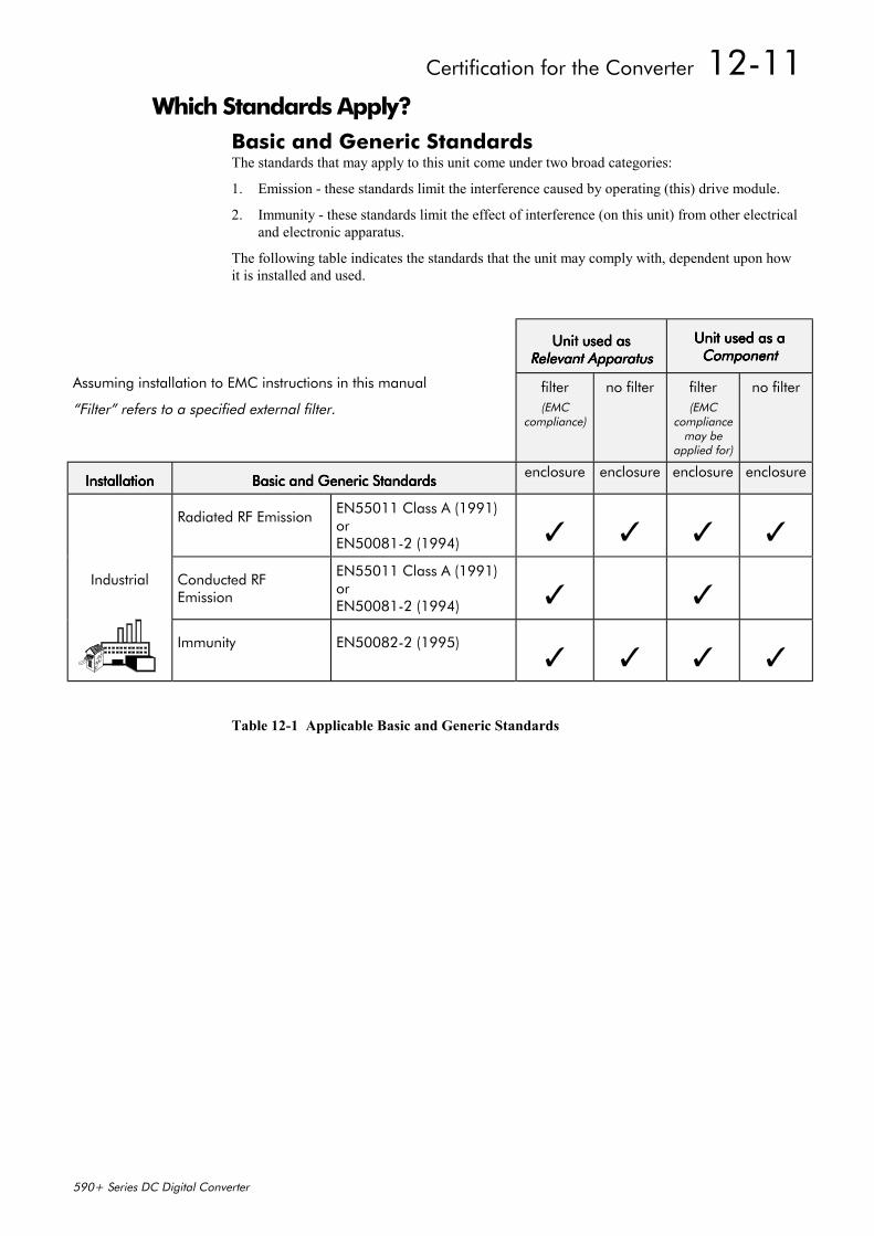
Certification for the Converter 12-11
590+ Series DC Digital Converter
Which Standards Apply?Basic and Generic StandardsThe standards that may apply to this unit come under two broad categories:
1. Emission - these standards limit the interference caused by operating (this) drive module.
2. Immunity - these standards limit the effect of interference (on this unit) from other electricaland electronic apparatus.
The following table indicates the standards that the unit may comply with, dependent upon howit is installed and used.
Unit used asUnit used asUnit used asUnit used asRelevant ApparatusRelevant ApparatusRelevant ApparatusRelevant Apparatus
Unit used as aUnit used as aUnit used as aUnit used as aComponentComponentComponentComponent
Assuming installation to EMC instructions in this manual
“Filter” refers to a specified external filter.filter(EMC
compliance)
no filter filter(EMC
compliancemay be
applied for)
no filter
InstallationInstallationInstallationInstallation Basic and Generic StandardsBasic and Generic StandardsBasic and Generic StandardsBasic and Generic Standardsenclosure enclosure enclosure enclosure
Radiated RF EmissionEN55011 Class A (1991)orEN50081-2 (1994)
Industrial Conducted RFEmission
EN55011 Class A (1991)orEN50081-2 (1994)
Immunity EN50082-2 (1995)
Table 12-1 Applicable Basic and Generic Standards
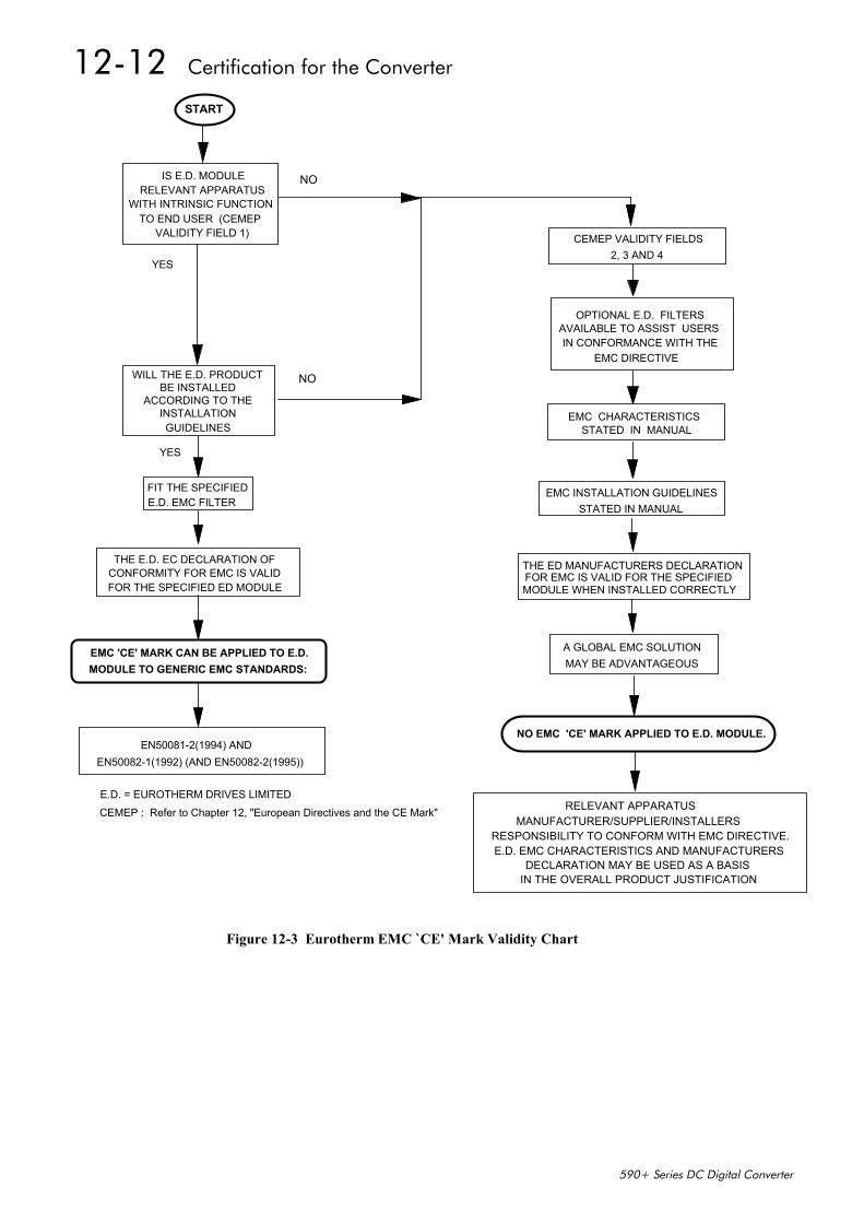
12-12 Certification for the Converter
590+ Series DC Digital Converter
THE E.D. EC DECLARATION OF CONFORMITY FOR EMC IS VALID FOR THE SPECIFIED ED MODULE
START
IS E.D. MODULE RELEVANT APPARATUS
WITH INTRINSIC FUNCTION TO END USER (CEMEP
VALIDITY FIELD 1)
NO
YES
FIT THE SPECIFIED E.D. EMC FILTER
WILL THE E.D. PRODUCT BE INSTALLED
ACCORDING TO THE INSTALLATIONGUIDELINES
NO
YES
E.D. = EUROTHERM DRIVES LIMITED
EMC 'CE' MARK CAN BE APPLIED TO E.D. MODULE TO GENERIC EMC STANDARDS:
EN50081-2(1994) ANDEN50082-1(1992) (AND EN50082-2(1995))
EMC CHARACTERISTICS STATED IN MANUAL
OPTIONAL E.D. FILTERS AVAILABLE TO ASSIST USERSIN CONFORMANCE WITH THE
EMC DIRECTIVE
EMC INSTALLATION GUIDELINESSTATED IN MANUAL
CEMEP VALIDITY FIELDS 2, 3 AND 4
NO EMC 'CE' MARK APPLIED TO E.D. MODULE.
A GLOBAL EMC SOLUTIONMAY BE ADVANTAGEOUS
MANUFACTURER/SUPPLIER/INSTALLERSRESPONSIBILITY TO CONFORM WITH EMC DIRECTIVE.E.D. EMC CHARACTERISTICS AND MANUFACTURERS
IN THE OVERALL PRODUCT JUSTIFICATION
RELEVANT APPARATUS
THE ED MANUFACTURERS DECLARATIONFOR EMC IS VALID FOR THE SPECIFIEDMODULE WHEN INSTALLED CORRECTLY
DECLARATION MAY BE USED AS A BASIS
CEMEP : Refer to Chapter 12, "European Directives and the CE Mark"
Figure 12-3 Eurotherm EMC `CE' Mark Validity Chart
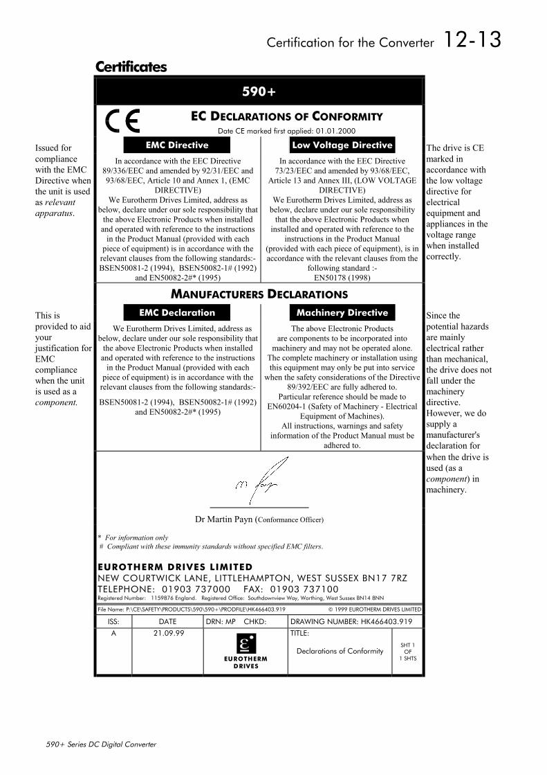
Certification for the Converter 12-13
590+ Series DC Digital Converter
Certificates
590+
EC DECLARATIONS OF CONFORMITYDate CE marked first applied: 01.01.2000
Issued for EMC Directive Low Voltage Directive The drive is CEcompliancewith the EMCDirective whenthe unit is usedas relevantapparatus.
In accordance with the EEC Directive89/336/EEC and amended by 92/31/EEC and93/68/EEC, Article 10 and Annex 1, (EMC
DIRECTIVE)We Eurotherm Drives Limited, address as
below, declare under our sole responsibility thatthe above Electronic Products when installed
and operated with reference to the instructionsin the Product Manual (provided with each
piece of equipment) is in accordance with therelevant clauses from the following standards:-BSEN50081-2 (1994), BSEN50082-1# (1992)
and EN50082-2#* (1995)
In accordance with the EEC Directive73/23/EEC and amended by 93/68/EEC,
Article 13 and Annex III, (LOW VOLTAGEDIRECTIVE)
We Eurotherm Drives Limited, address asbelow, declare under our sole responsibility
that the above Electronic Products wheninstalled and operated with reference to the
instructions in the Product Manual(provided with each piece of equipment), is inaccordance with the relevant clauses from the
following standard :-EN50178 (1998)
marked inaccordance withthe low voltagedirective forelectricalequipment andappliances in thevoltage rangewhen installedcorrectly.
MANUFACTURERS DECLARATIONS
This is EMC Declaration Machinery Directive Since theprovided to aidyourjustification forEMCcompliancewhen the unitis used as acomponent.
We Eurotherm Drives Limited, address asbelow, declare under our sole responsibility that
the above Electronic Products when installedand operated with reference to the instructions
in the Product Manual (provided with eachpiece of equipment) is in accordance with the
relevant clauses from the following standards:-
BSEN50081-2 (1994), BSEN50082-1# (1992)and EN50082-2#* (1995)
The above Electronic Productsare components to be incorporated into
machinery and may not be operated alone.The complete machinery or installation usingthis equipment may only be put into service
when the safety considerations of the Directive89/392/EEC are fully adhered to.
Particular reference should be made toEN60204-1 (Safety of Machinery - Electrical
Equipment of Machines).All instructions, warnings and safety
information of the Product Manual must beadhered to.
potential hazardsare mainlyelectrical ratherthan mechanical,the drive does notfall under themachinerydirective.However, we dosupply amanufacturer'sdeclaration forwhen the drive isused (as acomponent) inmachinery.
Dr Martin Payn (Conformance Officer)
* For information only # Compliant with these immunity standards without specified EMC filters.
EUROTHERM DRIVES LIMITEDNEW COURTWICK LANE, LITTLEHAMPTON, WEST SUSSEX BN17 7RZTELEPHONE: 01903 737000 FAX: 01903 737100Registered Number: 1159876 England. Registered Office: Southdownview Way, Worthing, West Sussex BN14 8NN
File Name: P:\CE\SAFETY\PRODUCTS\590\590+\PRODFILE\HK466403.919 © 1999 EUROTHERM DRIVES LIMITED
ISS: DATE DRN: MP CHKD: DRAWING NUMBER: HK466403.919
A 21.09.99
EUROTHERMDRIVES
TITLE:
Declarations of ConformitySHT 1
OF1 SHTS

12-14 Certification for the Converter
590+ Series DC Digital Converter
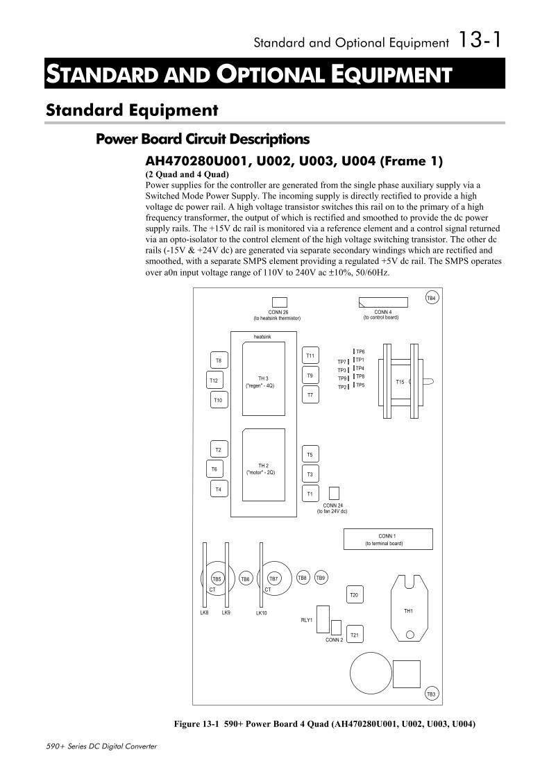
Standard and Optional Equipment 13-1
590+ Series DC Digital Converter
13 STANDARD AND OPTIONAL EQUIPMENT
Standard Equipment
Power Board Circuit DescriptionsAH470280U001, U002, U003, U004 (Frame 1)(2 Quad and 4 Quad)Power supplies for the controller are generated from the single phase auxiliary supply via aSwitched Mode Power Supply. The incoming supply is directly rectified to provide a highvoltage dc power rail. A high voltage transistor switches this rail on to the primary of a highfrequency transformer, the output of which is rectified and smoothed to provide the dc powersupply rails. The +15V dc rail is monitored via a reference element and a control signal returnedvia an opto-isolator to the control element of the high voltage switching transistor. The other dcrails (-15V & +24V dc) are generated via separate secondary windings which are rectified andsmoothed, with a separate SMPS element providing a regulated +5V dc rail. The SMPS operatesover a0n input voltage range of 110V to 240V ac ±10%, 50/60Hz.
CONN 26 CONN 4
TP6TP1TP4TP8TP5
TP7TP3TP9TP2
T15
T11
T9
T7
T8
T12
T10
T5
T3
T1
T2
T6
T4
CONN 24
TH 3
TH 2
TH1
T20
T21
TB3
RLY1
CONN 2
TB9TB8TB7TB6TB5
LK8 LK9 LK10
CONN 1
TB4
(to control board)(to heatsink thermistor)
heatsink
(to fan 24V dc)
(to terminal board)
("motor" - 2Q)
("regen" - 4Q)
CT CT
Figure 13-1 590+ Power Board 4 Quad (AH470280U001, U002, U003, U004)
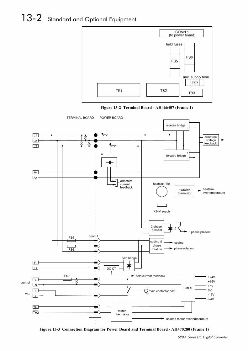
13-2 Standard and Optional Equipment
590+ Series DC Digital Converter
CONN 1
TB1 TB2 TB3
FS7
FS6FS5
field fuses
aux. supply fuse
(to power board)
Figure 13-2 Terminal Board - AH466407 (Frame 1)
A+
L1
L2
L3
A-
F+
F-
TH2
TH1
NL
4
3
forward bridge
reverse bridge
+
+
-
-
armaturevoltage
feedback
heatsinkthermistor
heatsinkovertemperature
heatsink fan
+24V supply
armature
coding &phase
rotation
coding
phase rotation
SMPS
+24V+15V+5V0V-15V-24V
main contactor pilot
field current feedback
field bridge
DC CT
motorthermistor
isolated motor overtemperature
FS6
FS5
FS7
conn 1
TERMINAL BOARD POWER BOARD
3 phasepresent 3 phase present
control
MC
currentfeedback
Figure 13-3 Connection Diagram for Power Board and Terminal Board - AH470280 (Frame 1)
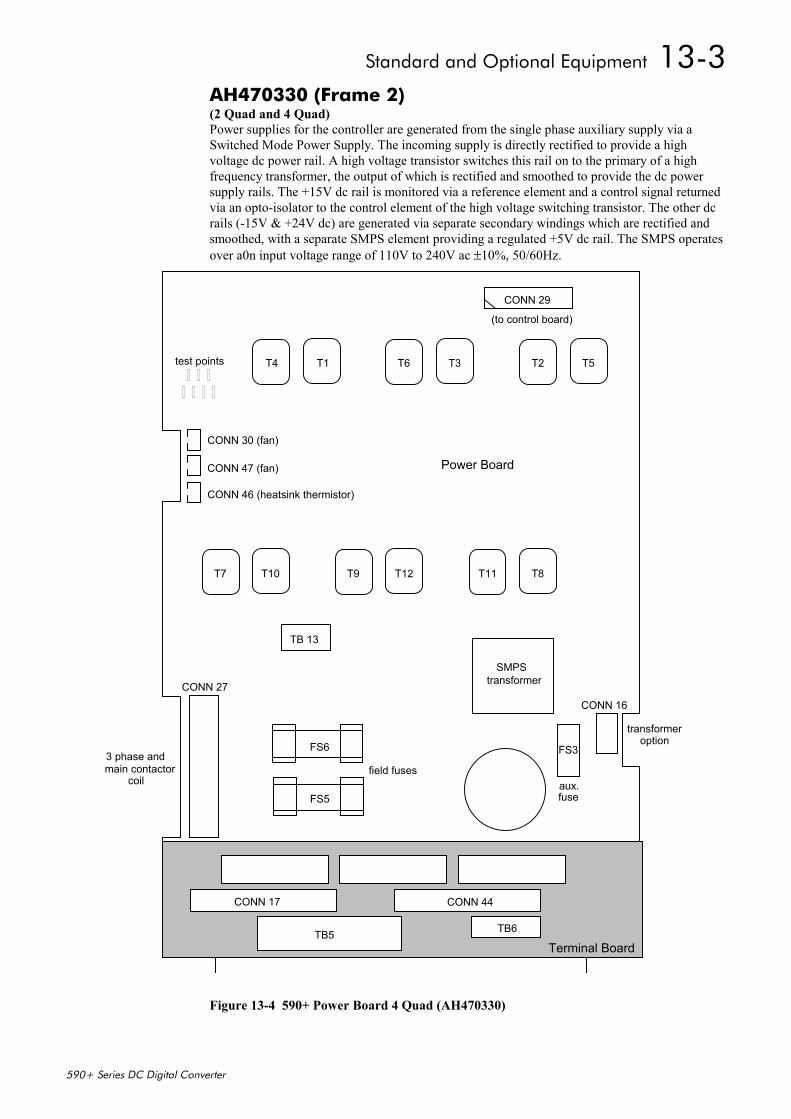
Standard and Optional Equipment 13-3
590+ Series DC Digital Converter
AH470330 (Frame 2)(2 Quad and 4 Quad)Power supplies for the controller are generated from the single phase auxiliary supply via aSwitched Mode Power Supply. The incoming supply is directly rectified to provide a highvoltage dc power rail. A high voltage transistor switches this rail on to the primary of a highfrequency transformer, the output of which is rectified and smoothed to provide the dc powersupply rails. The +15V dc rail is monitored via a reference element and a control signal returnedvia an opto-isolator to the control element of the high voltage switching transistor. The other dcrails (-15V & +24V dc) are generated via separate secondary windings which are rectified andsmoothed, with a separate SMPS element providing a regulated +5V dc rail. The SMPS operatesover a0n input voltage range of 110V to 240V ac ±10%, 50/60Hz.
CONN 29
T5T2T3T6T1T4
T8T11T12T9T10T7
test points
TB 13
CONN 30 (fan)
CONN 47 (fan)
CONN 46 (heatsink thermistor)
transformerSMPS
CONN 16CONN 27
FS6
FS5
FS3
(to control board)
3 phase andmain contactor
coilfield fuses
aux.fuse
transformeroption
CONN 17 CONN 44
TB5 TB6
Power Board
Terminal Board
Figure 13-4 590+ Power Board 4 Quad (AH470330)
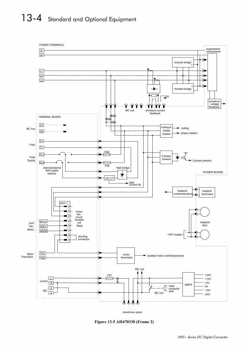
13-4 Standard and Optional Equipment
590+ Series DC Digital Converter
MC coil
forward bridge
reverse bridge
+
+
-
-
armaturevoltage
feedbackarmature current
coding &phase
rotation
coding
phase rotation
A+
L1
L2
L3
A-
POWER TERMINALS
POWER BOARD
3 phasepresent 3 phase present
field bridge
F+
F-
FS6
FS5
0V
suppressioncomponents
feedback
heatsinkthermistor
heatsinkovertemperature
heatsinkfans
+24V supply
isolated motor overtemperatureTH2
TH1 motorthermistor
+24V+15V+5V0V-15V-24VMC coil
MC coil
FS7
NL
4
3
control
MC
SMPS
transfomer option
motorfan
circuitbreaker
conn 1
M1/U
M2/V
M3/W
FL1
FL2
TERMINAL BOARD
maincontactorpilot
fieldcurrent f/b
DC CT
A1
internal/externalfield supply
selector
MC Aux
Field
FieldSupply
A2
notfitted
shortingconnector
VentFan
Motor
MotorThermistor
Figure 13-5 AH470330 (Frame 2)
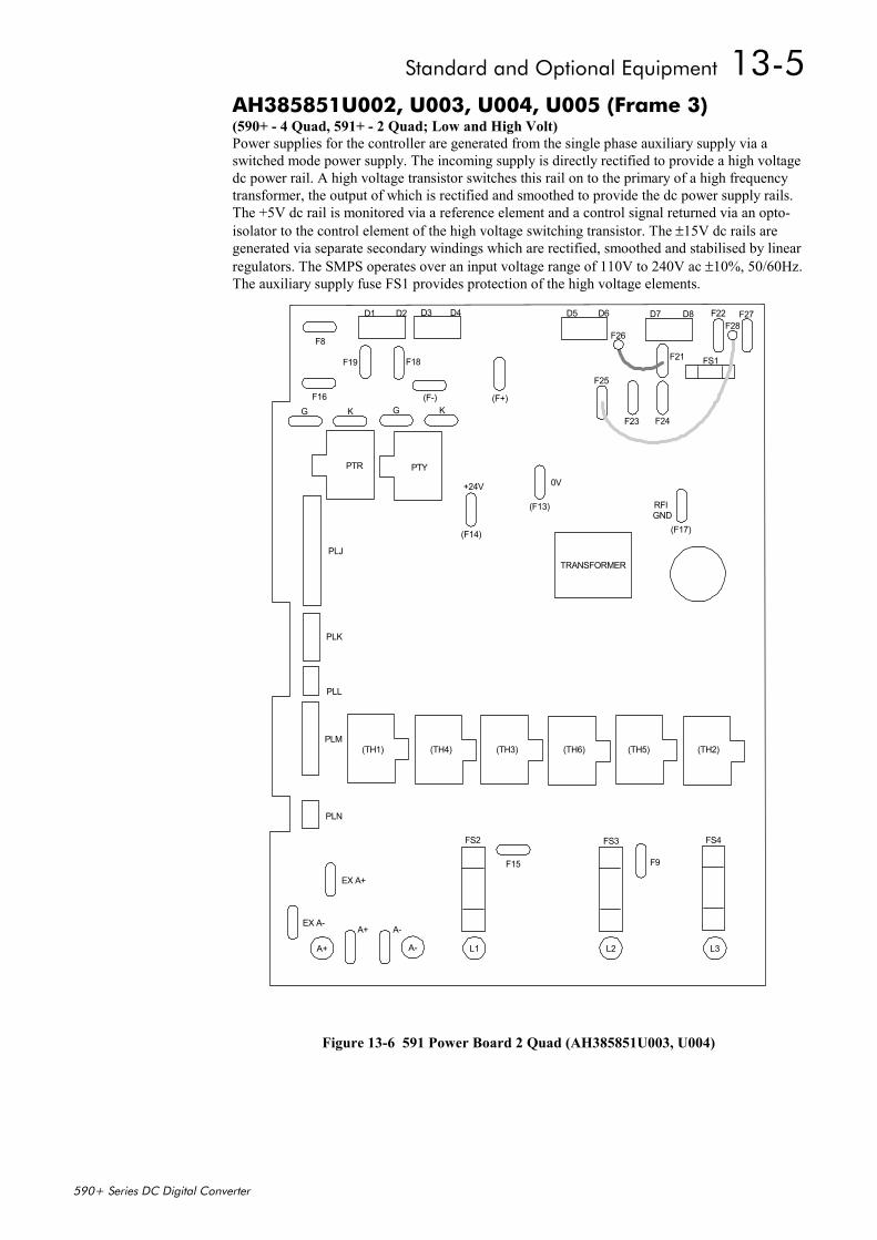
Standard and Optional Equipment 13-5
590+ Series DC Digital Converter
AH385851U002, U003, U004, U005 (Frame 3)(590+ - 4 Quad, 591+ - 2 Quad; Low and High Volt)Power supplies for the controller are generated from the single phase auxiliary supply via aswitched mode power supply. The incoming supply is directly rectified to provide a high voltagedc power rail. A high voltage transistor switches this rail on to the primary of a high frequencytransformer, the output of which is rectified and smoothed to provide the dc power supply rails.The +5V dc rail is monitored via a reference element and a control signal returned via an opto-isolator to the control element of the high voltage switching transistor. The ±15V dc rails aregenerated via separate secondary windings which are rectified, smoothed and stabilised by linearregulators. The SMPS operates over an input voltage range of 110V to 240V ac ±10%, 50/60Hz.The auxiliary supply fuse FS1 provides protection of the high voltage elements.
F8
F16G K G K
F19 F18
D1 D2 D3 D4
+24V 0V
RFIGND
F25
F23 F24
F21 FS1
F22 F27D5 D6 D7 D8
TRANSFORMER
PTR PTY
(F14)
(F13)
(F17)
(TH1) (TH4) (TH3) (TH6) (TH5) (TH2)
F15 F9
FS2 FS3 FS4
A-A+EX A-
EX A+
PLN
PLM
PLL
PLK
PLJ
(F+)(F-)
A+ A- L1 L2 L3
F26F28
Figure 13-6 591 Power Board 2 Quad (AH385851U003, U004)
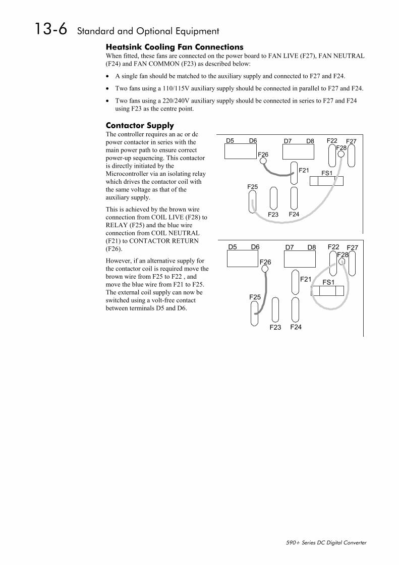
13-6 Standard and Optional Equipment
590+ Series DC Digital Converter
Heatsink Cooling Fan ConnectionsWhen fitted, these fans are connected on the power board to FAN LIVE (F27), FAN NEUTRAL(F24) and FAN COMMON (F23) as described below:
• A single fan should be matched to the auxiliary supply and connected to F27 and F24.
• Two fans using a 110/115V auxiliary supply should be connected in parallel to F27 and F24.
• Two fans using a 220/240V auxiliary supply should be connected in series to F27 and F24using F23 as the centre point.
Contactor SupplyThe controller requires an ac or dcpower contactor in series with themain power path to ensure correctpower-up sequencing. This contactoris directly initiated by theMicrocontroller via an isolating relaywhich drives the contactor coil withthe same voltage as that of theauxiliary supply.
This is achieved by the brown wireconnection from COIL LIVE (F28) toRELAY (F25) and the blue wireconnection from COIL NEUTRAL(F21) to CONTACTOR RETURN(F26).
However, if an alternative supply forthe contactor coil is required move thebrown wire from F25 to F22 , andmove the blue wire from F21 to F25.The external coil supply can now beswitched using a volt-free contactbetween terminals D5 and D6.
F25
F23 F24
F21 FS1
F22 F27D5 D6 D7 D8
F26F28
F25
F23 F24
F21 FS1
F22 F27D5 D6 D7 D8
F26F28
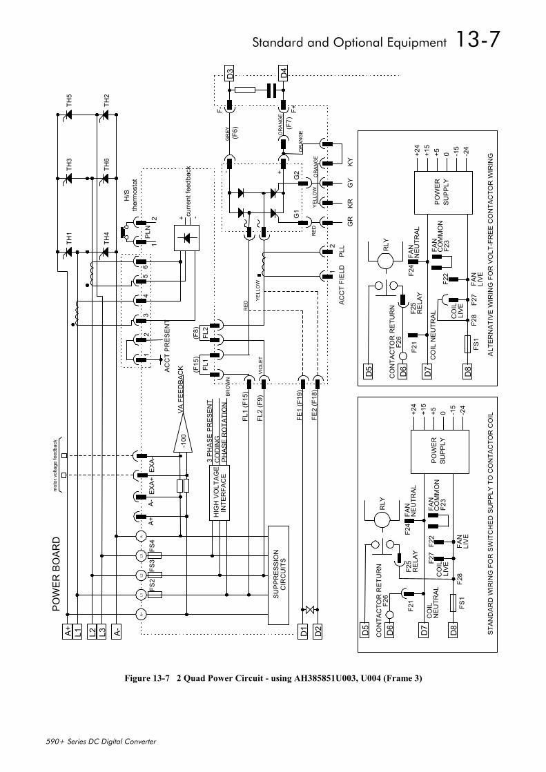
Standard and Optional Equipment 13-7
590+ Series DC Digital Converter
A+L1
L2L3
A-
A+ L1 L2 L3 A- D1
D2
FS2
FS3
FS4
D4
D3
TH2
TH5
TH6
TH3
TH4
TH1
mot
or v
olta
ge fe
edba
ck
H/S
ther
mos
tat
curr
ent f
eedb
ack
+ -
PLN
12
12
34
56
AC
CT
PR
ES
EN
T
EX
A+
-100
VA
FE
ED
BA
CK
A-
A+
HIG
H V
OLT
AG
EIN
TER
FAC
E
3 P
HA
SE
PR
ES
EN
TC
OD
ING
PH
AS
E R
OTA
TIO
N
(F15
)FL
1FL
2(F
8)
SU
PP
RE
SS
ION
CIR
CU
ITS
FL1
(F15
)
FL2
(F9)
FE1
(F19
)
FE2
(F18
)
RED
YELL
OW
VIO
LET
BRO
WN
RED
YELL
OW
OR
ANG
E
OR
ANG
EOR
ANG
E
(F7)
GR
EY(F
6)- +
G1
G2
F- F+
GR
KR
GY
KY
12
PLL
AC
CT
FIE
LD
D5
D6
D7
D8
CO
NTA
CTO
R R
ETU
RN
F26
F21
F25
REL
AYF2
4FA
NN
EU
TRA
L
FAN
CO
MM
ON
F23
F22
F27
CO
ILLI
VE
FAN
LIVE
F28
FS1
CO
ILN
EU
TRA
L
RLY
PO
WE
RS
UP
PLY
+24
+15
+5 0 -15
-24
D5
D6
D7
D8
CO
NTA
CTO
R R
ETU
RN
F26
F21
F25
REL
AYF2
4FA
NN
EU
TRA
L
FAN
CO
MM
ON
F23
F22
F27
CO
ILLI
VE
FAN
LIVE
F28
FS1
CO
IL N
EU
TRA
L
RLY
PO
WE
RS
UP
PLY
+24
+15
+5 0 -15
-24
POW
ER B
OAR
D
STA
ND
AR
D W
IRIN
G F
OR
SW
ITC
HE
D S
UP
PLY
TO
CO
NTA
CTO
R C
OIL
ALT
ER
NA
TIV
E W
IRIN
G F
OR
VO
LT-F
RE
E C
ON
TAC
TOR
WIR
ING
EX
A-
Figure 13-7 2 Quad Power Circuit - using AH385851U003, U004 (Frame 3)
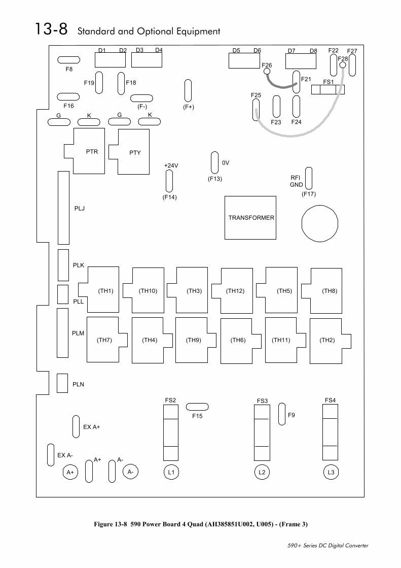
13-8 Standard and Optional Equipment
590+ Series DC Digital Converter
F8
F16G K G K
F19 F18
D1 D2 D3 D4
+24V 0V
RFIGND
F25
F23 F24
F21 FS1
F22 F27D5 D6 D7 D8
TRANSFORMER
PTR PTY
(F14)
(F13)
(F17)
(TH1) (TH10) (TH3) (TH12) (TH5) (TH8)
(TH7) (TH4) (TH9) (TH6) (TH11) (TH2)
F15 F9
FS2 FS3 FS4
A-A+EX A-
EX A+
PLN
PLM
PLL
PLK
PLJ
(F+)(F-)
A+ A- L1 L2 L3
F26F28
Figure 13-8 590 Power Board 4 Quad (AH385851U002, U005) - (Frame 3)
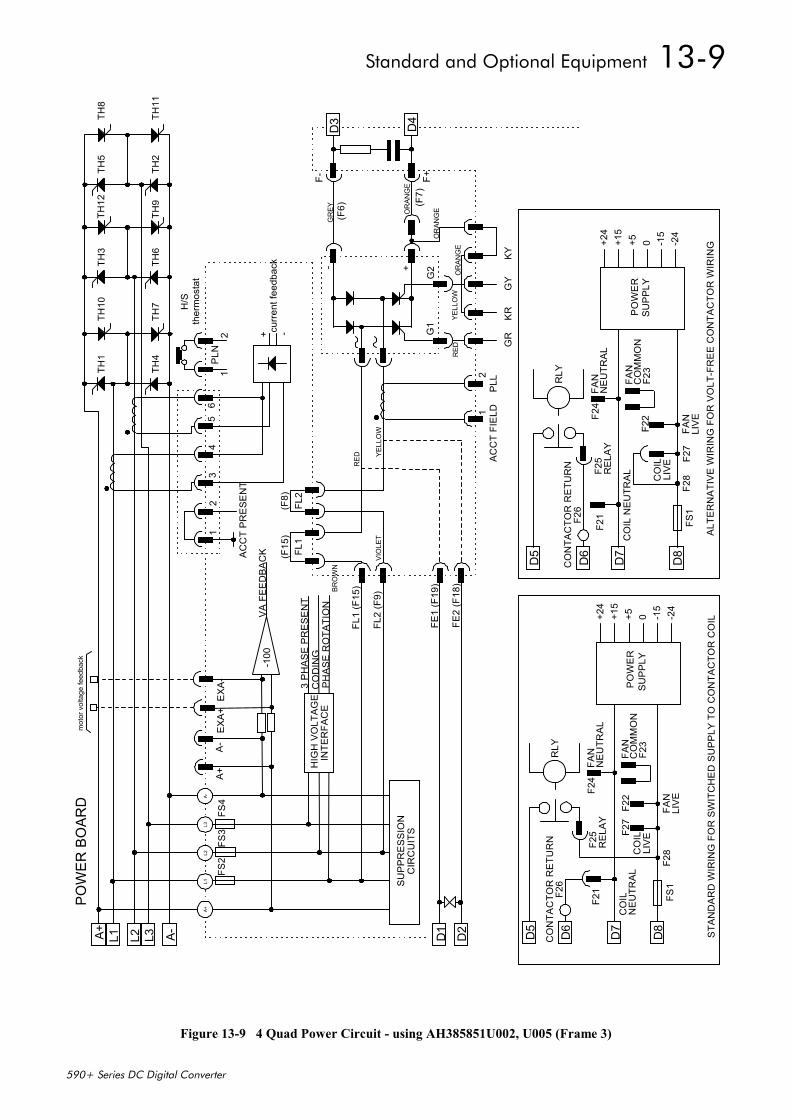
Standard and Optional Equipment 13-9
590+ Series DC Digital Converter
A+ L1 L2 L3 A- D1
D2
FS2
FS3
FS4
D4
D3TH
11
TH8
TH2
TH5
TH9
TH12
TH6
TH3
TH7
TH10
TH4
TH1
mot
or v
olta
ge fe
edba
ck
H/S
ther
mos
tat
curr
ent f
eedb
ack
+ -
PLN
12
12
34
56
AC
CT
PR
ES
EN
T
EX
A+
-100
VA
FE
ED
BA
CK
A-
A+
HIG
H V
OLT
AG
EIN
TER
FAC
E
3 P
HA
SE
PR
ES
EN
TC
OD
ING
PH
AS
E R
OTA
TIO
N
(F15
)FL
1FL
2(F
8)
SU
PP
RE
SS
ION
CIR
CU
ITS
FL1
(F15
)
FL2
(F9)
FE1
(F19
)
FE2
(F18
)
RED YE
LLO
WVI
OLE
T
BRO
WN
RED
YELL
OW
OR
ANG
E
OR
ANG
EOR
ANG
E
(F7)
GR
EY(F
6)- +
G1
G2
F- F+
GR
KR
GY
KY
12
PLL
AC
CT
FIE
LD
D5
D6
D7
D8
CO
NTA
CTO
R R
ETU
RN
F26
F21
F25
REL
AYF2
4FA
NN
EU
TRA
L
FAN
CO
MM
ON
F23
F22
F27
CO
ILLI
VE
FAN
LIVE
F28
FS1
CO
ILN
EU
TRA
L
RLY
PO
WE
RS
UP
PLY
+24
+15
+5 0 -15
-24
A+L1
L2L3
A-
D5
D6
D7
D8
CO
NTA
CTO
R R
ETU
RN
F26
F21
F25
REL
AYF2
4FA
NN
EU
TRA
L
FAN
CO
MM
ON
F23
F22
F27
CO
ILLI
VE
FAN
LIVE
F28
FS1
CO
IL N
EU
TRA
L
RLY
PO
WE
RS
UP
PLY
+24
+15
+5 0 -15
-24
POW
ER B
OAR
D
ALT
ER
NA
TIV
E W
IRIN
G F
OR
VO
LT-F
RE
E C
ON
TAC
TOR
WIR
ING
STA
ND
AR
D W
IRIN
G F
OR
SW
ITC
HE
D S
UP
PLY
TO
CO
NTA
CTO
R C
OIL
EX
A-
Figure 13-9 4 Quad Power Circuit - using AH385851U002, U005 (Frame 3)
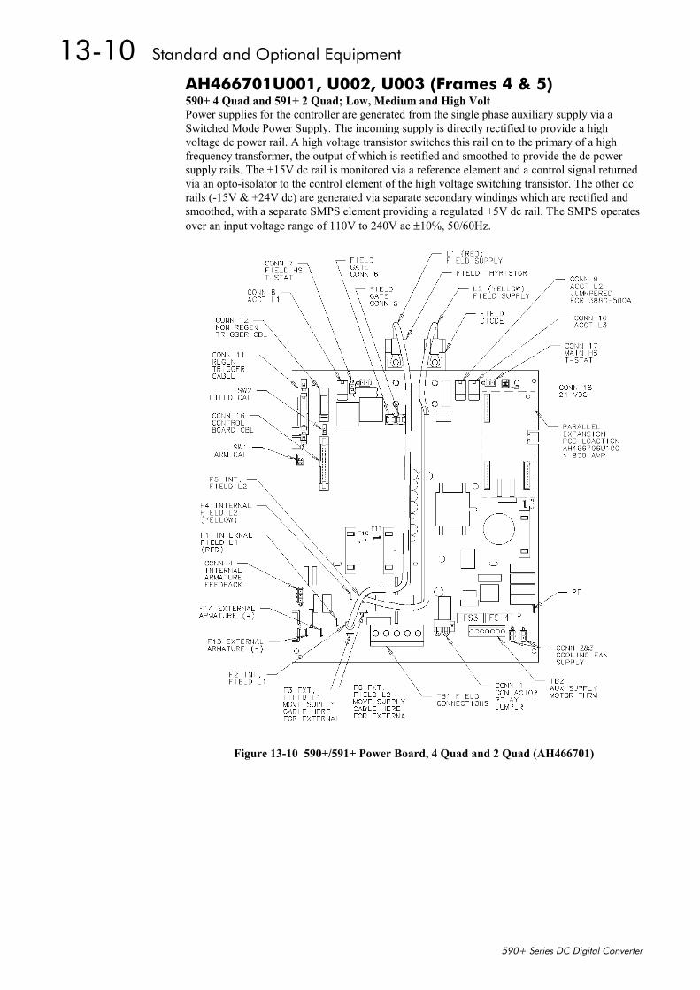
13-10 Standard and Optional Equipment
590+ Series DC Digital Converter
AH466701U001, U002, U003 (Frames 4 & 5)590+ 4 Quad and 591+ 2 Quad; Low, Medium and High VoltPower supplies for the controller are generated from the single phase auxiliary supply via aSwitched Mode Power Supply. The incoming supply is directly rectified to provide a highvoltage dc power rail. A high voltage transistor switches this rail on to the primary of a highfrequency transformer, the output of which is rectified and smoothed to provide the dc powersupply rails. The +15V dc rail is monitored via a reference element and a control signal returnedvia an opto-isolator to the control element of the high voltage switching transistor. The other dcrails (-15V & +24V dc) are generated via separate secondary windings which are rectified andsmoothed, with a separate SMPS element providing a regulated +5V dc rail. The SMPS operatesover an input voltage range of 110V to 240V ac ±10%, 50/60Hz.
Figure 13-10 590+/591+ Power Board, 4 Quad and 2 Quad (AH466701)
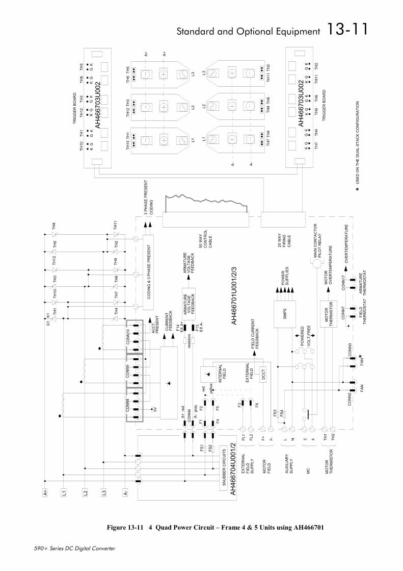
Standard and Optional Equipment 13-11
590+ Series DC Digital Converter
Figure 13-11 4 Quad Power Circuit – Frame 4 & 5 Units using AH466701
A+ L1 L2 L3 A-
TH1
TH4
TH5
TH2
TH3
TH6
ACC
T.G1
K1
TH9
TH12
TH7
TH10
TH11
TH8
TH1
TH10
TH3
TH12
TH5
TH8
L1L2
L3
A+ A+
TH7
TH4
TH9
TH6
TH11
TH2
L1L2
L3
A- A-
PRES
ENT
CU
RR
ENT
FEED
BAC
K
FS1
FS2
AH46
6704
U00
1/2
ARM
ATU
RE
VOLT
AGE
FEED
BAC
K
ARM
ATU
RE
VOLT
AGE
FEED
BAC
K
AH46
6701
U00
1/2/
3
0V
FIEL
D C
UR
REN
TFE
EDBA
CK
DC
CT
MO
TOR
THER
MIS
TOR
POW
ERED
VOLT
-FR
EE
SMPS
PO
WE
RSU
PPLI
ES
MO
TOR
OVE
RTE
MPE
RAT
UR
E
MAI
N C
ON
TAC
TOR
PILO
T R
ELAY
FAN
FAN
OVE
RTE
MPE
RAT
UR
E
ARM
ATU
RE
THER
MO
STAT
FIEL
DTH
ERM
OST
AT
CO
DIN
G &
3 P
HAS
E PR
ESEN
T3
PHAS
E PR
ESEN
T
50 W
AYC
ON
TRO
LC
ABLE
20 W
AYFI
RIN
GC
ABLE
AH46
6703
U00
2K
GK
GK
GK
GK
GK
G
TH7
TH4
TH9
TH6
TH11
TH2
AH46
6703
U00
2K
GK
GK
GK
GK
GK
G
TH10
TH1
TH12
TH3
TH8
TH5
FL1
FL2
L N
MC
TH1
TH2
MO
TOR
THER
MIS
TOR
AUXI
LIAR
YSU
PPLY
EXTE
RN
ALFI
ELD
SUPP
LY
F+ F-
MO
TOR
FIEL
D
TRIG
GER
BO
ARD
TRIG
GER
BO
ARD
CO
DIN
G
CO
NN
4
SNU
BBER
CIR
CU
ITS
F1F2
F4
A+ r
ed
red
yello
w
INTE
RN
ALFI
ELD
EXTE
RN
ALFI
ELD
F3 F6
FS3
FS4
3 4
CO
NN
2C
ON
N3
CO
NN
7C
ON
N17
**
USE
D O
N T
HE
DU
AL-S
TAC
K C
ON
FIG
UR
ATIO
N
CO
NN
8C
ON
N9
CO
NN
10
F5
A- g
ray
resi
stor
s
EX A
+
EX A
-
F14
F13
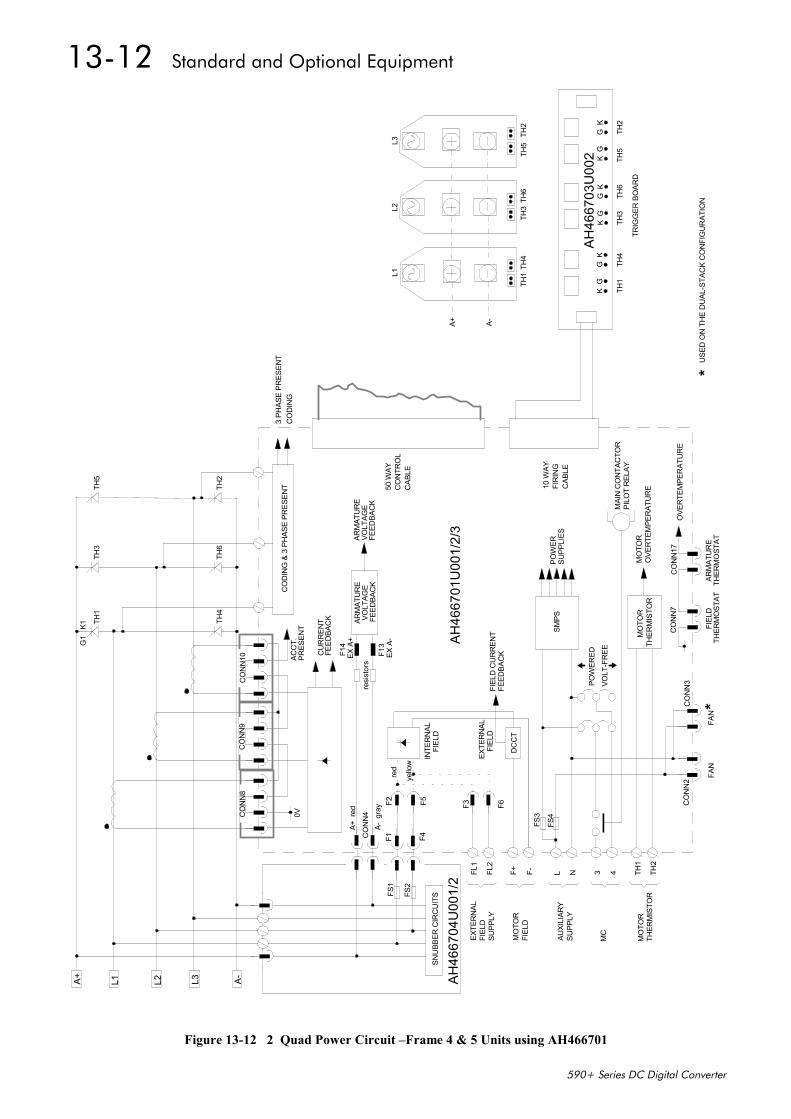
13-12 Standard and Optional Equipment
590+ Series DC Digital Converter
Figure 13-12 2 Quad Power Circuit –Frame 4 & 5 Units using AH466701
A+ L1 L2 L3 A-
TH1
TH4
TH5
TH2
TH3
TH6
ACC
T.G1
K1
TH1
TH4
TH3
TH6
TH5
TH2
L1L2
L3
A+ A-
PRES
ENT
CU
RR
ENT
FEED
BAC
K
FS1
FS2
AH
4667
04U
001/
2
ARM
ATU
RE
VOLT
AGE
FEED
BAC
K
ARM
ATU
RE
VOLT
AGE
FEED
BAC
K
AH
4667
01U
001/
2/3
0V
FIEL
D C
UR
REN
TFE
EDBA
CK
DC
CT
MO
TOR
THER
MIS
TOR
POW
ERED
VOLT
-FR
EE
SMPS
POW
ERSU
PPLI
ES
MO
TOR
OVE
RTE
MPE
RAT
UR
E
MAI
N C
ON
TAC
TOR
PILO
T R
ELAY
FAN
FAN
OVE
RTE
MPE
RAT
UR
E
ARM
ATU
RE
THER
MO
STAT
FIEL
DTH
ERM
OST
AT
CO
DIN
G &
3 P
HAS
E PR
ESEN
T3
PHAS
E PR
ESEN
T
50 W
AYC
ON
TRO
LC
ABLE
10 W
AYFI
RIN
GC
ABLE
AH
4667
03U
002
KG
KG
KG
KG
KG
KG
TH1
TH4
TH3
TH6
TH5
TH2
FL1
FL2
L N
MC
TH1
TH2
MO
TOR
THER
MIS
TOR
AUXI
LIAR
YSU
PPLY
EXTE
RN
ALFI
ELD
SUPP
LY
F+ F-
MO
TOR
FIEL
D
TRIG
GER
BO
ARD
CO
DIN
G
CO
NN
4
SNU
BBER
CIR
CU
ITS
F1F2
F4
A+ r
ed
red
yello
w
INTE
RN
ALFI
ELD
EXTE
RN
ALFI
ELD
F3 F6
FS3
FS4
3 4
CO
NN
2C
ON
N3
CO
NN
7C
ON
N17
**
USE
D O
N T
HE
DU
AL-S
TAC
K C
ON
FIG
UR
ATIO
N
CO
NN
8C
ON
N9
CO
NN
10
F5
A- g
ray
resi
stor
s
EX A
+
EX A
-
F14
F13
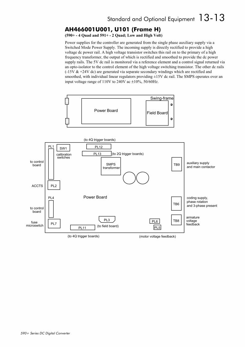
Standard and Optional Equipment 13-13
590+ Series DC Digital Converter
AH466001U001, U101 (Frame H)(590+ - 4 Quad and 591+ - 2 Quad; Low and High Volt)
Power supplies for the controller are generated from the single phase auxiliary supply via aSwitched Mode Power Supply. The incoming supply is directly rectified to provide a highvoltage dc power rail. A high voltage transistor switches this rail on to the primary of a highfrequency transformer, the output of which is rectified and smoothed to provide the dc powersupply rails. The 5V dc rail is monitored via a reference element and a control signal returned viaan opto-isolator to the control element of the high voltage switching transistor. The other dc rails(-15V & +24V dc) are generated via separate secondary windings which are rectified andsmoothed, with individual linear regulators providing ±15V dc rail. The SMPS operates over aninput voltage range of 110V to 240V ac ±10%, 50/60Hz.
Power Board Field Board
Swing-frame
TB9
TB6
TB8PL6
PL5
PL3
PL11
PL12
PL13
SMPStransformer
PL1
ACCTS PL2
calibrationswitches
SW1
PL4
PL7
(to 4Q trigger boards)
(to field board)
(motor voltage feedback)
armaturevoltagefeedback
coding supply, phase rotationand 3-phase present
auxiliary supplyand main contactor
(to 4Q trigger boards)
(to 2Q trigger boards)
to controlboard
to controlboard
fusemicroswitch
Power Board
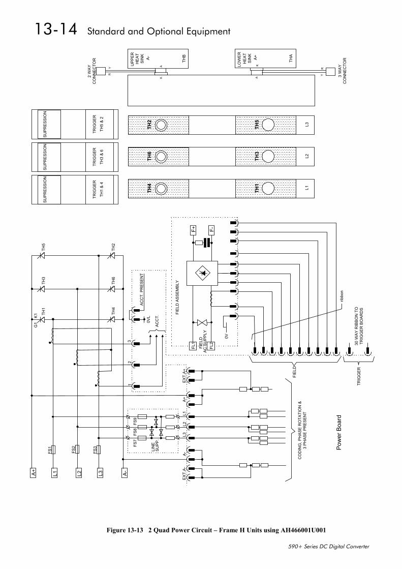
13-14 Standard and Optional Equipment
590+ Series DC Digital Converter
Figure 13-13 2 Quad Power Circuit – Frame H Units using AH466001U001
A+
L1 L2 L3 A-
TH3
TH1
TH5
TH2
TH6
TH4
F+ F-
ACC
T. P
RES
ENT
ACC
T.
0VL
30 W
AY R
IBBO
N T
OTR
IGG
ER B
OAR
DS
ribbo
n
FIEL
D A
SSEM
BLY
FIE
LDAC
SU
PPLY
EXT.
A+A+
L1L2
L3A-
EXT.
A-
FS1
FS2
FS3
12
3
G1
K1
FS7
FS8
FS9
LIN
ESU
PP.
FL1
FL2
0V
CO
DIN
G, P
HAS
E R
OTA
TIO
N &
3 PH
ASE
PRES
ENT
FIEL
D
TRIG
GER
TH
4
TH
1
L1
TH
6
TH
3
L2
TH
2
TH
5
L3
SUPR
ESSI
ON
TRIG
GER
TH1
& 4
SUPR
ESSI
ON
TRIG
GER
TH5
& 2
SUPR
ESSI
ON
TRIG
GER
TH3
& 6
UPP
ERH
EAT
SIN
KA-
RY
KA LO
WER
HEA
TSI
NK
A+A
K
THB
RY
THA
2 W
AYC
ON
NEC
TOR
3 W
AYC
ON
NEC
TOR
Pow
er B
oard
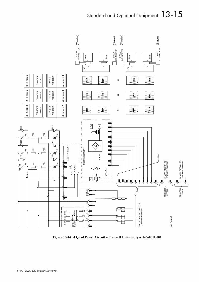
Standard and Optional Equipment 13-15
590+ Series DC Digital Converter
Figure 13-14 4 Quad Power Circuit – Frame H Units using AH466001U001
TH3
TH1
TH5
TH6
TH4
F+ F-
AC
CT.
PR
ES
EN
T
AC
CT.
0VL
26 W
AY
RIB
BO
N T
OTR
IGG
ER
BO
AR
DS
ribbo
n
FIE
LD A
SS
EM
BLY
FIE
LDA
C S
UP
PLY
EX
T.A
+A
+L1
L2L3
-
12
3
G1
K1
FS7
FS8
FS9
LIN
ES
UP
P.
FL1
FL2
0V
DIN
G, P
HA
SE
RO
TATI
ON
&3
PH
AS
E P
RE
SE
NT
FIE
LD
TRIG
GE
RU
PP
ER
TH2
TH11
TH8
TH9
TH7
TH12
TH10
FS1
FS3
FS5
FS4
FS6
FS2
TH
4
TH7
L1
TH
2
TH11 L3
TH
6
TH9
L2
THB
KA
2 W
AY
CO
NN
EC
TOR
AC
THA
AK
3 W
AY
CO
NN
EC
TOR
THA
AK
3 W
AY
CO
NN
EC
TOR
AC
THB
KA
2 W
AY
CO
NN
EC
TOR
BLA
NK
TRIG
GE
R
TH2
& 1
1
BLA
NK
TRIG
GE
R
TH5
& 8
BLA
NK
TRIG
GE
R
TH4
& 7
BLA
NK
TRIG
GE
R
TH1
& 1
0
BLA
NK
TRIG
GE
R
TH6
& 9
BLA
NK
TRIG
GE
R
TH3
& 1
2
26 W
AY
RIB
BO
N T
OTR
IGG
ER
BO
AR
DS
TRIG
GE
RLO
WE
R
wer
Boa
rd
TH
1
TH10
TH
5
TH8
TH
3
TH12
(Mas
ter)
(Sla
ve)
(Sla
ve)
(Mas
ter)

13-16 Standard and Optional Equipment
590+ Series DC Digital Converter
Optional EquipmentContact your local Eurotherm Drives office to order optional equipment.
ItemItemItemItem Part NumberPart NumberPart NumberPart Number
EMC Installation Guidelines for Modules and SystemsA Eurotherm Drives application manual detailing EMC requirements
HA388879
590 Digital Section ControlA Eurotherm Drives application manual detailing the use of theblock diagram to implement open and closed loop control of drivenweb section rolls
HA388664
590 Digital Closed Loop Centre WinderA Eurotherm Drives application manual detailing the use of theblock diagram to implement closed loop centre winders
HA388202
ConfigEd LiteEurotherm Drives’ Windows-based block programming software
Order by name
External AC Supply (RFI) FilterFor Converters without internal filters, on cable runs in excess of 25metres
Refer to Chapter 11: “External AC Supply(RFI) Filters” for PartNumbers
Microtach Option BoardTwo board types for connecting to a plastic or glass fiber Microtachencoder
• Glass• Plastic
AH386025U001
AH386025U002
Encoder Option BoardA board to interface to a wire-ended encoder AH377775U001
(universal)
Tacho Calibration Option BoardA switchable calibration board for interfacing to AC/DC analogtachogenerators
AH385870U001
Comms Option Board (P1) BoardTwo board types for supporting EI BYSYNCH or PROFIBUScommunication protocols for connection to other equipment.
• EI BYSYNCH (RS422, RS485)
• PROFIBUS
• LINK
6055/EI00/00
6055/PROF/00
6055/LINK/00
Table 13-1 Optional Equipment
Speed Feedback Option BoardsEach option board below is shown with the correct selection for theSPEED FBK SELECT parameter.
The selections are ARM VOLTS FBK, ANALOG TACH, ENCODERand ENCODER/ANALOG.
(ARM VOLTS FBK is default and requires no option board).
MMI Menu Map
1 SETUP PARAMETERS
2 SPEED LOOP
SPEED FBK SELECT
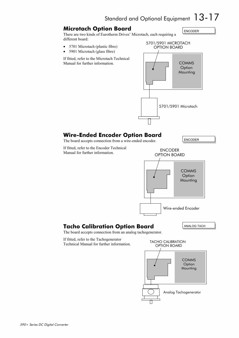
Standard and Optional Equipment 13-17
590+ Series DC Digital Converter
Microtach Option BoardThere are two kinds of Eurotherm Drives’ Microtach, each requiring adifferent board:
• 5701 Microtach (plastic fibre)• 5901 Microtach (glass fibre)
If fitted, refer to the Microtach TechnicalManual for further information.
Wire-Ended Encoder Option BoardThe board accepts connection from a wire-ended encoder.
If fitted, refer to the Encoder TechnicalManual for further information.
Tacho Calibration Option BoardThe board accepts connection from an analog tachogenerator.
If fitted, refer to the TachogeneratorTechnical Manual for further information.
ENCODER
5701/5901 Microtach
5701/5901 MICROTACHOPTION BOARD
COMMSOption
Mounting
ENCODER
Wire-ended Encoder
ENCODEROPTION BOARD
COMMSOption
Mounting
ANALOG TACH
Analog Tachogenerator
TACHO CALIBRATIONOPTION BOARD
COMMSOption
Mounting
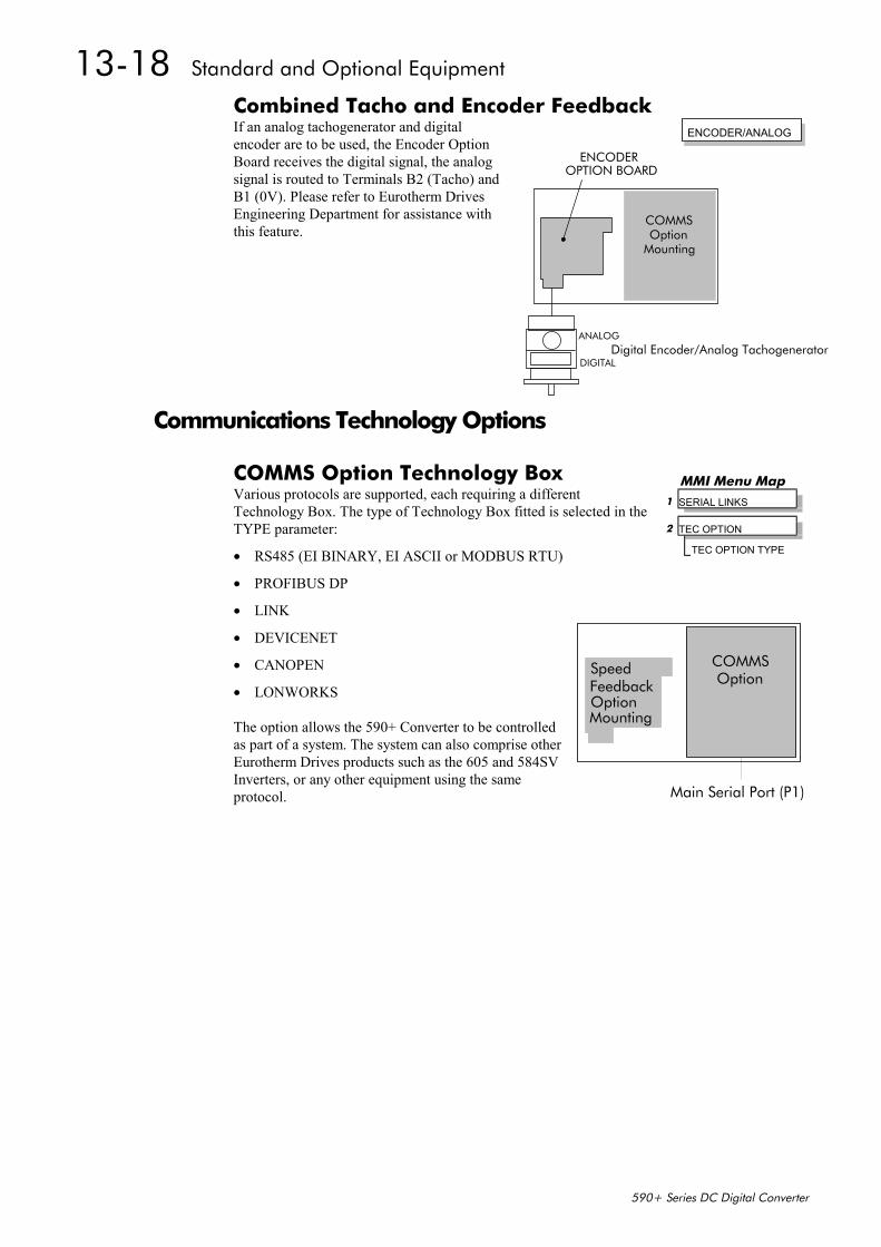
13-18 Standard and Optional Equipment
590+ Series DC Digital Converter
Combined Tacho and Encoder FeedbackIf an analog tachogenerator and digitalencoder are to be used, the Encoder OptionBoard receives the digital signal, the analogsignal is routed to Terminals B2 (Tacho) andB1 (0V). Please refer to Eurotherm DrivesEngineering Department for assistance withthis feature.
Communications Technology Options
COMMS Option Technology BoxVarious protocols are supported, each requiring a differentTechnology Box. The type of Technology Box fitted is selected in theTYPE parameter:
• RS485 (EI BINARY, EI ASCII or MODBUS RTU)
• PROFIBUS DP
• LINK
• DEVICENET
• CANOPEN
• LONWORKS
The option allows the 590+ Converter to be controlledas part of a system. The system can also comprise otherEurotherm Drives products such as the 605 and 584SVInverters, or any other equipment using the sameprotocol.
Digital Encoder/Analog TachogeneratorANALOG
DIGITAL
ENCODEROPTION BOARD
COMMSOption
Mounting
ENCODER/ANALOG
MMI Menu Map 1 SERIAL LINKS
2 TEC OPTION
TEC OPTION TYPE
COMMSOption
Mounting
SpeedFeedbackOption
Main Serial Port (P1)
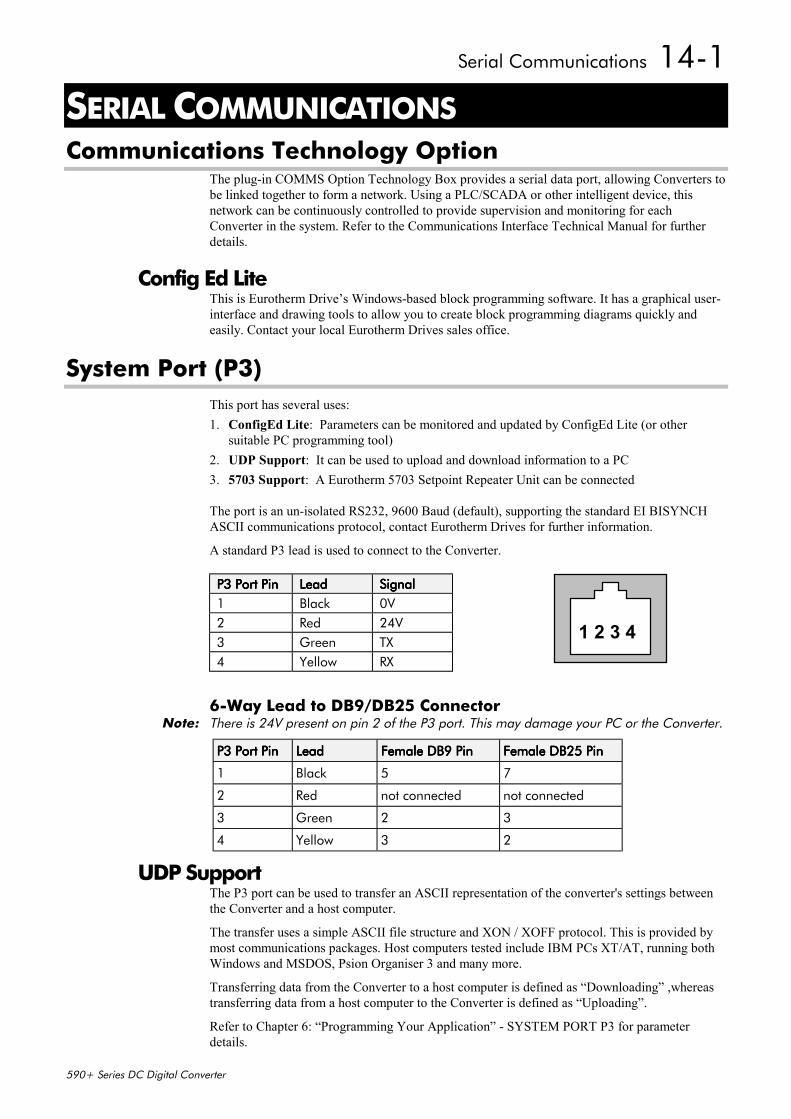
Serial Communications 14-1
590+ Series DC Digital Converter
14 SERIAL COMMUNICATIONSCommunications Technology Option
The plug-in COMMS Option Technology Box provides a serial data port, allowing Converters tobe linked together to form a network. Using a PLC/SCADA or other intelligent device, thisnetwork can be continuously controlled to provide supervision and monitoring for eachConverter in the system. Refer to the Communications Interface Technical Manual for furtherdetails.
Config Ed LiteThis is Eurotherm Drive’s Windows-based block programming software. It has a graphical user-interface and drawing tools to allow you to create block programming diagrams quickly andeasily. Contact your local Eurotherm Drives sales office.
System Port (P3)This port has several uses:1. ConfigEd Lite: Parameters can be monitored and updated by ConfigEd Lite (or other
suitable PC programming tool)2. UDP Support: It can be used to upload and download information to a PC3. 5703 Support: A Eurotherm 5703 Setpoint Repeater Unit can be connected
The port is an un-isolated RS232, 9600 Baud (default), supporting the standard EI BISYNCHASCII communications protocol, contact Eurotherm Drives for further information.
A standard P3 lead is used to connect to the Converter.
P3 Port PinP3 Port PinP3 Port PinP3 Port Pin LeadLeadLeadLead SignalSignalSignalSignal1 Black 0V2 Red 24V3 Green TX4 Yellow RX
6-Way Lead to DB9/DB25 ConnectorNote: There is 24V present on pin 2 of the P3 port. This may damage your PC or the Converter.
P3 Port PinP3 Port PinP3 Port PinP3 Port Pin LeadLeadLeadLead Female DB9 PinFemale DB9 PinFemale DB9 PinFemale DB9 Pin Female DB25 PinFemale DB25 PinFemale DB25 PinFemale DB25 Pin
1 Black 5 7
2 Red not connected not connected
3 Green 2 3
4 Yellow 3 2
UDP SupportThe P3 port can be used to transfer an ASCII representation of the converter's settings betweenthe Converter and a host computer.
The transfer uses a simple ASCII file structure and XON / XOFF protocol. This is provided bymost communications packages. Host computers tested include IBM PCs XT/AT, running bothWindows and MSDOS, Psion Organiser 3 and many more.
Transferring data from the Converter to a host computer is defined as “Downloading” ,whereastransferring data from a host computer to the Converter is defined as “Uploading”.
Refer to Chapter 6: “Programming Your Application” - SYSTEM PORT P3 for parameterdetails.
1 2 3 4
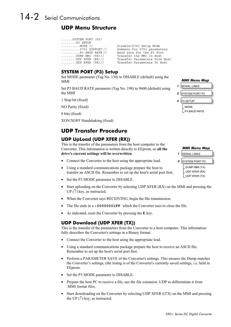
14-2 Serial Communications
590+ Series DC Digital Converter
UDP Menu Structure
......SYSTEM PORT (P3)
........P3 SETUP
..........MODE // Disable/5703 Setup Mode
..........5703 SUPPORT // Submenu for 5703 parameters
..........P3 BAUD RATE // Baud rate for the P3 Port
........DUMP MMI (TX)// Transfer the MMI to Host
........UDP XFER (RX)// Transfer Parameters From Host
........UDP XFER (TX)// Transfer Parameters To Host
SYSTEM PORT (P3) SetupSet MODE parameter (Tag No. 130) to DISABLE (default) using theMMI
Set P3 BAUD RATE parameter (Tag No. 198) to 9600 (default) usingthe MMI
1 Stop bit (fixed)
NO Parity (fixed)
8 bits (fixed)
XON/XOFF Handshaking (fixed)
UDP Transfer ProcedureUDP UpLoad (UDP XFER (RX))This is the transfer of the parameters from the host computer to theConverter. This information is written directly to EEprom, so all thedrive's current settings will be overwritten.
• Connect the Converter to the host using the appropriate lead.
• Using a standard communications package prepare the host totransfer an ASCII file. Remember to set up the host's serial port first.
• Set the P3 MODE parameter to DISABLE.
• Start uploading on the Converter by selecting UDP XFER (RX) on the MMI and pressing theUP (↑) key, as instructed.
• When the Converter says RECEIVING, begin the file transmission.
• The file ends in a :00000001FF which the Converter uses to close the file.
• As indicated, reset the Converter by pressing the E key.
UDP Download (UDP XFER (TX))This is the transfer of the parameters from the Converter to a host computer. This informationfully describes the Converter's settings in a Binary format.
• Connect the Converter to the host using the appropriate lead.
• Using a standard communications package prepare the host to receive an ASCII file.Remember to set up the host's serial port first.
• Perform a PARAMETER SAVE of the Converter's settings. This ensures the Dump matchesthe Converter’s settings, (the listing is of the Converter's currently saved settings, i.e. held inEEprom.
• Set the P3 MODE parameter to DISABLE.
• Prepare the host PC to receive a file; use the file extension .UDP to differentiate it from.MMI format files.
• Start downloading on the Converter by selecting UDP XFER ((TX) on the MMI and pressingthe UP (↑) key, as instructed.
MMI Menu Map
1 SERIAL LINKS
2 SYSTEM PORT P3
3 P3 SETUP
MODEP3 BAUD RATE
MMI Menu Map
1 SERIAL LINKS
2 SYSTEM PORT P3
DUMP MMI (TX)UDP XFER (RX)UDP XFER (TX)
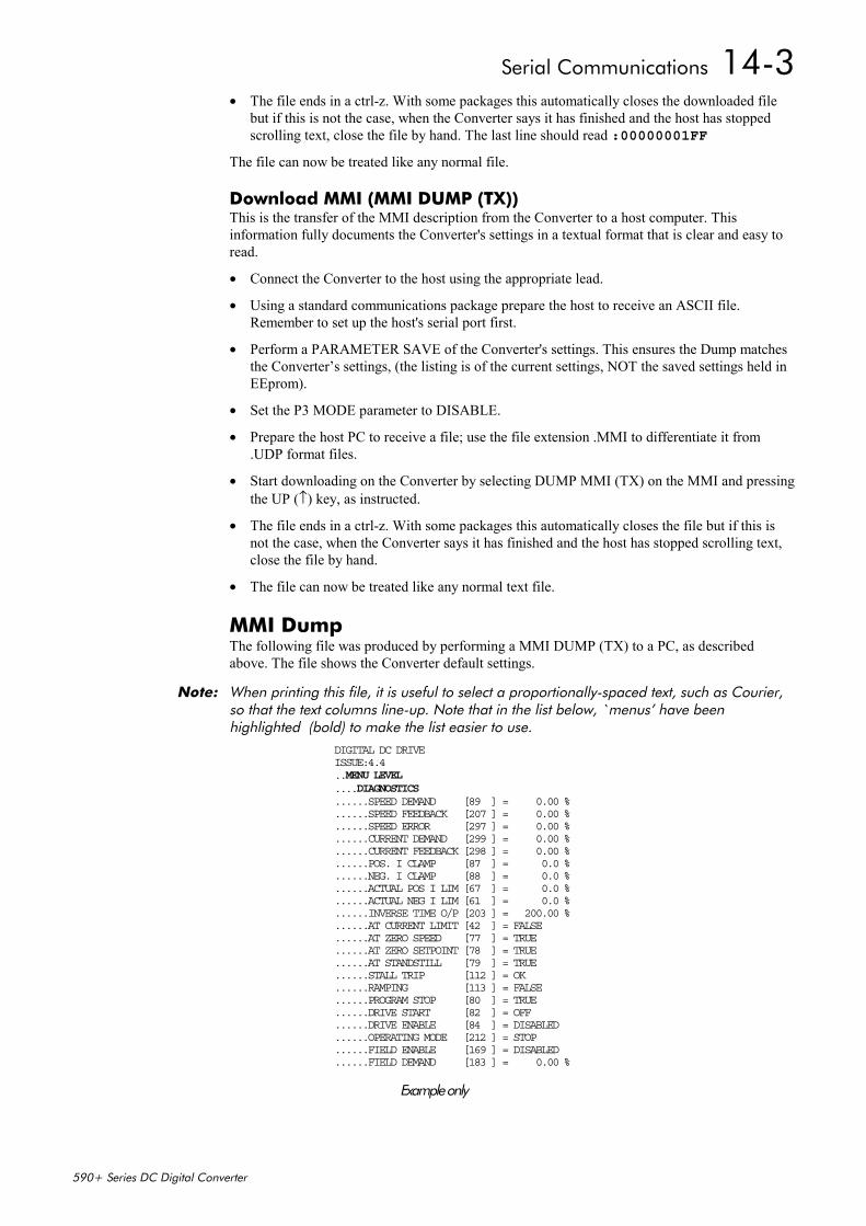
Serial Communications 14-3
590+ Series DC Digital Converter
• The file ends in a ctrl-z. With some packages this automatically closes the downloaded filebut if this is not the case, when the Converter says it has finished and the host has stoppedscrolling text, close the file by hand. The last line should read :00000001FF
The file can now be treated like any normal file.
Download MMI (MMI DUMP (TX))This is the transfer of the MMI description from the Converter to a host computer. Thisinformation fully documents the Converter's settings in a textual format that is clear and easy toread.
• Connect the Converter to the host using the appropriate lead.
• Using a standard communications package prepare the host to receive an ASCII file.Remember to set up the host's serial port first.
• Perform a PARAMETER SAVE of the Converter's settings. This ensures the Dump matchesthe Converter’s settings, (the listing is of the current settings, NOT the saved settings held inEEprom).
• Set the P3 MODE parameter to DISABLE.
• Prepare the host PC to receive a file; use the file extension .MMI to differentiate it from.UDP format files.
• Start downloading on the Converter by selecting DUMP MMI (TX) on the MMI and pressingthe UP (↑) key, as instructed.
• The file ends in a ctrl-z. With some packages this automatically closes the file but if this isnot the case, when the Converter says it has finished and the host has stopped scrolling text,close the file by hand.
• The file can now be treated like any normal text file.
MMI DumpThe following file was produced by performing a MMI DUMP (TX) to a PC, as describedabove. The file shows the Converter default settings.
Note: When printing this file, it is useful to select a proportionally-spaced text, such as Courier,so that the text columns line-up. Note that in the list below, `menus’ have beenhighlighted (bold) to make the list easier to use.
DIGITAL DC DRIVEISSUE:4.4..MENU LEVEL....DIAGNOSTICS......SPEED DEMAND [89 ] = 0.00 %......SPEED FEEDBACK [207 ] = 0.00 %......SPEED ERROR [297 ] = 0.00 %......CURRENT DEMAND [299 ] = 0.00 %......CURRENT FEEDBACK [298 ] = 0.00 %......POS. I CLAMP [87 ] = 0.0 %......NEG. I CLAMP [88 ] = 0.0 %......ACTUAL POS I LIM [67 ] = 0.0 %......ACTUAL NEG I LIM [61 ] = 0.0 %......INVERSE TIME O/P [203 ] = 200.00 %......AT CURRENT LIMIT [42 ] = FALSE......AT ZERO SPEED [77 ] = TRUE......AT ZERO SETPOINT [78 ] = TRUE......AT STANDSTILL [79 ] = TRUE......STALL TRIP [112 ] = OK......RAMPING [113 ] = FALSE......PROGRAM STOP [80 ] = TRUE......DRIVE START [82 ] = OFF......DRIVE ENABLE [84 ] = DISABLED......OPERATING MODE [212 ] = STOP......FIELD ENABLE [169 ] = DISABLED......FIELD DEMAND [183 ] = 0.00 %
Example only
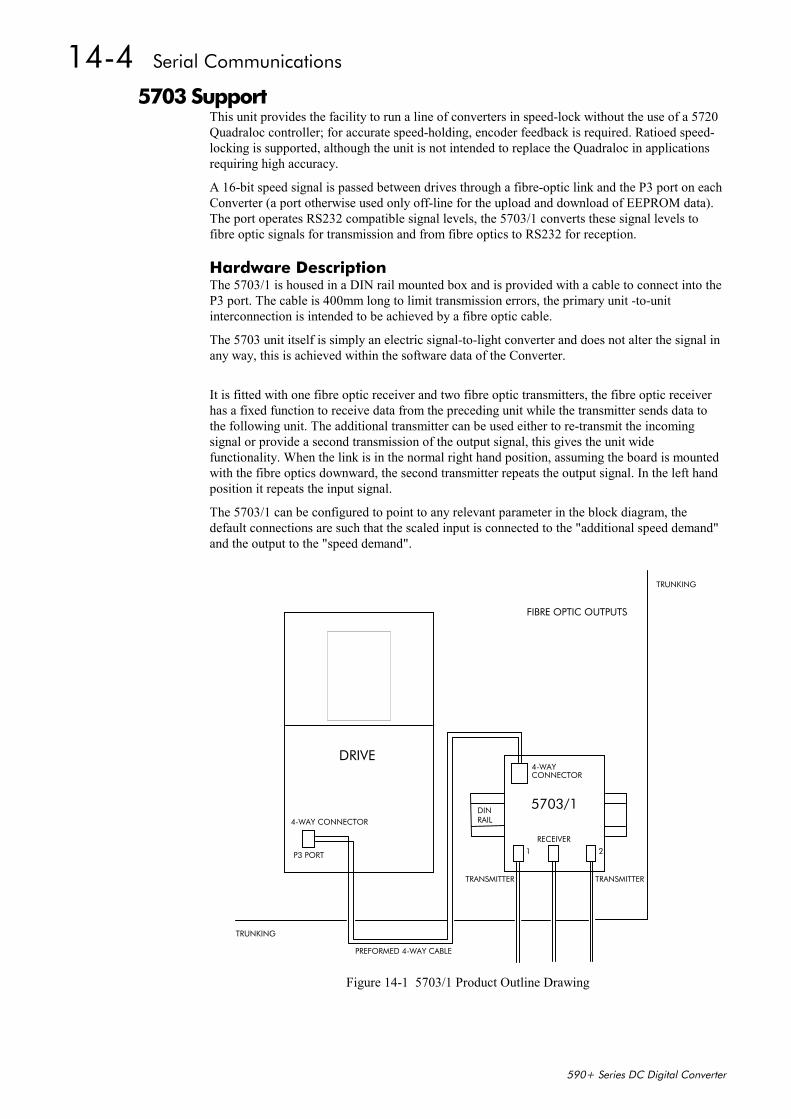
14-4 Serial Communications
590+ Series DC Digital Converter
5703 SupportThis unit provides the facility to run a line of converters in speed-lock without the use of a 5720Quadraloc controller; for accurate speed-holding, encoder feedback is required. Ratioed speed-locking is supported, although the unit is not intended to replace the Quadraloc in applicationsrequiring high accuracy.
A 16-bit speed signal is passed between drives through a fibre-optic link and the P3 port on eachConverter (a port otherwise used only off-line for the upload and download of EEPROM data).The port operates RS232 compatible signal levels, the 5703/1 converts these signal levels tofibre optic signals for transmission and from fibre optics to RS232 for reception.
Hardware DescriptionThe 5703/1 is housed in a DIN rail mounted box and is provided with a cable to connect into theP3 port. The cable is 400mm long to limit transmission errors, the primary unit -to-unitinterconnection is intended to be achieved by a fibre optic cable.
The 5703 unit itself is simply an electric signal-to-light converter and does not alter the signal inany way, this is achieved within the software data of the Converter.
It is fitted with one fibre optic receiver and two fibre optic transmitters, the fibre optic receiverhas a fixed function to receive data from the preceding unit while the transmitter sends data tothe following unit. The additional transmitter can be used either to re-transmit the incomingsignal or provide a second transmission of the output signal, this gives the unit widefunctionality. When the link is in the normal right hand position, assuming the board is mountedwith the fibre optics downward, the second transmitter repeats the output signal. In the left handposition it repeats the input signal.
The 5703/1 can be configured to point to any relevant parameter in the block diagram, thedefault connections are such that the scaled input is connected to the "additional speed demand"and the output to the "speed demand".
DRIVE
5703/1
FIBRE OPTIC OUTPUTS
TRUNKING
4-WAYCONNECTOR
TRANSMITTER
RECEIVER
TRANSMITTER
DINRAIL
1 2
4-WAY CONNECTOR
P3 PORT
TRUNKING
PREFORMED 4-WAY CABLE
Figure 14-1 5703/1 Product Outline Drawing
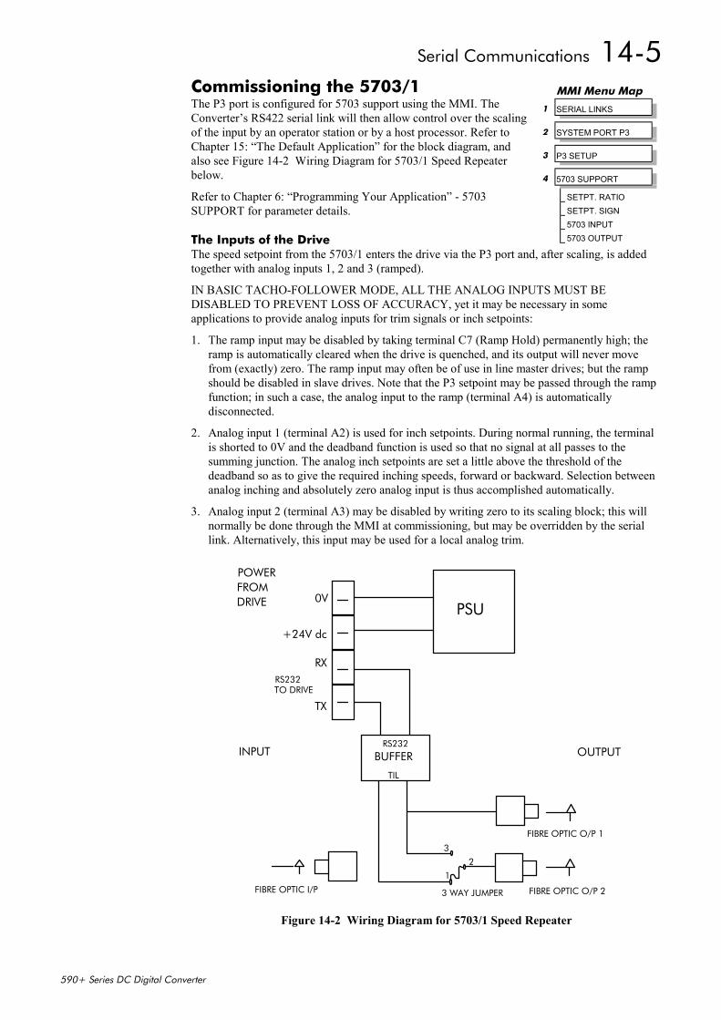
Serial Communications 14-5
590+ Series DC Digital Converter
Commissioning the 5703/1The P3 port is configured for 5703 support using the MMI. TheConverter’s RS422 serial link will then allow control over the scalingof the input by an operator station or by a host processor. Refer toChapter 15: “The Default Application” for the block diagram, andalso see Figure 14-2 Wiring Diagram for 5703/1 Speed Repeaterbelow.
Refer to Chapter 6: “Programming Your Application” - 5703SUPPORT for parameter details.
The Inputs of the DriveThe speed setpoint from the 5703/1 enters the drive via the P3 port and, after scaling, is addedtogether with analog inputs 1, 2 and 3 (ramped).
IN BASIC TACHO-FOLLOWER MODE, ALL THE ANALOG INPUTS MUST BEDISABLED TO PREVENT LOSS OF ACCURACY, yet it may be necessary in someapplications to provide analog inputs for trim signals or inch setpoints:
1. The ramp input may be disabled by taking terminal C7 (Ramp Hold) permanently high; theramp is automatically cleared when the drive is quenched, and its output will never movefrom (exactly) zero. The ramp input may often be of use in line master drives; but the rampshould be disabled in slave drives. Note that the P3 setpoint may be passed through the rampfunction; in such a case, the analog input to the ramp (terminal A4) is automaticallydisconnected.
2. Analog input 1 (terminal A2) is used for inch setpoints. During normal running, the terminalis shorted to 0V and the deadband function is used so that no signal at all passes to thesumming junction. The analog inch setpoints are set a little above the threshold of thedeadband so as to give the required inching speeds, forward or backward. Selection betweenanalog inching and absolutely zero analog input is thus accomplished automatically.
3. Analog input 2 (terminal A3) may be disabled by writing zero to its scaling block; this willnormally be done through the MMI at commissioning, but may be overridden by the seriallink. Alternatively, this input may be used for a local analog trim.
PSU
TX
RX
+24V dc
0V
POWERFROM
RS232
BUFFER
TIL
RS232TO DRIVE
INPUT
FIBRE OPTIC I/P
3
1
3 WAY JUMPER
2
FIBRE OPTIC O/P 2
FIBRE OPTIC O/P 1
OUTPUT
DRIVE
Figure 14-2 Wiring Diagram for 5703/1 Speed Repeater
MMI Menu Map
1 SERIAL LINKS
2 SYSTEM PORT P3
3 P3 SETUP
4 5703 SUPPORT
SETPT. RATIOSETPT. SIGN5703 INPUT5703 OUTPUT
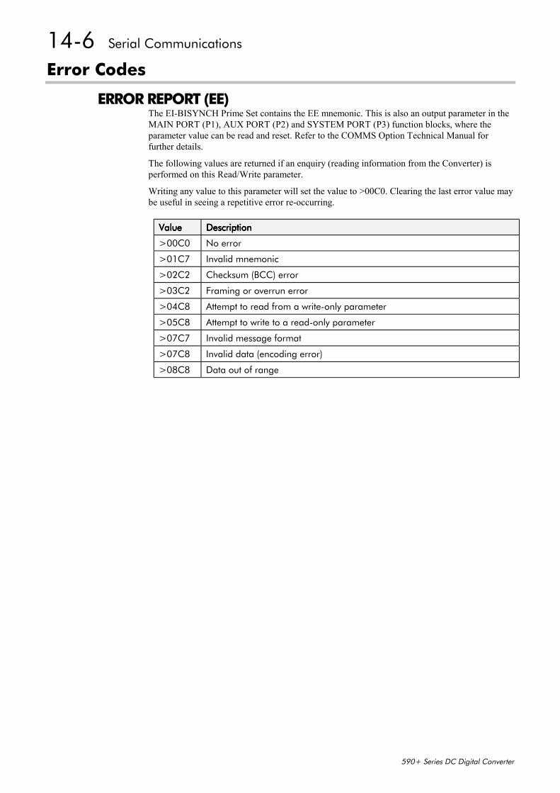
14-6 Serial Communications
590+ Series DC Digital Converter
Error Codes
ERROR REPORT (EE)The EI-BISYNCH Prime Set contains the EE mnemonic. This is also an output parameter in theMAIN PORT (P1), AUX PORT (P2) and SYSTEM PORT (P3) function blocks, where theparameter value can be read and reset. Refer to the COMMS Option Technical Manual forfurther details.
The following values are returned if an enquiry (reading information from the Converter) isperformed on this Read/Write parameter.
Writing any value to this parameter will set the value to >00C0. Clearing the last error value maybe useful in seeing a repetitive error re-occurring.
ValueValueValueValue DescriptionDescriptionDescriptionDescription
>00C0 No error
>01C7 Invalid mnemonic
>02C2 Checksum (BCC) error
>03C2 Framing or overrun error
>04C8 Attempt to read from a write-only parameter
>05C8 Attempt to write to a read-only parameter
>07C7 Invalid message format
>07C8 Invalid data (encoding error)
>08C8 Data out of range

The Default Application 15-1
590+ Series DC Digital Converter
15 THE DEFAULT APPLICATION
Block DiagramsThe Converter is supplied with a pre-programmed set of parameters providing for basic speedcontrol. The following block diagrams show this factory set-up.
If you make any permanent changes to the block diagram, remember to update the non-volatilememory within the Converter by performing a PARAMETER SAVE. Refer to Chapter 5: “TheOperator Station” - Saving Your Application.
To return to the default application, refer to Chapter 5: “The Operator Station” - Menu Shortcutsand Special Key Combinations.

15-2 The Default Application
590+ Series DC Digital Converter
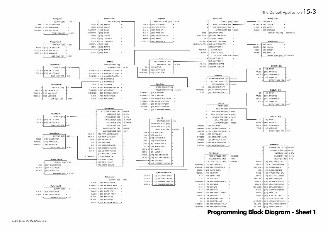
The Default Application 15-3
590+ Series DC Digital Converter
Analog Ouput 1
62 – [251] INPUT –100.00 % – [245] 10V CAL –
0.00 % – [464] OFFSET –
FALSE – [362] MODULUS –– ANOUT 1 (A7) [ 55] – 0.00 VOLTS
Analog Output 2
63 – [252] INPUT –100.00% – [248] 10V CAL –
0.00% – [465] OFFSET –FALSE – [363] MODULUS –
– ANOUT 2 (A8) [ 56] – 0.00 VOLTS
Aux I/O
START (C3) [ 68] – ON
DIGITAL INPUT C4 [ 69] – OFF
DIGITAL INPUT C5 [ 70] – OFF
SEQ STATUS [537] – 0x0000
ON – [161] AUX START –
ON – [227] AUX JOG –ON – [168] AUX ENABLE –
OFF – [ 94] AUX DIGOUT 1 –OFF – [ 95] AUX DIGOUT 2 –OFF – [ 96] AUX DIGOUT 3 –
0.00 % – [128] ANOUT 1 –0.00 % – [129] ANOUT 2 –0x0000 – [536] REM. SEQUENCE –FALSE – [535] REM. SEQ. ENABLE –
OFF – [496] JOG/SLACK –OFF – [497] CURRENT CONTROL –
Calibration
– TERMINAL VOLTS [ 57] – 0.00%
– TACH INPUT (B2) [ 58] – 0.0%
– ENCODER [ 59] – 0 RPM
– BACK EMF [ 60] – 0.00%
– FIELD FBK. [181] – 0.0%
1.0000 – [ 20] ARMATURE V CAL. –0.00 % – [ 21] IR COMPENSATION –
1000 RPM – [ 22] ENCODER RPM –
1000 – [ 24] ENCODER LINES –1.0000 – [ 23] ANALOG TACH CAL –0.00 % – [ 10] ZERO SPD. OFFSET –
BIPOLAR – [ 25] ARMATURE I (A9) –50.00 % – [180] SPDFBK ALM LEVEL –95.00 % – [263] STALL THRESHOLD –
10.0 SECS – [224] STALL TRIP DELAY –125.00% – [188] OVERSPEED LEVEL –
1.0000 – [182] FIELD I CAL –0x0000 – [267] POSITION COUNT –
1 – [275] POSITION DIVIDER –100 VOLTS – [521] NOM MOTOR VOLTS –
2.0 AMPS – [523] ARMATURE CURRENT –
0.2 AMPS – [524] FIELD CURRENT –
Current Loop
– AT CURRENT LIMIT [ 42] – FALSE
– IA DEMAND [66] – 0.00%
– IA FEEDBACK [65] – 0.00%
– IA FEEDBACK [538] – 0.0 AMPS
– IF FEEDBACK [539] – 0.0 AMPS
– AUTOTUNE [ 18] – OFF
– ILOOP SUSPEND [ 46] – FALSE
– MASTER BRIDGE [527] – OFF
100.00 % – [ 15] CUR. LIMIT/SCALER –
200.00 % – [421] MAIN CURR. LIMIT –45.00 – [ 16] PROP GAIN –3.50 – [ 17] INT. GAIN –2.00 – [136] FEED FORWARD –
12.00 % – [137] DISCONTINUOUS –
0.00 % – [ 30] ADDITIONAL DEM –DISABLED – [ 90] BIPOLAR CLAMPS –
4Q (REGEN) – [201] REGEN MODE –
100.00 % – [301] POS. I CLAMP –-100.00 % – [ 48] NEG. I CLAMP –
DISABLED – [119] I DMD. ISOLATE –
CURRENT PROFILE
100.0 % – [ 32] SPD BRK 1 (LOW) –
100.0 % – [ 31] SPD BRK 2 (HIGH) –200.0 % – [ 93] IMAX BRK 1 (SPD1) –200.0 % – [ 33] IMAX BRK 2 (SPD2) –
Digital Input 1
– OUTPUT [102] – 90
0.01 % – [103] VALUE TRUE –0.00 % – [104] VALUE FALSE –
– DIGIN 1 (C6) [ 71] – OFF
Digital Input 2
– OUTPUT [105] – 118
0.01 % – [106] VALUE TRUE –0.00 % – [107] VALUE FALSE –
– DIGIN 2 (C7) [ 72] – OFF
Digital Input 3
– OUTPUT [108] – 119
0.01 % – [109] VALUE TRUE –0.00 % – [110] VALUE FALSE –
– DIGIN 3 (C8) [ 73] – OFF
DIGOUT 1 (B5)
77 – [ 97] INPUT –
FALSE – [359] INVERTED –0.00 % – [195] THRESHOLD –TRUE – [ 43] MODULUS –
– DIGOUT 1 (B5) [ 74] – OFF
DIGOUT 2 (B6)
122 – [ 98] INPUT –FALSE – [360] INVERTED –0.00 % – [196] THRESHOLD –
TRUE – [ 44] MODULUS –– DIGOUT 2 (B6) [ 75] – OFF
DIGOUT 3 (B7)
125 – [ 99] INPUT –
FALSE – [361] INVERTED –0.00 % – [197] THRESHOLD –TRUE – [ 45] MODULUS –
– DIGOUT 3 (B7) [ 76] – OFF
Field Control
– FIELD ENABLED [169] – DISABLED
– FIELD DEMAND [183] – 0.00%
– FLD. FIRING ANGLE [184] – 0.00 DEG
ENABLED – [170] FIELD ENABLE –VOLTAGE – [209] FLD CTRL MODE IS –
90.00% – [210] RATIO OUT/IN –100.00% – [171] SETPOINT –
0.10 – [173] PROP. GAIN –1.28 – [172] INT. GAIN –
DISABLED – [174] FLD. WEAK ENABLE –
2.00 – [175] EMF LEAD –40.00 – [176] EMF LAG –
0.30 – [177] EMF GAIN –
10.00% – [179] MIN FIELD CURRENT –100.00% – [178] MAX VOLTS –
100 – [191] BEMF FBK LEAD –100 – [192] BEMF FBK LAG –
0.0 SECS – [185] FLD. QUENCH DELAY –
QUENCH – [186] FLD. QUENCH MODE –
Alarms
– READY [125] – FALSE
– HEALTHY [122] – TRUE
– HEALTH WORD [115] – 0x0000
– HEALTH STORE [116] – 0x0000
– REMOTE TRIP [542] – FALSE
– STALL TRIP [112] – OK
– LAST ALARM [528] – 0x0000
ENABLED – [ 19] FIELD FAIL –ENABLED – [111] 5703 RCV ERROR –
INHIBITED – [ 28] STALL TRIP INHIBIT –TRUE – [305] TRIP RESET –
ENABLED – [ 81] SPEED FBK ALARM –ENABLED – [ 92] ENCODER ALARM –ENABLED – [540] REM TRIP INHIBIT –
10.0 SECS – [541] REM TRIP DELAY –
Jog/Slack
– OPERATING MODE [212] – STOP
5.00 % – [218] JOG SPEED 1 –-5.00 % – [219] JOG SPEED 2 –
5.00 % – [253] TAKE UP 1 –-5.00 % – [254] TAKE UP 2 –10.00 % – [225] CRAWL SPEED –FALSE – [228] MODE –
1.0 SECS – [355] RAMP RATE –
Raise/Lower
– OUTPUT [264] – 0.00%
0.00 % – [255] RESET VALUE –
10.0 SECS – [256] INCREASE RATE –10.0 SECS – [257] DECREASE RATE –
FALSE – [261] RAISE INPUT –
FALSE – [262] LOWER INPUT –-100.00 % – [258] MIN VALUE –
100.00 % – [259] MAX VALUE –FALSE – [307] EXTERNAL RESET –
RAMPS
RAMP OUTPUT [ 85] – 0.00%
RAMPING [113] – FALSE
10.0 SECS – [ 2] RAMP ACCEL TIME –
10.0 SECS – [ 3] RAMP DECEL TIME –ENABLED – [ 4 CONSTANT ACCEL –
OFF – [118] RAMP HOLD –0.00 % – [ 5] RAMP INPUT –2.50 % – [266] % S-RAMP –
0.50 % – [286] RAMPING THRESH. –ENABLED – [287] AUTO RESET –DISABLED – [288] EXTERNAL RESET –
0.00 % – [422] RESET VALUE –0.00 % – [126] MIN. SPEED –
Setpoint Sum 1
– SPT. SUM [ 86] – 0.00%
1.0000 – [ 6] RATIO 1 –1.0000 – [208] RATIO 0 –
POSITIVE – [ 8] SIGN 1 –POSITIVE – [292] SIGN 0 –
1.0000 – [419] DIVIDER 1 –1.0000 – [420] DIVIDER 0 –
0.00 % – [131] DEADBAND –105.00 % – [375] LIMIT –
0.00 % – [423] INPUT 2 –0.00 % – [100] INPUT 1 –0.00 % – [309] INPUT 0 –
Speed Loop
– OUTPUT [356] –0.00%
– SPEED FEEDBACK [ 62] –0.00%
– SPEED SETPOINT [ 63] –0.00%
– SPEED ERROR [ 64] –0.00%
10.00 – [ 14] PROP. GAIN –0.500 SECS – [ 13] INT. TIME CONST. –
OFF – [202] INT. DEFEAT –POSITIVE – [ 49] ENCODER SIGN –
ARM VOLTS FBK – [ 47] SPEED FBK SEL –0.00% – [289] SETPOINT 1 –
POSITIVE – [ 9] SIGN 2 (A3) –1.0000 – [ 7] RATIO 2 (A3) –
– SETPOINT 2 (A3) [290] –0.00%
0.00% – [291] SETPOINT 3 –0.00% – [ 41] SETPOINT 4 –
105.00% – [357] MAX DEMAND –-105.00% – [358] MIN DEMAND –
Standstill
– AT ZERO SETPOINT [ 78] – FALSE
– AT ZERO SPEED [ 77] – FALSE
– AT STANDSTILL [ 79] – FALSE
89 – [306] ZERO SETPOINT –DISABLED – [ 11] STANDSTILL LOGIC –
2.00% – [ 12] ZERO THRESHOLD –
Stop Rates
– SPEED DEMAND [ 89] – 0.00%
– PROGRAM STOP [ 80] – FALSE
10.0 SECS – [ 27] STOP TIME –60.0 SECS – [217] STOP LIMIT –
1.0 SECS – [302] CONTACTOR DELAY –0.1 SECS – [ 26] PROG STOP TIME –
60.0 SECS – [216] PROG STOP LIMIT –100.00 % – [ 91] PROG STOP I LIM –
2.00 % – [ 29] STOP ZERO SPEED –
5703
– SCALED INPUT [189] – 0.00%
– RAW INPUT [187] – 0.00%
89 – [134] OUTPUT –
0.0000 – [132] SETPT. RATIO –POSITIVE – [133] SETPT. SIGN –
Analog Input 1
– OUTPUT [246] – 100
1.0000 – [230] CALIBRATION –100.00 % – [231] MAX VALUE –
-100.00 % – [232] MIN VALUE –– ANIN 1 (A2) [ 50] – 0.00V
-100.00 %
Analog Input 3
– OUTPUT [249] – 5
1.0000 – [236] CALIBRATION –100.00 % – [237] MAX VALUE –
– [238] MIN VALUE –– ANIN 3 (A4) [ 52] – 0.00V
Analog Input 2
– OUTPUT [493] – 0.00%
1.0000 – [233] CALIBRATION –100.00 % – [234] MAX VALUE –
-100.00 % – [235] MIN VALUE –
– ANIN 2 (A3) [ 51] – 0.00V
100.00 %
-100.00 %
Analog Input 4
– OUTPUT [250] – 48
1.0000 – [239] CALIBRATION –– [240] MAX VALUE –
– [238] MIN VALUE –– ANIN 4 (A5) [ 53] – 0.00V
Analog Input 5
– OUTPUT [247] – 301
1.0000 – [242] CALIBRATION –100.00 % – [243] MAX VALUE –
-100.00 % – [244] MIN VALUE –– ANIN 5 (A6) [ 54] – 0.00V
Programming Block Diagram - Sheet 1
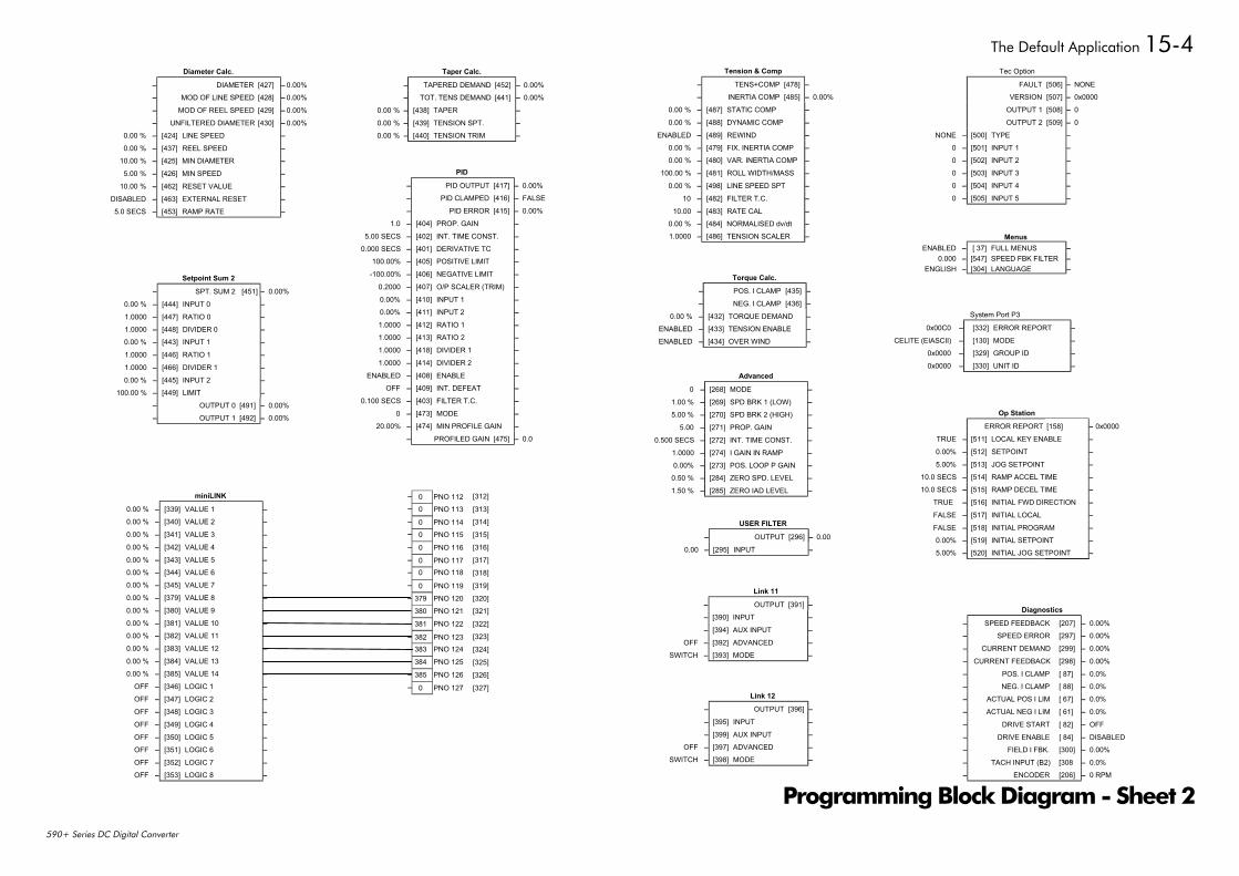
The Default Application 15-4
590+ Series DC Digital Converter
Diagnostics
– SPEED FEEDBACK [207] – 0.00%
– SPEED ERROR [297] – 0.00%
– CURRENT DEMAND [299] – 0.00%
– CURRENT FEEDBACK [298] – 0.00%
– POS. I CLAMP [ 87] – 0.0%
– NEG. I CLAMP [ 88] – 0.0%
– ACTUAL POS I LIM [ 67] – 0.0%
– ACTUAL NEG I LIM [ 61] – 0.0%
– DRIVE START [ 82] – OFF
– DRIVE ENABLE [ 84] – DISABLED
– FIELD I FBK. [300] – 0.00%
– TACH INPUT (B2) [308 – 0.0%
– ENCODER [206] – 0 RPM
Diameter Calc.
– DIAMETER [427] – 0.00%
– MOD OF LINE SPEED [428] – 0.00%
– MOD OF REEL SPEED [429] – 0.00%
– UNFILTERED DIAMETER [430] – 0.00%
0.00 % – [424] LINE SPEED –0.00 % – [437] REEL SPEED –
10.00 % – [425] MIN DIAMETER –5.00 % – [426] MIN SPEED –
10.00 % – [462] RESET VALUE –DISABLED – [463] EXTERNAL RESET –5.0 SECS – [453] RAMP RATE –
Link 11
– OUTPUT [391] – 0
0 – [390] INPUT –0 – [394] AUX INPUT –
OFF – [392] ADVANCED –SWITCH – [393] MODE –
Link 12
– OUTPUT [396] – 0
0 – [395] INPUT –0 – [399] AUX INPUT –
OFF – [397] ADVANCED –SWITCH – [398] MODE –
miniLINK
0.00 % – [339] VALUE 1 –0.00 % – [340] VALUE 2 –0.00 % – [341] VALUE 3 –0.00 % – [342] VALUE 4 –0.00 % – [343] VALUE 5 –0.00 % – [344] VALUE 6 –0.00 % – [345] VALUE 7 –0.00 % – [379] VALUE 8 –0.00 % – [380] VALUE 9 –0.00 % – [381] VALUE 10 –0.00 % – [382] VALUE 11 –0.00 % – [383] VALUE 12 –0.00 % – [384] VALUE 13 –0.00 % – [385] VALUE 14 –
OFF – [346] LOGIC 1 –OFF – [347] LOGIC 2 –OFF – [348] LOGIC 3 –OFF – [349] LOGIC 4 –OFF – [350] LOGIC 5 –OFF – [351] LOGIC 6 –OFF – [352] LOGIC 7 –OFF – [353] LOGIC 8 –
Op Station
ERROR REPORT [158] – 0x0000
TRUE – [511] LOCAL KEY ENABLE –0.00% – [512] SETPOINT –5.00% – [513] JOG SETPOINT –
10.0 SECS – [514] RAMP ACCEL TIME –10.0 SECS – [515] RAMP DECEL TIME –
TRUE – [516] INITIAL FWD DIRECTION –FALSE – [517] INITIAL LOCAL –FALSE – [518] INITIAL PROGRAM –0.00% – [519] INITIAL SETPOINT –5.00% – [520] INITIAL JOG SETPOINT –
PID
– PID OUTPUT [417] – 0.00%
– PID CLAMPED [416] – FALSE
– PID ERROR [415] – 0.00%
1.0 – [404] PROP. GAIN –5.00 SECS – [402] INT. TIME CONST. –
0.000 SECS – [401] DERIVATIVE TC –100.00% – [405] POSITIVE LIMIT –
-100.00% – [406] NEGATIVE LIMIT –0.2000 – [407] O/P SCALER (TRIM) –0.00% – [410] INPUT 1 –0.00% – [411] INPUT 2 –1.0000 – [412] RATIO 1 –1.0000 – [413] RATIO 2 –1.0000 – [418] DIVIDER 1 –1.0000 – [414] DIVIDER 2 –
ENABLED – [408] ENABLE –OFF – [409] INT. DEFEAT –
0.100 SECS – [403] FILTER T.C. –0 – [473] MODE –
20.00% – [474] MIN PROFILE GAIN –– PROFILED GAIN [475] – 0.0
Setpoint Sum 2
– SPT. SUM 2 [451] – 0.00%
0.00 % – [444] INPUT 0 –1.0000 – [447] RATIO 0 –1.0000 – [448] DIVIDER 0 –0.00 % – [443] INPUT 1 –1.0000 – [446] RATIO 1 –1.0000 – [466] DIVIDER 1 –0.00 % – [445] INPUT 2 –
100.00 % – [449] LIMIT –– OUTPUT 0 [491] – 0.00%
– OUTPUT 1 [492] – 0.00%
Advanced
0 – [268] MODE –1.00 % – [269] SPD BRK 1 (LOW) –5.00 % – [270] SPD BRK 2 (HIGH) –
5.00 – [271] PROP. GAIN –0.500 SECS – [272] INT. TIME CONST. –
1.0000 – [274] I GAIN IN RAMP –0.00% – [273] POS. LOOP P GAIN –0.50 % – [284] ZERO SPD. LEVEL –1.50 % – [285] ZERO IAD LEVEL –
System Port P3
0x00C0 – [332] ERROR REPORT –CELITE (EIASCII) – [130] MODE –
0x0000 – [329] GROUP ID –0x0000 – [330] UNIT ID –
Taper Calc.
– TAPERED DEMAND [452] – 0.00%
– TOT. TENS DEMAND [441] – 0.00%
0.00 % – [438] TAPER –0.00 % – [439] TENSION SPT. –0.00 % – [440] TENSION TRIM –
Tec Option
FAULT [506] – NONE
VERSION [507] – 0x0000
OUTPUT 1 [508] – 0
OUTPUT 2 [509] – 0
NONE – [500] TYPE –
0 – [501] INPUT 1 –0 – [502] INPUT 2 –0 – [503] INPUT 3 –0 – [504] INPUT 4 –0 – [505] INPUT 5 –
Tension & Comp
– TENS+COMP [478] – 0
– INERTIA COMP [485] – 0.00%
0.00 % – [487] STATIC COMP –0.00 % – [488] DYNAMIC COMP –
ENABLED – [489] REWIND –0.00 % – [479] FIX. INERTIA COMP –0.00 % – [480] VAR. INERTIA COMP –
100.00 % – [481] ROLL WIDTH/MASS –0.00 % – [498] LINE SPEED SPT –
10 – [482] FILTER T.C. –10.00 – [483] RATE CAL –
0.00 % – [484] NORMALISED dv/dt –1.0000 – [486] TENSION SCALER –
Torque Calc.
– POS. I CLAMP [435] – 0
– NEG. I CLAMP [436] – 0
0.00 % – [432] TORQUE DEMAND –ENABLED – [433] TENSION ENABLE –ENABLED – [434] OVER WIND –
USER FILTER
– OUTPUT [296] – 0.00
0.00 – [295] INPUT –
– 0 PNO 112– 0 PNO 113
– 0 PNO 114– 0 PNO 115– 0 PNO 116
– 0 PNO 117– 0 PNO 118
– 0 PNO 119– 379 PNO 120– 380 PNO 121– 381 PNO 122
– 382 PNO 123– 383 PNO 124– 384 PNO 125
– 385 PNO 126
– 0 PNO 127
[312]
[313]
[314]
[315]
[316]
[317]
[318]
[319]
[320]
[321]
[322]
[323]
[324]
[325]
[326]
[327]
MenusENABLED – [ 37] FULL MENUS –
0.000 – [547] SPEED FBK FILTER –ENGLISH – [304] LANGUAGE –
Programming Block Diagram - Sheet 2
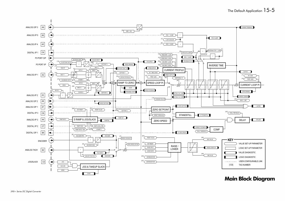
The Default Application 15-5
590+ Series DC Digital Converter
Main Block Diagram
Ia
Ia
ARM I (A9)
POS I CLAMP
I LIMIT (SCALER)
NEG I CLAMP
x
x
BIPOLAR CLAMPS
NEG I CLAMP
PROGRAM STOP
PROGRAM STOP I LIMIT-1
-1
INVERSE TIME
+-
CURRENT LOOP PI
OUTPUT
INT. GAIN
PROP. GAIN
CURRENT DEMAND
DRIVE ENABLE
MAIN I LIMIT
I LIMITED
ACTUAL -Ve I LIMIT
ACTUAL +Ve I LIMIT
++
ADDITIONAL I D
I DEMAND ISOLATE
SPEED LOOP PI
P3 OUTPUT
INT. TIME CONST.
PROP. GAIN
SPEED DEMAND
RAMP TO ZERO
CONTACTOR DELAY
SPEED ERROR
+-
SPEED FEEDBACK
STOP
PROGRAM STOP
SETPOINT SUM 1 O/P
SETPOINT 1
+ +
++++
++
-
+-
AB
AB
RATIO 0
DIVIDER 0
INPUT 0
RATIO 1
DIVIDER 1
+-x
INPUT 1
DEADBAND WIDTH
SETPOINT 2
+-
SCALED INPUT
INPUT 2
SETPOINT 4x
RAW I/P
P3 SETPOINT RATIO
CURRENT PROFILE
I MAX BRK 1 (LOW)
I MAX BRK 2 (HIGH)
SPEED BRK 1 (LOW)
SPEED BRK 2 (HIGH)
SPEED SETPOINT
SETPOINT 3EXT RESET RESET VALUE
RAMP INPUT S RAMP & JOG/SLACKRAMP O/P
RAMPING
RAMP HOLD RAMP ACCEL TIME
S RAMP %RAMP DECEL TIME
ZERO SETPOINT
ZERO SPEED
SPEED THRESHOLD STANDSTILL AT STANDSTILL
AT ZERO SPEED
AT ZERO SETPOINT
DELAY STALLED
STALL TRIP DELAY
COMP
RAISE/LOWER O/P
MAX VALUE
MIN VALUE
RAISE /LOWER
RAISE INPUT
LOWER INPUT
EXT RESET
RESET VALUE
INCREASE RATE
DECREASE RATE
ENCODER RPM
+x
ENCODER SIGN
ENCODER
x
ANALOG TACH CAL
TACH INPUT
BACK EMF
SPEED F/B SELECT
+-
ZERO SPEED OFFSET
A9
A6
A5
C6
A2
A3
A8
A7
C8
A4
C7
B5
B2
ANALOG O/P 3
ANALOG I/P 5
ANALOG I/P 4
DIGITAL I/P 1
P3 PORT O/P
P3 PORT I/P
ANALOG I/P 1
ANALOG I/P 2
ANALOG O/P 2
ANALOG O/P 1
DIGITAL I/P 3
ANALOG I/P 3
DIGITAL I/P 2
DIGITAL O/P 1
ENCODER
ANALOG TACH
CURRENT FEEDBACK
POS I CLAMP
-
CURRENT FEEDBACK
STALL THRESHOLD
C4JOG/SLACK JOG
AUX JOG JOG & TAKEUP SLACKMODE
START
[25]
[301]
[15]
[48]
[90][91]
[32]
[31]
[93]
[33]
[132][189] [41]
[423]
SIGN 1
SIGN 0
[8]
[292]
[6]
[419][208]
[131]
[100]
[187]
RATIO 2[7]
SIGN 2[9]
[309]
[420] [290]
[302]
[289] [13]
[14]
[30]
[17]
[16]
[421]
[302]
[119]
[12]
[291][422][288]
[5]
[118]
[3]
[2]
[266]
[22]
[49]
[23]
[47]
[10]
[255]
[307]
[261]
[262]
[256]
[257]
[259]
[258]
VALUE SET-UP PARAMETER
LOGIC SET-UP PARAMETER
VALUE DIAGNOSTIC
LOGIC DIAGNOSTIC
KEY
USER-CONFIGURABLE LINK[123] TAG NUMBER
[133]SETPOINT SIGN
SPEED LOOP O/P
549]
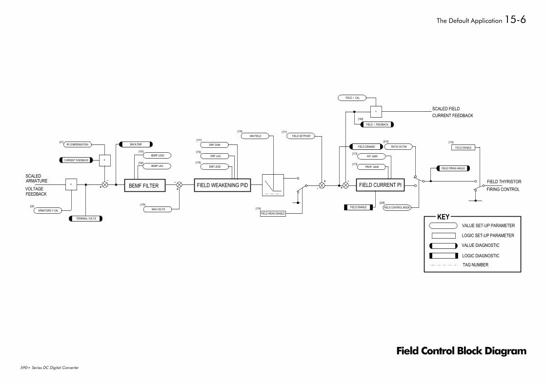
The Default Application 15-6
590+ Series DC Digital Converter
EMF LAG
EMF LEAD
VALUE SET-UP PARAMETER
LOGIC SET-UP PARAMETER
VALUE DIAGNOSTIC
LOGIC DIAGNOSTIC
KEY
FIELD WEAKENING PID+
-+
-BEMF FILTERx FIELD CURRENT PI
x
EMF GAIN
BEMF LEAD
BEMF LAG
INT. GAIN
PROP. GAIN
ARMATURE V CAL
IR COMPENSATION
x
MAX VOLTS
MIN FIELD FIELD SETPOINT
FIELD I CAL
RATIO OUT/IN
FIELD CONTROL MODE
FIELD I FEEDBACK
FIELD DEMANDBACK EMF
CURRENT FEEDBACK
TERMINAL VOLTS
FIELD ENABLE
+- +
-
FIELD WEAK ENABLE
FIELD ENABLE
SCALEDARMATUREVOLTAGEFEEDBACK
FIELD THYRISTORFIRING CONTROL
FIELD FIRING ANGLE
SCALED FIELDCURRENT FEEDBACK
[21]
[20]
[191]
[192]
[178]
[177]
[176]
[175]
[179] [171]
[174]
[182]
[210]
[172]
[173]
[209]
[170]
TAG NUMBER
Field Control Block Diagram
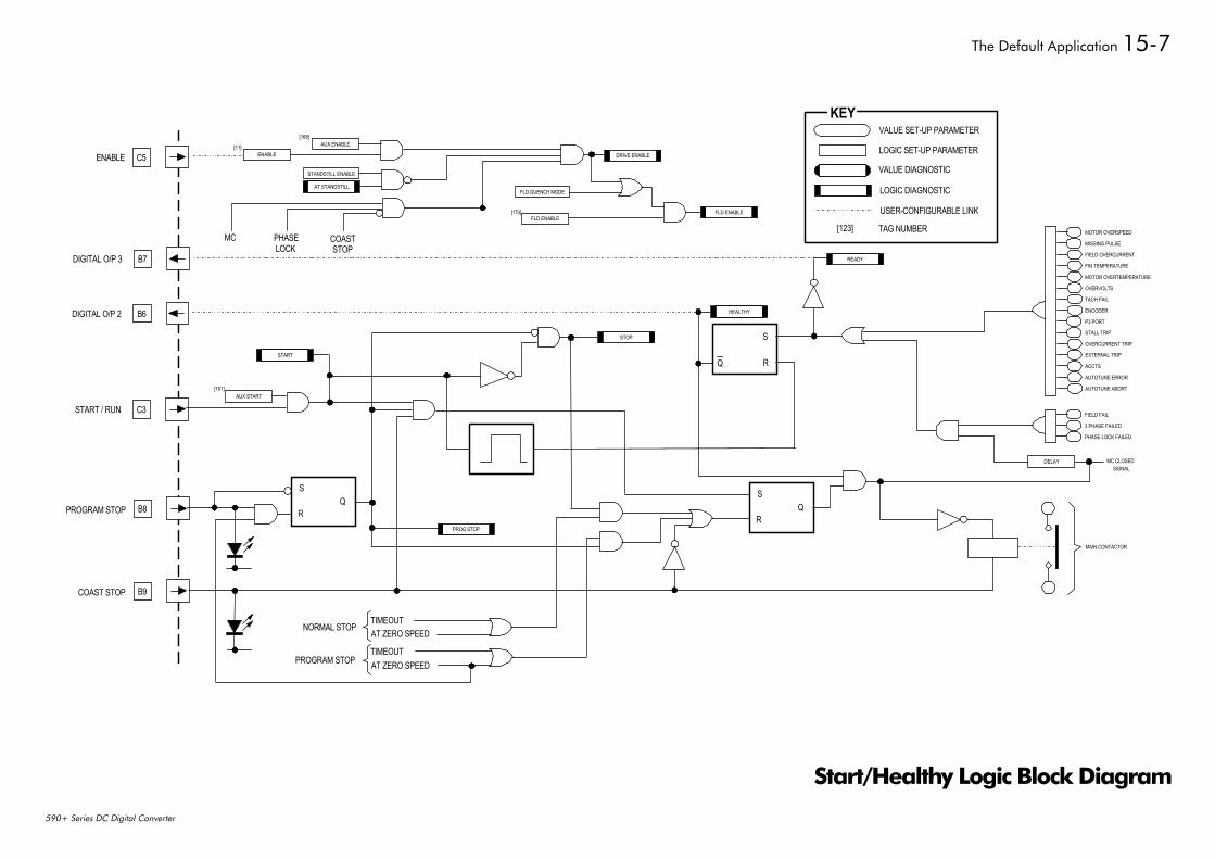
The Default Application 15-7
590+ Series DC Digital Converter
C5ENABLE
B7DIGITAL O/P 3
B6DIGITAL O/P 2
C3START / RUN
B8PROGRAM STOP
B9COAST STOP
S
RQ
S
RQ
S
RQ
READY
HEALTHY
STOP
FLD ENABLE
DRIVE ENABLE
AT STANDSTILL
PROG STOP
AUX ENABLE
STANDSTILL ENABLE
FLD ENABLE
AUX START
DELAY
MC PHASELOCK
COASTSTOP
TIMEOUTAT ZERO SPEED
TIMEOUTAT ZERO SPEED
NORMAL STOP
PROGRAM STOP
MOTOR OVERSPEED
MISSING PULSE
FIELD OVERCURRENT
FIN TEMPERATURE
MOTOR OVERTEMPERATURE
OVERVOLTS
TACH FAIL
ENCODER
P3 PORT
STALL TRIP
OVERCURRENT TRIP
EXTERNAL TRIP
ACCTS
AUTOTUNE ERROR
AUTOTUNE ABORT
FIELD FAIL
3 PHASE FAILED
PHASE LOCK FAILED
MC CLOSEDSIGNAL
MAIN CONTACTOR
ENABLE
START
FLD.QUENCH MODE
[168]
[11]
[170]
[161]
VALUE SET-UP PARAMETER
LOGIC SET-UP PARAMETER
VALUE DIAGNOSTIC
LOGIC DIAGNOSTIC
KEY
USER-CONFIGURABLE LINK
TAG NUMBER[123]
Start/Healthy Logic Block Diagram
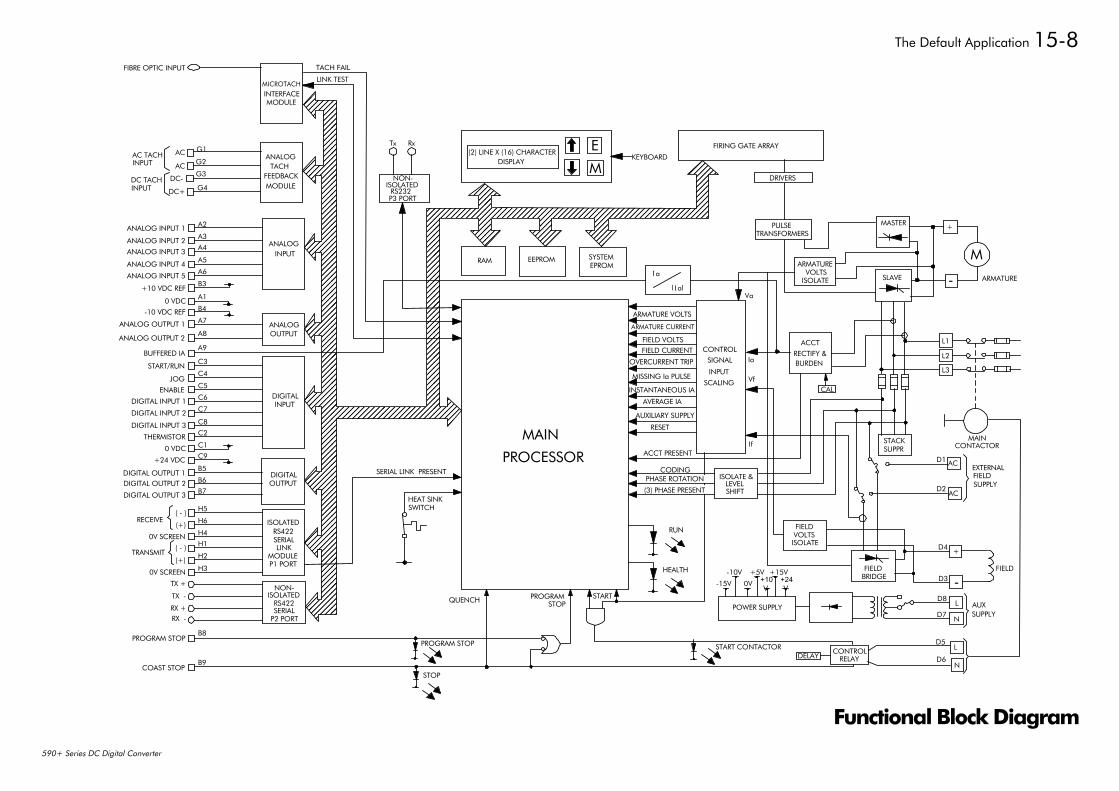
The Default Application 15-8
590+ Series DC Digital Converter
ANALOG INPUT 1
ANALOG INPUT 2
ANALOG INPUT 3
ANALOG INPUT 4
ANALOG INPUT 5
+10 VDC REF
0 VDC
-10 VDC REF
ANALOG OUTPUT 1
ANALOG OUTPUT 2
BUFFERED IA
START/RUN
JOG
ENABLE
DIGITAL INPUT 1
DIGITAL INPUT 2
DIGITAL INPUT 3
THERMISTOR
0 VDC
+24 VDC
DIGITAL OUTPUT 1DIGITAL OUTPUT 2
DIGITAL OUTPUT 3
( - )
(+)RECEIVE
0V SCREEN
( - )
(+)TRANSMIT
0V SCREEN
TX +
TX -
RX +RX -
PROGRAM STOP
COAST STOP
B8
B9
NON-ISOLATED
RS422SERIAL
P2 PORT
H3
H2
H1
H4
H6
H5
ISOLATEDRS422SERIALLINK
MODULEP1 PORT
B7
B6
B5DIGITALOUTPUT
C9
C1
C2
C8
C7
C6
C5
C4
C3
DIGITALINPUT
A9
A8
A7
B4
A1
B3
A6
A5
A4
A3
A2
ANALOGINPUT
ANALOGOUTPUT
FIBRE OPTIC INPUT
MICROTACHINTERFACEMODULE
LINK TEST
TACH FAIL
Tx Rx
NON-ISOLATED
RS232P3 PORT
(2) LINE X (16) CHARACTERDISPLAY
E
MKEYBOARD
FIRING GATE ARRAY
DRIVERS
PULSETRANSFORMERS
MASTER +
-
MARMATURE
ARMATUREVOLTS
ISOLATE SLAVE
Va
a
al
I
Il
SYSTEMEPROM
EEPROMRAM
HEAT SINKSWITCH
SERIAL LINK PRESENT
ARMATURE VOLTS
ARMATURE CURRENT
FIELD VOLTSFIELD CURRENT
OVERCURRENT TRIP
MISSING Ia PULSE
INSTANTANEOUS IA
AVERAGE IA
AUXILIARY SUPPLY
RESET
ACCT PRESENT
CODINGISOLATE &
LEVELSHIFT
ACCT
RECTIFY &BURDEN
RUN
HEALTH
Ia
Vf
If
CAL
(3) PHASE PRESENT
PHASE ROTATION
STARTPROGRAMSTOPQUENCH
PROGRAM STOP
STOP
CONTROLRELAYDELAY
D5
D6
L
N
START CONTACTOR
POWER SUPPLY
-15V 0V +10V
+24V
-10V +5V +15V
D7
D8L
N
AUXSUPPLY
FIELD
+
-D3
D4
FIELDBRIDGE
FIELDVOLTSISOLATE
AC
ACD1
D2
EXTERNALFIELDSUPPLY
MAINCONTACTOR
STACKSUPPR
L1
L2
L3
MAIN
PROCESSOR
CONTROLSIGNAL
INPUT
SCALING
G3DC-
ACG2
G1ANALOG
TACH
MODULEFEEDBACK
AC
DC+ G4
AC TACHINPUT
DC TACHINPUT
Functional Block Diagram
ISS. MODIFICATION ECN No. DATE DRAWN CHK'D
1 HA466461U002 - Contains Frame 4 and softwareversion 5.x. Replaces manual HA466461U001.
16158 7/8/01 CM GR
FIRST USED ON MODIFICATION RECORD
590+ Series DC Digital Converter
EUROTHERM DRIVES
DRAWING NUMBER
ZZ466461U002
SHT. 1
OF 1