Embed Size (px)
Citation preview

6 April 2020

Point of observation
Figures © Stephen E. Palmer, 2002
Dimensionality Reduction Machine (3D to 2D)
3D world 2D image
Lengths are lost…
…and so area is lost.
Angle preservation is lost…
…so parallel/perpendicular lines are lost.
How can we recover scene geometry to measure the world?

Slide Credit: Savarese
Camera (projection) matrix
Ow
iw
kw
jwR,t
X
x
=
1100
0
1 333231
232221
131211
0
0
z
y
x
trrr
trrr
trrr
vf
usf
v
u
w
z
y
x
y
x
XtRKx =x: Image Coordinates: (u,v,1)
K: Intrinsic Matrix (3x3)
R: Rotation (3x3)
t: Translation (3x1)
X: World Coordinates: (X,Y,Z,1)Extrinsic Matrix

Calibrating the Camera
Use an scene with known geometry
– Correspond image points to 3d points
– Get least squares solution (or non-linear solution)
=
134333231
24232221
14131211
Z
Y
X
mmmm
mmmm
mmmm
s
sv
su
Known 3d
world locationsKnown 2d
image coords
Unknown Camera Parameters
James Hays
M

Can we factorize M back to K [R | T]?
• Yes!
• We can directly solve for the individual entries of K [R | T].
James Hays

James Hays
an = nth
column of A

James Hays

James Hays
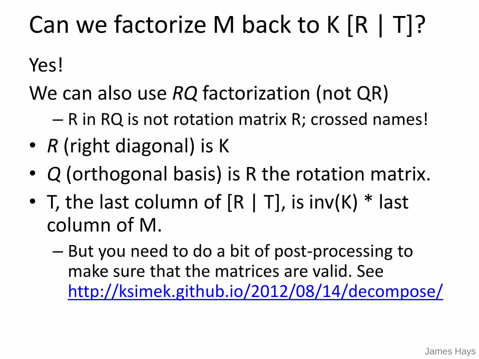
Can we factorize M back to K [R | T]?
Yes!
We can also use RQ factorization (not QR)– R in RQ is not rotation matrix R; crossed names!
• R (right diagonal) is K
• Q (orthogonal basis) is R the rotation matrix.
• T, the last column of [R | T], is inv(K) * last column of M.– But you need to do a bit of post-processing to
make sure that the matrices are valid. See http://ksimek.github.io/2012/08/14/decompose/
James Hays

Recovering the camera center
=
1****
****
****
Z
Y
X
s
sv
su
XtRKx =
=
1100
0
1 333231
232221
131211
0
0
z
y
x
trrr
trrr
trrr
v
us
v
u
w
z
y
x
This is not the camera
center C.
It is –RC, as the point
is rotated before tx, ty,
and tz are added
This is t × K
Q
So K-1 m4 is t
So we need
-R-1 K-1 m4 to get C.
Q is K × R.
So we just need -Q-1 m4
James Hays
m4
t

Estimate of camera center
1.5706 -0.1490 0.2598
-1.5282 0.9695 0.3802
-0.6821 1.2856 0.4078
0.4124 -1.0201 -0.0915
1.2095 0.2812 -0.1280
0.8819 -0.8481 0.5255
-0.9442 -1.1583 -0.3759
0.0415 1.3445 0.3240
-0.7975 0.3017 -0.0826
-0.4329 -1.4151 -0.2774
-1.1475 -0.0772 -0.2667
-0.5149 -1.1784 -0.1401
0.1993 -0.2854 -0.2114
-0.4320 0.2143 -0.1053
-0.7481 -0.3840 -0.2408
0.8078 -0.1196 -0.2631
-0.7605 -0.5792 -0.1936
0.3237 0.7970 0.2170
1.3089 0.5786 -0.1887
1.2323 1.4421 0.4506
1.0486 -0.3645
-1.6851 -0.4004
-0.9437 -0.4200
1.0682 0.0699
0.6077 -0.0771
1.2543 -0.6454
-0.2709 0.8635
-0.4571 -0.3645
-0.7902 0.0307
0.7318 0.6382
-1.0580 0.3312
0.3464 0.3377
0.3137 0.1189
-0.4310 0.0242
-0.4799 0.2920
0.6109 0.0830
-0.4081 0.2920
-0.1109 -0.2992
0.5129 -0.0575
0.1406 -0.4527

Great! So now I have K and Rt
Well, what is that useful for?
Goal: reconstruct depth.
So far: we have ‘calibrated’ one camera.
Or, potentially two…

Think-Pair-Share
What visual or physiological cues help us to
perceive 3D shape and depth?

Shading
[Figure from Prados & Faugeras 2006]

Focus/defocus
[figs from H. Jin and P. Favaro, 2002]
Images from
same point of
view, different
camera
parameters
3d shape / depth
estimates

Texture
[From A.M. Loh. The recovery of 3-D structure using visual texture patterns. PhD thesis]

Perspective effects
Image credit: S. Seitz

Motion
Figures from L. Zhang http://www.brainconnection.com/teasers/?main=illusion/motion-shape

Occlusion
Rene Magritt'e famous painting Le Blanc-Seing (literal translation: "The Blank Signature") roughly translates as "free hand" or "free rein".

Stereo
Slides: James Hays and Kristen Grauman

If stereo were critical for depth
perception, navigation, recognition, etc.,
then rabbits would never have evolved.


Devin Montes

Human stereopsisHuman eyes fixate on point in space – rotate so that corresponding images form in centers of fovea.

Disparity occurs when
eyes fixate on one object;
others appear at different
visual angles.
Disparity is distance from
b1 to b2 along retina.
Human stereopsis: disparity

Yes, you can be stereoblind.

Random dot stereograms
• Julesz 1960:
Do we identify local brightness patterns before fusion (monocular process) or after (binocular)?
• Think Pair Share – yes / no? how to test?

Random dot stereograms
• Julesz 1960:
Do we identify local brightness patterns before fusion (monocular process) or after (binocular)?
• To test: pair of synthetic images obtained by randomly spraying black dots on white objects

Random dot stereograms
Forsyth & Ponce

Random dot stereograms

1. Create an image of suitable size. Fill it with random dots. Duplicate the image.
2. Select a region in one image.
CC BY-SA 3.0, https://en.wikipedia.org/wiki/Random_dot_stereogram
3. Shift this region horizontally by a small amount. The stereogram is complete.

CC BY-SA 3.0, https://en.wikipedia.org/wiki/Random_dot_stereogram

Random dot stereograms
• When viewed monocularly, they appear random; when viewed stereoscopically, see 3d structure.
• Human binocular fusion not directly associated with the physical retinas; must involve the central nervous system (V2, for instance).
• Imaginary “cyclopean retina” that combines the left and right image stimuli as a single unit.
• High level scene understanding not required for stereo…but, high level scene understanding is arguably better than stereo.

Autostereograms – ‘Magic Eye’
Images from magiceye.com
Exploit disparity as
depth cue using single
image.
(Single image random
dot stereogram, Single
image stereogram)

Images from magiceye.com
Autostereograms

Stereo attention is weird wrt. mind’s eye
[Li Zhaoping, Understanding Vision]

Stereo photography and stereo viewers
Invented by Sir Charles Wheatstone, 1838Image from fisher-price.com
Take two pictures of the same subject from two slightly
different viewpoints and display so that each eye sees
only one of the images.

Anaglyph stereo
http://www.johnsonshawmuseum.org

http://www.johnsonshawmuseum.org

Wiggle images
http://www.well.com/~jimg/stereo/stereo_list.html


Frederick Kingdom

Frederick Kingdom

Photo: Georges Jansoon. Illusion: Frederick Kingdom, Ali Yoonessi and Elena
Gheorghiu

Frederick Kingdom

Two cameras, simultaneous
views
Single moving camera and
static scene
Stereo vision

Why multiple views?
Structure and depth can be ambiguous from single views...
Images from Lana Lazebnik

Why multiple views?
Points at different depths along a line project to a single point
Optical center
P1
P2
P1’=P2’

Multiple views
Hartley and Zisserman
Lowe
Stereo vision
Structure from motion
Optical flow

Multi-view geometry problems
• Camera ‘Motion’: Given a set of corresponding 2D/3D
points in two or more images, compute the camera
parameters.
Camera 1Camera 2 Camera 3
R1,t1 R2,t2R3,t3? ? ? Slide credit:
Noah Snavely

Multi-view geometry problems
• Stereo correspondence: Given known camera
parameters and a point in one of the images, where could
its corresponding points be in the other images?
Camera 3
R3,t3
Camera 1Camera 2
R1,t1 R2,t2Slide credit:
Noah Snavely

Multi-view geometry problems
• Structure from Motion: Given projections of the same 3D
point in two or more images, compute the 3D coordinates
of that point
Camera 3
R3,t3 Slide credit:
Noah Snavely
?
Camera 1Camera 2
R1,t1 R2,t2? ? ?

Multi-view geometry problems
• Optical flow: Given two images, find the location of a world
point in a second close-by image with no camera info.
Camera 1
Camera 2

Multiple views - Dogception

Estimating depth with stereo
• Stereo: shape from “motion” between two views
• We’ll need to consider:
• Info on camera pose (“calibration”)
• Image point correspondences
scene point
optical
center
image plane
James Hays

Geometry for a simple stereo system
• Assume:
– parallel optical axes,
– known camera parameters
(i.e., calibrated cameras):
• Goal: recover depth of X
by finding image coordinate
x’ that corresponds to x
X
x
x'

baseline
optical
center
(left)
optical
center
(right)
Focal
length
World
point
image point
(left)
image point
(right)
Depth of p

• Assume parallel optical axes, known camera parameters
(i.e., calibrated cameras). What is expression for Z?
Similar triangles (pl, P, pr) and
(Ol, P, Or):
Geometry for a simple stereo system
Z
T
fZ
xxT rl =−
−+
lr xx
TfZ
−=
disparity

Depth from disparity
image I(x,y) image I´(x´,y´)Disparity map D(x,y)
(x´,y´)=(x+D(x,y), y)
If we could find the corresponding points in two images, we
could estimate relative depth…
James Hays

Depth from disparity
• Goal: recover depth by finding image coordinate x’ that corresponds to x
• Sub-Problems
1. Calibration: How do we recover the relation of the cameras (if not already known)?
2. Correspondence: How do we search for the matching point x’?
X
x
x'

What do we need to know?
1. Calibration for the two cameras.
1. Intrinsic matrices for both cameras (e.g., f)
2. Baseline distance T in parallel camera case
3. R, t in non-parallel case
2. Correspondence for every pixel.
Like project 2, but project 2 is “sparse”.
We need “dense” correspondence!

Correspondence for every pixel.Where do we need to search?

Wouldn’t it be nice to know where matches can live?
Epipolar geometryConstrains 2D search to 1D

Potential matches for x have to
lie on the corresponding line l’.
Potential matches for x’ have to
lie on the corresponding line l.
Key idea: Epipolar constraint
x x’
X
x’
X
x’
X

• Epipolar Plane – plane containing baseline (1D family)
• Epipoles
= intersections of baseline with image planes
= projections of the other camera center
• Baseline – line connecting the two camera centers
Epipolar geometry: notationX
x x’

• Epipolar Lines - intersections of epipolar plane with image
planes (always come in corresponding pairs)
Epipolar geometry: notationX
x x’
• Epipolar Plane – plane containing baseline (1D family)
• Epipoles
= intersections of baseline with image planes
= projections of the other camera center
• Baseline – line connecting the two camera centers

Think Pair Share
Where are the epipoles?
What do the epipolar lines look like?
X
a)X
b)
X
c)X
d)
= camera center

Example: Converging cameras

Example: Motion parallel to image plane

e
e’
Example: Forward motion
Epipole has same coordinates in both
images.
Points move along lines radiating from e:
“Focus of expansion”

What is this useful for?
Reduce search space for stereo disparity estimation.
• Help find x’: If I know x, and have calibrated cameras (known intrinsics K,K’ and extrinsic relationship), I can restrict x’ to be along l’.
X
x x’

Epipolar lines

What is this useful for?
If we have enough x, x’ correspondences, we can estimate relative position and orientation between the cameras and the 3D position of corresponding image points -> estimate E.
X
x x’

What is this useful for?
Camera model ‘sanity check’:
• See if candidate x, x’ correspondences fit estimated projection models of cameras 1 and 2.
X
x x’

VLFeat’s 800 most confident matches among 10,000+ local features.

Keep only the matches at are “inliers” with respect to the “best” fundamental matrix

Epipolar constraint: Calibrated case
x x’
X
XxKx1 ==−ˆ
ො𝑥′ො𝑥
XxKx1
==−ˆ
Homogeneous 2d point
(3D ray towards X) 2D pixel coordinate
(homogeneous)
3D scene point
3D scene point in 2nd
camera’s 3D coordinates
Intrinsics K
Intrinsics K’

Epipolar constraint: Calibrated case
x x’
X
t
XxKx1 ==−ˆ
0)]ˆ([ˆ = xRtx
(because ො𝑥, 𝑅 ො𝑥′, and 𝑡 are co-planar)
ො𝑥′ො𝑥
XxKx1
==−ˆ
Homogeneous 2d point
(3D ray towards X) 2D pixel coordinate
(homogeneous)
3D scene point
3D scene point in 2nd
camera’s 3D coordinates
Intrinsics K
Intrinsics K’

Essential Matrix
(Longuet-Higgins, 1981)
Essential matrix
0)]ˆ([ˆ = xRtx RtExExT
== with0ˆˆ
X
x x’
E is a 3x3 matrix which relates
corresponding pairs of normalized
homogeneous image points across pairs of
images – for intrinsic K calibrated cameras.
Estimates relative position/orientation. Note: [t]× is matrix representation of cross product

Epipolar constraint: Uncalibrated case
If we don’t know intrinsics K and K’, then we can write the epipolar constraint in terms of unknown normalized coordinates:
X
x x’
0ˆˆ =xExT xKxxKx == ˆ,ˆ

The Fundamental Matrix
Fundamental Matrix
(Faugeras and Luong, 1992)
0ˆˆ =xExT
1with0
−− == KEKFxFxTT
Without knowing K and K’, we can define a similar
relation using unknown normalized coordinates
xKx1−
=ˆ
xKx1 =
−ˆ

Properties of the Fundamental matrix
1with0
−− == KEKFxFxTT
• F x’ = 0 is the epipolar line l associated with x’
• FTx = 0 is the epipolar line l’ associated with x
• F is singular (rank two): det(F)=0
• F e’ = 0 and FTe = 0 (nullspaces of F = e’; nullspace of FT = e’)
• F has seven degrees of freedom: 9 entries but defined up to scale, det(F)=0
X
x x’

F in more detail
• F is a 3x3 matrix• Rank 2 -> projection; one column is a linear
combination of the other two.• Determined up to scale.• 7 degrees of freedom
𝑎 𝑏 𝛼𝑎 + 𝛽𝑏𝑐 𝑑 𝛼𝑐 + 𝛽𝑑𝑒 𝑓 𝛼𝑒 + 𝛽𝑓
where a is scalar; e.g., can normalize out.
Given x projected from X into image 1, F constrains the projection of x’ into image 2 to an epipolar line.

Estimating the Fundamental Matrix
• 8-point algorithm
– Least squares solution using SVD on equations from 8 pairs of correspondences
– Enforce det(F)=0 constraint using SVD on F
Note: estimation of F (or E) is degenerate for a planar scene.

8-point algorithm
1. Solve a system of homogeneous linear equations
a. Write down the system of equations
0=xx FT
𝑢𝑢′𝑓11 + 𝑢𝑣′𝑓12 + 𝑢𝑓13 + 𝑣𝑢′𝑓21 + 𝑣𝑣′𝑓22 + 𝑣𝑓23 + 𝑢′𝑓31 + 𝑣′𝑓32 + 𝑓33 = 0
A𝒇 =𝑢1𝑢1′ 𝑢1𝑣1′ 𝑢1 𝑣1𝑢1′ 𝑣1𝑣1′ 𝑣1 𝑢1′ 𝑣1′ 1⋮
𝑢𝑛𝑢𝑣′
⋮𝑢𝑛𝑣𝑛′
⋮𝑢𝑛
⋮𝑣𝑛𝑢𝑛′
⋮𝑣𝑛𝑣𝑛′
⋮𝑣𝑛
⋮𝑢𝑛′
⋮𝑣𝑛′
⋮1
𝑓11𝑓12𝑓13𝑓21⋮𝑓33
=0

8-point algorithm
1. Solve a system of homogeneous linear equations
a. Write down the system of equations
b. Solve f from Af=0 using SVD
Matlab: [U, S, V] = svd(A);f = V(:, end);F = reshape(f, [3 3])’;
Python Numpy:U, S, Vh = np.linalg.svd(A)# V = Vh.T -> note = different from MATLABF = Vh[-1,:]F = np.reshape(F, (3,3))

Need to enforce singularity constraint

8-point algorithm
1. Solve a system of homogeneous linear equations
a. Write down the system of equations
b. Solve f from Af=0 using SVD
2. Resolve det(F) = 0 constraint using SVD
Matlab: [U, S, V] = svd(A);
f = V(:, end);
F = reshape(f, [3 3])’;
Matlab: [U, S, V] = svd(F);
S(3,3) = 0;
F = U*S*V’;
Python Numpy:U, S, Vh = np.linalg.svd(F)S[-1] = 0F = U @ np.diagflat(S) @ Vh
Python Numpy:U, S, Vh = np.linalg.svd(A)F = Vh[-1,:]F = np.reshape(F, (3,3))
@ operator = matrix multiplication

Problem with eight-point algorithm
1
32
31
23
22
21
13
12
11
−=
f
f
f
f
f
f
f
f
vuvvvuvuvuuu

1
32
31
23
22
21
13
12
11
−=
f
f
f
f
f
f
f
f
vuvvvuvuvuuu
Problem with eight-point algorithm
Poor numerical conditioning
Can be fixed by rescaling the data

The normalized eight-point algorithm
• Center the image data at the origin, and scale it so
the mean squared distance between the origin and
the data points is 2 pixels
• Use the eight-point algorithm to compute F from the
normalized points
• Enforce the rank-2 constraint (for example, take SVD
of F and throw out the smallest singular value)
• Transform fundamental matrix back to original units:
if T and T’ are the normalizing transformations in the
two images, than the fundamental matrix in original
coordinates is T’T F T
(Hartley, 1995)

Comparison of estimation algorithms
8-point Normalized 8-point Nonlinear least squares
Av. Dist. 1 2.33 pixels 0.92 pixel 0.86 pixel
Av. Dist. 2 2.18 pixels 0.85 pixel 0.80 pixel

From epipolar geometry to camera calibration
• If we know the calibration matrices of the two cameras, we can estimate the essential matrix: E = KTFK’
• The essential matrix gives us the relative rotation and translation between the cameras, or their extrinsic parameters.
• Fundamental matrix lets us compute relationship up to scale for cameras with unknown intrinsic calibrations.
• Estimating the fundamental matrix is a kind of “weak calibration”

Let’s recap…
• Fundamental matrix song
• http://danielwedge.com/fmatrix/

Among all my matches, how do I know which ones are good?

Example: solving for translation
A1
A2 A3B1
B2 B3
Given matched points in {A} and {B}, estimate the translation of the object
+
=
y
x
A
i
A
i
B
i
B
i
t
t
y
x
y
x
(tx, ty)

Example: solving for translation
A1
A2 A3B1
B2 B3
+
=
y
x
A
i
A
i
B
i
B
i
t
t
y
x
y
x
(tx, ty)
Problem: outliers A4-B4 and A5-B5 which incorrectly correspond
A4
A5
B5
B4

Least squares: Robustness to noise
• Least squares fit to the red points:

Least squares line fitting•Data: (x1, y1), …, (xn, yn)
•Line equation: yi = m xi + b
•Find (m, b) to minimize
=−−=
n
i ii bxmyE1
2)(
(xi, yi)
y=mx+b
Matlab: p = A \ y;Python: p = np.linalg.lstsq(A,y)[0]
Modified from S. Lazebnik
(Closed form solution)

Least squares: Robustness to noise
• Least squares fit with an outlier:
Problem: squared error heavily penalizes outliers

Robust least squares (to deal with outliers)General approach:
minimize
ui (xi, θ) – residual of ith point w.r.t. model parameters ϴ
( )( ) ;,ii
i
xu
The robust function ρ• Favors a configuration
with small residuals
• Constant penalty for large
residuals
=−−=
n
i ii bxmyu1
22)(
Slide from S. Savarese
ρ – robust function with scale parameter σ
Effect of scale
parameter σ

Choosing the scale: Just right
The effect of the outlier is minimized

The error value is almost the same for every
point and the fit is very poor
Choosing the scale: Too small

Choosing the scale: Too large
Behaves much the same as least squares

Robust estimation: Details
• Robust fitting is a nonlinear optimization problem that must be solved iteratively
• Scale of robust function should be chosen adaptively based on median residual
• Least squares solution can be used for initialization

VLFeat’s 800 most confident matches among 10,000+ local features.
What if I have many outliers?
Episcopal Gaudi image pair

Example: solving for translation
A1
A2 A3B1
B2 B3
Given matched points in {A} and {B}, estimate the translation of the object
+
=
y
x
A
i
A
i
B
i
B
i
t
t
y
x
y
x
(tx, ty)

Example: solving for translation
A1
A2 A3B1
B2 B3
RANSAC solution
+
=
y
x
A
i
A
i
B
i
B
i
t
t
y
x
y
x
(tx, ty)
1. Sample a set of matching points (1 pair)
2. Solve for transformation parameters
3. Score parameters with number of inliers
4. Repeat steps 1-3 N times
Problem: outliers A4-B4 and A5-B5 which incorrectly correspond
A4
A5
B5
B4

RANSAC
Fischler & Bolles in ‘81.
(RANdom SAmple Consensus) :

RANSAC
Fischler & Bolles in ‘81.
(RANdom SAmple Consensus) :

RANSAC
Fischler & Bolles in ‘81.
(RANdom SAmple Consensus) :
This data is noisy, but we expect a good fit
to a known model.

RANSAC
Fischler & Bolles in ‘81.
(RANdom SAmple Consensus) :
This data is noisy, but we expect a good fit
to a known model.
Here, we expect to see a line, but least-
squares fitting will produce the wrong result
due to strong outlier presence.

RANSAC
Algorithm:
1. Sample (randomly) the number of points s required to fit the model
2. Solve for model parameters using samples
3. Score by the fraction of inliers within a preset threshold of the model
Repeat 1-3 until the best model is found with high confidence
Fischler & Bolles in ‘81.
(RANdom SAmple Consensus) :

RANSAC
Algorithm:
1. Sample (randomly) the number of points required to fit the model (s=2)
2. Solve for model parameters using samples
3. Score by the fraction of inliers within a preset threshold of the model
Repeat 1-3 until the best model is found with high confidence
Illustration by Savarese
Line fitting example

RANSAC
Algorithm:
1. Sample (randomly) the number of points required to fit the model (s=2)
2. Solve for model parameters using samples
3. Score by the fraction of inliers within a preset threshold of the model
Repeat 1-3 until the best model is found with high confidence
Line fitting example

RANSAC
6=InliersN
Algorithm:
1. Sample (randomly) the number of points required to fit the model (s=2)
2. Solve for model parameters using samples
3. Score by the fraction of inliers within a preset threshold of the model
Repeat 1-3 until the best model is found with high confidence
Line fitting example

RANSAC
14=InliersNAlgorithm:
1. Sample (randomly) the number of points required to fit the model (s=2)
2. Solve for model parameters using samples
3. Score by the fraction of inliers within a preset threshold of the model
Repeat 1-3 until the best model is found with high confidence

How to choose parameters?• Number of algorithm iterations N
– Choose N so that, with probability p, at least one random sample is free from outliers (e.g., p=0.99) (outlier ratio: e)
• Number of sampled points s– Minimum number needed to fit the model
• Distance threshold – Choose so that a good point with noise is likely (e.g., prob=0.95)
within threshold– Zero-mean Gaussian noise with std. dev. σ: t2=3.84σ2
( ) ( )( )sepN −−−= 11log/1log
Proportion of outliers e
s 5% 10% 20% 25% 30% 40% 50%
2 2 3 5 6 7 11 17
3 3 4 7 9 11 19 35
4 3 5 9 13 17 34 72
5 4 6 12 17 26 57 146
6 4 7 16 24 37 97 293
7 4 8 20 33 54 163 588
8 5 9 26 44 78 272 1177
modified from M. PollefeysFor p = 0.99
How many iterations
do I need?

VLFeat’s SIFT produces 800 most confident matches among 10,000+ local features.

Epipolar lines

Keep only the matches at are “inliers” with respect to the “best” fundamental matrix

RANSAC conclusions
Good• Robust to outliers• Applicable for large number of objective function parameters
(than Hough transform)• Optimization parameters are easier to choose (than Hough
transform)
Bad• Computational time grows quickly with fraction of outliers
and number of parameters • Not good for getting multiple fits
Common applications• Estimating fundamental matrix (relating two views)• Computing a homography (e.g., image stitching)

SCANLINE ALIGNMENT VIARECTIFICATION
Found F – now what?

Stereo image rectification

Stereo image rectification
• Reproject image planes onto a common plane parallel to the line between camera centers
• Pixel motion is horizontal after this transformation
• Two homographies (3x3 transform), one for each input image reprojection
➢ C. Loop and Z. Zhang. Computing Rectifying Homographies for Stereo Vision. IEEE Conf. Computer Vision and Pattern Recognition, 1999.

Rectification example