Embed Size (px)
Citation preview
Catalog – GM2004 71
6
1
2
3
4
7
8
9
10
11
12
13
14
15
16
17
18
19
20
21
22
LubricantsDesign and Operating Notes
6
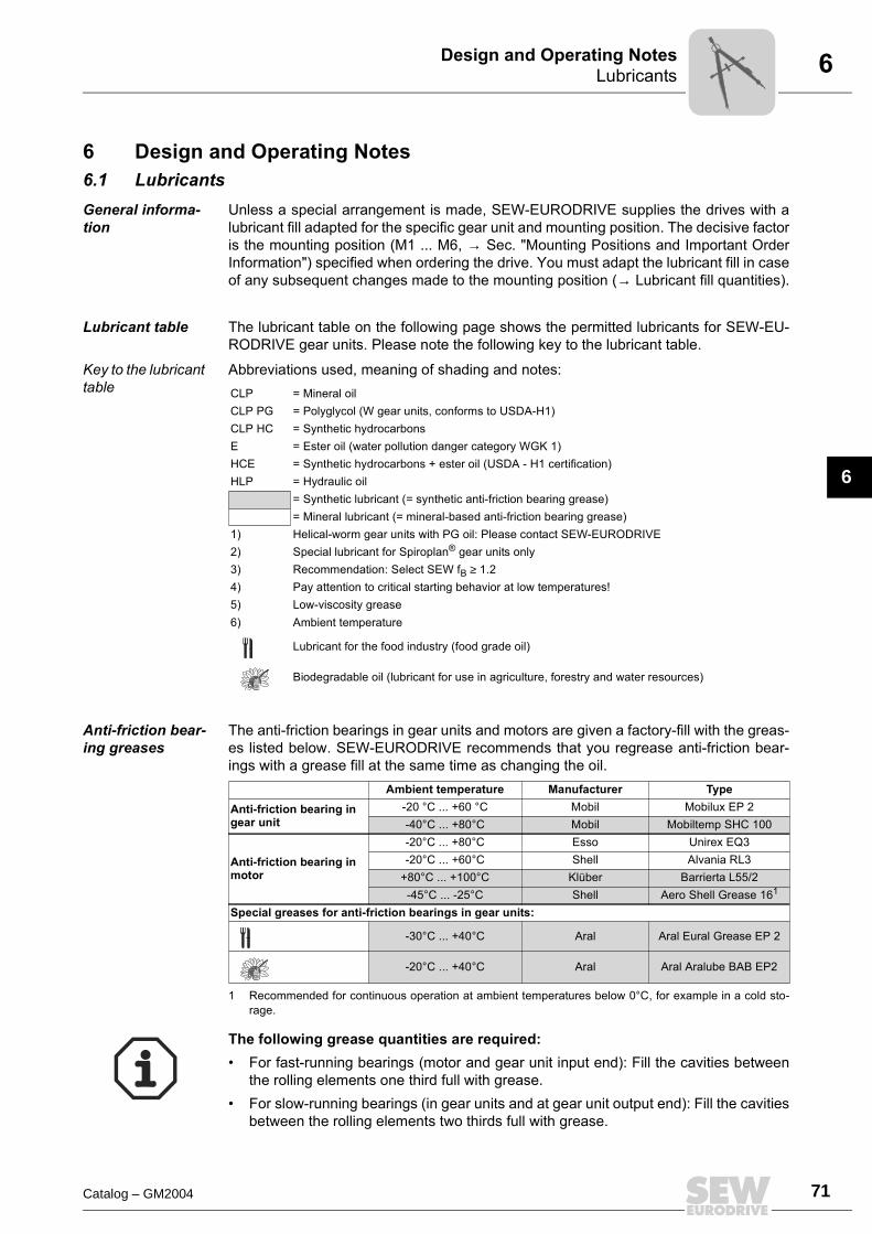
6 Design and Operating Notes6.1 LubricantsGeneral informa-tion
Unless a special arrangement is made, SEW-EURODRIVE supplies the drives with alubricant fill adapted for the specific gear unit and mounting position. The decisive factoris the mounting position (M1 ... M6, → Sec. "Mounting Positions and Important OrderInformation") specified when ordering the drive. You must adapt the lubricant fill in caseof any subsequent changes made to the mounting position (→ Lubricant fill quantities).
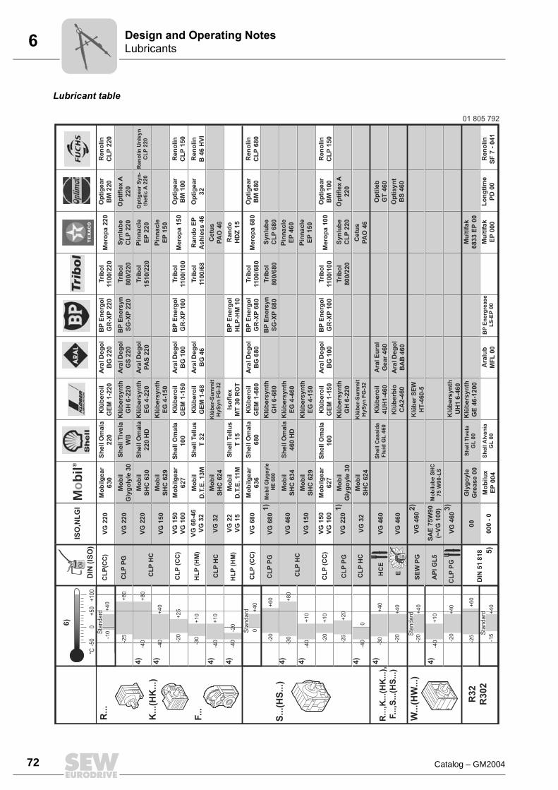
Lubricant table The lubricant table on the following page shows the permitted lubricants for SEW-EU-RODRIVE gear units. Please note the following key to the lubricant table.
Key to the lubricant table
Abbreviations used, meaning of shading and notes:
Anti-friction bear-ing greases
The anti-friction bearings in gear units and motors are given a factory-fill with the greas-es listed below. SEW-EURODRIVE recommends that you regrease anti-friction bear-ings with a grease fill at the same time as changing the oil.
CLP = Mineral oilCLP PG = Polyglycol (W gear units, conforms to USDA-H1)CLP HC = Synthetic hydrocarbonsE = Ester oil (water pollution danger category WGK 1)HCE = Synthetic hydrocarbons + ester oil (USDA - H1 certification)HLP = Hydraulic oil
= Synthetic lubricant (= synthetic anti-friction bearing grease)= Mineral lubricant (= mineral-based anti-friction bearing grease)
1) Helical-worm gear units with PG oil: Please contact SEW-EURODRIVE2) Special lubricant for Spiroplan® gear units only3) Recommendation: Select SEW fB ≥ 1.24) Pay attention to critical starting behavior at low temperatures!5) Low-viscosity grease6) Ambient temperature
Lubricant for the food industry (food grade oil)
Biodegradable oil (lubricant for use in agriculture, forestry and water resources)OilOil
Ambient temperature Manufacturer TypeAnti-friction bearing in gear unit
-20 °C ... +60 °C Mobil Mobilux EP 2-40°C ... +80°C Mobil Mobiltemp SHC 100
Anti-friction bearing in motor
-20°C ... +80°C Esso Unirex EQ3-20°C ... +60°C Shell Alvania RL3
+80°C ... +100°C Klüber Barrierta L55/2-45°C ... -25°C Shell Aero Shell Grease 161
1 Recommended for continuous operation at ambient temperatures below 0°C, for example in a cold sto-rage.
Special greases for anti-friction bearings in gear units:
-30°C ... +40°C Aral Aral Eural Grease EP 2
-20°C ... +40°C Aral Aral Aralube BAB EP2OilOil
The following grease quantities are required:� For fast-running bearings (motor and gear unit input end): Fill the cavities between
the rolling elements one third full with grease.� For slow-running bearings (in gear units and at gear unit output end): Fill the cavities
between the rolling elements two thirds full with grease.
6
72 Catalog – GM2004
LubricantsDesign and Operating Notes
Lubricant table
Oil
Oil
Oil
VG
22
0B
P E
ne
rgo
l
GR
-XP
22
0
VG
22
0B
P E
ne
rsy
n
SG
-XP
22
0
VG
22
0
VG
15
0
VG
15
0
VG
10
0
VG
15
0
VG
10
0
SA
E 7
5W
90
(~V
G 1
00
)
VG
22
VG
15
VG
68
-46
VG
32
BP
En
erg
ol
GR
-XP
10
0
VG
32
BP
En
erg
ol
HL
P-H
M 1
0
VG
68
0B
P E
ne
rgo
l
GR
-XP
68
0
VG
68
0B
P E
ne
rsy
n
SG
-XP
68
0
VG
46
0
VG
15
0
BP
En
erg
ol
GR
-XP
10
0
BP
En
erg
rease
LS
-EP
00
VG
22
0
VG
32
VG
46
0
VG
46
0
VG
46
0
VG
46
0
00
00
0 -
0
0+
100
+50 +
40
+80
+80
+40
+40
+40
+40
+40
+40+
60
+60
-20
-20
-20
+40
-15
-20
-30
4)
4)
6)
4)
4)
4)
4)
4)
3)
2)
1)
1)
4)
4)
5)
-30
-40
-40-2
0
-25
-40
+80
+10
+10
+10
+20
-25
0
-40
0
-40
+25
-25
-20
-30
-40
-40
+10
+10
-20
-10
-50
Sta
nd
ard
DIN
(IS
O)
ISO
,NL
GI
CL
P(C
C)
CL
P P
G
CL
P (
CC
)
CL
P (
CC
)
CL
P H
C
HL
P (
HM
)
HL
P (
HM
)
CL
P (
CC
)
CL
P P
G
01 805 792
CL
P H
C
CL
P H
C
CL
P P
G
CL
P H
C
SE
W P
G
AP
I G
L5
CL
P P
G
DIN
51
81
8
EHC
E
R...
K...(
HK
...)
F...
S...(
HS
...)
R..
.,K
...(
HK
...)
,
F..
.,S
...(
HS
...)
R32
R302
W...(
HW
...)
Re
no
lin
CL
P 2
20
Op
tig
ea
r
BM
22
0M
ero
pa
22
0Tri
bo
l
11
00
/22
0
Op
tifl
ex
A
22
0
Sy
nlu
be
CL
P 2
20
Tri
bo
l
80
0/2
20
Ren
olin
Un
isyn
CL
P 2
20
Op
tig
ear
Syn
-th
eti
c A
220
Pin
na
cle
EP
22
0
Pin
na
cle
EP
15
0
Pin
na
cle
EP
46
0
Pin
na
cle
EP
15
0
Ra
nd
o E
P
As
hle
ss
46
Ce
tus
PA
O 4
6
Ce
tus
PA
O 4
6
Tri
bo
l
15
10
/22
0
Re
no
lin
CL
P 1
50
Op
tig
ea
r
BM
10
0M
ero
pa
15
0Tri
bo
l
11
00
/10
0
Re
no
lin
B 4
6 H
VI
Op
tig
ea
r
32
Tri
bo
l
11
00
/68
Ra
nd
o
HD
Z 1
5
Re
no
lin
CL
P 6
80
Op
tig
ea
r
BM
68
0M
ero
pa
68
0Tri
bo
l
11
00
/68
0
Sy
nlu
be
CL
P 6
80
Sy
nlu
be
CL
P 2
20
Mu
ltif
ak
68
33
EP
00
Mu
ltif
ak
EP
00
0
Tri
bo
l
80
0/6
80
Re
no
lin
CL
P 1
50
Re
no
lin
SF
7 -
04
1
Op
tig
ea
r
BM
10
0M
ero
pa
10
0Tri
bo
l
11
00
/10
0
Op
tifl
ex
A
22
0
Tri
bo
l
80
0/2
20
Op
tile
b
GT
46
0
Op
tis
yn
t
BS
46
0
Lo
ng
tim
e
PD
00
Sh
ell
Om
ala
22
0
Sh
ell
Tiv
ela
WB
Sh
ell
Om
ala
22
0 H
D
Sh
ell
Om
ala
10
0
Sh
ell
Te
llu
s
T 3
2
Sh
ell
Te
llu
s
T 1
5
Sh
ell
Om
ala
68
0
Sh
ell
Om
ala
46
0 H
D
Sh
ell
Om
ala
10
0
Sh
ell C
assid
aF
luid
GL
460
Sh
ell T
ivela
GL
00
Sh
ell A
lvan
iaG
L 0
0
Ara
l D
eg
ol
BG
22
0
Ara
l D
eg
ol
GS
22
0
Ara
l D
eg
ol
PA
S 2
20
Ara
l D
eg
ol
BG
10
0
Ara
l D
eg
ol
BG
46
Ara
l D
eg
ol
BG
68
0
Ara
l D
eg
ol
BG
10
0
Ara
l D
eg
ol
BA
B 4
60
Ara
l E
ura
l
Ge
ar
46
0
Ara
lub
MF
L 0
0
Klü
be
roil
GE
M 1
-22
0
Klü
be
rsy
nth
GH
6-2
20
Klü
be
rsy
nth
EG
4-2
20
Klü
be
rsy
nth
EG
4-1
50
Klü
be
roil
GE
M 1
-15
0
Klü
be
roil
GE
M 1
-68
Klü
ber-
Su
mm
itH
yS
yn
FG
-32
Klü
ber-
Su
mm
itH
yS
yn
FG
-32
Iso
fle
x
MT
30
RO
T
Klü
be
roil
GE
M 1
-68
0
Klü
be
rsy
nth
GH
6-6
80
Klü
be
rsy
nth
EG
4-4
60
Klü
be
rsy
nth
EG
4-1
50
Klü
be
roil
GE
M 1
-15
0
Klü
be
rsy
nth
GH
6-2
20
Klü
be
rsy
nth
GE
46
-12
00
Klü
ber
SE
W
HT-4
60-5
Klü
be
rsy
nth
UH
1 6
-46
0
Klü
be
roil
4U
H1
-46
0
Klü
be
rbio
CA
2-4
60
Mo
bil
ge
ar
63
0
Mo
bil
Gly
go
lyle
30
Mo
bil
SH
C 6
30
Mo
bil
SH
C 6
29
Mo
bil
ge
ar
62
7
Mo
bil
ge
ar
62
7
Mo
bil
D.T
.E.
13
M
Mo
bil
SH
C 6
24
Mo
bil
D.T
.E.
11
M
Mo
bil
ge
ar
63
6
Mo
bil G
lyg
oyle
HE
680
Mo
bil
SH
C 6
34
Mo
bil
SH
C 6
29
Mo
bil
Gly
go
yle
30
Mo
bil
SH
C 6
24
Gly
go
yle
Gre
as
e 0
0
Mo
bil
ux
EP
00
4
Mo
bilu
be S
HC
75 W
90-L
S
°C
Mo
bil®
Oil
Oil
Sta
nd
ard
Sta
nd
ard
Sta
nd
ard
Catalog – GM2004 73
6
1
2
3
4
7
8
9
10
11
12
13
14
15
16
17
18
19
20
21
22
LubricantsDesign and Operating Notes
6
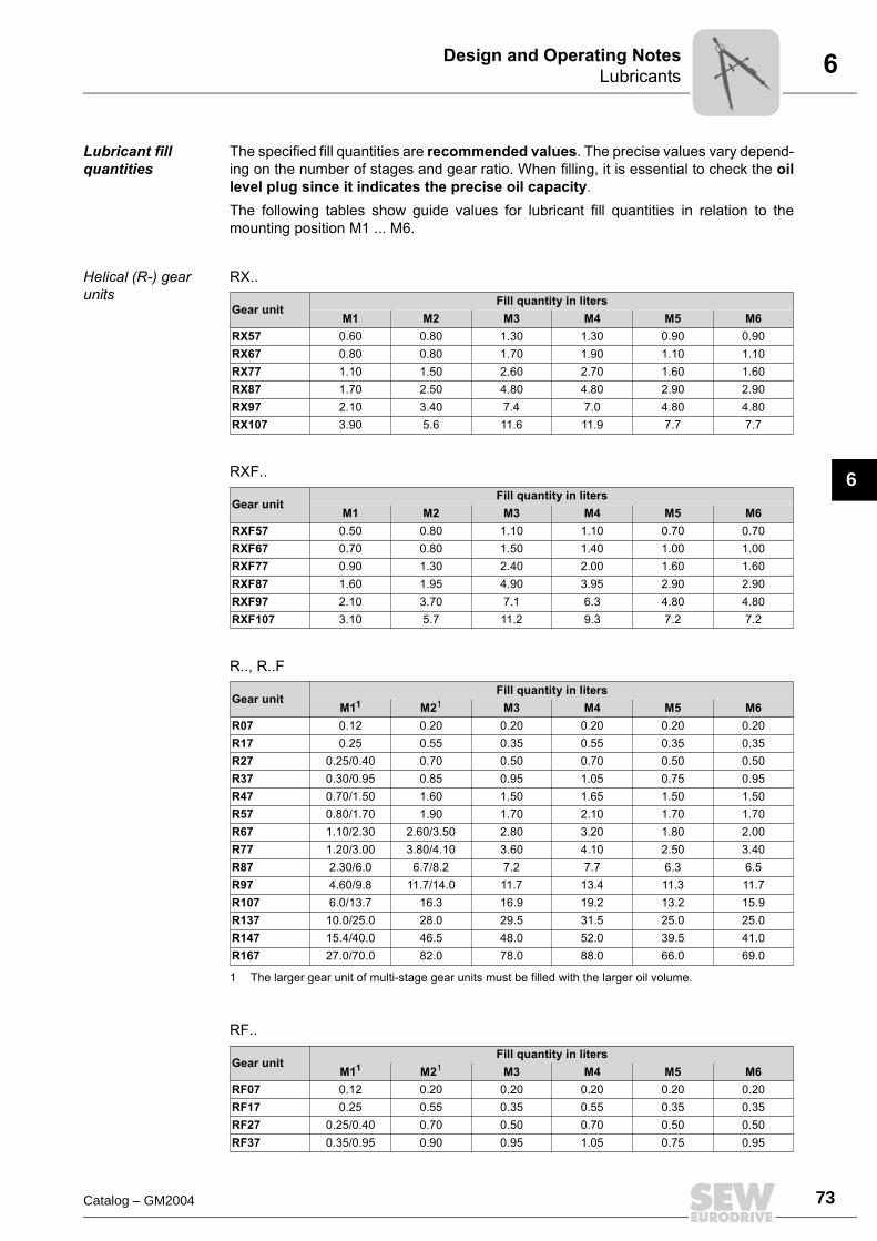
Lubricant fill quantities
The specified fill quantities are recommended values. The precise values vary depend-ing on the number of stages and gear ratio. When filling, it is essential to check the oillevel plug since it indicates the precise oil capacity.The following tables show guide values for lubricant fill quantities in relation to themounting position M1 ... M6.
Helical (R-) gear units
RX..
RXF..
R.., R..F
RF..
Gear unitFill quantity in liters
M1 M2 M3 M4 M5 M6RX57 0.60 0.80 1.30 1.30 0.90 0.90RX67 0.80 0.80 1.70 1.90 1.10 1.10RX77 1.10 1.50 2.60 2.70 1.60 1.60RX87 1.70 2.50 4.80 4.80 2.90 2.90RX97 2.10 3.40 7.4 7.0 4.80 4.80RX107 3.90 5.6 11.6 11.9 7.7 7.7
Gear unitFill quantity in liters
M1 M2 M3 M4 M5 M6RXF57 0.50 0.80 1.10 1.10 0.70 0.70RXF67 0.70 0.80 1.50 1.40 1.00 1.00RXF77 0.90 1.30 2.40 2.00 1.60 1.60RXF87 1.60 1.95 4.90 3.95 2.90 2.90RXF97 2.10 3.70 7.1 6.3 4.80 4.80RXF107 3.10 5.7 11.2 9.3 7.2 7.2
Gear unitFill quantity in liters
M11
1 The larger gear unit of multi-stage gear units must be filled with the larger oil volume.
M21 M3 M4 M5 M6R07 0.12 0.20 0.20 0.20 0.20 0.20R17 0.25 0.55 0.35 0.55 0.35 0.35R27 0.25/0.40 0.70 0.50 0.70 0.50 0.50R37 0.30/0.95 0.85 0.95 1.05 0.75 0.95R47 0.70/1.50 1.60 1.50 1.65 1.50 1.50R57 0.80/1.70 1.90 1.70 2.10 1.70 1.70R67 1.10/2.30 2.60/3.50 2.80 3.20 1.80 2.00R77 1.20/3.00 3.80/4.10 3.60 4.10 2.50 3.40R87 2.30/6.0 6.7/8.2 7.2 7.7 6.3 6.5R97 4.60/9.8 11.7/14.0 11.7 13.4 11.3 11.7R107 6.0/13.7 16.3 16.9 19.2 13.2 15.9R137 10.0/25.0 28.0 29.5 31.5 25.0 25.0R147 15.4/40.0 46.5 48.0 52.0 39.5 41.0R167 27.0/70.0 82.0 78.0 88.0 66.0 69.0
Gear unitFill quantity in liters
M11 M21 M3 M4 M5 M6RF07 0.12 0.20 0.20 0.20 0.20 0.20RF17 0.25 0.55 0.35 0.55 0.35 0.35RF27 0.25/0.40 0.70 0.50 0.70 0.50 0.50RF37 0.35/0.95 0.90 0.95 1.05 0.75 0.95
6
74 Catalog – GM2004
LubricantsDesign and Operating Notes
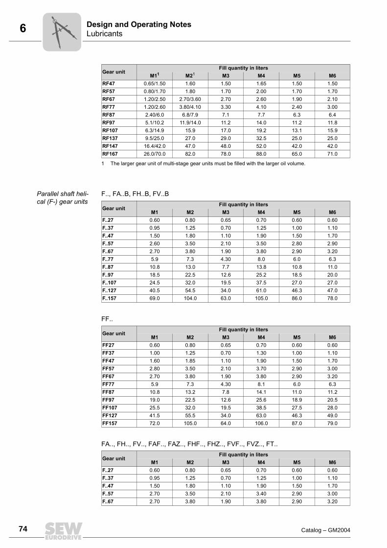
Parallel shaft heli-cal (F-) gear units
F.., FA..B, FH..B, FV..B
FF..
FA.., FH.., FV.., FAF.., FAZ.., FHF.., FHZ.., FVF.., FVZ.., FT..
RF47 0.65/1.50 1.60 1.50 1.65 1.50 1.50RF57 0.80/1.70 1.80 1.70 2.00 1.70 1.70RF67 1.20/2.50 2.70/3.60 2.70 2.60 1.90 2.10RF77 1.20/2.60 3.80/4.10 3.30 4.10 2.40 3.00RF87 2.40/6.0 6.8/7.9 7.1 7.7 6.3 6.4RF97 5.1/10.2 11.9/14.0 11.2 14.0 11.2 11.8RF107 6.3/14.9 15.9 17.0 19.2 13.1 15.9RF137 9.5/25.0 27.0 29.0 32.5 25.0 25.0RF147 16.4/42.0 47.0 48.0 52.0 42.0 42.0RF167 26.0/70.0 82.0 78.0 88.0 65.0 71.0
1 The larger gear unit of multi-stage gear units must be filled with the larger oil volume.
Gear unitFill quantity in liters
M11 M21 M3 M4 M5 M6
Gear unitFill quantity in liters
M1 M2 M3 M4 M5 M6F..27 0.60 0.80 0.65 0.70 0.60 0.60F..37 0.95 1.25 0.70 1.25 1.00 1.10F..47 1.50 1.80 1.10 1.90 1.50 1.70F..57 2.60 3.50 2.10 3.50 2.80 2.90F..67 2.70 3.80 1.90 3.80 2.90 3.20F..77 5.9 7.3 4.30 8.0 6.0 6.3F..87 10.8 13.0 7.7 13.8 10.8 11.0F..97 18.5 22.5 12.6 25.2 18.5 20.0F..107 24.5 32.0 19.5 37.5 27.0 27.0F..127 40.5 54.5 34.0 61.0 46.3 47.0F..157 69.0 104.0 63.0 105.0 86.0 78.0
Gear unitFill quantity in liters
M1 M2 M3 M4 M5 M6FF27 0.60 0.80 0.65 0.70 0.60 0.60FF37 1.00 1.25 0.70 1.30 1.00 1.10FF47 1.60 1.85 1.10 1.90 1.50 1.70FF57 2.80 3.50 2.10 3.70 2.90 3.00FF67 2.70 3.80 1.90 3.80 2.90 3.20FF77 5.9 7.3 4.30 8.1 6.0 6.3FF87 10.8 13.2 7.8 14.1 11.0 11.2FF97 19.0 22.5 12.6 25.6 18.9 20.5FF107 25.5 32.0 19.5 38.5 27.5 28.0FF127 41.5 55.5 34.0 63.0 46.3 49.0FF157 72.0 105.0 64.0 106.0 87.0 79.0
Gear unitFill quantity in liters
M1 M2 M3 M4 M5 M6F..27 0.60 0.80 0.65 0.70 0.60 0.60F..37 0.95 1.25 0.70 1.25 1.00 1.10F..47 1.50 1.80 1.10 1.90 1.50 1.70F..57 2.70 3.50 2.10 3.40 2.90 3.00F..67 2.70 3.80 1.90 3.80 2.90 3.20
Catalog – GM2004 75
6
1
2
3
4
7
8
9
10
11
12
13
14
15
16
17
18
19
20
21
22
LubricantsDesign and Operating Notes
6
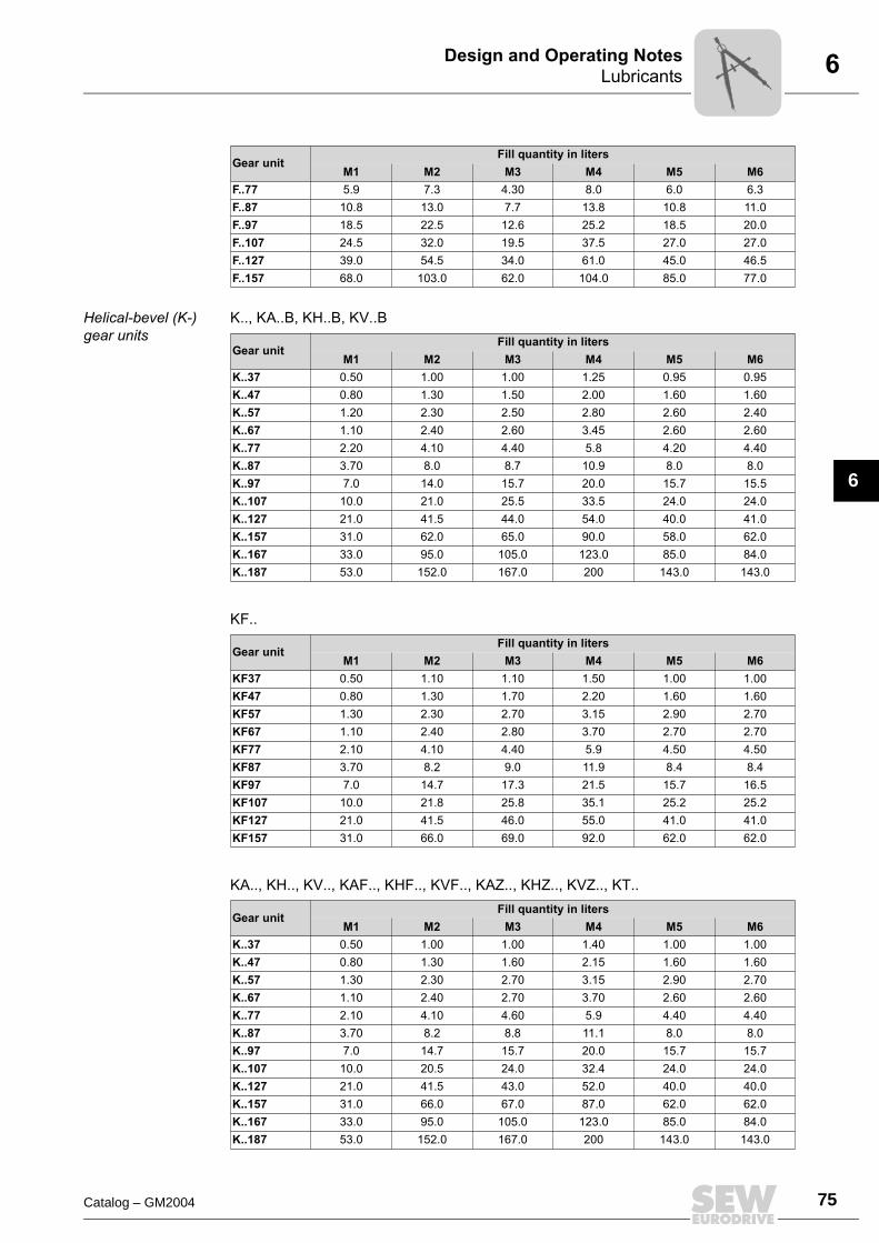
Helical-bevel (K-) gear units
K.., KA..B, KH..B, KV..B
KF..
KA.., KH.., KV.., KAF.., KHF.., KVF.., KAZ.., KHZ.., KVZ.., KT..
F..77 5.9 7.3 4.30 8.0 6.0 6.3F..87 10.8 13.0 7.7 13.8 10.8 11.0F..97 18.5 22.5 12.6 25.2 18.5 20.0F..107 24.5 32.0 19.5 37.5 27.0 27.0F..127 39.0 54.5 34.0 61.0 45.0 46.5F..157 68.0 103.0 62.0 104.0 85.0 77.0
Gear unitFill quantity in liters
M1 M2 M3 M4 M5 M6
Gear unitFill quantity in liters
M1 M2 M3 M4 M5 M6K..37 0.50 1.00 1.00 1.25 0.95 0.95K..47 0.80 1.30 1.50 2.00 1.60 1.60K..57 1.20 2.30 2.50 2.80 2.60 2.40K..67 1.10 2.40 2.60 3.45 2.60 2.60K..77 2.20 4.10 4.40 5.8 4.20 4.40K..87 3.70 8.0 8.7 10.9 8.0 8.0K..97 7.0 14.0 15.7 20.0 15.7 15.5K..107 10.0 21.0 25.5 33.5 24.0 24.0K..127 21.0 41.5 44.0 54.0 40.0 41.0K..157 31.0 62.0 65.0 90.0 58.0 62.0K..167 33.0 95.0 105.0 123.0 85.0 84.0K..187 53.0 152.0 167.0 200 143.0 143.0
Gear unitFill quantity in liters
M1 M2 M3 M4 M5 M6KF37 0.50 1.10 1.10 1.50 1.00 1.00KF47 0.80 1.30 1.70 2.20 1.60 1.60KF57 1.30 2.30 2.70 3.15 2.90 2.70KF67 1.10 2.40 2.80 3.70 2.70 2.70KF77 2.10 4.10 4.40 5.9 4.50 4.50KF87 3.70 8.2 9.0 11.9 8.4 8.4KF97 7.0 14.7 17.3 21.5 15.7 16.5KF107 10.0 21.8 25.8 35.1 25.2 25.2KF127 21.0 41.5 46.0 55.0 41.0 41.0KF157 31.0 66.0 69.0 92.0 62.0 62.0
Gear unitFill quantity in liters
M1 M2 M3 M4 M5 M6K..37 0.50 1.00 1.00 1.40 1.00 1.00K..47 0.80 1.30 1.60 2.15 1.60 1.60K..57 1.30 2.30 2.70 3.15 2.90 2.70K..67 1.10 2.40 2.70 3.70 2.60 2.60K..77 2.10 4.10 4.60 5.9 4.40 4.40K..87 3.70 8.2 8.8 11.1 8.0 8.0K..97 7.0 14.7 15.7 20.0 15.7 15.7K..107 10.0 20.5 24.0 32.4 24.0 24.0K..127 21.0 41.5 43.0 52.0 40.0 40.0K..157 31.0 66.0 67.0 87.0 62.0 62.0K..167 33.0 95.0 105.0 123.0 85.0 84.0K..187 53.0 152.0 167.0 200 143.0 143.0
6
76 Catalog – GM2004
LubricantsDesign and Operating Notes
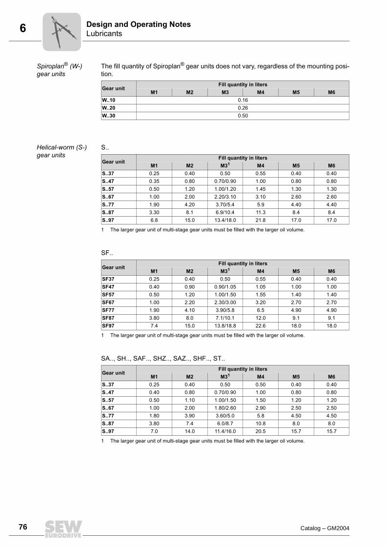
Spiroplan® (W-) gear units
The fill quantity of Spiroplan® gear units does not vary, regardless of the mounting posi-tion.
Helical-worm (S-) gear units
S..
SF..
SA.., SH.., SAF.., SHZ.., SAZ.., SHF.., ST..
Gear unitFill quantity in liters
M1 M2 M3 M4 M5 M6W..10 0.16W..20 0.26W..30 0.50
Gear unitFill quantity in liters
M1 M2 M31
1 The larger gear unit of multi-stage gear units must be filled with the larger oil volume.
M4 M5 M6S..37 0.25 0.40 0.50 0.55 0.40 0.40S..47 0.35 0.80 0.70/0.90 1.00 0.80 0.80S..57 0.50 1.20 1.00/1.20 1.45 1.30 1.30S..67 1.00 2.00 2.20/3.10 3.10 2.60 2.60S..77 1.90 4.20 3.70/5.4 5.9 4.40 4.40S..87 3.30 8.1 6.9/10.4 11.3 8.4 8.4S..97 6.8 15.0 13.4/18.0 21.8 17.0 17.0
Gear unitFill quantity in liters
M1 M2 M31
1 The larger gear unit of multi-stage gear units must be filled with the larger oil volume.
M4 M5 M6SF37 0.25 0.40 0.50 0.55 0.40 0.40SF47 0.40 0.90 0.90/1.05 1.05 1.00 1.00SF57 0.50 1.20 1.00/1.50 1.55 1.40 1.40SF67 1.00 2.20 2.30/3.00 3.20 2.70 2.70SF77 1.90 4.10 3.90/5.8 6.5 4.90 4.90SF87 3.80 8.0 7.1/10.1 12.0 9.1 9.1SF97 7.4 15.0 13.8/18.8 22.6 18.0 18.0
Gear unitFill quantity in liters
M1 M2 M31
1 The larger gear unit of multi-stage gear units must be filled with the larger oil volume.
M4 M5 M6S..37 0.25 0.40 0.50 0.50 0.40 0.40S..47 0.40 0.80 0.70/0.90 1.00 0.80 0.80S..57 0.50 1.10 1.00/1.50 1.50 1.20 1.20S..67 1.00 2.00 1.80/2.60 2.90 2.50 2.50S..77 1.80 3.90 3.60/5.0 5.8 4.50 4.50S..87 3.80 7.4 6.0/8.7 10.8 8.0 8.0S..97 7.0 14.0 11.4/16.0 20.5 15.7 15.7
Catalog – GM2004 77
6
1
2
3
4
7
8
9
10
11
12
13
14
15
16
17
18
19
20
21
22
Installation/removal of gear units with hollow shafts and keysDesign and Operating Notes
6
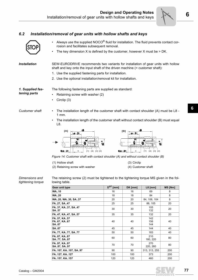
6.2 Installation/removal of gear units with hollow shafts and keys
Installation SEW-EURODRIVE recommends two variants for installation of gear units with hollowshaft and key onto the input shaft of the driven machine (= customer shaft):1. Use the supplied fastening parts for installation.2. Use the optional installation/removal kit for installation.
1. Supplied fas-tening parts
The following fastening parts are supplied as standard:� Retaining screw with washer (2)� Circlip (3)
Customer shaft � The installation length of the customer shaft with contact shoulder (A) must be L8 -1 mm.
� The installation length of the customer shaft without contact shoulder (B) must equalL8.
Dimensions and tightening torque
The retaining screw (2) must be tightened to the tightening torque MS given in the fol-lowing table.
� Always use the supplied NOCO® fluid for installation. The fluid prevents contact cor-rosion and facilitates subsequent removal.
� The key dimension X is defined by the customer, however X must be > DK.
Figure 14: Customer shaft with contact shoulder (A) and without contact shoulder (B)
(1) Hollow shaft (3) Circlip(2) Retaining screw with washer (4) Customer shaft
[1] [2][3][4] [1] [4] [3] [2]
[A] [B]
Gear unit type DH7 [mm] DK [mm] L8 [mm] MS [Nm]WA..10 16 16 69 8WA..20 18 18 84 8WA..20, WA..30, SA..37 20 20 84, 106, 104 8FA..27, SA..47 25 25 88, 105 20FA..37, KA..37, SA..47SA..57 30 30 105
132 20
FA..47, KA..47, SA..57 35 35 132 20FA..57, KA..57FA..67, KA..67SA..67
40 40142156144
40
SA..67 45 45 144 40FA..77, KA..77, SA..77 50 50 183 40FA..87, KA..87SA..77, SA..87 60 60 210
180, 220 80
FA..97, KA..97SA..87, SA..97 70 70 270
220, 260 80
FA..107, KA..107, SA..97 90 90 313, 313, 255 200FA..127, KA..127 100 100 373 200FA..157, KA..157 120 120 460 200
6
78 Catalog – GM2004
Installation/removal of gear units with hollow shafts and keysDesign and Operating Notes
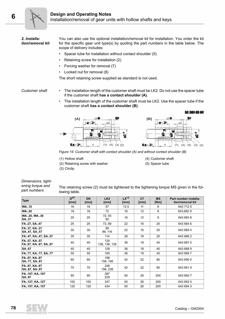
2. Installa-tion/removal kit
You can also use the optional installation/removal kit for installation. You order the kitfor the specific gear unit type(s) by quoting the part numbers in the table below. Thescope of delivery includes:� Spacer tube for installation without contact shoulder (5)� Retaining screw for installation (2)� Forcing washer for removal (7)� Locked nut for removal (8)The short retaining screw supplied as standard is not used.
Customer shaft � The installation length of the customer shaft must be LK2. Do not use the spacer tubeif the customer shaft has a contact shoulder (A).
� The installation length of the customer shaft must be LK2. Use the spacer tube if thecustomer shaft has a contact shoulder (B).
Dimensions, tight-ening torque and part numbers
The retaining screw (2) must be tightened to the tightening torque MS given in the fol-lowing table.
Figure 15: Customer shaft with contact shoulder (A) and without contact shoulder (B)
(1) Hollow shaft (4) Customer shaft(2) Retaining screw with washer (5) Spacer tube(3) Circlip
[1] [2][3][4] [1] [4] [3] [2][5]
[A] [B]
Type DH7
[mm]DK
[mm]LK2[mm]
LX+2
[mm]C7
[mm]MS
[Nm]Part number installa-
tion/removal kitWA..10 16 16 57 12.5 11 8 643 712 5WA..20 18 18 72 16 12 8 643,682 XWA..20, WA..30SA..37 20 20 72, 93
92 16 12 8 643 683 8
FA..27, SA..47 25 25 72, 89 22 16 20 643 684 6FA..37, KA..37SA..47, SA..57 30 30 89
89, 116 22 16 20 643 685 4
FA..47, KA..47, SA..57 35 35 114 28 18 20 643 686 2FA..57, KA..57FA..67, KA..67, SA..67 40 40 124
138, 138, 126 36 18 40 643 687 0
SA..67 45 45 126 36 18 40 643 688 9FA..77, KA..77, SA..77 50 50 165 36 18 40 643 689 7FA..87, KA..87SA..77, SA..87 60 60 188
158, 198 42 22 80 643 690 0
FA..97, KA..97SA..87, SA..97 70 70 248
198, 238 42 22 80 643 691 9
FA..107, KA..107SA..97 90 90 287
229 50 26 200 643 692 7
FA..127, KA..127 100 100 347 50 26 200 643 693 5FA..157, KA..157 120 120 434 50 26 200 643 694 3
Catalog – GM2004 79
6
1
2
3
4
7
8
9
10
11
12
13
14
15
16
17
18
19
20
21
22
Installation/removal of gear units with hollow shafts and keysDesign and Operating Notes
6
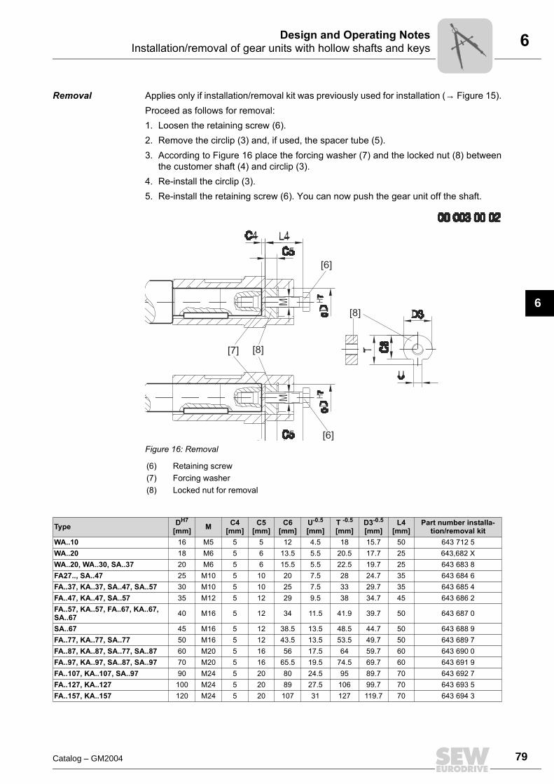
Removal Applies only if installation/removal kit was previously used for installation (→ Figure 15).Proceed as follows for removal:1. Loosen the retaining screw (6).2. Remove the circlip (3) and, if used, the spacer tube (5).3. According to Figure 16 place the forcing washer (7) and the locked nut (8) between
the customer shaft (4) and circlip (3).4. Re-install the circlip (3).5. Re-install the retaining screw (6). You can now push the gear unit off the shaft.
Figure 16: Removal
(6) Retaining screw(7) Forcing washer(8) Locked nut for removal
[6]
[6]
[7] [8]
[8]
Type DH7
[mm] M C4[mm]
C5[mm]
C6[mm]
U-0.5
[mm]T -0.5
[mm]D3-0.5
[mm]L4
[mm]Part number installa-
tion/removal kitWA..10 16 M5 5 5 12 4.5 18 15.7 50 643 712 5WA..20 18 M6 5 6 13.5 5.5 20.5 17.7 25 643,682 XWA..20, WA..30, SA..37 20 M6 5 6 15.5 5.5 22.5 19.7 25 643 683 8FA27.., SA..47 25 M10 5 10 20 7.5 28 24.7 35 643 684 6FA..37, KA..37, SA..47, SA..57 30 M10 5 10 25 7.5 33 29.7 35 643 685 4FA..47, KA..47, SA..57 35 M12 5 12 29 9.5 38 34.7 45 643 686 2FA..57, KA..57, FA..67, KA..67, SA..67 40 M16 5 12 34 11.5 41.9 39.7 50 643 687 0
SA..67 45 M16 5 12 38.5 13.5 48.5 44.7 50 643 688 9FA..77, KA..77, SA..77 50 M16 5 12 43.5 13.5 53.5 49.7 50 643 689 7FA..87, KA..87, SA..77, SA..87 60 M20 5 16 56 17.5 64 59.7 60 643 690 0FA..97, KA..97, SA..87, SA..97 70 M20 5 16 65.5 19.5 74.5 69.7 60 643 691 9FA..107, KA..107, SA..97 90 M24 5 20 80 24.5 95 89.7 70 643 692 7FA..127, KA..127 100 M24 5 20 89 27.5 106 99.7 70 643 693 5FA..157, KA..157 120 M24 5 20 107 31 127 119.7 70 643 694 3
6
80 Catalog – GM2004
Gear units with hollow shaftDesign and Operating Notes
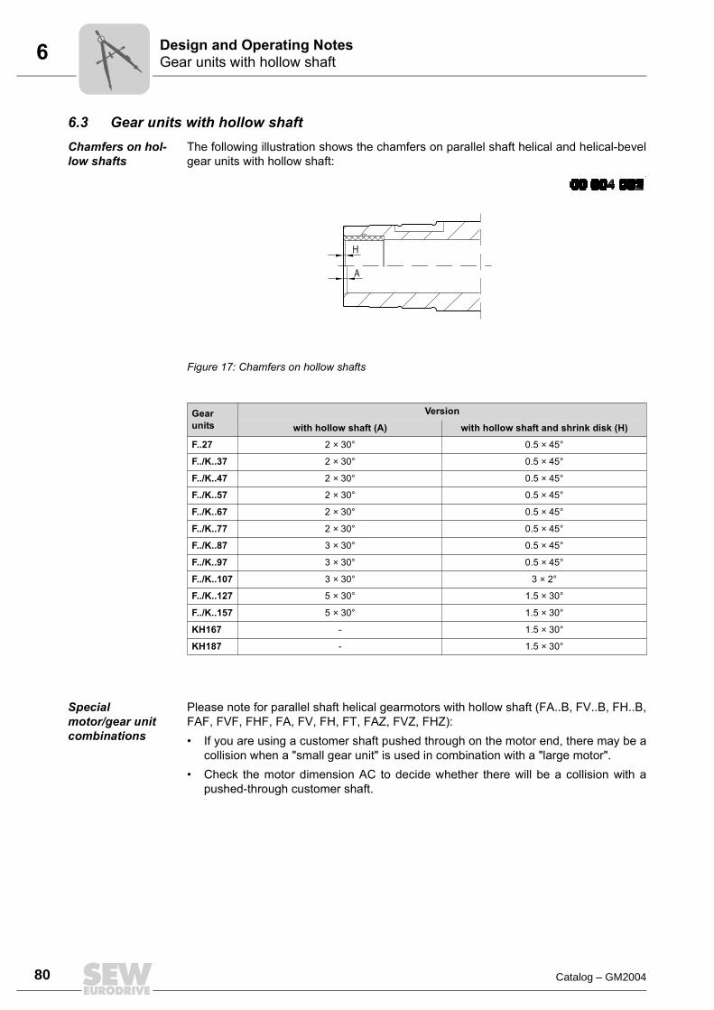
6.3 Gear units with hollow shaftChamfers on hol-low shafts
The following illustration shows the chamfers on parallel shaft helical and helical-bevelgear units with hollow shaft:
Special motor/gear unit combinations
Please note for parallel shaft helical gearmotors with hollow shaft (FA..B, FV..B, FH..B,FAF, FVF, FHF, FA, FV, FH, FT, FAZ, FVZ, FHZ):� If you are using a customer shaft pushed through on the motor end, there may be a
collision when a "small gear unit" is used in combination with a "large motor".� Check the motor dimension AC to decide whether there will be a collision with a
pushed-through customer shaft.
Figure 17: Chamfers on hollow shafts
Gear units
Versionwith hollow shaft (A) with hollow shaft and shrink disk (H)
F..27 2 × 30° 0.5 × 45°
F../K..37 2 × 30° 0.5 × 45°
F../K..47 2 × 30° 0.5 × 45°
F../K..57 2 × 30° 0.5 × 45°
F../K..67 2 × 30° 0.5 × 45°
F../K..77 2 × 30° 0.5 × 45°
F../K..87 3 × 30° 0.5 × 45°
F../K..97 3 × 30° 0.5 × 45°
F../K..107 3 × 30° 3 × 2°
F../K..127 5 × 30° 1.5 × 30°
F../K..157 5 × 30° 1.5 × 30°
KH167 - 1.5 × 30°
KH187 - 1.5 × 30°
Catalog – GM2004 81
6
1
2
3
4
7
8
9
10
11
12
13
14
15
16
17
18
19
20
21
22
TorqLOC® mounting system for gear units with hollow shaftDesign and Operating Notes
6
6.4 TorqLOC® mounting system for gear units with hollow shaftDescription of TorqLOC®
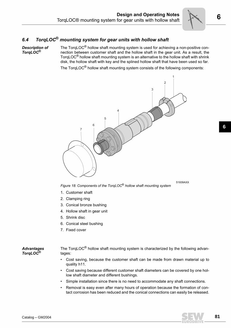
The TorqLOC® hollow shaft mounting system is used for achieving a non-positive con-nection between customer shaft and the hollow shaft in the gear unit. As a result, theTorqLOC® hollow shaft mounting system is an alternative to the hollow shaft with shrinkdisk, the hollow shaft with key and the splined hollow shaft that have been used so far.The TorqLOC® hollow shaft mounting system consists of the following components:
1. Customer shaft2. Clamping ring3. Conical bronze bushing4. Hollow shaft in gear unit5. Shrink disc6. Conical steel bushing7. Fixed cover
Advantages TorqLOC®
The TorqLOC® hollow shaft mounting system is characterized by the following advan-tages:� Cost saving, because the customer shaft can be made from drawn material up to
quality h11.� Cost saving because different customer shaft diameters can be covered by one hol-
low shaft diameter and different bushings.� Simple installation since there is no need to accommodate any shaft connections.� Removal is easy even after many hours of operation because the formation of con-
tact corrosion has been reduced and the conical connections can easily be released.
51939AXXFigure 18: Components of the TorqLOC® hollow shaft mounting system
6
5
4
3
2
1
7
6
82 Catalog – GM2004
TorqLOC® mounting system for gear units with hollow shaftDesign and Operating Notes
Technical Data The TorqLOC® hollow shaft mounting system is approved for input torques of 92 Nm to4300 Nm.The following gear units are available with TorqLOC® hollow shaft mounting system:� Parallel shaft helical gear units in gear unit sizes 37 to 97 (FT37 ... FT97)� Helical-bevel gear units in gear unit sizes 37 to 97 (KT37 ... KT97)� Helical-worm gear units in gear unit sizes 37 to 97 (ST37 ... ST97)
Available options The following options are available for gear units with a TorqLOC® hollow shaft mount-ing system:� Helical-bevel and helical-worm gear units with TorqLOC® (KT.., ST..): The "torque
arm" (../T) option is available.� Parallel shaft helical gear units with TorqLOC® (FT..): The "rubber buffer" (../G) op-
tion is available.
Catalog – GM2004 83
6
1
2
3
4
7
8
9
10
11
12
13
14
15
16
17
18
19
20
21
22
Option, offset hollow shaft with shrink diskDesign and Operating Notes
6
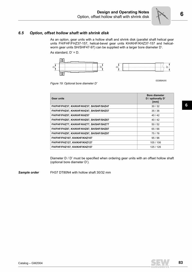
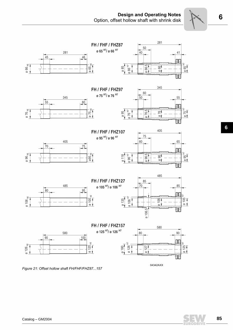
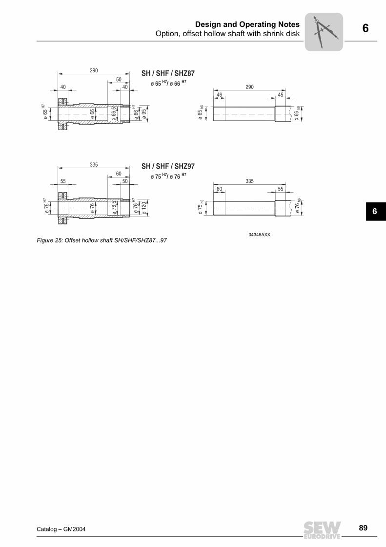
6.5 Option, offset hollow shaft with shrink diskAs an option, gear units with a hollow shaft and shrink disk (parallel shaft helical gearunits FH/FHF/FHZ37-157, helical-bevel gear units KH/KHF/KHZ37-157 and helical-worm gear units SH/SHF47-97) can be supplied with a larger bore diameter D�.As standard, D� = D.
Diameter D / D� must be specified when ordering gear units with an offset hollow shaft(optional bore diameter D�).
Sample order FH37 DT80N4 with hollow shaft 30/32 mm
03389AXXFigure 19: Optional bore diameter D�
Gear unitsBore diameter
D / optionally D�[mm]
FH/FHF/FHZ37, KH/KHF/KHZ37, SH/SHF/SHZ47 30 / 32
FH/FHF/FHZ47, KH/KHF/KHZ47, SH/SHF/SHZ57 35 / 36
FH/FHF/FHZ57, KH/KHF/KHZ57 40 / 42
FH/FHF/FHZ67, KH/KHF/KHZ67, SH/SHF/SHZ67 40 / 42
FH/FHF/FHZ77, KH/KHF/KHZ77, SH/SHF/SHZ77 50 / 52
FH/FHF/FHZ87, KH/KHF/KHZ87, SH/SHF/SHZ87 65 / 66
FH/FHF/FHZ97, KH/KHF/KHZ97, SH/SHF/SHZ97 75 / 76
FH/FHF/FHZ107, KH/KHF/KHZ107 95 / 96
FH/FHF/FHZ127, KH/KHF/KHZ127 105 / 106
FH/FHF/FHZ157, KH/KHF/KHZ157 125 / 126
D D'
D D'
6
84 Catalog – GM2004
Option, offset hollow shaft with shrink diskDesign and Operating Notes
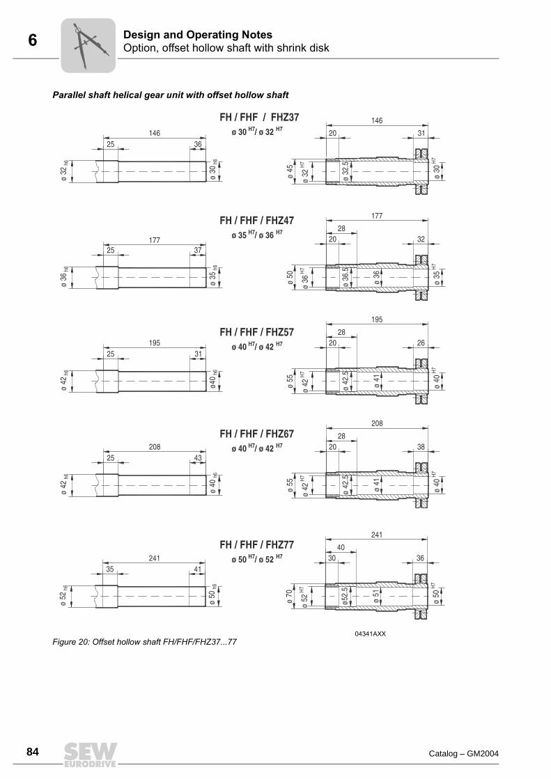
Parallel shaft helical gear unit with offset hollow shaft
04341AXXFigure 20: Offset hollow shaft FH/FHF/FHZ37...77
Catalog – GM2004 85
6
1
2
3
4
7
8
9
10
11
12
13
14
15
16
17
18
19
20
21
22
Option, offset hollow shaft with shrink diskDesign and Operating Notes
6
04342AXXFigure 21: Offset hollow shaft FH/FHF/FHZ87...157
6
86 Catalog – GM2004
Option, offset hollow shaft with shrink diskDesign and Operating Notes
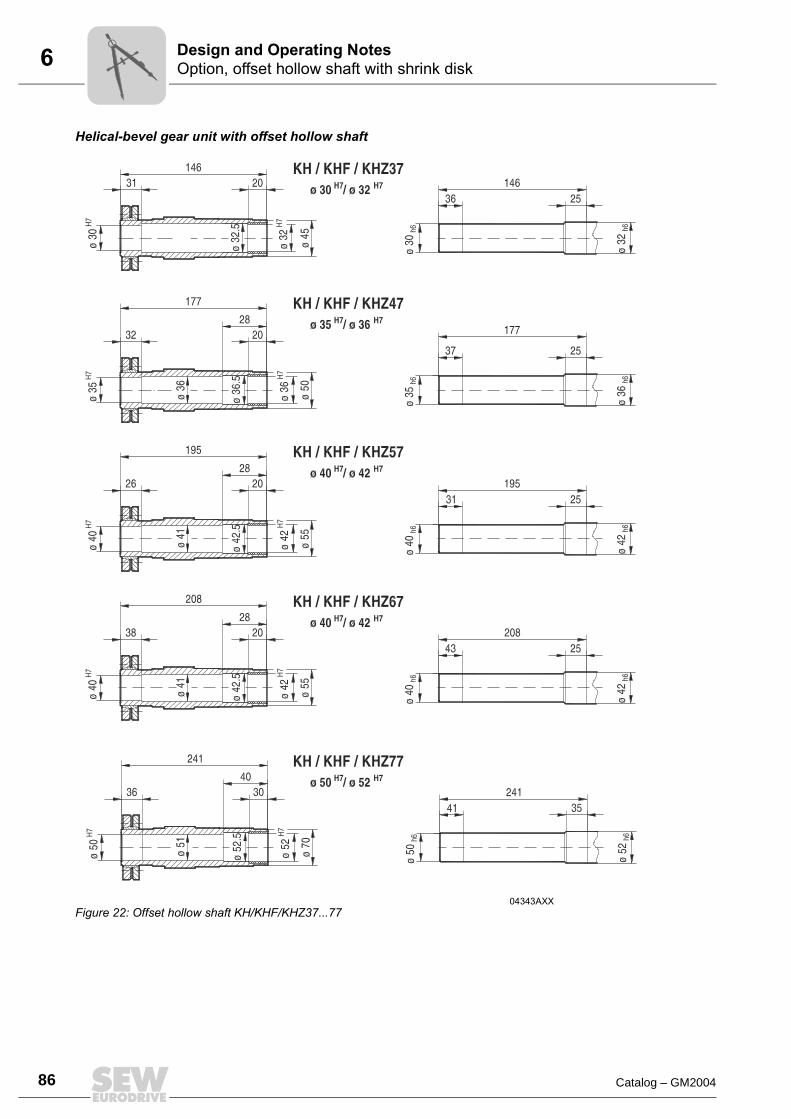
Helical-bevel gear unit with offset hollow shaft
04343AXXFigure 22: Offset hollow shaft KH/KHF/KHZ37...77
Catalog – GM2004 87
6
1
2
3
4
7
8
9
10
11
12
13
14
15
16
17
18
19
20
21
22
Option, offset hollow shaft with shrink diskDesign and Operating Notes
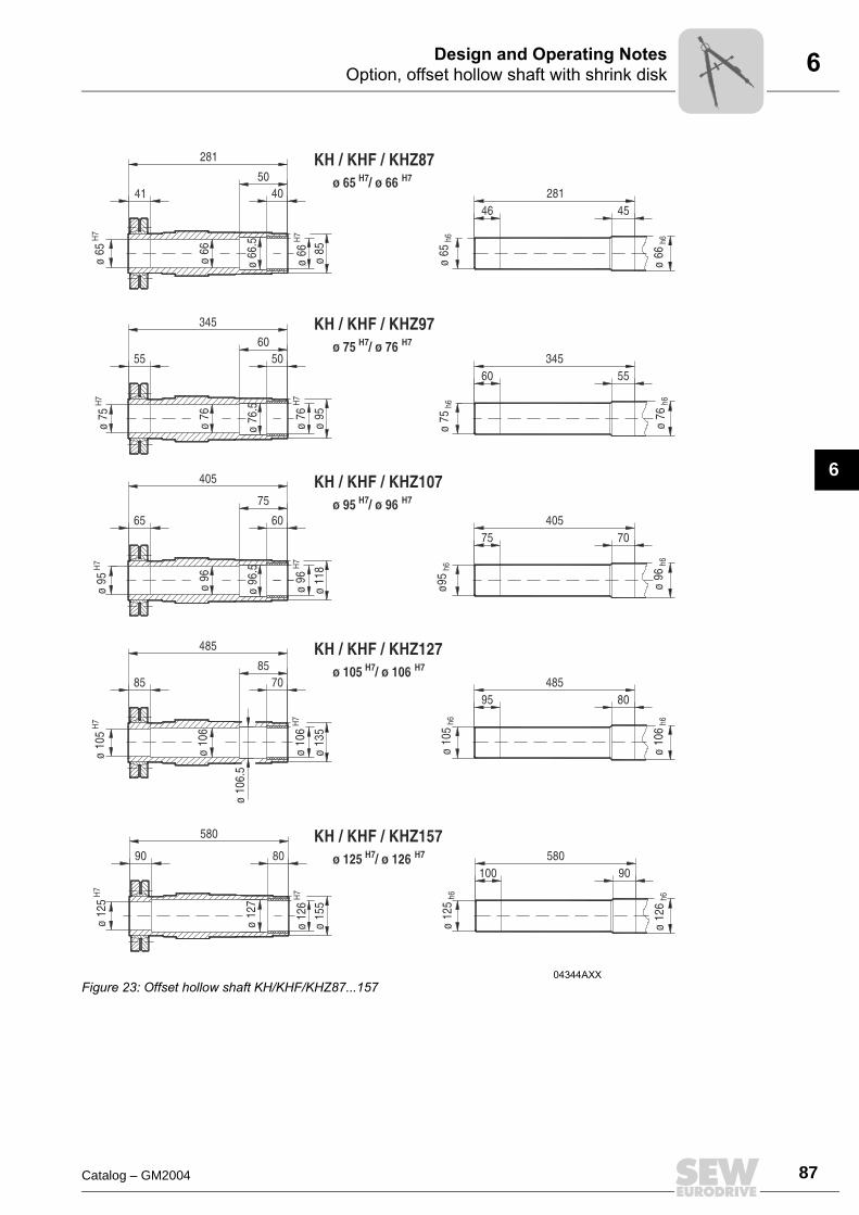
6
04344AXXFigure 23: Offset hollow shaft KH/KHF/KHZ87...157
6
88 Catalog – GM2004
Option, offset hollow shaft with shrink diskDesign and Operating Notes
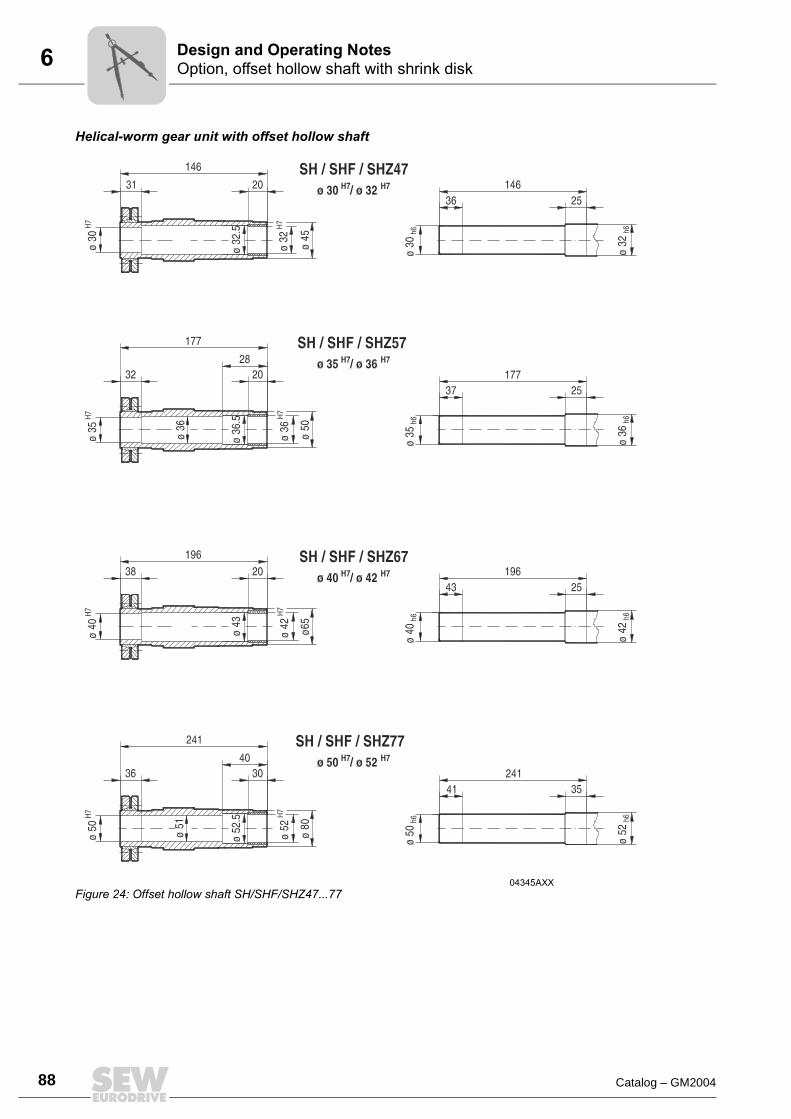
Helical-worm gear unit with offset hollow shaft
04345AXXFigure 24: Offset hollow shaft SH/SHF/SHZ47...77
Catalog – GM2004 89
6
1
2
3
4
7
8
9
10
11
12
13
14
15
16
17
18
19
20
21
22
Option, offset hollow shaft with shrink diskDesign and Operating Notes
6
04346AXXFigure 25: Offset hollow shaft SH/SHF/SHZ87...97
6
90 Catalog – GM2004
Adapter for installation of IEC motorsDesign and Operating Notes
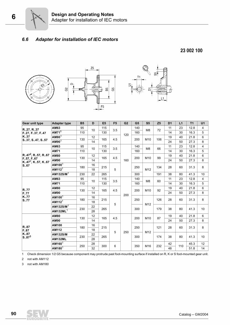
6.6 Adapter for installation of IEC motors
Gear unit type Adapter type B5 D E5 F5 G2 G5 S5 Z5 D1 L1 T1 U1
R..27, R..37F..27, F..37, F..47K..37S..37, S..47, S..57
AM63 9510
1153.5
120
140M8 72
11 23 12.8 4AM711 110 130 160 14 30 16.3 5AM801
13012
165 4.5 200 M10 10619 40 21.8 6
AM901 14 24 50 27.3 8
R..472, R..57, R..67F..57, F..67K..472, K..57, K..67S..67
AM63 9510
1153.5
160
140M8 66
11 23 12.8 4AM71 110 130 160 14 30 16.3 5AM80
13012
165 4.5 200 M10 9919 40 21.8 6
AM90 14 24 50 27.3 8AM1001
18016
2155
250M12
134 28 60 31.3 8AM1121 18AM132S/M1 230 22 265 300 191 38 80 41.3 10
R..77F..77K..77S..77
AM63 9510
1153.5
200
140M8 60
11 23 12.8 4AM71 110 130 160 14 30 16.3 5AM80
13012
165 4.5 200 M10 9219 40 21.8 6
AM90 14 24 50 27.3 8AM1001
18016
2155
250M12
126 28 60 31.3 8AM1121 18AM132S/M1
23022
265 300 179 38 80 41.3 10AM132ML1 28
R..87F..87K..87S..873
AM80130
12165 4.5
250
200 M10 8719 40 21.8 6
AM90 14 24 50 27.3 8AM100
18016
2155
250M12
121 28 60 31.3 8AM112 18AM132S/M
23022
265 300 174 38 80 41.3 10AM132ML 28AM1601
25028
300 6 350 M16 23242
11045.3 12
AM1801 32 48 51.8 14
1 Check dimension 1/2 G5 because component may protrude past foot-mounting surface if installed on R, K or S foot-mounted gear unit.2 not with AM1123 not with AM180
Catalog – GM2004 91
6
1
2
3
4
7
8
9
10
11
12
13
14
15
16
17
18
19
20
21
22
Adapter for installation of IEC motorsDesign and Operating Notes
6
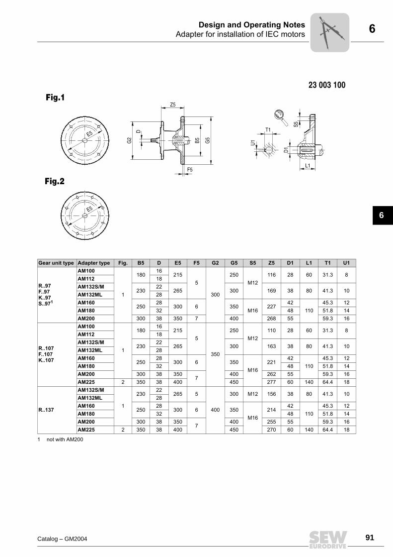
Gear unit type Adapter type Fig. B5 D E5 F5 G2 G5 S5 Z5 D1 L1 T1 U1
R..97F..97K..97S..971
AM100
1
18016
2155
300
250M12
116 28 60 31.3 8AM112 18AM132S/M
23022
265 300 169 38 80 41.3 10AM132ML 28AM160
25028
300 6 350M16
22742
11045.3 12
AM180 32 48 51.8 14AM200 300 38 350 7 400 268 55 59.3 16
R..107F..107K..107
AM100
1
18016
2155
350
250M12
110 28 60 31.3 8AM112 18AM132S/M
23022
265 300 163 38 80 41.3 10AM132ML 28AM160
25028
300 6 350M16
22142
11045.3 12
AM180 32 48 51.8 14AM200 300 38 350
7400 262 55 59.3 16
AM225 2 350 38 400 450 277 60 140 64.4 18
R..137
AM132S/M
1
23022
265 5
400
300 M12 156 38 80 41.3 10AM132ML 28AM160
25028
300 6 350M16
21442
11045.3 12
AM180 32 48 51.8 14AM200 300 38 350
7400 255 55 59.3 16
AM225 2 350 38 400 450 270 60 140 64.4 18
1 not with AM200
6
92 Catalog – GM2004
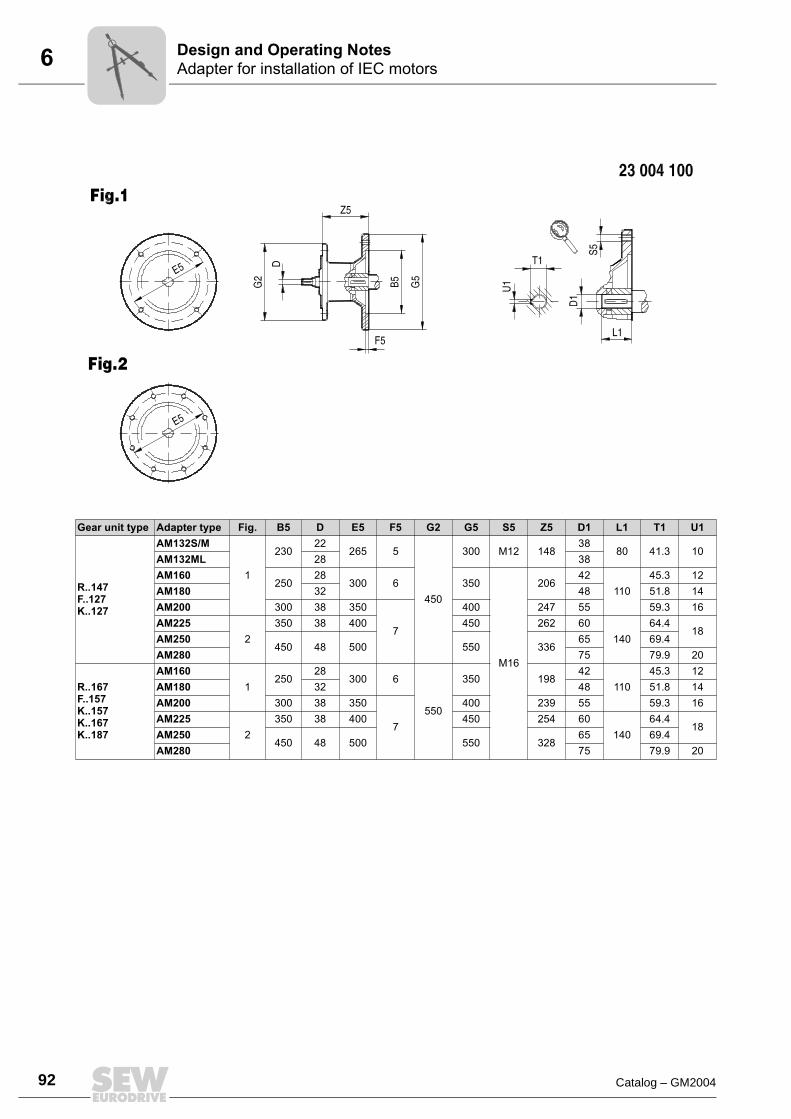
Adapter for installation of IEC motorsDesign and Operating Notes
Gear unit type Adapter type Fig. B5 D E5 F5 G2 G5 S5 Z5 D1 L1 T1 U1
R..147F..127K..127
AM132S/M
1
23022
265 5
450
300 M12 14838
80 41.3 10AM132ML 28 38AM160
25028
300 6 350
M16
20642
11045.3 12
AM180 32 48 51.8 14AM200 300 38 350
7
400 247 55 59.3 16AM225
2350 38 400 450 262 60
14064.4
18AM250
450 48 500 550 33665 69.4
AM280 75 79.9 20
R..167F..157K..157K..167K..187
AM1601
25028
300 6
550
350 19842
11045.3 12
AM180 32 48 51.8 14AM200 300 38 350
7
400 239 55 59.3 16AM225
2350 38 400 450 254 60
14064.4
18AM250
450 48 500 550 32865 69.4
AM280 75 79.9 20
Catalog – GM2004 93
6
1
2
3
4
7
8
9
10
11
12
13
14
15
16
17
18
19
20
21
22
Adapter for installation of servomotorsDesign and Operating Notes
6
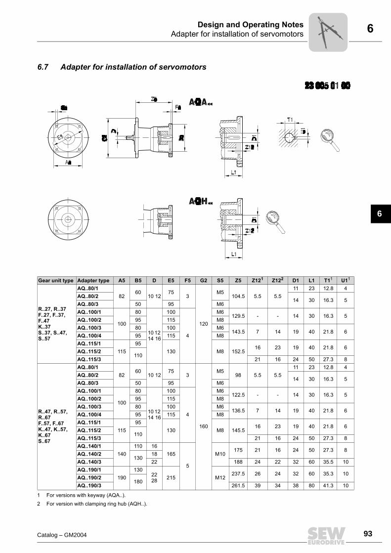
6.7 Adapter for installation of servomotors
Gear unit type Adapter type A5 B5 D E5 F5 G2 S5 Z5 Z121 Z122 D1 L1 T11 U11
R..27, R..37F..27, F..37, F..47K..37S..37, S..47,S..57
AQ..80/182
6010 12
753
120
M5104.5 5.5 5.5
11 23 12.8 4AQ..80/2
14 30 16.3 5AQ..80/3 50 95 M6AQ..100/1
100
80
10 12 14 16
100
4
M6129.5 - - 14 30 16.3 5
AQ..100/2 95 115 M8AQ..100/3 80 100 M6
143.5 7 14 19 40 21.8 6AQ..100/4 95 115 M8AQ..115/1
11595
130 M8 152.516 23 19 40 21.8 6
AQ..115/2110
AQ..115/3 21 16 24 50 27.3 8
R..47, R..57,R..67F..57, F..67K..47, K..57,K..67S..67
AQ..80/182
6010 12
753
160
M598 5.5 5.5
11 23 12.8 4AQ..80/2
14 30 16.3 5AQ..80/3 50 95 M6AQ..100/1
100
80
10 12 14 16
100
4
M6122.5 - - 14 30 16.3 5
AQ..100/2 95 115 M8AQ..100/3 80 100 M6
136.5 7 14 19 40 21.8 6AQ..100/4 95 115 M8AQ..115/1
11595
130 M8 145.516 23 19 40 21.8 6
AQ..115/2110
AQ..115/3 21 16 24 50 27.3 8AQ..140/1
140110 16
165
5
M10175 21 16 24 50 27.3 8
AQ..140/2130
18AQ..140/3 22 188 24 22 32 60 35.5 10AQ..190/1
190130
2228 215 M12
237.5 26 24 32 60 35.3 10AQ..190/2
180AQ..190/3 261.5 39 34 38 80 41.3 10
1 For versions with keyway (AQA..).2 For version with clamping ring hub (AQH..).
6
94 Catalog – GM2004
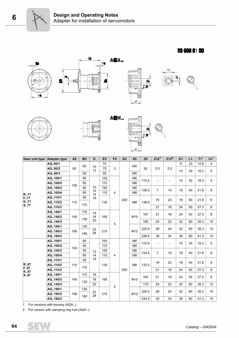
Adapter for installation of servomotorsDesign and Operating Notes
Gear unit type Adapter type A5 B5 D E5 F5 G2 S5 Z5 Z121 Z122 D1 L1 T11 U11
R..77F..77K..77S..77
AQ..80/182
60 1012
753
200
M592 5.5 5.5
11 23 12.8 4AQ..80/2 75
14 30 16.3 5AQ..80/3 50 95 M6AQ..100/1
100
80
10121416
100
4
M6115.5 - - 14 30 16.3 5
AQ..100/2 95 115 M8AQ..100/3 80 100 M6
129.5 7 14 19 40 21.8 6AQ..100/4 95 115 M8AQ..115/1
11595
130 M8 138.516 23 19 40 21.8 6
AQ..115/2110
AQ..115/3 21 16 24 50 27.3 8AQ..140/1
140110 16
1822
165
5
M10167 21 16 24 50 27.3 8
AQ..140/2130
AQ..140/3 180 24 22 32 60 35.3 10AQ..190/1
190130
2228 215 M12
225.5 26 24 32 60 35.3 10AQ..190/2
180AQ..190/3 249.5 39 34 38 80 41.3 10
R..87F..87K..87S..87
AQ..100/1
100
80
121416
100
4
250
M6110.5 - - 14 30 16.3 5
AQ..100/2 95 115 M8AQ..100/3 80 100 M6
124.5 7 14 19 40 21.8 6AQ..100/4 95 115 M8AQ..115/1
11595
130 M8 133.516 23 19 40 21.8 6
AQ..115/2110
AQ..115/3 21 16 24 50 27.3 8AQ..140/1
140110 16
165
5
M10162 21 16 24 50 27.3 8
AQ..140/2130
18AQ..140/3 22 175 24 22 32 60 35.3 10AQ..190/1
190130
2228 215 M12
220.5 26 24 32 60 35.3 10AQ..190/2
180AQ..190/3 244.5 39 34 38 80 41.3 10
1 For versions with keyway (AQA..).2 For version with clamping ring hub (AQH..).
Catalog – GM2004 95
6
1
2
3
4
7
8
9
10
11
12
13
14
15
16
17
18
19
20
21
22
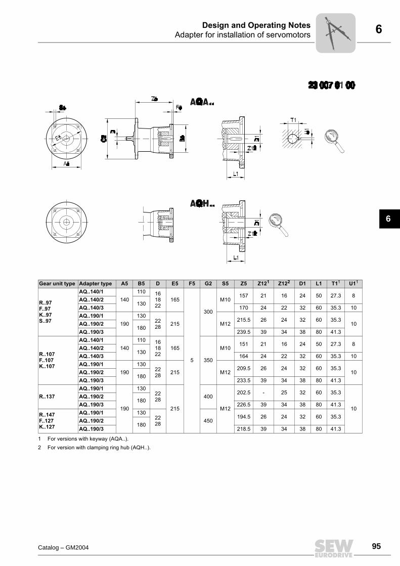
Adapter for installation of servomotorsDesign and Operating Notes
6
Gear unit type Adapter type A5 B5 D E5 F5 G2 S5 Z5 Z121 Z122 D1 L1 T11 U11
R..97F..97K..97S..97
AQ..140/1140
110 161822
165
5
300
M10157 21 16 24 50 27.3 8
AQ..140/2130
AQ..140/3 170 24 22 32 60 35.3 10AQ..190/1
190130
2228 215 M12
215.5 26 24 32 60 35.310AQ..190/2
180AQ..190/3 239.5 39 34 38 80 41.3
R..107F..107K..107
AQ..140/1140
110 161822
165
350
M10151 21 16 24 50 27.3 8
AQ..140/2130
AQ..140/3 164 24 22 32 60 35.3 10AQ..190/1
190130
2228 215 M12
209.5 26 24 32 60 35.310AQ..190/2
180AQ..190/3 233.5 39 34 38 80 41.3
R..137AQ..190/1
190
1302228
215
400
M12
202.5 - 25 32 60 35.3
10
AQ..190/2180
AQ..190/3 226.5 39 34 38 80 41.3
R..147F..127K..127
AQ..190/1 1302228 450
194.5 26 24 32 60 35.3AQ..190/2
180AQ..190/3 218.5 39 34 38 80 41.3
1 For versions with keyway (AQA..).2 For version with clamping ring hub (AQH..).
6
96 Catalog – GM2004
Flange contours of RF.. and R..F gearmotorsDesign and Operating Notes
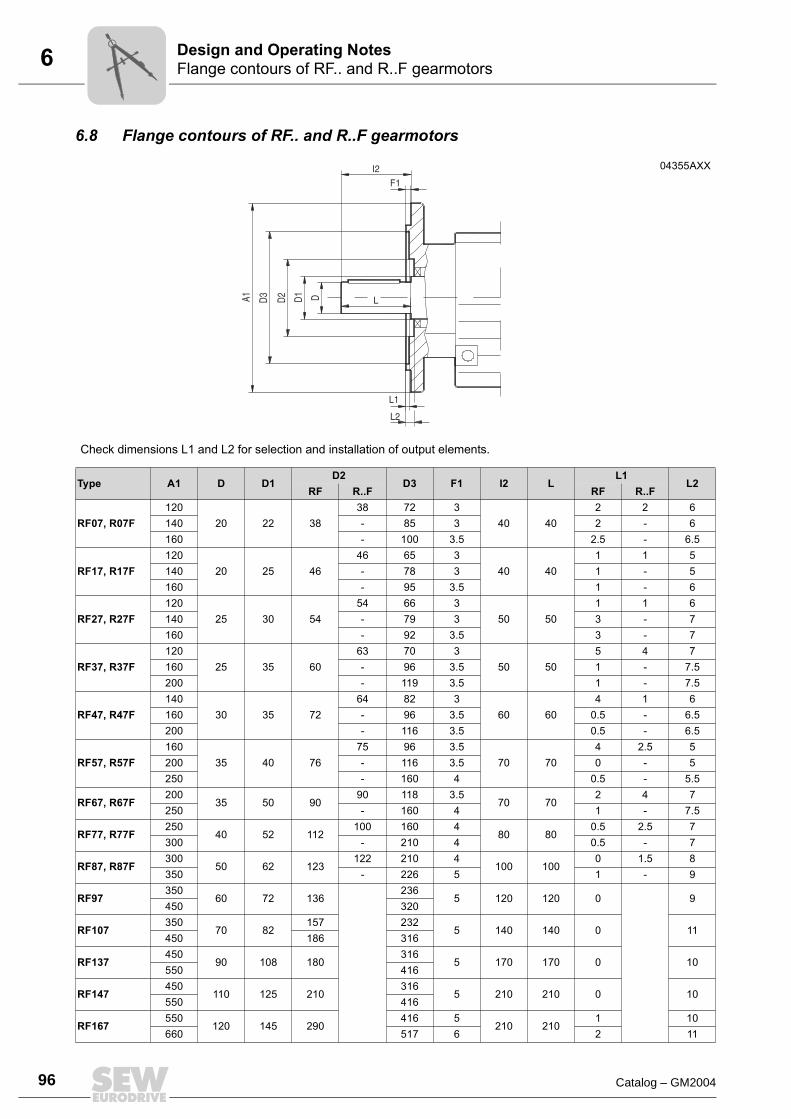
6.8 Flange contours of RF.. and R..F gearmotors
04355AXX
Check dimensions L1 and L2 for selection and installation of output elements.
Type A1 D D1D2
D3 F1 I2 LL1
L2RF R..F RF R..F
RF07, R07F120
20 22 3838 72 3
40 402 2 6
140 - 85 3 2 - 6160 - 100 3.5 2.5 - 6.5
RF17, R17F120
20 25 4646 65 3
40 401 1 5
140 - 78 3 1 - 5160 - 95 3.5 1 - 6
RF27, R27F120
25 30 5454 66 3
50 501 1 6
140 - 79 3 3 - 7160 - 92 3.5 3 - 7
RF37, R37F120
25 35 6063 70 3
50 505 4 7
160 - 96 3.5 1 - 7.5200 - 119 3.5 1 - 7.5
RF47, R47F140
30 35 7264 82 3
60 604 1 6
160 - 96 3.5 0.5 - 6.5200 - 116 3.5 0.5 - 6.5
RF57, R57F160
35 40 7675 96 3.5
70 704 2.5 5
200 - 116 3.5 0 - 5250 - 160 4 0.5 - 5.5
RF67, R67F200
35 50 9090 118 3.5
70 702 4 7
250 - 160 4 1 - 7.5
RF77, R77F250
40 52 112100 160 4
80 800.5 2.5 7
300 - 210 4 0.5 - 7
RF87, R87F300
50 62 123122 210 4
100 1000 1.5 8
350 - 226 5 1 - 9
RF97350
60 72 136236
5 120 120 0 9450 320
RF107350
70 82157 232
5 140 140 0 11450 186 316
RF137450
90 108 180316
5 170 170 0 10550 416
RF147450
110 125 210316
5 210 210 0 10550 416
RF167550
120 145 290416 5
210 2101 10
660 517 6 2 11
Catalog – GM2004 97
6
1
2
3
4
7
8
9
10
11
12
13
14
15
16
17
18
19
20
21
22
Fastening of gear unitsDesign and Operating Notes
6
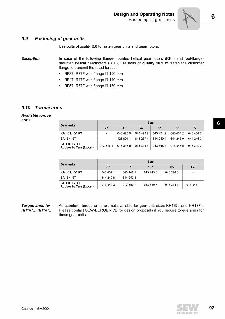
6.9 Fastening of gear unitsUse bolts of quality 8.8 to fasten gear units and gearmotors.
Exception In case of the following flange-mounted helical gearmotors (RF..) and foot/flange-mounted helical gearmotors (R..F), use bolts of quality 10.9 to fasten the customerflange to transmit the rated torque:� RF37, R37F with flange ∅ 120 mm� RF47, R47F with flange ∅ 140 mm� RF57, R57F with flange ∅ 160 mm
6.10 Torque armsAvailable torque arms
Torque arms for KH167.., KH187..
As standard, torque arms are not available for gear unit sizes KH167.. and KH187...Please contact SEW-EURODRIVE for design proposals if you require torque arms forthese gear units.
Gear unitsSize
27 37 47 57 67 77KA, KH, KV, KT - 643 425 8 643 428 2 643 431 2 643 431 2 643 434 7
SA, SH, ST - 126 994 1 644 237 4 644 240 4 644 243 9 644 246 3
FA, FH, FV, FTRubber buffers (2 pcs.) 013 348 5 013 348 5 013 348 5 013 348 5 013 348 5 013 349 3
Gear unitsSize
87 97 107 127 157KA, KH, KV, KT 643 437 1 643 440 1 643 443 6 643 294 8 -
SA, SH, ST 644 249 8 644 252 8 - - -
FA, FH, FV, FTRubber buffers (2 pcs.) 013 349 3 013 350 7 013 350 7 013 351 5 013 347 7
6
98 Catalog – GM2004
Fixed coversDesign and Operating Notes
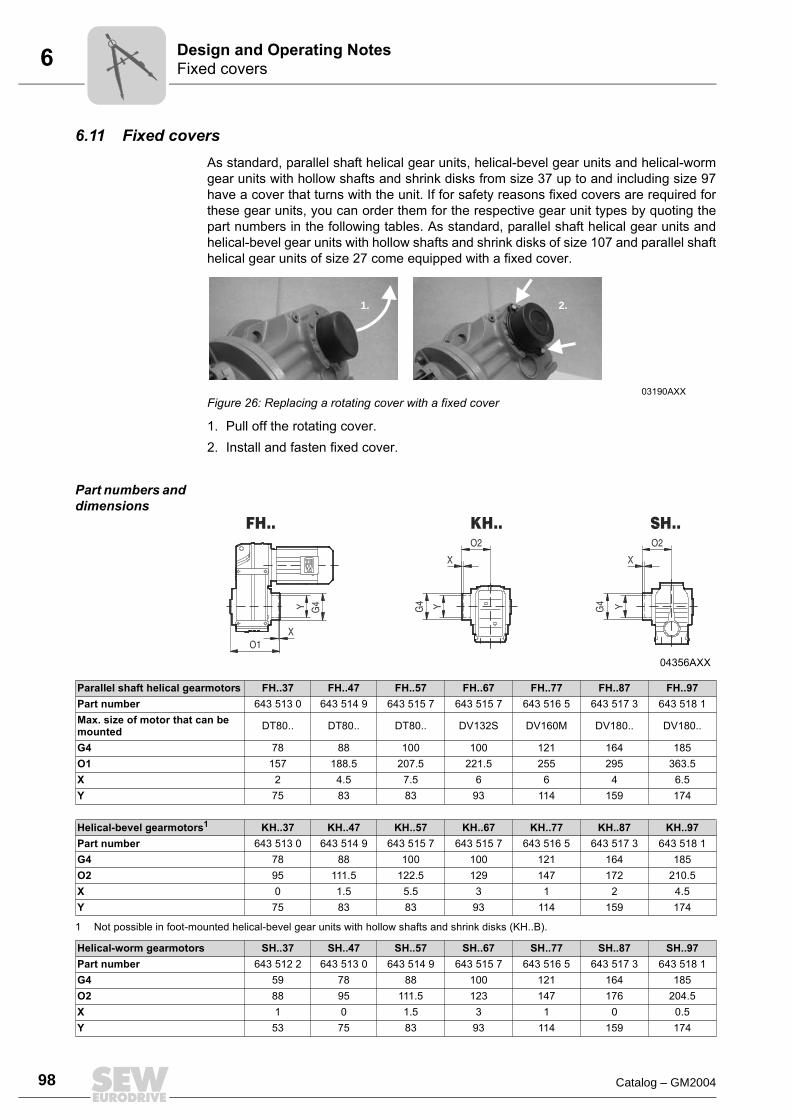
6.11 Fixed coversAs standard, parallel shaft helical gear units, helical-bevel gear units and helical-wormgear units with hollow shafts and shrink disks from size 37 up to and including size 97have a cover that turns with the unit. If for safety reasons fixed covers are required forthese gear units, you can order them for the respective gear unit types by quoting thepart numbers in the following tables. As standard, parallel shaft helical gear units andhelical-bevel gear units with hollow shafts and shrink disks of size 107 and parallel shafthelical gear units of size 27 come equipped with a fixed cover.
1. Pull off the rotating cover.2. Install and fasten fixed cover.
Part numbers and dimensions
03190AXXFigure 26: Replacing a rotating cover with a fixed cover
1. 2.
04356AXX
Parallel shaft helical gearmotors FH..37 FH..47 FH..57 FH..67 FH..77 FH..87 FH..97Part number 643 513 0 643 514 9 643 515 7 643 515 7 643 516 5 643 517 3 643 518 1Max. size of motor that can be mounted DT80.. DT80.. DT80.. DV132S DV160M DV180.. DV180..
G4 78 88 100 100 121 164 185O1 157 188.5 207.5 221.5 255 295 363.5X 2 4.5 7.5 6 6 4 6.5Y 75 83 83 93 114 159 174
Helical-bevel gearmotors1 KH..37 KH..47 KH..57 KH..67 KH..77 KH..87 KH..97Part number 643 513 0 643 514 9 643 515 7 643 515 7 643 516 5 643 517 3 643 518 1G4 78 88 100 100 121 164 185O2 95 111.5 122.5 129 147 172 210.5X 0 1.5 5.5 3 1 2 4.5Y 75 83 83 93 114 159 174
1 Not possible in foot-mounted helical-bevel gear units with hollow shafts and shrink disks (KH..B).
Helical-worm gearmotors SH..37 SH..47 SH..57 SH..67 SH..77 SH..87 SH..97Part number 643 512 2 643 513 0 643 514 9 643 515 7 643 516 5 643 517 3 643 518 1G4 59 78 88 100 121 164 185O2 88 95 111.5 123 147 176 204.5X 1 0 1.5 3 1 0 0.5Y 53 75 83 93 114 159 174